US8100828B2 - Distraction and retraction system for spinal surgery - Google Patents
Distraction and retraction system for spinal surgeryDownload PDFInfo
- Publication number
- US8100828B2 US8100828B2US10/720,656US72065603AUS8100828B2US 8100828 B2US8100828 B2US 8100828B2US 72065603 AUS72065603 AUS 72065603AUS 8100828 B2US8100828 B2US 8100828B2
- Authority
- US
- United States
- Prior art keywords
- retractors
- frame
- retractor
- adjustment
- attachable
- Prior art date
- Legal status (The legal status is an assumption and is not a legal conclusion. Google has not performed a legal analysis and makes no representation as to the accuracy of the status listed.)
- Expired - Lifetime, expires
Links
Images


Classifications
- A—HUMAN NECESSITIES
- A61—MEDICAL OR VETERINARY SCIENCE; HYGIENE
- A61B—DIAGNOSIS; SURGERY; IDENTIFICATION
- A61B17/00—Surgical instruments, devices or methods
- A61B17/02—Surgical instruments, devices or methods for holding wounds open, e.g. retractors; Tractors
- A61B17/0293—Surgical instruments, devices or methods for holding wounds open, e.g. retractors; Tractors with ring member to support retractor elements
- A—HUMAN NECESSITIES
- A61—MEDICAL OR VETERINARY SCIENCE; HYGIENE
- A61B—DIAGNOSIS; SURGERY; IDENTIFICATION
- A61B17/00—Surgical instruments, devices or methods
- A61B17/56—Surgical instruments or methods for treatment of bones or joints; Devices specially adapted therefor
- A61B17/58—Surgical instruments or methods for treatment of bones or joints; Devices specially adapted therefor for osteosynthesis, e.g. bone plates, screws or setting implements
- A61B17/68—Internal fixation devices, including fasteners and spinal fixators, even if a part thereof projects from the skin
- A61B17/70—Spinal positioners or stabilisers, e.g. stabilisers comprising fluid filler in an implant
- A61B17/7074—Tools specially adapted for spinal fixation operations other than for bone removal or filler handling
- A61B17/7076—Tools specially adapted for spinal fixation operations other than for bone removal or filler handling for driving, positioning or assembling spinal clamps or bone anchors specially adapted for spinal fixation
- A61B17/7077—Tools specially adapted for spinal fixation operations other than for bone removal or filler handling for driving, positioning or assembling spinal clamps or bone anchors specially adapted for spinal fixation for moving bone anchors attached to vertebrae, thereby displacing the vertebrae
- A—HUMAN NECESSITIES
- A61—MEDICAL OR VETERINARY SCIENCE; HYGIENE
- A61B—DIAGNOSIS; SURGERY; IDENTIFICATION
- A61B17/00—Surgical instruments, devices or methods
- A61B17/56—Surgical instruments or methods for treatment of bones or joints; Devices specially adapted therefor
- A61B17/58—Surgical instruments or methods for treatment of bones or joints; Devices specially adapted therefor for osteosynthesis, e.g. bone plates, screws or setting implements
- A61B17/68—Internal fixation devices, including fasteners and spinal fixators, even if a part thereof projects from the skin
- A61B17/70—Spinal positioners or stabilisers, e.g. stabilisers comprising fluid filler in an implant
- A61B17/7074—Tools specially adapted for spinal fixation operations other than for bone removal or filler handling
- A61B17/7076—Tools specially adapted for spinal fixation operations other than for bone removal or filler handling for driving, positioning or assembling spinal clamps or bone anchors specially adapted for spinal fixation
- A61B17/7082—Tools specially adapted for spinal fixation operations other than for bone removal or filler handling for driving, positioning or assembling spinal clamps or bone anchors specially adapted for spinal fixation for driving, i.e. rotating, screws or screw parts specially adapted for spinal fixation, e.g. for driving polyaxial or tulip-headed screws
- A—HUMAN NECESSITIES
- A61—MEDICAL OR VETERINARY SCIENCE; HYGIENE
- A61B—DIAGNOSIS; SURGERY; IDENTIFICATION
- A61B17/00—Surgical instruments, devices or methods
- A61B17/02—Surgical instruments, devices or methods for holding wounds open, e.g. retractors; Tractors
- A—HUMAN NECESSITIES
- A61—MEDICAL OR VETERINARY SCIENCE; HYGIENE
- A61B—DIAGNOSIS; SURGERY; IDENTIFICATION
- A61B17/00—Surgical instruments, devices or methods
- A61B17/56—Surgical instruments or methods for treatment of bones or joints; Devices specially adapted therefor
- A61B17/58—Surgical instruments or methods for treatment of bones or joints; Devices specially adapted therefor for osteosynthesis, e.g. bone plates, screws or setting implements
- A61B17/68—Internal fixation devices, including fasteners and spinal fixators, even if a part thereof projects from the skin
- A61B17/70—Spinal positioners or stabilisers, e.g. stabilisers comprising fluid filler in an implant
- A61B17/7001—Screws or hooks combined with longitudinal elements which do not contact vertebrae
- A61B17/7035—Screws or hooks, wherein a rod-clamping part and a bone-anchoring part can pivot relative to each other
- A61B17/7037—Screws or hooks, wherein a rod-clamping part and a bone-anchoring part can pivot relative to each other wherein pivoting is blocked when the rod is clamped
- A—HUMAN NECESSITIES
- A61—MEDICAL OR VETERINARY SCIENCE; HYGIENE
- A61B—DIAGNOSIS; SURGERY; IDENTIFICATION
- A61B17/00—Surgical instruments, devices or methods
- A61B17/02—Surgical instruments, devices or methods for holding wounds open, e.g. retractors; Tractors
- A61B17/025—Joint distractors
- A61B2017/0256—Joint distractors for the spine
Definitions
- retractorsformed by plates to retract tissue and provide access to a surgical site. These retractors are manually inserted by shifting aside the blood vessels, the nerves and the soft tissues by means of their end portions that are positioned adjacent to the spine.
- the retractorsmay be completed by pins which have ends inserted in the spine. The retractors can slide along these pins.
- Another techniqueteaches connecting the retractors about a frame so as to maintain them in the desired position and clear the operating area between the retractors.
- Prior devicesare not fully convenient to use in spinal surgery, in particular for positioning and maintaining retractors in a desired angular orientation relative to the operating space, in providing and maintaining an operating space in a posterior lateral approach, or for maintaining distraction of adjacent vertebrae.
- these prior systemsare not fully compatible with spinal stabilization procedures both in the disc space and exteriorly of the disc space. Further, the design of such systems may require tissue retraction and exposure beyond that which may be desirable to minimize trauma to the patient as a result of the surgical procedure.
- Surgical instrumentation systemsare provided that particularly, but not exclusively, relate to instrumentation for retracting and shifting aside soft tissues and vessels and also for maintaining distraction of bony structures for the purpose of spinal surgery.
- distractor maintenance mechanismsare pivotally adjustable relative to the bony structure to which each is engaged to reduce the invasiveness of the procedure and facilitate instrument placement at the operative site through the operative approach formed by the surgical instrumentation system.
- the surgical instrumentation systemis adapted for a posterior lateral approach to the spine. It is further contemplated that the surgical instrumentation system has application in other approaches to the spine, either in the posterior-lateral configuration or in an alternative configuration.
- First and second distractor mechanismsare engageable to respective ones of first and second anchors engaged to adjacent vertebrae.
- the distractor mechanismsare pivotal relative to the vertebra to which each is mounted, and can be coupled to the frame to provide a rigid construct between the anchor and the frame to maintain distraction of the adjacent vertebrae.
- a surgical instrumentation system to provide access to the patient's spineincludes a frame and a pair of retractors attached to the frame.
- the frameincludes a first portion lying in a first plane and a second portion lying in a second plane, the second plane forming an angle with the first plane.
- a medial retractoris attached to the first portion and positionable in an incision adjacent the midline of the spinal column.
- a lateral retractoris attached to the second portion of the frame and positioned in the incision along a posterior lateral approach to the disc space.
- surgical instrumentation to provide access to a patient's spineincludes a frame and a number of distractor mechanisms attached to the frame.
- a first distractor mechanismis engaged to bony structure with a first anchor at its distal end.
- a second distractor mechanismis coupled at its distal end to a second anchor that is engaged to bony structure.
- the first and second anchorsallow the first and second distractor mechanisms to be pivoted relative to the vertebrae.
- a surgical instrumentation systemincludes a frame and first and second distractor mechanisms mounted to anchors engaged to respective ones of first and second vertebrae. Adjustment mechanisms are provided to attach the first and second distractor mechanisms to the frame. The adjustment mechanisms are movable from a first condition in locking engagement with the distractor mechanisms to a second condition permitting the distractor mechanisms to pivot relative to the vertebrae.
- An incisionis made for access to a spinal disc space.
- At least one retractoris positioned in the incision and engaged to a frame.
- Cephalad and caudal distractor mechanismsare coupled to anchors engaged to vertebrae on each side of the target disc space.
- the disc spaceis distracted and the cephalad and caudal distractor mechanisms are coupled to the frame to maintain distraction. Further distraction or compression of the adjacent vertebrae can be effected through manipulation of the cephalad and caudal distraction mechanisms.
- FIG. 1is a perspective view of a surgical instrumentation system positioned to provide access to the spine.
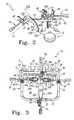
- FIG. 2is a side view of the surgical instrumentation system and spinal column segment of FIG. 1 looking medially toward the spine.
- FIG. 3is a view looking down at the surgical instrumentation system of FIG. 1 along the approach formed to the spine with it.
- FIG. 4is an elevation view of the surgical instrumentation system of FIG. 1 looking cephaladly along the spine.
- FIG. 5is the view of FIG. 4 showing anchors attaching the cephalad and caudal distractor mechanisms to vertebrae of the spine.
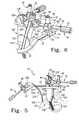
- FIG. 6is a perspective view of the medial retractor and caudal distractor mechanism of the surgical instrumentation system of FIG. 1 .
- FIG. 7is a perspective view of a proximal portion of a retractor portion of the distractor mechanism comprising a portion of the surgical instrumentation system.
- FIG. 8is a perspective view looking at a distal end of the retractor portion of the distractor mechanism of the surgical instrumentation system.
- FIG. 9is a sectional view of an adjustment mechanism engaged with a proximal portion of a distractor blade comprising a portion of the surgical instrumentation system.
- FIG. 10is an enlarged view of a proximal end of the adjustment mechanism of FIG. 9 .
- FIG. 11is a sectional view of the connection of the adjustment mechanism with the retractor portion of the distractor mechanism.
- FIG. 12is a perspective view of one embodiment bone anchor.
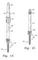
- FIG. 13is a perspective view of a driving instrument assembly engaged to the bone anchor of FIG. 12 .
- FIG. 14is a perspective view of the engagement of the driving instrument assembly with the bone anchor.
- FIG. 15is a perspective view with an extender of the driving instrument assembly attached to the bone anchor and a driver instrument of the driving instrument assembly removed.
- FIG. 16is a section view of a clamping device comprising a portion of the surgical instrumentation system.
- the surgical instrumentation system 10 illustrated in the figuresis adapted to enable a surgeon to effect retraction and shifting aside of soft tissues, muscles, and vessels so as to clear an operating area on the spine while simultaneously maintaining a distraction of adjacent bony portions, such as adjacent vertebrae, of the spinal column.
- Surgical instrumentation system 10provides an operative approach to the spine for a subsequent surgical intervention such as, for example, to installing spinal prostheses or stabilization systems in a disc space between adjacent vertebrae or exteriorly between vertebrae.
- surgical instrumentation system 10provides a posterior lateral operative approach in order to, for example, provide access to the disc space for distraction, removal of disc material and bone material, and insertion of spinal implants.
- Surgical instrumentation system 10also has application in other approaches to the spinal column to provide access to one or more spinal disc spaces or bony structures of the vertebrae.
- Surgical instrumentation system 10is shown in one operative orientation relative to a spinal column segment S in FIGS. 1-6 .
- the spinal column segment Sincludes vertebrae V 1 , V 2 with disc space D 1 therebetween; vertebrae V 2 , V 3 with disc space D 2 therebetween; vertebrae V 3 , V 4 with disc space D 3 therebetween; and vertebrae V 4 , V 5 with disc space D 4 therebetween.
- Spinal column segment Scan comprise the lumbar region of the spine; however, it is contemplated that surgical instrumentation system includes applications in other regions of the spine, including the thoracic, cervical and sacral regions.
- Surgical instrumentation system 10is further shown positioned relative to spinal column segment S to provide access to disc space D 3 between vertebrae V 3 , V 4 , which can correspond to the L3 and L4 vertebrae.
- Surgical instrumentation system 10can also be positioned to provide access to one or more disc spaces, to disc spaces between other vertebrae of the spine, and in operative orientations other than a posterior-lateral approach.
- Surgical instrumentation system 10comprises a frame 20 having at least one of two retractors 120 and 220 and a pair of distractor mechanisms 320 releasably attachable thereto.
- Each retractor 120 and 220includes a blade portion 122 and 221 , respectively, for shifting aside soft tissues and blood vessels.
- Distractor mechanisms 320are mounted to respective vertebrae of spinal column segment S, and may include a retractor portion 332 adapted to contact and retract adjacent tissue.
- retractor 120In its illustrated operative position relative to the patient for a posterior lateral approach, retractor 120 is positioned medially adjacent the midline or posterior elements of the spinal column segment S, and retractor 220 is positioned laterally or postero-laterally relative to the spinal column segment S.
- retractor 220is not provided, but rather a single medial retractor 120 is provided and attached to frame 20 .
- surgical instrumentation system 10includes a pair of distraction mechanisms 320 secured to respective ones of the vertebrae V 3 , V 4 .
- Distraction mechanisms 320can be movable attached to frame 20 .
- distraction mechanisms 320can be secured to vertebrae V 3 , V 4 with anchors 100 engaged to respective ones of vertebrae V 3 , V 4 .
- anchors 100are multi-axial screws engaged in the pedicles of the vertebrae V 3 , V 4 .
- anchors 100can be engaged to other portions of vertebrae V 3 , V 4 , such as the facets, the anterior portion of the vertebral body, or any posterior elements of the vertebrae.
- Anchors 100can be engaged bi-cortically or uni-cortically to bony elements, or to soft tissue elements.
- frame 20includes a lateral member 21 , a caudal member 23 , a medial member 25 , and a cephalad member 27 .
- At least one recess 22 , 24 , 26 , 28is formed in each of the members 21 , 23 , 25 , 27 to accommodate attachment of a clamping device 40 thereto, as discussed further below.
- Each retractor 120 , 220 and distractor mechanism 320is attached to frame 20 by a respective one of the clamping mechanisms 40 and adjustment mechanisms 70 , as discussed further below.
- Members 21 , 23 , 25 , 27can be integrally formed with one another to provide frame 20 in the form of a ring which completely encircles an opening 30 . Opening 30 is sized to accommodate placement of the retractors 120 , 220 and distractor mechanisms 320 therein while also providing space to access the surgical site through the operative approach formed between the retractors 120 , 220 and distractor mechanisms 320 .
- frame 20includes lateral member 21 that lies in plane P 1 and medial member 25 that lies in plane P 2 .
- Plane P 2forms angle A with plane P 1 .
- medial member 25extends along the posterior side of the patient while lateral member 21 extends along the posterior-lateral side of the patient.
- Angle Aallows the members 21 , 25 of frame 20 to follow the patient anatomy, and also allows optimal positioning of retractors 120 , 220 on the frame and relative to the patient to provide a posterior lateral access path to the spinal disc space.
- angle Ais about 30 degrees.
- Caudal and cephalad members 23 , 27are parallel and extend between lateral and medial members 21 , 25 and provide a transition between planes P 1 and P 2 .
- Other embodimentscontemplate angle A ranging from 0 degrees to 90 degrees.
- cephalad member 27 and caudal member 23include at least a portion lying in plane P 2 , allowing attachment of distraction mechanisms 320 to frame 20 in the same plane as medial retractor 120 .
- distraction mechanisms 320can maintain a distraction provided between vertebrae V 3 and V 4 to restore disc space D 3 to a desired disc space height.
- Such distractioncan be achieved with a distraction instrument positioned in the disc space prior to securing distraction mechanisms 320 to frame 20 .
- Such distractioncan also be achieved by applying distraction forces to anchors 100 either directly, or through extensions coupled to anchors 100 prior to securement of distraction mechanisms 320 to frame 20 .
- the laterally positioned retractor 220can be eliminated, and tissue retraction along the posterior lateral side is maintained by the tissue displacement provided by and between the laterally oriented sides of distraction mechanisms 320 .
- Frame 20can also be provided in a form in which each member thereof lies in the same plane. Other shapes for frame 20 are also contemplated. For example, frame 20 can be circular, rectangular, square, elliptical or U-shaped. In embodiments eliminating retractor 220 , frame 20 can be provided with an open side formed by omitting lateral member 21 , for example.
- Frame 20may further be provided with one or more brackets 32 to enable the surgeon to attach frame 20 to an arm secured to the surgical table to support instrumentation system 10 in its operative position. In the illustrated embodiment, a bracket 32 is provided at each corner of frame 20 positioned along the spinal mid-line.
- Medial retractor 120includes an elongated blade portion 122 extending proximally from a distal end portion 124 .
- Blade portion 122can include a relatively flat profile along its medially oriented tissue contacting surface and its opposite laterally oriented surface which extends along the operative approach to the spinal column. However, curved surfaces are also contemplated.
- Distal end portion 124is curved medially from blade portion 122 , and is positionable along or against the posterior bony structures of the vertebrae, such as the spinous processes.
- Blade portion 122includes a width that retains tissue, and vessels away from the approach formed between the retractors and distractor mechanisms of surgical instrumentation system 10 .
- Blade portion 122is generally linear along its longitudinal axis between distal end portion 124 and proximal end portion 126 .
- Proximal end portion 126is offset from and extends generally parallel to blade portion 122 .
- Proximal end portion 126is offset laterally relative to blade portion 122 to facilitate placement of blade portion 122 and distal end portion 124 more medially relative to the operative approach when proximal end portion 126 is coupled to frame 20 .
- Proximal end portion 126includes flanges 128 for engaging adjustment mechanism 70 , as discussed further below.
- Retractor 220similarly includes flanges 228 at its proximal end for engaging an adjustment mechanism 70 .
- Lateral retractor 220is formed by an elongate blade portion 221 extending along longitudinal axis 225 .
- Blade portion 221includes a lower laterally oriented tissue contacting surface 222 concavely curved along longitudinal axis 225 and positionable against the tissue to be retracted.
- Blade portion 221 of retractor 220includes an opposite medially oriented support surface 224 convexly curved along longitudinal axis 225 .
- Support surface 224is oriented toward the operative approach formed by surgical instrumentation system 10 . As shown in FIG.
- support surface 224 of retractor 220includes a concave curvature across its width and transversely to longitudinal axis 225 , forming a slight U-shape that can accommodate and support surgical instruments positioned therealong.
- Retractor 220further includes a lower distal end portion 226 tapering in width along longitudinal axis 225 toward the distal tip of blade portion 221 to minimize its intrusion into the surrounding tissue.
- the curvature of blade portion 221 of lateral retractor 220also positions its distal end away from the access opening formed into the disc space, providing greater tissue retraction in this area and additional room to accommodate placement of surgical instruments, implants and devices between and along the vertebrae.
- Surgical instrumentation system 10includes distraction mechanisms 320 mountable to respective ones of the cephalad and caudal members 27 , 23 of frame 20 and also to respective ones of the anchors 100 .
- Distractor mechanisms 320each include retractor portion 332 mountable to an anchor extension 142 extending from respective ones of the anchors 100 .
- retractor portion 332includes a tissue contacting surface 340 that is convexly curved between the opposite lateral sides 344 , 345 of retractor portion 332 .
- Retractor portion 332includes an opposite surface 349 , which includes a pair of arms 334 , 335 projecting therefrom and extending therealong that form a receptacle 336 therebetween.
- Arms 334 , 335can each define a concave inner surface and outer ends that project toward one another to provide receptacle 336 with a form that slidably captures anchor extension 142 therein.
- Retractor portion 332further includes a proximal end adapted to be pivotally coupled with adjustment mechanism 70 , as shown in FIGS. 9-11 .
- this configurationincludes flanges 328 projecting from tissue contacting surface 340 in a direction opposite arms 334 , 335 .
- Each flange 328includes an arcuate slot 326 extending therethrough and aligned with one another to receive a pin to pivotally couple retractor portion 332 to adjustment mechanism 70 .
- Slots 326define a range of positions along which distractor mechanism 320 can be repositioned relative to the vertebra to which it is coupled.
- An engagement member 324is positioned between flanges 328 , and includes a number of teeth 325 along a convexly curved surface thereof for selective and locking engagement with adjustment mechanism 70 , as discussed further below.
- Adjustment mechanisms 70provide a pivotal coupling arrangement with each of the retractors 120 , 220 and distractor mechanisms 320 that facilitates pivotal adjustment of the retractors 120 , 220 and distractor mechanisms 320 in their operative position in the patient. Adjustment mechanism 70 will be described with reference to distractor mechanisms 320 , it being understood that retractors 120 , 220 may include a similar proximal end configuration with flanges for coupling with the adjustment mechanism 70 extending therefrom.
- Adjustment mechanism 70includes an adjustment handle 72 and a shaft assembly 74 extending from adjustment handle 72 toward distractor mechanism 320 .
- Shaft assembly 74extends to a coupling assembly 76 opposite adjustment handle 72 .
- Coupling assembly 76includes side plates 94 having upper and lower abutment rollers 92 extending therebetween.
- a pivot roller 90extends between plates 96 , and also through slots 326 of flanges 328 of retractor portion 332 . Pivot roller 90 pivotally couples retractor portion 332 to a distal end of adjustment mechanism 70 .
- Shaft assembly 74includes an outer shaft 84 and an inner shaft 85 positioned therethrough.
- Inner shaft 85includes an engagement member 87 at a distal portion thereof.
- Engagement member 87includes a number of teeth 89 at a distal end thereof that interdigitate with teeth 325 of engagement member 324 of retractor portion 332 .
- the distal end of engagement member 87includes a concave profile adapted to receive the convexly curved profile of the adjacent surface of engagement member 324 .
- the interdigitating concave-convex surfacesfacilitate locking a position of retractor portion 332 after pivoting movement of retractor portion 332 , as indicated by arrows 327 , when engagement members 87 , 324 are disengaged from one another.
- engagement member 87can then be engaged to engagement member 324 at any one of a number of positions defined by the interdigitating teeth 89 , 325 .
- the concave-convex mating surface profilesallow all of the teeth to interdigitate in the engaged position at any orientation of distractor mechanism 320 , providing rigidity between the adjustment mechanism 70 and the retractor or distractor mechanism to which it is engaged.
- the rigidity of the engagement between adjustment mechanism 70 and distractor mechanism 320is further enhanced by abutment rollers 92 contacting the ends of the adjacent flanges 328 and with pivot roller 90 restraining flange members 328 therebetween.
- engagement member 87includes a slot 88 through which pivot roller 90 extends. Pivot roller 90 is free to travel longitudinally along slot 88 as engagement member 87 and inner shaft 85 are longitudinally moved with adjustment handle 72 . Accordingly, adjustment handle 72 is operable to selectively release and engage engagement member 87 with engagement member 324 .
- adjustment handle 72includes an internal cavity 78 that receives a linking member 80 .
- Adjustment handle 72is threadingly engaged to a proximal portion of linking member 80 , and can be locked thereto with a locking thread configuration, epoxy or other suitable locking arrangement.
- a distal portion of linking member 80is rotatably positioned about a proximal end of outer shaft 84 .
- a number of bearings 82rotatably couple linking member 80 and adjustment handle 72 about outer shaft 84 .
- Linking member 80further includes an inner passage extending therethrough, which is configured along the proximal portion of linking member 80 to threadingly engage a proximal end 86 of inner shaft 85 .
- Adjustment handle 72 and linking member 80can be rotated about the proximal end 86 of inner shaft 85 .
- the threaded engagement between inner shaft 85 and linking member 80moves inner shaft 85 , and thus engagement member 87 , distally and proximally in accordance with the particular thread turn provided between inner shaft 85 and linking member 80 .
- Engagement member 87can accordingly be moved along roller 90 and into and out of engagement with engagement member 324 in accordance with the direction of rotation of adjustment handle 72 .
- retractor portion 332includes a distal end configured to receive a proximal end of anchor 100 therein such that retractor portion 332 is fixedly secured to anchor 100 .
- anchor 100is shown as a multi-axial screw having a lower threaded shaft 102 for engaging bony structure and a proximal head 104 .
- the proximal portion of anchor 100can comprise a yoke 106 pivotally coupled to head 104 .
- Yoke 106includes a pair of arms 108 , 110 defining a U-shaped passage 112 therebetween to receive a stabilization device, such as a spinal rod or tether. Arms 108 , 110 can further be internally threaded to receive a set screw to retain the stabilization device in passage 112 .
- Socket portion 338is formed by distal ends 346 , 347 of respective ones of the arms 334 , 335 , and by distal extensions 341 , 343 of the outer portions of arms 334 , 335 .
- Distal extensions 341 , 343are recessed relative to arms 334 , 335 along receptacle 336 so that arms 108 , 110 of yoke 106 can be positioned in socket portion 338 with passage 112 remaining substantially unobstructed.
- arms 108 , 110form an extension of the adjacent arm 334 , 335 , and passage 112 is aligned with receptacle 336 .
- the yoke 106is firmly and non-pivotally seated in socket portion 338 , while yoke 106 is allowed to pivot relative to shaft 102 .
- Retractor portion 332further includes a distal lip 349 extending distally of socket portion 338 and positionable along seat 114 of yoke 106 .
- anchor extension 142may comprise a portion of a driving instrument assembly that can be engaged to anchor 100 to facilitate engagement of anchor 100 to the bony structure.
- a driving instrument assembly 140is engaged to anchor 100 , and is operable by the surgeon to engage threaded shaft 102 to a bony structure.
- Threaded shaft 102can be provided in a form suitable for self-drilling into the bone during placement, for self-tapping a pre-drilled bore, or for positioning in a pre-drilled and pre-tapped bore in the bony structure.
- Driving instrument assembly 140includes a cylindrical anchor extension 142 and driver instrument 150 removably positioned through a longitudinal passage of anchor extension 142 .
- Anchor extension 142includes a distal extension 148 threadingly engageable between arms 108 , 110 of yoke 106 .
- Driving instrument 150includes a driving instrument coupler 144 to facilitate attachment and removal of driving instrument 150 to anchor extension 142 .
- Driving instrument 150includes a shaft 152 extending through and rotatably coupled to a sleeve 154 of coupler 144 with a number of bearings. Shaft 152 is further allowed to axially translate relative to coupler 144 and anchor extension 142 within a limited range defined by the interconnection between shaft 152 and sleeve 154 .
- Driving instrument 150includes a proximal extension 152 with a tool engagement portion at a proximal end thereof. As shown in FIG. 14 , driving instrument 150 includes a distal end 156 projecting from anchor extension 142 for engaging a tool recess in head 104 of anchor 100 .
- driving instrument 150is inserted through and engaged to anchor extension 142 , and its distal end 156 is positioned in the tool recess in head 104 of anchor 100 .
- Anchor extension 142is threadingly engaged to yoke 106 .
- Driving instrument 150is rotatable relative to anchor extension 142 with a driving instrument engaged to the proximal end of shaft 152 .
- driving instrument 150can be removed from anchor extension 142 by detaching coupler 144 from anchor extensions 142 .
- Retractor portion 332 of distraction mechanism 320can then be loaded onto anchor extension 142 with anchor extension 142 in receptacle 336 .
- Retractor portion 332can be secured to anchor extension 142 with a second coupling member 160 engaged to proximal end 147 of anchor extension 142 ( FIGS. 1-6 and 15 .) Coupling member 160 contacts the proximal end of retractor portion 332 to push and retain socket portion 338 into contact with yoke 106 of anchor 100 and firmly couple the retractor portion 332 thereto. However, yoke 106 can still be pivoted relative to shaft portion 102 of anchor 100 , permitting distractor mechanism 320 to be pivotally adjustable in position relative to the vertebra to which it is mounted.
- Anchor extension 142is provided with a proximal tool engagement portion 149 to facilitate removal of anchor extension 142 from anchor 100 if necessary.
- distractor mechanism 320does not include a retractor portion 332 , but rather the anchor extension portion of the distractor mechanism contacts and retracts the adjacent tissue.
- Such a modified distractor mechanismcan be employed with frame 20 with an opposite distractor mechanism, and a medial retractor 120 alone or in combination with a lateral retractor 220 .
- clamping device 40In order to secure retractors 120 , 220 and distractor mechanisms 320 to frame 20 , a number of clamping devices 40 are provided that releasably engage the corresponding adjustment mechanism 70 extending from the retractors 120 , 220 and distractor mechanisms 320 .
- clamping device 40includes a foot portion 50 slidably positioned along the respective member of frame 20 .
- Foot portion 50includes first and second arms 51 , 55 defining a receptacle therebetween.
- Arm 51includes a recessed undercut portion 53 shaped to receive an undercut portion 34 of frame 20 to mount foot portion 50 thereto. The interface between foot portion 50 and undercut portion 34 prevents clamping device 40 from pivoting or lifting from frame 20 .
- Foot portion 50is positionable on the corresponding member 21 , 23 , 25 , 27 by placing foot portion 50 on frame 20 at the corresponding recess 22 , 24 , 26 , 28 . Foot portion 50 , and thus clamping device 40 , can be slid along the corresponding frame member 21 , 23 , 25 , 27 to the desired location therealong where the receptacle between arms 51 , 55 is located along the corresponding undercut portion 34 .
- clamping device 40includes a mounting post 44 extending from foot portion 50 , and an inner clamping sleeve 42 positioned about mounting post 44 .
- Clamping sleeve 42includes an upper threaded attachment portion 52 and a lower clamping portion 54 .
- Lower clamping portion 54includes a frusto-conically shaped lower support member 56 extending thereabout, and at least one slot extending axially through support member 56 to divide clamping portion 54 into a corresponding number of fingers. Accordingly, the fingers of clamping portion 54 can be compressed about mounting post 44 to selectively grip and release mounting post 44 therebetween. Accordingly, clamping sleeve 42 can be axially translated relative to mounting post 44 and clamped at any one of a number of positions therealong to provide elevational adjustment of the respective retractor 120 , 220 or distractor mechanism 320 engaged thereto.
- a coupler 48is positionable about clamping sleeve 42 , and is supported on a contact surface 62 of lower support member 56 .
- Coupler 48includes a relief slot 58 formed therein that divides coupler 48 into upper and lower clamping halves 61 , 63 joined by an integral hinge.
- An enlarged receptacle 60is provided along one side of coupling member 48 in communication with relief slot 58 that is sized to receive shaft assembly 74 of adjustment mechanism 70 therethrough.
- a clamping nut 46is threadingly engaged to attachment portion 52 , and movable therealong to contact coupling member 48 .
- coupler 48As clamping nut 46 is threaded downwardly, it contacts coupler 48 to flex clamping halves 61 , 63 toward one another, gripping shaft assembly 74 therebetween in receptacle 60 .
- coupler 48includes lower contact surface 64 that presses on contact surface 62 to compress clamping portion 54 of clamping sleeve 42 to mounting post 44 .
- Receptacle 60can be configured to capture shaft assembly 74 therein to prevent shaft assembly 74 from slipping laterally therefrom.
- clamping device 40allows adjustment mechanism 70 and the retractor 120 , 220 or distractor mechanism 320 to be repositioned relative to frame 20 .
- clamping nut 46When clamping nut 46 is loosened, retractors 120 , 220 can be disengaged from adjustment mechanism 70 and pivoted, moved toward the center of frame 20 , and/or moved away from the center of frame 20 . Clamping nut 46 can then be re-engaged to secure the re-positioned shaft assembly 74 in receptacle 60 .
- Coupler 48 and clamping sleeve 42can further be repositioned or translated up and down along the length of mounting post 44 to accommodate re-positioning of retractors 120 , 220 and distractor mechanisms 320 in the patient.
- distractor mechanisms 320the arrangement between the distractor mechanism and anchor, adjustment mechanism, and clamping device can provide a suitably rigid coupling arrangement to maintain distraction of the adjacent vertebrae when distraction devices are removed from the disc space.
- One technique for using surgical instrumentation system 10includes the surgeon making an incision in the skin of the patient to provide access to the facet joints of adjacent vertebrae in a posterior lateral approach.
- Retractor 120can be placed in the incision to assist in exposing and identifying the underlying bony structure.
- Frame 20can then be placed around retractor 120 , and retractor 220 if employed.
- Adjustment mechanisms 70 extending from retractors 120 , 220can be engaged to clamping devices 40 to maintain and provide for adjustment of the retracted condition of the skin and tissue.
- Anchors 100are engaged to adjacent vertebrae, and anchor extensions 142 are coupled to corresponding ones of the anchors 100 as discussed above.
- Anchors 100are engaged to bony structure of the vertebrae positioned on each side of the target disc space.
- anchors 100can be engaged in the pedicles of the adjacent vertebrae.
- the multi-axial heads on anchors 100allow anchor extensions 142 to be oriented relative to anchors 100 for attachment to the respective portions of frame 20 . If employed, retractor portions 332 are then engaged to anchors 100 by sliding retractor portions 332 along the respective anchor extension 142 , and engaging retractor portions 332 to the anchor extensions 142 with coupling members 160 .
- the disc spacecan be distracted with appropriate distraction or spreading instruments.
- distractor mechanisms 320can be pivoted relative to the vertebra to which it is mounted. Adjustment mechanisms 70 extending from distractor mechanisms 320 can then be secured to frame 20 with clamping devices 40 when suitably positioned and oriented in the incision. Adjustment mechanisms 70 are then engaged to the respective clamping devices 40 to maintain the distracted disc space condition and retracted tissue condition.
- Retractors 120 , 220 and distractor mechanisms 320can be adjusted in the desired angular and elevational orientation by means of the adjustment mechanisms 70 and clamping devices 40 . The positioning of retractors 120 , 220 and distractor mechanisms 320 may be facilitated by the use of push members, handles or the like.
- the retractors 120 , 220 and distractor mechanisms 320can be made of a material which permits effecting a radiographic monitoring during the operation, i.e. a material which is radio-transparent or radio-translucid. It is also contemplated that this material be selected, for example, from the following group: aluminum, titanium, stainless steel, carbon composites, and plastics.
Landscapes
- Health & Medical Sciences (AREA)
- Neurology (AREA)
- Orthopedic Medicine & Surgery (AREA)
- Life Sciences & Earth Sciences (AREA)
- Surgery (AREA)
- Heart & Thoracic Surgery (AREA)
- Engineering & Computer Science (AREA)
- Biomedical Technology (AREA)
- Nuclear Medicine, Radiotherapy & Molecular Imaging (AREA)
- Medical Informatics (AREA)
- Molecular Biology (AREA)
- Animal Behavior & Ethology (AREA)
- General Health & Medical Sciences (AREA)
- Public Health (AREA)
- Veterinary Medicine (AREA)
- Surgical Instruments (AREA)
- Orthopedics, Nursing, And Contraception (AREA)
- Prostheses (AREA)
Abstract
Description
Claims (28)
Priority Applications (1)
| Application Number | Priority Date | Filing Date | Title |
|---|---|---|---|
| US10/720,656US8100828B2 (en) | 2002-11-23 | 2003-11-24 | Distraction and retraction system for spinal surgery |
Applications Claiming Priority (2)
| Application Number | Priority Date | Filing Date | Title |
|---|---|---|---|
| US42880002P | 2002-11-23 | 2002-11-23 | |
| US10/720,656US8100828B2 (en) | 2002-11-23 | 2003-11-24 | Distraction and retraction system for spinal surgery |
Publications (2)
| Publication Number | Publication Date |
|---|---|
| US20040230191A1 US20040230191A1 (en) | 2004-11-18 |
| US8100828B2true US8100828B2 (en) | 2012-01-24 |
Family
ID=32393455
Family Applications (1)
| Application Number | Title | Priority Date | Filing Date |
|---|---|---|---|
| US10/720,656Expired - LifetimeUS8100828B2 (en) | 2002-11-23 | 2003-11-24 | Distraction and retraction system for spinal surgery |
Country Status (7)
| Country | Link |
|---|---|
| US (1) | US8100828B2 (en) |
| EP (1) | EP1567064B1 (en) |
| JP (1) | JP4708794B2 (en) |
| AT (1) | ATE556658T1 (en) |
| AU (1) | AU2003295934B2 (en) |
| CA (1) | CA2506357C (en) |
| WO (1) | WO2004047650A2 (en) |
Cited By (41)
| Publication number | Priority date | Publication date | Assignee | Title |
|---|---|---|---|---|
| US20110130793A1 (en)* | 2009-11-10 | 2011-06-02 | Nuvasive Inc. | Method and apparatus for performing spinal surgery |
| US20110130634A1 (en)* | 2009-05-20 | 2011-06-02 | Synthes Usa, Llc | Patient-mounted retraction |
| US20120265021A1 (en)* | 2011-04-13 | 2012-10-18 | Nottmeier Eric W | Anterior Cervical Retractor System |
| US20120296433A1 (en)* | 2010-02-02 | 2012-11-22 | Azadeh Farin | Spine surgery device |
| US8535318B2 (en) | 2010-04-23 | 2013-09-17 | DePuy Synthes Products, LLC | Minimally invasive instrument set, devices and related methods |
| US8636655B1 (en) | 2010-01-19 | 2014-01-28 | Ronald Childs | Tissue retraction system and related methods |
| US20140324055A1 (en)* | 2013-04-29 | 2014-10-30 | Gehring Cut Ag | Method and apparatus for the removal of intervertebral discs |
| US9066701B1 (en) | 2012-02-06 | 2015-06-30 | Nuvasive, Inc. | Systems and methods for performing neurophysiologic monitoring during spine surgery |
| US9314274B2 (en) | 2011-05-27 | 2016-04-19 | DePuy Synthes Products, Inc. | Minimally invasive spinal fixation system including vertebral alignment features |
| US9486133B2 (en) | 2010-08-23 | 2016-11-08 | Nuvasive, Inc. | Surgical access system and related methods |
| US9498262B2 (en) | 2006-04-11 | 2016-11-22 | DePuy Synthes Products, Inc. | Minimally invasive fixation system |
| US9655505B1 (en) | 2012-02-06 | 2017-05-23 | Nuvasive, Inc. | Systems and methods for performing neurophysiologic monitoring during spine surgery |
| US9675389B2 (en) | 2009-12-07 | 2017-06-13 | Samy Abdou | Devices and methods for minimally invasive spinal stabilization and instrumentation |
| US9757067B1 (en) | 2012-11-09 | 2017-09-12 | Nuvasive, Inc. | Systems and methods for performing neurophysiologic monitoring during spine surgery |
| US20170273679A1 (en)* | 2006-06-06 | 2017-09-28 | Globus Medical, Inc. | Surgical retractor system |
| US9795370B2 (en) | 2014-08-13 | 2017-10-24 | Nuvasive, Inc. | Minimally disruptive retractor and associated methods for spinal surgery |
| US9795367B1 (en) | 2003-10-17 | 2017-10-24 | Nuvasive, Inc. | Surgical access system and related methods |
| DE102016118718A1 (en) | 2016-10-04 | 2018-04-05 | Zbigniew Combrowski | Surgical instrument |
| US10045768B2 (en) | 2014-07-06 | 2018-08-14 | Javier Garcia-Bengochea | Methods and devices for surgical access |
| US10238375B2 (en) | 2017-07-19 | 2019-03-26 | Nuvasive, Inc. | Surgical retractor |
| US10363022B2 (en) | 2017-10-18 | 2019-07-30 | Spine Wave, Inc. | Screw based retractor with expandable blades |
| US10499897B2 (en) | 2017-03-06 | 2019-12-10 | Thompson Surgical Instruments, Inc. | Distractor with bidirectional ratchet |
| US10548740B1 (en) | 2016-10-25 | 2020-02-04 | Samy Abdou | Devices and methods for vertebral bone realignment |
| US10575961B1 (en) | 2011-09-23 | 2020-03-03 | Samy Abdou | Spinal fixation devices and methods of use |
| US10653407B2 (en) | 2016-12-21 | 2020-05-19 | Nuvasive, Inc. | Surgical retractor |
| US10687830B2 (en) | 2015-07-06 | 2020-06-23 | Javier Garcia-Bengochea | Methods and devices for surgical access |
| US10695105B2 (en) | 2012-08-28 | 2020-06-30 | Samy Abdou | Spinal fixation devices and methods of use |
| US10857003B1 (en) | 2015-10-14 | 2020-12-08 | Samy Abdou | Devices and methods for vertebral stabilization |
| US10918498B2 (en) | 2004-11-24 | 2021-02-16 | Samy Abdou | Devices and methods for inter-vertebral orthopedic device placement |
| US10973648B1 (en) | 2016-10-25 | 2021-04-13 | Samy Abdou | Devices and methods for vertebral bone realignment |
| US11006982B2 (en) | 2012-02-22 | 2021-05-18 | Samy Abdou | Spinous process fixation devices and methods of use |
| US11154288B1 (en) | 2011-05-10 | 2021-10-26 | Nuvasive, Inc. | Method and apparatus for performing spinal fusion surgery |
| US11173040B2 (en) | 2012-10-22 | 2021-11-16 | Cogent Spine, LLC | Devices and methods for spinal stabilization and instrumentation |
| US11179248B2 (en) | 2018-10-02 | 2021-11-23 | Samy Abdou | Devices and methods for spinal implantation |
| US11317902B2 (en) | 2017-06-15 | 2022-05-03 | DePuy Synthes Products, Inc. | SST retractor with radiolucent feature |
| US11413028B2 (en) | 2017-10-18 | 2022-08-16 | Spine Wave, Inc. | Screw-based retractor having arms with plural discrete selectively lockable positions |
| US11484349B2 (en)* | 2017-02-17 | 2022-11-01 | Warsaw Orthopedic, Inc. | Surgical system and method |
| US20220346766A1 (en)* | 2018-10-24 | 2022-11-03 | Stryker European Operations Holdings Llc | Anterior to Psoas Instrumentation |
| US12207811B2 (en) | 2022-05-24 | 2025-01-28 | Globus Medical, Inc. | TLIF distraction and retraction |
| US12295624B2 (en) | 2022-05-24 | 2025-05-13 | Globus Medical, Inc. | TLIF distraction and retraction |
| US12440248B2 (en) | 2022-06-28 | 2025-10-14 | DePuy Synthes Products, Inc. | Minimally invasive instrument set, devices, and related methods |
Families Citing this family (153)
| Publication number | Priority date | Publication date | Assignee | Title |
|---|---|---|---|---|
| EP1417000B1 (en) | 2001-07-11 | 2018-07-11 | Nuvasive, Inc. | System for determining nerve proximity during surgery |
| JP2005503857A (en) | 2001-09-25 | 2005-02-10 | ヌバシブ, インコーポレイテッド | Systems and methods for performing surgical procedures and surgical diagnosis |
| JP3913506B2 (en)* | 2001-09-26 | 2007-05-09 | 三洋電機株式会社 | Disc recording or playback device with a tray that can be moved up and down |
| US7582058B1 (en) | 2002-06-26 | 2009-09-01 | Nuvasive, Inc. | Surgical access system and related methods |
| US6945933B2 (en)* | 2002-06-26 | 2005-09-20 | Sdgi Holdings, Inc. | Instruments and methods for minimally invasive tissue retraction and surgery |
| US7473222B2 (en)* | 2002-06-26 | 2009-01-06 | Warsaw Orthopedic, Inc. | Instruments and methods for minimally invasive tissue retraction and surgery |
| US9259144B2 (en) | 2002-07-11 | 2016-02-16 | Nuvasive, Inc. | Surgical access system and related methods |
| EP1558184A2 (en)* | 2002-10-08 | 2005-08-03 | SDGI Holdings, Inc. | Insertion device and techniques for orthopaedic implants |
| US8137284B2 (en) | 2002-10-08 | 2012-03-20 | Nuvasive, Inc. | Surgical access system and related methods |
| US6849064B2 (en)* | 2002-10-25 | 2005-02-01 | James S. Hamada | Minimal access lumbar diskectomy instrumentation and method |
| US7887482B2 (en)* | 2002-10-25 | 2011-02-15 | K2M, Inc. | Minimal access lumbar diskectomy instrumentation and method |
| US7850608B2 (en)* | 2002-10-25 | 2010-12-14 | K2M, Inc. | Minimal incision maximal access MIS spine instrumentation and method |
| US7935054B2 (en)* | 2002-10-25 | 2011-05-03 | K2M, Inc. | Minimal access lumbar diskectomy instrumentation and method |
| US7946982B2 (en)* | 2002-10-25 | 2011-05-24 | K2M, Inc. | Minimal incision maximal access MIS spine instrumentation and method |
| US7691057B2 (en) | 2003-01-16 | 2010-04-06 | Nuvasive, Inc. | Surgical access system and related methods |
| AU2004212942A1 (en) | 2003-02-14 | 2004-09-02 | Depuy Spine, Inc. | In-situ formed intervertebral fusion device |
| JP4463819B2 (en) | 2003-09-25 | 2010-05-19 | ヌヴァシヴ インコーポレイテッド | Surgical access system |
| US7905840B2 (en) | 2003-10-17 | 2011-03-15 | Nuvasive, Inc. | Surgical access system and related methods |
| US7967826B2 (en) | 2003-10-21 | 2011-06-28 | Theken Spine, Llc | Connector transfer tool for internal structure stabilization systems |
| US7588575B2 (en) | 2003-10-21 | 2009-09-15 | Innovative Spinal Technologies | Extension for use with stabilization systems for internal structures |
| US7588588B2 (en) | 2003-10-21 | 2009-09-15 | Innovative Spinal Technologies | System and method for stabilizing of internal structures |
| US8038611B2 (en) | 2003-12-18 | 2011-10-18 | Depuy Spine, Inc. | Surgical methods and surgical kits |
| US7776051B2 (en) | 2004-05-03 | 2010-08-17 | Theken Spine, Llc | System and method for displacement of bony structures |
| US7637914B2 (en) | 2004-08-04 | 2009-12-29 | Leslie Stern | Surgical base unit and retractor support mechanism |
| US8460310B2 (en) | 2004-08-04 | 2013-06-11 | Leslie Stern | Surgical base unit and retractor support mechanism |
| US7556600B2 (en) | 2004-09-09 | 2009-07-07 | Zimmer Spine, Inc. | Surgical retraction apparatus and associated methods |
| US7569061B2 (en) | 2004-11-16 | 2009-08-04 | Innovative Spinal Technologies, Inc. | Off-axis anchor guidance system |
| FR2880254B1 (en)* | 2004-12-30 | 2007-11-30 | Neuro France Implants Sarl | IMPLANT DEVICE FOR VERTEBRAL OSTEOSYNTHESIS EQUIPMENT AND TOOL FOR ITS PLACEMENT |
| WO2008024937A2 (en) | 2006-08-23 | 2008-02-28 | Pioneer Surgical Technology, Inc. | Minimally invasive surgical system |
| EP1858422A4 (en)* | 2005-02-23 | 2011-12-28 | Pioneer Surgical Technology Inc | Minimally invasive surgical system |
| US20060200023A1 (en)* | 2005-03-04 | 2006-09-07 | Sdgi Holdings, Inc. | Instruments and methods for nerve monitoring in spinal surgical procedures |
| US20060224044A1 (en)* | 2005-03-31 | 2006-10-05 | Depuy Spine, Inc. | Surgical retractors and methods of use |
| US8366718B2 (en)* | 2005-07-06 | 2013-02-05 | Copf Jr Franz | Preparation device for preparing an intervertebral disc compartment |
| WO2008103781A2 (en) | 2007-02-21 | 2008-08-28 | Benvenue Medical, Inc. | Devices for treating the spine |
| US8366773B2 (en) | 2005-08-16 | 2013-02-05 | Benvenue Medical, Inc. | Apparatus and method for treating bone |
| AU2006279558B2 (en) | 2005-08-16 | 2012-05-17 | Izi Medical Products, Llc | Spinal tissue distraction devices |
| US8911364B2 (en)* | 2005-09-08 | 2014-12-16 | DePuy Synthes Products, LLC | Spine retractor and distractor device |
| US7918792B2 (en)* | 2006-01-04 | 2011-04-05 | Depuy Spine, Inc. | Surgical retractor for use with minimally invasive spinal stabilization systems and methods of minimally invasive surgery |
| US7758501B2 (en) | 2006-01-04 | 2010-07-20 | Depuy Spine, Inc. | Surgical reactors and methods of minimally invasive surgery |
| US7981031B2 (en) | 2006-01-04 | 2011-07-19 | Depuy Spine, Inc. | Surgical access devices and methods of minimally invasive surgery |
| US7955257B2 (en) | 2006-01-05 | 2011-06-07 | Depuy Spine, Inc. | Non-rigid surgical retractor |
| US7985179B2 (en) | 2006-01-23 | 2011-07-26 | Pioneer Surgical Technology | Retraction apparatus and method of use |
| US8876687B2 (en)* | 2006-03-08 | 2014-11-04 | Zimmer Spine, Inc. | Surgical retractor and retractor assembly |
| GB0608561D0 (en)* | 2006-04-29 | 2006-06-07 | Comis Orthopaedics Ltd | Surgical apparatus |
| US8696560B2 (en)* | 2006-05-02 | 2014-04-15 | K2M, Inc. | Minimally open retraction device |
| US8197488B2 (en)* | 2006-10-16 | 2012-06-12 | Depuy Spine, Inc. | Automatic locking casper distractor |
| WO2008070863A2 (en) | 2006-12-07 | 2008-06-12 | Interventional Spine, Inc. | Intervertebral implant |
| EP2124778B1 (en) | 2007-02-21 | 2019-09-25 | Benvenue Medical, Inc. | Devices for treating the spine |
| WO2008131084A2 (en) | 2007-04-17 | 2008-10-30 | K2M, Inc. | Minimally open interbody access retraction device and surgical method |
| US8192463B2 (en) | 2007-05-24 | 2012-06-05 | Mcloughlin Joseph | Surgical retractor and related methods |
| US8900307B2 (en) | 2007-06-26 | 2014-12-02 | DePuy Synthes Products, LLC | Highly lordosed fusion cage |
| US8623019B2 (en) | 2007-07-03 | 2014-01-07 | Pioneer Surgical Technology, Inc. | Bone plate system |
| US8361126B2 (en) | 2007-07-03 | 2013-01-29 | Pioneer Surgical Technology, Inc. | Bone plate system |
| US8852089B2 (en)* | 2007-08-01 | 2014-10-07 | Warsaw Orthopedic, Inc. | Instrumentation for tissue retraction |
| US9232968B2 (en) | 2007-12-19 | 2016-01-12 | DePuy Synthes Products, Inc. | Polymeric pedicle rods and methods of manufacturing |
| EP2237748B1 (en) | 2008-01-17 | 2012-09-05 | Synthes GmbH | An expandable intervertebral implant |
| US8936641B2 (en) | 2008-04-05 | 2015-01-20 | DePuy Synthes Products, LLC | Expandable intervertebral implant |
| US8262570B2 (en) | 2008-05-30 | 2012-09-11 | Pioneer Surgical Technology, Inc. | Retraction apparatus and method of use |
| US8968192B2 (en) | 2008-06-06 | 2015-03-03 | Warsaw Orthopedic, Inc. | Systems and methods for tissue retraction |
| US8226554B2 (en) | 2008-10-30 | 2012-07-24 | Warsaw Orthopedic, Inc. | Retractor assemblies for surgery in a patient |
| US8641734B2 (en) | 2009-02-13 | 2014-02-04 | DePuy Synthes Products, LLC | Dual spring posterior dynamic stabilization device with elongation limiting elastomers |
| US8062218B2 (en)* | 2009-02-27 | 2011-11-22 | Warsaw Orthopedic, Inc. | Surgical access instrument |
| US8535327B2 (en) | 2009-03-17 | 2013-09-17 | Benvenue Medical, Inc. | Delivery apparatus for use with implantable medical devices |
| US9526620B2 (en) | 2009-03-30 | 2016-12-27 | DePuy Synthes Products, Inc. | Zero profile spinal fusion cage |
| US9320543B2 (en) | 2009-06-25 | 2016-04-26 | DePuy Synthes Products, Inc. | Posterior dynamic stabilization device having a mobile anchor |
| US20110098537A1 (en)* | 2009-10-28 | 2011-04-28 | Warsaw Orthopedic, Inc. | Tissue massage retractor |
| US9393129B2 (en) | 2009-12-10 | 2016-07-19 | DePuy Synthes Products, Inc. | Bellows-like expandable interbody fusion cage |
| US9445844B2 (en) | 2010-03-24 | 2016-09-20 | DePuy Synthes Products, Inc. | Composite material posterior dynamic stabilization spring rod |
| US9907560B2 (en) | 2010-06-24 | 2018-03-06 | DePuy Synthes Products, Inc. | Flexible vertebral body shavers |
| US8979860B2 (en) | 2010-06-24 | 2015-03-17 | DePuy Synthes Products. LLC | Enhanced cage insertion device |
| US8623091B2 (en) | 2010-06-29 | 2014-01-07 | DePuy Synthes Products, LLC | Distractible intervertebral implant |
| US8827902B2 (en)* | 2010-08-16 | 2014-09-09 | Donald David DIETZE, Jr. | Surgical instrument system and method for providing retraction and vertebral distraction |
| WO2012034005A2 (en)* | 2010-09-09 | 2012-03-15 | Synthes Usa, Llc | Vertebral adjustment systems for spine alignment |
| US8623022B2 (en)* | 2010-09-20 | 2014-01-07 | Zimmer Spine, Inc. | Surgical instrument support system and method |
| US8449463B2 (en) | 2010-10-08 | 2013-05-28 | K2M, Inc. | Lateral access system and method of use |
| US9402732B2 (en) | 2010-10-11 | 2016-08-02 | DePuy Synthes Products, Inc. | Expandable interspinous process spacer implant |
| US20140107707A1 (en)* | 2011-02-10 | 2014-04-17 | Robert A. Rovner | Table anchored scoliosis de-rotation system and method |
| US8702600B2 (en) | 2011-03-08 | 2014-04-22 | Pioneer Surgical Technology, Inc. | Apparatus and method for enlarging an incision |
| US9579095B2 (en) | 2011-03-08 | 2017-02-28 | Pioneer Surgical Technology, Inc. | Apparatus and method for enlarging an incision |
| US10357239B2 (en) | 2011-03-08 | 2019-07-23 | Pioneer Surgical Technology, Inc. | Apparatus and method for enlarging an incision |
| US8790406B1 (en) | 2011-04-01 | 2014-07-29 | William D. Smith | Systems and methods for performing spine surgery |
| US8974381B1 (en) | 2011-04-26 | 2015-03-10 | Nuvasive, Inc. | Cervical retractor |
| US8900137B1 (en) | 2011-04-26 | 2014-12-02 | Nuvasive, Inc. | Cervical retractor |
| US8814873B2 (en) | 2011-06-24 | 2014-08-26 | Benvenue Medical, Inc. | Devices and methods for treating bone tissue |
| US8636656B2 (en) | 2011-08-16 | 2014-01-28 | Warsaw Orthopedic, Inc. | Retractor assemblies with blade drive mechanisms |
| US9113853B1 (en) | 2011-08-31 | 2015-08-25 | Nuvasive, Inc. | Systems and methods for performing spine surgery |
| US9198769B2 (en) | 2011-12-23 | 2015-12-01 | Pioneer Surgical Technology, Inc. | Bone anchor assembly, bone plate system, and method |
| US9125703B2 (en) | 2012-01-16 | 2015-09-08 | K2M, Inc. | Rod reducer, compressor, distractor system |
| US8852090B2 (en)* | 2012-03-13 | 2014-10-07 | Globus Medical, Inc. | System and method for retracting body tissue |
| US9615728B2 (en) | 2012-06-27 | 2017-04-11 | Camplex, Inc. | Surgical visualization system with camera tracking |
| US9642606B2 (en)* | 2012-06-27 | 2017-05-09 | Camplex, Inc. | Surgical visualization system |
| US9179947B2 (en) | 2012-07-03 | 2015-11-10 | Tedan Surgical Innovations, Llc | Locking distractor with two-start distraction screw |
| EP2684533B1 (en)* | 2012-07-09 | 2016-03-16 | Zimmer Spine | Anchor for attachment to a bony structure |
| WO2014018624A1 (en)* | 2012-07-27 | 2014-01-30 | Spinal Usa, Inc. | Minimally invasive devices, systems and methods for treating the spine |
| WO2014062692A1 (en)* | 2012-10-18 | 2014-04-24 | Deroyal Industries, Inc. | Driver apparatus for a pedicle screw assembly |
| US9084591B2 (en) | 2012-10-23 | 2015-07-21 | Neurostructures, Inc. | Retractor |
| US9717601B2 (en) | 2013-02-28 | 2017-08-01 | DePuy Synthes Products, Inc. | Expandable intervertebral implant, system, kit and method |
| US9522070B2 (en) | 2013-03-07 | 2016-12-20 | Interventional Spine, Inc. | Intervertebral implant |
| US9782159B2 (en) | 2013-03-13 | 2017-10-10 | Camplex, Inc. | Surgical visualization systems |
| US10085783B2 (en) | 2013-03-14 | 2018-10-02 | Izi Medical Products, Llc | Devices and methods for treating bone tissue |
| DE202013004369U1 (en)* | 2013-04-29 | 2014-07-30 | Silony Medical International AG | Screwdrivers for bone screws |
| EP3046458B1 (en) | 2013-09-20 | 2020-10-21 | Camplex, Inc. | Surgical visualization systems |
| US10028651B2 (en) | 2013-09-20 | 2018-07-24 | Camplex, Inc. | Surgical visualization systems and displays |
| EP3054871B1 (en) | 2013-10-07 | 2022-05-18 | K2M, Inc. | Rod reducer |
| CA2874390C (en)* | 2013-12-13 | 2018-03-06 | Stryker European Holdings I, Llc | Tissue retraction and vertebral displacement devices, systems, and methods for posterior spinal fusion |
| US9414828B2 (en) | 2014-05-01 | 2016-08-16 | Blackstone Medical, Inc. | Integrated retractor-distractor system for use with modular bone screws |
| US10426454B2 (en) | 2014-10-21 | 2019-10-01 | Globus Medical, Inc. | Orthopedic tools for implantation |
| EP3226799A4 (en) | 2014-12-05 | 2018-07-25 | Camplex, Inc. | Surgical visualization systems and displays |
| EP3047811B1 (en) | 2015-01-15 | 2022-05-18 | K2M, Inc. | Rod reducer |
| US11426290B2 (en) | 2015-03-06 | 2022-08-30 | DePuy Synthes Products, Inc. | Expandable intervertebral implant, system, kit and method |
| WO2016154589A1 (en) | 2015-03-25 | 2016-09-29 | Camplex, Inc. | Surgical visualization systems and displays |
| EP3288473B1 (en) | 2015-04-30 | 2022-12-28 | K2M, Inc. | Rod reducer |
| US10499894B2 (en) | 2015-08-12 | 2019-12-10 | K2M, Inc. | Orthopedic surgical system including surgical access systems, distraction systems, and methods of using same |
| US10149674B2 (en) | 2015-08-12 | 2018-12-11 | K2M, Inc. | Orthopedic surgical system including surgical access systems, distraction systems, and methods of using same |
| US10022157B2 (en) | 2015-11-20 | 2018-07-17 | Blackstone Medical, Inc. | Convertible screw for spinal fixation |
| WO2017091704A1 (en) | 2015-11-25 | 2017-06-01 | Camplex, Inc. | Surgical visualization systems and displays |
| US10524843B2 (en) | 2016-05-06 | 2020-01-07 | K2M, Inc. | Rotation shaft for a rod reducer |
| US10010350B2 (en) | 2016-06-14 | 2018-07-03 | Stryker European Holdings I, Llc | Gear mechanisms for fixation frame struts |
| US11510788B2 (en) | 2016-06-28 | 2022-11-29 | Eit Emerging Implant Technologies Gmbh | Expandable, angularly adjustable intervertebral cages |
| EP3474784A2 (en) | 2016-06-28 | 2019-05-01 | Eit Emerging Implant Technologies GmbH | Expandable and angularly adjustable intervertebral cages with articulating joint |
| AU2017235887B2 (en) | 2016-09-26 | 2021-09-30 | K2M, Inc. | Retraction system and method of use |
| US10786328B2 (en)* | 2016-10-26 | 2020-09-29 | Thompson Surgical Instruments, Inc. | Adaptor handle for surgical retractor |
| US10888433B2 (en) | 2016-12-14 | 2021-01-12 | DePuy Synthes Products, Inc. | Intervertebral implant inserter and related methods |
| CN108201453B (en)* | 2016-12-20 | 2024-03-22 | 上海三友医疗器械股份有限公司 | Multidirectional retractor for spinal surgery |
| US10779866B2 (en) | 2016-12-29 | 2020-09-22 | K2M, Inc. | Rod reducer assembly |
| US10485590B2 (en) | 2017-01-18 | 2019-11-26 | K2M, Inc. | Rod reducing device |
| US10874433B2 (en) | 2017-01-30 | 2020-12-29 | Stryker European Holdings I, Llc | Strut attachments for external fixation frame |
| WO2018208691A1 (en) | 2017-05-08 | 2018-11-15 | Camplex, Inc. | Variable light source |
| US10398563B2 (en) | 2017-05-08 | 2019-09-03 | Medos International Sarl | Expandable cage |
| US11344424B2 (en) | 2017-06-14 | 2022-05-31 | Medos International Sarl | Expandable intervertebral implant and related methods |
| US10940016B2 (en) | 2017-07-05 | 2021-03-09 | Medos International Sarl | Expandable intervertebral fusion cage |
| JP7218360B2 (en) | 2017-09-22 | 2023-02-06 | メドス・インターナショナル・エスエイアールエル | patient-worn surgical support |
| US11559372B2 (en) | 2017-09-22 | 2023-01-24 | Medos International Sarl | Patient-mounted surgical retractor |
| WO2019058344A1 (en)* | 2017-09-22 | 2019-03-28 | Medos International Sàrl | Patient-mounted surgical retractor |
| CN108814662B (en)* | 2018-05-16 | 2020-03-31 | 温州冲亚电子科技有限公司 | Simple soft tissue spreader for animal experiments |
| US11013545B2 (en) | 2018-05-30 | 2021-05-25 | Acumed Llc | Distraction/compression apparatus and method for bone |
| CN113226192A (en) | 2018-09-17 | 2021-08-06 | 德克萨斯大学系统董事会 | Adjustable locking type surgical retractor |
| US11446156B2 (en) | 2018-10-25 | 2022-09-20 | Medos International Sarl | Expandable intervertebral implant, inserter instrument, and related methods |
| CN109431560B (en)* | 2018-12-12 | 2020-08-21 | 南昌大学第二附属医院 | Posterior lumbar surgery distraction device |
| US11426152B2 (en)* | 2019-01-30 | 2022-08-30 | Spine Wave, Inc. | Multilevel lateral access system |
| CN110327086B (en)* | 2019-07-15 | 2020-09-29 | 郑州大学第一附属医院 | Lymph gland cleaning drag hook and cleaning auxiliary device for breast protection surgery |
| US11426286B2 (en) | 2020-03-06 | 2022-08-30 | Eit Emerging Implant Technologies Gmbh | Expandable intervertebral implant |
| US11877779B2 (en) | 2020-03-26 | 2024-01-23 | Xtant Medical Holdings, Inc. | Bone plate system |
| US20230277402A1 (en)* | 2020-06-26 | 2023-09-07 | Mazor Robotics Ltd. | Rotatable fixation bridge |
| US11627952B2 (en) | 2020-06-29 | 2023-04-18 | Surgalign Spine Technologies, Inc. | Surgical retractor |
| CN112022248A (en)* | 2020-08-31 | 2020-12-04 | 王瑞泓 | Spinal surgery is with leading out device |
| US11826031B2 (en) | 2020-12-09 | 2023-11-28 | Alphatec Spine, Inc. | Surgical retractors and methods of using the same |
| US12426870B2 (en) | 2021-01-03 | 2025-09-30 | Advanced Surgical Retractor Systems, Inc. | Surgical retractor |
| US11850160B2 (en) | 2021-03-26 | 2023-12-26 | Medos International Sarl | Expandable lordotic intervertebral fusion cage |
| US11752009B2 (en) | 2021-04-06 | 2023-09-12 | Medos International Sarl | Expandable intervertebral fusion cage |
| US12090064B2 (en) | 2022-03-01 | 2024-09-17 | Medos International Sarl | Stabilization members for expandable intervertebral implants, and related systems and methods |
| US20240350130A1 (en)* | 2023-04-19 | 2024-10-24 | Life Spine, Inc. | Micro Retractor |
| CN119745442A (en)* | 2025-01-15 | 2025-04-04 | 华中科技大学同济医学院附属同济医院 | A retractor for spinal surgery |
Citations (88)
| Publication number | Priority date | Publication date | Assignee | Title |
|---|---|---|---|---|
| US563236A (en) | 1896-06-30 | Speculum | ||
| US1157202A (en)* | 1913-10-14 | 1915-10-19 | Uri C Bates | Surgical apparatus. |
| US1400616A (en)* | 1921-01-10 | 1921-12-20 | Harvey B Mccrory | Abdominal retractor |
| US1839726A (en)* | 1930-08-01 | 1932-01-05 | Hubert R Arnold | Circular retractor |
| US2473266A (en)* | 1946-06-12 | 1949-06-14 | David J Wexler | Self-retaining abdominal retractor |
| US2623517A (en)* | 1950-06-29 | 1952-12-30 | Barlow Israel Owen | Surgical abdominal retractor |
| FR1019217A (en) | 1950-03-10 | 1953-01-19 | Improvements made to surgical retractors, especially those for endothoracic operations | |
| US2661735A (en) | 1952-07-28 | 1953-12-08 | Davis Rachel Darden | Speculum |
| US3054398A (en) | 1961-02-13 | 1962-09-18 | Arnold J Kobler | Eyelid spreader |
| US3752149A (en) | 1971-12-16 | 1973-08-14 | L Ungar | Vaginal speculum |
| US3788318A (en) | 1972-06-12 | 1974-01-29 | S Kim | Expandable cannular, especially for medical purposes |
| US3965890A (en)* | 1974-10-18 | 1976-06-29 | William Kohlmann Gauthier | Surgical retractor |
| US4263899A (en) | 1978-05-01 | 1981-04-28 | Burgin Kermit H | Locking adjustable speculum |
| US4545374A (en) | 1982-09-03 | 1985-10-08 | Jacobson Robert E | Method and instruments for performing a percutaneous lumbar diskectomy |
| US4616635A (en) | 1984-04-04 | 1986-10-14 | Aesculap-Werke Aktiengesellschaft | Surgical instrument for the splaying of wound edges |
| DE8704901U1 (en) | 1987-04-02 | 1987-07-23 | Kluger, Patrick, Dr.med., 3590 Bad Wildungen | Device for setting up a spine with damaged vertebral bodies |
| US4716901A (en) | 1984-09-27 | 1988-01-05 | Pratt Burnerd International Limited | Surgical appliance for forming an opening through the skin |
| US4747395A (en) | 1983-08-24 | 1988-05-31 | Brief L Paul | Surgical retractor for bone surgery |
| US4747394A (en) | 1986-10-08 | 1988-05-31 | Watanabe Orthopedic Systems, Inc. | Spinal retractor |
| US4765311A (en) | 1986-04-24 | 1988-08-23 | Kulik Yaroslav P | Wound retractor |
| US4817587A (en) | 1987-08-31 | 1989-04-04 | Janese Woodrow W | Ring para-spinal retractor |
| US4852552A (en) | 1987-09-03 | 1989-08-01 | Pilling Co. | Sternal retractor |
| US4899729A (en) | 1985-05-30 | 1990-02-13 | Gill Steven S | Expansible cannula |
| US5027793A (en) | 1990-03-30 | 1991-07-02 | Boehringer Mannheim Corp. | Surgical retractor |
| US5052373A (en) | 1988-07-29 | 1991-10-01 | Michelson Gary K | Spinal retractor |
| US5125396A (en) | 1990-10-05 | 1992-06-30 | Ray R Charles | Surgical retractor |
| US5139511A (en) | 1990-02-14 | 1992-08-18 | Gill Steven S | Expansible cannula |
| US5158545A (en) | 1991-05-02 | 1992-10-27 | Brigham And Women's Hospital | Diameter expansion cannula |
| US5163949A (en) | 1990-03-02 | 1992-11-17 | Bonutti Peter M | Fluid operated retractors |
| US5197971A (en) | 1990-03-02 | 1993-03-30 | Bonutti Peter M | Arthroscopic retractor and method of using the same |
| US5312417A (en) | 1992-07-29 | 1994-05-17 | Wilk Peter J | Laparoscopic cannula assembly and associated method |
| US5339803A (en) | 1993-04-13 | 1994-08-23 | Ilya Mayzels | Self-hinging disposable retractor instrument for endoscopic surgery |
| US5353784A (en) | 1993-04-02 | 1994-10-11 | The Research Foundation Of Suny | Endoscopic device and method of use |
| US5389080A (en) | 1990-07-26 | 1995-02-14 | Yoon; Inbae | Endoscopic portal for use in endoscopic procedures and methods therefor |
| US5490819A (en) | 1991-08-05 | 1996-02-13 | United States Surgical Corporation | Articulating endoscopic surgical apparatus |
| US5503617A (en) | 1994-07-19 | 1996-04-02 | Jako; Geza J. | Retractor and method for direct access endoscopic surgery |
| US5509893A (en) | 1991-06-06 | 1996-04-23 | Meditech International Pty Ltd. | Speculum |
| US5512038A (en) | 1993-11-15 | 1996-04-30 | O'neal; Darrell D. | Spinal retractor apparatus having a curved blade |
| US5549595A (en) | 1991-05-24 | 1996-08-27 | Dexide, Inc. | Gear activated trocar assembly |
| US5573517A (en) | 1993-02-04 | 1996-11-12 | Peter M. Bonutti | Expandable cannulas |
| US5618260A (en) | 1994-04-29 | 1997-04-08 | Aesculap Ag | Surgical instrument |
| US5667481A (en) | 1995-02-01 | 1997-09-16 | Villalta; Josue J. | Four blade medical retractor |
| US5674240A (en) | 1993-02-04 | 1997-10-07 | Peter M. Bonutti | Expandable cannula |
| US5681265A (en) | 1994-09-02 | 1997-10-28 | Yufu Seiki Co., Ltd. | Cylindrical anal retractor |
| US5688223A (en) | 1995-11-08 | 1997-11-18 | Minnesota Scientific, Inc. | Retractor support with adjustable retractor blades |
| US5707359A (en) | 1995-11-14 | 1998-01-13 | Bufalini; Bruno | Expanding trocar assembly |
| US5728046A (en)* | 1995-06-23 | 1998-03-17 | Aesculap Ag | Surgical retractor |
| US5755732A (en) | 1994-03-16 | 1998-05-26 | United States Surgical Corporation | Surgical instruments useful for endoscopic spinal procedures |
| US5776054A (en) | 1996-08-07 | 1998-07-07 | Bobra; Dilip | Apparatus for retracting tissue |
| US5779629A (en) | 1997-10-02 | 1998-07-14 | Hohlen; Robert D. | Dual axis retractor |
| US5785648A (en) | 1996-10-09 | 1998-07-28 | David Min, M.D., Inc. | Speculum |
| US5795291A (en) | 1994-11-10 | 1998-08-18 | Koros; Tibor | Cervical retractor system |
| US5823947A (en) | 1988-07-22 | 1998-10-20 | Yoon; Inbae | Method of creating an operating space endoscopically at an obstructed site |
| US5865731A (en) | 1997-01-25 | 1999-02-02 | Lenox-Maclaren | Surgical retractor having variable position retractor blades |
| US5888196A (en) | 1990-03-02 | 1999-03-30 | General Surgical Innovations, Inc. | Mechanically expandable arthroscopic retractors |
| US5928139A (en) | 1998-04-24 | 1999-07-27 | Koros; Tibor B. | Retractor with adjustable length blades and light pipe guides |
| US5931777A (en) | 1998-03-11 | 1999-08-03 | Sava; Gerard A. | Tissue retractor and method for use |
| US5944658A (en)* | 1997-09-23 | 1999-08-31 | Koros; Tibor B. | Lumbar spinal fusion retractor and distractor system |
| US5951466A (en) | 1998-04-13 | 1999-09-14 | Viamedics, Llc | Self-seating surgical access device and method of gaining surgical access to a body cavity |
| US5961499A (en) | 1993-02-04 | 1999-10-05 | Peter M. Bonutti | Expandable cannula |
| US5976146A (en) | 1997-07-11 | 1999-11-02 | Olympus Optical Co., Ltd. | Surgical operation system and method of securing working space for surgical operation in body |
| US6027518A (en) | 1995-05-30 | 2000-02-22 | Gaber; Benny | Seizing instrument |
| US6042540A (en) | 1997-08-18 | 2000-03-28 | Pacific Surgical Innovations, Inc. | Side-loading surgical retractor |
| US6074380A (en) | 1995-09-15 | 2000-06-13 | Btg International Limited | Device and method for transcutaneous surgery |
| US6083154A (en)* | 1997-10-23 | 2000-07-04 | Sofamor S.N.C. | Surgical instrumentation and method for retracting and shifting tissues |
| US6096046A (en) | 1998-06-24 | 2000-08-01 | Weiss; Sol | Surgical instrument |
| FR2788958A1 (en) | 1999-02-02 | 2000-08-04 | Materiel Orthopedique En Abreg | Tissue retractor for spinal operations with posterior access has jaws shaped to give an inner recess |
| US6099547A (en) | 1997-02-13 | 2000-08-08 | Scimed Life Systems, Inc. | Method and apparatus for minimally invasive pelvic surgery |
| US6139493A (en) | 1998-07-08 | 2000-10-31 | Koros; Tibor B. | Retractor with adjustable length blades and light pipe guides |
| US6149583A (en) | 1994-08-31 | 2000-11-21 | Heartport, Inc. | Device and method for isolating a surgical site |
| US6162236A (en) | 1994-07-11 | 2000-12-19 | Terumo Kabushiki Kaisha | Trocar needle and expandable trocar tube |
| US6171299B1 (en) | 1990-03-02 | 2001-01-09 | General Surgical Innovations, Inc. | Method of providing surgical access through an incision |
| US6187000B1 (en) | 1998-08-20 | 2001-02-13 | Endius Incorporated | Cannula for receiving surgical instruments |
| US6200322B1 (en) | 1999-08-13 | 2001-03-13 | Sdgi Holdings, Inc. | Minimal exposure posterior spinal interbody instrumentation and technique |
| US6296609B1 (en) | 2000-04-14 | 2001-10-02 | Salvador A. Brau | Surgical retractor and related surgical approach to access the anterior lumbar region |
| FR2807313A1 (en) | 2000-04-07 | 2001-10-12 | Materiel Orthopedique En Abreg | Device for maintaining the soft tissues during surgery of the vertebral column comprises valves acting on the incision edges mounted on a ring made of two half-rings connected by pins |
| US6312443B1 (en) | 1998-12-23 | 2001-11-06 | Nuvasive, Inc. | Expandable cannula |
| US6325812B1 (en) | 1993-03-05 | 2001-12-04 | Innerdyne, Inc. | Trocar system having expandable port |
| US6361492B1 (en) | 1997-03-28 | 2002-03-26 | Kapp Surgical Instrument, Inc. | Surgical stabilizer |
| EP1192905A1 (en) | 2000-10-02 | 2002-04-03 | Aesculap AG & Co. KG | Surgical retractor |
| US6371911B1 (en) | 2000-08-10 | 2002-04-16 | Pilling Weck Incorporated | Surgical retractor |
| US6431025B1 (en) | 1996-08-30 | 2002-08-13 | Tibor Koros | Ratchet mechanism for a surgical retractor assembly |
| US20020161368A1 (en)* | 1999-10-20 | 2002-10-31 | Foley Kevin T. | Instruments and methods for stabilization of bony structures |
| US20030149341A1 (en)* | 2002-02-06 | 2003-08-07 | Clifton Guy L. | Retractor and/or distractor for anterior cervical fusion |
| US6605088B1 (en)* | 2000-03-15 | 2003-08-12 | Richard A. St. Onge | Bone setting apparatus and method |
| US20030153910A1 (en)* | 2002-02-11 | 2003-08-14 | Pioneer Laboratories, Inc. | External fixation apparatus and method |
| US6616605B2 (en) | 2001-02-15 | 2003-09-09 | Genesee Biomedical, Inc. | Quadretractor and method of use |
| US20040002629A1 (en) | 2002-06-26 | 2004-01-01 | Branch Charles L. | Instruments and methods for minimally invasive tissue retraction and surgery |
Family Cites Families (4)
| Publication number | Priority date | Publication date | Assignee | Title |
|---|---|---|---|---|
| US5219349A (en)* | 1991-02-15 | 1993-06-15 | Howmedica, Inc. | Spinal fixator reduction frame |
| US5879350A (en)* | 1996-09-24 | 1999-03-09 | Sdgi Holdings, Inc. | Multi-axial bone screw assembly |
| US5797911A (en)* | 1996-09-24 | 1998-08-25 | Sdgi Holdings, Inc. | Multi-axial bone screw assembly |
| WO2001028469A2 (en) | 1999-10-21 | 2001-04-26 | Sdgi Holdings, Inc. | Devices and techniques for a posterior lateral disc space approach |
- 2003
- 2003-11-24AUAU2003295934Apatent/AU2003295934B2/ennot_activeCeased
- 2003-11-24ATAT03787148Tpatent/ATE556658T1/enactive
- 2003-11-24WOPCT/US2003/037729patent/WO2004047650A2/enactiveApplication Filing
- 2003-11-24EPEP03787148Apatent/EP1567064B1/ennot_activeExpired - Lifetime
- 2003-11-24CACA2506357Apatent/CA2506357C/ennot_activeExpired - Fee Related
- 2003-11-24USUS10/720,656patent/US8100828B2/ennot_activeExpired - Lifetime
- 2003-11-24JPJP2004555743Apatent/JP4708794B2/ennot_activeExpired - Fee Related
Patent Citations (89)
| Publication number | Priority date | Publication date | Assignee | Title |
|---|---|---|---|---|
| US563236A (en) | 1896-06-30 | Speculum | ||
| US1157202A (en)* | 1913-10-14 | 1915-10-19 | Uri C Bates | Surgical apparatus. |
| US1400616A (en)* | 1921-01-10 | 1921-12-20 | Harvey B Mccrory | Abdominal retractor |
| US1839726A (en)* | 1930-08-01 | 1932-01-05 | Hubert R Arnold | Circular retractor |
| US2473266A (en)* | 1946-06-12 | 1949-06-14 | David J Wexler | Self-retaining abdominal retractor |
| FR1019217A (en) | 1950-03-10 | 1953-01-19 | Improvements made to surgical retractors, especially those for endothoracic operations | |
| US2623517A (en)* | 1950-06-29 | 1952-12-30 | Barlow Israel Owen | Surgical abdominal retractor |
| US2661735A (en) | 1952-07-28 | 1953-12-08 | Davis Rachel Darden | Speculum |
| US3054398A (en) | 1961-02-13 | 1962-09-18 | Arnold J Kobler | Eyelid spreader |
| US3752149A (en) | 1971-12-16 | 1973-08-14 | L Ungar | Vaginal speculum |
| US3788318A (en) | 1972-06-12 | 1974-01-29 | S Kim | Expandable cannular, especially for medical purposes |
| US3965890A (en)* | 1974-10-18 | 1976-06-29 | William Kohlmann Gauthier | Surgical retractor |
| US4263899A (en) | 1978-05-01 | 1981-04-28 | Burgin Kermit H | Locking adjustable speculum |
| US4545374A (en) | 1982-09-03 | 1985-10-08 | Jacobson Robert E | Method and instruments for performing a percutaneous lumbar diskectomy |
| US4747395A (en) | 1983-08-24 | 1988-05-31 | Brief L Paul | Surgical retractor for bone surgery |
| US4616635A (en) | 1984-04-04 | 1986-10-14 | Aesculap-Werke Aktiengesellschaft | Surgical instrument for the splaying of wound edges |
| US4716901A (en) | 1984-09-27 | 1988-01-05 | Pratt Burnerd International Limited | Surgical appliance for forming an opening through the skin |
| US4899729A (en) | 1985-05-30 | 1990-02-13 | Gill Steven S | Expansible cannula |
| US4765311A (en) | 1986-04-24 | 1988-08-23 | Kulik Yaroslav P | Wound retractor |
| US4747394A (en) | 1986-10-08 | 1988-05-31 | Watanabe Orthopedic Systems, Inc. | Spinal retractor |
| DE8704901U1 (en) | 1987-04-02 | 1987-07-23 | Kluger, Patrick, Dr.med., 3590 Bad Wildungen | Device for setting up a spine with damaged vertebral bodies |
| US4817587A (en) | 1987-08-31 | 1989-04-04 | Janese Woodrow W | Ring para-spinal retractor |
| US4852552A (en) | 1987-09-03 | 1989-08-01 | Pilling Co. | Sternal retractor |
| US5823947A (en) | 1988-07-22 | 1998-10-20 | Yoon; Inbae | Method of creating an operating space endoscopically at an obstructed site |
| US5052373A (en) | 1988-07-29 | 1991-10-01 | Michelson Gary K | Spinal retractor |
| US5139511A (en) | 1990-02-14 | 1992-08-18 | Gill Steven S | Expansible cannula |
| US5197971A (en) | 1990-03-02 | 1993-03-30 | Bonutti Peter M | Arthroscopic retractor and method of using the same |
| US5163949A (en) | 1990-03-02 | 1992-11-17 | Bonutti Peter M | Fluid operated retractors |
| US5888196A (en) | 1990-03-02 | 1999-03-30 | General Surgical Innovations, Inc. | Mechanically expandable arthroscopic retractors |
| US6171299B1 (en) | 1990-03-02 | 2001-01-09 | General Surgical Innovations, Inc. | Method of providing surgical access through an incision |
| US5027793A (en) | 1990-03-30 | 1991-07-02 | Boehringer Mannheim Corp. | Surgical retractor |
| US5389080A (en) | 1990-07-26 | 1995-02-14 | Yoon; Inbae | Endoscopic portal for use in endoscopic procedures and methods therefor |
| US5125396A (en) | 1990-10-05 | 1992-06-30 | Ray R Charles | Surgical retractor |
| US5158545A (en) | 1991-05-02 | 1992-10-27 | Brigham And Women's Hospital | Diameter expansion cannula |
| US5549595A (en) | 1991-05-24 | 1996-08-27 | Dexide, Inc. | Gear activated trocar assembly |
| US5509893A (en) | 1991-06-06 | 1996-04-23 | Meditech International Pty Ltd. | Speculum |
| US5490819A (en) | 1991-08-05 | 1996-02-13 | United States Surgical Corporation | Articulating endoscopic surgical apparatus |
| US5312417A (en) | 1992-07-29 | 1994-05-17 | Wilk Peter J | Laparoscopic cannula assembly and associated method |
| US5961499A (en) | 1993-02-04 | 1999-10-05 | Peter M. Bonutti | Expandable cannula |
| US5573517A (en) | 1993-02-04 | 1996-11-12 | Peter M. Bonutti | Expandable cannulas |
| US5674240A (en) | 1993-02-04 | 1997-10-07 | Peter M. Bonutti | Expandable cannula |
| US6325812B1 (en) | 1993-03-05 | 2001-12-04 | Innerdyne, Inc. | Trocar system having expandable port |
| US5353784A (en) | 1993-04-02 | 1994-10-11 | The Research Foundation Of Suny | Endoscopic device and method of use |
| US5339803A (en) | 1993-04-13 | 1994-08-23 | Ilya Mayzels | Self-hinging disposable retractor instrument for endoscopic surgery |
| US5512038A (en) | 1993-11-15 | 1996-04-30 | O'neal; Darrell D. | Spinal retractor apparatus having a curved blade |
| US5755732A (en) | 1994-03-16 | 1998-05-26 | United States Surgical Corporation | Surgical instruments useful for endoscopic spinal procedures |
| US5618260A (en) | 1994-04-29 | 1997-04-08 | Aesculap Ag | Surgical instrument |
| US6162236A (en) | 1994-07-11 | 2000-12-19 | Terumo Kabushiki Kaisha | Trocar needle and expandable trocar tube |
| US5813978A (en) | 1994-07-19 | 1998-09-29 | Atlantis Surgical, Inc. | Method and apparatus for direct access endoscopic surgery |
| US5503617A (en) | 1994-07-19 | 1996-04-02 | Jako; Geza J. | Retractor and method for direct access endoscopic surgery |
| US6149583A (en) | 1994-08-31 | 2000-11-21 | Heartport, Inc. | Device and method for isolating a surgical site |
| US5681265A (en) | 1994-09-02 | 1997-10-28 | Yufu Seiki Co., Ltd. | Cylindrical anal retractor |
| US5795291A (en) | 1994-11-10 | 1998-08-18 | Koros; Tibor | Cervical retractor system |
| US5667481A (en) | 1995-02-01 | 1997-09-16 | Villalta; Josue J. | Four blade medical retractor |
| US6027518A (en) | 1995-05-30 | 2000-02-22 | Gaber; Benny | Seizing instrument |
| US5728046A (en)* | 1995-06-23 | 1998-03-17 | Aesculap Ag | Surgical retractor |
| US6074380A (en) | 1995-09-15 | 2000-06-13 | Btg International Limited | Device and method for transcutaneous surgery |
| US5688223A (en) | 1995-11-08 | 1997-11-18 | Minnesota Scientific, Inc. | Retractor support with adjustable retractor blades |
| US5707359A (en) | 1995-11-14 | 1998-01-13 | Bufalini; Bruno | Expanding trocar assembly |
| US5776054A (en) | 1996-08-07 | 1998-07-07 | Bobra; Dilip | Apparatus for retracting tissue |
| US6431025B1 (en) | 1996-08-30 | 2002-08-13 | Tibor Koros | Ratchet mechanism for a surgical retractor assembly |
| US5785648A (en) | 1996-10-09 | 1998-07-28 | David Min, M.D., Inc. | Speculum |
| US5865731A (en) | 1997-01-25 | 1999-02-02 | Lenox-Maclaren | Surgical retractor having variable position retractor blades |
| US6099547A (en) | 1997-02-13 | 2000-08-08 | Scimed Life Systems, Inc. | Method and apparatus for minimally invasive pelvic surgery |
| US6361492B1 (en) | 1997-03-28 | 2002-03-26 | Kapp Surgical Instrument, Inc. | Surgical stabilizer |
| US5976146A (en) | 1997-07-11 | 1999-11-02 | Olympus Optical Co., Ltd. | Surgical operation system and method of securing working space for surgical operation in body |
| US6042540A (en) | 1997-08-18 | 2000-03-28 | Pacific Surgical Innovations, Inc. | Side-loading surgical retractor |
| US5944658A (en)* | 1997-09-23 | 1999-08-31 | Koros; Tibor B. | Lumbar spinal fusion retractor and distractor system |
| US5779629A (en) | 1997-10-02 | 1998-07-14 | Hohlen; Robert D. | Dual axis retractor |
| US6083154A (en)* | 1997-10-23 | 2000-07-04 | Sofamor S.N.C. | Surgical instrumentation and method for retracting and shifting tissues |
| US5931777A (en) | 1998-03-11 | 1999-08-03 | Sava; Gerard A. | Tissue retractor and method for use |
| US5951466A (en) | 1998-04-13 | 1999-09-14 | Viamedics, Llc | Self-seating surgical access device and method of gaining surgical access to a body cavity |
| US5928139A (en) | 1998-04-24 | 1999-07-27 | Koros; Tibor B. | Retractor with adjustable length blades and light pipe guides |
| US6096046A (en) | 1998-06-24 | 2000-08-01 | Weiss; Sol | Surgical instrument |
| US6139493A (en) | 1998-07-08 | 2000-10-31 | Koros; Tibor B. | Retractor with adjustable length blades and light pipe guides |
| US6187000B1 (en) | 1998-08-20 | 2001-02-13 | Endius Incorporated | Cannula for receiving surgical instruments |
| US6312443B1 (en) | 1998-12-23 | 2001-11-06 | Nuvasive, Inc. | Expandable cannula |
| FR2788958A1 (en) | 1999-02-02 | 2000-08-04 | Materiel Orthopedique En Abreg | Tissue retractor for spinal operations with posterior access has jaws shaped to give an inner recess |
| US6200322B1 (en) | 1999-08-13 | 2001-03-13 | Sdgi Holdings, Inc. | Minimal exposure posterior spinal interbody instrumentation and technique |
| US20020161368A1 (en)* | 1999-10-20 | 2002-10-31 | Foley Kevin T. | Instruments and methods for stabilization of bony structures |
| US6605088B1 (en)* | 2000-03-15 | 2003-08-12 | Richard A. St. Onge | Bone setting apparatus and method |
| FR2807313A1 (en) | 2000-04-07 | 2001-10-12 | Materiel Orthopedique En Abreg | Device for maintaining the soft tissues during surgery of the vertebral column comprises valves acting on the incision edges mounted on a ring made of two half-rings connected by pins |
| US6296609B1 (en) | 2000-04-14 | 2001-10-02 | Salvador A. Brau | Surgical retractor and related surgical approach to access the anterior lumbar region |
| US6371911B1 (en) | 2000-08-10 | 2002-04-16 | Pilling Weck Incorporated | Surgical retractor |
| EP1192905A1 (en) | 2000-10-02 | 2002-04-03 | Aesculap AG & Co. KG | Surgical retractor |
| US6616605B2 (en) | 2001-02-15 | 2003-09-09 | Genesee Biomedical, Inc. | Quadretractor and method of use |
| US20030149341A1 (en)* | 2002-02-06 | 2003-08-07 | Clifton Guy L. | Retractor and/or distractor for anterior cervical fusion |
| US20030153910A1 (en)* | 2002-02-11 | 2003-08-14 | Pioneer Laboratories, Inc. | External fixation apparatus and method |
| US20040002629A1 (en) | 2002-06-26 | 2004-01-01 | Branch Charles L. | Instruments and methods for minimally invasive tissue retraction and surgery |
Cited By (109)
| Publication number | Priority date | Publication date | Assignee | Title |
|---|---|---|---|---|
| US9795367B1 (en) | 2003-10-17 | 2017-10-24 | Nuvasive, Inc. | Surgical access system and related methods |
| US11096799B2 (en) | 2004-11-24 | 2021-08-24 | Samy Abdou | Devices and methods for inter-vertebral orthopedic device placement |
| US10918498B2 (en) | 2004-11-24 | 2021-02-16 | Samy Abdou | Devices and methods for inter-vertebral orthopedic device placement |
| US11992423B2 (en) | 2004-11-24 | 2024-05-28 | Samy Abdou | Devices and methods for inter-vertebral orthopedic device placement |
| US9498262B2 (en) | 2006-04-11 | 2016-11-22 | DePuy Synthes Products, Inc. | Minimally invasive fixation system |
| US10441325B2 (en) | 2006-04-11 | 2019-10-15 | DePuy Synthes Products, Inc. | Minimally invasive fixation system |
| US20170273679A1 (en)* | 2006-06-06 | 2017-09-28 | Globus Medical, Inc. | Surgical retractor system |
| US9993239B2 (en)* | 2006-06-06 | 2018-06-12 | Globus Medical, Inc. | Surgical retractor system |
| US9808281B2 (en)* | 2009-05-20 | 2017-11-07 | DePuy Synthes Products, Inc. | Patient-mounted retraction |
| US10993739B2 (en) | 2009-05-20 | 2021-05-04 | DePuy Synthes Products, Inc. | Patient-mounted retraction |
| US20210212723A1 (en)* | 2009-05-20 | 2021-07-15 | DePuy Synthes Products, Inc. | Patient-Mounted Retraction |
| US12349936B2 (en)* | 2009-05-20 | 2025-07-08 | DePuy Synthes Products, Inc. | Patient-mounted retraction |
| US20110130634A1 (en)* | 2009-05-20 | 2011-06-02 | Synthes Usa, Llc | Patient-mounted retraction |
| US20140018633A1 (en)* | 2009-11-10 | 2014-01-16 | Nuvasive, Inc. | Method and Apparatus for Performing Spinal Surgery |
| US8435269B2 (en)* | 2009-11-10 | 2013-05-07 | Nuvasive, Inc. | Method and apparatus for performing spinal fusion surgery |
| US20110288594A1 (en)* | 2009-11-10 | 2011-11-24 | Troy Woolley | Method and Apparatus for Performing Spinal Fusion Surgery |
| US11911078B2 (en) | 2009-11-10 | 2024-02-27 | Nuvasive, Inc. | Method and apparatus for performing spinal surgery |
| US20110130793A1 (en)* | 2009-11-10 | 2011-06-02 | Nuvasive Inc. | Method and apparatus for performing spinal surgery |
| US9050146B2 (en) | 2009-11-10 | 2015-06-09 | Nuvasive, Inc. | Method and apparatus for performing spinal surgery |
| US12011197B2 (en) | 2009-11-10 | 2024-06-18 | Nuvasive, Inc. | Method and apparatus for performing spinal surgery |
| US8357184B2 (en)* | 2009-11-10 | 2013-01-22 | Nuvasive, Inc. | Method and apparatus for performing spinal surgery |
| US9554833B2 (en)* | 2009-11-10 | 2017-01-31 | Nuvasive, Inc. | Method and apparatus for performing spinal surgery |
| US12029453B2 (en) | 2009-11-10 | 2024-07-09 | Nuvasive Inc. | Method and apparatus for performing spinal surgery |
| US10172652B2 (en) | 2009-11-10 | 2019-01-08 | Nuvasive, Inc. | Method and apparatus for performing spinal surgery |
| US8535320B2 (en) | 2009-11-10 | 2013-09-17 | Nuvasive, Inc. | Method and apparatus for performing spinal surgery |
| US10980576B2 (en) | 2009-11-10 | 2021-04-20 | Nuvasive, Inc. | Method and apparatus for performing spinal surgery |
| US9675389B2 (en) | 2009-12-07 | 2017-06-13 | Samy Abdou | Devices and methods for minimally invasive spinal stabilization and instrumentation |
| US10945861B2 (en) | 2009-12-07 | 2021-03-16 | Samy Abdou | Devices and methods for minimally invasive spinal stabilization and instrumentation |
| US10857004B2 (en) | 2009-12-07 | 2020-12-08 | Samy Abdou | Devices and methods for minimally invasive spinal stabilization and instrumentation |
| US10610380B2 (en) | 2009-12-07 | 2020-04-07 | Samy Abdou | Devices and methods for minimally invasive spinal stabilization and instrumentation |
| US10543107B2 (en) | 2009-12-07 | 2020-01-28 | Samy Abdou | Devices and methods for minimally invasive spinal stabilization and instrumentation |
| US11918486B2 (en) | 2009-12-07 | 2024-03-05 | Samy Abdou | Devices and methods for minimally invasive spinal stabilization and instrumentation |
| US8636655B1 (en) | 2010-01-19 | 2014-01-28 | Ronald Childs | Tissue retraction system and related methods |
| US9078769B2 (en)* | 2010-02-02 | 2015-07-14 | Azadeh Farin | Spine surgery device |
| US9545319B2 (en) | 2010-02-02 | 2017-01-17 | Azadeh Farin Wald, M.D., Inc., A Medical Corporation | Spine surgery device |
| US11701235B2 (en) | 2010-02-02 | 2023-07-18 | Azadeh Farin Wald, M.D., Inc., A Medical Corporation | Spine surgery device |
| US20120296433A1 (en)* | 2010-02-02 | 2012-11-22 | Azadeh Farin | Spine surgery device |
| US10888360B2 (en) | 2010-04-23 | 2021-01-12 | DePuy Synthes Products, Inc. | Minimally invasive instrument set, devices, and related methods |
| US9402663B2 (en) | 2010-04-23 | 2016-08-02 | DePuy Synthes Products, Inc. | Minimally invasive instrument set, devices and related methods |
| US11389213B2 (en) | 2010-04-23 | 2022-07-19 | DePuy Synthes Products, Inc. | Minimally invasive instrument set, devices, and related methods |
| US8535318B2 (en) | 2010-04-23 | 2013-09-17 | DePuy Synthes Products, LLC | Minimally invasive instrument set, devices and related methods |
| US12426866B2 (en) | 2010-08-23 | 2025-09-30 | Nuvasive, Inc. | Surgical access system and related methods |
| US11457907B2 (en) | 2010-08-23 | 2022-10-04 | Nuvasive, Inc. | Surgical access system and related methods |
| US9486133B2 (en) | 2010-08-23 | 2016-11-08 | Nuvasive, Inc. | Surgical access system and related methods |
| US10980525B2 (en) | 2010-08-23 | 2021-04-20 | Nuvasive, Inc. | Surgical access system and related methods |
| US10172515B2 (en) | 2010-08-23 | 2019-01-08 | Nuvasive, Inc. | Surgical access system and related methods |
| US9924859B2 (en) | 2010-08-23 | 2018-03-27 | Nuvasive, Inc. | Surgical access system and related methods |
| US20120265021A1 (en)* | 2011-04-13 | 2012-10-18 | Nottmeier Eric W | Anterior Cervical Retractor System |
| US9615733B2 (en)* | 2011-04-13 | 2017-04-11 | Mayo Foundation For Medical Education And Research | Anterior cervical retractor system |
| US11759196B2 (en) | 2011-05-10 | 2023-09-19 | Nuvasive, Inc. | Method and apparatus for performing spinal fusion surgery |
| US11154288B1 (en) | 2011-05-10 | 2021-10-26 | Nuvasive, Inc. | Method and apparatus for performing spinal fusion surgery |
| US12035903B2 (en) | 2011-05-10 | 2024-07-16 | Nuvasive, Inc. | Method and apparatus for performing spinal fusion surgery |
| US10098666B2 (en) | 2011-05-27 | 2018-10-16 | DePuy Synthes Products, Inc. | Minimally invasive spinal fixation system including vertebral alignment features |
| US9314274B2 (en) | 2011-05-27 | 2016-04-19 | DePuy Synthes Products, Inc. | Minimally invasive spinal fixation system including vertebral alignment features |
| US10575961B1 (en) | 2011-09-23 | 2020-03-03 | Samy Abdou | Spinal fixation devices and methods of use |
| US11517449B2 (en) | 2011-09-23 | 2022-12-06 | Samy Abdou | Spinal fixation devices and methods of use |
| US12167973B2 (en) | 2011-09-23 | 2024-12-17 | Samy Abdou | Spinal fixation devices and methods of use |
| US11324608B2 (en) | 2011-09-23 | 2022-05-10 | Samy Abdou | Spinal fixation devices and methods of use |
| US9655505B1 (en) | 2012-02-06 | 2017-05-23 | Nuvasive, Inc. | Systems and methods for performing neurophysiologic monitoring during spine surgery |
| US9066701B1 (en) | 2012-02-06 | 2015-06-30 | Nuvasive, Inc. | Systems and methods for performing neurophysiologic monitoring during spine surgery |
| US11006982B2 (en) | 2012-02-22 | 2021-05-18 | Samy Abdou | Spinous process fixation devices and methods of use |
| US11839413B2 (en) | 2012-02-22 | 2023-12-12 | Samy Abdou | Spinous process fixation devices and methods of use |
| US11559336B2 (en) | 2012-08-28 | 2023-01-24 | Samy Abdou | Spinal fixation devices and methods of use |
| US10695105B2 (en) | 2012-08-28 | 2020-06-30 | Samy Abdou | Spinal fixation devices and methods of use |
| US11173040B2 (en) | 2012-10-22 | 2021-11-16 | Cogent Spine, LLC | Devices and methods for spinal stabilization and instrumentation |
| US11918483B2 (en) | 2012-10-22 | 2024-03-05 | Cogent Spine Llc | Devices and methods for spinal stabilization and instrumentation |
| US9757067B1 (en) | 2012-11-09 | 2017-09-12 | Nuvasive, Inc. | Systems and methods for performing neurophysiologic monitoring during spine surgery |
| US9510815B2 (en)* | 2013-04-29 | 2016-12-06 | Gehring Cut Ag | Method and apparatus for the removal of intervertebral discs |
| US20140324055A1 (en)* | 2013-04-29 | 2014-10-30 | Gehring Cut Ag | Method and apparatus for the removal of intervertebral discs |
| US10045768B2 (en) | 2014-07-06 | 2018-08-14 | Javier Garcia-Bengochea | Methods and devices for surgical access |
| US12349891B2 (en) | 2014-07-06 | 2025-07-08 | Jgmg Bengochea, Llc | Apparatus for positioning a patient during surgery to maximize access to a surgical site of interest |
| US12070202B2 (en) | 2014-07-06 | 2024-08-27 | Jgmg Bengochea, Llc | Methods and devices for surgical access |
| US9795370B2 (en) | 2014-08-13 | 2017-10-24 | Nuvasive, Inc. | Minimally disruptive retractor and associated methods for spinal surgery |
| US11399816B2 (en) | 2014-08-13 | 2022-08-02 | Nuvasive, Inc. | Minimally disruptive retractor and associated methods for spinal surgery |
| US12108947B2 (en) | 2014-08-13 | 2024-10-08 | Nuvasive, Inc. | Minimally disruptive retractor and associated methods for spinal surgery |
| US9962147B2 (en) | 2014-08-13 | 2018-05-08 | Nuvasive, Inc. | Minimally disruptive retractor and associated methods for spinal surgery |
| US10660628B2 (en) | 2014-08-13 | 2020-05-26 | Nuvasive, Inc. | Minimally disruptive retractor and associated methods for spinal surgery |
| US10687830B2 (en) | 2015-07-06 | 2020-06-23 | Javier Garcia-Bengochea | Methods and devices for surgical access |
| US10857003B1 (en) | 2015-10-14 | 2020-12-08 | Samy Abdou | Devices and methods for vertebral stabilization |
| US11246718B2 (en) | 2015-10-14 | 2022-02-15 | Samy Abdou | Devices and methods for vertebral stabilization |
| WO2018065436A1 (en) | 2016-10-04 | 2018-04-12 | Zbigniew Combrowski | Surgical repositioning instrument |
| DE102016118718A1 (en) | 2016-10-04 | 2018-04-05 | Zbigniew Combrowski | Surgical instrument |
| US10548740B1 (en) | 2016-10-25 | 2020-02-04 | Samy Abdou | Devices and methods for vertebral bone realignment |
| US10744000B1 (en) | 2016-10-25 | 2020-08-18 | Samy Abdou | Devices and methods for vertebral bone realignment |
| US11058548B1 (en) | 2016-10-25 | 2021-07-13 | Samy Abdou | Devices and methods for vertebral bone realignment |
| US10973648B1 (en) | 2016-10-25 | 2021-04-13 | Samy Abdou | Devices and methods for vertebral bone realignment |
| US11752008B1 (en) | 2016-10-25 | 2023-09-12 | Samy Abdou | Devices and methods for vertebral bone realignment |
| US11259935B1 (en) | 2016-10-25 | 2022-03-01 | Samy Abdou | Devices and methods for vertebral bone realignment |
| US12161315B2 (en) | 2016-12-21 | 2024-12-10 | Globus Medical Inc. | Surgical retractor |
| US10653407B2 (en) | 2016-12-21 | 2020-05-19 | Nuvasive, Inc. | Surgical retractor |
| US11707269B2 (en) | 2016-12-21 | 2023-07-25 | Nuvasive, Inc. | Surgical retractor |
| US11607209B2 (en) | 2016-12-21 | 2023-03-21 | Nuvasive, Inc. | Surgical retractor |
| US11484299B2 (en) | 2016-12-21 | 2022-11-01 | Nuvasive, Inc. | Surgical retractor |
| US11484349B2 (en)* | 2017-02-17 | 2022-11-01 | Warsaw Orthopedic, Inc. | Surgical system and method |
| US10499897B2 (en) | 2017-03-06 | 2019-12-10 | Thompson Surgical Instruments, Inc. | Distractor with bidirectional ratchet |
| US11317902B2 (en) | 2017-06-15 | 2022-05-03 | DePuy Synthes Products, Inc. | SST retractor with radiolucent feature |
| US11109851B2 (en) | 2017-07-19 | 2021-09-07 | Nuvasive, Inc. | Surgical retractor |
| US11759195B2 (en) | 2017-07-19 | 2023-09-19 | Nuvasive, Inc. | Surgical procedure with retractor |
| US11889999B2 (en) | 2017-07-19 | 2024-02-06 | Nuvasive, Inc. | Surgical procedure with retractor |
| US10238375B2 (en) | 2017-07-19 | 2019-03-26 | Nuvasive, Inc. | Surgical retractor |
| US11051796B2 (en) | 2017-10-18 | 2021-07-06 | Spine Wave, Inc. | Screw-based retractor with articulating blades |
| US11413028B2 (en) | 2017-10-18 | 2022-08-16 | Spine Wave, Inc. | Screw-based retractor having arms with plural discrete selectively lockable positions |
| US10363022B2 (en) | 2017-10-18 | 2019-07-30 | Spine Wave, Inc. | Screw based retractor with expandable blades |
| US11179248B2 (en) | 2018-10-02 | 2021-11-23 | Samy Abdou | Devices and methods for spinal implantation |
| US20220346766A1 (en)* | 2018-10-24 | 2022-11-03 | Stryker European Operations Holdings Llc | Anterior to Psoas Instrumentation |
| US12256917B2 (en)* | 2018-10-24 | 2025-03-25 | Stryker European Operations Holdings Llc | Anterior to psoas instrumentation |
| US12207811B2 (en) | 2022-05-24 | 2025-01-28 | Globus Medical, Inc. | TLIF distraction and retraction |
| US12295624B2 (en) | 2022-05-24 | 2025-05-13 | Globus Medical, Inc. | TLIF distraction and retraction |
| US12440248B2 (en) | 2022-06-28 | 2025-10-14 | DePuy Synthes Products, Inc. | Minimally invasive instrument set, devices, and related methods |
Also Published As
| Publication number | Publication date |
|---|---|
| JP2006507099A (en) | 2006-03-02 |
| WO2004047650A3 (en) | 2004-08-26 |
| EP1567064B1 (en) | 2012-05-09 |
| ATE556658T1 (en) | 2012-05-15 |
| EP1567064A2 (en) | 2005-08-31 |
| AU2003295934A1 (en) | 2004-06-18 |
| US20040230191A1 (en) | 2004-11-18 |
| AU2003295934B2 (en) | 2009-02-26 |
| WO2004047650A2 (en) | 2004-06-10 |
| CA2506357C (en) | 2011-05-24 |
| JP4708794B2 (en) | 2011-06-22 |
| CA2506357A1 (en) | 2004-06-10 |
Similar Documents
| Publication | Publication Date | Title |
|---|---|---|
| US8100828B2 (en) | Distraction and retraction system for spinal surgery | |
| USRE49410E1 (en) | Rod reducer, compressor, distractor system | |
| US12023016B2 (en) | Spine access retractor | |
| US10098666B2 (en) | Minimally invasive spinal fixation system including vertebral alignment features | |
| EP1718230B1 (en) | Instruments for minimally invasive spinal stabilization | |
| US9271763B2 (en) | Transverse rod connector | |
| US6902566B2 (en) | Spinal implants, insertion instruments, and methods of use | |
| US8992536B2 (en) | Coplanar deformity correction system | |
| US20110230917A1 (en) | Adjustable multi-axial spinal coupling assemblies | |
| US20040162617A1 (en) | Mating insertion instruments for spinal implants and methods of use | |
| US10973552B2 (en) | Surgical system for bone screw insertion and rod reduction | |
| US20250017630A1 (en) | Spinal Implant And Methods Of Use Thereof | |
| AU2014277759B2 (en) | Transverse rod connector |
Legal Events
| Date | Code | Title | Description |
|---|---|---|---|
| AS | Assignment | Owner name:SDGI HOLDINGS, INC., DELAWARE Free format text:ASSIGNMENT OF ASSIGNORS INTEREST;ASSIGNORS:WHITE, JOHN L.;DERIDDER, STEVEN D.;REEL/FRAME:015558/0118;SIGNING DATES FROM 20031121 TO 20031124 Owner name:SDGI HOLDINGS, INC., DELAWARE Free format text:ASSIGNMENT OF ASSIGNORS INTEREST;ASSIGNORS:WHITE, JOHN L.;DERIDDER, STEVEN D.;SIGNING DATES FROM 20031121 TO 20031124;REEL/FRAME:015558/0118 | |
| AS | Assignment | Owner name:SDGI HOLDINGS, INC., DELAWARE Free format text:ASSIGNMENT OF ASSIGNORS INTEREST;ASSIGNOR:FREY, GEORGE;REEL/FRAME:018126/0946 Effective date:20060814 | |
| AS | Assignment | Owner name:WARSAW ORTHOPEDIC, INC., INDIANA Free format text:MERGER;ASSIGNOR:SDGI-HOLDINGS, INC.;REEL/FRAME:020115/0812 Effective date:20060428 | |
| AS | Assignment | Owner name:FREY, GEORGE, COLORADO Free format text:ASSIGNMENT OF ASSIGNORS INTEREST;ASSIGNOR:WARSAW ORTHOPEDIC, INC.;REEL/FRAME:020120/0560 Effective date:20071115 | |
| STCF | Information on status: patent grant | Free format text:PATENTED CASE | |
| FPAY | Fee payment | Year of fee payment:4 | |
| AS | Assignment | Owner name:MIGHTY OAK MEDICAL, INC., COLORADO Free format text:ASSIGNMENT OF ASSIGNORS INTEREST;ASSIGNOR:FREY, GEORGE;REEL/FRAME:044375/0116 Effective date:20171205 | |
| MAFP | Maintenance fee payment | Free format text:PAYMENT OF MAINTENANCE FEE, 8TH YR, SMALL ENTITY (ORIGINAL EVENT CODE: M2552); ENTITY STATUS OF PATENT OWNER: SMALL ENTITY Year of fee payment:8 | |
| FEPP | Fee payment procedure | Free format text:11.5 YR SURCHARGE- LATE PMT W/IN 6 MO, SMALL ENTITY (ORIGINAL EVENT CODE: M2556); ENTITY STATUS OF PATENT OWNER: SMALL ENTITY | |
| MAFP | Maintenance fee payment | Free format text:PAYMENT OF MAINTENANCE FEE, 12TH YR, SMALL ENTITY (ORIGINAL EVENT CODE: M2553); ENTITY STATUS OF PATENT OWNER: SMALL ENTITY Year of fee payment:12 |