US8100502B2 - Printer cartridge incorporating printhead integrated circuit - Google Patents
Printer cartridge incorporating printhead integrated circuitDownload PDFInfo
- Publication number
- US8100502B2 US8100502B2US12/786,356US78635610AUS8100502B2US 8100502 B2US8100502 B2US 8100502B2US 78635610 AUS78635610 AUS 78635610AUS 8100502 B2US8100502 B2US 8100502B2
- Authority
- US
- United States
- Prior art keywords
- printer
- printhead
- media
- unit
- integrated circuit
- Prior art date
- Legal status (The legal status is an assumption and is not a legal conclusion. Google has not performed a legal analysis and makes no representation as to the accuracy of the status listed.)
- Expired - Fee Related
Links
Images


Classifications
- B—PERFORMING OPERATIONS; TRANSPORTING
- B41—PRINTING; LINING MACHINES; TYPEWRITERS; STAMPS
- B41J—TYPEWRITERS; SELECTIVE PRINTING MECHANISMS, i.e. MECHANISMS PRINTING OTHERWISE THAN FROM A FORME; CORRECTION OF TYPOGRAPHICAL ERRORS
- B41J2/00—Typewriters or selective printing mechanisms characterised by the printing or marking process for which they are designed
- B41J2/005—Typewriters or selective printing mechanisms characterised by the printing or marking process for which they are designed characterised by bringing liquid or particles selectively into contact with a printing material
- B41J2/01—Ink jet
- B41J2/135—Nozzles
- B41J2/165—Prevention or detection of nozzle clogging, e.g. cleaning, capping or moistening for nozzles
- B41J2/16505—Caps, spittoons or covers for cleaning or preventing drying out
- B41J2/16508—Caps, spittoons or covers for cleaning or preventing drying out connected with the printer frame
- B—PERFORMING OPERATIONS; TRANSPORTING
- B41—PRINTING; LINING MACHINES; TYPEWRITERS; STAMPS
- B41J—TYPEWRITERS; SELECTIVE PRINTING MECHANISMS, i.e. MECHANISMS PRINTING OTHERWISE THAN FROM A FORME; CORRECTION OF TYPOGRAPHICAL ERRORS
- B41J2/00—Typewriters or selective printing mechanisms characterised by the printing or marking process for which they are designed
- B41J2/005—Typewriters or selective printing mechanisms characterised by the printing or marking process for which they are designed characterised by bringing liquid or particles selectively into contact with a printing material
- B41J2/01—Ink jet
- B41J2/135—Nozzles
- B41J2/165—Prevention or detection of nozzle clogging, e.g. cleaning, capping or moistening for nozzles
- B41J2/16585—Prevention or detection of nozzle clogging, e.g. cleaning, capping or moistening for nozzles for paper-width or non-reciprocating print heads
- B—PERFORMING OPERATIONS; TRANSPORTING
- B41—PRINTING; LINING MACHINES; TYPEWRITERS; STAMPS
- B41J—TYPEWRITERS; SELECTIVE PRINTING MECHANISMS, i.e. MECHANISMS PRINTING OTHERWISE THAN FROM A FORME; CORRECTION OF TYPOGRAPHICAL ERRORS
- B41J29/00—Details of, or accessories for, typewriters or selective printing mechanisms not otherwise provided for
- B41J29/02—Framework
- B41J29/023—Framework with reduced dimensions
- B—PERFORMING OPERATIONS; TRANSPORTING
- B41—PRINTING; LINING MACHINES; TYPEWRITERS; STAMPS
- B41J—TYPEWRITERS; SELECTIVE PRINTING MECHANISMS, i.e. MECHANISMS PRINTING OTHERWISE THAN FROM A FORME; CORRECTION OF TYPOGRAPHICAL ERRORS
- B41J29/00—Details of, or accessories for, typewriters or selective printing mechanisms not otherwise provided for
- B41J29/38—Drives, motors, controls or automatic cut-off devices for the entire printing mechanism
- B41J29/393—Devices for controlling or analysing the entire machine ; Controlling or analysing mechanical parameters involving printing of test patterns
Definitions
- desktop printer units of this typehave been to provide a simple unit that achieves this convenient mode of operation.
- most commercially available desktop printer unitsare limited in relation to printing speeds with which they operate and the print quality of the image produced.
- such desktop printer unitsare only capable of producing monochrome images and those units capable of printing in full colour and photo quality, typically do so at a speed less than 5 pages per minute (ppm).
- ppmpages per minute
- FIG. 3provides a block representation of an embodiment of this electronics.
- the Print Engine Pipeline (PEP) subsystem 303accepts compressed pages from DRAM and renders them to bi-level dots for a given print line destined for a printhead interface (PHI) that communicates directly with the printhead.
- the first stage of the page expansion pipelineis the Contone Decoder Unit (CDU), Lossless Bi-level Decoder (LBD) and, where required, Tag Encoder (TE).
- the CDUexpands the JPEG-compressed contone (typically CMYK) layers
- the LBDexpands the compressed bi-level layer (typically K)
- the TEencodes any Netpage tags for later rendering (typically in IR or K ink), in the event that the printer unit 2 has Netpage capabilities.
- the output from the first stageis a set of buffers: the Contone FIFO unit (CFU), the Spot FIFO Unit (SFU), and the Tag FIFO Unit (TFU).
- the CFU and SFU buffersare implemented in DRAM.
- the DRAMis 2.5 Mbytes in size, of which about 2 Mbytes are available for compressed page store data.
- a compressed pageis received in two or more bands, with a number of bands stored in memory.
- a band of the pageis consumed by the PEP subsystem 303 for printing, a new band can be downloaded.
- the new bandmay be for the current page or the next page.
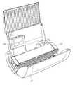
- the base 8is formed on the underside of the lower frame unit 6 and has a lower surface 13 that supports the printer unit 2 when the printer unit is positioned on a substantially horizontal surface, such as a surface of a desk in a home or office environment.
- One or more foot supports 14extend from the lower surface 13 to provide additional stability to the printer unit.
- the foot supports 14are made from a friction inducing material such as rubber, to increase the frictional contact between the printer unit and the support surface.
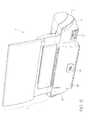
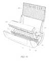
- a margin slider 42is adapted to be fitted over the working surface 35 of the tray portion 32 via an integral hook element 43 .
- a grooved recess 44is provided in the working surface 35 to receive a locating lug (not shown) of the slider 42 .
- the margin slider 42extends the height of the tray portion 32 and is provided with a wall portion 45 that extends out from the working surface 35 of the tray portion 32 to abut against a side edge of the print media 34 . This arrangement ensures that the print media 34 is properly aligned within the tray portion 32 to ensure controlled delivery of the sheets of media to the print engine 70 .
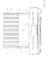
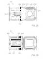
- FIG. 27shows an array of the nozzle arrangements 801 formed on a silicon substrate 8015 .
- Each of the nozzle arrangements 801are identical, however groups of nozzle arrangements 801 are arranged to be fed with different colored inks or fixative.
- the nozzle arrangementsare arranged in rows and are staggered with respect to each other, allowing closer spacing of ink dots during printing than would be possible with a single row of nozzles.
- Such an arrangementmakes it possible to provide the density of nozzles as described above.
- the multiple rowsalso allow for redundancy (if desired), thereby allowing for a predetermined failure rate per nozzle.
- the dot latches and the latches forming the various shift registersare fully static in this embodiment, and are CMOS-based.
- the design and construction of latchesis well known to those skilled in the art of integrated circuit engineering and design, and so will not be described in detail in this document.
Landscapes
- Accessory Devices And Overall Control Thereof (AREA)
Abstract
Description
| 7,152,972 | 7,543,808 | 7,621,620 | 7,669,961 | 7,331,663 | 7,360,861 |
| 7,328,973 | 7,427,121 | 7,407,262 | 7,303,252 | 7,249,822 | 7,537,309 |
| 7,311,382 | 7,360,860 | 7,364,257 | 7,390,075 | 7,350,896 | 7,429,096 |
| 7,384,135 | 7,331,660 | 7,416,287 | 7,488,052 | 7,322,684 | 7,322,685 |
| 7,311,381 | 7,270,405 | 7,303,268 | 7,470,007 | 7,399,072 | 7,393,076 |
| 7,681,967 | 7,588,301 | 7,249,833 | 7,524,016 | 7,490,927 | 7,331,661 |
| 7,524,043 | 7,300,140 | 7,357,492 | 7,357,493 | 7,566,106 | 7,380,902 |
| 7,284,816 | 7,284,845 | 7,255,430 | 7,390,080 | 7,328,984 | 7,350,913 |
| 7,322,671 | 7,380,910 | 7,431,424 | 7,470,006 | 7,585,054 | 7,347,534 |
| 7,377,635 | 7,686,446 | 11/014,730 | |||
| 7,364,256 | 7,258,417 | 7,293,853 | 7,328,968 | 7,270,395 | ||
| 7,461,916 | 7,510,264 | 7,334,864 | 7,255,419 | 7,284,819 | ||
| 7,229,148 | 7,258,416 | 7,273,263 | 7,270,393 | 6,984,017 | ||
| 7,347,526 | 7,465,015 | 7,364,255 | 7,357,476 | 11/003,614 | ||
| 7,284,820 | 7,341,328 | 7,246,875 | 7,322,669 | 6,623,101 | ||
| 6,406,129 | 6,505,916 | 6,457,809 | 6,550,895 | 6,457,812 | ||
| 7,152,962 | 6,428,133 | 7,204,941 | 7,282,164 | 7,465,342 | ||
| 7,278,727 | 7,417,141 | 7,452,989 | 7,367,665 | 7,138,391 | ||
| 7,153,956 | 7,423,145 | 7,456,277 | 7,550,585 | 7,122,076 | ||
| 7,148,345 | 7,416,280 | 7,252,366 | 7,488,051 | 7,360,865 | ||
| 7,628,468 | 7,334,874 | 7,393,083 | 7,475,965 | 7,578,582 | ||
| 7,591,539 | 10/922,887 | 7,472,984 | 10/922,874 | 7,234,795 | ||
| 7,401,884 | 7,328,975 | 7,293,855 | 7,410,250 | 7,401,900 | ||
| 7,527,357 | 7,410,243 | 7,360,871 | 7,708,372 | 6,746,105 | ||
| 7,156,508 | 7,159,972 | 7,083,271 | 7,165,834 | 7,080,894 | ||
| 7,201,469 | 7,090,336 | 7,156,489 | 7,413,283 | 7,438,385 | ||
| 7,083,257 | 7,258,422 | 7,255,423 | 7,219,980 | 7,591,533 | ||
| 7,416,274 | 7,367,649 | 7,118,192 | 7,618,121 | 7,322,672 | ||
| 7,077,505 | 7,198,354 | 7,077,504 | 7,614,724 | 7,198,355 | ||
| 7,401,894 | 7,322,676 | 7,152,959 | 7,213,906 | 7,178,901 | ||
| 7,222,938 | 7,108,353 | 7,104,629 | 7,246,886 | 7,128,400 | ||
| 7,108,355 | 6,991,322 | 7,287,836 | 7,118,197 | 7,575,298 | ||
| 7,364,269 | 7,077,493 | 6,962,402 | 7,686,429 | 7,147,308 | ||
| 7,524,034 | 7,118,198 | 7,168,790 | 7,172,270 | 7,229,155 | ||
| 6,830,318 | 7,195,342 | 7,175,261 | 7,465,035 | 7,108,356 | ||
| 7,118,202 | 7,510,269 | 7,134,744 | 7,510,270 | 7,134,743 | ||
| 7,182,439 | 7,210,768 | 7,465,036 | 7,134,745 | 7,156,484 | ||
| 7,118,201 | 7,111,926 | 7,431,433 | 7,721,948 | 7,079,712 | ||
| 6,825,945 | 7,330,974 | 6,813,039 | 6,987,506 | 7,038,797 | ||
| 6,980,318 | 6,816,274 | 7,102,772 | 7,350,236 | 6,681,045 | ||
| 6,728,000 | 7,173,722 | 7,088,459 | 7,707,082 | 7,068,382 | ||
| 7,062,651 | 6,789,194 | 6,789,191 | 6,644,642 | 6,502,614 | ||
| 6,622,999 | 6,669,385 | 6,549,935 | 6,987,573 | 6,727,996 | ||
| 6,591,884 | 6,439,706 | 6,760,119 | 7,295,332 | 7,064,851 | ||
| 6,826,547 | 6,290,349 | 6,428,155 | 6,785,016 | 6,831,682 | ||
| 6,741,871 | 6,927,871 | 6,980,306 | 6,965,439 | 6,840,606 | ||
| 7,036,918 | 6,977,746 | 6,970,264 | 7,068,389 | 7,093,991 | ||
| 7,190,491 | 7,511,847 | 7,663,780 | 10/962,412 | 7,177,054 | ||
| 7,364,282 | 10/965,733 | 10/965,933 | 10/974,742 | 7,538,793 | ||
| 6,982,798 | 6,870,966 | 6,822,639 | 6,737,591 | 7,055,739 | ||
| 7,233,320 | 6,830,196 | 6,832,717 | 6,957,768 | 7,170,499 | ||
| 7,106,888 | 7,123,239 | 10/727,162 | 7,377,608 | 7,399,043 | ||
| 7,121,639 | 7,165,824 | 7,152,942 | 10/727,157 | 7,181,572 | ||
| 7,096,137 | 7,302,592 | 7,278,034 | 7,188,282 | 7,592,829 | ||
| 10/727,180 | 10/727,179 | 10/727,192 | 10/727,274 | 7,707,621 | ||
| 7,523,111 | 7,573,301 | 7,660,998 | 10/754,536 | 10/754,938 | ||
| 10/727,160 | 7,369,270 | 6,795,215 | 7,070,098 | 7,154,638 | ||
| 6,805,419 | 6,859,289 | 6,977,751 | 6,398,332 | 6,394,573 | ||
| 6,622,923 | 6,747,760 | 6,921,144 | 10/884,881 | 7,092,112 | ||
| 7,192,106 | 7,374,266 | 7,427,117 | 7,448,707 | 7,281,330 | ||
| 10/854,503 | 7,328,956 | 10/854,509 | 7,188,928 | 7,093,989 | ||
| 7,377,609 | 7,600,843 | 10/854,498 | 10/854,511 | 7,390,071 | ||
| 10/854,525 | 10/854,526 | 7,549,715 | 7,252,353 | 7,607,757 | ||
| 7,267,417 | 10/854,505 | 7,517,036 | 7,275,805 | 7,314,261 | ||
| 7,281,777 | 7,290,852 | 7,484,831 | 10/854,523 | 10/854,527 | ||
| 7,549,718 | 10/854,520 | 7,631,190 | 7,557,941 | 10/854,499 | ||
| 10/854,501 | 7,266,661 | 7,243,193 | 10/854,518 | 10/934,628 | ||
| Name | Direction | Description |
| D | Input | Input dot pattern to shift register bit |
| Q | Output | Output dot pattern from shift register bit |
| SrClk | Input | Shift register clock in - d is captured on rising edge |
| of this clock | ||
| LsyncL | Input | Fire enable - needs to be asserted for nozzle to fire |
| Pr | Input | Profile - needs to be asserted for nozzle to fire |
Claims (7)
Priority Applications (1)
| Application Number | Priority Date | Filing Date | Title |
|---|---|---|---|
| US12/786,356US8100502B2 (en) | 2004-01-21 | 2010-05-24 | Printer cartridge incorporating printhead integrated circuit |
Applications Claiming Priority (4)
| Application Number | Priority Date | Filing Date | Title |
|---|---|---|---|
| US10/760,254US7448734B2 (en) | 2004-01-21 | 2004-01-21 | Inkjet printer cartridge with pagewidth printhead |
| US11/014,722US7306320B2 (en) | 2003-11-12 | 2004-12-20 | High speed digital printer unit |
| US11/934,781US7731327B2 (en) | 2004-01-21 | 2007-11-04 | Desktop printer with cartridge incorporating printhead integrated circuit |
| US12/786,356US8100502B2 (en) | 2004-01-21 | 2010-05-24 | Printer cartridge incorporating printhead integrated circuit |
Related Parent Applications (1)
| Application Number | Title | Priority Date | Filing Date |
|---|---|---|---|
| US11/934,781ContinuationUS7731327B2 (en) | 2004-01-21 | 2007-11-04 | Desktop printer with cartridge incorporating printhead integrated circuit |
Publications (2)
| Publication Number | Publication Date |
|---|---|
| US20100231642A1 US20100231642A1 (en) | 2010-09-16 |
| US8100502B2true US8100502B2 (en) | 2012-01-24 |
Family
ID=46329777
Family Applications (2)
| Application Number | Title | Priority Date | Filing Date |
|---|---|---|---|
| US11/934,781Expired - Fee RelatedUS7731327B2 (en) | 2004-01-21 | 2007-11-04 | Desktop printer with cartridge incorporating printhead integrated circuit |
| US12/786,356Expired - Fee RelatedUS8100502B2 (en) | 2004-01-21 | 2010-05-24 | Printer cartridge incorporating printhead integrated circuit |
Family Applications Before (1)
| Application Number | Title | Priority Date | Filing Date |
|---|---|---|---|
| US11/934,781Expired - Fee RelatedUS7731327B2 (en) | 2004-01-21 | 2007-11-04 | Desktop printer with cartridge incorporating printhead integrated circuit |
Country Status (1)
| Country | Link |
|---|---|
| US (2) | US7731327B2 (en) |
Families Citing this family (15)
| Publication number | Priority date | Publication date | Assignee | Title |
|---|---|---|---|---|
| US7097291B2 (en)* | 2004-01-21 | 2006-08-29 | Silverbrook Research Pty Ltd | Inkjet printer cartridge with ink refill port having multiple ink couplings |
| US7441865B2 (en) | 2004-01-21 | 2008-10-28 | Silverbrook Research Pty Ltd | Printhead chip having longitudinal ink supply channels |
| US7121655B2 (en)* | 2004-01-21 | 2006-10-17 | Silverbrook Research Pty Ltd | Inkjet printer cartridge refill dispenser |
| US7731327B2 (en)* | 2004-01-21 | 2010-06-08 | Silverbrook Research Pty Ltd | Desktop printer with cartridge incorporating printhead integrated circuit |
| US7232208B2 (en)* | 2004-01-21 | 2007-06-19 | Silverbrook Research Pty Ltd | Inkjet printer cartridge refill dispenser with plunge action |
| US7425050B2 (en)* | 2004-01-21 | 2008-09-16 | Silverbrook Research Pty Ltd | Method for facilitating maintenance of an inkjet printer having a pagewidth printhead |
| US7448734B2 (en)* | 2004-01-21 | 2008-11-11 | Silverbrook Research Pty Ltd | Inkjet printer cartridge with pagewidth printhead |
| US7303255B2 (en)* | 2004-01-21 | 2007-12-04 | Silverbrook Research Pty Ltd | Inkjet printer cartridge with a compressed air port |
| US8607281B2 (en) | 2006-09-07 | 2013-12-10 | Porto Vinci Ltd. Limited Liability Company | Control of data presentation in multiple zones using a wireless home entertainment hub |
| US9233301B2 (en) | 2006-09-07 | 2016-01-12 | Rateze Remote Mgmt Llc | Control of data presentation from multiple sources using a wireless home entertainment hub |
| US9319741B2 (en) | 2006-09-07 | 2016-04-19 | Rateze Remote Mgmt Llc | Finding devices in an entertainment system |
| US8005236B2 (en) | 2006-09-07 | 2011-08-23 | Porto Vinci Ltd. Limited Liability Company | Control of data presentation using a wireless home entertainment hub |
| US8935733B2 (en) | 2006-09-07 | 2015-01-13 | Porto Vinci Ltd. Limited Liability Company | Data presentation using a wireless home entertainment hub |
| US9386269B2 (en) | 2006-09-07 | 2016-07-05 | Rateze Remote Mgmt Llc | Presentation of data on multiple display devices using a wireless hub |
| CA3167149A1 (en)* | 2020-01-08 | 2021-07-15 | Brady Worldwide, Inc. | Specialized inksets and alternative fluids and related systems |
Citations (146)
| Publication number | Priority date | Publication date | Assignee | Title |
|---|---|---|---|---|
| US1880354A (en) | 1931-07-30 | 1932-10-04 | Herman C Mueller | Fluid gun |
| US3868698A (en) | 1973-10-24 | 1975-02-25 | Mead Corp | Stimulation control apparatus for an ink jet recorder |
| JPS57159658A (en) | 1981-03-27 | 1982-10-01 | Fujitsu Ltd | Ink jet recording head |
| US4447820A (en) | 1981-06-08 | 1984-05-08 | Canon Kabushiki Kaisha | Ink supplying mechanism |
| US4580148A (en) | 1985-02-19 | 1986-04-01 | Xerox Corporation | Thermal ink jet printer with droplet ejection by bubble collapse |
| US4594597A (en) | 1985-08-13 | 1986-06-10 | Sanders Associates, Inc. | Thermal printer |
| US4628332A (en) | 1984-01-30 | 1986-12-09 | Canon Kabushiki Kaisha | Ink printhead with holder mount |
| US4771295A (en) | 1986-07-01 | 1988-09-13 | Hewlett-Packard Company | Thermal ink jet pen body construction having improved ink storage and feed capability |
| US4985710A (en) | 1989-11-29 | 1991-01-15 | Xerox Corporation | Buttable subunits for pagewidth "Roofshooter" printheads |
| US5049898A (en) | 1989-03-20 | 1991-09-17 | Hewlett-Packard Company | Printhead having memory element |
| US5051761A (en) | 1990-05-09 | 1991-09-24 | Xerox Corporation | Ink jet printer having a paper handling and maintenance station assembly |
| US5160945A (en) | 1991-05-10 | 1992-11-03 | Xerox Corporation | Pagewidth thermal ink jet printhead |
| US5182581A (en) | 1988-07-26 | 1993-01-26 | Canon Kabushiki Kaisha | Ink jet recording unit having an ink tank section containing porous material and a recording head section |
| US5221397A (en) | 1992-11-02 | 1993-06-22 | Xerox Corporation | Fabrication of reading or writing bar arrays assembled from subunits |
| US5376957A (en) | 1992-06-08 | 1994-12-27 | Signtech Usa, Ltd. | Ink jet printer |
| US5404158A (en) | 1992-11-12 | 1995-04-04 | Xerox Corporation | Ink jet printer maintenance system |
| US5409134A (en) | 1990-01-12 | 1995-04-25 | Hewlett-Packard Corporation | Pressure-sensitive accumulator for ink-jet pens |
| US5486855A (en) | 1990-12-27 | 1996-01-23 | Xerox Corporation | Apparatus for supplying ink to an ink jet printer |
| US5512924A (en) | 1988-12-28 | 1996-04-30 | Canon Kabushiki Kaisha | Jet apparatus having an ink jet head and temperature controller for that head |
| US5530463A (en)* | 1994-08-25 | 1996-06-25 | Xerox Corporation | Integral seal for ink jet printheads |
| US5577613A (en) | 1995-09-06 | 1996-11-26 | Hewlett-Packard Company | Integrated carry handle and accessory interlock system |
| US5682186A (en) | 1994-03-10 | 1997-10-28 | Hewlett-Packard Company | Protective capping apparatus for an ink-jet pen |
| US5717444A (en)* | 1990-04-11 | 1998-02-10 | Canon Kabushiki Kaisha | Suction recovery device and ink jet recording apparatus using the device |
| US5812156A (en) | 1997-01-21 | 1998-09-22 | Hewlett-Packard Company | Apparatus controlled by data from consumable parts with incorporated memory devices |
| US5825378A (en) | 1993-04-30 | 1998-10-20 | Hewlett-Packard Company | Calibration of media advancement to avoid banding in a swath printer |
| US5852459A (en) | 1994-10-31 | 1998-12-22 | Hewlett-Packard Company | Printer using print cartridge with internal pressure regulator |
| US5877788A (en) | 1995-05-09 | 1999-03-02 | Moore Business Forms, Inc. | Cleaning fluid apparatus and method for continuous printing ink-jet nozzle |
| US5923350A (en) | 1993-09-03 | 1999-07-13 | Canon Kabushiki Kaisha | Recording apparatus with improved head installation mechanism |
| EP0940259A2 (en) | 1998-03-04 | 1999-09-08 | Hewlett-Packard Company | Electrical refurbishment for ink delivery system |
| US5963239A (en) | 1996-03-14 | 1999-10-05 | Seiko Epson Corporation | Ink jet recording apparatus and ink supply member therefor |
| US5982969A (en) | 1997-04-24 | 1999-11-09 | Bridgestone Corporation | Optical transmission tube, making method, and linear illuminant system |
| US6017117A (en) | 1995-10-31 | 2000-01-25 | Hewlett-Packard Company | Printhead with pump driven ink circulation |
| US6019463A (en) | 1994-05-20 | 2000-02-01 | Citizen Watch Co., Ltd | Ink cartridge |
| US6022102A (en) | 1996-04-25 | 2000-02-08 | Canon Kabushiki Kaisha | Method for refilling liquid into a liquid reservoir container, a liquid jet recording apparatus using such method, a liquid refilling container, a liquid reservoir container, and a head cartridge |
| US6045214A (en) | 1997-03-28 | 2000-04-04 | Lexmark International, Inc. | Ink jet printer nozzle plate having improved flow feature design and method of making nozzle plates |
| US6079819A (en) | 1998-01-08 | 2000-06-27 | Xerox Corporation | Ink jet printhead having a low cross talk ink channel structure |
| US6084622A (en) | 1993-04-28 | 2000-07-04 | Canon Kabushiki Kaisha | Frame structure and an image forming apparatus using such a frame structure |
| US6116716A (en) | 1996-07-12 | 2000-09-12 | Canon Kabushiki Kaisha | Method for standardizing an ink jet recording head and an ink jet recording head for attaining such standardization, ink jet recording method, and information processing apparatus, and host apparatus |
| US6120138A (en) | 1997-05-12 | 2000-09-19 | Hana Company Limited | Refill assembly for printer ink cartridges |
| US6145973A (en) | 1999-09-14 | 2000-11-14 | Wisertek International Corp. | Ink-jet cartridge |
| US6151041A (en) | 1998-10-19 | 2000-11-21 | Lexmark International, Inc. | Less restrictive print head cartridge installation in an ink jet printer |
| US6155664A (en) | 1998-06-19 | 2000-12-05 | Lexmark International, Inc. | Off-carrier inkjet print supply with memory |
| US6155678A (en) | 1999-10-06 | 2000-12-05 | Lexmark International, Inc. | Replaceable ink cartridge for ink jet pen |
| WO2001002172A1 (en) | 1999-06-30 | 2001-01-11 | Silverbrook Research Pty Ltd | Printhead support structure and assembly |
| US6199977B1 (en) | 2000-04-13 | 2001-03-13 | Lexmark International, Inc. | Cartridge body for ink jet printer |
| US6206511B1 (en) | 1998-06-19 | 2001-03-27 | Lexmark International, Inc. | Multiple-cartridge off-board ink supplies for color ink jet printers |
| JP2001096847A (en) | 1999-10-01 | 2001-04-10 | Canon Inc | Printing equipment |
| JP2001106344A (en) | 1999-10-05 | 2001-04-17 | Oki Data Corp | Printer |
| US6229114B1 (en) | 1999-09-30 | 2001-05-08 | Xerox Corporation | Precision laser cutting of adhesive members |
| US6238044B1 (en) | 2000-06-30 | 2001-05-29 | Silverbrook Research Pty Ltd | Print cartridge |
| US6241347B1 (en) | 1997-03-03 | 2001-06-05 | Hewlett-Packard Company | Inkjet printing with replaceable set of ink-related components (printhead/service module/ink supply) for each color of ink |
| WO2001039981A1 (en) | 1999-12-01 | 2001-06-07 | Sony Corporation | Method of driving print head in inkjet printer, and inkjet printer |
| US6247803B1 (en) | 1983-10-13 | 2001-06-19 | Seiko Epson Corporation | Ink jet recording apparatus and method for replenishing ink in the tank cartridge |
| US6250738B1 (en) | 1997-10-28 | 2001-06-26 | Hewlett-Packard Company | Inkjet printing apparatus with ink manifold |
| US6257713B1 (en) | 1996-03-29 | 2001-07-10 | Samsung Electronics Co., Ltd. | Device for refilling color inks in an ink-jet printer |
| US20010007463A1 (en) | 1999-12-06 | 2001-07-12 | Hiroki Hayashi | Surface reformed fiber body, liquid container using fiber absorber, and method of producing fiber absorber for use in liquid ejection |
| US20010009432A1 (en) | 1999-10-29 | 2001-07-26 | David Olsen | Ink reservoir for an inkjet printer |
| JP2001205820A (en) | 2000-01-05 | 2001-07-31 | Hewlett Packard Co <Hp> | Ink-jet pen with lid consisting of two parts and filling method |
| US20010010530A1 (en) | 1998-01-23 | 2001-08-02 | Haines Paul Mark | Diaphragm pump having an integral pressure plate |
| US6270182B1 (en) | 1997-07-15 | 2001-08-07 | Silverbrook Research Pty Ltd | Inkjet print head recapping mechanism |
| US6270177B1 (en) | 1998-11-09 | 2001-08-07 | Silverbrook Research Pty Ltd | Printer unit for PC disk drive bay |
| US6276787B1 (en) | 1997-09-26 | 2001-08-21 | Brother Kogyo Kabushiki Kaisha | Ink supplying device |
| US6281912B1 (en) | 2000-05-23 | 2001-08-28 | Silverbrook Research Pty Ltd | Air supply arrangement for a printer |
| WO2001064441A1 (en) | 2000-03-02 | 2001-09-07 | Silverbrook Research Pty Ltd | Manually aligned printhead modules |
| US6290349B1 (en) | 1999-05-25 | 2001-09-18 | Silverbrook Research Pty Ltd | Printer consumable cartridge |
| US6293658B1 (en) | 1997-07-15 | 2001-09-25 | Silverbrook Research Pty Ltd | Printhead ink supply system |
| US6302022B1 (en) | 2000-10-20 | 2001-10-16 | Shiny Shih | Ink refillable stamp |
| US6318920B1 (en) | 2000-05-23 | 2001-11-20 | Silverbrook Research Pty Ltd | Rotating platen member |
| US6322206B1 (en) | 1997-10-28 | 2001-11-27 | Hewlett-Packard Company | Multilayered platform for multiple printhead dies |
| US20010048453A1 (en) | 2000-06-01 | 2001-12-06 | Lattuca Michael D. | Ink cartridge body and carrier assembly |
| US6338552B1 (en) | 1995-11-08 | 2002-01-15 | Canon Kabushiki Kaisha | Ink refilling method and apparatus, ink container refilled therewith and ink jet apparatus comprising ink refilling apparatus |
| JP2002029045A (en) | 2000-07-14 | 2002-01-29 | Sony Corp | Apparatus and method for managing cartridge, and computer readable program storage medium storing program having cartridge managing function recorded therein |
| US6341853B1 (en) | 1992-12-23 | 2002-01-29 | Hewlett-Packard Company | Continuous refill of spring bag reservoir in an ink-jet swath printer/plotter |
| US20020018104A1 (en) | 2000-05-23 | 2002-02-14 | Kia Silverbrook | Ink supply arrangement for a printer |
| US6347864B1 (en) | 2000-06-30 | 2002-02-19 | Silverbrook Research Pty Ltd | Print engine including an air pump |
| JP2002060117A (en) | 2000-08-21 | 2002-02-26 | Fuji Photo Film Co Ltd | Wall-mounted printer |
| US20020030712A1 (en) | 1997-07-12 | 2002-03-14 | Kia Silverbrook | Printing cartridge with an integrated circuit device |
| US20020044182A1 (en) | 2000-01-08 | 2002-04-18 | I-Chung Hou | Ink reservoir with a pressure adjusting device |
| US6382769B1 (en) | 1997-07-15 | 2002-05-07 | Silverbrook Research Pty Ltd | Method of tab alignment in an integrated circuit type device |
| JP2002127426A (en) | 2000-10-20 | 2002-05-08 | Sony Corp | Printer |
| US6386535B1 (en) | 2000-09-15 | 2002-05-14 | Silverbrook Research Pty Ltd | Loading mechanism for a modular commercial printer |
| US20020056962A1 (en) | 2000-11-13 | 2002-05-16 | Brother Kogyo Kabushiki Kaisha | Image forming apparatus and recording medium feeding apparatus for the same |
| US6390615B1 (en) | 2000-06-19 | 2002-05-21 | Xerox Corporation | Ink tank with securing means and seal |
| US6397035B2 (en) | 1998-10-16 | 2002-05-28 | Canon Kabushiki Kaisha | Image forming apparatus with control of conveying speeds |
| US20020093570A1 (en) | 2001-01-17 | 2002-07-18 | Kia Silverbrook | Personal digital assistant with internal printer |
| US20020109760A1 (en) | 2000-10-20 | 2002-08-15 | Hisashi Miyazawa | Ink cartridge for ink jet recording device |
| US6439908B1 (en)* | 1999-12-09 | 2002-08-27 | Silverbrook Research Pty Ltd | Power supply for a four color modular printhead |
| US6439683B1 (en) | 1998-03-11 | 2002-08-27 | Canon Kabushiki Kaisha | Image processing method and apparatus and recording apparatus |
| US6443555B1 (en) | 1999-03-16 | 2002-09-03 | Silverbrook Research Pty Ltd | Pagewidth wide format printer |
| US20020126188A1 (en) | 2001-03-09 | 2002-09-12 | Otis David R. | Inkjet printing system using filter fluid interconnects for pigmented inks |
| US6457810B1 (en) | 2000-10-20 | 2002-10-01 | Silverbrook Research Pty Ltd. | Method of assembly of six color inkjet modular printhead |
| US20020154184A1 (en) | 1997-07-15 | 2002-10-24 | Kia Silverbrook | High volume pagewidth printing |
| US6474796B1 (en) | 1996-12-05 | 2002-11-05 | Canon Kabushiki Kaisha | Method for filling a liquid into a liquid container, a filling unit for executing the filling method, a liquid container manufactured according to the filling method and a liquid ejection apparatus |
| US20020163566A1 (en) | 2001-05-03 | 2002-11-07 | Samsung Electronics Co., Ltd. | Apparatus to remove ink cartridge of ink-jet printer |
| US20020191057A1 (en) | 2000-10-06 | 2002-12-19 | Jones Bruce S | Pressurized ink filling method for dual compartment ink-jet cartridge used in ink-jet printer |
| US20030007045A1 (en) | 2001-06-18 | 2003-01-09 | Masahito Yoshida | Ink container, inkjet printing apparatus, and ink supplying method |
| US20030020789A1 (en) | 2001-07-24 | 2003-01-30 | Nanodynamics Inc. | Ink cartridge with negative-pressure regulating mechanism |
| US20030025773A1 (en) | 2001-08-01 | 2003-02-06 | Yutaka Koizumi | Liquid supplying device and liquid discharge recording apparatus |
| JP2003039708A (en) | 2000-05-29 | 2003-02-13 | Seiko Epson Corp | Cartridge filling device |
| JP2003054003A (en) | 1998-05-18 | 2003-02-26 | Seiko Epson Corp | ink cartridge |
| JP2003080772A (en) | 2001-09-13 | 2003-03-19 | Ricoh Co Ltd | Color image processing apparatus and image forming apparatus |
| US20030053840A1 (en) | 1999-10-25 | 2003-03-20 | Paul Lapstun | Electronically controllable pen device |
| US20030063168A1 (en) | 1994-09-16 | 2003-04-03 | Takao Kobayashi | Ink cartridge for ink jet printer and method of charging ink into said cartridge |
| US20030067520A1 (en) | 2001-10-05 | 2003-04-10 | Ryoji Inoue | Liquid container, liquid supplying apparatus, and recording apparatus |
| US20030076391A1 (en) | 2001-10-24 | 2003-04-24 | Wilson John F. | Supply adaptor for an on-axis printer |
| US6554398B2 (en) | 2001-03-08 | 2003-04-29 | Agfa-Gevaert | Ink-jet printer equipped for aligning the printheads |
| US6557976B2 (en) | 2001-02-14 | 2003-05-06 | Hewlett-Packard Development Company, L.P. | Electrical circuit for wide-array inkjet printhead assembly |
| WO2003068517A1 (en) | 2002-02-13 | 2003-08-21 | Silverbrook Research Pty. Ltd. | Speedstick plugin and reprogrammable modules, controllers and components |
| US20030160848A1 (en) | 2002-02-22 | 2003-08-28 | Canon Kabushiki Kaisha | Liquid container, ink jet cartridge and ink jet printing apparatus |
| US6631967B1 (en) | 1998-11-26 | 2003-10-14 | Seiko Epson Corporation | Printer and ink cartridge attached thereto |
| US6637858B2 (en) | 2001-10-30 | 2003-10-28 | Hewlett-Packard Development Company, L.P. | Printing mechanism hinged printbar assembly |
| US6637871B1 (en) | 1999-07-14 | 2003-10-28 | Videojet Technologies, Inc. | Droplet generator for a continuous stream ink jet print head |
| US6652082B2 (en) | 1998-10-16 | 2003-11-25 | Silverbrook Research Pty Ltd | Printhead assembly for an ink jet printer |
| US6672706B2 (en) | 1997-07-15 | 2004-01-06 | Silverbrook Research Pty Ltd | Wide format pagewidth inkjet printer |
| US20040021751A1 (en) | 2002-01-30 | 2004-02-05 | Charlie Steinmetz | Printing-fluid container |
| US20040036749A1 (en) | 2002-08-21 | 2004-02-26 | Eastman Kodak Company | Ink cartridge having ink supply bag filled to less than capacity and folded in cartridge housing |
| US20040061765A1 (en) | 2002-09-30 | 2004-04-01 | Shoichi Kan | Image forming apparatus |
| US6749294B2 (en) | 2002-10-10 | 2004-06-15 | Hewlett-Packard Development Company, L.P. | Keying methods and apparatus for inkjet print cartridges and inkjet printers |
| US6761114B2 (en) | 2000-05-04 | 2004-07-13 | Trodat Gmbh | Self-inking stamp |
| US20040135853A1 (en) | 2002-11-20 | 2004-07-15 | Canon Kabushiki Kaisha | Liquid reservoir apparatus |
| US6793319B2 (en) | 2000-07-25 | 2004-09-21 | Sony Corporation | Printer and printer head |
| US20040183871A1 (en) | 2002-01-30 | 2004-09-23 | Childers Winthrop D. | Method and device for filling a printing-fluid container |
| US20040196341A1 (en) | 2003-04-04 | 2004-10-07 | Canon Kabushiki Kaisha | Liquid container, liquid using device, printing apparatus, and method of manufacturing liquid container |
| US20040212647A1 (en) | 2000-01-20 | 2004-10-28 | Yuji Yakura | Method for driving recording head, recording head, and ink jet printer |
| US6851799B2 (en) | 2001-08-16 | 2005-02-08 | Eastman Kodak Company | Ink cartridge with memory chip and method of assembling |
| US20050035998A1 (en) | 2001-05-11 | 2005-02-17 | Makoto Ando | Ink jet print head, inkjet printer including the inkjet print head, and method of manufacturing inkjet print head |
| US20050052507A1 (en) | 2003-09-10 | 2005-03-10 | Dewey Jason S. | Apparatus for securing print cartridge in ink jet printer |
| US20050052508A1 (en) | 2003-09-10 | 2005-03-10 | Wirth Steven J. | Ink jet print system including print cartridge |
| US20050157102A1 (en) | 2004-01-21 | 2005-07-21 | Silverbrook Research Pty Ltd | Inkjet printer cartridge refill dispenser |
| US6988840B2 (en) | 2000-05-23 | 2006-01-24 | Silverbrook Research Pty Ltd | Printhead chassis assembly |
| US20060139420A1 (en) | 2002-12-06 | 2006-06-29 | Masakazu Muranaka | Ink cartridge, housing therefor, ink bag, ink-jet recording apparatus, ink container, and image-forming apparatus |
| US7152972B2 (en) | 2004-01-21 | 2006-12-26 | Silverbrook Research Pty Ltd | Combination printer and image reader in L-shaped configuration |
| US7232208B2 (en) | 2004-01-21 | 2007-06-19 | Silverbrook Research Pty Ltd | Inkjet printer cartridge refill dispenser with plunge action |
| US7258432B2 (en) | 2004-01-21 | 2007-08-21 | Silverbrook Research Pty Ltd | Inkjet printer cartridge with controlled refill |
| US7306325B2 (en) | 2004-01-21 | 2007-12-11 | Silverbrook Research Pty Ltd | Inkjet printer having ink distribution to fixedly attached printhead ICS |
| US7306309B2 (en) | 2003-02-27 | 2007-12-11 | Sony Corporation | Liquid discharge apparatus and method for discharging liquid |
| US7306320B2 (en)* | 2003-11-12 | 2007-12-11 | Silverbrook Research Pty Ltd | High speed digital printer unit |
| US7441865B2 (en) | 2004-01-21 | 2008-10-28 | Silverbrook Research Pty Ltd | Printhead chip having longitudinal ink supply channels |
| US7458665B2 (en) | 2001-11-06 | 2008-12-02 | Gemplus | Machine fluid supply assembly comprising keying means |
| US7469989B2 (en) | 2004-01-21 | 2008-12-30 | Silverbrook Research Pty Ltd | Printhead chip having longitudinal ink supply channels interrupted by transverse bridges |
| US7517050B2 (en) | 2004-01-21 | 2009-04-14 | Silverbrook Research Pty Ltd | Printer cradle having shock absorption for removable print cartridge |
| US7530662B2 (en) | 2004-01-21 | 2009-05-12 | Silverbrook Research Pty Ltd | Driven mechanism with an air compressor for a printer cradle unit |
| US7611234B2 (en) | 2004-01-21 | 2009-11-03 | Silverbrook Research Pty Ltd | Ink refill cartridge with an internal spring assembly for a printer |
| US7645025B2 (en) | 2004-01-21 | 2010-01-12 | Silverbrook Research Pty Ltd | Inkjet printer cartridge with two printhead integrated circuits |
| US7690747B2 (en) | 2004-01-21 | 2010-04-06 | Silverbrook Research Pty Ltd | Inkjet printer assembly with a controller for detecting a performance characteristic of a printer cartridge |
| US7731327B2 (en)* | 2004-01-21 | 2010-06-08 | Silverbrook Research Pty Ltd | Desktop printer with cartridge incorporating printhead integrated circuit |
Family Cites Families (9)
| Publication number | Priority date | Publication date | Assignee | Title |
|---|---|---|---|---|
| US3019463A (en)* | 1959-09-02 | 1962-02-06 | Samuel L Mitchell | Power hair brush |
| JPH0299358A (en) | 1988-10-07 | 1990-04-11 | Canon Inc | recording device |
| JP2752495B2 (en) | 1990-02-13 | 1998-05-18 | キヤノン株式会社 | Ink jet recording device |
| JPH0918642A (en) | 1995-07-03 | 1997-01-17 | Canon Inc | Image information processing device |
| FR2768078B1 (en) | 1997-09-10 | 1999-11-26 | Neopost Ind | MAINTENANCE STATION FOR INK JET PRINTING MACHINE |
| DE69932652T2 (en) | 1998-12-16 | 2007-08-09 | Silverbrook Research Pty. Ltd., Balmain | Control system for printing on both sides of a print medium |
| JP3763726B2 (en) | 1999-07-14 | 2006-04-05 | キヤノンファインテック株式会社 | Inkjet recording device |
| JP2001212984A (en) | 2000-02-03 | 2001-08-07 | Canon Inc | Ink jet recording device |
| JP2003341023A (en) | 2002-05-24 | 2003-12-03 | Seiko Epson Corp | Printing apparatus, printing method, computer program, and computer system |
- 2007
- 2007-11-04USUS11/934,781patent/US7731327B2/ennot_activeExpired - Fee Related
- 2010
- 2010-05-24USUS12/786,356patent/US8100502B2/ennot_activeExpired - Fee Related
Patent Citations (184)
| Publication number | Priority date | Publication date | Assignee | Title |
|---|---|---|---|---|
| US1880354A (en) | 1931-07-30 | 1932-10-04 | Herman C Mueller | Fluid gun |
| US3868698A (en) | 1973-10-24 | 1975-02-25 | Mead Corp | Stimulation control apparatus for an ink jet recorder |
| JPS57159658A (en) | 1981-03-27 | 1982-10-01 | Fujitsu Ltd | Ink jet recording head |
| US4447820A (en) | 1981-06-08 | 1984-05-08 | Canon Kabushiki Kaisha | Ink supplying mechanism |
| US6247803B1 (en) | 1983-10-13 | 2001-06-19 | Seiko Epson Corporation | Ink jet recording apparatus and method for replenishing ink in the tank cartridge |
| US4628332A (en) | 1984-01-30 | 1986-12-09 | Canon Kabushiki Kaisha | Ink printhead with holder mount |
| US4580148A (en) | 1985-02-19 | 1986-04-01 | Xerox Corporation | Thermal ink jet printer with droplet ejection by bubble collapse |
| US4594597A (en) | 1985-08-13 | 1986-06-10 | Sanders Associates, Inc. | Thermal printer |
| US4771295A (en) | 1986-07-01 | 1988-09-13 | Hewlett-Packard Company | Thermal ink jet pen body construction having improved ink storage and feed capability |
| US4771295B1 (en) | 1986-07-01 | 1995-08-01 | Hewlett Packard Co | Thermal ink jet pen body construction having improved ink storage and feed capability |
| US5182581A (en) | 1988-07-26 | 1993-01-26 | Canon Kabushiki Kaisha | Ink jet recording unit having an ink tank section containing porous material and a recording head section |
| US5512924A (en) | 1988-12-28 | 1996-04-30 | Canon Kabushiki Kaisha | Jet apparatus having an ink jet head and temperature controller for that head |
| US5049898A (en) | 1989-03-20 | 1991-09-17 | Hewlett-Packard Company | Printhead having memory element |
| US4985710A (en) | 1989-11-29 | 1991-01-15 | Xerox Corporation | Buttable subunits for pagewidth "Roofshooter" printheads |
| US5409134A (en) | 1990-01-12 | 1995-04-25 | Hewlett-Packard Corporation | Pressure-sensitive accumulator for ink-jet pens |
| US5717444A (en)* | 1990-04-11 | 1998-02-10 | Canon Kabushiki Kaisha | Suction recovery device and ink jet recording apparatus using the device |
| US5051761A (en) | 1990-05-09 | 1991-09-24 | Xerox Corporation | Ink jet printer having a paper handling and maintenance station assembly |
| US5486855A (en) | 1990-12-27 | 1996-01-23 | Xerox Corporation | Apparatus for supplying ink to an ink jet printer |
| US5160945A (en) | 1991-05-10 | 1992-11-03 | Xerox Corporation | Pagewidth thermal ink jet printhead |
| US5376957A (en) | 1992-06-08 | 1994-12-27 | Signtech Usa, Ltd. | Ink jet printer |
| US5221397A (en) | 1992-11-02 | 1993-06-22 | Xerox Corporation | Fabrication of reading or writing bar arrays assembled from subunits |
| US5404158A (en) | 1992-11-12 | 1995-04-04 | Xerox Corporation | Ink jet printer maintenance system |
| US6341853B1 (en) | 1992-12-23 | 2002-01-29 | Hewlett-Packard Company | Continuous refill of spring bag reservoir in an ink-jet swath printer/plotter |
| US6084622A (en) | 1993-04-28 | 2000-07-04 | Canon Kabushiki Kaisha | Frame structure and an image forming apparatus using such a frame structure |
| US5825378A (en) | 1993-04-30 | 1998-10-20 | Hewlett-Packard Company | Calibration of media advancement to avoid banding in a swath printer |
| US5923350A (en) | 1993-09-03 | 1999-07-13 | Canon Kabushiki Kaisha | Recording apparatus with improved head installation mechanism |
| US5682186A (en) | 1994-03-10 | 1997-10-28 | Hewlett-Packard Company | Protective capping apparatus for an ink-jet pen |
| US6019463A (en) | 1994-05-20 | 2000-02-01 | Citizen Watch Co., Ltd | Ink cartridge |
| US5530463A (en)* | 1994-08-25 | 1996-06-25 | Xerox Corporation | Integral seal for ink jet printheads |
| US20030063168A1 (en) | 1994-09-16 | 2003-04-03 | Takao Kobayashi | Ink cartridge for ink jet printer and method of charging ink into said cartridge |
| US5852459A (en) | 1994-10-31 | 1998-12-22 | Hewlett-Packard Company | Printer using print cartridge with internal pressure regulator |
| US5877788A (en) | 1995-05-09 | 1999-03-02 | Moore Business Forms, Inc. | Cleaning fluid apparatus and method for continuous printing ink-jet nozzle |
| US5577613A (en) | 1995-09-06 | 1996-11-26 | Hewlett-Packard Company | Integrated carry handle and accessory interlock system |
| US6017117A (en) | 1995-10-31 | 2000-01-25 | Hewlett-Packard Company | Printhead with pump driven ink circulation |
| US6338552B1 (en) | 1995-11-08 | 2002-01-15 | Canon Kabushiki Kaisha | Ink refilling method and apparatus, ink container refilled therewith and ink jet apparatus comprising ink refilling apparatus |
| US5963239A (en) | 1996-03-14 | 1999-10-05 | Seiko Epson Corporation | Ink jet recording apparatus and ink supply member therefor |
| US6257713B1 (en) | 1996-03-29 | 2001-07-10 | Samsung Electronics Co., Ltd. | Device for refilling color inks in an ink-jet printer |
| US6022102A (en) | 1996-04-25 | 2000-02-08 | Canon Kabushiki Kaisha | Method for refilling liquid into a liquid reservoir container, a liquid jet recording apparatus using such method, a liquid refilling container, a liquid reservoir container, and a head cartridge |
| US6116716A (en) | 1996-07-12 | 2000-09-12 | Canon Kabushiki Kaisha | Method for standardizing an ink jet recording head and an ink jet recording head for attaining such standardization, ink jet recording method, and information processing apparatus, and host apparatus |
| US6474796B1 (en) | 1996-12-05 | 2002-11-05 | Canon Kabushiki Kaisha | Method for filling a liquid into a liquid container, a filling unit for executing the filling method, a liquid container manufactured according to the filling method and a liquid ejection apparatus |
| US5812156A (en) | 1997-01-21 | 1998-09-22 | Hewlett-Packard Company | Apparatus controlled by data from consumable parts with incorporated memory devices |
| US6241347B1 (en) | 1997-03-03 | 2001-06-05 | Hewlett-Packard Company | Inkjet printing with replaceable set of ink-related components (printhead/service module/ink supply) for each color of ink |
| US6045214A (en) | 1997-03-28 | 2000-04-04 | Lexmark International, Inc. | Ink jet printer nozzle plate having improved flow feature design and method of making nozzle plates |
| US5982969A (en) | 1997-04-24 | 1999-11-09 | Bridgestone Corporation | Optical transmission tube, making method, and linear illuminant system |
| US6120138A (en) | 1997-05-12 | 2000-09-19 | Hana Company Limited | Refill assembly for printer ink cartridges |
| US20020030712A1 (en) | 1997-07-12 | 2002-03-14 | Kia Silverbrook | Printing cartridge with an integrated circuit device |
| US20020154184A1 (en) | 1997-07-15 | 2002-10-24 | Kia Silverbrook | High volume pagewidth printing |
| US6382769B1 (en) | 1997-07-15 | 2002-05-07 | Silverbrook Research Pty Ltd | Method of tab alignment in an integrated circuit type device |
| US6672706B2 (en) | 1997-07-15 | 2004-01-06 | Silverbrook Research Pty Ltd | Wide format pagewidth inkjet printer |
| US6293658B1 (en) | 1997-07-15 | 2001-09-25 | Silverbrook Research Pty Ltd | Printhead ink supply system |
| US6270182B1 (en) | 1997-07-15 | 2001-08-07 | Silverbrook Research Pty Ltd | Inkjet print head recapping mechanism |
| US6679584B2 (en) | 1997-07-15 | 2004-01-20 | Silverbrook Research Pty Ltd. | High volume pagewidth printing |
| US6276787B1 (en) | 1997-09-26 | 2001-08-21 | Brother Kogyo Kabushiki Kaisha | Ink supplying device |
| US20020180835A1 (en) | 1997-10-28 | 2002-12-05 | Boyd Melissa D. | Platform including fluid manifold for multiple fluid ejection devices |
| US6322206B1 (en) | 1997-10-28 | 2001-11-27 | Hewlett-Packard Company | Multilayered platform for multiple printhead dies |
| US6250738B1 (en) | 1997-10-28 | 2001-06-26 | Hewlett-Packard Company | Inkjet printing apparatus with ink manifold |
| US6079819A (en) | 1998-01-08 | 2000-06-27 | Xerox Corporation | Ink jet printhead having a low cross talk ink channel structure |
| US20010010530A1 (en) | 1998-01-23 | 2001-08-02 | Haines Paul Mark | Diaphragm pump having an integral pressure plate |
| EP0940259A2 (en) | 1998-03-04 | 1999-09-08 | Hewlett-Packard Company | Electrical refurbishment for ink delivery system |
| US6439683B1 (en) | 1998-03-11 | 2002-08-27 | Canon Kabushiki Kaisha | Image processing method and apparatus and recording apparatus |
| JP2003054003A (en) | 1998-05-18 | 2003-02-26 | Seiko Epson Corp | ink cartridge |
| US6155664A (en) | 1998-06-19 | 2000-12-05 | Lexmark International, Inc. | Off-carrier inkjet print supply with memory |
| US6206511B1 (en) | 1998-06-19 | 2001-03-27 | Lexmark International, Inc. | Multiple-cartridge off-board ink supplies for color ink jet printers |
| US6397035B2 (en) | 1998-10-16 | 2002-05-28 | Canon Kabushiki Kaisha | Image forming apparatus with control of conveying speeds |
| US6652082B2 (en) | 1998-10-16 | 2003-11-25 | Silverbrook Research Pty Ltd | Printhead assembly for an ink jet printer |
| US6151041A (en) | 1998-10-19 | 2000-11-21 | Lexmark International, Inc. | Less restrictive print head cartridge installation in an ink jet printer |
| US6270177B1 (en) | 1998-11-09 | 2001-08-07 | Silverbrook Research Pty Ltd | Printer unit for PC disk drive bay |
| US6631967B1 (en) | 1998-11-26 | 2003-10-14 | Seiko Epson Corporation | Printer and ink cartridge attached thereto |
| US6443555B1 (en) | 1999-03-16 | 2002-09-03 | Silverbrook Research Pty Ltd | Pagewidth wide format printer |
| US6290349B1 (en) | 1999-05-25 | 2001-09-18 | Silverbrook Research Pty Ltd | Printer consumable cartridge |
| WO2001002172A1 (en) | 1999-06-30 | 2001-01-11 | Silverbrook Research Pty Ltd | Printhead support structure and assembly |
| US6637871B1 (en) | 1999-07-14 | 2003-10-28 | Videojet Technologies, Inc. | Droplet generator for a continuous stream ink jet print head |
| US6145973A (en) | 1999-09-14 | 2000-11-14 | Wisertek International Corp. | Ink-jet cartridge |
| US6229114B1 (en) | 1999-09-30 | 2001-05-08 | Xerox Corporation | Precision laser cutting of adhesive members |
| JP2001096847A (en) | 1999-10-01 | 2001-04-10 | Canon Inc | Printing equipment |
| JP2001106344A (en) | 1999-10-05 | 2001-04-17 | Oki Data Corp | Printer |
| US6155678A (en) | 1999-10-06 | 2000-12-05 | Lexmark International, Inc. | Replaceable ink cartridge for ink jet pen |
| US20030053840A1 (en) | 1999-10-25 | 2003-03-20 | Paul Lapstun | Electronically controllable pen device |
| US20010009432A1 (en) | 1999-10-29 | 2001-07-26 | David Olsen | Ink reservoir for an inkjet printer |
| WO2001039981A1 (en) | 1999-12-01 | 2001-06-07 | Sony Corporation | Method of driving print head in inkjet printer, and inkjet printer |
| US20010007463A1 (en) | 1999-12-06 | 2001-07-12 | Hiroki Hayashi | Surface reformed fiber body, liquid container using fiber absorber, and method of producing fiber absorber for use in liquid ejection |
| US6439908B1 (en)* | 1999-12-09 | 2002-08-27 | Silverbrook Research Pty Ltd | Power supply for a four color modular printhead |
| JP2001205820A (en) | 2000-01-05 | 2001-07-31 | Hewlett Packard Co <Hp> | Ink-jet pen with lid consisting of two parts and filling method |
| US20020044182A1 (en) | 2000-01-08 | 2002-04-18 | I-Chung Hou | Ink reservoir with a pressure adjusting device |
| US20040212647A1 (en) | 2000-01-20 | 2004-10-28 | Yuji Yakura | Method for driving recording head, recording head, and ink jet printer |
| WO2001064441A1 (en) | 2000-03-02 | 2001-09-07 | Silverbrook Research Pty Ltd | Manually aligned printhead modules |
| US6199977B1 (en) | 2000-04-13 | 2001-03-13 | Lexmark International, Inc. | Cartridge body for ink jet printer |
| US6761114B2 (en) | 2000-05-04 | 2004-07-13 | Trodat Gmbh | Self-inking stamp |
| US6281912B1 (en) | 2000-05-23 | 2001-08-28 | Silverbrook Research Pty Ltd | Air supply arrangement for a printer |
| US20020018104A1 (en) | 2000-05-23 | 2002-02-14 | Kia Silverbrook | Ink supply arrangement for a printer |
| US6318920B1 (en) | 2000-05-23 | 2001-11-20 | Silverbrook Research Pty Ltd | Rotating platen member |
| US6988840B2 (en) | 2000-05-23 | 2006-01-24 | Silverbrook Research Pty Ltd | Printhead chassis assembly |
| JP2003039708A (en) | 2000-05-29 | 2003-02-13 | Seiko Epson Corp | Cartridge filling device |
| US20010048453A1 (en) | 2000-06-01 | 2001-12-06 | Lattuca Michael D. | Ink cartridge body and carrier assembly |
| US6390615B1 (en) | 2000-06-19 | 2002-05-21 | Xerox Corporation | Ink tank with securing means and seal |
| US6347864B1 (en) | 2000-06-30 | 2002-02-19 | Silverbrook Research Pty Ltd | Print engine including an air pump |
| US6238044B1 (en) | 2000-06-30 | 2001-05-29 | Silverbrook Research Pty Ltd | Print cartridge |
| JP2002029045A (en) | 2000-07-14 | 2002-01-29 | Sony Corp | Apparatus and method for managing cartridge, and computer readable program storage medium storing program having cartridge managing function recorded therein |
| US6793319B2 (en) | 2000-07-25 | 2004-09-21 | Sony Corporation | Printer and printer head |
| JP2002060117A (en) | 2000-08-21 | 2002-02-26 | Fuji Photo Film Co Ltd | Wall-mounted printer |
| US6386535B1 (en) | 2000-09-15 | 2002-05-14 | Silverbrook Research Pty Ltd | Loading mechanism for a modular commercial printer |
| US20020191057A1 (en) | 2000-10-06 | 2002-12-19 | Jones Bruce S | Pressurized ink filling method for dual compartment ink-jet cartridge used in ink-jet printer |
| US6302022B1 (en) | 2000-10-20 | 2001-10-16 | Shiny Shih | Ink refillable stamp |
| US20020109760A1 (en) | 2000-10-20 | 2002-08-15 | Hisashi Miyazawa | Ink cartridge for ink jet recording device |
| US6457810B1 (en) | 2000-10-20 | 2002-10-01 | Silverbrook Research Pty Ltd. | Method of assembly of six color inkjet modular printhead |
| JP2002127426A (en) | 2000-10-20 | 2002-05-08 | Sony Corp | Printer |
| US20020056962A1 (en) | 2000-11-13 | 2002-05-16 | Brother Kogyo Kabushiki Kaisha | Image forming apparatus and recording medium feeding apparatus for the same |
| US20020093570A1 (en) | 2001-01-17 | 2002-07-18 | Kia Silverbrook | Personal digital assistant with internal printer |
| US6557976B2 (en) | 2001-02-14 | 2003-05-06 | Hewlett-Packard Development Company, L.P. | Electrical circuit for wide-array inkjet printhead assembly |
| US6554398B2 (en) | 2001-03-08 | 2003-04-29 | Agfa-Gevaert | Ink-jet printer equipped for aligning the printheads |
| US6572214B2 (en) | 2001-03-09 | 2003-06-03 | Hewlett-Packard Development Company, L.P. | Inkjet printing systems using filter fluid interconnects for pigmented inks |
| US20020126188A1 (en) | 2001-03-09 | 2002-09-12 | Otis David R. | Inkjet printing system using filter fluid interconnects for pigmented inks |
| US20020163566A1 (en) | 2001-05-03 | 2002-11-07 | Samsung Electronics Co., Ltd. | Apparatus to remove ink cartridge of ink-jet printer |
| US20050035998A1 (en) | 2001-05-11 | 2005-02-17 | Makoto Ando | Ink jet print head, inkjet printer including the inkjet print head, and method of manufacturing inkjet print head |
| US20030007045A1 (en) | 2001-06-18 | 2003-01-09 | Masahito Yoshida | Ink container, inkjet printing apparatus, and ink supplying method |
| US20030020789A1 (en) | 2001-07-24 | 2003-01-30 | Nanodynamics Inc. | Ink cartridge with negative-pressure regulating mechanism |
| US20030025773A1 (en) | 2001-08-01 | 2003-02-06 | Yutaka Koizumi | Liquid supplying device and liquid discharge recording apparatus |
| US6851799B2 (en) | 2001-08-16 | 2005-02-08 | Eastman Kodak Company | Ink cartridge with memory chip and method of assembling |
| JP2003080772A (en) | 2001-09-13 | 2003-03-19 | Ricoh Co Ltd | Color image processing apparatus and image forming apparatus |
| US20030067520A1 (en) | 2001-10-05 | 2003-04-10 | Ryoji Inoue | Liquid container, liquid supplying apparatus, and recording apparatus |
| US20030076391A1 (en) | 2001-10-24 | 2003-04-24 | Wilson John F. | Supply adaptor for an on-axis printer |
| US6637858B2 (en) | 2001-10-30 | 2003-10-28 | Hewlett-Packard Development Company, L.P. | Printing mechanism hinged printbar assembly |
| US7458665B2 (en) | 2001-11-06 | 2008-12-02 | Gemplus | Machine fluid supply assembly comprising keying means |
| US20040021751A1 (en) | 2002-01-30 | 2004-02-05 | Charlie Steinmetz | Printing-fluid container |
| US20040183871A1 (en) | 2002-01-30 | 2004-09-23 | Childers Winthrop D. | Method and device for filling a printing-fluid container |
| WO2003068517A1 (en) | 2002-02-13 | 2003-08-21 | Silverbrook Research Pty. Ltd. | Speedstick plugin and reprogrammable modules, controllers and components |
| US7278702B2 (en) | 2002-02-13 | 2007-10-09 | Silverbrook Research Pty Ltd | Speedstick plugin and reprogrammable modules, controllers and components |
| US20030160848A1 (en) | 2002-02-22 | 2003-08-28 | Canon Kabushiki Kaisha | Liquid container, ink jet cartridge and ink jet printing apparatus |
| WO2003086770A1 (en) | 2002-04-12 | 2003-10-23 | Silverbrook Research Pty. Ltd. | High volume pagewidth printing |
| US20040036749A1 (en) | 2002-08-21 | 2004-02-26 | Eastman Kodak Company | Ink cartridge having ink supply bag filled to less than capacity and folded in cartridge housing |
| US20040061765A1 (en) | 2002-09-30 | 2004-04-01 | Shoichi Kan | Image forming apparatus |
| US6749294B2 (en) | 2002-10-10 | 2004-06-15 | Hewlett-Packard Development Company, L.P. | Keying methods and apparatus for inkjet print cartridges and inkjet printers |
| US20040135853A1 (en) | 2002-11-20 | 2004-07-15 | Canon Kabushiki Kaisha | Liquid reservoir apparatus |
| US20060139420A1 (en) | 2002-12-06 | 2006-06-29 | Masakazu Muranaka | Ink cartridge, housing therefor, ink bag, ink-jet recording apparatus, ink container, and image-forming apparatus |
| US7306309B2 (en) | 2003-02-27 | 2007-12-11 | Sony Corporation | Liquid discharge apparatus and method for discharging liquid |
| US20040196341A1 (en) | 2003-04-04 | 2004-10-07 | Canon Kabushiki Kaisha | Liquid container, liquid using device, printing apparatus, and method of manufacturing liquid container |
| US20050052507A1 (en) | 2003-09-10 | 2005-03-10 | Dewey Jason S. | Apparatus for securing print cartridge in ink jet printer |
| US20050052508A1 (en) | 2003-09-10 | 2005-03-10 | Wirth Steven J. | Ink jet print system including print cartridge |
| US7306320B2 (en)* | 2003-11-12 | 2007-12-11 | Silverbrook Research Pty Ltd | High speed digital printer unit |
| US7441865B2 (en) | 2004-01-21 | 2008-10-28 | Silverbrook Research Pty Ltd | Printhead chip having longitudinal ink supply channels |
| US7556359B2 (en) | 2004-01-21 | 2009-07-07 | Silverbrook Research Pty Ltd | Ink refill unit with a working outlet and other dummy outlets |
| US7306325B2 (en) | 2004-01-21 | 2007-12-11 | Silverbrook Research Pty Ltd | Inkjet printer having ink distribution to fixedly attached printhead ICS |
| US7249822B2 (en)* | 2004-01-21 | 2007-07-31 | Silverbook Research Pty Ltd | Pagewidth printhead assembly having a longitudinally extending electrical connector |
| US7232208B2 (en) | 2004-01-21 | 2007-06-19 | Silverbrook Research Pty Ltd | Inkjet printer cartridge refill dispenser with plunge action |
| US20080117271A1 (en) | 2004-01-21 | 2008-05-22 | Silverbrook Research Pty Ltd | Cartridge Unit Assembly With Ink Storage Modules And A Printhead IC For A Printer |
| US7416287B2 (en) | 2004-01-21 | 2008-08-26 | Silverbrook Research Pty Ltd | Cradle unit having a refill actuator for operating a refill unit |
| US7429096B2 (en) | 2004-01-21 | 2008-09-30 | Silverbrook Research Pty Ltd | Cradle unit for electrically engaging with a pagewidth printhead cartridge |
| US7152972B2 (en) | 2004-01-21 | 2006-12-26 | Silverbrook Research Pty Ltd | Combination printer and image reader in L-shaped configuration |
| US20050157102A1 (en) | 2004-01-21 | 2005-07-21 | Silverbrook Research Pty Ltd | Inkjet printer cartridge refill dispenser |
| US7467861B2 (en) | 2004-01-21 | 2008-12-23 | Silverbrook Research Pty Ltd | Ink refill unit with incremental ink ejection for a print cartridge |
| US7469989B2 (en) | 2004-01-21 | 2008-12-30 | Silverbrook Research Pty Ltd | Printhead chip having longitudinal ink supply channels interrupted by transverse bridges |
| US7488052B2 (en) | 2004-01-21 | 2009-02-10 | Silverbrook Research Pty Ltd | Cradle unit having an electromagnetic capper actuation system |
| US7490927B2 (en) | 2004-01-21 | 2009-02-17 | Silverbrook Research Pty Ltd | Refill unit for simultaneously engaging with, and opening inlet valve to, an ink cartridge |
| US20090058957A1 (en) | 2004-01-21 | 2009-03-05 | Silverbrook Research Pty Ltd | Printhead integrated circuit having longitudinal ink supply channels reinforced by transverse walls |
| US7513615B2 (en) | 2004-01-21 | 2009-04-07 | Silverbrook Research Pty Ltd | Inkjet printer unit utilizing image reading unit for printed media collection |
| US7517050B2 (en) | 2004-01-21 | 2009-04-14 | Silverbrook Research Pty Ltd | Printer cradle having shock absorption for removable print cartridge |
| US7524043B2 (en) | 2004-01-21 | 2009-04-28 | Silverbrook Research Pty Ltd | Refill unit for engaging with, and closing the outlet valve from an ink storage compartment |
| US7530662B2 (en) | 2004-01-21 | 2009-05-12 | Silverbrook Research Pty Ltd | Driven mechanism with an air compressor for a printer cradle unit |
| US20090122109A1 (en) | 2004-01-21 | 2009-05-14 | Silverbrook Research Pty Ltd | Printer with printhead chip having ink channels reinforced by transverse walls |
| US7537315B2 (en) | 2004-01-21 | 2009-05-26 | Silverbrook Research Pty Ltd | Cradle unit for a print engine having a maintenance drive assembly |
| US7547098B2 (en) | 2004-01-21 | 2009-06-16 | Silverbrook Research Pty Ltd | Printing fluid supply device |
| US7549738B2 (en) | 2004-01-21 | 2009-06-23 | Silverbrook Research Pty Ltd | Ink refill unit for a negatively pressurized ink reservoir of a printer cartridge |
| US7258432B2 (en) | 2004-01-21 | 2007-08-21 | Silverbrook Research Pty Ltd | Inkjet printer cartridge with controlled refill |
| US7566106B2 (en) | 2004-01-21 | 2009-07-28 | Silverbrook Research Pty Ltd | Refill unit for ink cartridge in printer with ink suitability verification |
| US7585054B2 (en) | 2004-01-21 | 2009-09-08 | Silverbrook Research Pty Ltd | Inkjet printhead with integrated circuit mounted on polymer sealing film |
| US7588324B2 (en) | 2004-01-21 | 2009-09-15 | Silverbrook Research Pty Ltd | Ink cartridge having enlarged end reservoirs |
| US7611234B2 (en) | 2004-01-21 | 2009-11-03 | Silverbrook Research Pty Ltd | Ink refill cartridge with an internal spring assembly for a printer |
| US7621620B2 (en) | 2004-01-21 | 2009-11-24 | Silverbrook Research Pty Ltd | Inkjet printer unit having a high speed print engine |
| US7645025B2 (en) | 2004-01-21 | 2010-01-12 | Silverbrook Research Pty Ltd | Inkjet printer cartridge with two printhead integrated circuits |
| US7658479B2 (en) | 2004-01-21 | 2010-02-09 | Silverbrook Research Pty Lrd | Print engine with a refillable printer cartridge with ink refill ports |
| US7661812B2 (en) | 2004-01-21 | 2010-02-16 | Silverbrook Research Pty Ltd | Printer unit for assembly with image reader unit |
| US7677692B2 (en) | 2004-01-21 | 2010-03-16 | Silverbrook Research Pty Ltd | Cradle unit for receiving a print cartridge to form a print engine |
| US7690747B2 (en) | 2004-01-21 | 2010-04-06 | Silverbrook Research Pty Ltd | Inkjet printer assembly with a controller for detecting a performance characteristic of a printer cartridge |
| US7699447B2 (en) | 2004-01-21 | 2010-04-20 | Silverbrook Research Pty Ltd | Ink refill unit with controlled incremental ink ejection for print cartridge |
| US7699446B2 (en) | 2004-01-21 | 2010-04-20 | Silverbrook Research Pty Ltd | Ink refill unit with incremental millilitre ink ejection for print cartridge |
| US7699448B2 (en) | 2004-01-21 | 2010-04-20 | Silverbrook Research Pty Ltd | Ink refill unit with threaded incremental ink ejection for print cartridge |
| US7703886B2 (en)* | 2004-01-21 | 2010-04-27 | Silverbrook Research Pty Ltd | Printhead assembly with pagewidth ink and data distribution |
| US7703885B2 (en) | 2004-01-21 | 2010-04-27 | Silverbrook Research Pty Ltd | Cradle unit which electromagnetically operates printhead capper |
| US7708392B2 (en) | 2004-01-21 | 2010-05-04 | Silverbrook Research Pty Ltd | Refill unit for engaging with ink storage compartment, and fluidically isolating printhead |
| US7708391B2 (en) | 2004-01-21 | 2010-05-04 | Silverbrook Research Pty Ltd | Inkjet printer cartridge refill dispenser with plunge action |
| US7731327B2 (en)* | 2004-01-21 | 2010-06-08 | Silverbrook Research Pty Ltd | Desktop printer with cartridge incorporating printhead integrated circuit |
| US7735986B2 (en) | 2004-01-21 | 2010-06-15 | Silverbrook Research Pty Ltd | Ink storage module |
| US20100165037A1 (en) | 2004-01-21 | 2010-07-01 | Silverbrook Research Pty Ltd. | Print cartrdge cradle unit incorporating maintenance assembly |
| US7806522B2 (en) | 2004-01-21 | 2010-10-05 | Silverbrook Research Pty Ltd | Printer assembly having a refillable cartridge assembly |
Also Published As
| Publication number | Publication date |
|---|---|
| US20100231642A1 (en) | 2010-09-16 |
| US7731327B2 (en) | 2010-06-08 |
| US20080055353A1 (en) | 2008-03-06 |
Similar Documents
| Publication | Publication Date | Title |
|---|---|---|
| CA2550774C (en) | High speed digital printer unit | |
| US8100502B2 (en) | Printer cartridge incorporating printhead integrated circuit | |
| US7306320B2 (en) | High speed digital printer unit |
Legal Events
| Date | Code | Title | Description |
|---|---|---|---|
| AS | Assignment | Owner name:SILVERBROOK RESEARCH PTY LTD, AUSTRALIA Free format text:ASSIGNMENT OF ASSIGNORS INTEREST;ASSIGNOR:SILVERBROOK, KIA;REEL/FRAME:024432/0444 Effective date:20071015 | |
| ZAAA | Notice of allowance and fees due | Free format text:ORIGINAL CODE: NOA | |
| ZAAB | Notice of allowance mailed | Free format text:ORIGINAL CODE: MN/=. | |
| STCF | Information on status: patent grant | Free format text:PATENTED CASE | |
| AS | Assignment | Owner name:ZAMTEC LIMITED, IRELAND Free format text:ASSIGNMENT OF ASSIGNORS INTEREST;ASSIGNOR:SILVERBROOK RESEARCH PTY. LIMITED AND CLAMATE PTY LIMITED;REEL/FRAME:028528/0081 Effective date:20120503 | |
| AS | Assignment | Owner name:MEMJET TECHNOLOGY LIMITED, IRELAND Free format text:CHANGE OF NAME;ASSIGNOR:ZAMTEC LIMITED;REEL/FRAME:033244/0276 Effective date:20140609 | |
| FPAY | Fee payment | Year of fee payment:4 | |
| MAFP | Maintenance fee payment | Free format text:PAYMENT OF MAINTENANCE FEE, 8TH YEAR, LARGE ENTITY (ORIGINAL EVENT CODE: M1552); ENTITY STATUS OF PATENT OWNER: LARGE ENTITY Year of fee payment:8 | |
| FEPP | Fee payment procedure | Free format text:MAINTENANCE FEE REMINDER MAILED (ORIGINAL EVENT CODE: REM.); ENTITY STATUS OF PATENT OWNER: LARGE ENTITY | |
| LAPS | Lapse for failure to pay maintenance fees | Free format text:PATENT EXPIRED FOR FAILURE TO PAY MAINTENANCE FEES (ORIGINAL EVENT CODE: EXP.); ENTITY STATUS OF PATENT OWNER: LARGE ENTITY | |
| STCH | Information on status: patent discontinuation | Free format text:PATENT EXPIRED DUE TO NONPAYMENT OF MAINTENANCE FEES UNDER 37 CFR 1.362 | |
| FP | Lapsed due to failure to pay maintenance fee | Effective date:20240124 |