US8100165B2 - Investment casting cores and methods - Google Patents
Investment casting cores and methodsDownload PDFInfo
- Publication number
- US8100165B2 US8100165B2US12/271,980US27198008AUS8100165B2US 8100165 B2US8100165 B2US 8100165B2US 27198008 AUS27198008 AUS 27198008AUS 8100165 B2US8100165 B2US 8100165B2
- Authority
- US
- United States
- Prior art keywords
- casting core
- investment casting
- metallic
- depth
- feedcore
- Prior art date
- Legal status (The legal status is an assumption and is not a legal conclusion. Google has not performed a legal analysis and makes no representation as to the accuracy of the status listed.)
- Active, expires
Links
- 238000005495investment castingMethods0.000titleclaimsabstractdescription28
- 238000000034methodMethods0.000titleclaimsdescription25
- 238000005266castingMethods0.000claimsabstractdescription46
- 239000000919ceramicSubstances0.000claimsabstractdescription30
- 230000013011matingEffects0.000claimsabstractdescription5
- 239000000463materialSubstances0.000claimsdescription10
- 238000000465mouldingMethods0.000claimsdescription8
- 229910045601alloyInorganic materials0.000claimsdescription6
- 239000000956alloySubstances0.000claimsdescription6
- 239000000853adhesiveSubstances0.000claimsdescription4
- 230000001070adhesive effectEffects0.000claimsdescription4
- 238000001816coolingMethods0.000description10
- 238000004519manufacturing processMethods0.000description6
- OKTJSMMVPCPJKN-UHFFFAOYSA-NCarbonChemical compound[C]OKTJSMMVPCPJKN-UHFFFAOYSA-N0.000description4
- 230000008901benefitEffects0.000description4
- 229910052799carbonInorganic materials0.000description4
- 238000000576coating methodMethods0.000description4
- 238000005520cutting processMethods0.000description4
- 239000007789gasSubstances0.000description4
- 239000003870refractory metalSubstances0.000description4
- 229910000601superalloyInorganic materials0.000description4
- 239000011248coating agentSubstances0.000description3
- 238000003754machiningMethods0.000description3
- 239000002002slurrySubstances0.000description3
- CURLTUGMZLYLDI-UHFFFAOYSA-NCarbon dioxideChemical compoundO=C=OCURLTUGMZLYLDI-UHFFFAOYSA-N0.000description2
- VYPSYNLAJGMNEJ-UHFFFAOYSA-NSilicium dioxideChemical compoundO=[Si]=OVYPSYNLAJGMNEJ-UHFFFAOYSA-N0.000description2
- MCMNRKCIXSYSNV-UHFFFAOYSA-NZirconium dioxideChemical compoundO=[Zr]=OMCMNRKCIXSYSNV-UHFFFAOYSA-N0.000description2
- PNEYBMLMFCGWSK-UHFFFAOYSA-Naluminium oxideInorganic materials[O-2].[O-2].[O-2].[Al+3].[Al+3]PNEYBMLMFCGWSK-UHFFFAOYSA-N0.000description2
- 230000000712assemblyEffects0.000description2
- 238000000429assemblyMethods0.000description2
- 239000011230binding agentSubstances0.000description2
- 239000013078crystalSubstances0.000description2
- 230000001419dependent effectEffects0.000description2
- 125000001183hydrocarbyl groupChemical group0.000description2
- 239000000203mixtureSubstances0.000description2
- 238000012986modificationMethods0.000description2
- 230000004048modificationEffects0.000description2
- 230000003647oxidationEffects0.000description2
- 238000007254oxidation reactionMethods0.000description2
- 230000001590oxidative effectEffects0.000description2
- 238000005240physical vapour depositionMethods0.000description2
- 239000000843powderSubstances0.000description2
- 238000007711solidificationMethods0.000description2
- 230000008023solidificationEffects0.000description2
- 239000000126substanceSubstances0.000description2
- 241000588731HafniaSpecies0.000description1
- 229910000760Hardened steelInorganic materials0.000description1
- ZOKXTWBITQBERF-UHFFFAOYSA-NMolybdenumChemical compound[Mo]ZOKXTWBITQBERF-UHFFFAOYSA-N0.000description1
- QVGXLLKOCUKJST-UHFFFAOYSA-Natomic oxygenChemical compound[O]QVGXLLKOCUKJST-UHFFFAOYSA-N0.000description1
- 230000015572biosynthetic processEffects0.000description1
- 239000006227byproductSubstances0.000description1
- 229910002092carbon dioxideInorganic materials0.000description1
- 239000001569carbon dioxideSubstances0.000description1
- 230000015556catabolic processEffects0.000description1
- 238000005524ceramic coatingMethods0.000description1
- 238000005229chemical vapour depositionMethods0.000description1
- 229910052804chromiumInorganic materials0.000description1
- 239000000084colloidal systemSubstances0.000description1
- 239000002131composite materialSubstances0.000description1
- 238000006731degradation reactionMethods0.000description1
- 230000001627detrimental effectEffects0.000description1
- QDOXWKRWXJOMAK-UHFFFAOYSA-Ndichromium trioxideChemical compoundO=[Cr]O[Cr]=OQDOXWKRWXJOMAK-UHFFFAOYSA-N0.000description1
- KZHJGOXRZJKJNY-UHFFFAOYSA-Ndioxosilane;oxo(oxoalumanyloxy)alumaneChemical compoundO=[Si]=O.O=[Si]=O.O=[Al]O[Al]=O.O=[Al]O[Al]=O.O=[Al]O[Al]=OKZHJGOXRZJKJNY-UHFFFAOYSA-N0.000description1
- 238000007598dipping methodMethods0.000description1
- 238000004090dissolutionMethods0.000description1
- 238000001035dryingMethods0.000description1
- 238000001962electrophoresisMethods0.000description1
- 230000003628erosive effectEffects0.000description1
- 239000000945fillerSubstances0.000description1
- CJNBYAVZURUTKZ-UHFFFAOYSA-Nhafnium(IV) oxideInorganic materialsO=[Hf]=OCJNBYAVZURUTKZ-UHFFFAOYSA-N0.000description1
- 239000011261inert gasSubstances0.000description1
- 238000003698laser cuttingMethods0.000description1
- 239000007788liquidSubstances0.000description1
- 230000008018meltingEffects0.000description1
- 238000002844meltingMethods0.000description1
- 229910052751metalInorganic materials0.000description1
- 239000002184metalSubstances0.000description1
- 150000001247metal acetylidesChemical class0.000description1
- 238000005058metal castingMethods0.000description1
- 239000007769metal materialSubstances0.000description1
- 229910052750molybdenumInorganic materials0.000description1
- 239000011733molybdenumSubstances0.000description1
- 229910052863mulliteInorganic materials0.000description1
- 229910052758niobiumInorganic materials0.000description1
- 239000010955niobiumSubstances0.000description1
- GUCVJGMIXFAOAE-UHFFFAOYSA-Nniobium atomChemical compound[Nb]GUCVJGMIXFAOAE-UHFFFAOYSA-N0.000description1
- 229910000510noble metalInorganic materials0.000description1
- 229910052760oxygenInorganic materials0.000description1
- 239000001301oxygenSubstances0.000description1
- 238000010248power generationMethods0.000description1
- 239000002243precursorSubstances0.000description1
- 230000002028prematureEffects0.000description1
- 239000011253protective coatingSubstances0.000description1
- 230000035939shockEffects0.000description1
- 229910052710siliconInorganic materials0.000description1
- 239000000377silicon dioxideSubstances0.000description1
- 238000003980solgel methodMethods0.000description1
- 239000007921spraySubstances0.000description1
- 238000005507sprayingMethods0.000description1
- 238000007669thermal treatmentMethods0.000description1
- 210000002105tongueAnatomy0.000description1
- 229910052721tungstenInorganic materials0.000description1
- 230000008016vaporizationEffects0.000description1
- 238000009834vaporizationMethods0.000description1
- 238000003466weldingMethods0.000description1
Images


Classifications
- B—PERFORMING OPERATIONS; TRANSPORTING
- B22—CASTING; POWDER METALLURGY
- B22C—FOUNDRY MOULDING
- B22C7/00—Patterns; Manufacture thereof so far as not provided for in other classes
- B22C7/02—Lost patterns
- B—PERFORMING OPERATIONS; TRANSPORTING
- B22—CASTING; POWDER METALLURGY
- B22C—FOUNDRY MOULDING
- B22C9/00—Moulds or cores; Moulding processes
- B22C9/02—Sand moulds or like moulds for shaped castings
- B22C9/04—Use of lost patterns
- B—PERFORMING OPERATIONS; TRANSPORTING
- B22—CASTING; POWDER METALLURGY
- B22C—FOUNDRY MOULDING
- B22C9/00—Moulds or cores; Moulding processes
- B22C9/10—Cores; Manufacture or installation of cores
- B22C9/103—Multipart cores
Definitions
- the disclosurerelates to investment casting. More particularly, it relates to the investment casting of superalloy turbine engine components.
- Investment castingis a commonly used technique for forming metallic components having complex geometries, especially hollow components, and is used in the fabrication of superalloy gas turbine engine components.
- the inventionis described in respect to the production of particular superalloy castings, however it is understood that the invention is not so limited.
- Gas turbine enginesare widely used in aircraft propulsion, electric power generation, and ship propulsion. In gas turbine engine applications, efficiency is a prime objective. Improved gas turbine engine efficiency can be obtained by operating at higher temperatures, however current operating temperatures in the turbine section exceed the melting points of the superalloy materials used in turbine components. Consequently, it is a general practice to provide air cooling. Cooling is provided by flowing relatively cool air from the compressor section of the engine through passages in the turbine components to be cooled. Such cooling comes with an associated cost in engine efficiency. Consequently, there is a strong desire to provide enhanced specific cooling, maximizing the amount of cooling benefit obtained from a given amount of cooling air. This may be obtained by the use of fine, precisely located, cooling passageway sections.
- the cooling passageway sectionsmay be cast over casting cores.
- Ceramic casting coresmay be formed by molding a mixture of ceramic powder and binder material by injecting the mixture into hardened steel dies. After removal from the dies, the green cores are thermally post-processed to remove the binder and fired to sinter the ceramic powder together.
- the trend toward finer cooling featureshas taxed core manufacturing techniques. The fine features may be difficult to manufacture and/or, once manufactured, may prove fragile.
- the combinationincludes a metallic casting core and a ceramic feedcore.
- a first region of the metallic casting coreis embedded in the ceramic feedcore.
- a mating edge portion of the metallic casting coreincludes a number of projections.
- the first regionis along at least some of the projections.
- a number of recessesspan gaps between adjacent projections.
- the ceramic feedcoreincludes a number of compartments respectively receiving the metallic casting core projections.
- the ceramic feedcorefurther includes a number of portions between the compartments and respectively received in the metallic casting core recesses.
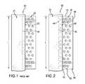
- FIG. 1is a partially schematic side view of a prior art core assembly.
- FIG. 2is a partially schematic side view of a revised core assembly.
- FIG. 3is an exploded view of the revised core assembly of FIG. 2 .
- FIG. 4is an enlarged exploded sectional view of a joint of the assembly of FIG. 3 .
- FIG. 5is a sectional view of an investment casting pattern.
- FIG. 6is a sectional view of a shell formed over the pattern of FIG. 5 .
- FIG. 7is a sectional view of a casting cast by the shell of FIG. 6 .
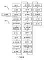
- FIG. 8is a flowchart of a core manufacturing process.
- FIG. 1shows an exemplary core assembly 20 including a ceramic feedcore 21 and an RMC 22 .
- the exemplary assemblyis illustrative of a feedcore forming a trailing edge slot for a blade or vane airfoil.
- a joint 23is formed by a leading region of the exemplary RMC 22 mounted in a trailing slot 24 in the feedcore 21 .
- the joint 23may further include a filler material (such as a hardened ceramic adhesive or slurry) at one or more locations between the RMC 22 and the ceramic feedcore 21 .
- the joint 23has a length L.
- a modified feedcore/RMC assembly 30is shown in FIGS. 2 and 3 .
- the modified ceramic feedcore 31may be formed by molding (e.g., as in the prior art).
- the modified RMC 32may be formed from sheetstock and have first and second faces 36 and 38 ( FIG. 3 ) for forming an exemplary trailing edge discharge slot.
- the exemplary RMC 32has first and second span-wise ends/edges (e.g., an inboard end 40 and an outboard end 42 ) and first and second streamwise ends/edges (e.g., a leading edge 44 and a trailing edge 46 ).
- a region 48 of the RMC(e.g., a portion near the leading end/edge 44 ) may be received by the feedcore.
- a region 50e.g., near the trailing end/edge 46
- a main portion 52 of the RMCmay cast the ultimate discharge slot.
- the region 48comprises a plurality of projections (tabs/tongues) 54 A- 54 M separated from each other by recesses 56 A- 56 L.
- the exemplary projectionsare unitarily formed with the main portion 52 by removing adjacent material from the refractory metal sheetstock. The removal may be part of the same process that forms additional holes/apertures 58 in the RMC main portion 52 (e.g., for casting posts in the ultimate discharge slot).
- the exemplary apertures 58are internal through-apertures. They are “internal” or “closed” in that they are not open to the lateral perimeters of the islands (e.g., along the leading and trailing edges, the inboard and outboard edges, or along the gaps).
- the RMC's mating region 48is received in a trailing region 70 of the feedcore.
- the exemplary trailing region (receiving region) 70comprises a subdivided compartment having individual recesses or compartments 72 A- 72 M at least partially separated from adjacent ones of each other by dividing walls 74 A- 74 L.
- FIG. 4shows each recess 72 A- 72 M as having a height (or height profile) H and a depth D.
- FIG. 3shows each compartment 72 A- 72 M as having a spanwise length or depth-dependent length profile L C .
- the exemplary embodimentmerges the compartments 72 A- 72 M along the small initial portion D 1 ( FIG. 4 ) of the total depth.
- Exemplary D 1is less than 50% of D (e.g., measured as an appropriate average such as a mean or median value), more narrowly, 5-20% of D.
- Exemplary L Cis 1.5-10 mm measured as such an average.
- a length of the projections 54 A- 54 Mmay be similar.
- FIG. 4further shows an RMC thickness T between the faces 36 and 38 .
- Exemplary Tmay be measured including any pre-applied coating.
- Tis 0.2-0.5 mm, more broadly 0.2-1.0 mm.
- Exemplary peak depth of the recesses 56 A- 56 Lis 300-500% of T.
- An exemplary thickness Tis 50-100% of H (e.g., measured as an appropriate average such as a mean or median value).
- FIG. 4further shows portions 80 and 82 of the feedcore on either side of the trailing region 70 . A depth-dependent thickness profile of these portions is shown as T 1 which may be different for each of the two.
- An exemplary feedcore thickness T 2 at its trailing edgeis 300-700% of H.
- Exemplary D 1is 100-200% of H.
- Exemplary on-center spacing or pitch S of the projections and recessesis at least 400% of H and may be effective to provide at least three projections and recesses.
- An exemplary characteristic wall width or span W(e.g., measured as a mean or median) is at least 200% of H and is less than 85% of S (e.g., 25-50% of S).
- Exemplary depth Dis 300-800% of H.
- An exemplary L c(e.g., median) may be 50-800% of D (e.g., median) along a majority of a total depth of the recesses 72 A- 72 M.
- the divided compartmentprovides a more distributed support to the regions 80 and 82 . Accordingly, it may provide greater flexibility in providing particularly small thicknesses T 1 and T 2 .
- FIG. 5shows a pattern 110 formed by the molding of wax over the core assembly.
- the waxincludes an airfoil portion 112 extending between a leading edge 113 and a trailing edge 114 and having a pressure side 115 and a suction side 116 .
- the patternmay further include portions for forming an outboard shroud and/or an inboard platform (not shown).
- FIG. 6is a sectional view showing the pattern airfoil after shelling with stucco 118 to form the shell 120 .
- FIG. 7shows the resulting casting 130 after deshelling and decoring.
- the castinghas an airfoil 132 having a pressure side 134 and a suction side 136 and extending from a leading edge 138 to a trailing edge 140 .
- the ceramic feedcore 21casts one or more feed passageways 150 and the RMC casts a discharge outlet slot 152 .
- Steps in the manufacture 200 of the core assemblyare broadly identified in the flowchart of FIG. 8 .
- a cutting operation 202e.g., laser cutting, electro-discharge machining (EDM), liquid jet machining, or stamping
- a cuttingis cut from a blank.
- the exemplary blankis of a refractory metal-based sheet stock (e.g., molybdenum or niobium) having the thickness T between parallel first and second faces and transverse dimensions much greater than that.
- the exemplary cuttinghas the cut features of the RMC including the projections and the holes 58 .
- a second step 204if appropriate, the cutting is bent. More complex forming procedures are also possible.
- the RMCmay be coated 206 with a protective coating.
- Suitable coating materialsinclude silica, alumina, zirconia, chromia, mullite and hafnia.
- CTEcoefficient of thermal expansion
- Coatingsmay be applied by any appropriate line-of sight or non-line-of sight technique (e.g., chemical or physical vapor deposition (CVD, PVD) methods, plasma spray methods, electrophoresis, and sol gel methods).
- Individual layersmay typically be 0.1 to 1 mil (2.5 to 25 micrometers) thick.
- Layers of Pt, other noble metals, Cr, Si, W, and/or Al, or other non-metallic materialsmay be applied to the metallic core elements for oxidation protection in combination with a ceramic coating for protection from molten metal erosion and dissolution.
- the RMCmay then be mated/assembled 208 to the feedcore.
- the feedcoremay be pre-molded 210 and, optionally, pre-fired.
- the slot or other mating featuremay be formed during that molding or subsequent cut.
- the RMC leading regionmay be inserted into the feedcore slot.
- a ceramic adhesive or other securing meansmay be used.
- An exemplary ceramic adhesiveis a colloid which may be dried by a microwave process.
- the feedcoremay be overmolded to the RMC.
- the RMCmay be placed in a die and the feedcore (e.g., silica-, zircon-, or alumina-based) molded thereover.
- An exemplary overmoldingis a freeze casting process. Although a conventional molding of a green ceramic followed by a de-bind/fire process may be used, the freeze casting process may have advantages regarding limiting degradation of the RMC and limiting ceramic core shrinkage.
- FIG. 8also shows an exemplary method 220 for investment casting using the composite core assembly.
- Other methodsare possible, including a variety of prior art methods and yet-developed methods.
- the core assemblyis then overmolded 230 with an easily sacrificed material such as a natural or synthetic wax (e.g., via placing the assembly in a mold and molding the wax around it). There may be multiple such assemblies involved in a given mold.
- the overmolded core assembly(or group of assemblies) forms a casting pattern with an exterior shape largely corresponding to the exterior shape of the part to be cast.
- the patternmay then be assembled 232 to a shelling fixture (e.g., via wax welding between end plates of the fixture).
- the patternmay then be shelled 234 (e.g., via one or more stages of slurry dipping, slurry spraying, or the like).
- the dryingprovides the shell with at least sufficient strength or other physical integrity properties to permit subsequent processing.
- the shell containing the invested core assemblymay be disassembled 238 fully or partially from the shelling fixture and then transferred 240 to a dewaxer (e.g., a steam autoclave).
- a dewaxere.g., a steam autoclave
- a steam dewax process 242removes a major portion of the wax leaving the core assembly secured within the shell.
- the shell and core assemblywill largely form the ultimate mold.
- the dewax processtypically leaves a wax or byproduct hydrocarbon residue on the shell interior and core assembly.
- the shellis transferred 244 to a furnace (e.g., containing air or other oxidizing atmosphere) in which it is heated 246 to strengthen the shell and remove any remaining wax residue (e.g., by vaporization) and/or converting hydrocarbon residue to carbon.
- Oxygen in the atmospherereacts with the carbon to form carbon dioxide. Removal of the carbon is advantageous to reduce or eliminate the formation of detrimental carbides in the metal casting. Removing carbon offers the additional advantage of reducing the potential for clogging the vacuum pumps used in subsequent stages of operation.
- the moldmay be removed from the atmospheric furnace, allowed to cool, and inspected 248 .
- the moldmay be seeded 250 by placing a metallic seed in the mold to establish the ultimate crystal structure of a directionally solidified (DS) casting or a single-crystal (SX) casting. Nevertheless the present teachings may be applied to other DS and SX casting techniques (e.g., wherein the shell geometry defines a grain selector) or to casting of other microstructures.
- the moldmay be transferred 252 to a casting furnace (e.g., placed atop a chill plate in the furnace).
- the casting furnacemay be pumped down to vacuum 254 or charged with a non-oxidizing atmosphere (e.g., inert gas) to prevent oxidation of the casting alloy.
- the casting furnaceis heated 256 to preheat the mold. This preheating serves two purposes: to further harden and strengthen the shell; and to preheat the shell for the introduction of molten alloy to prevent thermal shock and premature solidification of the alloy.
- the molten alloyis poured 258 into the mold and the mold is allowed to cool to solidify 260 the alloy (e.g., after withdrawal from the furnace hot zone).
- the vacuummay be broken 262 and the chilled mold removed 264 from the casting furnace.
- the shellmay be removed in a deshelling process 266 (e.g., mechanical breaking of the shell).
- the core assemblyis removed in a decoring process 268 to leave a cast article (e.g., a metallic precursor of the ultimate part).
- the cast articlemay be machined 270 , chemically and/or thermally treated 272 and coated 274 to form the ultimate part. Some or all of any machining or chemical or thermal treatment may be performed before the decoring.
Landscapes
- Engineering & Computer Science (AREA)
- Mechanical Engineering (AREA)
- Molds, Cores, And Manufacturing Methods Thereof (AREA)
Abstract
Description
Claims (21)
Priority Applications (2)
| Application Number | Priority Date | Filing Date | Title |
|---|---|---|---|
| US12/271,980US8100165B2 (en) | 2008-11-17 | 2008-11-17 | Investment casting cores and methods |
| EP09252636.7AEP2191911B1 (en) | 2008-11-17 | 2009-11-17 | Investment casting cores and methods |
Applications Claiming Priority (1)
| Application Number | Priority Date | Filing Date | Title |
|---|---|---|---|
| US12/271,980US8100165B2 (en) | 2008-11-17 | 2008-11-17 | Investment casting cores and methods |
Publications (2)
| Publication Number | Publication Date |
|---|---|
| US20100122789A1 US20100122789A1 (en) | 2010-05-20 |
| US8100165B2true US8100165B2 (en) | 2012-01-24 |
Family
ID=41664858
Family Applications (1)
| Application Number | Title | Priority Date | Filing Date |
|---|---|---|---|
| US12/271,980Active2029-12-26US8100165B2 (en) | 2008-11-17 | 2008-11-17 | Investment casting cores and methods |
Country Status (2)
| Country | Link |
|---|---|
| US (1) | US8100165B2 (en) |
| EP (1) | EP2191911B1 (en) |
Cited By (13)
| Publication number | Priority date | Publication date | Assignee | Title |
|---|---|---|---|---|
| US20160017724A1 (en)* | 2013-04-03 | 2016-01-21 | United Technologies Corporation | Variable thickness trailing edge cavity and method of making |
| US9579714B1 (en) | 2015-12-17 | 2017-02-28 | General Electric Company | Method and assembly for forming components having internal passages using a lattice structure |
| US9968991B2 (en) | 2015-12-17 | 2018-05-15 | General Electric Company | Method and assembly for forming components having internal passages using a lattice structure |
| US9987677B2 (en) | 2015-12-17 | 2018-06-05 | General Electric Company | Method and assembly for forming components having internal passages using a jacketed core |
| US10046389B2 (en) | 2015-12-17 | 2018-08-14 | General Electric Company | Method and assembly for forming components having internal passages using a jacketed core |
| US10099284B2 (en) | 2015-12-17 | 2018-10-16 | General Electric Company | Method and assembly for forming components having a catalyzed internal passage defined therein |
| US10099276B2 (en) | 2015-12-17 | 2018-10-16 | General Electric Company | Method and assembly for forming components having an internal passage defined therein |
| US10099283B2 (en) | 2015-12-17 | 2018-10-16 | General Electric Company | Method and assembly for forming components having an internal passage defined therein |
| US10118217B2 (en) | 2015-12-17 | 2018-11-06 | General Electric Company | Method and assembly for forming components having internal passages using a jacketed core |
| US10137499B2 (en) | 2015-12-17 | 2018-11-27 | General Electric Company | Method and assembly for forming components having an internal passage defined therein |
| US10150158B2 (en) | 2015-12-17 | 2018-12-11 | General Electric Company | Method and assembly for forming components having internal passages using a jacketed core |
| US10286450B2 (en) | 2016-04-27 | 2019-05-14 | General Electric Company | Method and assembly for forming components using a jacketed core |
| US10335853B2 (en) | 2016-04-27 | 2019-07-02 | General Electric Company | Method and assembly for forming components using a jacketed core |
Families Citing this family (18)
| Publication number | Priority date | Publication date | Assignee | Title |
|---|---|---|---|---|
| US8353329B2 (en) | 2010-05-24 | 2013-01-15 | United Technologies Corporation | Ceramic core tapered trip strips |
| US20110315336A1 (en)* | 2010-06-25 | 2011-12-29 | United Technologies Corporation | Contoured Metallic Casting Core |
| US8251123B2 (en) | 2010-12-30 | 2012-08-28 | United Technologies Corporation | Casting core assembly methods |
| US9403208B2 (en) | 2010-12-30 | 2016-08-02 | United Technologies Corporation | Method and casting core for forming a landing for welding a baffle inserted in an airfoil |
| US8899303B2 (en)* | 2011-05-10 | 2014-12-02 | Howmet Corporation | Ceramic core with composite insert for casting airfoils |
| US20130026338A1 (en)* | 2011-07-28 | 2013-01-31 | Lea Kennard Castle | Rapid casting article manufacturing |
| US8561668B2 (en)* | 2011-07-28 | 2013-10-22 | United Technologies Corporation | Rapid manufacturing method |
| US8291963B1 (en) | 2011-08-03 | 2012-10-23 | United Technologies Corporation | Hybrid core assembly |
| US20140102656A1 (en)* | 2012-10-12 | 2014-04-17 | United Technologies Corporation | Casting Cores and Manufacture Methods |
| US20140182809A1 (en)* | 2012-12-28 | 2014-07-03 | United Technologies Corporation | Mullite-containing investment casting core |
| WO2015060989A1 (en) | 2013-10-24 | 2015-04-30 | United Technologies Corporation | Lost core molding cores for forming cooling passages |
| US10166599B2 (en)* | 2013-11-18 | 2019-01-01 | United Technologies Corporation | Coated casting cores and manufacture methods |
| US10300526B2 (en) | 2014-02-28 | 2019-05-28 | United Technologies Corporation | Core assembly including studded spacer |
| US20190022757A1 (en)* | 2017-07-19 | 2019-01-24 | United Technologies Corporation | Linkage of composite core features |
| DE102018200705A1 (en)* | 2018-01-17 | 2019-07-18 | Flc Flowcastings Gmbh | Method for producing a ceramic core for producing a cavity-type casting and ceramic core |
| US11312053B2 (en) | 2019-08-13 | 2022-04-26 | Honeywell International Inc. | Internal relief void arrangement for casting system |
| US11440146B1 (en) | 2021-04-22 | 2022-09-13 | Raytheon Technologies Corporation | Mini-core surface bonding |
| FR3142920B1 (en)* | 2022-12-08 | 2025-05-02 | Safran | Foundry core |
Citations (12)
| Publication number | Priority date | Publication date | Assignee | Title |
|---|---|---|---|---|
| US3957104A (en)* | 1974-02-27 | 1976-05-18 | The United States Of America As Represented By The Administrator Of The United States National Aeronautics And Space Administration | Method of making an apertured casting |
| US4542867A (en) | 1983-01-31 | 1985-09-24 | United Technologies Corporation | Internally cooled hollow airfoil |
| US6637500B2 (en)* | 2001-10-24 | 2003-10-28 | United Technologies Corporation | Cores for use in precision investment casting |
| US20040202542A1 (en)* | 2003-04-08 | 2004-10-14 | Cunha Frank J. | Turbine element |
| US6929054B2 (en) | 2003-12-19 | 2005-08-16 | United Technologies Corporation | Investment casting cores |
| US20060239819A1 (en) | 2005-04-22 | 2006-10-26 | United Technologies Corporation | Airfoil trailing edge cooling |
| US7134475B2 (en) | 2004-10-29 | 2006-11-14 | United Technologies Corporation | Investment casting cores and methods |
| US20070044933A1 (en) | 2005-09-01 | 2007-03-01 | United Technologies Corporation | Investment casting pattern manufacture |
| US7270173B2 (en) | 2004-09-09 | 2007-09-18 | United Technologies Corporation | Composite core for use in precision investment casting |
| EP1857199A1 (en) | 2006-05-15 | 2007-11-21 | United Technologies Corporation | Investment Casting Core Assembly |
| US20080145235A1 (en) | 2006-12-18 | 2008-06-19 | United Technologies Corporation | Airfoil cooling with staggered refractory metal core microcircuits |
| US7413403B2 (en) | 2005-12-22 | 2008-08-19 | United Technologies Corporation | Turbine blade tip cooling |
- 2008
- 2008-11-17USUS12/271,980patent/US8100165B2/enactiveActive
- 2009
- 2009-11-17EPEP09252636.7Apatent/EP2191911B1/enactiveActive
Patent Citations (14)
| Publication number | Priority date | Publication date | Assignee | Title |
|---|---|---|---|---|
| US3957104A (en)* | 1974-02-27 | 1976-05-18 | The United States Of America As Represented By The Administrator Of The United States National Aeronautics And Space Administration | Method of making an apertured casting |
| US4542867A (en) | 1983-01-31 | 1985-09-24 | United Technologies Corporation | Internally cooled hollow airfoil |
| US6637500B2 (en)* | 2001-10-24 | 2003-10-28 | United Technologies Corporation | Cores for use in precision investment casting |
| US7014424B2 (en) | 2003-04-08 | 2006-03-21 | United Technologies Corporation | Turbine element |
| US20040202542A1 (en)* | 2003-04-08 | 2004-10-14 | Cunha Frank J. | Turbine element |
| US7270170B2 (en) | 2003-12-19 | 2007-09-18 | United Technologies Corporation | Investment casting core methods |
| US6929054B2 (en) | 2003-12-19 | 2005-08-16 | United Technologies Corporation | Investment casting cores |
| US7270173B2 (en) | 2004-09-09 | 2007-09-18 | United Technologies Corporation | Composite core for use in precision investment casting |
| US7134475B2 (en) | 2004-10-29 | 2006-11-14 | United Technologies Corporation | Investment casting cores and methods |
| US20060239819A1 (en) | 2005-04-22 | 2006-10-26 | United Technologies Corporation | Airfoil trailing edge cooling |
| US20070044933A1 (en) | 2005-09-01 | 2007-03-01 | United Technologies Corporation | Investment casting pattern manufacture |
| US7413403B2 (en) | 2005-12-22 | 2008-08-19 | United Technologies Corporation | Turbine blade tip cooling |
| EP1857199A1 (en) | 2006-05-15 | 2007-11-21 | United Technologies Corporation | Investment Casting Core Assembly |
| US20080145235A1 (en) | 2006-12-18 | 2008-06-19 | United Technologies Corporation | Airfoil cooling with staggered refractory metal core microcircuits |
Non-Patent Citations (1)
| Title |
|---|
| European Search Report for EP Patent Application No. 09252636.7, dated Feb. 24, 2010. |
Cited By (16)
| Publication number | Priority date | Publication date | Assignee | Title |
|---|---|---|---|---|
| US20160017724A1 (en)* | 2013-04-03 | 2016-01-21 | United Technologies Corporation | Variable thickness trailing edge cavity and method of making |
| EP2981677A4 (en)* | 2013-04-03 | 2016-06-22 | United Technologies Corp | Variable thickness trailing edge cavity and method of making |
| US9579714B1 (en) | 2015-12-17 | 2017-02-28 | General Electric Company | Method and assembly for forming components having internal passages using a lattice structure |
| US9968991B2 (en) | 2015-12-17 | 2018-05-15 | General Electric Company | Method and assembly for forming components having internal passages using a lattice structure |
| US9975176B2 (en) | 2015-12-17 | 2018-05-22 | General Electric Company | Method and assembly for forming components having internal passages using a lattice structure |
| US9987677B2 (en) | 2015-12-17 | 2018-06-05 | General Electric Company | Method and assembly for forming components having internal passages using a jacketed core |
| US10046389B2 (en) | 2015-12-17 | 2018-08-14 | General Electric Company | Method and assembly for forming components having internal passages using a jacketed core |
| US10099284B2 (en) | 2015-12-17 | 2018-10-16 | General Electric Company | Method and assembly for forming components having a catalyzed internal passage defined therein |
| US10099276B2 (en) | 2015-12-17 | 2018-10-16 | General Electric Company | Method and assembly for forming components having an internal passage defined therein |
| US10099283B2 (en) | 2015-12-17 | 2018-10-16 | General Electric Company | Method and assembly for forming components having an internal passage defined therein |
| US10118217B2 (en) | 2015-12-17 | 2018-11-06 | General Electric Company | Method and assembly for forming components having internal passages using a jacketed core |
| US10137499B2 (en) | 2015-12-17 | 2018-11-27 | General Electric Company | Method and assembly for forming components having an internal passage defined therein |
| US10150158B2 (en) | 2015-12-17 | 2018-12-11 | General Electric Company | Method and assembly for forming components having internal passages using a jacketed core |
| US10286450B2 (en) | 2016-04-27 | 2019-05-14 | General Electric Company | Method and assembly for forming components using a jacketed core |
| US10335853B2 (en) | 2016-04-27 | 2019-07-02 | General Electric Company | Method and assembly for forming components using a jacketed core |
| US10981221B2 (en) | 2016-04-27 | 2021-04-20 | General Electric Company | Method and assembly for forming components using a jacketed core |
Also Published As
| Publication number | Publication date |
|---|---|
| US20100122789A1 (en) | 2010-05-20 |
| EP2191911A1 (en) | 2010-06-02 |
| EP2191911B1 (en) | 2018-08-01 |
Similar Documents
| Publication | Publication Date | Title |
|---|---|---|
| US8100165B2 (en) | Investment casting cores and methods | |
| US8137068B2 (en) | Castings, casting cores, and methods | |
| US7753104B2 (en) | Investment casting cores and methods | |
| EP2511024B1 (en) | Contoured metallic casting core | |
| US8171978B2 (en) | Castings, casting cores, and methods | |
| US8113780B2 (en) | Castings, casting cores, and methods | |
| EP1992431B1 (en) | Investment casting cores and methods | |
| US8251123B2 (en) | Casting core assembly methods | |
| EP1857199B1 (en) | Investment casting core assembly | |
| US10166599B2 (en) | Coated casting cores and manufacture methods | |
| EP2399693B1 (en) | Contoured metallic casting core |
Legal Events
| Date | Code | Title | Description |
|---|---|---|---|
| AS | Assignment | Owner name:UNITED TECHNOLOGIES CORPORATION,CONNECTICUT Free format text:ASSIGNMENT OF ASSIGNORS INTEREST;ASSIGNORS:PIGGUSH, JUSTIN D.;MENTZ, KARL A.;PAGE, RICHARD H.;AND OTHERS;SIGNING DATES FROM 20081113 TO 20081114;REEL/FRAME:021842/0110 Owner name:UNITED TECHNOLOGIES CORPORATION, CONNECTICUT Free format text:ASSIGNMENT OF ASSIGNORS INTEREST;ASSIGNORS:PIGGUSH, JUSTIN D.;MENTZ, KARL A.;PAGE, RICHARD H.;AND OTHERS;SIGNING DATES FROM 20081113 TO 20081114;REEL/FRAME:021842/0110 | |
| STCF | Information on status: patent grant | Free format text:PATENTED CASE | |
| FPAY | Fee payment | Year of fee payment:4 | |
| MAFP | Maintenance fee payment | Free format text:PAYMENT OF MAINTENANCE FEE, 8TH YEAR, LARGE ENTITY (ORIGINAL EVENT CODE: M1552); ENTITY STATUS OF PATENT OWNER: LARGE ENTITY Year of fee payment:8 | |
| AS | Assignment | Owner name:RAYTHEON TECHNOLOGIES CORPORATION, MASSACHUSETTS Free format text:CHANGE OF NAME;ASSIGNOR:UNITED TECHNOLOGIES CORPORATION;REEL/FRAME:054062/0001 Effective date:20200403 | |
| AS | Assignment | Owner name:RAYTHEON TECHNOLOGIES CORPORATION, CONNECTICUT Free format text:CORRECTIVE ASSIGNMENT TO CORRECT THE AND REMOVE PATENT APPLICATION NUMBER 11886281 AND ADD PATENT APPLICATION NUMBER 14846874. TO CORRECT THE RECEIVING PARTY ADDRESS PREVIOUSLY RECORDED AT REEL: 054062 FRAME: 0001. ASSIGNOR(S) HEREBY CONFIRMS THE CHANGE OF ADDRESS;ASSIGNOR:UNITED TECHNOLOGIES CORPORATION;REEL/FRAME:055659/0001 Effective date:20200403 | |
| MAFP | Maintenance fee payment | Free format text:PAYMENT OF MAINTENANCE FEE, 12TH YEAR, LARGE ENTITY (ORIGINAL EVENT CODE: M1553); ENTITY STATUS OF PATENT OWNER: LARGE ENTITY Year of fee payment:12 | |
| AS | Assignment | Owner name:RTX CORPORATION, CONNECTICUT Free format text:CHANGE OF NAME;ASSIGNOR:RAYTHEON TECHNOLOGIES CORPORATION;REEL/FRAME:064714/0001 Effective date:20230714 |