US8100125B2 - Venturi geometry design for flow-generator patient circuit - Google Patents
Venturi geometry design for flow-generator patient circuitDownload PDFInfo
- Publication number
- US8100125B2 US8100125B2US11/241,303US24130305AUS8100125B2US 8100125 B2US8100125 B2US 8100125B2US 24130305 AUS24130305 AUS 24130305AUS 8100125 B2US8100125 B2US 8100125B2
- Authority
- US
- United States
- Prior art keywords
- patient
- passageways
- supply
- universal interface
- pressure
- Prior art date
- Legal status (The legal status is an assumption and is not a legal conclusion. Google has not performed a legal analysis and makes no representation as to the accuracy of the status listed.)
- Active, expires
Links
- 238000013461designMethods0.000titledescription4
- 230000029058respiratory gaseous exchangeEffects0.000claimsabstractdescription45
- 238000009530blood pressure measurementMethods0.000claimsdescription6
- 238000011513continuous positive airway pressure therapyMethods0.000description19
- 230000002829reductive effectEffects0.000description11
- 239000000463materialSubstances0.000description8
- 239000012530fluidSubstances0.000description7
- 210000004072lungAnatomy0.000description6
- 239000008186active pharmaceutical agentSubstances0.000description5
- 238000004891communicationMethods0.000description5
- 230000007812deficiencyEffects0.000description4
- 239000000853adhesiveSubstances0.000description2
- 230000001070adhesive effectEffects0.000description2
- 230000006378damageEffects0.000description2
- 230000003434inspiratory effectEffects0.000description2
- 230000000670limiting effectEffects0.000description2
- 230000002093peripheral effectEffects0.000description2
- 230000002269spontaneous effectEffects0.000description2
- 238000009423ventilationMethods0.000description2
- 229920004142LEXAN™Polymers0.000description1
- 239000004418LexanSubstances0.000description1
- 208000019693Lung diseaseDiseases0.000description1
- 208000007123Pulmonary AtelectasisDiseases0.000description1
- 208000027418Wounds and injuryDiseases0.000description1
- 230000000295complement effectEffects0.000description1
- 230000003247decreasing effectEffects0.000description1
- 230000001771impaired effectEffects0.000description1
- 238000001746injection mouldingMethods0.000description1
- 208000014674injuryDiseases0.000description1
- 238000004519manufacturing processMethods0.000description1
- 239000012528membraneSubstances0.000description1
- 238000012986modificationMethods0.000description1
- 230000004048modificationEffects0.000description1
- 210000000056organAnatomy0.000description1
- 230000036961partial effectEffects0.000description1
- 230000000241respiratory effectEffects0.000description1
- 230000000717retained effectEffects0.000description1
- 238000012360testing methodMethods0.000description1
- 230000003519ventilatory effectEffects0.000description1
- 238000003466weldingMethods0.000description1
Images


Classifications
- A—HUMAN NECESSITIES
- A61—MEDICAL OR VETERINARY SCIENCE; HYGIENE
- A61M—DEVICES FOR INTRODUCING MEDIA INTO, OR ONTO, THE BODY; DEVICES FOR TRANSDUCING BODY MEDIA OR FOR TAKING MEDIA FROM THE BODY; DEVICES FOR PRODUCING OR ENDING SLEEP OR STUPOR
- A61M16/00—Devices for influencing the respiratory system of patients by gas treatment, e.g. ventilators; Tracheal tubes
- A61M16/06—Respiratory or anaesthetic masks
- A61M16/0666—Nasal cannulas or tubing
- A—HUMAN NECESSITIES
- A61—MEDICAL OR VETERINARY SCIENCE; HYGIENE
- A61M—DEVICES FOR INTRODUCING MEDIA INTO, OR ONTO, THE BODY; DEVICES FOR TRANSDUCING BODY MEDIA OR FOR TAKING MEDIA FROM THE BODY; DEVICES FOR PRODUCING OR ENDING SLEEP OR STUPOR
- A61M16/00—Devices for influencing the respiratory system of patients by gas treatment, e.g. ventilators; Tracheal tubes
- A61M16/0003—Accessories therefor, e.g. sensors, vibrators, negative pressure
- A61M16/0009—Accessories therefor, e.g. sensors, vibrators, negative pressure with sub-atmospheric pressure, e.g. during expiration
- A61M16/0012—Accessories therefor, e.g. sensors, vibrators, negative pressure with sub-atmospheric pressure, e.g. during expiration by Venturi means
- A—HUMAN NECESSITIES
- A61—MEDICAL OR VETERINARY SCIENCE; HYGIENE
- A61M—DEVICES FOR INTRODUCING MEDIA INTO, OR ONTO, THE BODY; DEVICES FOR TRANSDUCING BODY MEDIA OR FOR TAKING MEDIA FROM THE BODY; DEVICES FOR PRODUCING OR ENDING SLEEP OR STUPOR
- A61M16/00—Devices for influencing the respiratory system of patients by gas treatment, e.g. ventilators; Tracheal tubes
- A61M16/08—Bellows; Connecting tubes ; Water traps; Patient circuits
- A61M16/0816—Joints or connectors
- A61M16/0841—Joints or connectors for sampling
- A61M16/0858—Pressure sampling ports
Definitions
- the present inventionrelates generally to a breathing apparatus.
- the present inventionrelates generally to breathing apparatus and, more particularly, to a universal interface for a breathing apparatus which is specifically adapted to provide continuous positive airway pressure (CPAP) when the interface is used with a standard ventilator and which further is constructed with unique geometries to increase stagnation pressure (i.e., patient pressure) with minimal supply pressure as well as reduced exhalation resistance in order to improve the work of breathing.
- CPAPcontinuous positive airway pressure
- breathing apparatusupon respiratory-impaired patients is well known.
- such apparatusesassist in patient breathing by allowing proper exchange of inhaled and exhaled gas while providing pressurized gasses to a patient's lungs so as to prevent lung collapse.
- conventional breathing apparatusoperate to allow spontaneous breathing of the patient while sustaining the application of continuous positive airway pressure (CPAP) to the patient's lungs.
- CPAPcontinuous positive airway pressure
- CPAP therapydelivers a constant stable pressure to the mouth, nose or via a tracheal tube inserted in the infant.
- flow generatorsare a type of device that can be used with the above-mentioned breathing apparatus in providing CPAP therapy treatment.
- CPAP ventilationhigh pressure gas must be supplied to the airways of the patient on a constant basis.
- a flow generatormay be used with a conventional ventilator.
- conventional ventilatorstypically operate at a lower pressure than the pressure required for CPAP therapy treatment.
- prior art flow generatorsrequire the use of excessive supply pressure in order to create sufficient pressure at the patient. More particularly, it is understood that such prior art flow generators require up to 205 centimeters of H 2 O of supply pressure in order to create up to about 10 to 15 cm of H 2 O at the patient.
- federal standardslimit the amount of supply pressure that can be utilized in CPAP therapy for certain patients. For example, in neonates, the recommended maximum supply pressure is limited to 120 centimeters (cm) of H2O.
- prior art flow generatorsrequire high supply pressure (e.g., 205 cm of H2O) in order to achieve a desired flow rate of 12 liters/minute (LPM) to the patient.
- a universal interfacethat may be adapted for providing continuous positive airway pressure (CPAP) with reduced supply gas pressure in order to minimize the risks posed by excessive pressures in the patient's airway.
- CPAPcontinuous positive airway pressure
- a universal interface for CPAP ventilationthat is configured to operate with a standard ventilator at a supply pressure of no greater than about 120 cm of H2O in order to provide up to about 15 cm of H2O at the patient, depending on the supply pressure.
- a universal interface for CPAP therapythat is configured to provide a flow rate of up to about 12 liters/minute to the patient while the supply pressure is limited to 120 cm of H2O.
- a universal interface for CPAP therapythat is of simple and thereby inexpensive design and which is specifically configured to sustain a positive airway pressure at the patient with minimal supply pressure while reducing exhalation resistance in order to improve the work of breathing.
- the present inventionspecifically addresses and alleviates the above referenced deficiencies associated with flow generators of the prior art. More particularly, the present invention is a universal interface that is adapted for providing continuous positive airway pressure (CPAP) with reduced supply gas pressure as compared to flow generators of the prior art. In this manner, the universal interface of the present invention minimizes risks posed by excessive pressure in the patient's airways.
- CPAPcontinuous positive airway pressure
- the universal interface of the present inventionis specifically configured to operate with a standard ventilator at a maximum supply pressure of about 120 centimeters (cm) of H 2 O in order to deliver pressure to the patient of up to about 15 cm of H 2 O at a flow rate of up to about 12 liters/minute.
- the universal interfaceas presently constructed provides increased efficiency in that it operates with the reduced supply pressure while still providing a constant positive pressure within the patient's airways.
- the universal interfaceaccomplishes the above with minimal pressure resistance during inhalation and exhalation phases of breathing at the patient.
- the universal interfaceincludes a pair of exhalation passageways and supply passageways which are each provided with a taper portion.
- the taper portionis specifically configured to minimize pressure resistance during inhalation and exhalation.
- the universal interfacemay be configured for either non-invasive or invasive CPAP therapy.
- non-invasive CPAP therapywith the universal interface may be facilitated with the use of a nose piece member or a face mask such as mounted on a patient's head.
- the universal interfacemay be adapted for invasive CPAP therapy wherein a tracheal tube may be inserted into the patient to provide air to the patient's lungs.
- the nose piece memberis preferably formed of a soft, elastic polymeric material that provides a comfortable surface against the patient's skin. Air is directed into the patient's nose through a pair of nostril engaging stems formed in the nose piece member that provide an efficient fluid path between the patient's nose and the universal interface.
- the nostril engaging stemsinclude a peripheral wall having a D-shaped configuration to anatomically conform to the patient's nostrils.
- the universal interfacemay include a pressure tube and a supply tube which extends from opposite sides thereof.
- the supply tubemay be included with the universal interface to supply gas from a gas source to the patient during CPAP therapy.
- the pressure tubeis included to provide a means by which pressure may be measured during breathing of the patient.
- a pressure fitting and a supply fittingmay be included with the universal interface in order to facilitate mounting of the pressure tube and supply tube, respectively.
- the interface bodymay be comprised of a spaced pair of generally parallel breathing passageways.
- a corresponding pair of supply passagewaysare also included with the universal interface and are fluidly connected to respective ones of the breathing passageways.
- the interface bodymay also have a spaced pair of exhalation passageways that are also fluidly connected to respective ones of the breathing passageways.
- the supply passagewaysmay be generally coaxially aligned the breathing passageway to facilitate in-flow of supply gas.
- Each one of the breathing passagewaysis comprised of the patient passageway which terminates at a pair of patient ports to which the nostril engaging stems of the nose piece member connect.
- the exhalation passagewaysintersect the patient passageways to collectively form the breathing passageways.
- the patient passagewaysmay intersect the exhalation passageways at an angle of from about 20° to about 60° although any angle may be utilized.
- Each one of the supply passagewaysis configured to introduce pressurized gas into the patient passageways such as during the inspiration phase of the breathing cycle.
- a supply manifoldmay be integrally formed with the universal interface in order to supply pressure to the breathing passageways.
- the supply manifoldmay have the supply passageways extending therefrom which are configured to introduce pressurized gas to an interior of each of the supply passageways and, ultimately, into the patient passageways. Because the supply manifold is in fluid communication with the gas source via the supply tube, the supply manifold receives the pressurized gas therefrom and introduces the gas into the patient passageways via the pair of jet venturis.
- each one of the jet venturisinclude the tapered geometry for performance enhancement.
- each one of the jet venturistapers outwardly along a direction from the supply manifold toward the patient passageway.
- the taper angle of the taper portionis in the range from about 0.5° to about 10° and is preferably about 2.5° .
- the jet venturimay have a conical shape and, in this regard, the taper portion defines a minor diameter.
- the supply passagewaysmay be configured in a variety of cross-sectional shapes such as rectangular, oval, or a generally rounded shape.
- the taper portion of each one of the jet venturispreferably has a length that is in the range of from about 0.25 to about 3 times the minor diameter of the taper portion.
- a constant section portionmay additionally be provided in at least one of the jet venturis along with the taper portion. If included, the constant section portion defines a length that is preferably in the range of from about 2.5 to about 2 times the minor diameter.
- Each one of the exhalation passagewaysalso preferably includes a taper portion that tapers outwardly along a direction from the patient passageway toward the exhalation port.
- the taper portion of each one of the exhalation passagewayspreferably has a taper angle which is in the range from about 0.5° to about 10° and which preferably is about 5°.
- the exhalation passagewaymay have a generally rectangular cross-sectional shape although other cross-sectional shapes may be used such as circular, oval, etc.
- the taper portiondefines a minor width occurring at an intersection of the exhalation passageway with a corresponding one of the patient passageways.
- the exhalation passageway taper portionpreferably defines a length that is in the range of from about 0.25 to about 3 times the minor width of the exhalation passageway taper portion.
- a constant section portionmay optionally be provided along with the taper portion in the exhalation passageways. If included, the constant section portion has a minor width that is preferably equivalent to that of the taper portion and has a length that is in the range of from about 0.25 to about 2 times the minor width.
- the universal interfacemay further include a pressure passageway which is provided for the purpose of measuring pressure at the patient airways.
- pressure transducersmay be placed in fluid communication with the pressure passageway such that pressure of the patient may be measured.
- FIG. 1is a perspective view of a universal interface of the present invention as utilized on a patient's face;
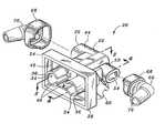
- FIG. 2is an exploded perspective view of the universal interface as worn by the patient shown in FIG. 1 and illustrating an interface body having a supply fitting and a pressure fitting attachable to the interface body and having supply and pressure tubes extending, respectively, therefrom along the patient's head;
- FIG. 3is a perspective view of the universal interface in an orientation illustrating an exhalation manifold that is integrally formed into the interface body;
- FIG. 4 ais a cross-sectional view taken along line 4 - 4 of FIG. 2 and illustrating an exhalation passageway and a jet venturi each having tapered portions which are specifically configured to minimize supply pressure and reduce exhalation resistance, respectively;
- FIG. 4 bis a cross-sectional view of the interface body taken along line 4 - 4 and illustrating the exhalation passageway and jet venturi having a constant section portion in addition to the taper portion;
- FIG. 5is a top cross-sectional view of the interface of FIG. 2 and illustrating a supply passageway having a pair of the jet venturis extending therefrom and being coaxially aligned with the patient passageways;
- FIG. 6is a side view of the interface body illustrating the relative orientations of the exhalation manifold and pressure manifold;
- FIG. 7is a front view of the interface body illustrating a well portion surrounding the pair of patient passageways and further illustrating a pressure passageway opening into the well portion and being located between the pair of patient passageways;
- FIG. 8is a partial cross-sectional top view of the interface body illustrating an L-shaped pressure passageway extending from the well portion of the interface body to a pressure port of the interface body.
- FIG. 1perceptively illustrates the universal interface 20 as applied to an infant patient 12 .
- the universal interface 20includes a pressure tube 72 and a supply tube 74 attached on opposite sides of the universal interface 20 and extending around the patient's 12 head.
- the universal interface 20 of the present inventionis specifically adapted to provide continuous positive airway pressure (CPAP) to the patient 12 at a reduced supply pressure when the universal interface 20 is used with a standard ventilator.
- CPAPcontinuous positive airway pressure
- the universal interface 20is specifically configured to operate at a pressure no greater than about 120 centimeters (cm) of H 2 O in order to deliver pressure to the patient of up to about 10 to 15 cm of H 2 O at a flow rate of up to about 12 liters/minute.
- the universal interface 20 of the present inventionprovides increased efficiency in that it requires decreased supply pressure in order to provide a constant positive pressure within the patient's 12 airway.
- the universal interface 20is specifically configured to minimize pressure resistance during inhalation and exhalation phases of breathing. The universal interface 20 facilitates this by reducing the required supply pressure of operation down to no greater than about 120 centimeters of H 2 O.
- the universal interface 20accomplishes the reduced operating pressure by including a unique taper geometry within a pair of exhalation passageways 64 as well as in a corresponding pair of jet venturis 56 that interconnect a supply manifold 50 to a pair of patient passageways 38 .
- the universal interface 20may be configured for use in a non-invasive CPAP application such as using a mouth adapter or a nose piece member 16 as shown in FIG. 1 .
- the nose piece member 16may be mounted on the universal interface 20 and is preferably configured to anatomically conform to the patient's 12 nostrils 14 such as the nostrils 14 of the infant shown in FIG. 1 .
- the nose piece member 16is preferably formed of an elastic polymeric material so as to provide a soft membrane between the universal interface 20 and the patient's 12 face.
- the nose piece member 16preferably includes a pair of outwardly extending nostril engaging stems each having an axially extending aperture which is formed through the nose piece member 16 .
- the nostril engaging stemsallow for fluid communication to the patient passageways 38 of the universal interface 20 .
- the nose piece member 16is also preferably configured to be removably engaged to and retained within a well portion 28 of the universal interface 20 via frictional fit or via other means of securement such as adhesive or mechanical interconnection.
- the nostril engaging stems which outwardly protrude from the interfaceare provided with a peripheral wall having a D-shaped configuration to anatomically conform to the patient's 12 nostrils 14 .
- the nose piece member 16 that may be included with the present inventionis similar to that shown and described in published U.S. Patent Application Publication No. 20030200970, filed Oct. 30, 2003 by Stenzler et al. and which is entitled, Infant Breathing Assist Apparatus, the entire contents of which is expressly incorporated by reference herein.
- the universal interface 20 of the present inventionis also preferably configured for use in invasive CPAP applications such as wherein a tracheal tube may be inserted into the patient.
- the tracheal tubemay be used in conjunction with the universal interface 20 in applying CPAP therapy treatment.
- the universal interface 20may be more commonly utilized in non-invasive CPAP therapy.
- the nose piece member 16 or a mask interfacemay be disposed on the nose and/or mouth of the patient 12 .
- the interface 20is specifically configured to minimize pressure to no greater than about 120 centimeters of H2O in order to deliver pressure to the patient of up to about 10 to 15 cm of H 2 O.
- the universal interface 20may be mounted on the patient 12 and may have the pressure tube 72 extending from one side of the universal interface 20 .
- the supply tube 74may extend from an opposite side of the universal interface 20 .
- the supply tube 74is configured to supply gas from a gas source 76 to the patient 12 during CPAP therapy.
- the pressure tube 72is provided to allow for a means of measuring pressure during breathing at the patient 12 . Such pressure measurement may be facilitated using a pressure transducer or other pressure measurement instruments.
- FIG. 2shown is the universal interface 20 in a perspective view wherein the universal interface 20 includes an interface body 22 .
- FIG. 2also illustrates a supply fitting 66 and a pressure fitting 70 disposed on opposite sides of the interface body 22 .
- the pressure tube 72may be interconnected to the interface body 22 using the pressure fitting 70 while the supply tube 74 may be interconnected to the interface body 22 using the supply fitting 66 .
- Flanges 68may be provided on the supply fitting 66 as well as on the pressure fitting 70 in order to facilitate interconnection thereof to the interface body 22 .
- the interface body 22is sized and configured complementary to the flanges 68 of the supply and pressure fittings 66 , 70 to facilitate mounting thereupon.
- the supply and pressure fittings 66 , 70may be connected to the interface body 22 using a variety of means including, but not limited to, sonic welding, adhesive and frictional fit.
- assembly and manufacturer of the universal interface 20is facilitated by providing the supply and pressure fittings 66 , 70 as separate components from the interface body 22 .
- the interface body 22which, in its broadest sense, may be comprised of a spaced pair of breathing passageways 34 having a corresponding pair of the supply passageways 54 fluidly connected thereto and having the pair of exhalation passageways 64 fluidly connected to the breathing passageways 34 .
- the pair of supply passageways 54may be generally aligned with the breathing passageways 34 .
- the supply passageways 54may be coaxial with the breathing passageways 34 .
- Each one of the breathing passageways 34is comprised of a patient passageway 38 that terminates at a patient port 36 near a proximal end of the universal interface 20 .
- the patient passageway 38is preferably adapted to supply gas to the patient 12 .
- the exhalation passageways 64are preferably adapted to expel gas from the patient 12 during the expiration phase of the breathing cycle.
- the exhalation passageways 64preferably intersect the patient passageways 38 to form the breathing passageways 34 .
- the patient passageway 38may intersect the exhalation passageway 64 at an angle from about 20° to about 60° although it is contemplated that the patient 38 and exhalation passageways 64 may intersect one another at any suitable angle.
- each one of the supply passageways 54is preferably axially aligned with a corresponding one of the patient passageways 38 .
- Each one of the supply passageways 54is also preferably configured to introduce pressurized gas into the patient passageways 38 such as during the inspiration phase of the breathing cycle.
- the patient passageways 38 and exhalation passageways 64are preferably configured to provide reduced operating pressure, namely, limiting supply pressure to no greater than about 120 cm of H 2 O.
- the interface body 22has the proximal end 24 (disposed near the patient ports 36 ) and a distal end 26 (disposed near the supply and pressure ports 46 , 52 ).
- extending between the proximal and distal ends 24 , 26are the patient passageways 38 which are interconnected to the supply manifold 50 by the corresponding pair of supply passageways 54 .
- the patient passageways 38are preferably disposed in parallel relationship to each other.
- the supply manifold 50has the supply passageways 54 extending laterally outwardly therefrom.
- the supply passageways 54interconnect the corresponding pair of patient passageways 38 to the supply manifold 50 , as is shown in FIG. 5 .
- the interface body 22includes the supply manifold 50 having the supply passageways 54 extending therefrom for the purpose of introducing pressurized gas to the interior of each of the supply passageways 54 and, ultimately, into the patient passageways 38 .
- pressurized gasmay be supplied to the interface body 22 via the supply tube 74 which draws pressurized gas from the gas source 76 .
- the supply manifold 50splits fluid flow from the supply tube 74 into each of the patient passageways 38 .
- the supply manifold 50is in fluid communication with the gas source 76 by the supply tube 74 , it is able to receive the pressurized gas therefrom and introduce the gas into the patient passageways 38 via the pair of jet venturis 56 .
- the pair of jet venturis 56each have a tapered geometry for performance enhancement.
- the supply manifold 50may be configured with a generally oval cross-sectional shape although the supply manifold 50 may be provided in any size and configuration including alternative cross-sectional shapes such as circular shapes and rectangular shapes or combinations thereof.
- a well portion 28is provided and through which the pair of patient ports 36 protrude.
- the patient ports 36are shown as being generally cylindrically-shaped hollow tubular members.
- the well portion 28may be generally configured as a rectangularly-shaped, open, box-like structure collectively formed by a set of well sidewalls 30 and a well basewall 32 which forms a bottom of the well portion 28 .
- the patient ports 36may be configured to generally extend outwardly past an upper edge of the well sidewalls 30 as shown in the figures.
- the well portions 28may be specifically adapted to allow for fitment of the nose piece member 16 therewithin.
- Each one of the patient ports 36may include a slot 40 formed on an inner-side thereof. The slots 40 may facilitate pressure measurement at the patient 12 via the pressure manifold 44 in a manner that will be described in greater detail below.
- the interface body 22having the pressure manifold 44 integrally formed therewith.
- the pressure manifold 44includes an exhalation port 62 having a generally rectangular shape which is sized and configured to be compatible to the pressure fitting 70 .
- the pressure passageway 48is provided to allow for pressure measurement at the patient 12 during CPAP therapy treatment.
- the pressure passageway 48may extend from the pressure port 46 to a well opening 42 formed in the well basewall 32 although the pressure passageway may be configured as a straight passageway or any alternative shape.
- the well opening 42is disposed slightly above and generally between the pair of patient passageways 38 .
- the open nature of the patient ports 36allows for pressure measurements at the patient 12 due to the opposing pair of slots 40 .
- the pressure passageway 48is shown as being generally L-shaped in a top view and as having a generally rectangular cross-section, it is contemplated that the pressure port 46 may be formed in any configuration including having a generally linear arrangement wherein the pressure passageway 48 extends in a straight line from the well opening 42 at the proximal end 24 of the interface body 22 toward the pressure port 46 at the distal end 26 of the interface body 22 .
- the pressure port 46is generally on a side opposite that of the location of the supply port 52 and that the pressure and supply tubes 72 , 74 may extend around the patient's 12 head on opposite sides thereof.
- the pressure passageway 48is shown as having a generally rectangularly shape cross-section as can be seen in FIG. 7 , it is contemplated that the pressure passageway 48 may alternatively be provided in a variety of shapes and sizes including a circular and/or oval cross-sectional shape.
- the interface body 22having the exhalation manifold 60 integrally formed therewith.
- the exhalation manifold 60intersects the patient passageways 38 at an angle.
- the exhalation manifold 60includes the exhalation passageways 64 extending from the exhalation port 62 and intersecting the patient passageways 38 .
- the larger cross-sectional area of the exhalation passageways 64 relative to the cross-sectional area of the supply passageways 54allows for the efficient exhalation of expiratory air.
- the various functional portions of the interface body 22i.e., pressure manifold 44 , supply manifold 50 , exhalation manifold 60 , breathing passageways 34
- the various functional portions of the interface body 22are preferably, but optionally, integrally formed in the interface body 22 in order to facilitate assembly and manufacture thereof.
- the relative sizes and shapes of the breathing passageway 34 , patient passageway 38 , pressure passageway 48 , supply passageway 54 and exhalation passageways 64facilitates reduced pressure resistance against flow and, depending on the supply gas pressure, can be configured to generate the desired flow rate.
- each one of the supply passageways 54includes the jet venturi 56 which is specifically configured to have a taper portion 78 formed along an inner wall 58 thereof.
- the taper portion 78tapers outwardly along a direction from the supply manifold 50 toward the patient passageway 38 in order to facilitate the inspiration phase of the CPAP therapy.
- the taper angle ⁇ S of the taper portion 78is provided in the range from about 0.5° to about 10° and is preferably about 2.5°. In this manner, the requirement of the supply gas pressure is reduced while still providing the required patient 12 pressure as compared to the supply gas pressure required for producing the patient 12 pressure in conventional flow generators.
- the relationship of the cross-sectional area of the supply passageways 54is critical with respect to the degree of taper in the jet venturi 56 .
- the jet venturi 56 taper portion 78defines a minor diameter characterized by the symbol D S . It has been discovered during performance testing that an optimal length L S1 of the taper portion 78 of the jet venturi 56 is in the range of from about 0.25 to about 3 times the minor diameter D S of the taper portion 78 .
- the minor diameter D S of the jet venturi 56occurs at a junction of the supply passageway 54 (i.e., jet venturi 56 ) with the supply manifold 50 which is the main passageway for the supply gas.
- the jet venturi 56may be provided with a constant section portion 80 which is preferably interposed between the taper portion 78 of the jet venturi 56 and the supply manifold 50 .
- the minor diameter D S of the jet venturi 56is generally equivalent to that of the constant section portion 80 minor diameter.
- the constant section portion 80defines a length L S2 that is in the range of from about 2.5 to about 2 times the minor diameter D S .
- eachpreferably also includes a taper portion 78 which tapers outwardly along a direction from the patient passageway 38 toward the exhalation port 62 .
- the taper portion 78 of each one of the exhalation passageways 64defines a taper angle ⁇ E which is in the range of from about 0.5° to about 10° and which preferably is about 5°.
- a geometric relationship between the cross-sectional area and shape of the exhalation passageways 64is also provided in a manner similar to that described above with respect to the jet venturi 56 .
- the exhalation passageway 64 taper portion 78defines a minor width W E at an intersection with the patient passageway 38 .
- the exhalation passageway 64 taper portion 78defines a length L E1 that is in the range of from about 0.25 to about 3 times the minor width W E of the exhalation passageway 64 taper portion 78 .
- the inclusion of the taper geometry in the exhalation passageways 64provides for less exhalation resistance for easier breathing during CPAP therapy.
- a constant section portion 80may also be provided along with a taper portion 78 for the exhalation passageways 64 .
- the constant section portion 80is shown in FIG. 4 a and is interposed between the patient passageways 38 and the taper portion 78 .
- the minor width W E of the taper portion 78is preferably equivalent to that of the constant section portion 80 .
- the preferred geometric relationship between the minor width W E and a length L E2 of the constant section portion 80is such that the length L 2 is in the range of from about 0.25 to about 2 times the minor width W E .
- exhaled air originating from the patient's 12 lungsmay be efficiently exhausted. It is contemplated that various devices may be connected to the interface body 22 at the exhalation ports 62 to facilitate operation of the universal interface 20 although the exhalation ports 62 may optionally remain open to the free atmosphere.
- the interface body 22may be utilized for a substantially rigid polymeric material.
- the pressure and supply fittings 70 , 66are preferably fabricated from a similar or at least compatible material.
- the interface body 22is preferably, but optionally, molded such as by injection molding. It is contemplated that the polymeric material may include Lexan or other acrylic-type materials which are preferably FDA approved. However, it is contemplated that the interface body 22 and pressure and supply fittings 70 , 66 may be fabricated using any suitable material.
- the universal interface 20may be provided with the nose piece member 16 which may be sized and configured to frictionally fit within the wall portion thereof. After mounting of the nose piece member 16 , the universal interface 20 may then be mounted upon the patient's 12 head. Both the pressure and supply tubes 72 , 74 may then be connected to respective ones of the pressure and supply fittings 70 , 66 at the interface body 22 . The source or pressurized gas may be supplied via the pressure tube 72 into the supply manifold 50 . Pressure transducers may be placed in fluid communication with the pressure tube 72 such that pressure of the patient 12 may be measured during operation of the universal interface 20 .
- patient pressure delivered to the patientis preferably up to about 15 cm of H 2 O.
- the patient 12draws in air at the patient passageways 38 which is directly connected to corresponding ones of the supply passageways 54 .
- Supply pressure of up to about 120 cm of H 2 Ois provided through the supply manifold 50 to the supply passageways 54 (i.e., jet venturis 56 ).
- breathing gas and/or atmospheric airmay be sucked in from the pair of exhalation passageways 64 assisted by the supply gas from the supply passageways 54 .
- Minimal supply pressureis required to provide the same amount of patient 12 pressure at the patient port 36 compared to the pressure required to operate a conventional interface.
- intake of breathing gas and/or atmospheric air through the exhalation passageways 64is thereby assisted by supply gas through the supply passageways 54 which counteracts the tendency of pressure to lower during the inspiratory phase.
- the interface body 22provides less exhalation resistance at the exhalation passageways 64 .
- the exhalation passageways 64 in conjunction with the jet venturis 56 of the supply passageways 54provide for better work of breathing with reduced supply pressure and less overall power in order to provide the desired amount of pressure at the patient 12 .
- the universal interface 20 of the present inventionprovides a device which can be used with conventional flow generators and which becomes more efficient and safe to operate in regard to the risk of overpressure at the patient 12 .
Landscapes
- Health & Medical Sciences (AREA)
- Pulmonology (AREA)
- Hematology (AREA)
- Life Sciences & Earth Sciences (AREA)
- Engineering & Computer Science (AREA)
- Anesthesiology (AREA)
- Biomedical Technology (AREA)
- Heart & Thoracic Surgery (AREA)
- Veterinary Medicine (AREA)
- Emergency Medicine (AREA)
- Animal Behavior & Ethology (AREA)
- General Health & Medical Sciences (AREA)
- Public Health (AREA)
- Otolaryngology (AREA)
- Measurement Of The Respiration, Hearing Ability, Form, And Blood Characteristics Of Living Organisms (AREA)
- Infusion, Injection, And Reservoir Apparatuses (AREA)
Abstract
Description
Claims (14)
Priority Applications (8)
| Application Number | Priority Date | Filing Date | Title |
|---|---|---|---|
| US11/241,303US8100125B2 (en) | 2005-09-30 | 2005-09-30 | Venturi geometry design for flow-generator patient circuit |
| ES06789630TES2381300T3 (en) | 2005-09-30 | 2006-08-10 | Venturi geometry design for flow generator circuit in patients |
| AT06789630TATE542561T1 (en) | 2005-09-30 | 2006-08-10 | VENTURI GEOMETRY DESIGN FOR A FLOW GENERATOR PATIENT CIRCUIT |
| CA2624514ACA2624514C (en) | 2005-09-30 | 2006-08-10 | Venturi geometry design for flow-generator patient circuit |
| AU2006297667AAU2006297667B2 (en) | 2005-09-30 | 2006-08-10 | Venturi geometry design for flow-generator patient circuit |
| EP06789630AEP1928528B9 (en) | 2005-09-30 | 2006-08-10 | Venturi geometry design for flow-generator patient circuit |
| CN2006800413987ACN101365508B (en) | 2005-09-30 | 2006-08-10 | Venturi geometry design for flow-generator patient circuit |
| PCT/US2006/031049WO2007040828A2 (en) | 2005-09-30 | 2006-08-10 | Venturi geometry design for flow-generator patient circuit |
Applications Claiming Priority (1)
| Application Number | Priority Date | Filing Date | Title |
|---|---|---|---|
| US11/241,303US8100125B2 (en) | 2005-09-30 | 2005-09-30 | Venturi geometry design for flow-generator patient circuit |
Publications (2)
| Publication Number | Publication Date |
|---|---|
| US20070074724A1 US20070074724A1 (en) | 2007-04-05 |
| US8100125B2true US8100125B2 (en) | 2012-01-24 |
Family
ID=37900735
Family Applications (1)
| Application Number | Title | Priority Date | Filing Date |
|---|---|---|---|
| US11/241,303Active2028-09-28US8100125B2 (en) | 2005-09-30 | 2005-09-30 | Venturi geometry design for flow-generator patient circuit |
Country Status (8)
| Country | Link |
|---|---|
| US (1) | US8100125B2 (en) |
| EP (1) | EP1928528B9 (en) |
| CN (1) | CN101365508B (en) |
| AT (1) | ATE542561T1 (en) |
| AU (1) | AU2006297667B2 (en) |
| CA (1) | CA2624514C (en) |
| ES (1) | ES2381300T3 (en) |
| WO (1) | WO2007040828A2 (en) |
Cited By (9)
| Publication number | Priority date | Publication date | Assignee | Title |
|---|---|---|---|---|
| US20090301495A1 (en)* | 2005-12-02 | 2009-12-10 | Brian Pierro | Nasal continuous positive airway pressure device and system |
| US20140076320A1 (en)* | 2010-10-05 | 2014-03-20 | Carefusion 207, Inc. | Non-invasive breathing assistance apparatus and method |
| US9956371B2 (en) | 2015-03-24 | 2018-05-01 | Ventec Life Systems, Inc. | Ventilator with integrated cough-assist |
| US10118008B2 (en) | 2013-03-07 | 2018-11-06 | Koninklijke Philips N.V. | Manifold assembly for respiratory interface device |
| US10773049B2 (en) | 2016-06-21 | 2020-09-15 | Ventec Life Systems, Inc. | Cough-assist systems with humidifier bypass |
| US10905836B2 (en) | 2015-04-02 | 2021-02-02 | Hill-Rom Services Pte. Ltd. | Manifold for respiratory device |
| US11191915B2 (en) | 2018-05-13 | 2021-12-07 | Ventec Life Systems, Inc. | Portable medical ventilator system using portable oxygen concentrators |
| US11247015B2 (en) | 2015-03-24 | 2022-02-15 | Ventec Life Systems, Inc. | Ventilator with integrated oxygen production |
| US12440634B2 (en) | 2021-12-21 | 2025-10-14 | Ventec Life Systems, Inc. | Ventilator systems with integrated oxygen delivery, and associated devices and methods |
Families Citing this family (33)
| Publication number | Priority date | Publication date | Assignee | Title |
|---|---|---|---|---|
| US7588033B2 (en) | 2003-06-18 | 2009-09-15 | Breathe Technologies, Inc. | Methods, systems and devices for improving ventilation in a lung area |
| CN1905917B (en) | 2003-08-18 | 2011-08-03 | 门罗生命公司 | Method and device for non-invasive ventilation with nasal interface |
| JP2009508645A (en) | 2005-09-20 | 2009-03-05 | ルッツ フレイテッグ, | System, method and apparatus for assisting patient breathing |
| JP5191005B2 (en) | 2006-05-18 | 2013-04-24 | ブリーズ テクノロジーズ, インコーポレイテッド | Method and device for tracheostomy |
| EP2068992B1 (en) | 2006-08-03 | 2016-10-05 | Breathe Technologies, Inc. | Devices for minimally invasive respiratory support |
| WO2008144589A1 (en) | 2007-05-18 | 2008-11-27 | Breathe Technologies, Inc. | Methods and devices for sensing respiration and providing ventilation therapy |
| US8833372B2 (en)* | 2007-05-29 | 2014-09-16 | Carefusion 207, Inc. | Integrated mask and prongs for nasal CPAP |
| EP2203206A4 (en) | 2007-09-26 | 2017-12-06 | Breathe Technologies, Inc. | Methods and devices for treating sleep apnea |
| EP2200686A4 (en) | 2007-09-26 | 2017-11-01 | Breathe Technologies, Inc. | Methods and devices for providing inspiratory and expiratory flow relief during ventilation therapy |
| US8365727B2 (en) | 2007-11-19 | 2013-02-05 | Carefusion 2200, Inc. | Respiratory therapy system with electromechanical driver |
| US8371304B2 (en)* | 2007-12-28 | 2013-02-12 | Carefusion | Continuous positive airway pressure device and method |
| US8210182B2 (en)* | 2007-12-28 | 2012-07-03 | Carefusion 207, Inc. | Continuous positive airway pressure device |
| WO2009129506A1 (en) | 2008-04-18 | 2009-10-22 | Breathe Technologies, Inc. | Methods and devices for sensing respiration and controlling ventilator functions |
| US8776793B2 (en) | 2008-04-18 | 2014-07-15 | Breathe Technologies, Inc. | Methods and devices for sensing respiration and controlling ventilator functions |
| CN102196837B (en) | 2008-08-22 | 2015-09-09 | 呼吸科技公司 | Methods and devices for providing mechanical ventilation utilizing an open airway interface |
| US10252020B2 (en) | 2008-10-01 | 2019-04-09 | Breathe Technologies, Inc. | Ventilator with biofeedback monitoring and control for improving patient activity and health |
| US9132250B2 (en)* | 2009-09-03 | 2015-09-15 | Breathe Technologies, Inc. | Methods, systems and devices for non-invasive ventilation including a non-sealing ventilation interface with an entrainment port and/or pressure feature |
| CN111420208B (en) | 2009-04-02 | 2023-07-04 | 呼吸科技公司 | Methods, systems and devices for non-invasive open ventilation using a gas delivery nozzle within an outer tube |
| US9962512B2 (en)* | 2009-04-02 | 2018-05-08 | Breathe Technologies, Inc. | Methods, systems and devices for non-invasive ventilation including a non-sealing ventilation interface with a free space nozzle feature |
| WO2011029074A1 (en)* | 2009-09-03 | 2011-03-10 | Breathe Technologies, Inc. | Methods, systems and devices for non-invasive ventilation including a non-sealing ventilation interface with an entrainment port and/or pressure feature |
| WO2011029073A1 (en)* | 2009-09-03 | 2011-03-10 | Breathe Technologies, Inc. | Methods, systems and devices for non-invasive ventilation including a non-sealing ventilation interface with a free space nozzle feature |
| CN102625720B (en)* | 2009-09-03 | 2019-04-12 | 呼吸科技公司 | For including the mthods, systems and devices with the invasive ventilation of non-tight vented interface of free space nozzle characteristics |
| CA2807416C (en) | 2010-08-16 | 2019-02-19 | Breathe Technologies, Inc. | Methods, systems and devices using lox to provide ventilatory support |
| US8813746B2 (en) | 2010-09-10 | 2014-08-26 | Carefusion 303, Inc. | Nasal continuous positive airway pressure device for lowering patient work-of-breathing |
| CA2811423C (en) | 2010-09-30 | 2019-03-12 | Breathe Technologies, Inc. | Methods, systems and devices for humidifying a respiratory tract |
| US8567400B2 (en)* | 2010-10-05 | 2013-10-29 | Carefusion 207, Inc. | Non-invasive breathing assistance device with flow director |
| US20130284176A1 (en)* | 2012-04-03 | 2013-10-31 | Benjamin D. Dickerson | Force gauged continuous positive airway pressure nasal interface |
| US9259548B2 (en)* | 2012-04-30 | 2016-02-16 | Carefusion 207, Inc. | Patient nasal interface for use with a nasal airway pressure system |
| EP2942075A1 (en)* | 2014-05-07 | 2015-11-11 | Mindray Medical Sweden AB | Device and method for a low resistance valve |
| USD833599S1 (en)* | 2015-09-09 | 2018-11-13 | Neores Ab | Mask for respiratory therapies |
| JP6843850B2 (en)* | 2015-10-30 | 2021-03-17 | コーニンクレッカ フィリップス エヌ ヴェKoninklijke Philips N.V. | Breathing training, observation and / or auxiliary equipment |
| US10792449B2 (en) | 2017-10-03 | 2020-10-06 | Breathe Technologies, Inc. | Patient interface with integrated jet pump |
| KR102245350B1 (en)* | 2019-03-28 | 2021-04-27 | 박상익 | Assisting apparatus for nasal cannula and nasal cannula assembly comprising the same |
Citations (32)
| Publication number | Priority date | Publication date | Assignee | Title |
|---|---|---|---|---|
| US2985357A (en) | 1959-03-19 | 1961-05-23 | Bendix Corp | Injectors |
| US3319627A (en)* | 1964-02-20 | 1967-05-16 | Mine Safety Appliances Co | Intermittent positive pressure breathing apparatus |
| US3630196A (en) | 1969-08-22 | 1971-12-28 | Bird F M | Manual positive pressure breathing device |
| US3853105A (en)* | 1971-12-16 | 1974-12-10 | P Kenagy | Insufflator gas flow device |
| US3881480A (en)* | 1972-03-10 | 1975-05-06 | Lafourcade Jean Michel | Breathing aid apparatus |
| US3993081A (en) | 1975-01-23 | 1976-11-23 | Swesco Inc. | Endotracheal tube holder |
| US4018221A (en) | 1975-09-29 | 1977-04-19 | Thomas Rennie | Support for anesthetic gas delivery hoses and endotracheal tubes |
| US4098290A (en) | 1976-12-02 | 1978-07-04 | Glenn Joseph G | Miniature intermittent positive pressure breathing valve |
| US4261355A (en) | 1978-09-25 | 1981-04-14 | Glazener Edwin L | Constant positive pressure breathing apparatus |
| US4282869A (en) | 1978-07-21 | 1981-08-11 | Montreal General Hospital Research Inst. | Apparatus for oxygen treatment |
| DE3119814A1 (en) | 1981-05-19 | 1982-12-16 | Drägerwerk AG, 2400 Lübeck | VENTILATION DEVICE WITH A CONTROLLABLE RESPIRATORY GAS SOURCE AND DEVICE FOR PRODUCING PRESSURE |
| US4417573A (en)* | 1981-07-02 | 1983-11-29 | Bear Medical Systems, Inc. | Patient adaptor for medical ventilator |
| US4495946A (en) | 1981-03-17 | 1985-01-29 | Joseph Lemer | Artificial breathing device |
| US4537188A (en) | 1982-01-26 | 1985-08-27 | Senki Medical Instrument Mfg. Co., Ltd. | Gas jet device for use in respirators |
| US4681100A (en) | 1984-12-28 | 1987-07-21 | Konstruktiva Trencin, Narodny Podnik | Multinozzle generator for high frequency nozzle ventilation of lungs |
| US4782832A (en)* | 1987-07-30 | 1988-11-08 | Puritan-Bennett Corporation | Nasal puff with adjustable sealing means |
| US4796617A (en) | 1984-01-11 | 1989-01-10 | Matthews Hugoe R | Tracheostomy tube assembly |
| US4915105A (en) | 1988-10-28 | 1990-04-10 | Lee Tien Chu | Miniature respiratory apparatus |
| US4919128A (en) | 1988-08-26 | 1990-04-24 | University Technologies International Inc. | Nasal adaptor device and seal |
| US5000173A (en) | 1987-11-19 | 1991-03-19 | Daniel Zalkin | Respiratory aid device |
| US5113857A (en) | 1990-08-27 | 1992-05-19 | Stair Dickerman | Breathing gas delivery system and holding clip member therefor |
| US5193532A (en)* | 1988-12-06 | 1993-03-16 | Moa Conny P G | Device for generating by means of ejector action a continuous positive airway pressure (cpap) during spontaneous breathing |
| US5259376A (en) | 1990-09-26 | 1993-11-09 | Bales Joseph H | Tracheostomy tube assembly |
| US5271391A (en)* | 1991-12-20 | 1993-12-21 | Linda Graves | Apparatus for delivering a continuous positive airway pressure to an infant |
| WO1994006497A1 (en)* | 1992-09-11 | 1994-03-31 | Glaxo Group Limited | Inhalation device |
| US5477852A (en) | 1991-10-29 | 1995-12-26 | Airways Ltd., Inc. | Nasal positive airway pressure apparatus and method |
| US5752510A (en) | 1996-11-14 | 1998-05-19 | Goldstein; Joseph | Nasal and oral air passageway delivery management apparatus |
| US5865174A (en) | 1996-10-29 | 1999-02-02 | The Scott Fetzer Company | Supplemental oxygen delivery apparatus and method |
| US6260549B1 (en)* | 1998-06-18 | 2001-07-17 | Clavius Devices, Inc. | Breath-activated metered-dose inhaler |
| US6431172B1 (en) | 2000-10-20 | 2002-08-13 | Mallinckrodt Inc. | Nasal cannula with inflatable plenum chamber |
| US20030200970A1 (en) | 2002-04-29 | 2003-10-30 | Alex Stenzler | Infant breathing assist apparatus |
| US20050011524A1 (en)* | 2003-07-17 | 2005-01-20 | Marguerite Thomlinson | Nasal interface apparatus |
Family Cites Families (5)
| Publication number | Priority date | Publication date | Assignee | Title |
|---|---|---|---|---|
| US5906198A (en)* | 1996-07-16 | 1999-05-25 | Flickinger; William J. | Nasal nebulizer |
| US20060150982A1 (en)* | 2003-08-05 | 2006-07-13 | Wood Thomas J | Nasal ventilation interface and system |
| FR2827778B1 (en) | 2001-07-30 | 2004-05-28 | Vygon | NASAL RESPIRATORY ASSISTANCE DEVICE |
| US6679265B2 (en)* | 2001-10-25 | 2004-01-20 | Worldwide Medical Technologies | Nasal cannula |
| DE10322964B4 (en) | 2003-05-21 | 2006-03-23 | Seleon Gmbh | Control unit for anti-snoring device and anti-snoring device |
- 2005
- 2005-09-30USUS11/241,303patent/US8100125B2/enactiveActive
- 2006
- 2006-08-10CNCN2006800413987Apatent/CN101365508B/ennot_activeExpired - Fee Related
- 2006-08-10ESES06789630Tpatent/ES2381300T3/enactiveActive
- 2006-08-10WOPCT/US2006/031049patent/WO2007040828A2/enactiveApplication Filing
- 2006-08-10ATAT06789630Tpatent/ATE542561T1/enactive
- 2006-08-10AUAU2006297667Apatent/AU2006297667B2/ennot_activeCeased
- 2006-08-10CACA2624514Apatent/CA2624514C/ennot_activeExpired - Fee Related
- 2006-08-10EPEP06789630Apatent/EP1928528B9/enactiveActive
Patent Citations (32)
| Publication number | Priority date | Publication date | Assignee | Title |
|---|---|---|---|---|
| US2985357A (en) | 1959-03-19 | 1961-05-23 | Bendix Corp | Injectors |
| US3319627A (en)* | 1964-02-20 | 1967-05-16 | Mine Safety Appliances Co | Intermittent positive pressure breathing apparatus |
| US3630196A (en) | 1969-08-22 | 1971-12-28 | Bird F M | Manual positive pressure breathing device |
| US3853105A (en)* | 1971-12-16 | 1974-12-10 | P Kenagy | Insufflator gas flow device |
| US3881480A (en)* | 1972-03-10 | 1975-05-06 | Lafourcade Jean Michel | Breathing aid apparatus |
| US3993081A (en) | 1975-01-23 | 1976-11-23 | Swesco Inc. | Endotracheal tube holder |
| US4018221A (en) | 1975-09-29 | 1977-04-19 | Thomas Rennie | Support for anesthetic gas delivery hoses and endotracheal tubes |
| US4098290A (en) | 1976-12-02 | 1978-07-04 | Glenn Joseph G | Miniature intermittent positive pressure breathing valve |
| US4282869A (en) | 1978-07-21 | 1981-08-11 | Montreal General Hospital Research Inst. | Apparatus for oxygen treatment |
| US4261355A (en) | 1978-09-25 | 1981-04-14 | Glazener Edwin L | Constant positive pressure breathing apparatus |
| US4495946A (en) | 1981-03-17 | 1985-01-29 | Joseph Lemer | Artificial breathing device |
| DE3119814A1 (en) | 1981-05-19 | 1982-12-16 | Drägerwerk AG, 2400 Lübeck | VENTILATION DEVICE WITH A CONTROLLABLE RESPIRATORY GAS SOURCE AND DEVICE FOR PRODUCING PRESSURE |
| US4417573A (en)* | 1981-07-02 | 1983-11-29 | Bear Medical Systems, Inc. | Patient adaptor for medical ventilator |
| US4537188A (en) | 1982-01-26 | 1985-08-27 | Senki Medical Instrument Mfg. Co., Ltd. | Gas jet device for use in respirators |
| US4796617A (en) | 1984-01-11 | 1989-01-10 | Matthews Hugoe R | Tracheostomy tube assembly |
| US4681100A (en) | 1984-12-28 | 1987-07-21 | Konstruktiva Trencin, Narodny Podnik | Multinozzle generator for high frequency nozzle ventilation of lungs |
| US4782832A (en)* | 1987-07-30 | 1988-11-08 | Puritan-Bennett Corporation | Nasal puff with adjustable sealing means |
| US5000173A (en) | 1987-11-19 | 1991-03-19 | Daniel Zalkin | Respiratory aid device |
| US4919128A (en) | 1988-08-26 | 1990-04-24 | University Technologies International Inc. | Nasal adaptor device and seal |
| US4915105A (en) | 1988-10-28 | 1990-04-10 | Lee Tien Chu | Miniature respiratory apparatus |
| US5193532A (en)* | 1988-12-06 | 1993-03-16 | Moa Conny P G | Device for generating by means of ejector action a continuous positive airway pressure (cpap) during spontaneous breathing |
| US5113857A (en) | 1990-08-27 | 1992-05-19 | Stair Dickerman | Breathing gas delivery system and holding clip member therefor |
| US5259376A (en) | 1990-09-26 | 1993-11-09 | Bales Joseph H | Tracheostomy tube assembly |
| US5477852A (en) | 1991-10-29 | 1995-12-26 | Airways Ltd., Inc. | Nasal positive airway pressure apparatus and method |
| US5271391A (en)* | 1991-12-20 | 1993-12-21 | Linda Graves | Apparatus for delivering a continuous positive airway pressure to an infant |
| WO1994006497A1 (en)* | 1992-09-11 | 1994-03-31 | Glaxo Group Limited | Inhalation device |
| US5865174A (en) | 1996-10-29 | 1999-02-02 | The Scott Fetzer Company | Supplemental oxygen delivery apparatus and method |
| US5752510A (en) | 1996-11-14 | 1998-05-19 | Goldstein; Joseph | Nasal and oral air passageway delivery management apparatus |
| US6260549B1 (en)* | 1998-06-18 | 2001-07-17 | Clavius Devices, Inc. | Breath-activated metered-dose inhaler |
| US6431172B1 (en) | 2000-10-20 | 2002-08-13 | Mallinckrodt Inc. | Nasal cannula with inflatable plenum chamber |
| US20030200970A1 (en) | 2002-04-29 | 2003-10-30 | Alex Stenzler | Infant breathing assist apparatus |
| US20050011524A1 (en)* | 2003-07-17 | 2005-01-20 | Marguerite Thomlinson | Nasal interface apparatus |
Cited By (31)
| Publication number | Priority date | Publication date | Assignee | Title |
|---|---|---|---|---|
| US10143813B2 (en) | 2005-12-02 | 2018-12-04 | Vyaire Medical Consumables Llc | Nasal continuous positive airway pressure device |
| US8534286B2 (en)* | 2005-12-02 | 2013-09-17 | Carefusion 2200, Inc. | Nasal continuous positive airway pressure device and system |
| US9168346B2 (en) | 2005-12-02 | 2015-10-27 | Carefusion 2200, Inc. | Nasal continuous positive airway pressure device |
| US20090301495A1 (en)* | 2005-12-02 | 2009-12-10 | Brian Pierro | Nasal continuous positive airway pressure device and system |
| US20140076320A1 (en)* | 2010-10-05 | 2014-03-20 | Carefusion 207, Inc. | Non-invasive breathing assistance apparatus and method |
| US11547826B2 (en) | 2010-10-05 | 2023-01-10 | Vyaire Medical 211, Inc. | Non-invasive breathing assistance apparatus and method |
| US10307553B2 (en)* | 2010-10-05 | 2019-06-04 | Carefusion 207, Inc. | Non-invasive breathing assistance apparatus and method |
| US10118008B2 (en) | 2013-03-07 | 2018-11-06 | Koninklijke Philips N.V. | Manifold assembly for respiratory interface device |
| US10758699B2 (en) | 2015-03-24 | 2020-09-01 | Ventec Life Systems, Inc. | Secretion trap |
| US11992619B2 (en) | 2015-03-24 | 2024-05-28 | Ventec Life Systems, Inc. | Ventilator with integrated cough-assist |
| US10105509B2 (en) | 2015-03-24 | 2018-10-23 | Ventec Life Systems, Inc. | Active exhalation valve |
| US10315002B2 (en) | 2015-03-24 | 2019-06-11 | Ventec Life Systems, Inc. | Ventilator with integrated oxygen production |
| US10518059B2 (en) | 2015-03-24 | 2019-12-31 | Ventec Life Systems, Inc. | Passive leak valve |
| US10576237B2 (en) | 2015-03-24 | 2020-03-03 | Ventec Life Systems, Inc. | Active exhalation valve |
| US10046134B2 (en) | 2015-03-24 | 2018-08-14 | Ventec Life Systems, Inc. | Pressure swing adsorption oxygen generator |
| US10245406B2 (en) | 2015-03-24 | 2019-04-02 | Ventec Life Systems, Inc. | Ventilator with integrated oxygen production |
| US9956371B2 (en) | 2015-03-24 | 2018-05-01 | Ventec Life Systems, Inc. | Ventilator with integrated cough-assist |
| US11344692B2 (en) | 2015-03-24 | 2022-05-31 | Ventec Life Systems, Inc. | Respiratory therapy systems and methods |
| US11185655B2 (en) | 2015-03-24 | 2021-11-30 | Ventec Life Systems, Inc. | Passive leak valve |
| US11291791B2 (en) | 2015-03-24 | 2022-04-05 | Ventee Life Systems, Inc. | Ventilator with integrated cough-assist |
| US11247015B2 (en) | 2015-03-24 | 2022-02-15 | Ventec Life Systems, Inc. | Ventilator with integrated oxygen production |
| US11992611B2 (en) | 2015-04-02 | 2024-05-28 | Hill-Rom Services Pte. Ltd. | Respiratory therapy apparatus control |
| US10905837B2 (en) | 2015-04-02 | 2021-02-02 | Hill-Rom Services Pte. Ltd. | Respiratory therapy cycle control and feedback |
| US10905836B2 (en) | 2015-04-02 | 2021-02-02 | Hill-Rom Services Pte. Ltd. | Manifold for respiratory device |
| US11679229B2 (en) | 2016-06-21 | 2023-06-20 | Ventec Life Systems, Inc. | Cough-assist systems with humidifier bypass |
| US10773049B2 (en) | 2016-06-21 | 2020-09-15 | Ventec Life Systems, Inc. | Cough-assist systems with humidifier bypass |
| US12246135B2 (en) | 2016-06-21 | 2025-03-11 | Ventec Life Systems, Inc. | Cough-assist systems with humidifier bypass |
| US11191915B2 (en) | 2018-05-13 | 2021-12-07 | Ventec Life Systems, Inc. | Portable medical ventilator system using portable oxygen concentrators |
| US12370333B2 (en) | 2018-05-13 | 2025-07-29 | Ventec Life Systems, Inc. | Portable medical ventilator system using portable oxygen concentrators |
| US12434026B2 (en) | 2018-05-13 | 2025-10-07 | Ventec Life Systems, Inc. | Portable medical ventilator system using portable oxygen concentrators |
| US12440634B2 (en) | 2021-12-21 | 2025-10-14 | Ventec Life Systems, Inc. | Ventilator systems with integrated oxygen delivery, and associated devices and methods |
Also Published As
| Publication number | Publication date |
|---|---|
| AU2006297667A1 (en) | 2007-04-12 |
| CA2624514A1 (en) | 2007-04-12 |
| CA2624514C (en) | 2016-03-08 |
| CN101365508A (en) | 2009-02-11 |
| WO2007040828A3 (en) | 2007-10-11 |
| EP1928528B1 (en) | 2012-01-25 |
| AU2006297667B2 (en) | 2012-02-16 |
| CN101365508B (en) | 2012-12-05 |
| EP1928528A4 (en) | 2010-08-18 |
| WO2007040828A2 (en) | 2007-04-12 |
| ATE542561T1 (en) | 2012-02-15 |
| ES2381300T3 (en) | 2012-05-25 |
| EP1928528A2 (en) | 2008-06-11 |
| US20070074724A1 (en) | 2007-04-05 |
| EP1928528B9 (en) | 2012-04-25 |
Similar Documents
| Publication | Publication Date | Title |
|---|---|---|
| US8100125B2 (en) | Venturi geometry design for flow-generator patient circuit | |
| CN101474445B (en) | Continuous positive airway pressure device | |
| ES2254108T3 (en) | CONTINUOUS POSITIVE RESPIRATORY PRESSURE THERAPY DEVICE. | |
| US8833372B2 (en) | Integrated mask and prongs for nasal CPAP | |
| JP3201831U (en) | Breathing apparatus and adapter | |
| USRE42843E1 (en) | Nasal cannula | |
| US6776157B2 (en) | Medical pacifier and method for use thereof | |
| US20030200970A1 (en) | Infant breathing assist apparatus | |
| AU2011288485B2 (en) | Device and system for delivery of an aerosol to a patient on ventilatory support | |
| CN109803707B (en) | Collapsible Catheters, Patient Interfaces, and Headgear Connectors | |
| US20080223375A1 (en) | Single nasal prong nasal cannula | |
| JP3775138B2 (en) | High frequency ventilator | |
| US20250114545A1 (en) | Device and system for generating a continuous positive airway pressure, in particular for respiratory support in premature and newborn infants | |
| CN222533872U (en) | A nasal oxygen tube capable of preventing tongue drop and detecting end-tidal carbon dioxide | |
| CN217187366U (en) | Mouth respirator | |
| JPH0340306Y2 (en) |
Legal Events
| Date | Code | Title | Description |
|---|---|---|---|
| AS | Assignment | Owner name:VIASYS MANUFACTURING, INC., PENNSYLVANIA Free format text:ASSIGNMENT OF ASSIGNORS INTEREST;ASSIGNORS:DUQUETTE, STEVEN;STENZLER, ALEX;HAN, STEVE;REEL/FRAME:017265/0088 Effective date:20051103 | |
| AS | Assignment | Owner name:CAREFUSION 207, INC., CALIFORNIA Free format text:CHANGE OF NAME;ASSIGNOR:CARDINAL HEALTH 207, INC.;REEL/FRAME:025135/0305 Effective date:20090729 Owner name:CARDINAL HEALTH 207, INC., CALIFORNIA Free format text:CHANGE OF NAME;ASSIGNOR:VIASYS MANUFACTURING, INC.;REEL/FRAME:025135/0297 Effective date:20071016 | |
| STCF | Information on status: patent grant | Free format text:PATENTED CASE | |
| CC | Certificate of correction | ||
| FPAY | Fee payment | Year of fee payment:4 | |
| AS | Assignment | Owner name:BANK OF AMERICA, N.A., AS COLLATERAL AGENT, NORTH Free format text:FIRST LIEN SECURITY AGREEMENT;ASSIGNOR:CAREFUSION 207, INC.;REEL/FRAME:045968/0497 Effective date:20180416 Owner name:WILMINGTON TRUST, NATIONAL ASSOCIATION, AS COLLATE Free format text:SECOND LIEN SECURITY AGREEMENT;ASSIGNOR:CAREFUSION 207, INC.;REEL/FRAME:045969/0482 Effective date:20180416 | |
| AS | Assignment | Owner name:WILMINGTON TRUST, NATIONAL ASSOCIATION, MINNESOTA Free format text:SECURITY INTEREST;ASSIGNOR:CAREFUSION 207, INC.;REEL/FRAME:049109/0656 Effective date:20190503 | |
| MAFP | Maintenance fee payment | Free format text:PAYMENT OF MAINTENANCE FEE, 8TH YEAR, LARGE ENTITY (ORIGINAL EVENT CODE: M1552); ENTITY STATUS OF PATENT OWNER: LARGE ENTITY Year of fee payment:8 | |
| AS | Assignment | Owner name:VYAIRE MEDICAL 207, INC., ILLINOIS Free format text:CHANGE OF NAME;ASSIGNOR:CAREFUSION 207, INC.;REEL/FRAME:059852/0577 Effective date:20210401 | |
| AS | Assignment | Owner name:VYAIRE MEDICAL 211, INC., ILLINOIS Free format text:MERGER;ASSIGNOR:VYAIRE MEDICAL 207, INC.;REEL/FRAME:061329/0785 Effective date:20220411 | |
| MAFP | Maintenance fee payment | Free format text:PAYMENT OF MAINTENANCE FEE, 12TH YEAR, LARGE ENTITY (ORIGINAL EVENT CODE: M1553); ENTITY STATUS OF PATENT OWNER: LARGE ENTITY Year of fee payment:12 | |
| AS | Assignment | Owner name:ZOLL MEDICAL CORPORATION, MASSACHUSETTS Free format text:ASSIGNMENT OF ASSIGNORS INTEREST;ASSIGNOR:VYAIRE MEDICAL 211, INC.;REEL/FRAME:069454/0907 Effective date:20241011 | |
| AS | Assignment | Owner name:ZOLL MEDICAL CORPORATION, MASSACHUSETTS Free format text:RELEASE BY SECURED PARTY;ASSIGNOR:VYAIRE MEDICAL, INC., ET AL.'S CREDITORS;REEL/FRAME:069635/0201 Effective date:20240903 |