US8099247B2 - Back lit mirror with media display device - Google Patents
Back lit mirror with media display deviceDownload PDFInfo
- Publication number
- US8099247B2 US8099247B2US11/563,119US56311906AUS8099247B2US 8099247 B2US8099247 B2US 8099247B2US 56311906 AUS56311906 AUS 56311906AUS 8099247 B2US8099247 B2US 8099247B2
- Authority
- US
- United States
- Prior art keywords
- display device
- media display
- mirror
- layer
- reflectivity
- Prior art date
- Legal status (The legal status is an assumption and is not a legal conclusion. Google has not performed a legal analysis and makes no representation as to the accuracy of the status listed.)
- Active - Reinstated, expires
Links
Images


Classifications
- C—CHEMISTRY; METALLURGY
- C23—COATING METALLIC MATERIAL; COATING MATERIAL WITH METALLIC MATERIAL; CHEMICAL SURFACE TREATMENT; DIFFUSION TREATMENT OF METALLIC MATERIAL; COATING BY VACUUM EVAPORATION, BY SPUTTERING, BY ION IMPLANTATION OR BY CHEMICAL VAPOUR DEPOSITION, IN GENERAL; INHIBITING CORROSION OF METALLIC MATERIAL OR INCRUSTATION IN GENERAL
- C23F—NON-MECHANICAL REMOVAL OF METALLIC MATERIAL FROM SURFACE; INHIBITING CORROSION OF METALLIC MATERIAL OR INCRUSTATION IN GENERAL; MULTI-STEP PROCESSES FOR SURFACE TREATMENT OF METALLIC MATERIAL INVOLVING AT LEAST ONE PROCESS PROVIDED FOR IN CLASS C23 AND AT LEAST ONE PROCESS COVERED BY SUBCLASS C21D OR C22F OR CLASS C25
- C23F1/00—Etching metallic material by chemical means
- C23F1/10—Etching compositions
- C23F1/14—Aqueous compositions
- C23F1/16—Acidic compositions
- C23F1/30—Acidic compositions for etching other metallic material
- G—PHYSICS
- G09—EDUCATION; CRYPTOGRAPHY; DISPLAY; ADVERTISING; SEALS
- G09F—DISPLAYING; ADVERTISING; SIGNS; LABELS OR NAME-PLATES; SEALS
- G09F9/00—Indicating arrangements for variable information in which the information is built-up on a support by selection or combination of individual elements
- A—HUMAN NECESSITIES
- A47—FURNITURE; DOMESTIC ARTICLES OR APPLIANCES; COFFEE MILLS; SPICE MILLS; SUCTION CLEANERS IN GENERAL
- A47G—HOUSEHOLD OR TABLE EQUIPMENT
- A47G1/00—Mirrors; Picture frames or the like, e.g. provided with heating, lighting or ventilating means
- A47G1/02—Mirrors used as equipment
- B—PERFORMING OPERATIONS; TRANSPORTING
- B24—GRINDING; POLISHING
- B24C—ABRASIVE OR RELATED BLASTING WITH PARTICULATE MATERIAL
- B24C1/00—Methods for use of abrasive blasting for producing particular effects; Use of auxiliary equipment in connection with such methods
- C—CHEMISTRY; METALLURGY
- C03—GLASS; MINERAL OR SLAG WOOL
- C03C—CHEMICAL COMPOSITION OF GLASSES, GLAZES OR VITREOUS ENAMELS; SURFACE TREATMENT OF GLASS; SURFACE TREATMENT OF FIBRES OR FILAMENTS MADE FROM GLASS, MINERALS OR SLAGS; JOINING GLASS TO GLASS OR OTHER MATERIALS
- C03C17/00—Surface treatment of glass, not in the form of fibres or filaments, by coating
- G—PHYSICS
- G02—OPTICS
- G02B—OPTICAL ELEMENTS, SYSTEMS OR APPARATUS
- G02B27/00—Optical systems or apparatus not provided for by any of the groups G02B1/00 - G02B26/00, G02B30/00
- G02B27/01—Head-up displays
- G02B27/0101—Head-up displays characterised by optical features
- G—PHYSICS
- G02—OPTICS
- G02B—OPTICAL ELEMENTS, SYSTEMS OR APPARATUS
- G02B27/00—Optical systems or apparatus not provided for by any of the groups G02B1/00 - G02B26/00, G02B30/00
- G02B27/01—Head-up displays
- G02B27/0149—Head-up displays characterised by mechanical features
- G—PHYSICS
- G02—OPTICS
- G02B—OPTICAL ELEMENTS, SYSTEMS OR APPARATUS
- G02B27/00—Optical systems or apparatus not provided for by any of the groups G02B1/00 - G02B26/00, G02B30/00
- G02B27/10—Beam splitting or combining systems
- G02B27/1073—Beam splitting or combining systems characterized by manufacturing or alignment methods
- G—PHYSICS
- G09—EDUCATION; CRYPTOGRAPHY; DISPLAY; ADVERTISING; SEALS
- G09F—DISPLAYING; ADVERTISING; SIGNS; LABELS OR NAME-PLATES; SEALS
- G09F13/00—Illuminated signs; Luminous advertising
- G09F13/04—Signs, boards or panels, illuminated from behind the insignia
- G09F13/12—Signs, boards or panels, illuminated from behind the insignia using a transparent mirror or other light reflecting surface transparent to transmitted light whereby a sign, symbol, picture or other is visible only when illuminated
- G—PHYSICS
- G09—EDUCATION; CRYPTOGRAPHY; DISPLAY; ADVERTISING; SEALS
- G09F—DISPLAYING; ADVERTISING; SIGNS; LABELS OR NAME-PLATES; SEALS
- G09F19/00—Advertising or display means not otherwise provided for
- G09F19/12—Advertising or display means not otherwise provided for using special optical effects
- G09F19/14—Advertising or display means not otherwise provided for using special optical effects displaying different signs depending upon the view-point of the observer
- G—PHYSICS
- G02—OPTICS
- G02B—OPTICAL ELEMENTS, SYSTEMS OR APPARATUS
- G02B27/00—Optical systems or apparatus not provided for by any of the groups G02B1/00 - G02B26/00, G02B30/00
- G02B27/01—Head-up displays
- G02B27/0149—Head-up displays characterised by mechanical features
- G02B2027/0169—Supporting or connecting means other than the external walls
- Y—GENERAL TAGGING OF NEW TECHNOLOGICAL DEVELOPMENTS; GENERAL TAGGING OF CROSS-SECTIONAL TECHNOLOGIES SPANNING OVER SEVERAL SECTIONS OF THE IPC; TECHNICAL SUBJECTS COVERED BY FORMER USPC CROSS-REFERENCE ART COLLECTIONS [XRACs] AND DIGESTS
- Y10—TECHNICAL SUBJECTS COVERED BY FORMER USPC
- Y10T—TECHNICAL SUBJECTS COVERED BY FORMER US CLASSIFICATION
- Y10T29/00—Metal working
- Y10T29/49—Method of mechanical manufacture
- Y10T29/49826—Assembling or joining
- Y10T29/49947—Assembling or joining by applying separate fastener
- Y10T29/49963—Threaded fastener
Definitions
- mirror and television devicestypically include a television mounted to the back of a mirror. This arrangement is a convenient space saving device as it embeds a television in the existing space occupied by a mirror. Although available, these devices typically suffer from either poor transmissivity or reflectivity.
- the transmissivity and reflectivity of a mirrorare roughly inversely related. That is, a mirror with high transmissivity generally has low reflectivity, and a mirror with high reflectivity generally has low transmissivity. As a result, a mirror with high transmissivity will allow more light from a television located behind the mirror to pass through the mirror, resulting in better viewing of the image displayed on the television. However, such a mirror will also have a relatively low reflectivity, resulting in a lower quality reflection in the mirror.
- a combination mirror and media display device assemblyis provided.
- the combination mirror and media display deviceincludes a mirror platform having a media display device viewing area and a media display device coupled to the mirror platform.
- the media display deviceis positioned to display images through the media display device viewing area.
- FIG. 1is an isometric view of a representative mirror/media display device assembly constructed in accordance with one embodiment of the present disclosure
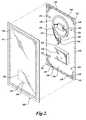
- FIG. 2is an exploded front isometric view of the mirror/media display device assembly of FIG. 1 ;
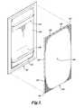
- FIG. 3is an exploded rear isometric view of the mirror/media display device assembly of FIG. 1 ;
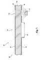
- FIG. 4is a cross-sectional view of the mirror/media display device assembly of FIG. 1 constructed in accordance with a first embodiment of the present disclosure
- FIG. 5is a cross-sectional view of a mirror/media display device assembly constructed in accordance with a second embodiment of the present disclosure
- FIG. 6is a cross-sectional view of a mirror/media display device assembly constructed in accordance with a third embodiment of the present disclosure
- FIG. 7is a cross-sectional view of a mirror/media display device assembly constructed in accordance with a fourth embodiment of the present disclosure.
- FIG. 8is an isometric view of a previously known media display device with an external power adapter.
- FIG. 9is an isometric view of the media display device of a mirror/media display device assembly, showing the media display device having power adapter constructed in accordance with one embodiment of the present disclosure.
- a mirror/media display device assembly 100 constructed in accordance with one embodiment of the present disclosuremay be best understood by referring to FIGS. 1-4 .
- the mirror/media display device assembly 100includes a framed or frameless mirror platform 102 attached to a chassis 140 .
- the mirror platform 102includes a substantially reflective surface 132 , one or more translucent back lit portions 130 , and a media display device viewing portion 128 , through which a media display device 120 located behind the mirror platform 102 can be viewed.
- the chassis 140includes edge sections 142 arranged to form a perimeter (i.e., periphery) of the chassis 140 .
- the edge sections 142include one or more apertures 148 .
- the chassis 140is described as including apertures 148 , it should be apparent that chassis 140 without apertures 148 are also within the scope of the present disclosure.
- Light emanating from the assembly 100is illustrated schematically by reference numeral 134 .
- the one or more back lit portions 130 located on the mirror platform 102have substantially no reflectivity (e.g., frosted glass, acid etched glass or clear glass). These back lit portions 130 are translucent, allowing light emitted from one or more light sources 122 disposed within the mirror/media display device assembly 100 to pass through the mirror platform 102 .
- the number, configuration, and arrangement of back lit portions 130can be varied to achieve different lighting effects.
- the back lit portion 130is configured as a single, continuous portion extending around the perimeter of the mirror platform 102 .
- each side of the chassisincludes a single aperture that extends along the length of the side of the chassis.
- the chassisincludes a single aperture that extends along the length of the lower edge of the chassis, illuminating a sink or countertop above which the mirror/media display device assembly 100 is mounted.
- the apertures 148 of the chassis 140can be optionally covered by a transparent or translucent material (e.g., a plastic strip).
- a transparent or translucent materiale.g., a plastic strip
- the materialcan be colored so that light radiated through the apertures 148 creates a desired visual effect.
- back lightingis provided by radiating light through the back lit portions 130 of the mirror platform 102 .
- the back lit portions 130include translucent areas having substantially no reflectivity or could be partially reflective. The low reflectivity allows light from the light source 122 to pass through the mirror, illuminating the back lit portions 130 of the mirror platform 102 .
- the number and shape of the back lit portions 130can be varied to provide desired visual effects.
- the media display device 120is mounted within the mirror/media display device assembly 100 so that the screen of the media display device 120 aligns with the media display device viewing area 128 of the mirror platform 102 .
- the term “media display device”should be understood to include any media display device suitable for receiving television signals, computer signals, VGA connections, digital signals, etc., and displaying a corresponding image.
- the media display device 120includes a well-known indicator light 136 and infrared sensor 138 .
- the indicator light 136provides a signal indicating whether the media display device is “powered on” or “powered off.”
- the infrared sensor 138provides a remote communication port with the media display device 120 .
- the indicator light 136 and infrared sensor 138are suitably located on a forward face of the media display device housing.
- the infrared sensor 138 and indicator light 136each aligns with a part the mirror platform 102 having little or no reflectivity.
- the reduced reflectivitymakes the indicator light more readily visible from the front side of the mirror platform 102 and also allows the infrared signal from a remote control to pass through the mirror platform 102 .
- the media display device 120is attached to the mirror/media display device assembly 100 by a suitably shaped and configured mounting bracket (not shown).
- the media display device 120can be attached to the mounting bracket with removable fasteners, such as screws and magnets.
- the mounting bracketis open on one side, typically the top or bottom so that it does not interfere with audio/video connections of the media display device 120 .
- One version of the mounting bracketallows the media display device 120 to slide in from the bottom and snap into place without being mechanically fastened.
- an access area(not shown) can be provided through the bottom of the chassis 140 .
- the access areaallows a user to reach up behind the mirror platform 102 and remove the media display device 120 for repair or replacement. In a like manner, the media display device 120 can be easily remounted through the access area.
- the chassis 140includes a central opening 166 sized for a direct connection of an external electrical cable 160 to a terminal block 158 which, in turn, is in electrical communication with an electrical ballast 156 .
- the connection at the terminal block 158is covered with a metal box to provide an isolated electrical connection and thereby eliminate the need for an external electrical box.
- a further opening or openingsare provided to accommodate a power receptacle and audio and video connections.
- the lighting componentscould be plugged into a receptacle.
- the chassis 140is suitably manufactured from a variety of materials including, metal, wood, fiberglass, and various polymers. Polymers and other materials can optionally be transparent or translucent.
- the mirror platform 102includes a rear surface 126 having flanges 152 .
- the flanges 152include slots for receiving hanging pins 154 , which are attached to a the back surface 146 of the chassis 140 (see FIG. 2 ), to removably couple the mirror platform to the chassis 140 .
- the mirror platformcan be coupled to the chassis through any of a variety of suitable methods, including temporary fasteners, permanent fasteners, adhesives, etc.
- FIG. 4illustrates a mirror/media display device assembly 100 having a mirror platform 400 constructed in accordance with one embodiment of the present disclosure.
- the mirror platform 400includes a glass layer 404 , a reflective layer 406 , and backing layer 408 .
- a mirror platform 400is referred to as a “transmissive mirror.”
- the transmissive mirrorincludes a front surface 424 and a rear surface 426 .
- the reflective layer 406provides a partial reflectivity to the transmissive mirror and is suitably formed by a reflective film, a sputter coating, or any other type of suitable reflective material.
- the reflective layer 406is both reflective and transmissive. While the reflective layer 406 is shown on the rear surface 426 of the transmissive mirror, it can also be located on the front surface 424 or both the front and rear surfaces 424 and 426 of the transmissive mirror.
- the transmissive mirroris partially transmissive, preferably having a transmissivity of about 50%, although mirrors having transmissivity between about 30% and about 70% are within the scope of this embodiment.
- the backing layer 408is selectively disposed on the rear surface 426 of the transmissive mirror.
- the backing layer 408increases the reflectivity of the mirror platform 400 in areas to which it is applied. Because of the increased reflectivity, these areas provide a better reflection, which is closer to that of a standard mirror, than do the portions of the transmissive mirror to which the reflective backing is not applied.
- the backing layer 408is not applied to the transmissive mirror in the media display device viewing area 428 .
- the media display device viewing area 428has some reflectivity due to the reflectivity of the transmissive mirror
- the media display device viewing area 428has less reflectivity than the areas of the transmissive mirror to which the backing layer 408 has been applied.
- the reduced reflectivity in the media display device viewing area 428causes less glare and consequently results in a clearer view of the images displayed on the media display device.
- the substantially black media display device screen located behind the media display device viewing area 428will change the light ratio between the front and back of the mirror; thereby, allowing transmissive mirror to operate at its maximum reflectivity. Accordingly, the reflection from the media display device viewing area 428 will more closely match that of the rest of the transmissive mirror, causing the media display device viewing area 428 to blend in with the rest of the transmissive mirror.
- the backing layer 408is suitably formed from a reflective film, sputter coating, silvering, or any other material that enhances reflectivity when applied to a surface 426 .
- a variety of suitable techniquescan be used to selectively apply the reflective backing, including masking areas in which the reflective backing is not to be applied, using computer controlled applicators, or applying the backing to the entire transmissive mirror and then selectively removing it.
- the transmissive mirroralso includes first and second back lit portions 430 and 432 .
- the back lit portions 430 and 432are suitably formed on the transmissive mirror by different methods. As previously described, the back lit portions are at least partially translucent, having lower reflectivity and/or higher transmissivity than the rest of the transmissive mirror. Accordingly, back lit portions 430 , 432 can be formed by decreasing the reflectivity of the back lit portion relative to the rest of the transmissive mirror.
- a first back lit portion 430 formed on the mirror platform 400is similar in construction to the media display device viewing area 428 .
- the first back lit portion 430is defined by an area where the backing layer 408 is not present.
- the first back lit portion 430can be formed by the selective application of the backing layer 408 , during which the backing layer 408 is not applied to the first back lit portion, or the selective removal of the reflective backing after it has been applied to the first back lit portion.
- the backing layer 408may be removed from the first back lit portion by any suitable method, including acid etching, and an acid dip prior to which areas of the reflective backing that are to remain are masked.
- a film simulating a “frosted” effectmay be placed on the backside of reflective layer 406 .
- a second back lit portion 432is provided on the mirror platform 400 .
- the second back lit portion 432is similar to the first back lit portion 430 except that, in addition to the backing layer 408 , some or all of the reflective layer 406 of the transmissive mirror is also removed in the area of the second back lit portion 432 . Consequently, when light from the light source 422 is irradiated onto the rear surface 426 of the mirror platform 400 at a second back lit portion 432 , at least some of the light is transmitted through the transmissive mirror to illuminate the front surface of the mirror platform 400 at the second back lit portion 432 .
- the reflective layer 406 of the transmissive mirrorhas been removed, a greater percentage of light from the light source 422 will pass through the second back lit portion 432 than will pass through the first back lit portion 430 .
- any suitable number of back lit portionssuch as three, four, five, six, etc., can be formed on the platform assembly 400 and, therefore, are also within the scope of the present disclosure.
- the reflective layer 406 and the backing layer 408may be removed from the second back lit portion by any suitable method, including sand blasting, acid etching, and an acid dip. Areas of the reflective layer 406 and backing layer 408 that are to remain are masked prior to removal treatment. Sandblasting, is particularly effective for providing a “frosted” effect in the back lit portion 432 . A protective coating may be applied to the sand blasted areas of the glass to allow the sand blasted areas to be more easily cleaned and prohibit staining from finger prints, dirt, etc. This could occur for sand blasting on the front or back surface of the mirror.
- the resist used to mask off the mirror for sandblastingmay also be used as a safety back material.
- the resistis removed from the mirror after it has been sand blasted. In this case the resist would be left on and act as a safety backing.
- the resistmay be laid on the back of the mirror and cut by a laser or other method or may be plotted and then placed on the back of the mirror.
- Areas of the backing layer 408 and/or the reflective layer 406 of the transmissive mirrorcan also be selectively removed to provide areas of lower reflectivity to accommodate an indicator light 136 or an infrared sensor 138 (see FIG. 1 ).
- FIG. 5illustrates a mirror/media display device assembly 100 having a mirror platform 500 constructed in accordance with a second embodiment of the present disclosure.
- the mirror platform 500is substantially identical in construction, material and operation as the mirror platform 400 described above with the following exceptions.
- the mirror platform 500includes a glass layer 504 and a backing layer 506 , and also includes a front surface 524 and a rear surface 526 .
- the rear surface 526 of the backing layer 506is typically painted with a protective paint.
- the mirror platform 500is referred to as a “standard mirror.”
- the standard mirrorprovides substantially no transmissivity, while reflecting almost all incident light.
- Commercially available standard mirrorswhich are suitable for use with this embodiment, typically have a reflectivity of about 98%, which provides a very good reflection in the mirror portion of the mirror platform 500 .
- a mirror having a lower reflectivity than a standard mirrorcan be used within the scope of this embodiment.
- a standard mirrorusually has a backing layer 506 located on the rear surface 526 of the mirror, a standard mirror with a reflective material located on the front surface 524 of the mirror can also be used.
- the mirror platform 500also includes a media display device viewing area 528 .
- the media display device viewing area 528is formed by an area that has been made non-reflective by selectively removing the backing layer 506 from the glass layer 504 .
- a preferred method for selectively removing the reflective backingincludes isolating the area by applying tape, printed ink or a similar item to the back of the standard mirror around the area from which the reflective backing is to be removed. Paint remover or a similar solvent is then applied to the rear surface 5286 , and paint is removed with a scraping device such as a razor blade.
- the areais then washed with water or other suitable material to remove the paint and expose the backing layer 506 of the standard mirror.
- a sharp instrumentis used to define the outer perimeter of the media display device viewing area 528 , and an etching solution, such as Ferric chloride (FEC13), printed circuit board etching solution, or a similar material is applied to the exposed backing layer 506 .
- an etching solutionsuch as Ferric chloride (FEC13), printed circuit board etching solution, or a similar material is applied to the exposed backing layer 506 .
- FEC13Ferric chloride
- the solutionis wiped away, which removes the backing layer 506 , leaving only the glass layer 504 .
- the media display device viewing area 528is masked off on a piece of glass, and backing layer 506 is added to the glass layer 504 .
- the media display device viewing area 528is close to 100% transmissive. Accordingly, when the media display device 520 is aligned with the media display device viewing area 528 , the light from the media display device is transmitted through the glass layer 504 with minimal loss, making the images on the media display device screen readily visible from the front of the mirror platform 500 .
- the backing layer 506can also be removed from locations on the mirror platform 500 corresponding to an indicator light 136 or an infrared sensor 138 (see FIG. 1 ).
- a back lit portion 530 of the mirror platform 500allows light from a light source 522 located behind the rear surface 526 to pass through to illuminate a portion of the front surface 524 of the mirror platform 500 .
- Back lit portions 530are at least partially translucent and can be formed using the same processes employed to create the media display device viewing area 528 . Alternately, sand blasting, chemical etching, dipping in a chemical bath, or treatment in any other manner previously disclosed, are also within the scope of the present disclosure to form back lit portions.
- a clear backing filmmay be added to the back side of the mirror to create safety mirror while at the same time allowing for light and display image to shine through.
- FIG. 6illustrates a mirror/media display device assembly 100 having a mirror platform 600 constructed in accordance with yet another embodiment of the present disclosure.
- the mirror platform 600is substantially identical in construction, material and operation as the mirror platforms described above with the following exceptions.
- the mirror platform 600includes a glass layer 604 and a reflective layer 606 .
- the reflective layer 606is selectively removed from the rear surface 626 of the mirror platform 600 to form a media display device viewing area 628 .
- Light emitted from the media display device 620passes through the front surface 624 of the glass layer 604 , making the images from the media display device 620 visible from the front surface of the mirror platform 600 .
- the mirror platform 600also includes a polarized film 632 .
- the polarized film 632is disposed between the media display device 620 and the glass layer 604 .
- the media display device 620emits polarized light, approximately 100% of which is selectively allowed to pass through the polarized film 632 .
- suitable media display deviceis an LCD media display device, which is known to emit polarized light. The light passes through the polarized film 632 and the glass layer 604 , allowing the media display device images to be viewed from the front of the mirror platform 600 .
- the polarized film 632is reflective when the media display device is off, resulting in an increased reflectivity in the media display device viewing area. As a result, the media display device viewing area 628 of the mirror platform 600 blends into the surrounding mirror, making it less noticeable when the media display device is in an “off” state.
- the polarized film 632is preferably attached directly to the glass layer 604 of the mirror platform 600 . Attaching the polarized film 632 in this manner places the film in substantially the same plane as the backing layer 606 , thereby minimizing the difference between the appearance of the standard mirror portion and the media display device viewing portion. Alternately, the polarized film 632 can be mounted on a separate piece of glass, which is then disposed between the media display device 620 and the glass layer 604 . As an alternative to the polarized film 632 , a transmissive mirror may be used.
- the mirror platform 600may also include one or more back lit portions 630 .
- the back lit portions 630are at least partially translucent and can be formed using any previously disclosed method suitable for forming the back lit portions 530 .
- FIG. 7illustrates a mirror/media display device assembly 100 having a mirror platform 700 constructed in accordance with still yet another embodiment of the present disclosure.
- the mirror platform [ 700 ]is substantially identical in construction, material and operation as the mirror platforms described above with the following exceptions.
- the mirror platform 700includes a glass layer 704 and a reflective layer 706 .
- the mirror platform 700also includes a front surface 724 and a rear surface 726 .
- the reflective layer 706which is not completely opaque, is affixed to one or both sides of the glass layer 704 .
- the reflective layer 706gives the mirror platform 700 a high reflectivity.
- the reflective coatingimparts a low transmissivity, typically in the range of about 10% to about 25%.
- the media display device 720is a high brightness media display device, having a brightness in the range of about 500 to about 2000 nits.
- the low transmissivity of the mirror platform 700prevents transmission of about 75% to 90% of the light emitted from the media display device 720 .
- the remaining 10% to 25% of the emitted lightpasses through the glass layer 704 and can be viewed from the front of the mirror platform 700 .
- Standard media display devicestypically operate in a range of about 300 to 500 nits of brightness. Accordingly the brightness of the media display device 720 and the transmissivity of the mirror platform 700 can be chosen to provide a desired image brightness.
- a transparent mirror with a transmissivity of [25] %can be paired with a media display device having about 2000 nits of brightness, resulting in an image viewed from the front side of the mirror platform 700 with a brightness of about 500 nits.
- the operating environmentcan also influence the selection of the transmissivity of the transparent mirror and the brightness of the media display device.
- the quality of the reflection from the mirror platform 700can be improved by applying a backing layer 740 to the rear surface 726 in locations other than the media display device viewing area 728 or a back lit portion 730 .
- the backing layer 740is preferably black, and may also act as a safety backing, and reduces the transmissivity of the mirror, thereby improving the quality of the reflection in those areas of the mirror to which the black backing is applied.
- the media display device 720has a generally black screen when turned off, increasing the reflectiveness of the mirror in the media display device viewing area 728 . As a result, the quality of the reflection in the media display device viewing area is improved when the media display device is in a “off” state.
- the mirror platform 700may also include one or more back lit portions 730 .
- the back lit portion 730is formed by selectively removing the reflective layer 706 from the glass layer 704 .
- Sandblastingis preferably used, but any suitable method can be used, including chemical etching, chemical bath, or abrasion.
- the back lit portions 730are at least partially translucent and allow more light to pass through than do the portions of the mirror platform 700 from which the reflective coating has not been selectively removed. As a result, light from a light source 722 located behind the mirror platform 700 passes through the glass layer 704 , illuminating the back lit portion 730 .
- the media display device 120has a thin profile, such as about one inch or less. Such a thin profile minimizes the distance that the mirror/media display device assembly 100 extends from a wall to which it is mounted. In general, the overall thickness of the mirror/media display device assembly 100 is less than about two and one-quarter inches and, in some embodiments, as thin as one and one-quarter inches, or less.
- the media display device 120is configured so that audio and visual connection components (such as the audio wire, RF cable, S-video cable, power cable) come directly out the top or in some cases, the bottom of the housing of the media display device 120 rather than from the rear of the media display device 120 .
- the disclosed media display devicehas an integral, low-profile power adapter 900 that fits within the thin (e.g., one inch) media display device housing.
- FIG. 8illustrates an integral, low-profile power adapter 900 constructed in accordance with one embodiment of the present disclosure.
- the power adapter 900is contained in the housing of a media display device 120 .
- a suitable low-profile power adapteris Model No. TR36A -12, manufactured by Cincon Electronics Co. LTD. Making the low-profile power adapter 900 integral to the media display device also simplifies assembly by reducing the number of parts to be assembled.
Landscapes
- Physics & Mathematics (AREA)
- Engineering & Computer Science (AREA)
- General Physics & Mathematics (AREA)
- Theoretical Computer Science (AREA)
- Chemical & Material Sciences (AREA)
- Optics & Photonics (AREA)
- Materials Engineering (AREA)
- Organic Chemistry (AREA)
- Mechanical Engineering (AREA)
- Chemical Kinetics & Catalysis (AREA)
- General Chemical & Material Sciences (AREA)
- Accounting & Taxation (AREA)
- Marketing (AREA)
- Business, Economics & Management (AREA)
- Metallurgy (AREA)
- Manufacturing & Machinery (AREA)
- Life Sciences & Earth Sciences (AREA)
- Geochemistry & Mineralogy (AREA)
- Devices For Indicating Variable Information By Combining Individual Elements (AREA)
- Illuminated Signs And Luminous Advertising (AREA)
- Mirrors, Picture Frames, Photograph Stands, And Related Fastening Devices (AREA)
- Optical Elements Other Than Lenses (AREA)
Abstract
Description
Claims (16)
Priority Applications (15)
| Application Number | Priority Date | Filing Date | Title |
|---|---|---|---|
| US11/563,119US8099247B2 (en) | 2005-11-23 | 2006-11-24 | Back lit mirror with media display device |
| US12/047,243US7805260B2 (en) | 2005-11-23 | 2008-03-12 | Mirror assembly |
| US12/383,624US8910402B2 (en) | 2005-11-23 | 2009-03-27 | Medicine cabinet assembly |
| US12/425,186US7853414B2 (en) | 2005-11-23 | 2009-04-16 | Mounting structure for a mirror assembly |
| US12/928,524US9105202B2 (en) | 2005-11-23 | 2010-12-13 | Backlight illumination in a mirror |
| US13/374,430US8880360B2 (en) | 2005-11-23 | 2011-12-28 | Mirror with media display device |
| US14/530,820US9845537B2 (en) | 2005-11-23 | 2014-11-02 | Mirror and media display device assembly apparatuses and methods |
| US14/531,138US10106896B2 (en) | 2005-11-23 | 2014-11-03 | Mirror with media display device viewing area |
| US14/531,104US20150205110A1 (en) | 2005-11-23 | 2014-11-03 | Low profile mirror and media display device assembly |
| US14/822,860US20160070085A1 (en) | 2005-11-23 | 2015-08-10 | Mounting structure for a mirror assembly |
| US15/700,187US9921390B1 (en) | 2005-11-23 | 2017-09-11 | Mounting structure for a mirror assembly |
| US15/700,191US9933595B1 (en) | 2005-11-23 | 2017-09-11 | Mounting structure for a mirror assembly |
| US15/943,664US10502928B1 (en) | 2005-11-23 | 2018-04-02 | Mounting structure for a mirror assembly |
| US16/120,197US10968523B1 (en) | 2005-11-23 | 2018-08-31 | Vanishing viewing windows apparatuses and methods |
| US17/221,808US11859293B1 (en) | 2005-11-23 | 2021-04-04 | Vanishing viewing windows apparatuses and methods |
Applications Claiming Priority (4)
| Application Number | Priority Date | Filing Date | Title |
|---|---|---|---|
| US73939905P | 2005-11-23 | 2005-11-23 | |
| US73915605P | 2005-11-23 | 2005-11-23 | |
| US79420906P | 2006-04-21 | 2006-04-21 | |
| US11/563,119US8099247B2 (en) | 2005-11-23 | 2006-11-24 | Back lit mirror with media display device |
Related Child Applications (4)
| Application Number | Title | Priority Date | Filing Date |
|---|---|---|---|
| US12047243Continuation-In-Part | 2003-03-12 | ||
| US12/047,243Continuation-In-PartUS7805260B2 (en) | 2005-11-23 | 2008-03-12 | Mirror assembly |
| US12/383,624Continuation-In-PartUS8910402B2 (en) | 2005-11-23 | 2009-03-27 | Medicine cabinet assembly |
| US13/374,430ContinuationUS8880360B2 (en) | 2005-11-23 | 2011-12-28 | Mirror with media display device |
Publications (2)
| Publication Number | Publication Date |
|---|---|
| US20070159316A1 US20070159316A1 (en) | 2007-07-12 |
| US8099247B2true US8099247B2 (en) | 2012-01-17 |
Family
ID=38068064
Family Applications (7)
| Application Number | Title | Priority Date | Filing Date |
|---|---|---|---|
| US11/563,119Active - Reinstated2028-10-10US8099247B2 (en) | 2005-11-23 | 2006-11-24 | Back lit mirror with media display device |
| US13/374,430ActiveUS8880360B2 (en) | 2005-11-23 | 2011-12-28 | Mirror with media display device |
| US14/530,820ActiveUS9845537B2 (en) | 2005-11-23 | 2014-11-02 | Mirror and media display device assembly apparatuses and methods |
| US14/531,138ActiveUS10106896B2 (en) | 2005-11-23 | 2014-11-03 | Mirror with media display device viewing area |
| US14/531,104AbandonedUS20150205110A1 (en) | 2005-11-23 | 2014-11-03 | Low profile mirror and media display device assembly |
| US16/120,197ActiveUS10968523B1 (en) | 2005-11-23 | 2018-08-31 | Vanishing viewing windows apparatuses and methods |
| US17/221,808ActiveUS11859293B1 (en) | 2005-11-23 | 2021-04-04 | Vanishing viewing windows apparatuses and methods |
Family Applications After (6)
| Application Number | Title | Priority Date | Filing Date |
|---|---|---|---|
| US13/374,430ActiveUS8880360B2 (en) | 2005-11-23 | 2011-12-28 | Mirror with media display device |
| US14/530,820ActiveUS9845537B2 (en) | 2005-11-23 | 2014-11-02 | Mirror and media display device assembly apparatuses and methods |
| US14/531,138ActiveUS10106896B2 (en) | 2005-11-23 | 2014-11-03 | Mirror with media display device viewing area |
| US14/531,104AbandonedUS20150205110A1 (en) | 2005-11-23 | 2014-11-03 | Low profile mirror and media display device assembly |
| US16/120,197ActiveUS10968523B1 (en) | 2005-11-23 | 2018-08-31 | Vanishing viewing windows apparatuses and methods |
| US17/221,808ActiveUS11859293B1 (en) | 2005-11-23 | 2021-04-04 | Vanishing viewing windows apparatuses and methods |
Country Status (2)
| Country | Link |
|---|---|
| US (7) | US8099247B2 (en) |
| WO (1) | WO2007062409A2 (en) |
Cited By (22)
| Publication number | Priority date | Publication date | Assignee | Title |
|---|---|---|---|---|
| US20120033312A1 (en)* | 2010-05-18 | 2012-02-09 | Electric Mirror, Llc | Apparatuses and methods for changing the appearance of an object mounted behind a mirror |
| US20140104830A1 (en)* | 2012-10-15 | 2014-04-17 | American Dj Supply, Inc. | Lighting apparatus with a mounting system for lighting accessories |
| US20150205110A1 (en)* | 2005-11-23 | 2015-07-23 | Electric Mirror, Llc | Low profile mirror and media display device assembly |
| US20160315288A1 (en)* | 2015-04-24 | 2016-10-27 | Samsung Display Co., Ltd. | Display device |
| US9765958B2 (en) | 2015-05-21 | 2017-09-19 | Séura, Inc. | Illuminated mirror |
| US10448762B2 (en) | 2017-09-15 | 2019-10-22 | Kohler Co. | Mirror |
| US10663938B2 (en) | 2017-09-15 | 2020-05-26 | Kohler Co. | Power operation of intelligent devices |
| US10702043B2 (en) | 2015-03-06 | 2020-07-07 | Simplehuman, Llc | Mirror system having a mirror, light source and software module or app that communicates instructions to adjust lighting based on a sensed condition |
| US10746394B2 (en) | 2012-03-08 | 2020-08-18 | Simplehuman, Llc | Vanity mirror |
| US10869537B2 (en) | 2017-03-17 | 2020-12-22 | Simplehuman, Llc | Vanity mirror |
| US10887125B2 (en) | 2017-09-15 | 2021-01-05 | Kohler Co. | Bathroom speaker |
| US11026497B2 (en) | 2018-02-14 | 2021-06-08 | Simplehuman, Llc | Compact mirror |
| USD927863S1 (en) | 2019-05-02 | 2021-08-17 | Simplehuman, Llc | Vanity mirror cover |
| US11093554B2 (en) | 2017-09-15 | 2021-08-17 | Kohler Co. | Feedback for water consuming appliance |
| US11099540B2 (en) | 2017-09-15 | 2021-08-24 | Kohler Co. | User identity in household appliances |
| US11262790B1 (en) | 2020-02-03 | 2022-03-01 | Delta Tech Llc | Low-profile smart mirror with backside mount |
| US11496887B1 (en)* | 2010-05-18 | 2022-11-08 | Electric Mirror, Llc | Apparatuses and methods for streaming audio and video |
| US11640042B2 (en) | 2019-03-01 | 2023-05-02 | Simplehuman, Llc | Vanity mirror |
| USD990174S1 (en) | 2019-03-01 | 2023-06-27 | Simplehuman, Llc | Vanity mirror |
| US11708031B2 (en) | 2018-03-22 | 2023-07-25 | Simplehuman, Llc | Voice-activated vanity mirror |
| US12225999B2 (en) | 2018-09-19 | 2025-02-18 | Simplehuman, Llc | Vanity mirror |
| US12396577B2 (en) | 2023-03-03 | 2025-08-26 | Simplehuman, Llc | Vanity mirror with hidden sensor |
Families Citing this family (43)
| Publication number | Priority date | Publication date | Assignee | Title |
|---|---|---|---|---|
| US7805260B2 (en)* | 2005-11-23 | 2010-09-28 | Electric Mirror, Llc | Mirror assembly |
| US7853414B2 (en)* | 2005-11-23 | 2010-12-14 | Electric Mirror, Llc | Mounting structure for a mirror assembly |
| RU2438157C2 (en) | 2007-04-20 | 2011-12-27 | Коулер Ко. | User interface for controlling bathroom plumbing fixture |
| US7600886B1 (en) | 2008-04-11 | 2009-10-13 | Cornerstone Lighting, Llc | Backlit mirror assembly and method for use |
| US20100053474A1 (en)* | 2008-08-31 | 2010-03-04 | Hiromi Kamei | Systems and methods for eliminating laser light source scintillation in a projection television |
| US20100058628A1 (en)* | 2008-09-05 | 2010-03-11 | Brian P. Reid | Frame Assembly for Displaying Indicia and Reflecting An Image |
| US8194507B2 (en)* | 2008-09-08 | 2012-06-05 | Brookstone Purchasing, Inc. | Hidden display and clock audio apparatus including same |
| US20100103545A1 (en)* | 2008-10-28 | 2010-04-29 | Ford Global Technologies, Llc | Rear view mirror |
| CN102300489A (en)* | 2009-01-30 | 2011-12-28 | 皇家飞利浦电子股份有限公司 | Mirror unit comprising a mirror surface and a lighting unit |
| WO2010100609A1 (en)* | 2009-03-06 | 2010-09-10 | Koninklijke Philips Electronics N.V. | Method for converting input image data into output image data, image conversion unit for converting input image data into output image data, image processing apparatus, display device |
| US9747417B2 (en)* | 2013-11-14 | 2017-08-29 | Mores, Inc. | Method and apparatus for enhanced personal care |
| US9838508B2 (en)* | 2013-11-14 | 2017-12-05 | Mores, Inc. | Method and apparatus for enhanced personal care with interactive diary function |
| US20180316781A1 (en)* | 2013-11-14 | 2018-11-01 | Mores, Inc. | System for remote noninvasive contactless assessment and prediction of body organ health |
| US20110056102A1 (en)* | 2009-09-08 | 2011-03-10 | Luxury Tech Holdings, LLC | Frame assembly for displaying indicia and reflecting an image |
| US8074386B2 (en)* | 2009-11-12 | 2011-12-13 | Marantz Jacob J | Integrated mirror and graphics display system |
| ITBS20100073A1 (en)* | 2010-04-12 | 2011-10-13 | Flos Spa | BACKLIGHT MIRROR |
| US20120081881A1 (en)* | 2010-05-18 | 2012-04-05 | Electric Mirror, Llc | Medicine cabinet doors |
| US9611990B2 (en)* | 2011-05-30 | 2017-04-04 | Mary L. Ellis | Light bars |
| BE1019938A3 (en)* | 2012-03-09 | 2013-02-05 | Tait Technologies Bvba | SYSTEM FOR VIDEO VIEWING. |
| US20140237783A1 (en)* | 2013-02-28 | 2014-08-28 | Co2Nexus, Inc. | Application and activation of durable water repellant using a densified fluid |
| US9307849B2 (en)* | 2013-08-05 | 2016-04-12 | Electric Mirror, Llc | Modular mirror chassis apparatuses and methods |
| US10998092B2 (en)* | 2013-11-14 | 2021-05-04 | Mores, Inc. | Dispenser apparatus |
| US10998099B2 (en)* | 2013-11-14 | 2021-05-04 | Mores, Inc. | Health band apparatus |
| WO2016170997A1 (en)* | 2015-04-21 | 2016-10-27 | 旭硝子株式会社 | Mirror with display device |
| KR102058456B1 (en) | 2015-08-31 | 2019-12-23 | 삼성전자주식회사 | Display apparatus and appliances having the same |
| USD941815S1 (en)* | 2015-09-03 | 2022-01-25 | Sony Corporation | Display |
| DE102017105156A1 (en)* | 2017-03-10 | 2018-09-13 | Jokey Plastik Sohland Gmbh | Bathroom mirror device with electronics module |
| US10670258B2 (en) | 2017-05-05 | 2020-06-02 | Hubbell Incorporated | Illuminated mirror |
| WO2018216545A1 (en)* | 2017-05-22 | 2018-11-29 | シャープ株式会社 | Display device |
| CN107300802B (en)* | 2017-08-01 | 2020-09-01 | 深圳市华星光电技术有限公司 | Mirror display device |
| USD1008266S1 (en)* | 2018-05-15 | 2023-12-19 | Guangzhou Shiyuan Electronics Co., Ltd. | Smart interactive display board |
| CN109363453B (en)* | 2018-12-26 | 2024-11-22 | 佛山市南海豪迪卫浴有限公司 | A smart bath mirror |
| CN211186672U (en)* | 2019-11-29 | 2020-08-07 | 宁波港普光电科技有限公司 | L ED lamp mirror |
| USD1087622S1 (en)* | 2020-01-25 | 2025-08-12 | Electric Mirror, Llc | Round mirror with frame |
| IT202000008731A1 (en) | 2020-04-23 | 2021-10-23 | Vanita & Casa S R L | BACKLIT MIRROR |
| DE102020003459A1 (en)* | 2020-06-09 | 2021-12-09 | Stickerei Keinath GmbH | Improved Method of Making an Image / Icon Display Device |
| JP7177803B2 (en)* | 2020-07-08 | 2022-11-24 | シャープ株式会社 | Display device |
| RU206429U1 (en)* | 2021-06-21 | 2021-09-13 | Общество с ограниченной ответственностью "СтендАп Инновации" | Interactive speech therapy smart mirror |
| RU206431U1 (en)* | 2021-07-01 | 2021-09-13 | Общество с ограниченной ответственностью "СтендАп Инновации" | Interactive speech therapy smart mirror |
| USD1091147S1 (en)* | 2021-07-26 | 2025-09-02 | Electric Mirror, Llc | Oval mirror with frame |
| WO2023010145A1 (en) | 2021-08-06 | 2023-02-09 | Daniel Schrott | Display device |
| USD1088575S1 (en)* | 2022-01-21 | 2025-08-19 | Prosperous(Ningbo)Lighting Appliance Co., Ltd | Mirror |
| CN117580205A (en)* | 2023-12-07 | 2024-02-20 | 东莞莱姆森科技建材有限公司 | An ultra-thin LED light mirror and mirror cabinet |
Citations (42)
| Publication number | Priority date | Publication date | Assignee | Title |
|---|---|---|---|---|
| US3757103A (en) | 1971-05-17 | 1973-09-04 | Clairol Inc | Make up mirror |
| US4003271A (en) | 1975-03-14 | 1977-01-18 | Keeler Brass Company | Mirror assembly |
| US4009947A (en) | 1973-02-15 | 1977-03-01 | Canon Kabushiki Kaisha | Reflecting mirror |
| US4202607A (en) | 1975-03-17 | 1980-05-13 | Sharp Kabushiki Kaisha | Mirror with information display |
| USD264414S (en) | 1980-04-17 | 1982-05-18 | Allibert S.A. | Illuminated mirror |
| US4361981A (en) | 1981-06-01 | 1982-12-07 | Arco Industries Ltd. | Toy make-up center |
| US4635994A (en) | 1984-02-10 | 1987-01-13 | Gebr. Happich Gmbh | Sun visor, particularly for automotive vehicles, with reversible mirror |
| USD290007S (en) | 1984-03-09 | 1987-05-26 | Matsushita Electric Industrial Co., Ltd. | Combined clock, radio and television receiver |
| US4733229A (en)* | 1984-01-24 | 1988-03-22 | Whitehead Frank R | Highlighting gray scale video display terminal |
| USD299491S (en) | 1986-04-30 | 1989-01-24 | Road Runner Co., Ltd. | Combined vehicle rear view mirror and television |
| US4922384A (en) | 1989-06-08 | 1990-05-01 | Mechtronics Corporation | Illuminated display with half-silvered mirrors and discrete refractor plates |
| USD311820S (en) | 1987-07-31 | 1990-11-06 | Glucksman Dov Z | Illuminated picture frame |
| US5061004A (en) | 1990-03-07 | 1991-10-29 | Gebr. Happich Gmbh | Vehicle sun visor with reversible mirror |
| US5210967A (en) | 1990-12-31 | 1993-05-18 | Brown William D | Hidden display mirror |
| US5575552A (en) | 1994-12-09 | 1996-11-19 | United Technologies Automotive Systems, Inc. | Lighted mirror apparatus |
| US5592240A (en)* | 1994-06-22 | 1997-01-07 | Kabushiki Kaisha Roshiba | Digital convergence apparatus |
| US5668675A (en) | 1995-01-18 | 1997-09-16 | Fredricks; Ronald J. | Opto-electronic aid for alignment of exterior vehicle mirrors to minimize blind spot effects |
| USD405473S (en) | 1997-08-14 | 1999-02-09 | Si Diamond Technology, Inc. | Liquid crystal display |
| US5997149A (en) | 1998-03-31 | 1999-12-07 | Manica Taiwan, Inc. | Reversible backlit personal grooming mirror |
| USD433573S (en) | 1999-04-19 | 2000-11-14 | Societe Piere-Yves Rochon | Lighted mirror |
| US6172613B1 (en) | 1998-02-18 | 2001-01-09 | Donnelly Corporation | Rearview mirror assembly incorporating vehicle information display |
| US20010038505A1 (en) | 1996-05-17 | 2001-11-08 | Takehiko Yamashita | Reflecting mirror and film and television receiver |
| US20020015226A1 (en)* | 2000-06-23 | 2002-02-07 | Oliver Rottcher | Mirror having a portion in the form of an information provider |
| US20020196333A1 (en) | 2001-06-21 | 2002-12-26 | Gorischek Ignaz M. | Mirror and image display system |
| US20030030063A1 (en) | 2001-07-27 | 2003-02-13 | Krzysztof Sosniak | Mixed color leds for auto vanity mirrors and other applications where color differentiation is critical |
| US6567060B1 (en)* | 1997-10-16 | 2003-05-20 | Citizen Watch Co., Ltd. | Liquid display |
| US6709114B1 (en)* | 2000-01-27 | 2004-03-23 | Thomson Licensing S.A. | Spherical mounting system for three axis adjustment of light projector assembly in a projection television |
| USD492127S1 (en) | 2002-11-07 | 2004-06-29 | Marketing Light Export, S.A. | Lighted mirror |
| US6833880B1 (en)* | 2001-07-02 | 2004-12-21 | Mitsubishi Digital Electronics America, Inc. | Bracket for CRT |
| US6921174B1 (en)* | 2000-01-27 | 2005-07-26 | Thomson Licensing, S.A. | Projection television cabinet having a one-piece reference structure |
| US20050168813A1 (en)* | 2004-02-04 | 2005-08-04 | Paul Benning | Projection display screen that is light-reflective responsive to intensity of incident projected light |
| US20050185278A1 (en) | 2002-03-18 | 2005-08-25 | Koninklijke Philips Electronics N.V. | Mirror with built-in display |
| US20050281043A1 (en) | 2003-10-30 | 2005-12-22 | Eisenbraun Kenneth D | Side view mirror with light emitting trim ring |
| US7012727B2 (en)* | 1999-11-24 | 2006-03-14 | Donnelly Corporation | Rearview mirror assembly with utility functions |
| US7067975B2 (en) | 2003-06-10 | 2006-06-27 | Ritdisplay Corporation | Full color display panel with mirror function |
| US20060150462A1 (en)* | 2004-02-20 | 2006-07-13 | Luis Rossi | Decorative cover frame assembly for selectively concealing a flat panel or high definition television display |
| US7088490B2 (en) | 2003-06-18 | 2006-08-08 | Kabushiki Kaisha Tokai-Rika-Denki Seisakusho | Electrochromic mirror having variable reflectivity |
| USD536881S1 (en) | 2005-04-29 | 2007-02-20 | Electric Mirror, L.L.C. | Lighted mirror |
| US20070046841A1 (en)* | 2005-08-26 | 2007-03-01 | Donald Jacobsmeyer | Frame assembly for flat screen television |
| US20070159316A1 (en)* | 2005-11-23 | 2007-07-12 | Electric Mirror, Llc | Back lit mirror with media display device |
| US20070201132A1 (en)* | 2006-02-27 | 2007-08-30 | Cannon Bruce L | Rear projection television optics |
| US7551354B2 (en)* | 2003-02-20 | 2009-06-23 | Koninklijke Philips Electronics N.V. | Mirror with built in display |
Family Cites Families (22)
| Publication number | Priority date | Publication date | Assignee | Title |
|---|---|---|---|---|
| GB1287624A (en)* | 1969-08-21 | 1972-09-06 | Sperry Rand Ltd | Information display systems |
| GB1592158A (en)* | 1976-11-15 | 1981-07-01 | Britax Wingard Ltd | Heated mirrors and methods for making the same |
| US4180931A (en)* | 1977-10-11 | 1980-01-01 | Osch John V | Display device |
| US4882565A (en)* | 1988-03-02 | 1989-11-21 | Donnelly Corporation | Information display for rearview mirrors |
| TW291543B (en)* | 1993-09-28 | 1996-11-21 | Sharp Kk | |
| EP0702494B1 (en)* | 1994-09-19 | 2001-12-05 | Matsushita Electric Industrial Co., Ltd. | Three-dimensional image display apparatus |
| US5793420A (en)* | 1994-10-28 | 1998-08-11 | Schmidt; William P. | Video recording system for vehicle |
| US6891563B2 (en)* | 1996-05-22 | 2005-05-10 | Donnelly Corporation | Vehicular vision system |
| US5825527A (en)* | 1997-04-02 | 1998-10-20 | Gentex Corporation | Information display area on electrochromic mirrors having a third surface metal reflector |
| US6700692B2 (en)* | 1997-04-02 | 2004-03-02 | Gentex Corporation | Electrochromic rearview mirror assembly incorporating a display/signal light |
| US6741788B2 (en)* | 1999-07-01 | 2004-05-25 | Honeywell International Inc | Efficient light distribution system |
| US7009751B2 (en)* | 1999-05-14 | 2006-03-07 | Gentex Corporation | Electrochromic rearview mirror incorporating a third surface partially transmissive reflector |
| US6535318B1 (en)* | 1999-11-12 | 2003-03-18 | Jds Uniphase Corporation | Integrated optoelectronic devices having pop-up mirrors therein and methods of forming and operating same |
| US6390429B1 (en)* | 2000-07-28 | 2002-05-21 | Patrick Brincat | Device for securing an automatic toll-taking transceiver onto a motorcycle |
| US7255451B2 (en)* | 2002-09-20 | 2007-08-14 | Donnelly Corporation | Electro-optic mirror cell |
| AU2003273172A1 (en)* | 2002-05-24 | 2003-12-12 | Magna Donnelly Electronics Naas Limited | Modular rearview mirror assembly |
| WO2004026633A2 (en)* | 2002-09-20 | 2004-04-01 | Donnelly Corporation | Mirror reflective element assembly |
| KR100662780B1 (en)* | 2002-12-18 | 2007-01-02 | 엘지.필립스 엘시디 주식회사 | Liquid crystal display with test pixel and method of manufacturing black matrix using same |
| DE10327180A1 (en)* | 2003-06-17 | 2005-01-13 | Schefenacker Vision Systems Germany Gmbh & Co. Kg | Exterior rearview mirror for vehicles, preferably for motor vehicles |
| US7499117B2 (en)* | 2003-11-14 | 2009-03-03 | Semiconductor Energy Laboratory Co., Ltd. | Liquid crystal display device and manufacturing method thereof |
| US7453686B2 (en)* | 2005-08-29 | 2008-11-18 | Elbex Video Limited | Method and apparatus for attaching display panels onto wall surface |
| US9197274B2 (en)* | 2010-05-04 | 2015-11-24 | Qwest Communications International Inc. | Elastomeric chassis suspension for electronic devices |
- 2006
- 2006-11-24USUS11/563,119patent/US8099247B2/enactiveActive - Reinstated
- 2006-11-24WOPCT/US2006/061238patent/WO2007062409A2/enactiveApplication Filing
- 2011
- 2011-12-28USUS13/374,430patent/US8880360B2/enactiveActive
- 2014
- 2014-11-02USUS14/530,820patent/US9845537B2/enactiveActive
- 2014-11-03USUS14/531,138patent/US10106896B2/enactiveActive
- 2014-11-03USUS14/531,104patent/US20150205110A1/ennot_activeAbandoned
- 2018
- 2018-08-31USUS16/120,197patent/US10968523B1/enactiveActive
- 2021
- 2021-04-04USUS17/221,808patent/US11859293B1/enactiveActive
Patent Citations (43)
| Publication number | Priority date | Publication date | Assignee | Title |
|---|---|---|---|---|
| US3757103A (en) | 1971-05-17 | 1973-09-04 | Clairol Inc | Make up mirror |
| US4009947A (en) | 1973-02-15 | 1977-03-01 | Canon Kabushiki Kaisha | Reflecting mirror |
| US4003271A (en) | 1975-03-14 | 1977-01-18 | Keeler Brass Company | Mirror assembly |
| US4202607A (en) | 1975-03-17 | 1980-05-13 | Sharp Kabushiki Kaisha | Mirror with information display |
| USD264414S (en) | 1980-04-17 | 1982-05-18 | Allibert S.A. | Illuminated mirror |
| US4361981A (en) | 1981-06-01 | 1982-12-07 | Arco Industries Ltd. | Toy make-up center |
| US4733229A (en)* | 1984-01-24 | 1988-03-22 | Whitehead Frank R | Highlighting gray scale video display terminal |
| US4635994A (en) | 1984-02-10 | 1987-01-13 | Gebr. Happich Gmbh | Sun visor, particularly for automotive vehicles, with reversible mirror |
| USD290007S (en) | 1984-03-09 | 1987-05-26 | Matsushita Electric Industrial Co., Ltd. | Combined clock, radio and television receiver |
| USD299491S (en) | 1986-04-30 | 1989-01-24 | Road Runner Co., Ltd. | Combined vehicle rear view mirror and television |
| USD311820S (en) | 1987-07-31 | 1990-11-06 | Glucksman Dov Z | Illuminated picture frame |
| US4922384A (en) | 1989-06-08 | 1990-05-01 | Mechtronics Corporation | Illuminated display with half-silvered mirrors and discrete refractor plates |
| US5061004A (en) | 1990-03-07 | 1991-10-29 | Gebr. Happich Gmbh | Vehicle sun visor with reversible mirror |
| US5210967A (en) | 1990-12-31 | 1993-05-18 | Brown William D | Hidden display mirror |
| US5592240A (en)* | 1994-06-22 | 1997-01-07 | Kabushiki Kaisha Roshiba | Digital convergence apparatus |
| US5575552A (en) | 1994-12-09 | 1996-11-19 | United Technologies Automotive Systems, Inc. | Lighted mirror apparatus |
| US5668675A (en) | 1995-01-18 | 1997-09-16 | Fredricks; Ronald J. | Opto-electronic aid for alignment of exterior vehicle mirrors to minimize blind spot effects |
| US20010038505A1 (en) | 1996-05-17 | 2001-11-08 | Takehiko Yamashita | Reflecting mirror and film and television receiver |
| USD405473S (en) | 1997-08-14 | 1999-02-09 | Si Diamond Technology, Inc. | Liquid crystal display |
| US6567060B1 (en)* | 1997-10-16 | 2003-05-20 | Citizen Watch Co., Ltd. | Liquid display |
| US6172613B1 (en) | 1998-02-18 | 2001-01-09 | Donnelly Corporation | Rearview mirror assembly incorporating vehicle information display |
| US5997149A (en) | 1998-03-31 | 1999-12-07 | Manica Taiwan, Inc. | Reversible backlit personal grooming mirror |
| USD433573S (en) | 1999-04-19 | 2000-11-14 | Societe Piere-Yves Rochon | Lighted mirror |
| US7012727B2 (en)* | 1999-11-24 | 2006-03-14 | Donnelly Corporation | Rearview mirror assembly with utility functions |
| US6709114B1 (en)* | 2000-01-27 | 2004-03-23 | Thomson Licensing S.A. | Spherical mounting system for three axis adjustment of light projector assembly in a projection television |
| US6921174B1 (en)* | 2000-01-27 | 2005-07-26 | Thomson Licensing, S.A. | Projection television cabinet having a one-piece reference structure |
| US20020015226A1 (en)* | 2000-06-23 | 2002-02-07 | Oliver Rottcher | Mirror having a portion in the form of an information provider |
| US20020196333A1 (en) | 2001-06-21 | 2002-12-26 | Gorischek Ignaz M. | Mirror and image display system |
| US6833880B1 (en)* | 2001-07-02 | 2004-12-21 | Mitsubishi Digital Electronics America, Inc. | Bracket for CRT |
| US20030030063A1 (en) | 2001-07-27 | 2003-02-13 | Krzysztof Sosniak | Mixed color leds for auto vanity mirrors and other applications where color differentiation is critical |
| US20050185278A1 (en) | 2002-03-18 | 2005-08-25 | Koninklijke Philips Electronics N.V. | Mirror with built-in display |
| USD492127S1 (en) | 2002-11-07 | 2004-06-29 | Marketing Light Export, S.A. | Lighted mirror |
| US7551354B2 (en)* | 2003-02-20 | 2009-06-23 | Koninklijke Philips Electronics N.V. | Mirror with built in display |
| US7067975B2 (en) | 2003-06-10 | 2006-06-27 | Ritdisplay Corporation | Full color display panel with mirror function |
| US7088490B2 (en) | 2003-06-18 | 2006-08-08 | Kabushiki Kaisha Tokai-Rika-Denki Seisakusho | Electrochromic mirror having variable reflectivity |
| US20050281043A1 (en) | 2003-10-30 | 2005-12-22 | Eisenbraun Kenneth D | Side view mirror with light emitting trim ring |
| US20050168813A1 (en)* | 2004-02-04 | 2005-08-04 | Paul Benning | Projection display screen that is light-reflective responsive to intensity of incident projected light |
| US20060150462A1 (en)* | 2004-02-20 | 2006-07-13 | Luis Rossi | Decorative cover frame assembly for selectively concealing a flat panel or high definition television display |
| US7287737B2 (en)* | 2004-02-20 | 2007-10-30 | Luis Rossi | Decorative cover frame assembly for selectively concealing a flat panel or high definition television display |
| USD536881S1 (en) | 2005-04-29 | 2007-02-20 | Electric Mirror, L.L.C. | Lighted mirror |
| US20070046841A1 (en)* | 2005-08-26 | 2007-03-01 | Donald Jacobsmeyer | Frame assembly for flat screen television |
| US20070159316A1 (en)* | 2005-11-23 | 2007-07-12 | Electric Mirror, Llc | Back lit mirror with media display device |
| US20070201132A1 (en)* | 2006-02-27 | 2007-08-30 | Cannon Bruce L | Rear projection television optics |
Non-Patent Citations (24)
| Title |
|---|
| "Circular Inspiration," ElectricMirror.com, <http://web.archive.org/web/20030828071950/www.electricmirror.com/english/menu/circularinspiration.html>, as early as Aug. 2003. |
| "Eclipse," ElectricMirror.com, , as early as Dec. 2004. |
| "Eclipse," ElectricMirror.com, <http://web.archive.org/web/20041217214430/http://electricmirror.com/index.html>, as early as Dec. 2004. |
| "eFinity," ElectricMirror.com, , as early as Aug. 2003. |
| "eFinity," ElectricMirror.com, <http://web.archive.org/web/20030828072254/www.electricmirror.com/english/menu/efinity.html>, as early as Aug. 2003. |
| "Embrace," ElectricMirror.com, , as early as Dec. 2004. |
| "Embrace," ElectricMirror.com, <http://web.archive.org/web/20041217214430/http://electricmirror.com/index.html>, as early as Dec. 2004. |
| "Embrace," ElectricMirror.com, <http://web.archive.org/web/20060709052632/www.electricmirror.com/embrace.html>, as early as Dec. 2004. |
| "Fusion," ElectricMirror.com, , as early as Aug. 2003. |
| "Fusion," ElectricMirror.com, <http://web.archive.org/web/20030828072111/www.electricmirror.com/english/menu/fusion.html>, as early as Aug. 2003. |
| "Masterpiece," ElectricMirror.com, , as early as Aug. 2003. |
| "Masterpiece," ElectricMirror.com, <http://web.archive.org/web/20030805153142/http://www.electricmirror.com>, as early as Aug. 2003. |
| "Momentum," ElectricMirror.com, , as early as Aug. 2003. |
| "Momentum," ElectricMirror.com, <http://web.archive.org/web/20030805153142/http://www.electricmirror.com>, as early as Aug. 2003. |
| "Radiance," ElectricMirror.com, , as early as Aug. 2003. |
| "Radiance," ElectricMirror.com, <http://web.archive.org/web/20030805153142/http://www.electricmirror.com/>, as early as Aug. 2003. |
| "Steel Pleasure E101," ElectricMirror.com, , as early as Aug. 2003. |
| "Steel Pleasure E101," ElectricMirror.com, <http://web.archive.org/web/20030805153142/http://www.electricmirror.com>, as early as Aug. 2003. |
| "Steel Pleasure E201," ElectricMirror.com, , as early as Aug. 2003. |
| "Steel Pleasure E201," ElectricMirror.com, <http://web.archive.org/web/20030805153142/http://www.electricmirror.com>, as early as Aug. 2003. |
| "Steel Pleasure E301," ElectricMirror.com, , as early as Aug. 2003. |
| "Steel Pleasure E301," ElectricMirror.com, <http://web.archive.org/web/20030805153142/http://www.electricmirror.com>, as early as Aug. 2003. |
| "Trinity," ElectricMirror.com, , as early as Aug. 2003. |
| "Trinity," ElectricMirror.com, <http://web.archive.org/web/20030805153142/http://www.electricmirror.com/>, as early as Aug. 2003. |
Cited By (48)
| Publication number | Priority date | Publication date | Assignee | Title |
|---|---|---|---|---|
| US11859293B1 (en)* | 2005-11-23 | 2024-01-02 | Electric Mirror, Llc | Vanishing viewing windows apparatuses and methods |
| US20150205110A1 (en)* | 2005-11-23 | 2015-07-23 | Electric Mirror, Llc | Low profile mirror and media display device assembly |
| US20120033312A1 (en)* | 2010-05-18 | 2012-02-09 | Electric Mirror, Llc | Apparatuses and methods for changing the appearance of an object mounted behind a mirror |
| US9173509B2 (en)* | 2010-05-18 | 2015-11-03 | Electric Mirror, Llc | Apparatuses and methods for changing the appearance of an object mounted behind a mirror |
| US11496887B1 (en)* | 2010-05-18 | 2022-11-08 | Electric Mirror, Llc | Apparatuses and methods for streaming audio and video |
| US12232217B1 (en)* | 2010-05-18 | 2025-02-18 | Electric Mirror, Llc | Apparatuses and methods for streaming audio and video |
| USD1059051S1 (en) | 2012-03-08 | 2025-01-28 | Simplehuman, Llc | Vanity mirror |
| US11859807B2 (en) | 2012-03-08 | 2024-01-02 | Simplehuman, Llc | Vanity mirror |
| US12313253B2 (en) | 2012-03-08 | 2025-05-27 | Simplehuman, Llc | Vanity mirror |
| US10746394B2 (en) | 2012-03-08 | 2020-08-18 | Simplehuman, Llc | Vanity mirror |
| US11371692B2 (en) | 2012-03-08 | 2022-06-28 | Simplehuman, Llc | Vanity mirror |
| US11566784B2 (en) | 2012-03-08 | 2023-01-31 | Simplehuman, Llc | Vanity mirror |
| USD1009485S1 (en) | 2012-03-08 | 2024-01-02 | Simplehuman, Llc | Vanity mirror |
| US20140104830A1 (en)* | 2012-10-15 | 2014-04-17 | American Dj Supply, Inc. | Lighting apparatus with a mounting system for lighting accessories |
| US10702043B2 (en) | 2015-03-06 | 2020-07-07 | Simplehuman, Llc | Mirror system having a mirror, light source and software module or app that communicates instructions to adjust lighting based on a sensed condition |
| US11622614B2 (en) | 2015-03-06 | 2023-04-11 | Simplehuman, Llc | Vanity mirror |
| US11013307B2 (en) | 2015-03-06 | 2021-05-25 | Simplehuman, Llc | Mirror system with software module or app |
| US12376668B2 (en) | 2015-03-06 | 2025-08-05 | Simplehuman, Llc | Vanity mirror with second mirror assembly magnetically attached thereto |
| US12102211B2 (en) | 2015-03-06 | 2024-10-01 | Simplehuman, Llc | Vanity mirror with second mirror assembly magnetically attached thereto |
| US20160315288A1 (en)* | 2015-04-24 | 2016-10-27 | Samsung Display Co., Ltd. | Display device |
| US9917280B2 (en)* | 2015-04-24 | 2018-03-13 | Samsung Display Co., Ltd. | Display device |
| US9765958B2 (en) | 2015-05-21 | 2017-09-19 | Séura, Inc. | Illuminated mirror |
| US10782012B2 (en) | 2015-05-21 | 2020-09-22 | Séura, Inc. | Illuminated mirror |
| US10869537B2 (en) | 2017-03-17 | 2020-12-22 | Simplehuman, Llc | Vanity mirror |
| US11819107B2 (en) | 2017-03-17 | 2023-11-21 | Simplehuman, Llc | Vanity mirror |
| US12329268B2 (en) | 2017-03-17 | 2025-06-17 | Simplehuman, Llc | Vanity mirror |
| US11457721B2 (en) | 2017-03-17 | 2022-10-04 | Simplehuman, Llc | Vanity mirror |
| US11949533B2 (en) | 2017-09-15 | 2024-04-02 | Kohler Co. | Sink device |
| US12135535B2 (en) | 2017-09-15 | 2024-11-05 | Kohler Co. | User identity in household appliances |
| US10448762B2 (en) | 2017-09-15 | 2019-10-22 | Kohler Co. | Mirror |
| US11314214B2 (en) | 2017-09-15 | 2022-04-26 | Kohler Co. | Geographic analysis of water conditions |
| US10663938B2 (en) | 2017-09-15 | 2020-05-26 | Kohler Co. | Power operation of intelligent devices |
| US11099540B2 (en) | 2017-09-15 | 2021-08-24 | Kohler Co. | User identity in household appliances |
| US11093554B2 (en) | 2017-09-15 | 2021-08-17 | Kohler Co. | Feedback for water consuming appliance |
| US11892811B2 (en) | 2017-09-15 | 2024-02-06 | Kohler Co. | Geographic analysis of water conditions |
| US11921794B2 (en) | 2017-09-15 | 2024-03-05 | Kohler Co. | Feedback for water consuming appliance |
| US11314215B2 (en) | 2017-09-15 | 2022-04-26 | Kohler Co. | Apparatus controlling bathroom appliance lighting based on user identity |
| US10887125B2 (en) | 2017-09-15 | 2021-01-05 | Kohler Co. | Bathroom speaker |
| US11026497B2 (en) | 2018-02-14 | 2021-06-08 | Simplehuman, Llc | Compact mirror |
| US11708031B2 (en) | 2018-03-22 | 2023-07-25 | Simplehuman, Llc | Voice-activated vanity mirror |
| US12225999B2 (en) | 2018-09-19 | 2025-02-18 | Simplehuman, Llc | Vanity mirror |
| USD990174S1 (en) | 2019-03-01 | 2023-06-27 | Simplehuman, Llc | Vanity mirror |
| US12153284B2 (en) | 2019-03-01 | 2024-11-26 | Simplehuman, Llc | Vanity mirror |
| USD1063410S1 (en) | 2019-03-01 | 2025-02-25 | Simplehuman, Llc | Vanity mirror |
| US11640042B2 (en) | 2019-03-01 | 2023-05-02 | Simplehuman, Llc | Vanity mirror |
| USD927863S1 (en) | 2019-05-02 | 2021-08-17 | Simplehuman, Llc | Vanity mirror cover |
| US11262790B1 (en) | 2020-02-03 | 2022-03-01 | Delta Tech Llc | Low-profile smart mirror with backside mount |
| US12396577B2 (en) | 2023-03-03 | 2025-08-26 | Simplehuman, Llc | Vanity mirror with hidden sensor |
Also Published As
| Publication number | Publication date |
|---|---|
| US11859293B1 (en) | 2024-01-02 |
| US10968523B1 (en) | 2021-04-06 |
| US20150205110A1 (en) | 2015-07-23 |
| US8880360B2 (en) | 2014-11-04 |
| WO2007062409A3 (en) | 2008-07-10 |
| US20150205109A1 (en) | 2015-07-23 |
| US10106896B2 (en) | 2018-10-23 |
| US20150203970A1 (en) | 2015-07-23 |
| WO2007062409A2 (en) | 2007-05-31 |
| US20120293723A1 (en) | 2012-11-22 |
| US9845537B2 (en) | 2017-12-19 |
| US20070159316A1 (en) | 2007-07-12 |
Similar Documents
| Publication | Publication Date | Title |
|---|---|---|
| US11859293B1 (en) | Vanishing viewing windows apparatuses and methods | |
| US7805260B2 (en) | Mirror assembly | |
| US8910402B2 (en) | Medicine cabinet assembly | |
| US7589893B2 (en) | Wall element with cut-out for flat screen display | |
| KR100996687B1 (en) | Surface wall member with flat screen arranged on the back | |
| JP4486498B2 (en) | Bezelless electronic display | |
| US20060150462A1 (en) | Decorative cover frame assembly for selectively concealing a flat panel or high definition television display | |
| EP1319553A1 (en) | Vehicle instrument | |
| US7472506B2 (en) | Lighted sign | |
| US5371656A (en) | Apparatus for displaying an illuminated image and method therefor | |
| US6217182B1 (en) | Electronic device with display and receptacle for a removable information storage medium | |
| KR100834951B1 (en) | Display mirror | |
| KR101641127B1 (en) | The manless-guidance system | |
| US20050253505A1 (en) | Electronic display device | |
| KR200422760Y1 (en) | Display mirror | |
| EP0960415B1 (en) | Window display arrangement | |
| KR200311647Y1 (en) | Light box for counter | |
| US20050099789A1 (en) | LED display having light guide plate | |
| JP2004326901A (en) | Electronic equipment | |
| KR200302598Y1 (en) | Stand type illumination apparatus capable for displaying advertisement information | |
| JP2006030305A (en) | All weather type decorative lighting panel device | |
| JPH0618883A (en) | Back light device of coordinate input electronic apparatus | |
| GB2309111A (en) | Display apparatus | |
| IES960880A2 (en) | Edge-lit display apparatus | |
| JPH11337921A (en) | Liquid crystal display |
Legal Events
| Date | Code | Title | Description |
|---|---|---|---|
| AS | Assignment | Owner name:ELECTRIC MIRROR, L.L.C., WASHINGTON Free format text:NUNC PRO TUNC ASSIGNMENT;ASSIGNORS:MISCHEL, JAMES V., JR.;MISCHEL, JAMES V., SR.;REEL/FRAME:022696/0651 Effective date:20090508 | |
| FEPP | Fee payment procedure | Free format text:PAYOR NUMBER ASSIGNED (ORIGINAL EVENT CODE: ASPN); ENTITY STATUS OF PATENT OWNER: SMALL ENTITY | |
| STCF | Information on status: patent grant | Free format text:PATENTED CASE | |
| FPAY | Fee payment | Year of fee payment:4 | |
| FEPP | Fee payment procedure | Free format text:MAINTENANCE FEE REMINDER MAILED (ORIGINAL EVENT CODE: REM.); ENTITY STATUS OF PATENT OWNER: SMALL ENTITY | |
| PRDP | Patent reinstated due to the acceptance of a late maintenance fee | Effective date:20200128 | |
| FEPP | Fee payment procedure | Free format text:PETITION RELATED TO MAINTENANCE FEES GRANTED (ORIGINAL EVENT CODE: PMFG); ENTITY STATUS OF PATENT OWNER: SMALL ENTITY Free format text:PETITION RELATED TO MAINTENANCE FEES FILED (ORIGINAL EVENT CODE: PMFP); ENTITY STATUS OF PATENT OWNER: SMALL ENTITY Free format text:SURCHARGE, PETITION TO ACCEPT PYMT AFTER EXP, UNINTENTIONAL. (ORIGINAL EVENT CODE: M2558); ENTITY STATUS OF PATENT OWNER: SMALL ENTITY | |
| MAFP | Maintenance fee payment | Free format text:PAYMENT OF MAINTENANCE FEE, 8TH YR, SMALL ENTITY (ORIGINAL EVENT CODE: M2552); ENTITY STATUS OF PATENT OWNER: SMALL ENTITY Year of fee payment:8 | |
| FEPP | Fee payment procedure | Free format text:MAINTENANCE FEE REMINDER MAILED (ORIGINAL EVENT CODE: REM.); ENTITY STATUS OF PATENT OWNER: SMALL ENTITY | |
| FEPP | Fee payment procedure | Free format text:11.5 YR SURCHARGE- LATE PMT W/IN 6 MO, SMALL ENTITY (ORIGINAL EVENT CODE: M2556); ENTITY STATUS OF PATENT OWNER: SMALL ENTITY | |
| MAFP | Maintenance fee payment | Free format text:PAYMENT OF MAINTENANCE FEE, 12TH YR, SMALL ENTITY (ORIGINAL EVENT CODE: M2553); ENTITY STATUS OF PATENT OWNER: SMALL ENTITY Year of fee payment:12 |