US8099074B2 - Method for transmitting data in a blood glucose system and corresponding blood glucose system - Google Patents
Method for transmitting data in a blood glucose system and corresponding blood glucose systemDownload PDFInfo
- Publication number
- US8099074B2 US8099074B2US12/297,621US29762106AUS8099074B2US 8099074 B2US8099074 B2US 8099074B2US 29762106 AUS29762106 AUS 29762106AUS 8099074 B2US8099074 B2US 8099074B2
- Authority
- US
- United States
- Prior art keywords
- slave device
- data frame
- receiver
- controller
- period
- Prior art date
- Legal status (The legal status is an assumption and is not a legal conclusion. Google has not performed a legal analysis and makes no representation as to the accuracy of the status listed.)
- Expired - Fee Related, expires
Links
Images


Classifications
- A—HUMAN NECESSITIES
- A61—MEDICAL OR VETERINARY SCIENCE; HYGIENE
- A61M—DEVICES FOR INTRODUCING MEDIA INTO, OR ONTO, THE BODY; DEVICES FOR TRANSDUCING BODY MEDIA OR FOR TAKING MEDIA FROM THE BODY; DEVICES FOR PRODUCING OR ENDING SLEEP OR STUPOR
- A61M5/00—Devices for bringing media into the body in a subcutaneous, intra-vascular or intramuscular way; Accessories therefor, e.g. filling or cleaning devices, arm-rests
- A61M5/14—Infusion devices, e.g. infusing by gravity; Blood infusion; Accessories therefor
- A61M5/168—Means for controlling media flow to the body or for metering media to the body, e.g. drip meters, counters ; Monitoring media flow to the body
- A61M5/172—Means for controlling media flow to the body or for metering media to the body, e.g. drip meters, counters ; Monitoring media flow to the body electrical or electronic
- A61M5/1723—Means for controlling media flow to the body or for metering media to the body, e.g. drip meters, counters ; Monitoring media flow to the body electrical or electronic using feedback of body parameters, e.g. blood-sugar, pressure
- A—HUMAN NECESSITIES
- A61—MEDICAL OR VETERINARY SCIENCE; HYGIENE
- A61B—DIAGNOSIS; SURGERY; IDENTIFICATION
- A61B5/00—Measuring for diagnostic purposes; Identification of persons
- A61B5/0002—Remote monitoring of patients using telemetry, e.g. transmission of vital signals via a communication network
- A—HUMAN NECESSITIES
- A61—MEDICAL OR VETERINARY SCIENCE; HYGIENE
- A61B—DIAGNOSIS; SURGERY; IDENTIFICATION
- A61B5/00—Measuring for diagnostic purposes; Identification of persons
- A61B5/145—Measuring characteristics of blood in vivo, e.g. gas concentration or pH-value ; Measuring characteristics of body fluids or tissues, e.g. interstitial fluid or cerebral tissue
- A61B5/14532—Measuring characteristics of blood in vivo, e.g. gas concentration or pH-value ; Measuring characteristics of body fluids or tissues, e.g. interstitial fluid or cerebral tissue for measuring glucose, e.g. by tissue impedance measurement
- A—HUMAN NECESSITIES
- A61—MEDICAL OR VETERINARY SCIENCE; HYGIENE
- A61B—DIAGNOSIS; SURGERY; IDENTIFICATION
- A61B5/00—Measuring for diagnostic purposes; Identification of persons
- A61B5/48—Other medical applications
- A61B5/4836—Diagnosis combined with treatment in closed-loop systems or methods
- A61B5/4839—Diagnosis combined with treatment in closed-loop systems or methods combined with drug delivery
- H—ELECTRICITY
- H04—ELECTRIC COMMUNICATION TECHNIQUE
- H04B—TRANSMISSION
- H04B7/00—Radio transmission systems, i.e. using radiation field
- H04B7/24—Radio transmission systems, i.e. using radiation field for communication between two or more posts
- H—ELECTRICITY
- H04—ELECTRIC COMMUNICATION TECHNIQUE
- H04W—WIRELESS COMMUNICATION NETWORKS
- H04W52/00—Power management, e.g. Transmission Power Control [TPC] or power classes
- H04W52/02—Power saving arrangements
- H04W52/0209—Power saving arrangements in terminal devices
- H04W52/0212—Power saving arrangements in terminal devices managed by the network, e.g. network or access point is leader and terminal is follower
- H04W52/0216—Power saving arrangements in terminal devices managed by the network, e.g. network or access point is leader and terminal is follower using a pre-established activity schedule, e.g. traffic indication frame
- H—ELECTRICITY
- H04—ELECTRIC COMMUNICATION TECHNIQUE
- H04W—WIRELESS COMMUNICATION NETWORKS
- H04W52/00—Power management, e.g. Transmission Power Control [TPC] or power classes
- H04W52/02—Power saving arrangements
- H04W52/0209—Power saving arrangements in terminal devices
- H04W52/0225—Power saving arrangements in terminal devices using monitoring of external events, e.g. the presence of a signal
- A—HUMAN NECESSITIES
- A61—MEDICAL OR VETERINARY SCIENCE; HYGIENE
- A61B—DIAGNOSIS; SURGERY; IDENTIFICATION
- A61B2560/00—Constructional details of operational features of apparatus; Accessories for medical measuring apparatus
- A61B2560/02—Operational features
- A61B2560/0204—Operational features of power management
- A61B2560/0209—Operational features of power management adapted for power saving
- A—HUMAN NECESSITIES
- A61—MEDICAL OR VETERINARY SCIENCE; HYGIENE
- A61M—DEVICES FOR INTRODUCING MEDIA INTO, OR ONTO, THE BODY; DEVICES FOR TRANSDUCING BODY MEDIA OR FOR TAKING MEDIA FROM THE BODY; DEVICES FOR PRODUCING OR ENDING SLEEP OR STUPOR
- A61M2205/00—General characteristics of the apparatus
- A61M2205/35—Communication
- A61M2205/3546—Range
- A61M2205/3569—Range sublocal, e.g. between console and disposable
- A—HUMAN NECESSITIES
- A61—MEDICAL OR VETERINARY SCIENCE; HYGIENE
- A61M—DEVICES FOR INTRODUCING MEDIA INTO, OR ONTO, THE BODY; DEVICES FOR TRANSDUCING BODY MEDIA OR FOR TAKING MEDIA FROM THE BODY; DEVICES FOR PRODUCING OR ENDING SLEEP OR STUPOR
- A61M2230/00—Measuring parameters of the user
- A61M2230/20—Blood composition characteristics
- A61M2230/201—Glucose concentration
- A—HUMAN NECESSITIES
- A61—MEDICAL OR VETERINARY SCIENCE; HYGIENE
- A61M—DEVICES FOR INTRODUCING MEDIA INTO, OR ONTO, THE BODY; DEVICES FOR TRANSDUCING BODY MEDIA OR FOR TAKING MEDIA FROM THE BODY; DEVICES FOR PRODUCING OR ENDING SLEEP OR STUPOR
- A61M5/00—Devices for bringing media into the body in a subcutaneous, intra-vascular or intramuscular way; Accessories therefor, e.g. filling or cleaning devices, arm-rests
- A61M5/14—Infusion devices, e.g. infusing by gravity; Blood infusion; Accessories therefor
- A61M5/142—Pressure infusion, e.g. using pumps
- A61M5/14244—Pressure infusion, e.g. using pumps adapted to be carried by the patient, e.g. portable on the body
- Y—GENERAL TAGGING OF NEW TECHNOLOGICAL DEVELOPMENTS; GENERAL TAGGING OF CROSS-SECTIONAL TECHNOLOGIES SPANNING OVER SEVERAL SECTIONS OF THE IPC; TECHNICAL SUBJECTS COVERED BY FORMER USPC CROSS-REFERENCE ART COLLECTIONS [XRACs] AND DIGESTS
- Y02—TECHNOLOGIES OR APPLICATIONS FOR MITIGATION OR ADAPTATION AGAINST CLIMATE CHANGE
- Y02D—CLIMATE CHANGE MITIGATION TECHNOLOGIES IN INFORMATION AND COMMUNICATION TECHNOLOGIES [ICT], I.E. INFORMATION AND COMMUNICATION TECHNOLOGIES AIMING AT THE REDUCTION OF THEIR OWN ENERGY USE
- Y02D30/00—Reducing energy consumption in communication networks
- Y02D30/70—Reducing energy consumption in communication networks in wireless communication networks
Definitions
- the present inventionrelates to a method for wireless transmission of data between components of a blood glucose system including a master controller and a slave device comprising an insulin dispensing means, and to a corresponding blood glucose system.
- Diabetes mellitusis a chronic metabolic disorder caused by an inability of the pancreas to produce sufficient amounts of the hormone insulin so that the metabolism is unable to provide for the proper absorption of sugar and starch.
- This failureleads to hyperglycemia, i.e. the presence of an excessive amount of glucose within the blood plasma.
- Persistent hyperglycemiacauses a variety of serious symptoms and life threatening long term complications such as dehydration, ketoacidosis, diabetic coma, cardiovascular diseases, chronic renal failure, retinal damage and nerve damages with the risk of amputation of extremities. Because healing is not yet possible, a permanent therapy is necessary which provides constant glycemic control in order to always maintain the level of blood glucose within normal limits. Such glycemic control is achieved by regularly supplying external insulin to the body of the patient to thereby reduce the elevated levels of blood glucose.
- External insulinwas commonly administered by means of typically one or two injections of a mixture of rapid and intermediate acting insulin per day via a hypodermic syringe. While this treatment does not require the frequent estimation of blood glucose, it has been found that the degree of glycemic control achievable in this way is suboptimal because the delivery is unlike physiological insulin production, according to which insulin enters the bloodstream at a lower rate and over a more extended period of time. Improved glycemic control may be achieved by the so-called intensive insulinotherapy which is based on multiple daily injections, including one or two injections per day of long acting insulin for providing basal insulin and additional injections of rapidly acting insulin before each meal in an amount proportional to the size of the meal. Although traditional syringes have at least partly been replaced by insulin pens, the frequent injections are nevertheless very inconvenient for the patient.
- Blood glucose systemsrelieving the patient of the daily use of syringes or insulin pens.
- Such blood glucose systemsusually comprise a battery-operated insulin pump and a separate battery-operated control unit.
- the insulin pumpallows for the delivery of insulin in a more physiological manner and can be controlled to follow standard or individually modified protocols to give the patient a better glycemic control over the course of a day.
- Itcan be constructed as an implantable device for subcutaneous arrangement or can be constructed as an external device that is carried on the body of the patient.
- the operation of the insulin pumpcan be controlled and modified by means of the control unit.
- delivery of suitable amounts of insulin by the insulin pumprequires that the patient frequently determines his or her blood glucose level and inputs this value into the control unit, which then calculates a suitable modification to the default or currently in use insulin delivery protocol, i.e. dosage and timing, and subsequently communicates with the insulin pump to adjust its operation accordingly.
- the determination of blood glucose concentrationis performed by means of a suitable battery-operated measuring device such as a hand-held electronic meter which receive blood samples via enzyme-based test strips and calculates the blood glucose value based on the enzymatic reaction.
- the measuring deviceis an integral part of the blood glucose system, so that the measured value is automatically delivered to the control unit.
- the measuring devicemay be integrated into the housing of the control unit or may be provided as a separate device communicating with the control unit. Further, it may be necessary to use the control unit each time the patient eats to instruct the pump to administer a specified amount of insulin to cover that meal. Recently, a more or less closed-loop control has been realized in which the control unit modifies the insulin delivery protocol automatically.
- the receivers and transmittersare commonly only activated regularly from time to time during distinct spaced listening and transmission periods, and synchronization means are provided which seek to maintain coincidence between the listening and transmission periods.
- U.S. Pat. No. 6,585,644discloses a battery-operated external communication device that wirelessly communicates with at least one battery-operated medical device such as an implantable insulin pump and/or a blood glucose sensor via telemetry messages.
- the corresponding communication protocolis designed for low power consumption, in particular of the medical device(s), as well as for low communication delay times. According to the protocol, in all devices the receiver is activated only during distinct listening periods separated by periods of inactivity. The length of the listening periods determines the energy consumption, and the spacing between successive listening periods determines the delay time.
- the telemetry messagesinclude a preamble portion which effects the transmission of a preamble signal upon transmission of the message.
- Transmission of telemetry messagesoccurs in corresponding transmission periods between which the transmitter is deactivated.
- the devicesseek to stay synchronized with respect to each other such that the transmission and listening periods coincide.
- the transmission periodsmay be extended or shifted, or the preamble signal may be transmitted over an extended period of time in order to catch a listening period of the target device.
- the implantable medical devicemay have a storage mode to which it can be shifted during periods of non-use and in which the spacing between successive listening periods is substantially increased to conserve battery power. This system has the disadvantages indicated above. It is still desirable to decrease the delay time further without substantially increasing energy consumption.
- U.S. Pat. No. 6,807,159discloses a protocol designed to reduce power consumption in master driven wireless networks without substantially increasing the delay time.
- the masterregularly transmits a polling message to the slave devices which only activate their receiver during the transmission of this message.
- a probability based approachis used in order to predict the arrival time of the next data packet.
- the result of this predictionis then used to adjust the polling interval for each slave device.
- This adaptive probability based polling interval mechanismcan lead to an optimization with respect to battery life and delay time if the time distribution of the traffic at each device is approximately constant.
- the mechanismcannot be applied advantageously to wireless blood glucose systems in which communication between the controller and the other devices of the system takes place only from time to time, so that the traffic distribution is highly non-uniform.
- the steps of the method of the present inventionare performed by the components of a blood glucose system that includes an insulin dispensing device and a separate remote controller in order to wirelessly transfer commands, statuses and other data between the individual devices of the system.
- the data stream between the devicesfollows the master-slave-principle, wherein the remote controller is the master and the insulin dispensing device and possible further devices are slaves which in the usual manner never initiate a communication but only respond to messages received from the remote controller, i.e. only the master has the right to initiate a communication cycle, whereas the slave devices only transmit when requested by the master to ensure that two slave devices can never occupy the air interface at the same time.
- Each of the devices of the blood glucose systemincludes a receiver and a transmitter for wireless receipt and transmission, respectively, of messages.
- the insulin dispensing devicenormally operates in a power saving mode in which its receiver is activated intermittently at a receiver activation frequency, with the receiver each time being activated for a predetermined listening period and the receiver being deactivated for the rest of the time.
- the predetermined listening periodcan e.g. be 10 ms.
- the transmitter of the controlleris activated for a transmission period to transmit a suitable data frame addressed to or intended for the insulin dispensing device.
- the data framepreferably includes an indication that the data frame is addressed to the insulin dispensing device.
- the data frameincludes a preamble portion which is adapted such that upon transmission of the data frame a preamble signal is transmitted for a preamble period. All or some of the data frames may be communication initiation data frames. This type of data frame is transmitted by the controller if it wishes to establish communication with the insulin dispensing device. Following transmission of the communication initiation data frame, the transmitter of the controller is deactivated, and then the receiver of the controller is activated for a response period.
- the response periodcan e.g. be 50 ms to 500 ms and preferably about 100 ms. In any case, the chosen response period must sufficiently exceed the command processing times of the slave devices and must be sufficiently short to meet the desired performance and responsiveness requirements.
- the slave devicereceives the preamble signal, i.e. at least a part of the preamble included in the preamble portion of the communication initiation data frame, during a listening period, the receiver of the insulin dispensing device is maintained active until at least a portion of the remainder of the communication initiation data frame has been received by the insulin dispensing device.
- the insulin dispensing deviceFollowing receipt of a communication initiation data frame addressed to or intended for the insulin dispensing device, the insulin dispensing device is switched into a communication mode in which its transmitter is activated to transmit a response to the controller.
- This responseis likewise constituted by a data frame and, depending on the type of data frame transmitted by the controller, may be a mere confirmation of receipt or may include further data requested by the controller.
- the response transmitted by the insulin dispensing device following receipt of a communication initiation data frameindicates to the controller that the insulin dispensing device indeed received the communication initiation data frame and switched to communication mode. Subsequently or in a further step, the insulin dispensing device is switched back from the communication mode to the power saving mode.
- the receiver activation frequencyupon switching back from communication mode to power saving mode the receiver activation frequency is initially set to a first frequency value. If no communication initiation data frame is received by the insulin dispensing device during a predetermined power saving timeout period, the receiver activation frequency is set to a second frequency value smaller than the first frequency value, thereby providing a “high frequency” power saving mode and a “low frequency” power saving mode. On the other hand, if a communication initiation data frame has been received, the insulin dispensing device is switched to communication mode as described above. Thus, every time the insulin dispensing device has received a communication initiation data frame and communicated with the controller, the spacing between successive listening periods is initially chosen such that a very low delay time but a slightly higher energy consumption than usual results.
- the spacing between successive listening periodsis chosen such that the delay time is increased and the energy consumption is decreased to its usual power saving value.
- This two-step processis advantageous for a blood glucose system, because the patient usually only uses the controller a few times a day (and overall communication between the controller and the insulin dispensing device only occurs from time to time), and only during such times, a high delay time is experienced as inconvenient.
- the controllerhas been realized that most uses of the controller involve a plurality of messages being sent from the controller to the insulin dispensing device within a small period of time, i.e. the communication behavior is highly non-uniform.
- the delay timeis reduced at each possible beginning of such an interval of high traffic.
- the length of the preamble portionis chosen such that the preamble period exceeds the length of the cycle duration corresponding to the first frequency value. If no response is received during the response period, i.e. in case the insulin dispensing device has apparently not received the preamble signal in one of its listening periods, the length of the preamble portion is increased such that the preamble period exceeds the length of the cycle duration corresponding to the second frequency value, and the communication initiation data frame is retransmitted with this modified preamble portion.
- the controllerinitially transmits the communication initiation data frame such that it is only received if the insulin dispensing device is in the “high frequency” power saving mode or if one of its listening periods happens to overlap with the transmission time of the preamble signal. If the communication initiation data frame is received by the insulin dispensing device, energy is saved because the communication initiation data frame is transmitted with a short preamble period. Only if this communication attempt is not successful, the communication initiation data frame is transmitted such that it is definitely received at the insulin dispensing device operating in the “low frequency” power saving mode.
- the method of the present inventionprovides the advantage that for the particular non-uniform traffic pattern of a blood glucose system, a low energy consumption at both the remote controller and the insulin dispensing device is combined with a low response time of the insulin dispensing device to requests transmitted by the controller.
- the method of the present inventioncan be advantageously applied in case the blood glucose system includes, in addition to the insulin dispensing device, a blood glucose sensing device which is likewise configured as a slave device, and/or possibly one or more other additional slave devices. All slave devices of such a system, i.e. the insulin dispensing device, the blood glucose sensing device and possibly other slave devices, perform the same steps as described above for the insulin dispensing device. Accordingly, with respect to wireless communication, the slave devices show an identical behavior, i.e. follow the same communication protocol.
- the controllermay transmit data to a particular slave device or request a response from a particular slave device as described above for the insulin dispensing device, i.e. by activating the transmitter of the controller for a transmission period to transmit a suitable data frame addressed to this slave device. It is then preferred to include an indication of the target slave device for which the communication initiation data frame is intended in the communication initiation data frame transmitted by the controller in order to establish communication with the slave device.
- its receiverUpon receipt of the preamble signal by a slave device during one of its listening periods, its receiver is maintained active until the target device indication included in the communication initiation data frame has been received. At this point, it can be determined whether the communication initiation data frame is addressed to this slave device.
- the activation frequency for the slave deviceis changed to a third frequency value greater than the second frequency value, and only if no communication initiation data frame is received for a predetermined timeout period, which may e.g. be identical to the above predetermined power saving timeout period, the activation frequency is changed back to the second frequency value.
- a slave devicereduces the delay time even if the communication initiation data frame is addressed to another slave device. This behavior is advantageous because it has been found that during any period of high traffic the controller will most likely not only communicate with one slave device but with all slave devices in turn.
- the third frequency value and the first frequency valueare chosen to be identical.
- the first frequency valueis chosen such that the receiver of the insulin dispensing device is activated every 100 to 500 ms, preferably every 300 ms
- the second frequency valueis chosen such that the receiver of the insulin dispensing device is activated every 0.5 to 30 s, preferably every 2 to 20 s and most preferably about every 3 s.
- the activation period corresponding to the second frequency valueis an integral multiple of the activation period corresponding to the first frequency value. It is evident that the frequency values are always a compromise between suitable response times and sufficiently low energy consumption and have to be chosen to meet the particular requirements.
- the short and the long preamble periods utilized by the controllerare preferably chosen such that they exceed the time period of the “high frequency” power saving mode and the “low frequency” power saving mode, respectively, by about 25 ms.
- the preamble periodsare approximately 325 ms and approximately 3025 ms, respectively.
- the predetermined power saving timeout periodis 10 s to 60 s and preferably about 15 s.
- the optimum value of the predetermined power saving timeout period for a particular applicationshould be chosen on the one hand based on an estimation of the average time period between different user actions on the controller that require wireless communication, and on the other hand on an estimation of the time after which the user may be considered not to seek to invoke another user interaction requiring wireless communication.
- the above values for the various parametersresult in a good balance between low energy consumption and low response time of the blood glucose system.
- the above methodis modified such that, upon switching of a slave device from communication mode to power saving mode, the receiver activation frequency is immediately set to the second frequency value without first setting it to the first frequency value.
- This modified methodcan be advantageous if in all probability the controller polls each slave device exactly once during each communication period. In such a case, an additional power saving can be achieved on the side of the slave devices.
- the methodmay involve that all data frames transmitted by the controller are communication initiation data frames. However, it is preferred that following transmission of a communication initiation data frame the controller also sends further data frames.
- the transmitter of the controllerfollowing transmission of a communication initiation data frame, is activated for at least one further transmission period to transmit at least one further data frame addressed to or intended for the same slave device and including a preamble portion which is chosen such that the preamble signal is transmitted for a preamble period, and following transmission of each of the least one further data frame the receiver of the controller is activated for a response period, which in a preferred embodiment can be e.g. 50 ms to 500 ms, preferably about 100 ms.
- all data frames transmitted by the controllerinclude a command portion in which a command is included that identifies the content of the data frame.
- a communication initiation commandis included in the respective command portion to identify this data frame as a communication initiation data frame.
- a slave deviceIn case a slave device receives the preamble signal during a listening period while it is in the power saving mode, the receiver of the slave device is maintained active at least until the command included in the command portion of the data frame has been received, and the slave device is maintained in the power saving mode in case the command is not the communication initiation command. On the other hand, in case a slave device receives the preamble signal while it is in the communication mode, the receiver of the slave device is maintained active at least until the command included in the command portion of the data frame has been received.
- each slave devicetransmits a response upon receipt of the communication initiation data frame instructing this slave device to switch to communication mode, i.e. the communication initiation data frame starting a communication cycle, as well as upon receipt of any further data frame addressed to this slave device and received by this slave device when it is still in communication mode.
- all data frames transmitted by the controller to this slave deviceentail a response data frame transmitted by the slave device to the controller.
- the response data framemay be a mere confirmation of receipt or may include further data requested by the controller.
- the communication mode at a particular slave deviceis terminated if no communication initiation data frame or further data frame addressed to this slave device is received for a predetermined communication timeout period, and the communication mode is arranged such that the receiver of the respective slave device is maintained active whenever its transmitter is not activated to transmit a response.
- the delay timeis substantially zero as the receiver of the slave device is active all the time, so that efficient communication involving a plurality of further data frames and corresponding responses is achieved. In this way, a number of data frames can be transmitted to the slave device with substantially zero delay time.
- the controllerdetermines whether this slave device is expected to still be in communication mode. If it is determined that the slave device is expected to still be in communication mode, the controller initially transmits the data frame such that the preamble period spans a time period shorter than the cycle durations corresponding to the first frequency value and the second frequency value.
- the preamble periodcan be chosen to have a minimum duration, such as e.g. about 25 ms, because in communication mode the receiver of the slave device is always activated. In this way, additional energy saving is achieved on the side of the controller.
- the predetermined communication timeout periodis 0.2 to 2.5 s and preferably approximately 2 s.
- a delay time period indicationinto a response transmitted by a slave device to a particular first data frame to indicate that the actual response will be transmitted later.
- a slave devicedetermines that it cannot transmit a response within the response period following transmission of the data frame, it can indicate to the controller that there will be a delay in the response.
- the transmitter and the receiver of both the slave device and the controllerare deactivated for the indicated delay time period. Only after the end of the indicated delay time period, the transmitter of the controller and the receiver of the slave device are activated, so that the controller may transmit a second data frame requesting the delayed response from the slave device and the slave device can receive this request.
- the transmitter of the slave deviceUpon receipt of the request data frame, the transmitter of the slave device is activated to transmit the requested response to the controller. In this way, the response period can be chosen to be relatively small in order to save energy.
- the data frames transmitted by the controller and by the slave device(s)include a frame number or frame reference uniquely identifying the data frame within a particular communication cycle.
- the communication initiation data framemay include the frame number 1
- the data frame transmitted by the addressed slave device in response to the communication initiation data framemay likewise include the frame number 1.
- the frame numberis increased by 1, i.e. the first additional data frame and the response data frame have the frame number 2, the second additional data frame and the response data frame have the frame number 3 on so on.
- the communication initiation data frameincludes the frame number 1
- the data frame transmitted by the addressed slave device in response to the communication initiation data frameincludes the frame number 2
- the first additional data frame transmitted by the controllerincludes the frame number 3, and so on.
- the slave deviceknows which frame number or frame reference the additional data frame corresponding to the next command in a sequence of commands must have, so that it may issue a warning in case a command in the sequence is missing, and so that executing a particular command more than once is prevented.
- each data framenot only includes an indication of the addressed slave device (in case of more than one slave device), but also a source device reference uniquely identifying the device (controller or slave device) that transmitted the data frame.
- This source device referencemay be utilized to ensure that the components of a particular blood glucose system disregard data frames not belonging to this blood glucose system.
- the controllermay transmit a data frame including a termination command to a slave device in communication mode, and the slave device terminates the communication mode upon receipt of this termination data frame.
- the communication mode involving a substantially permanently activated receivermay be terminated prior to the end of the communication timeout period in order to save energy.
- This possibility of terminating the communication mode of a slave deviceis preferably combined with the above described embodiment in which the communication mode at a particular slave device is terminated if no communication initiation data frame or further data frame addressed to this slave device is received for a predetermined communication timeout period. It is then preferred that the communication mode should always be terminated by means of a termination command, and that the communication timeout period is only provided as a safety feature to avoid that in case of errors a slave device inadvertently remains in communication mode permanently.
- the transmission of at least one communication initiation data frame by the controlleris initiated by user request, i.e. the communication initiation data frame is transmitted without waiting for some predetermined transmission window. This may be the case if the patient decides to modify the insulin delivery protocol or to change some other setting of a slave device, or if the patient needs to dispense insulin prior to a meal.
- a timer eventis periodically generated in the controller and that a communication initiation data frame is transmitted by the controller upon each occurrence of such a timer event.
- the frequency at which the timer events occurit is particularly advantageous to choose the frequency at which the timer events occur to have the second frequency value or such that the second frequency value is an integral multiple of the timer event frequency, to include a time reference in each communication initiation data frame initiated by a timer event, to examine the time reference upon receipt at a slave device, and to synchronize, based on the time reference, the start times of the listening periods of the slave devices with the timer events.
- timer event triggered transmission of a communication initiation data frame or autopollingis utilized e.g. for automatic control and maintenance of the slave devices.
- timer event generated communication cyclesmay serve to periodically check the status of the slave devices or to control the operation of the slave devices, e.g. to regularly dispense suitable amounts of insulin by means of the insulin dispensing device.
- timer eventsare generated every 3 to 5 min, preferably about every 5 min.
- the communication initiation data frames transmitted upon occurrence of a timer eventare distinguished from communication initiation data frames initiated by user request, and if the slave device receiving a communication initiation data frame determines whether the communication initiation data frame was initiated by a timer event or by user request.
- the communication timeout period, the power saving timeout period and/or the timeout period utilized by slave devices not addressed by a communication initiation data frame to determine when to change from “high frequency” power saving mode to “low frequency” power saving modemay be chosen to be shorter for a communication initiation data frame initiated by a timer event than for a communication initiation data frame initiated by user request. This can be advantageous, because in most instances autopolling does not require extended communication and because autopolling does not require user interaction so that extended delay times do not lead to user annoyance.
- the present inventionfurther relates to a blood glucose system implementing the method of the present invention.
- a blood glucose systemcomprises a master controller having a receiver, a transmitter and a control means, wherein the control means is operable to activate the transmitter for a transmission period in order to transmit a communication initiation data frame including a preamble portion such that a preamble signal is transmitted for a preamble period, and to subsequently activate the receiver for a response period.
- the systemfurther includes a slave device comprising an insulin dispensing means and having a receiver, a transmitter and a control means, wherein the slave device is adapted to be worn on or to be implanted subcutaneously into the body of a patient such that insulin can be delivered from the slave device to the body of the patient.
- the control means of the slave deviceis adapted to operate the slave device normally in a power saving mode in which the control means activates the receiver intermittently at a receiver activation frequency, with the receiver each time being activated for a predetermined listening period of e.g. 10 ms and the receiver being deactivated for the rest of the time.
- the control means of the slave deviceis further adapted to determine whether the receiver of the slave device receives the preamble signal of the communication initiation data frame during a listening period, and in case the preamble signal is received to maintain the receiver of the slave device active until at least a portion of the remainder of the communication initiation data frame has been received, switch the slave device to a communication mode in which the control means activates the transmitter of the slave device to transmit a response to the controller, and subsequently switch the slave device from the communication mode to the power saving mode.
- the response transmitted by the insulin dispensing device following receipt of a communication initiation data frameindicates to the controller that the insulin dispensing device indeed received the communication initiation data frame and switched to communication mode.
- control means of the slave deviceis adapted to initially set the activation frequency to a first frequency value upon switching the slave device from communication mode to power saving mode, and to set the activation frequency to a second frequency value smaller than the first frequency value if the receiver does not receive a communication initiation data frame intended for the slave device for a predetermined power saving timeout period, wherein the control means of the controller is adapted to transmit the communication initiation data frame such that the preamble period exceeds the length of the cycle duration corresponding to the first frequency value, and, in case no response is received during the response period, to adapt and retransmit the communication initiation data frame such that the preamble period is increased and exceeds the length of the cycle duration corresponding to the second frequency value.
- the first frequency valueis chosen such that the receiver of the slave device is activated every 100 to 500 ms, preferably every 300 ms
- the second frequency valueis chosen such that the receiver of the slave device is activated every 0.5 to 30 s, preferably every 2 to 20 and most preferably about every 3 s.
- the short and the long preamble periods utilized by the controllerare preferably chosen such that they exceed the time period of the “high frequency” power saving mode and the “low frequency” power saving mode, respectively, by about 25 ms.
- the preamble periodsare approximately 325 ms and approximately 3025 ms, respectively.
- the predetermined power saving timeout periodis 10 s to 60 s and preferably about 15 s.
- the systemincludes at least one further slave device, at least one of which comprises a blood glucose sensing means, wherein all slave devices comprise a receiver, a transmitter and a control means configured in the same way as the receiver, the transmitter and the control means, respectively, of the slave device comprising an insulin dispensing means.
- the control means of the controlleris further adapted to include an indication of a target slave device in each communication initiation data frame in order to individually address the various slave devices.
- the control means of the slave devicesis further adapted to maintain the receiver of the slave device active at least until the receiver has received the target device indication, and maintain the receiver of the slave device active until the remainder of the communication initiation data frame has been received and switch the slave device into communication mode if the slave device is the target slave device, or, in case the slave device is not the target device, maintain the slave device in the power saving mode, and set the receiver activation frequency for the slave device to a third frequency value, which is greater than the second frequency value and is preferably identical to the first frequency value and subsequently set the receiver activation frequency to the second frequency value if the receiver does not receive a communication initiation data frame for a predetermined timeout period, in case the control means determines that the slave device receives the preamble signal during a listening period.
- the control means of the master controlleris further operable to activate the transmitter of the controller for at least one further transmission period to transmit at least one further data frame addressed to or intended for the same slave device and including a preamble portion such that the preamble signal is transmitted for a preamble period, and following transmission of each of the least one further data frame to activate the receiver of the controller for a response period, which can e.g. be 50 ms to 500 ms and preferably about 100 ms, wherein all data frames transmitted by the controller include a command portion in which a command is included.
- the control means of the controlleris further adapted to include a communication initiation command in the command portion of any communication initiation data frame to indicate that this data frame is a communication initiation data frame.
- the control means of the slave devicesis further adapted to determine whether the receiver of the slave device receives the preamble signal during a listening period while it is in the power saving mode, and in case this determination is positive to maintain the receiver of the slave device active until the command included in the command portion of the data frame has been received, and maintain the slave device in the power saving mode in case the command is not the communication initiation command.
- the control means of the slave devicesis further adapted to determine whether the receiver of the slave device receives the preamble signal while it is in the communication mode, and in case this determination is positive to maintain the receiver of the slave device active at least until the command included in the command portion of the data frame has been received, and if the command is not the communication initiation command and the slave device is the intended recipient of the data frame, maintain the receiver of the slave device active until the remainder of the data frame has been received, and activate and deactivate the transmitter of the slave device to transmit a response to the controller. It should be noted that each slave device transmits a response upon receipt of the communication initiation data frame instructing this slave device to switch to communication mode, i.e.
- the communication initiation data framestarting a communication cycle, as well as upon receipt of any further data frame addressed to this slave device and received by this slave device when it is still in communication mode. Therefore, in each communication cycle with a particular slave device, all data frames transmitted by the controller to this slave device entail a response data frame transmitted by the slave device to the controller. Depending on the type of data frame transmitted by the controller, the response data frame may be a mere confirmation of receipt or may include further data requested by the controller.
- control means of each slave deviceis adapted to terminate the communication mode if the receiver does not receive a data frame for the respective slave device for a predetermined communication timeout period, and to maintain the receiver of the respective slave device active in communication mode whenever it does not activate the transmitter to transmit a response.
- the predetermined communication timeout periodis 0.2 to 2.5 s and preferably approximately 2 s.
- the controllerfurther includes a timer, and that the control means of the controller is adapted to start the timer upon transmitting a data frame to a particular slave device, to determine, prior to transmitting a data frame to the same slave device, based on a comparison between the current value of the timer and the predetermined communication timeout period whether the slave device is expected to still be in communication mode, and in case it determines that the slave device is expected to still be in communication mode to initially transmit the data frame such that the preamble period spans a time period shorter than the cycle durations corresponding to the first frequency value and the second frequency value.
- control means of each slave deviceis adapted to include a delay time period indication into a response transmitted by the slave device to a particular first data frame to indicate that the actual response will be transmitted later, to deactivate the transmitter and the receiver for the indicated delay time period, to activate the receiver of the slave device after the end of the delay time period to wait for the receipt of a second data frame requesting the response to the first data frame, and to subsequently activate the transmitter of the slave device to transmit the requested response to the controller, and that the control means of the controller is adapted to deactivate, upon receipt of a response including a delay time period indication, the transmitter and the receiver of the controller for the indicated delay time period, and to activate the transmitter of the controller after the end of the delay time period to transmit a second data frame requesting the response to the first data frame.
- control means of the controlleris operable to transmit a data frame including a termination command to a slave device in communication mode, and the control means of each slave device is adapted to terminate the communication mode upon receipt of this data frame.
- This possibility of terminating the communication mode of a slave deviceis preferably combined with the above described embodiment in which the communication mode at a particular slave device is terminated if no communication initiation data frame or further data frame addressed to this slave device is received for a predetermined communication timeout period. It is then preferred that the communication mode should always be terminated by means of a termination command, and that the communication timeout period is only provided as a safety feature to avoid that in case of errors a slave device inadvertently remains in communication mode permanently.
- the controllercomprises an actuation means, actuation of which provides a signal to the control means instructing the control means to transmit a data frame.
- the controllerfurther comprises a timer event generator operable to periodically generate a timer event and to provide corresponding timer event signals to the control means of the controller, and that the control means of the controller is adapted to transmit a communication initiation data frame upon receipt of such a timer event signal.
- the frequency with which the timer event generator generates the timer eventshas the second frequency value or is such that the second frequency value is an integral multiple of the timer event frequency
- the controllercomprises a clock and the control means of the controller is adapted to include a time reference derived from the clock in each data frame initiated by the receipt of a timer event signal
- the control means of the slave devicesare adapted to examine the time reference upon receipt at a slave device, and to synchronize by means of the time reference the start times of the listening periods with the timer events.
- the timer event generatoris able to generate such timer events every 3 to 5 min, preferably about every 5 min.
- the controllerincludes a blood glucose sensing means.
- the systemmay include a separate blood glucose sensing device configured as slave and/or may include a controller into which a blood glucose sensing device is integrated.
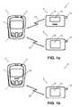
- FIG. 1 ashows a schematic representation of a blood glucose system according to the present invention.
- FIG. 1 bshows a schematic representation of a further blood glucose system according to the present invention.
- FIG. 2 ashows a schematic block diagram of the main components of the controller forming part of a blood glucose system according to the present invention.
- FIG. 2 bshows a schematic block diagram of the main components of a slave device forming part of a blood glucose system according to the present invention.
- FIG. 3 ais a schematic flowchart diagram illustrating the controller side of a preferred embodiment of the method in accordance with the present invention.
- FIG. 3 bis a schematic flowchart diagram illustrating the slave side of a preferred embodiment of the method in accordance with the present invention.
- FIG. 4is a schematic illustration of a data frame.
- FIG. 5 ais a schematic flowchart diagram illustrating the slave side of a delayed response mechanism.
- FIG. 5 bis a schematic flowchart diagram illustrating the controller side of the delayed response mechanism.
- a blood glucose system 1comprising a controller 2 , an insulin pump 3 for dispensing insulin to the blood circuit of a patient, and a blood glucose measuring device 4 for determining the level of blood glucose.
- the controller 2includes a housing 5 , a display 6 and a number of control keys 7 which may be utilized to initiate a particular action by the controller 2 or to input data into the controller 2 , e.g. in order to adjust the operation of the insulin pump 3 with regard to various patient parameters such as e.g. his or her weight. Further main components of the controller 2 are depicted in the schematic block diagram shown in FIG. 2 a .
- the controller 2further comprises a battery 8 , a transmitter 9 , a receiver 10 , an antenna 11 coupled to the transmitter 9 and the receiver 10 , and a clock 23 .
- the operation of the controller 2is controlled by control electronics 12 .
- the control electronics 12are operable to compose data frames to be transmitted by means of the transmitter 9 , to analyze data frames received by the receiver 10 , and to activate and deactivate the transmitter 9 and the receiver 10 to transmit and receive, respectively, data frames.
- the control electronics 12may provide timer functions (creating, starting and stopping timers) and to define and create timer events.
- the insulin pump 3 and the blood glucose measuring device 4each comprise a housing 13 , a display 14 and an antenna 15 . Further main components of the of the insulin pump 3 and the measuring device 4 are depicted in the schematic block diagram shown in FIG. 2 b . Accordingly, the insulin pump 3 and the measuring device 4 further comprise a battery 17 , a transmitter 18 and a receiver 19 which are both coupled to the antenna 15 , and a clock 24 .
- the operation of the controller 2is controlled by control electronics 21 .
- the control electronics 21are operable to compose data frames to be transmitted by means of the transmitter 18 , to analyze data frames received by the receiver 19 , and to activate and deactivate the transmitter 18 and the receiver 19 to transmit and receive, respectively, data frames.
- the control electronics 12may provide timer functions (creating, starting and stopping timers) and to define and create timer events. Both devices also comprise a functional block 20 .
- the block 20is an insulin dispensing means
- the block 20is a glucose sensing means that is able to analyze blood samples on enzyme-based test strips, that can be inserted into a test strip receiving slot 16 , in order to determine the blood glucose level based on the enzymatic reaction.
- the controller 2communicates with the devices 3 and 4 via an RF air interface 22 , which may e.g.
- Manchester codingmay be utilized to allow for automatic balancing of the receivers and to test for Manchester violations.
- the data ratemay e.g. be 9600 bps.
- FIG. 1 bschematically shows an alternative blood glucose system 1 ′.
- the system 1 ′comprises a controller 2 ′ and an insulin pump 3 for dispensing insulin to the blood circuit of a patient.
- the system 1 ′does not comprise a separate blood glucose measuring device 4 .
- a blood glucose measuring means and a test strip receiving slot 16 ′are integrated into the controller 2 ′, i.e. the controller 2 and the blood glucose measuring device 4 of the system 1 shown in FIG. 1 a are combined into a single device 2 ′ having a common housing 5 .
- the insulin pump 3is illustrated as an external device to be worn on the body of a patient.
- the insulin pump 3may also be constructed as an implantable device to be disposed subcutaneously.
- the controller 2 , 2 ′is configured as master and the devices 3 and 4 are configured as slaves, i.e. they never initiate a communication but only respond to commands received from the controller 2 , 2 ′.
- the controller 2 , 2 ′ and the slave devices 3 , 4communicate by exchanging data frames, wherein each transmission preferably consists of one data frame only.
- One such data frame 300is shown schematically in FIG. 4 .
- the data frame 300comprises a preamble portion 301 , an address header 302 (comprising a target address portion 303 , a command portion 304 and optional further header portions (not shown) such as a checksum portion, a source address portion and/or a frame number or frame reference portion) and an optional data portion 305 .
- the length of the preamble portion 301is variable to includes an adjustable number of preamble bytes having a characteristic bit pattern (e.g. 01010101), so that upon transmission of the data frame a characteristic preamble signal is transmitted for an adjustable period of time (preamble period).
- Each data frame 300is addressed to a particular recipient. In order to indicate the intended recipient, the sender includes a predefined target device address into the target address portion 303 .
- the type of data framei.e. command or response
- the type of commandare identified by a unique command or response identifier included in the command portion 304 .
- the control electronics 12 , 21can determine whether the respective device is the intended recipient. Further, it can be determined which command or response the controller 2 , 2 ′ or the devices 3 , 4 , respectively, have sent. Some commands may require further information to be transmitted to the recipient. Such information may be included into the optional data portion 305 . The same applies to additional information, such as status data, transmitted as a response by the devices 3 , 4 .
- FIGS. 3 a and 3 bschematic diagrams of a preferred embodiment of the method according to the present invention is shown, wherein FIG. 3 a shows the steps performed in the controller 2 , 2 ′ and FIG. 3 b shows the steps performed in the insulin pump 3 and the blood glucose measuring device 4 .
- the slave devices 3 , 4normally operate in a power saving mode in which their transmitter 18 and receiver 19 are usually deactivated and in which the receiver 19 is only activated every 3 s for a listening period of 10 ms.
- a mode of operationis commonly termed sniff mode, and the interval between the start times of successive listening periods is referred to as the sniff interval.
- the operation of the slave devices 3 , 4starts in step 200 , in which the sniff interval is set to 3 s. After the sniff interval has elapsed (step 201 ), the receiver 19 is activated in step 202 , and in step 203 it is determined whether a preamble signal can be detected during the listening period of 10 ms.
- the receiver 19is maintained active to receive the remainder of the data frame (step 204 ). Subsequently, the command portion 304 of the received data frame 300 is examined to determine whether it includes the communication initiation command identifier. This particular command is used by the controller 2 , 2 ′ to switch the target device into a communication mode in which the receiver 19 is activated essentially all the time. Accordingly, if it is determined in step 206 that the target address portion 303 includes the address of the respective slave device, the receiver is deactivated (step 207 ) and the slave device is switched to communication mode (step 208 ).
- the transmitter 18is activated and deactivated to transmit a response to the controller 2 , 2 ′ (step 209 ), and then the receiver 19 is again activated (step 210 ) to wait for further data frames 300 from the controller 2 , 2 ′.
- the response to the communication initiation data frameindicates to the controller 2 , 2 ′ that the slave device 3 , 4 is now in communication mode.
- the receiver 19is maintained activated until the preamble signal of a further data frame 300 is detected or until a communication timeout period of e.g. 2 s duration (i.e. longer than the listening period) has elapsed without detection of the preamble signal (step 211 ).
- step 212If a preamble signal of a further data frame is detected in step 211 , the further data frame is received in step 212 . Otherwise, and in case none of the received further data frames are addressed to the slave device, the slave device is switched back to power saving mode (step 214 ). The same happens if the command contained in the command portion 304 of the further data frame 300 indicates that the communication mode shall be terminated immediately (step 213 ). However, if the further data frame 300 received in step 212 is not such a termination data frame, the receiver 19 is deactivated in step 214 to go back to step 209 in order to transmit a response. Depending on the command, such response may be a mere confirmation of receipt or may include data requested by the controller 2 , 2 ′.
- the slave device 3 , 4stays in communication mode, in which the receiver 19 is only deactivated during the time it takes to transmit a response.
- the communication modeis terminated by means of a further data frame 300 including in the command portion 304 a termination command.
- the sniff intervalis adjusted to be 300 ms in order to reduce the delay time in the case of a further communication attempt by the controller 2 , 2 ′.
- step 216when a slave device 3 , 4 receives a data frame 300 including the communication initiation command in the command portion 304 , and determines in step 206 that the address contained in the address portion 303 is not its own address.
- the receiver 19is deactivated for the rest of the sniff interval in step 217 .
- a data frame 300is prepared in the controller 2 , 2 ′ in step 100 ( FIG. 3 a ).
- the address of the target deviceis included into the target address portion 303 (step 101 )
- the identifier of the communication initiation commandis included into the command portion 304 (step 102 )
- the number of preamble bytesis chosen such that the preamble period is 325 ms (step 103 ).
- the transmitter 9is activated and deactivated to transmit this data frame 300 , and subsequently the receiver 10 is activated for a response period of 100 ms to wait for a response from the target slave device (e.g. confirmation of receipt).
- the target slave device 3 , 4will only definitely receive the data frame 300 if its sniff interval is currently 300 ms. In this case, the preamble period chosen in step 103 spans the entire sniff interval. If, however, the sniff interval of the slave device 3 , 4 is currently 3 s, the slave device 3 , 4 will probably not detect the preamble signal within one of its listening periods and will thus not send a response.
- step 106if it is determined in step 106 that the slave device 3 , 4 has not transmitted a response, the number of preamble bytes in the preamble portion 301 of the data frame 300 is increase so as to adjust the preamble period to 3025 ms, i.e. to a value spanning an entire 3 s sniff interval. Then, the data frame 300 is retransmitted (step 108 ) and the receiver 10 is activated for 100 ms to wait for a response.
- a further data frame 300is prepared (step 110 ), and in step 111 the address of the slave device 3 , 4 is included in the address portion 303 , a suitable command is included in the command portion 304 and optionally additional data are included in data portion 305 .
- the control electronics 12 in combination with the clock 23always track the time since transmitting the last data frame to the current slave device, and in step 112 the control electronics 12 compare this time with the communication timeout period in order to determine whether the slave device is still in communication mode.
- the preamble periodis set to 25 ms in step 114 . This minimal preamble period is sufficient since the target slave device is in communication mode so that its receiver 19 is activated. However, it is necessary to transmit the further data frames timely enough for the slave device to still be in communication mode, i.e. the time interval between successive data frames must be smaller than the communication timeout period. Otherwise, if the above determination is negative, the controller goes back to step 100 to initiate another communication cycle with the slave device (step 113 ). Then, the further data frame 300 is transmitted in step 115 , followed by activating the receiver 9 for 100 ms to wait for a response (step 116 ).
- the target slavehas to respond within 100 ms of receipt of a data frame. If the controller 2 , 2 ′ does not receive a response within this response time (step 117 ), it goes back to step 115 in order to retransmit the further data frame. If it is determined that further commands shall be transmitted to the same slave device (step 118 ), another further data frame 300 is prepared in step 110 . Otherwise, a data frame 300 including a termination command in its command portion 304 is prepared and transmitted to the slave device in step 119 in order to effect its switching back to power saving mode.
- a slave device 3 , 4which just has received a further data frame from the controller 2 , 2 ′, may not be able to transmit a response within the response time period of the controller 2 , 2 ′.
- the further data frameincludes a command requesting the slave device 3 , 4 to collect data and provide these data to the controller 2 , 2 ′
- the necessary datamay not be available immediately.
- the slave device 3 , 4has the possibility of delaying transmission of the response in step 209 and to perform the steps of FIG. 5 a instead.
- step 500it is determined by means of the control electronics 21 whether the data requested by the controller 2 , 2 ′ are currently available.
- step 501a data frame is transmitted that includes a delay time period indication (step 502 ), and the receiver 18 and the transmitter 19 of the slave device 3 , 4 is deactivated for the corresponding delay time period (step 503 ) in order to save energy.
- the receiver 18is activated in step 504 until a further data frame including a request to transmit the delayed response is received in step 505 .
- the receiveris deactivated in step 506 , and the method proceeds to step 209 (step 507 ) in order to finally transmit the response to the original further data frame.
- the controller 2 , 2 ′does not only determine whether a response has been received in step 117 , but the control electronics 12 further examine the received response to determine whether it includes a delay time indication (which could e.g. be represented by a suitable command and additional data specifying the delay time period). If no delay time indication is found, the method proceeds to step 118 (step 511 ). On the other hand, in case a delay time indication is found, the control electronics 12 effect deactivation of the receiver 10 and the transmitter 9 for the corresponding delay time period (step 512 ) in order to save energy.
- a delay time indicationwhich could e.g. be represented by a suitable command and additional data specifying the delay time period.
- the control electronics 12After the delay time period has elapsed (as determined by the control electronics 12 in combination with the clock 23 ), the control electronics 12 prepare a further data frame (step 513 ), include a target device indication (step 514 ), and include a request command and additional data requesting the target slave device to transmit a response to a particular earlier data frame (step 515 ). Then, the preamble period is set to 25 ms in step 516 (which is sufficient because the target slave device has activated its receiver after the delay time period has elapsed), and the request data frame is transmitted in step 517 . Finally, the method proceeds to step 116 (step 518 ) to wait for the requested response.
Landscapes
- Health & Medical Sciences (AREA)
- Life Sciences & Earth Sciences (AREA)
- Engineering & Computer Science (AREA)
- Computer Networks & Wireless Communication (AREA)
- Physics & Mathematics (AREA)
- Heart & Thoracic Surgery (AREA)
- Biomedical Technology (AREA)
- Animal Behavior & Ethology (AREA)
- General Health & Medical Sciences (AREA)
- Public Health (AREA)
- Veterinary Medicine (AREA)
- Signal Processing (AREA)
- Pathology (AREA)
- Biophysics (AREA)
- Medical Informatics (AREA)
- Molecular Biology (AREA)
- Surgery (AREA)
- Medicinal Chemistry (AREA)
- Bioinformatics & Cheminformatics (AREA)
- Pharmacology & Pharmacy (AREA)
- Emergency Medicine (AREA)
- Optics & Photonics (AREA)
- Chemical & Material Sciences (AREA)
- Vascular Medicine (AREA)
- Anesthesiology (AREA)
- Hematology (AREA)
- Diabetes (AREA)
- External Artificial Organs (AREA)
- Selective Calling Equipment (AREA)
- Mobile Radio Communication Systems (AREA)
- Infusion, Injection, And Reservoir Apparatuses (AREA)
- Measurement Of The Respiration, Hearing Ability, Form, And Blood Characteristics Of Living Organisms (AREA)
- Investigating Or Analysing Biological Materials (AREA)
Abstract
Description
Claims (23)
Applications Claiming Priority (1)
| Application Number | Priority Date | Filing Date | Title |
|---|---|---|---|
| PCT/EP2006/003650WO2007121763A1 (en) | 2006-04-20 | 2006-04-20 | Method for transmitting data in a blood glucose system and corresponding blood glucose system |
Related Parent Applications (1)
| Application Number | Title | Priority Date | Filing Date |
|---|---|---|---|
| PCT/EP2006/003650A-371-Of-InternationalWO2007121763A1 (en) | 2006-04-20 | 2006-04-20 | Method for transmitting data in a blood glucose system and corresponding blood glucose system |
Related Child Applications (1)
| Application Number | Title | Priority Date | Filing Date |
|---|---|---|---|
| US13/347,937ContinuationUS8472913B2 (en) | 2006-04-20 | 2012-01-11 | Method for transmitting data in a blood glucose system and corresponding blood glucose system |
Publications (2)
| Publication Number | Publication Date |
|---|---|
| US20090216100A1 US20090216100A1 (en) | 2009-08-27 |
| US8099074B2true US8099074B2 (en) | 2012-01-17 |
Family
ID=37695940
Family Applications (3)
| Application Number | Title | Priority Date | Filing Date |
|---|---|---|---|
| US12/297,621Expired - Fee RelatedUS8099074B2 (en) | 2006-04-20 | 2006-04-20 | Method for transmitting data in a blood glucose system and corresponding blood glucose system |
| US13/347,937Expired - Fee RelatedUS8472913B2 (en) | 2006-04-20 | 2012-01-11 | Method for transmitting data in a blood glucose system and corresponding blood glucose system |
| US13/925,550ActiveUS8903350B2 (en) | 2006-04-20 | 2013-06-24 | Method for transmitting data in a blood glucose system and corresponding blood glucose system |
Family Applications After (2)
| Application Number | Title | Priority Date | Filing Date |
|---|---|---|---|
| US13/347,937Expired - Fee RelatedUS8472913B2 (en) | 2006-04-20 | 2012-01-11 | Method for transmitting data in a blood glucose system and corresponding blood glucose system |
| US13/925,550ActiveUS8903350B2 (en) | 2006-04-20 | 2013-06-24 | Method for transmitting data in a blood glucose system and corresponding blood glucose system |
Country Status (9)
| Country | Link |
|---|---|
| US (3) | US8099074B2 (en) |
| EP (1) | EP2011283B1 (en) |
| JP (1) | JP4964946B2 (en) |
| CN (1) | CN101461197B (en) |
| AT (1) | ATE449518T1 (en) |
| CA (1) | CA2649563C (en) |
| DE (1) | DE602006010603D1 (en) |
| ES (1) | ES2336360T3 (en) |
| WO (1) | WO2007121763A1 (en) |
Cited By (12)
| Publication number | Priority date | Publication date | Assignee | Title |
|---|---|---|---|---|
| US20100213080A1 (en)* | 2009-02-23 | 2010-08-26 | Celentano Michael J | System and method for the electrochemical measurement of an analyte employing a remote sensor |
| US20120163481A1 (en)* | 2006-04-20 | 2012-06-28 | Lifescan Scotland Ltd. | Method for transmitting data in a blood glucose system and corresponding blood glucose system |
| US20130094459A1 (en)* | 2011-10-14 | 2013-04-18 | Texas Instruments Incorporated | Beacon Slot Allocation in Prime |
| US20140256259A1 (en)* | 2013-03-07 | 2014-09-11 | Plastoform Industries Limited | Bluetooth Communication System And Method For Selectively Switching Modes Of Operation In Between Electronic Devices |
| US8961432B2 (en) | 2011-06-21 | 2015-02-24 | Yofimeter, Llc | Analyte testing devices |
| US9486571B2 (en) | 2013-12-26 | 2016-11-08 | Tandem Diabetes Care, Inc. | Safety processor for wireless control of a drug delivery device |
| US20170142658A1 (en)* | 2015-11-17 | 2017-05-18 | Tandem Diabetes Care, Inc. | Methods for reduction of battery usage in ambulatory infusion pumps |
| US9737656B2 (en) | 2013-12-26 | 2017-08-22 | Tandem Diabetes Care, Inc. | Integration of infusion pump with remote electronic device |
| US10049768B2 (en) | 2002-02-28 | 2018-08-14 | Tandem Diabetes Care, Inc. | Programmable insulin pump |
| US20190188174A1 (en)* | 2017-12-14 | 2019-06-20 | Texas Instruments Incorporated | Multi-slave serial communication |
| US10430043B2 (en) | 2012-06-07 | 2019-10-01 | Tandem Diabetes Care, Inc. | Preventing inadvertent changes in ambulatory medical devices |
| US10453566B2 (en) | 2013-04-26 | 2019-10-22 | Roche Diabetes Care, Inc. | Method for reconciling medical data captured on one device with a structured test administered on another device |
Families Citing this family (201)
| Publication number | Priority date | Publication date | Assignee | Title |
|---|---|---|---|---|
| US6391005B1 (en) | 1998-03-30 | 2002-05-21 | Agilent Technologies, Inc. | Apparatus and method for penetration with shaft having a sensor for sensing penetration depth |
| US9066695B2 (en) | 1998-04-30 | 2015-06-30 | Abbott Diabetes Care Inc. | Analyte monitoring device and methods of use |
| US6949816B2 (en) | 2003-04-21 | 2005-09-27 | Motorola, Inc. | Semiconductor component having first surface area for electrically coupling to a semiconductor chip and second surface area for electrically coupling to a substrate, and method of manufacturing same |
| US8346337B2 (en) | 1998-04-30 | 2013-01-01 | Abbott Diabetes Care Inc. | Analyte monitoring device and methods of use |
| US8974386B2 (en) | 1998-04-30 | 2015-03-10 | Abbott Diabetes Care Inc. | Analyte monitoring device and methods of use |
| US6175752B1 (en) | 1998-04-30 | 2001-01-16 | Therasense, Inc. | Analyte monitoring device and methods of use |
| US8480580B2 (en) | 1998-04-30 | 2013-07-09 | Abbott Diabetes Care Inc. | Analyte monitoring device and methods of use |
| US8688188B2 (en) | 1998-04-30 | 2014-04-01 | Abbott Diabetes Care Inc. | Analyte monitoring device and methods of use |
| US8465425B2 (en) | 1998-04-30 | 2013-06-18 | Abbott Diabetes Care Inc. | Analyte monitoring device and methods of use |
| US8641644B2 (en) | 2000-11-21 | 2014-02-04 | Sanofi-Aventis Deutschland Gmbh | Blood testing apparatus having a rotatable cartridge with multiple lancing elements and testing means |
| US6560471B1 (en) | 2001-01-02 | 2003-05-06 | Therasense, Inc. | Analyte monitoring device and methods of use |
| US9795747B2 (en) | 2010-06-02 | 2017-10-24 | Sanofi-Aventis Deutschland Gmbh | Methods and apparatus for lancet actuation |
| US9226699B2 (en) | 2002-04-19 | 2016-01-05 | Sanofi-Aventis Deutschland Gmbh | Body fluid sampling module with a continuous compression tissue interface surface |
| US9427532B2 (en) | 2001-06-12 | 2016-08-30 | Sanofi-Aventis Deutschland Gmbh | Tissue penetration device |
| US8337419B2 (en) | 2002-04-19 | 2012-12-25 | Sanofi-Aventis Deutschland Gmbh | Tissue penetration device |
| US7749174B2 (en) | 2001-06-12 | 2010-07-06 | Pelikan Technologies, Inc. | Method and apparatus for lancet launching device intergrated onto a blood-sampling cartridge |
| US7981056B2 (en) | 2002-04-19 | 2011-07-19 | Pelikan Technologies, Inc. | Methods and apparatus for lancet actuation |
| US7041068B2 (en) | 2001-06-12 | 2006-05-09 | Pelikan Technologies, Inc. | Sampling module device and method |
| US7344507B2 (en) | 2002-04-19 | 2008-03-18 | Pelikan Technologies, Inc. | Method and apparatus for lancet actuation |
| JP4209767B2 (en) | 2001-06-12 | 2009-01-14 | ペリカン テクノロジーズ インコーポレイテッド | Self-optimized cutting instrument with adaptive means for temporary changes in skin properties |
| EP1395185B1 (en) | 2001-06-12 | 2010-10-27 | Pelikan Technologies Inc. | Electric lancet actuator |
| US8702624B2 (en) | 2006-09-29 | 2014-04-22 | Sanofi-Aventis Deutschland Gmbh | Analyte measurement device with a single shot actuator |
| US7232451B2 (en) | 2002-04-19 | 2007-06-19 | Pelikan Technologies, Inc. | Method and apparatus for penetrating tissue |
| US9795334B2 (en) | 2002-04-19 | 2017-10-24 | Sanofi-Aventis Deutschland Gmbh | Method and apparatus for penetrating tissue |
| US7976476B2 (en) | 2002-04-19 | 2011-07-12 | Pelikan Technologies, Inc. | Device and method for variable speed lancet |
| US8372016B2 (en) | 2002-04-19 | 2013-02-12 | Sanofi-Aventis Deutschland Gmbh | Method and apparatus for body fluid sampling and analyte sensing |
| US7674232B2 (en) | 2002-04-19 | 2010-03-09 | Pelikan Technologies, Inc. | Method and apparatus for penetrating tissue |
| US9314194B2 (en) | 2002-04-19 | 2016-04-19 | Sanofi-Aventis Deutschland Gmbh | Tissue penetration device |
| US7901362B2 (en) | 2002-04-19 | 2011-03-08 | Pelikan Technologies, Inc. | Method and apparatus for penetrating tissue |
| US8579831B2 (en) | 2002-04-19 | 2013-11-12 | Sanofi-Aventis Deutschland Gmbh | Method and apparatus for penetrating tissue |
| US7229458B2 (en) | 2002-04-19 | 2007-06-12 | Pelikan Technologies, Inc. | Method and apparatus for penetrating tissue |
| US8360992B2 (en) | 2002-04-19 | 2013-01-29 | Sanofi-Aventis Deutschland Gmbh | Method and apparatus for penetrating tissue |
| US7708701B2 (en) | 2002-04-19 | 2010-05-04 | Pelikan Technologies, Inc. | Method and apparatus for a multi-use body fluid sampling device |
| US7297122B2 (en) | 2002-04-19 | 2007-11-20 | Pelikan Technologies, Inc. | Method and apparatus for penetrating tissue |
| US8221334B2 (en) | 2002-04-19 | 2012-07-17 | Sanofi-Aventis Deutschland Gmbh | Method and apparatus for penetrating tissue |
| US7331931B2 (en) | 2002-04-19 | 2008-02-19 | Pelikan Technologies, Inc. | Method and apparatus for penetrating tissue |
| US7547287B2 (en) | 2002-04-19 | 2009-06-16 | Pelikan Technologies, Inc. | Method and apparatus for penetrating tissue |
| US9248267B2 (en) | 2002-04-19 | 2016-02-02 | Sanofi-Aventis Deustchland Gmbh | Tissue penetration device |
| US8784335B2 (en) | 2002-04-19 | 2014-07-22 | Sanofi-Aventis Deutschland Gmbh | Body fluid sampling device with a capacitive sensor |
| US7892183B2 (en) | 2002-04-19 | 2011-02-22 | Pelikan Technologies, Inc. | Method and apparatus for body fluid sampling and analyte sensing |
| US7909778B2 (en) | 2002-04-19 | 2011-03-22 | Pelikan Technologies, Inc. | Method and apparatus for penetrating tissue |
| US8267870B2 (en) | 2002-04-19 | 2012-09-18 | Sanofi-Aventis Deutschland Gmbh | Method and apparatus for body fluid sampling with hybrid actuation |
| US7491178B2 (en) | 2002-04-19 | 2009-02-17 | Pelikan Technologies, Inc. | Method and apparatus for penetrating tissue |
| US8574895B2 (en) | 2002-12-30 | 2013-11-05 | Sanofi-Aventis Deutschland Gmbh | Method and apparatus using optical techniques to measure analyte levels |
| US7811231B2 (en) | 2002-12-31 | 2010-10-12 | Abbott Diabetes Care Inc. | Continuous glucose monitoring system and methods of use |
| US7587287B2 (en) | 2003-04-04 | 2009-09-08 | Abbott Diabetes Care Inc. | Method and system for transferring analyte test data |
| DE602004028463D1 (en) | 2003-05-30 | 2010-09-16 | Pelikan Technologies Inc | METHOD AND DEVICE FOR INJECTING LIQUID |
| US7850621B2 (en) | 2003-06-06 | 2010-12-14 | Pelikan Technologies, Inc. | Method and apparatus for body fluid sampling and analyte sensing |
| US8066639B2 (en) | 2003-06-10 | 2011-11-29 | Abbott Diabetes Care Inc. | Glucose measuring device for use in personal area network |
| WO2006001797A1 (en) | 2004-06-14 | 2006-01-05 | Pelikan Technologies, Inc. | Low pain penetrating |
| US8282576B2 (en) | 2003-09-29 | 2012-10-09 | Sanofi-Aventis Deutschland Gmbh | Method and apparatus for an improved sample capture device |
| EP1680014A4 (en) | 2003-10-14 | 2009-01-21 | Pelikan Technologies Inc | METHOD AND DEVICE FOR A VARIABLE USER INTERFACE |
| US7822454B1 (en) | 2005-01-03 | 2010-10-26 | Pelikan Technologies, Inc. | Fluid sampling device with improved analyte detecting member configuration |
| US8668656B2 (en) | 2003-12-31 | 2014-03-11 | Sanofi-Aventis Deutschland Gmbh | Method and apparatus for improving fluidic flow and sample capture |
| WO2005089103A2 (en) | 2004-02-17 | 2005-09-29 | Therasense, Inc. | Method and system for providing data communication in continuous glucose monitoring and management system |
| WO2006011062A2 (en) | 2004-05-20 | 2006-02-02 | Albatros Technologies Gmbh & Co. Kg | Printable hydrogel for biosensors |
| US9775553B2 (en) | 2004-06-03 | 2017-10-03 | Sanofi-Aventis Deutschland Gmbh | Method and apparatus for a fluid sampling device |
| WO2005120365A1 (en) | 2004-06-03 | 2005-12-22 | Pelikan Technologies, Inc. | Method and apparatus for a fluid sampling device |
| US9788771B2 (en) | 2006-10-23 | 2017-10-17 | Abbott Diabetes Care Inc. | Variable speed sensor insertion devices and methods of use |
| US7697967B2 (en) | 2005-12-28 | 2010-04-13 | Abbott Diabetes Care Inc. | Method and apparatus for providing analyte sensor insertion |
| US9636450B2 (en) | 2007-02-19 | 2017-05-02 | Udo Hoss | Pump system modular components for delivering medication and analyte sensing at seperate insertion sites |
| US8652831B2 (en) | 2004-12-30 | 2014-02-18 | Sanofi-Aventis Deutschland Gmbh | Method and apparatus for analyte measurement test time |
| EP1935139B1 (en)* | 2005-09-13 | 2009-08-26 | France Telecom | Method and system for transmitting a signal comprising a preamble and a data frame |
| US8880138B2 (en) | 2005-09-30 | 2014-11-04 | Abbott Diabetes Care Inc. | Device for channeling fluid and methods of use |
| US7766829B2 (en) | 2005-11-04 | 2010-08-03 | Abbott Diabetes Care Inc. | Method and system for providing basal profile modification in analyte monitoring and management systems |
| US11298058B2 (en) | 2005-12-28 | 2022-04-12 | Abbott Diabetes Care Inc. | Method and apparatus for providing analyte sensor insertion |
| US7736310B2 (en) | 2006-01-30 | 2010-06-15 | Abbott Diabetes Care Inc. | On-body medical device securement |
| US7981034B2 (en) | 2006-02-28 | 2011-07-19 | Abbott Diabetes Care Inc. | Smart messages and alerts for an infusion delivery and management system |
| US7826879B2 (en) | 2006-02-28 | 2010-11-02 | Abbott Diabetes Care Inc. | Analyte sensors and methods of use |
| US7620438B2 (en) | 2006-03-31 | 2009-11-17 | Abbott Diabetes Care Inc. | Method and system for powering an electronic device |
| US8374668B1 (en) | 2007-10-23 | 2013-02-12 | Abbott Diabetes Care Inc. | Analyte sensor with lag compensation |
| US8226891B2 (en) | 2006-03-31 | 2012-07-24 | Abbott Diabetes Care Inc. | Analyte monitoring devices and methods therefor |
| US8346335B2 (en) | 2008-03-28 | 2013-01-01 | Abbott Diabetes Care Inc. | Analyte sensor calibration management |
| US7618369B2 (en) | 2006-10-02 | 2009-11-17 | Abbott Diabetes Care Inc. | Method and system for dynamically updating calibration parameters for an analyte sensor |
| US9392969B2 (en) | 2008-08-31 | 2016-07-19 | Abbott Diabetes Care Inc. | Closed loop control and signal attenuation detection |
| US8473022B2 (en) | 2008-01-31 | 2013-06-25 | Abbott Diabetes Care Inc. | Analyte sensor with time lag compensation |
| US7653425B2 (en) | 2006-08-09 | 2010-01-26 | Abbott Diabetes Care Inc. | Method and system for providing calibration of an analyte sensor in an analyte monitoring system |
| US8140312B2 (en) | 2007-05-14 | 2012-03-20 | Abbott Diabetes Care Inc. | Method and system for determining analyte levels |
| US8478557B2 (en) | 2009-07-31 | 2013-07-02 | Abbott Diabetes Care Inc. | Method and apparatus for providing analyte monitoring system calibration accuracy |
| WO2007143225A2 (en) | 2006-06-07 | 2007-12-13 | Abbott Diabetes Care, Inc. | Analyte monitoring system and method |
| US8206296B2 (en) | 2006-08-07 | 2012-06-26 | Abbott Diabetes Care Inc. | Method and system for providing integrated analyte monitoring and infusion system therapy management |
| US8932216B2 (en) | 2006-08-07 | 2015-01-13 | Abbott Diabetes Care Inc. | Method and system for providing data management in integrated analyte monitoring and infusion system |
| US20080199894A1 (en) | 2007-02-15 | 2008-08-21 | Abbott Diabetes Care, Inc. | Device and method for automatic data acquisition and/or detection |
| US8123686B2 (en) | 2007-03-01 | 2012-02-28 | Abbott Diabetes Care Inc. | Method and apparatus for providing rolling data in communication systems |
| US20080228056A1 (en) | 2007-03-13 | 2008-09-18 | Michael Blomquist | Basal rate testing using frequent blood glucose input |
| WO2008130898A1 (en) | 2007-04-14 | 2008-10-30 | Abbott Diabetes Care, Inc. | Method and apparatus for providing data processing and control in medical communication system |
| US10111608B2 (en) | 2007-04-14 | 2018-10-30 | Abbott Diabetes Care Inc. | Method and apparatus for providing data processing and control in medical communication system |
| CA2683953C (en) | 2007-04-14 | 2016-08-02 | Abbott Diabetes Care Inc. | Method and apparatus for providing data processing and control in medical communication system |
| WO2008130897A2 (en) | 2007-04-14 | 2008-10-30 | Abbott Diabetes Care, Inc. | Method and apparatus for providing data processing and control in medical communication system |
| US7928850B2 (en) | 2007-05-08 | 2011-04-19 | Abbott Diabetes Care Inc. | Analyte monitoring system and methods |
| US8461985B2 (en) | 2007-05-08 | 2013-06-11 | Abbott Diabetes Care Inc. | Analyte monitoring system and methods |
| US8456301B2 (en) | 2007-05-08 | 2013-06-04 | Abbott Diabetes Care Inc. | Analyte monitoring system and methods |
| US8665091B2 (en) | 2007-05-08 | 2014-03-04 | Abbott Diabetes Care Inc. | Method and device for determining elapsed sensor life |
| US8560038B2 (en) | 2007-05-14 | 2013-10-15 | Abbott Diabetes Care Inc. | Method and apparatus for providing data processing and control in a medical communication system |
| US8239166B2 (en) | 2007-05-14 | 2012-08-07 | Abbott Diabetes Care Inc. | Method and apparatus for providing data processing and control in a medical communication system |
| US8103471B2 (en) | 2007-05-14 | 2012-01-24 | Abbott Diabetes Care Inc. | Method and apparatus for providing data processing and control in a medical communication system |
| US8600681B2 (en) | 2007-05-14 | 2013-12-03 | Abbott Diabetes Care Inc. | Method and apparatus for providing data processing and control in a medical communication system |
| US8260558B2 (en) | 2007-05-14 | 2012-09-04 | Abbott Diabetes Care Inc. | Method and apparatus for providing data processing and control in a medical communication system |
| US9125548B2 (en) | 2007-05-14 | 2015-09-08 | Abbott Diabetes Care Inc. | Method and apparatus for providing data processing and control in a medical communication system |
| US8444560B2 (en) | 2007-05-14 | 2013-05-21 | Abbott Diabetes Care Inc. | Method and apparatus for providing data processing and control in a medical communication system |
| US10002233B2 (en) | 2007-05-14 | 2018-06-19 | Abbott Diabetes Care Inc. | Method and apparatus for providing data processing and control in a medical communication system |
| US7751907B2 (en) | 2007-05-24 | 2010-07-06 | Smiths Medical Asd, Inc. | Expert system for insulin pump therapy |
| US8221345B2 (en) | 2007-05-30 | 2012-07-17 | Smiths Medical Asd, Inc. | Insulin pump based expert system |
| US9391670B2 (en) | 2007-06-15 | 2016-07-12 | Animas Corporation | Methods for secure communication and pairing of a medical infusion device and a remote controller for such medical device |
| US8444595B2 (en) | 2007-06-15 | 2013-05-21 | Animas Corporation | Methods to pair a medical device and at least a remote controller for such medical device |
| US8932250B2 (en) | 2007-06-15 | 2015-01-13 | Animas Corporation | Systems and methods to pair a medical device and a remote controller for such medical device |
| US8449523B2 (en) | 2007-06-15 | 2013-05-28 | Animas Corporation | Method of operating a medical device and at least a remote controller for such medical device |
| AU2008265542B2 (en) | 2007-06-21 | 2014-07-24 | Abbott Diabetes Care Inc. | Health monitor |
| WO2008157820A1 (en) | 2007-06-21 | 2008-12-24 | Abbott Diabetes Care, Inc. | Health management devices and methods |
| US8160900B2 (en) | 2007-06-29 | 2012-04-17 | Abbott Diabetes Care Inc. | Analyte monitoring and management device and method to analyze the frequency of user interaction with the device |
| US8834366B2 (en) | 2007-07-31 | 2014-09-16 | Abbott Diabetes Care Inc. | Method and apparatus for providing analyte sensor calibration |
| US8377031B2 (en) | 2007-10-23 | 2013-02-19 | Abbott Diabetes Care Inc. | Closed loop control system with safety parameters and methods |
| US8409093B2 (en) | 2007-10-23 | 2013-04-02 | Abbott Diabetes Care Inc. | Assessing measures of glycemic variability |
| JP5145902B2 (en)* | 2007-11-27 | 2013-02-20 | 日本電気株式会社 | Radio base station apparatus and congestion control method |
| US20090164239A1 (en) | 2007-12-19 | 2009-06-25 | Abbott Diabetes Care, Inc. | Dynamic Display Of Glucose Information |
| US7865351B2 (en)* | 2007-12-30 | 2011-01-04 | Sandisk Il Ltd. | Device and method for automatically launching applications residing on USB flash drives |
| US20090177147A1 (en) | 2008-01-07 | 2009-07-09 | Michael Blomquist | Insulin pump with insulin therapy coaching |
| EP2265324B1 (en) | 2008-04-11 | 2015-01-28 | Sanofi-Aventis Deutschland GmbH | Integrated analyte measurement system |
| US7809873B2 (en)* | 2008-04-11 | 2010-10-05 | Sandisk Il Ltd. | Direct data transfer between slave devices |
| US8145931B2 (en)* | 2008-05-27 | 2012-03-27 | Sharp Laboratories Of America, Inc. | Imaging device with adaptive power saving behavior and method for use thereon |
| US7826382B2 (en) | 2008-05-30 | 2010-11-02 | Abbott Diabetes Care Inc. | Close proximity communication device and methods |
| US20090300616A1 (en)* | 2008-05-30 | 2009-12-03 | Abbott Diabetes Care, Inc. | Automated task execution for an analyte monitoring system |
| US8591410B2 (en) | 2008-05-30 | 2013-11-26 | Abbott Diabetes Care Inc. | Method and apparatus for providing glycemic control |
| US8924159B2 (en) | 2008-05-30 | 2014-12-30 | Abbott Diabetes Care Inc. | Method and apparatus for providing glycemic control |
| US8876755B2 (en) | 2008-07-14 | 2014-11-04 | Abbott Diabetes Care Inc. | Closed loop control system interface and methods |
| CN102119576B (en)* | 2008-08-11 | 2013-11-20 | 皇家飞利浦电子股份有限公司 | Duty cycling techniques in medium access control (MAC) protocols for body area networks |
| US20100057040A1 (en) | 2008-08-31 | 2010-03-04 | Abbott Diabetes Care, Inc. | Robust Closed Loop Control And Methods |
| US9943644B2 (en) | 2008-08-31 | 2018-04-17 | Abbott Diabetes Care Inc. | Closed loop control with reference measurement and methods thereof |
| US8622988B2 (en) | 2008-08-31 | 2014-01-07 | Abbott Diabetes Care Inc. | Variable rate closed loop control and methods |
| US8734422B2 (en) | 2008-08-31 | 2014-05-27 | Abbott Diabetes Care Inc. | Closed loop control with improved alarm functions |
| DE102008047246A1 (en)* | 2008-09-10 | 2010-04-15 | Siemens Aktiengesellschaft | Method for activating an electrical device and electrical device and arrangement |
| US8986208B2 (en) | 2008-09-30 | 2015-03-24 | Abbott Diabetes Care Inc. | Analyte sensor sensitivity attenuation mitigation |
| US8194902B2 (en)* | 2008-12-22 | 2012-06-05 | Gn Resound A/S | Wireless network protocol for a hearing system |
| US9375169B2 (en) | 2009-01-30 | 2016-06-28 | Sanofi-Aventis Deutschland Gmbh | Cam drive for managing disposable penetrating member actions with a single motor and motor and control system |
| US9402544B2 (en) | 2009-02-03 | 2016-08-02 | Abbott Diabetes Care Inc. | Analyte sensor and apparatus for insertion of the sensor |
| JP5223732B2 (en)* | 2009-03-04 | 2013-06-26 | 株式会社リコー | Information processing apparatus, information processing method, and program |
| US8497777B2 (en) | 2009-04-15 | 2013-07-30 | Abbott Diabetes Care Inc. | Analyte monitoring system having an alert |
| WO2010127050A1 (en) | 2009-04-28 | 2010-11-04 | Abbott Diabetes Care Inc. | Error detection in critical repeating data in a wireless sensor system |
| US8368556B2 (en) | 2009-04-29 | 2013-02-05 | Abbott Diabetes Care Inc. | Method and system for providing data communication in continuous glucose monitoring and management system |
| EP2425209A4 (en) | 2009-04-29 | 2013-01-09 | Abbott Diabetes Care Inc | METHOD AND SYSTEM FOR PROVIDING REAL-TIME ANALYTE SENSOR CALIBRATION WITH RETROSPECTIVE FILLING |
| WO2010135646A1 (en) | 2009-05-22 | 2010-11-25 | Abbott Diabetes Care Inc. | Usability features for integrated insulin delivery system |
| WO2010138856A1 (en) | 2009-05-29 | 2010-12-02 | Abbott Diabetes Care Inc. | Medical device antenna systems having external antenna configurations |
| WO2010141922A1 (en)* | 2009-06-04 | 2010-12-09 | Abbott Diabetes Care Inc. | Method and system for updating a medical device |
| US8344847B2 (en)* | 2009-07-09 | 2013-01-01 | Medtronic Minimed, Inc. | Coordination of control commands in a medical device system having at least one therapy delivery device and at least one wireless controller device |
| US8798934B2 (en) | 2009-07-23 | 2014-08-05 | Abbott Diabetes Care Inc. | Real time management of data relating to physiological control of glucose levels |
| DK3689237T3 (en) | 2009-07-23 | 2021-08-16 | Abbott Diabetes Care Inc | Method of preparation and system for continuous analyte measurement |
| EP3001194B1 (en) | 2009-08-31 | 2019-04-17 | Abbott Diabetes Care, Inc. | Medical devices and methods |
| US8993331B2 (en) | 2009-08-31 | 2015-03-31 | Abbott Diabetes Care Inc. | Analyte monitoring system and methods for managing power and noise |
| US9314195B2 (en) | 2009-08-31 | 2016-04-19 | Abbott Diabetes Care Inc. | Analyte signal processing device and methods |
| LT4147999T (en) | 2009-08-31 | 2024-10-10 | Abbott Diabetes Care, Inc. | MEDICAL DEVICE DISPLAYS |
| EP2322130B1 (en)* | 2009-11-16 | 2013-01-16 | TRUMPF Medizin Systeme GmbH + Co. KG | Medical supply unit |
| US8882701B2 (en) | 2009-12-04 | 2014-11-11 | Smiths Medical Asd, Inc. | Advanced step therapy delivery for an ambulatory infusion pump and system |
| KR101317178B1 (en)* | 2009-12-21 | 2013-10-15 | 한국전자통신연구원 | ZigBee Gateway and method for identifying message of the same |
| US8965476B2 (en) | 2010-04-16 | 2015-02-24 | Sanofi-Aventis Deutschland Gmbh | Tissue penetration device |
| US11213226B2 (en) | 2010-10-07 | 2022-01-04 | Abbott Diabetes Care Inc. | Analyte monitoring devices and methods |
| US8615277B2 (en)* | 2010-11-12 | 2013-12-24 | Mediatek Inc. | Electronic device having functional blocks individually controlled to selectively enter power-saving mode and related power control method thereof |
| US10136845B2 (en) | 2011-02-28 | 2018-11-27 | Abbott Diabetes Care Inc. | Devices, systems, and methods associated with analyte monitoring devices and devices incorporating the same |
| CN107019515B (en) | 2011-02-28 | 2021-02-26 | 雅培糖尿病护理公司 | Method of displaying sensor readings and analyte monitoring device and method of operating the same |
| US9974472B2 (en) | 2011-06-16 | 2018-05-22 | Abbott Diabetes Care Inc. | Temperature-compensated analyte monitoring devices, systems, and methods thereof |
| US9258720B2 (en) | 2011-08-03 | 2016-02-09 | Draeger Medical Systems, Inc. | Throughput-based active mode trigger |
| US9069536B2 (en) | 2011-10-31 | 2015-06-30 | Abbott Diabetes Care Inc. | Electronic devices having integrated reset systems and methods thereof |
| WO2013070794A2 (en) | 2011-11-07 | 2013-05-16 | Abbott Diabetes Care Inc. | Analyte monitoring device and methods |
| US8710993B2 (en) | 2011-11-23 | 2014-04-29 | Abbott Diabetes Care Inc. | Mitigating single point failure of devices in an analyte monitoring system and methods thereof |
| CN104053467B (en)* | 2011-11-23 | 2017-06-09 | 赛诺菲-安万特德国有限公司 | Method and medical apparatus for adjusting the dosage of fluid medicine |
| US9317656B2 (en) | 2011-11-23 | 2016-04-19 | Abbott Diabetes Care Inc. | Compatibility mechanisms for devices in a continuous analyte monitoring system and methods thereof |
| WO2013078426A2 (en) | 2011-11-25 | 2013-05-30 | Abbott Diabetes Care Inc. | Analyte monitoring system and methods of use |
| US9098610B2 (en)* | 2011-12-22 | 2015-08-04 | Greatbatch Ltd. | Communication for implantable medical devices |
| US9238100B2 (en) | 2012-06-07 | 2016-01-19 | Tandem Diabetes Care, Inc. | Device and method for training users of ambulatory medical devices |
| US10132793B2 (en) | 2012-08-30 | 2018-11-20 | Abbott Diabetes Care Inc. | Dropout detection in continuous analyte monitoring data during data excursions |
| CN104582564B (en)* | 2012-09-03 | 2017-03-15 | 株式会社日立制作所 | Biological signal measuring device and biosignal measurement set |
| US9968306B2 (en) | 2012-09-17 | 2018-05-15 | Abbott Diabetes Care Inc. | Methods and apparatuses for providing adverse condition notification with enhanced wireless communication range in analyte monitoring systems |
| WO2014052136A1 (en) | 2012-09-26 | 2014-04-03 | Abbott Diabetes Care Inc. | Method and apparatus for improving lag correction during in vivo measurement of analyte concentration with analyte concentration variability and range data |
| US9344777B2 (en)* | 2012-12-20 | 2016-05-17 | Abbott Diabetes Care Inc. | Wireless communication authentication for medical monitoring device |
| US10357606B2 (en) | 2013-03-13 | 2019-07-23 | Tandem Diabetes Care, Inc. | System and method for integration of insulin pumps and continuous glucose monitoring |
| EP3409201B1 (en) | 2013-03-15 | 2024-04-10 | Abbott Diabetes Care, Inc. | System and method to manage diabetes based on glucose median, glucose variability, and hypoglycemic risk |
| US10016561B2 (en) | 2013-03-15 | 2018-07-10 | Tandem Diabetes Care, Inc. | Clinical variable determination |
| US12115375B2 (en) | 2013-11-27 | 2024-10-15 | Pacesetter, Inc. | Medical device and method for managing advertisement period |
| US11007370B2 (en) | 2013-11-27 | 2021-05-18 | Pacesetter, Inc. | System and methods for establishing a communication session between an implantable medical device and an external device |
| EP3082574B1 (en)* | 2013-12-16 | 2023-07-12 | Dexcom, Inc. | Systems and methods for monitoring and managing life of a battery in an analyte sensor system worn by a user |
| DE102014116124A1 (en)* | 2014-11-05 | 2016-05-12 | Andreas E. Hilburg | A method of monitoring communication between a multitasking controller and a wireless metering device and computer program product |
| US10897763B2 (en) | 2015-01-30 | 2021-01-19 | Itron Networked Solutions, Inc. | Techniques for managing heterogenous nodes configured to support a homogeneous communication protocol |
| US10046114B1 (en)* | 2015-05-22 | 2018-08-14 | Verily Life Sciences Llc | Control of a peripheral device with a bandage-type analyte sensor |
| DE202016009220U1 (en) | 2015-07-10 | 2024-07-09 | Abbott Diabetes Care, Inc. | Device and system for dynamic glucose profile response to physiological parameters |
| US10569016B2 (en) | 2015-12-29 | 2020-02-25 | Tandem Diabetes Care, Inc. | System and method for switching between closed loop and open loop control of an ambulatory infusion pump |
| PL3435865T3 (en) | 2016-03-29 | 2025-03-24 | F. Hoffmann-La Roche Ag | Method of operating a receiver for receiving analytical data, the receiver and the product in the form of a computer program |
| HUP1600354A2 (en)* | 2016-06-01 | 2018-03-28 | Gyoergy Zoltan Kozmann | Method and measurement arrangement for monitoring certain functional parameters of the human heart |
| DK3261357T3 (en) | 2016-06-23 | 2019-03-11 | Hoffmann La Roche | PROCEDURE FOR A WIRELESS DATA COMMUNICATION BETWEEN A SENSOR SYSTEM AND A RECEIVER, A SYSTEM FOR A WIRELESS DATA COMMUNICATION AND COMPUTER PROGRAM PRODUCT |
| US10248525B2 (en)* | 2016-10-11 | 2019-04-02 | Bayer Oy | Intelligent medical implant and monitoring system |
| US10278217B2 (en) | 2016-11-29 | 2019-04-30 | Pacesetter, Inc. | Managing dynamic connection intervals for implantable and external devices |
| US11071478B2 (en) | 2017-01-23 | 2021-07-27 | Abbott Diabetes Care Inc. | Systems, devices and methods for analyte sensor insertion |
| US10124182B2 (en)* | 2017-02-28 | 2018-11-13 | Medtronic, Inc. | Mitigating implantable device power drain associated with stalled telemetry sessions |
| WO2018175489A1 (en) | 2017-03-21 | 2018-09-27 | Abbott Diabetes Care Inc. | Methods, devices and system for providing diabetic condition diagnosis and therapy |
| CN110495220B (en)* | 2017-03-31 | 2021-11-02 | 中兴通讯股份有限公司 | Method and apparatus for synchronization of low power devices |
| JP7219769B2 (en)* | 2017-12-12 | 2023-02-08 | コーニンクレッカ フィリップス エヌ ヴェ | Methods and systems for improved motion robustness during measurements of focal oral inflammation |
| US11850045B2 (en) | 2018-05-04 | 2023-12-26 | Dexcom, Inc. | Systems and methods relating to an analyte sensor system having a battery located within a disposable base |
| US11646833B2 (en)* | 2018-07-24 | 2023-05-09 | Koninklijke Kpn N.V. | Reliable communication over shared resources |
| US10785720B2 (en) | 2019-01-23 | 2020-09-22 | Pacesetter, Inc. | Medical device with control circuitry to improve communication quality |
| CN110812598A (en)* | 2019-11-20 | 2020-02-21 | 周刚 | Capacitance type infusion allowance calculation and alarm method with temperature self-calibration function |
| EP4096752A4 (en)* | 2020-01-30 | 2024-06-12 | Willow Laboratories, Inc. | Redundant staggered glucose sensor disease management system |
| CA3188510A1 (en) | 2020-08-31 | 2022-03-03 | Vivek S. RAO | Systems, devices, and methods for analyte sensor insertion |
| WO2024258732A2 (en)* | 2023-06-13 | 2024-12-19 | Dionex Corporation | Instrument integrity and health operations |
Citations (32)
| Publication number | Priority date | Publication date | Assignee | Title |
|---|---|---|---|---|
| US5394882A (en) | 1993-07-21 | 1995-03-07 | Respironics, Inc. | Physiological monitoring system |
| US5566081A (en) | 1992-10-23 | 1996-10-15 | Nec Corporation | Method of saving power consumption in a battery operated pager receiver |
| JPH0965464A (en) | 1995-08-22 | 1997-03-07 | Matsushita Electric Ind Co Ltd | Wireless communication device |
| US6067234A (en) | 1997-12-22 | 2000-05-23 | International Business Machines Corporation | Adaptor connection apparatus for a data processing system |
| US6167303A (en) | 1998-04-29 | 2000-12-26 | Medtronic, Inc. | Power consumption reduction in medical devices employing just-in-time clock |
| US6241557B1 (en) | 1999-03-26 | 2001-06-05 | Amphenol-Tuchel Electronics Gmbh | Smart card connector |
| US6244902B1 (en) | 1999-05-05 | 2001-06-12 | Thomas & Betts International, Inc. | Smart card reader for elevated placement relative to a printed circuit board |
| WO2002037714A1 (en) | 2000-11-06 | 2002-05-10 | Motorola Inc | Method and apparatus to synchronize mobile radios |
| US6441747B1 (en)* | 2000-04-18 | 2002-08-27 | Motorola, Inc. | Wireless system protocol for telemetry monitoring |
| US20030065536A1 (en) | 2001-08-13 | 2003-04-03 | Hansen Henrik Egesborg | Portable device and method of communicating medical data information |
| US20030087681A1 (en) | 2001-10-25 | 2003-05-08 | William Sackett | Method of and arrangement for minimizing power consumption and data latency of an electro-optical reader in a wireless network |
| US6579498B1 (en) | 1998-03-20 | 2003-06-17 | David Eglise | Implantable blood glucose sensor system |
| US20030114204A1 (en) | 2001-12-13 | 2003-06-19 | Motorola, Inc. | Beacon assisted hybrid asynchronous wireless communications protocol |
| US6585644B2 (en) | 2000-01-21 | 2003-07-01 | Medtronic Minimed, Inc. | Ambulatory medical apparatus and method using a telemetry system with predefined reception listening periods |
| US20030176183A1 (en)* | 2001-04-02 | 2003-09-18 | Therasense, Inc. | Blood glucose tracking apparatus and methods |
| US20030181798A1 (en) | 2002-03-25 | 2003-09-25 | Ammar Al-Ali | Physiological measurement communications adapter |
| WO2003096633A1 (en) | 2002-05-07 | 2003-11-20 | Koninklijke Philips Electronics N.V. | Wireless communication arrangements with packet transmissions |
| US6655590B1 (en) | 1999-07-02 | 2003-12-02 | 3M Innovative Properties Company | Smart card reader |
| DE10237692A1 (en) | 2002-08-15 | 2004-02-26 | Ghc Global Health Care Gmbh | Telemedicine system has modular universal adapters to be used by patients in conjunction with function modules that serve for identification, communication and diagnosis |
| US6731962B1 (en) | 2002-10-31 | 2004-05-04 | Smiths Medical Pm Inc | Finger oximeter with remote telecommunications capabilities and system therefor |
| US6807159B1 (en) | 2000-10-25 | 2004-10-19 | International Business Machines Corporation | Methodology for managing power consumption in master driven time division duplex wireless network |
| US20040215492A1 (en)* | 2003-01-30 | 2004-10-28 | Choi Soo Bong | Method for controlling insulin pump through internet |
| EP1473870A2 (en) | 2003-05-01 | 2004-11-03 | Lucent Technologies Inc. | Adaptive sleeping and awakening protocol for an energy efficient adhoc network |
| WO2005041432A1 (en) | 2003-10-24 | 2005-05-06 | Kj Health Care Co., Ltd. | Insulin pump for use in conjunction with mobile coomunication terminal capable of measuring blood glucose levels and network system for transmitting control information for insulin pump |
| US20050163088A1 (en) | 2004-01-27 | 2005-07-28 | Nec Corporation | Radio communication method, radio communication system and wireless terminal |
| WO2006026741A1 (en) | 2004-08-31 | 2006-03-09 | Lifescan Scotland Limited | Wearable sensor device and system |
| US20060248398A1 (en) | 2005-05-02 | 2006-11-02 | Neel Gary T | Computer interface for diagnostic meter |
| US20090143662A1 (en)* | 2002-07-24 | 2009-06-04 | Medtronic Minimed, Inc. | System for Providing Blood Glucose Measurements to an Infusion Device |
| US20090187946A1 (en)* | 2008-01-23 | 2009-07-23 | Newport Media, Inc. | Fast channel switching for encrypted mediaflo mobile multimedia multicast system |
| US20100254489A1 (en)* | 2007-11-14 | 2010-10-07 | Thomson Licensing | Code enhanced staggercasting |
| US20100303185A1 (en)* | 2009-06-02 | 2010-12-02 | Jacobus Cornelis Haartsen | Methods of Operating Wireless Communications Devices Including Detecting Times of Receipt of Packets and Related Devices |
| US20110110281A1 (en)* | 2006-04-28 | 2011-05-12 | Medtronic Minimed, Inc. | Broadcast data transmission and data packet repeating techniques for a wireless medical device network |
Family Cites Families (22)
| Publication number | Priority date | Publication date | Assignee | Title |
|---|---|---|---|---|
| US6163568A (en)* | 1995-10-23 | 2000-12-19 | Simtek Corporation | Broadband, low power FM/FSK transceiver for wireless communications systems |
| JPH09247035A (en)* | 1996-03-08 | 1997-09-19 | Nec Eng Ltd | Low power consumption circuit |
| US6956852B1 (en)* | 1999-06-25 | 2005-10-18 | Cisco Technology Inc. | Multi-function high-speed network interface |
| ATE552869T1 (en)* | 2000-01-21 | 2012-04-15 | Medtronic Minimed Inc | MICROPROCESSOR-CONTROLLED, AMBULATORY MEDICAL DEVICE WITH HAND-HOLD COMMUNICATION DEVICE |
| US6944188B2 (en)* | 2001-02-21 | 2005-09-13 | Wi-Lan, Inc. | Synchronizing clocks across a communication link |
| JP2003087194A (en)* | 2001-09-10 | 2003-03-20 | Photonixnet Corp | Optical transmitter-receiver and communication transmission medium converter |
| US7356041B2 (en)* | 2002-01-03 | 2008-04-08 | Vkr Holding A/S | Method and system for transmitting signals using frequency hopping |
| GB0205236D0 (en)* | 2002-03-06 | 2002-04-17 | Koninkl Philips Electronics Nv | Radio apparatus system and method of operation |
| US20040059205A1 (en)* | 2002-09-20 | 2004-03-25 | Sven-Erik Carlson | Configuration for monitoring the state of health of a person |
| CN2579434Y (en)* | 2002-11-22 | 2003-10-15 | 冯筠荪 | Electromechanical stepped micro automatic injector |
| US8064594B2 (en)* | 2003-11-13 | 2011-11-22 | Thomson Licensing | Integrated cellular/PCS-POTS communication system |
| JP2006050573A (en)* | 2004-06-28 | 2006-02-16 | Sanyo Electric Co Ltd | Transmitting method and apparatus, and receiving method and apparatus |
| DE102004049453A1 (en)* | 2004-10-11 | 2006-04-20 | Infineon Technologies Ag | Nanostructure electrical circuit and method of making a nanostructure contacting |
| JP4661373B2 (en) | 2004-10-15 | 2011-03-30 | Kddi株式会社 | Transmission device and transmission program for controlling discard of specific media data |
| US20060141961A1 (en)* | 2004-12-23 | 2006-06-29 | Schentrup Philip A | Method and system for selective receiver shutdown |
| ES2336360T3 (en)* | 2006-04-20 | 2010-04-12 | Lifescan Scotland Ltd | METHOD FOR TRANSMITTING DATA IN A GLUCOSE SYSTEM IN BLOOD AND GLUCOSE SYSTEM IN BLOOD CORRESPONDING. |
| US7908334B2 (en)* | 2006-07-21 | 2011-03-15 | Cardiac Pacemakers, Inc. | System and method for addressing implantable devices |
| US20080076969A1 (en) | 2006-08-29 | 2008-03-27 | Ulrich Kraft | Methods for modifying control software of electronic medical devices |
| US8449523B2 (en)* | 2007-06-15 | 2013-05-28 | Animas Corporation | Method of operating a medical device and at least a remote controller for such medical device |
| CN101855868B (en)* | 2007-09-19 | 2012-10-17 | 意大利电信股份公司 | Method for sending information packets in an asynchronous wireless communication network and network node implementing the method |
| WO2010018518A1 (en)* | 2008-08-11 | 2010-02-18 | Koninklijke Philips Electronics, N.V. | Techniques for dynamically switching between synchronous and asynchronous operation modes in body area networks |
| KR101309840B1 (en)* | 2009-12-17 | 2013-09-23 | 한국전자통신연구원 | Apparatus and method for supplying power in a wireless sensor network |
- 2006
- 2006-04-20ESES06724476Tpatent/ES2336360T3/enactiveActive
- 2006-04-20DEDE602006010603Tpatent/DE602006010603D1/enactiveActive
- 2006-04-20USUS12/297,621patent/US8099074B2/ennot_activeExpired - Fee Related
- 2006-04-20CNCN2006800542475Apatent/CN101461197B/ennot_activeExpired - Fee Related
- 2006-04-20EPEP06724476Apatent/EP2011283B1/ennot_activeNot-in-force
- 2006-04-20CACA2649563Apatent/CA2649563C/enactiveActive
- 2006-04-20ATAT06724476Tpatent/ATE449518T1/ennot_activeIP Right Cessation
- 2006-04-20WOPCT/EP2006/003650patent/WO2007121763A1/enactiveApplication Filing
- 2006-04-20JPJP2009505725Apatent/JP4964946B2/ennot_activeExpired - Fee Related
- 2012
- 2012-01-11USUS13/347,937patent/US8472913B2/ennot_activeExpired - Fee Related
- 2013
- 2013-06-24USUS13/925,550patent/US8903350B2/enactiveActive
Patent Citations (33)
| Publication number | Priority date | Publication date | Assignee | Title |
|---|---|---|---|---|
| US5566081A (en) | 1992-10-23 | 1996-10-15 | Nec Corporation | Method of saving power consumption in a battery operated pager receiver |
| US5394882A (en) | 1993-07-21 | 1995-03-07 | Respironics, Inc. | Physiological monitoring system |
| JPH0965464A (en) | 1995-08-22 | 1997-03-07 | Matsushita Electric Ind Co Ltd | Wireless communication device |
| US6067234A (en) | 1997-12-22 | 2000-05-23 | International Business Machines Corporation | Adaptor connection apparatus for a data processing system |
| US6579498B1 (en) | 1998-03-20 | 2003-06-17 | David Eglise | Implantable blood glucose sensor system |
| US6167303A (en) | 1998-04-29 | 2000-12-26 | Medtronic, Inc. | Power consumption reduction in medical devices employing just-in-time clock |
| US6241557B1 (en) | 1999-03-26 | 2001-06-05 | Amphenol-Tuchel Electronics Gmbh | Smart card connector |
| US6244902B1 (en) | 1999-05-05 | 2001-06-12 | Thomas & Betts International, Inc. | Smart card reader for elevated placement relative to a printed circuit board |
| US6655590B1 (en) | 1999-07-02 | 2003-12-02 | 3M Innovative Properties Company | Smart card reader |
| US6733446B2 (en) | 2000-01-21 | 2004-05-11 | Medtronic Minimed, Inc. | Ambulatory medical apparatus and method using a telemetry system with predefined reception listening periods |
| US6585644B2 (en) | 2000-01-21 | 2003-07-01 | Medtronic Minimed, Inc. | Ambulatory medical apparatus and method using a telemetry system with predefined reception listening periods |
| US6441747B1 (en)* | 2000-04-18 | 2002-08-27 | Motorola, Inc. | Wireless system protocol for telemetry monitoring |
| US6807159B1 (en) | 2000-10-25 | 2004-10-19 | International Business Machines Corporation | Methodology for managing power consumption in master driven time division duplex wireless network |
| WO2002037714A1 (en) | 2000-11-06 | 2002-05-10 | Motorola Inc | Method and apparatus to synchronize mobile radios |
| US20030176183A1 (en)* | 2001-04-02 | 2003-09-18 | Therasense, Inc. | Blood glucose tracking apparatus and methods |
| US20030065536A1 (en) | 2001-08-13 | 2003-04-03 | Hansen Henrik Egesborg | Portable device and method of communicating medical data information |
| US20030087681A1 (en) | 2001-10-25 | 2003-05-08 | William Sackett | Method of and arrangement for minimizing power consumption and data latency of an electro-optical reader in a wireless network |
| US20030114204A1 (en) | 2001-12-13 | 2003-06-19 | Motorola, Inc. | Beacon assisted hybrid asynchronous wireless communications protocol |
| US20030181798A1 (en) | 2002-03-25 | 2003-09-25 | Ammar Al-Ali | Physiological measurement communications adapter |
| WO2003096633A1 (en) | 2002-05-07 | 2003-11-20 | Koninklijke Philips Electronics N.V. | Wireless communication arrangements with packet transmissions |
| US20090143662A1 (en)* | 2002-07-24 | 2009-06-04 | Medtronic Minimed, Inc. | System for Providing Blood Glucose Measurements to an Infusion Device |
| DE10237692A1 (en) | 2002-08-15 | 2004-02-26 | Ghc Global Health Care Gmbh | Telemedicine system has modular universal adapters to be used by patients in conjunction with function modules that serve for identification, communication and diagnosis |
| US6731962B1 (en) | 2002-10-31 | 2004-05-04 | Smiths Medical Pm Inc | Finger oximeter with remote telecommunications capabilities and system therefor |
| US20040215492A1 (en)* | 2003-01-30 | 2004-10-28 | Choi Soo Bong | Method for controlling insulin pump through internet |
| EP1473870A2 (en) | 2003-05-01 | 2004-11-03 | Lucent Technologies Inc. | Adaptive sleeping and awakening protocol for an energy efficient adhoc network |
| WO2005041432A1 (en) | 2003-10-24 | 2005-05-06 | Kj Health Care Co., Ltd. | Insulin pump for use in conjunction with mobile coomunication terminal capable of measuring blood glucose levels and network system for transmitting control information for insulin pump |
| US20050163088A1 (en) | 2004-01-27 | 2005-07-28 | Nec Corporation | Radio communication method, radio communication system and wireless terminal |
| WO2006026741A1 (en) | 2004-08-31 | 2006-03-09 | Lifescan Scotland Limited | Wearable sensor device and system |
| US20060248398A1 (en) | 2005-05-02 | 2006-11-02 | Neel Gary T | Computer interface for diagnostic meter |
| US20110110281A1 (en)* | 2006-04-28 | 2011-05-12 | Medtronic Minimed, Inc. | Broadcast data transmission and data packet repeating techniques for a wireless medical device network |
| US20100254489A1 (en)* | 2007-11-14 | 2010-10-07 | Thomson Licensing | Code enhanced staggercasting |
| US20090187946A1 (en)* | 2008-01-23 | 2009-07-23 | Newport Media, Inc. | Fast channel switching for encrypted mediaflo mobile multimedia multicast system |
| US20100303185A1 (en)* | 2009-06-02 | 2010-12-02 | Jacobus Cornelis Haartsen | Methods of Operating Wireless Communications Devices Including Detecting Times of Receipt of Packets and Related Devices |
Non-Patent Citations (6)
| Title |
|---|
| DDI, Diabetes Diagnostics Inc. "Galileo System RF Communication Protocol DS 1035837 Rev. 0.8," LifeScan, Inc. 2004, Schwalbach, Germany. |
| International Search Report for PCT/EP2006/003650 dated Feb. 7, 2007, European Patent Office, Rijswijk, Netherlands. |
| International Search Report for PCT/EP2006/004852 dated Jan. 22, 2007, European Patent Office, Rijswijk, Netherlands. |
| International Search Report for PCT/EP2006/011263 dated Jul. 24, 2007, European Patent Office, Rijswijk, Netherlands. |
| Japanese office action, JP application No. 2009-505725, dated Jan. 12, 2010, Patent Examining Division 2, Japan, 3 pages. |
| Plexus "Galileo1 Final Design Presentation" LifeScan, Inc. Milpitas, California, US. |
Cited By (31)
| Publication number | Priority date | Publication date | Assignee | Title |
|---|---|---|---|---|
| US10049768B2 (en) | 2002-02-28 | 2018-08-14 | Tandem Diabetes Care, Inc. | Programmable insulin pump |
| US20120163481A1 (en)* | 2006-04-20 | 2012-06-28 | Lifescan Scotland Ltd. | Method for transmitting data in a blood glucose system and corresponding blood glucose system |
| US8472913B2 (en)* | 2006-04-20 | 2013-06-25 | Lifescan Scotland Limited | Method for transmitting data in a blood glucose system and corresponding blood glucose system |
| US8903350B2 (en)* | 2006-04-20 | 2014-12-02 | Lifescan Scotland Limited | Method for transmitting data in a blood glucose system and corresponding blood glucose system |
| US8394246B2 (en)* | 2009-02-23 | 2013-03-12 | Roche Diagnostics Operations, Inc. | System and method for the electrochemical measurement of an analyte employing a remote sensor |
| US20100213080A1 (en)* | 2009-02-23 | 2010-08-26 | Celentano Michael J | System and method for the electrochemical measurement of an analyte employing a remote sensor |
| US8961432B2 (en) | 2011-06-21 | 2015-02-24 | Yofimeter, Llc | Analyte testing devices |
| US20130094459A1 (en)* | 2011-10-14 | 2013-04-18 | Texas Instruments Incorporated | Beacon Slot Allocation in Prime |
| US11139857B2 (en) | 2011-10-14 | 2021-10-05 | Texas Instruments Incorporated | Beacon slot allocation in prime |
| US10574295B2 (en) | 2011-10-14 | 2020-02-25 | Texas Instruments Incorporated | Beacon slot allocation in prime |
| US10430043B2 (en) | 2012-06-07 | 2019-10-01 | Tandem Diabetes Care, Inc. | Preventing inadvertent changes in ambulatory medical devices |
| US9014633B2 (en)* | 2013-03-07 | 2015-04-21 | Kin-Man TSE | Bluetooth communication system and method for selectively switching modes of operation in between electronic devices |
| US20140256259A1 (en)* | 2013-03-07 | 2014-09-11 | Plastoform Industries Limited | Bluetooth Communication System And Method For Selectively Switching Modes Of Operation In Between Electronic Devices |
| US10453566B2 (en) | 2013-04-26 | 2019-10-22 | Roche Diabetes Care, Inc. | Method for reconciling medical data captured on one device with a structured test administered on another device |
| US10918785B2 (en) | 2013-12-26 | 2021-02-16 | Tandem Diabetes Care, Inc. | Integration of infusion pump with remote electronic device |
| US9486571B2 (en) | 2013-12-26 | 2016-11-08 | Tandem Diabetes Care, Inc. | Safety processor for wireless control of a drug delivery device |
| US10213547B2 (en) | 2013-12-26 | 2019-02-26 | Tandem Diabetes Care, Inc. | Safety processor for a drug delivery device |
| US10478551B2 (en) | 2013-12-26 | 2019-11-19 | Tandem Diabetes Care, Inc. | Integration of infusion pump with remote electronic device |
| US11911590B2 (en) | 2013-12-26 | 2024-02-27 | Tandem Diabetes Care, Inc. | Integration of infusion pump with remote electronic device |
| US9737656B2 (en) | 2013-12-26 | 2017-08-22 | Tandem Diabetes Care, Inc. | Integration of infusion pump with remote electronic device |
| US10806851B2 (en) | 2013-12-26 | 2020-10-20 | Tandem Diabetes Care, Inc. | Wireless control of a drug delivery device |
| US11383027B2 (en) | 2013-12-26 | 2022-07-12 | Tandem Diabetes Care, Inc. | Integration of infusion pump with remote electronic device |
| US11218968B2 (en)* | 2015-11-17 | 2022-01-04 | Tandem Diabetes Care, Inc. | Methods for reduction of battery usage in ambulatory infusion pumps |
| US20220104133A1 (en)* | 2015-11-17 | 2022-03-31 | Tandem Diabetes Care, Inc. | Methods for reduction of battery usage in ambulatory infusion pumps |
| US20170142658A1 (en)* | 2015-11-17 | 2017-05-18 | Tandem Diabetes Care, Inc. | Methods for reduction of battery usage in ambulatory infusion pumps |
| US11838867B2 (en)* | 2015-11-17 | 2023-12-05 | Tandem Diabetes Care, Inc. | Methods for reduction of battery usage in ambulatory infusion pumps |
| US10492141B2 (en)* | 2015-11-17 | 2019-11-26 | Tandem Diabetes Care, Inc. | Methods for reduction of battery usage in ambulatory infusion pumps |
| US20240107453A1 (en)* | 2015-11-17 | 2024-03-28 | Tandem Diabetes Care, Inc. | Methods For Reduction of Battery Usage In Ambulatory Infusion Pumps |
| US12294946B2 (en)* | 2015-11-17 | 2025-05-06 | Tandem Diabetes Care, Inc. | Methods for reduction of battery usage in ambulatory infusion pumps |
| US20190188174A1 (en)* | 2017-12-14 | 2019-06-20 | Texas Instruments Incorporated | Multi-slave serial communication |
| US11573919B2 (en)* | 2017-12-14 | 2023-02-07 | Texas Instruments Incorporated | Multi-slave serial communication |
Also Published As
| Publication number | Publication date |
|---|---|
| EP2011283A1 (en) | 2009-01-07 |
| US8903350B2 (en) | 2014-12-02 |
| CA2649563C (en) | 2015-02-17 |
| CN101461197A (en) | 2009-06-17 |
| WO2007121763A1 (en) | 2007-11-01 |
| JP2009534059A (en) | 2009-09-24 |
| ATE449518T1 (en) | 2009-12-15 |
| US20130344813A1 (en) | 2013-12-26 |
| US20090216100A1 (en) | 2009-08-27 |
| ES2336360T3 (en) | 2010-04-12 |
| JP4964946B2 (en) | 2012-07-04 |
| CN101461197B (en) | 2013-02-06 |
| DE602006010603D1 (en) | 2009-12-31 |
| EP2011283B1 (en) | 2009-11-18 |
| CA2649563A1 (en) | 2007-11-01 |
| US20120163481A1 (en) | 2012-06-28 |
| US8472913B2 (en) | 2013-06-25 |
Similar Documents
| Publication | Publication Date | Title |
|---|---|---|
| US8099074B2 (en) | Method for transmitting data in a blood glucose system and corresponding blood glucose system | |
| US9918638B2 (en) | Ultralow-power implantable hub-based wireless implantable sensor communication | |
| US8019434B2 (en) | Automatic power control for a radio frequency transceiver of an implantable device | |
| JP4406719B2 (en) | Method and system for communicating with a medical device | |
| US8102796B2 (en) | Wireless data communication method and wireless data communication system | |
| US7110823B2 (en) | RF telemetry link for establishment and maintenance of communications with an implantable device | |
| US7881802B2 (en) | Telemetry switchover state machine with firmware priority control | |
| US7848820B2 (en) | System and method for radio communication between an implantable medical device and an external base unit | |
| EP2131923B1 (en) | Method and system for initiating communication between a home monitoring device and an implantable medical device | |
| US20080262573A1 (en) | Dynamic telemetry link selection for an implantable device | |
| CN111446980B (en) | Systems, apparatuses, and methods for enhanced notification to a user of a wearable medical device | |
| US20120221067A1 (en) | Implantable medical device power saving communication | |
| US20030114898A1 (en) | Telemetry duty cycle management system for an implantable medical device | |
| WO2011028352A1 (en) | Recovery of a wireless communication session with an implantable medical device | |
| CA2670852A1 (en) | A method and system for using status indicators in wireless communication with medical devices | |
| EP2307094B1 (en) | Adaptive interference reduction during telemetry | |
| WO2022192069A1 (en) | Opportunistic retrieval of analyte value to improve automatic drug control accuracy | |
| WO2009053914A1 (en) | Implantable drug delivery system |
Legal Events
| Date | Code | Title | Description |
|---|---|---|---|
| AS | Assignment | Owner name:LIFESCAN SCOTLAND, LTD., UNITED KINGDOM Free format text:ASSIGNMENT OF ASSIGNORS INTEREST;ASSIGNORS:EBNER, MANFRED;KRAFT, ULRICH;REEL/FRAME:022004/0452 Effective date:20081021 | |
| ZAAA | Notice of allowance and fees due | Free format text:ORIGINAL CODE: NOA | |
| ZAAB | Notice of allowance mailed | Free format text:ORIGINAL CODE: MN/=. | |
| ZAAA | Notice of allowance and fees due | Free format text:ORIGINAL CODE: NOA | |
| STCF | Information on status: patent grant | Free format text:PATENTED CASE | |
| FPAY | Fee payment | Year of fee payment:4 | |
| AS | Assignment | Owner name:BANK OF AMERICA, N.A., AS COLLATERAL AGENT, NORTH CAROLINA Free format text:SECURITY AGREEMENT;ASSIGNOR:LIFESCAN IP HOLDINGS, LLC;REEL/FRAME:047179/0150 Effective date:20181001 Owner name:BANK OF AMERICA, N.A., AS COLLATERAL AGENT, NORTH Free format text:SECURITY AGREEMENT;ASSIGNOR:LIFESCAN IP HOLDINGS, LLC;REEL/FRAME:047179/0150 Effective date:20181001 | |
| AS | Assignment | Owner name:BANK OF AMERICA, N.A., AS COLLATERAL AGENT, NORTH CAROLINA Free format text:SECURITY AGREEMENT;ASSIGNOR:LIFESCAN IP HOLDINGS, LLC;REEL/FRAME:047186/0836 Effective date:20181001 Owner name:BANK OF AMERICA, N.A., AS COLLATERAL AGENT, NORTH Free format text:SECURITY AGREEMENT;ASSIGNOR:LIFESCAN IP HOLDINGS, LLC;REEL/FRAME:047186/0836 Effective date:20181001 | |
| MAFP | Maintenance fee payment | Free format text:PAYMENT OF MAINTENANCE FEE, 8TH YEAR, LARGE ENTITY (ORIGINAL EVENT CODE: M1552); ENTITY STATUS OF PATENT OWNER: LARGE ENTITY Year of fee payment:8 | |
| AS | Assignment | Owner name:LIFESCAN IP HOLDINGS, LLC, CALIFORNIA Free format text:ASSIGNMENT OF ASSIGNORS INTEREST;ASSIGNOR:CILAG GMBH INTERNATIONAL;REEL/FRAME:050840/0006 Effective date:20181001 Owner name:CILAG GMBH INTERNATIONAL, SWITZERLAND Free format text:ASSIGNMENT OF ASSIGNORS INTEREST;ASSIGNOR:LIFESCAN SCOTLAND LTD.;REEL/FRAME:050839/0634 Effective date:20181001 | |
| AS | Assignment | Owner name:CILAG GMBH INTERNATIONAL, SWITZERLAND Free format text:CORRECTIVE ASSIGNMENT TO CORRECT THE DELETING PROPERTY NUMBER 6990849, 7169116, 7351770, 7462265,7468125, 7572356, 8093903, 8486245, 8066866 AND ADD 10431140 PREVIOUSLY RECORDED AT REEL: 050839 FRAME: 0634. ASSIGNOR(S) HEREBY CONFIRMS THE ASSIGNMENT;ASSIGNOR:LIFESCAN SCOTLAND LTD.;REEL/FRAME:064656/0141 Effective date:20181001 | |
| AS | Assignment | Owner name:BANK OF AMERICA, N.A., NORTH CAROLINA Free format text:FIRST LIEN PATENT SECURITY AGREEMENT;ASSIGNOR:LIFESCAN IP HOLDINGS, LLC;REEL/FRAME:063712/0430 Effective date:20230519 | |
| AS | Assignment | Owner name:BANK OF AMERICA, N.A., NORTH CAROLINA Free format text:SECOND LIEN PATENT SECURITY AGREEMENT;ASSIGNOR:LIFESCAN IP HOLDINGS, LLC;REEL/FRAME:063740/0080 Effective date:20230519 | |
| AS | Assignment | Owner name:JOHNSON & JOHNSON CONSUMER INC., NEW JERSEY Free format text:RELEASE OF SECOND LIEN PATENT SECURITY AGREEMENT RECORDED OCT. 3, 2018, REEL/FRAME 047186/0836;ASSIGNOR:BANK OF AMERICA, N.A.;REEL/FRAME:064206/0176 Effective date:20230627 Owner name:JANSSEN BIOTECH, INC., PENNSYLVANIA Free format text:RELEASE OF SECOND LIEN PATENT SECURITY AGREEMENT RECORDED OCT. 3, 2018, REEL/FRAME 047186/0836;ASSIGNOR:BANK OF AMERICA, N.A.;REEL/FRAME:064206/0176 Effective date:20230627 Owner name:LIFESCAN IP HOLDINGS, LLC, CALIFORNIA Free format text:RELEASE OF SECOND LIEN PATENT SECURITY AGREEMENT RECORDED OCT. 3, 2018, REEL/FRAME 047186/0836;ASSIGNOR:BANK OF AMERICA, N.A.;REEL/FRAME:064206/0176 Effective date:20230627 | |
| FEPP | Fee payment procedure | Free format text:MAINTENANCE FEE REMINDER MAILED (ORIGINAL EVENT CODE: REM.); ENTITY STATUS OF PATENT OWNER: LARGE ENTITY | |
| LAPS | Lapse for failure to pay maintenance fees | Free format text:PATENT EXPIRED FOR FAILURE TO PAY MAINTENANCE FEES (ORIGINAL EVENT CODE: EXP.); ENTITY STATUS OF PATENT OWNER: LARGE ENTITY | |
| STCH | Information on status: patent discontinuation | Free format text:PATENT EXPIRED DUE TO NONPAYMENT OF MAINTENANCE FEES UNDER 37 CFR 1.362 | |
| FP | Lapsed due to failure to pay maintenance fee | Effective date:20240117 |