US8098431B2 - Method and device for generating white in an interferometric modulator display - Google Patents
Method and device for generating white in an interferometric modulator displayDownload PDFInfo
- Publication number
- US8098431B2 US8098431B2US12/427,670US42767009AUS8098431B2US 8098431 B2US8098431 B2US 8098431B2US 42767009 AUS42767009 AUS 42767009AUS 8098431 B2US8098431 B2US 8098431B2
- Authority
- US
- United States
- Prior art keywords
- color
- light
- array
- interferometric modulators
- interferometric
- Prior art date
- Legal status (The legal status is an assumption and is not a legal conclusion. Google has not performed a legal analysis and makes no representation as to the accuracy of the status listed.)
- Expired - Fee Related, expires
Links
- 238000000034methodMethods0.000titleclaimsabstractdescription38
- 230000000295complement effectEffects0.000claimsabstractdescription22
- 230000008569processEffects0.000claimsdescription13
- 230000003287optical effectEffects0.000description27
- 239000003086colorantSubstances0.000description26
- 238000010586diagramMethods0.000description15
- 239000000463materialSubstances0.000description12
- 230000000875corresponding effectEffects0.000description8
- 239000000758substrateSubstances0.000description7
- 230000003750conditioning effectEffects0.000description5
- 230000008901benefitEffects0.000description4
- 238000004519manufacturing processMethods0.000description4
- 229910052751metalInorganic materials0.000description4
- 239000002184metalSubstances0.000description4
- 238000003491arrayMethods0.000description3
- 239000003990capacitorSubstances0.000description3
- 230000001413cellular effectEffects0.000description3
- 230000004913activationEffects0.000description2
- 230000008859changeEffects0.000description2
- 230000002596correlated effectEffects0.000description2
- 238000000151depositionMethods0.000description2
- 238000009826distributionMethods0.000description2
- 230000000694effectsEffects0.000description2
- 238000005516engineering processMethods0.000description2
- 230000006870functionEffects0.000description2
- 239000012528membraneSubstances0.000description2
- 239000004033plasticSubstances0.000description2
- 230000004044responseEffects0.000description2
- 230000003595spectral effectEffects0.000description2
- 238000001228spectrumMethods0.000description2
- 230000000007visual effectEffects0.000description2
- IRLPACMLTUPBCL-KQYNXXCUSA-N5'-adenylyl sulfateChemical compoundC1=NC=2C(N)=NC=NC=2N1[C@@H]1O[C@H](COP(O)(=O)OS(O)(=O)=O)[C@@H](O)[C@H]1OIRLPACMLTUPBCL-KQYNXXCUSA-N0.000description1
- VYZAMTAEIAYCRO-UHFFFAOYSA-NChromiumChemical compound[Cr]VYZAMTAEIAYCRO-UHFFFAOYSA-N0.000description1
- HBBGRARXTFLTSG-UHFFFAOYSA-NLithium ionChemical compound[Li+]HBBGRARXTFLTSG-UHFFFAOYSA-N0.000description1
- 229910052782aluminiumInorganic materials0.000description1
- XAGFODPZIPBFFR-UHFFFAOYSA-NaluminiumChemical compound[Al]XAGFODPZIPBFFR-UHFFFAOYSA-N0.000description1
- 238000009638autodisplayMethods0.000description1
- 230000009286beneficial effectEffects0.000description1
- 230000005540biological transmissionEffects0.000description1
- OJIJEKBXJYRIBZ-UHFFFAOYSA-Ncadmium nickelChemical compound[Ni].[Cd]OJIJEKBXJYRIBZ-UHFFFAOYSA-N0.000description1
- 239000000919ceramicSubstances0.000description1
- 229910052804chromiumInorganic materials0.000description1
- 239000011651chromiumSubstances0.000description1
- 239000004020conductorSubstances0.000description1
- 230000001276controlling effectEffects0.000description1
- 230000003247decreasing effectEffects0.000description1
- 230000007812deficiencyEffects0.000description1
- 230000008021depositionEffects0.000description1
- 229920001971elastomerPolymers0.000description1
- 238000004146energy storageMethods0.000description1
- 230000007613environmental effectEffects0.000description1
- 238000005530etchingMethods0.000description1
- 230000001747exhibiting effectEffects0.000description1
- 239000011521glassSubstances0.000description1
- 238000005286illuminationMethods0.000description1
- AMGQUBHHOARCQH-UHFFFAOYSA-Nindium;oxotinChemical compound[In].[Sn]=OAMGQUBHHOARCQH-UHFFFAOYSA-N0.000description1
- 238000001746injection mouldingMethods0.000description1
- 229910001416lithium ionInorganic materials0.000description1
- 239000011159matrix materialSubstances0.000description1
- 239000007769metal materialSubstances0.000description1
- 238000005459micromachiningMethods0.000description1
- 239000000203mixtureSubstances0.000description1
- 230000007935neutral effectEffects0.000description1
- 238000005457optimizationMethods0.000description1
- 238000004806packaging method and processMethods0.000description1
- 239000003973paintSubstances0.000description1
- 230000008447perceptionEffects0.000description1
- 230000005855radiationEffects0.000description1
- 230000009467reductionEffects0.000description1
- 230000002040relaxant effectEffects0.000description1
- 239000005060rubberSubstances0.000description1
- 229920006395saturated elastomerPolymers0.000description1
- 238000000926separation methodMethods0.000description1
- 238000003860storageMethods0.000description1
- 238000006467substitution reactionMethods0.000description1
- 238000007666vacuum formingMethods0.000description1
- 210000000707wristAnatomy0.000description1
Images


Classifications
- G—PHYSICS
- G02—OPTICS
- G02B—OPTICAL ELEMENTS, SYSTEMS OR APPARATUS
- G02B26/00—Optical devices or arrangements for the control of light using movable or deformable optical elements
- G02B26/001—Optical devices or arrangements for the control of light using movable or deformable optical elements based on interference in an adjustable optical cavity
Definitions
- the field of the inventionrelates to microelectromechanical systems (MEMS).
- MEMSmicroelectromechanical systems
- Microelectromechanical systemsinclude micro mechanical elements, actuators, and electronics. Micromechanical elements may be created using deposition, etching, and or other micromachining processes that etch away parts of substrates and/or deposited material layers or that add layers to form electrical and electromechanical devices.
- One type of MEMS deviceis called an interferometric modulator.
- interferometric modulator or interferometric light modulatorrefers to a device that selectively absorbs and/or reflects light using the principles of optical interference.
- an interferometric modulatormay comprise a pair of conductive plates, one or both of which may be transparent and/or reflective in whole or part and capable of relative motion upon application of an appropriate electrical signal.
- one platemay comprise a stationary layer deposited on a substrate and the other plate may comprise a metallic membrane separated from the stationary layer by an air gap.
- the position of one plate in relation to anothercan change the optical interference of light incident on the interferometric modulator.
- Such deviceshave a wide range of applications, and it would be beneficial in the art to utilize and/or modify the characteristics of these types of devices so that their features can be exploited in improving existing products and creating new products that have not yet been developed.
- an array of interferometric modulatorsare configured to appear to have a white color.
- the arraycomprises a first plurality of color interferometric modulators wherein each modulator reflects a first color light, a second plurality of color interferometric modulators wherein each modulator reflects a second color light, and wherein the reflected light from the first plurality of color interferometric modulators and the second plurality of color interferometric modulators when combined together appear substantially white.
- a methodselects wavelengths for a first plurality of interferometric modulators and a second plurality of interferometric modulators so that a combination of the reflected light has the color of white.
- the methodcomprises selecting a first plurality of interferometric modulator display elements that reflects a first color light and selecting a second plurality of interferometric modulator display elements that reflects a second color light, wherein the second color light is complementary to the first color light such that said first color light and said second color light when combined appear substantially white.
- a methoddisplays a region of an image having a white color.
- the methodcomprises reflecting a first color light from a first plurality of color interferometric modulators, the first color light having a first center wavelength and reflecting a second color light from a second plurality of color interferometric modulators, the second color light having a second center wavelength in the region that is complementary to the first center wavelength.
- an array of light modulatorsis arranged at intersections of rows and columns of first and second electrodes.
- the arraycomprises a first light modulator forming a first resonant optical cavity at a first intersection of the first and second electrodes, the first resonant optical cavity being configured to reflect light having a first wavelength and a second light modulator forming a second resonant optical cavity at a second intersection of the first and second electrodes, the second resonant optical cavity being configured to reflect light having a second wavelength, wherein the light reflected by the first cavity and the light reflected by the second cavity are complementary and produce a substantially white color when combined together.
- an apparatusdisplays a region of an image having a white color.
- the apparatuscomprises means for reflecting light having a first color in the region and means for reflecting light at a second color in the region, wherein said second color is substantially complementary to the first color.
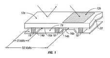
- FIG. 1is an isometric view depicting a portion of one embodiment of an interferometric modulator display in which a movable reflective layer of a first interferometric modulator is in a relaxed position and a movable reflective layer of a second interferometric modulator is in an actuated position.
- FIG. 2is a system block diagram illustrating one embodiment of an electronic device incorporating a 3 ⁇ 3 interferometric modulator display.
- FIG. 3is a diagram of movable mirror position versus applied voltage for one exemplary embodiment of an interferometric modulator of FIG. 1 .
- FIG. 4is an illustration of a set of row and column voltages that may be used to drive an interferometric modulator display.
- FIGS. 5A and 5Billustrate one exemplary timing diagram for row and column signals that may be used to write a frame of display data to the 3 ⁇ 3 interferometric modulator display of FIG. 2 .
- FIGS. 6A and 6Bare system block diagrams illustrating an embodiment of a visual display device comprising a plurality of interferometric modulators.
- FIG. 7Ais a cross section of the device of FIG. 1 .
- FIG. 7Bis a cross section of an alternative embodiment of an interferometric modulator.
- FIG. 7Cis a cross section of another alternative embodiment of an interferometric modulator.
- FIG. 7Dis a cross section of yet another alternative embodiment of an interferometric modulator.
- FIG. 7Eis a cross section of an additional alternative embodiment of an interferometric modulator.
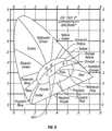
- FIG. 8is a chromaticity diagram illustrating the effects of combining colors to generate white.
- FIG. 9is a chromaticity diagram illustrating a method for selecting colors that when combined generate another color.
- FIG. 10is a flowchart describing an exemplary method for selecting a two color array of MEMS devices that generates the color white.
- FIG. 11is a diagram illustrating an exemplary array of two MEMS devices with optical responses selected in accordance with the flowchart of FIG. 10 .
- Interferometric modulatorscan be arranged in arrays to produce a color display. Generation of the color white in a display can also be accomplished.
- the color whitemay be generated through the combination of two interferometric modulators types, each capable of reflecting light at a wavelength complementary to the other. By combining the reflected light from the two modulator types, the resulting light appears to have the color white.
- an arraymay comprise a first plurality of color interferometric modulators. Each modulator in the first plurality may reflect a first color light.
- the arraymay further comprise a second plurality of color interferometric modulators configured to reflect a second color light. The reflected light from the first plurality of color interferometric modulators and the second plurality of color interferometric modulators, when combined together, appear substantially white.
- the embodimentsmay be implemented in or associated with a variety of electronic devices such as, but not limited to, mobile telephones, wireless devices, personal data assistants (PDAs), hand-held or portable computers, GPS receivers/navigators, cameras, MP3 players, camcorders, game consoles, wrist watches, clocks, calculators, television monitors, flat panel displays, computer monitors, auto displays (e.g., odometer display, etc.), cockpit controls and/or displays, display of camera views (e.g., display of a rear view camera in a vehicle), electronic photographs, electronic billboards or signs, projectors, architectural structures, packaging, and aesthetic structures (e.g., display of images on a piece of jewelry).
- MEMS devices of similar structure to those described hereincan also be used in non-display applications such as in electronic switching devices.
- a displaywill comprise a plurality of the first type of interferometric modulator and a second plurality of the second type of interferometric modulator. Such a display may reflect light having a first wavelength according to the first type of interferometric modulator, light having a second wavelength according to the second type of interferometric modulator, and light having the wavelength of the color white.
- FIG. 1One interferometric modulator display embodiment comprising an interferometric MEMS display element is illustrated in FIG. 1 .
- the pixelsare in either a bright or dark state.
- the display elementIn the bright (“on” or “open”) state, the display element reflects a large portion of incident visible light to a user.
- the dark (“off” or “closed”) stateWhen in the dark (“off” or “closed”) state, the display element reflects little incident visible light to the user.
- the light reflectance properties of the “on” and “off” statesmay be reversed.
- MEMS pixelscan be configured to reflect predominantly at selected colors, allowing for a color display in addition to black and white.
- FIG. 1is an isometric view depicting two adjacent pixels in a series of pixels of a visual display, wherein each pixel comprises a MEMS interferometric modulator.
- an interferometric modulator displaycomprises a row/column array of these interferometric modulators.
- Each interferometric modulatorincludes a pair of reflective layers positioned at a variable and controllable distance from each other to form a resonant optical cavity with at least one variable dimension.
- one of the reflective layersmay be moved between two positions. In the first position, referred to herein as the relaxed position, the movable reflective layer is positioned at a relatively large distance from a fixed partially reflective layer.
- the movable reflective layerIn the second position, referred to herein as the actuated position, the movable reflective layer is positioned more closely adjacent to the partially reflective layer. Incident light that reflects from the two layers interferes constructively or destructively depending on the position of the movable reflective layer, producing either an overall reflective or non-reflective state for each pixel.
- the depicted portion of the pixel array in FIG. 1includes two adjacent interferometric modulators 12 a and 12 b .
- a movable reflective layer 14 ais illustrated in a relaxed position at a predetermined distance from an optical stack 16 a , which includes a partially reflective layer.
- the movable reflective layer 14 bis illustrated in an actuated position adjacent to the optical stack 16 b .
- the depicted portion of the pixel array in FIG. 1includes two adjacent interferometric modulators 12 a and 12 b .
- a movable reflective layer 14 ais illustrated in a relaxed position at a predetermined distance from an optical stack 16 a , which includes a partially reflective layer.
- the movable reflective layer 14 bis illustrated in an actuated position adjacent to the optical stack 16 b.
- optical stack 16typically comprise of several fused layers, which can include an electrode layer, such as indium tin oxide (ITO), a partially reflective layer, such as chromium, and a transparent dielectric.
- ITOindium tin oxide
- the optical stack 16is thus electrically conductive, partially transparent and partially reflective, and may be fabricated, for example, by depositing one or more of the above layers onto a transparent substrate 20 .
- the layersare patterned into parallel strips, and may form row electrodes in a display device as described further below.
- the movable reflective layers 14 a , 14 bmay be formed as a series of parallel strips of a deposited metal layer or layers (orthogonal to the row electrodes of 16 a , 16 b ) deposited on top of posts 18 and an intervening sacrificial material deposited between the posts 18 . When the sacrificial material is etched away, the movable reflective layers 14 a , 14 b are separated from the optical stacks 16 a , 16 b by a defined gap 19 .
- a highly conductive and reflective materialsuch as aluminum may be used for the reflective layers 14 , and these strips may form column electrodes in a display device.
- the cavity 19remains between the movable reflective layer 14 a and optical stack 16 a , with the movable reflective layer 14 a in a mechanically relaxed state, as illustrated by the pixel 12 a in FIG. 1 .
- a potential differenceis applied to a selected row and column, the capacitor formed at the intersection of the row and column electrodes at the corresponding pixel becomes charged, and electrostatic forces pull the electrodes together.
- the movable reflective layer 14is deformed and is forced against the optical stack 16 .
- a dielectric layerwithin the optical stack 16 may prevent shorting and control the separation distance between layers 14 and 16 , as illustrated by pixel 12 b on the right in FIG. 1 .
- the behavioris the same regardless of the polarity of the applied potential difference. In this way, row/column actuation that can control the reflective vs. non-reflective pixel states is analogous in many ways to that used in conventional LCD and other display technologies.
- FIGS. 2 through 5illustrate one exemplary process and system for using an array of interferometric modulators in a display application.
- FIG. 2is a system block diagram illustrating one embodiment of an electronic device that may incorporate aspects of the invention.
- the electronic deviceincludes a processor 21 which may be any general purpose single- or multi-chip microprocessor such as an ARM, Pentium®, Pentium II®, Pentium III®, Pentium IV, Pentium® Pro, an 8051, a MIPS®, a Power PC®, an ALPHA®, or any special purpose microprocessor such as a digital signal processor, microcontroller, or a programmable gate array.
- the processor 21may be configured to execute one or more software modules.
- the processormay be configured to execute one or more software applications, including a web browser, a telephone application, an email program, or any other software application.
- the processor 21is also configured to communicate with an array driver 22 .
- the array driver 22includes a row driver circuit 24 and a column driver circuit 26 that provide signals to a panel or display array (display) 30 .
- the cross section of the array illustrated in FIG. 1is shown by the lines 1 - 1 in FIG. 2 .
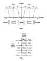
- the row/column actuation protocolmay take advantage of a hysteresis property of these devices illustrated in FIG. 3 . It may require, for example, a 10 volt potential difference to cause a movable layer to deform from the relaxed state to the actuated state.
- the movable layermaintains its state as the voltage drops back below 10 volts.
- the movable layerdoes not relax completely until the voltage drops below 2 volts.
- There is thus a range of voltage, about 3 to 7 V in the example illustrated in FIG. 3where there exists a window of applied voltage within which the device is stable in either the relaxed or actuated state. This is referred to herein as the “hysteresis window” or “stability window.”
- the row/column actuation protocolcan be designed such that during row strobing, pixels in the strobed row that are to be actuated are exposed to a voltage difference of about 10 volts, and pixels that are to be relaxed are exposed to a voltage difference of close to zero volts. After the strobe, the pixels are exposed to a steady state voltage difference of about 5 volts such that they remain in whatever state the row strobe put them in. After being written, each pixel sees a potential difference within the “stability window” of 3-7 volts in this example. This feature makes the pixel design illustrated in FIG. 1 stable under the same applied voltage conditions in either an actuated or relaxed pre-existing state.
- each pixel of the interferometric modulatoris essentially a capacitor formed by the fixed and moving reflective layers, this stable state can be held at a voltage within the hysteresis window with almost no power dissipation. Essentially no current flows into the pixel if the applied potential is fixed.
- a display framemay be created by asserting the set of column electrodes in accordance with the desired set of actuated pixels in the first row.
- a row pulseis then applied to the row 1 electrode, actuating the pixels corresponding to the asserted column lines.
- the asserted set of column electrodesis then changed to correspond to the desired set of actuated pixels in the second row.
- a pulseis then applied to the row 2 electrode, actuating the appropriate pixels in row 2 in accordance with the asserted column electrodes.
- the row 1 pixelsare unaffected by the row 2 pulse, and remain in the state they were set to during the row 1 pulse. This may be repeated for the entire series of rows in a sequential fashion to produce the frame.
- the framesare refreshed and/or updated with new display data by continually repeating this process at some desired number of frames per second.
- protocols for driving row and column electrodes of pixel arrays to produce display framesare also well known and may be used in conjunction with the present invention.
- FIGS. 4 and 5illustrate one possible actuation protocol for creating a display frame on the 3 ⁇ 3 array of FIG. 2 .
- FIG. 4illustrates a possible set of column and row voltage levels that may be used for pixels exhibiting the hysteresis curves of FIG. 3 .
- actuating a pixelinvolves setting the appropriate column to ⁇ V bias , and the appropriate row to + ⁇ V, which may correspond to ⁇ 5 volts and +5 volts respectively Relaxing the pixel is accomplished by setting the appropriate column to +V bias , and the appropriate row to the same + ⁇ V, producing a zero volt potential difference across the pixel.
- the pixelsare stable in whatever state they were originally in, regardless of whether the column is at +V bias , or ⁇ V bias .
- voltages of opposite polarity than those described abovecan be used, e.g., actuating a pixel can involve setting the appropriate column to +V bias , and the appropriate row to ⁇ V.
- releasing the pixelis accomplished by setting the appropriate column to ⁇ V bias , and the appropriate row to the same ⁇ V, producing a zero volt potential difference across the pixel.
- FIG. 5Bis a timing diagram showing a series of row and column signals applied to the 3 ⁇ 3 array of FIG. 2 which will result in the display arrangement illustrated in FIG. 5A , where actuated pixels are non-reflective.
- the pixelsPrior to writing the frame illustrated in FIG. 5A , the pixels can be in any state, and in this example, all the rows are at 0 volts, and all the columns are at +5 volts. With these applied voltages, all pixels are stable in their existing actuated or relaxed states.
- pixels (1,1), (1,2), (2,2), (3,2) and (3,3)are actuated.
- columns 1 and 2are set to ⁇ 5 volts, and column 3 is set to +5 volts. This does not change the state of any pixels, because all the pixels remain in the 3-7 volt stability window.
- Row 1is then strobed with a pulse that goes from 0, up to 5 volts, and back to zero. This actuates the (1,1) and (1,2) pixels and relaxes the (1,3) pixel. No other pixels in the array are affected.
- column 2is set to ⁇ 5 volts
- columns 1 and 3are set to +5 volts.
- Row 3is similarly set by setting columns 2 and 3 to ⁇ 5 volts, and column 1 to +5 volts.
- the row 3 strobesets the row 3 pixels as shown in FIG. 5A .
- the row potentialsare zero, and the column potentials can remain at either +5 or ⁇ 5 volts, and the display is then stable in the arrangement of FIG. 5A . It will be appreciated that the same procedure can be employed for arrays of dozens or hundreds of rows and columns.
- FIGS. 6A and 6Bare system block diagrams illustrating an embodiment of a display device 40 .
- the display device 40can be, for example, a cellular or mobile telephone.
- the same components of display device 40 or slight variations thereofare also illustrative of various types of display devices such as televisions and portable media players.
- the display device 40includes a housing 41 , a display 30 , an antenna 43 , a speaker 45 , an input device 48 , and a microphone 46 .
- the housing 41is generally formed from any of a variety of manufacturing processes as are well known to those of skill in the art, including injection molding, and vacuum forming.
- the housing 41may be made from any of a variety of materials, including but not limited to plastic, metal, glass, rubber, and ceramic, or a combination thereof.
- the housing 41includes removable portions (not shown) that may be interchanged with other removable portions of different color, or containing different logos, pictures, or symbols.
- the display 30 of exemplary display device 40may be any of a variety of displays, including a bi-stable display, as described herein.
- the display 30includes a flat-panel display, such as plasma, EL, OLED, STN LCD, or TFT LCD as described above, or a non-flat-panel display, such as a CRT or other tube device, as is well known to those of skill in the art.
- the display 30includes an interferometric modulator display, as described herein.
- the components of one embodiment of exemplary display device 40are schematically illustrated in FIG. 6B .
- the illustrated exemplary display device 40includes a housing 41 and can include additional components at least partially enclosed therein.
- the exemplary display device 40includes a network interface 27 that includes an antenna 43 which is coupled to a transceiver 47 .
- the transceiver 47is connected to the processor 21 , which is connected to conditioning hardware 52 .
- the conditioning hardware 52may be configured to condition a signal (e.g. filter a signal).
- the conditioning hardware 52is connected to a speaker 45 and a microphone 46 .
- the processor 21is also connected to an input device 48 and a driver controller 29 .
- the driver controller 29is coupled to a frame buffer 28 and to the array driver 22 , which in turn is coupled to a display array 30 .
- a power supply 50provides power to all components as required by the particular exemplary display device 40 design.
- the network interface 27includes the antenna 43 and the transceiver 47 so that the exemplary display device 40 can communicate with one or more devices over a network. In one embodiment the network interface 27 may also have some processing capabilities to relieve requirements of the processor 21 .
- the antenna 43is any antenna known to those of skill in the art for transmitting and receiving signals. In one embodiment, the antenna transmits and receives RF signals according to the IEEE 802.11 standard, including IEEE 802.11(a), (b), or (g). In another embodiment, the antenna transmits and receives RF signals according to the BLUETOOTH standard. In the case of a cellular telephone, the antenna is designed to receive CDMA, GSM, AMPS or other known signals that are used to communicate within a wireless cell phone network.
- the transceiver 47pre-processes the signals received from the antenna 43 so that they may be received by and further manipulated by the processor 21 .
- the transceiver 47also processes signals received from the processor 21 so that they may be transmitted from the exemplary display device 40 via the antenna 43 .
- the transceiver 47can be replaced by a receiver.
- network interface 27can be replaced by an image source, which can store or generate image data to be sent to the processor 21 .
- the image sourcecan be a digital video disc (DVD) or a hard-disc drive that contains image data, or a software module that generates image data.
- Processor 21generally controls the overall operation of the exemplary display device 40 .
- the processor 21receives data, such as compressed image data from the network interface 27 or an image source, and processes the data into raw image data or into a format that is readily processed into raw image data.
- the processor 21then sends the processed data to the driver controller 29 or to frame buffer 28 for storage.
- Raw datatypically refers to the information that identifies the image characteristics at each location within an image. For example, such image characteristics can include color, saturation, and gray-scale level.
- the processor 21includes a microcontroller, CPU, or logic unit to control operation of the exemplary display device 40 .
- Conditioning hardware 52generally includes amplifiers and filters for transmitting signals to the speaker 45 , and for receiving signals from the microphone 46 .
- Conditioning hardware 52may be discrete components within the exemplary display device 40 , or may be incorporated within the processor 21 or other components.
- the driver controller 29takes the raw image data generated by the processor 21 either directly from the processor 21 or from the frame buffer 28 and reformats the raw image data appropriately for high speed transmission to the array driver 22 . Specifically, the driver controller 29 reformats the raw image data into a data flow having a raster-like format, such that it has a time order suitable for scanning across the display array 30 . Then the driver controller 29 sends the formatted information to the array driver 22 .
- a driver controller 29such as a LCD controller, is often associated with the system processor 21 as a stand-alone Integrated Circuit (IC), such controllers may be implemented in many ways. They may be embedded in the processor 21 as hardware, embedded in the processor 21 as software, or fully integrated in hardware with the array driver 22 .
- the array driver 22receives the formatted information from the driver controller 29 and reformats the video data into a parallel set of waveforms that are applied many times per second to the hundreds and sometimes thousands of leads coming from the display's x-y matrix of pixels.
- driver controller 29is a conventional display controller or a bi-stable display controller (e.g., an interferometric modulator controller).
- array driver 22is a conventional driver or a bi-stable display driver (e.g., an interferometric modulator display).
- a driver controller 29is integrated with the array driver 22 .
- display array 30is a typical display array or a bi-stable display array (e.g., a display including an array of interferometric modulators).
- the input device 48allows a user to control the operation of the exemplary display device 40 .
- input device 48includes a keypad, such as a QWERTY keyboard or a telephone keypad, a button, a switch, a touch-sensitive screen, a pressure- or heat-sensitive membrane.
- the microphone 46is an input device for the exemplary display device 40 . When the microphone 46 is used to input data to the device, voice commands may be provided by a user for controlling operations of the exemplary display device 40 .
- Power supply 50can include a variety of energy storage devices as are well known in the art.
- power supply 50is a rechargeable battery, such as a nickel-cadmium battery or a lithium ion battery.
- power supply 50is a renewable energy source, a capacitor, or a solar cell, including a plastic solar cell, and solar-cell paint.
- power supply 50is configured to receive power from a wall outlet.
- control programmabilityresides, as described above, in a driver controller which can be located in several places in the electronic display system. In some cases control programmability resides in the array driver 22 . Those of skill in the art will recognize that the above-described optimization may be implemented in any number of hardware and/or software components and in various configurations.
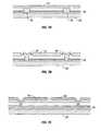
- FIGS. 7A-7Eillustrate five different embodiments of the movable reflective layer 14 and its supporting structures.
- FIG. 7Ais a cross section of the embodiment of FIG. 1 , where a strip of metal material 14 is deposited on orthogonally extending supports 18 .
- FIG. 7Bthe moveable reflective layer 14 is attached to supports at the corners only, on tethers 32 .
- FIG. 7Cthe moveable reflective layer 14 is suspended from a deformable layer 34 , which may comprise a flexible metal.
- the deformable layer 34connects, directly or indirectly, to the substrate 20 around the perimeter of the deformable layer 34 .
- connection postsare herein referred to as support posts.
- the embodiment illustrated in FIG. 7Dhas support post plugs 42 upon which the deformable layer 34 rests.
- the movable reflective layer 14remains suspended over the cavity, as in FIGS. 7A-7C , but the deformable layer 34 does not form the support posts by filling holes between the deformable layer 34 and the optical stack 16 . Rather, the support posts are formed of a planarization material, which is used to form support post plugs 42 .
- the embodiment illustrated in FIG. 7Eis based on the embodiment shown in FIG. 7D , but may also be adapted to work with any of the embodiments illustrated in FIGS. 7A-7C as well as additional embodiments not shown. In the embodiment shown in FIG. 7E , an extra layer of metal or other conductive material has been used to form a bus structure 44 . This allows signal routing along the back of the interferometric modulators, eliminating a number of electrodes that may otherwise have had to be formed on the substrate 20 .
- the interferometric modulatorsfunction as direct-view devices, in which images are viewed from the front side of the transparent substrate 20 , the side opposite to that upon which the modulator is arranged.
- the reflective layer 14optically shields some portions of the interferometric modulator on the side of the reflective layer opposite the substrate 20 , including the deformable layer 34 and the bus structure 44 . This allows the shielded areas to be configured and operated upon without negatively affecting the image quality.
- This separable modulator architectureallows the structural design and materials used for the electromechanical aspects and the optical aspects of the modulator to be selected and to function independently of each other.
- Various embodiments of display devices described hereincan accurately reproduce light of any color.
- the color of light at a single wavelengthis said to be a monochromatic color.
- the generation of an arbitrary colorcan be accomplished by having a monochromatic light source with exactly that wavelength.
- the same arbitrary colormay be perceived by a viewer when the light from two or more different monochromatic sources at different intensities are combined.
- Mixing different sets of light wavelengthscan sometimes produce the same or substantially the same resulting perceived color effect. For example, mixing blue and yellow light of equal intensity produces light appearing to have a white color; as does mixing red and blue-green light. These combinations have different spectral distributions, but the perceived result appears the same. Any two colors that mix with the proper intensities to produce the color white are said to be complementary.
- the CIE systemprovides a curved line 800 that starts in the orange section of the diagram and extends to the left and downward until it ends in the desaturated part of the blue region.
- This line 800represents the color temperatures of the ideal blackbody radiator. It is sometimes called the blackbody or Planckian locus.
- a blackbody radiatoris a theoretical object that absorbs 100% of the radiation incident thereon while being able to emit the maximum amount of energy possible for a particular temperature.
- Certain points along the Planckian locusare labeled with the corresponding color temperature in Kelvin. As may be seen, if a blackbody is heated to 1900 K, it glows orange. As the temperature increases, the color of the radiated light moves to yellow, then white, and finally to blue.
- Point Ais defined as the color of a blackbody radiator at 2856 K.
- the other pointsrepresent various correlated color temperatures.
- point Drepresents a correlated color temperature of 6500 K and is often referred to as D6500 or D65.
- Light that is on or close to the reference illuminants or pale in hue saturationis considered to be substantially white.
- FIG. 9is a chromaticity diagram illustrating a method for selecting colors that when combined are perceived as another color. While the two colors selected for this example are not complementary in that the colors, when combined, do not generate white, the example is instructive in creating embodiments having complementary colors.
- any two pointsare selected on the chromaticity chart, for example, of FIG. 9 .
- the selected pointsmay be located on the outer spectrum locus or within the chromaticity chart.
- the color corresponding to each of the selected pointsmay or may not be monochromatic.
- point 903 corresponding to 600 nm (reddish orange) and point 901 corresponding to 510 nm (green)are selected.
- a straight lineis then drawn between the two selected points.
- line 905is drawn between points 901 , 903 .
- line 905passes through several hue regions. Mixing different intensities of light at 600 nm, point 903 , and 510 nm, point 901 , can generate any color through which line 905 passes.
- orange, orange-yellow, yellow, yellow-green, and yellowish greencan be generated in addition to the end points 903 , 901 of reddish orange and green, respectively.
- any two points or colors connected by a line that passes through white region 907can be combined in suitable proportions to generate the color white.
- Examplesare well known in the art whereby pairs of monochromatic complementary light are combined to generate a color corresponding to a specific reference illuminant white. See Color Science Concepts and Methods, Quantitative Data and Formulae , G. Wyszecki and W. S. Stiles (Wiley-Interscience 2000).
- the CIE reference illuminant D65can be generated by pairing one monochromatic light at a wavelength (w 1 ) of 480 nm with a second monochromatic light (w 2 ) at a wavelength of 578 nm in a radiant power ratio (P w1 /P w2 ) of 0.642.
- the same D65can be generated by pairing one monochromatic light at a wavelength of 680 nm with a second monochromatic light at a wavelength of 493.3 nm in a radiant power ratio of 0.147.
- Two colorsare substantially complementary to each other when the resulting color white is on or close to the reference illuminants or substantially pale in hue saturation.
- An interferometric modulator 12 a(see FIG. 1 ) is designed to reflect light at a specific predetermined wavelength depending upon the material and geometry of the modulator as discussed above. As illustrated in FIG. 5A , an array of interferometric modulators 12 a or pixels (1,1), (1,2), (2,2), (3,2) and (3,3) may be placed together to form a display.
- At least a portion of the displaycomprises an array of interferometric modulators 12 a .
- the arrayis comprised of at least two interferometric modulator 12 a types.
- Each type of interferometric modulator 12 ais capable of displaying a monochromatic color, for example, with its cavity open, or black, when in an actuated state with its cavity closed.
- the wavelength of light reflected by the first modulator typeis selected to be complementary to the wavelength of light reflected by the second modulator type.
- a given interferometric modulator 12 amay not reflect light at precisely the single wavelength it was designed to reflect. Instead, a given interferometric modulator 12 a may reflect a range of wavelengths of light around the design wavelength. In certain embodiments, the perceived color is substantially white, so long as the center wavelengths of light from the two types of interferometric modulator types are complementary or substantially complementary to each other.
- the reflected light of the two complementary wavelengthsare reflected in the appropriate intensities.
- varying the intensity of each light coloris achieved by increasing or decreasing the surface areas of the display that correspond to the two interferometric modulator types.
- the intensity of the light color of the first modulator typecan be increased relative to the intensity of the second modulator type by having a greater number of first modulator types or by having modulators with larger reflective area than the second modulator type.
- varying the intensity of each light coloris achieved by variable pulse width activation of the modulators, whereby the duration of the pulse is in proportion to the intensity desired.
- the intensity of the light color of the first modulator typecan be increased relative to the intensity of the second modulator type by keeping the first modulator type in an open, reflective state longer than the second modulator type.
- the desired relative intensitiesis obtained.
- both variable pulsed width actuation and variable surface areasare used in combination to achieve the desired relative intensities.
- filterssuch as, e.g. neutral density and color filters, may also be used to attenuate and/or control the reflected intensities.
- traditional colorssuch as red, blue, or green need not be selected for one or both of the two types of interferometric modulators to create white.
- the colors chosencan be non-traditional color, that is, colors which are generally not chosen for their ease to create a wide gamut of other colors.
- combining the correct intensities of monochromatic purplish-blue light (light at a wavelength in the region close to around 470-490 nm) with monochromatic greenish-yellow light (light at a wavelength in the region close to around 570-600 nm)can produce light with the color white. This is useful as complementary colors created from non-traditional colors may be easier to generate or manipulate than traditional colors.
- the cost of the displaycan be reduced through a reduction in the number of processing and mask steps.
- a display having fewer types of interferometric modulatorsis less costly to manufacture than displays having three or more types of interferometric modulators.
- an apparatus and method of fabrication as described abovemay be employed once the materials and geometries for the two types of interferometric modulators are selected based on their combined capacity to generate the color white.
- FIG. 10is a flowchart 100 describing a methodology for determining the materials and dimensions of the two types of interferometric modulators 12 a in an array of interferometric modulators.
- the processbegins at block 502 where a candidate color for the first modulator type is selected. This selection may, for example, be based on the monochrome aspects of that color as far as ability to be viewed under different environmental conditions, on its mixing properties with other colors, and on the efficiency by which it is actuated.
- the second coloris determined. This second color is preferably complimentary to the color of the first modulator type selected at block 502 . This step can be illustrated with reference back to FIG. 9 .
- the candidate for the first coloris selected to be the color represent by point 903 in the chromaticity diagram, which corresponds to light having a wavelength of roughly 605 nm.
- the second coloris determined to be at the wavelength found at point 909 .
- point 909corresponds to light having a wavelength of roughly 500 nm.
- the candidate second colorcan be determined with reference to tables of known complementary color pairs.
- the design choiceis evaluated. It may be found that this combination of colors is not acceptable. The combination may not be acceptable if, for example, the display must reflect some form of monochromatic green which is not capable of being generated with either one of the two colors corresponding to points 903 , 909 in FIG. 9 . A combination may also be found unacceptable due to difficulty in manufacturing one or more of the two types of interferometric modulators. The activation voltage associated with the second type of interferometric modulator may also render the color selection at block 504 unacceptable. At block 506 , an alternative second color can be used to correct the deficiency.
- the methoddetermines if the second color satisfies the design requirements. If the second color does not satisfy the design requirements and an alternative second color does not satisfy the design requirements, the process moves to block 510 where a new color is selected for the first modulator type. This color may be similar to or different than the originally chosen first color. The process then moves to the block 504 and continues as described above. The process repeats until an acceptable design is achieved and the design is accepted in block 512 .
- FIG. 11illustrates an exemplary two modulator display device 1100 having a first interferometric modulator type 1104 and a second interferometric modulator type 1102 .
- the design of the optical stack 16 and movable reflective layer 14are as described above.
- the movable reflective layers 14are separated from the optical stacks 16 by a defined gap 19 a , 19 b .
- the gaps 19 a , 19 b in conjunction with optical stacks 16determine the optical response of each interferometric modulator 1102 , 1104 .
- the distance of the gaps 19 a , 19 bare selected to provide wavelengths of light complementary to each other.
- the arrayBy designing the array to comprise interferometric modulators that reflect two colors and by restricting those colors to be complementary, a low cost display with white display capability is provided.
Landscapes
- Physics & Mathematics (AREA)
- Spectroscopy & Molecular Physics (AREA)
- General Physics & Mathematics (AREA)
- Optics & Photonics (AREA)
- Mechanical Light Control Or Optical Switches (AREA)
Abstract
Description
Claims (21)
Priority Applications (1)
| Application Number | Priority Date | Filing Date | Title |
|---|---|---|---|
| US12/427,670US8098431B2 (en) | 2004-09-27 | 2009-04-21 | Method and device for generating white in an interferometric modulator display |
Applications Claiming Priority (3)
| Application Number | Priority Date | Filing Date | Title |
|---|---|---|---|
| US61350404P | 2004-09-27 | 2004-09-27 | |
| US11/188,197US7525730B2 (en) | 2004-09-27 | 2005-07-22 | Method and device for generating white in an interferometric modulator display |
| US12/427,670US8098431B2 (en) | 2004-09-27 | 2009-04-21 | Method and device for generating white in an interferometric modulator display |
Related Parent Applications (1)
| Application Number | Title | Priority Date | Filing Date |
|---|---|---|---|
| US11/188,197ContinuationUS7525730B2 (en) | 2004-09-27 | 2005-07-22 | Method and device for generating white in an interferometric modulator display |
Publications (2)
| Publication Number | Publication Date |
|---|---|
| US20090296191A1 US20090296191A1 (en) | 2009-12-03 |
| US8098431B2true US8098431B2 (en) | 2012-01-17 |
Family
ID=35432146
Family Applications (2)
| Application Number | Title | Priority Date | Filing Date |
|---|---|---|---|
| US11/188,197Expired - Fee RelatedUS7525730B2 (en) | 2004-09-27 | 2005-07-22 | Method and device for generating white in an interferometric modulator display |
| US12/427,670Expired - Fee RelatedUS8098431B2 (en) | 2004-09-27 | 2009-04-21 | Method and device for generating white in an interferometric modulator display |
Family Applications Before (1)
| Application Number | Title | Priority Date | Filing Date |
|---|---|---|---|
| US11/188,197Expired - Fee RelatedUS7525730B2 (en) | 2004-09-27 | 2005-07-22 | Method and device for generating white in an interferometric modulator display |
Country Status (7)
| Country | Link |
|---|---|
| US (2) | US7525730B2 (en) |
| EP (1) | EP1800161A1 (en) |
| AU (1) | AU2005290107A1 (en) |
| BR (1) | BRPI0515901A (en) |
| IL (1) | IL181037A0 (en) |
| TW (1) | TW200624861A (en) |
| WO (1) | WO2006036421A1 (en) |
Families Citing this family (50)
| Publication number | Priority date | Publication date | Assignee | Title |
|---|---|---|---|---|
| WO2003007049A1 (en) | 1999-10-05 | 2003-01-23 | Iridigm Display Corporation | Photonic mems and structures |
| US7417782B2 (en) | 2005-02-23 | 2008-08-26 | Pixtronix, Incorporated | Methods and apparatus for spatial light modulation |
| US7710632B2 (en) | 2004-09-27 | 2010-05-04 | Qualcomm Mems Technologies, Inc. | Display device having an array of spatial light modulators with integrated color filters |
| US20060066557A1 (en)* | 2004-09-27 | 2006-03-30 | Floyd Philip D | Method and device for reflective display with time sequential color illumination |
| US7525730B2 (en) | 2004-09-27 | 2009-04-28 | Idc, Llc | Method and device for generating white in an interferometric modulator display |
| US7911428B2 (en) | 2004-09-27 | 2011-03-22 | Qualcomm Mems Technologies, Inc. | Method and device for manipulating color in a display |
| US8031133B2 (en)* | 2004-09-27 | 2011-10-04 | Qualcomm Mems Technologies, Inc. | Method and device for manipulating color in a display |
| US20060077148A1 (en)* | 2004-09-27 | 2006-04-13 | Gally Brian J | Method and device for manipulating color in a display |
| US7813026B2 (en) | 2004-09-27 | 2010-10-12 | Qualcomm Mems Technologies, Inc. | System and method of reducing color shift in a display |
| US8362987B2 (en)* | 2004-09-27 | 2013-01-29 | Qualcomm Mems Technologies, Inc. | Method and device for manipulating color in a display |
| US8102407B2 (en)* | 2004-09-27 | 2012-01-24 | Qualcomm Mems Technologies, Inc. | Method and device for manipulating color in a display |
| US7304786B2 (en) | 2005-02-23 | 2007-12-04 | Pixtronix, Inc. | Methods and apparatus for bi-stable actuation of displays |
| US9082353B2 (en) | 2010-01-05 | 2015-07-14 | Pixtronix, Inc. | Circuits for controlling display apparatus |
| US7405852B2 (en) | 2005-02-23 | 2008-07-29 | Pixtronix, Inc. | Display apparatus and methods for manufacture thereof |
| US8519945B2 (en) | 2006-01-06 | 2013-08-27 | Pixtronix, Inc. | Circuits for controlling display apparatus |
| US20070205969A1 (en) | 2005-02-23 | 2007-09-06 | Pixtronix, Incorporated | Direct-view MEMS display devices and methods for generating images thereon |
| US9229222B2 (en) | 2005-02-23 | 2016-01-05 | Pixtronix, Inc. | Alignment methods in fluid-filled MEMS displays |
| US9261694B2 (en) | 2005-02-23 | 2016-02-16 | Pixtronix, Inc. | Display apparatus and methods for manufacture thereof |
| US7999994B2 (en) | 2005-02-23 | 2011-08-16 | Pixtronix, Inc. | Display apparatus and methods for manufacture thereof |
| US9158106B2 (en) | 2005-02-23 | 2015-10-13 | Pixtronix, Inc. | Display methods and apparatus |
| US7746529B2 (en) | 2005-02-23 | 2010-06-29 | Pixtronix, Inc. | MEMS display apparatus |
| US7304785B2 (en) | 2005-02-23 | 2007-12-04 | Pixtronix, Inc. | Display methods and apparatus |
| US8482496B2 (en) | 2006-01-06 | 2013-07-09 | Pixtronix, Inc. | Circuits for controlling MEMS display apparatus on a transparent substrate |
| US8159428B2 (en) | 2005-02-23 | 2012-04-17 | Pixtronix, Inc. | Display methods and apparatus |
| US8310442B2 (en) | 2005-02-23 | 2012-11-13 | Pixtronix, Inc. | Circuits for controlling display apparatus |
| US9087486B2 (en) | 2005-02-23 | 2015-07-21 | Pixtronix, Inc. | Circuits for controlling display apparatus |
| US8526096B2 (en) | 2006-02-23 | 2013-09-03 | Pixtronix, Inc. | Mechanical light modulators with stressed beams |
| US8004743B2 (en) | 2006-04-21 | 2011-08-23 | Qualcomm Mems Technologies, Inc. | Method and apparatus for providing brightness control in an interferometric modulator (IMOD) display |
| US7876489B2 (en) | 2006-06-05 | 2011-01-25 | Pixtronix, Inc. | Display apparatus with optical cavities |
| EP2080045A1 (en) | 2006-10-20 | 2009-07-22 | Pixtronix Inc. | Light guides and backlight systems incorporating light redirectors at varying densities |
| US20080111834A1 (en)* | 2006-11-09 | 2008-05-15 | Mignard Marc M | Two primary color display |
| US7852546B2 (en) | 2007-10-19 | 2010-12-14 | Pixtronix, Inc. | Spacers for maintaining display apparatus alignment |
| US9176318B2 (en) | 2007-05-18 | 2015-11-03 | Pixtronix, Inc. | Methods for manufacturing fluid-filled MEMS displays |
| JP5029187B2 (en)* | 2007-07-20 | 2012-09-19 | 株式会社ニコン | Color coordinate conversion device, imaging device, color coordinate conversion program, and color coordinate conversion method |
| WO2009102620A2 (en)* | 2008-02-11 | 2009-08-20 | Qualcomm Mems Technologies Inc. | Methods for measurement and characterization of interferometric modulators |
| EP2252991A1 (en)* | 2008-02-11 | 2010-11-24 | QUALCOMM MEMS Technologies, Inc. | Method and apparatus for sensing, measurement or characterization of display elements integrated with the display drive scheme, and system and applications using the same |
| US20090201282A1 (en)* | 2008-02-11 | 2009-08-13 | Qualcomm Mems Technologies, Inc | Methods of tuning interferometric modulator displays |
| US8395371B2 (en)* | 2008-02-11 | 2013-03-12 | Qualcomm Mems Technologies, Inc. | Methods for characterizing the behavior of microelectromechanical system devices |
| US8466858B2 (en)* | 2008-02-11 | 2013-06-18 | Qualcomm Mems Technologies, Inc. | Sensing to determine pixel state in a passively addressed display array |
| US9331513B2 (en)* | 2008-04-11 | 2016-05-03 | Apple Inc. | Adaptive surface concentration battery charging |
| US8248560B2 (en) | 2008-04-18 | 2012-08-21 | Pixtronix, Inc. | Light guides and backlight systems incorporating prismatic structures and light redirectors |
| US8169679B2 (en) | 2008-10-27 | 2012-05-01 | Pixtronix, Inc. | MEMS anchors |
| KR20120132680A (en) | 2010-02-02 | 2012-12-07 | 픽스트로닉스 인코포레이티드 | Methods for manufacturing cold seal fluid-filled display apparatus |
| MX2012012033A (en) | 2010-04-16 | 2013-05-20 | Flex Lighting Ii Llc | Illumination device comprising a film-based lightguide. |
| EP2558893A4 (en) | 2010-04-16 | 2014-06-11 | Flex Lighting Ii Llc | TEACH COMPRISING A LIGHT GUIDE BASED ON A FILM |
| US8848294B2 (en) | 2010-05-20 | 2014-09-30 | Qualcomm Mems Technologies, Inc. | Method and structure capable of changing color saturation |
| US9324250B2 (en)* | 2011-09-09 | 2016-04-26 | Dolby Laboratories Licensing Corporation | High dynamic range displays comprising MEMS/IMOD components |
| TWI481474B (en)* | 2012-05-30 | 2015-04-21 | Choung Lii Chao | Glass processing methods |
| US9134552B2 (en) | 2013-03-13 | 2015-09-15 | Pixtronix, Inc. | Display apparatus with narrow gap electrostatic actuators |
| TWI569422B (en)* | 2014-08-01 | 2017-02-01 | 群創光電股份有限公司 | Display device and method for fabricating the same |
Citations (140)
| Publication number | Priority date | Publication date | Assignee | Title |
|---|---|---|---|---|
| US3448334A (en) | 1966-09-30 | 1969-06-03 | North American Rockwell | Multicolored e.l. displays using external colored light sources |
| US3725868A (en) | 1970-10-19 | 1973-04-03 | Burroughs Corp | Small reconfigurable processor for a variety of data processing applications |
| US4441791A (en) | 1980-09-02 | 1984-04-10 | Texas Instruments Incorporated | Deformable mirror light modulator |
| US4705361A (en) | 1985-11-27 | 1987-11-10 | Texas Instruments Incorporated | Spatial light modulator |
| US4822993A (en) | 1987-02-17 | 1989-04-18 | Optron Systems, Inc. | Low-cost, substantially cross-talk free high spatial resolution 2-D bistable light modulator |
| US4878741A (en) | 1986-09-10 | 1989-11-07 | Manchester R & D Partnership | Liquid crystal color display and method |
| EP0366181A2 (en) | 1988-10-26 | 1990-05-02 | Agfa-Gevaert N.V. | Silver sulphide sol with ultrafine particle size |
| US4929061A (en) | 1987-10-29 | 1990-05-29 | Kabushiki Kaisha Toshiba | Color liquid crystal display device |
| EP0389031A1 (en) | 1989-03-16 | 1990-09-26 | Koninklijke Philips Electronics N.V. | Colour display device |
| US5136669A (en) | 1991-03-15 | 1992-08-04 | Sperry Marine Inc. | Variable ratio fiber optic coupler optical signal processing element |
| US5142414A (en) | 1991-04-22 | 1992-08-25 | Koehler Dale R | Electrically actuatable temporal tristimulus-color device |
| US5168406A (en) | 1991-07-31 | 1992-12-01 | Texas Instruments Incorporated | Color deformable mirror device and method for manufacture |
| EP0330361B1 (en) | 1988-02-16 | 1993-04-21 | General Electric Company | Color display device |
| US5311360A (en) | 1992-04-28 | 1994-05-10 | The Board Of Trustees Of The Leland Stanford, Junior University | Method and apparatus for modulating a light beam |
| US5327263A (en) | 1989-12-18 | 1994-07-05 | Sharp Kabushiki Kaisha | Image processing apparatus employing a spatial light modulator |
| US5345322A (en) | 1985-03-01 | 1994-09-06 | Manchester R&D Limited Partnership | Complementary color liquid crystal display |
| US5452024A (en) | 1993-11-01 | 1995-09-19 | Texas Instruments Incorporated | DMD display system |
| WO1995030924A1 (en) | 1994-05-05 | 1995-11-16 | Etalon, Inc. | Visible spectrum modulator arrays |
| EP0695959A1 (en) | 1994-07-29 | 1996-02-07 | AT&T Corp. | Direct view display based on a micromechanical modulator |
| EP0366117B1 (en) | 1988-10-26 | 1996-07-03 | Canon Kabushiki Kaisha | Liquid crystal apparatus |
| US5589852A (en) | 1989-02-27 | 1996-12-31 | Texas Instruments Incorporated | Apparatus and method for image projection with pixel intensity control |
| US5619059A (en) | 1994-09-28 | 1997-04-08 | National Research Council Of Canada | Color deformable mirror device having optical thin film interference color coatings |
| WO1997017628A1 (en) | 1995-11-06 | 1997-05-15 | Etalon, Inc. | Interferometric modulation |
| US5638084A (en) | 1992-05-22 | 1997-06-10 | Dielectric Systems International, Inc. | Lighting-independent color video display |
| EP0786911A2 (en) | 1996-01-26 | 1997-07-30 | Sharp Kabushiki Kaisha | Spatial light modulator and directional display |
| EP0830032A2 (en) | 1991-12-18 | 1998-03-18 | Texas Instruments Incorporated | White light enhanced colour field sequential projection system |
| US5737115A (en) | 1995-12-15 | 1998-04-07 | Xerox Corporation | Additive color tristate light valve twisting ball display |
| US5771321A (en) | 1996-01-04 | 1998-06-23 | Massachusetts Institute Of Technology | Micromechanical optical switch and flat panel display |
| GB2321532A (en) | 1997-01-22 | 1998-07-29 | Sharp Kk | Multi-colour reflector device and display |
| FR2760559A1 (en) | 1997-03-07 | 1998-09-11 | Sextant Avionique | Liquid crystal screen with asymmetric coloured pixels |
| US5853310A (en) | 1994-11-29 | 1998-12-29 | Canon Kabushiki Kaisha | Method of manufacturing electron-emitting device, electron source and image-forming apparatus |
| US5914804A (en) | 1998-01-28 | 1999-06-22 | Lucent Technologies Inc | Double-cavity micromechanical optical modulator with plural multilayer mirrors |
| GB2315356B (en) | 1996-07-15 | 1999-07-21 | Lg Electronics Inc | Liquid crystal display with microlenses |
| US5959763A (en) | 1991-03-06 | 1999-09-28 | Massachusetts Institute Of Technology | Spatial light modulator |
| WO1999052006A2 (en) | 1998-04-08 | 1999-10-14 | Etalon, Inc. | Interferometric modulation of radiation |
| US6028690A (en) | 1997-11-26 | 2000-02-22 | Texas Instruments Incorporated | Reduced micromirror mirror gaps for improved contrast ratio |
| US6031653A (en) | 1997-08-28 | 2000-02-29 | California Institute Of Technology | Low-cost thin-metal-film interference filters |
| US6040937A (en) | 1994-05-05 | 2000-03-21 | Etalon, Inc. | Interferometric modulation |
| US6057878A (en) | 1993-10-26 | 2000-05-02 | Matsushita Electric Industrial Co., Ltd. | Three-dimensional picture image display apparatus |
| US6088102A (en) | 1997-10-31 | 2000-07-11 | Silicon Light Machines | Display apparatus including grating light-valve array and interferometric optical system |
| US6137904A (en) | 1997-04-04 | 2000-10-24 | Sarnoff Corporation | Method and apparatus for assessing the visibility of differences between two signal sequences |
| US6147728A (en) | 1995-07-17 | 2000-11-14 | Seiko Epson Corporation | Reflective color LCD with color filters having particular transmissivity |
| US6195196B1 (en) | 1998-03-13 | 2001-02-27 | Fuji Photo Film Co., Ltd. | Array-type exposing device and flat type display incorporating light modulator and driving method thereof |
| US6213615B1 (en) | 1997-11-07 | 2001-04-10 | Nokia Display Products Oy | Method for adjusting the color temperature in a back-lit liquid crystal display and a back-lit liquid crystal display |
| US6229916B1 (en) | 1997-09-30 | 2001-05-08 | Fuji Photo Film Co., Ltd. | Color transformation look-up table |
| US6301000B1 (en) | 1999-01-11 | 2001-10-09 | Kenneth Carlisle Johnson | Dual-flexure light valve |
| US6323834B1 (en) | 1998-10-08 | 2001-11-27 | International Business Machines Corporation | Micromechanical displays and fabrication method |
| US20010055208A1 (en) | 2000-06-15 | 2001-12-27 | Koichi Kimura | Optical element, optical light source unit and optical display device equipped with the optical light source unit |
| US20020006044A1 (en) | 2000-05-04 | 2002-01-17 | Koninklijke Philips Electronics N.V. | Assembly of a display device and an illumination system |
| US6342970B1 (en) | 1994-03-03 | 2002-01-29 | Unaxis Balzers Aktiengesellschaft | Dielectric interference filter system, LCD-display and CCD-arrangement as well as process for manufacturing a dielectric interference filter system and use of this process |
| JP2002062505A (en) | 2000-08-14 | 2002-02-28 | Canon Inc | Projection display device and coherent modulation element used therefor |
| US6356378B1 (en) | 1995-06-19 | 2002-03-12 | Reflectivity, Inc. | Double substrate reflective spatial light modulator |
| US20020054424A1 (en) | 1994-05-05 | 2002-05-09 | Etalon, Inc. | Photonic mems and structures |
| EP1205782A2 (en) | 2000-11-01 | 2002-05-15 | Agilent Technologies, Inc. (a Delaware corporation) | Optically tunable Fabry-Perot micro-electromechanical resonator |
| JP2002149116A (en) | 2000-10-30 | 2002-05-24 | Koninkl Philips Electronics Nv | Liquid crystal display device |
| US6400738B1 (en) | 2000-04-14 | 2002-06-04 | Agilent Technologies, Inc. | Tunable Fabry-Perot filters and lasers |
| US6421054B1 (en) | 1998-10-07 | 2002-07-16 | Microsoft Corporation | Methods and apparatus for performing grid fitting and hinting operations |
| JP2002229023A (en) | 2001-02-05 | 2002-08-14 | Rohm Co Ltd | Color liquid crystal display device |
| US20020154215A1 (en) | 1999-02-25 | 2002-10-24 | Envision Advance Medical Systems Ltd. | Optical device |
| US20020191130A1 (en) | 2001-06-19 | 2002-12-19 | Wei-Chen Liang | Color display utilizing combinations of four colors |
| WO2003007049A1 (en) | 1999-10-05 | 2003-01-23 | Iridigm Display Corporation | Photonic mems and structures |
| JP2003021821A (en) | 2001-07-09 | 2003-01-24 | Toshiba Corp | Liquid crystal unit and driving method thereof |
| CN1409157A (en) | 2001-09-19 | 2003-04-09 | 奥博特瑞克斯株式会社 | Liquid crystal display element |
| US6570584B1 (en) | 2000-05-15 | 2003-05-27 | Eastman Kodak Company | Broad color gamut display |
| US6597419B1 (en) | 1999-07-02 | 2003-07-22 | Minolta Co., Ltd. | Liquid crystal display including filter means with 10-70% transmittance in the selective reflection wavelength range |
| US20030151821A1 (en) | 2001-12-19 | 2003-08-14 | Favalora Gregg E. | Radiation conditioning system |
| JP2003255379A (en) | 2002-03-06 | 2003-09-10 | Seiko Epson Corp | Liquid crystal display panel, substrate for liquid crystal display panel and electronic equipment |
| JP2003255324A (en) | 2002-11-18 | 2003-09-10 | Seiko Epson Corp | Liquid crystal display panel, substrate for liquid crystal display panel and electronic equipment |
| US20030179383A1 (en) | 2002-03-21 | 2003-09-25 | Industrial Technology Research Institute | Fabry-perot filter apparatus with enhanced optical discrimination |
| JP2003295160A (en) | 2002-01-30 | 2003-10-15 | Sharp Corp | Liquid crystal display |
| US6643069B2 (en) | 2000-08-31 | 2003-11-04 | Texas Instruments Incorporated | SLM-base color projection display having multiple SLM's and multiple projection lenses |
| JP2003315732A (en) | 2002-04-25 | 2003-11-06 | Fuji Photo Film Co Ltd | Image display device |
| US20030214621A1 (en) | 2002-05-17 | 2003-11-20 | Lg.Philips Lcd Co., Ltd. | Liquid crystal display and a fabricating method thereof |
| US6657611B1 (en) | 1999-05-12 | 2003-12-02 | Koninklijke Philips Electronics N.V. | White color selection of display information |
| US6674562B1 (en) | 1994-05-05 | 2004-01-06 | Iridigm Display Corporation | Interferometric modulation of radiation |
| US6680792B2 (en) | 1994-05-05 | 2004-01-20 | Iridigm Display Corporation | Interferometric modulation of radiation |
| US20040051929A1 (en) | 1994-05-05 | 2004-03-18 | Sampsell Jeffrey Brian | Separable modulator |
| US20040066477A1 (en) | 2002-09-19 | 2004-04-08 | Kabushiki Kaisha Toshiba | Liquid crystal display device |
| JP2004117815A (en) | 2002-09-26 | 2004-04-15 | Seiko Epson Corp | LCD panel and electronic equipment |
| US20040080807A1 (en) | 2002-10-24 | 2004-04-29 | Zhizhang Chen | Mems-actuated color light modulator and methods |
| US20040100594A1 (en) | 2002-11-26 | 2004-05-27 | Reflectivity, Inc., A California Corporation | Spatial light modulators with light absorbing areas |
| US20040114242A1 (en) | 2002-09-06 | 2004-06-17 | Sharp Gary D. | Filter for enhancing vision and/or protecting the eyes and method of making a filter |
| US20040113875A1 (en) | 2002-12-16 | 2004-06-17 | Eastman Kodak Company | Color oled display with improved power efficiency |
| US20040115339A1 (en) | 2002-09-19 | 2004-06-17 | Nobuyuki Ito | Method and apparatus for manufacturing organic EL display and color filter by ink jet method |
| US6760146B2 (en) | 2001-07-06 | 2004-07-06 | Sony Corporation | Light modulation element, GLV device, and laser display |
| JP2004212673A (en) | 2002-12-27 | 2004-07-29 | Fuji Photo Film Co Ltd | Planar display device and its driving method |
| JP2004212922A (en) | 2002-12-27 | 2004-07-29 | Prime View Internatl Co Ltd | Optical interference type color display and optical interference type modulator |
| WO2004068460A1 (en) | 2003-01-28 | 2004-08-12 | Koninklijke Philips Electronics N.V. | Optimal subpixel arrangement for displays with more than three primary colors |
| US20040188599A1 (en) | 2000-06-29 | 2004-09-30 | Pierre Viktorovitch | Optoelectronic device with integrated wavelength filtering |
| US20040209195A1 (en) | 2003-04-21 | 2004-10-21 | Wen-Jian Lin | Method for fabricating an interference display unit |
| US20040217919A1 (en) | 2003-04-30 | 2004-11-04 | Arthur Piehl | Self-packaged optical interference display device having anti-stiction bumps, integral micro-lens, and reflection-absorbing layers |
| US20040218251A1 (en) | 2003-04-30 | 2004-11-04 | Arthur Piehl | Optical interference pixel display with charge control |
| JP2004534280A (en) | 2001-07-10 | 2004-11-11 | イリディグム ディスプレイ コーポレイション | Photonic MEMS and structure |
| US6822780B1 (en) | 2003-06-23 | 2004-11-23 | Northrop Grumman Corporation | Vertically stacked spatial light modulator with multi-bit phase resolution |
| US20040233503A1 (en) | 2003-05-23 | 2004-11-25 | Fuji Photo Film Co., Ltd. | Transmissive spatial light modulator and method of manufacturing the same |
| US6862029B1 (en) | 1999-07-27 | 2005-03-01 | Hewlett-Packard Development Company, L.P. | Color display system |
| US20050046919A1 (en) | 2003-08-29 | 2005-03-03 | Sharp Kabushiki Kaisha | Interferometric modulator and display unit |
| US20050069209A1 (en) | 2003-09-26 | 2005-03-31 | Niranjan Damera-Venkata | Generating and displaying spatially offset sub-frames |
| US20050083352A1 (en) | 2003-10-21 | 2005-04-21 | Higgins Michael F. | Method and apparatus for converting from a source color space to a target color space |
| US6930816B2 (en) | 2003-01-17 | 2005-08-16 | Fuji Photo Film Co., Ltd. | Spatial light modulator, spatial light modulator array, image forming device and flat panel display |
| US20050195462A1 (en) | 2004-03-05 | 2005-09-08 | Prime View International Co., Ltd. | Interference display plate and manufacturing method thereof |
| JP2005527861A (en) | 2002-05-27 | 2005-09-15 | コーニンクレッカ フィリップス エレクトロニクス エヌ ヴィ | Pixel defect masking |
| US6982820B2 (en) | 2003-09-26 | 2006-01-03 | Prime View International Co., Ltd. | Color changeable pixel |
| US6995890B2 (en) | 2003-04-21 | 2006-02-07 | Prime View International Co., Ltd. | Interference display unit |
| EP1640767A1 (en) | 2004-09-27 | 2006-03-29 | Idc, Llc | Display device having an array of spatial light modulators with integrated color filters |
| EP1640761A1 (en) | 2004-09-27 | 2006-03-29 | Idc, Llc | Method and device for manipulating color in a display |
| US20060066541A1 (en) | 2004-09-27 | 2006-03-30 | Gally Brian J | Method and device for manipulating color in a display |
| US20060067651A1 (en) | 2004-09-27 | 2006-03-30 | Clarence Chui | Photonic MEMS and structures |
| US20060066935A1 (en) | 2004-09-27 | 2006-03-30 | Cummings William J | Process for modifying offset voltage characteristics of an interferometric modulator |
| US20060066641A1 (en) | 2004-09-27 | 2006-03-30 | Gally Brian J | Method and device for manipulating color in a display |
| US20060066557A1 (en) | 2004-09-27 | 2006-03-30 | Floyd Philip D | Method and device for reflective display with time sequential color illumination |
| US7025464B2 (en) | 2004-03-30 | 2006-04-11 | Goldeneye, Inc. | Projection display systems utilizing light emitting diodes and light recycling |
| US20060077149A1 (en) | 2004-09-27 | 2006-04-13 | Gally Brian J | Method and device for manipulating color in a display |
| US20060077127A1 (en) | 2004-09-27 | 2006-04-13 | Sampsell Jeffrey B | Controller and driver features for bi-stable display |
| US20060077124A1 (en) | 2004-09-27 | 2006-04-13 | Gally Brian J | Method and device for manipulating color in a display |
| US7034981B2 (en) | 2003-01-16 | 2006-04-25 | Seiko Epson Corporation | Optical modulator, display device and manufacturing method for same |
| US7038752B2 (en) | 2002-12-25 | 2006-05-02 | Prime View International Co, Ltd | Optical interference type of color display |
| US20060103912A1 (en) | 2004-10-21 | 2006-05-18 | Seiichi Katoh | Optical deflection device and image projection display apparatus using the same |
| US7126738B2 (en) | 1995-05-01 | 2006-10-24 | Idc, Llc | Visible spectrum modulator arrays |
| US7161728B2 (en) | 2003-12-09 | 2007-01-09 | Idc, Llc | Area array modulation and lead reduction in interferometric modulators |
| US7172915B2 (en) | 2003-01-29 | 2007-02-06 | Qualcomm Mems Technologies Co., Ltd. | Optical-interference type display panel and method for making the same |
| US20070031097A1 (en) | 2003-12-08 | 2007-02-08 | University Of Cincinnati | Light Emissive Signage Devices Based on Lightwave Coupling |
| US7176861B2 (en) | 2003-02-24 | 2007-02-13 | Barco N.V. | Pixel structure with optimized subpixel sizes for emissive displays |
| US7198873B2 (en) | 2003-11-18 | 2007-04-03 | Asml Netherlands B.V. | Lithographic processing optimization based on hypersampled correlations |
| US20070085789A1 (en) | 2003-09-30 | 2007-04-19 | Koninklijke Philips Electronics N.V. | Multiple primary color display system and method of display using multiple primary colors |
| US7271790B2 (en) | 2002-10-11 | 2007-09-18 | Elcos Microdisplay Technology, Inc. | Combined temperature and color-temperature control and compensation method for microdisplay systems |
| US20070247704A1 (en) | 2006-04-21 | 2007-10-25 | Marc Mignard | Method and apparatus for providing brightness control in an interferometric modulator (IMOD) display |
| US7304784B2 (en) | 2004-09-27 | 2007-12-04 | Idc, Llc | Reflective display device having viewable display on both sides |
| US20080112031A1 (en) | 2004-09-27 | 2008-05-15 | Idc, Llc | System and method of implementation of interferometric modulators for display mirrors |
| US20080143844A1 (en) | 2006-12-15 | 2008-06-19 | Cypress Semiconductor Corporation | White balance correction using illuminant estimation |
| US20080288225A1 (en) | 2007-05-18 | 2008-11-20 | Kostadin Djordjev | Interferometric modulator displays with reduced color sensitivity |
| US7486429B2 (en) | 2004-09-27 | 2009-02-03 | Idc, Llc | Method and device for multistate interferometric light modulation |
| US7525730B2 (en)* | 2004-09-27 | 2009-04-28 | Idc, Llc | Method and device for generating white in an interferometric modulator display |
| US7595811B2 (en) | 2001-07-26 | 2009-09-29 | Seiko Epson Corporation | Environment-complaint image display system, projector, and program |
| US20100014148A1 (en) | 2008-03-27 | 2010-01-21 | Qualcomm Mems Technologies, Inc. | Microelectromechanical device with spacing layer |
| US7660028B2 (en) | 2008-03-28 | 2010-02-09 | Qualcomm Mems Technologies, Inc. | Apparatus and method of dual-mode display |
| US20100103186A1 (en) | 2008-10-24 | 2010-04-29 | Microsoft Corporation | Enhanced User Interface Elements in Ambient Light |
| US7742034B2 (en) | 2004-07-02 | 2010-06-22 | Koninklijke Philips Electronics N.V. | Color display |
| US20100220109A1 (en) | 2008-11-19 | 2010-09-02 | Hiroshi Aoki | Television device |
| US7898521B2 (en) | 2004-09-27 | 2011-03-01 | Qualcomm Mems Technologies, Inc. | Device and method for wavelength filtering |
Family Cites Families (10)
| Publication number | Priority date | Publication date | Assignee | Title |
|---|---|---|---|---|
| US4444791A (en)* | 1974-08-08 | 1984-04-24 | Simon Hector C | Pharmaceutical composition and method for treating cachexia in humans due to cancer |
| JPH0268513A (en) | 1988-09-05 | 1990-03-08 | Fuji Photo Film Co Ltd | Color filter |
| JPH05281479A (en) | 1992-03-31 | 1993-10-29 | Nippon Steel Corp | Display device |
| JPH10508975A (en) | 1994-09-15 | 1998-09-02 | ピックステック インコーポレイテッド | Electroluminescent display device having multi-electrode structure and method of manufacturing the same |
| JP3869488B2 (en) | 1996-04-17 | 2007-01-17 | 大日本印刷株式会社 | Image display device using hologram color filter |
| TW594360B (en) | 2003-04-21 | 2004-06-21 | Prime View Int Corp Ltd | A method for fabricating an interference display cell |
| US7400761B2 (en)* | 2003-09-30 | 2008-07-15 | Microsoft Corporation | Contrast-based image attention analysis framework |
| JP2005162424A (en) | 2003-12-04 | 2005-06-23 | Nisca Corp | Sheet feeding device and image reading device using this |
| US6998890B2 (en)* | 2004-01-14 | 2006-02-14 | Intersil Americas Inc. | Programmable bandwidth and frequency slewing for phase-lock loop |
| SG155994A1 (en) | 2004-09-27 | 2009-10-29 | Idc Llc | Method and device for manipulating color in a display |
- 2005
- 2005-07-22USUS11/188,197patent/US7525730B2/ennot_activeExpired - Fee Related
- 2005-08-26WOPCT/US2005/030526patent/WO2006036421A1/enactiveApplication Filing
- 2005-08-26EPEP05792314Apatent/EP1800161A1/ennot_activeCeased
- 2005-08-26AUAU2005290107Apatent/AU2005290107A1/ennot_activeAbandoned
- 2005-08-26BRBRPI0515901-6Apatent/BRPI0515901A/ennot_activeApplication Discontinuation
- 2005-09-09TWTW094131148Apatent/TW200624861A/enunknown
- 2007
- 2007-01-29ILIL181037Apatent/IL181037A0/enunknown
- 2009
- 2009-04-21USUS12/427,670patent/US8098431B2/ennot_activeExpired - Fee Related
Patent Citations (178)
| Publication number | Priority date | Publication date | Assignee | Title |
|---|---|---|---|---|
| US3448334A (en) | 1966-09-30 | 1969-06-03 | North American Rockwell | Multicolored e.l. displays using external colored light sources |
| US3725868A (en) | 1970-10-19 | 1973-04-03 | Burroughs Corp | Small reconfigurable processor for a variety of data processing applications |
| US4441791A (en) | 1980-09-02 | 1984-04-10 | Texas Instruments Incorporated | Deformable mirror light modulator |
| US5345322A (en) | 1985-03-01 | 1994-09-06 | Manchester R&D Limited Partnership | Complementary color liquid crystal display |
| US4705361A (en) | 1985-11-27 | 1987-11-10 | Texas Instruments Incorporated | Spatial light modulator |
| US5835255A (en) | 1986-04-23 | 1998-11-10 | Etalon, Inc. | Visible spectrum modulator arrays |
| US4878741A (en) | 1986-09-10 | 1989-11-07 | Manchester R & D Partnership | Liquid crystal color display and method |
| US4822993A (en) | 1987-02-17 | 1989-04-18 | Optron Systems, Inc. | Low-cost, substantially cross-talk free high spatial resolution 2-D bistable light modulator |
| US4929061A (en) | 1987-10-29 | 1990-05-29 | Kabushiki Kaisha Toshiba | Color liquid crystal display device |
| EP0330361B1 (en) | 1988-02-16 | 1993-04-21 | General Electric Company | Color display device |
| EP0366117B1 (en) | 1988-10-26 | 1996-07-03 | Canon Kabushiki Kaisha | Liquid crystal apparatus |
| EP0366181A2 (en) | 1988-10-26 | 1990-05-02 | Agfa-Gevaert N.V. | Silver sulphide sol with ultrafine particle size |
| US5589852A (en) | 1989-02-27 | 1996-12-31 | Texas Instruments Incorporated | Apparatus and method for image projection with pixel intensity control |
| EP0389031A1 (en) | 1989-03-16 | 1990-09-26 | Koninklijke Philips Electronics N.V. | Colour display device |
| US5327263A (en) | 1989-12-18 | 1994-07-05 | Sharp Kabushiki Kaisha | Image processing apparatus employing a spatial light modulator |
| US5959763A (en) | 1991-03-06 | 1999-09-28 | Massachusetts Institute Of Technology | Spatial light modulator |
| US5136669A (en) | 1991-03-15 | 1992-08-04 | Sperry Marine Inc. | Variable ratio fiber optic coupler optical signal processing element |
| US5142414A (en) | 1991-04-22 | 1992-08-25 | Koehler Dale R | Electrically actuatable temporal tristimulus-color device |
| US5168406A (en) | 1991-07-31 | 1992-12-01 | Texas Instruments Incorporated | Color deformable mirror device and method for manufacture |
| EP0830032A2 (en) | 1991-12-18 | 1998-03-18 | Texas Instruments Incorporated | White light enhanced colour field sequential projection system |
| US5311360A (en) | 1992-04-28 | 1994-05-10 | The Board Of Trustees Of The Leland Stanford, Junior University | Method and apparatus for modulating a light beam |
| US5638084A (en) | 1992-05-22 | 1997-06-10 | Dielectric Systems International, Inc. | Lighting-independent color video display |
| US5986796A (en) | 1993-03-17 | 1999-11-16 | Etalon Inc. | Visible spectrum modulator arrays |
| US6057878A (en) | 1993-10-26 | 2000-05-02 | Matsushita Electric Industrial Co., Ltd. | Three-dimensional picture image display apparatus |
| US5452024A (en) | 1993-11-01 | 1995-09-19 | Texas Instruments Incorporated | DMD display system |
| US6342970B1 (en) | 1994-03-03 | 2002-01-29 | Unaxis Balzers Aktiengesellschaft | Dielectric interference filter system, LCD-display and CCD-arrangement as well as process for manufacturing a dielectric interference filter system and use of this process |
| US6674562B1 (en) | 1994-05-05 | 2004-01-06 | Iridigm Display Corporation | Interferometric modulation of radiation |
| US20040240032A1 (en) | 1994-05-05 | 2004-12-02 | Miles Mark W. | Interferometric modulation of radiation |
| US20050002082A1 (en) | 1994-05-05 | 2005-01-06 | Miles Mark W. | Interferometric modulation of radiation |
| US6867896B2 (en) | 1994-05-05 | 2005-03-15 | Idc, Llc | Interferometric modulation of radiation |
| US6040937A (en) | 1994-05-05 | 2000-03-21 | Etalon, Inc. | Interferometric modulation |
| US20020054424A1 (en) | 1994-05-05 | 2002-05-09 | Etalon, Inc. | Photonic mems and structures |
| US6680792B2 (en) | 1994-05-05 | 2004-01-20 | Iridigm Display Corporation | Interferometric modulation of radiation |
| US6650455B2 (en) | 1994-05-05 | 2003-11-18 | Iridigm Display Corporation | Photonic mems and structures |
| WO1995030924A1 (en) | 1994-05-05 | 1995-11-16 | Etalon, Inc. | Visible spectrum modulator arrays |
| US20040051929A1 (en) | 1994-05-05 | 2004-03-18 | Sampsell Jeffrey Brian | Separable modulator |
| US6055090A (en) | 1994-05-05 | 2000-04-25 | Etalon, Inc. | Interferometric modulation |
| US7042643B2 (en) | 1994-05-05 | 2006-05-09 | Idc, Llc | Interferometric modulation of radiation |
| US7123216B1 (en) | 1994-05-05 | 2006-10-17 | Idc, Llc | Photonic MEMS and structures |
| EP0695959A1 (en) | 1994-07-29 | 1996-02-07 | AT&T Corp. | Direct view display based on a micromechanical modulator |
| US5619059A (en) | 1994-09-28 | 1997-04-08 | National Research Council Of Canada | Color deformable mirror device having optical thin film interference color coatings |
| US5853310A (en) | 1994-11-29 | 1998-12-29 | Canon Kabushiki Kaisha | Method of manufacturing electron-emitting device, electron source and image-forming apparatus |
| US7126738B2 (en) | 1995-05-01 | 2006-10-24 | Idc, Llc | Visible spectrum modulator arrays |
| US6356378B1 (en) | 1995-06-19 | 2002-03-12 | Reflectivity, Inc. | Double substrate reflective spatial light modulator |
| US6147728A (en) | 1995-07-17 | 2000-11-14 | Seiko Epson Corporation | Reflective color LCD with color filters having particular transmissivity |
| JP2000500245A (en) | 1995-11-06 | 2000-01-11 | エタロン インク. | Coherent modulation |
| WO1997017628A1 (en) | 1995-11-06 | 1997-05-15 | Etalon, Inc. | Interferometric modulation |
| US5737115A (en) | 1995-12-15 | 1998-04-07 | Xerox Corporation | Additive color tristate light valve twisting ball display |
| US5771321A (en) | 1996-01-04 | 1998-06-23 | Massachusetts Institute Of Technology | Micromechanical optical switch and flat panel display |
| EP0786911A2 (en) | 1996-01-26 | 1997-07-30 | Sharp Kabushiki Kaisha | Spatial light modulator and directional display |
| GB2315356B (en) | 1996-07-15 | 1999-07-21 | Lg Electronics Inc | Liquid crystal display with microlenses |
| GB2321532A (en) | 1997-01-22 | 1998-07-29 | Sharp Kk | Multi-colour reflector device and display |
| FR2760559A1 (en) | 1997-03-07 | 1998-09-11 | Sextant Avionique | Liquid crystal screen with asymmetric coloured pixels |
| US6137904A (en) | 1997-04-04 | 2000-10-24 | Sarnoff Corporation | Method and apparatus for assessing the visibility of differences between two signal sequences |
| US6031653A (en) | 1997-08-28 | 2000-02-29 | California Institute Of Technology | Low-cost thin-metal-film interference filters |
| US6229916B1 (en) | 1997-09-30 | 2001-05-08 | Fuji Photo Film Co., Ltd. | Color transformation look-up table |
| US6088102A (en) | 1997-10-31 | 2000-07-11 | Silicon Light Machines | Display apparatus including grating light-valve array and interferometric optical system |
| US6213615B1 (en) | 1997-11-07 | 2001-04-10 | Nokia Display Products Oy | Method for adjusting the color temperature in a back-lit liquid crystal display and a back-lit liquid crystal display |
| US6028690A (en) | 1997-11-26 | 2000-02-22 | Texas Instruments Incorporated | Reduced micromirror mirror gaps for improved contrast ratio |
| US5914804A (en) | 1998-01-28 | 1999-06-22 | Lucent Technologies Inc | Double-cavity micromechanical optical modulator with plural multilayer mirrors |
| US6195196B1 (en) | 1998-03-13 | 2001-02-27 | Fuji Photo Film Co., Ltd. | Array-type exposing device and flat type display incorporating light modulator and driving method thereof |
| WO1999052006A2 (en) | 1998-04-08 | 1999-10-14 | Etalon, Inc. | Interferometric modulation of radiation |
| US6421054B1 (en) | 1998-10-07 | 2002-07-16 | Microsoft Corporation | Methods and apparatus for performing grid fitting and hinting operations |
| US6323834B1 (en) | 1998-10-08 | 2001-11-27 | International Business Machines Corporation | Micromechanical displays and fabrication method |
| US6301000B1 (en) | 1999-01-11 | 2001-10-09 | Kenneth Carlisle Johnson | Dual-flexure light valve |
| US20020154215A1 (en) | 1999-02-25 | 2002-10-24 | Envision Advance Medical Systems Ltd. | Optical device |
| US6657611B1 (en) | 1999-05-12 | 2003-12-02 | Koninklijke Philips Electronics N.V. | White color selection of display information |
| US6597419B1 (en) | 1999-07-02 | 2003-07-22 | Minolta Co., Ltd. | Liquid crystal display including filter means with 10-70% transmittance in the selective reflection wavelength range |
| US6862029B1 (en) | 1999-07-27 | 2005-03-01 | Hewlett-Packard Development Company, L.P. | Color display system |
| US20030043157A1 (en) | 1999-10-05 | 2003-03-06 | Iridigm Display Corporation | Photonic MEMS and structures |
| US7110158B2 (en) | 1999-10-05 | 2006-09-19 | Idc, Llc | Photonic MEMS and structures |
| US20060250337A1 (en) | 1999-10-05 | 2006-11-09 | Miles Mark W | Photonic MEMS and structures |
| US7483197B2 (en) | 1999-10-05 | 2009-01-27 | Idc, Llc | Photonic MEMS and structures |
| US20090219604A1 (en) | 1999-10-05 | 2009-09-03 | Qualcomm Mems Technologies, Inc. | Photonic mems and structures |
| WO2003007049A1 (en) | 1999-10-05 | 2003-01-23 | Iridigm Display Corporation | Photonic mems and structures |
| US6400738B1 (en) | 2000-04-14 | 2002-06-04 | Agilent Technologies, Inc. | Tunable Fabry-Perot filters and lasers |
| US20020006044A1 (en) | 2000-05-04 | 2002-01-17 | Koninklijke Philips Electronics N.V. | Assembly of a display device and an illumination system |
| US6570584B1 (en) | 2000-05-15 | 2003-05-27 | Eastman Kodak Company | Broad color gamut display |
| US6798469B2 (en) | 2000-06-15 | 2004-09-28 | Fuji Photo Film Co., Ltd. | Optical element, optical light source unit and optical display device equipped with the optical light source unit |
| US20010055208A1 (en) | 2000-06-15 | 2001-12-27 | Koichi Kimura | Optical element, optical light source unit and optical display device equipped with the optical light source unit |
| US20040188599A1 (en) | 2000-06-29 | 2004-09-30 | Pierre Viktorovitch | Optoelectronic device with integrated wavelength filtering |
| JP2002062505A (en) | 2000-08-14 | 2002-02-28 | Canon Inc | Projection display device and coherent modulation element used therefor |
| US6643069B2 (en) | 2000-08-31 | 2003-11-04 | Texas Instruments Incorporated | SLM-base color projection display having multiple SLM's and multiple projection lenses |
| JP2002149116A (en) | 2000-10-30 | 2002-05-24 | Koninkl Philips Electronics Nv | Liquid crystal display device |
| EP1205782A2 (en) | 2000-11-01 | 2002-05-15 | Agilent Technologies, Inc. (a Delaware corporation) | Optically tunable Fabry-Perot micro-electromechanical resonator |
| JP2002229023A (en) | 2001-02-05 | 2002-08-14 | Rohm Co Ltd | Color liquid crystal display device |
| US20020191130A1 (en) | 2001-06-19 | 2002-12-19 | Wei-Chen Liang | Color display utilizing combinations of four colors |
| US6760146B2 (en) | 2001-07-06 | 2004-07-06 | Sony Corporation | Light modulation element, GLV device, and laser display |
| JP2003021821A (en) | 2001-07-09 | 2003-01-24 | Toshiba Corp | Liquid crystal unit and driving method thereof |
| JP2004534280A (en) | 2001-07-10 | 2004-11-11 | イリディグム ディスプレイ コーポレイション | Photonic MEMS and structure |
| US7595811B2 (en) | 2001-07-26 | 2009-09-29 | Seiko Epson Corporation | Environment-complaint image display system, projector, and program |
| CN1409157A (en) | 2001-09-19 | 2003-04-09 | 奥博特瑞克斯株式会社 | Liquid crystal display element |
| US6806924B2 (en) | 2001-09-19 | 2004-10-19 | Optrex Corporation | Liquid crystal display element |
| EP1298635A3 (en) | 2001-09-19 | 2006-03-29 | Optrex Corporation | Liquid crystal display element |
| US20030151821A1 (en) | 2001-12-19 | 2003-08-14 | Favalora Gregg E. | Radiation conditioning system |
| JP2003295160A (en) | 2002-01-30 | 2003-10-15 | Sharp Corp | Liquid crystal display |
| JP2003255379A (en) | 2002-03-06 | 2003-09-10 | Seiko Epson Corp | Liquid crystal display panel, substrate for liquid crystal display panel and electronic equipment |
| US20030179383A1 (en) | 2002-03-21 | 2003-09-25 | Industrial Technology Research Institute | Fabry-perot filter apparatus with enhanced optical discrimination |
| US6768555B2 (en) | 2002-03-21 | 2004-07-27 | Industrial Technology Research Institute | Fabry-Perot filter apparatus with enhanced optical discrimination |
| JP2003315732A (en) | 2002-04-25 | 2003-11-06 | Fuji Photo Film Co Ltd | Image display device |
| US20030214621A1 (en) | 2002-05-17 | 2003-11-20 | Lg.Philips Lcd Co., Ltd. | Liquid crystal display and a fabricating method thereof |
| JP2005527861A (en) | 2002-05-27 | 2005-09-15 | コーニンクレッカ フィリップス エレクトロニクス エヌ ヴィ | Pixel defect masking |
| US20040114242A1 (en) | 2002-09-06 | 2004-06-17 | Sharp Gary D. | Filter for enhancing vision and/or protecting the eyes and method of making a filter |
| US20040066477A1 (en) | 2002-09-19 | 2004-04-08 | Kabushiki Kaisha Toshiba | Liquid crystal display device |
| US20040115339A1 (en) | 2002-09-19 | 2004-06-17 | Nobuyuki Ito | Method and apparatus for manufacturing organic EL display and color filter by ink jet method |
| JP2004117815A (en) | 2002-09-26 | 2004-04-15 | Seiko Epson Corp | LCD panel and electronic equipment |
| US7271790B2 (en) | 2002-10-11 | 2007-09-18 | Elcos Microdisplay Technology, Inc. | Combined temperature and color-temperature control and compensation method for microdisplay systems |
| US6747785B2 (en) | 2002-10-24 | 2004-06-08 | Hewlett-Packard Development Company, L.P. | MEMS-actuated color light modulator and methods |
| US6825969B2 (en) | 2002-10-24 | 2004-11-30 | Hewlett-Packard Development Company, L.P. | MEMS-actuated color light modulator and methods |
| US20040080807A1 (en) | 2002-10-24 | 2004-04-29 | Zhizhang Chen | Mems-actuated color light modulator and methods |
| JP2003255324A (en) | 2002-11-18 | 2003-09-10 | Seiko Epson Corp | Liquid crystal display panel, substrate for liquid crystal display panel and electronic equipment |
| US20040100594A1 (en) | 2002-11-26 | 2004-05-27 | Reflectivity, Inc., A California Corporation | Spatial light modulators with light absorbing areas |
| US20040113875A1 (en) | 2002-12-16 | 2004-06-17 | Eastman Kodak Company | Color oled display with improved power efficiency |
| US7038752B2 (en) | 2002-12-25 | 2006-05-02 | Prime View International Co, Ltd | Optical interference type of color display |
| JP2004212673A (en) | 2002-12-27 | 2004-07-29 | Fuji Photo Film Co Ltd | Planar display device and its driving method |
| US6912022B2 (en) | 2002-12-27 | 2005-06-28 | Prime View International Co., Ltd. | Optical interference color display and optical interference modulator |
| JP2004212922A (en) | 2002-12-27 | 2004-07-29 | Prime View Internatl Co Ltd | Optical interference type color display and optical interference type modulator |
| US7034981B2 (en) | 2003-01-16 | 2006-04-25 | Seiko Epson Corporation | Optical modulator, display device and manufacturing method for same |
| US6930816B2 (en) | 2003-01-17 | 2005-08-16 | Fuji Photo Film Co., Ltd. | Spatial light modulator, spatial light modulator array, image forming device and flat panel display |
| WO2004068460A1 (en) | 2003-01-28 | 2004-08-12 | Koninklijke Philips Electronics N.V. | Optimal subpixel arrangement for displays with more than three primary colors |
| US7172915B2 (en) | 2003-01-29 | 2007-02-06 | Qualcomm Mems Technologies Co., Ltd. | Optical-interference type display panel and method for making the same |
| US7176861B2 (en) | 2003-02-24 | 2007-02-13 | Barco N.V. | Pixel structure with optimized subpixel sizes for emissive displays |
| US7016095B2 (en) | 2003-04-21 | 2006-03-21 | Prime View International Co., Ltd. | Method for fabricating an interference display unit |
| US6995890B2 (en) | 2003-04-21 | 2006-02-07 | Prime View International Co., Ltd. | Interference display unit |
| US20040209195A1 (en) | 2003-04-21 | 2004-10-21 | Wen-Jian Lin | Method for fabricating an interference display unit |
| US20040218251A1 (en) | 2003-04-30 | 2004-11-04 | Arthur Piehl | Optical interference pixel display with charge control |
| US7072093B2 (en) | 2003-04-30 | 2006-07-04 | Hewlett-Packard Development Company, L.P. | Optical interference pixel display with charge control |
| US20040217919A1 (en) | 2003-04-30 | 2004-11-04 | Arthur Piehl | Self-packaged optical interference display device having anti-stiction bumps, integral micro-lens, and reflection-absorbing layers |
| US20040233503A1 (en) | 2003-05-23 | 2004-11-25 | Fuji Photo Film Co., Ltd. | Transmissive spatial light modulator and method of manufacturing the same |
| US6822780B1 (en) | 2003-06-23 | 2004-11-23 | Northrop Grumman Corporation | Vertically stacked spatial light modulator with multi-bit phase resolution |
| US7113339B2 (en) | 2003-08-29 | 2006-09-26 | Sharp Kabushiki Kaisha | Interferometric modulator and display unit |
| US20050046919A1 (en) | 2003-08-29 | 2005-03-03 | Sharp Kabushiki Kaisha | Interferometric modulator and display unit |
| US6982820B2 (en) | 2003-09-26 | 2006-01-03 | Prime View International Co., Ltd. | Color changeable pixel |
| US7006272B2 (en) | 2003-09-26 | 2006-02-28 | Prime View International Co., Ltd. | Color changeable pixel |
| US20050069209A1 (en) | 2003-09-26 | 2005-03-31 | Niranjan Damera-Venkata | Generating and displaying spatially offset sub-frames |
| US20070085789A1 (en) | 2003-09-30 | 2007-04-19 | Koninklijke Philips Electronics N.V. | Multiple primary color display system and method of display using multiple primary colors |
| US20050083352A1 (en) | 2003-10-21 | 2005-04-21 | Higgins Michael F. | Method and apparatus for converting from a source color space to a target color space |
| US7198873B2 (en) | 2003-11-18 | 2007-04-03 | Asml Netherlands B.V. | Lithographic processing optimization based on hypersampled correlations |
| US20070031097A1 (en) | 2003-12-08 | 2007-02-08 | University Of Cincinnati | Light Emissive Signage Devices Based on Lightwave Coupling |
| US7489428B2 (en) | 2003-12-09 | 2009-02-10 | Idc, Llc | Area array modulation and lead reduction in interferometric modulators |
| US7161728B2 (en) | 2003-12-09 | 2007-01-09 | Idc, Llc | Area array modulation and lead reduction in interferometric modulators |
| US20050195462A1 (en) | 2004-03-05 | 2005-09-08 | Prime View International Co., Ltd. | Interference display plate and manufacturing method thereof |
| US7025464B2 (en) | 2004-03-30 | 2006-04-11 | Goldeneye, Inc. | Projection display systems utilizing light emitting diodes and light recycling |
| US7742034B2 (en) | 2004-07-02 | 2010-06-22 | Koninklijke Philips Electronics N.V. | Color display |
| US20060067651A1 (en) | 2004-09-27 | 2006-03-30 | Clarence Chui | Photonic MEMS and structures |
| US20060066935A1 (en) | 2004-09-27 | 2006-03-30 | Cummings William J | Process for modifying offset voltage characteristics of an interferometric modulator |
| US20110148751A1 (en) | 2004-09-27 | 2011-06-23 | Qualcomm Mems Technologies, Inc. | Method and device for manipulating color in a display |
| US20060077148A1 (en) | 2004-09-27 | 2006-04-13 | Gally Brian J | Method and device for manipulating color in a display |
| US20060077124A1 (en) | 2004-09-27 | 2006-04-13 | Gally Brian J | Method and device for manipulating color in a display |
| US20060077512A1 (en) | 2004-09-27 | 2006-04-13 | Cummings William J | Display device having an array of spatial light modulators with integrated color filters |
| US20060077127A1 (en) | 2004-09-27 | 2006-04-13 | Sampsell Jeffrey B | Controller and driver features for bi-stable display |
| US20060077149A1 (en) | 2004-09-27 | 2006-04-13 | Gally Brian J | Method and device for manipulating color in a display |
| EP1767981A3 (en) | 2004-09-27 | 2007-06-27 | Idc, Llc | Method and device for manipulating color in a display |
| US20060066557A1 (en) | 2004-09-27 | 2006-03-30 | Floyd Philip D | Method and device for reflective display with time sequential color illumination |
| US20110141163A1 (en) | 2004-09-27 | 2011-06-16 | Qualcomm Mems Technologies, Inc. | Method and device for manipulating color in a display |
| US7304784B2 (en) | 2004-09-27 | 2007-12-04 | Idc, Llc | Reflective display device having viewable display on both sides |
| US20080112031A1 (en) | 2004-09-27 | 2008-05-15 | Idc, Llc | System and method of implementation of interferometric modulators for display mirrors |
| US20110128307A1 (en) | 2004-09-27 | 2011-06-02 | Qualcomm Mems Technologies, Inc. | Method and device for manipulating color in a display |
| US7911428B2 (en) | 2004-09-27 | 2011-03-22 | Qualcomm Mems Technologies, Inc. | Method and device for manipulating color in a display |
| US20060066641A1 (en) | 2004-09-27 | 2006-03-30 | Gally Brian J | Method and device for manipulating color in a display |
| US7486429B2 (en) | 2004-09-27 | 2009-02-03 | Idc, Llc | Method and device for multistate interferometric light modulation |
| EP1640762A3 (en) | 2004-09-27 | 2006-06-07 | Idc, Llc | Method and device for manipulating color in a display |
| US7525730B2 (en)* | 2004-09-27 | 2009-04-28 | Idc, Llc | Method and device for generating white in an interferometric modulator display |
| US20060066541A1 (en) | 2004-09-27 | 2006-03-30 | Gally Brian J | Method and device for manipulating color in a display |
| EP1640761A1 (en) | 2004-09-27 | 2006-03-29 | Idc, Llc | Method and device for manipulating color in a display |
| US7898521B2 (en) | 2004-09-27 | 2011-03-01 | Qualcomm Mems Technologies, Inc. | Device and method for wavelength filtering |
| US20100245975A1 (en) | 2004-09-27 | 2010-09-30 | Qualcomm Mems Technologies, Inc. | Display device having an array of spatial light modulators with integrated color filters |
| EP1640767A1 (en) | 2004-09-27 | 2006-03-29 | Idc, Llc | Display device having an array of spatial light modulators with integrated color filters |
| US7710632B2 (en) | 2004-09-27 | 2010-05-04 | Qualcomm Mems Technologies, Inc. | Display device having an array of spatial light modulators with integrated color filters |
| US20060103912A1 (en) | 2004-10-21 | 2006-05-18 | Seiichi Katoh | Optical deflection device and image projection display apparatus using the same |
| US20110043889A1 (en) | 2006-04-21 | 2011-02-24 | Qualcomm Mems Technologies, Inc. | Method and apparatus for providing brightness control in an interferometric modulator (imod) display |
| US20070247704A1 (en) | 2006-04-21 | 2007-10-25 | Marc Mignard | Method and apparatus for providing brightness control in an interferometric modulator (IMOD) display |
| US20080143844A1 (en) | 2006-12-15 | 2008-06-19 | Cypress Semiconductor Corporation | White balance correction using illuminant estimation |
| US20080288225A1 (en) | 2007-05-18 | 2008-11-20 | Kostadin Djordjev | Interferometric modulator displays with reduced color sensitivity |
| US20100014148A1 (en) | 2008-03-27 | 2010-01-21 | Qualcomm Mems Technologies, Inc. | Microelectromechanical device with spacing layer |
| US7660028B2 (en) | 2008-03-28 | 2010-02-09 | Qualcomm Mems Technologies, Inc. | Apparatus and method of dual-mode display |
| US20100103186A1 (en) | 2008-10-24 | 2010-04-29 | Microsoft Corporation | Enhanced User Interface Elements in Ambient Light |
| US20100220109A1 (en) | 2008-11-19 | 2010-09-02 | Hiroshi Aoki | Television device |
Non-Patent Citations (99)
| Title |
|---|
| "CIE Color System," from website hyperphysics.phy-astr.gsu.edu/hbase/vision.cie.html. Article provided as information only. No date available. (as cited by examiner). |
| Amendment in U.S. Appl. No. 11/118,605, dated Dec. 9, 2009. |
| Amendment in U.S. Appl. No. 11/118,605, dated Jul. 5, 2011. |
| Amendment in U.S. Appl. No. 11/118,605, dated May 11, 2009. |
| Amendment in U.S. Appl. No. 11/188,197, dated Nov. 26, 2007. |
| Applicant Interview Summary in U.S. Appl. No. 11/188,197, dated Mar. 9, 2009. |
| Aratani et al., "Process and Design Considerations for Surface Micromachined Beams for a Tuneable Interferometer Array in Silicon," Proc. IEEE Microelectromechanical Workshop, Fort Lauderdale, FL, pp. 230-235 (Feb. 1993). |
| Aratani et al., "Surface micromachined tuneable interferometer array," Sensors and Actuators, pp. 17-23. (1994). |
| Austrian Search Report for U.S. Appl. No. 11/051,258, (Publication No. 2006/0077512), May 13, 2005. |
| Austrian Search Report for U.S. Appl. No. 11/083,841, (Publication No. 2006/0066557), Jul. 14, 2005. |
| Austrian Search Report for U.S. Appl. No. 11/118,110, (Publication No. 2006/0077148), Aug. 12, 2005. |
| Austrian Search Report for U.S. Appl. No. 11/118,605 (Publication No. 2006/0077149), Jul. 14, 2005. |
| Comments on Statement of Reasons for Allowance in U.S. Appl. No. 11/188,197, dated Mar. 17, 2009. |
| Conner, "Hybrid Color Display Using Optical Interference Filter Array," SID Digest, pp. 577-580 (1993). |
| European Search Report and WO in European App. No. 05255635.4 dated Jan. 19, 2006 (Publication No. EU 1 640761). |
| European Search Report and WO in European App. No. 05255636.2 dated Apr. 28, 2006 (Publication No. EU 1 640762). |
| Examiner Interview Summary in U.S. Appl. No. 11/118,605, dated Aug. 2, 2010. |
| Examiner Interview Summary in U.S. Appl. No. 11/118,605, dated Dec. 8, 2009. |
| Examiner Interview Summary in U.S. Appl. No. 11/118,605, dated Feb. 20, 2009. |
| Examiner Interview Summary in U.S. Appl. No. 11/188,197, dated Feb. 10, 2009. |
| Extended European Search Report in Application No. 06077032.8 (Publication No. EP 1 767 981) dated May 25, 2007. |
| File History of U.S. Appl. No. 11/188,197, filed Jul. 22, 2005. |
| Final Office Action in U.S. Appl. No. 11/118,110, dated Dec. 18, 2009. |
| Final Office Action in U.S. Appl. No. 11/118,110, dated Nov. 30, 2010. |
| Fu-Cheng et al. "Multivariable Robust Control for a Red-Green-Blue LED Lighting System", Power Electronics, IEEE Transactions on Feb. 2010, vol. 25 , Issue:2, pp. 417-428, ISSN : 0885-8993. |
| International Preliminary Report on Patentability in Application No. PCT/US2005/030526, dated Mar. 27, 2007. |
| International Search Report for Application No. PCT/US05/032773 dated Jan. 10, 2006 (PCT Publication No. WO 2006/036559). |
| International Search Report for Application No. PCT/US2005/030526, mailed Dec. 30, 2005. |
| ISR and WO for PCT/US05/030526 dated Apr. 5, 2007 (PCT Publication No. WO 2006/036421). |
| ISR and WO for PCT/US2005/032773 dated Jan. 10, 2006 (PCT Publication No. WO 2006/036559). |
| ISR and Written Opinion for PCT/US05/032426 dated Jan. 11, 2006 (PCT Publication No. WO 2006/036524). |
| ISR and Written Opinion for PCT/US07/08790 dated Nov. 2, 2007 (PCT Publication No. WO 2007/127046). |
| Kwon, O. S. et al., "High Fidelity Color Reproduction of Plasma Displays under Ambient Lighting", IEEE Transactions on Consumer Electronics, Aug. 2009, 55(3), 1015-1020. |
| MacLeod, "Thin Film Optical Filters," Third Edition, Institute of Physics Publishing, 2001, pp. 176-177. |
| MacLeod, "Thin-Film Optical Filteres", Institute of Physics Publishing, pp. 126-127(no. date available). |
| Manzardo et al., "Optics and Actuators for Miniaturized Spectrometers," International Conference on Optical MEMS, 12(6):23-24 (Dec. 2003). |
| Mark W. Miles, "Interferometric Modulation: A MEMS Based Technology for the Modulation of Light," Final Program and Proceedings IS&T's 50th Annual Conference, pp. 674-677, 1997. |
| Mark W. Miles, "MEMS-based Interferometric Modulator for Display Applications," Proceedings of SPIE Micromachined Devices and Components, pp. 20-28, 1999. |
| Miles, et al., Digital Pater for Reflective Displays, Journal of SID, 11:1, pp. 209-215, 2003. |
| Miles, Interferometric Modulation: MOEMS as an Enabling Technology for High-Performance Reflective Displays, Proceedings of the SPIE, 4985:28, pp. 131-139, January 282, 2003. |
| Miles, Mark, W., "A New Reflective FPD Technology Using Interferometric Modulation", The Proceedings of the Society for Information Display (May 11-16, 1997). |
| Miles, MW "A MEMS Based Interferometric Modulator (IMOD) for Display Applications" Proceedings of Sensors Expo, Oct. 21, 1997 © 1997 Helmer's Publishing, Inc. (Oct. 21, 1997), pp. 281-284 XP009058455. |
| Notice of Abandonment in U.S. Appl. No. 11/118,110, dated Jun. 10, 2011. |
| Notice of Allowance in U.S. Appl. No. 11/188,197, dated Dec. 18, 2008. |
| Notice of Allowance in U.S. Appl. No. 11/188,197, dated Jan. 11, 2008. |
| Notice of Allowance in U.S. Appl. No. 11/188,197, dated Jul. 9, 2008. |
| Office Action in Chinese Application No. 200510105830.1, dated Feb. 20, 2009. |
| Office Action in Chinese Application No. 200510105830.1, dated Jun. 4, 2010. |
| Office Action in European Application No. 05255635.4 dated Mar. 1, 2010. |
| Office Action in Japanese Application No. 2005-276235 dated Apr. 5, 2011. |
| Office Action in Japanese Application No. 2005-276235 mailed May 12, 2009. |
| Office Action in Malaysian Application No. PI20054365 mailed Dec. 31, 2009. |
| Office Action in Russian Application No. 2005129978 mailed Sep. 23, 2009. |
| Office Action in U.S. Appl. No. 11/118,110, dated Apr. 30, 2010. |
| Office Action in U.S. Appl. No. 11/118,110, dated May 14, 2009. |
| Office Action in U.S. Appl. No. 11/118,605 dated May 15, 2008. |
| Office Action in U.S. Appl. No. 11/118,605, dated Apr. 4, 2011. |
| Office Action in U.S. Appl. No. 11/118,605, dated Jul. 29, 2011. |
| Office Action in U.S. Appl. No. 11/118,605, dated Jul. 9, 2009. |
| Office Action in U.S. Appl. No. 11/118,605, dated Mar. 2, 2010. |
| Office Action in U.S. Appl. No. 11/188,197, dated Jun. 25, 2007. |
| Office Communication in Mexican Application No. PA/a/2005/010238 dated Dec. 1, 2008. |
| Office Communication in Mexican Application No. PA/a/2005/010238 dated Jul. 16, 2008. |
| Office Communication in Mexican Application No. PA/a/2005/010238 dated May 7, 2008. |
| Office Communication in Mexican Application No. PA/a/2005/010238 mailed Feb. 26, 2009. |
| Official Communication European Application No. 06077032, dated Mar. 1, 2010. |
| Official Communication for Chinese Application No. 200580030995.5, dated Mar. 7, 2008 (PCT Publication No. WO 2006/036421). |
| Official Communication for European App. No. 052555636.2 dated Jan. 19, 2006 (Publication No. EU 1 640762). |
| Official Communication for European App. No. 05255635.4 dated Jan. 19, 2005 (Publication No. EU 1 640761). |
| Official Communication for European App. No. 05255635.4 dated Oct. 12, 2006 (Publication No. EU 1 640 761). |
| Official Communication for European App. No. 05255636.2 dated Jan. 5, 2007 (Publication No. EU 1 640 762). |
| Official Communication for European App. No. 05255657.8 dated Dec. 7, 2005 (Publication No. EU 1 640 767). |
| Official Communication for European App. No. 05792314.6 dated Jul. 19, 2007 (PCT Publication No. WO 2006/036421). |
| Official Communication for European App. No. 06077032.8 dated Feb. 22, 2007 (Publication No. EU 1 767981). |
| Official Communication for European App. No. 06077032.8 dated May 25, 2007 (Publication No. EU 1 767981). |
| Official Communication in Australian Application No. 2005204236, dated Dec. 14, 2009. |
| Official Communication in Chinese Application No. 200510105840, dated Feb. 27, 2009. |
| Official Communication in Chinese Patent App. No. 200510105830.1 dated May 9, 2008. |
| Official Communication in Chinese Patent App. No. 200510105840.5 dated May 9, 2008. |
| Official Communication in European App. No. 05792314.6 dated Aug. 6, 2008 (PCT Publication No. WO 2006/0363421). |
| Official Communication in European Application No. 05 255 636.2, dated Mar. 1, 2010. |
| Official Communication in Japanese App. No. 2005-259341 dated Oct. 7, 2008. |
| Official Communication in Mexican Application No. PA/a/2005/009863 dated Apr. 4, 2008. |
| Official Communication in Mexican Application No. PA/a/2005/010238 dated Jan. 22, 2008. |
| Official Communication in U.S. Appl. No. 11/118,110 dated Nov. 26, 2008. |
| Official Communication in U.S. Appl. No. 11/118,605 dated Dec. 15, 2008. |
| Preliminary Amendment in U.S. Appl. No, 13/036,890, dated May 24, 2011. |
| Request for Continued Examination and Amendment in U.S. Appl. No. 11/118,605, dated Aug. 2, 2010. |
| Request for Continued Examination and Information Disclosure Statement in U.S. Appl. No. 11/188,197, dated Apr. 10, 2008. |
| Request for Continued Examination and Information Disclosure Statement in U.S. Appl. No. 11/188,197, dated Oct. 8, 2008. |
| Request for Continued Examination in U.S. Appl. No. 11/118,110, dated Mar. 18, 2010. |
| Request for Continued Examination, Amendment, Applicant Summary of Interview with Examiner in U.S. Appl. No. 11/118,605, dated Mar. 16, 2009. |
| Response to Office Action in U.S. Appl. No. 11/118,110, dated Aug. 30, 2010. |
| Response to Office Action in U.S. Appl. No. 11/118,110, dated Feb. 26, 2009. |
| Response to Office Action in U.S. Appl. No. 11/118,110, dated Nov. 12, 2009. |
| Response to Office Action in U.S. Appl. No. 11/118,605 dated Aug. 13, 2008. |
| Restriction Requirement in U.S. Appl. No. 11/118,605, dated Apr. 10, 2009. |
| Summons to Attend Oral Proceedings for European App. No. 05792314.6 dated Apr. 4, 2008 (PCT Publication No. WO 2006/036421). |
| Wyszecki & Stiles, "Color science: Concepts and methods, quantitative data and formulae." ISBN 0471399813, 2000, pp. 175-179. |
Also Published As
| Publication number | Publication date |
|---|---|
| IL181037A0 (en) | 2007-07-04 |
| US7525730B2 (en) | 2009-04-28 |
| AU2005290107A1 (en) | 2006-04-06 |
| EP1800161A1 (en) | 2007-06-27 |
| TW200624861A (en) | 2006-07-16 |
| WO2006036421A1 (en) | 2006-04-06 |
| US20090296191A1 (en) | 2009-12-03 |
| BRPI0515901A (en) | 2008-08-12 |
| US20060077125A1 (en) | 2006-04-13 |
Similar Documents
| Publication | Publication Date | Title |
|---|---|---|
| US8098431B2 (en) | Method and device for generating white in an interferometric modulator display | |
| US8031133B2 (en) | Method and device for manipulating color in a display | |
| US7612933B2 (en) | Microelectromechanical device with spacing layer | |
| EP1640762A2 (en) | Method and device for manipulating color in a display | |
| US8144385B2 (en) | Method and device for multistate interferometric light modulation | |
| US7898521B2 (en) | Device and method for wavelength filtering | |
| US8102407B2 (en) | Method and device for manipulating color in a display | |
| EP1640761A1 (en) | Method and device for manipulating color in a display | |
| US20130009855A1 (en) | Method and device for manipulating color in a display | |
| CA2580794C (en) | Method and device for manipulating color in a display | |
| HK1103803A (en) | Method and device for generating white in an interferometric modulator display | |
| HK1086348B (en) | Method and device for manipulating color in a display | |
| HK1149957A (en) | Electromechanical device with spacing layer | |
| HK1103805A (en) | Method and device for manipulating color in a display |
Legal Events
| Date | Code | Title | Description |
|---|---|---|---|
| AS | Assignment | Owner name:QUALCOMM MEMS TECHNOLOGIES, INC.,CALIFORNIA Free format text:ASSIGNMENT OF ASSIGNORS INTEREST;ASSIGNOR:IDC, LLC;REEL/FRAME:023435/0918 Effective date:20090925 Owner name:QUALCOMM MEMS TECHNOLOGIES, INC., CALIFORNIA Free format text:ASSIGNMENT OF ASSIGNORS INTEREST;ASSIGNOR:IDC, LLC;REEL/FRAME:023435/0918 Effective date:20090925 | |
| AS | Assignment | Owner name:IDC, LLC, CALIFORNIA Free format text:ASSIGNMENT OF ASSIGNORS INTEREST;ASSIGNOR:FLOYD, PHILIP D.;REEL/FRAME:025165/0028 Effective date:20050722 | |
| FEPP | Fee payment procedure | Free format text:PAYOR NUMBER ASSIGNED (ORIGINAL EVENT CODE: ASPN); ENTITY STATUS OF PATENT OWNER: LARGE ENTITY | |
| CC | Certificate of correction | ||
| REMI | Maintenance fee reminder mailed | ||
| LAPS | Lapse for failure to pay maintenance fees | ||
| STCH | Information on status: patent discontinuation | Free format text:PATENT EXPIRED DUE TO NONPAYMENT OF MAINTENANCE FEES UNDER 37 CFR 1.362 | |
| FP | Lapsed due to failure to pay maintenance fee | Effective date:20160117 | |
| AS | Assignment | Owner name:SNAPTRACK, INC., CALIFORNIA Free format text:ASSIGNMENT OF ASSIGNORS INTEREST;ASSIGNOR:QUALCOMM MEMS TECHNOLOGIES, INC.;REEL/FRAME:039891/0001 Effective date:20160830 |