US8098160B2 - Method and system for remotely provisioning and/or configuring a device - Google Patents
Method and system for remotely provisioning and/or configuring a deviceDownload PDFInfo
- Publication number
- US8098160B2 US8098160B2US12/113,348US11334808AUS8098160B2US 8098160 B2US8098160 B2US 8098160B2US 11334808 AUS11334808 AUS 11334808AUS 8098160 B2US8098160 B2US 8098160B2
- Authority
- US
- United States
- Prior art keywords
- state
- security
- tag
- rfid tag
- rfid
- Prior art date
- Legal status (The legal status is an assumption and is not a legal conclusion. Google has not performed a legal analysis and makes no representation as to the accuracy of the status listed.)
- Active, expires
Links
- 238000000034methodMethods0.000titleclaimsabstractdescription83
- 238000004891communicationMethods0.000claimsdescription113
- 230000015654memoryEffects0.000claimsdescription78
- 238000003860storageMethods0.000claimsdescription17
- 238000012546transferMethods0.000claimsdescription6
- 230000008569processEffects0.000description34
- 230000004044responseEffects0.000description19
- 230000007704transitionEffects0.000description16
- 238000010586diagramMethods0.000description12
- 230000006870functionEffects0.000description10
- 238000012545processingMethods0.000description8
- 238000001514detection methodMethods0.000description7
- 230000005540biological transmissionEffects0.000description6
- 239000000284extractSubstances0.000description6
- 230000005291magnetic effectEffects0.000description6
- 230000003287optical effectEffects0.000description5
- 238000005516engineering processMethods0.000description3
- 238000000605extractionMethods0.000description3
- 230000001960triggered effectEffects0.000description3
- 238000007792additionMethods0.000description2
- 238000012217deletionMethods0.000description2
- 230000037430deletionEffects0.000description2
- 238000011156evaluationMethods0.000description2
- 238000004519manufacturing processMethods0.000description2
- 238000012986modificationMethods0.000description2
- 230000004048modificationEffects0.000description2
- 238000012544monitoring processMethods0.000description2
- 230000006855networkingEffects0.000description2
- QVWYCTGTGHDWFQ-AWEZNQCLSA-N(2s)-2-[[4-[2-chloroethyl(2-methylsulfonyloxyethyl)amino]benzoyl]amino]pentanedioic acidChemical compoundCS(=O)(=O)OCCN(CCCl)C1=CC=C(C(=O)N[C@@H](CCC(O)=O)C(O)=O)C=C1QVWYCTGTGHDWFQ-AWEZNQCLSA-N0.000description1
- IRLPACMLTUPBCL-KQYNXXCUSA-N5'-adenylyl sulfateChemical compoundC1=NC=2C(N)=NC=NC=2N1[C@@H]1O[C@H](COP(O)(=O)OS(O)(=O)=O)[C@@H](O)[C@H]1OIRLPACMLTUPBCL-KQYNXXCUSA-N0.000description1
- 238000013459approachMethods0.000description1
- 238000013475authorizationMethods0.000description1
- 230000009286beneficial effectEffects0.000description1
- 230000000694effectsEffects0.000description1
- 230000014509gene expressionEffects0.000description1
- 238000012423maintenanceMethods0.000description1
- 230000007246mechanismEffects0.000description1
- 238000010295mobile communicationMethods0.000description1
- 230000009467reductionEffects0.000description1
- 238000013341scale-upMethods0.000description1
- 238000001228spectrumMethods0.000description1
- 230000009466transformationEffects0.000description1
Images


Classifications
- H—ELECTRICITY
- H04—ELECTRIC COMMUNICATION TECHNIQUE
- H04L—TRANSMISSION OF DIGITAL INFORMATION, e.g. TELEGRAPHIC COMMUNICATION
- H04L41/00—Arrangements for maintenance, administration or management of data switching networks, e.g. of packet switching networks
- H04L41/08—Configuration management of networks or network elements
- H04L41/0803—Configuration setting
- H04L41/0806—Configuration setting for initial configuration or provisioning, e.g. plug-and-play
- G—PHYSICS
- G08—SIGNALLING
- G08B—SIGNALLING OR CALLING SYSTEMS; ORDER TELEGRAPHS; ALARM SYSTEMS
- G08B13/00—Burglar, theft or intruder alarms
- G08B13/22—Electrical actuation
- G08B13/24—Electrical actuation by interference with electromagnetic field distribution
- G08B13/2402—Electronic Article Surveillance [EAS], i.e. systems using tags for detecting removal of a tagged item from a secure area, e.g. tags for detecting shoplifting
- G08B13/2405—Electronic Article Surveillance [EAS], i.e. systems using tags for detecting removal of a tagged item from a secure area, e.g. tags for detecting shoplifting characterised by the tag technology used
- G08B13/2414—Electronic Article Surveillance [EAS], i.e. systems using tags for detecting removal of a tagged item from a secure area, e.g. tags for detecting shoplifting characterised by the tag technology used using inductive tags
- G08B13/2417—Electronic Article Surveillance [EAS], i.e. systems using tags for detecting removal of a tagged item from a secure area, e.g. tags for detecting shoplifting characterised by the tag technology used using inductive tags having a radio frequency identification chip
- H—ELECTRICITY
- H04—ELECTRIC COMMUNICATION TECHNIQUE
- H04L—TRANSMISSION OF DIGITAL INFORMATION, e.g. TELEGRAPHIC COMMUNICATION
- H04L41/00—Arrangements for maintenance, administration or management of data switching networks, e.g. of packet switching networks
- H04L41/06—Management of faults, events, alarms or notifications
- H—ELECTRICITY
- H04—ELECTRIC COMMUNICATION TECHNIQUE
- H04L—TRANSMISSION OF DIGITAL INFORMATION, e.g. TELEGRAPHIC COMMUNICATION
- H04L41/00—Arrangements for maintenance, administration or management of data switching networks, e.g. of packet switching networks
- H04L41/08—Configuration management of networks or network elements
- H04L41/0876—Aspects of the degree of configuration automation
- H04L41/0883—Semiautomatic configuration, e.g. proposals from system
- H—ELECTRICITY
- H04—ELECTRIC COMMUNICATION TECHNIQUE
- H04L—TRANSMISSION OF DIGITAL INFORMATION, e.g. TELEGRAPHIC COMMUNICATION
- H04L41/00—Arrangements for maintenance, administration or management of data switching networks, e.g. of packet switching networks
- H04L41/08—Configuration management of networks or network elements
- H04L41/0876—Aspects of the degree of configuration automation
- H04L41/0886—Fully automatic configuration
- H—ELECTRICITY
- H04—ELECTRIC COMMUNICATION TECHNIQUE
- H04L—TRANSMISSION OF DIGITAL INFORMATION, e.g. TELEGRAPHIC COMMUNICATION
- H04L63/00—Network architectures or network communication protocols for network security
- H04L63/08—Network architectures or network communication protocols for network security for authentication of entities
- H—ELECTRICITY
- H04—ELECTRIC COMMUNICATION TECHNIQUE
- H04L—TRANSMISSION OF DIGITAL INFORMATION, e.g. TELEGRAPHIC COMMUNICATION
- H04L63/00—Network architectures or network communication protocols for network security
- H04L63/20—Network architectures or network communication protocols for network security for managing network security; network security policies in general
Definitions
- the present inventionrelates to remotely provisioning and/or configuring a device.
- electronic devicesincluded dedicated hardware, firmware and/or software and configuring and/or provisioning such devices was performed by setting switches and/or loading hardware with software that was previously preconfigured.
- next generation and newer types of the electronic devicessuch as networking equipment, mobile phones, sensors, global-positioning system and other satellite-signal receivers, electronic-control modules for automobiles and other automobile electronics, cable television receivers, analog and/or digital video players/recorders, computers, etc., include one or more settings (“device settings”) that can be programmatically or otherwise established or adjusted to configure and/or provision the devices for their operation.
- a drawback to, but a perquisite for, programmatically or otherwise establishing or adjusting (collectively “setting”) the device settingsis that the devices had to be powered on, and generally, operational. In many cases, this required that the devices had to be (i) unpackaged from their shipping cartons, (ii) electrically coupled to a source of power, and then (iii) accessed through a configuration utility program. Once accessed, then the configuration utility program could be used to set the device settings. While effective, this legacy process and supporting architecture has several drawbacks.
- the legacy process and supporting architecturerequires an operator (man or machine) to physically contact or otherwise physically couple to (e.g., plug a cable into) the devices to gain access to and/or power the devices for configuration and/or provisioning.
- Thiscan be outly problematic when obtaining physical access to the devices is impossible or seemingly impossible, inconvenient, not advisable, bothersome, difficult, and/or hindered, such as when the devices are partially or completely limited, obstructed, impeded and/or blocked.
- a support structuresuch as a chassis (“device chassis”) to which the device interfaces and/or a box, container or other vessel (collectively “container”), which may partially or completely envelope the device.
- device chassisto which the device interfaces and/or a box, container or other vessel (collectively “container”), which may partially or completely envelope the device.
- containerbox, container or other vessel
- the legacy process and supporting architecturerequires that the devices have to be removed or disassembled from the support structures to gain access to, and in turn, configure and/or provision the devices.
- the legacy process and supporting architecturemay require that (i) the devices be dismounted from the device chassis, (ii) some or the entire device chassis be disassembled (including removing and/or dismounting other devices that may be contained therein), (iii) the devices be un-packaged from their containers (e.g., shipping containers), and/or (iv) the containers be dismantled.
- the legacy process and supporting architecturecannot be suitably deployed in, for example, most any manufacturing, warehousing and shipping, retail, corporate, etc. environment.
- a method and system for remotely configuring and/or provisioning a device that is nonoperationalis provided.
- the devicemay be nonoperational when, for example, the device (as a whole and/or some portion thereof) is unpowered or otherwise powered off or when the device (as a whole or some portion thereof) is not operating, inactive, disabled, interrupted, inhibited from being available to operate or otherwise not operational.
- the methodincludes detecting, via a radio frequency identification (“RFID”) tag, a state of a device that is communicatively coupled to the RFID tag; and providing a setting to the device via the RFID tag when the state signifies that the device is nonoperational.
- RFIDradio frequency identification
- FIG. 1is a block diagram illustrating an example system for remotely configuring and/or provisioning a device when the device is nonoperational;
- FIG. 2is a flow diagram illustrating an example flow for configuring and/or provisioning a device when the device is nonoperational;
- FIGS. 3A-3Care a flow diagram 300 illustrating an example communication flow for configuring and/or provisioning a device when the device is nonoperational;
- FIG. 4is another flow diagram illustrating an example flow for configuring and/or provisioning a device when the device is nonoperational;
- FIG. 5is a block diagram illustrating an example system for remotely configuring and/or provisioning a device when it is nonoperational.
- FIG. 6is a block diagram illustrating an example system 600 for remotely configuring and/or provisioning a device when it is nonoperational.
- This devicemay be, in general, any electronic device that includes one or more settings (“device settings”) that can be programmatically or otherwise established or adjusted to configure and/or provision the device for its operation.
- device settingsinclude networking equipment, mobile phones, sensors, global-positioning system and other satellite-signal receivers, electronic-control modules for automobiles and other automobile electronics, cable television receivers, analog and/or digital video players/recorders, computers, etc.
- Other examples of the deviceare described in the above-incorporated U.S. patent application Ser. No. 11/656,660.
- the device settingsmay be used by the device to carry out one or more of its functions (“device functions”) when the device is under operation, active, available for operation or otherwise operational.
- device functionsinclude parameters, rules, variables, expressions, templates, characteristics, directives, commands, fields, references to services, etc.
- the present method and systemare advantageously adapted to remotely configure and/or provision the device when it is nonoperational.
- the devicemay be nonoperational when, for example, the device (as a whole and/or some portion thereof) is unpowered or otherwise powered off or when the device (as a whole or some portion thereof) is not operating, inactive, disabled, interrupted, inhibited from being available to operate or otherwise not operational. This includes, of course, when one or more of the device functions are powered off, not operating, inactive, disabled, interrupted, inhibited from being available to operate or otherwise not operational.
- the method and systemmay configure and/or provision the device without having an operator (man or machine) physically contact or otherwise physically couple to (e.g., plug a cable into) the device to gain access to and/or power the device.
- Thisis extremely beneficial when obtaining physical access to the device is impossible or seemingly impossible, inconvenient, not advisable, bothersome, difficult, and/or hindered, such as when the device is partially or completely limited, obstructed, impeded and/or blocked. This includes, for example, when the device is partially or completely positioned within, attached to or otherwise disposed in or on a support structure.
- support structureexamples include a chassis (“device chassis”) to which the device interfaces and/or a box, container or other vessel (collectively “container”), which may partially or completely envelope the device.
- the support structuremay be, for example, used for storing the device, shipping or otherwise transporting the device from a supplier (e.g., a manufacturer, jobber, retailer, etc.) to a recipient (e.g., a warehouse, jobber, retailer, service provider, end user, etc.).
- a suppliere.g., a manufacturer, jobber, retailer, etc.
- recipiente.g., a warehouse, jobber, retailer, service provider, end user, etc.
- the method and systemmay be adapted to configure and/or provision the device without having to remove the device from the support structure or disassemble the support structure to gain access to the device.
- the method and systemmay be adapted to configure and/or provision the device without having to (i) dismount the device from the device chassis, (ii) disassemble some or the entire device chassis (including removing and/or dismounting other devices that may be contained therein), (iii) un-package the device from the container, and/or (iv) dismantle the some or the entire container.
- the method and systemmay be beneficially deployed in, for example, most any manufacturing, warehousing and shipping, retail, corporate, etc. environment.
- the method and systemare adapted to ascertain, determine, discover or otherwise detect (collectively “detect”), via a radio-frequency-identification (“RFID”) tag, a state of the device (“device state”), and when the device state signifies that the device is nonoperational (“nonoperational state”), then provide to the device, via the RFID tag, one or more of the device settings.
- RFID tagmay be adapted to employ one or more security policies to limit access to (and, in turn, configuring and/or provisioning) the device. These security policies may be based, for example, on the device state.
- the RFID tagmay prevent access to and, in turn, configuration and/or provisioning of the device. If, on the other hand, the device state signifies that the device is in the nonoperational state, then the RFID tag may require that a provider of the device settings provide, in accordance with the security policies, one or more credentials for authentication.
- the RFID tagmay be adapted to employ, in accordance with the security policies, different levels of security based on the nonoperational state.
- the RFID tagmay be adapted to employ, in accordance with the security policies, a first level of security (“first security level”) when the nonoperational state signifies that the device is unpowered, and a second level of security (“second security level”) when the nonoperational state signifies that the device is powered, but otherwise nonoperational.
- first security levelwhen the nonoperational state signifies that the device is unpowered
- second security levelwhen the nonoperational state signifies that the device is powered, but otherwise nonoperational.
- the first security levelmay be less secure than the second security level.
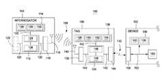
- FIG. 1is a block diagram illustrating an example system 100 for remotely configuring and/or provisioning a device, such as device 102 , when it is nonoperational.
- the system 100includes an RFID interrogator 104 and an RFID tag 106 .
- the device 102may be any electronic device that includes one or more device settings that can be programmatically or otherwise established or adjusted (collectively “set”) to configure and/or provision the device 102 for its operation.
- the device 102may be partially or completely positioned within, attached to or otherwise disposed in or on the support structure (not shown).
- the RFID interrogator 104 , the RFID tag 106 and the device 102may be adapted to establish, maintain and/or sustain (collectively “establish”) communications to one another via one or more communication links.
- the RFID interrogator 104 and the RFID tag 106may be adapted to establish a first communication via a first communication link 108
- the RFID tag 106 and the device 102may be adapted to establish a second communication via a second communication link 110 .
- the RFID interrogator 104 , the RFID tag 106 and the device 102may exchange information, such as the device state, the device settings, credentials, etc., as noted above and/or described in more detail below.
- the RFID interrogator 104may include a number of elements, many of which are not shown for simplicity of exposition.
- the RFID interrogator 104may be formed as or in a single unitary device and concentrated on a single server, client, peer or other type node. Alternatively, the RFID interrogator 104 may be formed in or from one or more separate devices, and as such, may be distributed among a number of server, client, peer or other type nodes.
- the RFID interrogator 104may be scalable (i.e., may employ scale-up and/or scale-out approaches). In addition, the RFID interrogator 104 may be a handheld device or integrated into another apparatus.
- the RFID interrogator 104includes logic 112 , memory 114 , a radio-frequency (“RF”) transceiver 116 and an antenna 118 ; some or all of which may be coupled together via one or more communication links 120 .
- the RFID interrogator 104may also include, as an option, an input/output (“I/O interface”) 122 for communicating with a source of data external to the RFID interrogator 104 (“external-data source”); not shown.
- I/O interfaceinput/output
- the logic 112is operable to control, manipulate or otherwise interact with the memory 114 , RF transceiver 116 , and/or the I/O interface 122 via the respective communication links 120 .
- the logic 112may include one or more processing units (collectively “processor”) 124 and support circuits 126 .
- the processor 124may be one or more conventional processors, microprocessors, multi-core processors and/or microcontrollers.
- the support circuits 126facilitate operation of the processor 124 and may include well-known circuitry or circuits, including, for example, an I/O interface; cache; clock circuits; power supplies; and the like.
- the memory 114may store and/or receive requests from the processor 124 to obtain the device settings 126 that can set to configure and/or provision the device 102 for its operation.
- the memory 112may store and/or receive requests from the processor 124 to obtain various software packages, such as an operating system 128 and software for causing the RFID tag 106 to program the device (“tag-instruction software 130 ”).
- the memory 114may also store and receive requests from the processor 122 to obtain operands, operators, dimensional values, configurations, and other data that are used by the operating system 128 and the tag-instruction software 130 to control operation of and/or to facilitate performing the functions of the RFID interrogator 104 .
- the memory 114may be or employ random access memory, read-only memory, optical storage, magnetic storage, removable storage, erasable programmable read only memory and variations thereof, content addressable memory and variations thereof, flash memory, disk drive storage, removable storage, any combination thereof, and the like.
- the communication links 118provide for transmissions of analog or digital information among the logic 112 , the memory 114 , the RF transceiver 116 and other portions of the RFID interrogator 104 (shown and not shown).
- the I/O interface 122is adapted to control transmissions of information, such as the device settings 126 , between (shown and not shown) elements of the RFID interrogator 104 , such as the logic 112 and the memory 114 .
- the I/O interface 122is adapted to control transmissions of information, such as the device settings 126 , between elements of the RFID interrogator 104 , the external-data source and other I/O devices disposed within, associated with or otherwise attached or coupled to the RFID interrogator 104 .
- the I/O devicesinclude (i) a monitor, (ii) any or any combination of storage devices, including but not limited to, a tape drive, a floppy drive, a hard disk drive or a compact disk drive, (iii) a receiver and/or a transmitter, (iv) a speaker, (v) a display, (vi) a speech synthesizer, (vii) an output port, and (viii) the like.
- the operating system 128may include code for operating the RFID interrogator 104 and for providing a platform onto which the tag-instruction software 130 can be executed.
- the tag-instruction software 130may be in any of a standalone, client/server, peer-to-peer and other format, and may include code for facilitating the remote configuring and/or provisioning of the device 102 .
- the tag-instruction software 130may include, for example, code for programmatically or otherwise establishing or adjusting the RFID tag 104 so as to cause it to configure and/or provision the device 102 for its operation.
- This codemay be adapted to control, manipulate or otherwise interact with the RF transceiver 116 to cause it to establish the first communication with the RFID tag 106 , via communication link 108 .
- the RFID interrogator 104may inventory, access and/or exchange the device settings 126 with the RFID tag 106 .
- the codemay cause the RF transceiver 116 to instruct or otherwise cause the RFID tag 106 to establish, via a second communication link 110 , the second communication with the device 102 .
- the RF transceiver 116may be adapted to operate in accordance with EPCTM Radio-Frequency Identity Protocols Class-1 Generation-2 UHF RFID Protocol for Communications at 860 MHz-960 MHz Version 1.1.0, EPC Global Inc., 2006; which is incorporated herein by reference in its entirety.
- the RF transceiver 116may be adapted to operate in accordance with other communication protocols as well.
- the RF transceiver 116 and the tag-instruction software 130may be adapted to operate in accordance with one or more security protocols that are compatible with the RFID tag 106 . Using these security protocols, the RF transceiver 116 and the tag-instruction software 130 are operable to cause the RFID interrogator 104 to substantiate its identity, and in turn, receive authorization to access the RFID tag 106 .
- the RF transceiver 116may broadcast or otherwise emit out antenna 132 one or more outbound RF signals and receive back from the RFID tag 106 , via the antenna 132 , one or more inbound RF signals. These signals may have be low frequency (“LF”), high frequency (“HF”), ultra-high frequency (“UHF”), etc.
- LFlow frequency
- HFhigh frequency
- UHFultra-high frequency
- RFID interrogator 104is generally located remotely and physically separate from the RFID tag 104 , the device 102 and/or the support structure, the RFID interrogator 104 may be positioned or otherwise located in close enough proximity to the (i) RFID tag 106 , (ii) device 102 and/or (iii) support structure so as to allow the outbound-RF signals to radiate to RFID tag 106 .
- the RFID tag 104 , the device 102 and/or the support structuremay be positioned or otherwise located in close enough proximity to the RFID interrogator 104 so as to allow the outbound-RF signals to radiate to RFID tag 106 .
- the outbound RF signalsmay include two types of RF signals, namely, (i) modulated-RF signals for providing the device settings 126 and/or other information to the RFID tag 106 and (ii) unmodulated-RF signals for causing the RFID tag 106 to provide information back to the RFID interrogator 104 .
- the modulated-RF signalincludes a carrier that may be modulated with one or more outbound commands for inventorying, accessing and/or otherwise interacting with the RFID tag 104 .
- These outbound commandsmay include one or more commands for transferring the device settings 126 and/or other information from the RFID interrogator to the RFID tag 106 , and in turn, to the device 102 .
- the inbound RF signalsmay include one or more modulated-RF signals that are formed by the RFID tag 106 modulating the unmodulated-RF signals (“tag-modulated signals”) with one or more inbound commands and backscattering the tag-modulated-RF signals to the RFID interrogator 104 .
- These inbound commandswhich the tag-instruction software 130 may expect to receive, may include one or more commands for transferring from the RFID tag 106 information, such as device state 150 .
- the RFID tag 106may include a number of elements, many of which are not shown for simplicity of exposition.
- the RFID tag 106is formed from and/or is adapted operate in accordance with some or all functions carried out by any type (e.g., passive, active, or semi-passive) of RFID tag.
- the RFID tag 106is generally formed as or in a single unitary device and concentrated on a single server, client, peer or other type node.
- the RFID tag 106may be formed in or from one or more separate devices, and as such, may be distributed among a number of server, client, peer or other type nodes.
- the RFID tag 106may be integrated, disposed onto or otherwise incorporated into the device 102 and/or the support structure.
- the RFID tag 106includes logic 134 , memory 136 , an RF transceiver 138 , an antenna 140 and an I/O interface 144 ; some or all of which may be coupled together via one or more communication links 142 .
- the logic 134is operable to control, manipulate or otherwise interact with the memory 136 , the RF transceiver 138 , and/or the I/O interface 144 via the respective communication links 144 .
- the logic 134may include one or more processing units (collectively “processor”) 146 and support circuits 148 .
- the processor 146may be one or more conventional processors, microprocessors, multi-core processors and/or microcontrollers.
- the support circuits 148facilitate operation of the processor 144 and may include well-known circuitry or circuits, including, for example, an I/O interface; cache; clock circuits; power supplies; and the like.
- the memory 136may store and/or receive requests from the processor 144 to obtain the device settings 126 that are transferred from the RFID interrogator 104 , and/or the device state 150 .
- the memory 136may store and/or receive requests from the processor 144 to obtain various software packages, such as an operating system 152 and software for programming the device (“device-programming software 154 ”).
- the memory 136may also store and receive requests from the processor 146 to obtain operands, operators, dimensional values, configurations, and other data that are used by the operating system 152 and the device-programming software 154 to control operation of and/or to facilitate performing the functions of the RFID tag 106 .
- the memory 136may be or employ random access memory, read-only memory, optical storage, magnetic storage, removable storage, erasable programmable read only memory and variations thereof, content addressable memory and variations thereof, flash memory, disk drive storage, removable storage, any combination thereof, and the like.
- the communication links 142provide for transmissions of analog or digital information among the logic 134 , the memory 136 , RF transceiver 138 and other portions of the RFID tag 106 (shown and not shown).
- the I/O interface 144is adapted to control transmissions of information, such as the device settings 126 and the device state 150 , between (shown and not shown) elements of the RFID tag 106 , such as the logic 134 and the memory 136 .
- the I/O interface 144is adapted to control transmissions of information, such as the device settings 126 and the device state 150 , between the RFID tag 104 and the device 102 .
- the operating system 152may include code for operating the RFID tag 104 and for providing a platform onto which the device-programming software 154 can be executed.
- the device-programming software 154is generally in a standalone format, and includes code for facilitating the remote configuring and/or provisioning of the device 102 .
- the device-programming software 154may be in any of a server, client, peer-to-peer and other format (e.g., when the RFID tag 104 is distributed among more than one node).
- the device-programming software 154may include, for example, code for programmatically or otherwise establishing or adjusting the device 102 so as to configure and/or provision the device 102 for its operation.
- This codemay be adapted to control, manipulate or otherwise interact with the RF transceiver 138 to cause it to establish the first communication with the RFID interrogator 104 , via communication link 108 .
- the RFID tag 104 and the RFID interrogator 104may exchange, via the first communication, the device settings 126 and/or the device state 150 .
- the codemay be adapted to cause the RF transceiver 138 to cause the RFID tag 106 to establish, via a second communication link 110 , the second communication with the device 102 .
- the RF transceiver 138may be adapted to operate in accordance with the above-incorporated EPCTM Radio-Frequency Identity Protocols Class-1 Generation-2 UHF RFID Protocol for Communications at 860 MHz-960 MHz Version 1.1.0, EPC Global Inc., 2006.
- the RF transceiver 138may be adapted to operate with other communication protocols as well.
- the RF transceiver 138may be adapted to (i) receive from the RFID interrogator 104 the modulated-RF signals, and where appropriate, (ii) backscatter out antenna 132 the tag-modulated-RF signals. In addition to receiving the outbound commands, the RF transceiver 138 may use the modulated-RF signals (e.g., extract electromagnetic energy contained therein) to power the RFID tag 106 .
- the modulated-RF signalse.g., extract electromagnetic energy contained therein
- the RFID tag 106may be adapted to use the power to establish the first and second communications.
- the RFID tag 106may also be adapted to use and/or transmit the power to the device 102 so as to set the device settings 126 when the device 102 , as a whole or portions thereof, are otherwise unpowered.
- the device 102may be adapted to obtain the modulated-RF and/or unmodulated-RF signals and extract the electromagnetic energy contained therein for powering the device 102 to allow the device settings 126 to be set when the device 102 , as a whole or portions thereof, are otherwise unpowered.
- RFID tag 106is generally located remotely and physically separate from the RFID interrogator 104 , the RFID tag 106 may be positioned or otherwise located in close enough proximity to the RFID interrogator 104 so as to allow the tag-modulated-RF signals to radiate to RFID interrogator 104 .
- the RFID tag 104in general, is positioned proximate and/or affixed to the device 102 and/or the support structure.
- the RFID tag 104may be positioned or otherwise located in close enough proximity to the device 102 so as to allow for exchange, via the second communication link 110 , of the device settings 126 , and if obtained from the device, the device state 150 .
- the second communication link 110may be, for example, a wiring harness or other wired or wireless link that allows the RFID tag 106 to be physically separate from the device 102 and/or support structure, yet exchange with the device 102 the device settings 126 , and if appropriate, the device state 150 .
- the second communication link 110may be a bus, ribbon cable or other wired or wireless link that allows the RFID tag 106 to be disposed on or proximate to the device 102 and/or support structure.
- the second communication link 110may take other forms as well.
- the second communication link 110may be adapted to communicate according to one or more protocols for communicating serially, in parallel, asynchronously, synchronously, etc.
- the device-programming software 154may include code that is adapted to prevent or inhibit setting the device settings 126 unless the device 102 is nonoperational. To facilitate determining whether the device 102 is nonoperational, the device-programming software 154 may include code adapted to obtain the device state 150 from the device 102 , via the second communication.
- the device-programming software 154may include code adapted to determine the device state 150 by way of an evaluation of the device 102 .
- the codemay be adapted to deduce the device state 150 by polling, monitoring and/or examining the device 102 for indicators of the device state 150 (“device-state indicators”).
- device-state indicatorsinclude, for example, an indicator signifying that the device 102 is powered or unpowered, an indicator signifying that one or more interfaces of the device 102 (shown and not shown) are operational or nonoperational, etc.
- This codemay set the device state 150 to signify that the device 102 is nonoperational responsive to deducing that the device state indicators signify that the device 102 is nonoperational.
- the device-programming software 154may also include code that is adapted to employ the security policies to limit setting the device settings 126 .
- This codemay, for example, request that the RFID interrogator 106 provide, in accordance with the security policies, one or more credentials for authentication (“authentication credentials”).
- the codemay be adapted to employ, in accordance with the security policies, the different security levels based on the nonoperational state.
- the security levelsmay be hierarchal in terms of requiring, from one of security levels (i.e., a lower security level) to another of the security level (i.e., a higher security level), additional constraints for establishing the first communication with and/or gaining access to the RFID tag 106 .
- the security policiesmay define, for example, three security levels, namely, a first security level, a second security level and a third security level.
- the first security levelmay have less constraints (i.e., be less secure) than the second security level, which may have less constraints (i.e., be less secure) than the third security level.
- the first security levelmay not require that the RFID interrogator 104 provide the authentication credentials.
- the second security levelmay require that RFID interrogator 104 provide a user name and/or password as the authentication credentials.
- the third security levelmay require that the authentication credentials provided by the RFID interrogator 104 be substantiated by a third party (e.g., a certification authority).
- the codemay be adapted to employ the security levels as a function of the nonoperational state.
- the RFID tag 104may be adapted to employ (i) the first security level when the nonoperational state signifies that the device 102 is unpowered; and (ii) the second or third security levels when the nonoperational state signifies that the device 102 is powered, but otherwise non-operational.
- the codemay also be adapted to employ other security levels when the nonoperational state signifies that the device 102 is operational. While three security levels are discussed herein, the security policies may define any number of security levels.
- the device 102may include a number of elements, many of which are not shown for simplicity of exposition. As shown, the device 102 includes a memory 156 , I/O interface 158 , and logic 160 , which are communicatively coupled via a bus or other type of communication link 162 .
- the memory 156may store the device settings 126 that are transferred from the RFID interrogator 104 and the device state 150 as provided by the device 102 .
- the memory 156may be or employ random access memory (“RAM”) and variations thereof, such as non-volatile RAM, optical storage, magnetic storage, removable storage, erasable programmable read only memory and variations thereof, content addressable memory and variations thereof, flash memory, disk drive storage, any combination thereof, and the like.
- RAMrandom access memory
- the I/O interface 158may be adapted to process and respond to requests from the RFID tag 106 and/or the RFID interrogator 104 for the device state 126 , including providing the device state 126 to the RFID tag 106 and/or the RFID interrogator 104 .
- the I/O interface 158may be adapted to provide the device settings 126 to the memory 156 .
- the I/O interface 156may be adapted to do so using direct memory access or other memory access mechanism.
- the I/O interface 156may facilitate carrying out the second communications using communication and security protocols compatible with second communication link 110 .
- the logic 160in general, controls and/or monitors the operation of the device 102 .
- This logic 160may be adapted to store the device state 150 in the memory 156 .
- the logic 160may be adapted to determine the device state 150 on-the-fly and report the device state 150 to the I/O interface 158 .
- the logic 160may do so responsive to the I/O interface 158 requesting the device state 150 .
- FIG. 2a flow diagram illustrating an example flow 200 for configuring and/or provisioning a device is shown.
- the flow 200is described with reference to the system 100 of FIG. 1 .
- the flow 200may be carried out using other architectures as well.
- the followinguses possessive form with respect to the RFID interrogator 104 , the RFID tag 106 and/or the device 102 so as to differentiate the elements of thereof.
- the flow 200begins at termination block 202 , and then transitions to process block 204 .
- the device state 150is detected via (e.g., using, by the use of, by way of, through, by, etc.) the RFID tag 106 .
- the RFID tag 106may detect the device state 150
- the RFID interrogator 106may detect the device state 150 by way of the RFID tag 106 .
- the RFID tag 106operates autonomously or substantially autonomously from the RFID interrogator 104 when detecting the device state 150 .
- RFID interrogator 104substantially controls or otherwise causes the RFID tag 106 to operate under its control when detecting the device state 150 .
- the RFID tag 106may operate autonomously when, for example, it is formed from and/or is adapted operate in accordance with some or all functions carried out by an active or semi-passive or other powered type of RFID tag, and when the tag's logic 134 and/or the device-programming software 154 are adapted to carry out the detection.
- this mode(“autonomous mode”), the RFID tag 106 may carry out the detection at any time and/or without obtaining power or receiving a request for the device state 150 (“device-state request”) from the RFID interrogator 104 . This way, the RFID tag 106 may maintain the device state 150 in the tag's memory 136 , which allows it to provide the device state 150 upon receiving the device-state request.
- the RFID tag 106may operate substantially autonomously when, for example, it is formed from and/or is adapted operate in accordance with some or all functions carried out by any type of RFID tag, and when the tag's logic 134 and/or the device-programming software 154 are adapted to carry out the detection.
- this mode(“semi-autonomous mode”), the RFID tag 106 may carry out the detection responsive to obtaining power from and/or receiving the device-state or other request from the RFID interrogator 104 . Additionally, the RFID tag 106 may carry out the detection in the semi-autonomous mode responsive to receiving from the RFID interrogator 104 an instruction, command, trigger for causing the RFID tag 106 to carry out the detection.
- the RFID interrogator 104may substantially control or cause the RFID tag 106 to operate under its control when, for example, the tag's logic 134 and/or the device-programming software 154 are not adapted to carry out the detection in accordance with the autonomous or semi-autonomous modes.
- this mode(“host-controlled mode”), the RFID interrogator 104 may use the RFID tag 106 as a conduit to the device 102 . This may be carried out, for example, by the RFID interrogator 104 and the RFID tag 106 entering a master/slave relationship or otherwise causing the RFID tag 106 to carry out instructions that the RFID interrogator 104 broadcasts, emits or otherwise transmits (collectively “transmits”).
- the RFID interrogator 104 and the RFID tag 106may establish the first communication via the first communication link 108 .
- the RFID interrogator 104is placed or otherwise located in close enough proximity to the (i) RFID tag 106 , (ii) device 102 and/or (iii) support structure (or vice versa) so as to allow (i) the outbound-RF signals transmitted from the interrogator's RF transceiver 116 to radiate to the tag's antenna 140 , and/or (ii) the inbound-RF signals backscattered from the tag's transceiver 138 to radiate to the interrogator's antenna 118 .
- the RFID interrogator 104may carry out an inventorying session with the RFID tag 106 .
- This inventorying sessionmay be carried out in accordance with Appendix E of above-incorporated EPCTM Radio-Frequency Identity Protocols Class-1 Generation-2 UHF RFID Protocol for Communications at 860 MHz-960 MHz Version 1.1.0, EPC Global Inc., 2006.
- the interrogator's RF transceiver 116transmits, via the modulated-RF signals, information for causing the RFID tag 106 to (i) energize (if not otherwise powered), and (ii) enter a state that indicates that the RFID interrogator 104 and the RFID tag 106 are securely partnered and that the RFID tag 106 grants access to the RFID interrogator 104 (“secured state”).
- the interrogator's RF transceiver 116may simply transmit, via the modulated-RF signals, information for causing the RFID tag 106 to energize.
- the tag's logic 134may interrogate the device 102 .
- the tag's logic 134 and/or the device-programming software 154operate under control of the tag-instruction software 130 .
- the tag's logic 134operates under control of the device-programming software 154 , and may interrogate the device 102 in response to receiving the device-state request or at any time after energizing.
- the tag's logic 134operates under control of the device-programming software 154 , and may interrogate the device 102 at any time.
- the tag's logic 134establishes the second communication with the device 102 , and if appropriate, transmits power to the device 102 .
- the tag's logic 134may poll the device's I/O interface 158 for the device state 150 (“device-state poll”).
- the tag's logic 134may transmit to the device's I/O interface 158 a query or other request for the device state 150 (“device-state query”).
- the device's I/O interface 158accesses the device's memory 156 and obtains the device state 150 . After obtaining the device state 150 , the device's I/O interface 158 transmits to the tag's logic 134 a response to the device-state poll/query (“device-state response”), which includes the device state 150 . The tag's logic 134 , in turn, receives the device-state response and extracts the device state 150 . After extraction, the tag's logic 134 stores the device state 150 in the tag's memory 136 .
- the device's I/O interface 158may transmit or relay the device-state poll/query to the device's logic 160 .
- the device's logic 160may perform an evaluation of the device 102 to obtain the device state 150 , and then transmit the device-state response to the device's I/O interface 160 .
- the device's I/O interface 158may transmit or relay the device-state response to the tag's logic 134 .
- the tag's logic 134receives the device-state response and extracts the device state 150 . After extraction, the tag's logic 134 stores the device state 150 in the tag's memory 136 .
- the tag's logic 134may detect the device state 150 by evaluating the device 102 .
- the tag's logic 134may, for example, poll, monitor and/or examine the device's I/O interface 158 for one or more of the device-state indicators. Responsive to polling, monitoring, and/or examining the device's I/O interface 158 , the tag's logic 134 may store the device-state indicators in the tag's memory 136 as the device state 150 .
- the tag's logic 134may cause the tag's RF transceiver 138 to transmit the device state 150 to the interrogator's antenna 118 . This may be done responsive to the interrogator's transceiver 116 transmitting the device-state request to the RFID tag 106 . In the semi-autonomous and/or autonomous modes, however, the device state 150 might not be transmitted to the RFID interrogator 104 .
- the process 200may transition to decision block 206 .
- decision block 206a determination is made as to whether the device 102 is nonoperational.
- the RFID tag 104may operate in one of the autonomous, semi-autonomous, or host-controlled modes when making the determination.
- the tag-instruction software 130makes the determination.
- the device-programming software 154makes the determination.
- the tag-instruction software 130 or the device-programming softwaremakes the determination.
- the tag-instruction software 130 or the device-programming software 154evaluates the device state 150 .
- the determinationis answered affirmatively (“affirmative determination”) and the process 200 transitions to process block 208 .
- the device state 150signifies that the device 102 is operational, then the determination is answered negatively and the process 200 transitions to termination block 210 .
- the tag's logic 134may cause the tag's RF transceiver 138 to transmit to the interrogator's antenna 118 information (“nonoperational information”) that indicates that (i) the device state 150 signifies that the device 102 is nonoperational or (ii) the device-programming software 154 has determined that the device state 150 signifies that the device 102 is nonoperational.
- the RFID interrogator 104provides the device settings to the device 102 via the RFID tag 104 .
- the RFID interrogator 104 and the RFID tag 106establish the first communication and carry out the inventorying session if they have not already done so.
- the interrogator's RF transceiver 116transmits to the tag's antenna 140 a command to set the device settings 126 (“device-setting command”).
- This device-setting commandincludes the device settings 126 , which were obtained from the interrogator's memory 114 .
- the device-programming software 154causes the tag's logic 134 to extract the device settings 126 from the device-setting command. After extraction, the device-programming software 154 causes the tag's logic 134 to transmit the device settings 126 to the device's I/O interface 158 . After receiving the device settings 126 , the device's I/O interface 158 stores the device settings 126 in the device's memory 156 .
- the RFID tag 106 and/or the device 102tear down or otherwise end the second communication, and the RFID interrogator 104 and the RFID tag tear down or otherwise end the first communication.
- the device 102may use one or more the device settings during its operation.
- the flow 200may transition to termination block 210 , at which point the flow 200 terminates.
- the flow 200may be repeated periodically, in continuous fashion, or upon being triggered as a result of a condition, such as an addition, deletion or modification of one or more of the device settings.
- the one or more of the blocks 204 - 208may be repeated periodically, in continuous fashion, or upon being triggered as a result of a condition, so as to cause additional configuring and/or provisioning of the device 102 .
- FIGS. 3A-3Ca flow diagram 300 illustrating an example communication flow 300 for configuring and/or provisioning a device is shown.
- the communication flow 300is described with reference to the system 100 of FIG. 1 .
- the communication flow 300may be carried out using other architectures as well.
- the flow 300starts at flow indicator 302 , at which point the RFID interrogator 104 has been placed or otherwise located in close enough proximity to the (I) RFID tag 106 , (ii) device 102 and/or (iii) the support structure (or vice versa) so as to allow (i) the outbound-RF signals emitted from the interrogator's RF transceiver 116 to radiate to the tag's antenna 118 , and (ii) the inbound-RF signals backscattered from the tag's transceiver 138 to radiate to the interrogator's antenna 140 .
- the interrogator's RF transceiver 116transmits, via the modulated-RF signals, information for causing the RFID tag 106 to energize and enter a state that indicates that it is ready to communicate (“ready state”).
- the interrogator's RF transceiver 116transmits to the RFID tag 106 , via the modulated-RF signals, a query command, as shown at flow indicator 304 . Responsive to the query command, the RFID tag 106 may enter into a state that indicates that it will reply to the query command (“reply state”).
- the tag's transceiver 138transmits to the RFID interrogator 104 , via the tag-modulated signals, a pseudorandom number (“PRN”) associated therewith.
- PRNpseudorandom number
- the interrogator's RF transceiver 116transmits to the RFID tag 106 , via the modulated-RF signals, an acknowledge (“ACK”) command, which acknowledges receipt of the PRN, as shown at flow indicator 308 .
- the ACK commandincludes, as a parameter, the PRN.
- the RFID tag 106may enter into a state that indicates that it acknowledged the ACK command (“acknowledged state”).
- the tag's transceiver 138transmits to the RFID interrogator 104 , via the tag-modulated-RF signals, protocol-control (“PC”) bits and an electronic-product code (“EPC”) associated therewith.
- PCprotocol-control
- EPCelectronic-product code
- the PC bits and the EPCmay be defined in accordance with the above-incorporated EPCTM Radio-Frequency Identity Protocols Class-1 Generation-2 UHF RFID Protocol for Communications at 860 MHz-960 MHz Version 1.1.0, EPC Global Inc., 2006.
- the PC bits and EPCmay be defined in other ways as well.
- the interrogator's RF transceiver 116transmits to the RFID tag 106 , via the modulated-RF signals, a request-for-PRN (“REQ_RN”) command.
- the REQ_RN commandmay include, as a parameter, the PRN.
- the RFID tag 106may enter into a state that indicates that the RFID interrogator 104 and the RFID tag 106 are securely partnered and that the RFID tag 106 grants access to the RFID interrogator 104 (“secured state”).
- the tag's transceiver 138transmits to the RFID interrogator 104 , via the tag-modulated-RF signals, a handle associated therewith.
- the handlemay be defined in accordance with the above-incorporated EPCTM Radio-Frequency Identity Protocols Class-1 Generation-2 UHF RFID Protocol for Communications at 860 MHz-960 MHz Version 1.1.0, EPC Global Inc., 2006.
- the handlemay be defined in other ways as well.
- the interrogator's RF transceiver 116may transmit to the RFID tag 106 , via the modulated-RF signals, a command to cause the RFID tag 106 to establish the second communication and obtain the device state 150 (“device-state command”). Responsive to the device-state command, the RFID tag 106 enters a state that indicates that it on hold (“arbitrate state”), as shown at flow indicator 318 .
- the communication flow 300may transition to either flow indicator 322 or flow indicator 336 after entering the arbitrate state.
- the tag's logic 134under control of the device-programming software 154 or the tag-instruction software 130 , as appropriate, transmits the device-state request to the device's I/O interface 158 via the tag's I/O interface 144 .
- the communication flow 300may transition to process block 324 .
- the communication flow 300may transition to process block 330 or flow indicator 336 when the tag's logic 134 does not receive the device-state response from the device 102 .
- the device's I/O interface 158obtains the device state 150 from the device's memory 156 .
- the device's I/O interface 158transmits the device-state response, as indicated at the flow indicator 326 .
- the device-programming software 154extracts the device state 150 from the device-state response, as shown in process block 328 .
- the communication flow 300may transition to process block 332 .
- the communication flow 300may, optionally, transition to process block 330 .
- the device-programming software 154may determine that the device state 150 signifies that the device 102 is nonoperational. The device-programming software 154 may do so by (i) evaluating whether device state 150 extracted from the device-state response signifies that the device 102 is nonoperational, or (ii) deducing that by not receiving the device-state response the device is unpowered or otherwise nonoperational and setting the device state 150 to signify that the device 102 is nonoperational.
- the device-programming software 154might not determine that the device state 150 extracted from the device-state response signifies that the device 102 is nonoperational. Instead, such determination may be made by the tag-instruction software 130 after transferring the device state 150 to the RFID interrogator 104 .
- the communication flow 300may transition to process block 332 .
- the tag's logic 134stores the device state 150 in the tag's memory 136 . Once stored, the RFID tag 106 is operable to transfer the device state 150 to the RFID interrogator 104 .
- the communication flow 300may transition to flow indicator 334 . If, the communication flow 300 transitioned to the flow indicator 336 instead of the flow indicator 322 , then tag's logic 134 may poll, monitor and/or examine the device's I/O interface 158 for one or more of the device-state indicators. Responsively, the tag's logic 134 obtains the device-state indicators from the device's I/O interface 158 and processes them into the device state. After this, the communication flow 300 may transition to (i) the process blocks 330 or 332 , and/or (ii) the flow indicator 334 .
- the communication flow 300may transition to flow indicator 340 ( FIG. 3C ).
- the interrogator's RF transceiver 116may transmit to the RFID tag 106 , via the modulated-RF signals, a second device-state command. Responsive to the second device-state command, the RFID tag 106 may enter into the reply state, as shown at flow indicator 322 .
- the tag's logic 134After entering the reply state, the tag's logic 134 obtains the device state 150 from the tag's memory 136 .
- the tag's transceiver 138transmits the device state 150 to the RFID interrogator 104 , via the tag-modulated-RF signals.
- the tag's transceiver 138may transmit to the RFID interrogator 104 , via the tag-modulated-RF signals, the nonoperational information. This way, the tag-instruction software 130 need not determine whether the device state 150 signifies that the device 102 is nonoperational.
- the interrogator's RF transceiver 116After receiving the device state 150 and/or the nonoperational information or determining that the device state 150 signifies that the device 102 nonoperational, the interrogator's RF transceiver 116 , via the modulated-RF signals, transmits to the tag's antenna 140 the device-setting command. Responsive to the device-setting command, the RFID tag 106 enters the arbitrate state, as shown at flow indicator 346 .
- the device-programming software 154After entering the arbitrate state, the device-programming software 154 causes the tag's logic 134 to transmit a request to set the device settings 126 (“device-setting request”) or relay the device-setting command to the device's I/O interface 158 . After receiving the device-setting request/command, the device's I/O interface 158 extracts the device settings 126 and stores them in the device's memory 156 .
- the device's I/O interface 158transmits an acknowledgement to the device-setting request/command (“device-set ACK”). After receiving the device-set ACK, the RFID tag 106 remains in the arbitrate state, but is prepared to enter the reply state. In addition, the device-programming software 154 may cause the tag's logic 134 to end the second communication.
- the interrogator's RF transceiver 116may transmit to the RFID tag 106 , via the modulated-RF signals, a second device-setting command, as shown at flow indicator 350 . Responsive to the second device-second command, the RFID tag 106 may enter into the reply state, as shown at flow indicator 352 . After entering the reply state, the tag's transceiver 138 transmits or relays the device-set ACK to the RFID interrogator 104 , via the tag-modulated-RF signals.
- the RFID interrogator 104 and the RFID tagtear down the first communication. After tearing down the second communication, the communication flow 300 may terminate. Alternatively, the communication flow 300 may be repeated periodically, in continuous fashion, or upon being triggered as a result of a condition, such as an addition, deletion or modification of one or more of the device settings.
- FIG. 4is a flow diagram illustrating an example flow 400 for configuring and/or provisioning a device.
- the flow 400is described with reference to the system 100 of FIG. 1 and the flow 200 of FIG. 2 .
- the flow 200may be carried out using other architectures as well.
- the followinguses possessive form with respect to the RFID interrogator 104 , the RFID tag 106 and/or the device 102 so as to differentiate the elements of thereof.
- the flow 400is similar to the flow 200 of FIG. 2 , except as described herein below.
- the flow 400transitions to process block 402 .
- the RFID tag 106employs one or more of the security policies.
- the RFID tag 106or more specifically, the tag's logic 134 causes the tag's RF transceiver 138 to transmit, via the tag-modulated-RF signal, a request for security credentials (“authentication request”) to the interrogator's antenna 118 . This may be done responsive to the interrogator's transceiver 116 transmitting the device-state request and/or the device-setting request to the RFID tag 106 .
- the interrogator's RF transceiver 138may transmit, via the modulated-RF signals, a response to the authentication request (“authentication response”).
- This authentication responseincludes the appropriate authentication credentials.
- the appropriate authentication credentials requested and received by the RFID tag 106may differ based on the nonoperational state, as noted above. If, for example, the nonoperational state indicates that the device 102 is unpowered, then the RFID tag 106 may employ the first security level, and accordingly, might not request any authentication credentials. Alternatively, the RFID tag 106 employ the second and/or third security levels when the nonoperational state indicates that the device 102 is powered, but otherwise nonoperational (e.g., one of the device's interfaces is active and/or the device 102 is carrying out one of the device functions via such interface).
- the flow 400may transition to process block 208 ; at which point the flow 400 may be carried out as described above with respect to flow 200 ( FIG. 2 ).
- process block 402is shown as occurring after decision block 206 , the process block 402 may be carried out during negotiation between the RFID tag 106 and the RFID interrogator establishing the first communication.
- the RFID tag 106may employ one or more of the security levels, as appropriate. If, for example, the nonoperational state is not known, then the RFID tag 106 may employ the third security level, as a conservative measure. Alternatively, the RFID tag 106 may employ the security level that requests only a shared key.
- FIG. 5is a block diagram illustrating an example system 500 for remotely configuring and/or provisioning a device, such as device 102 , when it is nonoperational.
- the system 500is similar to the system 100 , except as described herein below.
- the systemincludes a source of electromagnetic energy (“em source”) 502 and an RFID tag 504 .
- the em source 502includes a RF generator 506 and an antenna 508 .
- the RF generator 506is operable to transmit, via the antenna 508 , an RF signal (“em-RF signal”).
- the RFID tag 504includes an RF receiver 510 for receiving the em-RF signal and for using the em-RF signal to power the RFID tag 504 .
- the RFID tag 504may be adapted to use the power to establish the second communication.
- the RFID tag 106may also be adapted to use and/or transmit the power to the device 102 so as to set the device settings 126 when the device 102 , as a whole or portions thereof, are otherwise unpowered.
- the device setting 126are stored in the tag's memory 136 .
- the RFID tag 504operates in the autonomous mode or the semi-autonomous mode using the em-RF signal for powering the RFID tag 504 and/or as a trigger for carrying the flows 200 , 300 and/or 400 .
- the system 500may be used in conjunction with an RFID interrogator, such as the RF interrogator 104 of FIG. 1 .
- This RF interrogatormay be operable to transfer the device setting 126 to the RFID tag 504 .
- the tag's memory 136may be populated with the device settings 126 prior to disposing or otherwise locating the RFID tag 504 on or proximate to the device 102 or the support structure.
- FIG. 6is a block diagram illustrating an example system 600 for remotely configuring and/or provisioning a device when it is nonoperational.
- the system 500is similar to the system 100 , except as described herein below.
- the systemincludes the RFID interrogator 104 and the device 602 .
- the device 602is essentially a combination of the device 102 and the RFID interrogator ( FIG. 1 ) except that (i) the tag's I/O interface 144 is integrated into the device's I/O interface 158 , and (ii) the tag's memory 136 is integrated into the device's memory 156 .
- the device 602may operate in any of the autonomous, semi-autonomous, and/or host controlled modes.
- the system and methodmay employ alternative technologies to the RFID technologies described above, including BluetoothTM, near-field communications (e.g., near-field magnetics), sensor networks and others not mentioned herein. Although the cost of such technologies makes these embodiments less desirable at present, within the foreseeable future such embodiments may prove to be cost-effective.
- the communication links described abovemay be part of or access a communication network. This communication network may be a partial or full deployment of most any communication or computer network, and thus, can include a few or many network elements, most of which are not shown. Each of the communication networks may include circuit-switched as well as packet-data elements to provide transport, and can be public or private, terrestrial wireless or satellite, and/or wireline.
- Each of the networksmay include portions of a Public Switch Telephone Network (PSTN), the Internet, core and proprietary public networks, wireless voice and packet-data networks, such as 1 G, 2 G, 2.5 G and 3 G telecommunication networks, wireless office telephone systems (“WOTS”) and/or wireless local area networks (WLANs), including, Bluetooth and/or IEEE 802.11 WLANs, and the like.
- PSTNPublic Switch Telephone Network
- WOTSwireless office telephone systems
- WLANswireless local area networks
- Bluetooth and/or IEEE 802.11 WLANsand the like.
- such communication networkmay be configured in accordance with any communication protocols such as Advanced Mobile Phone Service (“AMPS”), Time Division Multiple Access (“TDMA”), Global System for Mobile Communications (“GSM”), and Code Division Multiple Access (“CDMA”), Universal Mobile Telecommunications Service (“UMTS”), Wide-band CDMA (“WCDMA”), ultra wideband CMDA, CDMA2000, Generic Packet Radio Services (“GPRS”), Telecommunications Industry Association's (“TIA”) IS-94 specifications, and any combination or variation thereof.
- AMPSAdvanced Mobile Phone Service
- TDMATime Division Multiple Access
- GSMGlobal System for Mobile Communications
- CDMACode Division Multiple Access
- UMTSUniversal Mobile Telecommunications Service
- WCDMAWide-band CDMA
- CDMA2000Coderic Packet Radio Services
- GPRSGeneric Packet Radio Services
- TIATelecommunications Industry Association's
- the communication protocolsmay also include any LAN, WLAN, WMAN, and/or PAN protocols, which may include any of the commonly used protocols, such as the IEEE 802.11 et seq.; IEEE 802.16 protocol, the IEEE 802.15 protocol, the ZigBee specification, the Bluetooth Specification, the WOTS specification, the HiperLAN specification, the HomeRF specification and/or any other wireless-networking protocol that promulgates rules to use freely-available, unlicensed spectrum, which in the United States includes the Industrial, Scientific, and Medical (“ISM”) bands.
- IEEE 802.11 et seq.IEEE 802.16 protocol, the IEEE 802.15 protocol, the ZigBee specification, the Bluetooth Specification, the WOTS specification, the HiperLAN specification, the HomeRF specification and/or any other wireless-networking protocol that promulgates rules to use freely-available, unlicensed spectrum, which in the United States includes the Industrial, Scientific, and Medical (“ISM”) bands.
- ISMIndustrial, Scientific, and Medical
- the communication protocolsmay include one or more protocols for hypertext-markup language (“HTML”), extensible-markup language (“XML”), Virtual Reality Modeling Language (“VRML”), file transfer protocol (“FTP”), simple-mail-transfer protocol (“SMTP”), session-initiation protocol (“SIP”), etc.
- HTTPhypertext-markup language
- XMLextensible-markup language
- VRMLVirtual Reality Modeling Language
- FTPfile transfer protocol
- SMTPsimple-mail-transfer protocol
- SIPsession-initiation protocol
- the EPCmay be used to communicate the device state 150 .
- the RFID tag 104may incorporate the device state into the EPC and provide the EPC in response to the device-state request.
- processing platforms, computing systems, controllers, and other devices containing processorsare noted. These devices may contain at least one Central Processing Unit (“CPU”) and memory.
- CPUCentral Processing Unit
- FIG. 1A block diagram illustrating an exemplary computing system
- FIG. 1A block diagram illustrating an exemplary computing system
- FIG. 1A block diagram illustrating an exemplary computing system
- FIG. 1A block diagram illustrating an exemplary computing system
- FIG. 1A block diagram illustrating an exemplary computing system
- CPUCentral Processing Unit
- an electrical systemrepresents data bits that can cause a resulting transformation or reduction of the electrical signals and the maintenance of data bits at memory locations in a memory system to thereby reconfigure or otherwise alter the CPU's operation, as well as other processing of signals.
- the memory locations where data bits are maintainedare physical locations that have particular electrical, magnetic, optical, or organic properties corresponding to or representative of the data bits. It should be understood that the exemplary embodiments are not limited to the above-mentioned platforms or CPUs and that other platforms and CPUs may support the described methods.
- the data bitsmay also be maintained on a computer readable medium including magnetic disks, optical disks, and any other volatile (e.g., Random Access Memory (“RAM”)) or non-volatile (e.g., Read-Only Memory (“ROM”)) mass storage system readable by the CPU.
- RAMRandom Access Memory
- ROMRead-Only Memory
- the computer readable mediummay include cooperating or interconnected computer readable medium, which exist exclusively on the processing system or are distributed among multiple interconnected processing systems that may be local or remote to the processing system. It should be understood that the exemplary embodiments are not limited to the above-mentioned memories and that other platforms and memories may support the described methods.
Landscapes
- Engineering & Computer Science (AREA)
- Physics & Mathematics (AREA)
- Computer Networks & Wireless Communication (AREA)
- Signal Processing (AREA)
- Automation & Control Theory (AREA)
- Computer Security & Cryptography (AREA)
- Electromagnetism (AREA)
- General Physics & Mathematics (AREA)
- Near-Field Transmission Systems (AREA)
Abstract
Description
Claims (53)
Priority Applications (1)
| Application Number | Priority Date | Filing Date | Title |
|---|---|---|---|
| US12/113,348US8098160B2 (en) | 2007-01-22 | 2008-05-01 | Method and system for remotely provisioning and/or configuring a device |
Applications Claiming Priority (2)
| Application Number | Priority Date | Filing Date | Title |
|---|---|---|---|
| US11/656,660US8063782B2 (en) | 2007-01-22 | 2007-01-22 | Remote inventory of devices |
| US12/113,348US8098160B2 (en) | 2007-01-22 | 2008-05-01 | Method and system for remotely provisioning and/or configuring a device |
Related Parent Applications (1)
| Application Number | Title | Priority Date | Filing Date |
|---|---|---|---|
| US11/656,660Continuation-In-PartUS8063782B2 (en) | 2007-01-22 | 2007-01-22 | Remote inventory of devices |
Publications (2)
| Publication Number | Publication Date |
|---|---|
| US20080204199A1 US20080204199A1 (en) | 2008-08-28 |
| US8098160B2true US8098160B2 (en) | 2012-01-17 |
Family
ID=39715230
Family Applications (1)
| Application Number | Title | Priority Date | Filing Date |
|---|---|---|---|
| US12/113,348Active2027-03-09US8098160B2 (en) | 2007-01-22 | 2008-05-01 | Method and system for remotely provisioning and/or configuring a device |
Country Status (1)
| Country | Link |
|---|---|
| US (1) | US8098160B2 (en) |
Cited By (86)
| Publication number | Priority date | Publication date | Assignee | Title |
|---|---|---|---|---|
| US20050182306A1 (en)* | 2004-02-17 | 2005-08-18 | Therasense, Inc. | Method and system for providing data communication in continuous glucose monitoring and management system |
| US20080255434A1 (en)* | 2007-04-14 | 2008-10-16 | Abbott Diabetes Care, Inc. | Method and apparatus for providing data processing and control in medical communication system |
| US20080256048A1 (en)* | 2007-04-14 | 2008-10-16 | Abbott Diabetes Care, Inc. | Method and apparatus for providing data processing and control in medical communication system |
| US20080278332A1 (en)* | 2007-05-08 | 2008-11-13 | Abbott Diabetes Care, Inc. | Analyte monitoring system and methods |
| US20080281179A1 (en)* | 2007-05-08 | 2008-11-13 | Abbott Diabetes Care, Inc. | Analyte monitoring system and methods |
| US20080287762A1 (en)* | 2007-05-14 | 2008-11-20 | Abbott Diabetes Care, Inc. | Method and apparatus for providing data processing and control in a medical communication system |
| US20080286316A1 (en)* | 2007-05-18 | 2008-11-20 | Heidi Kay | Lipid raft, caveolin protein, and caveolar function modulation compounds and associated synthetic and therapeutic methods |
| US20080288204A1 (en)* | 2007-04-14 | 2008-11-20 | Abbott Diabetes Care, Inc. | Method and apparatus for providing data processing and control in medical communication system |
| US20080287761A1 (en)* | 2007-05-14 | 2008-11-20 | Abbott Diabetes Care, Inc. | Method and apparatus for providing data processing and control in a medical communication system |
| US20080312845A1 (en)* | 2007-05-14 | 2008-12-18 | Abbott Diabetes Care, Inc. | Method and apparatus for providing data processing and control in a medical communication system |
| US20080319294A1 (en)* | 2007-06-21 | 2008-12-25 | Abbott Diabetes Care, Inc. | Health management devices and methods |
| US20080319295A1 (en)* | 2007-06-21 | 2008-12-25 | Abbott Diabetes Care, Inc. | Health management devices and methods |
| US20080319296A1 (en)* | 2007-06-21 | 2008-12-25 | Abbott Diabetes Care, Inc. | Health monitor |
| US20090036760A1 (en)* | 2007-07-31 | 2009-02-05 | Abbott Diabetes Care, Inc. | Method and apparatus for providing data processing and control in a medical communication system |
| US20090105571A1 (en)* | 2006-06-30 | 2009-04-23 | Abbott Diabetes Care, Inc. | Method and System for Providing Data Communication in Data Management Systems |
| US20100082266A1 (en)* | 2003-04-04 | 2010-04-01 | Abbott Diabetes Care Inc. | Method and System for Transferring Analyte Test Data |
| US20100171610A1 (en)* | 2003-04-28 | 2010-07-08 | Abbott Diabetes Care Inc. | Method and Apparatus for Providing Peak Detection Circuitry for Data Communication Systems |
| US20100198034A1 (en)* | 2009-02-03 | 2010-08-05 | Abbott Diabetes Care Inc. | Compact On-Body Physiological Monitoring Devices and Methods Thereof |
| US20100235439A1 (en)* | 2003-07-15 | 2010-09-16 | Abbott Diabetes Care Inc. | Glucose Measuring Device Integrated Into A Holster For A Personal Area Network Device |
| US20100274108A1 (en)* | 2005-09-30 | 2010-10-28 | Abbott Diabetes Care Inc. | Method and Apparatus for Providing Rechargeable Power in Data Monitoring and Management Systems |
| US20110044333A1 (en)* | 2008-05-30 | 2011-02-24 | Abbott Diabetes Care Inc. | Close Proximity Communication Device and Methods |
| US20110054282A1 (en)* | 2009-08-31 | 2011-03-03 | Abbott Diabetes Care Inc. | Analyte Monitoring System and Methods for Managing Power and Noise |
| US20110099590A1 (en)* | 2009-10-26 | 2011-04-28 | Lg Electronics Inc. | Digital broadcasting system and method of processing data in digital broadcasting system |
| US20110184268A1 (en)* | 2010-01-22 | 2011-07-28 | Abbott Diabetes Care Inc. | Method, Device and System for Providing Analyte Sensor Calibration |
| US20110213225A1 (en)* | 2009-08-31 | 2011-09-01 | Abbott Diabetes Care Inc. | Medical devices and methods |
| US20110224525A1 (en)* | 2005-10-31 | 2011-09-15 | Abbott Diabetes Care Inc. | Method and Apparatus for Providing Data Communication in Data Monitoring and Management Systems |
| US8444560B2 (en) | 2007-05-14 | 2013-05-21 | Abbott Diabetes Care Inc. | Method and apparatus for providing data processing and control in a medical communication system |
| US8456301B2 (en) | 2007-05-08 | 2013-06-04 | Abbott Diabetes Care Inc. | Analyte monitoring system and methods |
| US8461985B2 (en) | 2007-05-08 | 2013-06-11 | Abbott Diabetes Care Inc. | Analyte monitoring system and methods |
| US8471714B2 (en) | 2005-05-17 | 2013-06-25 | Abbott Diabetes Care Inc. | Method and system for providing data management in data monitoring system |
| US8543183B2 (en) | 2006-03-31 | 2013-09-24 | Abbott Diabetes Care Inc. | Analyte monitoring and management system and methods therefor |
| US8542122B2 (en) | 2005-02-08 | 2013-09-24 | Abbott Diabetes Care Inc. | Glucose measurement device and methods using RFID |
| US20130271268A1 (en)* | 2012-04-12 | 2013-10-17 | Nxp B.V. | Control method, controlled device, user interaction device and computer program product |
| US8571808B2 (en) | 2007-05-14 | 2013-10-29 | Abbott Diabetes Care Inc. | Method and apparatus for providing data processing and control in a medical communication system |
| US20130288601A1 (en)* | 2012-04-26 | 2013-10-31 | Apple Inc. | Automatic configuration of electronic devices |
| US8593287B2 (en) | 2007-05-08 | 2013-11-26 | Abbott Diabetes Care Inc. | Analyte monitoring system and methods |
| US8593109B2 (en) | 2006-03-31 | 2013-11-26 | Abbott Diabetes Care Inc. | Method and system for powering an electronic device |
| US8612163B2 (en) | 2007-05-14 | 2013-12-17 | Abbott Diabetes Care Inc. | Method and apparatus for providing data processing and control in a medical communication system |
| US8635046B2 (en) | 2010-06-23 | 2014-01-21 | Abbott Diabetes Care Inc. | Method and system for evaluating analyte sensor response characteristics |
| US8682615B2 (en) | 2007-05-14 | 2014-03-25 | Abbott Diabetes Care Inc. | Method and apparatus for providing data processing and control in a medical communication system |
| US8710993B2 (en) | 2011-11-23 | 2014-04-29 | Abbott Diabetes Care Inc. | Mitigating single point failure of devices in an analyte monitoring system and methods thereof |
| US8834366B2 (en) | 2007-07-31 | 2014-09-16 | Abbott Diabetes Care Inc. | Method and apparatus for providing analyte sensor calibration |
| US9069536B2 (en) | 2011-10-31 | 2015-06-30 | Abbott Diabetes Care Inc. | Electronic devices having integrated reset systems and methods thereof |
| US9088452B2 (en) | 2009-04-29 | 2015-07-21 | Abbott Diabetes Care Inc. | Method and system for providing data communication in continuous glucose monitoring and management system |
| US9095290B2 (en) | 2007-03-01 | 2015-08-04 | Abbott Diabetes Care Inc. | Method and apparatus for providing rolling data in communication systems |
| US9125548B2 (en) | 2007-05-14 | 2015-09-08 | Abbott Diabetes Care Inc. | Method and apparatus for providing data processing and control in a medical communication system |
| US9226701B2 (en) | 2009-04-28 | 2016-01-05 | Abbott Diabetes Care Inc. | Error detection in critical repeating data in a wireless sensor system |
| US9317656B2 (en) | 2011-11-23 | 2016-04-19 | Abbott Diabetes Care Inc. | Compatibility mechanisms for devices in a continuous analyte monitoring system and methods thereof |
| US9474475B1 (en) | 2013-03-15 | 2016-10-25 | Abbott Diabetes Care Inc. | Multi-rate analyte sensor data collection with sample rate configurable signal processing |
| US9532737B2 (en) | 2011-02-28 | 2017-01-03 | Abbott Diabetes Care Inc. | Devices, systems, and methods associated with analyte monitoring devices and devices incorporating the same |
| US9574914B2 (en) | 2007-05-08 | 2017-02-21 | Abbott Diabetes Care Inc. | Method and device for determining elapsed sensor life |
| US9622691B2 (en) | 2011-10-31 | 2017-04-18 | Abbott Diabetes Care Inc. | Model based variable risk false glucose threshold alarm prevention mechanism |
| US9662056B2 (en) | 2008-09-30 | 2017-05-30 | Abbott Diabetes Care Inc. | Optimizing analyte sensor calibration |
| US9750444B2 (en) | 2009-09-30 | 2017-09-05 | Abbott Diabetes Care Inc. | Interconnect for on-body analyte monitoring device |
| US9907492B2 (en) | 2012-09-26 | 2018-03-06 | Abbott Diabetes Care Inc. | Method and apparatus for improving lag correction during in vivo measurement of analyte concentration with analyte concentration variability and range data |
| US9913600B2 (en) | 2007-06-29 | 2018-03-13 | Abbott Diabetes Care Inc. | Analyte monitoring and management device and method to analyze the frequency of user interaction with the device |
| US9962091B2 (en) | 2002-12-31 | 2018-05-08 | Abbott Diabetes Care Inc. | Continuous glucose monitoring system and methods of use |
| US9968306B2 (en) | 2012-09-17 | 2018-05-15 | Abbott Diabetes Care Inc. | Methods and apparatuses for providing adverse condition notification with enhanced wireless communication range in analyte monitoring systems |
| US9980669B2 (en) | 2011-11-07 | 2018-05-29 | Abbott Diabetes Care Inc. | Analyte monitoring device and methods |
| US10002233B2 (en) | 2007-05-14 | 2018-06-19 | Abbott Diabetes Care Inc. | Method and apparatus for providing data processing and control in a medical communication system |
| US10022499B2 (en) | 2007-02-15 | 2018-07-17 | Abbott Diabetes Care Inc. | Device and method for automatic data acquisition and/or detection |
| US10076285B2 (en) | 2013-03-15 | 2018-09-18 | Abbott Diabetes Care Inc. | Sensor fault detection using analyte sensor data pattern comparison |
| US10111608B2 (en) | 2007-04-14 | 2018-10-30 | Abbott Diabetes Care Inc. | Method and apparatus for providing data processing and control in medical communication system |
| US10132793B2 (en) | 2012-08-30 | 2018-11-20 | Abbott Diabetes Care Inc. | Dropout detection in continuous analyte monitoring data during data excursions |
| US10136845B2 (en) | 2011-02-28 | 2018-11-27 | Abbott Diabetes Care Inc. | Devices, systems, and methods associated with analyte monitoring devices and devices incorporating the same |
| US10159433B2 (en) | 2006-02-28 | 2018-12-25 | Abbott Diabetes Care Inc. | Analyte sensor transmitter unit configuration for a data monitoring and management system |
| US10433773B1 (en) | 2013-03-15 | 2019-10-08 | Abbott Diabetes Care Inc. | Noise rejection methods and apparatus for sparsely sampled analyte sensor data |
| US10445727B1 (en)* | 2007-10-18 | 2019-10-15 | Jpmorgan Chase Bank, N.A. | System and method for issuing circulation trading financial instruments with smart features |
| US20200344320A1 (en)* | 2006-11-15 | 2020-10-29 | Conviva Inc. | Facilitating client decisions |
| US10848436B1 (en) | 2014-12-08 | 2020-11-24 | Conviva Inc. | Dynamic bitrate range selection in the cloud for optimized video streaming |
| US10848540B1 (en) | 2012-09-05 | 2020-11-24 | Conviva Inc. | Virtual resource locator |
| US10862994B1 (en)* | 2006-11-15 | 2020-12-08 | Conviva Inc. | Facilitating client decisions |
| US10873615B1 (en) | 2012-09-05 | 2020-12-22 | Conviva Inc. | Source assignment based on network partitioning |
| US10887363B1 (en) | 2014-12-08 | 2021-01-05 | Conviva Inc. | Streaming decision in the cloud |
| US10911344B1 (en) | 2006-11-15 | 2021-02-02 | Conviva Inc. | Dynamic client logging and reporting |
| US10963417B2 (en) | 2004-06-04 | 2021-03-30 | Abbott Diabetes Care Inc. | Systems and methods for managing diabetes care data |
| US11213226B2 (en) | 2010-10-07 | 2022-01-04 | Abbott Diabetes Care Inc. | Analyte monitoring devices and methods |
| US11553883B2 (en) | 2015-07-10 | 2023-01-17 | Abbott Diabetes Care Inc. | System, device and method of dynamic glucose profile response to physiological parameters |
| US11596330B2 (en) | 2017-03-21 | 2023-03-07 | Abbott Diabetes Care Inc. | Methods, devices and system for providing diabetic condition diagnosis and therapy |
| US11717225B2 (en) | 2014-03-30 | 2023-08-08 | Abbott Diabetes Care Inc. | Method and apparatus for determining meal start and peak events in analyte monitoring systems |
| US11793936B2 (en) | 2009-05-29 | 2023-10-24 | Abbott Diabetes Care Inc. | Medical device antenna systems having external antenna configurations |
| US12239463B2 (en) | 2020-08-31 | 2025-03-04 | Abbott Diabetes Care Inc. | Systems, devices, and methods for analyte sensor insertion |
| US12268496B2 (en) | 2017-01-23 | 2025-04-08 | Abbott Diabetes Care Inc. | Systems, devices and methods for analyte sensor insertion |
| US12274548B2 (en) | 2006-10-23 | 2025-04-15 | Abbott Diabetes Care Inc. | Sensor insertion devices and methods of use |
| US12279866B2 (en) | 2012-10-30 | 2025-04-22 | Abbott Diabetes Care Inc. | Sensitivity calibration of in vivo sensors used to measure analyte concentration |
| US12290354B2 (en) | 2011-06-16 | 2025-05-06 | Abbott Diabetes Care Inc. | Temperature-compensated analyte monitoring devices, systems, and methods thereof |
Families Citing this family (22)
| Publication number | Priority date | Publication date | Assignee | Title |
|---|---|---|---|---|
| US7996879B1 (en)* | 2007-07-03 | 2011-08-09 | Trend Micro Incorporated | Network deployment techniques employing radio frequency identification (RFID) |
| TWI455037B (en)* | 2008-09-12 | 2014-10-01 | Mstar Semiconductor Inc | Controlling method for rfid tag and rfid system thereof |
| KR101208081B1 (en) | 2009-05-08 | 2012-12-05 | 한국전자통신연구원 | Personal privacy protection method in service based on electronic tag |
| US8587409B2 (en)* | 2010-03-08 | 2013-11-19 | Electronics And Telecommunications Research Institute | Radio security leader controlling operation mode, and radio security tag supporting security mode and normal mode |
| US9013278B2 (en)* | 2010-08-16 | 2015-04-21 | Nxp, B.V. | System and method for responding to a request received at an object with an RFID device |
| WO2012129796A1 (en)* | 2011-03-30 | 2012-10-04 | Siemens Aktiengesellschaft | A method for configuring a wireless device and a wireless device and system |
| EP2832007B1 (en)* | 2012-03-31 | 2020-07-29 | Intel Corporation | Proximate communication with a target device |
| US11817939B2 (en) | 2012-03-31 | 2023-11-14 | Intel Corporation | Proximate communication with a target device |
| US8849708B2 (en)* | 2012-12-14 | 2014-09-30 | Amazon Technologies, Inc. | Device customization during order fulfillment utilizing an embedded electronic tag |
| US9219721B2 (en)* | 2013-03-15 | 2015-12-22 | The Chamberlain Group, Inc. | Automated credentialing of device newly added to a network |
| KR102051369B1 (en)* | 2013-04-09 | 2019-12-03 | 엘지전자 주식회사 | A Home Appliance, System AND A Controlling Method for A Home Appliance |
| US9754090B2 (en)* | 2014-05-07 | 2017-09-05 | Vivint, Inc. | Setting up a system with a mobile device |
| US9473233B2 (en)* | 2014-06-18 | 2016-10-18 | Samsung Electronics Co., Ltd. | Method and apparatus for transmitting data using relay device |
| FR3023097A1 (en)* | 2014-06-27 | 2016-01-01 | Orange | METHOD FOR CONFIGURING A COMMUNICATION DEVICE |
| KR20170100473A (en)* | 2014-09-18 | 2017-09-04 | 부즈 알렌 해밀톤 인코포레이티드 | System and method for location-based security |
| US9841490B1 (en) | 2017-01-17 | 2017-12-12 | Booz Allen Hamilton Inc. | System and method for detecting movement of a mobile asset and controlling operations of the asset based on its movement |
| CA3198521C (en)* | 2017-02-24 | 2024-02-27 | Fonex Data Systems Inc. | System and method for programming pluggable transceivers |
| US20180375965A1 (en)* | 2017-06-21 | 2018-12-27 | The Chamberlain Group, Inc. | Packaged Product Configuration |
| US10061933B1 (en) | 2018-01-09 | 2018-08-28 | Booz Allen Hamilton Inc. | System and method for controlling the power states of a mobile computing device |
| JP2019148893A (en)* | 2018-02-26 | 2019-09-05 | 京セラ株式会社 | Setting system, electronic equipment, setting method, and setting program |
| US20220413875A1 (en)* | 2021-06-29 | 2022-12-29 | Nvidia Corporation | Rack component detection and communication |
| EP4418706A1 (en)* | 2023-02-15 | 2024-08-21 | Schneider Electric Industries Sas | Configuration of an industrial communication system |
Citations (22)
| Publication number | Priority date | Publication date | Assignee | Title |
|---|---|---|---|---|
| US5974500A (en) | 1997-11-14 | 1999-10-26 | Atmel Corporation | Memory device having programmable access protection and method of operating the same |
| US6046676A (en)* | 1997-11-14 | 2000-04-04 | International Business Machines Corporation | Self powered electronic memory identification tag with dual communication ports |
| US20040153539A1 (en)* | 2003-01-30 | 2004-08-05 | Lyon Geoff M. | Device data |
| WO2005081088A1 (en) | 2004-02-25 | 2005-09-01 | Accenture Global Services Gmbh | Rfid protected media system and method |
| US20050227669A1 (en)* | 2004-04-08 | 2005-10-13 | Ixi Mobile (R&D) Ltd. | Security key management system and method in a mobile communication network |
| US20060015752A1 (en) | 2004-07-16 | 2006-01-19 | Promega Corporation | Memory having RFID tag, decryption technique for use with the memory, and memory reader or writer for use with the memory |
| US20060174319A1 (en)* | 2005-01-28 | 2006-08-03 | Kraemer Jeffrey A | Methods and apparatus providing security for multiple operational states of a computerized device |
| US7106175B2 (en)* | 1998-12-16 | 2006-09-12 | Symbol Technologies, Inc. | Wireless communication devices configurable via passive tags |
| US20060258289A1 (en)* | 2005-05-12 | 2006-11-16 | Robin Dua | Wireless media system and player and method of operation |
| US7148803B2 (en) | 2003-10-24 | 2006-12-12 | Symbol Technologies, Inc. | Radio frequency identification (RFID) based sensor networks |
| US7180422B2 (en)* | 2003-12-29 | 2007-02-20 | Intel Corporation | Asset management methods and apparatus |
| US20070143162A1 (en)* | 2005-11-15 | 2007-06-21 | Ils Technology Llc | RFID with two tier connectivity, RFID in the PLC rack, secure RFID tags and RFID multiplexer system |
| US7240848B1 (en) | 2006-09-06 | 2007-07-10 | Atmel Corporation | Three port RF interface chip |
| US20070265984A1 (en)* | 2006-04-24 | 2007-11-15 | Prakash Santhana | Financial transaction using mobile devices |
| US20070282747A1 (en) | 2006-05-08 | 2007-12-06 | Eran Shen | Secure storage digital kiosk distribution |
| US20080041930A1 (en)* | 2006-08-17 | 2008-02-21 | Smith Joshua R | Device configuration with RFID |
| US20080077632A1 (en)* | 2006-09-22 | 2008-03-27 | Tysowski Piotr K | Schema updating for synchronizing databases connected by wireless interface |
| US20080155262A1 (en)* | 2006-12-21 | 2008-06-26 | Donald Rozinak Beaver | System and method for tamper evident certification |
| US20080157925A1 (en)* | 2007-01-03 | 2008-07-03 | Intelleflex Corporation | Long range rfid device used with display, and systems and methods implementing same |
| US7436307B2 (en)* | 2005-06-01 | 2008-10-14 | Schneider Electric Industries Sas | Method and system for setting parameters of a field station in a communications network |
| US7450008B2 (en)* | 2005-11-10 | 2008-11-11 | International Business Machines Corporation | Sending service data to an RFID tag while an attached computer system is powered off |
| US7580361B2 (en)* | 2002-06-21 | 2009-08-25 | Brother Kogyo Kabushiki Kaisha | Network system, information processor and electronic apparatus |
- 2008
- 2008-05-01USUS12/113,348patent/US8098160B2/enactiveActive
Patent Citations (22)
| Publication number | Priority date | Publication date | Assignee | Title |
|---|---|---|---|---|
| US6046676A (en)* | 1997-11-14 | 2000-04-04 | International Business Machines Corporation | Self powered electronic memory identification tag with dual communication ports |
| US5974500A (en) | 1997-11-14 | 1999-10-26 | Atmel Corporation | Memory device having programmable access protection and method of operating the same |
| US7106175B2 (en)* | 1998-12-16 | 2006-09-12 | Symbol Technologies, Inc. | Wireless communication devices configurable via passive tags |
| US7580361B2 (en)* | 2002-06-21 | 2009-08-25 | Brother Kogyo Kabushiki Kaisha | Network system, information processor and electronic apparatus |
| US20040153539A1 (en)* | 2003-01-30 | 2004-08-05 | Lyon Geoff M. | Device data |
| US7148803B2 (en) | 2003-10-24 | 2006-12-12 | Symbol Technologies, Inc. | Radio frequency identification (RFID) based sensor networks |
| US7180422B2 (en)* | 2003-12-29 | 2007-02-20 | Intel Corporation | Asset management methods and apparatus |
| WO2005081088A1 (en) | 2004-02-25 | 2005-09-01 | Accenture Global Services Gmbh | Rfid protected media system and method |
| US20050227669A1 (en)* | 2004-04-08 | 2005-10-13 | Ixi Mobile (R&D) Ltd. | Security key management system and method in a mobile communication network |
| US20060015752A1 (en) | 2004-07-16 | 2006-01-19 | Promega Corporation | Memory having RFID tag, decryption technique for use with the memory, and memory reader or writer for use with the memory |
| US20060174319A1 (en)* | 2005-01-28 | 2006-08-03 | Kraemer Jeffrey A | Methods and apparatus providing security for multiple operational states of a computerized device |
| US20060258289A1 (en)* | 2005-05-12 | 2006-11-16 | Robin Dua | Wireless media system and player and method of operation |
| US7436307B2 (en)* | 2005-06-01 | 2008-10-14 | Schneider Electric Industries Sas | Method and system for setting parameters of a field station in a communications network |
| US7450008B2 (en)* | 2005-11-10 | 2008-11-11 | International Business Machines Corporation | Sending service data to an RFID tag while an attached computer system is powered off |
| US20070143162A1 (en)* | 2005-11-15 | 2007-06-21 | Ils Technology Llc | RFID with two tier connectivity, RFID in the PLC rack, secure RFID tags and RFID multiplexer system |
| US20070265984A1 (en)* | 2006-04-24 | 2007-11-15 | Prakash Santhana | Financial transaction using mobile devices |
| US20070282747A1 (en) | 2006-05-08 | 2007-12-06 | Eran Shen | Secure storage digital kiosk distribution |
| US20080041930A1 (en)* | 2006-08-17 | 2008-02-21 | Smith Joshua R | Device configuration with RFID |
| US7240848B1 (en) | 2006-09-06 | 2007-07-10 | Atmel Corporation | Three port RF interface chip |
| US20080077632A1 (en)* | 2006-09-22 | 2008-03-27 | Tysowski Piotr K | Schema updating for synchronizing databases connected by wireless interface |
| US20080155262A1 (en)* | 2006-12-21 | 2008-06-26 | Donald Rozinak Beaver | System and method for tamper evident certification |
| US20080157925A1 (en)* | 2007-01-03 | 2008-07-03 | Intelleflex Corporation | Long range rfid device used with display, and systems and methods implementing same |
Non-Patent Citations (7)
| Title |
|---|
| "Asset Identification EEPROM-AT24RF08C Datasheet, Rev. 1072E-09/99," Copyright Atmel Corporation 1999. |
| "Read/Write Crypto Transponder for Short Cycle Time-TK5561A-PP Datasheet, 4682D-RFID-09/06," Copyright 2006 Atmel Corporation. |
| "RF Identification RFID-Innovative Silicon IDIC Solutions Brochure," Copyright 2007 Atmel Corporation. |
| "RFID Application Kit TMEB8704 Application Note, Rev. 4781A-RFID-10/05," Copyright Atmel Corporation 2005. |
| "RFID External EEPROM Interface IC-AT88RF001 Datasheet, Rev. 1943F-RFID-04/02," Copyright Atmel Corporation 2002. |
| "RFID Reader Module (#28140) Datasheet," Parallax, Inc., Updated Sep. 2005. |
| "Standard Read/Write ID Transponder with Anti-collision-TK5551 Datasheet, 4709F-RFID-06/06," Copyright 2006 Atmel Corporation. |
Cited By (229)
| Publication number | Priority date | Publication date | Assignee | Title |
|---|---|---|---|---|
| US9962091B2 (en) | 2002-12-31 | 2018-05-08 | Abbott Diabetes Care Inc. | Continuous glucose monitoring system and methods of use |
| US10039881B2 (en) | 2002-12-31 | 2018-08-07 | Abbott Diabetes Care Inc. | Method and system for providing data communication in continuous glucose monitoring and management system |
| US10750952B2 (en) | 2002-12-31 | 2020-08-25 | Abbott Diabetes Care Inc. | Continuous glucose monitoring system and methods of use |
| US20100082266A1 (en)* | 2003-04-04 | 2010-04-01 | Abbott Diabetes Care Inc. | Method and System for Transferring Analyte Test Data |
| US8682598B2 (en) | 2003-04-04 | 2014-03-25 | Abbott Laboratories | Method and system for transferring analyte test data |
| US8512246B2 (en) | 2003-04-28 | 2013-08-20 | Abbott Diabetes Care Inc. | Method and apparatus for providing peak detection circuitry for data communication systems |
| US20100171610A1 (en)* | 2003-04-28 | 2010-07-08 | Abbott Diabetes Care Inc. | Method and Apparatus for Providing Peak Detection Circuitry for Data Communication Systems |
| US20100235439A1 (en)* | 2003-07-15 | 2010-09-16 | Abbott Diabetes Care Inc. | Glucose Measuring Device Integrated Into A Holster For A Personal Area Network Device |
| US20050182306A1 (en)* | 2004-02-17 | 2005-08-18 | Therasense, Inc. | Method and system for providing data communication in continuous glucose monitoring and management system |
| US8771183B2 (en) | 2004-02-17 | 2014-07-08 | Abbott Diabetes Care Inc. | Method and system for providing data communication in continuous glucose monitoring and management system |
| US10963417B2 (en) | 2004-06-04 | 2021-03-30 | Abbott Diabetes Care Inc. | Systems and methods for managing diabetes care data |
| US11182332B2 (en) | 2004-06-04 | 2021-11-23 | Abbott Diabetes Care Inc. | Systems and methods for managing diabetes care data |
| US11507530B2 (en) | 2004-06-04 | 2022-11-22 | Abbott Diabetes Care Inc. | Systems and methods for managing diabetes care data |
| US12056079B2 (en) | 2004-06-04 | 2024-08-06 | Abbott Diabetes Care Inc. | Systems and methods for managing diabetes care data |
| US8542122B2 (en) | 2005-02-08 | 2013-09-24 | Abbott Diabetes Care Inc. | Glucose measurement device and methods using RFID |
| US9332944B2 (en) | 2005-05-17 | 2016-05-10 | Abbott Diabetes Care Inc. | Method and system for providing data management in data monitoring system |
| US8653977B2 (en) | 2005-05-17 | 2014-02-18 | Abbott Diabetes Care Inc. | Method and system for providing data management in data monitoring system |
| US10206611B2 (en) | 2005-05-17 | 2019-02-19 | Abbott Diabetes Care Inc. | Method and system for providing data management in data monitoring system |
| US8471714B2 (en) | 2005-05-17 | 2013-06-25 | Abbott Diabetes Care Inc. | Method and system for providing data management in data monitoring system |
| US9750440B2 (en) | 2005-05-17 | 2017-09-05 | Abbott Diabetes Care Inc. | Method and system for providing data management in data monitoring system |
| US20100274108A1 (en)* | 2005-09-30 | 2010-10-28 | Abbott Diabetes Care Inc. | Method and Apparatus for Providing Rechargeable Power in Data Monitoring and Management Systems |
| US8638220B2 (en) | 2005-10-31 | 2014-01-28 | Abbott Diabetes Care Inc. | Method and apparatus for providing data communication in data monitoring and management systems |
| US20110224525A1 (en)* | 2005-10-31 | 2011-09-15 | Abbott Diabetes Care Inc. | Method and Apparatus for Providing Data Communication in Data Monitoring and Management Systems |
| US11179071B2 (en) | 2006-02-28 | 2021-11-23 | Abbott Diabetes Care Inc | Analyte sensor transmitter unit configuration for a data monitoring and management system |
| US11064916B2 (en) | 2006-02-28 | 2021-07-20 | Abbott Diabetes Care Inc. | Analyte sensor transmitter unit configuration for a data monitoring and management system |
| US10159433B2 (en) | 2006-02-28 | 2018-12-25 | Abbott Diabetes Care Inc. | Analyte sensor transmitter unit configuration for a data monitoring and management system |
| US10945647B2 (en) | 2006-02-28 | 2021-03-16 | Abbott Diabetes Care Inc. | Analyte sensor transmitter unit configuration for a data monitoring and management system |
| US11179072B2 (en) | 2006-02-28 | 2021-11-23 | Abbott Diabetes Care Inc. | Analyte sensor transmitter unit configuration for a data monitoring and management system |
| US9743863B2 (en) | 2006-03-31 | 2017-08-29 | Abbott Diabetes Care Inc. | Method and system for powering an electronic device |
| US8933664B2 (en) | 2006-03-31 | 2015-01-13 | Abbott Diabetes Care Inc. | Method and system for powering an electronic device |
| US9380971B2 (en) | 2006-03-31 | 2016-07-05 | Abbott Diabetes Care Inc. | Method and system for powering an electronic device |
| US8543183B2 (en) | 2006-03-31 | 2013-09-24 | Abbott Diabetes Care Inc. | Analyte monitoring and management system and methods therefor |
| US8593109B2 (en) | 2006-03-31 | 2013-11-26 | Abbott Diabetes Care Inc. | Method and system for powering an electronic device |
| US20090105571A1 (en)* | 2006-06-30 | 2009-04-23 | Abbott Diabetes Care, Inc. | Method and System for Providing Data Communication in Data Management Systems |
| US12274548B2 (en) | 2006-10-23 | 2025-04-15 | Abbott Diabetes Care Inc. | Sensor insertion devices and methods of use |
| US20200344320A1 (en)* | 2006-11-15 | 2020-10-29 | Conviva Inc. | Facilitating client decisions |
| US10911344B1 (en) | 2006-11-15 | 2021-02-02 | Conviva Inc. | Dynamic client logging and reporting |
| US10862994B1 (en)* | 2006-11-15 | 2020-12-08 | Conviva Inc. | Facilitating client decisions |
| US12166841B2 (en)* | 2006-11-15 | 2024-12-10 | Conviva Inc. | Facilitating client decisions |
| US10022499B2 (en) | 2007-02-15 | 2018-07-17 | Abbott Diabetes Care Inc. | Device and method for automatic data acquisition and/or detection |
| US10617823B2 (en) | 2007-02-15 | 2020-04-14 | Abbott Diabetes Care Inc. | Device and method for automatic data acquisition and/or detection |
| US9095290B2 (en) | 2007-03-01 | 2015-08-04 | Abbott Diabetes Care Inc. | Method and apparatus for providing rolling data in communication systems |
| US9801545B2 (en) | 2007-03-01 | 2017-10-31 | Abbott Diabetes Care Inc. | Method and apparatus for providing rolling data in communication systems |
| US12310721B2 (en) | 2007-04-14 | 2025-05-27 | Abbott Diabetes Care Inc. | Method and apparatus for providing data processing and control in medical communication system |
| US10111608B2 (en) | 2007-04-14 | 2018-10-30 | Abbott Diabetes Care Inc. | Method and apparatus for providing data processing and control in medical communication system |
| US9204827B2 (en) | 2007-04-14 | 2015-12-08 | Abbott Diabetes Care Inc. | Method and apparatus for providing data processing and control in medical communication system |
| US10349877B2 (en) | 2007-04-14 | 2019-07-16 | Abbott Diabetes Care Inc. | Method and apparatus for providing data processing and control in medical communication system |
| US20080255434A1 (en)* | 2007-04-14 | 2008-10-16 | Abbott Diabetes Care, Inc. | Method and apparatus for providing data processing and control in medical communication system |
| US9615780B2 (en) | 2007-04-14 | 2017-04-11 | Abbott Diabetes Care Inc. | Method and apparatus for providing data processing and control in medical communication system |
| US20080256048A1 (en)* | 2007-04-14 | 2008-10-16 | Abbott Diabetes Care, Inc. | Method and apparatus for providing data processing and control in medical communication system |
| US9008743B2 (en) | 2007-04-14 | 2015-04-14 | Abbott Diabetes Care Inc. | Method and apparatus for providing data processing and control in medical communication system |
| US11039767B2 (en) | 2007-04-14 | 2021-06-22 | Abbott Diabetes Care Inc. | Method and apparatus for providing data processing and control in medical communication system |
| US20080288204A1 (en)* | 2007-04-14 | 2008-11-20 | Abbott Diabetes Care, Inc. | Method and apparatus for providing data processing and control in medical communication system |
| US20080278332A1 (en)* | 2007-05-08 | 2008-11-13 | Abbott Diabetes Care, Inc. | Analyte monitoring system and methods |
| US9000929B2 (en) | 2007-05-08 | 2015-04-07 | Abbott Diabetes Care Inc. | Analyte monitoring system and methods |
| US8456301B2 (en) | 2007-05-08 | 2013-06-04 | Abbott Diabetes Care Inc. | Analyte monitoring system and methods |
| US8461985B2 (en) | 2007-05-08 | 2013-06-11 | Abbott Diabetes Care Inc. | Analyte monitoring system and methods |
| US9949678B2 (en) | 2007-05-08 | 2018-04-24 | Abbott Diabetes Care Inc. | Method and device for determining elapsed sensor life |
| US10952611B2 (en) | 2007-05-08 | 2021-03-23 | Abbott Diabetes Care Inc. | Analyte monitoring system and methods |
| US10653317B2 (en) | 2007-05-08 | 2020-05-19 | Abbott Diabetes Care Inc. | Analyte monitoring system and methods |
| US12357180B2 (en) | 2007-05-08 | 2025-07-15 | Abbott Diabetes Care Inc. | Analyte monitoring system and methods |
| US11696684B2 (en) | 2007-05-08 | 2023-07-11 | Abbott Diabetes Care Inc. | Analyte monitoring system and methods |
| US20080281179A1 (en)* | 2007-05-08 | 2008-11-13 | Abbott Diabetes Care, Inc. | Analyte monitoring system and methods |
| US9177456B2 (en) | 2007-05-08 | 2015-11-03 | Abbott Diabetes Care Inc. | Analyte monitoring system and methods |
| US9035767B2 (en) | 2007-05-08 | 2015-05-19 | Abbott Diabetes Care Inc. | Analyte monitoring system and methods |
| US9649057B2 (en) | 2007-05-08 | 2017-05-16 | Abbott Diabetes Care Inc. | Analyte monitoring system and methods |
| US10178954B2 (en) | 2007-05-08 | 2019-01-15 | Abbott Diabetes Care Inc. | Analyte monitoring system and methods |
| US9574914B2 (en) | 2007-05-08 | 2017-02-21 | Abbott Diabetes Care Inc. | Method and device for determining elapsed sensor life |
| US9314198B2 (en) | 2007-05-08 | 2016-04-19 | Abbott Diabetes Care Inc. | Analyte monitoring system and methods |
| US12396645B2 (en) | 2007-05-08 | 2025-08-26 | Abbott Diabetes Care Inc. | Analyte monitoring system and methods |
| US8593287B2 (en) | 2007-05-08 | 2013-11-26 | Abbott Diabetes Care Inc. | Analyte monitoring system and methods |
| US9060719B2 (en) | 2007-05-14 | 2015-06-23 | Abbott Diabetes Care Inc. | Method and apparatus for providing data processing and control in a medical communication system |
| US12326441B2 (en) | 2007-05-14 | 2025-06-10 | Abbott Diabetes Care Inc. | Method and apparatus for providing data processing and control in a medical communication system |
| US9125548B2 (en) | 2007-05-14 | 2015-09-08 | Abbott Diabetes Care Inc. | Method and apparatus for providing data processing and control in a medical communication system |
| US8560038B2 (en) | 2007-05-14 | 2013-10-15 | Abbott Diabetes Care Inc. | Method and apparatus for providing data processing and control in a medical communication system |
| US12402813B2 (en) | 2007-05-14 | 2025-09-02 | Abbott Diabetes Care Inc. | Method and apparatus for providing data processing and control in a medical communication system |
| US11300561B2 (en) | 2007-05-14 | 2022-04-12 | Abbott Diabetes Care, Inc. | Method and apparatus for providing data processing and control in a medical communication system |
| US10463310B2 (en) | 2007-05-14 | 2019-11-05 | Abbott Diabetes Care Inc. | Method and apparatus for providing data processing and control in a medical communication system |
| US10261069B2 (en) | 2007-05-14 | 2019-04-16 | Abbott Diabetes Care Inc. | Method and apparatus for providing data processing and control in a medical communication system |
| US8600681B2 (en) | 2007-05-14 | 2013-12-03 | Abbott Diabetes Care Inc. | Method and apparatus for providing data processing and control in a medical communication system |
| US8612163B2 (en) | 2007-05-14 | 2013-12-17 | Abbott Diabetes Care Inc. | Method and apparatus for providing data processing and control in a medical communication system |
| US10143409B2 (en) | 2007-05-14 | 2018-12-04 | Abbott Diabetes Care Inc. | Method and apparatus for providing data processing and control in a medical communication system |
| US11125592B2 (en) | 2007-05-14 | 2021-09-21 | Abbott Diabetes Care Inc. | Method and apparatus for providing data processing and control in a medical communication system |
| US9483608B2 (en) | 2007-05-14 | 2016-11-01 | Abbott Diabetes Care Inc. | Method and apparatus for providing data processing and control in a medical communication system |
| US11119090B2 (en) | 2007-05-14 | 2021-09-14 | Abbott Diabetes Care Inc. | Method and apparatus for providing data processing and control in a medical communication system |
| US10634662B2 (en) | 2007-05-14 | 2020-04-28 | Abbott Diabetes Care Inc. | Method and apparatus for providing data processing and control in a medical communication system |
| US12390135B2 (en) | 2007-05-14 | 2025-08-19 | Abbott Diabetes Care Inc. | Method and apparatus for providing data processing and control in a medical communication system |
| US8571808B2 (en) | 2007-05-14 | 2013-10-29 | Abbott Diabetes Care Inc. | Method and apparatus for providing data processing and control in a medical communication system |
| US11076785B2 (en) | 2007-05-14 | 2021-08-03 | Abbott Diabetes Care Inc. | Method and apparatus for providing data processing and control in a medical communication system |
| US10653344B2 (en) | 2007-05-14 | 2020-05-19 | Abbott Diabetes Care Inc. | Method and apparatus for providing data processing and control in a medical communication system |
| US12313622B2 (en) | 2007-05-14 | 2025-05-27 | Abbott Diabetes Care Inc. | Method and apparatus for providing data processing and control in a medical communication system |
| US8444560B2 (en) | 2007-05-14 | 2013-05-21 | Abbott Diabetes Care Inc. | Method and apparatus for providing data processing and control in a medical communication system |
| US9737249B2 (en) | 2007-05-14 | 2017-08-22 | Abbott Diabetes Care Inc. | Method and apparatus for providing data processing and control in a medical communication system |
| US10976304B2 (en) | 2007-05-14 | 2021-04-13 | Abbott Diabetes Care Inc. | Method and apparatus for providing data processing and control in a medical communication system |
| US10119956B2 (en) | 2007-05-14 | 2018-11-06 | Abbott Diabetes Care Inc. | Method and apparatus for providing data processing and control in a medical communication system |
| US8682615B2 (en) | 2007-05-14 | 2014-03-25 | Abbott Diabetes Care Inc. | Method and apparatus for providing data processing and control in a medical communication system |
| US20080287762A1 (en)* | 2007-05-14 | 2008-11-20 | Abbott Diabetes Care, Inc. | Method and apparatus for providing data processing and control in a medical communication system |
| US9797880B2 (en) | 2007-05-14 | 2017-10-24 | Abbott Diabetes Care Inc. | Method and apparatus for providing data processing and control in a medical communication system |
| US9804150B2 (en) | 2007-05-14 | 2017-10-31 | Abbott Diabetes Care Inc. | Method and apparatus for providing data processing and control in a medical communication system |
| US9801571B2 (en) | 2007-05-14 | 2017-10-31 | Abbott Diabetes Care Inc. | Method and apparatus for providing data processing and control in medical communication system |
| US10045720B2 (en) | 2007-05-14 | 2018-08-14 | Abbott Diabetes Care Inc. | Method and apparatus for providing data processing and control in a medical communication system |
| US10031002B2 (en) | 2007-05-14 | 2018-07-24 | Abbott Diabetes Care Inc. | Method and apparatus for providing data processing and control in a medical communication system |
| US11828748B2 (en) | 2007-05-14 | 2023-11-28 | Abbott Diabetes Care Inc. | Method and apparatus for providing data processing and control in a medical communication system |
| US10002233B2 (en) | 2007-05-14 | 2018-06-19 | Abbott Diabetes Care Inc. | Method and apparatus for providing data processing and control in a medical communication system |
| US10820841B2 (en) | 2007-05-14 | 2020-11-03 | Abbot Diabetes Care Inc. | Method and apparatus for providing data processing and control in a medical communication system |
| US20080287761A1 (en)* | 2007-05-14 | 2008-11-20 | Abbott Diabetes Care, Inc. | Method and apparatus for providing data processing and control in a medical communication system |
| US20080312845A1 (en)* | 2007-05-14 | 2008-12-18 | Abbott Diabetes Care, Inc. | Method and apparatus for providing data processing and control in a medical communication system |
| US20080286316A1 (en)* | 2007-05-18 | 2008-11-20 | Heidi Kay | Lipid raft, caveolin protein, and caveolar function modulation compounds and associated synthetic and therapeutic methods |
| US20100076280A1 (en)* | 2007-06-21 | 2010-03-25 | Abbott Diabetes Care Inc. | Health Monitor |
| US20100076289A1 (en)* | 2007-06-21 | 2010-03-25 | Abbott Diabetes Care Inc. | Health Monitor |
| US20080319294A1 (en)* | 2007-06-21 | 2008-12-25 | Abbott Diabetes Care, Inc. | Health management devices and methods |
| US20080319295A1 (en)* | 2007-06-21 | 2008-12-25 | Abbott Diabetes Care, Inc. | Health management devices and methods |
| US11276492B2 (en) | 2007-06-21 | 2022-03-15 | Abbott Diabetes Care Inc. | Health management devices and methods |
| US11264133B2 (en) | 2007-06-21 | 2022-03-01 | Abbott Diabetes Care Inc. | Health management devices and methods |
| US20080319296A1 (en)* | 2007-06-21 | 2008-12-25 | Abbott Diabetes Care, Inc. | Health monitor |
| US20100076292A1 (en)* | 2007-06-21 | 2010-03-25 | Abbott Diabetes Care Inc. | Health Monitor |
| US20100076284A1 (en)* | 2007-06-21 | 2010-03-25 | Abbott Diabetes Care Inc. | Health Management Devices and Methods |
| US20100076290A1 (en)* | 2007-06-21 | 2010-03-25 | Abbott Diabetes Care Inc. | Health Monitor |
| US8597188B2 (en) | 2007-06-21 | 2013-12-03 | Abbott Diabetes Care Inc. | Health management devices and methods |
| US8617069B2 (en) | 2007-06-21 | 2013-12-31 | Abbott Diabetes Care Inc. | Health monitor |
| US20100076291A1 (en)* | 2007-06-21 | 2010-03-25 | Abbott Diabetes Care Inc. | Health Monitor |
| US10856785B2 (en) | 2007-06-29 | 2020-12-08 | Abbott Diabetes Care Inc. | Analyte monitoring and management device and method to analyze the frequency of user interaction with the device |
| US9913600B2 (en) | 2007-06-29 | 2018-03-13 | Abbott Diabetes Care Inc. | Analyte monitoring and management device and method to analyze the frequency of user interaction with the device |
| US11678821B2 (en) | 2007-06-29 | 2023-06-20 | Abbott Diabetes Care Inc. | Analyte monitoring and management device and method to analyze the frequency of user interaction with the device |
| US12426812B2 (en) | 2007-06-29 | 2025-09-30 | Abbott Diabetes Care Inc. | Analyte monitoring and management device and method to analyze the frequency of user interaction with the device |
| US8834366B2 (en) | 2007-07-31 | 2014-09-16 | Abbott Diabetes Care Inc. | Method and apparatus for providing analyte sensor calibration |
| US9398872B2 (en) | 2007-07-31 | 2016-07-26 | Abbott Diabetes Care Inc. | Method and apparatus for providing analyte sensor calibration |
| US20090036760A1 (en)* | 2007-07-31 | 2009-02-05 | Abbott Diabetes Care, Inc. | Method and apparatus for providing data processing and control in a medical communication system |
| US11100487B2 (en)* | 2007-10-18 | 2021-08-24 | Jpmorgan Chase Bank, N.A. | System and method for issuing, circulating and trading financial instruments with smart features |
| US10445727B1 (en)* | 2007-10-18 | 2019-10-15 | Jpmorgan Chase Bank, N.A. | System and method for issuing circulation trading financial instruments with smart features |
| US8737259B2 (en) | 2008-05-30 | 2014-05-27 | Abbott Diabetes Care Inc. | Close proximity communication device and methods |
| US20110044333A1 (en)* | 2008-05-30 | 2011-02-24 | Abbott Diabetes Care Inc. | Close Proximity Communication Device and Methods |
| US8509107B2 (en) | 2008-05-30 | 2013-08-13 | Abbott Diabetes Care Inc. | Close proximity communication device and methods |
| US9184875B2 (en) | 2008-05-30 | 2015-11-10 | Abbott Diabetes Care, Inc. | Close proximity communication device and methods |
| US9831985B2 (en) | 2008-05-30 | 2017-11-28 | Abbott Diabetes Care Inc. | Close proximity communication device and methods |
| US12368529B2 (en) | 2008-05-30 | 2025-07-22 | Abbott Diabetes Care Inc. | Close proximity communication device and methods |
| US11770210B2 (en) | 2008-05-30 | 2023-09-26 | Abbott Diabetes Care Inc. | Close proximity communication device and methods |
| US11202592B2 (en) | 2008-09-30 | 2021-12-21 | Abbott Diabetes Care Inc. | Optimizing analyte sensor calibration |
| US11013439B2 (en) | 2008-09-30 | 2021-05-25 | Abbott Diabetes Care Inc. | Optimizing analyte sensor calibration |
| US9662056B2 (en) | 2008-09-30 | 2017-05-30 | Abbott Diabetes Care Inc. | Optimizing analyte sensor calibration |
| US11484234B2 (en) | 2008-09-30 | 2022-11-01 | Abbott Diabetes Care Inc. | Optimizing analyte sensor calibration |
| US12279868B2 (en) | 2008-09-30 | 2025-04-22 | Abbott Diabetes Care Inc. | Optimizing analyte sensor calibration |
| US11464434B2 (en) | 2008-09-30 | 2022-10-11 | Abbott Diabetes Care Inc. | Optimizing analyte sensor calibration |
| US12274549B2 (en) | 2008-09-30 | 2025-04-15 | Abbott Diabetes Care Inc. | Optimizing analyte sensor calibration |
| US11213229B2 (en) | 2009-02-03 | 2022-01-04 | Abbott Diabetes Care Inc. | Analyte sensor and apparatus for insertion of the sensor |
| US11202591B2 (en) | 2009-02-03 | 2021-12-21 | Abbott Diabetes Care Inc. | Analyte sensor and apparatus for insertion of the sensor |
| US11166656B2 (en) | 2009-02-03 | 2021-11-09 | Abbott Diabetes Care Inc. | Analyte sensor and apparatus for insertion of the sensor |
| US20100198034A1 (en)* | 2009-02-03 | 2010-08-05 | Abbott Diabetes Care Inc. | Compact On-Body Physiological Monitoring Devices and Methods Thereof |
| US11006870B2 (en) | 2009-02-03 | 2021-05-18 | Abbott Diabetes Care Inc. | Analyte sensor and apparatus for insertion of the sensor |
| US11006871B2 (en) | 2009-02-03 | 2021-05-18 | Abbott Diabetes Care Inc. | Analyte sensor and apparatus for insertion of the sensor |
| US11006872B2 (en) | 2009-02-03 | 2021-05-18 | Abbott Diabetes Care Inc. | Analyte sensor and apparatus for insertion of the sensor |
| US9226701B2 (en) | 2009-04-28 | 2016-01-05 | Abbott Diabetes Care Inc. | Error detection in critical repeating data in a wireless sensor system |
| US9693688B2 (en) | 2009-04-29 | 2017-07-04 | Abbott Diabetes Care Inc. | Method and system for providing data communication in continuous glucose monitoring and management system |
| US9949639B2 (en) | 2009-04-29 | 2018-04-24 | Abbott Diabetes Care Inc. | Method and system for providing data communication in continuous glucose monitoring and management system |
| US9088452B2 (en) | 2009-04-29 | 2015-07-21 | Abbott Diabetes Care Inc. | Method and system for providing data communication in continuous glucose monitoring and management system |
| US10617296B2 (en) | 2009-04-29 | 2020-04-14 | Abbott Diabetes Care Inc. | Method and system for providing data communication in continuous glucose monitoring and management system |
| US10172518B2 (en) | 2009-04-29 | 2019-01-08 | Abbott Diabetes Care Inc. | Method and system for providing data communication in continuous glucose monitoring and management system |
| US12364815B2 (en) | 2009-05-29 | 2025-07-22 | Abbott Diabetes Care Inc. | Medical device antenna systems having external antenna configurations |
| US11872370B2 (en) | 2009-05-29 | 2024-01-16 | Abbott Diabetes Care Inc. | Medical device antenna systems having external antenna configurations |
| US11793936B2 (en) | 2009-05-29 | 2023-10-24 | Abbott Diabetes Care Inc. | Medical device antenna systems having external antenna configurations |
| US11150145B2 (en) | 2009-08-31 | 2021-10-19 | Abbott Diabetes Care Inc. | Analyte monitoring system and methods for managing power and noise |
| US8993331B2 (en) | 2009-08-31 | 2015-03-31 | Abbott Diabetes Care Inc. | Analyte monitoring system and methods for managing power and noise |
| USD1010133S1 (en) | 2009-08-31 | 2024-01-02 | Abbott Diabetes Care Inc. | Analyte sensor assembly |
| US20110054282A1 (en)* | 2009-08-31 | 2011-03-03 | Abbott Diabetes Care Inc. | Analyte Monitoring System and Methods for Managing Power and Noise |
| US11635332B2 (en) | 2009-08-31 | 2023-04-25 | Abbott Diabetes Care Inc. | Analyte monitoring system and methods for managing power and noise |
| US10136816B2 (en) | 2009-08-31 | 2018-11-27 | Abbott Diabetes Care Inc. | Medical devices and methods |
| US20110213225A1 (en)* | 2009-08-31 | 2011-09-01 | Abbott Diabetes Care Inc. | Medical devices and methods |
| US12315630B2 (en) | 2009-08-31 | 2025-05-27 | Abbott Diabetes Care Inc. | Medical devices and methods |
| US10492685B2 (en) | 2009-08-31 | 2019-12-03 | Abbott Diabetes Care Inc. | Medical devices and methods |
| US10429250B2 (en) | 2009-08-31 | 2019-10-01 | Abbott Diabetes Care, Inc. | Analyte monitoring system and methods for managing power and noise |
| US11259725B2 (en) | 2009-09-30 | 2022-03-01 | Abbott Diabetes Care Inc. | Interconnect for on-body analyte monitoring device |
| US10765351B2 (en) | 2009-09-30 | 2020-09-08 | Abbott Diabetes Care Inc. | Interconnect for on-body analyte monitoring device |
| US9750444B2 (en) | 2009-09-30 | 2017-09-05 | Abbott Diabetes Care Inc. | Interconnect for on-body analyte monitoring device |
| US20110099590A1 (en)* | 2009-10-26 | 2011-04-28 | Lg Electronics Inc. | Digital broadcasting system and method of processing data in digital broadcasting system |
| US8250612B2 (en)* | 2009-10-26 | 2012-08-21 | Lg Electronics Inc. | Digital broadcasting system and method of processing data in digital broadcasting system |
| US20110184268A1 (en)* | 2010-01-22 | 2011-07-28 | Abbott Diabetes Care Inc. | Method, Device and System for Providing Analyte Sensor Calibration |
| US8635046B2 (en) | 2010-06-23 | 2014-01-21 | Abbott Diabetes Care Inc. | Method and system for evaluating analyte sensor response characteristics |
| US11213226B2 (en) | 2010-10-07 | 2022-01-04 | Abbott Diabetes Care Inc. | Analyte monitoring devices and methods |
| US10136845B2 (en) | 2011-02-28 | 2018-11-27 | Abbott Diabetes Care Inc. | Devices, systems, and methods associated with analyte monitoring devices and devices incorporating the same |
| US9532737B2 (en) | 2011-02-28 | 2017-01-03 | Abbott Diabetes Care Inc. | Devices, systems, and methods associated with analyte monitoring devices and devices incorporating the same |
| US11534089B2 (en) | 2011-02-28 | 2022-12-27 | Abbott Diabetes Care Inc. | Devices, systems, and methods associated with analyte monitoring devices and devices incorporating the same |
| US11627898B2 (en) | 2011-02-28 | 2023-04-18 | Abbott Diabetes Care Inc. | Devices, systems, and methods associated with analyte monitoring devices and devices incorporating the same |
| US12290354B2 (en) | 2011-06-16 | 2025-05-06 | Abbott Diabetes Care Inc. | Temperature-compensated analyte monitoring devices, systems, and methods thereof |
| US11406331B2 (en) | 2011-10-31 | 2022-08-09 | Abbott Diabetes Care Inc. | Model based variable risk false glucose threshold alarm prevention mechanism |
| US9913619B2 (en) | 2011-10-31 | 2018-03-13 | Abbott Diabetes Care Inc. | Model based variable risk false glucose threshold alarm prevention mechanism |
| US9069536B2 (en) | 2011-10-31 | 2015-06-30 | Abbott Diabetes Care Inc. | Electronic devices having integrated reset systems and methods thereof |
| US9622691B2 (en) | 2011-10-31 | 2017-04-18 | Abbott Diabetes Care Inc. | Model based variable risk false glucose threshold alarm prevention mechanism |
| US9465420B2 (en) | 2011-10-31 | 2016-10-11 | Abbott Diabetes Care Inc. | Electronic devices having integrated reset systems and methods thereof |
| US9980669B2 (en) | 2011-11-07 | 2018-05-29 | Abbott Diabetes Care Inc. | Analyte monitoring device and methods |
| US9743872B2 (en) | 2011-11-23 | 2017-08-29 | Abbott Diabetes Care Inc. | Mitigating single point failure of devices in an analyte monitoring system and methods thereof |
| US10939859B2 (en) | 2011-11-23 | 2021-03-09 | Abbott Diabetes Care Inc. | Mitigating single point failure of devices in an analyte monitoring system and methods thereof |
| US12364419B2 (en) | 2011-11-23 | 2025-07-22 | Abbott Diabetes Care Inc. | Mitigating single point failure of devices in an analyte monitoring system and methods thereof |
| US8710993B2 (en) | 2011-11-23 | 2014-04-29 | Abbott Diabetes Care Inc. | Mitigating single point failure of devices in an analyte monitoring system and methods thereof |
| US9289179B2 (en) | 2011-11-23 | 2016-03-22 | Abbott Diabetes Care Inc. | Mitigating single point failure of devices in an analyte monitoring system and methods thereof |
| US9317656B2 (en) | 2011-11-23 | 2016-04-19 | Abbott Diabetes Care Inc. | Compatibility mechanisms for devices in a continuous analyte monitoring system and methods thereof |
| US10136847B2 (en) | 2011-11-23 | 2018-11-27 | Abbott Diabetes Care Inc. | Mitigating single point failure of devices in an analyte monitoring system and methods thereof |
| US20130271268A1 (en)* | 2012-04-12 | 2013-10-17 | Nxp B.V. | Control method, controlled device, user interaction device and computer program product |
| US9514339B2 (en)* | 2012-04-12 | 2016-12-06 | Nxp B.V. | Control method, controlled device, user interaction device and computer program product |
| US20130288601A1 (en)* | 2012-04-26 | 2013-10-31 | Apple Inc. | Automatic configuration of electronic devices |
| TWI489295B (en)* | 2012-04-26 | 2015-06-21 | Apple Inc | Automatic configuration of electronic devices |
| US10942164B2 (en) | 2012-08-30 | 2021-03-09 | Abbott Diabetes Care Inc. | Dropout detection in continuous analyte monitoring data during data excursions |
| US10345291B2 (en) | 2012-08-30 | 2019-07-09 | Abbott Diabetes Care Inc. | Dropout detection in continuous analyte monitoring data during data excursions |
| US10656139B2 (en) | 2012-08-30 | 2020-05-19 | Abbott Diabetes Care Inc. | Dropout detection in continuous analyte monitoring data during data excursions |
| US10132793B2 (en) | 2012-08-30 | 2018-11-20 | Abbott Diabetes Care Inc. | Dropout detection in continuous analyte monitoring data during data excursions |
| US10848540B1 (en) | 2012-09-05 | 2020-11-24 | Conviva Inc. | Virtual resource locator |
| US10873615B1 (en) | 2012-09-05 | 2020-12-22 | Conviva Inc. | Source assignment based on network partitioning |
| US12419589B2 (en) | 2012-09-17 | 2025-09-23 | Abbott Diabetes Care Inc. | Methods and apparatuses for providing adverse condition notification with enhanced wireless communication range in analyte monitoring systems |
| US11950936B2 (en) | 2012-09-17 | 2024-04-09 | Abbott Diabetes Care Inc. | Methods and apparatuses for providing adverse condition notification with enhanced wireless communication range in analyte monitoring systems |
| US11612363B2 (en) | 2012-09-17 | 2023-03-28 | Abbott Diabetes Care Inc. | Methods and apparatuses for providing adverse condition notification with enhanced wireless communication range in analyte monitoring systems |
| US9968306B2 (en) | 2012-09-17 | 2018-05-15 | Abbott Diabetes Care Inc. | Methods and apparatuses for providing adverse condition notification with enhanced wireless communication range in analyte monitoring systems |
| US11896371B2 (en) | 2012-09-26 | 2024-02-13 | Abbott Diabetes Care Inc. | Method and apparatus for improving lag correction during in vivo measurement of analyte concentration with analyte concentration variability and range data |
| US10842420B2 (en) | 2012-09-26 | 2020-11-24 | Abbott Diabetes Care Inc. | Method and apparatus for improving lag correction during in vivo measurement of analyte concentration with analyte concentration variability and range data |
| US9907492B2 (en) | 2012-09-26 | 2018-03-06 | Abbott Diabetes Care Inc. | Method and apparatus for improving lag correction during in vivo measurement of analyte concentration with analyte concentration variability and range data |
| US12343140B2 (en) | 2012-09-26 | 2025-07-01 | Abbott Diabetes Care Inc. | Method and apparatus for improving lag correction during in vivo measurement of analyte concentration with analyte concentration variability and range data |
| US12279866B2 (en) | 2012-10-30 | 2025-04-22 | Abbott Diabetes Care Inc. | Sensitivity calibration of in vivo sensors used to measure analyte concentration |
| US9474475B1 (en) | 2013-03-15 | 2016-10-25 | Abbott Diabetes Care Inc. | Multi-rate analyte sensor data collection with sample rate configurable signal processing |
| US10076285B2 (en) | 2013-03-15 | 2018-09-18 | Abbott Diabetes Care Inc. | Sensor fault detection using analyte sensor data pattern comparison |
| US10433773B1 (en) | 2013-03-15 | 2019-10-08 | Abbott Diabetes Care Inc. | Noise rejection methods and apparatus for sparsely sampled analyte sensor data |
| US12171548B2 (en) | 2013-03-15 | 2024-12-24 | Abbott Diabetes Care Inc. | Multi-rate analyte sensor data collection with sample rate configurable signal processing |
| US12383164B1 (en) | 2013-03-15 | 2025-08-12 | Abbott Diabetes Care Inc. | Noise rejection methods and apparatus for sparsely sampled analyte sensor data |
| US10874336B2 (en) | 2013-03-15 | 2020-12-29 | Abbott Diabetes Care Inc. | Multi-rate analyte sensor data collection with sample rate configurable signal processing |
| US11717225B2 (en) | 2014-03-30 | 2023-08-08 | Abbott Diabetes Care Inc. | Method and apparatus for determining meal start and peak events in analyte monitoring systems |
| US10887363B1 (en) | 2014-12-08 | 2021-01-05 | Conviva Inc. | Streaming decision in the cloud |
| US10848436B1 (en) | 2014-12-08 | 2020-11-24 | Conviva Inc. | Dynamic bitrate range selection in the cloud for optimized video streaming |
| US11553883B2 (en) | 2015-07-10 | 2023-01-17 | Abbott Diabetes Care Inc. | System, device and method of dynamic glucose profile response to physiological parameters |
| US12310757B2 (en) | 2015-07-10 | 2025-05-27 | Abbott Diabetes Care Inc. | System, device and method of dynamic glucose profile response to physiological parameters |
| US12268496B2 (en) | 2017-01-23 | 2025-04-08 | Abbott Diabetes Care Inc. | Systems, devices and methods for analyte sensor insertion |
| US11596330B2 (en) | 2017-03-21 | 2023-03-07 | Abbott Diabetes Care Inc. | Methods, devices and system for providing diabetic condition diagnosis and therapy |
| US12239463B2 (en) | 2020-08-31 | 2025-03-04 | Abbott Diabetes Care Inc. | Systems, devices, and methods for analyte sensor insertion |
Also Published As
| Publication number | Publication date |
|---|---|
| US20080204199A1 (en) | 2008-08-28 |
Similar Documents
| Publication | Publication Date | Title |
|---|---|---|
| US8098160B2 (en) | Method and system for remotely provisioning and/or configuring a device | |
| US6754562B2 (en) | Method and apparatus for wireless information transfer in vehicle service systems | |
| JP5121048B2 (en) | Radio frequency identification method and radio frequency identification device from RFID tag | |
| US7386275B2 (en) | Systems and methods for managing out-of-band device connection | |
| US20060238305A1 (en) | Configurable RFID reader | |
| AU2019207606B2 (en) | System and method for controlling the power states of a mobile computing device | |
| EP2199946A1 (en) | Device configuration system and method | |
| CN107491795A (en) | Silent RFID states and recovery | |
| US20060238302A1 (en) | System and method for configuring an RFID reader | |
| US8258918B1 (en) | RFID reader controllers limiting theft of confidential information | |
| US20100026493A1 (en) | Methods and apparatus for inventory location compliance | |
| US20070143188A1 (en) | System and method for processing items placed in a container | |
| CN104967626A (en) | Apparatus and method for providing RFID identification data | |
| US20080104010A1 (en) | Configuring initialized RFID readers using RFID tags | |
| CN101647028A (en) | Method for establishing a wireless communication connection between an automation component and a mobile operating terminal | |
| US7118037B2 (en) | Radio frequency identification (RFID) household system for tracking and managing RFID tag containing household possessions within short range RF limited boundaries of a household facility | |
| CN113068185A (en) | Communication device and system | |
| EP3726413B1 (en) | Device and method for control policy retention | |
| EP2329662A1 (en) | Method of communicating with an avionics box via text messaging | |
| CN109644336A (en) | Automatic secure data transmission with motor vehicles | |
| WO2012102600A1 (en) | Portable radio frequency identification reader for real time location systems | |
| KR20160121068A (en) | Rfid patrol system of dual band type with security algorithm | |
| EP3561666B1 (en) | Mobile device with access rights management | |
| KR100974816B1 (en) | Method and system for embedding RFID tag in electronic parts and recording medium | |
| EP1872600A4 (en) | System and mehtod for configuring an rfid reader |
Legal Events
| Date | Code | Title | Description |
|---|---|---|---|
| AS | Assignment | Owner name:CISCO TECHNOLOGY, INC., CALIFORNIA Free format text:ASSIGNMENT OF ASSIGNORS INTEREST;ASSIGNORS:HOWARTH, ARTHUR;PRASAD, CHANDRODAYA;THUBERT, PASCAL;AND OTHERS;REEL/FRAME:020900/0767;SIGNING DATES FROM 20080410 TO 20080505 Owner name:CISCO TECHNOLOGY, INC.,CALIFORNIA Free format text:ASSIGNMENT OF ASSIGNORS INTEREST;ASSIGNORS:HOWARTH, ARTHUR;PRASAD, CHANDRODAYA;THUBERT, PASCAL;AND OTHERS;SIGNING DATES FROM 20080410 TO 20080505;REEL/FRAME:020900/0767 Owner name:CISCO TECHNOLOGY, INC., CALIFORNIA Free format text:ASSIGNMENT OF ASSIGNORS INTEREST;ASSIGNORS:HOWARTH, ARTHUR;PRASAD, CHANDRODAYA;THUBERT, PASCAL;AND OTHERS;SIGNING DATES FROM 20080410 TO 20080505;REEL/FRAME:020900/0767 | |
| AS | Assignment | Owner name:CISCO TECHNOLOGY, INC., CALIFORNIA Free format text:ASSIGNMENT OF ASSIGNORS INTEREST;ASSIGNOR:YAO, LEI;REEL/FRAME:022337/0238 Effective date:20090227 Owner name:CISCO TECHNOLOGY, INC., CALIFORNIA Free format text:ASSIGNMENT OF ASSIGNORS INTEREST;ASSIGNORS:GHOSH, KALYAN;PITTA, SRINIVAS;ANDREELLO, GIUSEPPE;REEL/FRAME:022338/0279 Effective date:20090302 Owner name:CISCO TECHNOLOGY, INC.,CALIFORNIA Free format text:ASSIGNMENT OF ASSIGNORS INTEREST;ASSIGNOR:YAO, LEI;REEL/FRAME:022337/0238 Effective date:20090227 Owner name:CISCO TECHNOLOGY, INC.,CALIFORNIA Free format text:ASSIGNMENT OF ASSIGNORS INTEREST;ASSIGNORS:GHOSH, KALYAN;PITTA, SRINIVAS;ANDREELLO, GIUSEPPE;REEL/FRAME:022338/0279 Effective date:20090302 | |
| STCF | Information on status: patent grant | Free format text:PATENTED CASE | |
| CC | Certificate of correction | ||
| FPAY | Fee payment | Year of fee payment:4 | |
| MAFP | Maintenance fee payment | Free format text:PAYMENT OF MAINTENANCE FEE, 8TH YEAR, LARGE ENTITY (ORIGINAL EVENT CODE: M1552); ENTITY STATUS OF PATENT OWNER: LARGE ENTITY Year of fee payment:8 | |
| MAFP | Maintenance fee payment | Free format text:PAYMENT OF MAINTENANCE FEE, 12TH YEAR, LARGE ENTITY (ORIGINAL EVENT CODE: M1553); ENTITY STATUS OF PATENT OWNER: LARGE ENTITY Year of fee payment:12 |