US8097983B2 - Wireless energy transfer - Google Patents
Wireless energy transferDownload PDFInfo
- Publication number
- US8097983B2 US8097983B2US12/437,641US43764109AUS8097983B2US 8097983 B2US8097983 B2US 8097983B2US 43764109 AUS43764109 AUS 43764109AUS 8097983 B2US8097983 B2US 8097983B2
- Authority
- US
- United States
- Prior art keywords
- resonator
- source
- energy
- resonant
- resonators
- Prior art date
- Legal status (The legal status is an assumption and is not a legal conclusion. Google has not performed a legal analysis and makes no representation as to the accuracy of the status listed.)
- Active, expires
Links
Images


Classifications
- B—PERFORMING OPERATIONS; TRANSPORTING
- B60—VEHICLES IN GENERAL
- B60L—PROPULSION OF ELECTRICALLY-PROPELLED VEHICLES; SUPPLYING ELECTRIC POWER FOR AUXILIARY EQUIPMENT OF ELECTRICALLY-PROPELLED VEHICLES; ELECTRODYNAMIC BRAKE SYSTEMS FOR VEHICLES IN GENERAL; MAGNETIC SUSPENSION OR LEVITATION FOR VEHICLES; MONITORING OPERATING VARIABLES OF ELECTRICALLY-PROPELLED VEHICLES; ELECTRIC SAFETY DEVICES FOR ELECTRICALLY-PROPELLED VEHICLES
- B60L53/00—Methods of charging batteries, specially adapted for electric vehicles; Charging stations or on-board charging equipment therefor; Exchange of energy storage elements in electric vehicles
- B60L53/10—Methods of charging batteries, specially adapted for electric vehicles; Charging stations or on-board charging equipment therefor; Exchange of energy storage elements in electric vehicles characterised by the energy transfer between the charging station and the vehicle
- B60L53/12—Inductive energy transfer
- B60L53/126—Methods for pairing a vehicle and a charging station, e.g. establishing a one-to-one relation between a wireless power transmitter and a wireless power receiver
- H—ELECTRICITY
- H01—ELECTRIC ELEMENTS
- H01Q—ANTENNAS, i.e. RADIO AERIALS
- H01Q7/00—Loop antennas with a substantially uniform current distribution around the loop and having a directional radiation pattern in a plane perpendicular to the plane of the loop
- H—ELECTRICITY
- H01—ELECTRIC ELEMENTS
- H01Q—ANTENNAS, i.e. RADIO AERIALS
- H01Q9/00—Electrically-short antennas having dimensions not more than twice the operating wavelength and consisting of conductive active radiating elements
- H01Q9/04—Resonant antennas
- H—ELECTRICITY
- H02—GENERATION; CONVERSION OR DISTRIBUTION OF ELECTRIC POWER
- H02J—CIRCUIT ARRANGEMENTS OR SYSTEMS FOR SUPPLYING OR DISTRIBUTING ELECTRIC POWER; SYSTEMS FOR STORING ELECTRIC ENERGY
- H02J50/00—Circuit arrangements or systems for wireless supply or distribution of electric power
- H02J50/10—Circuit arrangements or systems for wireless supply or distribution of electric power using inductive coupling
- H02J50/12—Circuit arrangements or systems for wireless supply or distribution of electric power using inductive coupling of the resonant type
- H—ELECTRICITY
- H02—GENERATION; CONVERSION OR DISTRIBUTION OF ELECTRIC POWER
- H02J—CIRCUIT ARRANGEMENTS OR SYSTEMS FOR SUPPLYING OR DISTRIBUTING ELECTRIC POWER; SYSTEMS FOR STORING ELECTRIC ENERGY
- H02J50/00—Circuit arrangements or systems for wireless supply or distribution of electric power
- H02J50/80—Circuit arrangements or systems for wireless supply or distribution of electric power involving the exchange of data, concerning supply or distribution of electric power, between transmitting devices and receiving devices
- H—ELECTRICITY
- H02—GENERATION; CONVERSION OR DISTRIBUTION OF ELECTRIC POWER
- H02J—CIRCUIT ARRANGEMENTS OR SYSTEMS FOR SUPPLYING OR DISTRIBUTING ELECTRIC POWER; SYSTEMS FOR STORING ELECTRIC ENERGY
- H02J50/00—Circuit arrangements or systems for wireless supply or distribution of electric power
- H02J50/90—Circuit arrangements or systems for wireless supply or distribution of electric power involving detection or optimisation of position, e.g. alignment
- H—ELECTRICITY
- H04—ELECTRIC COMMUNICATION TECHNIQUE
- H04B—TRANSMISSION
- H04B5/00—Near-field transmission systems, e.g. inductive or capacitive transmission systems
- H04B5/70—Near-field transmission systems, e.g. inductive or capacitive transmission systems specially adapted for specific purposes
- H04B5/79—Near-field transmission systems, e.g. inductive or capacitive transmission systems specially adapted for specific purposes for data transfer in combination with power transfer
- B—PERFORMING OPERATIONS; TRANSPORTING
- B60—VEHICLES IN GENERAL
- B60L—PROPULSION OF ELECTRICALLY-PROPELLED VEHICLES; SUPPLYING ELECTRIC POWER FOR AUXILIARY EQUIPMENT OF ELECTRICALLY-PROPELLED VEHICLES; ELECTRODYNAMIC BRAKE SYSTEMS FOR VEHICLES IN GENERAL; MAGNETIC SUSPENSION OR LEVITATION FOR VEHICLES; MONITORING OPERATING VARIABLES OF ELECTRICALLY-PROPELLED VEHICLES; ELECTRIC SAFETY DEVICES FOR ELECTRICALLY-PROPELLED VEHICLES
- B60L2210/00—Converter types
- B60L2210/20—AC to AC converters
- Y—GENERAL TAGGING OF NEW TECHNOLOGICAL DEVELOPMENTS; GENERAL TAGGING OF CROSS-SECTIONAL TECHNOLOGIES SPANNING OVER SEVERAL SECTIONS OF THE IPC; TECHNICAL SUBJECTS COVERED BY FORMER USPC CROSS-REFERENCE ART COLLECTIONS [XRACs] AND DIGESTS
- Y02—TECHNOLOGIES OR APPLICATIONS FOR MITIGATION OR ADAPTATION AGAINST CLIMATE CHANGE
- Y02T—CLIMATE CHANGE MITIGATION TECHNOLOGIES RELATED TO TRANSPORTATION
- Y02T10/00—Road transport of goods or passengers
- Y02T10/60—Other road transportation technologies with climate change mitigation effect
- Y02T10/70—Energy storage systems for electromobility, e.g. batteries
- Y—GENERAL TAGGING OF NEW TECHNOLOGICAL DEVELOPMENTS; GENERAL TAGGING OF CROSS-SECTIONAL TECHNOLOGIES SPANNING OVER SEVERAL SECTIONS OF THE IPC; TECHNICAL SUBJECTS COVERED BY FORMER USPC CROSS-REFERENCE ART COLLECTIONS [XRACs] AND DIGESTS
- Y02—TECHNOLOGIES OR APPLICATIONS FOR MITIGATION OR ADAPTATION AGAINST CLIMATE CHANGE
- Y02T—CLIMATE CHANGE MITIGATION TECHNOLOGIES RELATED TO TRANSPORTATION
- Y02T10/00—Road transport of goods or passengers
- Y02T10/60—Other road transportation technologies with climate change mitigation effect
- Y02T10/7072—Electromobility specific charging systems or methods for batteries, ultracapacitors, supercapacitors or double-layer capacitors
- Y—GENERAL TAGGING OF NEW TECHNOLOGICAL DEVELOPMENTS; GENERAL TAGGING OF CROSS-SECTIONAL TECHNOLOGIES SPANNING OVER SEVERAL SECTIONS OF THE IPC; TECHNICAL SUBJECTS COVERED BY FORMER USPC CROSS-REFERENCE ART COLLECTIONS [XRACs] AND DIGESTS
- Y02—TECHNOLOGIES OR APPLICATIONS FOR MITIGATION OR ADAPTATION AGAINST CLIMATE CHANGE
- Y02T—CLIMATE CHANGE MITIGATION TECHNOLOGIES RELATED TO TRANSPORTATION
- Y02T10/00—Road transport of goods or passengers
- Y02T10/60—Other road transportation technologies with climate change mitigation effect
- Y02T10/72—Electric energy management in electromobility
- Y—GENERAL TAGGING OF NEW TECHNOLOGICAL DEVELOPMENTS; GENERAL TAGGING OF CROSS-SECTIONAL TECHNOLOGIES SPANNING OVER SEVERAL SECTIONS OF THE IPC; TECHNICAL SUBJECTS COVERED BY FORMER USPC CROSS-REFERENCE ART COLLECTIONS [XRACs] AND DIGESTS
- Y02—TECHNOLOGIES OR APPLICATIONS FOR MITIGATION OR ADAPTATION AGAINST CLIMATE CHANGE
- Y02T—CLIMATE CHANGE MITIGATION TECHNOLOGIES RELATED TO TRANSPORTATION
- Y02T90/00—Enabling technologies or technologies with a potential or indirect contribution to GHG emissions mitigation
- Y02T90/10—Technologies relating to charging of electric vehicles
- Y02T90/12—Electric charging stations
- Y—GENERAL TAGGING OF NEW TECHNOLOGICAL DEVELOPMENTS; GENERAL TAGGING OF CROSS-SECTIONAL TECHNOLOGIES SPANNING OVER SEVERAL SECTIONS OF THE IPC; TECHNICAL SUBJECTS COVERED BY FORMER USPC CROSS-REFERENCE ART COLLECTIONS [XRACs] AND DIGESTS
- Y02—TECHNOLOGIES OR APPLICATIONS FOR MITIGATION OR ADAPTATION AGAINST CLIMATE CHANGE
- Y02T—CLIMATE CHANGE MITIGATION TECHNOLOGIES RELATED TO TRANSPORTATION
- Y02T90/00—Enabling technologies or technologies with a potential or indirect contribution to GHG emissions mitigation
- Y02T90/10—Technologies relating to charging of electric vehicles
- Y02T90/14—Plug-in electric vehicles
- Y—GENERAL TAGGING OF NEW TECHNOLOGICAL DEVELOPMENTS; GENERAL TAGGING OF CROSS-SECTIONAL TECHNOLOGIES SPANNING OVER SEVERAL SECTIONS OF THE IPC; TECHNICAL SUBJECTS COVERED BY FORMER USPC CROSS-REFERENCE ART COLLECTIONS [XRACs] AND DIGESTS
- Y10—TECHNICAL SUBJECTS COVERED BY FORMER USPC
- Y10T—TECHNICAL SUBJECTS COVERED BY FORMER US CLASSIFICATION
- Y10T29/00—Metal working
- Y10T29/49—Method of mechanical manufacture
- Y10T29/49002—Electrical device making
- Y10T29/4902—Electromagnet, transformer or inductor
Definitions
- Wireless energy transfermay for example, be useful in such applications as providing power to autonomous electrical or electronic devices.
- Radiative modes of omni-directional antennasare not suitable for such energy transfer, because a vast majority of energy is wasted into free space.
- Directed radiation modes, using lasers or highly-directional antennascan be efficiently used for energy transfer, even for long distances (transfer distance L TRANS >>L DEV , where L DEV is the characteristic size of the device and/or the source), but require existence of an uninterruptible line-of-sight and a complicated tracking system in the case of mobile objects.
- Some transfer schemesrely on induction, but are typically restricted to very close-range (L TRANS ⁇ L DEV ) or low power ( ⁇ mW) energy transfers.
- resonant objects with coupled resonant modes having localized evanescent field patternsmay be used for non-radiative wireless energy transfer.
- Resonant objectstend to couple, while interacting weakly with other off-resonant environmental objects.
- the energy-transfer ratecan be larger than the energy-loss rate. Accordingly, efficient wireless energy-exchange can be achieved between the resonant objects, while suffering only modest transfer and dissipation of energy into other off-resonant objects.
- the nearly-omnidirectional but stationary (non-lossy) nature of the near fieldmakes this mechanism suitable for mobile wireless receivers.
- Various embodimentstherefore have a variety of possible applications including for example, placing a source (e.g. one connected to the wired electricity network) on the ceiling of a factory room, while devices (robots, vehicles, computers, or similar) are roaming freely within the room.
- Other applicationsinclude power supplies for electric-engine buses and/or hybrid cars and medical implantable devices.
- resonant modesare so-called magnetic resonances, for which most of the energy surrounding the resonant objects is stored in the magnetic field; i.e. there is very little electric field outside of the resonant objects. Since most everyday materials (including animals, plants and humans) are non-magnetic, their interaction with magnetic fields is minimal. This is important both for safety and also to reduce interaction with the extraneous environmental objects.
- an apparatusfor use in wireless energy transfer, which includes a first resonator structure configured to transfer energy with a second resonator structure over a distance D greater than a characteristic size L 2 of the second resonator structure.
- Dis also greater than one or more of: a characteristic size L 1 of the first resonator structure, a characteristic thickness T 1 of the first resonator structure, and a characteristic width W 1 of the first resonator structure.
- the energy transferis mediated by evanescent-tail coupling of a resonant field of the first resonator structure and a resonant field of the second resonator structure.
- the apparatusmay include any of the following features alone or in combination.
- the first resonator structureis configured to transfer energy to the second resonator structure. In some embodiments, the first resonator structure is configured to receive energy from the second resonator structure. In some embodiments, the apparatus includes the second resonator structure.
- the first resonator structurehas a resonant angular frequency ⁇ 1 , a Q-factor Q 1 , and a resonance width ⁇ 1
- the second resonator structurehas a resonant angular frequency ⁇ 2 , a Q-factor Q 2 , and a resonance width ⁇ 2
- the energy transferhas a rate ⁇ .
- the absolute value of the difference of the angular frequencies ⁇ 1 and ⁇ 2is smaller than the broader of the resonant widths ⁇ 1 and ⁇ 2 .
- the coupling to loss ratiois the coupling to loss ratio
- D/L 2may be as large as 2, as large as 3, as large as 5, as large as 7, or as large as 10.
- Q 11000 and Q 2 >1000, and the coupling to loss ratio
- D/L 2may be as large as 2, as large as 3, as large as 5, as large as 7, as large as 10.
- D/L 2is as large as 2, as large as 3, as large as 5, as large as 7, or as large as 10.
- the quantity ⁇ / ⁇ square root over ( ⁇ 1 ⁇ 2 ) ⁇is maximized at an angular frequency ⁇ tilde over ( ⁇ ) ⁇ with a frequency width ⁇ tilde over ( ⁇ ) ⁇ around the maximum, and
- the absolute value of the difference of the angular frequencies ⁇ 1 and ⁇ tilde over ( ⁇ ) ⁇is smaller than the width ⁇ tilde over ( ⁇ ) ⁇
- the absolute value of the difference of the angular frequencies ⁇ 2 and ⁇ tilde over ( ⁇ ) ⁇is smaller than the width ⁇ tilde over ( ⁇ ) ⁇ .
- the energy transferoperates with an efficiency ⁇ work greater than about 1%, greater than about 10%, greater than about 30%, greater than about 50%, or greater than about 80%.
- the energy transferoperates with a radiation loss ⁇ rad less that about 10%. In some such embodiments the coupling to loss ratio
- the energy transferoperates with a radiation loss ⁇ rad less that about 1%. In some such embodiments, the coupling to loss ratio
- the energy transferin the presence of a human at distance of more than 3 cm from the surface of either resonant object, operates with a loss to the human ⁇ h of less than about 1%.
- the coupling to loss ratioin the presence of a human at distance of more than 3 cm from the surface of either resonant object, operates with a loss to the human ⁇ h of less than about 1%.
- the energy transferin the presence of a human at distance of more than 10 cm from the surface of either resonant object, operates with a loss to the human ⁇ h of less than about 0.2%. In some such embodiments the coupling to loss ratio
- a device coupled to the first or second resonator structure with a coupling rate ⁇ workreceives a usable power P work from the resonator structure.
- P workis greater than about 0.01 Watt, greater than about 0.1 Watt, greater than about 1 Watt, or greater than about 10 Watt.
- the deviceif the device is coupled to the first resonator, then 1 ⁇ 2 ⁇ [( ⁇ work / ⁇ 1 ) 2 ⁇ 1]/( ⁇ / ⁇ square root over ( ⁇ 1 ⁇ 2 ) ⁇ ) 2 ⁇ 2, or 1 ⁇ 4 ⁇ [( ⁇ work / ⁇ 1 ) 2 ⁇ 1]/( ⁇ / ⁇ square root over ( ⁇ 1 ⁇ 2 ) ⁇ ) 2 ⁇ 4, or 1 ⁇ 8 ⁇ [( ⁇ work / ⁇ 1 ) 2 ⁇ 1]/( ⁇ / ⁇ square root over ( ⁇ 1 ⁇ 2 ) ⁇ ) 2 ⁇ 8, and, if the device is coupled to the second resonator, then 1 ⁇ 2 ⁇ [( ⁇ work / ⁇ 2 ) 2 ⁇ 1]/( ⁇ / ⁇ square root over ( ⁇ 1 ⁇ 2 ) ⁇ ) 2 ⁇ 2, or 1 ⁇ 4 ⁇ [( ⁇ work / ⁇ 2 ) 2 ⁇ 1]/( ⁇ / ⁇ square root over ( ⁇ 1 ⁇ 2 ) ⁇ ) 2 ⁇ 4, or 1 ⁇ 8 ⁇ [( ⁇ work / ⁇
- the deviceincludes an electrical or electronic device.
- the deviceincludes a robot (e.g. a conventional robot or a nano-robot).
- the deviceincludes a mobile electronic device (e.g. a telephone, or a cell-phone, or a computer, or a laptop computer, or a personal digital assistant (PDA)).
- the deviceincludes an electronic device that receives information wirelessly (e.g. a wireless keyboard, or a wireless mouse, or a wireless computer screen, or a wireless television screen).
- the deviceincludes a medical device configured to be implanted in a patient (e.g. an artificial organ, or implant configured to deliver medicine).
- the deviceincludes a sensor.
- the deviceincludes a vehicle (e.g. a transportation vehicle, or an autonomous vehicle).
- the apparatusfurther includes the device.
- a power supply coupled to the first or second resonator structure with a coupling rate ⁇ supplydrives the resonator structure at a frequency f and supplies power P total .
- fis about the optimum efficiency frequency.
- the power supplyis coupled to the first resonator, then 1 ⁇ 2 ⁇ [( ⁇ supply / ⁇ 1 ) 2 ⁇ 1]/( ⁇ / ⁇ square root over ( ⁇ 1 ⁇ 2 ) ⁇ ) 2 ⁇ 2, or 1 ⁇ 4 ⁇ [( ⁇ supply / ⁇ 1 ) 2 ⁇ 1]/( ⁇ / ⁇ square root over ( ⁇ 1 ⁇ 2 ) ⁇ ) 2 ⁇ 4, or 1 ⁇ 8 ⁇ [( ⁇ supply / ⁇ 1 ) 2 ⁇ 1]/( ⁇ / ⁇ square root over ( ⁇ 1 ⁇ 2 ) ⁇ ) 2 ⁇ 8, and, if the power supply is coupled to the second resonator, then 1 ⁇ 2 ⁇ [( ⁇ supply / ⁇ 2 ) 2 ⁇ 1]/( ⁇ / ⁇ square root over ( ⁇ 1 ⁇ 2 ) ⁇ ) 2 ⁇ 2, or 1 ⁇ 4 ⁇ [( ⁇ supply / ⁇ 2 ) 2 ⁇ 1]/( ⁇ / ⁇ square root over ( ⁇ 1 ⁇ 2 ) ⁇ ) 2 ⁇ 4, or 1 ⁇ 8 ⁇ [( ⁇ [ ⁇ supply / ⁇
- the apparatusfurther includes the power source.
- the resonant fieldsare electromagnetic.
- fis about 50 GHz or less, about 1 GHz or less, about 100 MHz or less, about 10 MHz or less, about 1 MHz or less, about 100 KHz or less, or about 10 kHz or less.
- fis about 50 GHz or greater, about 1 GHz or greater, about 100 MHz or greater, about 10 MHz or greater, about 1 MHz or greater, about 100 kHz or greater, or about 10 kHz or greater.
- fis within one of the frequency bands specially assigned for industrial, scientific and medical (ISM) equipment.
- ISMindustrial, scientific and medical
- the resonant fieldsare primarily magnetic in the area outside of the resonant objects.
- the ratio of the average electric field energy to average magnetic filed energy at a distance D p from the closest resonant objectis less than 0.01, or less than 0.1.
- L Ris the characteristic size of the closest resonant object and D p /L R is less than 1.5, 3, 5, 7, or 10.
- the resonant fieldsare acoustic. In some embodiments, one or more of the resonant fields include a whispering gallery mode of one of the resonant structures.
- one of the first and second resonator structuresincludes a self resonant coil of conducting wire, conducting Litz wire, or conducting ribbon. In some embodiments, both of the first and second resonator structures include self resonant coils of conducting wire, conducting Litz wire, or conducting ribbon. In some embodiments, both of the first and second resonator structures include self resonant coils of conducting wire or conducting Litz wire or conducting ribbon, and Q 1 >300 and Q 2 >300.
- one or more of the self resonant conductive wire coilsinclude a wire of length l and cross section radius a wound into a helical coil of radius r, height h and number of turns N.
- N⁇ square root over (l 2 ⁇ h 2 ) ⁇ /2 ⁇ r.
- ris about 30 cm
- his about 20 cm
- ais about 3 mm
- Nis about 5.25
- a power source coupled to the first or second resonator structuredrives the resonator structure at a frequency f.
- fis about 10.6 MHz.
- the coupling to loss ratiois about 10.6 MHz
- D/L Ris as large as about 2, 3, 5, or 8.
- ris about 30 cm
- his about 20 cm
- ais about 1 cm
- Nis about 4
- a power source coupled to the first or second resonator structuredrives the resonator structure at a frequency f.
- fis about 13.4 MHz.
- the coupling to loss ratiois about 13.4 MHz
- D/L Ris as large as about 3, 5, 7, or 10.
- ris about 10 cm
- his about 3 cm
- ais about 2 mm
- Nis about 6
- a power source coupled to the first or second resonator structuredrives the resonator structure at a frequency f.
- fis about 21.4 MHz.
- D/L Ris as large as about 3, 5, 7, or 10.
- one of the first and second resonator structuresincludes a capacitively loaded loop or coil of conducting wire, conducting Litz wire, or conducting ribbon. In some embodiments, both of the first and second resonator structures include capacitively loaded loops or coils of conducting wire, conducting Litz wire, or conducting ribbon. In some embodiments, both of the first and second resonator structures include capacitively loaded loops or coils of conducting wire or conducting Litz wire or conducting ribbon, and Q 1 >300 and Q 2 >300.
- the characteristic size L R of the resonator structure receiving energy from the other resonator structureis less than about 1 cm and the width of the conducting wire or Litz wire or ribbon of said object is less than about 1 mm, and, during operation, a power source coupled to the first or second resonator structure drives the resonator structure at a frequency f.
- fis about 380 MHz.
- the coupling to loss ratiois about 380 MHz.
- D/L Ris as large as about 3, about 5, about 7, or about 10.
- the characteristic size of the resonator structure receiving energy from the other resonator structure L Ris less than about 10 cm and the width of the conducting wire or Litz wire or ribbon of said object is less than about 1 cm, and, during operation, a power source coupled to the first or second resonator structure drives the resonator structure at a frequency f. In some embodiments, f is about 43 MHz. In some such embodiments, the coupling to loss ratio
- D/L Ris as large as about 3, about 5, about 7, or about 10.
- the characteristic size L R of the resonator structure receiving energy from the other resonator structureis less than about 30 cm and the width of the conducting wire or Litz wire or ribbon of said object is less than about 5 cm, and, during operation, a power source coupled to the first or second resonator structure drives the resonator structure at a frequency f. In some such embodiments, f is about 9 MHz. In some such embodiments, the coupling to loss ratio
- D/L Ris as large as about 3, about 5, about 7, or about 10.
- the characteristic size of the resonator structure receiving energy from the other resonator structure L Ris less than about 30 cm and the width of the conducting wire or Litz wire or ribbon of said object is less than about 5 mm, and, during operation, a power source coupled to the first or second resonator structure drives the resonator structure at a frequency f. In some embodiments, f is about 17 MHz. In some such embodiments, the coupling to loss ratio
- D/L Ris as large as about 3, about 5, about 7, or about 10.
- the characteristic size L R of the resonator structure receiving energy from the other resonator structureis less than about 1 m, and the width of the conducting wire or Litz wire or ribbon of said object is less than about 1 cm, and, during operation, a power source coupled to the first or second resonator structure drives the resonator structure at a frequency f.
- fis about 5 MHz.
- the coupling to loss ratiois about 5 MHz.
- D/L Ris as large as about 3, about 5, about 7, or about 10.
- one of the resonator structuresreceives a usable power P w from the other resonator structure, an electrical current I s flows in the resonator structure which is transferring energy to the other resonant structure, and the ratio
- one of the resonator structuresreceives a usable power P w from the other resonator structure, a voltage difference V s appears across the capacitive element of the first resonator structure, and the ratio
- V s P wis less than about 2000 Volts/ ⁇ square root over (Watts) ⁇ or less than about 4000 Volts/ ⁇ square root over (Watts) ⁇ .
- one of the first and second resonator structuresincludes a inductively loaded rod of conducting wire or conducting Litz wire or conducting ribbon. In some embodiments, both of the first and second resonator structures include inductively loaded rods of conducting wire or conducting Litz wire or conducting ribbon. In some embodiments, both of the first and second resonator structures include inductively loaded rods of conducting wire or conducting Litz wire or conducting ribbon, and Q 1 >300 and Q 2 >300.
- the characteristic size of the resonator structure receiving energy from the other resonator structure L Ris less than about 10 cm and the width of the conducting wire or Litz wire or ribbon of said object is less than about 1 cm, and, during operation, a power source coupled to the first or second resonator structure drives the resonator structure at a frequency f. In some embodiments, f is about 14 MHz. In some such embodiments, the coupling to loss ratio
- D/L Ris as large as about 3, about 5, about 7, or about 10.
- the characteristic size L R of the resonator structure receiving energy from the other resonator structureis less than about 30 cm and the width of the conducting wire or Litz wire or ribbon of said object is less than about 5 cm, and, during operation, a power source coupled to the first or second resonator structure drives the resonator structure at a frequency f.
- fis about 2.5 MHz.
- the coupling to loss ratiois about 2.5 MHz.
- D/L Ris as large as about 3, about 5, about 7, or about 10.
- one of the first and second resonator structuresincludes a dielectric disk. In some embodiments, both of the first and second resonator structures include dielectric disks. In some embodiments, both of the first and second resonator structures include dielectric disks, and Q 1 >300 and Q 2 >300.
- the characteristic size of the resonator structure receiving energy from the other resonator structureis L R and the real part of the permittivity of said resonator structure ⁇ is less than about 150. In some such embodiments, the coupling to loss ratio
- D/L Ris as large as about 3, about 5, about 7, or about 10.
- the characteristic size of the resonator structure receiving energy from the other resonator structureis L R and the real part of the permittivity of said resonator structure ⁇ is less than about 65. In some such embodiments, the coupling to loss ratio
- D/L Ris as large as about 3, about 5, about 7.
- At least one of the first and second resonator structuresincludes one of: a dielectric material, a metallic material, a metallodielectric object, a plasmonic material, a plasmonodielectric object, a superconducting material.
- At least one of the resonatorshas a quality factor greater than about 5000, or greater than about 10000.
- the apparatusalso includes a third resonator structure configured to transfer energy with one or more of the first and second resonator structures,
- the energy transfer between the third resonator structure and the one or more of the first and second resonator structuresis mediated by evanescent-tail coupling of the resonant field of the one or more of the first and second resonator structures and a resonant field of the third resonator structure.
- the third resonator structureis configured to transfer energy to one or more of the first and second resonator structures.
- the third resonator structureis configured to receive energy from one or more of the first and second resonator structures.
- the third resonator structureis configured to receive energy from one of the first and second resonator structures and transfer energy to the other one of the first and second resonator structures.
- Some embodimentsinclude a mechanism for, during operation, maintaining the resonant frequency of one or more of the resonant objects.
- the feedback mechanismcomprises an oscillator with a fixed frequency and is configured to adjust the resonant frequency of the one or more resonant objects to be about equal to the fixed frequency.
- the feedback mechanismis configured to monitor an efficiency of the energy transfer, and adjust the resonant frequency of the one or more resonant objects to maximize the efficiency.
- a method of wireless energy transferincludes providing a first resonator structure and transferring energy with a second resonator structure over a distance D greater than a characteristic size L 2 of the second resonator structure.
- Dis also greater than one or more of: a characteristic size L 1 of the first resonator structure, a characteristic thickness T 1 of the first resonator structure, and a characteristic width W 1 of the first resonator structure.
- the energy transferis mediated by evanescent-tail coupling of a resonant field of the first resonator structure and a resonant field of the second resonator structure.
- the first resonator structureis configured to transfer energy to the second resonator structure. In some embodiments, the first resonator structure is configured to receive energy from the second resonator structure.
- the first resonator structurehas a resonant angular frequency ⁇ 1 , a Q-factor Q 1 , and a resonance width ⁇ 1
- the second resonator structurehas a resonant angular frequency ⁇ 2 , a Q-factor Q 2 , and a resonance width ⁇ 2
- the energy transferhas a rate ⁇ .
- the absolute value of the difference of the angular frequencies ⁇ 1 and ⁇ 2is smaller than the broader of the resonant widths ⁇ 1 and ⁇ 2 .
- the coupling to loss ratiois the coupling to loss ratio
- D/L 2may be as large as 2, as large as 3, as large as 5, as large as 7, or as large as 10.
- an apparatusfor use in wireless information transfer which includes a first resonator structure configured to transfer information by transferring energy with a second resonator structure over a distance D greater than a characteristic size L 2 of the second resonator structure.
- Dis also greater than one or more of: a characteristic size L 1 of the first resonator structure, a characteristic thickness T 1 of the first resonator structure, and a characteristic width W 1 of the first resonator structure.
- the energy transferis mediated by evanescent-tail coupling of a resonant field of the first resonator structure and a resonant field of the second resonator structure.
- the first resonator structureis configured to transfer energy to the second resonator structure. In some embodiments, the first resonator structure is configured to receive energy from the second resonator structure. In some embodiments the apparatus includes, the second resonator structure.
- the first resonator structurehas a resonant angular frequency ⁇ 1 , a Q-factor Q 1 , and a resonance width ⁇ 1
- the second resonator structurehas a resonant angular frequency ⁇ 2 , a Q-factor Q 2 , and a resonance width ⁇ 2
- the energy transferhas a rate ⁇ .
- the absolute value of the difference of the angular frequencies ⁇ 1 and ⁇ 2is smaller than the broader of the resonant widths ⁇ 1 and ⁇ 2 .
- the coupling to loss ratiois the coupling to loss ratio
- D/L 2may be as large as 2, as large as 3, as large as 5, as large as 7, or as large as 10.
- a method of wireless information transferincludes providing a first resonator structure and transferring information by transferring energy with a second resonator structure over a distance D greater than a characteristic size L 2 of the second resonator structure.
- Dis also greater than one or more of: a characteristic size L 1 of the first resonator structure, a characteristic thickness T 1 of the first resonator structure, and a characteristic width W 1 of the first resonator structure.
- the energy transferis mediated by evanescent-tail coupling of a resonant field of the first resonator structure and a resonant field of the second resonator structure.
- the first resonator structureis configured to transfer energy to the second resonator structure. In some embodiments, the first resonator structure is configured to receive energy from the second resonator structure.
- the first resonator structurehas a resonant angular frequency ⁇ 1 , a Q-factor Q 1 , and a resonance width ⁇ 1
- the second resonator structurehas a resonant angular frequency ⁇ 2 , a Q-factor Q 2 , and a resonance width ⁇ 2
- the energy transferhas a rate ⁇ .
- the absolute value of the difference of the angular frequencies ⁇ 1 and ⁇ 2is smaller than the broader of the resonant widths ⁇ 1 and ⁇ 2 .
- the coupling to loss ratiois the coupling to loss ratio
- D/L 2may be as large as 2, as large as 3, as large as 5, as large as 7, or as large as 10.
- the characteristic size of an objectis equal to the radius of the smallest sphere which can fit around the entire object.
- the characteristic thickness of an objectis, when placed on a flat surface in any arbitrary configuration, the smallest possible height of the highest point of the object above a flat surface.
- the characteristic width of an objectis the radius of the smallest possible circle that the object can pass through while traveling in a straight line.
- the characteristic width of a cylindrical objectis the radius of the cylinder.
- the distance D over which the energy transfer between two resonant objects occursis the distance between the respective centers of the smallest spheres which can fit around the entirety of each object. However, when considering the distance between a human and a resonant object, the distance is to be measured from the outer surface of the human to the outer surface of the sphere.
- non-radiative energy transferrefers to energy transfer effected primarily through the localized near field, and, at most, secondarily through the radiative portion of the field.
- an evanescent tail of a resonant objectis the decaying non-radiative portion of a resonant field localized at the object.
- the decaymay take any functional form including, for example, an exponential decay or power law decay.
- the optimum efficiency frequency of a wireless energy transfer systemis the frequency at which the figure of merit
- the resonant width ( ⁇ )refers to the width of an object's resonance due to object's intrinsic losses (e.g. loss to absorption, radiation, etc.).
- the energy transfer rate ( ⁇ )refers to the rate of energy transfer from one resonator to another. In the coupled mode description described below it is the coupling constant between the resonators.
- FIG. 1shows a schematic of a wireless energy transfer scheme.
- FIG. 2shows an example of a self-resonant conducting-wire coil.
- FIG. 3shows a wireless energy transfer scheme featuring two self-resonant conducting-wire coils
- FIG. 4shows an example of a capacitively loaded conducting-wire coil, and illustrates the surrounding field.
- FIG. 5shows a wireless energy transfer scheme featuring two capacitively loaded conducting-wire coils, and illustrates the surrounding field.
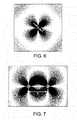
- FIG. 6shows an example of a resonant dielectric disk, and illustrates the surrounding field.
- FIG. 7shows a wireless energy transfer scheme featuring two resonant dielectric disks, and illustrates the surrounding field.
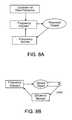
- FIGS. 8 a and 8 bshow schematics for frequency control mechanisms.
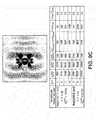
- FIGS. 9 a through 9 cillustrate a wireless energy transfer scheme in the presence of various extraneous objects.
- FIG. 10illustrates a circuit model for wireless energy transfer.
- FIG. 11illustrates the efficiency of a wireless energy transfer scheme.
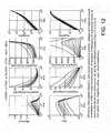
- FIG. 12illustrates parametric dependences of a wireless energy transfer scheme.
- FIG. 13plots the parametric dependences of a wireless energy transfer scheme.
- FIG. 14is a schematic of an experimental system demonstrating wireless energy transfer.
- FIGS. 15-17Plot experiment results for the system shown schematically in FIG. 14 .
- FIG. 1shows a schematic that generally describes one embodiment of the invention, in which energy is transferred wirelessly between two resonant objects.
- energyis transferred, over a distance D, between a resonant source object having a characteristic size L 1 and a resonant device object of characteristic size L 2 . Both objects are resonant objects.
- the source objectis connected to a power supply (not shown), and the device object is connected to a power consuming device (e.g. a load resistor, not shown).
- Energyis provided by the power supply to the source object, transferred wirelessly and non-radiatively from the source object to the device object, and consumed by the power consuming device.
- the wireless non-radiative energy transferis performed using the field (e.g. the electromagnetic field or acoustic field) of the system of two resonant objects. For simplicity, in the following we will assume that field is the electromagnetic field.
- a single source objectcan transfer energy to multiple device objects.
- multiple sourcescan transfer energy to one or more device objects.
- energymay be transferred from a first device to a second, and then from the second device to the third, and so forth.
- CMTCoupled-mode theory
- the field of the system of two resonant objects 1 and 2is approximated by F(r,t) ⁇ a 1 (t)F 1 (r) +a 2 (t)F 2 (r), where F 1,2 (r) are the eigenmodes of 1 and 2 alone, normalized to unity energy, and the field amplitudes a 1,2 (t) are defined so that
- ⁇ 1,2are the individual angular eigenfrequencies of the eigenmodes
- ⁇ 1,2are the resonance widths due to the objects' intrinsic (absorption, radiation etc.) losses
- ⁇is the coupling coefficient
- finite objectsnamely ones that are topologically surrounded everywhere by air
- the limiting surface, where this change in the field behavior happens,is called the “radiation caustic”, and, for the wireless energy-transfer scheme to be based on the near field rather than the far/radiation field, the distance between the coupled objects must be such that one lies within the radiation caustic of the other.
- the resonant source-objectwill be immobile and thus less restricted in its allowed geometry and size, which can be therefore chosen large enough that the near-field extent is not limited by the wavelength.
- Objects of nearly infinite extentsuch as dielectric waveguides, can support guided modes whose evanescent tails are decaying exponentially in the direction away from the object, slowly if tuned close to cutoff, and can have nearly infinite Q.
- this figure of meritis typically maximized when ⁇ 1,2 are tuned to a particular angular frequency ⁇ tilde over ( ⁇ ) ⁇ , thus, if ⁇ tilde over ( ⁇ ) ⁇ is half the angular-frequency width for which ⁇ square root over (Q 1 Q 2 ) ⁇ /Q ⁇ is above half its maximum value at ⁇ tilde over ( ⁇ ) ⁇ , the angular eigenfrequencies ⁇ 1,2 should typically be tuned to be close to ⁇ tilde over ( ⁇ ) ⁇ to within the width ⁇ tilde over ( ⁇ ) ⁇ .
- Q 1,2can sometimes be limited not from intrinsic loss mechanisms but from external perturbations. In those cases, producing a desirable figure-of-merit translates to reducing Q ⁇ (i.e. increasing the coupling). Accordingly we will demonstrate how, for particular embodiments, to reduce Q ⁇ .
- one or more of the resonant objectsare self-resonant conducting coils.
- the wirehas distributed inductance and distributed capacitance, and therefore it supports a resonant mode of angular frequency ⁇ .
- the nature of the resonancelies in the periodic exchange of energy from the electric field within the capacitance of the coil, due to the charge distribution ⁇ (x) across it, to the magnetic field in free space, due to the current distribution j(x) in the wire.
- Losses in this resonant systemconsist of ohmic (material absorption) loss inside the wire and radiative loss into free space.
- ohmicmaterial absorption
- R absa total absorption resistance from the amount of power absorbed inside the wire
- R rada total radiation resistance from the amount of power radiated due to electric- and magnetic-dipole radiation
- energyis transferred between two self-resonant conducting-wire coils.
- the electric and magnetic fieldsare used to couple the different resonant conducting-wire coils at a distance D between their centers.
- the electric couplinghighly dominates over the magnetic coupling in the system under consideration for coils with h>>2r and, oppositely, the magnetic coupling highly dominates over the electric coupling for coils with h ⁇ 2r.
- one or more of the resonant objectsare capacitively-loaded conducting loops or coils.
- the presence of the loading capacitormodifies significantly the current distribution inside the wire and therefore the total effective inductance L and total effective capacitance C of the coil are different respectively from L s and C s , which are calculated for a self-resonant coil of the same geometry using a sinusoidal current profile. Since some charge is accumulated at the plates of the external loading capacitor, the charge distribution ⁇ inside the wire is reduced, so C ⁇ C s , and thus, from the charge conservation equation, the current distribution j flattens out, so L>L s .
- ⁇ ⁇ ⁇[ c 4 ⁇ ⁇ ⁇ o 2 ⁇ ⁇ ⁇ ⁇ 1 aNr 3 ] 2 / 7 , ( 7 ) reaching the value
- a coil with large hcan be used, if the self-capacitance needs to be reduced compared to the external capacitance, but then the formulas for L and ⁇ tilde over ( ⁇ ) ⁇ , ⁇ tilde over (Q) ⁇ are again less accurate. Similar qualitative behavior is expected, but a more complicated theoretical model is needed for making quantitative predictions in that case.
- energyis transferred between two capacitively-loaded coils.
- the mutual inductance M Lcan be evaluated numerically from Eq. (6) by using constant current distributions in the case ⁇ s .
- the couplingis only magnetic and again we have an analytical formula, which, in the quasi-static limit r ⁇ D ⁇ and for the relative orientation shown in FIG.
- the optimal frequency ⁇ tilde over ( ⁇ ) ⁇is that where ⁇ square root over (Q 1 Q 2 ) ⁇ is maximized, since Q ⁇ does not depend on frequency (at least for the distances D ⁇ of interest for which the quasi-static approximation is still valid). Therefore, the optimal frequency is independent of the distance D between the two coils and lies between the two frequencies where the single-coil Q 1 and Q 2 peak. For same coils, it is given by Eq. (7) and then the figure-of-merit Eq. (9) becomes
- the results abovecan be used to increase or optimize the performance of a wireless energy transfer system which employs capacitively-loaded coils.
- the scaling of Eq. (10) with the different system parameters one sees that to maximize the system figure-of-merit ⁇ / ⁇ onecan, for example:
- the device under considerationis very specific (e.g. a laptop or a cell phone), so the dimensions of the device object (r d , h d , a d , N d ) are very restricted.
- the restrictions on the source object (r s , h s , a s , N s )are much less, since the source can, for example, be placed under the floor or on the ceiling.
- the desired distanceis often well defined, based on the application (e.g. D ⁇ 1 m for charging a laptop on a table wirelessly from the floor).
- the quality factor Q of the resonant objectsis limited from external perturbations and thus varying the coil parameters cannot lead to improvement in Q.
- the couplingdoes not depend on the frequency and the number of turns. Therefore, the remaining degrees of freedom are:
- Capacitively-loaded conducting loopsare currently used as resonant antennas (for example in cell phones), but those operate in the far-field regime with D/r>>1, r/ ⁇ ⁇ 1, and the radiation Q's are intentionally designed to be small to make the antenna efficient, so they are not appropriate for energy transfer.
- a straight conducting rod of length 2h and cross-sectional radius ahas distributed capacitance and distributed inductance, and therefore it supports a resonant mode of angular frequency ⁇ .
- ⁇an effective total inductance
- Can effective total capacitance
- one or more of the resonant objectsare inductively-loaded conducting rods.
- a straight conducting rod of length 2h and cross-sectional radius aas in the previous paragraph, is cut into two equal pieces of length h, which are connected via a coil wrapped around a magnetic material of relative permeability ⁇ , and everything is surrounded by air.
- the coilhas an inductance L c , which is added to the distributed inductance of the rod and thus modifies its resonance.
- the presence of the center-loading inductormodifies significantly the current distribution inside the wire and therefore the total effective inductance L and total effective capacitance C of the rod are different respectively from L s and C s , which are calculated for a self-resonant rod of the same total length using a sinusoidal current profile, as in the previous paragraph. Since some current is running inside the coil of the external loading inductor, the current distribution j inside the rod is reduced, so L ⁇ L s , and thus, from the charge conservation equation, the linear charge distribution ⁇ l flattens out towards the center (being positive in one side of the rod and negative in the other side of the rod, changing abruptly through the inductor), so C>C s .
- the inductoris made of a Brooks coil, which is the coil geometry which, for fixed wire length, demonstrates the highest inductance and thus quality factor.
- the Brooks coil geometryhas N Bc turns of conducting wire of cross-sectional radius a Bc wrapped around a cylindrically symmetric coil former, which forms a coil with a square cross-section of side r Bc , where the inner side of the square is also at radius r BC (and thus the outer side of the square is at radius 2r Bc ), therefore N Bc ⁇ (r Bc /2a Bc ).
- the external loading inductance L cprovides the freedom to tune the resonant frequency.
- the resonant frequencycan be reduced by increasing the number of turns N Bc by decreasing the wire cross-sectional radius a Bc .
- energyis transferred between two inductively-loaded rods.
- the mutual capacitance M ccan be evaluated numerically from Eq. (6) by using triangular current distributions in the case ⁇ s .
- the couplingis only electric and again we have an analytical formula, which, in the quasi-static limit h ⁇ D ⁇ and for the relative orientation such that the two rods are aligned on the same axis, is 1/M C ⁇ square root over (1/2) ⁇ 0 ⁇ (h 1 h 2 ) 2 /D 3 , which means that Q ⁇ ⁇ (D/ ⁇ square root over (h 1 h 2 ) ⁇ ) 3 is independent of the frequency ⁇ . Consequently, one can get the resultant coupling figure-of-merit of interest
- the optimal frequency ⁇ tilde over ( ⁇ ) ⁇is that where ⁇ square root over (Q 1 Q 2 ) ⁇ is maximized, since Q ⁇ does not depend on frequency (at least for the distances D ⁇ of interest for which the quasi-static approximation is still valid). Therefore, the optimal frequency is independent of the distance D between the two rods and lies between the two frequencies where the single-rod Q 1 and Q 2 peak.
- one or more of the resonant objectsare dielectric objects, such as disks.
- dielectric objectssuch as disks.
- a two dimensional dielectric disk objectas shown in FIG. 6 , of radius r and relative permittivity ⁇ surrounded by air that supports high-Q “whispering-gallery”resonant modes.
- the loss mechanisms for the energy stored inside such a resonant systemare radiation into free space and absorption inside the disk material.
- High-Q rad and long-tailed subwavelength resonancescan be achieved when the dielectric permittivity ⁇ is large and the azimuthal field variations are slow (namely of small principal number m).
- Material absorptionis related to the material loss tangent: Q abs ⁇ Re ⁇ /Im ⁇ .
- Mode-solving calculations for this type of disk resonanceswere performed using two independent methods: numerically, 2D finite-difference frequency-domain (FDFD) simulations (which solve Maxwell's Equations in frequency domain exactly apart for spatial discretization) were conducted with a resolution of 30 pts/r; analytically, standard separation of variables (SV) in polar coordinates was used.
- FDFDfinite-difference frequency-domain
- ⁇shown in Table 7, might at first seem unrealistically large. However, not only are there in the microwave regime (appropriate for approximately meter-range coupling applications) many materials that have both reasonably high enough dielectric constants and low losses (e.g. Titania, Barium tetratitanate, Lithium tantalite etc.), but also ⁇ could signify instead the effective index of other known subwavelength surface-wave systems, such as surface modes on surfaces of metallic materials or plasmonic (metal-like, negative- ⁇ ) materials or metallo-dielectric photonic crystals or plasmono-dielectric photonic crystals.
- plasmonicmetal-like, negative- ⁇
- any system that supports an electromagnetic mode with its electromagnetic energy extending much further than its sizecan be used for transferring energy.
- the overall performance of particular embodiment of the resonance-based wireless energy-transfer schemedepends strongly on the robustness of the resonant objects' resonances. Therefore, it is desirable to analyze the resonant objects' sensitivity to the near presence of random non-resonant extraneous objects.
- One appropriate analytical modelis that of “perturbation theory” (PT), which suggests that in the presence of an extraneous object e the field amplitude a 1 (t) inside the resonant object 1 satisfies, to first order:
- ⁇ 1is the frequency and ⁇ 1 the intrinsic (absorption, radiation etc.) loss rate
- ⁇ 11-eis the frequency shift induced onto 1 due to the presence of e
- ⁇ 1-eis the extrinsic due to e (absorption inside e, scattering from e etc.) loss rate.
- the first-order PT modelis valid only for small perturbations.
- the parameters ⁇ 11-e , ⁇ 1-eare well defined, even outside that regime, if a 1 is taken to be the amplitude of the exact perturbed mode. Note also that interference effects between the radiation field of the initial resonant-object mode and the field scattered off the extraneous object can for strong scattering (e.g. off metallic objects) result in total radiation— ⁇ 1-e 's that are smaller than the initial radiation— ⁇ 1 (namely ⁇ 1-e is negative).
- each resonant objectis provided with an oscillator at fixed frequency and a monitor which determines the frequency of the object. Both the oscillator and the monitor are coupled to a frequency adjuster which can adjust the frequency of the resonant object by, for example, adjusting the geometric properties of the object (e.g.
- the frequency adjusterdetermines the difference between the fixed frequency and the object frequency and acts to bring the object frequency into alignment with the fixed frequency. This technique assures that all resonant objects operate at the same fixed frequency, even in the presence of extraneous objects.
- the device objectduring energy transfer from a source object to a device object, the device object provides energy to a load, and an efficiency monitor measures the efficiency of the transfer.
- a frequency adjuster coupled to the load and the efficiency monitoracts to adjust the frequency of the object to maximize the transfer efficiency.
- frequency adjusting schemesmay be used which rely on information exchange between the resonant objects.
- the frequency of a source objectcan be monitored and transmitted to a device object, which is in turn synched to this frequency using frequency adjusters as described above.
- the frequency of a single clockmay be transmitted to multiple devices, and each device then synched to that frequency.
- extraneous non-conducting objects e that could interact with this field and act as a perturbation to the resonanceare those having significant magnetic properties (magnetic permeability Re ⁇ >1 or magnetic loss Im ⁇ >0). Since almost all every-day non-conducting materials are non-magnetic but just dielectric, they respond to magnetic fields in the same way as free space, and thus will not disturb the resonance of the resonator. Extraneous conducting materials can however lead to some extrinsic losses due to the eddy currents induced on their surface.
- Self-resonant coilsare more sensitive than capacitively-loaded coils, since for the former the electric field extends over a much larger region in space (the entire coil) rather than for the latter (just inside the capacitor).
- self-resonant coilsare simple to make and can withstand much larger voltages than most lumped capacitors.
- resonant systemshave different degree of sensitivity to external perturbations, and the resonant system of choice depends on the particular application at hand, and how important matters of sensitivity or safety are for that application.
- a medical implantable devicesuch as a wirelessly powered artificial heart
- the electric field extentmust be minimized to the highest degree possible to protect the tissue surrounding the device.
- sensitivity to external objects or safetyis important, one should design the resonant systems so that the ratio of electric to magnetic energy density u e /u m is reduced or minimized at most of the desired (according to the application) points in the surrounding space.
- This difference in scalinggives us confidence that, for, for example, exponentially small field tails, coupling to other resonant objects should be much faster than all extrinsic loss rates ( ⁇ >> ⁇ 1-e ), at least for small perturbations, and thus the energy-transfer scheme is expected to be sturdy for this class of resonant dielectric disks.
- Inductively-loaded conducting rodsmay also be more sensitive than capacitively-loaded coils, since they rely on the electric field to achieve the coupling.
- Different temporal schemescan be used to extract power from the device (e.g.
- the reactive powerswhich are usually present in a system and circulate stored energy around it, cancel at resonance (which can be proven for example in electromagnetism from Poynting's Theorem) and do not influence the power-balance calculations.
- the working efficiencyis then:
- the dimensions of the resonant objectswill be set by the particular application at hand. For example, when this application is powering a laptop or a cell-phone, the device resonant object cannot have dimensions larger that those of the laptop or cell-phone respectively.
- the independent parameters left to adjust for the system optimizationare: the number of turns N s,d , the frequency f, the work-extraction rate (load resistance) ⁇ work and the power-supply feeding rate ⁇ supply .
- the primary dependent variable that one wants to increase or optimizeis the overall efficiency ⁇ .
- the designmay be constrained by, for example, the currents flowing inside the wires I s,d and the voltages across the capacitors V s,d . These limitations can be important because for ⁇ Watt power applications the values for these parameters can be too large for the wires or the capacitors respectively to handle.
- the total loaded Q tot⁇ L d /(R d +R w ) of the device is a quantity that should be preferably small, because to match the source and device resonant frequencies to within their Q's, when those are very large, can be challenging experimentally and more sensitive to slight variations.
- the radiated powers P rad,s,dshould be minimized for safety concerns, even though, in general, for a magnetic, non-radiative scheme they are already typically small.
- the increased inductance L dimplies reduced required capacitance C d , which could be achieved in principle, for a capacitively-loaded device coil by increasing the spacing of the device capacitor plates d d and for a self-resonant coil by increasing through h d the spacing of adjacent turns, resulting in an electric field ( ⁇ V d /d d for the former case) that actually decreases with N d ; however, one cannot in reality increase d d or h d too much, because then the undesired capacitance fringing electric fields would become very large and/or the size of the coil might become too large; and, in any case, for certain applications extremely high voltages are not desired.
- FIGS. 12 and 13and the just above calculated performance characteristics are made using the analytical formulas provided above, so they are expected to be less accurate for large values of N s , N d , still they give a good estimate of the scalings and the orders of magnitude.
- An experimental realization of an embodiment of the above described scheme for wireless energy transferconsists of two self-resonant coils of the type described above, one of which (the source coil) is coupled inductively to an oscillating circuit, and the second (the device coil) is coupled inductively to a resistive load, as shown schematically in FIG. 14 .
- Ais a single copper loop of radius 25 cm that is part of the driving circuit, which outputs a sine wave with frequency 9.9 MHz.
- s and dare respectively the source and device coils referred to in the text.
- Bis a loop of wire attached to the load (“light-bulb”).
- the various ⁇ 'srepresent direct couplings between the objects.
- the angle between coil d and the loop Ais adjusted so that their direct coupling is zero, while coils s and d are aligned coaxially.
- the direct coupling between B and A and between B and sis negligible.
- the coupling coefficient ⁇can be found experimentally by placing the two self-resonant coils (fine-tuned, by slightly adjusting h, to the same resonant frequency when isolated) a distance D apart and measuring the splitting in the frequencies of the two resonant modes in the transmission spectrum.
- FIG. 15The comparison between experimental and theoretical results as a function of distance when the two the coils are aligned coaxially is shown in FIG. 15 .
- FIG. 16shows a comparison of experimental and theoretical values for the parameter ⁇ / ⁇ as a function of the separation between the two coils.
- the theory valuesare obtained by using the theoretically obtained ⁇ and the experimentally measured ⁇ .
- the shaded arearepresents the spread in the theoretical ⁇ / ⁇ due to the ⁇ 5% uncertainty in Q.
- the power supply circuitwas a standard Colpitts oscillator coupled inductively to the source coil by means of a single loop of copper wire 25 cm in radius (see FIG. 14 ).
- the loadconsisted of a previously calibrated light-bulb, and was attached to its own loop of insulated wire, which was in turn placed in proximity of the device coil and inductively coupled to it.
- the parameter ⁇ work / ⁇was adjusted so that it matched its optimal value, given theoretically by ⁇ square root over (1+ ⁇ 2 /( ⁇ 1 ⁇ 2 )) ⁇ .
- the loop connected to the light-bulbadded a small reactive component to ⁇ work which was compensated for by slightly retuning the coil.
- the work extractedwas determined by adjusting the power going into the Colpitts oscillator until the light-bulb at the load was at its full nominal brightness.
- the power transferwas not found to be visibly affected as humans and various everyday objects, such as metallic and wooden furniture, as well as electronic devices large and small, were placed between the two coils, even when they drastically obstructed the line of sight between source and device. External objects were found to have an effect only when they were closer than 10 cm from either one of the coils. While some materials (such as aluminum foil, styrofoam and humans) mostly just shifted the resonant frequency, which could in principle be easily corrected with a feedback circuit of the type described earlier, others (cardboard, wood, and PVC) lowered Q when placed closer than a few centimeters from the coil, thereby lowering the efficiency of the transfer.
- materialssuch as aluminum foil, styrofoam and humans
- the two coilsare currently of identical dimensions, it is possible to make the device coil small enough to fit into portable devices without decreasing the efficiency. One could, for instance, maintain the product of the characteristic sizes of the source and device coils constant.
- this schemecould potentially be used to deliver power to for example, robots and/or computers in a factory room, or electric buses on a highway.
- source-objectcould be an elongated “pipe” running above the highway, or along the ceiling.
- Some embodiments of the wireless transfer schemecan provide energy to power or charge devices that are difficult or impossible to reach using wires or other techniques.
- some embodimentsmay provide power to implanted medical devices (e.g. artificial hearts, pacemakers, medicine delivery pumps, etc.) or buried underground sensors.
- CMOS electronicsIn the microscopic world, where much smaller wavelengths would be used and smaller powers are needed, one could use it to implement optical inter-connects for CMOS electronics, or to transfer energy to autonomous nano-objects (e.g. MEMS or nano-robots) without worrying much about the relative alignment between the sources and the devices. Furthermore, the range of applicability could be extended to acoustic systems, where the source and device are connected via a common condensed-matter object.
- nano-objectse.g. MEMS or nano-robots
- the techniques described abovecan provide non-radiative wireless transfer of information using the localized near fields of resonant object. Such schemes provide increased security because no information is radiated into the far-field, and are well suited for mid-range communication of highly sensitive information.
Landscapes
- Engineering & Computer Science (AREA)
- Computer Networks & Wireless Communication (AREA)
- Power Engineering (AREA)
- Transportation (AREA)
- Mechanical Engineering (AREA)
- Signal Processing (AREA)
- Control Of Motors That Do Not Use Commutators (AREA)
- Electric Propulsion And Braking For Vehicles (AREA)
- Current-Collector Devices For Electrically Propelled Vehicles (AREA)
- Magnetic Resonance Imaging Apparatus (AREA)
Abstract
Description
In some such embodiments, D/L2may be as large as 2, as large as 3, as large as 5, as large as 7, or as large as 10.
In some such embodiments, D/L2may be as large as 2, as large as 3, as large as 5, as large as 7, as large as 10.
In some such embodiments D/LRis as large as about 2, 3, 5, or 8.
In some such embodiments D/LRis as large as about 3, 5, 7, or 10.
In some such embodiments D/LRis as large as about 3, 5, 7, or 10.
In some such embodiments, D/LRis as large as about 3, about 5, about 7, or about 10.
In some such embodiments, D/LRis as large as about 3, about 5, about 7, or about 10.
In some such embodiments, D/LRis as large as about 3, about 5, about 7, or about 10.
In some such embodiments, D/LRis as large as about 3, about 5, about 7, or about 10.
In some such embodiments, D/LRis as large as about 3, about 5, about 7, or about 10.
is less than about 5 Amps/√{square root over (Watts)} or less than about 2 Amps/√{square root over (Watts)}. In some embodiments, during operation, one of the resonator structures receives a usable power Pwfrom the other resonator structure, a voltage difference Vsappears across the capacitive element of the first resonator structure, and the ratio
is less than about 2000 Volts/√{square root over (Watts)} or less than about 4000 Volts/√{square root over (Watts)}.
In some such embodiments, D/LRis as large as about 3, about 5, about 7, or about 10.
In some such embodiments, D/LRis as large as about 3, about 5, about 7, or about 10.
In some such embodiments, D/LRis as large as about 3, about 5, about 7, or about 10.
In some such embodiments, D/LRis as large as about 3, about 5, about 7.
In some such embodiments, D/L2may be as large as 2, as large as 3, as large as 5, as large as 7, or as large as 10.
In some such embodiments, D/L2may be as large as 2, as large as 3, as large as 5, as large as 7, or as large as 10.
In some such embodiments, D/L2may be as large as 2, as large as 3, as large as 5, as large as 7, or as large as 10.
is maximized, all other factors held constant.
where ω1,2are the individual angular eigenfrequencies of the eigenmodes, Γ1,2are the resonance widths due to the objects' intrinsic (absorption, radiation etc.) losses, and κ is the coupling coefficient. Eqs. (1) show that at exact resonance (ω1=ω2and Γ1=Γ2), the eigenmodes of the combined system are split by 2κ; the energy exchange between the two objects takes place in time ˜π/2Γ and is nearly perfect, apart for losses, which are minimal when the coupling rate is much faster than all loss rates (κ>>Γ1,2). The coupling to loss ratio κ/√{square root over (Γ1Γ2)} serves as a figure-of-merit in evaluating a system used for wireless energy-transfer, along with the distance over which this ratio can be achieved. The regime κ/√{square root over (Γ1Γ2)}>>1 is called “strong-coupling” regime.
is the maximum amount of positive charge accumulated in one side of the coil (where an equal amount of negative charge always also accumulates in the other side to make the system neutral) and I0=max{|I(x)|} is the maximum positive value of the linear current distribution, then I0=ωq0. Then, one can define an effective total inductance L and an effective total capacitance C of the coil through the amount of energy U inside its resonant mode:
where μ0and ε0are the magnetic permeability and electric permittivity of free space. With these definitions, the resonant angular frequency and the effective impedance are given by the common formulas ω=1/√{square root over (LC)} and Z=√{square root over (L/C)} respectively.
where c=1/√{square root over (μ0ε0)} and ζ0=√{square root over (μ0/ε0)} are the light velocity and light impedance in free space, the impedance ζcis ζc=1/σδ=√{square root over (μ0ω/2σ)} with σ the conductivity of the conductor and δ the skin depth at the frequency
is the electric-dipole moment of the coil and
is the magnetic-dipole moment of the coil. For the radiation resistance formula Eq. (5), the assumption of operation in the quasi-static regime (h,r<<λ=2πc/ω) has been used, which is the desired regime of a subwavelength resonance. With these definitions, the absorption and radiation quality factors of the resonance are given by Qabs=Z/Rabsand Qrad=Z/Rradrespectively.
Using these sinusoidal profiles we find the so-called “self-inductance” Lsand “self-capacitance” Csof the coil by computing numerically the integrals Eq. (2) and (3); the associated frequency and effective impedance are ωsand Zsrespectively. The “self-resistances” Rsare given analytically by Eq. (4) and (5) using
and therefore the associated Qsfactors may be calculated.
| TABLE 1 | |||||
| single coil | λs/r | f (MHz) | Qsrad | Qsabs | Qs= ωs/2Γs |
| r = 30 cm, h = 20 cm, | 74.7 | 13.39 | 4164 | 8170 | 2758 |
| a = 1 cm, N = 4 | |||||
| r = 10 cm, h = 3 cm, | 140 | 21.38 | 43919 | 3968 | 3639 |
| a = 2 mm, N = 6 | |||||
and the retardation factor of u=exp(iω|x−x′|/c) inside the integral can been ignored in the quasi-static regime D<<λ of interest, where each coil is within the near field of the other. With this definition, the coupling coefficient is given by κ=ω√{square root over (C1C2)}/2MC+ωML/2√{square root over (L1L2)}

| TABLE 2 | ||||
| pair of coils | D/r | Q = ω/2Γ | Qκ = ω/2κ | κ/Γ |
| r = 30 cm, h = 20 cm, | 3 | 2758 | 38.9 | 70.9 |
| a = 1 cm, N = 4 | 5 | 2758 | 139.4 | 19.8 |
| λ/r ≈ 75 | 7 | 2758 | 333.0 | 8.3 |
| Qsabs≈ 8170, Qsrad≈ 4164 | 10 | 2758 | 818.9 | 3.4 |
| r = 10 cm, h = 3 cm, | 3 | 3639 | 61.4 | 59.3 |
| a = 2 mm, N = 6 | 5 | 3639 | 232.5 | 15.7 |
| λ/r ≈ 140 | 7 | 3639 | 587.5 | 6.2 |
| Qsabs≈ 3968, Qsrad≈ 43919 | 10 | 3639 | 1580 | 2.3 |
ω=1/√{square root over (L(C+Cp))}<ωs=1/√{square root over (LsCs)}, andI(x)→I0cos(πx/l)

reaching the value
At lower frequencies it is dominated by ohmic loss and at higher frequencies by radiation. Note, however, that the formulas above are accurate as long as {tilde over (ω)}<<ωsand, as explained above, this holds almost always when N=1, and is usually less accurate when N>1, since h=0 usually implies a large self-capacitance. A coil with large h can be used, if the self-capacitance needs to be reduced compared to the external capacitance, but then the formulas for L and {tilde over (ω)}, {tilde over (Q)} are again less accurate. Similar qualitative behavior is expected, but a more complicated theoretical model is needed for making quantitative predictions in that case.
| TABLE 3 | |||||
| single coil | λ/r | f (MHz) | Qrad | Qabs | Q = ω/2Γ |
| r = 30 cm , a = 2 cm | 111.4 (112.4) | 8.976 (8.897) | 29546 (30512) | 4886 (5117) | 4193 (4381) |
| ∈ = 10, A = 138 | |||||
| r = 10 cm, a = 2 mm | 69.7 (70.4) | 43.04 (42.61) | 10702 (10727) | 1545 (1604) | 1350 (1395) |
| ∈ = 10, A = 3.14 cm2, d = 1 mm | |||||
which again is more accurate for N1=N2=1.

Typically, one should tune the capacitively-loaded conducting loops or coils, so that their angular eigenfrequencies are close to {tilde over (ω)} within {tilde over (Γ)}, which is half the angular frequency width for which √{square root over (Q1Q2)}/Qκ>

| TABLE 4 | |||||
| pair of coils | D/r | Qrad | Q = ω/2Γ | Qκ= ω/2κ | κ/Γ |
| r = 30 cm, a = 2 | 3 | 30729 | 4216 | 62.6 (63.7) | 67.4 (68.7) |
| ε = 10, A = 138 | 5 | 29577 | 4194 | 235 (248) | 17.8 (17.6) |
| λ/r ≈ 112 | 7 | 29128 | 4185 | 589 (646) | 7.1 (6.8) |
| Qabs≈ 4886 | 10 | 28833 | 4177 | 1539 (1828) | 2.7 (2.4) |
| r = 10 cm, a = 2 | 3 | 10955 | 1355 | 85.4 (91.3) | 15.9 (15.3) |
| ε = 10, A = 3.14 cm2, d = 1 | 5 | 10740 | 1351 | 313 (356) | 4.32 (3.92) |
| λ/r ≈ 70 | 7 | 10759 | 1351 | 754 (925) | 1.79 (1.51) |
| Qabs≈ 1546 | 10 | 10756 | 1351 | 1895 (2617) | 0.71 (0.53) |
- Decrease the resistivity of the conducting material. This can be achieved, for example, by using good conductors (such as copper or silver) and/or lowering the temperature. At very low temperatures one could use also superconducting materials to achieve extremely good performance.
- Increase the wire radius a. In typical embodiments, this action is limited by physical size considerations. The purpose of this action is mainly to reduce the resistive losses in the wire by increasing the cross-sectional area through which the electric current is flowing, so one could alternatively use also a Litz wire or a ribbon instead of a circular wire.
- For fixed desired distance D of energy transfer, increase the radius of the loop r. In typical embodiments, this action is limited by physical size considerations.
- For fixed desired distance vs. loop-size ratio D/r, decrease the radius of the loop r. In typical embodiments, this action is limited by physical size considerations.
- Increase the number of turns N. (Even though Eq. (10) is expected to be less accurate for N>1, qualitatively it still provides a good indication that we expect an improvement in the coupling-to-loss ratio with increased N.) In typical embodiments, this action is limited by physical size and possible voltage considerations, as will be discussed in following sections.
- Adjust the alignment and orientation between the two coils. The figure-of-merit is optimized when both cylindrical coils have exactly the same axis of cylindrical symmetry (namely they are “facing” each other). In some embodiments, particular mutual coil angles and orientations that lead to zero mutual inductance (such as the orientation where the axes of the two coils are perpendicular) should be avoided.
- Finally, note that the height of the coil h is another available design parameter, which has an impact to the performance similar to that of its radius r, and thus the design rules are similar.
D/r=5, κ/Γ≧10, r=30 cm
D/r=5, κ/Γ≧10, r=5 cm
D/r=5, κ/Γ≧20, r=30 cm
D/r=5, κ/Γ≧20, r=5 cm
D/r=10, κ/Γ≧1, r=30 cm
D/r=10, κ/Γ≧1, r=5 cm
D/r=10, κ/Γ≧3, r=30 cm
D/r=10, κ/Γ≧3, r=5 cm
D=1.5 m, κ/√{square root over (ΓsΓd)}≧15, rd=30 cm,ad=6 mm
D=1.5 m, κ/√{square root over (ΓsΓd)}≧30, rd=30 cm,ad=6 mm
D=1.5 m, κ/√{square root over (ΓsΓd)}≧1, rd=5 cm,ad=4 mm
D=1.5 m, κ/√{square root over (ΓsΓd)}≧2, rd=5 cm,ad=4 mm
D=2 m, κ/√{square root over (ΓsΓd)}≧10, rd=30 cm,ad=6 mm
D=2 m, κ/√{square root over (ΓsΓd)}≧20,rd=30 cm,ad=6 mm
D=2 m, κ/√{square root over (ΓsΓd)}≧0.5,rd=5 cm,ad=4 mm
D=2 m, κ/√{square root over (ΓsΓd)}≧1,rd=5 cm,ad=4 mm
- Increase the wire radii a1and a2. In typical embodiments, this action is limited by physical size considerations.
- For fixed desired distance D of energy transfer, increase the radii of the coils r1and r2. In typical embodiments, this action is limited by physical size considerations.
- For fixed desired distance vs. coil-sizes ratio D/√{square root over (r1r2)}, only the weak (logarithmic) dependence of the inductance remains, which suggests that one should decrease the radii of the coils r1and r2. In typical embodiments, this action is limited by physical size considerations.
- Adjust the alignment and orientation between the two coils. In typical embodiments, the coupling is optimized when both cylindrical coils have exactly the same axis of cylindrical symmetry (namely they are “facing” each other). Particular mutual coil angles and orientations that lead to zero mutual inductance (such as the orientation where the axes of the two coils are perpendicular) should obviously be avoided.
- Finally, note that the heights of the coils h1and h2are other available design parameters, which have an impact to the coupling similar to that of their radii r1and r2, and thus the design rules are similar.
ω=1/√{square root over ((L+Lc)C)}<ωs=1/√{square root over (LsCs)}, andI(x)→I0cos(πx/2h)
where the total wire length is lBc≈2π(3rBc/2)NBc≈3πrBc3/4aBc2and we have used an approximate square-root law for the transition of the resistance from the dc to the ac limit as the skin depth varies with frequency.
Then, for the particular simple case Lc>>Ls, for which we have analytical formulas, the total Q=1/ωC(Rc+Rabs+Rrad) becomes highest at some optimal frequency {tilde over (ω)}, reaching the value {tilde over (Q)}, both determined by the loading-inductor specific design. (For example, for the Brooks-coil procedure described above, at the optimal frequency {tilde over (Q)}≈Qc≈0.8(μ0σ2rBc3/C)1/4) At lower frequencies it is dominated by ohmic loss inside the inductor coil and at higher frequencies by radiation. Note, again, that the above formulas are accurate as long as {tilde over (ω)}<<ωsand, as explained above, this is easy to design for by using a large inductance.
| TABLE 5 | |||||
| single rod | λ/h | f (MHz) | Qrad | Qabs | Q = ω/2Γ |
| h = 30 cm, | (403.8) | (2.477) | (2.72 * 106) | (7400) | (7380) |
| a = 2 cm | |||||
| μ = 1, | |||||
| rBc= 2 cm, | |||||
| aBc= 0.88 mm, | |||||
| NBc= 129 | |||||
| h = 10 cm, | (214.2) | (14.010) | (6.92 * 105) | (3908) | (3886) |
| a = 2 mm | |||||
| μ = 1, | |||||
| rBc= 5 mm, | |||||
| aBc= 0.25 mm, | |||||
It can be seen that the optimal frequency {tilde over (ω)}, where the figure-of-merit is maximized to the value


| TABLE 6 | |||
| pair of rods | D/h | Qκ = ω/2κ | κ/Γ |
| h = 30 cm, a = 2 cm | 3 | (70.3) | (105.0) |
| μ = 1, rBc= 2 cm, | 5 | (389) | (19.0) |
| aBc= 0.88 mm, NBc= 129 | 7 | (1115) | (6.62) |
| λ/h ≈ 404 | 10 | (3321) | (2.22) |
| Q ≈ 7380 | |||
| h = 10 cm, a = 2 mm | 3 | (120) | (32.4) |
| μ = 1, rBc= 5 mm, | 5 | (664) | (5.85) |
| aBc= 0.25 mm, NBc= 103 | 7 | (1900) | (2.05) |
| λ/h ≈ 214 | 10 | (5656) | (0.69) |
| Q ≈ 3886 | |||
| TABLE 7 | ||||
| single | ||||
| disk | λ/r | Qabs | Qrad | Q |
| Re{ε} = | 20.01 (20.00) | 10103 (10075) | 1988 (1992) | 1661 (1663) |
| 147.7, | ||||
| m = 2 | ||||
| Re{ε} = | 9.952 (9.950) | 10098 (10087) | 9078 (9168) | 4780 (4802) |
| 65.6, | ||||
| m = 3 | ||||
The results for two TE-polarized dielectric-disk subwavelength modes of λ/r≧10 are presented in Table 7. Table 7 shows numerical FDFD (and in parentheses analytical SV) results for the wavelength and absorption, radiation and total loss rates, for two different cases of subwavelength-disk resonant modes. Note that disk-material loss-tangent Im{ε}/Re{ε}=10−4was used. (The specific parameters corresponding to the plot in
| TABLE 8 | |||||
| two disks | D/r | Qrad | Q = ω/2Γ | ω/2κ | κ/Γ |
| Re{ε} = 147.7, | 3 | 2478 | 1989 | 46.9 (47.5) | 42.4 (35.0) |
| m = 2 | 5 | 2411 | 1946 | 298.0 (298.0) | 6.5 (5.6) |
| λ/r ≈ 20 | 7 | 2196 | 1804 | 769.7 (770.2) | 2.3 (2.2) |
| Qabs≈ 10093 | 10 | 2017 | 1681 | 1714 (1601) | 0.98 (1.04) |
| Re{ε} = 65.6, | 3 | 7972 | 4455 | 144 (140) | 30.9 (34.3) |
| m = 3 | 5 | 9240 | 4824 | 2242 (2083) | 2.2 (2.3) |
| λ/r ≈ 10 | 7 | 9187 | 4810 | 7485 (7417) | 0.64 (0.65) |
| Qabs≈ 10096 | |||||
where again ω1is the frequency and Γ1the intrinsic (absorption, radiation etc.) loss rate, while κ11-eis the frequency shift induced onto 1 due to the presence of e and Γ1-eis the extrinsic due to e (absorption inside e, scattering from e etc.) loss rate. The first-order PT model is valid only for small perturbations. Nevertheless, the parameters κ11-e, Γ1-eare well defined, even outside that regime, if a1is taken to be the amplitude of the exact perturbed mode. Note also that interference effects between the radiation field of the initial resonant-object mode and the field scattered off the extraneous object can for strong scattering (e.g. off metallic objects) result in total radiation—Γ1-e's that are smaller than the initial radiation—Γ1(namely Γ1-eis negative).
where the second line is the ratio of averages over all angles by integrating the electric and magnetic energy densities over the surface of a sphere of radius Dp. From Eq. (12) it is obvious that indeed for all angles in the near field (x<<1) the magnetic energy density is dominant, while in the far field (x>>1) they are equal as they should be. Also, the preferred positioning of the loop is such that objects which may interfere with its resonance lie close to its axis (θ=0), where there is no electric field. For example, using the systems described in Table 4, we can estimate from Eq. (12) that for the loop of r=30 cm at a distance Dp=10r=3 m the ratio of average electric to average magnetic energy density would be ˜12% and at Dp=3r=90 cm it would be ˜1%, and for the loop of r=10 cm at a distance Dp=10r=1 m the ratio would be ˜33% and at Dp=3r=30 cm it would be ˜2.5%. At closer distances this ratio is even smaller and thus the energy is predominantly magnetic in the near field, while in the radiative far field, where they are necessarily of the same order (ratio→1), both are very small, because the fields have significantly decayed, as capacitively-loaded coil systems are designed to radiate very little. Therefore, this is the criterion that qualifies this class of resonant system as a magnetic resonant system.
Γ1-erad=ω1∫d3rRe{εe(r)}|E1(r)|2/U
and
Γ1-eabs=ω1/4·∫d3rIm{εe(r)}|E1(r)|2/U
where U=½∫d3rε(r)|E1(r)|2is the total resonant electromagnetic energy of the unperturbed mode. As one can see, both of these losses depend on the square of the resonant electric field tails E1 at the site of the extraneous object. In contrast, the coupling rate from
κ=ω1/2·∫d3rε2(r)E2*(r)E1(r)/∫d3rε(r)|E1(r)|2
and depends linearly on the field tails E1 of1 inside2. This difference in scaling gives us confidence that, for, for example, exponentially small field tails, coupling to other resonant objects should be much faster than all extrinsic loss rates (κ>>Γ1-e), at least for small perturbations, and thus the energy-transfer scheme is expected to be sturdy for this class of resonant dielectric disks. However, we also want to examine certain possible situations where extraneous objects cause perturbations too strong to analyze using the above first-order perturbation theory approach. For example, we place a dielectric disk c close to another off-resonance object of large Re{ε}, Im{ε} and of same size but different shape (such as a human being h), as shown in
where Γd[e]=Γd[e]rad+Γd[e]abs=Γd[e]rad+(Γdabs+Γd-eabs) is the net perturbed-device loss rate, and similarly we define Γs[e] for the perturbed-source. Different temporal schemes can be used to extract power from the device (e.g. steady-state continuous-wave drainage, instantaneous drainage at periodic times and so on) and their efficiencies exhibit different dependence on the combined system parameters. For simplicity, we assume steady state, such that the field amplitude inside the source is maintained constant, namely as(t)=Ase−iωt, so then the field amplitude inside the device is ad(t)=Ade−iωtwith Ad/As=iκ[e]/(Γd[e]+Γwork). The various time-averaged powers of interest are then: the useful extracted power is Pwork=2Γwork|Ad|2, the radiated (including scattered) power is Prad=2Γs[e]rad|As|2+2Γd[e]rad|Ad|2, the power absorbed at the source/device is Ps/d=2Γs/dabs|As/d|2, and at the extraneous objects Pe=2Γs-eabs|As|2+2Γd-eabs|Ad|2. From energy conservation, the total time-averaged power entering the system is Ptotal=Pwork+Prad+Ps+Pd+Pe. Note that the reactive powers, which are usually present in a system and circulate stored energy around it, cancel at resonance (which can be proven for example in electromagnetism from Poynting's Theorem) and do not influence the power-balance calculations. The working efficiency is then:
where fom[e]=κ[e]/√{square root over (Γs[e]Γd[e])} is the distance-dependent figure-of-merit of the perturbed resonant energy-exchange system. To derive Eq. (14), we have assumed that the rate Γsupply, at which the power supply is feeding energy to the resonant source, is Γsupply=Γs[e]+κ2/(Γd[e]+Γwork), such that there are zero reflections of the fed power Ptotalback into the power supply.
and from the device circuit at resonance (ωLd=1/ωCd):
0=Id(Rd+Rw)−jωMIs
So by substituting the second to the first:
Now we take the real part (time-averaged powers) to find the efficiency:
which with Γwork=Rω/2Ld, Γd=Rd/2Ld, Γs=Rs/2Ls, and Γ=ωM/2√{square root over (LsLd)}, becomes the general Eq. (14). [End of Example]
required for given output power Pworkcan be achieved with smaller currents. However, increasing Ndincreases Qtot, Prad,dand the voltage across the device capacitance Vd, which unfortunately ends up being, in typical embodiments one of the greatest limiting factors of the system. To explain this, note that it is the electric field that really induces breakdown of the capacitor material (e.g. 3 kV/mm for air) and not the voltage, and that for the desired (close to the optimal) operational frequency, the increased inductance Ldimplies reduced required capacitance Cd, which could be achieved in principle, for a capacitively-loaded device coil by increasing the spacing of the device capacitor plates ddand for a self-resonant coil by increasing through hdthe spacing of adjacent turns, resulting in an electric field (≈Vd/ddfor the former case) that actually decreases with Nd; however, one cannot in reality increase ddor hdtoo much, because then the undesired capacitance fringing electric fields would become very large and/or the size of the coil might become too large; and, in any case, for certain applications extremely high voltages are not desired. A similar increasing behavior is observed for the source Prad,sand Vsupon increasing Ns. As a conclusion, the number of turns Nsand Ndhave to be chosen the largest possible (for efficiency) that allow for reasonable voltages, fringing electric fields and physical sizes.
Claims (39)
Priority Applications (11)
| Application Number | Priority Date | Filing Date | Title |
|---|---|---|---|
| US12/437,641US8097983B2 (en) | 2005-07-12 | 2009-05-08 | Wireless energy transfer |
| US12/949,504US20110074218A1 (en) | 2005-07-12 | 2010-11-18 | Wireless energy transfer |
| US12/949,544US20110074347A1 (en) | 2005-07-12 | 2010-11-18 | Wireless energy transfer |
| US12/949,580US20110089895A1 (en) | 2005-07-12 | 2010-11-18 | Wireless energy transfer |
| US13/036,177US20110193419A1 (en) | 2005-07-12 | 2011-02-28 | Wireless energy transfer |
| US13/477,459US9444265B2 (en) | 2005-07-12 | 2012-05-22 | Wireless energy transfer |
| US13/789,860US9509147B2 (en) | 2005-07-12 | 2013-03-08 | Wireless energy transfer |
| US14/666,683US9450422B2 (en) | 2005-07-12 | 2015-03-24 | Wireless energy transfer |
| US15/186,969US10097044B2 (en) | 2005-07-12 | 2016-06-20 | Wireless energy transfer |
| US16/137,795US20190123586A1 (en) | 2005-07-12 | 2018-09-21 | Wireless energy transfer |
| US17/009,041US11685270B2 (en) | 2005-07-12 | 2020-09-01 | Wireless energy transfer |
Applications Claiming Priority (7)
| Application Number | Priority Date | Filing Date | Title |
|---|---|---|---|
| US69844205P | 2005-07-12 | 2005-07-12 | |
| US11/481,077US7741734B2 (en) | 2005-07-12 | 2006-07-05 | Wireless non-radiative energy transfer |
| US90838307P | 2007-03-27 | 2007-03-27 | |
| US90866607P | 2007-03-28 | 2007-03-28 | |
| PCT/US2007/070892WO2008118178A1 (en) | 2007-03-27 | 2007-06-11 | Wireless energy transfer |
| US12/055,963US7825543B2 (en) | 2005-07-12 | 2008-03-26 | Wireless energy transfer |
| US12/437,641US8097983B2 (en) | 2005-07-12 | 2009-05-08 | Wireless energy transfer |
Related Parent Applications (1)
| Application Number | Title | Priority Date | Filing Date |
|---|---|---|---|
| US12/055,963ContinuationUS7825543B2 (en) | 2005-07-12 | 2008-03-26 | Wireless energy transfer |
Related Child Applications (4)
| Application Number | Title | Priority Date | Filing Date |
|---|---|---|---|
| US12/949,504ContinuationUS20110074218A1 (en) | 2005-07-12 | 2010-11-18 | Wireless energy transfer |
| US12/949,544ContinuationUS20110074347A1 (en) | 2005-07-12 | 2010-11-18 | Wireless energy transfer |
| US12/949,580ContinuationUS20110089895A1 (en) | 2005-07-12 | 2010-11-18 | Wireless energy transfer |
| US13/036,177ContinuationUS20110193419A1 (en) | 2005-07-12 | 2011-02-28 | Wireless energy transfer |
Publications (2)
| Publication Number | Publication Date |
|---|---|
| US20090224856A1 US20090224856A1 (en) | 2009-09-10 |
| US8097983B2true US8097983B2 (en) | 2012-01-17 |
Family
ID=46330224
Family Applications (42)
| Application Number | Title | Priority Date | Filing Date |
|---|---|---|---|
| US12/055,963Active2027-07-21US7825543B2 (en) | 2005-07-12 | 2008-03-26 | Wireless energy transfer |
| US12/437,641Active2027-09-18US8097983B2 (en) | 2005-07-12 | 2009-05-08 | Wireless energy transfer |
| US12/688,339AbandonedUS20100117456A1 (en) | 2005-07-12 | 2010-01-15 | Applications of wireless energy transfer using coupled antennas |
| US12/708,850AbandonedUS20100237706A1 (en) | 2005-07-12 | 2010-02-19 | Wireless power system and proximity effects |
| US12/713,556AbandonedUS20100237707A1 (en) | 2005-07-12 | 2010-02-26 | Increasing the q factor of a resonator |
| US12/717,559AbandonedUS20100253152A1 (en) | 2005-07-12 | 2010-03-04 | Long range low frequency resonator |
| US12/726,742AbandonedUS20100171370A1 (en) | 2005-07-12 | 2010-03-18 | Maximizing power yield from wireless power magnetic resonators |
| US12/726,913AbandonedUS20100264745A1 (en) | 2005-07-12 | 2010-03-18 | Resonators for wireless power applications |
| US12/726,953AbandonedUS20100181844A1 (en) | 2005-07-12 | 2010-03-18 | High efficiency and power transfer in wireless power magnetic resonators |
| US12/732,399AbandonedUS20100237708A1 (en) | 2005-07-12 | 2010-03-26 | Transmitters and receivers for wireless energy transfer |
| US12/766,232AbandonedUS20100201205A1 (en) | 2005-07-12 | 2010-04-23 | Biological effects of magnetic power transfer |
| US12/784,615AbandonedUS20100225175A1 (en) | 2005-07-12 | 2010-05-21 | Wireless power bridge |
| US12/787,765AbandonedUS20100231053A1 (en) | 2005-07-12 | 2010-05-26 | Wireless power range increase using parasitic resonators |
| US12/837,675AbandonedUS20100277005A1 (en) | 2005-07-12 | 2010-07-16 | Wireless powering and charging station |
| US12/862,907AbandonedUS20110049996A1 (en) | 2005-07-12 | 2010-08-25 | Wireless desktop it environment |
| US12/868,852AbandonedUS20100327660A1 (en) | 2005-07-12 | 2010-08-26 | Resonators and their coupling characteristics for wireless power transfer via magnetic coupling |
| US12/879,263AbandonedUS20110012431A1 (en) | 2005-07-12 | 2010-09-10 | Resonators for wireless power transfer |
| US12/879,395AbandonedUS20100327661A1 (en) | 2005-07-12 | 2010-09-10 | Packaging and details of a wireless power device |
| US12/896,400AbandonedUS20110025131A1 (en) | 2005-07-12 | 2010-10-01 | Packaging and details of a wireless power device |
| US12/896,328AbandonedUS20110018361A1 (en) | 2005-07-12 | 2010-10-01 | Tuning and gain control in electro-magnetic power systems |
| US12/939,400AbandonedUS20110049998A1 (en) | 2005-07-12 | 2010-11-04 | Wireless delivery of power to a fixed-geometry power part |
| US12/949,544AbandonedUS20110074347A1 (en) | 2005-07-12 | 2010-11-18 | Wireless energy transfer |
| US12/949,580AbandonedUS20110089895A1 (en) | 2005-07-12 | 2010-11-18 | Wireless energy transfer |
| US12/949,504AbandonedUS20110074218A1 (en) | 2005-07-12 | 2010-11-18 | Wireless energy transfer |
| US13/030,395AbandonedUS20110140544A1 (en) | 2005-07-12 | 2011-02-18 | Adaptive wireless power transfer apparatus and method thereof |
| US13/030,400AbandonedUS20110148219A1 (en) | 2005-07-12 | 2011-02-18 | Short range efficient wireless power transfer |
| US13/036,177AbandonedUS20110193419A1 (en) | 2005-07-12 | 2011-02-28 | Wireless energy transfer |
| US13/040,810AbandonedUS20110198939A1 (en) | 2005-07-12 | 2011-03-04 | Flat, asymmetric, and e-field confined wireless power transfer apparatus and method thereof |
| US13/051,098AbandonedUS20110169339A1 (en) | 2005-07-12 | 2011-03-18 | Method and apparatus of load detection for a planar wireless power system |
| US13/051,153AbandonedUS20110162895A1 (en) | 2005-07-12 | 2011-03-18 | Noncontact electric power receiving device, noncontact electric power transmitting device, noncontact electric power feeding system, and electrically powered vehicle |
| US13/078,511AbandonedUS20110181122A1 (en) | 2005-07-12 | 2011-04-01 | Wirelessly powered speaker |
| US13/102,498AbandonedUS20120248884A1 (en) | 2005-07-12 | 2011-05-06 | Wireless power transmission apparatus |
| US13/107,293AbandonedUS20110227528A1 (en) | 2005-07-12 | 2011-05-13 | Adaptive matching, tuning, and power transfer of wireless power |
| US13/112,476AbandonedUS20110221278A1 (en) | 2005-07-12 | 2011-05-20 | Power supply system and method of controlling power supply system |
| US13/116,474AbandonedUS20110227530A1 (en) | 2005-07-12 | 2011-05-26 | Wireless power transmission for portable wireless power charging |
| US13/163,020AbandonedUS20110241618A1 (en) | 2005-07-12 | 2011-06-17 | Methods and systems for wireless power transmission |
| US13/477,459Active2028-06-27US9444265B2 (en) | 2005-07-12 | 2012-05-22 | Wireless energy transfer |
| US13/789,860Active2026-12-20US9509147B2 (en) | 2005-07-12 | 2013-03-08 | Wireless energy transfer |
| US14/666,683ActiveUS9450422B2 (en) | 2005-07-12 | 2015-03-24 | Wireless energy transfer |
| US15/186,969Active2026-12-25US10097044B2 (en) | 2005-07-12 | 2016-06-20 | Wireless energy transfer |
| US16/137,795AbandonedUS20190123586A1 (en) | 2005-07-12 | 2018-09-21 | Wireless energy transfer |
| US17/009,041ActiveUS11685270B2 (en) | 2005-07-12 | 2020-09-01 | Wireless energy transfer |
Family Applications Before (1)
| Application Number | Title | Priority Date | Filing Date |
|---|---|---|---|
| US12/055,963Active2027-07-21US7825543B2 (en) | 2005-07-12 | 2008-03-26 | Wireless energy transfer |
Family Applications After (40)
| Application Number | Title | Priority Date | Filing Date |
|---|---|---|---|
| US12/688,339AbandonedUS20100117456A1 (en) | 2005-07-12 | 2010-01-15 | Applications of wireless energy transfer using coupled antennas |
| US12/708,850AbandonedUS20100237706A1 (en) | 2005-07-12 | 2010-02-19 | Wireless power system and proximity effects |
| US12/713,556AbandonedUS20100237707A1 (en) | 2005-07-12 | 2010-02-26 | Increasing the q factor of a resonator |
| US12/717,559AbandonedUS20100253152A1 (en) | 2005-07-12 | 2010-03-04 | Long range low frequency resonator |
| US12/726,742AbandonedUS20100171370A1 (en) | 2005-07-12 | 2010-03-18 | Maximizing power yield from wireless power magnetic resonators |
| US12/726,913AbandonedUS20100264745A1 (en) | 2005-07-12 | 2010-03-18 | Resonators for wireless power applications |
| US12/726,953AbandonedUS20100181844A1 (en) | 2005-07-12 | 2010-03-18 | High efficiency and power transfer in wireless power magnetic resonators |
| US12/732,399AbandonedUS20100237708A1 (en) | 2005-07-12 | 2010-03-26 | Transmitters and receivers for wireless energy transfer |
| US12/766,232AbandonedUS20100201205A1 (en) | 2005-07-12 | 2010-04-23 | Biological effects of magnetic power transfer |
| US12/784,615AbandonedUS20100225175A1 (en) | 2005-07-12 | 2010-05-21 | Wireless power bridge |
| US12/787,765AbandonedUS20100231053A1 (en) | 2005-07-12 | 2010-05-26 | Wireless power range increase using parasitic resonators |
| US12/837,675AbandonedUS20100277005A1 (en) | 2005-07-12 | 2010-07-16 | Wireless powering and charging station |
| US12/862,907AbandonedUS20110049996A1 (en) | 2005-07-12 | 2010-08-25 | Wireless desktop it environment |
| US12/868,852AbandonedUS20100327660A1 (en) | 2005-07-12 | 2010-08-26 | Resonators and their coupling characteristics for wireless power transfer via magnetic coupling |
| US12/879,263AbandonedUS20110012431A1 (en) | 2005-07-12 | 2010-09-10 | Resonators for wireless power transfer |
| US12/879,395AbandonedUS20100327661A1 (en) | 2005-07-12 | 2010-09-10 | Packaging and details of a wireless power device |
| US12/896,400AbandonedUS20110025131A1 (en) | 2005-07-12 | 2010-10-01 | Packaging and details of a wireless power device |
| US12/896,328AbandonedUS20110018361A1 (en) | 2005-07-12 | 2010-10-01 | Tuning and gain control in electro-magnetic power systems |
| US12/939,400AbandonedUS20110049998A1 (en) | 2005-07-12 | 2010-11-04 | Wireless delivery of power to a fixed-geometry power part |
| US12/949,544AbandonedUS20110074347A1 (en) | 2005-07-12 | 2010-11-18 | Wireless energy transfer |
| US12/949,580AbandonedUS20110089895A1 (en) | 2005-07-12 | 2010-11-18 | Wireless energy transfer |
| US12/949,504AbandonedUS20110074218A1 (en) | 2005-07-12 | 2010-11-18 | Wireless energy transfer |
| US13/030,395AbandonedUS20110140544A1 (en) | 2005-07-12 | 2011-02-18 | Adaptive wireless power transfer apparatus and method thereof |
| US13/030,400AbandonedUS20110148219A1 (en) | 2005-07-12 | 2011-02-18 | Short range efficient wireless power transfer |
| US13/036,177AbandonedUS20110193419A1 (en) | 2005-07-12 | 2011-02-28 | Wireless energy transfer |
| US13/040,810AbandonedUS20110198939A1 (en) | 2005-07-12 | 2011-03-04 | Flat, asymmetric, and e-field confined wireless power transfer apparatus and method thereof |
| US13/051,098AbandonedUS20110169339A1 (en) | 2005-07-12 | 2011-03-18 | Method and apparatus of load detection for a planar wireless power system |
| US13/051,153AbandonedUS20110162895A1 (en) | 2005-07-12 | 2011-03-18 | Noncontact electric power receiving device, noncontact electric power transmitting device, noncontact electric power feeding system, and electrically powered vehicle |
| US13/078,511AbandonedUS20110181122A1 (en) | 2005-07-12 | 2011-04-01 | Wirelessly powered speaker |
| US13/102,498AbandonedUS20120248884A1 (en) | 2005-07-12 | 2011-05-06 | Wireless power transmission apparatus |
| US13/107,293AbandonedUS20110227528A1 (en) | 2005-07-12 | 2011-05-13 | Adaptive matching, tuning, and power transfer of wireless power |
| US13/112,476AbandonedUS20110221278A1 (en) | 2005-07-12 | 2011-05-20 | Power supply system and method of controlling power supply system |
| US13/116,474AbandonedUS20110227530A1 (en) | 2005-07-12 | 2011-05-26 | Wireless power transmission for portable wireless power charging |
| US13/163,020AbandonedUS20110241618A1 (en) | 2005-07-12 | 2011-06-17 | Methods and systems for wireless power transmission |
| US13/477,459Active2028-06-27US9444265B2 (en) | 2005-07-12 | 2012-05-22 | Wireless energy transfer |
| US13/789,860Active2026-12-20US9509147B2 (en) | 2005-07-12 | 2013-03-08 | Wireless energy transfer |
| US14/666,683ActiveUS9450422B2 (en) | 2005-07-12 | 2015-03-24 | Wireless energy transfer |
| US15/186,969Active2026-12-25US10097044B2 (en) | 2005-07-12 | 2016-06-20 | Wireless energy transfer |
| US16/137,795AbandonedUS20190123586A1 (en) | 2005-07-12 | 2018-09-21 | Wireless energy transfer |
| US17/009,041ActiveUS11685270B2 (en) | 2005-07-12 | 2020-09-01 | Wireless energy transfer |
Country Status (1)
| Country | Link |
|---|---|
| US (42) | US7825543B2 (en) |
Cited By (200)
| Publication number | Priority date | Publication date | Assignee | Title |
|---|---|---|---|---|
| US20100096934A1 (en)* | 2005-07-12 | 2010-04-22 | Joannopoulos John D | Wireless energy transfer with high-q similar resonant frequency resonators |
| US20100148589A1 (en)* | 2008-10-01 | 2010-06-17 | Hamam Rafif E | Efficient near-field wireless energy transfer using adiabatic system variations |
| US20110043049A1 (en)* | 2008-09-27 | 2011-02-24 | Aristeidis Karalis | Wireless energy transfer with high-q resonators using field shaping to improve k |
| US20110074347A1 (en)* | 2005-07-12 | 2011-03-31 | Aristeidis Karalis | Wireless energy transfer |
| US20110074346A1 (en)* | 2009-09-25 | 2011-03-31 | Hall Katherine L | Vehicle charger safety system and method |
| US20110169336A1 (en)* | 2010-01-13 | 2011-07-14 | Yerazunis William S | Wireless Energy Transfer to Moving Devices |
| US20120049986A1 (en)* | 2010-08-25 | 2012-03-01 | Electronics And Telecommunications Research Institute | Apparatus for reducing electric field and radiation field in magnetic resonant coupling coils or magnetic induction device for wireless energy transfer |
| US20120153732A1 (en)* | 2008-09-27 | 2012-06-21 | Kurs Andre B | Wireless energy transfer for computer peripheral applications |
| US8304935B2 (en) | 2008-09-27 | 2012-11-06 | Witricity Corporation | Wireless energy transfer using field shaping to reduce loss |
| US8324759B2 (en) | 2008-09-27 | 2012-12-04 | Witricity Corporation | Wireless energy transfer using magnetic materials to shape field and reduce loss |
| US8410636B2 (en) | 2008-09-27 | 2013-04-02 | Witricity Corporation | Low AC resistance conductor designs |
| US8441154B2 (en) | 2008-09-27 | 2013-05-14 | Witricity Corporation | Multi-resonator wireless energy transfer for exterior lighting |
| US8461722B2 (en) | 2008-09-27 | 2013-06-11 | Witricity Corporation | Wireless energy transfer using conducting surfaces to shape field and improve K |
| US8461721B2 (en) | 2008-09-27 | 2013-06-11 | Witricity Corporation | Wireless energy transfer using object positioning for low loss |
| US8461719B2 (en) | 2008-09-27 | 2013-06-11 | Witricity Corporation | Wireless energy transfer systems |
| US8461720B2 (en) | 2008-09-27 | 2013-06-11 | Witricity Corporation | Wireless energy transfer using conducting surfaces to shape fields and reduce loss |
| US8466583B2 (en) | 2008-09-27 | 2013-06-18 | Witricity Corporation | Tunable wireless energy transfer for outdoor lighting applications |
| US8471410B2 (en) | 2008-09-27 | 2013-06-25 | Witricity Corporation | Wireless energy transfer over distance using field shaping to improve the coupling factor |
| US8476788B2 (en) | 2008-09-27 | 2013-07-02 | Witricity Corporation | Wireless energy transfer with high-Q resonators using field shaping to improve K |
| US8482158B2 (en) | 2008-09-27 | 2013-07-09 | Witricity Corporation | Wireless energy transfer using variable size resonators and system monitoring |
| US8487480B1 (en) | 2008-09-27 | 2013-07-16 | Witricity Corporation | Wireless energy transfer resonator kit |
| US8497601B2 (en) | 2008-09-27 | 2013-07-30 | Witricity Corporation | Wireless energy transfer converters |
| US8552592B2 (en) | 2008-09-27 | 2013-10-08 | Witricity Corporation | Wireless energy transfer with feedback control for lighting applications |
| US8569914B2 (en) | 2008-09-27 | 2013-10-29 | Witricity Corporation | Wireless energy transfer using object positioning for improved k |
| US8587155B2 (en) | 2008-09-27 | 2013-11-19 | Witricity Corporation | Wireless energy transfer using repeater resonators |
| US8587153B2 (en) | 2008-09-27 | 2013-11-19 | Witricity Corporation | Wireless energy transfer using high Q resonators for lighting applications |
| US8598743B2 (en) | 2008-09-27 | 2013-12-03 | Witricity Corporation | Resonator arrays for wireless energy transfer |
| US8629578B2 (en) | 2008-09-27 | 2014-01-14 | Witricity Corporation | Wireless energy transfer systems |
| US8643326B2 (en) | 2008-09-27 | 2014-02-04 | Witricity Corporation | Tunable wireless energy transfer systems |
| US8667452B2 (en) | 2011-11-04 | 2014-03-04 | Witricity Corporation | Wireless energy transfer modeling tool |
| US8669676B2 (en) | 2008-09-27 | 2014-03-11 | Witricity Corporation | Wireless energy transfer across variable distances using field shaping with magnetic materials to improve the coupling factor |
| US8686598B2 (en) | 2008-09-27 | 2014-04-01 | Witricity Corporation | Wireless energy transfer for supplying power and heat to a device |
| US8692412B2 (en) | 2008-09-27 | 2014-04-08 | Witricity Corporation | Temperature compensation in a wireless transfer system |
| US8692410B2 (en) | 2008-09-27 | 2014-04-08 | Witricity Corporation | Wireless energy transfer with frequency hopping |
| US8723366B2 (en) | 2008-09-27 | 2014-05-13 | Witricity Corporation | Wireless energy transfer resonator enclosures |
| US8729737B2 (en) | 2008-09-27 | 2014-05-20 | Witricity Corporation | Wireless energy transfer using repeater resonators |
| US8772973B2 (en) | 2008-09-27 | 2014-07-08 | Witricity Corporation | Integrated resonator-shield structures |
| US8805530B2 (en) | 2007-06-01 | 2014-08-12 | Witricity Corporation | Power generation for implantable devices |
| US8847548B2 (en) | 2008-09-27 | 2014-09-30 | Witricity Corporation | Wireless energy transfer for implantable devices |
| US8901778B2 (en) | 2008-09-27 | 2014-12-02 | Witricity Corporation | Wireless energy transfer with variable size resonators for implanted medical devices |
| US8901779B2 (en) | 2008-09-27 | 2014-12-02 | Witricity Corporation | Wireless energy transfer with resonator arrays for medical applications |
| US8907531B2 (en) | 2008-09-27 | 2014-12-09 | Witricity Corporation | Wireless energy transfer with variable size resonators for medical applications |
| US8912687B2 (en) | 2008-09-27 | 2014-12-16 | Witricity Corporation | Secure wireless energy transfer for vehicle applications |
| US8922066B2 (en) | 2008-09-27 | 2014-12-30 | Witricity Corporation | Wireless energy transfer with multi resonator arrays for vehicle applications |
| US8928276B2 (en) | 2008-09-27 | 2015-01-06 | Witricity Corporation | Integrated repeaters for cell phone applications |
| US8933594B2 (en) | 2008-09-27 | 2015-01-13 | Witricity Corporation | Wireless energy transfer for vehicles |
| US8937408B2 (en) | 2008-09-27 | 2015-01-20 | Witricity Corporation | Wireless energy transfer for medical applications |
| US8946938B2 (en) | 2008-09-27 | 2015-02-03 | Witricity Corporation | Safety systems for wireless energy transfer in vehicle applications |
| US8947186B2 (en) | 2008-09-27 | 2015-02-03 | Witricity Corporation | Wireless energy transfer resonator thermal management |
| US8957549B2 (en) | 2008-09-27 | 2015-02-17 | Witricity Corporation | Tunable wireless energy transfer for in-vehicle applications |
| US8963488B2 (en) | 2008-09-27 | 2015-02-24 | Witricity Corporation | Position insensitive wireless charging |
| US9030161B2 (en) | 2011-06-27 | 2015-05-12 | Board Of Regents, The University Of Texas System | Wireless power transmission |
| US9035499B2 (en) | 2008-09-27 | 2015-05-19 | Witricity Corporation | Wireless energy transfer for photovoltaic panels |
| US9065423B2 (en) | 2008-09-27 | 2015-06-23 | Witricity Corporation | Wireless energy distribution system |
| US9093853B2 (en) | 2008-09-27 | 2015-07-28 | Witricity Corporation | Flexible resonator attachment |
| US9105959B2 (en) | 2008-09-27 | 2015-08-11 | Witricity Corporation | Resonator enclosure |
| US9106203B2 (en) | 2008-09-27 | 2015-08-11 | Witricity Corporation | Secure wireless energy transfer in medical applications |
| US9160203B2 (en) | 2008-09-27 | 2015-10-13 | Witricity Corporation | Wireless powered television |
| US9184595B2 (en) | 2008-09-27 | 2015-11-10 | Witricity Corporation | Wireless energy transfer in lossy environments |
| US9246336B2 (en) | 2008-09-27 | 2016-01-26 | Witricity Corporation | Resonator optimizations for wireless energy transfer |
| US9261870B2 (en) | 2012-10-30 | 2016-02-16 | Vikrant Sharma | Control system for power transmission within a structure |
| US9287607B2 (en) | 2012-07-31 | 2016-03-15 | Witricity Corporation | Resonator fine tuning |
| US9306635B2 (en) | 2012-01-26 | 2016-04-05 | Witricity Corporation | Wireless energy transfer with reduced fields |
| US9318257B2 (en) | 2011-10-18 | 2016-04-19 | Witricity Corporation | Wireless energy transfer for packaging |
| US9318922B2 (en) | 2008-09-27 | 2016-04-19 | Witricity Corporation | Mechanically removable wireless power vehicle seat assembly |
| US9343922B2 (en) | 2012-06-27 | 2016-05-17 | Witricity Corporation | Wireless energy transfer for rechargeable batteries |
| US9384885B2 (en) | 2011-08-04 | 2016-07-05 | Witricity Corporation | Tunable wireless power architectures |
| US9396867B2 (en) | 2008-09-27 | 2016-07-19 | Witricity Corporation | Integrated resonator-shield structures |
| US9396870B2 (en) | 2012-12-14 | 2016-07-19 | Samsung Electronics Co., Ltd. | Wireless power transmission devices, wireless power reception devices, wireless power transmission systems, and wireless power transmission methods |
| US9404954B2 (en) | 2012-10-19 | 2016-08-02 | Witricity Corporation | Foreign object detection in wireless energy transfer systems |
| US9421388B2 (en) | 2007-06-01 | 2016-08-23 | Witricity Corporation | Power generation for implantable devices |
| US9442172B2 (en) | 2011-09-09 | 2016-09-13 | Witricity Corporation | Foreign object detection in wireless energy transfer systems |
| US9449757B2 (en) | 2012-11-16 | 2016-09-20 | Witricity Corporation | Systems and methods for wireless power system with improved performance and/or ease of use |
| US9496921B1 (en) | 2015-09-09 | 2016-11-15 | Cpg Technologies | Hybrid guided surface wave communication |
| US9515494B2 (en) | 2008-09-27 | 2016-12-06 | Witricity Corporation | Wireless power system including impedance matching network |
| US9544683B2 (en) | 2008-09-27 | 2017-01-10 | Witricity Corporation | Wirelessly powered audio devices |
| US9577449B2 (en) | 2014-01-17 | 2017-02-21 | Honda Motor Co., Ltd. | Method and apparatus to align wireless charging coils |
| US9595378B2 (en) | 2012-09-19 | 2017-03-14 | Witricity Corporation | Resonator enclosure |
| US9601270B2 (en) | 2008-09-27 | 2017-03-21 | Witricity Corporation | Low AC resistance conductor designs |
| US9602168B2 (en) | 2010-08-31 | 2017-03-21 | Witricity Corporation | Communication in wireless energy transfer systems |
| US9601266B2 (en) | 2008-09-27 | 2017-03-21 | Witricity Corporation | Multiple connected resonators with a single electronic circuit |
| US9642219B2 (en) | 2014-06-05 | 2017-05-02 | Steelcase Inc. | Environment optimization for space based on presence and activities |
| US9685148B2 (en) | 2015-01-02 | 2017-06-20 | Fishman Transducers, Inc. | Method and device for wireless power source for an instrument |
| US9744858B2 (en) | 2008-09-27 | 2017-08-29 | Witricity Corporation | System for wireless energy distribution in a vehicle |
| US9780573B2 (en) | 2014-02-03 | 2017-10-03 | Witricity Corporation | Wirelessly charged battery system |
| US9796280B2 (en) | 2012-03-23 | 2017-10-24 | Hevo Inc. | Systems and mobile application for electric wireless charging stations |
| US9837860B2 (en) | 2014-05-05 | 2017-12-05 | Witricity Corporation | Wireless power transmission systems for elevators |
| US9842688B2 (en) | 2014-07-08 | 2017-12-12 | Witricity Corporation | Resonator balancing in wireless power transfer systems |
| US9842687B2 (en) | 2014-04-17 | 2017-12-12 | Witricity Corporation | Wireless power transfer systems with shaped magnetic components |
| US9843217B2 (en) | 2015-01-05 | 2017-12-12 | Witricity Corporation | Wireless energy transfer for wearables |
| US9852388B1 (en) | 2014-10-03 | 2017-12-26 | Steelcase, Inc. | Method and system for locating resources and communicating within an enterprise |
| US9857821B2 (en) | 2013-08-14 | 2018-01-02 | Witricity Corporation | Wireless power transfer frequency adjustment |
| US9859707B2 (en) | 2014-09-11 | 2018-01-02 | Cpg Technologies, Llc | Simultaneous multifrequency receive circuits |
| US9857402B2 (en) | 2015-09-08 | 2018-01-02 | CPG Technologies, L.L.C. | Measuring and reporting power received from guided surface waves |
| US9855376B2 (en) | 2014-07-25 | 2018-01-02 | Minnetronix, Inc. | Power scaling |
| US9871412B2 (en) | 2013-01-04 | 2018-01-16 | Samsung Electronics Co., Ltd. | Wireless power reception devices |
| US9882436B2 (en) | 2015-09-09 | 2018-01-30 | Cpg Technologies, Llc | Return coupled wireless power transmission |
| US9882397B2 (en) | 2014-09-11 | 2018-01-30 | Cpg Technologies, Llc | Guided surface wave transmission of multiple frequencies in a lossy media |
| US9887558B2 (en) | 2015-09-09 | 2018-02-06 | Cpg Technologies, Llc | Wired and wireless power distribution coexistence |
| US9885742B2 (en) | 2015-09-09 | 2018-02-06 | Cpg Technologies, Llc | Detecting unauthorized consumption of electrical energy |
| US9887587B2 (en) | 2014-09-11 | 2018-02-06 | Cpg Technologies, Llc | Variable frequency receivers for guided surface wave transmissions |
| US9887556B2 (en) | 2014-09-11 | 2018-02-06 | Cpg Technologies, Llc | Chemically enhanced isolated capacitance |
| US9887557B2 (en) | 2014-09-11 | 2018-02-06 | Cpg Technologies, Llc | Hierarchical power distribution |
| US9887585B2 (en) | 2015-09-08 | 2018-02-06 | Cpg Technologies, Llc | Changing guided surface wave transmissions to follow load conditions |
| US9893403B2 (en) | 2015-09-11 | 2018-02-13 | Cpg Technologies, Llc | Enhanced guided surface waveguide probe |
| US9892849B2 (en) | 2014-04-17 | 2018-02-13 | Witricity Corporation | Wireless power transfer systems with shield openings |
| US9893402B2 (en) | 2014-09-11 | 2018-02-13 | Cpg Technologies, Llc | Superposition of guided surface waves on lossy media |
| US9899718B2 (en) | 2015-09-11 | 2018-02-20 | Cpg Technologies, Llc | Global electrical power multiplication |
| US9912031B2 (en) | 2013-03-07 | 2018-03-06 | Cpg Technologies, Llc | Excitation and use of guided surface wave modes on lossy media |
| US9910144B2 (en) | 2013-03-07 | 2018-03-06 | Cpg Technologies, Llc | Excitation and use of guided surface wave modes on lossy media |
| US9916485B1 (en) | 2015-09-09 | 2018-03-13 | Cpg Technologies, Llc | Method of managing objects using an electromagnetic guided surface waves over a terrestrial medium |
| US9923385B2 (en) | 2015-06-02 | 2018-03-20 | Cpg Technologies, Llc | Excitation and use of guided surface waves |
| US9921726B1 (en) | 2016-06-03 | 2018-03-20 | Steelcase Inc. | Smart workstation method and system |
| US9921256B2 (en) | 2015-09-08 | 2018-03-20 | Cpg Technologies, Llc | Field strength monitoring for optimal performance |
| US9929721B2 (en) | 2015-10-14 | 2018-03-27 | Witricity Corporation | Phase and amplitude detection in wireless energy transfer systems |
| US9927477B1 (en) | 2015-09-09 | 2018-03-27 | Cpg Technologies, Llc | Object identification system and method |
| US9941566B2 (en) | 2014-09-10 | 2018-04-10 | Cpg Technologies, Llc | Excitation and use of guided surface wave modes on lossy media |
| US9948145B2 (en) | 2011-07-08 | 2018-04-17 | Witricity Corporation | Wireless power transfer for a seat-vest-helmet system |
| US9955318B1 (en) | 2014-06-05 | 2018-04-24 | Steelcase Inc. | Space guidance and management system and method |
| US9952266B2 (en) | 2014-02-14 | 2018-04-24 | Witricity Corporation | Object detection for wireless energy transfer systems |
| US9954375B2 (en) | 2014-06-20 | 2018-04-24 | Witricity Corporation | Wireless power transfer systems for surfaces |
| US9960470B2 (en) | 2014-09-11 | 2018-05-01 | Cpg Technologies, Llc | Site preparation for guided surface wave transmission in a lossy media |
| US9973037B1 (en) | 2015-09-09 | 2018-05-15 | Cpg Technologies, Llc | Object identification system and method |
| US9997040B2 (en) | 2015-09-08 | 2018-06-12 | Cpg Technologies, Llc | Global emergency and disaster transmission |
| US10001553B2 (en) | 2014-09-11 | 2018-06-19 | Cpg Technologies, Llc | Geolocation with guided surface waves |
| US10018744B2 (en) | 2014-05-07 | 2018-07-10 | Witricity Corporation | Foreign object detection in wireless energy transfer systems |
| US10027116B2 (en) | 2014-09-11 | 2018-07-17 | Cpg Technologies, Llc | Adaptation of polyphase waveguide probes |
| US10027177B2 (en) | 2015-09-09 | 2018-07-17 | Cpg Technologies, Llc | Load shedding in a guided surface wave power delivery system |
| US10027131B2 (en) | 2015-09-09 | 2018-07-17 | CPG Technologies, Inc. | Classification of transmission |
| US10031208B2 (en) | 2015-09-09 | 2018-07-24 | Cpg Technologies, Llc | Object identification system and method |
| US10033198B2 (en) | 2014-09-11 | 2018-07-24 | Cpg Technologies, Llc | Frequency division multiplexing for wireless power providers |
| US10033197B2 (en) | 2015-09-09 | 2018-07-24 | Cpg Technologies, Llc | Object identification system and method |
| US10063095B2 (en) | 2015-09-09 | 2018-08-28 | CPG Technologies, Inc. | Deterring theft in wireless power systems |
| US10062944B2 (en) | 2015-09-09 | 2018-08-28 | CPG Technologies, Inc. | Guided surface waveguide probes |
| US10063104B2 (en) | 2016-02-08 | 2018-08-28 | Witricity Corporation | PWM capacitor control |
| US10063110B2 (en) | 2015-10-19 | 2018-08-28 | Witricity Corporation | Foreign object detection in wireless energy transfer systems |
| US10069328B2 (en) | 2016-04-06 | 2018-09-04 | Powersphyr Inc. | Intelligent multi-mode wireless power system |
| US10074993B2 (en) | 2014-09-11 | 2018-09-11 | Cpg Technologies, Llc | Simultaneous transmission and reception of guided surface waves |
| US10075019B2 (en) | 2015-11-20 | 2018-09-11 | Witricity Corporation | Voltage source isolation in wireless power transfer systems |
| US10079573B2 (en) | 2014-09-11 | 2018-09-18 | Cpg Technologies, Llc | Embedding data on a power signal |
| US10084223B2 (en) | 2014-09-11 | 2018-09-25 | Cpg Technologies, Llc | Modulated guided surface waves |
| US10101444B2 (en) | 2014-09-11 | 2018-10-16 | Cpg Technologies, Llc | Remote surface sensing using guided surface wave modes on lossy media |
| US10103452B2 (en) | 2015-09-10 | 2018-10-16 | Cpg Technologies, Llc | Hybrid phased array transmission |
| US10122218B2 (en) | 2015-09-08 | 2018-11-06 | Cpg Technologies, Llc | Long distance transmission of offshore power |
| US10128697B1 (en) | 2017-05-01 | 2018-11-13 | Hevo, Inc. | Detecting and deterring foreign objects and living objects at wireless charging stations |
| US10135301B2 (en) | 2015-09-09 | 2018-11-20 | Cpg Technologies, Llc | Guided surface waveguide probes |
| US10141788B2 (en) | 2015-10-22 | 2018-11-27 | Witricity Corporation | Dynamic tuning in wireless energy transfer systems |
| US10141622B2 (en) | 2015-09-10 | 2018-11-27 | Cpg Technologies, Llc | Mobile guided surface waveguide probes and receivers |
| US10149933B2 (en) | 2014-07-25 | 2018-12-11 | Minnetronix, Inc. | Coil parameters and control |
| US10161752B1 (en) | 2014-10-03 | 2018-12-25 | Steelcase Inc. | Method and system for locating resources and communicating within an enterprise |
| US10175203B2 (en) | 2014-09-11 | 2019-01-08 | Cpg Technologies, Llc | Subsurface sensing using guided surface wave modes on lossy media |
| US10175048B2 (en) | 2015-09-10 | 2019-01-08 | Cpg Technologies, Llc | Geolocation using guided surface waves |
| US10193595B2 (en) | 2015-06-02 | 2019-01-29 | Cpg Technologies, Llc | Excitation and use of guided surface waves |
| US10193229B2 (en) | 2015-09-10 | 2019-01-29 | Cpg Technologies, Llc | Magnetic coils having cores with high magnetic permeability |
| US10193395B2 (en) | 2015-04-14 | 2019-01-29 | Minnetronix, Inc. | Repeater resonator |
| US10205326B2 (en) | 2015-09-09 | 2019-02-12 | Cpg Technologies, Llc | Adaptation of energy consumption node for guided surface wave reception |
| US10230270B2 (en) | 2015-09-09 | 2019-03-12 | Cpg Technologies, Llc | Power internal medical devices with guided surface waves |
| US10248899B2 (en) | 2015-10-06 | 2019-04-02 | Witricity Corporation | RFID tag and transponder detection in wireless energy transfer systems |
| US10264213B1 (en) | 2016-12-15 | 2019-04-16 | Steelcase Inc. | Content amplification system and method |
| US10263473B2 (en) | 2016-02-02 | 2019-04-16 | Witricity Corporation | Controlling wireless power transfer systems |
| US10312747B2 (en) | 2015-09-10 | 2019-06-04 | Cpg Technologies, Llc | Authentication to enable/disable guided surface wave receive equipment |
| US10324163B2 (en) | 2015-09-10 | 2019-06-18 | Cpg Technologies, Llc | Geolocation using guided surface waves |
| US10342908B2 (en) | 2015-01-14 | 2019-07-09 | Minnetronix, Inc. | Distributed transformer |
| US10353664B2 (en) | 2014-03-07 | 2019-07-16 | Steelcase Inc. | Method and system for facilitating collaboration sessions |
| US10369894B2 (en) | 2016-10-21 | 2019-08-06 | Hevo, Inc. | Parking alignment sequence for wirelessly charging an electric vehicle |
| US10396446B2 (en) | 2013-05-28 | 2019-08-27 | University Of Florida Research Foundation, Inc. | Dual function helix antenna |
| US10396566B2 (en) | 2015-09-10 | 2019-08-27 | Cpg Technologies, Llc | Geolocation using guided surface waves |
| US10406267B2 (en) | 2015-01-16 | 2019-09-10 | Minnetronix, Inc. | Data communication in a transcutaneous energy transfer system |
| US10411523B2 (en) | 2016-04-06 | 2019-09-10 | Powersphyr Inc. | Intelligent multi-mode wireless power system |
| US10408915B2 (en) | 2015-09-10 | 2019-09-10 | Cpg Technologies, Llc | Geolocation using guided surface waves |
| US10408916B2 (en) | 2015-09-10 | 2019-09-10 | Cpg Technologies, Llc | Geolocation using guided surface waves |
| US10424976B2 (en) | 2011-09-12 | 2019-09-24 | Witricity Corporation | Reconfigurable control architectures and algorithms for electric vehicle wireless energy transfer systems |
| US10433646B1 (en) | 2014-06-06 | 2019-10-08 | Steelcaase Inc. | Microclimate control systems and methods |
| US10447342B1 (en) | 2017-03-07 | 2019-10-15 | Cpg Technologies, Llc | Arrangements for coupling the primary coil to the secondary coil |
| US10483806B2 (en) | 2016-10-18 | 2019-11-19 | Powersphyr Inc. | Multi-mode energy receiver system |
| US10498393B2 (en) | 2014-09-11 | 2019-12-03 | Cpg Technologies, Llc | Guided surface wave powered sensing devices |
| US10498006B2 (en) | 2015-09-10 | 2019-12-03 | Cpg Technologies, Llc | Guided surface wave transmissions that illuminate defined regions |
| US10559867B2 (en) | 2017-03-07 | 2020-02-11 | Cpg Technologies, Llc | Minimizing atmospheric discharge within a guided surface waveguide probe |
| US10559866B2 (en) | 2017-03-07 | 2020-02-11 | Cpg Technologies, Inc | Measuring operational parameters at the guided surface waveguide probe |
| US10559893B1 (en) | 2015-09-10 | 2020-02-11 | Cpg Technologies, Llc | Pulse protection circuits to deter theft |
| US10560147B1 (en) | 2017-03-07 | 2020-02-11 | Cpg Technologies, Llc | Guided surface waveguide probe control system |
| US10574091B2 (en) | 2014-07-08 | 2020-02-25 | Witricity Corporation | Enclosures for high power wireless power transfer systems |
| US10581492B1 (en) | 2017-03-07 | 2020-03-03 | Cpg Technologies, Llc | Heat management around a phase delay coil in a probe |
| US10614694B1 (en) | 2014-06-06 | 2020-04-07 | Steelcase Inc. | Powered furniture assembly |
| US10630111B2 (en) | 2017-03-07 | 2020-04-21 | Cpg Technologies, Llc | Adjustment of guided surface waveguide probe operation |
| US10651670B1 (en) | 2016-02-19 | 2020-05-12 | Apple Inc. | Electronic devices with wireless charging antenna arrays |
| US10700551B2 (en) | 2018-05-21 | 2020-06-30 | Raytheon Company | Inductive wireless power transfer device with improved coupling factor and high voltage isolation |
| US10733371B1 (en) | 2015-06-02 | 2020-08-04 | Steelcase Inc. | Template based content preparation system for use with a plurality of space types |
| US10763698B2 (en) | 2016-08-23 | 2020-09-01 | The Penn State Research Foundation | Self-regulated reconfigurable resonant voltage/current-mode method and device for extended-range inductive power transmission |
| US10998993B2 (en) | 2015-09-10 | 2021-05-04 | CPG Technologies, Inc. | Global time synchronization using a guided surface wave |
| US11031818B2 (en) | 2017-06-29 | 2021-06-08 | Witricity Corporation | Protection and control of wireless power systems |
| US11088535B2 (en) | 2019-04-12 | 2021-08-10 | Raytheon Company | Fast ground fault circuit protection |
| US11090481B2 (en) | 2012-05-21 | 2021-08-17 | University Of Washington Through Its Center For Commercialization | Wireless power delivery in dynamic environments |
| US11133715B2 (en) | 2016-10-18 | 2021-09-28 | Etherdyne Technologies, Inc. | Wireless power transfer to multiple receiver devices across a variable-sized area |
| US11321643B1 (en) | 2014-03-07 | 2022-05-03 | Steelcase Inc. | Method and system for facilitating collaboration sessions |
| US11404910B2 (en) | 2018-03-23 | 2022-08-02 | Raytheon Company | Multi-cell inductive wireless power transfer system |
| US11621583B2 (en) | 2012-05-21 | 2023-04-04 | University Of Washington | Distributed control adaptive wireless power transfer system |
| US11744376B2 (en) | 2014-06-06 | 2023-09-05 | Steelcase Inc. | Microclimate control systems and methods |
| US11984739B1 (en) | 2020-07-31 | 2024-05-14 | Steelcase Inc. | Remote power systems, apparatus and methods |
| US12118178B1 (en) | 2020-04-08 | 2024-10-15 | Steelcase Inc. | Wayfinding services method and apparatus |
Families Citing this family (482)
| Publication number | Priority date | Publication date | Assignee | Title |
|---|---|---|---|---|
| US9130602B2 (en) | 2006-01-18 | 2015-09-08 | Qualcomm Incorporated | Method and apparatus for delivering energy to an electrical or electronic device via a wireless link |
| US8447234B2 (en)* | 2006-01-18 | 2013-05-21 | Qualcomm Incorporated | Method and system for powering an electronic device via a wireless link |
| US7952322B2 (en) | 2006-01-31 | 2011-05-31 | Mojo Mobility, Inc. | Inductive power source and charging system |
| US8169185B2 (en) | 2006-01-31 | 2012-05-01 | Mojo Mobility, Inc. | System and method for inductive charging of portable devices |
| US11201500B2 (en) | 2006-01-31 | 2021-12-14 | Mojo Mobility, Inc. | Efficiencies and flexibilities in inductive (wireless) charging |
| US7948208B2 (en) | 2006-06-01 | 2011-05-24 | Mojo Mobility, Inc. | Power source, charging system, and inductive receiver for mobile devices |
| US11329511B2 (en) | 2006-06-01 | 2022-05-10 | Mojo Mobility Inc. | Power source, charging system, and inductive receiver for mobile devices |
| JP4791949B2 (en)* | 2006-12-22 | 2011-10-12 | 株式会社東芝 | Nonvolatile semiconductor memory |
| JP5331307B2 (en)* | 2007-01-24 | 2013-10-30 | オリンパス株式会社 | Capsule endoscope and capsule endoscope system |
| GB2446622A (en)* | 2007-02-14 | 2008-08-20 | Sharp Kk | Wireless interface |
| US9774086B2 (en) | 2007-03-02 | 2017-09-26 | Qualcomm Incorporated | Wireless power apparatus and methods |
| US8482157B2 (en)* | 2007-03-02 | 2013-07-09 | Qualcomm Incorporated | Increasing the Q factor of a resonator |
| US8378523B2 (en) | 2007-03-02 | 2013-02-19 | Qualcomm Incorporated | Transmitters and receivers for wireless energy transfer |
| US9124120B2 (en) | 2007-06-11 | 2015-09-01 | Qualcomm Incorporated | Wireless power system and proximity effects |
| US9634730B2 (en)* | 2007-07-09 | 2017-04-25 | Qualcomm Incorporated | Wireless energy transfer using coupled antennas |
| EP2186211A4 (en)* | 2007-08-13 | 2016-08-10 | Qualcomm Inc | Long range low frequency resonator and materials |
| KR100863972B1 (en)* | 2007-09-13 | 2008-10-16 | 삼성에스디아이 주식회사 | Cathode ray tube |
| WO2009036405A1 (en) | 2007-09-13 | 2009-03-19 | Nigelpower, Llc | Maximizing power yield from wireless power magnetic resonators |
| WO2009036406A1 (en)* | 2007-09-13 | 2009-03-19 | Nigel Power, Llc | Antennas for wireless power applications |
| KR101473600B1 (en) | 2007-09-17 | 2014-12-16 | 퀄컴 인코포레이티드 | High efficiency and power transfer in wireless power magnetic resonators |
| KR101502248B1 (en)* | 2007-09-19 | 2015-03-12 | 퀄컴 인코포레이티드 | Maximizing power yield from wireless power magnetic resonators |
| JP5362733B2 (en) | 2007-10-11 | 2013-12-11 | クゥアルコム・インコーポレイテッド | Wireless power transfer using a magneto-mechanical system |
| JP4453741B2 (en) | 2007-10-25 | 2010-04-21 | トヨタ自動車株式会社 | Electric vehicle and vehicle power supply device |
| US8729734B2 (en)* | 2007-11-16 | 2014-05-20 | Qualcomm Incorporated | Wireless power bridge |
| WO2010036279A1 (en)* | 2007-11-28 | 2010-04-01 | Qualcomm Incorporated | Wireless power range increase using parasitic antennas |
| US9128687B2 (en)* | 2008-01-10 | 2015-09-08 | Qualcomm Incorporated | Wireless desktop IT environment |
| US8294300B2 (en)* | 2008-01-14 | 2012-10-23 | Qualcomm Incorporated | Wireless powering and charging station |
| US8487479B2 (en) | 2008-02-24 | 2013-07-16 | Qualcomm Incorporated | Ferrite antennas for wireless power transfer |
| US8344552B2 (en)* | 2008-02-27 | 2013-01-01 | Qualcomm Incorporated | Antennas and their coupling characteristics for wireless power transfer via magnetic coupling |
| US8855554B2 (en) | 2008-03-05 | 2014-10-07 | Qualcomm Incorporated | Packaging and details of a wireless power device |
| US8421267B2 (en)* | 2008-03-10 | 2013-04-16 | Qualcomm, Incorporated | Packaging and details of a wireless power device |
| US8629576B2 (en) | 2008-03-28 | 2014-01-14 | Qualcomm Incorporated | Tuning and gain control in electro-magnetic power systems |
| EP2277252A4 (en) | 2008-04-21 | 2017-04-26 | Qualcomm Incorporated | Short range efficient wireless power transfer |
| JP4544338B2 (en)* | 2008-04-28 | 2010-09-15 | ソニー株式会社 | Power transmission device, power reception device, power transmission method, program, and power transmission system |
| US20110050164A1 (en) | 2008-05-07 | 2011-03-03 | Afshin Partovi | System and methods for inductive charging, and improvements and uses thereof |
| US8878393B2 (en)* | 2008-05-13 | 2014-11-04 | Qualcomm Incorporated | Wireless power transfer for vehicles |
| US20090284369A1 (en) | 2008-05-13 | 2009-11-19 | Qualcomm Incorporated | Transmit power control for a wireless charging system |
| CN102099958B (en)* | 2008-05-14 | 2013-12-25 | 麻省理工学院 | Wireless power transfer including interference enhancement |
| US8466654B2 (en)* | 2008-07-08 | 2013-06-18 | Qualcomm Incorporated | Wireless high power transfer under regulatory constraints |
| KR20130025444A (en)* | 2008-07-17 | 2013-03-11 | 퀄컴 인코포레이티드 | Adaptive matching and tuning of hf wireless power transmit antenna |
| US8740266B2 (en) | 2008-07-18 | 2014-06-03 | Patrick E. Keller | Sentinel event reducing safety knobs |
| US8278784B2 (en) | 2008-07-28 | 2012-10-02 | Qualcomm Incorporated | Wireless power transmission for electronic devices |
| US7893564B2 (en)* | 2008-08-05 | 2011-02-22 | Broadcom Corporation | Phased array wireless resonant power delivery system |
| US8111042B2 (en)* | 2008-08-05 | 2012-02-07 | Broadcom Corporation | Integrated wireless resonant power charging and communication channel |
| US8023269B2 (en)* | 2008-08-15 | 2011-09-20 | Siemens Energy, Inc. | Wireless telemetry electronic circuit board for high temperature environments |
| US8901880B2 (en)* | 2008-08-19 | 2014-12-02 | Qualcomm Incorporated | Wireless power transmission for portable wireless power charging |
| US8299652B2 (en) | 2008-08-20 | 2012-10-30 | Intel Corporation | Wireless power transfer apparatus and method thereof |
| US20100045114A1 (en)* | 2008-08-20 | 2010-02-25 | Sample Alanson P | Adaptive wireless power transfer apparatus and method thereof |
| US20100081379A1 (en)* | 2008-08-20 | 2010-04-01 | Intel Corporation | Wirelessly powered speaker |
| US8432070B2 (en)* | 2008-08-25 | 2013-04-30 | Qualcomm Incorporated | Passive receivers for wireless power transmission |
| US9090170B2 (en)* | 2008-08-26 | 2015-07-28 | Alex Mashinsky | Self-charging electric vehicle and aircraft and wireless energy distribution system |
| US8947041B2 (en)* | 2008-09-02 | 2015-02-03 | Qualcomm Incorporated | Bidirectional wireless power transmission |
| US8421274B2 (en) | 2008-09-12 | 2013-04-16 | University Of Pittsburgh-Of The Commonwealth System Of Higher Education | Wireless energy transfer system |
| US8532724B2 (en) | 2008-09-17 | 2013-09-10 | Qualcomm Incorporated | Transmitters for wireless power transmission |
| JP4743244B2 (en)* | 2008-09-18 | 2011-08-10 | トヨタ自動車株式会社 | Non-contact power receiving device |
| US8421409B2 (en)* | 2008-09-19 | 2013-04-16 | Toyota Jidosha Kabushiki Kaisha | Noncontact power receiving apparatus for electrically-powered vehicle and vehicle including the same |
| WO2010035321A1 (en)* | 2008-09-25 | 2010-04-01 | トヨタ自動車株式会社 | Power supply system and electric vehicle |
| US20120248887A1 (en)* | 2008-09-27 | 2012-10-04 | Kesler Morris P | Multi-resonator wireless energy transfer for sensors |
| US20120228952A1 (en)* | 2008-09-27 | 2012-09-13 | Hall Katherine L | Tunable wireless energy transfer for appliances |
| US20120119569A1 (en)* | 2008-09-27 | 2012-05-17 | Aristeidis Karalis | Multi-resonator wireless energy transfer inside vehicles |
| US20120242159A1 (en)* | 2008-09-27 | 2012-09-27 | Herbert Toby Lou | Multi-resonator wireless energy transfer for appliances |
| US20100277121A1 (en)* | 2008-09-27 | 2010-11-04 | Hall Katherine L | Wireless energy transfer between a source and a vehicle |
| US20120086867A1 (en)* | 2008-09-27 | 2012-04-12 | Kesler Morris P | Modular upgrades for wirelessly powered televisions |
| WO2010038297A1 (en)* | 2008-10-02 | 2010-04-08 | トヨタ自動車株式会社 | Self-resonant coil, contactless power transferring apparatus, and vehicle |
| US8646585B2 (en) | 2008-10-09 | 2014-02-11 | Toyota Jidosha Kabushiki Kaisha | Non contact power transfer device and vehicle equipped therewith |
| JP5287863B2 (en) | 2008-10-09 | 2013-09-11 | トヨタ自動車株式会社 | Non-contact power receiving apparatus and vehicle equipped with the same |
| EP2345552B1 (en)* | 2008-10-09 | 2019-11-20 | Toyota Jidosha Kabushiki Kaisha | Electrical powered vehicle |
| JP5375032B2 (en)* | 2008-11-04 | 2013-12-25 | 株式会社豊田自動織機 | Non-contact power transmission device and design method of non-contact power transmission device |
| CN102209647B (en)* | 2008-11-07 | 2013-11-13 | 丰田自动车株式会社 | Vehicle power supply system, electric vehicle, and vehicle power supply equipment |
| JP5258521B2 (en) | 2008-11-14 | 2013-08-07 | トヨタ自動車株式会社 | Power supply system |
| KR101440591B1 (en)* | 2008-11-17 | 2014-09-17 | 삼성전자 주식회사 | Apparatus of wireless power transmission using high Q near magnetic field resonator |
| JP5083413B2 (en) | 2008-11-21 | 2012-11-28 | トヨタ自動車株式会社 | Electric vehicle |
| US8929957B2 (en)* | 2008-11-21 | 2015-01-06 | Qualcomm Incorporated | Reduced jamming between receivers and wireless power transmitters |
| JP4759610B2 (en)* | 2008-12-01 | 2011-08-31 | 株式会社豊田自動織機 | Non-contact power transmission device |
| WO2010067763A1 (en)* | 2008-12-09 | 2010-06-17 | 株式会社 豊田自動織機 | Non-contact power transmission apparatus and power transmission method using a non-contact power transmission apparatus |
| JP5238472B2 (en)* | 2008-12-16 | 2013-07-17 | 株式会社日立製作所 | Power transmission device and power reception device |
| JP4478729B1 (en) | 2008-12-24 | 2010-06-09 | 株式会社豊田自動織機 | Resonant non-contact charging device |
| JP5285418B2 (en)* | 2008-12-24 | 2013-09-11 | 株式会社豊田自動織機 | Resonant non-contact power supply device |
| US9132250B2 (en)* | 2009-09-03 | 2015-09-15 | Breathe Technologies, Inc. | Methods, systems and devices for non-invasive ventilation including a non-sealing ventilation interface with an entrainment port and/or pressure feature |
| US8497658B2 (en)* | 2009-01-22 | 2013-07-30 | Qualcomm Incorporated | Adaptive power control for wireless charging of devices |
| DE102009007464B4 (en)* | 2009-02-04 | 2023-12-21 | Intel Deutschland Gmbh | Determination device, method for determining a transmission parameter, energy transmission device and method for wirelessly transmitting energy |
| JP2010183814A (en)* | 2009-02-09 | 2010-08-19 | Toyota Industries Corp | Non-contact power transmitter |
| JP5262785B2 (en)* | 2009-02-09 | 2013-08-14 | 株式会社豊田自動織機 | Non-contact power transmission device |
| US9312924B2 (en) | 2009-02-10 | 2016-04-12 | Qualcomm Incorporated | Systems and methods relating to multi-dimensional wireless charging |
| US8854224B2 (en) | 2009-02-10 | 2014-10-07 | Qualcomm Incorporated | Conveying device information relating to wireless charging |
| US20100201312A1 (en) | 2009-02-10 | 2010-08-12 | Qualcomm Incorporated | Wireless power transfer for portable enclosures |
| US20100201201A1 (en)* | 2009-02-10 | 2010-08-12 | Qualcomm Incorporated | Wireless power transfer in public places |
| AU2010213557A1 (en)* | 2009-02-13 | 2011-09-01 | Witricity Corporation | Wireless energy transfer in lossy environments |
| JP4849142B2 (en) | 2009-02-27 | 2012-01-11 | ソニー株式会社 | Power supply device and power transmission system |
| JP5585098B2 (en)* | 2009-03-06 | 2014-09-10 | 日産自動車株式会社 | Non-contact power supply apparatus and method |
| JP4911262B2 (en) | 2009-03-12 | 2012-04-04 | トヨタ自動車株式会社 | Electric vehicle |
| JP5304885B2 (en) | 2009-03-17 | 2013-10-02 | 富士通株式会社 | Wireless power supply system |
| CN105291991A (en)* | 2009-03-17 | 2016-02-03 | 富士通株式会社 | wireless power supply system |
| CN102197566B (en) | 2009-03-18 | 2012-10-17 | 丰田自动车株式会社 | Non-contact power receiving device, non-contact power transmission device, non-contact power supply system, and vehicle |
| JP5621203B2 (en)* | 2009-03-30 | 2014-11-12 | 富士通株式会社 | Wireless power supply system and wireless power supply method |
| JP5533856B2 (en) | 2009-03-30 | 2014-06-25 | 富士通株式会社 | Wireless power supply system, wireless power transmitting apparatus, and wireless power receiving apparatus |
| JP5353376B2 (en)* | 2009-03-31 | 2013-11-27 | 富士通株式会社 | Wireless power device and wireless power receiving method |
| JP5515368B2 (en)* | 2009-03-31 | 2014-06-11 | 富士通株式会社 | Wireless power supply method and wireless power supply system |
| JP5365306B2 (en)* | 2009-03-31 | 2013-12-11 | 富士通株式会社 | Wireless power supply system |
| JP5417941B2 (en)* | 2009-03-31 | 2014-02-19 | 富士通株式会社 | Power transmission equipment |
| JP5689587B2 (en)* | 2009-03-31 | 2015-03-25 | 富士通株式会社 | Power transmission equipment |
| JP5417942B2 (en)* | 2009-03-31 | 2014-02-19 | 富士通株式会社 | Power transmission device, power transmission / reception device, and power transmission method |
| US9692485B1 (en) | 2009-03-31 | 2017-06-27 | Ronald C. Krosky | Wireless energy reception management |
| TWI680928B (en) | 2009-04-10 | 2020-01-01 | 美商辛波提克有限責任公司 | Vertical lift system and method for transferring uncontained case unit to and from a multilevel storage structure |
| JP4865001B2 (en) | 2009-04-13 | 2012-02-01 | 株式会社日本自動車部品総合研究所 | Non-contact power supply equipment, non-contact power receiving device and non-contact power supply system |
| JP2010252468A (en)* | 2009-04-14 | 2010-11-04 | Sony Corp | Power transmission device and method, power receiving device and method, and power transmission system |
| US9013141B2 (en)* | 2009-04-28 | 2015-04-21 | Qualcomm Incorporated | Parasitic devices for wireless power transfer |
| JP2012527214A (en) | 2009-05-12 | 2012-11-01 | オークランド ユニサービシズ リミテッド | Inductive power transmission device and electric autocycle charging device equipped with the same |
| WO2010131348A1 (en) | 2009-05-14 | 2010-11-18 | トヨタ自動車株式会社 | Vehicle charging unit |
| EP2431214B1 (en) | 2009-05-14 | 2019-02-27 | Toyota Jidosha Kabushiki Kaisha | Vehicle charging unit |
| BRPI0924914A2 (en) | 2009-05-14 | 2016-08-30 | Toyota Motor Co Ltd | contactless energy capture equipment and vehicle incorporating the same |
| JP2011029799A (en)* | 2009-07-23 | 2011-02-10 | Sony Corp | Contactless power supplying communication apparatus, contactless power receiving communication device, power-supplying communication control method, and power receiving communication control method |
| CN102474133A (en) | 2009-07-23 | 2012-05-23 | 富士通株式会社 | Power transmission device, wireless power supply system, and wireless power supply device |
| US20110031817A1 (en)* | 2009-08-06 | 2011-02-10 | Electronics And Telecommunications Research Institute | Rectifying antenna array |
| JP5681947B2 (en)* | 2009-08-13 | 2015-03-11 | パナソニックIpマネジメント株式会社 | WIRELESS POWER TRANSMISSION DEVICE, AND GENERATION DEVICE AND GENERATION SYSTEM INCLUDING WIRELESS POWER TRANSMISSION DEVICE |
| EP2293411B1 (en) | 2009-09-03 | 2021-12-15 | TDK Corporation | Wireless power feeder and wireless power transmission system |
| WO2011029074A1 (en) | 2009-09-03 | 2011-03-10 | Breathe Technologies, Inc. | Methods, systems and devices for non-invasive ventilation including a non-sealing ventilation interface with an entrainment port and/or pressure feature |
| US20110057891A1 (en)* | 2009-09-10 | 2011-03-10 | Qualcomm Incorporated | Wireless power display device |
| US8579789B1 (en) | 2009-09-23 | 2013-11-12 | Leviticus Cardio Ltd. | Endovascular ventricular assist device, using the mathematical objective and principle of superposition |
| JP5499955B2 (en)* | 2009-10-05 | 2014-05-21 | Tdk株式会社 | Wireless power supply apparatus and wireless power transmission system |
| JP5577896B2 (en)* | 2009-10-07 | 2014-08-27 | Tdk株式会社 | Wireless power supply apparatus and wireless power transmission system |
| US20110084782A1 (en) | 2009-10-09 | 2011-04-14 | Hiroshi Kanno | Electromagnetic filter and electronic device having same |
| WO2011046227A2 (en) | 2009-10-14 | 2011-04-21 | Panasonic Corporation | Electric machine and power supply system having battery pack |
| KR101679580B1 (en) | 2009-10-16 | 2016-11-29 | 삼성전자주식회사 | Wireless Power Transmission Device, Wireless Power Transmission Controlling Device and Wireless Power Transmission Method |
| JP5476917B2 (en)* | 2009-10-16 | 2014-04-23 | Tdk株式会社 | Wireless power feeding device, wireless power receiving device, and wireless power transmission system |
| JP5471283B2 (en)* | 2009-10-19 | 2014-04-16 | Tdk株式会社 | Wireless power feeding device, wireless power receiving device, and wireless power transmission system |
| JP5664019B2 (en) | 2009-10-28 | 2015-02-04 | Tdk株式会社 | Wireless power feeder, wireless power transmission system, and table and table lamp using the same |
| US8829727B2 (en) | 2009-10-30 | 2014-09-09 | Tdk Corporation | Wireless power feeder, wireless power transmission system, and table and table lamp using the same |
| JP5664018B2 (en)* | 2009-10-30 | 2015-02-04 | Tdk株式会社 | Wireless power feeder, wireless power transmission system, and table and table lamp using the same |
| US8466660B2 (en)* | 2009-11-06 | 2013-06-18 | Toyota Motor Engg. & Mfg. North America, Inc. | Wireless energy transfer antennas and energy charging systems |
| JP5909714B2 (en)* | 2009-11-13 | 2016-04-27 | パナソニックIpマネジメント株式会社 | Charging and feeding system for vehicles |
| JP5641891B2 (en)* | 2009-11-13 | 2014-12-17 | パナソニック株式会社 | Charging and feeding system for vehicles |
| WO2011062827A2 (en) | 2009-11-17 | 2011-05-26 | Apple Inc. | Wireless power utilization in a local computing environment |
| US8729735B2 (en) | 2009-11-30 | 2014-05-20 | Tdk Corporation | Wireless power feeder, wireless power receiver, and wireless power transmission system |
| US9461505B2 (en) | 2009-12-03 | 2016-10-04 | Mitsubishi Electric Research Laboratories, Inc. | Wireless energy transfer with negative index material |
| US20110133565A1 (en)* | 2009-12-03 | 2011-06-09 | Koon Hoo Teo | Wireless Energy Transfer with Negative Index Material |
| US20110133567A1 (en)* | 2009-12-03 | 2011-06-09 | Koon Hoo Teo | Wireless Energy Transfer with Negative Index Material |
| US20110133566A1 (en)* | 2009-12-03 | 2011-06-09 | Koon Hoo Teo | Wireless Energy Transfer with Negative Material |
| US20110133568A1 (en)* | 2009-12-03 | 2011-06-09 | Bingnan Wang | Wireless Energy Transfer with Metamaterials |
| JP5505425B2 (en) | 2009-12-16 | 2014-05-28 | 富士通株式会社 | Magnetic field resonance power transmission device, magnetic field resonance power reception device, magnetic field resonance power transmission / reception system, and magnetic field resonance power transmission / reception method |
| JP5746049B2 (en) | 2009-12-17 | 2015-07-08 | トヨタ自動車株式会社 | Power receiving device and power transmitting device |
| US11732527B2 (en) | 2009-12-22 | 2023-08-22 | View, Inc. | Wirelessly powered and powering electrochromic windows |
| US8213074B1 (en) | 2011-03-16 | 2012-07-03 | Soladigm, Inc. | Onboard controller for multistate windows |
| US11342791B2 (en) | 2009-12-22 | 2022-05-24 | View, Inc. | Wirelessly powered and powering electrochromic windows |
| EP3995885A1 (en) | 2009-12-22 | 2022-05-11 | View, Inc. | Wireless powered electrochromic windows |
| US10303035B2 (en) | 2009-12-22 | 2019-05-28 | View, Inc. | Self-contained EC IGU |
| EP2518862A1 (en)* | 2009-12-25 | 2012-10-31 | Kabushiki Kaisha Toshiba | Wireless power transmission device and power receiving device |
| US20110156487A1 (en)* | 2009-12-30 | 2011-06-30 | Koon Hoo Teo | Wireless Energy Transfer with Energy Relays |
| US8415833B2 (en)* | 2009-12-29 | 2013-04-09 | Mitsubishi Electric Research Laboratories, Inc. | Wireless energy transfer with negative index material |
| KR101702914B1 (en)* | 2009-12-29 | 2017-02-06 | 삼성전자주식회사 | Reflection power management apparatus |
| JP2011142748A (en)* | 2010-01-07 | 2011-07-21 | Sony Corp | Wireless power supply system |
| US8674549B2 (en)* | 2010-01-13 | 2014-03-18 | Mitsubishi Electric Research Laboratories, Inc. | System and method for energy transfer |
| JP5392358B2 (en) | 2010-01-18 | 2014-01-22 | トヨタ自動車株式会社 | Contactless power receiving device, contactless power transmitting device |
| KR101114587B1 (en)* | 2010-01-28 | 2012-03-05 | 주식회사 팬택 | System, mobile station, management server and wireless power transfer for transmitting/receiving wireless power |
| KR101167382B1 (en)* | 2010-02-08 | 2012-07-19 | 숭실대학교산학협력단 | wireless energy transmission structure |
| KR101438294B1 (en) | 2010-02-10 | 2014-09-04 | 후지쯔 가부시끼가이샤 | Resonance frequency control method, power transmission device, and power reception device for magnetic-resonant-coupling type power transmission system |
| EP2543128A2 (en) | 2010-03-04 | 2013-01-09 | Yeda Research and Development Co. Ltd. | Efficient and robust wireless energy transfer |
| JP5051257B2 (en) | 2010-03-16 | 2012-10-17 | トヨタ自動車株式会社 | vehicle |
| EP2367263B1 (en) | 2010-03-19 | 2019-05-01 | TDK Corporation | Wireless power feeder, wireless power receiver, and wireless power transmission system |
| WO2011122003A1 (en) | 2010-03-30 | 2011-10-06 | パナソニック株式会社 | Wireless power transmission system |
| JP2011234605A (en) | 2010-04-05 | 2011-11-17 | Tdk Corp | Wireless power reception device and wireless power transmission system |
| WO2011125328A1 (en) | 2010-04-07 | 2011-10-13 | パナソニック株式会社 | Wireless power transmission system |
| KR101718723B1 (en)* | 2010-04-08 | 2017-03-22 | 삼성전자주식회사 | Laptop computer system with wireless power transform function |
| KR20110114925A (en)* | 2010-04-14 | 2011-10-20 | 삼성전자주식회사 | Charging system of 3D glasses, 3D display device and 3D glasses |
| WO2011132272A1 (en) | 2010-04-21 | 2011-10-27 | トヨタ自動車株式会社 | Vehicle parking assistance device and electric vehicle equipped with same |
| CN102858584B (en) | 2010-04-21 | 2015-01-07 | 丰田自动车株式会社 | Vehicle parking assistance device and electric vehicle equipped with same |
| KR101167401B1 (en)* | 2010-04-30 | 2012-07-19 | 숭실대학교산학협력단 | Apparatus for transmitting and receiving wireless energy using meta material structure having zero refractive index |
| WO2011138860A1 (en) | 2010-05-03 | 2011-11-10 | パナソニック株式会社 | Power generating apparatus, power generating system, and wireless power transmitting apparatus |
| US8427014B2 (en) | 2010-05-11 | 2013-04-23 | The Invention Science Fund I, Llc | System including wearable power receiver and wearable power-output device |
| US8476863B2 (en)* | 2010-05-17 | 2013-07-02 | Mitchell Andrew Paasch | Energy storage and charging system for a vehicle |
| TWI410267B (en)* | 2010-05-25 | 2013-10-01 | Nat Univ Chung Hsing | Spaced electrical chargeable floating remote controlled airplane |
| JP5146488B2 (en)* | 2010-05-26 | 2013-02-20 | トヨタ自動車株式会社 | Power feeding system and vehicle |
| US8994221B2 (en)* | 2010-06-01 | 2015-03-31 | University Of Maryland | Method and system for long range wireless power transfer |
| WO2011156768A2 (en) | 2010-06-11 | 2011-12-15 | Mojo Mobility, Inc. | System for wireless power transfer that supports interoperability, and multi-pole magnets for use therewith |
| US8917511B2 (en) | 2010-06-30 | 2014-12-23 | Panasonic Corporation | Wireless power transfer system and power transmitting/receiving device with heat dissipation structure |
| US8952573B2 (en) | 2010-06-30 | 2015-02-10 | Panasonic Intellectual Property Management Co., Ltd. | Power generator and power generation system |
| US8829726B2 (en) | 2010-07-02 | 2014-09-09 | Tdk Corporation | Wireless power feeder and wireless power transmission system |
| US8970070B2 (en) | 2010-07-02 | 2015-03-03 | Panasonic Intellectual Property Management Co., Ltd. | Wireless power transmission system |
| US8729736B2 (en) | 2010-07-02 | 2014-05-20 | Tdk Corporation | Wireless power feeder and wireless power transmission system |
| JP5573439B2 (en) | 2010-07-09 | 2014-08-20 | Tdk株式会社 | Wireless power supply device, light source cartridge, and wireless lighting system |
| JP5736991B2 (en) | 2010-07-22 | 2015-06-17 | Tdk株式会社 | Wireless power supply apparatus and wireless power transmission system |
| KR101395256B1 (en)* | 2010-07-23 | 2014-05-16 | 한국전자통신연구원 | Wireless energy transfer apparatus and making method therefor |
| JP5530848B2 (en)* | 2010-07-28 | 2014-06-25 | トヨタ自動車株式会社 | Coil unit, contactless power transmission device, contactless power receiving device, vehicle, and contactless power feeding system |
| US8829729B2 (en) | 2010-08-18 | 2014-09-09 | Tdk Corporation | Wireless power feeder, wireless power receiver, and wireless power transmission system |
| US8772977B2 (en) | 2010-08-25 | 2014-07-08 | Tdk Corporation | Wireless power feeder, wireless power transmission system, and table and table lamp using the same |
| WO2012044103A2 (en) | 2010-09-30 | 2012-04-05 | Lg Innotek Co., Ltd. | Energy transmission apparatus and method |
| US8551163B2 (en) | 2010-10-07 | 2013-10-08 | Everheart Systems Inc. | Cardiac support systems and methods for chronic use |
| US9013069B2 (en) | 2010-10-08 | 2015-04-21 | Panasonic Intellectual Property Management Co., Ltd. | Power generation system and power generating unit |
| WO2012046453A1 (en) | 2010-10-08 | 2012-04-12 | パナソニック株式会社 | Wireless power transmission device, and power generation device provided with wireless power transmission device |
| NZ607488A (en)* | 2010-11-16 | 2014-08-29 | Powerbyproxi Ltd | A wirelessly rechargeable battery and power transmitter |
| JP5718619B2 (en) | 2010-11-18 | 2015-05-13 | トヨタ自動車株式会社 | Coil unit, contactless power transmission device, vehicle, and contactless power supply system |
| CN102640395B (en) | 2010-12-01 | 2015-05-06 | 丰田自动车株式会社 | Non-contact power supply device, vehicle and control method of non-contact power supply system |
| JP5152446B2 (en) | 2010-12-01 | 2013-02-27 | トヨタ自動車株式会社 | Non-contact power supply equipment |
| JP5564412B2 (en)* | 2010-12-10 | 2014-07-30 | 株式会社日立製作所 | Wireless power transmission system, power transmission device, and power reception device |
| US9496924B2 (en) | 2010-12-10 | 2016-11-15 | Everheart Systems, Inc. | Mobile wireless power system |
| US9058928B2 (en) | 2010-12-14 | 2015-06-16 | Tdk Corporation | Wireless power feeder and wireless power transmission system |
| US8998554B2 (en) | 2010-12-15 | 2015-04-07 | Symbotic Llc | Multilevel vertical conveyor platform guides |
| US20120191517A1 (en) | 2010-12-15 | 2012-07-26 | Daffin Jr Mack Paul | Prepaid virtual card |
| US9475649B2 (en) | 2010-12-15 | 2016-10-25 | Symbolic, LLC | Pickface builder for storage and retrieval systems |
| US9008884B2 (en) | 2010-12-15 | 2015-04-14 | Symbotic Llc | Bot position sensing |
| US10822168B2 (en) | 2010-12-15 | 2020-11-03 | Symbotic Llc | Warehousing scalable storage structure |
| US9054745B2 (en) | 2010-12-22 | 2015-06-09 | Electronics And Telecommunications Research Institute | Apparatus for transmitting/receiving energy using a resonance structure in an energy system |
| CN103262387B (en) | 2010-12-24 | 2016-08-17 | 丰田自动车株式会社 | Non-contact charger systems and method, vehicle and non-contact charge managing device |
| JP5648694B2 (en) | 2010-12-24 | 2015-01-07 | トヨタ自動車株式会社 | Non-contact power supply system and power supply equipment |
| US8800738B2 (en) | 2010-12-28 | 2014-08-12 | Tdk Corporation | Wireless power feeder and wireless power receiver |
| US9143010B2 (en) | 2010-12-28 | 2015-09-22 | Tdk Corporation | Wireless power transmission system for selectively powering one or more of a plurality of receivers |
| US8664803B2 (en) | 2010-12-28 | 2014-03-04 | Tdk Corporation | Wireless power feeder, wireless power receiver, and wireless power transmission system |
| US8669677B2 (en) | 2010-12-28 | 2014-03-11 | Tdk Corporation | Wireless power feeder, wireless power receiver, and wireless power transmission system |
| KR101221049B1 (en) | 2010-12-30 | 2013-01-21 | 전자부품연구원 | Charging method of multi-node wireless charging system using magnetic field communication |
| KR101171938B1 (en)* | 2010-12-30 | 2012-08-07 | 전자부품연구원 | Multi-node wireless power transmission system and charging method therof using magnetic resonance induction |
| CN103443883B (en)* | 2011-01-14 | 2016-10-12 | 香港城市大学 | Apparatus and method for wireless power transfer |
| US10115520B2 (en) | 2011-01-18 | 2018-10-30 | Mojo Mobility, Inc. | Systems and method for wireless power transfer |
| US9496732B2 (en) | 2011-01-18 | 2016-11-15 | Mojo Mobility, Inc. | Systems and methods for wireless power transfer |
| US11342777B2 (en) | 2011-01-18 | 2022-05-24 | Mojo Mobility, Inc. | Powering and/or charging with more than one protocol |
| US9178369B2 (en) | 2011-01-18 | 2015-11-03 | Mojo Mobility, Inc. | Systems and methods for providing positioning freedom, and support of different voltages, protocols, and power levels in a wireless power system |
| US9077209B2 (en) | 2011-01-20 | 2015-07-07 | Panasonic Intellectual Property Management Co., Ltd. | Power generation system, power generating module, module fixing device and method for installing power generation system |
| EP2671749B1 (en) | 2011-02-04 | 2019-03-27 | Toyota Jidosha Kabushiki Kaisha | Vehicle and external power-feeding apparatus |
| EP2676827B1 (en)* | 2011-02-15 | 2019-03-27 | Toyota Jidosha Kabushiki Kaisha | Vehicle and external power supply device |
| CN103370849B (en) | 2011-02-15 | 2017-03-22 | 丰田自动车株式会社 | Non-contact power receiving apparatus, vehicle having the non-contact power receiving apparatus mounted therein, non-contact power supply equipment, method for controlling non-contact power receiving apparatus, and method for controlling non-contact |
| US8669678B2 (en) | 2011-02-22 | 2014-03-11 | Tdk Corporation | Wireless power feeder, wireless power receiver, and wireless power transmission system |
| US9035500B2 (en) | 2011-03-01 | 2015-05-19 | Tdk Corporation | Wireless power feeder, wireless power receiver, and wireless power transmission system, and coil |
| US8742627B2 (en) | 2011-03-01 | 2014-06-03 | Tdk Corporation | Wireless power feeder |
| US9356449B2 (en) | 2011-03-01 | 2016-05-31 | Tdk Corporation | Wireless power receiver, wireless power transmission system, and power controller |
| US8922064B2 (en) | 2011-03-01 | 2014-12-30 | Tdk Corporation | Wireless power feeder, wireless power receiver, and wireless power transmission system, and coil |
| US8953810B2 (en) | 2011-03-03 | 2015-02-10 | Cochlear Limited | Synchronization in a bilateral auditory prosthesis system |
| US9042996B2 (en)* | 2011-03-10 | 2015-05-26 | Cochlear Limited | Wireless communications in medical devices |
| WO2012124029A1 (en) | 2011-03-11 | 2012-09-20 | トヨタ自動車株式会社 | Coil unit, power transmission device, external power supply device, and vehicle charging system |
| US8970069B2 (en) | 2011-03-28 | 2015-03-03 | Tdk Corporation | Wireless power receiver and wireless power transmission system |
| US8570923B2 (en) | 2011-04-20 | 2013-10-29 | Holophasec Pty. Ltd. | Resonant communications transceiver method and apparatus |
| US9620995B2 (en) | 2011-04-26 | 2017-04-11 | Panasonic Intellectual Property Management Co., Ltd. | Wireless power transmission system |
| EP2717458B1 (en) | 2011-05-26 | 2018-03-07 | Panasonic Corporation | Ac conversion circuit, ac conversion method, and recording medium |
| CN103582990B (en) | 2011-05-31 | 2016-03-16 | 苹果公司 | Multiple resonance coils of the one-tenth tight spacing array of magnetic decoupling |
| US9199545B2 (en) | 2011-06-01 | 2015-12-01 | Samsung Electronics Co., Ltd. | Method and apparatus for controlling wireless power transmission |
| US9381878B2 (en) | 2011-06-03 | 2016-07-05 | Toyota Jidosha Kabushiki Kaisha | Vehicle and power transmission/reception system |
| JP6050228B2 (en) | 2011-06-07 | 2016-12-21 | 積水化学工業株式会社 | Non-contact power supply system, non-contact power supply device, non-contact power supply program, and non-contact power supply method |
| DE102011103439B3 (en)* | 2011-06-07 | 2012-08-30 | Audi Ag | Motor vehicle with a memory for electrical energy, which is inductively charged via a coil whose housing comprises a device for detecting damage |
| JP5527485B2 (en) | 2011-06-20 | 2014-06-18 | トヨタ自動車株式会社 | Non-contact power receiving device, non-contact power transmission device and non-contact power transmission / reception system |
| CN103619641B (en) | 2011-06-20 | 2016-06-15 | 丰田自动车株式会社 | Non-contact power receiving device, non-contact power transmission device and non-contact power transmission and reception system |
| US20120326523A1 (en) | 2011-06-22 | 2012-12-27 | Noriyuki Fukushima | Wireless power feeder, wireless power receiver, and wireless power transmission system |
| CN103635980A (en) | 2011-06-27 | 2014-03-12 | 丰田自动车株式会社 | Power receiving device, power transmitting device, and power transmission system |
| JP2013013204A (en)* | 2011-06-28 | 2013-01-17 | Toshiba Corp | Wireless power transmission system, power transmission device and power reception device |
| WO2013002437A1 (en)* | 2011-06-29 | 2013-01-03 | 엘지전자 주식회사 | Method for avoiding a signal collision in a one-way communication in a wireless power transmission |
| US20130007949A1 (en)* | 2011-07-08 | 2013-01-10 | Witricity Corporation | Wireless energy transfer for person worn peripherals |
| US9379571B2 (en) | 2011-07-11 | 2016-06-28 | Delphi Technologies, Inc. | Electrical charging system having energy coupling arrangement for wireless energy transmission therebetween |
| DE112012002922T5 (en) | 2011-07-11 | 2014-03-27 | Vascor, Inc. | Transcutaneous power transmission and communication for implanted cardiac support and other devices |
| KR101809470B1 (en) | 2011-07-28 | 2017-12-15 | 삼성전자주식회사 | Wireless power transmission system, method and apparatus for resonance frequency tracking in wireless power transmission system |
| KR101239289B1 (en)* | 2011-08-03 | 2013-03-06 | 한양대학교 산학협력단 | Wireless power transfer system |
| JP5798407B2 (en) | 2011-08-09 | 2015-10-21 | Fdk株式会社 | Non-contact chargeable secondary battery |
| US9642958B2 (en) | 2011-08-19 | 2017-05-09 | Leviticus Cardio Ltd. | Coplanar wireless energy transfer |
| US10543303B2 (en) | 2013-11-08 | 2020-01-28 | Leviticus Cardio Ltd. | Batteries for use in implantable medical devices |
| US9343224B2 (en) | 2011-08-19 | 2016-05-17 | Leviticus Cardio Ltd. | Coplanar energy transfer |
| US9793579B2 (en) | 2013-11-08 | 2017-10-17 | Leviticus Cardio Ltd. | Batteries for use in implantable medical devices |
| US8979728B2 (en) | 2011-08-22 | 2015-03-17 | Leviticus Cardio Ltd. | Safe energy transfer |
| CA2788895C (en)* | 2011-09-07 | 2020-08-18 | Solace Power Inc. | Wireless electric field power transmission system and method |
| US9240690B2 (en) | 2011-09-08 | 2016-01-19 | Agency For Science, Technology And Research | Power transfer device |
| TWI622540B (en) | 2011-09-09 | 2018-05-01 | 辛波提克有限責任公司 | Automated storage and handling system |
| KR101920471B1 (en) | 2011-09-27 | 2018-11-22 | 삼성전자주식회사 | Communication system using wireless power |
| US9008328B2 (en) | 2011-09-28 | 2015-04-14 | Tdk Corporation | Headphone, headphone stand and headphone system |
| US9536654B2 (en) | 2011-09-28 | 2017-01-03 | Toyota Jidosha Kabushiki Kaisha | Power receiving device, power transmitting device, and power transfer system |
| US9356474B2 (en) | 2011-09-28 | 2016-05-31 | Tdk Corporation | Wireless power feeder and wireless power transmission system |
| US9711282B2 (en) | 2011-09-28 | 2017-07-18 | Toyota Jidosha Kabushiki Kaisha | Power reception device, power transmission device, and power transfer system |
| KR20130035057A (en)* | 2011-09-29 | 2013-04-08 | 한국전자통신연구원 | Wireless power transfer and recieve device |
| KR20130035905A (en)* | 2011-09-30 | 2013-04-09 | 삼성전자주식회사 | Method for wireless charging and apparatus for the same |
| US9142998B2 (en) | 2011-10-03 | 2015-09-22 | The Board Of Trustees Of The Leland Stanford Junior University | Wireless energy transfer |
| EP2765681B1 (en) | 2011-10-07 | 2019-03-13 | Toyota Jidosha Kabushiki Kaisha | Power reception device, vehicle provided with same, and power transmission system |
| JP5512628B2 (en) | 2011-10-19 | 2014-06-04 | 東芝テック株式会社 | Power transmission device, power transmission device, power reception device, and power transmission method |
| JP5885239B2 (en)* | 2011-10-20 | 2016-03-15 | トヨタ自動車株式会社 | Power receiving device, power transmitting device, and power transmission system |
| CN103891099B (en) | 2011-10-27 | 2017-05-31 | 丰田自动车株式会社 | Non-contact power receiving device, non-contact power transmission device and non-contact power transmission and power receiving system |
| US9697952B2 (en) | 2011-10-27 | 2017-07-04 | Toyota Jidosha Kabushiki Kaisha | Non-contact electric power reception device, non-contact electric power transmission device, and non-contact electric power transmission and reception system |
| CN103975400B (en) | 2011-11-18 | 2017-07-11 | 丰田自动车株式会社 | Power transmitting device, current-collecting device and electrical power transmission system |
| KR101831993B1 (en)* | 2011-11-18 | 2018-02-26 | 삼성전자주식회사 | Apparatus and method for controlling amount of charging current for wireless power receiver |
| US9079043B2 (en) | 2011-11-21 | 2015-07-14 | Thoratec Corporation | Transcutaneous power transmission utilizing non-planar resonators |
| WO2013076937A1 (en) | 2011-11-22 | 2013-05-30 | パナソニック株式会社 | Ac conversion circuit |
| EP2783897B1 (en) | 2011-11-22 | 2019-05-15 | Toyota Jidosha Kabushiki Kaisha | Vehicle power reception device and vehicle equipped with the same, power supply apparatus, and electric power transmission system |
| EP2783890B1 (en) | 2011-11-22 | 2020-02-12 | Toyota Jidosha Kabushiki Kaisha | Vehicle and power transfer system |
| JP6135510B2 (en) | 2011-11-24 | 2017-05-31 | トヨタ自動車株式会社 | Power transmission equipment |
| JP6126013B2 (en) | 2011-11-25 | 2017-05-10 | トヨタ自動車株式会社 | vehicle |
| US9197101B2 (en) | 2011-11-29 | 2015-11-24 | Panasonic Intellectual Property Management Co., Ltd. | Wireless electric power transmission apparatus |
| US9224533B2 (en) | 2011-11-29 | 2015-12-29 | Panasonic Intellectual Property Management Co., Ltd. | Wireless electric power transmission apparatus |
| US9196419B2 (en) | 2011-11-29 | 2015-11-24 | Panasonic Intellectual Property Management Co., Ltd. | Wireless electric power transmission apparatus |
| US9431856B2 (en)* | 2012-01-09 | 2016-08-30 | Pabellon, Inc. | Power transmission |
| US9496731B2 (en) | 2012-01-20 | 2016-11-15 | Samsung Electronics Co., Ltd | Apparatus and method for transmitting wireless power by using resonant coupling and system for the same |
| JP6074745B2 (en) | 2012-01-25 | 2017-02-08 | パナソニックIpマネジメント株式会社 | Wireless power transmission system and power transmission device |
| WO2013114522A1 (en) | 2012-01-30 | 2013-08-08 | トヨタ自動車株式会社 | Vehicle power receiving device, power supply equipment and electrical power transmission system |
| US8933589B2 (en) | 2012-02-07 | 2015-01-13 | The Gillette Company | Wireless power transfer using separately tunable resonators |
| KR102121919B1 (en) | 2012-02-29 | 2020-06-11 | 한국전자통신연구원 | Apparatus for transferring power |
| CN103296782A (en)* | 2012-02-29 | 2013-09-11 | 朱斯忠 | Resonance derivative ring |
| US20130271069A1 (en) | 2012-03-21 | 2013-10-17 | Mojo Mobility, Inc. | Systems and methods for wireless power transfer |
| US9722447B2 (en) | 2012-03-21 | 2017-08-01 | Mojo Mobility, Inc. | System and method for charging or powering devices, such as robots, electric vehicles, or other mobile devices or equipment |
| KR101988009B1 (en)* | 2012-03-23 | 2019-06-11 | 삼성전자주식회사 | Wireless power transmission system and method that controls resonance frequency and increases coupling efficiency |
| CN104205566B (en) | 2012-03-28 | 2018-03-16 | 富士通株式会社 | Wireless power transmission system and wireless power transmission method |
| CN106816297B (en) | 2012-04-10 | 2020-01-07 | 松下知识产权经营株式会社 | Wireless power transmission device, power supply device, and power receiving device |
| KR101697418B1 (en) | 2012-05-09 | 2017-01-17 | 도요타지도샤가부시키가이샤 | Vehicle |
| US20130300205A1 (en)* | 2012-05-09 | 2013-11-14 | Samsung Electronics Co., Ltd. | Method and apparatus for 3d orientation-free wireless power transfer |
| EP2848453B1 (en) | 2012-05-09 | 2017-10-11 | Toyota Jidosha Kabushiki Kaisha | Vehicle comprising power reception coil |
| US9735625B2 (en) | 2012-05-11 | 2017-08-15 | Toyota Jidosha Kabushiki Kaisha | Electric power transmission device, electric power reception device, vehicle, and non-contact electric power feed system |
| KR20150012262A (en) | 2012-06-04 | 2015-02-03 | 도요타지도샤가부시키가이샤 | Power reception device and power transmission device |
| JP6124085B2 (en) | 2012-07-05 | 2017-05-10 | パナソニックIpマネジメント株式会社 | Wireless power transmission device, wireless power transmission device and power reception device |
| WO2014014388A1 (en)* | 2012-07-19 | 2014-01-23 | Atamanov Alexander Viktorovich | Wireless charging system for low-power consumers of electrical energy |
| WO2014018974A1 (en) | 2012-07-27 | 2014-01-30 | Thoratec Corporation | Magnetic power transmission utilizing phased transmitter coil arrays and phased receiver coil arrays |
| WO2014018973A1 (en) | 2012-07-27 | 2014-01-30 | Thoratec Corporation | Resonant power transmission coils and systems |
| US10291067B2 (en) | 2012-07-27 | 2019-05-14 | Tc1 Llc | Computer modeling for resonant power transfer systems |
| WO2014018971A1 (en) | 2012-07-27 | 2014-01-30 | Thoratec Corporation | Resonant power transfer systems with protective algorithm |
| US9287040B2 (en) | 2012-07-27 | 2016-03-15 | Thoratec Corporation | Self-tuning resonant power transfer systems |
| WO2014018969A2 (en) | 2012-07-27 | 2014-01-30 | Thoratec Corporation | Resonant power transfer system and method of estimating system state |
| US10383990B2 (en) | 2012-07-27 | 2019-08-20 | Tc1 Llc | Variable capacitor for resonant power transfer systems |
| EP4257174A3 (en) | 2012-07-27 | 2023-12-27 | Tc1 Llc | Thermal management for implantable wireless power transfer systems |
| GB201215152D0 (en) | 2012-08-24 | 2012-10-10 | Imp Innovations Ltd | Maximising DC to load efficiency for inductive power transfer |
| WO2014035785A1 (en)* | 2012-08-27 | 2014-03-06 | Rensselaer Polytechnic Institute | Method and apparatus for acoustical power transfer and communication |
| US9106095B2 (en)* | 2012-08-29 | 2015-08-11 | Google Inc. | Inductive charging keyboard |
| KR101947982B1 (en) | 2012-09-11 | 2019-02-15 | 삼성전자주식회사 | Apparatus and method for controlling resonator of wireless power transfer system |
| JP5643270B2 (en) | 2012-09-13 | 2014-12-17 | トヨタ自動車株式会社 | Vehicle and contactless power supply system |
| US9963040B2 (en) | 2012-09-13 | 2018-05-08 | Toyota Jidosha Kabushiki Kaisha | Non-contact power supply system, and power transmission device and vehicle used therein |
| US20140083769A1 (en)* | 2012-09-24 | 2014-03-27 | Schlumberger Technology Corporation | Coiled Tube Drilling Bottom Hole Assembly Having Wireless Power And Data Connection |
| US9997291B2 (en) | 2012-09-28 | 2018-06-12 | Denso Wave Incorporated | Wireless power supply apparatus, filter unit and power supply apparatus for robot using the filter unit |
| US20140091756A1 (en)* | 2012-10-02 | 2014-04-03 | Witricity Corporation | Wireless power transfer |
| US9627929B2 (en) | 2012-11-02 | 2017-04-18 | Panasonic Intellectual Property Management Co., Ltd. | Wireless power transfer system for wirelessly transferring electric power in noncontact manner by utilizing resonant magnetic field coupling |
| US9768643B2 (en) | 2012-11-02 | 2017-09-19 | Panasonic Intellectual Property Management Co., Ltd. | Wireless power transmission system capable of continuing power transmission while suppressing heatup of foreign objects |
| TWI512229B (en)* | 2012-12-07 | 2015-12-11 | Ind Tech Res Inst | Illuminating device |
| WO2014091549A1 (en) | 2012-12-11 | 2014-06-19 | トヨタ自動車株式会社 | Vehicle, power transmission device and power feeding system |
| US8845510B2 (en) | 2012-12-11 | 2014-09-30 | Leviticus Cardio Ltd. | Flexible galvanic primary and non galvanic secondary coils for wireless coplanar energy transfer (CET) |
| JP5836287B2 (en) | 2013-01-07 | 2015-12-24 | 東芝テック株式会社 | Power transmission equipment |
| CN104995817B (en) | 2013-02-14 | 2017-10-20 | 丰田自动车株式会社 | Current-collecting device and power transmission device |
| JP6282398B2 (en) | 2013-02-19 | 2018-02-21 | 矢崎総業株式会社 | Electromagnetic induction coil |
| US11565598B2 (en) | 2013-03-15 | 2023-01-31 | Symbotic Llc | Rover charging system with one or more charging stations configured to control an output of the charging station independent of a charging station status |
| TWI594933B (en) | 2013-03-15 | 2017-08-11 | 辛波提克有限責任公司 | Automated storage and retrieval system |
| WO2014145664A1 (en) | 2013-03-15 | 2014-09-18 | Thoratec Corporation | Integrated implantable tets housing including fins and coil loops |
| JP6525953B2 (en) | 2013-03-15 | 2019-06-05 | シムボティック エルエルシー | Automatic storage and retrieval system |
| EP2984731B8 (en) | 2013-03-15 | 2019-06-26 | Tc1 Llc | Malleable tets coil with improved anatomical fit |
| WO2014147819A1 (en)* | 2013-03-22 | 2014-09-25 | トヨタ自動車株式会社 | Vehicle, and contactless power supply system |
| JP5688549B2 (en) | 2013-04-10 | 2015-03-25 | パナソニック インテレクチュアル プロパティ コーポレーション オブアメリカPanasonic Intellectual Property Corporation of America | Coil module and electronic device |
| US9837846B2 (en) | 2013-04-12 | 2017-12-05 | Mojo Mobility, Inc. | System and method for powering or charging receivers or devices having small surface areas or volumes |
| US9643505B2 (en) | 2013-04-26 | 2017-05-09 | Toyota Jidosha Kabushiki Kaisha | Power receiving device, power transmitting device, power transfer system, and parking assisting device |
| US9496746B2 (en) | 2013-05-15 | 2016-11-15 | The Regents Of The University Of Michigan | Wireless power transmission for battery charging |
| GB201321267D0 (en) | 2013-12-02 | 2014-01-15 | Imp Innovations Ltd | Inductive power transfer system |
| US9431169B2 (en)* | 2013-06-07 | 2016-08-30 | Qualcomm Incorporated | Primary power supply tuning network for two coil device and method of operation |
| US10432025B2 (en) | 2013-06-28 | 2019-10-01 | Polyvalor, Limited Partnership | Smart multicoil inductively-coupled array for wireless power transmission |
| US9601267B2 (en) | 2013-07-03 | 2017-03-21 | Qualcomm Incorporated | Wireless power transmitter with a plurality of magnetic oscillators |
| US9191757B2 (en) | 2013-07-11 | 2015-11-17 | Starkey Laboratories, Inc. | Hearing aid with inductively coupled electromagnetic resonator antenna |
| JP5889250B2 (en) | 2013-07-12 | 2016-03-22 | 東芝テック株式会社 | Power transmission device, power transmission device and power reception device for power transmission device |
| JPWO2015015771A1 (en) | 2013-07-31 | 2017-03-02 | パナソニック株式会社 | Wireless power transmission system and power transmission device |
| US10250072B2 (en)* | 2013-08-26 | 2019-04-02 | The University Of Hong Kong | Wireless power transfer system |
| JP5858018B2 (en) | 2013-09-11 | 2016-02-10 | トヨタ自動車株式会社 | Power receiving device, power transmitting device, and vehicle |
| JP6003853B2 (en) | 2013-09-11 | 2016-10-05 | トヨタ自動車株式会社 | vehicle |
| CN105705441B (en) | 2013-09-13 | 2018-04-10 | 西姆伯蒂克有限责任公司 | Autonomous transport car, the method for storing and fetching system and selection face being transmitted in the system |
| EP3903876B1 (en)* | 2013-09-16 | 2024-10-23 | The Board of Trustees of the Leland Stanford Junior University | Multi-element coupler for generation of electromagnetic energy |
| JP6423142B2 (en) | 2013-10-01 | 2018-11-14 | トヨタ自動車株式会社 | Power receiving device, power transmitting device and vehicle |
| ES2535562B2 (en) | 2013-10-11 | 2016-05-25 | Univ Politècnica De València | WIRELESS POWER TRANSFER DEVICE |
| CN203786283U (en)* | 2013-10-14 | 2014-08-20 | 英飞凌科技股份有限公司 | System for magnetic self-test |
| US10038340B2 (en) | 2013-10-21 | 2018-07-31 | Electronics And Telecommunications Research Institute | Wireless power transmission method and apparatus for improving spectrum efficiency and space efficiency based on impedance matching and relay resonance |
| EP3061176B1 (en) | 2013-10-24 | 2020-11-11 | Harald Merkel | Method and arrangement for wireless energy transfer |
| US10695476B2 (en) | 2013-11-11 | 2020-06-30 | Tc1 Llc | Resonant power transfer systems with communications |
| EP3072210B1 (en) | 2013-11-11 | 2023-12-20 | Tc1 Llc | Resonant power transfer systems with communications |
| EP3069358B1 (en) | 2013-11-11 | 2019-06-12 | Tc1 Llc | Hinged resonant power transfer coil |
| JP5817813B2 (en) | 2013-11-18 | 2015-11-18 | トヨタ自動車株式会社 | Power receiving device |
| JP6262500B2 (en) | 2013-11-18 | 2018-01-17 | トヨタ自動車株式会社 | Power receiving device |
| JP6060878B2 (en) | 2013-11-20 | 2017-01-18 | トヨタ自動車株式会社 | Vehicle with power transmission / reception unit |
| JP6146272B2 (en) | 2013-11-22 | 2017-06-14 | トヨタ自動車株式会社 | Power receiving device and power transmitting device |
| JP5842901B2 (en) | 2013-12-05 | 2016-01-13 | トヨタ自動車株式会社 | Non-contact power transmission system |
| JP5979125B2 (en) | 2013-12-11 | 2016-08-24 | トヨタ自動車株式会社 | Contactless power transmission equipment |
| JP6361132B2 (en) | 2013-12-24 | 2018-07-25 | トヨタ自動車株式会社 | Contactless power transfer system, charging station, and vehicle |
| JP6260262B2 (en) | 2013-12-25 | 2018-01-17 | トヨタ自動車株式会社 | Non-contact power transmission system and control method thereof |
| JP5910642B2 (en) | 2014-01-22 | 2016-04-27 | トヨタ自動車株式会社 | Contactless charging system |
| JP5962687B2 (en) | 2014-01-31 | 2016-08-03 | トヨタ自動車株式会社 | Contactless power transmission system and charging station |
| JP2015144529A (en) | 2014-01-31 | 2015-08-06 | トヨタ自動車株式会社 | Non-contact power transmission system and charge station |
| JP5937631B2 (en) | 2014-01-31 | 2016-06-22 | トヨタ自動車株式会社 | Contactless power transmission system and charging station |
| JP5920371B2 (en) | 2014-01-31 | 2016-05-18 | トヨタ自動車株式会社 | Non-contact power transmission system |
| WO2015134871A1 (en) | 2014-03-06 | 2015-09-11 | Thoratec Corporation | Electrical connectors for implantable devices |
| JP6060330B2 (en) | 2014-03-24 | 2017-01-18 | トヨタ自動車株式会社 | Power receiving device, vehicle, and power transmitting device |
| CN103915913B (en)* | 2014-03-31 | 2017-01-11 | 华南理工大学 | Fractional order parallel-series resonance wireless power transmission system |
| JP6213353B2 (en) | 2014-04-04 | 2017-10-18 | トヨタ自動車株式会社 | Power receiving device and vehicle including the same |
| US9793720B2 (en) | 2014-04-16 | 2017-10-17 | The Regents Of The University Of Michigan | Wireless power transfer using multiple near-field plates |
| US10114120B2 (en) | 2014-04-16 | 2018-10-30 | The Regents Of The University Of Michigan | Unidirectional near-field focusing using near-field plates |
| JP6299362B2 (en) | 2014-04-16 | 2018-03-28 | トヨタ自動車株式会社 | Vehicle and contactless power transmission system |
| JP5941094B2 (en) | 2014-04-22 | 2016-06-29 | 株式会社日本自動車部品総合研究所 | Non-contact power transmission / reception system |
| US9837830B2 (en) | 2014-04-25 | 2017-12-05 | Electronics And Telecommunications Research Institute | Wireless power transmitting method and apparatus using dual-loop in-phase feeding |
| JP6248785B2 (en) | 2014-04-25 | 2017-12-20 | トヨタ自動車株式会社 | Power transmission device and power reception device |
| JP6131915B2 (en) | 2014-06-11 | 2017-05-24 | トヨタ自動車株式会社 | Power transmission device and power reception device |
| SG11201610806QA (en)* | 2014-06-26 | 2017-01-27 | Solace Power Inc | Wireless electric field power transmission system, transmitter and receiver therefor and method of wirelessly transferring power |
| JP6166227B2 (en) | 2014-07-04 | 2017-07-19 | トヨタ自動車株式会社 | Power transmission device and power reception device |
| US9842685B2 (en) | 2014-07-21 | 2017-12-12 | Mitsubishi Electric Research Laboratories, Inc. | Artificial magnetic structures for wireless power transfer |
| JP6070650B2 (en) | 2014-07-22 | 2017-02-01 | トヨタ自動車株式会社 | Power transmission device, power reception device, and vehicle equipped with the same |
| JP6181614B2 (en) | 2014-08-04 | 2017-08-16 | 株式会社Soken | Non-contact power transmission system |
| JP6260493B2 (en) | 2014-08-20 | 2018-01-17 | トヨタ自動車株式会社 | Power transmission device and manufacturing method thereof, power receiving device and manufacturing method thereof |
| US9780571B2 (en) | 2014-08-28 | 2017-10-03 | Motorola Solutions, Inc. | Methods and systems for providing a ballast load for a magnetic resonant power supply |
| JP5738497B1 (en)* | 2014-09-02 | 2015-06-24 | 三菱電機エンジニアリング株式会社 | Resonant coupled power transmission system, resonant power transmitter, and resonant power receiver |
| EP3189581A4 (en) | 2014-09-05 | 2018-03-28 | Solace Power Inc. | Wireless electric field power transfer system, method, transmitter and receiver therefor |
| JP2016059115A (en) | 2014-09-08 | 2016-04-21 | 東芝テック株式会社 | Non-contact power transmission device |
| EP3826104B1 (en) | 2014-09-22 | 2023-05-03 | Tc1 Llc | Antenna designs for communication between a wirelessly powered implant to an external device outside the body |
| US9985694B2 (en) | 2014-09-23 | 2018-05-29 | Motorola Solutions, Inc. | Methods and systems for contactless battery discharging |
| JP2016067135A (en) | 2014-09-25 | 2016-04-28 | 東芝テック株式会社 | Non-contact power feeding device |
| WO2016057525A1 (en) | 2014-10-06 | 2016-04-14 | Thoratec Corporation | Multiaxial connector for implantable devices |
| JP6550718B2 (en) | 2014-10-28 | 2019-07-31 | トヨタ自動車株式会社 | Power transmission system |
| US11114742B2 (en) | 2014-11-25 | 2021-09-07 | View, Inc. | Window antennas |
| GB2533695B (en)* | 2014-12-23 | 2018-02-21 | Intel Corp | Coil topology for wireless charging |
| ES2542278B1 (en)* | 2015-02-23 | 2016-01-22 | Carlos Andrés MARTÍNEZ CASAIS | Multi-device wireless charger |
| JP6176272B2 (en) | 2015-02-27 | 2017-08-09 | トヨタ自動車株式会社 | Power transmission system |
| JP6172185B2 (en) | 2015-03-11 | 2017-08-02 | トヨタ自動車株式会社 | Power receiving device and power transmitting device |
| JP6260578B2 (en) | 2015-04-17 | 2018-01-17 | トヨタ自動車株式会社 | Power transmission device and power reception device |
| US10325718B2 (en)* | 2015-06-29 | 2019-06-18 | Korea Advanced Institute Of Science And Technology | Method and system for layout optimization of secondary coil for wireless power transfer |
| US10566839B2 (en) | 2015-06-30 | 2020-02-18 | WiTricinity Corporation | Systems, methods and apparatus for guidance and alignment between electric vehicles and wireless charging systems |
| JP6304152B2 (en) | 2015-07-10 | 2018-04-04 | トヨタ自動車株式会社 | Non-contact power transmission device and power transmission system |
| US20180219423A1 (en)* | 2015-07-17 | 2018-08-02 | The Governors Of The University Of Alberta | Method and system for wireless and single conductor power transmission |
| JP6142901B2 (en) | 2015-07-17 | 2017-06-07 | トヨタ自動車株式会社 | Non-contact power transmission device and power transmission system |
| JP6176291B2 (en) | 2015-07-21 | 2017-08-09 | トヨタ自動車株式会社 | Non-contact power transmission device and power transmission system |
| JP6304158B2 (en) | 2015-07-21 | 2018-04-04 | トヨタ自動車株式会社 | Non-contact power transmission device and power transmission system |
| JP6287993B2 (en) | 2015-08-04 | 2018-03-07 | トヨタ自動車株式会社 | vehicle |
| JP6458678B2 (en) | 2015-08-05 | 2019-01-30 | トヨタ自動車株式会社 | Coil unit |
| JP6314934B2 (en) | 2015-08-07 | 2018-04-25 | トヨタ自動車株式会社 | vehicle |
| JP6327216B2 (en) | 2015-08-07 | 2018-05-23 | トヨタ自動車株式会社 | Coil unit |
| JP6394534B2 (en) | 2015-08-07 | 2018-09-26 | トヨタ自動車株式会社 | Power receiving device and power transmitting device |
| JP6278012B2 (en) | 2015-08-28 | 2018-02-14 | トヨタ自動車株式会社 | Non-contact power transmission system and power transmission device |
| US10148126B2 (en) | 2015-08-31 | 2018-12-04 | Tc1 Llc | Wireless energy transfer system and wearables |
| US10431991B2 (en)* | 2015-09-23 | 2019-10-01 | Intel Corporation | Tuning in a wireless power transmitter |
| WO2017062552A1 (en) | 2015-10-07 | 2017-04-13 | Tc1 Llc | Resonant power transfer systems having efficiency optimization based on receiver impedance |
| US10476159B2 (en) | 2015-11-30 | 2019-11-12 | Electronics And Telecommunications Research Institute | Coaxial resonance coil having toroidal shape for wireless power transmission |
| US10135285B2 (en) | 2015-11-30 | 2018-11-20 | The Boeing Company | Wireless power for vehicular passenger seats |
| EP3185399A1 (en)* | 2015-12-21 | 2017-06-28 | Electronics and Telecommunications Research Institute | Wireless charging apparatus based on three-dimensional (3d) wireless charging zone |
| US10516304B2 (en)* | 2015-12-22 | 2019-12-24 | Intel Corporation | Wireless charging coil placement for reduced field exposure |
| US10411492B2 (en) | 2015-12-23 | 2019-09-10 | Intel Corporation | Wireless power transmitter shield with capacitors |
| US20170182903A1 (en)* | 2015-12-26 | 2017-06-29 | Intel Corporation | Technologies for wireless charging of electric vehicles |
| CN105811311A (en)* | 2016-05-18 | 2016-07-27 | 三峡大学 | Guide rail system used for inspection robot for power transmission line with functions of charging inspection robot and enabling inspection robot to pass through tower |
| EP4007121A1 (en) | 2016-05-27 | 2022-06-01 | WiTricity Corporation | Voltage regulation in wireless power receivers |
| JP6776679B2 (en)* | 2016-07-15 | 2020-10-28 | セイコーエプソン株式会社 | Wireless communication device, printing device, and control method |
| JP6460068B2 (en) | 2016-09-05 | 2019-01-30 | トヨタ自動車株式会社 | vehicle |
| WO2018048312A1 (en) | 2016-09-06 | 2018-03-15 | Powerbyproxi Limited | An inductive power transmitter |
| EP4084271A1 (en) | 2016-09-21 | 2022-11-02 | Tc1 Llc | Systems and methods for locating implanted wireless power transmission devices |
| JP6421807B2 (en) | 2016-10-03 | 2018-11-14 | トヨタ自動車株式会社 | vehicle |
| US10464442B2 (en)* | 2016-10-11 | 2019-11-05 | Honda Motor Co., Ltd. | Non-contact power supply system and power transmission apparatus, and designing method and installing method of power transmission apparatus |
| EP3319207B1 (en) | 2016-11-04 | 2020-09-09 | Electronics and Telecommunications Research Institute | Wireless power transmission device for transmitting power using magnetic field and electric field, and wireless power receiving device for receiving power from the wireless power transmission device |
| US10470154B2 (en)* | 2016-12-12 | 2019-11-05 | Oracle International Corporation | Methods, systems, and computer readable media for validating subscriber location information |
| WO2018136592A2 (en) | 2017-01-18 | 2018-07-26 | Tc1 Llc | Systems and methods for transcutaneous power transfer using microneedles |
| US11218034B2 (en) | 2017-02-28 | 2022-01-04 | Toyota Motor Europe | Method of aligning electronic circuits and electronic alignment system |
| WO2018163177A1 (en) | 2017-03-07 | 2018-09-13 | Powermat Technologies Ltd. | System for wireless power charging |
| KR102561310B1 (en) | 2017-03-07 | 2023-07-27 | 파워매트 테크놀로지스 엘티디. | wireless power charging system |
| WO2018163172A1 (en) | 2017-03-07 | 2018-09-13 | Powermat Technologies Ltd. | System for wireless power charging |
| EP4297242A3 (en) | 2017-03-07 | 2024-02-28 | Powermat Technologies Ltd. | System for wireless power charging |
| CN106998103A (en)* | 2017-05-11 | 2017-08-01 | 深圳凌波近场科技有限公司 | Wide area free space optional position wireless energy transfer transmission antenna device and its energy transmission method |
| US10686336B2 (en) | 2017-05-30 | 2020-06-16 | Wireless Advanced Vehicle Electrification, Inc. | Single feed multi-pad wireless charging |
| JP6798428B2 (en) | 2017-06-08 | 2020-12-09 | トヨタ自動車株式会社 | Power transmission device and power receiving device |
| JP2019009161A (en) | 2017-06-21 | 2019-01-17 | トヨタ自動車株式会社 | Coil unit |
| JP6897371B2 (en) | 2017-07-03 | 2021-06-30 | トヨタ自動車株式会社 | Vehicle and power transmission system |
| JP6825501B2 (en) | 2017-07-03 | 2021-02-03 | トヨタ自動車株式会社 | Power transmission device and power receiving device |
| JP6772978B2 (en) | 2017-07-12 | 2020-10-21 | トヨタ自動車株式会社 | Power transmission device |
| JP6885241B2 (en) | 2017-07-13 | 2021-06-09 | トヨタ自動車株式会社 | Transmission equipment and power transmission system |
| JP6798443B2 (en) | 2017-08-02 | 2020-12-09 | トヨタ自動車株式会社 | Non-contact power receiving device |
| JP6780608B2 (en) | 2017-08-15 | 2020-11-04 | トヨタ自動車株式会社 | Coil unit |
| JP6809420B2 (en) | 2017-09-13 | 2021-01-06 | トヨタ自動車株式会社 | Transmission device, power receiving device and non-contact power transmission system |
| CN107896008A (en)* | 2017-09-27 | 2018-04-10 | 安徽硕威智能科技有限公司 | Robot self-service system for charging and method |
| JP6889402B2 (en) | 2017-09-28 | 2021-06-18 | トヨタ自動車株式会社 | Non-contact power transmission system and non-contact power receiving device |
| WO2019135890A1 (en) | 2018-01-04 | 2019-07-11 | Tc1 Llc | Systems and methods for elastic wireless power transmission devices |
| US11462943B2 (en) | 2018-01-30 | 2022-10-04 | Wireless Advanced Vehicle Electrification, Llc | DC link charging of capacitor in a wireless power transfer pad |
| GB2571279B (en) | 2018-02-21 | 2022-03-09 | Pet Tech Limited | Antenna arrangement and associated method |
| US10380857B1 (en)* | 2018-03-05 | 2019-08-13 | Sensormatic Electronics, LLC | Systems and methods for radio frequency identification enabled deactivation of acousto-magnetic ferrite based marker |
| CN108683266B (en)* | 2018-04-11 | 2021-04-09 | 南京航空航天大学 | Wireless power transmission method and system |
| US11413982B2 (en) | 2018-05-15 | 2022-08-16 | Power Hero Corp. | Mobile electric vehicle charging station system |
| WO2019240668A1 (en) | 2018-06-12 | 2019-12-19 | Nanyang Technological University | Transmitter device, wireless power transfer system, and methods of forming the same |
| US10473273B1 (en)* | 2018-06-15 | 2019-11-12 | Ledvance Llc | Lamp with inductive connection to light engine |
| US11207988B2 (en) | 2018-08-06 | 2021-12-28 | Robert M. Lyden | Electric or hybrid vehicle with wireless device and method of supplying electromagnetic energy to vehicle |
| US10840707B2 (en) | 2018-08-06 | 2020-11-17 | Robert M. Lyden | Utility pole with solar modules and wireless device and method of retrofitting existing utility pole |
| US10725192B2 (en) | 2018-10-10 | 2020-07-28 | United States Of America, As Represented By The Secretary Of The Navy | Passive magnetic field detector |
| EP3874281B1 (en) | 2018-11-01 | 2024-04-10 | Witricity Corporation | Systems and methods for determining coil current in wireless power systems |
| KR102109104B1 (en)* | 2018-11-28 | 2020-05-12 | 한국전자통신연구원 | Apparatus for transferring power |
| CN113169587B (en) | 2018-11-30 | 2022-04-15 | 韦特里西提公司 | System and method for low power excitation in high power wireless power systems |
| US11336120B2 (en) | 2018-12-14 | 2022-05-17 | Otis Elevator Company | Wireless power transfer system for elevators with extended range |
| US12330320B2 (en)* | 2019-01-03 | 2025-06-17 | Lucomm Technologies, Inc. | Robotic device |
| US11444485B2 (en) | 2019-02-05 | 2022-09-13 | Mojo Mobility, Inc. | Inductive charging system with charging electronics physically separated from charging coil |
| US11467236B2 (en)* | 2019-03-12 | 2022-10-11 | Canon Medical Systems Corporation | Biological information monitoring apparatus and MRI apparatus |
| US11456536B2 (en) | 2019-03-29 | 2022-09-27 | Honeywell International Inc. | Resonant loop or antenna for wireless power transfer and secure communication |
| CN114144960B (en) | 2019-05-24 | 2024-05-14 | 韦特里西提公司 | Protection circuit for wireless power receiver |
| US11588421B1 (en) | 2019-08-15 | 2023-02-21 | Robert M. Lyden | Receiver device of energy from the earth and its atmosphere |
| CN114651381B (en) | 2019-08-26 | 2023-06-23 | 韦特里西提公司 | Active Rectification Control in Wireless Power Systems |
| KR102524706B1 (en) | 2020-01-23 | 2023-04-21 | 위트리시티 코포레이션 | Tunable Reactance Circuit for Wireless Power Systems |
| WO2021154968A1 (en) | 2020-01-29 | 2021-08-05 | Witricity Corporation | Auxiliary power dropout protection for a wireless power transfer system |
| JP7381767B2 (en) | 2020-03-06 | 2023-11-16 | ワイトリシティ コーポレーション | Active rectification in wireless power systems |
| US11866038B2 (en) | 2020-08-18 | 2024-01-09 | Toyota Motor North America, Inc. | Situation-specific transport power allocation |
| US12352608B2 (en)* | 2020-08-22 | 2025-07-08 | The Regents Of The University Of California | Augmented telemetry using coupled magnetic resonances |
| KR102670579B1 (en) | 2020-10-27 | 2024-05-29 | 한국전자통신연구원 | Wireless power transmission apparatus and wireless power receiving apparatus |
| US11133714B1 (en) | 2020-11-03 | 2021-09-28 | Quaze Technologies Inc. | Apparatus for wireless power transmission and method of use thereof |
| US12374921B2 (en) | 2020-11-03 | 2025-07-29 | Quaze Technologies Inc. | Apparatus for wireless power transmission and method of use thereof |
| US12142932B2 (en)* | 2021-11-03 | 2024-11-12 | Electronics And Telecommunications Research Institute | Wireless power transmission resonator using conducting wire with vertical rectangular cross-section |
| US20250088034A1 (en)* | 2022-01-10 | 2025-03-13 | Sanofi | Method and system for charging an electronic module |
Citations (222)
| Publication number | Priority date | Publication date | Assignee | Title |
|---|---|---|---|---|
| US645576A (en) | 1897-09-02 | 1900-03-20 | Nikola Tesla | System of transmission of electrical energy. |
| US787412A (en) | 1900-05-16 | 1905-04-18 | Nikola Tesla | Art of transmitting electrical energy through the natural mediums. |
| CA142352A (en) | 1905-04-17 | 1912-08-13 | Nikola Tesla | Electrical energy transmission |
| US1119732A (en) | 1907-05-04 | 1914-12-01 | Nikola Tesla | Apparatus for transmitting electrical energy. |
| US2133494A (en) | 1936-10-24 | 1938-10-18 | Harry F Waters | Wirelessly energized electrical appliance |
| US3517350A (en) | 1969-07-07 | 1970-06-23 | Bell Telephone Labor Inc | Energy translating device |
| US3535543A (en) | 1969-05-01 | 1970-10-20 | Nasa | Microwave power receiving antenna |
| US4088999A (en) | 1976-05-21 | 1978-05-09 | Nasa | RF beam center location method and apparatus for power transmission system |
| DE3824972A1 (en) | 1988-07-22 | 1989-01-12 | Roland Hiering | Illumination of christmas trees, decorations and artwork |
| US5027709A (en) | 1990-04-26 | 1991-07-02 | Slagle Glenn B | Magnetic induction mine arming, disarming and simulation system |
| US5070293A (en) | 1989-03-02 | 1991-12-03 | Nippon Soken, Inc. | Electric power transmitting device with inductive coupling |
| US5118997A (en) | 1991-08-16 | 1992-06-02 | General Electric Company | Dual feedback control for a high-efficiency class-d power amplifier circuit |
| US5216402A (en) | 1992-01-22 | 1993-06-01 | Hughes Aircraft Company | Separable inductive coupler |
| US5341083A (en) | 1991-09-27 | 1994-08-23 | Electric Power Research Institute, Inc. | Contactless battery charging system |
| US5367242A (en) | 1991-09-20 | 1994-11-22 | Ericsson Radio Systems B.V. | System for charging a rechargeable battery of a portable unit in a rack |
| US5437057A (en) | 1992-12-03 | 1995-07-25 | Xerox Corporation | Wireless communications using near field coupling |
| US5493691A (en) | 1993-12-23 | 1996-02-20 | Barrett; Terence W. | Oscillator-shuttle-circuit (OSC) networks for conditioning energy in higher-order symmetry algebraic topological forms and RF phase conjugation |
| US5528113A (en) | 1993-10-21 | 1996-06-18 | Boys; John T. | Inductive power pick-up coils |
| US5550452A (en) | 1993-07-26 | 1996-08-27 | Nintendo Co., Ltd. | Induction charging apparatus |
| US5898579A (en) | 1992-05-10 | 1999-04-27 | Auckland Uniservices Limited | Non-contact power distribution system |
| US5986895A (en) | 1998-06-05 | 1999-11-16 | Astec International Limited | Adaptive pulse width modulated resonant Class-D converter |
| US5999308A (en) | 1998-04-01 | 1999-12-07 | Massachusetts Institute Of Technology | Methods and systems for introducing electromagnetic radiation into photonic crystals |
| US6184651B1 (en) | 2000-03-20 | 2001-02-06 | Motorola, Inc. | Contactless battery charger with wireless control link |
| DE10029147A1 (en) | 2000-06-14 | 2001-12-20 | Ulf Tiemens | Installation for supplying toys with electrical energy, preferably for production of light, comprises a sender of electromagnetic waves which is located at a small distance above a play area with the toys |
| US20020032471A1 (en) | 2000-09-06 | 2002-03-14 | Loftin Scott M. | Low-power, high-modulation-index amplifier for use in battery-powered device |
| US20020105343A1 (en) | 1999-06-11 | 2002-08-08 | Guntram Scheible | System for a machine having a large number of proximity sensors, as well as a proximity sensor, and a primary winding for this purpose |
| US6436299B1 (en) | 1999-06-21 | 2002-08-20 | Amway Corporation | Water treatment system with an inductively coupled ballast |
| US20020118004A1 (en) | 1999-06-11 | 2002-08-29 | Guntram Scheible | System for wirelessly supplying a large number of actuators of a machine with electrical power |
| US6450946B1 (en) | 2000-02-11 | 2002-09-17 | Obtech Medical Ag | Food intake restriction with wireless energy transfer |
| US6452465B1 (en) | 2000-06-27 | 2002-09-17 | M-Squared Filters, Llc | High quality-factor tunable resonator |
| US6515878B1 (en) | 1997-08-08 | 2003-02-04 | Meins Juergen G. | Method and apparatus for supplying contactless power |
| US20030038641A1 (en) | 2000-03-02 | 2003-02-27 | Guntram Scheible | Proximity sensor |
| US20030062794A1 (en) | 2001-09-15 | 2003-04-03 | Guntram Scheible | Magnetic field production system, and configuration for wire-free supply of a large number of sensors and/or actuators using a magnetic field production system |
| US20030062980A1 (en) | 2000-03-09 | 2003-04-03 | Guntram Scheible | Configuration for producing electrical power from a magnetic field |
| US20030199778A1 (en) | 1998-12-22 | 2003-10-23 | Marlin Mickle | Apparatus for energizing a remote station and related method |
| US20030214255A1 (en) | 1999-06-21 | 2003-11-20 | Baarman David W. | Inductively powered apparatus |
| US6664770B1 (en) | 1999-12-05 | 2003-12-16 | Iq- Mobil Gmbh | Wireless power transmission system with increased output voltage |
| US20040000974A1 (en) | 2002-06-26 | 2004-01-01 | Koninklijke Philips Electronics N.V. | Planar resonator for wireless power transfer |
| US6673250B2 (en) | 1999-06-21 | 2004-01-06 | Access Business Group International Llc | Radio frequency identification system for a fluid treatment system |
| EP1133477B1 (en) | 1998-11-27 | 2004-02-18 | Abbott GmbH & Co. KG | Substituted benzimidazoles and their use as parp inhibitors |
| US6731071B2 (en) | 1999-06-21 | 2004-05-04 | Access Business Group International Llc | Inductively powered lamp assembly |
| US20040113847A1 (en) | 2002-12-12 | 2004-06-17 | Yihong Qi | Antenna with near-field radiation control |
| US20040130916A1 (en) | 1999-06-21 | 2004-07-08 | Baarman David W. | Adaptive inductive power supply |
| US20040130915A1 (en) | 1999-06-21 | 2004-07-08 | Baarman David W. | Adaptive inductive power supply with communication |
| US20040150934A1 (en) | 2003-02-04 | 2004-08-05 | Baarman David W. | Adapter |
| DE10304584A1 (en) | 2003-02-05 | 2004-08-19 | Abb Research Ltd. | Communication of power and data to sensors and actuators in a process uses field transmission and avoids wiring |
| US6798716B1 (en) | 2003-06-19 | 2004-09-28 | Bc Systems, Inc. | System and method for wireless electrical power transmission |
| US20040201361A1 (en) | 2003-04-09 | 2004-10-14 | Samsung Electronics Co., Ltd. | Charging system for robot |
| US6806649B2 (en) | 2002-02-19 | 2004-10-19 | Access Business Group International Llc | Starter assembly for a gas discharge lamp |
| US6825620B2 (en) | 1999-06-21 | 2004-11-30 | Access Business Group International Llc | Inductively coupled ballast circuit |
| US20040267501A1 (en) | 2001-04-19 | 2004-12-30 | Freed Mason L. | Sensor apparatus management methods and apparatus |
| US20050007067A1 (en) | 1999-06-21 | 2005-01-13 | Baarman David W. | Vehicle interface |
| US6844702B2 (en) | 2002-05-16 | 2005-01-18 | Koninklijke Philips Electronics N.V. | System, method and apparatus for contact-less battery charging with dynamic control |
| US6856291B2 (en) | 2002-08-15 | 2005-02-15 | University Of Pittsburgh- Of The Commonwealth System Of Higher Education | Energy harvesting circuits and associated methods |
| US20050085873A1 (en) | 2003-10-17 | 2005-04-21 | Gord John C. | Method and apparatus for efficient power/data transmission |
| US20050104064A1 (en) | 2002-03-01 | 2005-05-19 | John Hegarty | Semiconductor photodetector |
| US6906495B2 (en) | 2002-05-13 | 2005-06-14 | Splashpower Limited | Contact-less power transfer |
| US20050127866A1 (en) | 2003-12-11 | 2005-06-16 | Alistair Hamilton | Opportunistic power supply charge system for portable unit |
| US6917431B2 (en) | 2001-05-15 | 2005-07-12 | Massachusetts Institute Of Technology | Mach-Zehnder interferometer using photonic band gap crystals |
| US20050156560A1 (en) | 2002-04-08 | 2005-07-21 | Motohiro Shimaoka | Charging apparatus by non-contact dielectric feeding |
| US6975198B2 (en) | 2003-02-04 | 2005-12-13 | Access Business Group International Llc | Inductive coil assembly |
| US20050288740A1 (en) | 2004-06-24 | 2005-12-29 | Ethicon Endo-Surgery, Inc. | Low frequency transcutaneous telemetry to implanted medical device |
| US20050288739A1 (en) | 2004-06-24 | 2005-12-29 | Ethicon, Inc. | Medical implant having closed loop transcutaneous energy transfer (TET) power transfer regulation circuitry |
| US20060022636A1 (en) | 2004-07-30 | 2006-02-02 | Kye Systems Corporation | Pulse frequency modulation for induction charge device |
| US20060061323A1 (en) | 2002-10-28 | 2006-03-23 | Cheng Lily K | Contact-less power transfer |
| US7042196B2 (en) | 2002-05-13 | 2006-05-09 | Splashpower Limited | Contact-less power transfer |
| US20060132045A1 (en) | 2004-12-17 | 2006-06-22 | Baarman David W | Heating system and heater |
| US7069064B2 (en) | 2001-08-22 | 2006-06-27 | Telefonaktiebolaget Lm Ericsson (Publ) | Tunable ferroelectric resonator arrangement |
| US20060185809A1 (en) | 2005-02-23 | 2006-08-24 | Abb. | Actuator system for use in control of a sheet or web forming process |
| US20060205381A1 (en) | 2002-12-16 | 2006-09-14 | Beart Pilgrim G | Adapting portable electrical devices to receive power wirelessly |
| US20060270440A1 (en) | 2005-05-24 | 2006-11-30 | Firefly Power Technologies, Inc. | Power transmission network |
| US7147604B1 (en) | 2002-08-07 | 2006-12-12 | Cardiomems, Inc. | High Q factor sensor |
| US20070021140A1 (en) | 2005-07-22 | 2007-01-25 | Keyes Marion A Iv | Wireless power transmission systems and methods |
| US7191007B2 (en) | 2004-06-24 | 2007-03-13 | Ethicon Endo-Surgery, Inc | Spatially decoupled twin secondary coils for optimizing transcutaneous energy transfer (TET) power transfer characteristics |
| US20070064406A1 (en) | 2003-09-08 | 2007-03-22 | Beart Pilgrim G W | Inductive power transfer units having flux shields |
| US20070145830A1 (en) | 2005-12-27 | 2007-06-28 | Mobilewise, Inc. | System and method for contact free transfer of power |
| US7239110B2 (en) | 2002-05-13 | 2007-07-03 | Splashpower Limited | Primary units, methods and systems for contact-less power transfer |
| US20070178945A1 (en) | 2006-01-18 | 2007-08-02 | Cook Nigel P | Method and system for powering an electronic device via a wireless link |
| US20070182367A1 (en) | 2006-01-31 | 2007-08-09 | Afshin Partovi | Inductive power source and charging system |
| US20070222542A1 (en) | 2005-07-12 | 2007-09-27 | Joannopoulos John D | Wireless non-radiative energy transfer |
| US20070267918A1 (en) | 2004-04-30 | 2007-11-22 | Gyland Geir O | Device and Method of Non-Contact Energy Transmission |
| US20070276538A1 (en) | 2003-12-17 | 2007-11-29 | Abb Research Ltd. | Tool for an Industrial Robot |
| US20080012569A1 (en) | 2005-05-21 | 2008-01-17 | Hall David R | Downhole Coils |
| US20080014897A1 (en) | 2006-01-18 | 2008-01-17 | Cook Nigel P | Method and apparatus for delivering energy to an electrical or electronic device via a wireless link |
| US20080030415A1 (en) | 2006-08-02 | 2008-02-07 | Schlumberger Technology Corporation | Flexible Circuit for Downhole Antenna |
| US20080067874A1 (en) | 2006-09-14 | 2008-03-20 | Ryan Tseng | Method and apparatus for wireless power transmission |
| DE102006044057A1 (en) | 2006-09-20 | 2008-04-10 | Abb Patent Gmbh | Wireless power supply system for multiple electronic devices e.g. sensors, actuators has at least one field reinforcement or deflection unit that is brought into magnetic field such that resonance is adjusted |
| US7375493B2 (en) | 2003-12-12 | 2008-05-20 | Microsoft Corporation | Inductive battery charger |
| US7375492B2 (en) | 2003-12-12 | 2008-05-20 | Microsoft Corporation | Inductively charged battery pack |
| US7378817B2 (en) | 2003-12-12 | 2008-05-27 | Microsoft Corporation | Inductive power adapter |
| US7382636B2 (en) | 2005-10-14 | 2008-06-03 | Access Business Group International Llc | System and method for powering a load |
| US7385357B2 (en) | 1999-06-21 | 2008-06-10 | Access Business Group International Llc | Inductively coupled ballast circuit |
| US20080197710A1 (en) | 2004-11-30 | 2008-08-21 | Abb Research Ltd. | Transmission Of Power Supply For Robot Applications Between A First Member And A Second Member Arranged Rotatable Relative To One Another |
| US20080211320A1 (en) | 2007-03-02 | 2008-09-04 | Nigelpower, Llc | Wireless power apparatus and methods |
| US20080266748A1 (en) | 2004-07-29 | 2008-10-30 | Hyung-Joo Lee | Amplification Relay Device of Electromagnetic Wave and a Radio Electric Power Conversion Apparatus Using the Above Device |
| US20080265684A1 (en) | 2006-10-25 | 2008-10-30 | Laszlo Farkas | High power wireless resonant energy transfer system |
| US20080278264A1 (en) | 2005-07-12 | 2008-11-13 | Aristeidis Karalis | Wireless energy transfer |
| US7462951B1 (en) | 2004-08-11 | 2008-12-09 | Access Business Group International Llc | Portable inductive power station |
| US7466213B2 (en) | 2003-10-06 | 2008-12-16 | Nxp B.V. | Resonator structure and method of producing it |
| US20090010028A1 (en) | 2005-08-16 | 2009-01-08 | Access Business Group International Llc | Inductive power supply, remote device powered by inductive power supply and method for operating same |
| US20090015075A1 (en) | 2007-07-09 | 2009-01-15 | Nigel Power, Llc | Wireless Energy Transfer Using Coupled Antennas |
| US20090033564A1 (en) | 2007-08-02 | 2009-02-05 | Nigel Power, Llc | Deployable Antennas for Wireless Power |
| US7492247B2 (en) | 2003-03-19 | 2009-02-17 | Sew-Eurodrive Gmbh & Co. Kg | Transmitter head and system for contactless energy transmission |
| US20090045772A1 (en) | 2007-06-11 | 2009-02-19 | Nigelpower, Llc | Wireless Power System and Proximity Effects |
| US20090051224A1 (en) | 2007-03-02 | 2009-02-26 | Nigelpower, Llc | Increasing the q factor of a resonator |
| US20090058189A1 (en) | 2007-08-13 | 2009-03-05 | Nigelpower, Llc | Long range low frequency resonator and materials |
| US20090067198A1 (en) | 2007-08-29 | 2009-03-12 | David Jeffrey Graham | Contactless power supply |
| US20090072629A1 (en) | 2007-09-17 | 2009-03-19 | Nigel Power, Llc | High Efficiency and Power Transfer in Wireless Power Magnetic Resonators |
| US20090072627A1 (en) | 2007-03-02 | 2009-03-19 | Nigelpower, Llc | Maximizing Power Yield from Wireless Power Magnetic Resonators |
| US20090072628A1 (en) | 2007-09-13 | 2009-03-19 | Nigel Power, Llc | Antennas for Wireless Power applications |
| US20090079268A1 (en) | 2007-03-02 | 2009-03-26 | Nigel Power, Llc | Transmitters and receivers for wireless energy transfer |
| US20090085408A1 (en) | 2007-09-01 | 2009-04-02 | Maquet Gmbh & Co. Kg | Apparatus and method for wireless energy and/or data transmission between a source device and at least one target device |
| US20090085706A1 (en) | 2007-09-28 | 2009-04-02 | Access Business Group International Llc | Printed circuit board coil |
| US7514818B2 (en) | 2005-10-26 | 2009-04-07 | Matsushita Electric Works, Ltd. | Power supply system |
| US20090096413A1 (en) | 2006-01-31 | 2009-04-16 | Mojo Mobility, Inc. | System and method for inductive charging of portable devices |
| US20090102292A1 (en) | 2007-09-19 | 2009-04-23 | Nigel Power, Llc | Biological Effects of Magnetic Power Transfer |
| US7525283B2 (en) | 2002-05-13 | 2009-04-28 | Access Business Group International Llc | Contact-less power transfer |
| DE102005036290B4 (en) | 2005-08-02 | 2009-04-30 | Gebrüder Frei GmbH & Co. KG | operating system |
| US20090108679A1 (en) | 2007-10-30 | 2009-04-30 | Ati Technologies Ulc | Wireless energy transfer |
| US20090108997A1 (en) | 2007-10-31 | 2009-04-30 | Intermec Ip Corp. | System, devices, and method for energizing passive wireless data communication devices |
| US20090127937A1 (en) | 2007-11-16 | 2009-05-21 | Nigelpower, Llc | Wireless Power Bridge |
| US20090134712A1 (en) | 2007-11-28 | 2009-05-28 | Nigel Power Llc | Wireless Power Range Increase Using Parasitic Antennas |
| US20090146892A1 (en) | 2007-12-07 | 2009-06-11 | Sony Ericsson Mobile Communications Japan, Inc. | Non-contact wireless communication apparatus, method of adjusting resonance frequency of non-contact wireless communication antenna, and mobile terminal apparatus |
| US20090153273A1 (en) | 2007-12-14 | 2009-06-18 | Darfon Electronics Corp. | Energy transferring system and method thereof |
| US20090160261A1 (en) | 2007-12-19 | 2009-06-25 | Nokia Corporation | Wireless energy transfer |
| US20090167449A1 (en) | 2007-10-11 | 2009-07-02 | Nigel Power, Llc | Wireless Power Transfer using Magneto Mechanical Systems |
| US20090174263A1 (en) | 2008-01-07 | 2009-07-09 | Access Business Group International Llc | Inductive power supply with duty cycle control |
| US20090179502A1 (en) | 2008-01-14 | 2009-07-16 | Nigelpower, Llc | Wireless powering and charging station |
| US20090189458A1 (en) | 2008-01-23 | 2009-07-30 | Toyota Jidosha Kabushiki Kaisha | Vehicle power supply apparatus and vehicle window member |
| US20090213028A1 (en) | 2008-02-27 | 2009-08-27 | Nigel Power, Llc | Antennas and Their Coupling Characteristics for Wireless Power Transfer via Magnetic Coupling |
| US20090212636A1 (en) | 2008-01-10 | 2009-08-27 | Nigel Power Llc | Wireless desktop IT environment |
| US20090224608A1 (en) | 2008-02-24 | 2009-09-10 | Nigel Power, Llc | Ferrite Antennas for Wireless Power Transfer |
| US20090224609A1 (en) | 2008-03-10 | 2009-09-10 | Nigel Power, Llc | Packaging and Details of a Wireless Power device |
| US20090230777A1 (en) | 2008-03-13 | 2009-09-17 | Access Business Group International Llc | Inductive power supply system with multiple coil primary |
| US20090237194A1 (en) | 2006-09-18 | 2009-09-24 | Koninklijke Philips Electronics N. V. | Apparatus, a system and a method for enabling electromagnetic energy transfer |
| US20090243394A1 (en) | 2008-03-28 | 2009-10-01 | Nigelpower, Llc | Tuning and Gain Control in Electro-Magnetic power systems |
| US20090243397A1 (en) | 2008-03-05 | 2009-10-01 | Nigel Power, Llc | Packaging and Details of a Wireless Power device |
| US7599743B2 (en) | 2004-06-24 | 2009-10-06 | Ethicon Endo-Surgery, Inc. | Low frequency transcutaneous energy transfer to implanted medical device |
| US20090251008A1 (en) | 2008-04-04 | 2009-10-08 | Shigeru Sugaya | Power Exchange Device, Power Exchange Method, Program, and Power Exchange System |
| US20090271048A1 (en) | 2008-04-28 | 2009-10-29 | Masataka Wakamatsu | Power Transmitting Apparatus, Power Transmission Method, Program, and Power Transmission System |
| US20090267558A1 (en) | 2008-04-28 | 2009-10-29 | Chun-Kil Jung | Wireless Power Charging System |
| US20090271047A1 (en) | 2008-04-28 | 2009-10-29 | Masataka Wakamatsu | Power transmitting apparatus, power receiving apparatus, power transmission method, program, and power transmission system |
| US20090273242A1 (en) | 2008-05-05 | 2009-11-05 | Nigelpower, Llc | Wireless Delivery of power to a Fixed-Geometry power part |
| US20090281678A1 (en) | 2008-05-12 | 2009-11-12 | Masataka Wakamatsu | Power Transmission Device, Power Transmission Method, Program, Power Receiving Device and Power Transfer System |
| US20090284245A1 (en) | 2008-05-13 | 2009-11-19 | Qualcomm Incorporated | Wireless power transfer for appliances and equipments |
| US20090289595A1 (en) | 2008-05-20 | 2009-11-26 | Darfon Electronics Corp. | Wireless charging module and electronic apparatus |
| US20090299918A1 (en) | 2008-05-28 | 2009-12-03 | Nigelpower, Llc | Wireless delivery of power to a mobile powered device |
| US20100017249A1 (en) | 2008-07-11 | 2010-01-21 | Fincham Carson C K | Systems and methods for electric vehicle charging and power management |
| US20100033021A1 (en) | 2008-08-05 | 2010-02-11 | Broadcom Corporation | Phased array wireless resonant power delivery system |
| US20100036773A1 (en) | 2008-08-05 | 2010-02-11 | Broadcom Corporation | Integrated wireless resonant power charging and communication channel |
| US20100034238A1 (en) | 2008-08-05 | 2010-02-11 | Broadcom Corporation | Spread spectrum wireless resonant power delivery |
| US20100038970A1 (en) | 2008-04-21 | 2010-02-18 | Nigel Power, Llc | Short Range Efficient Wireless Power Transfer |
| US20100045114A1 (en) | 2008-08-20 | 2010-02-25 | Sample Alanson P | Adaptive wireless power transfer apparatus and method thereof |
| US20100052431A1 (en) | 2008-09-02 | 2010-03-04 | Sony Corporation | Non-contact power transmission device |
| US20100065352A1 (en) | 2008-09-18 | 2010-03-18 | Toyota Jidosha Kabushiki Kaisha | Noncontact electric power receiving device, noncontact electric power transmitting device, noncontact electric power feeding system, and electrically powered vehicle |
| US20100066349A1 (en) | 2008-09-12 | 2010-03-18 | University Of Florida Research Foundation, Inc. | Method and Apparatus of Load Detection for a Planar Wireless Power System |
| US20100081379A1 (en) | 2008-08-20 | 2010-04-01 | Intel Corporation | Wirelessly powered speaker |
| US20100094381A1 (en) | 2008-10-13 | 2010-04-15 | Electronics And Telecommunications Research Institute | Apparatus for driving artificial retina using medium-range wireless power transmission technique |
| US20100115474A1 (en) | 2008-11-04 | 2010-05-06 | Kabushiki Kaisha Toyota Jidoshokki | Non-contact power transmission apparatus and method for designing non-contact power transmission apparatus |
| US20100109443A1 (en) | 2008-07-28 | 2010-05-06 | Qualcomm Incorporated | Wireless power transmission for electronic devices |
| US20100109604A1 (en) | 2007-05-10 | 2010-05-06 | John Talbot Boys | Multi power sourced electric vehicle |
| US20100117454A1 (en) | 2008-07-17 | 2010-05-13 | Qualcomm Incorporated | Adaptive matching and tuning of hf wireless power transmit antenna |
| US20100117596A1 (en) | 2008-07-08 | 2010-05-13 | Qualcomm Incorporated | Wireless high power transfer under regulatory constraints |
| US20100123452A1 (en) | 2008-11-17 | 2010-05-20 | Toyota Jidosha Kabushiki Kaisha | Power supply system and method of controlling power supply system |
| US20100123530A1 (en) | 2008-11-17 | 2010-05-20 | Samsung Electronics Co., Ltd. | Apparatus for wireless power transmission using high Q low frequency near magnetic field resonator |
| US20100127660A1 (en) | 2008-08-19 | 2010-05-27 | Qualcomm Incorporated | Wireless power transmission for portable wireless power charging |
| US20100148723A1 (en) | 2008-09-02 | 2010-06-17 | Qualcomm Incorporated | Bidirectional wireless power transmission |
| US20100151808A1 (en) | 2008-11-21 | 2010-06-17 | Qualcomm Incorporated | Reduced jamming between receivers and wireless power transmitters |
| US20100156570A1 (en) | 2008-12-18 | 2010-06-24 | Samsung Electronics Co., Ltd. | Resonator for wireless power transmission |
| US20100156346A1 (en) | 2008-12-24 | 2010-06-24 | Kabushiki Kaisha Toyota Jidoshokki | Resonance-type non-contact charging apparatus |
| US20100164295A1 (en) | 2008-12-26 | 2010-07-01 | Katsuei Ichikawa | Wireless power transfer system and a load apparatus in the same wireless power transfer system |
| US20100184371A1 (en) | 2008-09-17 | 2010-07-22 | Qualcomm Incorporated | Transmitters for wireless power transmission |
| US20100181961A1 (en) | 2009-01-22 | 2010-07-22 | Qualcomm Incorporated | Adaptive power control for wireless charging |
| US20100190436A1 (en) | 2008-08-26 | 2010-07-29 | Qualcomm Incorporated | Concurrent wireless power transmission and near-field communication |
| US20100190435A1 (en) | 2008-08-25 | 2010-07-29 | Qualcomm Incorporated | Passive receivers for wireless power transmission |
| US20100187913A1 (en) | 2008-08-20 | 2010-07-29 | Smith Joshua R | Wireless power transfer apparatus and method thereof |
| US20100194207A1 (en) | 2009-02-04 | 2010-08-05 | Graham David S | Wireless power transfer with lighting |
| US20100194206A1 (en) | 2009-02-05 | 2010-08-05 | Qualcomm Incorporated | Wireless power for charging devices |
| US20100194334A1 (en) | 2008-11-20 | 2010-08-05 | Qualcomm Incorporated | Retrofitting wireless power and near-field communication in electronic devices |
| US20100194335A1 (en) | 2008-11-13 | 2010-08-05 | Qualcomm Incorporated | Wireless power and data transfer for electronic devices |
| US20100201201A1 (en) | 2009-02-10 | 2010-08-12 | Qualcomm Incorporated | Wireless power transfer in public places |
| US20100201313A1 (en) | 2009-02-06 | 2010-08-12 | Broadcom Corporation | Increasing efficiency of wireless power transfer |
| US20100201316A1 (en) | 2009-02-09 | 2010-08-12 | Kabushiki Kaisha Toyota Jidoshokki | Non-contact power transmission apparatus |
| US20100201310A1 (en) | 2009-02-06 | 2010-08-12 | Broadcom Corporation | Wireless power transfer system |
| US20100201189A1 (en) | 2008-05-13 | 2010-08-12 | Qualcomm Incorporated | Wireless power transfer for vehicles |
| US20100201204A1 (en) | 2009-02-09 | 2010-08-12 | Kabushiki Kaisha Toyota Jidoshokki | Non-contact power transmission apparatus |
| US20100201513A1 (en) | 2009-02-06 | 2010-08-12 | Broadcom Corporation | Efficiency indicator for increasing efficiency of wireless power transfer |
| US20100210233A1 (en) | 2008-09-08 | 2010-08-19 | Qualcomm Incorporated | Receive antenna arrangement for wireless power |
| US20100213770A1 (en) | 2007-09-17 | 2010-08-26 | Hideo Kikuchi | Induced power transmission circuit |
| US20100213895A1 (en) | 2009-02-24 | 2010-08-26 | Qualcomm Incorporated | Wireless power charging timing and charging control |
| US20100217553A1 (en) | 2009-01-22 | 2010-08-26 | Qualcomm Incorporated | Impedance change detection in wireless power transmission |
| US20100222010A1 (en) | 2009-02-13 | 2010-09-02 | Qualcomm Incorporated | Antenna sharing for wirelessly powered devices |
| US20100219695A1 (en) | 2009-02-27 | 2010-09-02 | Sony Corporation | Electric power supplying apparatus and electric power transmitting system using the same |
| US20100219696A1 (en) | 2009-02-27 | 2010-09-02 | Toko, Inc. | Noncontact Electric Power Transmission System |
| US20100225272A1 (en) | 2009-02-13 | 2010-09-09 | Qualcomm Incorporated | Wireless power for chargeable and charging devices |
| US20100225271A1 (en) | 2007-10-25 | 2010-09-09 | Toyota Jidosha Kabushiki Kaisha | Electrical powered vehicle and power feeding device for vehicle |
| US20100225270A1 (en) | 2009-03-08 | 2010-09-09 | Qualcomm Incorporated | Wireless power transfer for chargeable devices |
| US7795708B2 (en) | 2006-06-02 | 2010-09-14 | Honeywell International Inc. | Multilayer structures for magnetic shielding |
| US20100231163A1 (en) | 2007-09-26 | 2010-09-16 | Governing Dynamics, Llc | Self-Charging Electric Vehicles and Aircraft, and Wireless Energy Distribution System |
| US20100248622A1 (en) | 2009-03-28 | 2010-09-30 | Qualcomm Incorporated | Tracking receiver devices with wireless power systems, apparatuses, and methods |
| US20100244839A1 (en) | 2009-03-31 | 2010-09-30 | Fujitsu Limited | Power transmitting apparatus |
| US20100244580A1 (en) | 2009-03-31 | 2010-09-30 | Fujitsu Limited | Wireless power supply apparatus |
| US20100244579A1 (en) | 2009-03-26 | 2010-09-30 | Seiko Epson Corporation | Coil unit, and power transmission device and power reception device using the coil unit |
| US20100244581A1 (en) | 2009-03-31 | 2010-09-30 | Fujitsu Limited | Wireless electric power supply method and wireless electric power supply apparatus |
| US20100244583A1 (en) | 2009-03-31 | 2010-09-30 | Fujitsu Limited | Wireless power apparatus and wireless power-receiving method |
| US20100244582A1 (en) | 2009-03-31 | 2010-09-30 | Fujitsu Limited | Power Transfer Apparatus |
| US20100244576A1 (en) | 2009-03-25 | 2010-09-30 | Qualcomm Incorporated | Optimization of wireless power devices |
| US20100244577A1 (en) | 2009-03-30 | 2010-09-30 | Fujitsu Limited | Wireless power supply system and wireless power supply method |
| US20100244578A1 (en) | 2009-03-31 | 2010-09-30 | Fujitsu Limited | Power transmmission apparatus, power transmission/reception apparatus, and method of transmitting power |
| US20100253281A1 (en) | 2009-04-07 | 2010-10-07 | Qualcomm Incorporated | Wireless power transmission scheduling |
| US20100256831A1 (en) | 2009-04-03 | 2010-10-07 | Keith Abramo | Wireless power infrastructure |
| US20100259109A1 (en) | 2009-04-14 | 2010-10-14 | Sony Corporation | Power transmission device, power transmission method, power reception device, power reception method, and power transmission system |
| US20100264746A1 (en) | 2009-03-31 | 2010-10-21 | Fujitsu Limited | Wireless power transmitting system, power receiving station, power transmitting station, and recording medium |
| US20100276995A1 (en) | 2009-04-29 | 2010-11-04 | Thomas Louis Marzetta | Security for wireless transfer of electrical power |
| US20100277120A1 (en) | 2009-04-28 | 2010-11-04 | Qualcomm Incorporated | Parasitic devices for wireless power transfer |
| US20100277003A1 (en) | 2009-03-20 | 2010-11-04 | Qualcomm Incorporated | Adaptive impedance tuning in wireless power transmission |
| US20100277004A1 (en) | 2007-12-25 | 2010-11-04 | Masayuki Suzuki | Planar coil and contactless electric power transmission device using the same |
| US20100289341A1 (en) | 2009-02-10 | 2010-11-18 | Qualcomm Incorporated | Systems and methods relating to multi-dimensional wireless charging |
| US20100295505A1 (en) | 2009-05-22 | 2010-11-25 | Chun-Kil Jung | Mobile terminals and battery packs for mobile terminals |
| US20100295506A1 (en) | 2008-09-19 | 2010-11-25 | Toyota Jidosha Kabushiki Kaisha | Noncontact power receiving apparatus and vehicle including the same |
| US7843288B2 (en) | 2007-11-15 | 2010-11-30 | Samsung Electronics Co., Ltd. | Apparatus and system for transmitting power wirelessly |
| WO2011062827A2 (en) | 2009-11-17 | 2011-05-26 | Apple Inc. | Wireless power utilization in a local computing environment |
Family Cites Families (219)
| Publication number | Priority date | Publication date | Assignee | Title |
|---|---|---|---|---|
| US646576A (en)* | 1899-09-20 | 1900-04-03 | Latham W Greenleaf | Mortising-machine. |
| BE482157A (en) | 1938-12-13 | |||
| GB1303835A (en) | 1970-01-30 | 1973-01-24 | ||
| US3871176A (en) | 1973-03-08 | 1975-03-18 | Combustion Eng | Large sodium valve actuator |
| US4095998A (en) | 1976-09-30 | 1978-06-20 | The United States Of America As Represented By The Secretary Of The Army | Thermoelectric voltage generator |
| JPS5374078A (en)* | 1976-12-14 | 1978-07-01 | Bridgestone Tire Co Ltd | Device for warning pressure reducing of inner pressure of tire |
| US4280129A (en)* | 1978-09-09 | 1981-07-21 | Wells Donald H | Variable mutual transductance tuned antenna |
| DE3043441A1 (en)* | 1980-11-18 | 1982-06-03 | Deutsche Forschungs- und Versuchsanstalt für Luft- und Raumfahrt e.V., 5000 Köln | Power transfer system - has transformer allowing position data update inside SOS buoy on board ship |
| US4450431A (en)* | 1981-05-26 | 1984-05-22 | Hochstein Peter A | Condition monitoring system (tire pressure) |
| US4441210A (en) | 1981-09-18 | 1984-04-03 | Hochmair Erwin S | Transcutaneous signal transmission system and methods |
| US4588978A (en)* | 1984-06-21 | 1986-05-13 | Transensory Devices, Inc. | Remote switch-sensing system |
| JPH0644683B2 (en) | 1984-12-30 | 1994-06-08 | 原田工業株式会社 | Transmission line coupler for antenna |
| JPH043521Y2 (en) | 1985-03-25 | 1992-02-04 | ||
| US4679560A (en) | 1985-04-02 | 1987-07-14 | Board Of Trustees Of The Leland Stanford Junior University | Wide band inductive transdermal power and data link |
| US4665896A (en)* | 1985-07-22 | 1987-05-19 | Novacor Medical Corporation | Power supply for body implant and method of use |
| DE3788348T2 (en) | 1987-07-31 | 1994-03-17 | Texas Instruments Deutschland | Transponder arrangement. |
| DE3815114A1 (en)* | 1988-05-04 | 1989-11-16 | Bosch Gmbh Robert | DEVICE FOR TRANSMITTING AND EVALUATING MEASURING SIGNALS FOR THE TIRE PRESSURE OF MOTOR VEHICLES |
| JPH0297005A (en)* | 1988-10-03 | 1990-04-09 | Tokyo Cosmos Electric Co Ltd | variable inductance |
| JPH069781Y2 (en) | 1989-01-23 | 1994-03-16 | マツダ株式会社 | Work support device for slicing machine |
| US5034658A (en) | 1990-01-12 | 1991-07-23 | Roland Hierig | Christmas-tree, decorative, artistic and ornamental object illumination apparatus |
| JPH0750508Y2 (en) | 1990-08-30 | 1995-11-15 | ナショナル住宅産業株式会社 | Kasagi mounting structure |
| JPH04265875A (en) | 1991-02-21 | 1992-09-22 | Seiko Instr Inc | Plane type gradiometer |
| US5293308A (en) | 1991-03-26 | 1994-03-08 | Auckland Uniservices Limited | Inductive power distribution system |
| US6738697B2 (en) | 1995-06-07 | 2004-05-18 | Automotive Technologies International Inc. | Telematics system for vehicle diagnostics |
| GB2262634B (en)* | 1991-12-18 | 1995-07-12 | Apple Computer | Power connection scheme |
| US5229652A (en) | 1992-04-20 | 1993-07-20 | Hough Wayne E | Non-contact data and power connector for computer based modules |
| DE4216590A1 (en)* | 1992-05-20 | 1993-11-25 | Basf Ag | Chloroethylsulfonylbenzaldehydes |
| US5467718A (en)* | 1992-07-20 | 1995-11-21 | Daifuku Co., Ltd. | Magnetic levitation transport system with non-contact inductive power supply and battery charging |
| FR2695266B1 (en)* | 1992-09-02 | 1994-09-30 | Cableco Sa | Assembly for recharging the accumulator batteries of an electric motor vehicle. |
| DE4236286A1 (en)* | 1992-10-28 | 1994-05-05 | Daimler Benz Ag | Method and arrangement for automatic contactless charging |
| US5287112A (en)* | 1993-04-14 | 1994-02-15 | Texas Instruments Incorporated | High speed read/write AVI system |
| GB9310545D0 (en) | 1993-05-21 | 1993-07-07 | Era Patents Ltd | Power coupling |
| JP3207294B2 (en) | 1993-06-02 | 2001-09-10 | 株式会社安川電機 | Free hydraulic system |
| JPH0750508A (en) | 1993-08-06 | 1995-02-21 | Fujitsu Ltd | Antenna module |
| US5541604A (en) | 1993-09-03 | 1996-07-30 | Texas Instruments Deutschland Gmbh | Transponders, Interrogators, systems and methods for elimination of interrogator synchronization requirement |
| US5408209A (en) | 1993-11-02 | 1995-04-18 | Hughes Aircraft Company | Cooled secondary coils of electric automobile charging transformer |
| US5565763A (en) | 1993-11-19 | 1996-10-15 | Lockheed Martin Corporation | Thermoelectric method and apparatus for charging superconducting magnets |
| US5957956A (en) | 1994-06-21 | 1999-09-28 | Angeion Corp | Implantable cardioverter defibrillator having a smaller mass |
| US6459218B2 (en) | 1994-07-13 | 2002-10-01 | Auckland Uniservices Limited | Inductively powered lamp unit |
| EP0786165A1 (en) | 1994-07-13 | 1997-07-30 | Auckland Uniservices Limited | Inductively powered lighting |
| US5522856A (en) | 1994-09-20 | 1996-06-04 | Vitatron Medical, B.V. | Pacemaker with improved shelf storage capacity |
| JPH08191259A (en) | 1995-01-11 | 1996-07-23 | Sony Chem Corp | Transmitter-receiver for contactless ic card system |
| US5710413A (en) | 1995-03-29 | 1998-01-20 | Minnesota Mining And Manufacturing Company | H-field electromagnetic heating system for fusion bonding |
| US5697956A (en) | 1995-06-02 | 1997-12-16 | Pacesetter, Inc. | Implantable stimulation device having means for optimizing current drain |
| WO1997000144A1 (en) | 1995-06-16 | 1997-01-03 | Daicel Chemical Industries, Ltd. | Method for discriminating between used and unused gas generators for air bags during car scrapping |
| US5703461A (en)* | 1995-06-28 | 1997-12-30 | Kabushiki Kaisha Toyoda Jidoshokki Seisakusho | Inductive coupler for electric vehicle charger |
| US5703950A (en)* | 1995-06-30 | 1997-12-30 | Intermec Corporation | Method and apparatus for controlling country specific frequency allocation |
| US5630835A (en)* | 1995-07-24 | 1997-05-20 | Cardiac Control Systems, Inc. | Method and apparatus for the suppression of far-field interference signals for implantable device data transmission systems |
| JP3761001B2 (en) | 1995-11-20 | 2006-03-29 | ソニー株式会社 | Contactless information card and IC |
| EP0782214B1 (en)* | 1995-12-22 | 2004-10-06 | Texas Instruments France | Ring antennas for resonant cicuits |
| JPH09182323A (en) | 1995-12-28 | 1997-07-11 | Rohm Co Ltd | Non-contact type electric power transmission device |
| EP0788212B1 (en) | 1996-01-30 | 2002-04-17 | Sumitomo Wiring Systems, Ltd. | Connection system and connection method for an electric automotive vehicle |
| US6066163A (en) | 1996-02-02 | 2000-05-23 | John; Michael Sasha | Adaptive brain stimulation method and system |
| EP0890113B1 (en) | 1996-03-26 | 1999-10-06 | Forschungszentrum Jülich Gmbh | Arrangement for coupling an rf-squid magnetometer to a superconductive tank circuit |
| DE19614455A1 (en) | 1996-04-12 | 1997-10-16 | Philips Patentverwaltung | Method for operating a system from a base station and a transponder coupled to it in a contactless manner, and a suitable system for this |
| US6108579A (en) | 1996-04-15 | 2000-08-22 | Pacesetter, Inc. | Battery monitoring apparatus and method for programmers of cardiac stimulating devices |
| JPH09298847A (en) | 1996-04-30 | 1997-11-18 | Sony Corp | Non-contact charger |
| US5959245A (en) | 1996-05-30 | 1999-09-28 | Commscope, Inc. Of North Carolina | Coaxial cable |
| WO1997047065A1 (en) | 1996-06-04 | 1997-12-11 | Murphy, Timothy, M. | A device for transferring electromagnetic energy between primary and secondary coils |
| US6028429A (en) | 1996-07-17 | 2000-02-22 | Fonar Corporation | Composite MRI antenna with reduced stray capacitance |
| US5821728A (en) | 1996-07-22 | 1998-10-13 | Schwind; John P. | Armature induction charging of moving electric vehicle batteries |
| JPH1092673A (en)* | 1996-07-26 | 1998-04-10 | Tdk Corp | Non-contact power transmission device |
| US5836943A (en) | 1996-08-23 | 1998-11-17 | Team Medical, L.L.C. | Electrosurgical generator |
| US6832735B2 (en)* | 2002-01-03 | 2004-12-21 | Nanoproducts Corporation | Post-processed nanoscale powders and method for such post-processing |
| US6569397B1 (en)* | 2000-02-15 | 2003-05-27 | Tapesh Yadav | Very high purity fine powders and methods to produce such powders |
| SG54559A1 (en) | 1996-09-13 | 1998-11-16 | Hitachi Ltd | Power transmission system ic card and information communication system using ic card |
| US5742471A (en) | 1996-11-25 | 1998-04-21 | The Regents Of The University Of California | Nanostructure multilayer dielectric materials for capacitors and insulators |
| JPH10164837A (en) | 1996-11-26 | 1998-06-19 | Sony Corp | Power supply |
| AU738360B2 (en) | 1996-11-28 | 2001-09-13 | Forschungszentrum Julich Gmbh | Device for coupling an rf-squid to a superconducting tank circuit |
| US5994985A (en) | 1997-12-05 | 1999-11-30 | Rockwell Science Center, Llc | Integrable high-Q tunable capacitor and method |
| WO1998050993A1 (en)* | 1997-05-06 | 1998-11-12 | Auckland Uniservices Limited | Inductive power transfer across an extended gap |
| US7068991B2 (en) | 1997-05-09 | 2006-06-27 | Parise Ronald J | Remote power recharge for electronic equipment |
| US6176433B1 (en) | 1997-05-15 | 2001-01-23 | Hitachi, Ltd. | Reader/writer having coil arrangements to restrain electromagnetic field intensity at a distance |
| US6101300A (en) | 1997-06-09 | 2000-08-08 | Massachusetts Institute Of Technology | High efficiency channel drop filter with absorption induced on/off switching and modulation |
| JPH1125238A (en) | 1997-07-04 | 1999-01-29 | Kokusai Electric Co Ltd | IC card |
| JP3113842B2 (en) | 1997-08-25 | 2000-12-04 | 株式会社移動体通信先端技術研究所 | filter |
| JPH1175329A (en) | 1997-08-29 | 1999-03-16 | Hitachi Ltd | Non-contact IC card system |
| US6167309A (en) | 1997-09-15 | 2000-12-26 | Cardiac Pacemakers, Inc. | Method for monitoring end of life for battery |
| US5993996A (en) | 1997-09-16 | 1999-11-30 | Inorganic Specialists, Inc. | Carbon supercapacitor electrode materials |
| DE19746919A1 (en) | 1997-10-24 | 1999-05-06 | Daimler Chrysler Ag | Electrical transmission device |
| NZ329195A (en) | 1997-11-17 | 2000-07-28 | Auckland Uniservices Ltd | Loosely coupled inductive power transfer using resonant pickup circuit, inductor core chosen to saturate under overload conditions |
| JP3840765B2 (en) | 1997-11-21 | 2006-11-01 | 神鋼電機株式会社 | Primary power supply side power supply device for contactless power transfer system |
| JPH11188113A (en) | 1997-12-26 | 1999-07-13 | Nec Corp | POWER TRANSMISSION SYSTEM, POWER TRANSMISSION METHOD, AND ELECTRIC STIMULATION DEVICE HAVING THE POWER TRANSMISSION SYSTEM |
| JPH11285156A (en) | 1998-03-30 | 1999-10-15 | Nippon Electric Ind Co Ltd | Non-contact charger |
| US5891180A (en) | 1998-04-29 | 1999-04-06 | Medtronic Inc. | Interrogation of an implantable medical device using audible sound communication |
| DE19845065A1 (en) | 1998-05-15 | 1999-11-25 | Siemens Ag | Contactless data transmission arrangement |
| US6262639B1 (en) | 1998-05-27 | 2001-07-17 | Ace Technology | Bandpass filter with dielectric resonators |
| US6047214A (en) | 1998-06-09 | 2000-04-04 | North Carolina State University | System and method for powering, controlling, and communicating with multiple inductively-powered devices |
| US6255635B1 (en) | 1998-07-10 | 2001-07-03 | Ameritherm, Inc. | System and method for providing RF power to a load |
| WO2000024456A1 (en) | 1998-10-27 | 2000-05-04 | Phillips Richard P | Transcutaneous energy transmission system with full wave class e rectifier |
| JP2000148932A (en) | 1998-11-13 | 2000-05-30 | Hitachi Ltd | Reader or / and writer device and IC card system using the same |
| JP4019531B2 (en) | 1998-12-01 | 2007-12-12 | ソニー株式会社 | Information communication system, communication function built-in device, information communication method |
| US6631072B1 (en) | 1998-12-05 | 2003-10-07 | Energy Storage Systems Pty Ltd | Charge storage device |
| KR100287074B1 (en) | 1998-12-31 | 2001-04-16 | 이계안 | Wireless remote drive system of car airbag |
| JP5021119B2 (en) | 1999-03-24 | 2012-09-05 | セカンド サイト メディカル プロダクツ インコーポレイテッド | Retina artificial color prosthesis for color vision recovery |
| FR2792135B1 (en) | 1999-04-07 | 2001-11-02 | St Microelectronics Sa | VERY CLOSE COMPLAGE OPERATION OF AN ELECTROMAGNETIC TRANSPONDER SYSTEM |
| FR2792134B1 (en) | 1999-04-07 | 2001-06-22 | St Microelectronics Sa | DISTANCE DETECTION BETWEEN AN ELECTROMAGNETIC TRANSPONDER AND A TERMINAL |
| US6252762B1 (en) | 1999-04-21 | 2001-06-26 | Telcordia Technologies, Inc. | Rechargeable hybrid battery/supercapacitor system |
| US6127799A (en) | 1999-05-14 | 2000-10-03 | Gte Internetworking Incorporated | Method and apparatus for wireless powering and recharging |
| US6232841B1 (en) | 1999-07-01 | 2001-05-15 | Rockwell Science Center, Llc | Integrated tunable high efficiency power amplifier |
| US6207887B1 (en) | 1999-07-07 | 2001-03-27 | Hi-2 Technology, Inc. | Miniature milliwatt electric power generator |
| FR2796781A1 (en) | 1999-07-20 | 2001-01-26 | St Microelectronics Sa | DIMENSIONING OF AN ELECTROMAGNETIC TRANSPONDER SYSTEM FOR HYPERPROXIMITY OPERATION |
| US6803744B1 (en) | 1999-11-01 | 2004-10-12 | Anthony Sabo | Alignment independent and self aligning inductive power transfer system |
| US6650227B1 (en) | 1999-12-08 | 2003-11-18 | Hid Corporation | Reader for a radio frequency identification system having automatic tuning capability |
| US6561975B1 (en) | 2000-04-19 | 2003-05-13 | Medtronic, Inc. | Method and apparatus for communicating with medical device systems |
| JP4140169B2 (en) | 2000-04-25 | 2008-08-27 | 松下電工株式会社 | Non-contact power transmission device |
| JP2001359279A (en) | 2000-06-12 | 2001-12-26 | Sony Corp | Bridge-type dc-dc converter |
| CN1370341A (en) | 2000-06-12 | 2002-09-18 | 三菱电机株式会社 | Portable radio unit |
| JP4135299B2 (en) | 2000-06-27 | 2008-08-20 | 松下電工株式会社 | Non-contact power transmission device |
| AU8476801A (en)* | 2000-08-11 | 2002-02-25 | Escort Memory Systems | Rfid passive repeater system and apparatus |
| GB2370509A (en) | 2000-08-29 | 2002-07-03 | Don Edward Casey | Subcutaneously implanted photovoltaic power supply |
| DE20016655U1 (en)* | 2000-09-25 | 2002-02-14 | iC-Haus GmbH, 55294 Bodenheim | System for wireless energy and data transmission |
| JP3851504B2 (en) | 2000-11-16 | 2006-11-29 | 矢崎総業株式会社 | Automotive sliding door feeder |
| KR100888465B1 (en) | 2001-03-02 | 2009-03-11 | 코닌클리케 필립스 일렉트로닉스 엔.브이. | Inductive coupling system with capacitive parallel compensation of mutual magnetic inductance between primary and secondary windings, and combination of rechargeable electrical appliances and stand |
| US20040021361A1 (en)* | 2001-04-11 | 2004-02-05 | Jin-Gyu Park | Seat cushion assembly |
| JP3629553B2 (en) | 2001-05-08 | 2005-03-16 | インターナショナル・ビジネス・マシーンズ・コーポレーション | Power supply system, computer apparatus, battery, abnormal charging protection method, and program |
| WO2003036760A1 (en) | 2001-10-22 | 2003-05-01 | Sumida Corporation | Antenna coil and transmission antenna |
| WO2003040968A1 (en)* | 2001-11-06 | 2003-05-15 | Naoto Morikawa | Shape processor and method for representing shape |
| FR2832272B1 (en) | 2001-11-09 | 2004-09-24 | Commissariat Energie Atomique | PASSIVE DEVICE FOR INCREASING TRANSMISSION EFFICIENCY OF RADIO FREQUENCY SYSTEMS |
| US7180503B2 (en)* | 2001-12-04 | 2007-02-20 | Intel Corporation | Inductive power source for peripheral devices |
| JP4478366B2 (en) | 2001-12-11 | 2010-06-09 | ソニー株式会社 | Contactless communication system |
| US6847190B2 (en) | 2002-02-26 | 2005-01-25 | Linvatec Corporation | Method and apparatus for charging sterilizable rechargeable batteries |
| JP3671919B2 (en) | 2002-03-05 | 2005-07-13 | 日立電線株式会社 | Coaxial cable and coaxial multi-core cable |
| US20040093041A1 (en) | 2002-03-15 | 2004-05-13 | Macdonald Stuart G. | Biothermal power source for implantable devices |
| WO2003081324A1 (en) | 2002-03-18 | 2003-10-02 | Clarendon Photonics, Inc. | Optical filter with dynamically controlled lineshape and method of operation |
| US6683256B2 (en) | 2002-03-27 | 2004-01-27 | Ta-San Kao | Structure of signal transmission line |
| KR101009812B1 (en) | 2002-05-13 | 2011-01-19 | 액세스 비지니스 그룹 인터내셔날 엘엘씨 | Power transmission apparatus and method thereof by non-contact of electric conductor |
| DE10221484B4 (en) | 2002-05-15 | 2012-10-11 | Hans-Joachim Laue | Device for powering a data acquisition and data transfer unit and data acquisition and transfer unit |
| AU2003245887A1 (en) | 2002-05-24 | 2003-12-12 | Telefonaktiebolaget Lm Ericsson (Publ) | Method for authenticating a user to a service of a service provider |
| SG112842A1 (en)* | 2002-06-28 | 2005-07-28 | Tunity Pte Ltd | Passive range extender/booster for rfid tag/reader |
| US20040026998A1 (en) | 2002-07-24 | 2004-02-12 | Henriott Jay M. | Low voltage electrified furniture unit |
| TW200419966A (en) | 2002-08-12 | 2004-10-01 | Mobilewise Inc | Enhanced RF wireless adaptive power provisioning system for small devices |
| US6772011B2 (en) | 2002-08-20 | 2004-08-03 | Thoratec Corporation | Transmission of information from an implanted medical device |
| US6609023B1 (en) | 2002-09-20 | 2003-08-19 | Angel Medical Systems, Inc. | System for the detection of cardiac events |
| US7095630B2 (en) | 2002-10-16 | 2006-08-22 | Thomson Licensing | Capacitively coupled power supply |
| US6858970B2 (en) | 2002-10-21 | 2005-02-22 | The Boeing Company | Multi-frequency piezoelectric energy harvester |
| AU2003290877A1 (en)* | 2002-11-13 | 2004-06-03 | Roger L. Clark | Oscillator module incorporating looped-stub resonator |
| JP2004166459A (en) | 2002-11-15 | 2004-06-10 | Mitsui Eng & Shipbuild Co Ltd | Wireless power supply |
| JP3643581B2 (en) | 2002-12-20 | 2005-04-27 | 東光株式会社 | Multi-output power supply transformer |
| US20040189246A1 (en)* | 2002-12-23 | 2004-09-30 | Claudiu Bulai | System and method for inductive charging a wireless mouse |
| US20070176840A1 (en) | 2003-02-06 | 2007-08-02 | James Pristas | Multi-receiver communication system with distributed aperture antenna |
| FI115264B (en)* | 2003-04-17 | 2005-03-31 | Ailocom Oy | Wireless power transmission |
| US6934167B2 (en)* | 2003-05-01 | 2005-08-23 | Delta Electronics, Inc. | Contactless electrical energy transmission system having a primary side current feedback control and soft-switched secondary side rectifier |
| US20050004637A1 (en) | 2003-05-16 | 2005-01-06 | Ruchika Singhal | Explantation of implantable medical device |
| JP2004348496A (en)* | 2003-05-23 | 2004-12-09 | Hitachi Ltd | Communication system |
| US6967462B1 (en) | 2003-06-05 | 2005-11-22 | Nasa Glenn Research Center | Charging of devices by microwave power beaming |
| SE0301786D0 (en) | 2003-06-16 | 2003-06-16 | Abb Ab | Industrial Robot |
| WO2005004754A2 (en) | 2003-06-30 | 2005-01-20 | Js Vascular, Inc. | Subcutaneous implantable non-thrombogenic mechanical devices |
| US7484125B2 (en)* | 2003-07-07 | 2009-01-27 | Hewlett-Packard Development Company, L.P. | Method and apparatus for providing updated processor polling information |
| EP1646898A1 (en) | 2003-07-15 | 2006-04-19 | Massachusetts Institute Of Technology | Optical coupled-resonator filters with asymmetric coupling |
| US7613497B2 (en) | 2003-07-29 | 2009-11-03 | Biosense Webster, Inc. | Energy transfer amplification for intrabody devices |
| US20050022636A1 (en)* | 2003-07-30 | 2005-02-03 | Chih-Ching Hsien | Screw member |
| JP3874744B2 (en) | 2003-08-01 | 2007-01-31 | 三井化学株式会社 | Small high sensitivity antenna |
| AU2003904086A0 (en) | 2003-08-04 | 2003-08-21 | Cochlear Limited | Implant battery short circuit protection |
| US7233137B2 (en) | 2003-09-30 | 2007-06-19 | Sharp Kabushiki Kaisha | Power supply system |
| JP3982476B2 (en)* | 2003-10-01 | 2007-09-26 | ソニー株式会社 | Communications system |
| US6839035B1 (en)* | 2003-10-07 | 2005-01-04 | A.C.C. Systems | Magnetically coupled antenna range extender |
| JP2005139437A (en) | 2003-10-15 | 2005-06-02 | Kansai Paint Co Ltd | Light-colored water-borne coating for automotive body |
| JP2007512796A (en) | 2003-10-17 | 2007-05-17 | ファイアフライ パワー テクノロジーズ,インコーポレイテッド | Method and apparatus for supplying power wirelessly |
| US7084605B2 (en) | 2003-10-29 | 2006-08-01 | University Of Pittsburgh | Energy harvesting circuit |
| JP4501416B2 (en) | 2003-11-17 | 2010-07-14 | Tdk株式会社 | IC card charger and pass case |
| US20050151511A1 (en) | 2004-01-14 | 2005-07-14 | Intel Corporation | Transferring power between devices in a personal area network |
| US8432167B2 (en) | 2004-02-09 | 2013-04-30 | Baker Hughes Incorporated | Method and apparatus of using magnetic material with residual magnetization in transient electromagnetic measurement |
| US7288918B2 (en) | 2004-03-02 | 2007-10-30 | Distefano Michael Vincent | Wireless battery charger via carrier frequency signal |
| US7035076B1 (en) | 2005-08-15 | 2006-04-25 | Greatbatch-Sierra, Inc. | Feedthrough filter capacitor assembly with internally grounded hermetic insulator |
| GB2414120B (en) | 2004-05-11 | 2008-04-02 | Splashpower Ltd | Controlling inductive power transfer systems |
| US7642557B2 (en) | 2004-05-11 | 2010-01-05 | Los Alamos National Security, Llc | Non-contact pumping of light emitters via non-radiative energy transfer |
| GB2414121B (en) | 2004-05-11 | 2008-04-02 | Splashpower Ltd | Controlling inductive power transfer systems |
| DE102004023815A1 (en) | 2004-05-13 | 2005-12-08 | Vacuumschmelze Gmbh & Co. Kg | Antenna arrangement and use of the antenna arrangement |
| US7675197B2 (en) | 2004-06-17 | 2010-03-09 | Auckland Uniservices Limited | Apparatus and method for inductive power transfer |
| US7599744B2 (en) | 2004-06-24 | 2009-10-06 | Ethicon Endo-Surgery, Inc. | Transcutaneous energy transfer primary coil with a high aspect ferrite core |
| US20060001509A1 (en) | 2004-06-30 | 2006-01-05 | Gibbs Phillip R | Systems and methods for automated resonant circuit tuning |
| DE102004035851B4 (en) | 2004-07-23 | 2006-11-16 | Bruker Biospin Ag | Resonator system for generating a high-frequency magnetic field |
| US7236092B1 (en) | 2004-08-02 | 2007-06-26 | Joy James A | Passive sensor technology incorporating energy storage mechanism |
| US7057564B2 (en) | 2004-08-31 | 2006-06-06 | Freescale Semiconductor, Inc. | Multilayer cavity slot antenna |
| JP2006074848A (en) | 2004-08-31 | 2006-03-16 | Hokushin Denki Kk | Non-contact power transmission system |
| WO2006029007A2 (en) | 2004-09-02 | 2006-03-16 | E-Soc | Device for brain stimulation using rf energy harvesting |
| US20060066443A1 (en)* | 2004-09-15 | 2006-03-30 | Tagsys Sa | Self-adjusting RF assembly |
| US7156201B2 (en)* | 2004-11-04 | 2007-01-02 | Advanced Ultrasonic Solutions, Inc. | Ultrasonic rod waveguide-radiator |
| DE102005003629A1 (en) | 2005-01-26 | 2006-07-27 | Robert Bosch Gmbh | Crankcase or storage tank ventilating device, has control valve that is adjusted such that crankcase and/or storage tank is flow connected with one of two sections of ventilation pipe in respective valve position |
| WO2006091499A2 (en) | 2005-02-24 | 2006-08-31 | Firefly Power Technologies, Inc. | Method, apparatus and system for power transmitssion |
| US7262700B2 (en) | 2005-03-10 | 2007-08-28 | Microsoft Corporation | Inductive powering surface for powering portable devices |
| KR100554889B1 (en) | 2005-03-21 | 2006-03-03 | 주식회사 한림포스텍 | Contactless charging system |
| US20060214626A1 (en) | 2005-03-25 | 2006-09-28 | Nilson Lee A | Battery charging assembly for use on a locomotive |
| US8042631B2 (en) | 2005-04-04 | 2011-10-25 | Delphi Technologies, Inc. | Electric vehicle having multiple-use APU system |
| US20060238365A1 (en) | 2005-04-24 | 2006-10-26 | Elio Vecchione | Short-range wireless power transmission and reception |
| CN101194219A (en) | 2005-06-08 | 2008-06-04 | 鲍尔卡斯特公司 | Powering Units Using RF Energy Harvesting |
| US7321290B2 (en)* | 2005-10-02 | 2008-01-22 | Visible Assets, Inc. | Radio tag and system |
| KR20080025145A (en) | 2005-06-14 | 2008-03-19 | 노키아 코포레이션 | Tag multiplexing |
| US20060284708A1 (en) | 2005-06-15 | 2006-12-21 | Masions Of Thought, R&D, L.L.C. | Dielectrically loaded coaxial resonator |
| CA2511051A1 (en) | 2005-06-28 | 2006-12-29 | Roger J. Soar | Contactless battery charging apparel |
| JP2007012899A (en)* | 2005-06-30 | 2007-01-18 | Brother Ind Ltd | Wiring board and inkjet head |
| CN101288236A (en) | 2005-07-08 | 2008-10-15 | 鲍尔卡斯特公司 | Power transmission system, apparatus and method with communication |
| US20070016089A1 (en) | 2005-07-15 | 2007-01-18 | Fischell David R | Implantable device for vital signs monitoring |
| US7528725B2 (en)* | 2005-07-15 | 2009-05-05 | Allflex U.S.A., Inc. | Passive dynamic antenna tuning circuit for a radio frequency identification reader |
| US20070024246A1 (en) | 2005-07-27 | 2007-02-01 | Flaugher David J | Battery Chargers and Methods for Extended Battery Life |
| KR100691255B1 (en) | 2005-08-08 | 2007-03-12 | (주)제이씨 프로텍 | Compact and lightweight wireless power transceiver |
| US8838215B2 (en) | 2006-03-01 | 2014-09-16 | Angel Medical Systems, Inc. | Systems and methods of medical monitoring according to patient state |
| JP4155408B2 (en) | 2005-09-29 | 2008-09-24 | ソニー・エリクソン・モバイルコミュニケーションズ株式会社 | Charging device and charging system |
| CN101442933A (en) | 2005-10-07 | 2009-05-27 | 皇家飞利浦电子股份有限公司 | Ear-thermometer with ear identification |
| US7798817B2 (en) | 2005-11-04 | 2010-09-21 | Georgia Tech Research Corporation | Integrated circuit interconnects with coaxial conductors |
| AU2006318721A1 (en) | 2005-11-21 | 2007-05-31 | Powercast Corporation | Radio-frequency (RF) power portal |
| KR20070087850A (en) | 2005-12-29 | 2007-08-29 | 이광직 | Circuit that delivers amplified resonance power to load |
| KR20080106186A (en) | 2006-01-18 | 2008-12-04 | 나이젤 파워 엘엘씨 | Method and apparatus for transferring energy to an electrical or electronic device over a wireless link |
| US20070171992A1 (en)* | 2006-01-26 | 2007-07-26 | Broadcom Corporation, A California Corporation | Near field RFID system with multiple reader coils |
| KR20110117732A (en) | 2007-03-27 | 2011-10-27 | 메사추세츠 인스티튜트 오브 테크놀로지 | Wireless energy transfer |
| US8718773B2 (en) | 2007-05-23 | 2014-05-06 | Ebr Systems, Inc. | Optimizing energy transmission in a leadless tissue stimulation system |
| WO2009033043A2 (en) | 2007-09-05 | 2009-03-12 | University Of Florida Research Foundation, Inc. | Planar near-field wireless power charger and high-speed data communication platform |
| JP2009088161A (en)* | 2007-09-28 | 2009-04-23 | Fujitsu Media Device Kk | Electronic component |
| WO2009070730A2 (en) | 2007-11-27 | 2009-06-04 | University Of Florida Research Foundation, Inc. | Method and apparatus for high efficiency scalable near-field wireless power transfer |
| JP4331234B2 (en)* | 2007-12-26 | 2009-09-16 | 株式会社東芝 | Sequential scan conversion device, progressive scan conversion method, and video display device |
| WO2009126963A2 (en) | 2008-04-11 | 2009-10-15 | University Of Florida Research Foundation, Inc. | Power control duty cycle throttling scheme for planar wireless power transmission system |
| CN102099958B (en)* | 2008-05-14 | 2013-12-25 | 麻省理工学院 | Wireless power transfer including interference enhancement |
| WO2009155000A2 (en) | 2008-05-27 | 2009-12-23 | University Of Florida Research Foundation, Inc. | Method and apparatus for producing substantially uniform magnetic field |
| WO2009149464A2 (en) | 2008-06-06 | 2009-12-10 | University Of Florida Research Foundation, Inc. | Method and apparatus for contactless power transfer |
| US8362651B2 (en)* | 2008-10-01 | 2013-01-29 | Massachusetts Institute Of Technology | Efficient near-field wireless energy transfer using adiabatic system variations |
| WO2010090539A1 (en) | 2009-02-05 | 2010-08-12 | Auckland Uniservices Limited | Inductive power transfer apparatus |
| WO2010090538A1 (en) | 2009-02-05 | 2010-08-12 | Auckland Uniservices Limited | Inductive power transfer apparatus |
| GB2473009A (en)* | 2009-08-26 | 2011-03-02 | Talon Engineering Ltd | A wheel hub having a hub centre and end part engaged through complementary formations |
- 2008
- 2008-03-26USUS12/055,963patent/US7825543B2/enactiveActive
- 2009
- 2009-05-08USUS12/437,641patent/US8097983B2/enactiveActive
- 2010
- 2010-01-15USUS12/688,339patent/US20100117456A1/ennot_activeAbandoned
- 2010-02-19USUS12/708,850patent/US20100237706A1/ennot_activeAbandoned
- 2010-02-26USUS12/713,556patent/US20100237707A1/ennot_activeAbandoned
- 2010-03-04USUS12/717,559patent/US20100253152A1/ennot_activeAbandoned
- 2010-03-18USUS12/726,742patent/US20100171370A1/ennot_activeAbandoned
- 2010-03-18USUS12/726,913patent/US20100264745A1/ennot_activeAbandoned
- 2010-03-18USUS12/726,953patent/US20100181844A1/ennot_activeAbandoned
- 2010-03-26USUS12/732,399patent/US20100237708A1/ennot_activeAbandoned
- 2010-04-23USUS12/766,232patent/US20100201205A1/ennot_activeAbandoned
- 2010-05-21USUS12/784,615patent/US20100225175A1/ennot_activeAbandoned
- 2010-05-26USUS12/787,765patent/US20100231053A1/ennot_activeAbandoned
- 2010-07-16USUS12/837,675patent/US20100277005A1/ennot_activeAbandoned
- 2010-08-25USUS12/862,907patent/US20110049996A1/ennot_activeAbandoned
- 2010-08-26USUS12/868,852patent/US20100327660A1/ennot_activeAbandoned
- 2010-09-10USUS12/879,263patent/US20110012431A1/ennot_activeAbandoned
- 2010-09-10USUS12/879,395patent/US20100327661A1/ennot_activeAbandoned
- 2010-10-01USUS12/896,400patent/US20110025131A1/ennot_activeAbandoned
- 2010-10-01USUS12/896,328patent/US20110018361A1/ennot_activeAbandoned
- 2010-11-04USUS12/939,400patent/US20110049998A1/ennot_activeAbandoned
- 2010-11-18USUS12/949,544patent/US20110074347A1/ennot_activeAbandoned
- 2010-11-18USUS12/949,580patent/US20110089895A1/ennot_activeAbandoned
- 2010-11-18USUS12/949,504patent/US20110074218A1/ennot_activeAbandoned
- 2011
- 2011-02-18USUS13/030,395patent/US20110140544A1/ennot_activeAbandoned
- 2011-02-18USUS13/030,400patent/US20110148219A1/ennot_activeAbandoned
- 2011-02-28USUS13/036,177patent/US20110193419A1/ennot_activeAbandoned
- 2011-03-04USUS13/040,810patent/US20110198939A1/ennot_activeAbandoned
- 2011-03-18USUS13/051,098patent/US20110169339A1/ennot_activeAbandoned
- 2011-03-18USUS13/051,153patent/US20110162895A1/ennot_activeAbandoned
- 2011-04-01USUS13/078,511patent/US20110181122A1/ennot_activeAbandoned
- 2011-05-06USUS13/102,498patent/US20120248884A1/ennot_activeAbandoned
- 2011-05-13USUS13/107,293patent/US20110227528A1/ennot_activeAbandoned
- 2011-05-20USUS13/112,476patent/US20110221278A1/ennot_activeAbandoned
- 2011-05-26USUS13/116,474patent/US20110227530A1/ennot_activeAbandoned
- 2011-06-17USUS13/163,020patent/US20110241618A1/ennot_activeAbandoned
- 2012
- 2012-05-22USUS13/477,459patent/US9444265B2/enactiveActive
- 2013
- 2013-03-08USUS13/789,860patent/US9509147B2/enactiveActive
- 2015
- 2015-03-24USUS14/666,683patent/US9450422B2/enactiveActive
- 2016
- 2016-06-20USUS15/186,969patent/US10097044B2/enactiveActive
- 2018
- 2018-09-21USUS16/137,795patent/US20190123586A1/ennot_activeAbandoned
- 2020
- 2020-09-01USUS17/009,041patent/US11685270B2/enactiveActive
Patent Citations (266)
| Publication number | Priority date | Publication date | Assignee | Title |
|---|---|---|---|---|
| US645576A (en) | 1897-09-02 | 1900-03-20 | Nikola Tesla | System of transmission of electrical energy. |
| US649621A (en) | 1897-09-02 | 1900-05-15 | Nikola Tesla | Apparatus for transmission of electrical energy. |
| US787412A (en) | 1900-05-16 | 1905-04-18 | Nikola Tesla | Art of transmitting electrical energy through the natural mediums. |
| CA142352A (en) | 1905-04-17 | 1912-08-13 | Nikola Tesla | Electrical energy transmission |
| US1119732A (en) | 1907-05-04 | 1914-12-01 | Nikola Tesla | Apparatus for transmitting electrical energy. |
| US2133494A (en) | 1936-10-24 | 1938-10-18 | Harry F Waters | Wirelessly energized electrical appliance |
| US3535543A (en) | 1969-05-01 | 1970-10-20 | Nasa | Microwave power receiving antenna |
| US3517350A (en) | 1969-07-07 | 1970-06-23 | Bell Telephone Labor Inc | Energy translating device |
| US4088999A (en) | 1976-05-21 | 1978-05-09 | Nasa | RF beam center location method and apparatus for power transmission system |
| DE3824972A1 (en) | 1988-07-22 | 1989-01-12 | Roland Hiering | Illumination of christmas trees, decorations and artwork |
| US5070293A (en) | 1989-03-02 | 1991-12-03 | Nippon Soken, Inc. | Electric power transmitting device with inductive coupling |
| US5027709A (en) | 1990-04-26 | 1991-07-02 | Slagle Glenn B | Magnetic induction mine arming, disarming and simulation system |
| US5118997A (en) | 1991-08-16 | 1992-06-02 | General Electric Company | Dual feedback control for a high-efficiency class-d power amplifier circuit |
| US5367242A (en) | 1991-09-20 | 1994-11-22 | Ericsson Radio Systems B.V. | System for charging a rechargeable battery of a portable unit in a rack |
| US5341083A (en) | 1991-09-27 | 1994-08-23 | Electric Power Research Institute, Inc. | Contactless battery charging system |
| US5216402A (en) | 1992-01-22 | 1993-06-01 | Hughes Aircraft Company | Separable inductive coupler |
| US5898579A (en) | 1992-05-10 | 1999-04-27 | Auckland Uniservices Limited | Non-contact power distribution system |
| US5437057A (en) | 1992-12-03 | 1995-07-25 | Xerox Corporation | Wireless communications using near field coupling |
| US5550452A (en) | 1993-07-26 | 1996-08-27 | Nintendo Co., Ltd. | Induction charging apparatus |
| US5528113A (en) | 1993-10-21 | 1996-06-18 | Boys; John T. | Inductive power pick-up coils |
| US5493691A (en) | 1993-12-23 | 1996-02-20 | Barrett; Terence W. | Oscillator-shuttle-circuit (OSC) networks for conditioning energy in higher-order symmetry algebraic topological forms and RF phase conjugation |
| US6515878B1 (en) | 1997-08-08 | 2003-02-04 | Meins Juergen G. | Method and apparatus for supplying contactless power |
| US5999308A (en) | 1998-04-01 | 1999-12-07 | Massachusetts Institute Of Technology | Methods and systems for introducing electromagnetic radiation into photonic crystals |
| US5986895A (en) | 1998-06-05 | 1999-11-16 | Astec International Limited | Adaptive pulse width modulated resonant Class-D converter |
| EP1133477B1 (en) | 1998-11-27 | 2004-02-18 | Abbott GmbH & Co. KG | Substituted benzimidazoles and their use as parp inhibitors |
| US20030199778A1 (en) | 1998-12-22 | 2003-10-23 | Marlin Mickle | Apparatus for energizing a remote station and related method |
| US6597076B2 (en) | 1999-06-11 | 2003-07-22 | Abb Patent Gmbh | System for wirelessly supplying a large number of actuators of a machine with electrical power |
| US20020105343A1 (en) | 1999-06-11 | 2002-08-08 | Guntram Scheible | System for a machine having a large number of proximity sensors, as well as a proximity sensor, and a primary winding for this purpose |
| US20020118004A1 (en) | 1999-06-11 | 2002-08-29 | Guntram Scheible | System for wirelessly supplying a large number of actuators of a machine with electrical power |
| US6749119B2 (en) | 1999-06-11 | 2004-06-15 | Abb Research Ltd. | System for a machine having a large number of proximity sensors, as well as a proximity sensor, and a primary winding for this purpose |
| US7180248B2 (en) | 1999-06-21 | 2007-02-20 | Access Business Group International, Llc | Inductively coupled ballast circuit |
| US20050122058A1 (en) | 1999-06-21 | 2005-06-09 | Baarman David W. | Inductively powered apparatus |
| US7126450B2 (en) | 1999-06-21 | 2006-10-24 | Access Business Group International Llc | Inductively powered apparatus |
| US6436299B1 (en) | 1999-06-21 | 2002-08-20 | Amway Corporation | Water treatment system with an inductively coupled ballast |
| US7212414B2 (en) | 1999-06-21 | 2007-05-01 | Access Business Group International, Llc | Adaptive inductive power supply |
| US20050127849A1 (en) | 1999-06-21 | 2005-06-16 | Baarman David W. | Inductively powered apparatus |
| US20050127850A1 (en) | 1999-06-21 | 2005-06-16 | Baarman David W. | Inductively powered apparatus |
| US20030214255A1 (en) | 1999-06-21 | 2003-11-20 | Baarman David W. | Inductively powered apparatus |
| US20050007067A1 (en) | 1999-06-21 | 2005-01-13 | Baarman David W. | Vehicle interface |
| US7615936B2 (en) | 1999-06-21 | 2009-11-10 | Access Business Group International Llc | Inductively powered apparatus |
| US6673250B2 (en) | 1999-06-21 | 2004-01-06 | Access Business Group International Llc | Radio frequency identification system for a fluid treatment system |
| US7385357B2 (en) | 1999-06-21 | 2008-06-10 | Access Business Group International Llc | Inductively coupled ballast circuit |
| US6731071B2 (en) | 1999-06-21 | 2004-05-04 | Access Business Group International Llc | Inductively powered lamp assembly |
| US20050116650A1 (en) | 1999-06-21 | 2005-06-02 | Baarman David W. | Method of manufacturing a lamp assembly |
| US7639514B2 (en) | 1999-06-21 | 2009-12-29 | Access Business Group International Llc | Adaptive inductive power supply |
| US20040130916A1 (en) | 1999-06-21 | 2004-07-08 | Baarman David W. | Adaptive inductive power supply |
| US20040130915A1 (en) | 1999-06-21 | 2004-07-08 | Baarman David W. | Adaptive inductive power supply with communication |
| US6831417B2 (en) | 1999-06-21 | 2004-12-14 | Access Business Group International Llc | Method of manufacturing a lamp assembly |
| US7474058B2 (en) | 1999-06-21 | 2009-01-06 | Access Business Group International Llc | Inductively powered secondary assembly |
| US20080191638A1 (en) | 1999-06-21 | 2008-08-14 | Access Business Group International Llc | Inductively coupled ballast circuit |
| US6812645B2 (en) | 1999-06-21 | 2004-11-02 | Access Business Group International Llc | Inductively powered lamp assembly |
| US7118240B2 (en) | 1999-06-21 | 2006-10-10 | Access Business Group International Llc | Inductively powered apparatus |
| US20050093475A1 (en) | 1999-06-21 | 2005-05-05 | Kuennen Roy W. | Inductively coupled ballast circuit |
| US20050122059A1 (en) | 1999-06-21 | 2005-06-09 | Baarman David W. | Inductively powered apparatus |
| US20070171681A1 (en) | 1999-06-21 | 2007-07-26 | Access Business Group International Llc | Adaptive inductive power supply |
| US6825620B2 (en) | 1999-06-21 | 2004-11-30 | Access Business Group International Llc | Inductively coupled ballast circuit |
| US6664770B1 (en) | 1999-12-05 | 2003-12-16 | Iq- Mobil Gmbh | Wireless power transmission system with increased output voltage |
| US6450946B1 (en) | 2000-02-11 | 2002-09-17 | Obtech Medical Ag | Food intake restriction with wireless energy transfer |
| US20030038641A1 (en) | 2000-03-02 | 2003-02-27 | Guntram Scheible | Proximity sensor |
| US20030062980A1 (en) | 2000-03-09 | 2003-04-03 | Guntram Scheible | Configuration for producing electrical power from a magnetic field |
| US6184651B1 (en) | 2000-03-20 | 2001-02-06 | Motorola, Inc. | Contactless battery charger with wireless control link |
| US6917163B2 (en) | 2000-06-12 | 2005-07-12 | Access Business Group International Llc | Inductively powered lamp assembly |
| DE10029147A1 (en) | 2000-06-14 | 2001-12-20 | Ulf Tiemens | Installation for supplying toys with electrical energy, preferably for production of light, comprises a sender of electromagnetic waves which is located at a small distance above a play area with the toys |
| US6452465B1 (en) | 2000-06-27 | 2002-09-17 | M-Squared Filters, Llc | High quality-factor tunable resonator |
| US20020032471A1 (en) | 2000-09-06 | 2002-03-14 | Loftin Scott M. | Low-power, high-modulation-index amplifier for use in battery-powered device |
| US20040267501A1 (en) | 2001-04-19 | 2004-12-30 | Freed Mason L. | Sensor apparatus management methods and apparatus |
| US20060181242A1 (en) | 2001-04-19 | 2006-08-17 | Freed Mason L | Sensor apparatus management methods and apparatus |
| US6917431B2 (en) | 2001-05-15 | 2005-07-12 | Massachusetts Institute Of Technology | Mach-Zehnder interferometer using photonic band gap crystals |
| US7069064B2 (en) | 2001-08-22 | 2006-06-27 | Telefonaktiebolaget Lm Ericsson (Publ) | Tunable ferroelectric resonator arrangement |
| US6937130B2 (en) | 2001-09-15 | 2005-08-30 | Abb Research Ltd. | Magnetic field production system, and configuration for wire-free supply of a large number of sensors and/or actuators using a magnetic field production system |
| US20030062794A1 (en) | 2001-09-15 | 2003-04-03 | Guntram Scheible | Magnetic field production system, and configuration for wire-free supply of a large number of sensors and/or actuators using a magnetic field production system |
| US20040222751A1 (en) | 2002-02-19 | 2004-11-11 | Mollema Scott A. | Starter assembly for a gas discharge lamp |
| US6806649B2 (en) | 2002-02-19 | 2004-10-19 | Access Business Group International Llc | Starter assembly for a gas discharge lamp |
| US20050104064A1 (en) | 2002-03-01 | 2005-05-19 | John Hegarty | Semiconductor photodetector |
| US20050156560A1 (en) | 2002-04-08 | 2005-07-21 | Motohiro Shimaoka | Charging apparatus by non-contact dielectric feeding |
| US7248017B2 (en) | 2002-05-13 | 2007-07-24 | Spashpower Limited | Portable contact-less power transfer devices and rechargeable batteries |
| US7239110B2 (en) | 2002-05-13 | 2007-07-03 | Splashpower Limited | Primary units, methods and systems for contact-less power transfer |
| US7042196B2 (en) | 2002-05-13 | 2006-05-09 | Splashpower Limited | Contact-less power transfer |
| US7525283B2 (en) | 2002-05-13 | 2009-04-28 | Access Business Group International Llc | Contact-less power transfer |
| US6906495B2 (en) | 2002-05-13 | 2005-06-14 | Splashpower Limited | Contact-less power transfer |
| US6844702B2 (en) | 2002-05-16 | 2005-01-18 | Koninklijke Philips Electronics N.V. | System, method and apparatus for contact-less battery charging with dynamic control |
| US6960968B2 (en) | 2002-06-26 | 2005-11-01 | Koninklijke Philips Electronics N.V. | Planar resonator for wireless power transfer |
| US20040000974A1 (en) | 2002-06-26 | 2004-01-01 | Koninklijke Philips Electronics N.V. | Planar resonator for wireless power transfer |
| US7147604B1 (en) | 2002-08-07 | 2006-12-12 | Cardiomems, Inc. | High Q factor sensor |
| US6856291B2 (en) | 2002-08-15 | 2005-02-15 | University Of Pittsburgh- Of The Commonwealth System Of Higher Education | Energy harvesting circuits and associated methods |
| US20060061323A1 (en) | 2002-10-28 | 2006-03-23 | Cheng Lily K | Contact-less power transfer |
| US20040113847A1 (en) | 2002-12-12 | 2004-06-17 | Yihong Qi | Antenna with near-field radiation control |
| US20060205381A1 (en) | 2002-12-16 | 2006-09-14 | Beart Pilgrim G | Adapting portable electrical devices to receive power wirelessly |
| US7116200B2 (en) | 2003-02-04 | 2006-10-03 | Access Business Group International Llc | Inductive coil assembly |
| US20040232845A1 (en) | 2003-02-04 | 2004-11-25 | Baarman David W. | Inductive coil assembly |
| US7132918B2 (en) | 2003-02-04 | 2006-11-07 | Access Business Group International Llc | Inductive coil assembly |
| US7518267B2 (en) | 2003-02-04 | 2009-04-14 | Access Business Group International Llc | Power adapter for a remote device |
| US20040150934A1 (en) | 2003-02-04 | 2004-08-05 | Baarman David W. | Adapter |
| US6975198B2 (en) | 2003-02-04 | 2005-12-13 | Access Business Group International Llc | Inductive coil assembly |
| DE10304584A1 (en) | 2003-02-05 | 2004-08-19 | Abb Research Ltd. | Communication of power and data to sensors and actuators in a process uses field transmission and avoids wiring |
| US7492247B2 (en) | 2003-03-19 | 2009-02-17 | Sew-Eurodrive Gmbh & Co. Kg | Transmitter head and system for contactless energy transmission |
| US20040201361A1 (en) | 2003-04-09 | 2004-10-14 | Samsung Electronics Co., Ltd. | Charging system for robot |
| US6798716B1 (en) | 2003-06-19 | 2004-09-28 | Bc Systems, Inc. | System and method for wireless electrical power transmission |
| US20070064406A1 (en) | 2003-09-08 | 2007-03-22 | Beart Pilgrim G W | Inductive power transfer units having flux shields |
| US7466213B2 (en) | 2003-10-06 | 2008-12-16 | Nxp B.V. | Resonator structure and method of producing it |
| US20050085873A1 (en) | 2003-10-17 | 2005-04-21 | Gord John C. | Method and apparatus for efficient power/data transmission |
| US20050127866A1 (en) | 2003-12-11 | 2005-06-16 | Alistair Hamilton | Opportunistic power supply charge system for portable unit |
| US7378817B2 (en) | 2003-12-12 | 2008-05-27 | Microsoft Corporation | Inductive power adapter |
| US7375492B2 (en) | 2003-12-12 | 2008-05-20 | Microsoft Corporation | Inductively charged battery pack |
| US7375493B2 (en) | 2003-12-12 | 2008-05-20 | Microsoft Corporation | Inductive battery charger |
| US20070276538A1 (en) | 2003-12-17 | 2007-11-29 | Abb Research Ltd. | Tool for an Industrial Robot |
| US20070267918A1 (en) | 2004-04-30 | 2007-11-22 | Gyland Geir O | Device and Method of Non-Contact Energy Transmission |
| US20050288740A1 (en) | 2004-06-24 | 2005-12-29 | Ethicon Endo-Surgery, Inc. | Low frequency transcutaneous telemetry to implanted medical device |
| US7599743B2 (en) | 2004-06-24 | 2009-10-06 | Ethicon Endo-Surgery, Inc. | Low frequency transcutaneous energy transfer to implanted medical device |
| US20050288739A1 (en) | 2004-06-24 | 2005-12-29 | Ethicon, Inc. | Medical implant having closed loop transcutaneous energy transfer (TET) power transfer regulation circuitry |
| US7191007B2 (en) | 2004-06-24 | 2007-03-13 | Ethicon Endo-Surgery, Inc | Spatially decoupled twin secondary coils for optimizing transcutaneous energy transfer (TET) power transfer characteristics |
| US20080266748A1 (en) | 2004-07-29 | 2008-10-30 | Hyung-Joo Lee | Amplification Relay Device of Electromagnetic Wave and a Radio Electric Power Conversion Apparatus Using the Above Device |
| US20060022636A1 (en) | 2004-07-30 | 2006-02-02 | Kye Systems Corporation | Pulse frequency modulation for induction charge device |
| US7462951B1 (en) | 2004-08-11 | 2008-12-09 | Access Business Group International Llc | Portable inductive power station |
| US20080197710A1 (en) | 2004-11-30 | 2008-08-21 | Abb Research Ltd. | Transmission Of Power Supply For Robot Applications Between A First Member And A Second Member Arranged Rotatable Relative To One Another |
| US20060132045A1 (en) | 2004-12-17 | 2006-06-22 | Baarman David W | Heating system and heater |
| US20060185809A1 (en) | 2005-02-23 | 2006-08-24 | Abb. | Actuator system for use in control of a sheet or web forming process |
| US20080012569A1 (en) | 2005-05-21 | 2008-01-17 | Hall David R | Downhole Coils |
| US20060270440A1 (en) | 2005-05-24 | 2006-11-30 | Firefly Power Technologies, Inc. | Power transmission network |
| US20080278264A1 (en) | 2005-07-12 | 2008-11-13 | Aristeidis Karalis | Wireless energy transfer |
| US20090195332A1 (en) | 2005-07-12 | 2009-08-06 | John D Joannopoulos | Wireless non-radiative energy transfer |
| US20090195333A1 (en) | 2005-07-12 | 2009-08-06 | John D Joannopoulos | Wireless non-radiative energy transfer |
| US20070222542A1 (en) | 2005-07-12 | 2007-09-27 | Joannopoulos John D | Wireless non-radiative energy transfer |
| US7825543B2 (en) | 2005-07-12 | 2010-11-02 | Massachusetts Institute Of Technology | Wireless energy transfer |
| US20070021140A1 (en) | 2005-07-22 | 2007-01-25 | Keyes Marion A Iv | Wireless power transmission systems and methods |
| DE102005036290B4 (en) | 2005-08-02 | 2009-04-30 | Gebrüder Frei GmbH & Co. KG | operating system |
| US20090010028A1 (en) | 2005-08-16 | 2009-01-08 | Access Business Group International Llc | Inductive power supply, remote device powered by inductive power supply and method for operating same |
| US7382636B2 (en) | 2005-10-14 | 2008-06-03 | Access Business Group International Llc | System and method for powering a load |
| US7514818B2 (en) | 2005-10-26 | 2009-04-07 | Matsushita Electric Works, Ltd. | Power supply system |
| US20070145830A1 (en) | 2005-12-27 | 2007-06-28 | Mobilewise, Inc. | System and method for contact free transfer of power |
| US20070178945A1 (en) | 2006-01-18 | 2007-08-02 | Cook Nigel P | Method and system for powering an electronic device via a wireless link |
| US20080014897A1 (en) | 2006-01-18 | 2008-01-17 | Cook Nigel P | Method and apparatus for delivering energy to an electrical or electronic device via a wireless link |
| US20090096413A1 (en) | 2006-01-31 | 2009-04-16 | Mojo Mobility, Inc. | System and method for inductive charging of portable devices |
| US20070182367A1 (en) | 2006-01-31 | 2007-08-09 | Afshin Partovi | Inductive power source and charging system |
| US7795708B2 (en) | 2006-06-02 | 2010-09-14 | Honeywell International Inc. | Multilayer structures for magnetic shielding |
| US20080030415A1 (en) | 2006-08-02 | 2008-02-07 | Schlumberger Technology Corporation | Flexible Circuit for Downhole Antenna |
| US20080067874A1 (en) | 2006-09-14 | 2008-03-20 | Ryan Tseng | Method and apparatus for wireless power transmission |
| US20090237194A1 (en) | 2006-09-18 | 2009-09-24 | Koninklijke Philips Electronics N. V. | Apparatus, a system and a method for enabling electromagnetic energy transfer |
| DE102006044057A1 (en) | 2006-09-20 | 2008-04-10 | Abb Patent Gmbh | Wireless power supply system for multiple electronic devices e.g. sensors, actuators has at least one field reinforcement or deflection unit that is brought into magnetic field such that resonance is adjusted |
| US20080265684A1 (en) | 2006-10-25 | 2008-10-30 | Laszlo Farkas | High power wireless resonant energy transfer system |
| US20090079268A1 (en) | 2007-03-02 | 2009-03-26 | Nigel Power, Llc | Transmitters and receivers for wireless energy transfer |
| US20090072627A1 (en) | 2007-03-02 | 2009-03-19 | Nigelpower, Llc | Maximizing Power Yield from Wireless Power Magnetic Resonators |
| US20090051224A1 (en) | 2007-03-02 | 2009-02-26 | Nigelpower, Llc | Increasing the q factor of a resonator |
| US20080211320A1 (en) | 2007-03-02 | 2008-09-04 | Nigelpower, Llc | Wireless power apparatus and methods |
| US20100109604A1 (en) | 2007-05-10 | 2010-05-06 | John Talbot Boys | Multi power sourced electric vehicle |
| US20090045772A1 (en) | 2007-06-11 | 2009-02-19 | Nigelpower, Llc | Wireless Power System and Proximity Effects |
| US20090015075A1 (en) | 2007-07-09 | 2009-01-15 | Nigel Power, Llc | Wireless Energy Transfer Using Coupled Antennas |
| US20090033564A1 (en) | 2007-08-02 | 2009-02-05 | Nigel Power, Llc | Deployable Antennas for Wireless Power |
| US20090058189A1 (en) | 2007-08-13 | 2009-03-05 | Nigelpower, Llc | Long range low frequency resonator and materials |
| US20090067198A1 (en) | 2007-08-29 | 2009-03-12 | David Jeffrey Graham | Contactless power supply |
| US20090085408A1 (en) | 2007-09-01 | 2009-04-02 | Maquet Gmbh & Co. Kg | Apparatus and method for wireless energy and/or data transmission between a source device and at least one target device |
| US20090072628A1 (en) | 2007-09-13 | 2009-03-19 | Nigel Power, Llc | Antennas for Wireless Power applications |
| US20090072629A1 (en) | 2007-09-17 | 2009-03-19 | Nigel Power, Llc | High Efficiency and Power Transfer in Wireless Power Magnetic Resonators |
| US20100213770A1 (en) | 2007-09-17 | 2010-08-26 | Hideo Kikuchi | Induced power transmission circuit |
| US20090102292A1 (en) | 2007-09-19 | 2009-04-23 | Nigel Power, Llc | Biological Effects of Magnetic Power Transfer |
| US20100231163A1 (en) | 2007-09-26 | 2010-09-16 | Governing Dynamics, Llc | Self-Charging Electric Vehicles and Aircraft, and Wireless Energy Distribution System |
| US20090085706A1 (en) | 2007-09-28 | 2009-04-02 | Access Business Group International Llc | Printed circuit board coil |
| US20090167449A1 (en) | 2007-10-11 | 2009-07-02 | Nigel Power, Llc | Wireless Power Transfer using Magneto Mechanical Systems |
| US20100225271A1 (en) | 2007-10-25 | 2010-09-09 | Toyota Jidosha Kabushiki Kaisha | Electrical powered vehicle and power feeding device for vehicle |
| US20090108679A1 (en) | 2007-10-30 | 2009-04-30 | Ati Technologies Ulc | Wireless energy transfer |
| US20090108997A1 (en) | 2007-10-31 | 2009-04-30 | Intermec Ip Corp. | System, devices, and method for energizing passive wireless data communication devices |
| US7843288B2 (en) | 2007-11-15 | 2010-11-30 | Samsung Electronics Co., Ltd. | Apparatus and system for transmitting power wirelessly |
| US20090127937A1 (en) | 2007-11-16 | 2009-05-21 | Nigelpower, Llc | Wireless Power Bridge |
| US20090134712A1 (en) | 2007-11-28 | 2009-05-28 | Nigel Power Llc | Wireless Power Range Increase Using Parasitic Antennas |
| US20090146892A1 (en) | 2007-12-07 | 2009-06-11 | Sony Ericsson Mobile Communications Japan, Inc. | Non-contact wireless communication apparatus, method of adjusting resonance frequency of non-contact wireless communication antenna, and mobile terminal apparatus |
| US20090153273A1 (en) | 2007-12-14 | 2009-06-18 | Darfon Electronics Corp. | Energy transferring system and method thereof |
| US20100289449A1 (en) | 2007-12-19 | 2010-11-18 | Harri Heikki Elo | Wireless energy transfer |
| US20090160261A1 (en) | 2007-12-19 | 2009-06-25 | Nokia Corporation | Wireless energy transfer |
| US20100277004A1 (en) | 2007-12-25 | 2010-11-04 | Masayuki Suzuki | Planar coil and contactless electric power transmission device using the same |
| US20090174263A1 (en) | 2008-01-07 | 2009-07-09 | Access Business Group International Llc | Inductive power supply with duty cycle control |
| US20090212636A1 (en) | 2008-01-10 | 2009-08-27 | Nigel Power Llc | Wireless desktop IT environment |
| US20090179502A1 (en) | 2008-01-14 | 2009-07-16 | Nigelpower, Llc | Wireless powering and charging station |
| US20090189458A1 (en) | 2008-01-23 | 2009-07-30 | Toyota Jidosha Kabushiki Kaisha | Vehicle power supply apparatus and vehicle window member |
| US20090224608A1 (en) | 2008-02-24 | 2009-09-10 | Nigel Power, Llc | Ferrite Antennas for Wireless Power Transfer |
| US20090213028A1 (en) | 2008-02-27 | 2009-08-27 | Nigel Power, Llc | Antennas and Their Coupling Characteristics for Wireless Power Transfer via Magnetic Coupling |
| US20090243397A1 (en) | 2008-03-05 | 2009-10-01 | Nigel Power, Llc | Packaging and Details of a Wireless Power device |
| US20090224609A1 (en) | 2008-03-10 | 2009-09-10 | Nigel Power, Llc | Packaging and Details of a Wireless Power device |
| US20090230777A1 (en) | 2008-03-13 | 2009-09-17 | Access Business Group International Llc | Inductive power supply system with multiple coil primary |
| US20090243394A1 (en) | 2008-03-28 | 2009-10-01 | Nigelpower, Llc | Tuning and Gain Control in Electro-Magnetic power systems |
| US20090251008A1 (en) | 2008-04-04 | 2009-10-08 | Shigeru Sugaya | Power Exchange Device, Power Exchange Method, Program, and Power Exchange System |
| US20100038970A1 (en) | 2008-04-21 | 2010-02-18 | Nigel Power, Llc | Short Range Efficient Wireless Power Transfer |
| US20090271048A1 (en) | 2008-04-28 | 2009-10-29 | Masataka Wakamatsu | Power Transmitting Apparatus, Power Transmission Method, Program, and Power Transmission System |
| US20090271047A1 (en) | 2008-04-28 | 2009-10-29 | Masataka Wakamatsu | Power transmitting apparatus, power receiving apparatus, power transmission method, program, and power transmission system |
| US20090267558A1 (en) | 2008-04-28 | 2009-10-29 | Chun-Kil Jung | Wireless Power Charging System |
| US20090273242A1 (en) | 2008-05-05 | 2009-11-05 | Nigelpower, Llc | Wireless Delivery of power to a Fixed-Geometry power part |
| US20090281678A1 (en) | 2008-05-12 | 2009-11-12 | Masataka Wakamatsu | Power Transmission Device, Power Transmission Method, Program, Power Receiving Device and Power Transfer System |
| US20090284369A1 (en) | 2008-05-13 | 2009-11-19 | Qualcomm Incorporated | Transmit power control for a wireless charging system |
| US20100201189A1 (en) | 2008-05-13 | 2010-08-12 | Qualcomm Incorporated | Wireless power transfer for vehicles |
| US20100201202A1 (en) | 2008-05-13 | 2010-08-12 | Qualcomm Incorporated | Wireless power transfer for furnishings and building elements |
| US20090284245A1 (en) | 2008-05-13 | 2009-11-19 | Qualcomm Incorporated | Wireless power transfer for appliances and equipments |
| US20090284218A1 (en) | 2008-05-13 | 2009-11-19 | Qualcomm Incorporated | Method and apparatus for an enlarged wireless charging area |
| US20090284220A1 (en) | 2008-05-13 | 2009-11-19 | Qualcomm Incorporated | Method and apparatus for adaptive tuning of wireless power transfer |
| US20090284082A1 (en) | 2008-05-13 | 2009-11-19 | Qualcomm Incorporated | Method and apparatus with negative resistance in wireless power transfers |
| US20090286476A1 (en) | 2008-05-13 | 2009-11-19 | Qualcomm Incorporated | Reverse link signaling via receive antenna impedance modulation |
| US20090286470A1 (en) | 2008-05-13 | 2009-11-19 | Qualcomm Incorporated | Repeaters for enhancement of wireless power transfer |
| US20090284227A1 (en) | 2008-05-13 | 2009-11-19 | Qualcomm Incorporated | Receive antenna for wireless power transfer |
| US20090286475A1 (en) | 2008-05-13 | 2009-11-19 | Qualcomm Incorporated | Signaling charging in wireless power environment |
| US20090289595A1 (en) | 2008-05-20 | 2009-11-26 | Darfon Electronics Corp. | Wireless charging module and electronic apparatus |
| US20090299918A1 (en) | 2008-05-28 | 2009-12-03 | Nigelpower, Llc | Wireless delivery of power to a mobile powered device |
| US20100117596A1 (en) | 2008-07-08 | 2010-05-13 | Qualcomm Incorporated | Wireless high power transfer under regulatory constraints |
| US20100017249A1 (en) | 2008-07-11 | 2010-01-21 | Fincham Carson C K | Systems and methods for electric vehicle charging and power management |
| US20100117454A1 (en) | 2008-07-17 | 2010-05-13 | Qualcomm Incorporated | Adaptive matching and tuning of hf wireless power transmit antenna |
| US20100109443A1 (en) | 2008-07-28 | 2010-05-06 | Qualcomm Incorporated | Wireless power transmission for electronic devices |
| US20100036773A1 (en) | 2008-08-05 | 2010-02-11 | Broadcom Corporation | Integrated wireless resonant power charging and communication channel |
| US20100034238A1 (en) | 2008-08-05 | 2010-02-11 | Broadcom Corporation | Spread spectrum wireless resonant power delivery |
| US20100033021A1 (en) | 2008-08-05 | 2010-02-11 | Broadcom Corporation | Phased array wireless resonant power delivery system |
| US20100127660A1 (en) | 2008-08-19 | 2010-05-27 | Qualcomm Incorporated | Wireless power transmission for portable wireless power charging |
| US20100045114A1 (en) | 2008-08-20 | 2010-02-25 | Sample Alanson P | Adaptive wireless power transfer apparatus and method thereof |
| US20100081379A1 (en) | 2008-08-20 | 2010-04-01 | Intel Corporation | Wirelessly powered speaker |
| US20100052811A1 (en) | 2008-08-20 | 2010-03-04 | Smith Joshua R | Flat, asymmetric, and e-field confined wireless power transfer apparatus and method thereof |
| US20100187913A1 (en) | 2008-08-20 | 2010-07-29 | Smith Joshua R | Wireless power transfer apparatus and method thereof |
| US20100190435A1 (en) | 2008-08-25 | 2010-07-29 | Qualcomm Incorporated | Passive receivers for wireless power transmission |
| US20100190436A1 (en) | 2008-08-26 | 2010-07-29 | Qualcomm Incorporated | Concurrent wireless power transmission and near-field communication |
| US20100148723A1 (en) | 2008-09-02 | 2010-06-17 | Qualcomm Incorporated | Bidirectional wireless power transmission |
| US20100052431A1 (en) | 2008-09-02 | 2010-03-04 | Sony Corporation | Non-contact power transmission device |
| US20100210233A1 (en) | 2008-09-08 | 2010-08-19 | Qualcomm Incorporated | Receive antenna arrangement for wireless power |
| US20100066349A1 (en) | 2008-09-12 | 2010-03-18 | University Of Florida Research Foundation, Inc. | Method and Apparatus of Load Detection for a Planar Wireless Power System |
| US20100184371A1 (en) | 2008-09-17 | 2010-07-22 | Qualcomm Incorporated | Transmitters for wireless power transmission |
| US20100065352A1 (en) | 2008-09-18 | 2010-03-18 | Toyota Jidosha Kabushiki Kaisha | Noncontact electric power receiving device, noncontact electric power transmitting device, noncontact electric power feeding system, and electrically powered vehicle |
| US20100295506A1 (en) | 2008-09-19 | 2010-11-25 | Toyota Jidosha Kabushiki Kaisha | Noncontact power receiving apparatus and vehicle including the same |
| US20100094381A1 (en) | 2008-10-13 | 2010-04-15 | Electronics And Telecommunications Research Institute | Apparatus for driving artificial retina using medium-range wireless power transmission technique |
| US20100115474A1 (en) | 2008-11-04 | 2010-05-06 | Kabushiki Kaisha Toyota Jidoshokki | Non-contact power transmission apparatus and method for designing non-contact power transmission apparatus |
| US20100194335A1 (en) | 2008-11-13 | 2010-08-05 | Qualcomm Incorporated | Wireless power and data transfer for electronic devices |
| US20100123452A1 (en) | 2008-11-17 | 2010-05-20 | Toyota Jidosha Kabushiki Kaisha | Power supply system and method of controlling power supply system |
| US20100123530A1 (en) | 2008-11-17 | 2010-05-20 | Samsung Electronics Co., Ltd. | Apparatus for wireless power transmission using high Q low frequency near magnetic field resonator |
| US20100194334A1 (en) | 2008-11-20 | 2010-08-05 | Qualcomm Incorporated | Retrofitting wireless power and near-field communication in electronic devices |
| US20100151808A1 (en) | 2008-11-21 | 2010-06-17 | Qualcomm Incorporated | Reduced jamming between receivers and wireless power transmitters |
| US20100156570A1 (en) | 2008-12-18 | 2010-06-24 | Samsung Electronics Co., Ltd. | Resonator for wireless power transmission |
| US20100156346A1 (en) | 2008-12-24 | 2010-06-24 | Kabushiki Kaisha Toyota Jidoshokki | Resonance-type non-contact charging apparatus |
| US20100164295A1 (en) | 2008-12-26 | 2010-07-01 | Katsuei Ichikawa | Wireless power transfer system and a load apparatus in the same wireless power transfer system |
| US20100181961A1 (en) | 2009-01-22 | 2010-07-22 | Qualcomm Incorporated | Adaptive power control for wireless charging |
| US20100217553A1 (en) | 2009-01-22 | 2010-08-26 | Qualcomm Incorporated | Impedance change detection in wireless power transmission |
| US20100194207A1 (en) | 2009-02-04 | 2010-08-05 | Graham David S | Wireless power transfer with lighting |
| US20100194206A1 (en) | 2009-02-05 | 2010-08-05 | Qualcomm Incorporated | Wireless power for charging devices |
| US20100201513A1 (en) | 2009-02-06 | 2010-08-12 | Broadcom Corporation | Efficiency indicator for increasing efficiency of wireless power transfer |
| US20100201313A1 (en) | 2009-02-06 | 2010-08-12 | Broadcom Corporation | Increasing efficiency of wireless power transfer |
| US20100201310A1 (en) | 2009-02-06 | 2010-08-12 | Broadcom Corporation | Wireless power transfer system |
| US20100201204A1 (en) | 2009-02-09 | 2010-08-12 | Kabushiki Kaisha Toyota Jidoshokki | Non-contact power transmission apparatus |
| US20100201316A1 (en) | 2009-02-09 | 2010-08-12 | Kabushiki Kaisha Toyota Jidoshokki | Non-contact power transmission apparatus |
| US20100289341A1 (en) | 2009-02-10 | 2010-11-18 | Qualcomm Incorporated | Systems and methods relating to multi-dimensional wireless charging |
| US20100201201A1 (en) | 2009-02-10 | 2010-08-12 | Qualcomm Incorporated | Wireless power transfer in public places |
| US20100222010A1 (en) | 2009-02-13 | 2010-09-02 | Qualcomm Incorporated | Antenna sharing for wirelessly powered devices |
| US20100225272A1 (en) | 2009-02-13 | 2010-09-09 | Qualcomm Incorporated | Wireless power for chargeable and charging devices |
| US20100213895A1 (en) | 2009-02-24 | 2010-08-26 | Qualcomm Incorporated | Wireless power charging timing and charging control |
| US20100219696A1 (en) | 2009-02-27 | 2010-09-02 | Toko, Inc. | Noncontact Electric Power Transmission System |
| US20100219695A1 (en) | 2009-02-27 | 2010-09-02 | Sony Corporation | Electric power supplying apparatus and electric power transmitting system using the same |
| US20100225270A1 (en) | 2009-03-08 | 2010-09-09 | Qualcomm Incorporated | Wireless power transfer for chargeable devices |
| US20100277003A1 (en) | 2009-03-20 | 2010-11-04 | Qualcomm Incorporated | Adaptive impedance tuning in wireless power transmission |
| US20100244576A1 (en) | 2009-03-25 | 2010-09-30 | Qualcomm Incorporated | Optimization of wireless power devices |
| US20100244579A1 (en) | 2009-03-26 | 2010-09-30 | Seiko Epson Corporation | Coil unit, and power transmission device and power reception device using the coil unit |
| US20100248622A1 (en) | 2009-03-28 | 2010-09-30 | Qualcomm Incorporated | Tracking receiver devices with wireless power systems, apparatuses, and methods |
| US20100244577A1 (en) | 2009-03-30 | 2010-09-30 | Fujitsu Limited | Wireless power supply system and wireless power supply method |
| US20100244839A1 (en) | 2009-03-31 | 2010-09-30 | Fujitsu Limited | Power transmitting apparatus |
| US20100244581A1 (en) | 2009-03-31 | 2010-09-30 | Fujitsu Limited | Wireless electric power supply method and wireless electric power supply apparatus |
| US20100264746A1 (en) | 2009-03-31 | 2010-10-21 | Fujitsu Limited | Wireless power transmitting system, power receiving station, power transmitting station, and recording medium |
| US20100244578A1 (en) | 2009-03-31 | 2010-09-30 | Fujitsu Limited | Power transmmission apparatus, power transmission/reception apparatus, and method of transmitting power |
| US20100244582A1 (en) | 2009-03-31 | 2010-09-30 | Fujitsu Limited | Power Transfer Apparatus |
| US20100244583A1 (en) | 2009-03-31 | 2010-09-30 | Fujitsu Limited | Wireless power apparatus and wireless power-receiving method |
| US20100244580A1 (en) | 2009-03-31 | 2010-09-30 | Fujitsu Limited | Wireless power supply apparatus |
| US20100256831A1 (en) | 2009-04-03 | 2010-10-07 | Keith Abramo | Wireless power infrastructure |
| US20100253281A1 (en) | 2009-04-07 | 2010-10-07 | Qualcomm Incorporated | Wireless power transmission scheduling |
| US20100259109A1 (en) | 2009-04-14 | 2010-10-14 | Sony Corporation | Power transmission device, power transmission method, power reception device, power reception method, and power transmission system |
| US20100277120A1 (en) | 2009-04-28 | 2010-11-04 | Qualcomm Incorporated | Parasitic devices for wireless power transfer |
| US20100276995A1 (en) | 2009-04-29 | 2010-11-04 | Thomas Louis Marzetta | Security for wireless transfer of electrical power |
| US20100295505A1 (en) | 2009-05-22 | 2010-11-25 | Chun-Kil Jung | Mobile terminals and battery packs for mobile terminals |
| WO2011062827A2 (en) | 2009-11-17 | 2011-05-26 | Apple Inc. | Wireless power utilization in a local computing environment |
Non-Patent Citations (109)
| Title |
|---|
| "Air Power-Wireless data connections are common-now scientists are working on wireless power", by Stephen Cass, Sponsored by Spectrum, (See http://spectrum.ieee.org/computing/hardware/air-power) (Nov. 2006). |
| "Electro-nirvana? Not so fast", by Alan Boyle, MSNBC, (Jun. 8, 2007). |
| "'Evanescent coupling' could power gadgets wirelessly" by Celeste Biever, NewScientistsTech.com, (see http://www.newscientisttech.com/article.ns?id=dn10575&print=true) (Nov. 15, 2006). |
| "In pictures: A year in technology", BBC News, (Dec. 28, 2007). |
| "Intel CTO Says Gap between Humans, Machines Will Close by 2050", Intel News Release, (See intel.com/.../20080821comp.htm?iid=S ...) (Printed Nov. 6, 2009). |
| "Intel Moves to Free Gadgets of Their Recharging Cords", by John Markoff, The New York Times-nytimes.com, Aug. 21, 2008. |
| "Lab report: Pull the plug for a positive charge", by James Morgan, The Herald, Web Issue 2680 (Nov. 16, 2006). |
| "Look, Ma-No. wires!-Electricity broadcast through the air may someday run your home", by Gregory M. Lamb, Staff writer, The Christian Science Monitor, (See http://www.csmonitor.com/2006/1116/p14s01-stct.html) (Nov. 15, 2006). |
| "Man tries wirelessly boosting batteries", by Seth Borenstein, AP Science Writer, Boston.com, (See http://www.boston.com/business/technology/articles/2006/11/15/man-tries-wirelessly-b...) (Nov. 15, 2006). |
| "Man tries wirelessly boosting batteries", by Seth Borenstein, The Associated Press, USA Today, (Nov. 16, 2006). |
| "MIT discovery could unplug your iPod forever", by Chris Reidy, Globe staff, Boston.com, (See http://www.boston.com/business/ticker/2007/06/mit-discovery-c.html) (Jun. 7, 2007). |
| "MIT Scientists Pave the Way for Wireless Battery Charging", by William M. Bulkeley, The Wall Street Journal, (See http://online.wsj.com/article/SB118123955549228045.html?mod=googlenews-wsj) (Jun. 8, 2007). |
| "MIT's wireless electricity for mobile phones", by Miebi Senge, Vanguard, (See http://www.vanguardngr.com/articles/2002/features/gsm/gsm211062007.htm) (Jun. 11, 2007). |
| "Outlets Are Out", by Phil Berardelli, ScienceNOW Daily News, Science Now, (See http://sciencenow.sciencemag.org/cgi/content/full/2006/1114/2) (Nov. 14, 2006). |
| "Physics Promises Wireless Power" by Jonathan Fildes, Science and Technology Reporter, BBC News, (Nov. 15, 2006). |
| "Physics Update, Unwired Energy", Physics Today, pp. 26, (Jan. 2007) (See http://arxiv.org/abs/physics/0611063.). |
| "Recharging gadgets without cables", Infotech Online, Printed from infotech.indiatimes.com (Nov. 17, 2006). |
| "Recharging, The Wireless Way-Even physicists forget to recharge their cell phones sometimes." by Angela Chang-PC Magazine, ABC News Internet Ventures, (2006). |
| "Scientists light bulb with 'wireless electricity'", www.Chinaview.cn, (See http://news.xinhuanet.com/english/2007-06/08/content-6215681.htm) (Jun. 2007). |
| "The Big Story for CES 2007: The public debut of eCoupled Intelligent Wireless Power" Press Release, Fulton Innovation LLC, Las Vegas, NV, Dec. 27, 2006. |
| "The end of the plug? Scientists invent wireless device that beams electricity through your home", by David Derbyshire, Daily Mail, (See http://www.dailymail.co.uk/pages/live/articles/technology/technology.html?in-article-id=4...) (Jun. 7, 2007). |
| "The Power of Induction-Cutting the last cord could resonate with our increasingly gadget-dependent lives", by Davide Castelvecchi, Science News Online, vol. 172, No. 3, (Week of Jul. 21, 2007. |
| "The technology with impact 2007", by Jonathan Fildes, BBC News, (Dec. 27, 2007). |
| "The vision of an MIT physicist: Getting rid of pesky rechargers" by Gareth Cooks, Globe Staff, Boston.com, (Dec. 11, 2006). |
| "The world's first sheet-type wireless power transmission system: Will a socket be replaced by e-wall?" Press Release, Tokyo, Japan, Dec. 12, 2006. |
| "Unwired energy questions asked, answered", Physics Today, pp. 16-17 (Sep. 2007). |
| "Wireless Energy Lights Bulb from Seven Feet Away-Physicists vow to cut the cord between your laptop battery and the wall socket -with just a simple loop of wire", by JR Minkel, ScientificAmerican.com, (See http://www.sciam.com/article.cfm?articleid=07511C52-E7F2-99DF-3FA6ED2D7DC9AA2...) (Jun. 7, 2007). |
| "Wireless energy promise powers up" by Jonathan Fildes, Science and Technology Report, BBC News, (See http://news.bbc.co.uk/2/hi/technology/6725955.stm) (Jun. 7, 2007). |
| "Wireless Energy Transfer Can Potentially Recharge Laptops, Cell Phones Without Cords", by Marin Soljacic of Massachusetts Institute of Technology and Davide Castelvecchi of American Institute of Physics (Nov. 14, 2006). |
| "Wireless Energy Transfer May Power Devices at a Distance", ScientificAmerican.com, (Nov. 14, 2006). |
| "Wireless Energy", by Clay Risen, The New York Times, (Dec. 9, 2007). |
| "Wireless power transfer possible", PressTV, (See http://wwvv.presstv.ir/detail.aspx?id=12754§ionid=3510208) (Jun. 11, 2007). |
| "Wireless revolution could spell end of plugs", by Roger Highfield, Science Editor, Telegraph.co.uk, (See http://www.telegraph.co.uk/news/main.jhtml?xml=/news/2007/06/07/nwireless107.xml) (Jun. 7, 2007). |
| A. Mediano et al. "Design of class E amplifier with nonlinear and linear shunt capacitances for any duty cycle", IEEE Trans. Microwave Theor. Tech., vol. 55, No. 3, pp. 484-492, (2007). |
| Abe et al. "A Noncontact Charger Using a Resonant Converter with Parallel Capacitor of the Secondary Coil". IEEE, 36(2):444-451, Mar./Apr. 2000. |
| Alchev et al. "Efficient Resonant Inductive Coupling Energy Transfer Using New Magnetic and Design Criteria". IEEE, pp. 1293-1298, 2005. |
| Amnon Yariv et al., "Coupled-resonator optical waveguide: a proposal and analysis", Optics Letters, vol. 24, No. 11, pp. 711-713 (Jun. 1, 1999). |
| Andre Kurs et al., "Simultaneous mid-range power transfer to multiple devices", Applied Physics Letters, vol. 96, No. 044102 (2010). |
| Andre Kurs et al., "Wireless Power Transfer via Strongly Coupled Magnetic Resonances", Science vol. 317, pp. 83-86 (Jul. 6, 2007). |
| Apneseth et al. "Introducing wireless proximity switches" ABB Review Apr. 2002. |
| Aristeidis Karalis et al., "Efficient Wireless non-radiative mid-range energy transfer", Annals of Physics, vol. 323, pp. 34-48 (2008). |
| Baker et al., "Feedback Analysis and Design of RF Power Links for Low-Power Bionic Systems," IEEE Transactions on Biomedical Circuits and Systems, 1(1):28-38 (Mar. 2007). |
| Balanis, C.A., "Antenna Theory: Analysis and Design," 3rd Edition, Sections 4.2, 4.3, 5.2, 5.3 (Wiley, New Jersey, 2005). |
| Burri et al. "Invention Description" Feb. 5, 2008. |
| C. Fernandez et al., "A simple dc-dc converter for the power supply of a cochlear implant", IEEE, pp. 1965-1970 (2003). |
| Clemens M. Zierhofer et al., "High-Efficiency Coupling-Insensitive Transcutaneous Power and Data Transmission Via an Inductive Link", IEEE Transactions on Biomedical Engineering, vol. 37, No. 7, pp. 716-722 (Jul. 1990). |
| D.H.Freedman. "Power on a Chip". MIT Technology Review, Nov. 2004. |
| David H. Staelin et al., Electromagnetic Waves, Chapters 2, 3, 4, and 8, pp. 46-176 and 336-405 (Prentice Hall Upper Saddle River, New Jersey 1998). |
| David Schneider, "A Critical Look at Wireless Power", IEEE Spectrum, (May 2010). |
| David Vilkomerson et al., "Implantable Doppler System for Self-Monitoring Vascular Grafts", IEEE Ultrasonics Symposium, pp. 461-465 (2004). |
| Electricity Unplugged, Feature: Wireless Energy, Physics World, pp. 23-25 (Feb. 2009). |
| Esser et al. "A New Approach to Power Supplies for Robots". IEEE, 27(5):872-875, Sep./Oct. 1991. |
| European Examination Report dated Jan. 15, 2009 in connection with Application No. 06 786 588.1-1242. |
| Examination Report for Australia Application No. 2006269374, dated Sep. 18, 2008. |
| Fenske et al. "Dielectric Materials at Microwave Frequencies". Applied Microwave & Wireless, pp. 92-100, 2000. |
| G. Scheible et al., "Novel Wireless Power Supply System for Wireless Communication Devices in Industrial Automation Systems", IEEE, (2002). |
| Gary Peterson, "MIT WiTricity Not So Original After All", Feed Line No. 9, (See http://www.tfcbooks.com/articles/witricity.htm) printed Nov. 12, 2009. |
| Geyi, Wen. A Method for the Evaluation of Small Antenna Q. IEEE Transactions on Antennas and Propagation, vol. 51, No. 8, Aug. 2003. |
| H. Sekiya et al. "FM/PWM control scheme in class DE inverter", IEEE Trans. Circuits Syst. I, vol. 51, No. 7 (Jul. 2004). |
| Haus, H.A., "Waves and Fields in Optoelectronics," Chapter 7 (Prentice-Hall, New Jersey, 1984). |
| Heikkinen et al. "Performance and Efficiency of Planar Rectennas for Short-Range Wireless Power Transfer at 2.45 GHz". Microwave and Optical Technology Letters, 31(2):86-91, Oct. 20, 2001. |
| Hirai et al. "Integral Motor with Driver and Wireless Transmission of Power and Information for Autonomous Subspindle Drive". IEEE, 15(1):13-20, Jan. 2000. |
| Hirai et al. "Practical Study on Wireless Transmission of Power and Information for Autonomous Decentralized Manufacturing System". IEEE, 46(2):349-359, Apr. 1999. |
| Hirai et al. "Study on Intelligent Battery Charging Using Inductive Transmission of Power and Information". IEEE, 15(2):335-345, Mar. 2000. |
| Hirai et al. "Wireless Transmission of Power and Information and Information for Cableless Linear Motor Drive". IEEE 15(1):Jan. 21-27, 2000. |
| International Preliminary Report on Patentability for International Application No. PCT/US2006/026480, dated Jan. 29, 2008. |
| International Preliminary Report on Patentability with regard to International Application No. PCT/US2007/07089 dated Sep. 29, 2009. |
| International Search Report and Written Opinion for International Application No. PCT/US09/43970, dated Jul. 14, 2009. |
| International Search Report and Written Opinion for International Application No. PCT/US2006/026480, dated Dec. 21, 2007. |
| International Search Report and Written Opinion for International Application No. PCT/US2007/070892, dated Mar. 3, 2008. |
| International Search Report and Written Opinion of the International Searching Authority for International Application No. PCT/US2011/027868 dated Jul. 5, 2011. |
| International Search Report for International Application No. PCT/US09/58499 dated Dec. 10, 2009. |
| J. B. Pendry. "A Chiral Route to Negative Refraction". Science 306:1353-1355 (2004). |
| J. C. Schuder et al., "Energy Transport Into the Closed Chest From a Set of Very-Large Mutually Orthogonal Coils", Communication Electronics, vol. 64, pp. 527-534 (Jan. 1963). |
| J. Schutz et al., "Load Adaptive Medium Frequency Resonant Power Supply", IEEE, (2002). |
| Jackson, J.D., "Classical Electrodynamics," 3rd Edition, Sections 1.11, 5.5, 5.17, 6.9, 8.1, 8.8, 9.2, 9.3 (Wiley, New York, 1999). |
| John C. Schuder "Powering an Artificial Heart: Birth of the Inductively Coupled-Radio Frequency System in 1960", Artificial Organs, vol. 26, No. 11, pp. 909-915 (2002). |
| John C. Schuder et al., "An Inductively Coupled RF System for the Transmission of 1 kW of Power Through the Skin", IEEE Transactions on Bio-Medical Engineering, vol. BME-18, No. 4 (Jul. 1971). |
| Joseph C. Stark III, "Wireless Power Transmission Utilizing a Phased Array of Tesla Coils", Master Thesis, Massachusetts Institute of Technology (2004). |
| Kawamura et al. "Wireless Transmission of Power and Information Through One High-Frequency Resonant AC Link Inverter for Robot Manipulator Applications". IEEE, 32(3):503-508, May/Jun. 1996. |
| Lee, "Antenna Circuit Design for RFID Applications," Microchip Technology Inc., AN710, 50 pages (2003). |
| Lee, "RFID Coil Design," Microchip Technology Inc., AN678, 21 pages (1998). |
| Liang et al., "Silicon waveguide two-photon absorption detector at 1.5 mum wavelength for autocorrelation measurements," Applied Physics Letters, 81(7):1323-1325 (Aug. 12, 2002). |
| Liang et al., "Silicon waveguide two-photon absorption detector at 1.5 μm wavelength for autocorrelation measurements," Applied Physics Letters, 81(7):1323-1325 (Aug. 12, 2002). |
| M. V. Jacob et al. "Lithium Tantalate -A High Permittivity Dielectric Material for Microwave Communication Systems". Proceedings of IEEE TENCON -Poster Papers, pp. 1362-1366, 2003. |
| Marin Soljacic et al., "Photonic-crystal slow-light enhancement of nonlinear phase sensitivity", J. Opt. Soc. Am B, vol. 19, No. 9, pp. 2052-2059 (Sep. 2002). |
| Marin Soljacic, "Wireless nonradiative energy transfer", Visions of Discovery New Light on Physics, Cosmology, and Consciousness, Cambridge University Press, New York, NY pp. 530-542 (2011). |
| Microchip Technology Inc., "microID 13.56 MHz Design Guide-MCRF355/360 Reader Reference Design," 24 pages (2001). |
| MIT Team Experimentally Demonstrates Wireless Power Transfer, Potentially Useful for Power Laptops, Cell-Phones Without Cords-Goodbye Wires . . . , by Franklin Hadley, Institute for Soldier Nanotechnologies, Massachusetts Institute of Technology (Jun. 7, 2007). |
| Nikola Tesla, "High Frequency Oscillators for Electro-Therapeutic and Other Purposes", Proceedings of the IEEE, vol. 87, No. 7, pp. 1282-1292 (Jul. 1999). |
| Nikola Tesla, "High Frequency Oscillators for Electro-Therapeutic and Other Purposes", The Electrical Engineer, vol. XXVI, No. 50 (Nov. 17, 1898). |
| O'Brien et al. "Analysis of Wireless Power Supplies for Industrial Automation Systems". IEEE, pp. 367-372, 2003. |
| O'Brien et al. "Design of Large Air-Gap Transformers for Wireless Power Supplies". IEEE, pp. 1557-1562, 2003. |
| PCT International Search Report and Written Opinion for PCT/US09/59244, Dec. 7, 2009, 12 pages. |
| Powercast LLC. "White Paper" Powercast simply wire free, 2003. |
| S. Sensiper. Electromagnetic wave propogation on helical conductors. PhD Thesis, Massachusetts Institute of Technology, 1951. |
| Sakamoto et al. "A Novel Circuit for Non-Contact Charging Through Electro-Magnetic Coupling". IEEE, pp. 168-174, 1992. |
| Sekitani et al. "A large-area flexible wireless power transmission sheet using printed plastic MEMS switches and organic field-effect transistors". |
| Sekitani et al. "A large-area wireless power-transmission sheet using printed organic transistors and plastic MEMS switches" www.nature.com/naturematerials. Published online Apr. 29, 2007. |
| Soljacic. "Wireless Non-Radiative Energy Transfer-PowerPoint presentation". Massachusetts Institute of Technology, Oct. 6, 2005. |
| Someya, Takao. "The world's first sheet-type wireless power transmission system". University of Tokyo, Dec. 12, 2006. |
| Splashpower, "Splashpower-World Leaders in Wireless Power," PowerPoint presentation, 30 pages (Sep. 3, 2007). |
| T. Aoki et al. Observation of strong coupling between one atom and a monolithic microresonator. Nature 443:671-674 (2006). |
| Texas Instruments, "HF Antenna Design Notes-Technical Application Report," Literature No. 11-08-26-003, 47 pages (Sep. 2003). |
| Thomsen et al., "Ultrahigh speed all-optical demultiplexing based on two-photon absorption in a laser diode," Electronics Letters, 34(19):1871-1872 (Sep. 17, 1998). |
| U.S. Appl. No. 60/908,383 filed Mar. 27, 2007. |
| UPM Rafsec, "Tutorial overview of inductively coupled RFID Systems," 7 pages (May 2003). |
| Vandevoorde et al. "Wireless energy transfer for stand-alone systems: a comparison between low and high power applicability". Sensors and Actuators, A 92:305-311, 2001. |
| Yoshihiro Konishi, Microwave Electronic Circuit Technology, Chapter 4, pp. 145-197 (Marcel Dekker, Inc., New York, NY 1998). |
Cited By (389)
| Publication number | Priority date | Publication date | Assignee | Title |
|---|---|---|---|---|
| US10141790B2 (en) | 2005-07-12 | 2018-11-27 | Massachusetts Institute Of Technology | Wireless non-radiative energy transfer |
| US20100133918A1 (en)* | 2005-07-12 | 2010-06-03 | Joannopoulos John D | Wireless energy transfer over variable distances between resonators of substantially similar resonant frequencies |
| US20100102641A1 (en)* | 2005-07-12 | 2010-04-29 | Joannopoulos John D | Wireless energy transfer across variable distances |
| US20100123355A1 (en)* | 2005-07-12 | 2010-05-20 | Joannopoulos John D | Wireless energy transfer with high-q sub-wavelength resonators |
| US20100123354A1 (en)* | 2005-07-12 | 2010-05-20 | Joannopoulos John D | Wireless energy transfer with high-q devices at variable distances |
| US20100123353A1 (en)* | 2005-07-12 | 2010-05-20 | Joannopoulos John D | Wireless energy transfer with high-q from more than one source |
| US20100127573A1 (en)* | 2005-07-12 | 2010-05-27 | Joannopoulos John D | Wireless energy transfer over a distance at high efficiency |
| US20100127575A1 (en)* | 2005-07-12 | 2010-05-27 | Joannopoulos John D | Wireless energy transfer with high-q to more than one device |
| US20100127574A1 (en)* | 2005-07-12 | 2010-05-27 | Joannopoulos John D | Wireless energy transfer with high-q at high efficiency |
| US8395282B2 (en) | 2005-07-12 | 2013-03-12 | Massachusetts Institute Of Technology | Wireless non-radiative energy transfer |
| US20100133919A1 (en)* | 2005-07-12 | 2010-06-03 | Joannopoulos John D | Wireless energy transfer across variable distances with high-q capacitively-loaded conducting-wire loops |
| US8760008B2 (en) | 2005-07-12 | 2014-06-24 | Massachusetts Institute Of Technology | Wireless energy transfer over variable distances between resonators of substantially similar resonant frequencies |
| US20100187911A1 (en)* | 2005-07-12 | 2010-07-29 | Joannopoulos John D | Wireless energy transfer over distances to a moving device |
| US20100207458A1 (en)* | 2005-07-12 | 2010-08-19 | Joannopoulos John D | Wireless energy transfer over a distance with devices at variable distances |
| US20110043046A1 (en)* | 2005-07-12 | 2011-02-24 | Joannopoulos John D | Wireless energy transfer with high-q capacitively loaded conducting loops |
| US20100096934A1 (en)* | 2005-07-12 | 2010-04-22 | Joannopoulos John D | Wireless energy transfer with high-q similar resonant frequency resonators |
| US20110074347A1 (en)* | 2005-07-12 | 2011-03-31 | Aristeidis Karalis | Wireless energy transfer |
| US11685270B2 (en) | 2005-07-12 | 2023-06-27 | Mit | Wireless energy transfer |
| US20110074218A1 (en)* | 2005-07-12 | 2011-03-31 | Aristedis Karalis | Wireless energy transfer |
| US20110089895A1 (en)* | 2005-07-12 | 2011-04-21 | Aristeidis Karalis | Wireless energy transfer |
| US11685271B2 (en) | 2005-07-12 | 2023-06-27 | Massachusetts Institute Of Technology | Wireless non-radiative energy transfer |
| US20110193419A1 (en)* | 2005-07-12 | 2011-08-11 | Aristeidis Karalis | Wireless energy transfer |
| US10666091B2 (en) | 2005-07-12 | 2020-05-26 | Massachusetts Institute Of Technology | Wireless non-radiative energy transfer |
| US10097044B2 (en)* | 2005-07-12 | 2018-10-09 | Massachusetts Institute Of Technology | Wireless energy transfer |
| US8766485B2 (en) | 2005-07-12 | 2014-07-01 | Massachusetts Institute Of Technology | Wireless energy transfer over distances to a moving device |
| US8772972B2 (en) | 2005-07-12 | 2014-07-08 | Massachusetts Institute Of Technology | Wireless energy transfer across a distance to a moving device |
| US20100102640A1 (en)* | 2005-07-12 | 2010-04-29 | Joannopoulos John D | Wireless energy transfer to a moving device between high-q resonators |
| US8772971B2 (en) | 2005-07-12 | 2014-07-08 | Massachusetts Institute Of Technology | Wireless energy transfer across variable distances with high-Q capacitively-loaded conducting-wire loops |
| US9831722B2 (en) | 2005-07-12 | 2017-11-28 | Massachusetts Institute Of Technology | Wireless non-radiative energy transfer |
| US8395283B2 (en) | 2005-07-12 | 2013-03-12 | Massachusetts Institute Of Technology | Wireless energy transfer over a distance at high efficiency |
| US8400022B2 (en) | 2005-07-12 | 2013-03-19 | Massachusetts Institute Of Technology | Wireless energy transfer with high-Q similar resonant frequency resonators |
| US8400018B2 (en) | 2005-07-12 | 2013-03-19 | Massachusetts Institute Of Technology | Wireless energy transfer with high-Q at high efficiency |
| US8400023B2 (en) | 2005-07-12 | 2013-03-19 | Massachusetts Institute Of Technology | Wireless energy transfer with high-Q capacitively loaded conducting loops |
| US8400024B2 (en) | 2005-07-12 | 2013-03-19 | Massachusetts Institute Of Technology | Wireless energy transfer across variable distances |
| US8400019B2 (en) | 2005-07-12 | 2013-03-19 | Massachusetts Institute Of Technology | Wireless energy transfer with high-Q from more than one source |
| US8400021B2 (en) | 2005-07-12 | 2013-03-19 | Massachusetts Institute Of Technology | Wireless energy transfer with high-Q sub-wavelength resonators |
| US8400020B2 (en) | 2005-07-12 | 2013-03-19 | Massachusetts Institute Of Technology | Wireless energy transfer with high-Q devices at variable distances |
| US9509147B2 (en) | 2005-07-12 | 2016-11-29 | Massachusetts Institute Of Technology | Wireless energy transfer |
| US8791599B2 (en) | 2005-07-12 | 2014-07-29 | Massachusetts Institute Of Technology | Wireless energy transfer to a moving device between high-Q resonators |
| US20160301265A1 (en)* | 2005-07-12 | 2016-10-13 | Massachusetts Institute Of Technology | Wireless energy transfer |
| US9450422B2 (en) | 2005-07-12 | 2016-09-20 | Massachusetts Institute Of Technology | Wireless energy transfer |
| US9450421B2 (en) | 2005-07-12 | 2016-09-20 | Massachusetts Institute Of Technology | Wireless non-radiative energy transfer |
| US9444265B2 (en) | 2005-07-12 | 2016-09-13 | Massachusetts Institute Of Technology | Wireless energy transfer |
| US8760007B2 (en) | 2005-07-12 | 2014-06-24 | Massachusetts Institute Of Technology | Wireless energy transfer with high-Q to more than one device |
| US9065286B2 (en) | 2005-07-12 | 2015-06-23 | Massachusetts Institute Of Technology | Wireless non-radiative energy transfer |
| US9101777B2 (en) | 2007-06-01 | 2015-08-11 | Witricity Corporation | Wireless power harvesting and transmission with heterogeneous signals |
| US9095729B2 (en) | 2007-06-01 | 2015-08-04 | Witricity Corporation | Wireless power harvesting and transmission with heterogeneous signals |
| US9318898B2 (en) | 2007-06-01 | 2016-04-19 | Witricity Corporation | Wireless power harvesting and transmission with heterogeneous signals |
| US9421388B2 (en) | 2007-06-01 | 2016-08-23 | Witricity Corporation | Power generation for implantable devices |
| US10348136B2 (en) | 2007-06-01 | 2019-07-09 | Witricity Corporation | Wireless power harvesting and transmission with heterogeneous signals |
| US8805530B2 (en) | 2007-06-01 | 2014-08-12 | Witricity Corporation | Power generation for implantable devices |
| US10420951B2 (en) | 2007-06-01 | 2019-09-24 | Witricity Corporation | Power generation for implantable devices |
| US9843230B2 (en) | 2007-06-01 | 2017-12-12 | Witricity Corporation | Wireless power harvesting and transmission with heterogeneous signals |
| US9943697B2 (en) | 2007-06-01 | 2018-04-17 | Witricity Corporation | Power generation for implantable devices |
| US9035499B2 (en) | 2008-09-27 | 2015-05-19 | Witricity Corporation | Wireless energy transfer for photovoltaic panels |
| US10300800B2 (en) | 2008-09-27 | 2019-05-28 | Witricity Corporation | Shielding in vehicle wireless power systems |
| US8618696B2 (en) | 2008-09-27 | 2013-12-31 | Witricity Corporation | Wireless energy transfer systems |
| US8629578B2 (en) | 2008-09-27 | 2014-01-14 | Witricity Corporation | Wireless energy transfer systems |
| US8643326B2 (en) | 2008-09-27 | 2014-02-04 | Witricity Corporation | Tunable wireless energy transfer systems |
| US20110043049A1 (en)* | 2008-09-27 | 2011-02-24 | Aristeidis Karalis | Wireless energy transfer with high-q resonators using field shaping to improve k |
| US8669676B2 (en) | 2008-09-27 | 2014-03-11 | Witricity Corporation | Wireless energy transfer across variable distances using field shaping with magnetic materials to improve the coupling factor |
| US8686598B2 (en) | 2008-09-27 | 2014-04-01 | Witricity Corporation | Wireless energy transfer for supplying power and heat to a device |
| US8692412B2 (en) | 2008-09-27 | 2014-04-08 | Witricity Corporation | Temperature compensation in a wireless transfer system |
| US8692410B2 (en) | 2008-09-27 | 2014-04-08 | Witricity Corporation | Wireless energy transfer with frequency hopping |
| US8716903B2 (en) | 2008-09-27 | 2014-05-06 | Witricity Corporation | Low AC resistance conductor designs |
| US8723366B2 (en) | 2008-09-27 | 2014-05-13 | Witricity Corporation | Wireless energy transfer resonator enclosures |
| US8729737B2 (en) | 2008-09-27 | 2014-05-20 | Witricity Corporation | Wireless energy transfer using repeater resonators |
| US8587153B2 (en) | 2008-09-27 | 2013-11-19 | Witricity Corporation | Wireless energy transfer using high Q resonators for lighting applications |
| US8587155B2 (en) | 2008-09-27 | 2013-11-19 | Witricity Corporation | Wireless energy transfer using repeater resonators |
| US8569914B2 (en) | 2008-09-27 | 2013-10-29 | Witricity Corporation | Wireless energy transfer using object positioning for improved k |
| US8772973B2 (en) | 2008-09-27 | 2014-07-08 | Witricity Corporation | Integrated resonator-shield structures |
| US8552592B2 (en) | 2008-09-27 | 2013-10-08 | Witricity Corporation | Wireless energy transfer with feedback control for lighting applications |
| US8497601B2 (en) | 2008-09-27 | 2013-07-30 | Witricity Corporation | Wireless energy transfer converters |
| US8487480B1 (en) | 2008-09-27 | 2013-07-16 | Witricity Corporation | Wireless energy transfer resonator kit |
| US8482158B2 (en) | 2008-09-27 | 2013-07-09 | Witricity Corporation | Wireless energy transfer using variable size resonators and system monitoring |
| US11114896B2 (en) | 2008-09-27 | 2021-09-07 | Witricity Corporation | Wireless power system modules |
| US8847548B2 (en) | 2008-09-27 | 2014-09-30 | Witricity Corporation | Wireless energy transfer for implantable devices |
| US11479132B2 (en) | 2008-09-27 | 2022-10-25 | Witricity Corporation | Wireless power transmission system enabling bidirectional energy flow |
| US8901778B2 (en) | 2008-09-27 | 2014-12-02 | Witricity Corporation | Wireless energy transfer with variable size resonators for implanted medical devices |
| US8901779B2 (en) | 2008-09-27 | 2014-12-02 | Witricity Corporation | Wireless energy transfer with resonator arrays for medical applications |
| US8907531B2 (en) | 2008-09-27 | 2014-12-09 | Witricity Corporation | Wireless energy transfer with variable size resonators for medical applications |
| US8912687B2 (en) | 2008-09-27 | 2014-12-16 | Witricity Corporation | Secure wireless energy transfer for vehicle applications |
| US8922066B2 (en) | 2008-09-27 | 2014-12-30 | Witricity Corporation | Wireless energy transfer with multi resonator arrays for vehicle applications |
| US8928276B2 (en) | 2008-09-27 | 2015-01-06 | Witricity Corporation | Integrated repeaters for cell phone applications |
| US8933594B2 (en) | 2008-09-27 | 2015-01-13 | Witricity Corporation | Wireless energy transfer for vehicles |
| US8937408B2 (en) | 2008-09-27 | 2015-01-20 | Witricity Corporation | Wireless energy transfer for medical applications |
| US8946938B2 (en) | 2008-09-27 | 2015-02-03 | Witricity Corporation | Safety systems for wireless energy transfer in vehicle applications |
| US8947186B2 (en) | 2008-09-27 | 2015-02-03 | Witricity Corporation | Wireless energy transfer resonator thermal management |
| US8957549B2 (en) | 2008-09-27 | 2015-02-17 | Witricity Corporation | Tunable wireless energy transfer for in-vehicle applications |
| US8963488B2 (en) | 2008-09-27 | 2015-02-24 | Witricity Corporation | Position insensitive wireless charging |
| US11958370B2 (en) | 2008-09-27 | 2024-04-16 | Witricity Corporation | Wireless power system modules |
| US11114897B2 (en) | 2008-09-27 | 2021-09-07 | Witricity Corporation | Wireless power transmission system enabling bidirectional energy flow |
| US8476788B2 (en) | 2008-09-27 | 2013-07-02 | Witricity Corporation | Wireless energy transfer with high-Q resonators using field shaping to improve K |
| US9065423B2 (en) | 2008-09-27 | 2015-06-23 | Witricity Corporation | Wireless energy distribution system |
| US9093853B2 (en) | 2008-09-27 | 2015-07-28 | Witricity Corporation | Flexible resonator attachment |
| US8471410B2 (en) | 2008-09-27 | 2013-06-25 | Witricity Corporation | Wireless energy transfer over distance using field shaping to improve the coupling factor |
| US9105959B2 (en) | 2008-09-27 | 2015-08-11 | Witricity Corporation | Resonator enclosure |
| US9106203B2 (en) | 2008-09-27 | 2015-08-11 | Witricity Corporation | Secure wireless energy transfer in medical applications |
| US10673282B2 (en) | 2008-09-27 | 2020-06-02 | Witricity Corporation | Tunable wireless energy transfer systems |
| US9160203B2 (en) | 2008-09-27 | 2015-10-13 | Witricity Corporation | Wireless powered television |
| US9184595B2 (en) | 2008-09-27 | 2015-11-10 | Witricity Corporation | Wireless energy transfer in lossy environments |
| US9246336B2 (en) | 2008-09-27 | 2016-01-26 | Witricity Corporation | Resonator optimizations for wireless energy transfer |
| US10218224B2 (en) | 2008-09-27 | 2019-02-26 | Witricity Corporation | Tunable wireless energy transfer systems |
| US10084348B2 (en) | 2008-09-27 | 2018-09-25 | Witricity Corporation | Wireless energy transfer for implantable devices |
| US10097011B2 (en) | 2008-09-27 | 2018-10-09 | Witricity Corporation | Wireless energy transfer for photovoltaic panels |
| US20120153732A1 (en)* | 2008-09-27 | 2012-06-21 | Kurs Andre B | Wireless energy transfer for computer peripheral applications |
| US9318922B2 (en) | 2008-09-27 | 2016-04-19 | Witricity Corporation | Mechanically removable wireless power vehicle seat assembly |
| US8466583B2 (en) | 2008-09-27 | 2013-06-18 | Witricity Corporation | Tunable wireless energy transfer for outdoor lighting applications |
| US9843228B2 (en) | 2008-09-27 | 2017-12-12 | Witricity Corporation | Impedance matching in wireless power systems |
| US9369182B2 (en) | 2008-09-27 | 2016-06-14 | Witricity Corporation | Wireless energy transfer using variable size resonators and system monitoring |
| US12263743B2 (en) | 2008-09-27 | 2025-04-01 | Witricity Corporation | Wireless power system modules |
| US9396867B2 (en) | 2008-09-27 | 2016-07-19 | Witricity Corporation | Integrated resonator-shield structures |
| US10230243B2 (en) | 2008-09-27 | 2019-03-12 | Witricity Corporation | Flexible resonator attachment |
| US10264352B2 (en) | 2008-09-27 | 2019-04-16 | Witricity Corporation | Wirelessly powered audio devices |
| US8461720B2 (en) | 2008-09-27 | 2013-06-11 | Witricity Corporation | Wireless energy transfer using conducting surfaces to shape fields and reduce loss |
| US9444520B2 (en) | 2008-09-27 | 2016-09-13 | Witricity Corporation | Wireless energy transfer converters |
| US8461719B2 (en) | 2008-09-27 | 2013-06-11 | Witricity Corporation | Wireless energy transfer systems |
| US10559980B2 (en) | 2008-09-27 | 2020-02-11 | Witricity Corporation | Signaling in wireless power systems |
| US8461721B2 (en) | 2008-09-27 | 2013-06-11 | Witricity Corporation | Wireless energy transfer using object positioning for low loss |
| US8598743B2 (en) | 2008-09-27 | 2013-12-03 | Witricity Corporation | Resonator arrays for wireless energy transfer |
| US8461722B2 (en) | 2008-09-27 | 2013-06-11 | Witricity Corporation | Wireless energy transfer using conducting surfaces to shape field and improve K |
| US10340745B2 (en) | 2008-09-27 | 2019-07-02 | Witricity Corporation | Wireless power sources and devices |
| US8441154B2 (en) | 2008-09-27 | 2013-05-14 | Witricity Corporation | Multi-resonator wireless energy transfer for exterior lighting |
| US8410636B2 (en) | 2008-09-27 | 2013-04-02 | Witricity Corporation | Low AC resistance conductor designs |
| US9496719B2 (en) | 2008-09-27 | 2016-11-15 | Witricity Corporation | Wireless energy transfer for implantable devices |
| US8400017B2 (en)* | 2008-09-27 | 2013-03-19 | Witricity Corporation | Wireless energy transfer for computer peripheral applications |
| US9515494B2 (en) | 2008-09-27 | 2016-12-06 | Witricity Corporation | Wireless power system including impedance matching network |
| US9515495B2 (en) | 2008-09-27 | 2016-12-06 | Witricity Corporation | Wireless energy transfer in lossy environments |
| US9544683B2 (en) | 2008-09-27 | 2017-01-10 | Witricity Corporation | Wirelessly powered audio devices |
| US9577436B2 (en) | 2008-09-27 | 2017-02-21 | Witricity Corporation | Wireless energy transfer for implantable devices |
| US10536034B2 (en) | 2008-09-27 | 2020-01-14 | Witricity Corporation | Wireless energy transfer resonator thermal management |
| US9584189B2 (en) | 2008-09-27 | 2017-02-28 | Witricity Corporation | Wireless energy transfer using variable size resonators and system monitoring |
| US8304935B2 (en) | 2008-09-27 | 2012-11-06 | Witricity Corporation | Wireless energy transfer using field shaping to reduce loss |
| US9596005B2 (en) | 2008-09-27 | 2017-03-14 | Witricity Corporation | Wireless energy transfer using variable size resonators and systems monitoring |
| US9601270B2 (en) | 2008-09-27 | 2017-03-21 | Witricity Corporation | Low AC resistance conductor designs |
| US10446317B2 (en) | 2008-09-27 | 2019-10-15 | Witricity Corporation | Object and motion detection in wireless power transfer systems |
| US9601266B2 (en) | 2008-09-27 | 2017-03-21 | Witricity Corporation | Multiple connected resonators with a single electronic circuit |
| US9601261B2 (en) | 2008-09-27 | 2017-03-21 | Witricity Corporation | Wireless energy transfer using repeater resonators |
| US8324759B2 (en) | 2008-09-27 | 2012-12-04 | Witricity Corporation | Wireless energy transfer using magnetic materials to shape field and reduce loss |
| US9662161B2 (en) | 2008-09-27 | 2017-05-30 | Witricity Corporation | Wireless energy transfer for medical applications |
| US10410789B2 (en) | 2008-09-27 | 2019-09-10 | Witricity Corporation | Integrated resonator-shield structures |
| US9698607B2 (en) | 2008-09-27 | 2017-07-04 | Witricity Corporation | Secure wireless energy transfer |
| US9711991B2 (en) | 2008-09-27 | 2017-07-18 | Witricity Corporation | Wireless energy transfer converters |
| US9742204B2 (en) | 2008-09-27 | 2017-08-22 | Witricity Corporation | Wireless energy transfer in lossy environments |
| US9744858B2 (en) | 2008-09-27 | 2017-08-29 | Witricity Corporation | System for wireless energy distribution in a vehicle |
| US9748039B2 (en) | 2008-09-27 | 2017-08-29 | Witricity Corporation | Wireless energy transfer resonator thermal management |
| US9754718B2 (en) | 2008-09-27 | 2017-09-05 | Witricity Corporation | Resonator arrays for wireless energy transfer |
| US9806541B2 (en) | 2008-09-27 | 2017-10-31 | Witricity Corporation | Flexible resonator attachment |
| US9780605B2 (en) | 2008-09-27 | 2017-10-03 | Witricity Corporation | Wireless power system with associated impedance matching network |
| US8836172B2 (en) | 2008-10-01 | 2014-09-16 | Massachusetts Institute Of Technology | Efficient near-field wireless energy transfer using adiabatic system variations |
| US20100148589A1 (en)* | 2008-10-01 | 2010-06-17 | Hamam Rafif E | Efficient near-field wireless energy transfer using adiabatic system variations |
| US8362651B2 (en) | 2008-10-01 | 2013-01-29 | Massachusetts Institute Of Technology | Efficient near-field wireless energy transfer using adiabatic system variations |
| US9831682B2 (en) | 2008-10-01 | 2017-11-28 | Massachusetts Institute Of Technology | Efficient near-field wireless energy transfer using adiabatic system variations |
| US20110074346A1 (en)* | 2009-09-25 | 2011-03-31 | Hall Katherine L | Vehicle charger safety system and method |
| US8384247B2 (en)* | 2010-01-13 | 2013-02-26 | Mitsubishi Electric Research Laboratories, Inc. | Wireless energy transfer to moving devices |
| US20110169336A1 (en)* | 2010-01-13 | 2011-07-14 | Yerazunis William S | Wireless Energy Transfer to Moving Devices |
| US8466375B2 (en)* | 2010-08-25 | 2013-06-18 | Electronics And Telecommunications Research Institute | Apparatus for reducing electric field and radiation field in magnetic resonant coupling coils or magnetic induction device for wireless energy transfer |
| US20120049986A1 (en)* | 2010-08-25 | 2012-03-01 | Electronics And Telecommunications Research Institute | Apparatus for reducing electric field and radiation field in magnetic resonant coupling coils or magnetic induction device for wireless energy transfer |
| US9602168B2 (en) | 2010-08-31 | 2017-03-21 | Witricity Corporation | Communication in wireless energy transfer systems |
| US9030161B2 (en) | 2011-06-27 | 2015-05-12 | Board Of Regents, The University Of Texas System | Wireless power transmission |
| US9948145B2 (en) | 2011-07-08 | 2018-04-17 | Witricity Corporation | Wireless power transfer for a seat-vest-helmet system |
| US9787141B2 (en) | 2011-08-04 | 2017-10-10 | Witricity Corporation | Tunable wireless power architectures |
| US9384885B2 (en) | 2011-08-04 | 2016-07-05 | Witricity Corporation | Tunable wireless power architectures |
| US11621585B2 (en) | 2011-08-04 | 2023-04-04 | Witricity Corporation | Tunable wireless power architectures |
| US10734842B2 (en) | 2011-08-04 | 2020-08-04 | Witricity Corporation | Tunable wireless power architectures |
| US10027184B2 (en) | 2011-09-09 | 2018-07-17 | Witricity Corporation | Foreign object detection in wireless energy transfer systems |
| US9442172B2 (en) | 2011-09-09 | 2016-09-13 | Witricity Corporation | Foreign object detection in wireless energy transfer systems |
| US10778047B2 (en) | 2011-09-09 | 2020-09-15 | Witricity Corporation | Foreign object detection in wireless energy transfer systems |
| US11097618B2 (en) | 2011-09-12 | 2021-08-24 | Witricity Corporation | Reconfigurable control architectures and algorithms for electric vehicle wireless energy transfer systems |
| US10424976B2 (en) | 2011-09-12 | 2019-09-24 | Witricity Corporation | Reconfigurable control architectures and algorithms for electric vehicle wireless energy transfer systems |
| US9318257B2 (en) | 2011-10-18 | 2016-04-19 | Witricity Corporation | Wireless energy transfer for packaging |
| US8667452B2 (en) | 2011-11-04 | 2014-03-04 | Witricity Corporation | Wireless energy transfer modeling tool |
| US8875086B2 (en) | 2011-11-04 | 2014-10-28 | Witricity Corporation | Wireless energy transfer modeling tool |
| US9306635B2 (en) | 2012-01-26 | 2016-04-05 | Witricity Corporation | Wireless energy transfer with reduced fields |
| US11052778B2 (en) | 2012-03-23 | 2021-07-06 | Hevo Inc. | Systems and mobile application for electric wireless charging stations |
| US11975624B2 (en) | 2012-03-23 | 2024-05-07 | Hevo Inc. | Systems and mobile application for electric wireless charging stations |
| US9796280B2 (en) | 2012-03-23 | 2017-10-24 | Hevo Inc. | Systems and mobile application for electric wireless charging stations |
| US11621583B2 (en) | 2012-05-21 | 2023-04-04 | University Of Washington | Distributed control adaptive wireless power transfer system |
| US11722017B2 (en) | 2012-05-21 | 2023-08-08 | University Of Washington Through Its Center For Commercialization | Wireless power delivery in dynamic environments |
| US11090481B2 (en) | 2012-05-21 | 2021-08-17 | University Of Washington Through Its Center For Commercialization | Wireless power delivery in dynamic environments |
| US9343922B2 (en) | 2012-06-27 | 2016-05-17 | Witricity Corporation | Wireless energy transfer for rechargeable batteries |
| US10158251B2 (en) | 2012-06-27 | 2018-12-18 | Witricity Corporation | Wireless energy transfer for rechargeable batteries |
| US9287607B2 (en) | 2012-07-31 | 2016-03-15 | Witricity Corporation | Resonator fine tuning |
| US9595378B2 (en) | 2012-09-19 | 2017-03-14 | Witricity Corporation | Resonator enclosure |
| US9465064B2 (en) | 2012-10-19 | 2016-10-11 | Witricity Corporation | Foreign object detection in wireless energy transfer systems |
| US9404954B2 (en) | 2012-10-19 | 2016-08-02 | Witricity Corporation | Foreign object detection in wireless energy transfer systems |
| US10686337B2 (en) | 2012-10-19 | 2020-06-16 | Witricity Corporation | Foreign object detection in wireless energy transfer systems |
| US10211681B2 (en) | 2012-10-19 | 2019-02-19 | Witricity Corporation | Foreign object detection in wireless energy transfer systems |
| US10447039B2 (en) | 2012-10-30 | 2019-10-15 | Vikrant Sharma | Control system for power transmission within a structure |
| US11050253B2 (en) | 2012-10-30 | 2021-06-29 | Vikrant Sharma | Control system for power transmission within a structure |
| US9261870B2 (en) | 2012-10-30 | 2016-02-16 | Vikrant Sharma | Control system for power transmission within a structure |
| US9842684B2 (en) | 2012-11-16 | 2017-12-12 | Witricity Corporation | Systems and methods for wireless power system with improved performance and/or ease of use |
| US9449757B2 (en) | 2012-11-16 | 2016-09-20 | Witricity Corporation | Systems and methods for wireless power system with improved performance and/or ease of use |
| US10186372B2 (en) | 2012-11-16 | 2019-01-22 | Witricity Corporation | Systems and methods for wireless power system with improved performance and/or ease of use |
| US9396870B2 (en) | 2012-12-14 | 2016-07-19 | Samsung Electronics Co., Ltd. | Wireless power transmission devices, wireless power reception devices, wireless power transmission systems, and wireless power transmission methods |
| US9871412B2 (en) | 2013-01-04 | 2018-01-16 | Samsung Electronics Co., Ltd. | Wireless power reception devices |
| US9912031B2 (en) | 2013-03-07 | 2018-03-06 | Cpg Technologies, Llc | Excitation and use of guided surface wave modes on lossy media |
| US10680306B2 (en) | 2013-03-07 | 2020-06-09 | CPG Technologies, Inc. | Excitation and use of guided surface wave modes on lossy media |
| US9910144B2 (en) | 2013-03-07 | 2018-03-06 | Cpg Technologies, Llc | Excitation and use of guided surface wave modes on lossy media |
| US10396446B2 (en) | 2013-05-28 | 2019-08-27 | University Of Florida Research Foundation, Inc. | Dual function helix antenna |
| US11720133B2 (en) | 2013-08-14 | 2023-08-08 | Witricity Corporation | Impedance adjustment in wireless power transmission systems and methods |
| US11112814B2 (en) | 2013-08-14 | 2021-09-07 | Witricity Corporation | Impedance adjustment in wireless power transmission systems and methods |
| US9857821B2 (en) | 2013-08-14 | 2018-01-02 | Witricity Corporation | Wireless power transfer frequency adjustment |
| US9577449B2 (en) | 2014-01-17 | 2017-02-21 | Honda Motor Co., Ltd. | Method and apparatus to align wireless charging coils |
| US9780573B2 (en) | 2014-02-03 | 2017-10-03 | Witricity Corporation | Wirelessly charged battery system |
| US9952266B2 (en) | 2014-02-14 | 2018-04-24 | Witricity Corporation | Object detection for wireless energy transfer systems |
| US12001976B1 (en) | 2014-03-07 | 2024-06-04 | Steelcase Inc. | Method and system for facilitating collaboration sessions |
| US11150859B2 (en) | 2014-03-07 | 2021-10-19 | Steelcase Inc. | Method and system for facilitating collaboration sessions |
| US11321643B1 (en) | 2014-03-07 | 2022-05-03 | Steelcase Inc. | Method and system for facilitating collaboration sessions |
| US10353664B2 (en) | 2014-03-07 | 2019-07-16 | Steelcase Inc. | Method and system for facilitating collaboration sessions |
| US10186373B2 (en) | 2014-04-17 | 2019-01-22 | Witricity Corporation | Wireless power transfer systems with shield openings |
| US9892849B2 (en) | 2014-04-17 | 2018-02-13 | Witricity Corporation | Wireless power transfer systems with shield openings |
| US9842687B2 (en) | 2014-04-17 | 2017-12-12 | Witricity Corporation | Wireless power transfer systems with shaped magnetic components |
| US9837860B2 (en) | 2014-05-05 | 2017-12-05 | Witricity Corporation | Wireless power transmission systems for elevators |
| US10018744B2 (en) | 2014-05-07 | 2018-07-10 | Witricity Corporation | Foreign object detection in wireless energy transfer systems |
| US10371848B2 (en) | 2014-05-07 | 2019-08-06 | Witricity Corporation | Foreign object detection in wireless energy transfer systems |
| US10225707B1 (en) | 2014-06-05 | 2019-03-05 | Steelcase Inc. | Space guidance and management system and method |
| US11402216B1 (en) | 2014-06-05 | 2022-08-02 | Steelcase Inc. | Space guidance and management system and method |
| US12375874B1 (en) | 2014-06-05 | 2025-07-29 | Steelcase Inc. | Space guidance and management system and method |
| US11212898B2 (en) | 2014-06-05 | 2021-12-28 | Steelcase Inc. | Environment optimization for space based on presence and activities |
| US10561006B2 (en) | 2014-06-05 | 2020-02-11 | Steelcase Inc. | Environment optimization for space based on presence and activities |
| US11402217B1 (en) | 2014-06-05 | 2022-08-02 | Steelcase Inc. | Space guidance and management system and method |
| US9955318B1 (en) | 2014-06-05 | 2018-04-24 | Steelcase Inc. | Space guidance and management system and method |
| US11979959B1 (en) | 2014-06-05 | 2024-05-07 | Steelcase Inc. | Environment optimization for space based on presence and activities |
| US11307037B1 (en) | 2014-06-05 | 2022-04-19 | Steelcase Inc. | Space guidance and management system and method |
| US11085771B1 (en) | 2014-06-05 | 2021-08-10 | Steelcase Inc. | Space guidance and management system and method |
| US11280619B1 (en) | 2014-06-05 | 2022-03-22 | Steelcase Inc. | Space guidance and management system and method |
| US12324072B2 (en) | 2014-06-05 | 2025-06-03 | Steelcase Inc. | Environment optimization for space based on presence and activities |
| US10057963B2 (en) | 2014-06-05 | 2018-08-21 | Steelcase Inc. | Environment optimization for space based on presence and activities |
| US9642219B2 (en) | 2014-06-05 | 2017-05-02 | Steelcase Inc. | Environment optimization for space based on presence and activities |
| US10614694B1 (en) | 2014-06-06 | 2020-04-07 | Steelcase Inc. | Powered furniture assembly |
| US11744376B2 (en) | 2014-06-06 | 2023-09-05 | Steelcase Inc. | Microclimate control systems and methods |
| US10433646B1 (en) | 2014-06-06 | 2019-10-08 | Steelcaase Inc. | Microclimate control systems and methods |
| US9954375B2 (en) | 2014-06-20 | 2018-04-24 | Witricity Corporation | Wireless power transfer systems for surfaces |
| US11637458B2 (en) | 2014-06-20 | 2023-04-25 | Witricity Corporation | Wireless power transfer systems for surfaces |
| US10923921B2 (en) | 2014-06-20 | 2021-02-16 | Witricity Corporation | Wireless power transfer systems for surfaces |
| US9842688B2 (en) | 2014-07-08 | 2017-12-12 | Witricity Corporation | Resonator balancing in wireless power transfer systems |
| US10574091B2 (en) | 2014-07-08 | 2020-02-25 | Witricity Corporation | Enclosures for high power wireless power transfer systems |
| US9855376B2 (en) | 2014-07-25 | 2018-01-02 | Minnetronix, Inc. | Power scaling |
| US10898628B2 (en) | 2014-07-25 | 2021-01-26 | Minnetronix, Inc. | Coil parameters and control |
| US10149933B2 (en) | 2014-07-25 | 2018-12-11 | Minnetronix, Inc. | Coil parameters and control |
| US10376625B2 (en) | 2014-07-25 | 2019-08-13 | Minnetronix, Inc. | Power scaling |
| US10998604B2 (en) | 2014-09-10 | 2021-05-04 | Cpg Technologies, Llc | Excitation and use of guided surface wave modes on lossy media |
| US10224589B2 (en) | 2014-09-10 | 2019-03-05 | Cpg Technologies, Llc | Excitation and use of guided surface wave modes on lossy media |
| US9941566B2 (en) | 2014-09-10 | 2018-04-10 | Cpg Technologies, Llc | Excitation and use of guided surface wave modes on lossy media |
| US9960470B2 (en) | 2014-09-11 | 2018-05-01 | Cpg Technologies, Llc | Site preparation for guided surface wave transmission in a lossy media |
| US10355480B2 (en) | 2014-09-11 | 2019-07-16 | Cpg Technologies, Llc | Adaptation of polyphase waveguide probes |
| US10135298B2 (en) | 2014-09-11 | 2018-11-20 | Cpg Technologies, Llc | Variable frequency receivers for guided surface wave transmissions |
| US10033198B2 (en) | 2014-09-11 | 2018-07-24 | Cpg Technologies, Llc | Frequency division multiplexing for wireless power providers |
| US10074993B2 (en) | 2014-09-11 | 2018-09-11 | Cpg Technologies, Llc | Simultaneous transmission and reception of guided surface waves |
| US10027116B2 (en) | 2014-09-11 | 2018-07-17 | Cpg Technologies, Llc | Adaptation of polyphase waveguide probes |
| US9887556B2 (en) | 2014-09-11 | 2018-02-06 | Cpg Technologies, Llc | Chemically enhanced isolated capacitance |
| US10381843B2 (en) | 2014-09-11 | 2019-08-13 | Cpg Technologies, Llc | Hierarchical power distribution |
| US10193353B2 (en) | 2014-09-11 | 2019-01-29 | Cpg Technologies, Llc | Guided surface wave transmission of multiple frequencies in a lossy media |
| US9887557B2 (en) | 2014-09-11 | 2018-02-06 | Cpg Technologies, Llc | Hierarchical power distribution |
| US10001553B2 (en) | 2014-09-11 | 2018-06-19 | Cpg Technologies, Llc | Geolocation with guided surface waves |
| US10177571B2 (en) | 2014-09-11 | 2019-01-08 | Cpg Technologies, Llc | Simultaneous multifrequency receive circuits |
| US9859707B2 (en) | 2014-09-11 | 2018-01-02 | Cpg Technologies, Llc | Simultaneous multifrequency receive circuits |
| US10320200B2 (en) | 2014-09-11 | 2019-06-11 | Cpg Technologies, Llc | Chemically enhanced isolated capacitance |
| US10079573B2 (en) | 2014-09-11 | 2018-09-18 | Cpg Technologies, Llc | Embedding data on a power signal |
| US10320045B2 (en) | 2014-09-11 | 2019-06-11 | Cpg Technologies, Llc | Superposition of guided surface waves on lossy media |
| US10084223B2 (en) | 2014-09-11 | 2018-09-25 | Cpg Technologies, Llc | Modulated guided surface waves |
| US10101444B2 (en) | 2014-09-11 | 2018-10-16 | Cpg Technologies, Llc | Remote surface sensing using guided surface wave modes on lossy media |
| US9882397B2 (en) | 2014-09-11 | 2018-01-30 | Cpg Technologies, Llc | Guided surface wave transmission of multiple frequencies in a lossy media |
| US10153638B2 (en) | 2014-09-11 | 2018-12-11 | Cpg Technologies, Llc | Adaptation of polyphase waveguide probes |
| US10175203B2 (en) | 2014-09-11 | 2019-01-08 | Cpg Technologies, Llc | Subsurface sensing using guided surface wave modes on lossy media |
| US10498393B2 (en) | 2014-09-11 | 2019-12-03 | Cpg Technologies, Llc | Guided surface wave powered sensing devices |
| US9893402B2 (en) | 2014-09-11 | 2018-02-13 | Cpg Technologies, Llc | Superposition of guided surface waves on lossy media |
| US9887587B2 (en) | 2014-09-11 | 2018-02-06 | Cpg Technologies, Llc | Variable frequency receivers for guided surface wave transmissions |
| US10355481B2 (en) | 2014-09-11 | 2019-07-16 | Cpg Technologies, Llc | Simultaneous multifrequency receive circuits |
| US10161752B1 (en) | 2014-10-03 | 2018-12-25 | Steelcase Inc. | Method and system for locating resources and communicating within an enterprise |
| US11168987B2 (en) | 2014-10-03 | 2021-11-09 | Steelcase Inc. | Method and system for locating resources and communicating within an enterprise |
| US11143510B1 (en) | 2014-10-03 | 2021-10-12 | Steelcase Inc. | Method and system for locating resources and communicating within an enterprise |
| US9852388B1 (en) | 2014-10-03 | 2017-12-26 | Steelcase, Inc. | Method and system for locating resources and communicating within an enterprise |
| US10121113B1 (en) | 2014-10-03 | 2018-11-06 | Steelcase Inc. | Method and system for locating resources and communicating within an enterprise |
| US11713969B1 (en) | 2014-10-03 | 2023-08-01 | Steelcase Inc. | Method and system for locating resources and communicating within an enterprise |
| US11687854B1 (en) | 2014-10-03 | 2023-06-27 | Steelcase Inc. | Method and system for locating resources and communicating within an enterprise |
| US10970662B2 (en) | 2014-10-03 | 2021-04-06 | Steelcase Inc. | Method and system for locating resources and communicating within an enterprise |
| US9685148B2 (en) | 2015-01-02 | 2017-06-20 | Fishman Transducers, Inc. | Method and device for wireless power source for an instrument |
| TWI667859B (en)* | 2015-01-05 | 2019-08-01 | 美商維電股份有限公司 | Resonator to wirelessly transfer energy to a wireless power device, and wireless power transfer system |
| US9843217B2 (en) | 2015-01-05 | 2017-12-12 | Witricity Corporation | Wireless energy transfer for wearables |
| US10342908B2 (en) | 2015-01-14 | 2019-07-09 | Minnetronix, Inc. | Distributed transformer |
| US11207516B2 (en) | 2015-01-14 | 2021-12-28 | Minnetronix, Inc. | Distributed transformer |
| US10406267B2 (en) | 2015-01-16 | 2019-09-10 | Minnetronix, Inc. | Data communication in a transcutaneous energy transfer system |
| US11235141B2 (en) | 2015-01-16 | 2022-02-01 | Minnetronix, Inc. | Data communication in a transcutaneous energy transfer system |
| US10193395B2 (en) | 2015-04-14 | 2019-01-29 | Minnetronix, Inc. | Repeater resonator |
| US11894695B2 (en) | 2015-04-14 | 2024-02-06 | Minnetronix, Inc. | Repeater resonator |
| US10193595B2 (en) | 2015-06-02 | 2019-01-29 | Cpg Technologies, Llc | Excitation and use of guided surface waves |
| US10733371B1 (en) | 2015-06-02 | 2020-08-04 | Steelcase Inc. | Template based content preparation system for use with a plurality of space types |
| US11100282B1 (en) | 2015-06-02 | 2021-08-24 | Steelcase Inc. | Template based content preparation system for use with a plurality of space types |
| US9923385B2 (en) | 2015-06-02 | 2018-03-20 | Cpg Technologies, Llc | Excitation and use of guided surface waves |
| US9921256B2 (en) | 2015-09-08 | 2018-03-20 | Cpg Technologies, Llc | Field strength monitoring for optimal performance |
| US9887585B2 (en) | 2015-09-08 | 2018-02-06 | Cpg Technologies, Llc | Changing guided surface wave transmissions to follow load conditions |
| US10467876B2 (en) | 2015-09-08 | 2019-11-05 | Cpg Technologies, Llc | Global emergency and disaster transmission |
| US10274527B2 (en) | 2015-09-08 | 2019-04-30 | CPG Technologies, Inc. | Field strength monitoring for optimal performance |
| US9997040B2 (en) | 2015-09-08 | 2018-06-12 | Cpg Technologies, Llc | Global emergency and disaster transmission |
| US10320233B2 (en) | 2015-09-08 | 2019-06-11 | Cpg Technologies, Llc | Changing guided surface wave transmissions to follow load conditions |
| US10122218B2 (en) | 2015-09-08 | 2018-11-06 | Cpg Technologies, Llc | Long distance transmission of offshore power |
| US9857402B2 (en) | 2015-09-08 | 2018-01-02 | CPG Technologies, L.L.C. | Measuring and reporting power received from guided surface waves |
| US10132845B2 (en) | 2015-09-08 | 2018-11-20 | Cpg Technologies, Llc | Measuring and reporting power received from guided surface waves |
| US9882436B2 (en) | 2015-09-09 | 2018-01-30 | Cpg Technologies, Llc | Return coupled wireless power transmission |
| US9882606B2 (en) | 2015-09-09 | 2018-01-30 | Cpg Technologies, Llc | Hybrid guided surface wave communication |
| US10135301B2 (en) | 2015-09-09 | 2018-11-20 | Cpg Technologies, Llc | Guided surface waveguide probes |
| US10333316B2 (en) | 2015-09-09 | 2019-06-25 | Cpg Technologies, Llc | Wired and wireless power distribution coexistence |
| US9887558B2 (en) | 2015-09-09 | 2018-02-06 | Cpg Technologies, Llc | Wired and wireless power distribution coexistence |
| US10536037B2 (en) | 2015-09-09 | 2020-01-14 | Cpg Technologies, Llc | Load shedding in a guided surface wave power delivery system |
| US9927477B1 (en) | 2015-09-09 | 2018-03-27 | Cpg Technologies, Llc | Object identification system and method |
| US9973037B1 (en) | 2015-09-09 | 2018-05-15 | Cpg Technologies, Llc | Object identification system and method |
| US10516303B2 (en) | 2015-09-09 | 2019-12-24 | Cpg Technologies, Llc | Return coupled wireless power transmission |
| US9916485B1 (en) | 2015-09-09 | 2018-03-13 | Cpg Technologies, Llc | Method of managing objects using an electromagnetic guided surface waves over a terrestrial medium |
| US10062944B2 (en) | 2015-09-09 | 2018-08-28 | CPG Technologies, Inc. | Guided surface waveguide probes |
| US9885742B2 (en) | 2015-09-09 | 2018-02-06 | Cpg Technologies, Llc | Detecting unauthorized consumption of electrical energy |
| US10205326B2 (en) | 2015-09-09 | 2019-02-12 | Cpg Technologies, Llc | Adaptation of energy consumption node for guided surface wave reception |
| US10027177B2 (en) | 2015-09-09 | 2018-07-17 | Cpg Technologies, Llc | Load shedding in a guided surface wave power delivery system |
| US10027131B2 (en) | 2015-09-09 | 2018-07-17 | CPG Technologies, Inc. | Classification of transmission |
| US10031208B2 (en) | 2015-09-09 | 2018-07-24 | Cpg Technologies, Llc | Object identification system and method |
| US10230270B2 (en) | 2015-09-09 | 2019-03-12 | Cpg Technologies, Llc | Power internal medical devices with guided surface waves |
| US9496921B1 (en) | 2015-09-09 | 2016-11-15 | Cpg Technologies | Hybrid guided surface wave communication |
| US10425126B2 (en) | 2015-09-09 | 2019-09-24 | Cpg Technologies, Llc | Hybrid guided surface wave communication |
| US10033197B2 (en) | 2015-09-09 | 2018-07-24 | Cpg Technologies, Llc | Object identification system and method |
| US10063095B2 (en) | 2015-09-09 | 2018-08-28 | CPG Technologies, Inc. | Deterring theft in wireless power systems |
| US10148132B2 (en) | 2015-09-09 | 2018-12-04 | Cpg Technologies, Llc | Return coupled wireless power transmission |
| US10408916B2 (en) | 2015-09-10 | 2019-09-10 | Cpg Technologies, Llc | Geolocation using guided surface waves |
| US10141622B2 (en) | 2015-09-10 | 2018-11-27 | Cpg Technologies, Llc | Mobile guided surface waveguide probes and receivers |
| US10193229B2 (en) | 2015-09-10 | 2019-01-29 | Cpg Technologies, Llc | Magnetic coils having cores with high magnetic permeability |
| US10498006B2 (en) | 2015-09-10 | 2019-12-03 | Cpg Technologies, Llc | Guided surface wave transmissions that illuminate defined regions |
| US10408915B2 (en) | 2015-09-10 | 2019-09-10 | Cpg Technologies, Llc | Geolocation using guided surface waves |
| US10559893B1 (en) | 2015-09-10 | 2020-02-11 | Cpg Technologies, Llc | Pulse protection circuits to deter theft |
| US10396566B2 (en) | 2015-09-10 | 2019-08-27 | Cpg Technologies, Llc | Geolocation using guided surface waves |
| US10103452B2 (en) | 2015-09-10 | 2018-10-16 | Cpg Technologies, Llc | Hybrid phased array transmission |
| US10998993B2 (en) | 2015-09-10 | 2021-05-04 | CPG Technologies, Inc. | Global time synchronization using a guided surface wave |
| US10601099B2 (en) | 2015-09-10 | 2020-03-24 | Cpg Technologies, Llc | Mobile guided surface waveguide probes and receivers |
| US10312747B2 (en) | 2015-09-10 | 2019-06-04 | Cpg Technologies, Llc | Authentication to enable/disable guided surface wave receive equipment |
| US10175048B2 (en) | 2015-09-10 | 2019-01-08 | Cpg Technologies, Llc | Geolocation using guided surface waves |
| US10324163B2 (en) | 2015-09-10 | 2019-06-18 | Cpg Technologies, Llc | Geolocation using guided surface waves |
| US10355333B2 (en) | 2015-09-11 | 2019-07-16 | Cpg Technologies, Llc | Global electrical power multiplication |
| US9893403B2 (en) | 2015-09-11 | 2018-02-13 | Cpg Technologies, Llc | Enhanced guided surface waveguide probe |
| US10326190B2 (en) | 2015-09-11 | 2019-06-18 | Cpg Technologies, Llc | Enhanced guided surface waveguide probe |
| US9899718B2 (en) | 2015-09-11 | 2018-02-20 | Cpg Technologies, Llc | Global electrical power multiplication |
| US10248899B2 (en) | 2015-10-06 | 2019-04-02 | Witricity Corporation | RFID tag and transponder detection in wireless energy transfer systems |
| US9929721B2 (en) | 2015-10-14 | 2018-03-27 | Witricity Corporation | Phase and amplitude detection in wireless energy transfer systems |
| US10063110B2 (en) | 2015-10-19 | 2018-08-28 | Witricity Corporation | Foreign object detection in wireless energy transfer systems |
| US10651688B2 (en) | 2015-10-22 | 2020-05-12 | Witricity Corporation | Dynamic tuning in wireless energy transfer systems |
| US10651689B2 (en) | 2015-10-22 | 2020-05-12 | Witricity Corporation | Dynamic tuning in wireless energy transfer systems |
| US10141788B2 (en) | 2015-10-22 | 2018-11-27 | Witricity Corporation | Dynamic tuning in wireless energy transfer systems |
| US10075019B2 (en) | 2015-11-20 | 2018-09-11 | Witricity Corporation | Voltage source isolation in wireless power transfer systems |
| US10263473B2 (en) | 2016-02-02 | 2019-04-16 | Witricity Corporation | Controlling wireless power transfer systems |
| US10637292B2 (en) | 2016-02-02 | 2020-04-28 | Witricity Corporation | Controlling wireless power transfer systems |
| US11807115B2 (en) | 2016-02-08 | 2023-11-07 | Witricity Corporation | PWM capacitor control |
| US10913368B2 (en) | 2016-02-08 | 2021-02-09 | Witricity Corporation | PWM capacitor control |
| US10063104B2 (en) | 2016-02-08 | 2018-08-28 | Witricity Corporation | PWM capacitor control |
| US10651670B1 (en) | 2016-02-19 | 2020-05-12 | Apple Inc. | Electronic devices with wireless charging antenna arrays |
| US10069328B2 (en) | 2016-04-06 | 2018-09-04 | Powersphyr Inc. | Intelligent multi-mode wireless power system |
| US10411523B2 (en) | 2016-04-06 | 2019-09-10 | Powersphyr Inc. | Intelligent multi-mode wireless power system |
| US11330647B2 (en) | 2016-06-03 | 2022-05-10 | Steelcase Inc. | Smart workstation method and system |
| US9921726B1 (en) | 2016-06-03 | 2018-03-20 | Steelcase Inc. | Smart workstation method and system |
| US12213191B1 (en) | 2016-06-03 | 2025-01-28 | Steelcase Inc. | Smart workstation method and system |
| US11956838B1 (en) | 2016-06-03 | 2024-04-09 | Steelcase Inc. | Smart workstation method and system |
| US11690111B1 (en) | 2016-06-03 | 2023-06-27 | Steelcase Inc. | Smart workstation method and system |
| US10459611B1 (en) | 2016-06-03 | 2019-10-29 | Steelcase Inc. | Smart workstation method and system |
| US10763698B2 (en) | 2016-08-23 | 2020-09-01 | The Penn State Research Foundation | Self-regulated reconfigurable resonant voltage/current-mode method and device for extended-range inductive power transmission |
| US11133715B2 (en) | 2016-10-18 | 2021-09-28 | Etherdyne Technologies, Inc. | Wireless power transfer to multiple receiver devices across a variable-sized area |
| US10547211B2 (en) | 2016-10-18 | 2020-01-28 | Powersphyr Inc. | Intelligent multi-mode wireless power transmitter system |
| US10483806B2 (en) | 2016-10-18 | 2019-11-19 | Powersphyr Inc. | Multi-mode energy receiver system |
| US10369894B2 (en) | 2016-10-21 | 2019-08-06 | Hevo, Inc. | Parking alignment sequence for wirelessly charging an electric vehicle |
| US10638090B1 (en) | 2016-12-15 | 2020-04-28 | Steelcase Inc. | Content amplification system and method |
| US12231810B1 (en) | 2016-12-15 | 2025-02-18 | Steelcase Inc. | Content amplification system and method |
| US11190731B1 (en) | 2016-12-15 | 2021-11-30 | Steelcase Inc. | Content amplification system and method |
| US11652957B1 (en) | 2016-12-15 | 2023-05-16 | Steelcase Inc. | Content amplification system and method |
| US10264213B1 (en) | 2016-12-15 | 2019-04-16 | Steelcase Inc. | Content amplification system and method |
| US10897598B1 (en) | 2016-12-15 | 2021-01-19 | Steelcase Inc. | Content amplification system and method |
| US10559867B2 (en) | 2017-03-07 | 2020-02-11 | Cpg Technologies, Llc | Minimizing atmospheric discharge within a guided surface waveguide probe |
| US10560147B1 (en) | 2017-03-07 | 2020-02-11 | Cpg Technologies, Llc | Guided surface waveguide probe control system |
| US10559866B2 (en) | 2017-03-07 | 2020-02-11 | Cpg Technologies, Inc | Measuring operational parameters at the guided surface waveguide probe |
| US10581492B1 (en) | 2017-03-07 | 2020-03-03 | Cpg Technologies, Llc | Heat management around a phase delay coil in a probe |
| US10630111B2 (en) | 2017-03-07 | 2020-04-21 | Cpg Technologies, Llc | Adjustment of guided surface waveguide probe operation |
| US10447342B1 (en) | 2017-03-07 | 2019-10-15 | Cpg Technologies, Llc | Arrangements for coupling the primary coil to the secondary coil |
| US10128697B1 (en) | 2017-05-01 | 2018-11-13 | Hevo, Inc. | Detecting and deterring foreign objects and living objects at wireless charging stations |
| US11043848B2 (en) | 2017-06-29 | 2021-06-22 | Witricity Corporation | Protection and control of wireless power systems |
| US11031818B2 (en) | 2017-06-29 | 2021-06-08 | Witricity Corporation | Protection and control of wireless power systems |
| US11637452B2 (en) | 2017-06-29 | 2023-04-25 | Witricity Corporation | Protection and control of wireless power systems |
| US11588351B2 (en) | 2017-06-29 | 2023-02-21 | Witricity Corporation | Protection and control of wireless power systems |
| US11951850B2 (en) | 2018-03-23 | 2024-04-09 | Raytheon Company | Multi-cell inductive wireless power transfer system |
| US11404910B2 (en) | 2018-03-23 | 2022-08-02 | Raytheon Company | Multi-cell inductive wireless power transfer system |
| US10700551B2 (en) | 2018-05-21 | 2020-06-30 | Raytheon Company | Inductive wireless power transfer device with improved coupling factor and high voltage isolation |
| US11088535B2 (en) | 2019-04-12 | 2021-08-10 | Raytheon Company | Fast ground fault circuit protection |
| US12118178B1 (en) | 2020-04-08 | 2024-10-15 | Steelcase Inc. | Wayfinding services method and apparatus |
| US11984739B1 (en) | 2020-07-31 | 2024-05-14 | Steelcase Inc. | Remote power systems, apparatus and methods |
| US12341360B1 (en) | 2020-07-31 | 2025-06-24 | Steelcase Inc. | Remote power systems, apparatus and methods |
Also Published As
Similar Documents
| Publication | Publication Date | Title |
|---|---|---|
| US11685270B2 (en) | Wireless energy transfer | |
| HK1167209A (en) | Wireless energy transfer |
Legal Events
| Date | Code | Title | Description |
|---|---|---|---|
| AS | Assignment | Owner name:MASSACHUSETTS INSTITUTE OF TECHNOLOGY, MASSACHUSET Free format text:ASSIGNMENT OF ASSIGNORS INTEREST;ASSIGNORS:FISHER, PETER H.;JOANNOPOULOS, JOHN D.;KARALIS, ARISTEIDIS;AND OTHERS;REEL/FRAME:022657/0506;SIGNING DATES FROM 20080519 TO 20080528 Owner name:MASSACHUSETTS INSTITUTE OF TECHNOLOGY, MASSACHUSET Free format text:ASSIGNMENT OF ASSIGNORS INTEREST;ASSIGNORS:FISHER, PETER H.;JOANNOPOULOS, JOHN D.;KARALIS, ARISTEIDIS;AND OTHERS;SIGNING DATES FROM 20080519 TO 20080528;REEL/FRAME:022657/0506 | |
| AS | Assignment | Owner name:NATIONAL SCIENCE FOUNDATION,VIRGINIA Free format text:CONFIRMATORY LICENSE;ASSIGNOR:MASSACHUSETTS INSTITUTE OF TECHNOLOGY;REEL/FRAME:024384/0543 Effective date:20100322 Owner name:NATIONAL SCIENCE FOUNDATION, VIRGINIA Free format text:CONFIRMATORY LICENSE;ASSIGNOR:MASSACHUSETTS INSTITUTE OF TECHNOLOGY;REEL/FRAME:024384/0543 Effective date:20100322 | |
| STCF | Information on status: patent grant | Free format text:PATENTED CASE | |
| AS | Assignment | Owner name:WITRICITY CORPORATION, MASSACHUSETTS Free format text:LICENSE;ASSIGNOR:MASSACHUSETTS INSTITUTE OF TECHNOLOGY;REEL/FRAME:027689/0003 Effective date:20081101 | |
| CC | Certificate of correction | ||
| FPAY | Fee payment | Year of fee payment:4 | |
| MAFP | Maintenance fee payment | Free format text:PAYMENT OF MAINTENANCE FEE, 8TH YEAR, LARGE ENTITY (ORIGINAL EVENT CODE: M1552); ENTITY STATUS OF PATENT OWNER: LARGE ENTITY Year of fee payment:8 | |
| MAFP | Maintenance fee payment | Free format text:PAYMENT OF MAINTENANCE FEE, 12TH YEAR, LARGE ENTITY (ORIGINAL EVENT CODE: M1553); ENTITY STATUS OF PATENT OWNER: LARGE ENTITY Year of fee payment:12 |