US8097026B2 - Minimally invasive retraction device having removable blades - Google Patents
Minimally invasive retraction device having removable bladesDownload PDFInfo
- Publication number
- US8097026B2 US8097026B2US12/396,188US39618809AUS8097026B2US 8097026 B2US8097026 B2US 8097026B2US 39618809 AUS39618809 AUS 39618809AUS 8097026 B2US8097026 B2US 8097026B2
- Authority
- US
- United States
- Prior art keywords
- projection
- screw
- retaining portion
- passage
- retracting blade
- Prior art date
- Legal status (The legal status is an assumption and is not a legal conclusion. Google has not performed a legal analysis and makes no representation as to the accuracy of the status listed.)
- Expired - Fee Related, expires
Links
- 230000014759maintenance of locationEffects0.000claimsabstractdescription39
- 238000000034methodMethods0.000claimsdescription35
- 238000001356surgical procedureMethods0.000claimsdescription18
- 210000000988bone and boneAnatomy0.000claimsdescription16
- 210000001519tissueAnatomy0.000claimsdescription11
- 229910052751metalInorganic materials0.000claimsdescription4
- 239000002184metalSubstances0.000claimsdescription4
- 210000004872soft tissueAnatomy0.000claimsdescription4
- 230000000712assemblyEffects0.000claims1
- 238000000429assemblyMethods0.000claims1
- 230000004927fusionEffects0.000description15
- 238000013459approachMethods0.000description6
- 238000003780insertionMethods0.000description6
- 230000037431insertionEffects0.000description6
- 239000000463materialSubstances0.000description6
- 230000008901benefitEffects0.000description5
- 239000007943implantSubstances0.000description5
- 238000002324minimally invasive surgeryMethods0.000description3
- 238000012986modificationMethods0.000description3
- 230000004048modificationEffects0.000description3
- 210000003205muscleAnatomy0.000description3
- 230000000399orthopedic effectEffects0.000description3
- RTAQQCXQSZGOHL-UHFFFAOYSA-NTitaniumChemical compound[Ti]RTAQQCXQSZGOHL-UHFFFAOYSA-N0.000description2
- 208000027418Wounds and injuryDiseases0.000description2
- 210000003484anatomyAnatomy0.000description2
- 238000011161developmentMethods0.000description2
- 230000018109developmental processEffects0.000description2
- -1polypropylenePolymers0.000description2
- 229910052719titaniumInorganic materials0.000description2
- 239000010936titaniumSubstances0.000description2
- IVDRCZNHVGQBHZ-UHFFFAOYSA-N2-butoxyethyl 2-(3,5,6-trichloropyridin-2-yl)oxyacetateChemical compoundCCCCOCCOC(=O)COC1=NC(Cl)=C(Cl)C=C1ClIVDRCZNHVGQBHZ-UHFFFAOYSA-N0.000description1
- SYJGKVOENHZYMQ-UHFFFAOYSA-NPenoxsulamChemical compoundN1=C2C(OC)=CN=C(OC)N2N=C1NS(=O)(=O)C1=C(OCC(F)F)C=CC=C1C(F)(F)FSYJGKVOENHZYMQ-UHFFFAOYSA-N0.000description1
- 239000004696Poly ether ether ketoneSubstances0.000description1
- 239000004698PolyethyleneSubstances0.000description1
- 239000004743PolypropyleneSubstances0.000description1
- 208000004550Postoperative PainDiseases0.000description1
- 241000271897ViperidaeSpecies0.000description1
- HZEWFHLRYVTOIW-UHFFFAOYSA-N[Ti].[Ni]Chemical compound[Ti].[Ni]HZEWFHLRYVTOIW-UHFFFAOYSA-N0.000description1
- 229910045601alloyInorganic materials0.000description1
- 239000000956alloySubstances0.000description1
- 229910052782aluminiumInorganic materials0.000description1
- XAGFODPZIPBFFR-UHFFFAOYSA-NaluminiumChemical compound[Al]XAGFODPZIPBFFR-UHFFFAOYSA-N0.000description1
- 238000005452bendingMethods0.000description1
- 238000007470bone biopsyMethods0.000description1
- 239000002775capsuleSubstances0.000description1
- 238000012512characterization methodMethods0.000description1
- 239000011248coating agentSubstances0.000description1
- 238000000576coating methodMethods0.000description1
- 239000002131composite materialSubstances0.000description1
- 230000008878couplingEffects0.000description1
- 238000010168coupling processMethods0.000description1
- 238000005859coupling reactionMethods0.000description1
- 238000005516engineering processMethods0.000description1
- 239000000835fiberSubstances0.000description1
- 239000012530fluidSubstances0.000description1
- 210000000232gallbladderAnatomy0.000description1
- 208000014674injuryDiseases0.000description1
- 210000003127kneeAnatomy0.000description1
- 238000002357laparoscopic surgeryMethods0.000description1
- 210000003041ligamentAnatomy0.000description1
- 239000007788liquidSubstances0.000description1
- 150000002739metalsChemical class0.000description1
- 210000005036nerveAnatomy0.000description1
- 229910001000nickel titaniumInorganic materials0.000description1
- 229920000515polycarbonatePolymers0.000description1
- 239000004417polycarbonateSubstances0.000description1
- 229920002530polyetherether ketonePolymers0.000description1
- 229920000573polyethylenePolymers0.000description1
- 229920001155polypropylenePolymers0.000description1
- 238000002360preparation methodMethods0.000description1
- 238000011084recoveryMethods0.000description1
- 231100000241scarToxicity0.000description1
- 239000007787solidSubstances0.000description1
- 239000010935stainless steelSubstances0.000description1
- 229910001220stainless steelInorganic materials0.000description1
- 230000008733traumaEffects0.000description1
- 238000003466weldingMethods0.000description1
Images


Classifications
- A—HUMAN NECESSITIES
- A61—MEDICAL OR VETERINARY SCIENCE; HYGIENE
- A61B—DIAGNOSIS; SURGERY; IDENTIFICATION
- A61B17/00—Surgical instruments, devices or methods
- A61B17/02—Surgical instruments, devices or methods for holding wounds open, e.g. retractors; Tractors
- A—HUMAN NECESSITIES
- A61—MEDICAL OR VETERINARY SCIENCE; HYGIENE
- A61B—DIAGNOSIS; SURGERY; IDENTIFICATION
- A61B17/00—Surgical instruments, devices or methods
- A61B17/56—Surgical instruments or methods for treatment of bones or joints; Devices specially adapted therefor
- A61B17/58—Surgical instruments or methods for treatment of bones or joints; Devices specially adapted therefor for osteosynthesis, e.g. bone plates, screws or setting implements
- A61B17/68—Internal fixation devices, including fasteners and spinal fixators, even if a part thereof projects from the skin
- A61B17/70—Spinal positioners or stabilisers, e.g. stabilisers comprising fluid filler in an implant
- A61B17/7074—Tools specially adapted for spinal fixation operations other than for bone removal or filler handling
- A61B17/7083—Tools for guidance or insertion of tethers, rod-to-anchor connectors, rod-to-rod connectors, or longitudinal elements
- A61B17/7085—Tools for guidance or insertion of tethers, rod-to-anchor connectors, rod-to-rod connectors, or longitudinal elements for insertion of a longitudinal element down one or more hollow screw or hook extensions, i.e. at least a part of the element within an extension has a component of movement parallel to the extension's axis
- A—HUMAN NECESSITIES
- A61—MEDICAL OR VETERINARY SCIENCE; HYGIENE
- A61B—DIAGNOSIS; SURGERY; IDENTIFICATION
- A61B17/00—Surgical instruments, devices or methods
- A61B17/56—Surgical instruments or methods for treatment of bones or joints; Devices specially adapted therefor
- A61B17/58—Surgical instruments or methods for treatment of bones or joints; Devices specially adapted therefor for osteosynthesis, e.g. bone plates, screws or setting implements
- A61B17/68—Internal fixation devices, including fasteners and spinal fixators, even if a part thereof projects from the skin
- A61B17/70—Spinal positioners or stabilisers, e.g. stabilisers comprising fluid filler in an implant
- A61B17/7001—Screws or hooks combined with longitudinal elements which do not contact vertebrae
- A61B17/7035—Screws or hooks, wherein a rod-clamping part and a bone-anchoring part can pivot relative to each other
- A61B17/7037—Screws or hooks, wherein a rod-clamping part and a bone-anchoring part can pivot relative to each other wherein pivoting is blocked when the rod is clamped
- A—HUMAN NECESSITIES
- A61—MEDICAL OR VETERINARY SCIENCE; HYGIENE
- A61B—DIAGNOSIS; SURGERY; IDENTIFICATION
- A61B90/00—Instruments, implements or accessories specially adapted for surgery or diagnosis and not covered by any of the groups A61B1/00 - A61B50/00, e.g. for luxation treatment or for protecting wound edges
- A61B90/03—Automatic limiting or abutting means, e.g. for safety
- A61B2090/037—Automatic limiting or abutting means, e.g. for safety with a frangible part, e.g. by reduced diameter
Definitions
- the present disclosurerelates generally to orthopedic spine surgery and in particular to devices, systems and methods for a pedicle screw-based retractor to be used in a minimally invasive surgical approach.
- minimally invasive surgical approacheshave been applied to orthopedic surgery and more recently to spine surgery, such as instrumented fusions involving one or more vertebral bodies.
- spinal fusion surgerytypically encompasses a considerably larger region of the patient's body.
- arthroscopic surgery and laparoscopic surgerypermit the introduction of fluid (i.e. liquid or gas) for distending tissue and creating working space for the surgeon.
- Fluidi.e. liquid or gas
- Surgery on the spinedoes not involve a capsule or space that can be so distended, instead involving multiple layers of soft tissue, bone, ligaments, and nerves. For these reasons, the idea of performing a minimally invasive procedure on the spine has only recently been approached.
- a typical spine fusionat least two vertebral bodies are rigidly connected using screws implanted into the respective vertebral bodies with a solid metal rod spanning the distance between the screws.
- This procedureis not generally conducive to a minimally invasive approach.
- the insertion of pedicle or facet screwsis relatively straightforward and can be accomplished through a minimal incision.
- the difficultyarises upon the introduction of a length of rod into a very small incision with extremely limited access and visibility.
- a single level fusionmay require a 30-40 mm rod to be introduced into a 1 cm incision and a multilevel fusion may require a rod several inches long to fit into a 1 cm incision. For this reason, it is important that the minimal incision be maintained in an open and accessible condition (i.e. as wide as practicable) for introduction of the rod.
- Minimally invasive surgeryoffers significant advantages over conventional open surgery.
- the skin incision and subsequent scarare significantly smaller.
- the need for extensive tissue and muscle retractionmay be greatly reduced. This leads to significantly reduced post-operative pain, a shorter hospital stay, and a faster overall recovery.
- Medtronic Sofamor Danek's SEXTANT®is a minimally invasive device used for screw and rod insertion. Its shortcomings lie with how complicated the system is to use and the requirement for an additional incision for rod introduction. This system also requires that the guidance devices be rigidly fixed to the pedicle screw head in order to maintain instrument alignment and to prevent cross-threading of the setscrew. For these reasons, the surgeon cannot access the surrounding anatomy for complete preparation of the field. Nor does SEXTANT® allow for any variation in the procedure, if need be.
- Depuy Spine's VIPER® systemis another minimally invasive implant and technique recommended for one or two level spine fusions. This system is less complicated than the SEXTANT® only requiring two incisions for a unilateral, one-level fusion, but it is limited in the same way as the SEXTANT® because it also requires the instrumentation to be rigidly fixed to the pedicle screw.
- a spine fusion procedureshould have a minimum number of small incisions and not require significant tissue and/or muscle retraction. Furthermore, an improved approach should encompass as many variations and applications as possible thereby allowing the surgeon to adjust the procedure to accommodate the anatomy and surgical needs of the patient as presented. For instance, spinal fusions should not be limited to just one or two levels.
- the present disclosureis directed towards a retractor device, particularly a device used in spinal fusion surgery.
- the retractor devicehas at least one retracting blade and a pedicle screw.
- the retracting bladehas a distal end having at least one projection with a passage therethrough.
- the pedicle screwhas a threaded body and a movable head.
- the headhas at least one retaining portion having at least one slot with a channel therethrough.
- the channel of the pedicle screw and the passage of the retracting bladealign when the projection of the retracting blade is joined with the retaining portion of the pedicle screw.
- a retention pinmay be used for releasably coupling the retraction blade and the pedicle screw by inserting it through the aligned passage of the retracting blade and the channel of the pedicle screw.
- the retractor deviceincludes two retracting blades and a pedicle screw.
- Each retracting blademay have an arcuate shape and is configured for positioning about the head of the pedicle screw.
- the distal end of the retracting bladeshas a projection and a channel extending therethrough.
- the pedicle screwhas a movable head that may be rotatable and/or have polyaxial articulation.
- the proximal end of the movable headhas a retaining portion and a passage running therethrough.
- the retaining portionextends proximally from the movable head. It is contemplated that the retaining portion extends from the top of the head of the pedicle screw.
- the retaining portion of the pedicle screwhas a slot for receiving the projection of the retracting blade.
- the passage of the retracting bladebecomes aligned with the channel of the pedicle screw so that a retention pin may be placed therein.
- the pedicle screwcontains two retaining portions such that the projection of the retracting blade may be placed therebetween. The passage of the retracting blade aligns with the channels of the retaining portions of the pedicle screw so that a retention pin may be placed therein.
- the retention pinmay have a tether for ease of removal.
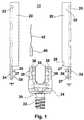
- FIG. 1is a side plan view of the retractor device, with parts separated, in accordance with the present disclosure
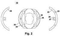
- FIG. 2is a top view of the retractor device of FIG. 1 ;
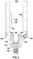
- FIG. 3is a side plan view of an alternative slot configuration of a retractor device in accordance with another embodiment of the present disclosure
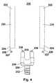
- FIG. 4is a side plan view of a retractor device with a horizontal hinge configuration in accordance with a further embodiment of the present disclosure
- FIG. 5is a top view of the retractor device of FIG. 4 ;
- FIG. 6is a front cross-sectional view of a vertebral body with a pair of minimally invasive retractors attached using screws with the blades in their initial position and rods positioned in the passages of the minimally invasive retractors.
- the retractor device of the present disclosureis used to conduct minimally invasive spine surgery.
- a retracting bladeis removeably attached to a pedicle bone screw which is used to guide the retractor into place and act as a point of fixation with respect to the patient.
- a retracting blade, pedicle bone screw, and systems and methods for useare disclosed in U.S. patent application Ser. No. 11/528,223 filed Sep. 26, 2006 (U.S. Patent Application Publication No. 2007/0106123), the entire contents of which are hereby incorporated by reference herein.
- proximalwill refer to the end of a device or system that is closest to the operator, while the term “distal” will refer to the end of the device or system that is farthest from the operator.
- FIGS. 1 and 2illustrate a side plan view and a top view of the retractor device in accordance with the principles of the present disclosure.
- Retractor device 10includes retracting blades 20 and pedicle screw 30 .
- Pedicle screw 30may be a monoaxial screw or may be a polyaxial screw, as shown.
- Retracting blades 20are discussed singularly as they are substantially identical.
- Retracting blade 20includes proximal end 22 and distal end 24 , and defines a longitudinal axis “t” extending along the length of the blade.
- the cross-section of retracting blade 20is generally a circular ring sector which provides stiffness to the retracting blade so that it will not yield to the counter force of the retracted tissue.
- the arcuate or concave shape of retracting blade 20is adapted and configured for positioning about pedicle screw 30 as well as for guiding insertion of other instruments.
- Distal end 24 of retracting blade 20includes at least one projection 26 .
- Two projections 26are illustrated in the current embodiment, each projection 26 being a substantially flat surface traverse to longitudinal axis “t”.
- Each projection 26includes passage 27 which is arranged coincident with longitudinal axis “t”. Passage 27 may be circular, oval, oblong, square, rectangular, or other shape as known in the art.
- Retracting blade 20may include one or more living hinges 28 along proximal or distal ends 22 , 24 so that retracting blade 20 may flex.
- the geometryis configured so that retracting blade 20 bends at living hinge(s) 28 and still is able to retract tissue against which it is pressed.
- More than one living hinge 28may be incorporated to aid in bending along any portion of the blade's length. It is also contemplated that true hinges may be used in lieu of the disclosed living hinges 28 .
- Retracting blade 20may also have one or more transverse through holes 29 disposed on the retractor at points along axis “t”.
- standard surgical instrumentssuch as a Gelpi retractor
- use of two or more retracting bladesalso forms an internal channel whereby other surgical instruments may be placed such that retracting blades 20 provide an open area with good visibility of the screw head to aid in the insertion of instruments and implants.
- Retracting blade 20may be a single monolithically formed unit or composed of several components connected to each other through conventional means, such as, for example, ultrasonic welding, or any other means known in the art.
- Retracting blade 20may be formed of any suitable medical grade material, including metals such as stainless steel, titanium, nickel-titanium, aluminum, or alloys thereof, or rigid or semi-rigid materials, including polymeric materials such as polyetheretherketones, polycarbonate, polypropylene, and polyethylene; and composites thereof.
- Retracting blade 20may have a reflective or non-reflective coating, as appropriate to aid in increasing visibility in the wound or may have an artificial lighting feature.
- Retracting blade 20may have a light emitting surface containing a light source such as a self-contained LED light engine or channel 23 for a fiber optic cable carrying light from a remote source.
- Retracting blade 20may include any number of channels 23 . Further, the light emitting surface may be mounted on, integrally formed with, or faceted on retracting blade 20 .
- Pedicle screw 30includes threaded shaft 32 and movable head 34 .
- Movable head 34may be rotatable and/or have polyaxial rotation which allows for free angular movement with respect to threaded body 32 .
- Movable head 34includes retaining portion 35 .
- Retaining portion 35has channel 38 .
- retaining portion 35is contiguously raised from the top of movable head 34 and also contains two slots 36 .
- Pedicle screwsare known in the art and include structure for securing a rod therein.
- Known securing structuresinclude a taper lock and a set screw. Examples of such pedicle screws are disclosed in U.S. Pat. No. 5,683,392 to Richelsoph et al., U.S. Pat. No. 5,733,286 to Errico et al., U.S. Pat. No. 5,443,467 to Biedermann et al., U.S. Pat. No. 6,565,565 to Yuan et al., and published U.S. Patent Application 2007/0093817 to Barrus.
- Pedicle screw 30may be formed of any suitable medical grade material, particularly titanium.
- Movable headmay be monolithically formed or composed of several components connected to each other through conventional means as described above.
- the pedicle screwmay be cannulated such that it may be translated along a guide wire, thereby facilitating insertion of the pedicle screw and the retractor device into the work site.
- conventional insertion toolsor those disclosed in U.S. patent application Ser. No. 12/104,653, filed on Apr. 17, 2008 (U.S. Patent Application Publication No. 2008/0262318), the entire contents of which are hereby incorporated by reference, may be used in conjunction with the presently disclosed retractor devices and pedicle screws.
- Retracting blade 20 and pedicle screw 30are joined by inserting projection 26 of retracting blade 20 into slot 36 of pedicle screw 30 .
- two projections 26are inserted into two slots 36 .
- Passage 27 of retracting blade 20is then aligned with channel 38 of pedicle screw 30 so that retracting blade 20 and pedicle screw 30 are releasably coupled by retention pin 40 .
- Retention pin 40is used to join retracting blade 20 and pedicle screw 30 .
- Retention pin 40has the same or similar geometry as passage 27 of retracting blade 20 and channel 38 of screw 30 so that it may be placed therein when passage 27 is aligned with channel 38 .
- retracting blade 20will move with movable head 34 , as well as flex for tissue retraction.
- retention pin 40may have a tether 42 , such as wire cable, for ease of removal from a remote location outside the patient.
- Retractor device 10may be constructed as shown, or in reverse so that retaining portions are on retracting blade and projections are in the pedicle screw. Further, the number, length, angle, and size of projection(s) 26 of retracting blade 20 may vary and accordingly, retaining portion 35 of pedicle screw 30 will correspond to the size, number, and configuration of projection(s) 26 so that the retracting blade 20 and pedicle screw 30 may be joined together.
- FIG. 3illustrates another embodiment of the presently described retractor device shown generally as 110 .
- Retractor device 110includes retracting blade 120 and pedicle screw 130 .
- Pedicle screw 130has threaded shaft 132 and movable head 134 having retaining portion 135 .
- retracting blade 120has one projection 126 that is angled.
- Retaining portion 135 of pedicle screw 130has angled slot 136 .
- Retracting blade 120 and pedicle screw 130are joined by inserting angled projection 126 of the retracting blade 120 into angled slot 136 of pedicle screw 130 . Passage 127 of retracting blade 120 is then aligned with channel 138 of pedicle screw 130 so that retracting blade 120 and pedicle screw 130 are releasably coupled by retention pin 140 .
- Retention pin 140has the same or similar geometry as passage 127 of retracting blade 120 and channel 138 of screw 130 so that is my be placed longitudinally therein when passage 127 is aligned with channel 138 to join retracting blade 120 and pedicle screw 130 . Once joined, retracting blade 120 will move with movable head 134 , as well as flex thereabout with separating therefrom.
- retention pin 140may have a tether 142 , such as a wire cable, for ease of removal from a remote location outside the patient.
- Retractor device 210includes retracting blades 220 and pedicle screw 230 .
- Retracting blades 220each have proximal and distal ends 222 , 224 .
- Distal end 224has projection 226 and slot or channel 227 .
- Pedicle screw 230has threaded shaft 232 and movable head 234 .
- Movable head 234includes at least one retaining portion 235 which has a channel 238 .
- pedicle screw 230has two retaining portions 235 and channels 238 . Retaining portions 235 and slots 238 are joined by inserting projection 226 of retracting blade 220 between retaining portions 235 of pedicle screw 230 and securing them with retention pin 240 . Retention pin 240 is transversely placed through the passage 227 of retracting blade 220 and channel 238 of pedicle screw 230 for hingedly connecting retracting blade 220 to pedicle screw 230 so that retracting blade 220 can move with movable head 234 and/or proximally thereto.
- retracting bladesmay be used in conjunction with a single pedicle screw to allow retraction in multiple directions and multiple retracting blades may be used with multiple screws, respectively, during a single spine procedure.
- the retractor devicemay be manufactured for a single use or can be sterilized and reused.
- Retractor device 10is assembled with pedicle screw 30 as shown in FIG. 6 .
- the assembled apparatusis inserted into an incision through the patient's skin S and muscle/fat tissue T such that pedicle screw 30 is subsequently threaded into a vertebral body V.
- retracting blades 20are spread and/or pivoted apart to retract skin S and tissue T to create a retracted area at the target site.
- a rod 3is inserted in a passage 18 when passage 18 is in an expanded state (i.e., tissue has been retracted).
- the rodmay be inserted along a path from one screw head to another, possibly subcutaneously such that it may be secured to fastening regions of pedicle screws in adjacent vertebral bodies.
- the retractor devices of the present disclosureare well suited for such a technique due to the unique access provided.
- the physicianmay remove retention pin 40 proximally from channel 38 using tether 42 or an elongated tool and separate retracting blades 20 from pedicle screw 30 , thereby allowing proximal movement of the retracting blades 20 .
- the retracting blades 20 of the retractor device 10are separated from pedicle screw 30 without imparting significant downward or rotational forces against the patient's body. Retracting blades 20 may then be removed from the patient and this process may be repeated for each installed retractor device 10 .
- retractorsmust have the ability to be sterilized using known materials and techniques.
- Partsmay be sterile packed by the manufacturer or sterilized on site by the user. Sterile packed parts may be individually packed or packed in any desirable quantity.
- a sterile packagemay contain one or a plurality of retractors in a sterile enclosure.
- such a sterile surgical kitmay also include one or a plurality of bone biopsy needles(s), Jamshidi needle(s), guide wires, sterile cannulated scalpels, dilators, rods, or other surgical instruments.
- the bladesmay be made of a light transmitting material.
- the retractormay include a light guide system.
- the light guide systemhas an input adapter to receive light from a light source and one or more light emitting surfaces to illuminate the surgical field.
- the retaining portionmay be removably attached to the pedicle screw.
- the retaining portioncould include frangible sections attached to the pedicle screw or otherwise have engagement structure for removably engaging the screw.
- the retractor bladescould be permanently affixed to the removable retaining portion or may be separable from the removable retaining portion. In either case, the blades may be separated from the retaining portion or the retaining portion may be separated from the screw by twisting (to disengage an engagement such as a thread or bayonet mount), or by breaking off frangible sections when retraction is no longer required.
- the retaining portioncould mount to internal or external threads on upstanding portions of the pedicle screw. Such threads could be the same threads on the screw for engaging a nut or set screw to secure a rod seated in the screw.
- the retractors and methods described hereinmay find use in other orthopedic surgery applications, such as trauma surgery.
- the dilator, scalpel and retractors (or some of them) of the present disclosuremay be used, with or without a bone screw.
Landscapes
- Health & Medical Sciences (AREA)
- Orthopedic Medicine & Surgery (AREA)
- Surgery (AREA)
- Life Sciences & Earth Sciences (AREA)
- Neurology (AREA)
- Molecular Biology (AREA)
- Heart & Thoracic Surgery (AREA)
- Medical Informatics (AREA)
- Biomedical Technology (AREA)
- Animal Behavior & Ethology (AREA)
- General Health & Medical Sciences (AREA)
- Public Health (AREA)
- Veterinary Medicine (AREA)
- Engineering & Computer Science (AREA)
- Nuclear Medicine, Radiotherapy & Molecular Imaging (AREA)
- Surgical Instruments (AREA)
Abstract
Description
Claims (19)
Priority Applications (2)
| Application Number | Priority Date | Filing Date | Title |
|---|---|---|---|
| US12/396,188US8097026B2 (en) | 2008-02-28 | 2009-03-02 | Minimally invasive retraction device having removable blades |
| US13/333,496US8414625B2 (en) | 2008-02-28 | 2011-12-21 | Minimally invasive retraction device having removable blades |
Applications Claiming Priority (2)
| Application Number | Priority Date | Filing Date | Title |
|---|---|---|---|
| US3213508P | 2008-02-28 | 2008-02-28 | |
| US12/396,188US8097026B2 (en) | 2008-02-28 | 2009-03-02 | Minimally invasive retraction device having removable blades |
Related Child Applications (1)
| Application Number | Title | Priority Date | Filing Date |
|---|---|---|---|
| US13/333,496ContinuationUS8414625B2 (en) | 2008-02-28 | 2011-12-21 | Minimally invasive retraction device having removable blades |
Publications (2)
| Publication Number | Publication Date |
|---|---|
| US20090222046A1 US20090222046A1 (en) | 2009-09-03 |
| US8097026B2true US8097026B2 (en) | 2012-01-17 |
Family
ID=41013745
Family Applications (2)
| Application Number | Title | Priority Date | Filing Date |
|---|---|---|---|
| US12/396,188Expired - Fee RelatedUS8097026B2 (en) | 2008-02-28 | 2009-03-02 | Minimally invasive retraction device having removable blades |
| US13/333,496Expired - Fee RelatedUS8414625B2 (en) | 2008-02-28 | 2011-12-21 | Minimally invasive retraction device having removable blades |
Family Applications After (1)
| Application Number | Title | Priority Date | Filing Date |
|---|---|---|---|
| US13/333,496Expired - Fee RelatedUS8414625B2 (en) | 2008-02-28 | 2011-12-21 | Minimally invasive retraction device having removable blades |
Country Status (1)
| Country | Link |
|---|---|
| US (2) | US8097026B2 (en) |
Cited By (15)
| Publication number | Priority date | Publication date | Assignee | Title |
|---|---|---|---|---|
| US20100174325A1 (en)* | 2008-10-17 | 2010-07-08 | Omni Surgical L.P. dba Spine 360 | Poly-axial pedicle screw assembly |
| US20110093015A1 (en)* | 2009-10-20 | 2011-04-21 | Ramsay Christopher L | Spinal implant with a flexible extension element |
| US20120116460A1 (en)* | 2008-02-28 | 2012-05-10 | K2M, Inc. | Minimally invasive retraction device having removable blades |
| US20130053896A1 (en)* | 2011-08-29 | 2013-02-28 | Jean-Marc VOYADZIS | Adaptable systems, methods, and devices for percutaneously implanting a spinal screw |
| US20160310174A1 (en)* | 2010-04-23 | 2016-10-27 | DePuy Synthes Products, Inc. | Minimally invasive instrument set, devices, and related methods |
| US9795370B2 (en) | 2014-08-13 | 2017-10-24 | Nuvasive, Inc. | Minimally disruptive retractor and associated methods for spinal surgery |
| US9907578B2 (en)* | 2008-09-05 | 2018-03-06 | Biedermann Technologies Gmbh & Co. Kg | Bone anchoring element and stabilization device for bones, in particular for the spinal column |
| US20190090918A1 (en)* | 2004-02-27 | 2019-03-28 | Roger P. Jackson | Tool system for dynamic spinal implants |
| USD846119S1 (en) | 2017-01-24 | 2019-04-16 | Medtronic Advanced Energy Llc | Lighted surgical retractor base |
| US10441325B2 (en) | 2006-04-11 | 2019-10-15 | DePuy Synthes Products, Inc. | Minimally invasive fixation system |
| US10736618B2 (en) | 2017-01-24 | 2020-08-11 | Medtronic Advanced Energy Llc | Modular lighted surgical retractor |
| US10993739B2 (en) | 2009-05-20 | 2021-05-04 | DePuy Synthes Products, Inc. | Patient-mounted retraction |
| US20210220023A1 (en)* | 2020-01-21 | 2021-07-22 | Warsaw Orthopedic, Inc. | Multi-cap removing-and-holding instrument for spinal surgeries |
| US11622795B2 (en)* | 2015-10-27 | 2023-04-11 | Ctl Medical Corporation | Modular rod reduction tower and related methods |
| US12440248B2 (en)* | 2022-06-28 | 2025-10-14 | DePuy Synthes Products, Inc. | Minimally invasive instrument set, devices, and related methods |
Families Citing this family (55)
| Publication number | Priority date | Publication date | Assignee | Title |
|---|---|---|---|---|
| WO2006058221A2 (en) | 2004-11-24 | 2006-06-01 | Abdou Samy M | Devices and methods for inter-vertebral orthopedic device placement |
| US8696560B2 (en) | 2006-05-02 | 2014-04-15 | K2M, Inc. | Minimally open retraction device |
| US20090222044A1 (en)* | 2008-02-28 | 2009-09-03 | K2M, Inc. | Minimally Invasive Retractor Screw and Methods of Use |
| US8747407B2 (en)* | 2008-02-28 | 2014-06-10 | K2M, Inc. | Minimally invasive retractor and methods of use |
| US8246538B2 (en)* | 2008-02-28 | 2012-08-21 | K2M, Inc. | Minimally invasive retractor with separable blades and methods of use |
| US20090221879A1 (en)* | 2008-02-28 | 2009-09-03 | K2M, Inc. | Minimally Invasive Retractor Having Separable Blades |
| US8932210B2 (en)* | 2008-02-28 | 2015-01-13 | K2M, Inc. | Minimally invasive retraction device having detachable blades |
| CA2739431C (en)* | 2008-10-01 | 2016-12-06 | Sherwin Hua | System and method for wire-guided pedicle screw stabilization of spinal vertebrae |
| WO2011123580A1 (en) | 2010-03-30 | 2011-10-06 | Sherwin Hua | Systems and methods for pedicle screw stabilization of spinal vertebrae |
| WO2011022787A1 (en)* | 2009-08-31 | 2011-03-03 | Kevin Seex | Retractor blade including a flexible member for anchorage engagement |
| US9078701B2 (en)* | 2009-11-09 | 2015-07-14 | Centinel Spine, Inc. | System and method for stabilizing a posterior fusion over motion segments |
| DE112010004338B4 (en) | 2009-11-10 | 2019-06-27 | Nuvasive, Inc. | DEVICE FOR IMPLEMENTING SPINE SURGERY |
| US8764806B2 (en) | 2009-12-07 | 2014-07-01 | Samy Abdou | Devices and methods for minimally invasive spinal stabilization and instrumentation |
| US8545505B2 (en)* | 2010-01-15 | 2013-10-01 | Pioneer Surgical Technology, Inc. | Low friction rod persuader |
| US8636655B1 (en) | 2010-01-19 | 2014-01-28 | Ronald Childs | Tissue retraction system and related methods |
| WO2011119690A1 (en) | 2010-03-26 | 2011-09-29 | Echostar Technologies L.L.C. | Multiple input television receiver |
| US9113960B2 (en)* | 2010-06-08 | 2015-08-25 | Globus Medical, Inc. | Conforming bone stabilization receiver |
| US20120109304A1 (en)* | 2010-10-29 | 2012-05-03 | Warsaw Orthopedic, Inc. | Medical implant and method for photodynamic therapy |
| US8956284B2 (en)* | 2011-01-20 | 2015-02-17 | K2M, Inc. | Minimally invasive retractor and posted screw |
| US9307972B2 (en) | 2011-05-10 | 2016-04-12 | Nuvasive, Inc. | Method and apparatus for performing spinal fusion surgery |
| US8617218B2 (en) | 2011-05-13 | 2013-12-31 | Warsaw Orthoepdic, Inc. | Bone anchor extenders |
| US8845728B1 (en) | 2011-09-23 | 2014-09-30 | Samy Abdou | Spinal fixation devices and methods of use |
| US20130226240A1 (en) | 2012-02-22 | 2013-08-29 | Samy Abdou | Spinous process fixation devices and methods of use |
| US9220539B2 (en) | 2012-03-19 | 2015-12-29 | Warsaw Orthopedic, Inc. | Spinal implant system and method |
| US9078709B2 (en) | 2012-03-19 | 2015-07-14 | Warsaw Orthopedic, Inc. | Spinal implant system and method |
| US8439924B1 (en) | 2012-04-02 | 2013-05-14 | Warsaw Orthopedic, Inc. | Spinal implant system and method |
| US9451998B2 (en) | 2012-08-17 | 2016-09-27 | Warsaw Orthopedic, Inc. | Spinal implant system and method |
| US9066758B2 (en) | 2012-08-17 | 2015-06-30 | Warsaw Orthopedic, Inc. | Spinal implant system and method |
| US9198767B2 (en) | 2012-08-28 | 2015-12-01 | Samy Abdou | Devices and methods for spinal stabilization and instrumentation |
| US9320617B2 (en) | 2012-10-22 | 2016-04-26 | Cogent Spine, LLC | Devices and methods for spinal stabilization and instrumentation |
| US9084591B2 (en) | 2012-10-23 | 2015-07-21 | Neurostructures, Inc. | Retractor |
| US9370383B2 (en) | 2013-03-15 | 2016-06-21 | Zimmer Biomet Spine, Inc. | Minimally invasive splitable pedicle screw extender |
| US9402659B2 (en) | 2013-08-06 | 2016-08-02 | Warsaw Orthopedic, Inc. | Spinal implant system |
| US9848863B2 (en) | 2015-02-25 | 2017-12-26 | Globus Medical, Inc | Surgical retractor systems and methods |
| EP3106110B1 (en)* | 2015-06-16 | 2017-10-11 | Biedermann Technologies GmbH & Co. KG | Extension device for a bone anchor |
| US10149674B2 (en) | 2015-08-12 | 2018-12-11 | K2M, Inc. | Orthopedic surgical system including surgical access systems, distraction systems, and methods of using same |
| US10499894B2 (en) | 2015-08-12 | 2019-12-10 | K2M, Inc. | Orthopedic surgical system including surgical access systems, distraction systems, and methods of using same |
| US9700293B2 (en) | 2015-08-18 | 2017-07-11 | Globus Medical, Inc. | Devices and systems for surgical retraction |
| US10857003B1 (en) | 2015-10-14 | 2020-12-08 | Samy Abdou | Devices and methods for vertebral stabilization |
| WO2018035309A1 (en)* | 2016-08-17 | 2018-02-22 | University Of Maryland, Baltimore | Corpectomy device and methods of use thereof |
| US11109894B2 (en) | 2016-09-26 | 2021-09-07 | Dr. Bryan Barnes Pc | Apparatus, system, and method for spinal vertebrae stabilization |
| US10973648B1 (en) | 2016-10-25 | 2021-04-13 | Samy Abdou | Devices and methods for vertebral bone realignment |
| US10744000B1 (en) | 2016-10-25 | 2020-08-18 | Samy Abdou | Devices and methods for vertebral bone realignment |
| DE102017114273A1 (en)* | 2017-06-27 | 2018-12-27 | Silony Medical International AG | Extension device for a bone anchor |
| US10863975B2 (en) | 2017-07-14 | 2020-12-15 | Carefusion 2200, Inc. | Adjustable length, reusable retraction blades |
| US10736667B2 (en)* | 2017-10-06 | 2020-08-11 | Warsaw Orthopedic, Inc. | Spinal implant system and methods of use |
| US10736666B2 (en)* | 2017-10-06 | 2020-08-11 | Warsaw Orthopedic, Inc | Spinal implant system and methods of use |
| US11179248B2 (en) | 2018-10-02 | 2021-11-23 | Samy Abdou | Devices and methods for spinal implantation |
| US11484350B2 (en) | 2018-12-13 | 2022-11-01 | Zimmer Biomet Spine, Inc. | Split tower for a bone anchor |
| US11559337B2 (en) | 2018-12-14 | 2023-01-24 | Zimmer Biomet Spine, Inc. | Expended tab reinforcement sleeve |
| US11160580B2 (en) | 2019-04-24 | 2021-11-02 | Spine23 Inc. | Systems and methods for pedicle screw stabilization of spinal vertebrae |
| EP4065016A1 (en) | 2019-11-27 | 2022-10-05 | Spine23 Inc. | Systems, devices and methods for treating a lateral curvature of a spine |
| US11786277B2 (en)* | 2020-08-12 | 2023-10-17 | Snj Patents, Llc | Tower pedicle screw system |
| WO2022094434A1 (en) | 2020-10-30 | 2022-05-05 | Anderson M D Christian | Dynamic ligament repair device |
| WO2022241140A1 (en) | 2021-05-12 | 2022-11-17 | Spine23 Inc. | Systems and methods for pedicle screw stabilization of spinal vertebrae |
Citations (61)
| Publication number | Priority date | Publication date | Assignee | Title |
|---|---|---|---|---|
| US3129706A (en) | 1962-11-13 | 1964-04-21 | Jr Walker Reynolds | Surgical retractor |
| US3486505A (en) | 1967-05-22 | 1969-12-30 | Gordon M Morrison | Orthopedic surgical instrument |
| US5242443A (en) | 1991-08-15 | 1993-09-07 | Smith & Nephew Dyonics, Inc. | Percutaneous fixation of vertebrae |
| US5431658A (en) | 1994-02-14 | 1995-07-11 | Moskovich; Ronald | Facilitator for vertebrae grafts and prostheses |
| US5496321A (en) | 1993-11-19 | 1996-03-05 | Cross Medical Products, Inc. | Rod anchor seat having a sliding interlocking rod connector |
| US5545165A (en) | 1992-10-09 | 1996-08-13 | Biedermann Motech Gmbh | Anchoring member |
| US5582577A (en) | 1995-02-13 | 1996-12-10 | Vance Products Incorporated | Surgical retractor including central elastic member |
| US5685826A (en) | 1990-11-05 | 1997-11-11 | General Surgical Innovations, Inc. | Mechanically expandable arthroscopic retractors and method of using the same |
| US5797911A (en) | 1996-09-24 | 1998-08-25 | Sdgi Holdings, Inc. | Multi-axial bone screw assembly |
| US5902231A (en) | 1996-03-22 | 1999-05-11 | Sdgi Holdings, Inc. | Devices and methods for percutaneous surgery |
| US5944658A (en) | 1997-09-23 | 1999-08-31 | Koros; Tibor B. | Lumbar spinal fusion retractor and distractor system |
| US6063088A (en) | 1997-03-24 | 2000-05-16 | United States Surgical Corporation | Method and instrumentation for implant insertion |
| US6083225A (en) | 1996-03-14 | 2000-07-04 | Surgical Dynamics, Inc. | Method and instrumentation for implant insertion |
| US6099547A (en) | 1997-02-13 | 2000-08-08 | Scimed Life Systems, Inc. | Method and apparatus for minimally invasive pelvic surgery |
| US6102951A (en) | 1997-06-12 | 2000-08-15 | Sulzer Orthopaedie Ag | Mounting system for metallic support shells |
| US6146385A (en) | 1997-02-11 | 2000-11-14 | Smith & Nephew, Inc. | Repairing cartilage |
| US6187000B1 (en) | 1998-08-20 | 2001-02-13 | Endius Incorporated | Cannula for receiving surgical instruments |
| US6200322B1 (en) | 1999-08-13 | 2001-03-13 | Sdgi Holdings, Inc. | Minimal exposure posterior spinal interbody instrumentation and technique |
| US6206826B1 (en) | 1997-12-18 | 2001-03-27 | Sdgi Holdings, Inc. | Devices and methods for percutaneous surgery |
| US6270501B1 (en) | 1999-11-08 | 2001-08-07 | The Regents Of The University Of Michigan | Surgical method and apparatus and cannulated scalpel for use therein |
| US6280442B1 (en) | 1999-09-01 | 2001-08-28 | Sdgi Holdings, Inc. | Multi-axial bone screw assembly |
| US6360750B1 (en) | 1999-04-29 | 2002-03-26 | Medtronic, Inc. | Minimally invasive surgical techniques for implanting devices that deliver stimulant to the nervous system |
| US6478800B1 (en) | 2000-05-08 | 2002-11-12 | Depuy Acromed, Inc. | Medical installation tool |
| US6485494B1 (en) | 1996-12-20 | 2002-11-26 | Thomas T. Haider | Pedicle screw system for osteosynthesis |
| US20030004401A1 (en) | 2001-06-29 | 2003-01-02 | Robert Ball | Self retaining retractor ring |
| US6530926B1 (en) | 2000-08-01 | 2003-03-11 | Endius Incorporated | Method of securing vertebrae |
| US6530929B1 (en) | 1999-10-20 | 2003-03-11 | Sdgi Holdings, Inc. | Instruments for stabilization of bony structures |
| US6616605B2 (en) | 2001-02-15 | 2003-09-09 | Genesee Biomedical, Inc. | Quadretractor and method of use |
| US20030191371A1 (en) | 2002-04-05 | 2003-10-09 | Smith Maurice M. | Devices and methods for percutaneous tissue retraction and surgery |
| US6652533B2 (en) | 2001-09-20 | 2003-11-25 | Depuy Acromed, Inc. | Medical inserter tool with slaphammer |
| US6669729B2 (en) | 2002-03-08 | 2003-12-30 | Kingsley Richard Chin | Apparatus and method for the replacement of posterior vertebral elements |
| US6740091B2 (en) | 1997-03-06 | 2004-05-25 | Sulzer Spine-Tech Inc. | Lordotic spinal implant |
| US6743206B1 (en) | 2000-03-07 | 2004-06-01 | Syntheon, Llc | Endoscopic needle |
| US20040138662A1 (en) | 2002-10-30 | 2004-07-15 | Landry Michael E. | Spinal stabilization systems and methods |
| US6796422B1 (en) | 2003-08-07 | 2004-09-28 | Bae Her Industrial Corp. | Eyeglass case |
| US6849064B2 (en) | 2002-10-25 | 2005-02-01 | James S. Hamada | Minimal access lumbar diskectomy instrumentation and method |
| US20050065517A1 (en) | 2003-09-24 | 2005-03-24 | Chin Kingsley Richard | Methods and devices for improving percutaneous access in minimally invasive surgeries |
| US20050131408A1 (en) | 2003-12-16 | 2005-06-16 | Sicvol Christopher W. | Percutaneous access devices and bone anchor assemblies |
| US20050131421A1 (en) | 2003-12-16 | 2005-06-16 | Anderson David G. | Methods and devices for minimally invasive spinal fixation element placement |
| US20050165408A1 (en) | 2004-01-26 | 2005-07-28 | Puno Rolando M. | Methods and instrumentation for inserting intervertebral grafts and devices |
| US6929606B2 (en) | 2001-01-29 | 2005-08-16 | Depuy Spine, Inc. | Retractor and method for spinal pedicle screw placement |
| US20050215999A1 (en) | 2004-03-19 | 2005-09-29 | Depuy Spine, Inc. | Spinal fixation element and methods |
| US20060074445A1 (en) | 2004-09-29 | 2006-04-06 | David Gerber | Less invasive surgical system and methods |
| US7056321B2 (en) | 2000-08-01 | 2006-06-06 | Endius, Incorporated | Method of securing vertebrae |
| US7083621B2 (en) | 2003-04-25 | 2006-08-01 | Sdgi Holdings, Inc. | Articulating spinal fixation rod and system |
| US20060264962A1 (en) | 2003-09-24 | 2006-11-23 | Chin Kingsley R | System and method for spinal implant placement |
| US7144393B2 (en) | 2001-05-15 | 2006-12-05 | Dipoto Gene P | Structure for receiving surgical instruments |
| US7160300B2 (en) | 2004-02-27 | 2007-01-09 | Jackson Roger P | Orthopedic implant rod reduction tool set and method |
| US7166107B2 (en) | 2000-09-11 | 2007-01-23 | D. Greg Anderson | Percutaneous technique and implant for expanding the spinal canal |
| US20070049931A1 (en) | 2005-08-26 | 2007-03-01 | Sdgi Holdings, Inc. | Instruments for minimally invasive stabilization of bony structures |
| US20070055247A1 (en) | 2003-09-24 | 2007-03-08 | N Spine, Inc. | Marking and guidance method and system for flexible fixation of a spine |
| US20070106123A1 (en) | 2005-09-26 | 2007-05-10 | Josef Gorek | Minimally invasive retractor and methods of use |
| WO2007084641A2 (en) | 2006-01-18 | 2007-07-26 | Spotlight Surgical, Inc. | Retractor illumination system |
| US20080114403A1 (en) | 2006-11-09 | 2008-05-15 | Zimmer Spine, Inc. | Minimally invasive pedicle screw access system and associated method |
| US20080119849A1 (en) | 2006-11-20 | 2008-05-22 | Depuy Spine Inc. | Break-off screw extensions |
| US7491208B2 (en) | 2005-04-28 | 2009-02-17 | Warsaw Orthopedic, Inc. | Instrument and method for guiding surgical implants and instruments during surgery |
| US20090131755A1 (en)* | 2007-10-08 | 2009-05-21 | Patrick Michel White | Retractor for minimally invasive surgery |
| US20090221877A1 (en) | 2008-02-28 | 2009-09-03 | K2M, Inc. | Minimally Invasive Retraction Device Having Detachable Blades |
| US20090222045A1 (en) | 2008-02-28 | 2009-09-03 | K2M, Inc. | Minimally Invasive Retractor and Methods of Use |
| US20090221879A1 (en) | 2008-02-28 | 2009-09-03 | K2M, Inc. | Minimally Invasive Retractor Having Separable Blades |
| US20090222044A1 (en) | 2008-02-28 | 2009-09-03 | K2M, Inc. | Minimally Invasive Retractor Screw and Methods of Use |
Family Cites Families (1)
| Publication number | Priority date | Publication date | Assignee | Title |
|---|---|---|---|---|
| US8097026B2 (en)* | 2008-02-28 | 2012-01-17 | K2M, Inc. | Minimally invasive retraction device having removable blades |
- 2009
- 2009-03-02USUS12/396,188patent/US8097026B2/ennot_activeExpired - Fee Related
- 2011
- 2011-12-21USUS13/333,496patent/US8414625B2/ennot_activeExpired - Fee Related
Patent Citations (76)
| Publication number | Priority date | Publication date | Assignee | Title |
|---|---|---|---|---|
| US3129706A (en) | 1962-11-13 | 1964-04-21 | Jr Walker Reynolds | Surgical retractor |
| US3486505A (en) | 1967-05-22 | 1969-12-30 | Gordon M Morrison | Orthopedic surgical instrument |
| US5685826A (en) | 1990-11-05 | 1997-11-11 | General Surgical Innovations, Inc. | Mechanically expandable arthroscopic retractors and method of using the same |
| US5242443A (en) | 1991-08-15 | 1993-09-07 | Smith & Nephew Dyonics, Inc. | Percutaneous fixation of vertebrae |
| US5545165A (en) | 1992-10-09 | 1996-08-13 | Biedermann Motech Gmbh | Anchoring member |
| US5496321A (en) | 1993-11-19 | 1996-03-05 | Cross Medical Products, Inc. | Rod anchor seat having a sliding interlocking rod connector |
| US5431658A (en) | 1994-02-14 | 1995-07-11 | Moskovich; Ronald | Facilitator for vertebrae grafts and prostheses |
| US5582577A (en) | 1995-02-13 | 1996-12-10 | Vance Products Incorporated | Surgical retractor including central elastic member |
| US6083225A (en) | 1996-03-14 | 2000-07-04 | Surgical Dynamics, Inc. | Method and instrumentation for implant insertion |
| US5902231A (en) | 1996-03-22 | 1999-05-11 | Sdgi Holdings, Inc. | Devices and methods for percutaneous surgery |
| US5797911A (en) | 1996-09-24 | 1998-08-25 | Sdgi Holdings, Inc. | Multi-axial bone screw assembly |
| US6485494B1 (en) | 1996-12-20 | 2002-11-26 | Thomas T. Haider | Pedicle screw system for osteosynthesis |
| US6358253B1 (en) | 1997-02-11 | 2002-03-19 | Smith & Newhew Inc | Repairing cartilage |
| US6146385A (en) | 1997-02-11 | 2000-11-14 | Smith & Nephew, Inc. | Repairing cartilage |
| US6099547A (en) | 1997-02-13 | 2000-08-08 | Scimed Life Systems, Inc. | Method and apparatus for minimally invasive pelvic surgery |
| US6740091B2 (en) | 1997-03-06 | 2004-05-25 | Sulzer Spine-Tech Inc. | Lordotic spinal implant |
| US6063088A (en) | 1997-03-24 | 2000-05-16 | United States Surgical Corporation | Method and instrumentation for implant insertion |
| US6102951A (en) | 1997-06-12 | 2000-08-15 | Sulzer Orthopaedie Ag | Mounting system for metallic support shells |
| US5944658A (en) | 1997-09-23 | 1999-08-31 | Koros; Tibor B. | Lumbar spinal fusion retractor and distractor system |
| US6206826B1 (en) | 1997-12-18 | 2001-03-27 | Sdgi Holdings, Inc. | Devices and methods for percutaneous surgery |
| US6800084B2 (en) | 1998-08-20 | 2004-10-05 | Endius Incorporated | Method for performing a surgical procedure and a cannula for use in performing the surgical procedure |
| US7108705B2 (en) | 1998-08-20 | 2006-09-19 | Endius, Inc. | Cannula for receiving surgical instruments |
| US6187000B1 (en) | 1998-08-20 | 2001-02-13 | Endius Incorporated | Cannula for receiving surgical instruments |
| US6360750B1 (en) | 1999-04-29 | 2002-03-26 | Medtronic, Inc. | Minimally invasive surgical techniques for implanting devices that deliver stimulant to the nervous system |
| US6200322B1 (en) | 1999-08-13 | 2001-03-13 | Sdgi Holdings, Inc. | Minimal exposure posterior spinal interbody instrumentation and technique |
| US6280442B1 (en) | 1999-09-01 | 2001-08-28 | Sdgi Holdings, Inc. | Multi-axial bone screw assembly |
| US7188626B2 (en) | 1999-10-20 | 2007-03-13 | Warsaw Orthopedic, Inc. | Instruments and methods for stabilization of bony structures |
| US7011660B2 (en) | 1999-10-20 | 2006-03-14 | Sdgi Holdings, Inc. | Instruments and methods for stabilization of bony structures |
| US6530929B1 (en) | 1999-10-20 | 2003-03-11 | Sdgi Holdings, Inc. | Instruments for stabilization of bony structures |
| US7008422B2 (en) | 1999-10-20 | 2006-03-07 | Sdgi Holdings, Inc. | Instruments and methods for stabilization of bony structures |
| US20060200135A1 (en) | 1999-10-20 | 2006-09-07 | Sherman Michael C | Instruments and methods for stabilization of bony structures |
| US20060229614A1 (en) | 1999-10-20 | 2006-10-12 | Foley Kevin T | Instruments and methods for stabilization of bony structures |
| US6270501B1 (en) | 1999-11-08 | 2001-08-07 | The Regents Of The University Of Michigan | Surgical method and apparatus and cannulated scalpel for use therein |
| US6743206B1 (en) | 2000-03-07 | 2004-06-01 | Syntheon, Llc | Endoscopic needle |
| US6755841B2 (en) | 2000-05-08 | 2004-06-29 | Depuy Acromed, Inc. | Medical installation tool |
| US6478800B1 (en) | 2000-05-08 | 2002-11-12 | Depuy Acromed, Inc. | Medical installation tool |
| US7056321B2 (en) | 2000-08-01 | 2006-06-06 | Endius, Incorporated | Method of securing vertebrae |
| US6530926B1 (en) | 2000-08-01 | 2003-03-11 | Endius Incorporated | Method of securing vertebrae |
| US7166107B2 (en) | 2000-09-11 | 2007-01-23 | D. Greg Anderson | Percutaneous technique and implant for expanding the spinal canal |
| US6929606B2 (en) | 2001-01-29 | 2005-08-16 | Depuy Spine, Inc. | Retractor and method for spinal pedicle screw placement |
| US6616605B2 (en) | 2001-02-15 | 2003-09-09 | Genesee Biomedical, Inc. | Quadretractor and method of use |
| US7144393B2 (en) | 2001-05-15 | 2006-12-05 | Dipoto Gene P | Structure for receiving surgical instruments |
| US20030004401A1 (en) | 2001-06-29 | 2003-01-02 | Robert Ball | Self retaining retractor ring |
| US6652533B2 (en) | 2001-09-20 | 2003-11-25 | Depuy Acromed, Inc. | Medical inserter tool with slaphammer |
| US6669729B2 (en) | 2002-03-08 | 2003-12-30 | Kingsley Richard Chin | Apparatus and method for the replacement of posterior vertebral elements |
| US20030191371A1 (en) | 2002-04-05 | 2003-10-09 | Smith Maurice M. | Devices and methods for percutaneous tissue retraction and surgery |
| US6849064B2 (en) | 2002-10-25 | 2005-02-01 | James S. Hamada | Minimal access lumbar diskectomy instrumentation and method |
| US7250052B2 (en) | 2002-10-30 | 2007-07-31 | Abbott Spine Inc. | Spinal stabilization systems and methods |
| US20040138662A1 (en) | 2002-10-30 | 2004-07-15 | Landry Michael E. | Spinal stabilization systems and methods |
| US20040143265A1 (en) | 2002-10-30 | 2004-07-22 | Landry Michael E. | Spinal stabilization systems and methods using minimally invasive surgical procedures |
| US7083621B2 (en) | 2003-04-25 | 2006-08-01 | Sdgi Holdings, Inc. | Articulating spinal fixation rod and system |
| US6796422B1 (en) | 2003-08-07 | 2004-09-28 | Bae Her Industrial Corp. | Eyeglass case |
| US20060264962A1 (en) | 2003-09-24 | 2006-11-23 | Chin Kingsley R | System and method for spinal implant placement |
| US20070055247A1 (en) | 2003-09-24 | 2007-03-08 | N Spine, Inc. | Marking and guidance method and system for flexible fixation of a spine |
| US20050065517A1 (en) | 2003-09-24 | 2005-03-24 | Chin Kingsley Richard | Methods and devices for improving percutaneous access in minimally invasive surgeries |
| US20070129731A1 (en) | 2003-12-16 | 2007-06-07 | Christopher Sicvol | Percutaneous Access Devices And Bone Anchor Assemblies |
| US20050131408A1 (en) | 2003-12-16 | 2005-06-16 | Sicvol Christopher W. | Percutaneous access devices and bone anchor assemblies |
| US7179261B2 (en) | 2003-12-16 | 2007-02-20 | Depuy Spine, Inc. | Percutaneous access devices and bone anchor assemblies |
| US20050131421A1 (en) | 2003-12-16 | 2005-06-16 | Anderson David G. | Methods and devices for minimally invasive spinal fixation element placement |
| US20070167954A1 (en) | 2003-12-16 | 2007-07-19 | Christopher Sicvol | Percutaneous Access Devices And Bone Anchor Assemblies |
| US20050154389A1 (en) | 2003-12-16 | 2005-07-14 | Depuy Spine, Inc. | Methods and devices for minimally invasive spinal fixation element placement |
| US20050165408A1 (en) | 2004-01-26 | 2005-07-28 | Puno Rolando M. | Methods and instrumentation for inserting intervertebral grafts and devices |
| US7160300B2 (en) | 2004-02-27 | 2007-01-09 | Jackson Roger P | Orthopedic implant rod reduction tool set and method |
| US20050215999A1 (en) | 2004-03-19 | 2005-09-29 | Depuy Spine, Inc. | Spinal fixation element and methods |
| US20060074445A1 (en) | 2004-09-29 | 2006-04-06 | David Gerber | Less invasive surgical system and methods |
| US7491208B2 (en) | 2005-04-28 | 2009-02-17 | Warsaw Orthopedic, Inc. | Instrument and method for guiding surgical implants and instruments during surgery |
| US20070049931A1 (en) | 2005-08-26 | 2007-03-01 | Sdgi Holdings, Inc. | Instruments for minimally invasive stabilization of bony structures |
| US20070106123A1 (en) | 2005-09-26 | 2007-05-10 | Josef Gorek | Minimally invasive retractor and methods of use |
| WO2007084641A2 (en) | 2006-01-18 | 2007-07-26 | Spotlight Surgical, Inc. | Retractor illumination system |
| US20080114403A1 (en) | 2006-11-09 | 2008-05-15 | Zimmer Spine, Inc. | Minimally invasive pedicle screw access system and associated method |
| US20080119849A1 (en) | 2006-11-20 | 2008-05-22 | Depuy Spine Inc. | Break-off screw extensions |
| US20090131755A1 (en)* | 2007-10-08 | 2009-05-21 | Patrick Michel White | Retractor for minimally invasive surgery |
| US20090221877A1 (en) | 2008-02-28 | 2009-09-03 | K2M, Inc. | Minimally Invasive Retraction Device Having Detachable Blades |
| US20090222045A1 (en) | 2008-02-28 | 2009-09-03 | K2M, Inc. | Minimally Invasive Retractor and Methods of Use |
| US20090221879A1 (en) | 2008-02-28 | 2009-09-03 | K2M, Inc. | Minimally Invasive Retractor Having Separable Blades |
| US20090222044A1 (en) | 2008-02-28 | 2009-09-03 | K2M, Inc. | Minimally Invasive Retractor Screw and Methods of Use |
Non-Patent Citations (1)
| Title |
|---|
| U.S. Appl. No. 12/941,143, filed Nov. 8, 2010. |
Cited By (31)
| Publication number | Priority date | Publication date | Assignee | Title |
|---|---|---|---|---|
| US20190090918A1 (en)* | 2004-02-27 | 2019-03-28 | Roger P. Jackson | Tool system for dynamic spinal implants |
| US11058465B2 (en)* | 2004-02-27 | 2021-07-13 | Nuvasive, Inc. | Tool system for dynamic spinal implants |
| US10441325B2 (en) | 2006-04-11 | 2019-10-15 | DePuy Synthes Products, Inc. | Minimally invasive fixation system |
| US20120116460A1 (en)* | 2008-02-28 | 2012-05-10 | K2M, Inc. | Minimally invasive retraction device having removable blades |
| US8414625B2 (en)* | 2008-02-28 | 2013-04-09 | K2M, Inc. | Minimally invasive retraction device having removable blades |
| US9907578B2 (en)* | 2008-09-05 | 2018-03-06 | Biedermann Technologies Gmbh & Co. Kg | Bone anchoring element and stabilization device for bones, in particular for the spinal column |
| US20100174325A1 (en)* | 2008-10-17 | 2010-07-08 | Omni Surgical L.P. dba Spine 360 | Poly-axial pedicle screw assembly |
| US8439923B2 (en)* | 2008-10-17 | 2013-05-14 | Omni Surgical LLC | Poly-axial pedicle screw assembly |
| US12349936B2 (en) | 2009-05-20 | 2025-07-08 | DePuy Synthes Products, Inc. | Patient-mounted retraction |
| US10993739B2 (en) | 2009-05-20 | 2021-05-04 | DePuy Synthes Products, Inc. | Patient-mounted retraction |
| US9855077B2 (en) | 2009-10-20 | 2018-01-02 | DePuy Synthes Products, Inc. | Spinal implant with a flexible extension element |
| US9364265B2 (en) | 2009-10-20 | 2016-06-14 | DePuy Synthes Products, Inc. | Spinal implant with a flexible extension element |
| US8236032B2 (en) | 2009-10-20 | 2012-08-07 | Depuy Spine, Inc. | Spinal implant with a flexible extension element |
| US20110093015A1 (en)* | 2009-10-20 | 2011-04-21 | Ramsay Christopher L | Spinal implant with a flexible extension element |
| US10888360B2 (en)* | 2010-04-23 | 2021-01-12 | DePuy Synthes Products, Inc. | Minimally invasive instrument set, devices, and related methods |
| US20160310174A1 (en)* | 2010-04-23 | 2016-10-27 | DePuy Synthes Products, Inc. | Minimally invasive instrument set, devices, and related methods |
| US11389213B2 (en) | 2010-04-23 | 2022-07-19 | DePuy Synthes Products, Inc. | Minimally invasive instrument set, devices, and related methods |
| US20220323122A1 (en)* | 2010-04-23 | 2022-10-13 | DePuy Synthes Products, Inc. | Minimally invasive instrument set, devices, and related methods |
| US20130053896A1 (en)* | 2011-08-29 | 2013-02-28 | Jean-Marc VOYADZIS | Adaptable systems, methods, and devices for percutaneously implanting a spinal screw |
| US9962147B2 (en) | 2014-08-13 | 2018-05-08 | Nuvasive, Inc. | Minimally disruptive retractor and associated methods for spinal surgery |
| US10660628B2 (en) | 2014-08-13 | 2020-05-26 | Nuvasive, Inc. | Minimally disruptive retractor and associated methods for spinal surgery |
| US9795370B2 (en) | 2014-08-13 | 2017-10-24 | Nuvasive, Inc. | Minimally disruptive retractor and associated methods for spinal surgery |
| US12108947B2 (en) | 2014-08-13 | 2024-10-08 | Nuvasive, Inc. | Minimally disruptive retractor and associated methods for spinal surgery |
| US11399816B2 (en) | 2014-08-13 | 2022-08-02 | Nuvasive, Inc. | Minimally disruptive retractor and associated methods for spinal surgery |
| US20230240728A1 (en)* | 2015-10-27 | 2023-08-03 | Ctl Medical Corporation | Modular rod reduction tower and related methods |
| US11622795B2 (en)* | 2015-10-27 | 2023-04-11 | Ctl Medical Corporation | Modular rod reduction tower and related methods |
| USD846119S1 (en) | 2017-01-24 | 2019-04-16 | Medtronic Advanced Energy Llc | Lighted surgical retractor base |
| US11717279B2 (en) | 2017-01-24 | 2023-08-08 | Medtronic Advanced Energy Llc | Modular lighted surgical retractor |
| US10736618B2 (en) | 2017-01-24 | 2020-08-11 | Medtronic Advanced Energy Llc | Modular lighted surgical retractor |
| US20210220023A1 (en)* | 2020-01-21 | 2021-07-22 | Warsaw Orthopedic, Inc. | Multi-cap removing-and-holding instrument for spinal surgeries |
| US12440248B2 (en)* | 2022-06-28 | 2025-10-14 | DePuy Synthes Products, Inc. | Minimally invasive instrument set, devices, and related methods |
Also Published As
| Publication number | Publication date |
|---|---|
| US20090222046A1 (en) | 2009-09-03 |
| US20120116460A1 (en) | 2012-05-10 |
| US8414625B2 (en) | 2013-04-09 |
Similar Documents
| Publication | Publication Date | Title |
|---|---|---|
| US8097026B2 (en) | Minimally invasive retraction device having removable blades | |
| US8932210B2 (en) | Minimally invasive retraction device having detachable blades | |
| US8246538B2 (en) | Minimally invasive retractor with separable blades and methods of use | |
| US11812940B2 (en) | Minimally open interbody access retraction device and surgical method | |
| US9510858B2 (en) | Minimally invasive retractor and methods of use | |
| US8747407B2 (en) | Minimally invasive retractor and methods of use | |
| US11389213B2 (en) | Minimally invasive instrument set, devices, and related methods | |
| US20090221879A1 (en) | Minimally Invasive Retractor Having Separable Blades | |
| US20140243602A1 (en) | Minimally invasive retractor screw and methods of use | |
| US8956284B2 (en) | Minimally invasive retractor and posted screw | |
| AU2013263733B2 (en) | Minimally invasive retractor and methods of use |
Legal Events
| Date | Code | Title | Description |
|---|---|---|---|
| AS | Assignment | Owner name:K2M, INC., VIRGINIA Free format text:ASSIGNMENT OF ASSIGNORS INTEREST;ASSIGNOR:GOREK, JOSEF;REEL/FRAME:022481/0433 Effective date:20090324 | |
| AS | Assignment | Owner name:SILICON VALLEY BANK, CALIFORNIA Free format text:ADDENDUM TO INTELLECTUAL PROPERTY SECURITY AGREEMENT;ASSIGNOR:K2M, INC.;REEL/FRAME:026565/0482 Effective date:20110629 | |
| ZAAA | Notice of allowance and fees due | Free format text:ORIGINAL CODE: NOA | |
| ZAAB | Notice of allowance mailed | Free format text:ORIGINAL CODE: MN/=. | |
| ZAAA | Notice of allowance and fees due | Free format text:ORIGINAL CODE: NOA | |
| ZAAB | Notice of allowance mailed | Free format text:ORIGINAL CODE: MN/=. | |
| STCF | Information on status: patent grant | Free format text:PATENTED CASE | |
| AS | Assignment | Owner name:SILICON VALLEY BANK, MASSACHUSETTS Free format text:SECURITY INTEREST;ASSIGNORS:K2M, INC.;K2M HOLDING, INC.;K2M UK LIMITED;REEL/FRAME:029489/0327 Effective date:20121029 | |
| AS | Assignment | Owner name:K2M, INC., VIRGINIA Free format text:TERMINATION;ASSIGNOR:SILICON VALLEY BANK;REEL/FRAME:030918/0426 Effective date:20121029 | |
| AS | Assignment | Owner name:SILICON VALLEY BANK, CALIFORNIA Free format text:FIRST AMENDMENT TO PATENT SECURITY AGREEMENT;ASSIGNORS:K2M, INC.;K2M UNLIMITED;K2M HOLDINGS, INC.;REEL/FRAME:034034/0097 Effective date:20141021 | |
| FPAY | Fee payment | Year of fee payment:4 | |
| AS | Assignment | Owner name:K2M UK LIMITED, UNITED KINGDOM Free format text:RELEASE BY SECURED PARTY;ASSIGNOR:SILICON VALLEY BANK;REEL/FRAME:047496/0001 Effective date:20181109 Owner name:K2M HOLDINGS, INC., VIRGINIA Free format text:RELEASE BY SECURED PARTY;ASSIGNOR:SILICON VALLEY BANK;REEL/FRAME:047496/0001 Effective date:20181109 Owner name:K2M, INC., VIRGINIA Free format text:RELEASE BY SECURED PARTY;ASSIGNOR:SILICON VALLEY BANK;REEL/FRAME:047496/0001 Effective date:20181109 | |
| FEPP | Fee payment procedure | Free format text:ENTITY STATUS SET TO UNDISCOUNTED (ORIGINAL EVENT CODE: BIG.); ENTITY STATUS OF PATENT OWNER: LARGE ENTITY | |
| MAFP | Maintenance fee payment | Free format text:PAYMENT OF MAINTENANCE FEE, 8TH YEAR, LARGE ENTITY (ORIGINAL EVENT CODE: M1552); ENTITY STATUS OF PATENT OWNER: LARGE ENTITY Year of fee payment:8 | |
| FEPP | Fee payment procedure | Free format text:MAINTENANCE FEE REMINDER MAILED (ORIGINAL EVENT CODE: REM.); ENTITY STATUS OF PATENT OWNER: LARGE ENTITY | |
| LAPS | Lapse for failure to pay maintenance fees | Free format text:PATENT EXPIRED FOR FAILURE TO PAY MAINTENANCE FEES (ORIGINAL EVENT CODE: EXP.); ENTITY STATUS OF PATENT OWNER: LARGE ENTITY | |
| STCH | Information on status: patent discontinuation | Free format text:PATENT EXPIRED DUE TO NONPAYMENT OF MAINTENANCE FEES UNDER 37 CFR 1.362 | |
| FP | Lapsed due to failure to pay maintenance fee | Effective date:20240117 |