US8096994B2 - Percutaneous spinal implants and methods - Google Patents
Percutaneous spinal implants and methodsDownload PDFInfo
- Publication number
- US8096994B2 US8096994B2US11/693,496US69349607AUS8096994B2US 8096994 B2US8096994 B2US 8096994B2US 69349607 AUS69349607 AUS 69349607AUS 8096994 B2US8096994 B2US 8096994B2
- Authority
- US
- United States
- Prior art keywords
- implant
- spinal implant
- elongate member
- configuration
- distal end
- Prior art date
- Legal status (The legal status is an assumption and is not a legal conclusion. Google has not performed a legal analysis and makes no representation as to the accuracy of the status listed.)
- Active, expires
Links
- 239000007943implantSubstances0.000titleclaimsabstractdescription544
- 238000000034methodMethods0.000titleclaimsdescription164
- 230000008569processEffects0.000claimsdescription113
- 230000000717retained effectEffects0.000claimsdescription2
- 230000014759maintenance of locationEffects0.000description34
- 238000003780insertionMethods0.000description26
- 230000037431insertionEffects0.000description26
- 239000000463materialSubstances0.000description17
- 230000008878couplingEffects0.000description16
- 238000010168coupling processMethods0.000description16
- 238000005859coupling reactionMethods0.000description16
- 125000006850spacer groupChemical group0.000description15
- 210000001519tissueAnatomy0.000description11
- 208000005198spinal stenosisDiseases0.000description7
- 210000000988bone and boneAnatomy0.000description6
- 210000000278spinal cordAnatomy0.000description6
- 230000001154acute effectEffects0.000description5
- RTAQQCXQSZGOHL-UHFFFAOYSA-NTitaniumChemical compound[Ti]RTAQQCXQSZGOHL-UHFFFAOYSA-N0.000description4
- 239000000853adhesiveSubstances0.000description4
- 230000001070adhesive effectEffects0.000description4
- 230000006835compressionEffects0.000description4
- 238000007906compressionMethods0.000description4
- 230000006870functionEffects0.000description4
- 230000013011matingEffects0.000description4
- 239000010936titaniumSubstances0.000description4
- 229910052719titaniumInorganic materials0.000description4
- 230000036407painEffects0.000description3
- 238000001356surgical procedureMethods0.000description3
- 230000007704transitionEffects0.000description3
- 239000004696Poly ether ether ketoneSubstances0.000description2
- 238000013459approachMethods0.000description2
- 238000005452bendingMethods0.000description2
- 230000008859changeEffects0.000description2
- 238000010276constructionMethods0.000description2
- 230000000694effectsEffects0.000description2
- -1for exampleSubstances0.000description2
- 210000003041ligamentAnatomy0.000description2
- 229920002530polyetherether ketonePolymers0.000description2
- 239000007787solidSubstances0.000description2
- 229910001220stainless steelInorganic materials0.000description2
- 239000010935stainless steelSubstances0.000description2
- BSYNRYMUTXBXSQ-UHFFFAOYSA-NAspirinChemical compoundCC(=O)OC1=CC=CC=C1C(O)=OBSYNRYMUTXBXSQ-UHFFFAOYSA-N0.000description1
- 206010006784Burning sensationDiseases0.000description1
- 229920000049Carbon (fiber)Polymers0.000description1
- 206010029174Nerve compressionDiseases0.000description1
- 206010033799ParalysisDiseases0.000description1
- 239000004698PolyethyleneSubstances0.000description1
- 208000007103SpondylolisthesisDiseases0.000description1
- 229960001138acetylsalicylic acidDrugs0.000description1
- 230000008901benefitEffects0.000description1
- 239000000560biocompatible materialSubstances0.000description1
- 239000008280bloodSubstances0.000description1
- 210000004369bloodAnatomy0.000description1
- 210000001217buttockAnatomy0.000description1
- 244000309466calfSpecies0.000description1
- 239000004917carbon fiberSubstances0.000description1
- 238000004891communicationMethods0.000description1
- 239000003246corticosteroidSubstances0.000description1
- 230000006837decompressionEffects0.000description1
- 230000000991decompressive effectEffects0.000description1
- 238000002695general anesthesiaMethods0.000description1
- 238000002513implantationMethods0.000description1
- 239000007924injectionSubstances0.000description1
- 238000002347injectionMethods0.000description1
- 230000003871intestinal functionEffects0.000description1
- 238000002684laminectomyMethods0.000description1
- 210000002414legAnatomy0.000description1
- 230000007246mechanismEffects0.000description1
- 229910001092metal group alloyInorganic materials0.000description1
- VNWKTOKETHGBQD-UHFFFAOYSA-NmethaneChemical compoundCVNWKTOKETHGBQD-UHFFFAOYSA-N0.000description1
- 238000002324minimally invasive surgeryMethods0.000description1
- 238000012986modificationMethods0.000description1
- 230000004048modificationEffects0.000description1
- 229940021182non-steroidal anti-inflammatory drugDrugs0.000description1
- 231100000862numbnessToxicity0.000description1
- 238000000554physical therapyMethods0.000description1
- 239000004033plasticSubstances0.000description1
- 229920003023plasticPolymers0.000description1
- 229920000573polyethylenePolymers0.000description1
- 208000037821progressive diseaseDiseases0.000description1
- 230000000750progressive effectEffects0.000description1
- 210000001032spinal nerveAnatomy0.000description1
- 210000000273spinal nerve rootAnatomy0.000description1
- 150000003431steroidsChemical class0.000description1
- 229910000811surgical stainless steelInorganic materials0.000description1
- 239000012207thread-locking agentSubstances0.000description1
- 238000013519translationMethods0.000description1
- 238000003466weldingMethods0.000description1
Images


Classifications
- A—HUMAN NECESSITIES
- A61—MEDICAL OR VETERINARY SCIENCE; HYGIENE
- A61B—DIAGNOSIS; SURGERY; IDENTIFICATION
- A61B17/00—Surgical instruments, devices or methods
- A61B17/56—Surgical instruments or methods for treatment of bones or joints; Devices specially adapted therefor
- A61B17/58—Surgical instruments or methods for treatment of bones or joints; Devices specially adapted therefor for osteosynthesis, e.g. bone plates, screws or setting implements
- A61B17/68—Internal fixation devices, including fasteners and spinal fixators, even if a part thereof projects from the skin
- A61B17/70—Spinal positioners or stabilisers, e.g. stabilisers comprising fluid filler in an implant
- A61B17/7062—Devices acting on, attached to, or simulating the effect of, vertebral processes, vertebral facets or ribs ; Tools for such devices
- A61B17/7065—Devices with changeable shape, e.g. collapsible or having retractable arms to aid implantation; Tools therefor
- A—HUMAN NECESSITIES
- A61—MEDICAL OR VETERINARY SCIENCE; HYGIENE
- A61B—DIAGNOSIS; SURGERY; IDENTIFICATION
- A61B17/00—Surgical instruments, devices or methods
- A61B17/56—Surgical instruments or methods for treatment of bones or joints; Devices specially adapted therefor
- A61B17/58—Surgical instruments or methods for treatment of bones or joints; Devices specially adapted therefor for osteosynthesis, e.g. bone plates, screws or setting implements
- A61B17/68—Internal fixation devices, including fasteners and spinal fixators, even if a part thereof projects from the skin
- A61B17/70—Spinal positioners or stabilisers, e.g. stabilisers comprising fluid filler in an implant
- A—HUMAN NECESSITIES
- A61—MEDICAL OR VETERINARY SCIENCE; HYGIENE
- A61F—FILTERS IMPLANTABLE INTO BLOOD VESSELS; PROSTHESES; DEVICES PROVIDING PATENCY TO, OR PREVENTING COLLAPSING OF, TUBULAR STRUCTURES OF THE BODY, e.g. STENTS; ORTHOPAEDIC, NURSING OR CONTRACEPTIVE DEVICES; FOMENTATION; TREATMENT OR PROTECTION OF EYES OR EARS; BANDAGES, DRESSINGS OR ABSORBENT PADS; FIRST-AID KITS
- A61F2/00—Filters implantable into blood vessels; Prostheses, i.e. artificial substitutes or replacements for parts of the body; Appliances for connecting them with the body; Devices providing patency to, or preventing collapsing of, tubular structures of the body, e.g. stents
- A61F2/02—Prostheses implantable into the body
- A61F2/30—Joints
- A61F2/44—Joints for the spine, e.g. vertebrae, spinal discs
- A—HUMAN NECESSITIES
- A61—MEDICAL OR VETERINARY SCIENCE; HYGIENE
- A61B—DIAGNOSIS; SURGERY; IDENTIFICATION
- A61B17/00—Surgical instruments, devices or methods
- A61B2017/00535—Surgical instruments, devices or methods pneumatically or hydraulically operated
- A61B2017/00557—Surgical instruments, devices or methods pneumatically or hydraulically operated inflatable
Definitions
- the inventionrelates generally to the treatment of spinal conditions, and more particularly, to the treatment of spinal compression using percutaneous spinal implants for implantation between adjacent spinous processes.
- spinal stenosisis a progressive narrowing of the spinal canal that causes compression of the spinal cord.
- Each vertebra in the spinal columnhas an opening that extends through it. The openings are aligned vertically to form the spinal canal.
- the spinal cordruns through the spinal canal. As the spinal canal narrows, the spinal cord and nerve roots extending from the spinal cord and between adjacent vertebrae are compressed and may become inflamed.
- Spinal stenosiscan cause pain, weakness, numbness, burning sensations, tingling, and in particularly severe cases, may cause loss of bladder or bowel function, or paralysis.
- the legs, calves and buttocksare most commonly affected by spinal stenosis, however, the shoulders and arms may also be affected.
- Mild cases of spinal stenosismay be treated with rest or restricted activity, non-steroidal anti-inflammatory drugs (e.g., aspirin), corticosteroid injections (epidural steroids), and/or physical therapy.
- non-steroidal anti-inflammatory drugse.g., aspirin
- corticosteroid injectionsepidural steroids
- physical therapye.g., physical therapy.
- Some patientsfind that bending forward, sitting or lying down may help relieve the pain. This may be due to bending forward creates more vertebral space, which may temporarily relieve nerve compression.
- spinal stenosisis a progressive disease, the source of pressure may have to be surgically corrected (decompressive laminectomy) as the patient has increasing pain. The surgical procedure can remove bone and other tissues that have impinged upon the spinal canal or put pressure on the spinal cord.
- Two adjacent vertebraemay also be fused during the surgical procedure to prevent an area of instability, improper alignment or slippage, such as that caused by spondylolisthesis.
- Surgical decompressioncan relieve pressure on the spinal cord or spinal nerve by widening the spinal canal to create more space.
- This procedurerequires that the patient be given a general anesthesia as an incision is made in the patient to access the spine to remove the areas that are contributing to the pressure. This procedure, however, may result in blood loss and an increased chance of significant complications, and usually results in an extended hospital stay.
- Minimally-invasive procedureshave been developed to provide access to the space between adjacent spinous processes such that major surgery is not required. Such known procedures, however, may not be suitable in conditions where the spinous processes are severely compressed. Moreover, such procedures typically involve large or multiple incisions.
- an apparatusincludes an elongate member configured to engage a spinal implant and a locking member.
- the locking memberis disposed at a distal end portion of the elongate member.
- the locking memberis configured to move relative to the elongate member between a first position and a second position in a direction substantially perpendicular to a center line of the elongate member.
- the locking memberis configured to allow the distal end portion of the elongate member to move relative to the spinal implant when in the first position.
- the locking memberis configured to couple the distal end portion of the elongate member to the spinal implant when in the second position.
- FIG. 1is a schematic illustration of a posterior view of a medical device according to an embodiment of the invention in a first configuration adjacent two adjacent spinous processes.
- FIG. 2is a schematic illustration of a posterior view of a medical device according to an embodiment of the invention in a second configuration adjacent two adjacent spinous processes.
- FIG. 3is a schematic illustration of a deforming element according to an embodiment of the invention in a first configuration.
- FIG. 4is a schematic illustration of a side view of the expanding element illustrated in FIG. 3 .
- FIG. 5is a side view of a medical device according to an embodiment of the invention in a first configuration.
- FIG. 6is a side view of the medical device illustrated in FIG. 5 in a second configuration.
- FIG. 7is a perspective view of a medical device according to an embodiment of the invention in a first configuration.
- FIG. 8is a posterior view of a medical device according to an embodiment of the invention, a portion of which is in a second configuration.
- FIG. 9is a posterior view of the medical device illustrated in FIG. 7 fully deployed in the second configuration.
- FIG. 10is a front plan view of the medical device illustrated in FIG. 7 in the second configuration.
- FIG. 11is a perspective view of an implant expansion device according to an embodiment of the invention.
- FIG. 12is an alternative perspective view of the implant expansion device illustrated in FIG. 11 .
- FIG. 13is a perspective view of a portion of the implant expansion device illustrated in FIG. 11 .
- FIG. 14is a cross-sectional view of a portion of the device illustrated in FIG. 11 , taken along line A-A in FIG. 11 .
- FIG. 15is a cross-sectional view of a portion of the device illustrated in FIG. 11 in a first configuration, taken along line B-B in FIG. 11 .
- FIG. 16is a cross-sectional view of a portion of the device illustrated in FIG. 11 in a second configuration, taken along line C-C in FIG. 11 .
- FIG. 17is a side perspective view of an implant according to an embodiment of the invention shown in a collapsed configuration.
- FIG. 18is a cross-sectional view of the implant of FIG. 17 taken along line 18 - 18 .
- FIG. 19is a side perspective view of the implant of FIG. 17 shown in an expanded configuration.
- FIG. 20is a rear perspective view of the implant of FIG. 17 shown in a collapsed configuration.
- FIG. 21is cross-sectional view of the implant of FIG. 17 shown in a collapsed configuration taken along line 21 - 21 .
- FIG. 22is a rear perspective view of an implant according to an embodiment of the invention shown in a collapsed configuration.
- FIG. 23is a cross-sectional view of the implant of FIG. 22 shown in a collapsed configuration.
- FIG. 24is a perspective view of the implant of FIG. 22 in a collapsed configuration disposed on an expansion tool according to an embodiment of the invention.
- FIG. 25is a perspective view of the implant and the expansion tool of FIG. 24 taken along region 25 .
- FIG. 26is a side cross-sectional view of the implant and the expansion tool of FIG. 24 .
- FIG. 27is a side cross-sectional view of the implant and the expansion tool as shown in FIG. 26 taken along region 27 .
- FIG. 28is a perspective view of the implant of FIG. 22 in an expanded configuration disposed on an expansion tool according to an embodiment of the invention.
- FIG. 29is a perspective view of the implant and the expansion tool of FIG. 28 taken along region 29 .
- FIG. 30is a side cross-sectional view of the implant and the expansion tool of FIG. 28 .
- FIG. 31is a side cross-sectional view of the implant and the expansion tool as shown in FIG. 30 taken along region 31 .
- FIG. 32is a schematic illustration of a medical device according to an embodiment of the invention in a collapsed configuration adjacent two spinous processes.
- FIG. 33is a schematic illustration of the medical device of FIG. 32 in an expanded configuration adjacent two spinous processes.
- FIG. 34is a side view of a portion of a medical device including an engaging portion in an extended configuration, according to an embodiment of the invention, positioned adjacent a spinous process.
- FIG. 35is a side view of the portion of the medical device of FIG. 34 including the engaging portion in a partially collapsed configuration.
- FIG. 36is a side view of the portion of the medical device of FIG. 34 including the engaging portion in the extended configuration after being inserted past the spinous process.
- FIG. 37is a side perspective view of an implant according to an embodiment of the invention in an expanded configuration.
- FIG. 38is a side perspective view of the implant of FIG. 37 shown in a collapsed configuration.
- FIG. 39is a side perspective view of the medical device of FIG. 37 shown in a collapsed configuration.
- FIG. 40is a side view of a deployment tool according to an embodiment of the invention.
- FIG. 41is a side view of a portion of the deployment tool of FIG. 40 shown in a first configuration.
- FIG. 42is a side view of the portion of the deployment tool of FIG. 41 shown in a second configuration.
- FIG. 43is a side view of a portion of the deployment tool of FIG. 41 and the implant of FIG. 37 with the implant shown in an expanded configuration.
- FIG. 44is a cross-sectional view of the portion of the deployment tool and implant shown in FIG. 43 .
- FIG. 45is a cross-sectional view of the deployment tool and implant of FIG. 43 with the implant shown in a collapsed configuration positioned between adjacent spinous processes.
- FIG. 46is a side perspective view of the implant of FIG. 37 shown rotated about a longitudinal axis of the implant.
- FIG. 47is a side perspective view of an implant according to another embodiment of the invention.
- FIG. 48is a side view of a deployment tool according to another embodiment of the invention.
- FIG. 49is a side view of a deployment tool according to another embodiment of the invention.
- FIG. 50is a side view of a deployment tool according to another embodiment of the invention.
- FIG. 51is a side view of a deployment tool according to another embodiment of the invention.
- FIGS. 52 and 53are schematic illustrations of a deployment tool according to an embodiment of the invention, in a first configuration and a second configuration, respectively.
- FIG. 54is a perspective view of a deployment tool according to an embodiment of the invention.
- FIG. 55is a perspective view of a spinal implant according to an embodiment of the invention.
- FIG. 56is a perspective cross-sectional view of a portion of the deployment tool shown in FIG. 54 .
- FIG. 57is a perspective view of a portion of the deployment tool shown in FIG. 54 .
- FIG. 58is a perspective view of a portion of the deployment tool shown in FIG. 54 .
- FIG. 59is a perspective view of a portion of the deployment tool shown in FIG. 54 .
- FIG. 60is a perspective view of a portion of the deployment tool shown in FIG. 54 .
- FIG. 61is a front cross-sectional view of a portion of the deployment tool shown in FIG. 54 in a first configuration.
- FIG. 62is a front cross-sectional view of a portion of the deployment tool shown in FIG. 54 in a second configuration.
- FIGS. 63 and 64are schematic illustrations of a deployment tool according to an embodiment of the invention, in a first configuration and a second configuration, respectively.
- FIGS. 65 and 66are schematic illustrations of a deployment tool according to an embodiment of the invention, in a first configuration and a second configuration, respectively.
- FIG. 67is a perspective view of a deployment tool according to an embodiment of the invention.
- FIG. 68is a front cross-sectional view of a spinal implant according to an embodiment of the invention.
- FIG. 69is a perspective view of a portion of the deployment tool shown as region 69 in FIG. 67 .
- FIG. 70is a front cross-sectional view of the portion of the deployment tool shown in FIG. 69 taken along line 70 - 70 in FIG. 69 .
- FIGS. 71-73are a front cross-sectional views of the portion of the deployment tool shown in FIG. 69 and the spinal implant shown in FIG. 68 in a first configuration, a second configuration and a third configuration, respectively.
- FIG. 74is a schematic illustration of a deployment tool according to an embodiment of the invention.
- FIG. 75is a front view of a deployment tool according to an embodiment of the invention.
- FIG. 76is a side view of the deployment tool shown in FIG. 75 .
- FIGS. 77 and 80are a front view of the deployment tool shown in FIG. 75 in a first configuration and a second configuration, respectively.
- FIGS. 78 and 79are side views of the deployment tool shown in FIG. 75 in a first configuration and a second configuration, respectively.
- FIG. 81is a front view of the deployment tool shown in FIG. 75 in a third configuration.
- FIGS. 82 and 83are schematic illustrations of a medical device according to an embodiment of the invention, in a first configuration and a second configuration, respectively.
- FIG. 84is a top view schematic illustration of the medical device shown in FIG. 83 , in the second configuration.
- FIGS. 85-87are cross-sectional front views of a medical device according to an embodiment of the invention, in a first configuration, a second configuration and a third configuration, respectively.
- FIG. 88is a schematic illustration of a medical device according to an embodiment of the invention.
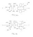
- FIG. 89is a flow chart of a method according to an embodiment of the invention.
- FIG. 90is a flow chart of a method according to an embodiment of the invention.
- FIG. 91is a flow chart of a method according to an embodiment of the invention.
- FIG. 92is a flow chart of a method according to an embodiment of the invention.
- proximal and distalrefer to direction closer to and away from, respectively, an operator (e.g., surgeon, physician, nurse, technician, etc.) who would insert the medical device into the patient, with the tip-end (i.e., distal end) of the device inserted inside a patient's body first.
- an operatore.g., surgeon, physician, nurse, technician, etc.
- the tip-endi.e., distal end of the device inserted inside a patient's body first.
- the implant end first inserted inside the patient's bodywould be the distal end of the implant, while the implant end to last enter the patient's body would be the proximal end of the implant.
- an apparatusin some embodiments, includes an elongate member configured to engage a spinal implant and a locking member.
- the locking memberis disposed at a distal end portion of the elongate member.
- the locking memberis configured to move relative to the elongate member between a first position and a second position in a direction substantially perpendicular to a center line of the elongate member.
- the locking memberis configured to allow the distal end portion of the elongate member to move relative to the spinal implant when in the first position.
- the locking memberis configured to couple the distal end portion of the elongate member to the spinal implant when in the second position.
- an apparatusin some embodiments, includes an elongate member configured to engage a spinal implant, a sleeve and a locking member.
- the locking memberis disposed at a distal end portion of the elongate member.
- the locking memberis configured to move relative to the elongate member between a first position and a second position in a direction substantially perpendicular to a center line of the elongate member.
- the locking memberis configured to allow the distal end portion of the elongate member to move relative to the spinal implant when in the first position.
- the locking memberis configured complimentarily fit with an opening defined by the spinal implant to couple the distal end portion of the elongate member to the spinal implant when in the second position.
- the sleeveis disposed about an outer surface of the elongate member and is configured to retain the locking member within the opening when the sleeve is in a first position.
- an apparatusin some embodiments, includes a first elongate member configured to engage a spinal implant, a second elongate member movably disposed within the first elongate member, and a locking member.
- the locking memberis disposed at a distal end portion of the elongate member.
- the locking memberis configured to move relative to the first elongate member between a first position and a second position in a direction substantially perpendicular to a center line of the first elongate member.
- the locking memberis configured to allow the distal end portion of the first elongate member to move relative to the spinal implant when in the first position.
- the locking memberis configured to couple the distal end portion of the first elongate member to the spinal implant when in the second position.
- the second elongate memberis configured to move an inner member of the spinal implant relative to a portion of an outer member of the spinal implant when the locking member is in the second position.
- an apparatusin some embodiments, includes an elongate member and a locking member.
- the elongate memberhas a distal end portion configured to be removably disposed within an interior portion of a spinal implant.
- the locking memberis configured to releasably couple the distal end portion of the elongate member to the spinal implant.
- the locking memberwhich can be, for example, a ball, a pin and/or a retaining ring, is configured to be disposed substantially within the interior portion of the spinal implant such that the elongate member moves relative to the spinal implant when the locking member is in a first configuration.
- the locking memberis configured to engage a surface defining the interior portion of the spinal implant such that the elongate member cannot substantially move relative to the spinal implant when the locking member is in a second configuration.
- an apparatusin some embodiments, includes an elongate member configured to engage a spinal implant, a locking member and an actuator.
- the locking memberis disposed at a distal end portion of the elongate member and has a first configuration and a second configuration.
- the locking memberis configured to allow the distal end portion of the elongate member to move relative to the spinal implant when in the first configuration.
- the locking memberis configured to couple the distal end portion of the elongate member to the spinal implant when in the second configuration.
- the actuatoris disposed at the distal end portion of the elongate member and is configured to move the locking member from its first configuration to its second configuration when the elongate member engages the spinal implant.
- the actuatorcan be any suitable actuator, such as for example, a mechanical actuator (e.g., a spring-loaded actuator), a pneumatic actuator, a hydraulic actuator and/or an electronic actuator.
- an apparatusin some embodiments, includes a first elongate member, a second elongate member and a connector.
- the second elongate memberis movably disposed within a distal end portion of the first elongate member.
- the second elongate memberis configured to engage an inner member of a spinal implant disposed within an outer member of the spinal implant.
- the connectorwhich is disposed at the distal end portion of the first elongate member, is configured to releasably connect the distal end portion of the first elongate member to the outer member of the spinal implant.
- an apparatusin some embodiments, includes an elongate member and a connector disposed at a distal end portion of the elongate member.
- the connectoris configured to rotate relative to the elongate member between a first position and a second position about a center line of the elongate member between a first position and a second position.
- the connectoris configured to allow the distal end portion of the elongate member to move relative to a spinal implant when the connector is in the first position.
- the connectoris configured to connect the distal end portion of the elongate member to the spinal implant when the connector is in the second position.
- the connectorcan include multiple tines configured to complimentarily fit with an opening defined by the spinal implant when the connector is in the second position.
- an apparatusin some embodiments, includes and elongate member including a cutting edge disposed at a distal end portion of the elongate member.
- the cutting edgeis configured to cut a portion of a spinal implant when the elongate member moves relative to the spinal implant.
- an apparatusin some embodiments, includes and elongate member and a cutting member.
- the cutting memberis coupled to a distal end portion of the first elongate member.
- the cutting memberconfigured to cut a portion of a spinal implant.
- the cutting membercan move relative to the elongate member such that the cutting member cuts the portion of the spinal implant.
- a methodincludes inserting an elongate member into a body.
- the elongate memberdefines a center line and has a distal end portion.
- a locking memberis disposed at the distal end portion of the elongate member.
- the distal end portion of the elongate memberis moved into engagement with a spinal implant disposed within the body before the elongate member is inserted into the body.
- the locking memberis moved relative to the elongate member between a first position and a second position in a direction substantially perpendicular to the center line such that the distal end portion of the elongate member is coupled to the spinal implant.
- a methodincludes inserting an elongate member into a body. A distal end portion of the elongate member is coupled to an outer member of a spinal implant disposed within the body before the elongate member is inserted into the body. An inner member of the spinal implant is moved relative to the outer member of the spinal implant after the distal end portion of the elongate member is coupled to the outer member of the spinal implant.
- a methodincludes coupling a distal end portion of an elongate member to a spinal implant disposed within a body. A portion of the spinal implant is cut with a cutting edge disposed at the distal end portion of the elongate member. In some embodiments, for example, a retention member of the spinal implant is cut with the cutting edge. In some embodiments, the method further includes deforming the portion of the spinal implant, either plastically or elastically, after it has been cut.
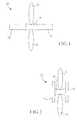
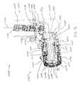
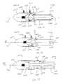
- FIG. 1is a schematic illustration of a medical device according to an embodiment of the invention adjacent two adjacent spinous processes.
- the medical device 10includes a proximal portion 12 , a distal portion 14 and a central portion 16 .
- the medical device 10has a first configuration in which it can be inserted between adjacent spinous processes S.
- the central portion 16is configured to contact the spinous processes S to prevent over-extension/compression of the spinous processes S. In some embodiments, the central portion 16 does not substantially distract the adjacent spinous processes S. In other embodiments, the central portion 16 does not distract the adjacent spinous processes S.
- the proximal portion 12 , the distal portion 14 and the central portion 16are coaxial (i.e., share a common longitudinal axis).
- the proximal portion 12 , the distal portion 14 and the central portion 16define a tube having a constant inner diameter.
- the proximal portion 12 , the distal portion 14 and the central portion 16define a tube having a constant outer diameter and/or inner diameter.
- the medical device 10can be moved from the first configuration to a second configuration as illustrated in FIG. 2 .
- the proximal portion 12 and the distal portion 14are positioned to limit lateral movement of the device 10 with respect to the spinous processes S.
- the proximal portion 12 and the distal portion 14are configured to engage the spinous process (i.e., either directly or through surrounding tissue) in the second configuration.
- the tissue surrounding the spinous processes Sis not illustrated.
- the proximal portion 12 , the distal portion 14 and the central portion 16are monolithically formed. In other embodiments, one or more of the proximal portion 12 , the distal portion 14 and the central portion 16 are separate components that can be coupled together to form the medical device 10 .
- the proximal portion 12 and distal portion 14can be monolithically formed and the central portion can be a separate component that is coupled thereto.
- the spinous processes Scan be distracted prior to inserting the medical device 10 .
- Distraction of spinous processesis discussed below.
- a trocarcan be used to define an access passage for the medical device 10 .
- the trocarcan be used to define the passage as well as distract the spinous processes S.
- the medical device 10is inserted percutaneously (i.e., through an opening in the skin) and in a minimally-invasive manner.
- the size of portions of the implantis expanded after the implant is inserted between the spinous processes. Once expanded, the size of the expanded portions of the implant is greater than the size of the opening.
- the size of the opening/incision in the skinmay be between 3 millimeters in length and 25 millimeters in length. In some embodiments, the size of the implant in the expanded configuration is between 3 and 25 millimeters.
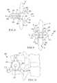
- FIG. 3is a schematic illustration of a deformable element 18 that is representative of the characteristics of, for example, the distal portion 14 of the medical device 10 in a first configuration.
- the deformable member 18includes cutouts A, B, C along its length to define weak points that allow the deformable member 18 to deform in a predetermined manner.
- the manner in which the deformable member 18 deforms under an applied loadcan be controlled and varied.
- the manner in which the deformable member 18 deformscan be controlled and varied.
- the length L between the cutouts A, B, Ci.e., the length of the material between the cutouts
- the manner in which the deform able member 18 deformscan be controlled and varied.
- FIG. 4is a schematic illustration of the expansion properties of the deformable member 18 illustrated in FIG. 3 .
- the deformable member 18deforms in a predetermined manner based on the characteristics of the deformable member 18 as described above.
- the deformable member 18deforms most at cutouts B and C due to the configuration of the cutout C and the short distance between cutouts B and C.
- the length of the deformable member 18 between cutouts B and Cis sized to fit adjacent a spinous process.
- the deformable member 18is stiffer at cutout A due to the shallow depth of cutout A. As indicated in FIG. 4 , a smooth transition is defined by the deformable member 18 between cutouts A and B. Such a smooth transition causes less stress on the tissue surrounding a spinous process than a more drastic transition such as between cutouts B and C.
- the dimensions and configuration of the deformable member 18can also determine the timing of the deformation at the various cutouts.
- the weaker (i.e., deeper and wider) cutoutsdeform before the stronger (i.e., shallower and narrower) cutouts.
- FIGS. 5 and 6illustrate a spinal implant 100 in a first configuration and second configuration, respectively.
- the spinal implant 100is collapsed in a first configuration and can be inserted between adjacent spinous processes.
- the spinal implant 100has a first expandable portion 110 , a second expandable portion 120 and a central portion 150 .
- the first expandable portion 110has a first end 112 and a second end 1140 .
- the second expandable portion 120has a first end 122 and a second end 124 .
- the central portion 150is coupled between second end 1140 and first end 122 .
- the spinal implant 100is monolithically formed.
- the first expandable portion 110 , the second expandable portion 120 and the central portion 150have a common longitudinal axis A along the length of spinal implant 100 .
- the central portion 150can have the same inner diameter as first expandable portion 110 and the second expandable portion 120 .
- the outer diameter of the central portion 150is smaller than the outer diameter of the first expandable portion 110 and the second expandable portion 120 .
- spinal implant 100is inserted percutaneously between adjacent spinous processes.
- the first expandable portion 110is inserted first and is moved past the spinous processes until the central portion 150 is positioned between the spinous processes.
- the outer diameter of the central portion 150can be slightly smaller than the space between the spinous processes to account for surrounding ligaments and tissue.
- the central portiondirectly contacts the spinous processes between which it is positioned.
- the central portion of spinal implant 100is a fixed size and is not compressible or expandable.
- the first expandable portion 110includes expanding members 115 , 117 and 119 . Between the expanding members 115 , 117 , 119 , openings 111 are defined. As discussed above, the size and shape of the openings 111 influence the manner in which the expanding members 115 , 117 , 119 deform when an axial load is applied.
- the second expandable portion 120includes expanding members 125 , 127 and 129 . Between the expanding members 125 , 127 , 129 , openings 121 are defined. As discussed above, the size and shape of the openings 121 influence the manner in which the expanding members 125 , 127 , 129 deform when an axial load is applied.
- first end 112 and second end 1140 of the first expandable portion 110move towards each other and expanding members 115 , 117 , 119 project substantially laterally away from the longitudinal axis A.
- first end 122 and second end 124 of the second expandable portion 120move towards one another and expanding members 125 , 127 , 129 project laterally away from the longitudinal axis A.
- the expanding members 115 , 117 , 119 , 125 , 127 , 129 in the second configurationform projections that extend to positions adjacent to the spinous processes between which the spinal implant 100 is inserted.
- the expanding members 115 , 117 , 119 , 125 , 127 , 129inhibit lateral movement of the spinal implant 100 , while the central portion 150 prevents the adjacent spinous processes from moving together any closer than the distance defined by the diameter of the central portion 150 .
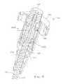
- a spinal implant 200 according to an embodiment of the inventionis illustrated in FIGS. 7-9 in various configurations.
- Spinal implant 200is illustrated in a completely collapsed configuration in FIG. 7 and can be inserted between adjacent spinous processes.
- the spinal implant 200has a first expandable portion 210 , a second expandable portion 220 and a central portion 250 .
- the first expandable portion 210has a first end 212 and a second end 214 .
- the second expandable portion 220has a first end 222 and a second end 224 .
- the central portion 250is coupled between second end 214 and first end 222 .
- the first expandable portion 210 , the second expandable portion 220 and the central portion 250have a common longitudinal axis A along the length of spinal implant 200 .
- the central portion 250can have the same inner diameter as first expandable portion 210 and the second expandable portion 220 .
- the outer diameter of the central portion 250is greater than the outer diameter of the first expandable portion 210 and the second expandable portion 220 .
- the central portion 250can be monolithically formed with the first expandable portion 210 and the second expandable portion 220 or can be a separately formed sleeve coupled thereto or thereupon.
- spinal implant 200is inserted percutaneously between adjacent spinous processes S.
- the first expandable portion 210is inserted first and is moved past the spinous processes S until the central portion 250 is positioned between the spinous processes S.
- the outer diameter of the central portion 250can be slightly smaller than the space between the spinous processes S to account for surrounding ligaments and tissue.
- the central portion 250directly contacts the spinous processes S between which it is positioned.
- the central portion 250 of spinal implant 200is a fixed size and is not compressible or expandable. In other embodiments, the central portion 250 can compress to conform to the shape of the spinous processes.
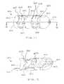
- the first expandable portion 210includes expanding members 215 , 217 and 219 . Between the expanding members 215 , 217 , 219 , openings 211 are defined. As discussed above, the size and shape of the openings 211 influence the manner in which the expanding members 215 , 217 , 219 deform when an axial load is applied. Each expanding member 215 , 217 , 219 of the first expandable portion 210 includes a tab 213 extending into the opening 211 and an opposing mating slot 218 . In some embodiments, the first end 212 of the first expandable portion 210 is rounded to facilitate insertion of the spinal implant 200 .
- the second expandable portion 220includes expanding members 225 , 227 and 229 . Between the expanding members 225 , 227 , 229 , openings 221 are defined. As discussed above, the size and shape of the openings 221 influence the manner in which the expanding members 225 , 227 , 229 deform when an axial load is applied. Each expanding member 225 , 227 , 229 of the second expandable portion 220 includes a tab 223 extending into the opening 221 and an opposing mating slot 228 .
- the spinal implantmoves to a partially expanded configuration as illustrated in FIG. 8 .
- first end 222 and second end 224 of the second expandable portion 220move towards one another and expanding members 225 , 227 , 229 project laterally away from the longitudinal axis A.
- the tab 223engages slot 228 and acts as a positive stop.
- the loadis transferred to the first expandable portion 210 .
- first end 212 and the second end 214then move towards one another until tab 213 engages slot 218 in the fully expanded configuration illustrated in FIG. 9 .
- expanding members 215 , 217 , 219project laterally away from the longitudinal axis A.
- the first expandable portion and the second expandable portionexpand simultaneously under an axial load.
- the order of expansion of the spinal implant 200can be controlled by varying the size of openings 211 and 221 .
- the opening 221is slightly larger than the opening 211 .
- the notches 226are slightly larger than the notches 216 .
- the second expandable portion 220will expand before the first expandable portion 210 under an axial load.
- the expanding members 215 , 217 , 219 , 225 , 227 , 229form projections that extend adjacent the spinous processes S.
- the expanding members 215 , 217 , 219 , 225 , 227 , 229inhibit lateral movement of the spinal implant 200 , while the central portion 250 prevents the adjacent spinous processes from moving together any closer than the distance defined by the diameter of the central portion 250 .
- each of the expanding members 215 , 217 , 219 , 225 , 227 , 229 proximal to the spinous process Sexpands such that portion P is substantially parallel to the spinous process S.
- the portion D of each of the expanding members 215 , 217 , 219 , 225 , 227 , 229 distal from the spinous process Sis angled such that less tension is imparted to the surrounding tissue.
- the expanding members 225 , 227 , 229are separate by approximately 120 degrees from an axial view as illustrated in FIG. 10 . While three expanding members are illustrated, two or more expanding members may be used and arranged in an overlapping or interleaved fashion when multiple implants 200 are inserted between multiple adjacent spinous processes. Additionally, regardless of the number of expanding members provided, the adjacent expanding members need not be separated by equal angles or distances.
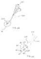
- the spinal implant 200is deformed by a compressive force imparted substantially along the longitudinal axis A of the spinal implant 200 .
- the compressive forceis imparted, for example, by attaching a rod (not illustrated) to the first end 212 of the first expandable portion 210 and drawing the rod along the longitudinal axis while imparting an opposing force against the second end 224 of the second expandable portion 220 .
- the opposing forcesresult in a compressive force causing the spinal implant 200 to expand as discussed above.
- the rod used to impart compressive force to the spinal implant 200can be removably coupled to the spinal implant 200 .
- the spinal implant 200can include threads 208 at the first end 212 of the first expandable portion 210 .
- the force opposing that imparted by the rodcan be applied by using a push bar (not illustrated) that is removably coupled to the second end 224 of the second expandable portion 220 .
- the push rodcan be aligned with the spinal implant 200 by an alignment notch 206 at the second end 224 .
- the spinal implant 200can also be deformed in a variety of other ways, using a variety of expansion devices (also referred to herein as insertion tools, deployment tools and/or removal tools). While various types of implants are illustrated with various types of expansion devices, the expansion devices described herein can be used with any of the implants described herein.
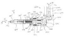
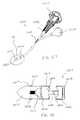
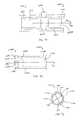
- FIGS. 11-16illustrate an expansion device 1500 (also referred to herein as an insertion tool or a deployment tool) according to an embodiment of the invention.
- an expansion device 1500also referred to herein as an insertion tool or a deployment tool
- any of the implants described herein, such as, for example, implant 200 (see FIG. 7 )can be used with the expansion device 1500 .
- the expansion device 1500includes a guide handle 1510 , a knob assembly 1515 , a shaft 1520 , a rod 1570 and an implant support portion 1530 .
- the expansion device 1500is used to insert an implant (not illustrated) in between adjacent spinous processes and expand the implant such that it is maintained in position between the spinous processes as described above.
- Both the guide handle 1510 and the knob assembly 1515can be grasped to manipulate the expansion device 1500 to insert the implant.
- the knob assembly 1515is configured such that as the knob assembly 1515 is actuated, the rod 1570 translates and/or rotates within the shaft 1520 ; when the rod 1570 translates, the implant (not illustrated) is moved between its collapsed configuration and its expanded configuration; when the rod 1570 rotates, the implant is disengaged from the rod 1570 .
- the implant support portion 1530includes a receiving member 1538 and a spacer 1532 .
- the receiving member 1538includes a side wall 1540 that is coupled to and supported by the distal end of the shaft 1520 .
- the side wall 1540defines an alignment protrusion 1536 and a receiving area 1542 configured to receive a portion of the spacer 1532 .
- the implantslides over spacer 1532 until its proximal end is received within a recess 1534 defined by the side wall 1540 and the outer surface of the spacer 1532 .
- the alignment protrusion 1536is configured to mate with a corresponding notch on the implant (see, e.g., alignment notch 206 in FIG. 7 ) to align the implant with respect to the expansion device.
- the spacer 1532ensures that the implant is aligned longitudinally during the insertion and expansion process.
- the spacer 1532can also be configured to maintain the shape of the implant during insertion and to prevent the expandable portions of the implant from extending inwardly during deployment of the implant.
- the spacer 1532can be constructed from a solid, substantially rigid material, such as stainless steel, having an outer diameter and length corresponding to the inner diameter and length of the implant.
- the expansion devicecan be configured to be used with implants that include an inner core configured to provide structural support to the implant (see, for example, FIGS. 17-23 ).
- the spacer of the insertion toolcan be configured to cooperate with the inner core of the implant to provide the alignment and structural support of the implant during insertion and expansion.
- the knob assembly 1515includes an upper housing 1517 that threadedly receives the shaft 1520 , an actuator knob 1550 and a release knob 1560 as best illustrated in FIG. 14 .
- Upper housing 1517includes internal threads 1519 that mate with external threads 1521 on shaft 1520 .
- the proximal end of rod 1570is coupled to the knob assembly 1515 by an adapter 1554 , which is supported by two thrust bearings 1552 .
- Actuator knob 1550is coupled to the upper housing 1517 and is engaged with the adapter 1554 such that when actuator knob 1550 is turned in the direction indicated by arrows E (see FIG.
- the rod 1570translates axially relative to the shaft 1520 towards the proximal end of the device 1500 , thereby acting as a draw bar and opposing the movement of the implant in the distal direction.
- the distal end of the implant support portion 1530imparts an axial force against the proximal end of the implant, while the rod 1570 causes an opposing force in the proximal direction.
- the forces imparted by the implant support portion and the rod 1570cause portions of the implant to expand in a transverse configuration such that the implant is maintained in position between the spinous processes as described above.
- the expansion device 1500can also be used to move the implant from its expanded configuration to its collapsed configuration by turning the actuator knob 1550 in the opposite direction.
- the release knob 1560is turned in the direction indicated by arrow R (see FIG. 13 ) thereby causing the rod 1570 to rotate within the shaft 1520 .
- the implantcan be disengaged from the rod 1570 .
- the implantis prevented from rotating by the alignment protrusion 1536 , which is configured to mate with a corresponding notch on the implant.
- knob assembly 1515is shown and described as including an actuator knob 1550 and a release knob 1560 that are coaxially arranged with a portion of the release knob 1560 being disposed within the actuator knob 1550 , in some embodiments, the release knob is disposed apart from the actuator knob. In other embodiments, the release knob and the actuator knob are not coaxially located. In yet other embodiments, the knob assembly 1515 does not include knobs having a circular shape, but rather includes levers, handles or any other device suitable for actuating the rod relative to the shaft as described above.
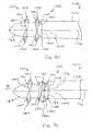
- FIGS. 17-23illustrate an implant 6610 according to another embodiment of the invention.
- the implant 6610can be moved between a collapsed configuration, as shown in FIGS. 17 and 18 , and an expanded configuration, as shown in FIGS. 19-23 .
- the implant 6610includes an outer shell 6670 having a distal portion 6612 , a proximal portion 6614 , and a central portion 6616 .
- the outer shell 6670defines a series of openings 6618 disposed between the distal portion 6612 and the central portion 6616 , and the proximal portion 6614 and the central portion 6616 .
- the outer shell 6670includes a series of tabs 6620 , a pair of which are disposed opposite each other, along the longitudinal axis of the implant 6610 , on either side of each opening 6618 .
- the outer shell 6670also includes expandable portions 6640 , which form extensions 6642 that extend radially from the outer shell 6670 when the implant 6610 is in the expanded configuration. As illustrated best in FIGS. 19-23 , the arrangement of the openings 6618 and the tabs 6620 effect the shape and/or size of the extensions 6642 .
- the opposing tabs 6620can be configured to engage each other when the implant 6610 is in the expanded configuration, thereby serving as a positive stop to limit the amount of expansion.
- the opposing tabs 6620can be configured to engage each other during the expansion process, thereby serving as a positive stop, but remain spaced apart when the implant 6610 is in the expanded configuration (see, for example, FIGS. 19-23 ).
- the elastic properties of the extensions 6642can cause a slight “spring back,” thereby causing the opposing tabs 6620 to be slightly spaced apart when the expansion device (also referred to as an insertion tool or a deployment tool) is disengaged from the implant 6610 .
- the expandable portions 6640are contoured to extend slightly radially from remaining portions of the outer shell 6670 . In this manner, the expandable portions 6640 are biased such that when a compressive force is applied, the expandable portions 6640 will extend outwardly from the outer shell 6670 .
- the expandable portions 6640can be biased using any suitable mechanism. In some embodiments, for example, the expandable portions can be biased by including a notch in one or more locations along the expandable portion, as previously described. In other embodiments, the expandable portions can be biased by varying the thickness of the expandable portions in an axial direction.
- the expandable portionscan be stressed or bent prior to insertion such that the expandable portions are predisposed to extend outwardly when a compressive force is applied to the implant.
- the radius of the expandable portionsis greater than that of the remaining portions of the implant (e.g., the remaining cylindrical portions of the implant).
- the implant 6610also includes an inner core 6672 disposed within a lumen 6658 defined by the outer shell 6670 .
- the inner core 6672is configured to maintain the shape of the implant 6610 during insertion, to prevent the expandable portions from extending inwardly into a region inside of the outer shell 6670 during deployment and/or to maintain the shape of the central portion 6616 once the implant is in its desired position.
- the inner core 6670can be constructed to provide increased compressive strength to the outer shell 6670 .
- the inner core 6672can provide additional structural support to outer shell 6670 (e.g., in a direction transverse to the axial direction) by filling at least a portion of the region inside outer shell 6670 (e.g., lumen 6658 ) and contacting the walls of outer shell 6670 . This can increase the amount of compressive force that can be applied to the implant 6610 while the implant 6610 still maintains its shape and, for example, the desired spacing between adjacent spinous processes.
- the inner core 6672can define a lumen 6673 , while in other embodiments, the inner core 6672 can have a substantially solid construction.
- the inner core 6672is fixedly coupled to the outer shell 6670 with a coupling portion 6674 , which is configured to be threadedly coupled to the distal portion 6612 of the outer shell 6670 .
- the distal end of the coupling portion 6674 of the inner core 6672includes an opening 6675 configured to receive a tool configured to deform the distal end of the coupling portion 6674 .
- the coupling portion 6674can be deformed or peened to ensure that the inner core 6672 does not become inadvertently decoupled from the outer shell 6670 .
- an adhesivesuch as a thread-locking compound can be applied to the threaded portion of the coupling portion 6674 to ensure the that the inner core 6672 does not inadvertently become decoupled from the outer shell 6670 .
- the inner core 6672can be coupled to the outer shell 6670 by any suitable means.
- the inner core 6672can be coupled to the central portion 6616 of the outer shell 6670 by, for example, a friction fit.
- the inner core 6672can be coupled to the outer shell 6670 by an adhesive.
- the inner core 6672can have a length such that the inner core 6672 is disposed within the lumen 6658 along substantially the entire length of the outer shell 6670 or only a portion of the length of the outer shell 6670 .
- the proximal portion of the inner core 6672includes an opening 6673 configured to receive a portion of an expansion device 7500 (also referred to as an insertion tool or a deployment tool), as shown in FIGS. 24-31 .
- the expansion device 7500is similar to the expansion device 1500 shown and described above (see e.g. FIGS. 11-16 ).
- the expansion device 7500differs, however, from expansion device 1500 in that the expansion device 7500 includes spacer 7532 configured to cooperate with the inner core 6672 of the implant 6610 .
- the threaded portion of rod 7570 of the expansion device 7500removably engages to the internal threads 6676 of the inner core 6672 of the implant 6610 , rather than coupling directly to the distal portion of the implant (as shown in FIGS. 15 and 16 ).
- the inner core 6672is shown as being threadedly coupled to the expansion device 7500
- the inner core 6672can be removably coupled to the expansion device 7500 by any suitable means, such as a protrusion and detent arrangement.
- the implant 6610is positioned on the implant support portion 7530 of the expansion tool 7500 (see FIGS. 24 and 25 ), the implant is inserted into the patient's body and disposed between adjacent spinous processes.
- the expansion devicecan be used to move the inner core 6672 axially towards the proximal portion 6614 of the implant 6610 while simultaneously maintaining the position of the proximal portion 6614 of the implant 6610 , as shown in FIGS. 29 and 31 . In this manner, a compressive force is applied along the longitudinal axis of the outer shell 6670 , thereby causing the outer shell 6670 to fold or bend to form extensions 6642 as described above.
- a portion of the spacer 7532is received within the receiving area 7542 of the support portion 7530 as the implant 6610 is placed in the expanded configuration.
- the expansion deviceis actuated in the opposite direction to impart an axial force on the distal portion 6612 of the outer shell 6610 in a distal direction, moving the distal portion 6612 distally, and moving the implant 6610 to the collapsed configuration.
- the implant 6610can be disengaged from the expansion device 7500 by disengaging the distal portion of the rod 7570 from the opening 6673 .
- the rod 7570can be disengaged by actuating the knob assembly 7515 rotate the rod 7570 relative to the shaft 7520 , as discussed above.
- the outer shell 6670can have a cylindrical shape having a length of approximately 34.5 mm (1.36 inches) and a diameter between 8.1 and 14.0 mm (0.32 and 0.55 inches).
- the wall thickness of the outer shellcan be approximately 5.1 mm (0.2 inches).
- the inner core 6672can have a cylindrical shape having an overall length of approximately 27.2 mm (1.11 inches) and a diameter between 8.1 and 14.0 mm (0.32 and 0.55 inches).
- the shape and size of the openings 6618 located adjacent the distal portion 6612can be the same as that for the openings 6618 located adjacent the proximal portion 6614 .
- the openings 6618can have different sizes and/or shapes.
- the openings 6618can have a length of approximately 11.4 mm (0.45 inches) and a width between 4.6 and 10 mm (0.18 and 0.40 inches).
- the shape and size of the tabs 6620can be uniform or different as circumstances dictate.
- the longitudinal length of the tabs 6620 located adjacent the proximal portion 6614can be shorter than the longitudinal length of the tabs 6620 located adjacent the distal portion 6612 .
- the longitudinal length of the tabscan be the same.
- the longitudinal length of the tabscan be between 1.8 and 2.8 mm (0.07 and 0.11 inches).
- the end portions of opposing tabs 6620can have mating shapes, such as mating radii of curvature, such that the opposing tabs 6620 engage each other in a predefined manner.
- the expandable portions 6640 and the resulting extensions 6642can be of any suitable shape and size.
- the expandable portionscan have a longitudinal length of approximately 11.4 mm (0.45 inches) and a width between 3.6 and 3.8 mm (0.14 and 0.15 inches).
- size and/or shape of the expandable portions located adjacent the proximal portion 6614can be different than the size and/or shape of the tabs 6620 located adjacent the distal portion 6612 .
- the expandable portions 6640can be contoured to extend slightly radially from the outer shell 6670 .
- the expandable portionscan have a radius of curvature of approximately 12.7 mm (0.5 inches) along an axis normal to the longitudinal axis of the implant.
- the expandable portions 6640 and the outer shell 6670are monolithically formed. In other embodiments, the expandable portions 6640 and the outer shell 6670 are formed from separate components having different material properties. For example, the expandable portions 6640 can be formed from a material having a greater amount of flexibility, while the outer shell 6670 can be formed from a more rigid material. In this manner, the expandable portions 6640 can be easily moved from the collapsed configuration to the expanded configuration, while the outer shell 6670 is sufficiently strong to resist undesirable deformation when in use.
- an apparatusin one embodiment, includes a first body coupled to a second body.
- the first body and the second bodycollectively are configured to be releasably coupled to an implant device configured to be disposed between adjacent spinous processes.
- a first engaging portionis coupled to the first body, and a second engaging portion is coupled to the second body.
- the first engaging portion and/or the second engaging portionis configured to be received within a first opening defined by the implant device.
- the first bodyconfigured to be moved relative to the second body such that a distance between the first engaging portion and the second engaging portion is moved between a first distance and a second distance, and simultaneously a length of the implant device is moved between a first length and a second length.
- a kitin another embodiment, includes an implant that is reconfigurable between an expanded configuration and a collapsed configuration while disposed between adjacent spinous processes.
- the implanthas a longitudinal axis and defines an opening.
- a deployment toolis configured to be releasably coupled to the implant.
- the deployment toolincludes an engaging portion configured to be removably received within the opening of the implant and extend in a transverse direction relative to the longitudinal axis when the deployment tool is coupled to the implant.
- the deployment toolis configured to move the implant between the collapsed configuration and the expanded configuration while the implant is disposed between the adjacent spinous processes.
- FIGS. 32 and 33are schematic illustrations of a medical device according to an embodiment of the invention positioned between two adjacent spinous processes.
- FIG. 32illustrates the medical device in a first configuration
- FIG. 33illustrates the medical device in a second configuration.
- the medical device 6000includes an implant 6010 and a deployment tool 6020 .
- the implant 6010includes a distal portion 6012 , a proximal portion 6014 , and a central portion 6016 .
- the implant 6010is configured to be inserted between adjacent spinous processes S.
- the central portion 6016is configured to contact and provide a minimum spacing between the spinous processes S when adjacent spinous processes S move toward each other during their range of motion to prevent over-extension/compression of the spinous processes S.
- the central portion 6016does not substantially distract the adjacent spinous processes S. In other embodiments, the central portion 6016 does distract the adjacent spinous processes S.
- the implant 6010 and the deployment tool 6020can each be inserted into a patient's back and moved in between adjacent spinous processes from the side of the spinous processes (i.e., a posterior-lateral approach). The use of a curved insertion shaft assists in the use of a lateral approach to the spinous processes S.
- the implant 6010has a collapsed configuration in which the proximal portion 6014 , the distal portion 6012 and the central portion 6016 share a common longitudinal axis.
- the proximal portion 6014 , the distal portion 6012 and the central portion 6016define a tube having a constant inner diameter.
- the proximal portion 6014 , the distal portion 6012 and the central portion 6016define a tube having a constant outer diameter and/or inner diameter.
- the proximal portion 6014 , the distal portion 6012 and/or the central portion 6016have different inner diameters and/or outer diameters.
- the implant 6010can be moved from the collapsed configuration to an expanded configuration, as illustrated in FIG. 33 .
- the proximal portion 6014 and the distal portion 6012each have a larger outer perimeter (e.g., outer diameter) than when in the collapsed configuration, and the proximal portion 6014 and the distal portion 6012 each have a larger outer perimeter (e.g., outer diameter) than the central portion 6016 .
- the proximal portion 6014 and the distal portion 6012are positioned to limit lateral movement of the implant 6010 with respect to the spinous processes S.
- the proximal portion 6014 and the distal portion 6012are configured to engage the spinous process (i.e., either directly or through surrounding tissue and depending upon the relative position of the adjacent spinous processes S) in the expanded configuration.
- the tissue surrounding the spinous processes Sis not illustrated.
- the proximal portion 6014 , the distal portion 6012 and the central portion 6016are monolithically formed. In other embodiments, one or more of the proximal portion 6014 , the distal portion 6012 and/or the central portion 6016 are separate components that can be coupled together to form the implant 6010 .
- the proximal portion 6014 and distal portion 6012can be monolithically formed and the central portion 6016 can be a separate component that is coupled thereto. These various portions can be coupled, for example, by a friction fit, welding, adhesive, etc.
- the implant 6010is configured to be coupled to the deployment tool 6020 .
- the deployment tool 6020includes an elongate member 6022 and two or more engaging portions 6024 . In the embodiment shown in FIGS. 32 and 33 , there are two engaging portions 6024 - 1 and 6024 - 2 shown, but it should be understood that more than two engaging portions 6024 can be included.
- the elongate member 6022can include a first body portion 6026 coupled to a second body portion 6028 . In some embodiments, the first body portion 6026 is threadedly coupled to the second body portion 6028 . The first body portion 6026 and the second body portion 6028 are configured to be moved relative to each other.
- a threaded connection between the first body portion 6026 and the second body portion 6028can be used to decrease or increase a distance between the first body portion 6026 and the second body portion 6028 .
- the first body portion 6026 and the second body portion 6028can be a variety of different shapes and sizes, and can be the same shape and/or size, or have a different shape and/or size than each other.
- the first body portionincludes a straight distal end and a straight proximal end
- the second body portionincludes a straight proximal end and a curved or rounded distal end.
- the curved distal endcan assist with the insertion of the deployment tool into a lumen of an implant and also with the insertion of the medical device into a portion of a patient's body.
- the first engaging portion 6024 - 1can be coupled to the first body portion 6026 and the second engaging portion 6024 - 2 can be coupled to the second body portion 6028 .
- the engaging portions 6024can be, for example, substantially rectangular, square, circular, oval, semi-circular, or quarter-moon shaped.
- the engaging portions 6024can be spring-loaded devices coupled to the elongate member 6022 of the deployment tool 6020 , such that the engaging portions 6024 are biased into a position transverse to a longitudinal axis A defined by the elongate member 6022 and extending from an outer surface of the elongate member 6022 .
- the engaging portions 6024can be moved or collapsed to a position substantially below the outer surface of the elongate member 6022 .
- the engaging portions 6024can alternatively be coupled to an actuator (not shown) configured to move the engaging portions 6024 from a position transverse to the longitudinal axis A and extending from an outer surface of the elongate member 6022 , to a position substantially below the outer surface of the elongate member 6022 .
- FIGS. 34-36illustrate the movement of an engaging portion 6024 as it passes by a spinous process S when an implant and deployment tool (collectively also referred to as medical device) are coupled together and being inserted between adjacent spinous processes.
- an engaging portion 6024 extending from a proximal portion of an implantmay come into contact with a spinous process (or other tissue).
- the engaging portion 6024can be moved downward (as described above) so as to clear the spinous process.
- FIG. 34illustrates an engaging portion 6024 having a spring-biased construction.
- the engaging portion 6024includes a curved portion 6048 that initially contacts the spinous process S as the medical device is being inserted adjacent a spinous process S. As the curved portion 6048 contacts the spinous process S, the engaging portion 6024 is moved downward at least partially into an interior of the implant 6010 , as shown in FIG. 35 . The engaging portion 6024 moves back to an extended position (e.g., extending transversely from a surface of the implant 6010 ) after the engaging portion clears the spinous process S, as shown in FIG. 36 , due to the bias of the spring (not shown).
- an extended positione.g., extending transversely from a surface of the implant 6010
- the deployment tool 6020can be used to move the implant 6010 from the collapsed configuration to the expanded configuration, and vice versa, as will be discussed in more detail below.
- the first body portion 6026 and the second body portion 6028are collectively configured to be inserted at least partially into a lumen (not shown in FIGS. 32 and 33 ) of the implant 6010 , such that at least one engaging portion 6024 extends through an opening (not shown in FIGS. 32 and 33 ) defined by the implant 6010 .
- the implant 6010can be configured with one or more such openings, each of which is configured to receive an engaging portion 6024 disposed on the elongate member 6022 (e.g., the first body portion 6026 or the second body portion 6028 ).
- the openings defined by the implant 6010can be, for example, the openings can be circular, oval, square, rectangular, etc.
- FIG. 37illustrates an example of an implant 6110 defining curved rectangular openings 6136
- FIG. 47illustrates an implant 6310 defining curved round or circular openings 6336 .
- the openingsare at least partially defined by an edge (not shown in FIGS. 32 and 33 ) on the implant 6010 .
- the engaging portions 6024 on the deployment tool 6020include a surface (not shown in FIGS. 32 and 33 ) that is configured to engage or contact the edge of the openings of the implant 6010 when the elongate member 6022 is inserted into the lumen of the implant 6010 .
- the spinous processes Scan be distracted prior to inserting the implant 6010 .
- a trocarcan be used to define an access passage for the implant 6010 .
- the trocarcan be used to define the passage as well as distract the spinous processes S.
- the implant 6010can be inserted percutaneously and advanced between the spinous processes, distal end 6012 first, until the central portion 6016 is located between the spinous processes S.
- the implant 6010can be coupled to the deployment tool 6020 prior to being inserted between the adjacent spinous processes.
- the implant 6010can be inserted between adjacent spinous processes without being coupled to the deployment tool 6020 . In the latter configuration, after the implant 6010 is disposed between the adjacent spinous processes, the deployment tool 6020 can be inserted into the lumen defined by the implant 6010 .
- the implant 6010can be moved to the second configuration (i.e., the expanded configuration) by actuating the deployment tool 6020 .
- the first body portion 6026is positioned at a first distance from the second body portion 6028
- the first engaging portion 6024 - 1is positioned at a first distance from the second engaging portion 6024 - 2 , as shown in FIG. 32 .
- the deployment tool 6020can then be actuated at a proximal end portion (e.g., by turning a handle) (not shown in FIGS.
- the surface (described above and described in more detail below) on the engaging portions 6024imparts a force on the edge (described above and described in more detail below) of the opening defined by the implant causing the implant to move from the collapsed configuration to the expanded configuration.
- the deployment tool 6020is configured such that the deployment tool 6020 can be removed from the implant 6010 after the implant has been moved to the expanded configuration.
- the implantcan remain disposed between the spinous processes indefinitely or removed as needed.
- the deployment tool 6020can be reinserted into the lumen of the implant 6010 and actuated in an opposite direction to cause the implant 6010 to be moved from the expanded configuration back to the collapsed configuration.
- the implantIn the collapsed configuration, the implant can be removed from the patient's body or repositioned to a new location between the spinous processes.
- the implant 6010is inserted percutaneously (i.e., through an opening in the skin) and in a minimally-invasive manner.
- the sizes of portions of the implantare expanded after the implant is inserted between the spinous processes. Once expanded, the sizes of the expanded portions of the implant are greater than the size of the opening.
- the size of the opening/incision in the skincan be between 3 millimeters in length and 25 millimeters in length across the opening. In some embodiments, the size of the implant in the expanded configuration is between 3 and 25 millimeters across the opening.
- FIGS. 37-39illustrate an implant according to an embodiment of the invention.
- An implant 6110includes a proximal portion 6114 , a distal portion 6112 , and a central portion 6116 .
- the implant 6110also defines multiple openings 6132 on an outer surface of the implant 6110 .
- the openings 6132are in communication with a lumen 6158 (shown in FIG. 44 ) defined by the implant 6110 .
- the openings 6132are partially defined by a first edge 6136 and a second edge 6138 .
- the implant 6110includes expandable portions disposed at the distal portion 6112 and the proximal portion 6114 .
- the expandable portions 6140can be coupled to the implant 6110 or formed integral with the implant 6110 , as shown in FIG. 46 .
- elongated slots 6134can be defined on an outer surface of the implant 6110 .
- the elongated slots 6134create weakened areas on the implant 6110 that allow the expandable portions 6140 to fold when exposed to axial force, forming extensions 6142 , as shown in FIG. 38 .
- the implant 6110can be inserted between adjacent spinous processes (not shown) in a collapsed configuration, as shown in FIG. 37 , and then moved to an expanded configuration, as shown in FIG. 38 .
- the implant 6110can then be moved back to a collapsed configuration as shown in FIG. 39 , which illustrates the expandable portions 6140 in a partially collapsed configuration.
- FIG. 39shows a partially collapsed configuration, in some embodiments, the implant can be moved back to the collapsed configuration as shown in FIG. 37 .
- the deployment tool 6120includes an elongate member 6122 coupled to a handle 6144 .
- the elongate member 6122includes a first body portion 6126 coupled to a second body portion 6128 through a threaded coupling 6150 .
- a pair of engaging portions 6124 - 1are disposed on the first body portion 6126
- a pair of engaging portions 6124 - 2are disposed on the second body portion 6128 .
- the engaging portions 6124 - 1 and 6124 - 2(also collectively referred to as engaging portions 6124 ) include a surface 6146 and a rounded portion 6148 .
- the threaded coupling 6150 between the first body portion 6126 and the second body portion 6128is used to move the first body portion 6126 and the second body portion 6128 such that a distance between the first body portion 6126 and the second body portion 6128 is changed.
- FIG. 41illustrates a first distance d- 1 between the first body portion 6126 and the second body portion 6128
- FIG. 42illustrates a second distance d- 2 between the first body portion 6126 and the second body portion 6128 .
- a distance between the engaging portions 6124 - 2 and 6124 - 2is also changed.
- the first body portion 6126 and the second body portion 6128are collectively disposed within the lumen 6158 of the implant 6110 , such that the engaging portions 6124 extend through the openings 6132 and transverse to an axis B defined by the implant 6110 , as shown in FIGS. 43-45 .
- the surface 6146 of the engaging portions 6124is configured to contact the edge 6136 of the openings 6132 .
- FIGS. 43 and 44illustrate the first body portion 6126 and the second body portion 6128 disposed within the lumen of the implant 6110 , when the implant is in a collapsed configuration.
- the first body portion 6126is at a first distance from the second body portion 6128
- the engaging portions 6124 - 1are at a first distance from the engaging portions 6124 - 2
- the implanthas a first length L- 1 .
- the deployment tool 6120can be actuated to move the implant 6110 to the expanded configuration, as shown in FIG. 45 .
- the deployment tool 6120is actuated, the first body portion 6126 is moved closer to the second body portion 6128 , and the engaging portions 6124 - 1 are moved closer to the engaging portions 6124 - 2 .
- the surface 6146 on the engaging portions 6124impart a force on the edge 6136 of the openings 6132 , which axially compresses the implant 6110 until the implant 6110 has a second length L- 2 , as shown in FIG. 45 .
- the deployment tool 6120can be reconfigured such that the surface 6146 of the engaging portions 6124 are positioned facing an opposite direction and configured to contact the edge 6138 of the implant 6110 , as shown in FIG. 51 .
- the engaging portions 6124can be, for example, removed and re-coupled to the elongate member 6122 (e.g., the first body portion 6126 and the second body portion 6128 ) such that the same engaging portions 6124 are simply repositioned.
- a second deployment toolcan be used having engaging portions positioned in the opposite direction.
- the deployment toolis inserted into the lumen 6158 of the implant 6110 as done previously, such that the engaging portions 6124 extend through the openings 6132 of the implant 6110 and the surface 6146 contacts the edge 6136 of the implant 6110 .
- the deployment tool 6120is then actuated in an opposite direction (e.g., turned in an opposite direction) such that the first body portion 6126 and the second body portion 6128 are threadedly moved further away from each other.
- the engaging portions 6124 - 1are moved further away from the engaging portions 6124 - 2 , and the surface 6146 of the engaging portions 6124 impart a force on the edge 6138 (instead of edge of 6136 ) of openings 6132 , which moves the implant 6110 back to the collapsed or straightened configuration.
- the implant described in all of the embodiments of the inventioncan be repeatedly moved between the collapsed and expanded configurations as necessary to insert, reposition or remove the implant as desired.
- FIG. 48illustrates a deployment tool according to another embodiment of the invention.
- a deployment tool 6220includes an elongate member 6222 having a first body portion 6226 coupled to a second body portion 6228 through a threaded coupling 6250 .
- the deployment tool 6220includes two sets of four (8 total) engaging portions 6224 (only six engaging portions are shown in FIG. 48 ).
- a first set of engaging portions 6224 - 1are coupled to the first body portion 6226
- a second set of engaging portions 6224 - 2are coupled to the second body portion 6228 .
- the engaging portions 6224include a first surface 6246 and a second surface 6252 .
- the first surface 6246is configured to contact an edge of an opening defined on the implant (such as edge 6136 on implant 6110 ), and the second surface 6252 is configured to contact an opposite edge on the opening defined by the implant (such as edge 6138 on implant 6110 ).
- the deployment tool 6220can be inserted into an implant and used to move the implant between a collapsed configuration and an expanded configuration without having to reposition the engaging portions 6224 , or use a second deployment tool.
- the deployment tool 6220is actuated in a first direction.
- the deployment tool 6220is actuated in an opposite direction (e.g., turned in an opposite direction).
- the surface 6246 of the engaging portions 6224impart a force on an edge of an opening (e.g., edge 6136 on implant 6110 ), causing the implant to be axially compressed, as previously described.
- the surface 6252 of the engaging portions 6224imparts a force on an opposite edge of the opening (e.g., edge 6138 on implant 6110 ), causing the implant to be substantially straightened as previously described.
- FIG. 49illustrates a deployment tool according to another embodiment of the invention.
- a deployment tool 6420is similar to the deployment tool 6220 described above, except in this embodiment, there are only two sets of two engaging portions 6424 (4 total).
- the engaging portions 6424are similar to the engaging portions 6224 except the engaging portions 6424 are substantially rectangular shaped.
- the engaging portions 6424include a surface 6446 configured to contact an edge of an opening defined by an implant, and a surface 6452 configured to contact an opposite edge of the opening defined by the implant.
- FIG. 50illustrates a deployment tool according to yet another embodiment of the invention.
- a deployment tool 6520is similarly constructed and functions similarly to the previous embodiments.
- the deployment tool 6520includes an elongate member 6522 that includes a first body portion 6526 and a second body portion 6528 .
- the first body portion 6526 and the second body portion 6528are smaller than illustrated in the previous embodiments, and engaging portions 6524 are coupled to the first body portion 6526 and the second body portion 6528 that are more elongate than previously shown.
- FIGS. 52 and 53are schematic illustrations of a deployment tool 11500 according to an embodiment of the invention in a first configuration and a second configuration, respectively.
- the deployment tool 11500includes an elongate member 11520 and a locking member 11506 .
- the elongate member 11520has a distal end portion 11544 and defines a center line CL.
- the elongate member 11520which can be, for example, a shaft of any type shown and described above, is configured to engage a spinal implant 11100 .
- the locking member 11506is disposed at the distal end portion 11544 of the elongate member 11520 and can be moved relative to the elongate member 11520 between a first position ( FIG. 52 ) and second position ( FIG.
- the locking member 11506can translate relative to the elongate member 11520 between the first position and the second position in a direction substantially perpendicular to the center line CL.
- the deployment tool 11500can maintain a position of the spinal implant 11100 such that the spinal implant 11100 can be inserted, removed and/or repositioned within the body.
- the deployment tool 11500can prevent the spinal implant 11100 from rotating relative to the elongate member 11520 when the locking member 11506 is in the second position.
- the deployment tool 11500can prevent the spinal implant 11100 from translating (e.g., moving distally and/or proximally) relative to the elongate member 11520 when the locking member 11506 is in the second position.
- FIG. 54shows a deployment tool 12500 according to an embodiment of the invention.
- the deployment tool 12500includes an outer shaft assembly 12520 having a proximal shaft 12543 and a distal shaft 12544 joined together by a coupling 12545 .
- the proximal shaft 12543defines a center line CL p that is substantially normal to a center line CL D defined by the distal shaft 12544 , as shown in FIG. 56 .
- a knob 12515is disposed at the proximal end portion 12543 of the outer shaft assembly 12520 .
- a connector 12505is disposed at the distal end portion 12544 of the outer shaft assembly 12520 .
- the connector 12505is configured to removably connect the distal end portion 12544 of the outer shaft assembly 12520 to a spinal implant 6610 ′ such that the spinal implant 6610 ′ can be manipulated during insertion into, removal from and/or repositioning within the body.
- the spinal implant 6610 ′which is similar to the spinal implant 6610 shown and described above with reference to FIGS. 17-23 , includes an outer shell 6670 ′ having a distal portion 6612 ′ and a proximal portion 6614 ′.
- the outer shell 6670 ′defines a series of openings and has a series of expandable portions that form extensions 6642 ′ that extend outwardly from the outer shell 6670 ′ when the implant 6610 ′ is in the expanded configuration.
- the proximal end portion 6614 ′ of the outer shell 6670 ′defines three notches 6606 ′ that can be used, for example, to align the implant with the deployment tool 12500 , as described above.
- the outer shell 6670 ′ of the spinal implant 6610 ′also defines a series of openings 6607 ′ that can be used to couple the proximal end portion 6614 ′ of the spinal implant 6610 ′ to the deployment tool 12500 , as described herein.
- the spinal implant 6610 ′also includes an inner core 6672 ′ disposed within the outer shell 6670 ′.
- the inner core 6672 ′is configured to maintain the shape of the implant 6610 ′ during insertion, to prevent the expandable portions from extending inwardly into a region inside of the outer shell 6670 ′ during deployment and/or to maintain the shape of the central portion 6616 ′ once the implant is in its desired position.
- the proximal portion of the inner core 6672 ′defines an opening 6673 ′ configured to receive a portion of an expansion device (also referred to as an insertion tool or a deployment tool), such as expansion device 7500 shown and described above with reference to FIGS. 24-31 .
- an expansion devicealso referred to as an insertion tool or a deployment tool
- the connector 12505includes three locking members 12506 (only one shown in FIG. 56 ), such as for example spherical members, an outer sleeve 12590 and an inner sleeve 12580 .
- the locking members 12506are disposed within openings 12547 defined by the distal shaft 12544 of the outer shaft assembly 12520 (see FIG. 57 ).
- the locking members 12506are configured to move within the opening 12547 in a direction substantially perpendicular to the center line CL D of the distal shaft 12544 of the outer shaft assembly 12520 such that the deployment tool 12500 can be removably coupled to the spinal implant 6110 ′.
- the locking members 12506are configured to translate relative to the distal shaft 12544 in a direction substantially perpendicular to the center line CL D of the distal shaft 12544 of the outer shaft assembly 12520 .
- the outer sleeve 12590is slidably disposed about the distal shaft 12544 of the outer shaft assembly 12520 .
- the outer sleeve 12590includes an actuation surface 12591 and a retention surface 12592 .
- the actuation surface 12591 and/or the retention surface 12592can be a curved surface (e.g., the surface of a cylinder or cone) or a planar surface. As shown in FIGS. 56 and 61 , the actuation surface 12591 is at an acute angle with respect to the center line CL D .
- the retention surface 12592is substantially parallel to the center line CL D .
- the outer sleeve 12590has an extended position (see FIGS.
- the retention surface 12592engages the locking members 12506 to prevent the locking members 12506 from moving out from the openings 12547 . In this manner, the retention surface 12592 of the outer sleeve 12590 retains the locking members 12506 within the openings 6607 ′ of the spinal implant 6610 ′.
- actuation surface 12591is at an acute angle with respect to the center line CL D (e.g., the direction of motion of the outer sleeve 12590 )
- a component of the force transmitted via the actuation surface 12591 to the locking members 12506has an inward direction that is substantially normal to the center line CL D .
- outer sleeve 12590actuates the locking members 12506 inwardly in a direction that is substantially normal to the center line CL D when the outer sleeve 12590 is moved from its retracted position to its extended position.
- the outer sleeve 12590is coupled to the outer shaft assembly 12520 by a pin 12549 that extends from the distal shaft 12544 of the outer shaft assembly 12520 .
- a portion of the pin 12549is received within an elongated opening 12594 (see FIG. 58 ) defined by the outer sleeve 12590 .
- a portion of the pin 12549engages the ends of the elongated opening 12594 to limit the distance through which the outer sleeve 12590 can move with respect to the distal shaft 12544 of the outer shaft assembly 12520 when moving between the extended position and the retracted position. Said another way, when the outer sleeve 12590 is in the retracted position, as shown in FIG.
- the pin 12549is in contact with a distal end of the elongated opening 12594 .
- the pin 12549is in contact with a proximal end of the elongated opening 12594 . Accordingly, the distance through which the outer sleeve 12590 can move with respect to the outer shaft assembly 12520 is approximately the length of the elongated opening 12594 along a direction parallel to the center line CL D .
- the inner sleeve 12580cooperates with the outer sleeve 12590 to actuate and/or retain the locking members 12506 to removably couple the deployment tool 12500 to the spinal implant 6110 ′.
- the inner sleeve 12580is slidably disposed within the distal shaft 12544 of the outer shaft assembly 12520 .
- the inner sleeve 12580includes an outer surface 12586 and an inner surface 12585 .
- the inner surface 12585 of the inner sleeve 12580includes a flatted surface 12583 and defines an opening within which a drive member 12532 is disposed.
- the drive member 12532can be monolithically formed with the remaining portions of the inner sleeve 12580 .
- the outer surface 12586 of the inner sleeve 12580defines a protrusion 12582 and a retention surface 12584 .
- the protrusion 12582is received within a slot 12556 defined by the distal shaft 12544 of the outer shaft assembly 12520 to prevent the inner sleeve 12580 from rotating relative to the distal shaft 12544 of the outer shaft assembly 12520 while allowing the inner sleeve 12580 to move in a direction parallel to the center line CL D .
- the inner sleeve 12580has an extended position (see FIG. 56 ) and a retracted position (see FIGS. 61 and 62 ).
- the retention surface 12584engages the locking members 12506 to prevent the locking members 12506 from moving into the openings 12547 .
- the retention surface 12584 of the inner sleeve 12580maintains the position of the locking members 12506 outwardly against the retention surface 12592 of the outer sleeve 12590 , thereby preventing the outer sleeve 12590 from moving from its retracted position ( FIG. 56 ) to its extended position ( FIGS. 61 and 62 ).
- the outer sleeve 12590is biased towards its extended position by a spring 12509 disposed between a shoulder surface 12555 of the distal shaft 12544 of the outer shaft assembly 12520 (see FIG. 57 ) and the spring engagement surface 12593 of the outer sleeve 12590 (see FIG. 56 ).
- the inner sleeve 12580is biased towards its extended position by a spring 12507 disposed between a surface of a miter gear 12565 (shown in FIG. 56 ) disposed within the outer shaft assembly 12520 and the end of the inner sleeve 12580 .
- the deployment tool 12500includes an inner shaft assembly 12561 having a proximal shaft 12562 and a distal shaft 12563 .
- the proximal shaft 12562 of the inner shaft assembly 12561is movably disposed within the proximal shaft 12543 of the outer shaft assembly 12520 such that the proximal shaft 12562 of the inner shaft assembly 12561 is concentric with the center line CL p .
- the distal shaft 12563 of the inner shaft assembly 12561is movably disposed within the distal shaft 12544 of the outer shaft assembly 12520 such that the distal shaft 12563 of the inner shaft assembly 12561 is concentric with the center line CL D .
- the knob 12515is coupled to the proximal shaft 12562 of the inner shaft assembly 12561 such that the proximal shaft 12562 of the inner shaft assembly 12561 rotates about the center line CL p as shown by the arrow DD in FIG. 62 when the knob 12515 is rotated.
- the proximal shaft 12562 of the inner shaft assembly 12561is operatively coupled to the distal shaft 12563 of the inner shaft assembly 12561 by two miter gears 12565 .
- the miter gears 12565are coupled to the proximal shaft 12562 of the inner shaft assembly 12561 and the distal shaft 12563 of the inner shaft assembly 12561 by fasteners 12566 .
- the miter gears 12565are configured to rotate with the outer shaft assembly 12520 and are supported by bearing surfaces 12558 defined by the outer shaft assembly 12520 . In this manner, when the proximal shaft 12562 of the inner shaft assembly 12561 rotates about the center line CL p , the distal shaft 12563 of the inner shaft assembly 12561 rotates about the center line CL D , as shown by the arrow EE in FIG. 62 .
- a drive member 12532is coupled to the distal shaft 12563 of the inner shaft assembly 12561 such that a portion of the drive member 12532 is movably disposed within at least a portion of the inner sleeve 12580 .
- the drive member 12532includes an end surface 12573 , an outer surface 12577 and an inner surface 12578 .
- the outer surface 12577includes a flatted surface 12576 that corresponds to a flatted surface 12583 defined by the inner sleeve 12580 .
- the inner surface 12578includes a threaded portion 12572 configured to engage the threaded portion 12571 of the distal shaft 12563 of the inner shaft assembly 12561 .
- the deployment tool 12500can be used to move the spinal implant 6610 ′ from an expanded configuration ( FIG. 61 ) to a collapsed configuration ( FIG. 62 ) to facilitate removal and/or repositioning of the spinal implant 6610 ′.
- the distal shaft 12544 of the outer shaft assembly 12520is inserted into the body of a patient and coupled to the outer shell 6670 ′ of the spinal implant 6610 ′ via the connector 12505 . More particularly, the distal shaft 12544 of the outer shaft assembly 12520 is brought into engagement with the proximal end portion 6614 ′ of the spinal implant 6610 ′ by moving the distal shaft 12544 relative to the spinal implant 6610 ′ as shown by the arrow GG in FIG.
- the openings 6607 ′are aligned with the locking members 12506 . Accordingly, because the locking members 12506 are no longer held in place by the retention surface 12584 of the inner sleeve 12580 and/or the outer shell 6670 ′ of the spinal implant 6610 ′, the locking members 12506 are moved inwardly (i.e., towards the center line CL D ) by the actuation surface 12591 of the outer sleeve 12590 in a direction substantially perpendicular to the center line CL D .
- the locking members 12506are moved inwardly to engage the openings 6607 ′ (e.g., the locking members 12506 can complimentarily fit within the openings 6607 ′).
- the openings 6607 ′are sized such that a portion of each of the locking members 12506 remain within the openings 12547 defined by the outer shaft assembly 12520 to removably couple the distal shaft 12544 of the outer shaft assembly 12520 to the outer shell 6670 ′ of the spinal implant 6610 ′.
- the knob 12515is rotated, thereby causing the inner shaft assembly 12561 to rotate as indicated by the arrow EE in FIG. 62 .
- the rotation of the inner shaft assembly 12561 within the drive member 12532movably engages the threaded portions 12571 , 12572 , thereby causing the drive member 12532 to move within the inner sleeve 12580 as indicated by the arrow FF in FIG. 62 .
- the flatted surface 12576 of the drive member 12532see FIG.
- the protrusion 12582 of the inner sleeve 12580is received within the slot 12556 defined by the distal shaft 12544 of the outer shaft assembly 12520 to prevent the inner sleeve 12580 from rotating relative to the outer shaft assembly 12520 .
- the engagement surface 12573 of the drive member 12532engages the inner core 6672 ′ of the spinal implant 6610 ′.
- the spinal implant 6610 ′can be moved from its expanded configuration to its collapsed configuration while disposed within a patient, for example, due to a prior medical procedure in which the spinal implant 6610 ′ was implanted and moved to its expanded configuration.
- the deployment tool 12500can be removed from the spinal implant 6610 ′ by moving the outer sleeve 12590 from its extended position to its retracted position by applying a force sufficient to overcome the biasing force from spring 12509 . Because the retention surface 12592 of the outer sleeve 12590 does not engage the locking members 12506 when the outer sleeve 12590 is in its retracted position, the distal shaft 12544 of the outer shaft assembly 12520 can be moved relative to the outer shell 6670 ′ of the spinal implant 6610 ′.
- the force from the spring 12507moves the inner sleeve 12580 from its retracted position to its extended position, thereby retaining the locking members 12506 within the opening 12547 of the distal shaft 12544 of the outer shaft assembly 12520 .
- a locking membercan be an engaging portion of the type shown and described above with reference to FIGS. 34-36 .
- a locking membercan be a protrusion, a pin and/or a retaining ring.
- the openings 6607 ′ defined by the outer shell 6670 ′ of the spinal implant 6610 ′can have any shape suitable to receive and complimentarily fit with the locking members 12506 .
- the openings 6607 ′can be elongated about the circumference of the outer shell 6670 ′, which can allow the outer shell 6670 ′ to rotate a predetermined amount with respect to the distal shaft 12544 of the outer shaft assembly 12520 when the distal shaft 12544 of the outer shaft assembly 12520 is coupled to the outer shell 6670 .
- the openings 6607 ′can be elongated about a longitudinal axis of the outer shell 6670 ′, which can allow the outer shell 6670 ′ to translate a predetermined amount with respect to the distal shaft 12544 of the outer shaft assembly 12520 when the distal shaft 12544 of the outer shaft assembly 12520 is coupled to the outer shell 6670 .
- the angle of the actuation surface 12591is shown as being approximately 45° with respect to the center line CL D , in other embodiments, the actuation surface 12591 can be disposed at any suitable angle with respect to the center line CL D .
- the angle between the actuation surface 12591 and the center line CL Dcan be between 30° and 60°.
- the actuation surface 12591can include multiple linear and/or curved portions, each of which is disposed at any suitable angle with respect to the center line CL D .
- the actuation surface 12591can be a curved surface.
- the springs 12507 and 12509are shown and described above as being coil springs, in other embodiments the inner sleeve 12580 and/or the outer sleeve 12590 can be biased by any suitable biasing member.
- biasing memberscan include, for example, an elastic member, a magnetic member or the like.
- deployment tool 12500is shown and described above as being used to move a spinal implant from an expanded configuration to a collapsed configuration, the deployment tool 12500 can also be used insert a spinal implant and/or move a spinal implant from a collapsed configuration to an expanded configuration.
- a deployment toolcan have any suitable shape.
- a deployment toolcan have a straight outer shaft.
- a deployment toolcan have a curved outer shaft.
- a deployment toolcan have an outer shaft that defines one or more radii of curvature suitable to define and/or proceed along a desired passageway within the body.
- Such passagewayscan include, for example, a lateral passageway for accessing adjacent spinous processes, a mid-line passageway for accessing adjacent spinous processes, or the like.
- the shape of the deployment toolcan be configured such that the spinal implant is aligned as desired during insertion, repositioning and/or removal.
- deployment tool 12500is shown and described as including a connector 12505 and a drive member 12532 configured to move within a spinal implant, in other embodiments a deployment tool can include only a connector of the types shown and described herein. Similarly, in yet other embodiments a deployment tool can include only a drive member configured to move within a spinal implant.
- FIGS. 63 and 64are schematic illustrations of a deployment tool 13500 according to an embodiment of the invention.
- the deployment tool 13500includes an elongate member 13520 , a locking member 13506 and an actuator 13595 .
- the elongate member 13520has a distal end portion 13544 and defines a center line CL.
- the elongate member 13520which can be, for example, a shaft of any type shown and described above, is configured to engage a spinal implant 13100 .
- the locking member 13506is disposed at the distal end portion 13544 of the elongate member 13520 and can be moved relative to the elongate member 13520 between a first configuration ( FIG. 63 ) and second configuration ( FIG. 64 ), as shown by arrow HH in FIG. 64 , when the distal end portion 13544 of the elongate member 13520 engages the spinal implant 13100 .
- the locking member 13506can be moved in any suitable direction relative to the center line CL.
- the distal end portion 13544 of the elongate member 13520can move relative to the spinal implant 13100 .
- the distal end portion 13544 of the elongate member 13520is coupled to the spinal implant 13100 .
- the deployment tool 13500can maintain its position relative to the spinal implant 13100 such that the spinal implant 13100 can be inserted, removed and/or repositioned within the body by deployment tool 13500 .
- the actuator 13595can be any suitable actuator configured to move the locking member 13506 between the first configuration and the second configuration.
- the actuatorcan be a mechanical actuator, a pneumatic actuator, a hydraulic actuator and/or an electronic actuator.
- the actuator 13595can be configured to retain the locking member 13506 in the first configuration and/or the second configuration.
- the actuator 13595can be a mechanical actuator similar to the outer sleeve 12590 shown and described above.
- FIGS. 65 and 66are schematic illustrations of a deployment tool 14500 according to an embodiment of the invention in a first configuration and a second configuration, respectively.
- the deployment tool 14500includes an elongate member 14520 and a locking member 14506 .
- the elongate member 14520has a distal end portion 14544 configured to be removably disposed within an interior portion 14158 defined by a spinal implant 14100 .
- the locking member 14506is movable between a first configuration and a second configuration and is configured to releasably couple the distal end portion 14544 of the elongate member 14520 to the spinal implant 14100 .
- the locking member 14506is disposed substantially within the interior portion 14158 of the spinal implant 14100 such that the elongate member 14520 can move relative to the spinal implant 14100 .
- the locking member 14506engages a surface 14159 (e.g. a surface defining the interior portion 14158 ) of the spinal implant 14100 such that the elongate member 14520 cannot substantially move relative to the spinal implant 14100 .
- the deployment tool 14500can maintain its position relative to the spinal implant 14100 such that the spinal implant 14100 can be inserted, removed and/or repositioned within the body by the deployment tool 14500 .
- the deployment toolcan be configured to maintain its position relative to a spinal implant to change the spinal implant from a first configuration (e.g., an expanded configuration) to a second configuration (e.g., a retracted configuration).
- FIG. 67shows a deployment tool 15500 according to an embodiment of the invention.
- the deployment tool 15500includes a curved outer shaft 15520 and a curved inner shaft 15561 (see FIGS. 70-73 ) movably disposed within the outer shaft 15520 .
- the outer shaft 15520has a proximal end portion 15543 and a distal end portion 15544 .
- the distal end portion 15544defines a center line CL D (see FIG. 70 ).
- a knob assembly 15515similar to the knob assembly 1515 shown and described above with reference to FIGS. 11-14 , is disposed at the proximal end portion 15543 of the outer shaft 15520 .
- a connector 15505is disposed at the distal end portion 15544 of the outer shaft 15520 .
- the connector 15505is configured to removably connect the distal end portion 15544 of the outer shaft 15520 to a spinal implant 15610 such that the spinal implant 15610 can be moved between an expanded configuration and a collapsed configuration during removal and/or repositioning within the body.
- the spinal implant 15610which is similar to the spinal implants 6610 and 6610 ′ shown and described above, includes an outer shell 15670 having a distal portion 15612 and a proximal portion 15614 .
- the outer shell 15670defines a series of openings 15618 and has multiple expandable portions 15640 that form extensions 15642 that extend outwardly from the outer shell 15670 (with respect to center line CL D ) when the implant 15610 is in the expanded configuration (see FIG. 71 ).
- the outer shell 15670also defines an interior portion 15658 and a shoulder surface 15678 within the interior portion 15658
- the spinal implant 15610includes an inner core 15672 disposed within the interior portion 15658 defined by outer shell 15670 .
- the inner core 15672is fixedly coupled to the distal portion 15612 of the outer shell 15670 at an attachment joint 15674 .
- the inner core 15672can be fixedly coupled to the outer shell 15670 by any suitable means, such as, for example, a weld, an adhesive bond, an interference fit or the like.
- the proximal portion of the inner core 15672defines an opening 15673 having a threaded portion 15676 and defines surface 15677 .
- the threaded portion 15676can be configured, for example, to be coupled to a corresponding threaded portion an expansion device, such as expansion device 7500 shown and described above (e.g., see FIGS. 24-31 ).
- the connector 15505includes three locking members 15506 (only one shown in FIG. 70 ). A portion of each locking member 15506 is disposed within a respective opening 15547 defined by the distal end portion 15544 of the outer shaft 15520 . As described herein, the locking members 15506 are configured to move within the openings 15547 in directions substantially perpendicular to the center line CL D of the distal end portion 15544 of the outer shaft 15520 such that the deployment tool 15500 can be removably coupled to the spinal implant 15610 .
- the inner shaft 15561is slidably disposable within the outer shaft 15520 between a retracted position (see FIGS. 70 and 71 ) and at least one expanded position (see e.g., FIGS. 72 and 73 ).
- a distal end portion 15563 of the inner shaft 15561includes an actuation surface 15591 that defines a recess 15596 within which a portion of each locking member 15506 can be received when the inner shaft 15561 is in the retracted position.
- the actuation surface 15591is at an acute angle with respect to the center line CL D .
- the distal end portion 15563 of the inner shaft 15561also includes a retention surface 15592 .
- the retention surface 12592is substantially parallel to the center line CL D .
- the actuation surface 15591engages and/or is adjacent the locking members 15506 .
- the force moving the inner shaft 15561is transmitted via the actuation surface 15591 to the locking members 15506 .
- the actuation surface 15591is at an acute angle with respect to the center line CL D (e.g., the direction of motion of the inner shaft 15561 )
- a component of the force transmitted via the actuation surface 15591 to the locking members 15506has an outward direction that is substantially normal to the center line CL D .
- inner shaft 15561actuates the locking members 15506 outwardly in a direction that is substantially normal to the center line CL D when the inner shaft 15561 is moved from its retracted position to its extended position. Said another way, movement of the inner shaft 15561 from its retracted position to its extended position causes the locking members 15506 to translate relative to the outer shaft 15520 in a direction that is substantially normal to the center line CL D .
- the retention surface 15592engages the locking members 15506 to prevent the locking members 15506 from moving inwardly through the opening 15547 (i.e., towards the center line CL D ). In this manner, the retention surface 15592 of the inner shaft 15561 retains the locking members 15506 in position against the shoulder surface 15678 of the spinal implant 15610 as shown in FIGS. 72 and 73 and described herein. Conversely, when the inner shaft 15561 is moved from the extended position to the retracted position, the retention surface 15592 is disengaged from the locking members 15506 , thus allowing the locking members 15506 to move inwardly through the opening. In this manner, the connector 15505 can be disconnected from the spinal implant 15610 .
- the deployment tool 15500can be used to move the spinal implant 15610 from an expanded configuration ( FIG. 71 ) to a collapsed configuration ( FIG. 73 ) to facilitate removal and/or repositioning of the spinal implant 15610 .
- the distal end portion 15544 of the outer shaft 15520is inserted into the body and disposed within the outer shell 15670 of the spinal implant 15610 , as shown in FIG. 71 .
- the inner shaft 15561is moved from its retracted position to a first extended position, as shown by the arrow II in FIG. 72 .
- the inner shaft 15561can be moved, for example, by rotating the knob assembly 15515 as described above.
- the actuation surface 15591urges the locking members 15506 outwardly through the openings 15547 in a direction substantially perpendicular to the center line CL D and into engagement with the shoulder surface 15678 (e.g. see the arrow JJ in FIG. 72 for the locking member 15506 shown in FIG. 72 ). In this manner, the outer shell 15670 of the spinal implant 15610 is prevented from moving distally relative to the deployment tool 15500 .
- the inner shaft 15561is moved from the first expanded position to a second expanded position, as shown by the arrow KK in FIG. 73 . Accordingly, an engagement surface 15573 of the inner shaft 15561 engages the surface 15677 of the inner core 15672 and moves the inner core 15672 distally relative to the proximal portion 15614 of the spinal implant 15610 . In this manner, the spinal implant 15610 can be moved from its expanded configuration to its collapsed configuration.
- the locking members 15506are shown and described above as engaging the shoulder surface 15678 to prevent distal motion of the outer shell 15670 of the spinal implant 15610 relative to the deployment tool 15500 , in some embodiments, the locking members 15506 can complimentarily fit with an opening defined by a surface of an interior portion of a spinal implant.
- an interior surface of an implantcan define a notch, groove, or other recessed region within which the locking members can be disposed.
- a deployment toolcan include any suitable type of connector to releasably couple the deployment tool to a spinal implant and any suitable type of drive member configured to move within the spinal implant.
- FIG. 74is a schematic illustration of a deployment tool 16500 according to an embodiment of the invention.
- the deployment tool 16500includes a first elongate member 16520 , a second elongate member 16561 and a connector 16505 .
- the connector 16505is disposed at a distal end portion 16544 first of the first elongate member 16520 .
- the connector 16505which can be any suitable connector as shown and described herein, is configured to releasably connect the distal end portion 16544 of the first elongate member 16520 to an outer member 16670 of a spinal implant 16610 .
- the connector 16505can be configured to prevent the spinal implant 16610 from moving distally relative to the first elongate member 16520 .
- the connector 16505can be configured to prevent the spinal implant 16610 from rotating relative to the first elongate member 16520 .
- the second elongate member 16561is movably disposed within the distal end portion 16544 of the first elongate member 16520 .
- the second elongate member 16561can translate within the distal end portion 16544 of the first elongate member 16520 , as shown by the arrow LL in FIG. 74 .
- the second elongate member 16561can rotate within the distal end portion 16544 of the first elongate member 16520 , as shown by the arrow MM in FIG. 74 .
- the second elongate member 16561can translate and rotate within the distal end portion 16544 of the first elongate member 16520 .
- the second elongate member 16561includes a surface 16573 configured to engage an inner member 16672 of the spinal implant 16610 .
- the deployment tool 16500can change the configuration of the spinal implant 16610 to facilitate the insertion, removal and/or repositioning of the spinal implant 16610 within the body.
- FIGS. 75-81show a deployment tool 17500 according to an embodiment of the invention.
- the deployment tool 17500includes an outer shaft 17520 and an inner shaft 17561 movably disposed within the outer shaft 17520 .
- the deployment tool 17500also includes a connector 17505 disposed at a distal end portion 17544 of the outer shaft 17520 .
- the connector 17505is configured to releasably connect the distal end portion 17544 of the outer shaft 17520 to a spinal implant 17610 (not shown in FIGS. 75 and 76 ) such that the spinal implant 17610 can be moved between an expanded configuration and a collapsed configuration during removal and/or repositioning within the body.
- the connector 17505includes three tines 17506 that extend longitudinally from the distal end portion 17544 of the outer shaft 17520 .
- the tines 17506are L-shaped and terminate in end portions 17559 that are substantially normal to a center line CL D of the distal end portion 17544 of the outer shaft 17520 .
- the tines 17506define a diameter D 1 that is no less than a diameter D 2 of the receiving area 17542 defined by the connector 17505 and/or the outer shaft 17520 . In this manner, the spinal implant 17610 can be received within the receiving are 17542 without being obstructed by the tines 17506 .
- the deployment tool 17500can be used to move the spinal implant 17610 from an expanded configuration ( FIG. 80 ) to a collapsed configuration ( FIG. 81 ) to facilitate removal and/or repositioning of the spinal implant 17610 .
- the distal end portion 17544 of the outer shaft 17520is inserted into the body and disposed about the spinal implant 17610 such that a proximal portion 17614 of an outer shell 17670 of the spinal implant 17610 is received within the receiving area 17542 , as shown by the arrow NN in FIG. 77 .
- the connector 17505is then positioned such that the end portions 17559 of the tines 17506 , at least in part, are disposed within and aligned with the openings 17643 formed by the retention members 17642 of the spinal implant 176100 .
- the surface defining the receiving area 17542can include a protrusion to limit the range of travel of the spinal implant 17610 within the receiving area 17542 to ensure that the tines 17506 are aligned with the openings 17643 .
- the connector 17505is rotated about the center line CL D of the distal end portion 17544 of the outer shaft 17520 , as shown by the arrow OO in FIG. 78 .
- the end portions 17559 of the tines 17506are received within the openings 17643 formed by the retention members 17642 of the spinal implant 176100 to releasably couple the distal end portion 17544 of the outer shaft 17520 to the outer shell 17670 of the spinal implant 17610 .
- the connector 17505can be rotated about the center line CL D in any suitable manner.
- the connector 17505can be fixedly coupled to the outer shaft 17520 and the connector 17505 can be rotated by rotating the outer shaft 17520 .
- the connector 17505can be monolithically formed with the outer shaft 17520 .
- the connectorcan be rotatably coupled to the distal end of the outer shaft.
- the connectorcan be rotated relative to the outer shaft by an actuator disposed at the distal end portion of the outer shaft, as described above.
- the connectorcan be rotated by rotating a knob assembly disposed at a proximal end portion of the outer shaft, as shown and described above.
- the inner shaft 17561is then moved within the outer shaft 17520 between a retracted position (see FIG. 77 ) and at least one expanded position (see FIG. 81 ).
- a distal end portion 17563 of the inner shaft 17561includes an engagement surface 15573 of the inner shaft 17561 engages the inner core 17672 and moves the inner core 17672 distally relative to the proximal portion 17614 of the spinal implant 17610 , as shown by the arrow PP in FIG. 81 .
- the outer shell 17670 of the spinal implant 17610is deformed to move the spinal implant 17610 from its expanded configuration to its collapsed configuration.
- a connectorcan include tines configured to engage any portion of a spinal implant, for example, portions of the spinal implant configured to receive the tines of the connector.
- an inner shaftcan rotate within an outer shaft to engage a portion of a spinal implant.
- an inner shaftcan include a rotating portion and a driver, as shown and described above.
- an inner shaftcan include a threaded portion configured to threadably engage a portion of a spinal implant.
- FIGS. 82 and 83are front view schematic illustrations of a medical device 18500 according to an embodiment of the invention in a first position and a second position, respectively.
- the medical device 18500includes an elongate member 18520 having a distal end portion 18544 and defining a center line CL.
- a cutting edge 18564is disposed at the distal end portion 18544 of the elongate member 18520 .
- the cutting edge 18564cuts a portion 18642 of the spinal implant 18610 .
- the medical device 18500can move the spinal implant 18610 between a first configuration and a second configuration to facilitate insertion, removal and/or repositioning the spinal implant within the body.
- the spinal implant portion 18642can be any suitable portion of the spinal implant 18610 .
- the spinal implant portion 18642can be a portion of an outer shell of a spinal implant.
- the spinal implant portion 18642can be a portion of an inner core of a spinal implant.
- the spinal implant portion 18642can be a retention portion of a spinal implant, such as, for example, an extension portion, a tether, an inflatable retention portion or the like.
- the elongate member 18520is shown as moving in a direction parallel to the center line CL, in other embodiments, the elongate member 18520 can move in any suitable direction. Moreover, in some embodiments, the movement of the elongate member 18520 can be translation motion, rotation motion and or reciprocation.
- FIG. 84which shows a top view schematic of the elongate member 18520 in the second configuration
- the cutting edge 18564is linear and forms an acute angle ⁇ with the center line CL. In this manner, only a portion of the cutting edge 18564 engages the spinal implant 18610 when the elongate member 18520 moves.
- the cutting edge 18564is shown as being linear, in other embodiments, a cutting edge can be curved. In yet other embodiments, a cutting edge can be discontinuous.
- an elongate membercan include multiple cutting edges arranged discontinuously (e.g., a saw-tooth arrangement).
- an elongate membercan include multiple cutting edges that are offset from each other longitudinally along the center line CL.
- an elongate membercan include a first cutting edge extending a first longitudinal distance from the distal end portion of the elongate member, a second cutting edge extending a second longitudinal distance from the distal end portion of the elongate member and a third cutting edge extending a third longitudinal distance from the distal end portion of the elongate. In this manner, when the elongate member is moved into engagement with the spinal implant, the first cutting edge can engage a first retention member of the spinal implant before the second cutting edge and the third cutting edge engage the spinal implant.
- an elongate membercan be configured to receive a portion of a spinal implant such that the cutting edge can be aligned.
- FIGS. 85-87show a medical device 19500 according to an embodiment of the invention in a first configuration, a second configuration and a third configuration, respectively.
- the medical device 19500can be used to remove a spinal implant 19610 from between a pair of adjacent spinous processes SP.
- the medical device 19500includes a shaft 19520 , a rod 19570 disposed within the shaft 19520 , and a spacer 19532 .
- the shaft 19520includes an implant support portion 19530 disposed at a distal end portion 19544 of the shaft 19520 .
- the implant support portion 19530includes a side wall 19540 that defines a receiving area 19542 configured to receive a portion of the spacer 19532 .
- the side wall 19540also includes a cutting edge 19564 .
- the distal end portion 19544 of the shaft 19520is inserted into the body and disposed such that the spacer 19532 is received within the spinal implant 19610 , as shown in FIG. 85 .
- the distal end portion 19544is moved distally as shown by the arrow RR in FIG. 85 such that a proximal end 19614 of the implant is received within a recess 19534 defined by the side wall 19540 and the outer surface of the spacer 19532 .
- the spinal implant 19610is aligned with respect to the medical device 19500 .
- the distal end 19563 of the rod 19570is then threadedly coupled to the distal end 19612 of the spinal implant 19610 by rotating the rod 19570 within the shaft 19520 .
- the rod 19570can be rotated within the shaft 19520 by a knob assembly (not shown in FIGS. 85-87 ) similar to the knob assembly 1515 shown and described above.
- the rod 19570is then moved proximally within the shaft 19520 as shown by the arrow SS in FIG. 86 , which moves the retention members 19642 of the spinal implant 19610 into engagement with the cutting edge 19564 (e.g., two retention members 19642 shown in FIGS. 85-87 ).
- the cutting edges 19564cut through a portion of the retention members.
- FIGS. 85 and 86when the spacer 19532 engages the side wall 19540 defining the receiving area 19542 , the retention member 19642 is prevented from moving relative to the cutting edge 19564 .
- the medical device 19500is configured to cut only a portion of the retention members 19542 , therefore preventing the retention members 19542 from being completely severed from the spinal implant 19610 .
- the shaft 19520is moved distally within the body as shown by the arrow TT in FIG. 87 . Accordingly, the retention members are bent inwardly towards the implant center line, as shown by the arrow UU in FIG. 87 , when the spinal implant 19610 moves past the spinous processes SP.
- the rod 19570can be rotated and/or translated within the shaft 19520 by a knob assembly of the type shown and described above.
- a medical devicecan include a cutting member that is formed separately from the elongate member.
- the cutting membercan include one or more cutting edges and can be coupled to a distal end portion of the elongate member.
- a cutting membercan be fixedly coupled to a distal end portion of an elongate member.
- a cutting membercan be movably coupled to a distal end portion of an elongate.
- a medical devicecan include an elongate member, a cutting member disposed at a distal end portion of the elongate member, and an actuator configured to move the cutting member relative to the elongate member.
- the actuatorcan be an actuator of the types shown and described above, such as, for example, a mechanical actuator (e.g., cable driven, spring driven or the like), a hydraulic actuator, a pneumatic actuator and/or an electronic actuator.
- the cutting membercan be moved relative to a spinal implant without moving the elongate member.
- FIG. 88is a schematic illustration of a medical device 20500 according to an embodiment of the invention.
- the medical device 20500includes an elongate member 20520 having a distal end portion 20544 and defining a center line CL.
- the distal end portion 20544 of the elongate member 20520has cutting portion (e.g., a cutting edge) 20564 and a protrusion 20567 .
- the cutting edge 20564cuts a portion 20642 of the spinal implant 20610 .
- the protrusion 20567moves the portion 20642 relative to the spinal implant 20610 , as shown by the arrow WW. In this manner, the cutting edge 20564 and the protrusion 20567 cooperatively cut and bend the portion 20642 of the spinal implant 20610 , thereby facilitating the insertion, removal and/or repositioning of the spinal implant 20610 within the body.
- FIG. 89is a flow chart illustrating a method according to an embodiment of the invention.
- a methodincludes at 6060 , percutaneously disposing an expandable member at a first location between adjacent spinous processes within a body of a patient while the expandable member is in a collapsed configuration.
- the expandable memberis coupled to a deployment tool that includes an engaging portion configured to be received through an opening defined by the expandable member.
- the deployment toolcan be coupled to the implant after the implant has been disposed between the spinous processes. After the implant has been disposed between the adjacent spinous processes, the expandable member can be moved from the collapsed configuration to an expanded configuration at 6062 .
- the deployment toolcan be actuated while the expandable member is disposed between the adjacent spinous processes such that the engaging portion of the deployment tool imparts a force to a first location on the expandable member and causes the expandable member to move from the collapsed configuration to an expanded configuration.
- the deployment toolcan optionally be removed from the expandable member, at 6064 . In embodiments where the deployment tool has been removed, the deployment tool can be subsequently reinserted into the expandable member.
- the deployment toolcan be actuated again such that the engaging portion imparts a force to a second location on the expandable member different from the first location on the expandable member, and the implant is moved from the expanded configuration to the collapsed configuration.
- the expandable memberAfter actuating the deployment tool such that the expandable member is moved from the expanded configuration to the collapsed configuration, the expandable member can optionally be disposed at a second location between the adjacent spinous processes different from the first location, at 6068 . In some embodiments, after the deployment tool is actuated such that the expandable member is moved from the expanded configuration to the collapsed configuration, the expandable member can optionally be disposed at a second location outside of the body of the patient, at 6070 .
- FIG. 90is a flow chart illustrating a method 21100 according to an embodiment of the invention.
- the method 21100includes inserting an elongate member of a deployment tool having a centerline into a body, 21102 .
- the elongate membercan be any suitable elongate member of the types shown and described above.
- the elongate memberincludes a locking member disposed at a distal end portion thereof.
- the elongate membercan be inserted percutaneously.
- the elongate membercan be inserted percutaneously via a lateral incision.
- the elongate membercan be inserted via a mid-line incision.
- a distal end portion of the elongate memberis then moved into engagement with a spinal implant disposed within the body, 21104 .
- the spinal implantcan be any suitable spinal implant as shown and described above.
- the distal end portion of elongate membercan disposed about a portion of the spinal implant.
- the distal end portion of elongate membercan received within an interior portion of the spinal implant.
- the locking memberis then moved relative to the elongate member between a first position and a second position, in a direction substantially perpendicular to a center line of the elongate member, 21106 . In this manner, the distal end portion of the elongate member is coupled to the spinal implant.
- the locking membercan be extended within an opening defined by the elongate member such that a portion of the locking member is outside of the opening. The portion fits within an opening defined by the spinal implant to couple the elongate member to the spinal implant.
- the method 21100can optionally include moving a sleeve disposed about an outer surface of the elongate member such that the locking member is retained within the opening defined by the spinal implant. In other embodiments, the method 21100 can optionally include moving the elongate member after the elongate member is coupled to the spinal implant such that the spinal implant is removed from the body. In yet other embodiments, the method 21100 can optionally include changing the spinal implant from a first configuration to a second configuration after the elongate member is coupled to the spinal implant, to facilitate removal of the spinal implant from the body and/or repositioning of the spinal implant within the body.
- FIG. 91is a flow chart illustrating a method 21200 according to an embodiment of the invention.
- the method 21200includes inserting an elongate member of a deployment tool into a body, 21202 .
- the elongate membercan be any suitable elongate member of the types shown and described above.
- the elongate membercan be inserted percutaneously.
- the elongate membercan be inserted percutaneously via a lateral incision.
- the elongate membercan be inserted via a mid-line incision.
- a distal end portion of the elongate memberis then coupled to an outer member of a spinal implant disposed within the body, 22104 .
- the spinal implantcan be any suitable spinal implant as shown and described above.
- the elongate memberincludes multiple tines extending from the distal end portion, each of which are configured to be received within an opening defined by the outer portion of the spinal implant.
- the distal portion of the elongate membercan be coupled to the outer member of the spinal implant by disposing the tines within the openings defined by the outer member of the spinal implant.
- the distal portion of the elongate membercan be coupled to the outer member of the spinal implant such that the outer member of the implant is prevented from moving distally relative to the first elongate member.
- the elongate membercan be a first elongate member of the deployment tool and the inner member of the spinal implant can be moved by moving a second elongate member of the deployment tool within the first elongate member.
- the second elongate memberis configured to engage the inner member of the spinal implant such that the inner member of the spinal implant is moved distally relative to the outer member of the spinal implant when the second elongate member is moved within the first elongate member.
- the spinal implantcan be plastically deformed and/or moved from a first configuration to a second configuration.
- the second elongate member of the deployment toolcan be, for example, a drive member, a shaft or a rod of the types shown and described above.
- the second elongate membercan be moved within the first elongate member by any suitable manner.
- the second elongate membercan be translated and/or rotated within the first elongate member by a knob assembly disposed at a proximal end portion of the first elongate member, as shown and described above.
- the method 21200can optionally include moving the spinal implant within the body and/or removing the spinal implant from the body after the inner member of the spinal implant has been moved.
- FIG. 92is a flow chart illustrating a method 21300 according to an embodiment of the invention.
- the method 21300includes coupling a distal end of an elongate member to a spinal implant within a body, 21302 .
- the elongate membercan be any suitable elongate member of the types shown and described above.
- the methodcan optionally include inserting percutaneously the elongate member.
- the elongate membercan be inserted percutaneously via a lateral incision.
- the elongate membercan be inserted via a mid-line incision.
- the elongate memberis a first elongate member within which a second elongate member is disposed.
- the first elongate membercan be coupled to the spinal implant by removably coupling the second elongate member to the spinal implant.
- the second elongate membercan be a threaded rod configured to complimentarily fit within a threaded opening of the spinal implant.
- a portion of the spinal implantis then cut with a cutting edge disposed at the distal end portion of the elongate member, 21304 .
- the cutting edgecan be moved relative to the elongate member such that the portion of the spinal implant is cut.
- a retention member of the spinal implantcan be cut with the cutting edge.
- the elongate memberis a first elongate member within which a second elongate member is disposed.
- the first elongate membercan be coupled to the spinal implant by removably coupling the second elongate member to the spinal implant.
- the cutting edgecan be moved relative to the portion of the spinal implant by moving the second elongate member within the first elongate member.
- the method 21300can optionally include deforming the portion of the spinal implant (either plastically or elastically) after the portion of the spinal implant has been cut. In some embodiments, the method 21300 can optionally include removing the spinal implant from the body after the portion of the spinal implant has been cut.
- the various implants and deployment tools described hereincan be constructed with various biocompatible materials such as, for example, titanium, titanium alloyed, surgical steel, biocompatible metal alloys, stainless steel, plastic, polyetheretherketone (PEEK), carbon fiber, ultra-high molecular weight (UHMW) polyethylene, biocompatible polymeric materials, etc.
- the material of a central portion of the implantcan have, for example, a compressive strength similar to or higher than that of bone.
- the central portion of the implant, which is placed between the two adjacent spinous processesis configured with a material having an elastic modulus higher than the elastic modulus of the bone, which forms the spinous processes.
- the central portion of the implantis configured with a material having a higher elastic modulus than the materials used to configure the distal and proximal portions of the implant.
- the central portion of the implantmay have an elastic modulus higher than bone, while the proximal and distal portions have a lower elastic modulus than bone.
- the implantis configured with an outer shell and an inner core.
- the outer shellcan be configured with material having a higher elastic modulus than the inner core (e.g., outer shell is made with titanium alloyed, while the inner core is made with a polymeric material).
- the outer shellcan be configured with a material having a lower elastic modulus than the inner core (e.g., the outer shell is made with a polymeric material while the inner core is made with a titanium alloyed material).
- the embodiments aboveare primarily described as being spinal implants configured to be positioned between adjacent spinous processes, in alternative embodiments, the implants are configured to be positioned adjacent any bone, tissue or other bodily structure where it is desirable to maintain spacing while preventing axial or longitudinal movement of the implant.
- kitscan include any number of implants and/or any number of deployment tools as described above.
- a kitcan include an implant and two deployment tools, one deployment tool configured to be used to move the implant from a collapsed configuration to an expanded configuration, and another deployment tool configured to be used to move the implant from the expanded configuration to the collapsed configuration.
- a kitcan include a single deployment tool have multiple engaging portions as described herein, that can be releasably coupled to an elongate member of a deployment tool.
- one type or style of engaging portioncan be used to move the implant from a collapsed configuration to an expanded configuration
- another type or style of engaging portioncan be used to move the implant from the expanded configuration to the collapsed configuration.
- the kitcan include engaging portions having one of a variety of different shapes and sizes, such that a user can select a particular engaging portion(s) for use in a particular application.
- one such embodimentincludes an elongate member having multiple tines extending from a distal end thereof, the tines configured to be received within a portion of a spinal implant, similar to the deployment tool 17500 shown and described above.
- the embodimentfurther includes a spring-biased outer sleeve configured to retain the tines within the spinal implant, similar to the sleeves shown in the deployment tool 12500 shown and described above.
- a deployment tool, an expansion device and/or an insertion toolcan be configured to perform any combination of functions described herein.
- a deployment tool, an expansion devices and/or an insertion toolcan be configured to insert a spinal implant into a body, move a spinal implant between a retracted configuration and an expanded configuration within a body, reposition a spinal implant within the body and/or remove a spinal implant within the body.
- a deployment tool, an expansion device and/or an insertion toolcan be configured to perform only a single function, such as, for example, removing a spinal implant from body.
- a kitcan include a deployment tool, an expansion device and/or an insertion tool along with various implements so that the deployment tool, expansion device and/or insertion tool can be re-configured to perform any combination of functions described herein.
Landscapes
- Health & Medical Sciences (AREA)
- Orthopedic Medicine & Surgery (AREA)
- Neurology (AREA)
- Life Sciences & Earth Sciences (AREA)
- Surgery (AREA)
- Engineering & Computer Science (AREA)
- Biomedical Technology (AREA)
- General Health & Medical Sciences (AREA)
- Veterinary Medicine (AREA)
- Heart & Thoracic Surgery (AREA)
- Public Health (AREA)
- Animal Behavior & Ethology (AREA)
- Nuclear Medicine, Radiotherapy & Molecular Imaging (AREA)
- Medical Informatics (AREA)
- Molecular Biology (AREA)
- Vascular Medicine (AREA)
- Transplantation (AREA)
- Oral & Maxillofacial Surgery (AREA)
- Cardiology (AREA)
- Prostheses (AREA)
Abstract
Description
Claims (11)
Priority Applications (18)
| Application Number | Priority Date | Filing Date | Title |
|---|---|---|---|
| US11/693,496US8096994B2 (en) | 2005-02-17 | 2007-03-29 | Percutaneous spinal implants and methods |
| US11/752,982US8092459B2 (en) | 2005-02-17 | 2007-05-24 | Percutaneous spinal implants and methods |
| US11/752,981US20070276493A1 (en) | 2005-02-17 | 2007-05-24 | Percutaneous spinal implants and methods |
| US11/752,983US8157841B2 (en) | 2005-02-17 | 2007-05-24 | Percutaneous spinal implants and methods |
| US11/752,984US8097018B2 (en) | 2005-02-17 | 2007-05-24 | Percutaneous spinal implants and methods |
| US11/928,827US20080058936A1 (en) | 2005-02-17 | 2007-10-30 | Percutaneous spinal implants and methods |
| US11/929,165US8679161B2 (en) | 2005-02-17 | 2007-10-30 | Percutaneous spinal implants and methods |
| US11/928,841US20080051895A1 (en) | 2005-02-17 | 2007-10-30 | Percutaneous spinal implants and methods |
| US11/929,173US20080058937A1 (en) | 2005-02-17 | 2007-10-30 | Percutaneous spinal implants and methods |
| EP08744318AEP2134299A4 (en) | 2007-03-29 | 2008-03-25 | PERCUTANEOUS SPINAL IMPLANTS AND METHODS |
| KR1020097022608AKR20100016022A (en) | 2007-03-29 | 2008-03-25 | Percutaneous spinal implants and methods |
| PCT/US2008/058127WO2008121613A2 (en) | 2007-03-29 | 2008-03-25 | Percutaneous spinal implants and methods |
| AU2008232900AAU2008232900A1 (en) | 2007-03-29 | 2008-03-25 | Percutaneous spinal implants and methods |
| JP2010501160AJP2010522615A (en) | 2007-03-29 | 2008-03-25 | Percutaneous spinal implant and method |
| CN2008800143953ACN101674788B (en) | 2007-03-29 | 2008-03-25 | A kind of percutaneous spinal implant and method thereof |
| MX2009010375AMX2009010375A (en) | 2007-03-29 | 2008-03-25 | Percutaneous spinal implants and methods. |
| US12/127,213US20080288078A1 (en) | 2005-02-17 | 2008-05-27 | Percutaneous spinal implants and methods |
| US12/127,215US8568461B2 (en) | 2005-02-17 | 2008-05-27 | Percutaneous spinal implants and methods |
Applications Claiming Priority (7)
| Application Number | Priority Date | Filing Date | Title |
|---|---|---|---|
| US11/059,526US20060195102A1 (en) | 2005-02-17 | 2005-02-17 | Apparatus and method for treatment of spinal conditions |
| US69583605P | 2005-07-01 | 2005-07-01 | |
| US11/252,880US20060184248A1 (en) | 2005-02-17 | 2005-10-19 | Percutaneous spinal implants and methods |
| US11/252,879US8038698B2 (en) | 2005-02-17 | 2005-10-19 | Percutaneous spinal implants and methods |
| PCT/US2006/005580WO2006089085A2 (en) | 2005-02-17 | 2006-02-17 | Percutaneous spinal implants and methods |
| US11/454,153US7993342B2 (en) | 2005-02-17 | 2006-06-16 | Percutaneous spinal implants and methods |
| US11/693,496US8096994B2 (en) | 2005-02-17 | 2007-03-29 | Percutaneous spinal implants and methods |
Related Parent Applications (2)
| Application Number | Title | Priority Date | Filing Date |
|---|---|---|---|
| US11/252,880Continuation-In-PartUS20060184248A1 (en) | 2005-02-17 | 2005-10-19 | Percutaneous spinal implants and methods |
| US11/454,153Continuation-In-PartUS7993342B2 (en) | 2005-02-17 | 2006-06-16 | Percutaneous spinal implants and methods |
Related Child Applications (6)
| Application Number | Title | Priority Date | Filing Date |
|---|---|---|---|
| US11/059,526Continuation-In-PartUS20060195102A1 (en) | 2005-02-17 | 2005-02-17 | Apparatus and method for treatment of spinal conditions |
| US11/252,880Continuation-In-PartUS20060184248A1 (en) | 2005-02-17 | 2005-10-19 | Percutaneous spinal implants and methods |
| US11/752,981Continuation-In-PartUS20070276493A1 (en) | 2005-02-17 | 2007-05-24 | Percutaneous spinal implants and methods |
| US11/752,982Continuation-In-PartUS8092459B2 (en) | 2005-02-17 | 2007-05-24 | Percutaneous spinal implants and methods |
| US11/752,983Continuation-In-PartUS8157841B2 (en) | 2005-02-17 | 2007-05-24 | Percutaneous spinal implants and methods |
| US12/127,215Continuation-In-PartUS8568461B2 (en) | 2005-02-17 | 2008-05-27 | Percutaneous spinal implants and methods |
Publications (2)
| Publication Number | Publication Date |
|---|---|
| US20070225807A1 US20070225807A1 (en) | 2007-09-27 |
| US8096994B2true US8096994B2 (en) | 2012-01-17 |
Family
ID=39811766
Family Applications (1)
| Application Number | Title | Priority Date | Filing Date |
|---|---|---|---|
| US11/693,496Active2028-03-18US8096994B2 (en) | 2005-02-17 | 2007-03-29 | Percutaneous spinal implants and methods |
Country Status (8)
| Country | Link |
|---|---|
| US (1) | US8096994B2 (en) |
| EP (1) | EP2134299A4 (en) |
| JP (1) | JP2010522615A (en) |
| KR (1) | KR20100016022A (en) |
| CN (1) | CN101674788B (en) |
| AU (1) | AU2008232900A1 (en) |
| MX (1) | MX2009010375A (en) |
| WO (1) | WO2008121613A2 (en) |
Cited By (13)
| Publication number | Priority date | Publication date | Assignee | Title |
|---|---|---|---|---|
| US20130317617A1 (en)* | 2012-04-30 | 2013-11-28 | Peter L. Mayer | Unilaterally placed expansile spinal prosthesis |
| US8864828B2 (en) | 2004-10-20 | 2014-10-21 | Vertiflex, Inc. | Interspinous spacer |
| US8900271B2 (en) | 2004-10-20 | 2014-12-02 | The Board Of Trustees Of The Leland Stanford Junior University | Systems and methods for posterior dynamic stabilization of the spine |
| US9039742B2 (en) | 2004-10-20 | 2015-05-26 | The Board Of Trustees Of The Leland Stanford Junior University | Systems and methods for posterior dynamic stabilization of the spine |
| US9119680B2 (en) | 2004-10-20 | 2015-09-01 | Vertiflex, Inc. | Interspinous spacer |
| US9155570B2 (en) | 2004-10-20 | 2015-10-13 | Vertiflex, Inc. | Interspinous spacer |
| US9320610B2 (en) | 2011-08-16 | 2016-04-26 | Stryker European Holdings I, Llc | Expandable implant |
| US9393126B2 (en)* | 2012-04-20 | 2016-07-19 | Peter L. Mayer | Bilaterally placed disc prosthesis for spinal implant and method of bilateral placement |
| US9782271B2 (en) | 2008-02-28 | 2017-10-10 | Stryker European Holdings I, Llc | Expandable intervertebral implant |
| US10335207B2 (en) | 2015-12-29 | 2019-07-02 | Nuvasive, Inc. | Spinous process plate fixation assembly |
| US10342675B2 (en) | 2013-03-11 | 2019-07-09 | Stryker European Holdings I, Llc | Expandable implant |
| US20190361503A1 (en)* | 2017-02-24 | 2019-11-28 | Panasonic Intellectual Property Management Co., Ltd. | Electronic device |
| US11504246B2 (en) | 2017-09-29 | 2022-11-22 | Axiomed, LLC | Artificial disk with sensors |
Families Citing this family (148)
| Publication number | Priority date | Publication date | Assignee | Title |
|---|---|---|---|---|
| US6068630A (en) | 1997-01-02 | 2000-05-30 | St. Francis Medical Technologies, Inc. | Spine distraction implant |
| US7306628B2 (en) | 2002-10-29 | 2007-12-11 | St. Francis Medical Technologies | Interspinous process apparatus and method with a selectably expandable spacer |
| US7959652B2 (en) | 2005-04-18 | 2011-06-14 | Kyphon Sarl | Interspinous process implant having deployable wings and method of implantation |
| US20080086212A1 (en) | 1997-01-02 | 2008-04-10 | St. Francis Medical Technologies, Inc. | Spine distraction implant |
| US20080039859A1 (en) | 1997-01-02 | 2008-02-14 | Zucherman James F | Spine distraction implant and method |
| US7201751B2 (en) | 1997-01-02 | 2007-04-10 | St. Francis Medical Technologies, Inc. | Supplemental spine fixation device |
| FR2844179B1 (en) | 2002-09-10 | 2004-12-03 | Jean Taylor | POSTERIOR VERTEBRAL SUPPORT KIT |
| US8147548B2 (en) | 2005-03-21 | 2012-04-03 | Kyphon Sarl | Interspinous process implant having a thread-shaped wing and method of implantation |
| US7549999B2 (en) | 2003-05-22 | 2009-06-23 | Kyphon Sarl | Interspinous process distraction implant and method of implantation |
| US7931674B2 (en) | 2005-03-21 | 2011-04-26 | Kyphon Sarl | Interspinous process implant having deployable wing and method of implantation |
| US8070778B2 (en) | 2003-05-22 | 2011-12-06 | Kyphon Sarl | Interspinous process implant with slide-in distraction piece and method of implantation |
| US20080021468A1 (en) | 2002-10-29 | 2008-01-24 | Zucherman James F | Interspinous process implants and methods of use |
| US8048117B2 (en) | 2003-05-22 | 2011-11-01 | Kyphon Sarl | Interspinous process implant and method of implantation |
| AU2005206175A1 (en)* | 2004-01-16 | 2005-08-04 | Expanding Orthopedics, Inc. | Bone fracture treatment devices |
| US8945183B2 (en) | 2004-10-20 | 2015-02-03 | Vertiflex, Inc. | Interspinous process spacer instrument system with deployment indicator |
| US7763074B2 (en) | 2004-10-20 | 2010-07-27 | The Board Of Trustees Of The Leland Stanford Junior University | Systems and methods for posterior dynamic stabilization of the spine |
| US8613747B2 (en) | 2004-10-20 | 2013-12-24 | Vertiflex, Inc. | Spacer insertion instrument |
| US8012207B2 (en) | 2004-10-20 | 2011-09-06 | Vertiflex, Inc. | Systems and methods for posterior dynamic stabilization of the spine |
| US8277488B2 (en) | 2004-10-20 | 2012-10-02 | Vertiflex, Inc. | Interspinous spacer |
| US9023084B2 (en) | 2004-10-20 | 2015-05-05 | The Board Of Trustees Of The Leland Stanford Junior University | Systems and methods for stabilizing the motion or adjusting the position of the spine |
| US8409282B2 (en) | 2004-10-20 | 2013-04-02 | Vertiflex, Inc. | Systems and methods for posterior dynamic stabilization of the spine |
| US8123782B2 (en) | 2004-10-20 | 2012-02-28 | Vertiflex, Inc. | Interspinous spacer |
| US8317864B2 (en) | 2004-10-20 | 2012-11-27 | The Board Of Trustees Of The Leland Stanford Junior University | Systems and methods for posterior dynamic stabilization of the spine |
| US8425559B2 (en) | 2004-10-20 | 2013-04-23 | Vertiflex, Inc. | Systems and methods for posterior dynamic stabilization of the spine |
| US9161783B2 (en) | 2004-10-20 | 2015-10-20 | Vertiflex, Inc. | Interspinous spacer |
| US8123807B2 (en) | 2004-10-20 | 2012-02-28 | Vertiflex, Inc. | Systems and methods for posterior dynamic stabilization of the spine |
| US8128662B2 (en) | 2004-10-20 | 2012-03-06 | Vertiflex, Inc. | Minimally invasive tooling for delivery of interspinous spacer |
| US9055981B2 (en)* | 2004-10-25 | 2015-06-16 | Lanx, Inc. | Spinal implants and methods |
| US8241330B2 (en) | 2007-01-11 | 2012-08-14 | Lanx, Inc. | Spinous process implants and associated methods |
| WO2006058221A2 (en) | 2004-11-24 | 2006-06-01 | Abdou Samy M | Devices and methods for inter-vertebral orthopedic device placement |
| EP2219538B1 (en) | 2004-12-06 | 2022-07-06 | Vertiflex, Inc. | Spacer insertion instrument |
| US8097018B2 (en) | 2005-02-17 | 2012-01-17 | Kyphon Sarl | Percutaneous spinal implants and methods |
| US8096994B2 (en) | 2005-02-17 | 2012-01-17 | Kyphon Sarl | Percutaneous spinal implants and methods |
| US8034080B2 (en) | 2005-02-17 | 2011-10-11 | Kyphon Sarl | Percutaneous spinal implants and methods |
| US8029567B2 (en) | 2005-02-17 | 2011-10-04 | Kyphon Sarl | Percutaneous spinal implants and methods |
| US7998174B2 (en) | 2005-02-17 | 2011-08-16 | Kyphon Sarl | Percutaneous spinal implants and methods |
| US8007521B2 (en)* | 2005-02-17 | 2011-08-30 | Kyphon Sarl | Percutaneous spinal implants and methods |
| US8038698B2 (en) | 2005-02-17 | 2011-10-18 | Kphon Sarl | Percutaneous spinal implants and methods |
| US8157841B2 (en) | 2005-02-17 | 2012-04-17 | Kyphon Sarl | Percutaneous spinal implants and methods |
| US20070276493A1 (en) | 2005-02-17 | 2007-11-29 | Malandain Hugues F | Percutaneous spinal implants and methods |
| US7988709B2 (en) | 2005-02-17 | 2011-08-02 | Kyphon Sarl | Percutaneous spinal implants and methods |
| US8057513B2 (en) | 2005-02-17 | 2011-11-15 | Kyphon Sarl | Percutaneous spinal implants and methods |
| US8568461B2 (en)* | 2005-02-17 | 2013-10-29 | Warsaw Orothpedic, Inc. | Percutaneous spinal implants and methods |
| US8100943B2 (en) | 2005-02-17 | 2012-01-24 | Kyphon Sarl | Percutaneous spinal implants and methods |
| US8034079B2 (en) | 2005-04-12 | 2011-10-11 | Warsaw Orthopedic, Inc. | Implants and methods for posterior dynamic stabilization of a spinal motion segment |
| US7727233B2 (en) | 2005-04-29 | 2010-06-01 | Warsaw Orthopedic, Inc. | Spinous process stabilization devices and methods |
| US20070005064A1 (en)* | 2005-06-27 | 2007-01-04 | Sdgi Holdings | Intervertebral prosthetic device for spinal stabilization and method of implanting same |
| FR2887434B1 (en) | 2005-06-28 | 2008-03-28 | Jean Taylor | SURGICAL TREATMENT EQUIPMENT OF TWO VERTEBRATES |
| US8083795B2 (en) | 2006-01-18 | 2011-12-27 | Warsaw Orthopedic, Inc. | Intervertebral prosthetic device for spinal stabilization and method of manufacturing same |
| US20070173823A1 (en) | 2006-01-18 | 2007-07-26 | Sdgi Holdings, Inc. | Intervertebral prosthetic device for spinal stabilization and method of implanting same |
| US8262698B2 (en) | 2006-03-16 | 2012-09-11 | Warsaw Orthopedic, Inc. | Expandable device for insertion between anatomical structures and a procedure utilizing same |
| US8118844B2 (en) | 2006-04-24 | 2012-02-21 | Warsaw Orthopedic, Inc. | Expandable device for insertion between anatomical structures and a procedure utilizing same |
| US8048118B2 (en) | 2006-04-28 | 2011-11-01 | Warsaw Orthopedic, Inc. | Adjustable interspinous process brace |
| US8147517B2 (en) | 2006-05-23 | 2012-04-03 | Warsaw Orthopedic, Inc. | Systems and methods for adjusting properties of a spinal implant |
| US20070272259A1 (en)* | 2006-05-23 | 2007-11-29 | Sdgi Holdings, Inc. | Surgical procedure for inserting a device between anatomical structures |
| US20070276496A1 (en) | 2006-05-23 | 2007-11-29 | Sdgi Holdings, Inc. | Surgical spacer with shape control |
| US8048119B2 (en) | 2006-07-20 | 2011-11-01 | Warsaw Orthopedic, Inc. | Apparatus for insertion between anatomical structures and a procedure utilizing same |
| US8303630B2 (en) | 2006-07-27 | 2012-11-06 | Samy Abdou | Devices and methods for the minimally invasive treatment of spinal stenosis |
| US20080086115A1 (en) | 2006-09-07 | 2008-04-10 | Warsaw Orthopedic, Inc. | Intercostal spacer device and method for use in correcting a spinal deformity |
| DE102006046330A1 (en)* | 2006-09-28 | 2008-04-03 | Bayer Materialscience Ag | Polycarbonates and copolycarbonates with improved metal adhesion |
| US8845726B2 (en) | 2006-10-18 | 2014-09-30 | Vertiflex, Inc. | Dilator |
| US8097019B2 (en) | 2006-10-24 | 2012-01-17 | Kyphon Sarl | Systems and methods for in situ assembly of an interspinous process distraction implant |
| FR2908035B1 (en) | 2006-11-08 | 2009-05-01 | Jean Taylor | INTEREPINE IMPLANT |
| US7879104B2 (en) | 2006-11-15 | 2011-02-01 | Warsaw Orthopedic, Inc. | Spinal implant system |
| WO2008070863A2 (en) | 2006-12-07 | 2008-06-12 | Interventional Spine, Inc. | Intervertebral implant |
| US7955392B2 (en) | 2006-12-14 | 2011-06-07 | Warsaw Orthopedic, Inc. | Interspinous process devices and methods |
| US9247968B2 (en) | 2007-01-11 | 2016-02-02 | Lanx, Inc. | Spinous process implants and associated methods |
| US9265532B2 (en) | 2007-01-11 | 2016-02-23 | Lanx, Inc. | Interspinous implants and methods |
| AU2008241447B2 (en) | 2007-04-16 | 2014-03-27 | Vertiflex, Inc. | Interspinous spacer |
| US8900307B2 (en) | 2007-06-26 | 2014-12-02 | DePuy Synthes Products, LLC | Highly lordosed fusion cage |
| CA2781407A1 (en) | 2008-01-14 | 2009-07-23 | Michael P. Brenzel | Apparatus and methods for fracture repair |
| US20090254180A1 (en)* | 2008-01-14 | 2009-10-08 | Walt Pazanowski | Customizable vertebral replacement assembly system |
| EP2237748B1 (en) | 2008-01-17 | 2012-09-05 | Synthes GmbH | An expandable intervertebral implant |
| US20090198338A1 (en) | 2008-02-04 | 2009-08-06 | Phan Christopher U | Medical implants and methods |
| ITPI20080010A1 (en)* | 2008-02-07 | 2009-08-08 | Giuseppe Calvosa | INTERSTEIN VERTEBRAL DISTRACTOR FOR PERCUTANEOUS INSERTION |
| US20100114185A1 (en)* | 2008-02-29 | 2010-05-06 | Kaigler Sr Darnell | Distraction tool for bone growth |
| US8114136B2 (en) | 2008-03-18 | 2012-02-14 | Warsaw Orthopedic, Inc. | Implants and methods for inter-spinous process dynamic stabilization of a spinal motion segment |
| US8936641B2 (en) | 2008-04-05 | 2015-01-20 | DePuy Synthes Products, LLC | Expandable intervertebral implant |
| WO2010011904A2 (en)* | 2008-07-25 | 2010-01-28 | Synthes Usa, Llc | Facet joint augmentation with hydrogels |
| US8114131B2 (en) | 2008-11-05 | 2012-02-14 | Kyphon Sarl | Extension limiting devices and methods of use for the spine |
| US9526620B2 (en) | 2009-03-30 | 2016-12-27 | DePuy Synthes Products, Inc. | Zero profile spinal fusion cage |
| IT1394331B1 (en)* | 2009-05-25 | 2012-06-06 | Calvosa | INTERVERTEBRAL DISTRACTOR. |
| IT1394332B1 (en)* | 2009-05-25 | 2012-06-06 | Calvosa | INTERVERTEBRAL DISTRACTOR. |
| US8372117B2 (en) | 2009-06-05 | 2013-02-12 | Kyphon Sarl | Multi-level interspinous implants and methods of use |
| US8157842B2 (en) | 2009-06-12 | 2012-04-17 | Kyphon Sarl | Interspinous implant and methods of use |
| US20110077686A1 (en)* | 2009-09-29 | 2011-03-31 | Kyphon Sarl | Interspinous process implant having a compliant spacer |
| US8771317B2 (en) | 2009-10-28 | 2014-07-08 | Warsaw Orthopedic, Inc. | Interspinous process implant and method of implantation |
| US8795335B1 (en) | 2009-11-06 | 2014-08-05 | Samy Abdou | Spinal fixation devices and methods of use |
| JP2013509959A (en)* | 2009-11-06 | 2013-03-21 | ジンテス ゲゼルシャフト ミット ベシュレンクテル ハフツング | Minimally invasive interspinous spacer implant and method |
| US8764806B2 (en) | 2009-12-07 | 2014-07-01 | Samy Abdou | Devices and methods for minimally invasive spinal stabilization and instrumentation |
| US9393129B2 (en) | 2009-12-10 | 2016-07-19 | DePuy Synthes Products, Inc. | Bellows-like expandable interbody fusion cage |
| US8740948B2 (en) | 2009-12-15 | 2014-06-03 | Vertiflex, Inc. | Spinal spacer for cervical and other vertebra, and associated systems and methods |
| US8114132B2 (en) | 2010-01-13 | 2012-02-14 | Kyphon Sarl | Dynamic interspinous process device |
| US8317831B2 (en) | 2010-01-13 | 2012-11-27 | Kyphon Sarl | Interspinous process spacer diagnostic balloon catheter and methods of use |
| DE102010000231A1 (en)* | 2010-01-27 | 2011-07-28 | Aesculap AG, 78532 | Implant for the mutual support of spinous processes of adjacent vertebral bodies and surgical system |
| US8147526B2 (en) | 2010-02-26 | 2012-04-03 | Kyphon Sarl | Interspinous process spacer diagnostic parallel balloon catheter and methods of use |
| US9907560B2 (en) | 2010-06-24 | 2018-03-06 | DePuy Synthes Products, Inc. | Flexible vertebral body shavers |
| US8979860B2 (en) | 2010-06-24 | 2015-03-17 | DePuy Synthes Products. LLC | Enhanced cage insertion device |
| US8623091B2 (en) | 2010-06-29 | 2014-01-07 | DePuy Synthes Products, LLC | Distractible intervertebral implant |
| EP3017793A3 (en)* | 2010-07-15 | 2016-08-17 | Spine Wave, Inc. | A plastically deformable inter-osseous device |
| US8814908B2 (en) | 2010-07-26 | 2014-08-26 | Warsaw Orthopedic, Inc. | Injectable flexible interspinous process device system |
| US9402732B2 (en) | 2010-10-11 | 2016-08-02 | DePuy Synthes Products, Inc. | Expandable interspinous process spacer implant |
| WO2012069878A1 (en)* | 2010-11-23 | 2012-05-31 | Giuseppe Calvosa | Interspinous vertebral distractor |
| EP2642934A1 (en)* | 2010-11-23 | 2013-10-02 | Calvosa, Giuseppe | Intervertebral distractor |
| US8496689B2 (en) | 2011-02-23 | 2013-07-30 | Farzad Massoudi | Spinal implant device with fusion cage and fixation plates and method of implanting |
| US8425560B2 (en) | 2011-03-09 | 2013-04-23 | Farzad Massoudi | Spinal implant device with fixation plates and lag screws and method of implanting |
| US8591548B2 (en) | 2011-03-31 | 2013-11-26 | Warsaw Orthopedic, Inc. | Spinous process fusion plate assembly |
| US8591549B2 (en) | 2011-04-08 | 2013-11-26 | Warsaw Orthopedic, Inc. | Variable durometer lumbar-sacral implant |
| US8685096B2 (en) | 2011-08-23 | 2014-04-01 | Amendia, Inc. | Lumbar fusion device |
| US8845728B1 (en) | 2011-09-23 | 2014-09-30 | Samy Abdou | Spinal fixation devices and methods of use |
| US11812923B2 (en) | 2011-10-07 | 2023-11-14 | Alan Villavicencio | Spinal fixation device |
| US20130226240A1 (en) | 2012-02-22 | 2013-08-29 | Samy Abdou | Spinous process fixation devices and methods of use |
| WO2013167731A1 (en) | 2012-05-11 | 2013-11-14 | Aesculap Ag | Implant for stabilizing spinous processes |
| US9011450B2 (en) | 2012-08-08 | 2015-04-21 | DePuy Synthes Products, LLC | Surgical instrument |
| US9198767B2 (en) | 2012-08-28 | 2015-12-01 | Samy Abdou | Devices and methods for spinal stabilization and instrumentation |
| JP5989488B2 (en)* | 2012-09-28 | 2016-09-07 | テルモ株式会社 | Spacers and expansion devices |
| US9320617B2 (en) | 2012-10-22 | 2016-04-26 | Cogent Spine, LLC | Devices and methods for spinal stabilization and instrumentation |
| US9717601B2 (en) | 2013-02-28 | 2017-08-01 | DePuy Synthes Products, Inc. | Expandable intervertebral implant, system, kit and method |
| US9522070B2 (en) | 2013-03-07 | 2016-12-20 | Interventional Spine, Inc. | Intervertebral implant |
| US9675303B2 (en) | 2013-03-15 | 2017-06-13 | Vertiflex, Inc. | Visualization systems, instruments and methods of using the same in spinal decompression procedures |
| WO2015001661A1 (en)* | 2013-07-05 | 2015-01-08 | テルモ株式会社 | Medical assistance tool, medical tool, and method of measuring distance |
| WO2015054057A1 (en) | 2013-10-07 | 2015-04-16 | Spine Wave, Inc. | Expandable anterior lumbar interbody fusion device |
| AU2015256024B2 (en) | 2014-05-07 | 2020-03-05 | Vertiflex, Inc. | Spinal nerve decompression systems, dilation systems, and methods of using the same |
| US11426290B2 (en) | 2015-03-06 | 2022-08-30 | DePuy Synthes Products, Inc. | Expandable intervertebral implant, system, kit and method |
| US10857003B1 (en) | 2015-10-14 | 2020-12-08 | Samy Abdou | Devices and methods for vertebral stabilization |
| EP3474784A2 (en) | 2016-06-28 | 2019-05-01 | Eit Emerging Implant Technologies GmbH | Expandable and angularly adjustable intervertebral cages with articulating joint |
| US11510788B2 (en) | 2016-06-28 | 2022-11-29 | Eit Emerging Implant Technologies Gmbh | Expandable, angularly adjustable intervertebral cages |
| US10973648B1 (en) | 2016-10-25 | 2021-04-13 | Samy Abdou | Devices and methods for vertebral bone realignment |
| US10744000B1 (en) | 2016-10-25 | 2020-08-18 | Samy Abdou | Devices and methods for vertebral bone realignment |
| TWI694808B (en) | 2017-04-26 | 2020-06-01 | 義守大學 | Bone expander |
| US10398563B2 (en) | 2017-05-08 | 2019-09-03 | Medos International Sarl | Expandable cage |
| US11344424B2 (en) | 2017-06-14 | 2022-05-31 | Medos International Sarl | Expandable intervertebral implant and related methods |
| WO2019010252A2 (en) | 2017-07-04 | 2019-01-10 | Conventus Orthopaedics, Inc. | APPARATUS AND METHODS FOR TREATING BONES |
| IT201800003973A1 (en)* | 2018-03-23 | 2019-09-23 | Techlamed S R L | DEVICE FOR INTERSPINUS FUSION |
| US11179248B2 (en) | 2018-10-02 | 2021-11-23 | Samy Abdou | Devices and methods for spinal implantation |
| US11446156B2 (en) | 2018-10-25 | 2022-09-20 | Medos International Sarl | Expandable intervertebral implant, inserter instrument, and related methods |
| US11426286B2 (en) | 2020-03-06 | 2022-08-30 | Eit Emerging Implant Technologies Gmbh | Expandable intervertebral implant |
| PL4132392T3 (en)* | 2020-04-08 | 2025-01-20 | Diametros Medical S.R.L. | INTERSPINOUS SPINAL DISTRACTOR |
| US12396762B2 (en) | 2020-04-08 | 2025-08-26 | Diametros Medical S.R.L. | Interspinous vertebral distractor |
| WO2021205211A1 (en)* | 2020-04-08 | 2021-10-14 | Diametros Medical S.R.L. | Interspinous vertebral distraction method |
| TWI708457B (en)* | 2020-04-22 | 2020-10-21 | 均華精密工業股份有限公司 | Shaft fixing device |
| US11850160B2 (en) | 2021-03-26 | 2023-12-26 | Medos International Sarl | Expandable lordotic intervertebral fusion cage |
| US11752009B2 (en) | 2021-04-06 | 2023-09-12 | Medos International Sarl | Expandable intervertebral fusion cage |
| WO2023158581A1 (en) | 2022-02-15 | 2023-08-24 | Boston Scientific Neuromodulation Corporation | Interspinous spacer and systems utilizing the interspinous spacer |
| US12090064B2 (en) | 2022-03-01 | 2024-09-17 | Medos International Sarl | Stabilization members for expandable intervertebral implants, and related systems and methods |
| US12433646B2 (en) | 2023-02-21 | 2025-10-07 | Boston Scientific Neuromodulation Corporation | Interspinous spacer with actuator locking arrangements and methods and systems |
| US12390340B2 (en) | 2023-03-15 | 2025-08-19 | Boston Scientific Neuromodulation Corporation | Interspinous spacer with a range of deployment positions and methods and systems |
| KR102641024B1 (en) | 2023-03-28 | 2024-02-27 | 주식회사 에스에스티컴퍼니 (SSTC Co., Ltd.) | Fitness Equipment using elasticity rope |
Citations (455)
| Publication number | Priority date | Publication date | Assignee | Title |
|---|---|---|---|---|
| US624969A (en) | 1899-05-16 | Peter peterson | ||
| US1153797A (en) | 1915-04-29 | 1915-09-14 | Jules Emile Kegreisz | Expansion-anchor. |
| US1516347A (en) | 1923-08-30 | 1924-11-18 | Pataky Anton | Coupling pin |
| US1870942A (en) | 1928-05-26 | 1932-08-09 | Gynex Corp | Syringe |
| US2077804A (en) | 1936-05-19 | 1937-04-20 | Morrison Gordon Monroe | Device for treating fractures of the neck of the femur |
| US2248054A (en) | 1939-06-07 | 1941-07-08 | Becker Joseph | Screw driver |
| US2299308A (en) | 1941-08-15 | 1942-10-20 | Russell A Creighton | Self-locking spike |
| US2472103A (en) | 1945-03-13 | 1949-06-07 | Josef H Giesen | Modified bone screw holder for surgical drills |
| US2485531A (en) | 1948-01-13 | 1949-10-18 | Dzus William | Surgical toggle bolt |
| US2607370A (en) | 1948-07-13 | 1952-08-19 | Oscar F Anderson | Pipe plug |
| US2677369A (en) | 1952-03-26 | 1954-05-04 | Fred L Knowles | Apparatus for treatment of the spinal column |
| US2685877A (en) | 1952-03-20 | 1954-08-10 | Dobelle Martin | Femoral head prosthesis |
| US3065659A (en) | 1959-09-28 | 1962-11-27 | Superior Concrete Accessories | Expansion bolt |
| US3108595A (en) | 1960-08-08 | 1963-10-29 | Alfred P Overment | Retention catheter |
| US3397699A (en) | 1966-05-05 | 1968-08-20 | Gerald C. Kohl | Retaining catheter having resiliently biased wing flanges |
| US3426364A (en) | 1966-08-25 | 1969-02-11 | Colorado State Univ Research F | Prosthetic appliance for replacing one or more natural vertebrae |
| US3486505A (en) | 1967-05-22 | 1969-12-30 | Gordon M Morrison | Orthopedic surgical instrument |
| US3604487A (en) | 1969-03-10 | 1971-09-14 | Richard S Gilbert | Orthopedic screw driving means |
| US3648691A (en) | 1970-02-24 | 1972-03-14 | Univ Colorado State Res Found | Method of applying vertebral appliance |
| US3779239A (en) | 1971-03-13 | 1973-12-18 | Fischer Artur | Connector for fractured bones |
| US4011602A (en) | 1975-10-06 | 1977-03-15 | Battelle Memorial Institute | Porous expandable device for attachment to bone tissue |
| DE2821678A1 (en) | 1978-05-12 | 1979-11-22 | Sulzer Ag | IMPLANT THAT CAN BE INSERTED BETWEEN NEIGHBORING Vertebrae |
| US4237875A (en) | 1979-02-23 | 1980-12-09 | Towmotor Corporation | Dynamic intramedullary compression nailing |
| US4257409A (en) | 1978-04-14 | 1981-03-24 | Kazimierz Bacal | Device for treatment of spinal curvature |
| US4274324A (en) | 1978-04-18 | 1981-06-23 | Giannuzzi Louis | Hollow wall screw anchor |
| US4289123A (en) | 1980-03-31 | 1981-09-15 | Dunn Harold K | Orthopedic appliance |
| US4327736A (en) | 1979-11-20 | 1982-05-04 | Kanji Inoue | Balloon catheter |
| SU988281A1 (en) | 1981-06-26 | 1983-01-15 | За витель | Vertical column fixing device |
| US4401112A (en) | 1980-09-15 | 1983-08-30 | Rezaian Seyed M | Spinal fixator |
| US4499636A (en) | 1983-05-06 | 1985-02-19 | Nifco Inc. | Removable two-piece retaining means |
| US4509517A (en) | 1982-09-30 | 1985-04-09 | Zibelin Henry S | Kidney stone instrument |
| US4519100A (en) | 1982-09-30 | 1985-05-28 | Orthopedic Equipment Co. Inc. | Distal locking intramedullary nail |
| US4553273A (en) | 1983-11-23 | 1985-11-19 | Henry Ford Hospital | Vertebral body prosthesis and spine stabilizing method |
| US4554914A (en) | 1983-10-04 | 1985-11-26 | Kapp John P | Prosthetic vertebral body |
| US4557259A (en) | 1983-08-10 | 1985-12-10 | Henry Ford Hospital | Surgical method and apparatus for inserting wire into the spine |
| US4573454A (en) | 1984-05-17 | 1986-03-04 | Hoffman Gregory A | Spinal fixation apparatus |
| US4592341A (en) | 1984-05-23 | 1986-06-03 | Olympus Optical Co., Ltd. | Method and apparatus for guiding prosthesis |
| US4599086A (en) | 1985-06-07 | 1986-07-08 | Doty James R | Spine stabilization device and method |
| US4604995A (en) | 1984-03-30 | 1986-08-12 | Stephens David C | Spinal stabilizer |
| US4611582A (en) | 1983-12-27 | 1986-09-16 | Wisconsin Alumni Research Foundation | Vertebral clamp |
| US4632101A (en) | 1985-01-31 | 1986-12-30 | Yosef Freedland | Orthopedic fastener |
| US4636217A (en) | 1985-04-23 | 1987-01-13 | Regents Of The University Of Minnesota | Anterior spinal implant |
| US4646998A (en) | 1981-11-20 | 1987-03-03 | Clairson International Corporation | Wall-mounted shelf support clip |
| US4657550A (en) | 1984-12-21 | 1987-04-14 | Daher Youssef H | Buttressing device usable in a vertebral prosthesis |
| US4662808A (en) | 1985-10-02 | 1987-05-05 | Lee-Rowan Company | Wall anchor |
| US4686970A (en) | 1983-12-15 | 1987-08-18 | A. W. Showell (Surgicraft) Limited | Devices for spinal fixation |
| US4704057A (en) | 1976-09-15 | 1987-11-03 | Mechanical Plastics Corp. | Fastening element |
| US4721103A (en) | 1985-01-31 | 1988-01-26 | Yosef Freedland | Orthopedic device |
| US4759769A (en) | 1987-02-12 | 1988-07-26 | Health & Research Services Inc. | Artificial spinal disc |
| US4787378A (en) | 1986-09-08 | 1988-11-29 | Sodhi Jitendra S | Self-retaining nail for fracture of neck of femur |
| US4822226A (en) | 1983-08-08 | 1989-04-18 | Kennedy Arvest G | Wing nut retainer and extractor |
| US4827918A (en) | 1985-08-15 | 1989-05-09 | Sven Olerud | Fixing instrument for use in spinal surgery |
| FR2623085A1 (en) | 1987-11-16 | 1989-05-19 | Breard Francis | SURGICAL IMPLANT FOR LIMITING THE RELATIVE MOVEMENT OF VERTEBRATES |
| US4834600A (en) | 1988-08-25 | 1989-05-30 | Lemke Stuart H | Fastener assembly |
| SU1484348A1 (en) | 1987-03-04 | 1989-06-07 | Белорусский научно-исследовательский институт травматологии и ортопедии | Spinal column fixing device |
| FR2625097A1 (en) | 1987-12-23 | 1989-06-30 | Cote Sarl | INTER-EPINEUS PROSTHESIS COMPOSED IN A SEMI-ELASTIC MATERIAL AND COMPRISING A TRANSFILING EYE AT ITS END AND INTER-SPINOUS CUSHIONETS |
| US4862891A (en) | 1988-03-14 | 1989-09-05 | Canyon Medical Products | Device for sequential percutaneous dilation |
| US4863476A (en) | 1986-08-29 | 1989-09-05 | Shepperd John A N | Spinal implant |
| US4886405A (en) | 1989-01-27 | 1989-12-12 | Blomberg Ingvar M | Wall mounting device |
| US4892545A (en) | 1988-07-14 | 1990-01-09 | Ohio Medical Instrument Company, Inc. | Vertebral lock |
| US4913144A (en) | 1988-08-03 | 1990-04-03 | D.A.O. S.R.L. | Adjustable staple |
| US4931055A (en) | 1986-05-30 | 1990-06-05 | John Bumpus | Distraction rods |
| US4932975A (en) | 1989-10-16 | 1990-06-12 | Vanderbilt University | Vertebral prosthesis |
| US4969887A (en) | 1986-09-08 | 1990-11-13 | Sodhi Jitendra S | Self-retaining nail kit for repairing a fractured neck of femur |
| DE3922044A1 (en) | 1989-07-05 | 1991-02-07 | Richter Turtur Matthias Dr | Treatment of fractured vertebra - by instrument which avoids any force on intact adjacent to vertebrae |
| US4997432A (en) | 1988-03-23 | 1991-03-05 | Waldemar Link Gmbh & Co. | Surgical instrument set |
| US5000166A (en) | 1988-04-27 | 1991-03-19 | Sulzer Brothers Limited | Implant kit for stabilizing regions of a spine |
| DE4012622C1 (en) | 1990-04-20 | 1991-07-18 | Eska Medical Luebeck Medizintechnik Gmbh & Co, 2400 Luebeck, De | Two-part metal vertebra implant - has parts locked by two toothed racks, pre-stressed by elastic cushion between both implant parts |
| US5047055A (en) | 1990-12-21 | 1991-09-10 | Pfizer Hospital Products Group, Inc. | Hydrogel intervertebral disc nucleus |
| US5059193A (en) | 1989-11-20 | 1991-10-22 | Spine-Tech, Inc. | Expandable spinal implant and surgical method |
| US5092866A (en) | 1989-02-03 | 1992-03-03 | Breard Francis H | Flexible inter-vertebral stabilizer as well as process and apparatus for determining or verifying its tension before installation on the spinal column |
| US5097820A (en) | 1989-04-25 | 1992-03-24 | Shulman David H | Articulating mouth-prop device for use in the diagnosis and/or treatment of patients suffering from trismus or other medical or dental problems or for other purposes |
| US5098433A (en) | 1989-04-12 | 1992-03-24 | Yosef Freedland | Winged compression bolt orthopedic fastener |
| US5171278A (en) | 1991-02-22 | 1992-12-15 | Madhavan Pisharodi | Middle expandable intervertebral disk implants |
| FR2681525A1 (en) | 1991-09-19 | 1993-03-26 | Medical Op | Device for flexible or semi-rigid stabilisation of the spine, in particular of the human spine, by a posterior route |
| US5201734A (en) | 1988-12-21 | 1993-04-13 | Zimmer, Inc. | Spinal locking sleeve assembly |
| DE4217660A1 (en) | 1992-05-29 | 1993-12-02 | Manfred Prof Dr Schneider | Instrument to percutaneously, dorsally tension spinal column injuries - has flat steel spring, in guide tube, set perpendicular to spinal curve and allows looping of spinal processes |
| US5267999A (en) | 1991-05-15 | 1993-12-07 | Sven Olerud | Clamp for use in spinal surgery |
| US5290312A (en) | 1991-09-03 | 1994-03-01 | Alphatec | Artificial vertebral body |
| US5306275A (en) | 1992-12-31 | 1994-04-26 | Bryan Donald W | Lumbar spine fixation apparatus and method |
| US5306310A (en) | 1991-08-27 | 1994-04-26 | Man Ceramics Gmbh | Vertebral prosthesis |
| US5312405A (en) | 1992-07-06 | 1994-05-17 | Zimmer, Inc. | Spinal rod coupler |
| US5316422A (en) | 1992-06-01 | 1994-05-31 | Qualcomm Incorporated | Blind fastener |
| FR2700941A1 (en) | 1993-02-03 | 1994-08-05 | Felman Daniel | Monobloc interspinal intervertebral fixation implant |
| FR2703239A1 (en) | 1993-03-30 | 1994-10-07 | Brio Bio Rhone Implant Medical | Pin for interspinal prosthesis |
| US5356423A (en) | 1991-01-04 | 1994-10-18 | American Medical Systems, Inc. | Resectable self-expanding stent |
| US5360430A (en) | 1993-07-29 | 1994-11-01 | Lin Chih I | Intervertebral locking device |
| US5366455A (en) | 1988-11-04 | 1994-11-22 | Surgicraft Limited | Pedicle engaging means |
| US5370697A (en) | 1992-04-21 | 1994-12-06 | Sulzer Medizinaltechnik Ag | Artificial intervertebral disk member |
| FR2707864A1 (en) | 1993-07-23 | 1995-01-27 | Taylor Jean | Surgical clamp for tensioning an osteosynthesis ligament |
| US5390683A (en) | 1991-02-22 | 1995-02-21 | Pisharodi; Madhavan | Spinal implantation methods utilizing a middle expandable implant |
| US5395374A (en) | 1993-09-02 | 1995-03-07 | Danek Medical, Inc. | Orthopedic cabling method and apparatus |
| US5395370A (en) | 1991-10-18 | 1995-03-07 | Pina Vertriebs Ag | Vertebral compression clamp for surgical repair to damage to the spine |
| US5401269A (en) | 1992-03-13 | 1995-03-28 | Waldemar Link Gmbh & Co. | Intervertebral disc endoprosthesis |
| US5403316A (en) | 1993-12-02 | 1995-04-04 | Danek Medical, Inc. | Triangular construct for spinal fixation |
| US5415661A (en) | 1993-03-24 | 1995-05-16 | University Of Miami | Implantable spinal assist device |
| US5437674A (en) | 1992-08-25 | 1995-08-01 | Alexandre Worcel | Osteosynthesis device |
| US5437672A (en) | 1992-11-12 | 1995-08-01 | Alleyne; Neville | Spinal cord protection device |
| US5439463A (en) | 1993-11-12 | 1995-08-08 | Lin; Chih-I | Spinal clamping device |
| FR2717675A1 (en) | 1994-03-24 | 1995-09-29 | Taylor Jean | Shock-absorbing spacer block for location between adjacent vertebrae implanted during spinal surgery |
| US5454812A (en) | 1993-11-12 | 1995-10-03 | Lin; Chih-I | Spinal clamping device having multiple distance adjusting strands |
| US5456689A (en) | 1993-10-13 | 1995-10-10 | Arnold J. Kresch | Method and device for tissue resection |
| US5458641A (en) | 1993-09-08 | 1995-10-17 | Ramirez Jimenez; Juan J. | Vertebral body prosthesis |
| US5480442A (en) | 1993-06-24 | 1996-01-02 | Man Ceramics Gmbh | Fixedly adjustable intervertebral prosthesis |
| FR2722087A1 (en) | 1994-07-08 | 1996-01-12 | Cahlik Marc Andre | Surgical implant for limiting relative movement of vertebrae |
| FR2722088A1 (en) | 1994-07-08 | 1996-01-12 | Cahlik Marc Andre | Surgical implant for stabilising intervertebral spaces |
| US5484440A (en) | 1992-11-03 | 1996-01-16 | Zimmer, Inc. | Bone screw and screwdriver |
| US5489307A (en) | 1993-02-10 | 1996-02-06 | Spine-Tech, Inc. | Spinal stabilization surgical method |
| US5496318A (en) | 1993-01-08 | 1996-03-05 | Advanced Spine Fixation Systems, Inc. | Interspinous segmental spine fixation device |
| FR2724554A1 (en) | 1994-09-16 | 1996-03-22 | Voydeville Gilles | Fastening for artificial ligaments of inter-vertebral prosthesis |
| FR2725892A1 (en) | 1994-10-21 | 1996-04-26 | Felman Daniel | Vertebral implant insertion process using shape memory material |
| US5518498A (en) | 1992-10-09 | 1996-05-21 | Angiomed Ag | Stent set |
| US5536268A (en) | 1992-12-23 | 1996-07-16 | Plus Endoprothetik Ag | System for osteosynthesis at the vertebral column, connecting element for such a system and tool for its placement and removal |
| FR2730156A1 (en) | 1995-02-03 | 1996-08-09 | Textile Hi Tec | Inter-spinal wedge implant useful esp. for vertebral prosthesis |
| US5545170A (en) | 1992-10-09 | 1996-08-13 | Innovasive Devices, Inc. | Surgical instrument |
| US5554191A (en) | 1994-01-26 | 1996-09-10 | Biomat | Intersomatic vertebral cage |
| FR2731643A1 (en) | 1995-03-16 | 1996-09-20 | Jbs Sa | ANGULAR SCREWDRIVER DEVICE FOR SCREWING IN AND SCREWING DIFFICULT ACCESSIBLE SCREWS, PARTICULARLY IN THE SURGICAL FIELD |
| US5562735A (en) | 1992-11-09 | 1996-10-08 | Hospital For Joint Diseases | Spinal stabilization system and improved method |
| US5562662A (en) | 1993-01-04 | 1996-10-08 | Danek Medical Inc. | Spinal fixation system and method |
| US5571192A (en) | 1994-07-02 | 1996-11-05 | Heinrich Ulrich | Prosthetic vertebral implant |
| US5599279A (en) | 1994-03-16 | 1997-02-04 | Gus J. Slotman | Surgical instruments and method useful for endoscopic spinal procedures |
| US5609634A (en) | 1992-07-07 | 1997-03-11 | Voydeville; Gilles | Intervertebral prosthesis making possible rotatory stabilization and flexion/extension stabilization |
| US5609636A (en) | 1994-05-23 | 1997-03-11 | Spine-Tech, Inc. | Spinal implant |
| US5609635A (en) | 1988-06-28 | 1997-03-11 | Michelson; Gary K. | Lordotic interbody spinal fusion implants |
| US5628756A (en) | 1993-01-06 | 1997-05-13 | Smith & Nephew Richards Inc. | Knotted cable attachment apparatus formed of braided polymeric fibers |
| US5630816A (en) | 1995-05-01 | 1997-05-20 | Kambin; Parviz | Double barrel spinal fixation system and method |
| US5645599A (en) | 1994-07-26 | 1997-07-08 | Fixano | Interspinal vertebral implant |
| US5653762A (en) | 1994-03-18 | 1997-08-05 | Pisharodi; Madhavan | Method of stabilizing adjacent vertebrae with rotating, lockable, middle-expanded intervertebral disk stabilizer |
| US5653763A (en) | 1996-03-29 | 1997-08-05 | Fastenetix, L.L.C. | Intervertebral space shape conforming cage device |
| US5658335A (en) | 1995-03-09 | 1997-08-19 | Cohort Medical Products Group, Inc. | Spinal fixator |
| US5662657A (en) | 1996-01-17 | 1997-09-02 | Sunmed, Inc. | Intramedullary bone plug |
| US5665096A (en) | 1995-03-07 | 1997-09-09 | Yoon; Inbae | Needle driving apparatus and methods of suturing tissue |
| US5665122A (en) | 1995-01-31 | 1997-09-09 | Kambin; Parviz | Expandable intervertebral cage and surgical method |
| US5667513A (en) | 1995-06-07 | 1997-09-16 | Smith & Nephew Dyonics Inc. | Soft tissue anchor delivery apparatus |
| US5674295A (en) | 1994-10-17 | 1997-10-07 | Raymedica, Inc. | Prosthetic spinal disc nucleus |
| US5676702A (en) | 1994-12-16 | 1997-10-14 | Tornier S.A. | Elastic disc prosthesis |
| US5683464A (en) | 1992-05-04 | 1997-11-04 | Sulzer Calcitek Inc. | Spinal disk implantation kit |
| US5685826A (en) | 1990-11-05 | 1997-11-11 | General Surgical Innovations, Inc. | Mechanically expandable arthroscopic retractors and method of using the same |
| US5690649A (en) | 1995-12-05 | 1997-11-25 | Li Medical Technologies, Inc. | Anchor and anchor installation tool and method |
| US5693100A (en) | 1991-02-22 | 1997-12-02 | Pisharodi; Madhavan | Middle expandable intervertebral disk implant |
| US5702452A (en) | 1995-01-23 | 1997-12-30 | Sofamor S.N.C. | Spinal osteosynthesis device with median hook and vertebral anchoring support |
| US5702395A (en) | 1992-11-10 | 1997-12-30 | Sofamor S.N.C. | Spine osteosynthesis instrumentation for an anterior approach |
| US5702455A (en) | 1996-07-03 | 1997-12-30 | Saggar; Rahul | Expandable prosthesis for spinal fusion |
| US5707390A (en) | 1990-03-02 | 1998-01-13 | General Surgical Innovations, Inc. | Arthroscopic retractors |
| US5716416A (en) | 1996-09-10 | 1998-02-10 | Lin; Chih-I | Artificial intervertebral disk and method for implanting the same |
| US5723013A (en) | 1995-02-06 | 1998-03-03 | Jbs S.A. | Spacer implant for substituting missing vertebrae |
| US5725341A (en) | 1997-01-08 | 1998-03-10 | Hofmeister; Oskar | Self fusing fastener |
| US5746762A (en) | 1996-06-24 | 1998-05-05 | Bass; Lawrence S. | Device and method for surgical flap dissection |
| US5755797A (en) | 1993-04-21 | 1998-05-26 | Sulzer Medizinaltechnik Ag | Intervertebral prosthesis and a process for implanting such a prosthesis |
| US5772661A (en) | 1988-06-13 | 1998-06-30 | Michelson; Gary Karlin | Methods and instrumentation for the surgical correction of human thoracic and lumbar spinal disease from the antero-lateral aspect of the spine |
| US5792085A (en) | 1996-06-11 | 1998-08-11 | Walters; David J. | Pressure application unit for positioning vertebra |
| US5797909A (en) | 1988-06-13 | 1998-08-25 | Michelson; Gary Karlin | Apparatus for inserting spinal implants |
| US5800547A (en) | 1994-08-20 | 1998-09-01 | Schafer Micomed Gmbh | Ventral intervertebral implant |
| US5800549A (en) | 1997-04-30 | 1998-09-01 | Howmedica Inc. | Method and apparatus for injecting an elastic spinal implant |
| US5810815A (en) | 1996-09-20 | 1998-09-22 | Morales; Jose A. | Surgical apparatus for use in the treatment of spinal deformities |
| US5836948A (en) | 1997-01-02 | 1998-11-17 | Saint Francis Medical Technologies, Llc | Spine distraction implant and method |
| US5849004A (en) | 1996-07-17 | 1998-12-15 | Bramlet; Dale G. | Surgical anchor |
| US5860977A (en) | 1997-01-02 | 1999-01-19 | Saint Francis Medical Technologies, Llc | Spine distraction implant and method |
| EP0767636B1 (en) | 1994-05-11 | 1999-01-20 | Jean Taylor | Vertebral implant |
| US5888224A (en) | 1993-09-21 | 1999-03-30 | Synthesis (U.S.A.) | Implant for intervertebral space |
| US5893890A (en) | 1994-03-18 | 1999-04-13 | Perumala Corporation | Rotating, locking intervertebral disk stabilizer and applicator |
| US5941881A (en) | 1998-01-09 | 1999-08-24 | Medidea, Llc | Bone fastening apparatus and related procedures |
| FR2775183A1 (en) | 1998-02-20 | 1999-08-27 | Jean Taylor | INTER-SPINOUS PROSTHESIS |
| US5976186A (en) | 1994-09-08 | 1999-11-02 | Stryker Technologies Corporation | Hydrogel intervertebral disc nucleus |
| US5980523A (en) | 1998-01-08 | 1999-11-09 | Jackson; Roger | Transverse connectors for spinal rods |
| US6022376A (en) | 1997-06-06 | 2000-02-08 | Raymedica, Inc. | Percutaneous prosthetic spinal disc nucleus and method of manufacture |
| US6042582A (en) | 1997-05-20 | 2000-03-28 | Ray; Charles D. | Instrumentation and method for facilitating insertion of spinal implant |
| US6048342A (en) | 1997-01-02 | 2000-04-11 | St. Francis Medical Technologies, Inc. | Spine distraction implant |
| US6059829A (en) | 1995-03-08 | 2000-05-09 | Synthese | Intervertebral implant |
| US6068630A (en) | 1997-01-02 | 2000-05-30 | St. Francis Medical Technologies, Inc. | Spine distraction implant |
| EP1004276A1 (en) | 1996-12-18 | 2000-05-31 | ESKA Implants GmbH & Co. | Prophylactic implant for protecting bone segments affected by osteoporosis against fractures |
| US6083225A (en) | 1996-03-14 | 2000-07-04 | Surgical Dynamics, Inc. | Method and instrumentation for implant insertion |
| US6086595A (en) | 1997-08-29 | 2000-07-11 | Sulzer Spine-Tech Inc. | Apparatus and method for spinal stabilization |
| US6102922A (en) | 1995-09-22 | 2000-08-15 | Kirk Promotions Limited | Surgical method and device for reducing the food intake of patient |
| US6113602A (en) | 1999-03-26 | 2000-09-05 | Sulzer Spine-Tech Inc. | Posterior spinal instrument guide and method |
| US6126689A (en) | 1998-06-15 | 2000-10-03 | Expanding Concepts, L.L.C. | Collapsible and expandable interbody fusion device |
| US6126691A (en) | 1996-06-18 | 2000-10-03 | Mount Sinai Hospital Corporation | Bone prosthesis fixation device and methods of using same |
| US6127597A (en) | 1997-03-07 | 2000-10-03 | Discotech N.V. | Systems for percutaneous bone and spinal stabilization, fixation and repair |
| US6132464A (en) | 1994-06-24 | 2000-10-17 | Paulette Fairant | Vertebral joint facets prostheses |
| US6139549A (en) | 1996-04-09 | 2000-10-31 | Waldemar Link (Gmbh & Co.) | Spinal fixing device |
| US6159212A (en) | 1999-08-02 | 2000-12-12 | Schoedinger, Iii; George R. | Surgical tool and method to reduce vertebral displacement |
| US6171339B1 (en) | 1998-05-19 | 2001-01-09 | Sulzer Spine-Tech Inc. | Multi-lumen spinal implant guide and method |
| US6174311B1 (en) | 1998-10-28 | 2001-01-16 | Sdgi Holdings, Inc. | Interbody fusion grafts and instrumentation |
| US6190413B1 (en) | 1998-04-16 | 2001-02-20 | Ulrich Gmbh & Co. Kg | Vertebral implant |
| US6190414B1 (en) | 1996-10-31 | 2001-02-20 | Surgical Dynamics Inc. | Apparatus for fusion of adjacent bone structures |
| US6214037B1 (en) | 1999-03-18 | 2001-04-10 | Fossa Industries, Llc | Radially expanding stent |
| US6214050B1 (en) | 1999-05-11 | 2001-04-10 | Donald R. Huene | Expandable implant for inter-bone stabilization and adapted to extrude osteogenic material, and a method of stabilizing bones while extruding osteogenic material |
| FR2799948A1 (en) | 1999-10-22 | 2001-04-27 | Transco Esquisse | Connecting bar esp for lumbar arthrodesis has lateral rod fixings and central anchor for interspinal prosthesis |
| US6224607B1 (en) | 1999-01-25 | 2001-05-01 | Gary K. Michelson | Instrumentation and method for creating an intervertebral space for receiving an implant |
| US6224631B1 (en) | 1998-03-20 | 2001-05-01 | Sulzer Spine-Tech Inc. | Intervertebral implant with reduced contact area and method |
| US6241729B1 (en) | 1998-04-09 | 2001-06-05 | Sdgi Holdings, Inc. | Method and instrumentation for posterior interbody fusion |
| US6245107B1 (en) | 1999-05-28 | 2001-06-12 | Bret A. Ferree | Methods and apparatus for treating disc herniation |
| US6261586B1 (en) | 1997-06-11 | 2001-07-17 | Sdgi Holdings, Inc. | Bone graft composites and spacers |
| US6261296B1 (en) | 1998-10-02 | 2001-07-17 | Synthes U.S.A. | Spinal disc space distractor |
| WO2001054598A1 (en) | 1998-03-06 | 2001-08-02 | Disc-O-Tech Medical Technologies, Ltd. | Expanding bone implants |
| US20010016743A1 (en) | 1997-01-02 | 2001-08-23 | St. Francis Medical Technologies, Inc. | Spine distraction implant and method |
| US6293949B1 (en) | 2000-03-01 | 2001-09-25 | Sdgi Holdings, Inc. | Superelastic spinal stabilization system and method |
| EP1138268A1 (en) | 2000-03-21 | 2001-10-04 | Cousin Biotech (S.A.S.) | Device for the fixation of an interspinous wedge on the sacrum |
| US6336930B1 (en) | 2000-03-07 | 2002-01-08 | Zimmer, Inc. | Polymer filled bone plate |
| US6348053B1 (en) | 1996-11-12 | 2002-02-19 | Triage Medical, Inc. | Bone fixation device |
| US6352537B1 (en) | 1998-09-17 | 2002-03-05 | Electro-Biology, Inc. | Method and apparatus for spinal fixation |
| US6364883B1 (en) | 2001-02-23 | 2002-04-02 | Albert N. Santilli | Spinous process clamp for spinal fusion and method of operation |
| US6371987B1 (en) | 1998-04-23 | 2002-04-16 | Medinorm Ag Medizintechnische Produkte | Device for connecting vertebrae of the vertebral column |
| US6375682B1 (en) | 2001-08-06 | 2002-04-23 | Lewis W. Fleischmann | Collapsible, rotatable and expandable spinal hydraulic prosthetic device |
| FR2816197A1 (en) | 2000-11-07 | 2002-05-10 | Jean Taylor | Interspinal prosthesis is X-shaped and is made from flexible material, two arms being compressed together and held in position by clip to introduce prosthesis |
| US6402750B1 (en) | 2000-04-04 | 2002-06-11 | Spinlabs, Llc | Devices and methods for the treatment of spinal disorders |
| US6402751B1 (en) | 1995-06-06 | 2002-06-11 | Sdgi Holdings, Inc. | Device for linking adjacent rods in spinal instrumentation |
| US20020082600A1 (en) | 2000-06-23 | 2002-06-27 | Shaolian Samuel M. | Formable orthopedic fixation system |
| US6419704B1 (en) | 1999-10-08 | 2002-07-16 | Bret Ferree | Artificial intervertebral disc replacement methods and apparatus |
| US6419703B1 (en) | 2001-03-01 | 2002-07-16 | T. Wade Fallin | Prosthesis for the replacement of a posterior element of a vertebra |
| US6432130B1 (en) | 2000-04-20 | 2002-08-13 | Scimed Life Systems, Inc. | Fully sheathed balloon expandable stent delivery system |
| US6440169B1 (en) | 1998-02-10 | 2002-08-27 | Dimso | Interspinous stabilizer to be fixed to spinous processes of two vertebrae |
| US6447513B1 (en) | 1998-10-30 | 2002-09-10 | Ian Ross Griggs | Fixation device |
| US6451019B1 (en) | 1998-10-20 | 2002-09-17 | St. Francis Medical Technologies, Inc. | Supplemental spine fixation device and method |
| US20020143331A1 (en) | 1998-10-20 | 2002-10-03 | Zucherman James F. | Inter-spinous process implant and method with deformable spacer |
| US20020161368A1 (en) | 1999-10-20 | 2002-10-31 | Foley Kevin T. | Instruments and methods for stabilization of bony structures |
| US20020188297A1 (en) | 1998-09-28 | 2002-12-12 | Dakin Edward B. | Internal cord fixation device |
| US6511508B1 (en) | 2000-08-04 | 2003-01-28 | Environmental Robots, Inc. | Surgical correction of human eye refractive errors by active composite artificial muscle implants |
| US6520991B2 (en) | 1999-05-11 | 2003-02-18 | Donald R. Huene | Expandable implant for inter-vertebral stabilization, and a method of stabilizing vertebrae |
| US20030040746A1 (en) | 2001-07-20 | 2003-02-27 | Mitchell Margaret E. | Spinal stabilization system and method |
| US20030045940A1 (en) | 2001-08-24 | 2003-03-06 | Robert Eberlein | Artificial intervertebral disc |
| JP2003079649A (en) | 2001-09-12 | 2003-03-18 | Pentax Corp | Atlas fixation spacer |
| US20030065330A1 (en) | 1998-10-20 | 2003-04-03 | St. Francis Medical Technologies, Inc. | Deflectable spacer for use as an interspinous process implant and method |
| EP1302169A1 (en) | 2001-10-12 | 2003-04-16 | DePuy Acromed, Inc. | Spinal polyaxial cross connector |
| US6554833B2 (en) | 1998-10-26 | 2003-04-29 | Expanding Orthopedics, Inc. | Expandable orthopedic device |
| US6565570B2 (en) | 2001-03-14 | 2003-05-20 | Electro-Biology, Inc. | Bone plate and retractor assembly |
| US6582467B1 (en) | 2000-10-31 | 2003-06-24 | Vertelink Corporation | Expandable fusion cage |
| US6582433B2 (en) | 2001-04-09 | 2003-06-24 | St. Francis Medical Technologies, Inc. | Spine fixation device and method |
| US20030120328A1 (en) | 2001-12-21 | 2003-06-26 | Transneuronix, Inc. | Medical implant device for electrostimulation using discrete micro-electrodes |
| US6592585B2 (en) | 1998-07-06 | 2003-07-15 | Solco Surgical Instruments Co., Ltd. | Spine fixing apparatus |
| WO2003057055A1 (en) | 2001-12-27 | 2003-07-17 | Osteotech Inc. | Orthopedic/neurosurgical system and method for securing vertebral bone facets |
| EP1330987A1 (en) | 2002-01-28 | 2003-07-30 | Biomet Merck France | Interspinous vertebral implant |
| US6602260B2 (en) | 2001-02-02 | 2003-08-05 | Ams Research Corporation | Powered bone screw device |
| US20030153915A1 (en) | 2002-02-08 | 2003-08-14 | Showa Ika Kohgyo Co., Ltd. | Vertebral body distance retainer |
| US6645207B2 (en) | 2000-05-08 | 2003-11-11 | Robert A. Dixon | Method and apparatus for dynamized spinal stabilization |
| US6652533B2 (en) | 2001-09-20 | 2003-11-25 | Depuy Acromed, Inc. | Medical inserter tool with slaphammer |
| US6669729B2 (en) | 2002-03-08 | 2003-12-30 | Kingsley Richard Chin | Apparatus and method for the replacement of posterior vertebral elements |
| US6676665B2 (en) | 2000-08-11 | 2004-01-13 | Sdgi Holdings, Inc. | Surgical instrumentation and method for treatment of the spine |
| US20040010316A1 (en) | 2002-03-30 | 2004-01-15 | Lytton William | Intervertebral device and method of use |
| US20040010312A1 (en) | 2002-07-09 | 2004-01-15 | Albert Enayati | Intervertebral prosthesis |
| US6685742B1 (en) | 2002-11-12 | 2004-02-03 | Roger P. Jackson | Articulated anterior expandable spinal fusion cage system |
| US6695842B2 (en) | 1997-10-27 | 2004-02-24 | St. Francis Medical Technologies, Inc. | Interspinous process distraction system and method with positionable wing and method |
| US6709435B2 (en) | 2002-03-20 | 2004-03-23 | A-Spine Holding Group Corp. | Three-hooked device for fixing spinal column |
| US20040059318A1 (en) | 2002-09-20 | 2004-03-25 | Sdgi Holdings, Inc. | Instrument and method for surgical extraction |
| US6712819B2 (en) | 1998-10-20 | 2004-03-30 | St. Francis Medical Technologies, Inc. | Mating insertion instruments for spinal implants and methods of use |
| US6723126B1 (en) | 2002-11-01 | 2004-04-20 | Sdgi Holdings, Inc. | Laterally expandable cage |
| US6730126B2 (en) | 2000-11-13 | 2004-05-04 | Frank H. Boehm, Jr. | Device and method for lumbar interbody fusion |
| US20040087947A1 (en)* | 2002-08-28 | 2004-05-06 | Roy Lim | Minimally invasive expanding spacer and method |
| US6733534B2 (en) | 2002-01-29 | 2004-05-11 | Sdgi Holdings, Inc. | System and method for spine spacing |
| US6733531B1 (en) | 2000-10-20 | 2004-05-11 | Sdgi Holdings, Inc. | Anchoring devices and implants for intervertebral disc augmentation |
| US6736818B2 (en) | 1999-11-11 | 2004-05-18 | Synthes (U.S.A.) | Radially expandable intramedullary nail |
| US20040097931A1 (en) | 2002-10-29 | 2004-05-20 | Steve Mitchell | Interspinous process and sacrum implant and method |
| US6743257B2 (en) | 2000-12-19 | 2004-06-01 | Cortek, Inc. | Dynamic implanted intervertebral spacer |
| US20040106995A1 (en) | 2000-07-12 | 2004-06-03 | Regis Le Couedic | Shock-absorbing intervertebral implant |
| US20040106927A1 (en) | 2002-03-01 | 2004-06-03 | Ruffner Brian M. | Vertebral distractor |
| WO2004047691A1 (en) | 2002-11-21 | 2004-06-10 | Sdgi Holdings, Inc. | Systems and techniques for interbody spinal stablization with expandable devices |
| WO2004047689A1 (en) | 2002-11-21 | 2004-06-10 | Sdgi Holdings, Inc. | Systems and techniques for intravertebral spinal stablization with expandable devices |
| US20040117017A1 (en) | 2001-03-13 | 2004-06-17 | Denis Pasquet | Self locking fixable intervertebral implant |
| US6752832B2 (en) | 2000-12-27 | 2004-06-22 | Ulrich Gmbh & Co., Kg | Vertebral implant and setting tool therefor |
| US20040127907A1 (en) | 1998-09-28 | 2004-07-01 | Dakin Edward B. | Internal cord fixation device |
| US6758863B2 (en) | 2000-10-25 | 2004-07-06 | Sdgi Holdings, Inc. | Vertically expanding intervertebral body fusion device |
| US20040133204A1 (en) | 2001-01-27 | 2004-07-08 | Davies John Bruce Clayfield | Expandable bone nails |
| US6761720B1 (en) | 1999-10-15 | 2004-07-13 | Spine Next | Intervertebral implant |
| US20040138662A1 (en) | 2002-10-30 | 2004-07-15 | Landry Michael E. | Spinal stabilization systems and methods |
| US6770096B2 (en) | 1999-07-01 | 2004-08-03 | Spinevision S.A. | Interbody spinal stabilization cage and spinal stabilization method |
| US20040158248A1 (en) | 2001-09-06 | 2004-08-12 | Ginn Richard S. | Apparatus and methods for treating spinal discs |
| US20040167625A1 (en) | 1999-01-27 | 2004-08-26 | Disc-O-Tech Orthopedic Technologies Inc. | Spacer filler |
| US6783530B1 (en) | 1999-10-22 | 2004-08-31 | Expanding Orthopedics Inc. | Expandable orthopedic device |
| WO2004084768A2 (en) | 2003-03-20 | 2004-10-07 | Medtronic Inc. | Expandable spherical spinal implant |
| US20040199255A1 (en) | 2001-08-20 | 2004-10-07 | Claude Mathieu | Interspinal prosthesis |
| WO2004084743A1 (en) | 2003-03-28 | 2004-10-07 | Smart Hospital S.R.L. | Interlaminar vertebral prosthesis |
| US20040230202A1 (en) | 2000-10-24 | 2004-11-18 | Tromanhauser Scott G. | Vertebrae fastener placement guide |
| US20040249388A1 (en) | 1996-07-31 | 2004-12-09 | Michelson Gary K. | Distractor with opening |
| WO2004110300A2 (en) | 2001-07-25 | 2004-12-23 | Disc Orthopaedic Technologies Inc. | Deformable tools and implants |
| US20040260397A1 (en) | 1999-08-18 | 2004-12-23 | Lambrecht Greg H. | Method of defect closure in anulus fibrosus |
| US20050010293A1 (en) | 2003-05-22 | 2005-01-13 | Zucherman James F. | Distractible interspinous process implant and method of implantation |
| US20050010221A1 (en) | 2003-07-07 | 2005-01-13 | Dalton Brian E. | Spinal stabilization implant and method of application |
| WO2005009300A1 (en) | 2003-07-24 | 2005-02-03 | Byung-Kwan Choi | Prosthesis for vertebra |
| US20050033434A1 (en) | 2003-08-06 | 2005-02-10 | Sdgi Holdings, Inc. | Posterior elements motion restoring device |
| WO2005011507A1 (en) | 2003-08-04 | 2005-02-10 | Dewei Zou | A dilator for forming a cavity within the vertebral body |
| US6857343B1 (en) | 2003-09-30 | 2005-02-22 | Codman & Shurtleff, Inc. | Spring-loaded threaded fastener holder |
| US20050056292A1 (en) | 1999-08-05 | 2005-03-17 | Cooper Joel D. | Devices for maintaining patency of surgically created channels in tissue |
| US20050085814A1 (en) | 2003-10-21 | 2005-04-21 | Sherman Michael C. | Dynamizable orthopedic implants and their use in treating bone defects |
| US20050090824A1 (en) | 2003-10-22 | 2005-04-28 | Endius Incorporated | Method and surgical tool for inserting a longitudinal member |
| WO2005044118A1 (en) | 2003-10-24 | 2005-05-19 | Cousin Biotech, S.A.S. | Inter-blade support |
| US20050113832A1 (en) | 2003-11-20 | 2005-05-26 | Molz Fred J.Iv | Methods and devices for inserting and engaging vertebral implants in minimally invasive procedures |
| US20050113842A1 (en) | 2002-05-06 | 2005-05-26 | Rudolf Bertagnoli | Instrumentation and methods for preparation of an intervertebral space |
| US20050119665A1 (en) | 2001-10-29 | 2005-06-02 | Arnold Keller | Instrumentation for insertion of an inter-vertebral prosthesis |
| WO2005048856A1 (en) | 2003-11-10 | 2005-06-02 | Umc Utrecht Holding B.V. | Expandable implant for treating fractured and/or collapsed bone |
| US6905512B2 (en) | 1998-12-14 | 2005-06-14 | Phoenix Biomedical Corporation | System for stabilizing the vertebral column including deployment instruments and variable expansion inserts therefore |
| US20050149035A1 (en) | 2003-10-17 | 2005-07-07 | Nuvasive, Inc. | Surgical access system and related methods |
| US20050165398A1 (en)* | 2004-01-26 | 2005-07-28 | Reiley Mark A. | Percutaneous spine distraction implant systems and methods |
| US20050203519A1 (en) | 2004-03-09 | 2005-09-15 | Jurgen Harms | Rod-like element for application in spinal or trauma surgery, and stabilization device with such a rod-like element |
| US20050203512A1 (en) | 2004-03-09 | 2005-09-15 | Depuy Spine, Inc. | Posterior process dynamic spacer |
| US20050203624A1 (en) | 2004-03-06 | 2005-09-15 | Depuy Spine, Inc. | Dynamized interspinal implant |
| US6946000B2 (en) | 2000-12-22 | 2005-09-20 | Spine Next | Intervertebral implant with deformable wedge |
| US20050216002A1 (en) | 2001-10-30 | 2005-09-29 | Depuy Spine, Inc. | Configured and sized cannula |
| US20050228395A1 (en) | 2004-03-05 | 2005-10-13 | Benoist Girard Sas | Prosthetic acetabular cup inserter |
| US20050228391A1 (en) | 2004-04-05 | 2005-10-13 | Levy Mark M | Expandable bone device |
| US20050245937A1 (en) | 2004-04-28 | 2005-11-03 | St. Francis Medical Technologies, Inc. | System and method for insertion of an interspinous process implant that is rotatable in order to retain the implant relative to the spinous processes |
| WO2005110258A1 (en) | 2004-05-17 | 2005-11-24 | Wooridul Spine Health Institute Co. | Spine insert |
| US20050261768A1 (en) | 2004-05-21 | 2005-11-24 | Trieu Hai H | Interspinous spacer |
| US20050267579A1 (en) | 1999-10-22 | 2005-12-01 | Reiley Mark A | Implantable device for facet joint replacement |
| US20050273166A1 (en) | 2004-06-08 | 2005-12-08 | Sweeney Patrick J | Expandable spinal stabilization device |
| US20050277934A1 (en) | 2004-06-10 | 2005-12-15 | Vardiman Arnold B | Rod delivery device and method |
| US20050288672A1 (en) | 2003-05-23 | 2005-12-29 | Nuvasive, Inc. | Devices to prevent spinal extension |
| US6981975B2 (en) | 2002-02-02 | 2006-01-03 | Sdgi Holdings, Inc. | Method for inserting a spinal fusion implant having deployable bone engaging projections |
| US20060004447A1 (en) | 2004-06-30 | 2006-01-05 | Depuy Spine, Inc. | Adjustable posterior spinal column positioner |
| US20060004455A1 (en) | 2004-06-09 | 2006-01-05 | Alain Leonard | Methods and apparatuses for bone restoration |
| US20060015181A1 (en) | 2004-07-19 | 2006-01-19 | Biomet Merck France (50% Interest) | Interspinous vertebral implant |
| US20060036254A1 (en) | 2004-08-10 | 2006-02-16 | Roy Lim | Reducing instrument for spinal surgery |
| US20060047282A1 (en) | 2004-08-30 | 2006-03-02 | Vermillion Technologies, Llc | Implant for correction of spinal deformity |
| US7011685B2 (en) | 2003-11-07 | 2006-03-14 | Impliant Ltd. | Spinal prostheses |
| US20060064165A1 (en) | 2004-09-23 | 2006-03-23 | St. Francis Medical Technologies, Inc. | Interspinous process implant including a binder and method of implantation |
| US20060085069A1 (en)* | 2004-10-20 | 2006-04-20 | The Board Of Trustees Of The Leland Stanford Junior University | Systems and methods for posterior dynamic stabilization of the spine |
| US20060085070A1 (en) | 2004-10-20 | 2006-04-20 | Vertiflex, Inc. | Systems and methods for posterior dynamic stabilization of the spine |
| US20060085074A1 (en) | 2004-10-18 | 2006-04-20 | Kamshad Raiszadeh | Medical device systems for the spine |
| US20060084985A1 (en) | 2004-10-20 | 2006-04-20 | The Board Of Trustees Of The Leland Stanford Junior University | Systems and methods for posterior dynamic stabilization of the spine |
| US20060084988A1 (en) | 2004-10-20 | 2006-04-20 | The Board Of Trustees Of The Leland Stanford Junior University | Systems and methods for posterior dynamic stabilization of the spine |
| US20060084987A1 (en) | 2004-10-20 | 2006-04-20 | Kim Daniel H | Systems and methods for posterior dynamic stabilization of the spine |
| US20060084983A1 (en) | 2004-10-20 | 2006-04-20 | The Board Of Trustees Of The Leland Stanford Junior University | Systems and methods for posterior dynamic stabilization of the spine |
| US20060089719A1 (en) | 2004-10-21 | 2006-04-27 | Trieu Hai H | In situ formation of intervertebral disc implants |
| US20060089654A1 (en) | 2004-10-25 | 2006-04-27 | Lins Robert E | Interspinous distraction devices and associated methods of insertion |
| US20060095136A1 (en) | 2004-11-03 | 2006-05-04 | Mcluen Design, Inc. | Bone fusion device |
| US7041136B2 (en) | 2000-11-29 | 2006-05-09 | Facet Solutions, Inc. | Facet joint replacement |
| US20060106397A1 (en) | 2004-10-25 | 2006-05-18 | Lins Robert E | Interspinous distraction devices and associated methods of insertion |
| US20060106381A1 (en) | 2004-11-18 | 2006-05-18 | Ferree Bret A | Methods and apparatus for treating spinal stenosis |
| US7048736B2 (en) | 2002-05-17 | 2006-05-23 | Sdgi Holdings, Inc. | Device for fixation of spinous processes |
| US20060111728A1 (en) | 2004-10-05 | 2006-05-25 | Abdou M S | Devices and methods for inter-vertebral orthopedic device placement |
| US20060116690A1 (en) | 2004-02-12 | 2006-06-01 | Pagano Paul J | Surgical instrumentation and method for treatment of a spinal structure |
| US20060122620A1 (en) | 2004-10-20 | 2006-06-08 | The Board Of Trustees Of The Leland Stanford Junior University | Systems and methods for stabilizing the motion or adjusting the position of the spine |
| US20060129239A1 (en) | 2004-12-13 | 2006-06-15 | Kwak Seungkyu D | Artificial facet joint device having a compression spring |
| WO2006064356A1 (en) | 2004-12-16 | 2006-06-22 | Doellinger Horst | Implant for the treatment of lumbar spinal canal stenosis |
| US20060136060A1 (en) | 2002-09-10 | 2006-06-22 | Jean Taylor | Posterior vertebral support assembly |
| US20060142858A1 (en) | 2004-12-16 | 2006-06-29 | Dennis Colleran | Expandable implants for spinal disc replacement |
| US7070598B2 (en) | 2002-06-25 | 2006-07-04 | Sdgi Holdings, Inc. | Minimally invasive expanding spacer and method |
| US20060149242A1 (en) | 2004-12-17 | 2006-07-06 | Gary Kraus | Spinal stabilization systems supplemented with diagnostically opaque materials |
| US7081120B2 (en) | 1999-04-26 | 2006-07-25 | Sdgi Holdings, Inc. | Instrumentation and method for delivering an implant into a vertebral space |
| US7087055B2 (en) | 2002-06-25 | 2006-08-08 | Sdgi Holdings, Inc. | Minimally invasive expanding spacer and method |
| US20060184247A1 (en) | 2005-02-17 | 2006-08-17 | Edidin Avram A | Percutaneous spinal implants and methods |
| US20060182515A1 (en) | 2005-02-17 | 2006-08-17 | Illinois Tool Works Inc. | Heavy duty toggle bolt fastener for accommodating long screws and having properly positioned toggle nut component |
| US20060184248A1 (en) | 2005-02-17 | 2006-08-17 | Edidin Avram A | Percutaneous spinal implants and methods |
| US7097654B1 (en) | 2000-01-03 | 2006-08-29 | Yosef Freedland | Flip-wing tissue retainer |
| US20060195102A1 (en) | 2005-02-17 | 2006-08-31 | Malandain Hugues F | Apparatus and method for treatment of spinal conditions |
| US7101375B2 (en) | 1997-01-02 | 2006-09-05 | St. Francis Medical Technologies, Inc. | Spine distraction implant |
| US20060217726A1 (en) | 2003-02-19 | 2006-09-28 | Sdgi Holdings, Inc. | Interspinous device for impeding the movements of two sucessive vertebrae, and method for making a pad designed for it |
| US20060224241A1 (en) | 2005-03-31 | 2006-10-05 | Life Spine, Llc | Expandable spinal interbody and intravertebral body devices |
| US20060224159A1 (en) | 2005-03-31 | 2006-10-05 | Sdgi Holdings, Inc. | Intervertebral prosthetic device for spinal stabilization and method of implanting same |
| US20060235426A1 (en) | 2005-04-15 | 2006-10-19 | Sdgi Holdings, Inc. | Instruments, implants and methods for positioning implants into a spinal disc space |
| US20060235532A1 (en) | 2003-01-20 | 2006-10-19 | Abbott Spine | Unit for treatment of the degeneration of an intervertebral disc |
| US20060235387A1 (en) | 2005-04-15 | 2006-10-19 | Sdgi Holdings, Inc. | Transverse process/laminar spacer |
| US20060241643A1 (en) | 2002-06-25 | 2006-10-26 | Roy Lim | Minimally invasive expanding spacer and method |
| US20060241613A1 (en) | 2005-04-12 | 2006-10-26 | Sdgi Holdings, Inc. | Implants and methods for inter-transverse process dynamic stabilization of a spinal motion segment |
| US20060241601A1 (en) | 2005-04-08 | 2006-10-26 | Trautwein Frank T | Interspinous vertebral and lumbosacral stabilization devices and methods of use |
| US20060241757A1 (en) | 2005-03-31 | 2006-10-26 | Sdgi Holdings, Inc. | Intervertebral prosthetic device for spinal stabilization and method of manufacturing same |
| US20060247623A1 (en) | 2005-04-29 | 2006-11-02 | Sdgi Holdings, Inc. | Local delivery of an active agent from an orthopedic implant |
| US20060247640A1 (en) | 2005-04-29 | 2006-11-02 | Sdgi Holdings, Inc. | Spinous process stabilization devices and methods |
| US20060264938A1 (en) | 2005-03-21 | 2006-11-23 | St. Francis Medical Technologies, Inc. | Interspinous process implant having deployable wing and method of implantation |
| US20060271049A1 (en) | 2005-04-18 | 2006-11-30 | St. Francis Medical Technologies, Inc. | Interspinous process implant having deployable wings and method of implantation |
| US20060282079A1 (en) | 2005-06-10 | 2006-12-14 | Depuy Spine, Inc. | Posterior dynamic stabilization systems and methods |
| US20060293663A1 (en) | 2005-04-21 | 2006-12-28 | Spine Wave, Inc. | Dynamic stabilization system for the spine |
| US20060293662A1 (en) | 2005-06-13 | 2006-12-28 | Boyer Michael L Ii | Spinous process spacer |
| US20070005064A1 (en) | 2005-06-27 | 2007-01-04 | Sdgi Holdings | Intervertebral prosthetic device for spinal stabilization and method of implanting same |
| US7163558B2 (en) | 2001-11-30 | 2007-01-16 | Abbott Spine | Intervertebral implant with elastically deformable wedge |
| US20070032790A1 (en) | 2005-08-05 | 2007-02-08 | Felix Aschmann | Apparatus for treating spinal stenosis |
| US20070043362A1 (en) | 2005-02-17 | 2007-02-22 | Malandain Hugues F | Percutaneous spinal implants and methods |
| US20070043361A1 (en) | 2005-02-17 | 2007-02-22 | Malandain Hugues F | Percutaneous spinal implants and methods |
| US20070043363A1 (en) | 2005-02-17 | 2007-02-22 | Malandain Hugues F | Percutaneous spinal implants and methods |
| US20070049935A1 (en) | 2005-02-17 | 2007-03-01 | Edidin Avram A | Percutaneous spinal implants and methods |
| US7189234B2 (en) | 1998-10-20 | 2007-03-13 | St. Francis Medical Technologies, Inc. | Interspinous process implant sizer and distractor with a split head and size indicator and method |
| WO2007034516A1 (en) | 2005-09-21 | 2007-03-29 | Sintea Biotech S.P.A. | Device, kit and method for intervertebral stabilization |
| US20070073289A1 (en) | 2005-09-27 | 2007-03-29 | Depuy Spine, Inc. | Posterior dynamic stabilization systems and methods |
| US7201751B2 (en) | 1997-01-02 | 2007-04-10 | St. Francis Medical Technologies, Inc. | Supplemental spine fixation device |
| US20070100340A1 (en) | 2005-10-27 | 2007-05-03 | Sdgi Holdings, Inc. | Intervertebral prosthetic device for spinal stabilization and method of implanting same |
| WO2007052975A1 (en) | 2005-11-03 | 2007-05-10 | Dong-Kyu Chin | Fixing device for spinous process |
| US7217293B2 (en) | 2003-11-21 | 2007-05-15 | Warsaw Orthopedic, Inc. | Expandable spinal implant |
| US20070112354A1 (en) | 2003-05-27 | 2007-05-17 | Pentax Corporation | Surgical instruments |
| US20070123861A1 (en) | 2005-11-10 | 2007-05-31 | Sdgi Holdings, Inc. | Intervertebral prosthetic device for spinal stabilization and method of implanting same |
| US20070142915A1 (en) | 2004-10-20 | 2007-06-21 | Moti Altarac | Systems and methods for posterior dynamic stabilization of the spine |
| US20070151116A1 (en) | 2005-07-12 | 2007-07-05 | Malandain Hugues F | Measurement instrument for percutaneous surgery |
| US20070162000A1 (en) | 2005-11-22 | 2007-07-12 | Richard Perkins | Adjustable spinous process spacer device and method of treating spinal stenosis |
| US20070167945A1 (en) | 2006-01-18 | 2007-07-19 | Sdgi Holdings, Inc. | Intervertebral prosthetic device for spinal stabilization and method of manufacturing same |
| US20070173822A1 (en) | 2006-01-13 | 2007-07-26 | Sdgi Holdings, Inc. | Use of a posterior dynamic stabilization system with an intradiscal device |
| US20070173823A1 (en) | 2006-01-18 | 2007-07-26 | Sdgi Holdings, Inc. | Intervertebral prosthetic device for spinal stabilization and method of implanting same |
| US7252673B2 (en) | 2003-09-10 | 2007-08-07 | Warsaw Orthopedic, Inc. | Devices and methods for inserting spinal implants |
| US20070191837A1 (en) | 2006-01-27 | 2007-08-16 | Sdgi Holdings, Inc. | Interspinous devices and methods of use |
| US20070191838A1 (en) | 2006-01-27 | 2007-08-16 | Sdgi Holdings, Inc. | Interspinous devices and methods of use |
| US20070191833A1 (en) | 2006-01-27 | 2007-08-16 | Sdgi Holdings, Inc. | Spinal implants including a sensor and methods of use |
| US20070191834A1 (en) | 2006-01-27 | 2007-08-16 | Sdgi Holdings, Inc. | Artificial spinous process for the sacrum and methods of use |
| US20070198091A1 (en) | 2005-12-06 | 2007-08-23 | Boyer Michael L | Facet joint prosthesis |
| US20070225807A1 (en) | 2005-02-17 | 2007-09-27 | Phan Christopher U | Percutaneous spinal implants and methods |
| US20070233089A1 (en) | 2006-02-17 | 2007-10-04 | Endius, Inc. | Systems and methods for reducing adjacent level disc disease |
| US20070233068A1 (en) | 2006-02-22 | 2007-10-04 | Sdgi Holdings, Inc. | Intervertebral prosthetic assembly for spinal stabilization and method of implanting same |
| US20070233081A1 (en) | 2004-05-11 | 2007-10-04 | Denis Pasquet | Self-Locking Device for Fastening an Intervertebral Implant |
| US20070233076A1 (en) | 2006-03-31 | 2007-10-04 | Sdgi Holdings, Inc. | Methods and instruments for delivering interspinous process spacers |
| US20070233074A1 (en) | 2006-03-16 | 2007-10-04 | Sdgi Holdings, Inc. | Expandable device for insertion between anatomical structures and a procedure utilizing same |
| US20070250060A1 (en) | 2006-04-24 | 2007-10-25 | Sdgi Holdings, Inc. | Expandable device for insertion between anatomical structures and a procedure utilizing same |
| EP1854433A1 (en) | 1999-10-22 | 2007-11-14 | Archus Orthopedics Inc. | Facet arthroplasty devices and methods |
| US20070270828A1 (en) | 2006-04-28 | 2007-11-22 | Sdgi Holdings, Inc. | Interspinous process brace |
| US20070270874A1 (en) | 2006-04-24 | 2007-11-22 | Sdgi Holdings, Inc. | Surgical distraction device and procedure |
| US20070270823A1 (en) | 2006-04-28 | 2007-11-22 | Sdgi Holdings, Inc. | Multi-chamber expandable interspinous process brace |
| US20070270826A1 (en) | 2006-04-28 | 2007-11-22 | Sdgi Holdings, Inc. | Interosteotic implant |
| US20070270824A1 (en) | 2006-04-28 | 2007-11-22 | Warsaw Orthopedic, Inc. | Interspinous process brace |
| US20070270829A1 (en) | 2006-04-28 | 2007-11-22 | Sdgi Holdings, Inc. | Molding device for an expandable interspinous process implant |
| US20070270827A1 (en) | 2006-04-28 | 2007-11-22 | Warsaw Orthopedic, Inc | Adjustable interspinous process brace |
| US20070270834A1 (en) | 2006-05-04 | 2007-11-22 | Sdgi Holdings, Inc. | Expandable device for insertion between anatomical structures and a procedure utilizing same |
| US20070270825A1 (en) | 2006-04-28 | 2007-11-22 | Sdgi Holdings, Inc. | Expandable interspinous process implant and method of installing same |
| US20070276496A1 (en) | 2006-05-23 | 2007-11-29 | Sdgi Holdings, Inc. | Surgical spacer with shape control |
| US20070276369A1 (en) | 2006-05-26 | 2007-11-29 | Sdgi Holdings, Inc. | In vivo-customizable implant |
| US20070272259A1 (en) | 2006-05-23 | 2007-11-29 | Sdgi Holdings, Inc. | Surgical procedure for inserting a device between anatomical structures |
| US20070276368A1 (en) | 2006-05-23 | 2007-11-29 | Sdgi Holdings, Inc. | Systems and methods for adjusting properties of a spinal implant |
| US20070276493A1 (en) | 2005-02-17 | 2007-11-29 | Malandain Hugues F | Percutaneous spinal implants and methods |
| US20070276497A1 (en) | 2006-05-23 | 2007-11-29 | Sdgi Holdings. Inc. | Surgical spacer |
| US20070282443A1 (en) | 1997-03-07 | 2007-12-06 | Disc-O-Tech Medical Technologies Ltd. | Expandable element |
| US7306628B2 (en) | 2002-10-29 | 2007-12-11 | St. Francis Medical Technologies | Interspinous process apparatus and method with a selectably expandable spacer |
| US20080021460A1 (en) | 2006-07-20 | 2008-01-24 | Warsaw Orthopedic Inc. | Apparatus for insertion between anatomical structures and a procedure utilizing same |
| US20080021457A1 (en) | 2006-07-05 | 2008-01-24 | Warsaw Orthopedic Inc. | Zygapophysial joint repair system |
| US7335203B2 (en) | 2003-02-12 | 2008-02-26 | Kyphon Inc. | System and method for immobilizing adjacent spinous processes |
| US20080058934A1 (en) | 2005-02-17 | 2008-03-06 | Malandain Hugues F | Percutaneous spinal implants and methods |
| US20080114358A1 (en) | 2006-11-13 | 2008-05-15 | Warsaw Orthopedic, Inc. | Intervertebral Prosthetic Assembly for Spinal Stabilization and Method of Implanting Same |
| US20080114456A1 (en) | 2006-11-15 | 2008-05-15 | Warsaw Orthopedic, Inc. | Spinal implant system |
| US20080114357A1 (en) | 2006-11-15 | 2008-05-15 | Warsaw Orthopedic, Inc. | Inter-transverse process spacer device and method for use in correcting a spinal deformity |
| US20080147190A1 (en) | 2006-12-14 | 2008-06-19 | Warsaw Orthopedic, Inc. | Interspinous Process Devices and Methods |
| US20080161818A1 (en) | 2005-02-08 | 2008-07-03 | Henning Kloss | Spinous Process Distractor |
| US20080167685A1 (en) | 2007-01-05 | 2008-07-10 | Warsaw Orthopedic, Inc. | System and Method For Percutanously Curing An Implantable Device |
| US20080183211A1 (en) | 2007-01-11 | 2008-07-31 | Lanx, Llc | Spinous process implants and associated methods |
| US20080183209A1 (en) | 2005-09-23 | 2008-07-31 | Spinal Kinetics, Inc. | Spinal Stabilization Device |
| US20080183218A1 (en) | 2007-01-31 | 2008-07-31 | Nuvasive, Inc. | System and Methods for Spinous Process Fusion |
| US20080195152A1 (en) | 2004-10-20 | 2008-08-14 | Moti Altarac | Interspinous spacer |
| US20080215094A1 (en) | 2005-06-28 | 2008-09-04 | Jean Taylor | Equipment for Surgical Treatment of Two Vertebrae |
| US20080234824A1 (en) | 2007-02-06 | 2008-09-25 | Youssef Jim A | Interspinous dynamic stabilization implant and method of implanting |
| US7431735B2 (en) | 1998-08-28 | 2008-10-07 | Sofamor S.N.C. | Expandable interbody fusion cage |
| EP1982664A1 (en) | 2007-04-19 | 2008-10-22 | Zimmer GmbH | Interspinous spacer |
| US7445637B2 (en) | 2001-08-08 | 2008-11-04 | Jean Taylor | Vertebra stabilizing assembly |
| US20080271360A1 (en) | 2006-11-28 | 2008-11-06 | Troy Barfield | Device for holding fish |
| US20080281361A1 (en) | 2007-05-10 | 2008-11-13 | Shannon Marlece Vittur | Posterior stabilization and spinous process systems and methods |
| US7458981B2 (en) | 2004-03-09 | 2008-12-02 | The Board Of Trustees Of The Leland Stanford Junior University | Spinal implant and method for restricting spinal flexion |
| US20090062915A1 (en) | 2007-08-27 | 2009-03-05 | Andrew Kohm | Spinous-process implants and methods of using the same |
| US20090099610A1 (en) | 2007-10-12 | 2009-04-16 | Donald Johnson | Methods of stabilizing the sacroiliac joint |
| US20090105773A1 (en) | 2007-10-23 | 2009-04-23 | Warsaw Orthopedic, Inc. | Method and apparatus for insertion of an interspinous process device |
| US20090105766A1 (en) | 2007-01-19 | 2009-04-23 | Matthew Thompson | Systems, Devices and Methods for the Correction of Spinal Deformities |
| US7524324B2 (en) | 2004-04-28 | 2009-04-28 | Kyphon Sarl | System and method for an interspinous process implant as a supplement to a spine stabilization implant |
| WO2009083583A1 (en) | 2008-01-03 | 2009-07-09 | Andrea Fontanella | Percutaneous interspinous process spacer |
| WO2009098536A1 (en) | 2008-02-07 | 2009-08-13 | Giuseppe Calvosa | Interspinous vertebral distractor for percutaneous implantation |
| US7582106B2 (en) | 2000-06-23 | 2009-09-01 | Warsaw Orthopedic, Inc. | Formable orthopedic fixation system with cross linking |
| US20090234389A1 (en) | 2008-03-11 | 2009-09-17 | Fong-Ying Chuang | Interspinous spinal fixation apparatus |
| US20090240283A1 (en) | 2008-03-18 | 2009-09-24 | Warsaw Orthopedic, Inc. | Implants and methods for inter-spinous process dynamic stabilization of a spinal motion segment |
| US7604652B2 (en) | 2005-10-11 | 2009-10-20 | Impliant Ltd. | Spinal prosthesis |
| US20090270918A1 (en) | 2005-04-08 | 2009-10-29 | David Attia | Surgical Intervertebral Implant Forming a Swivel Joint |
| US7621950B1 (en) | 1999-01-27 | 2009-11-24 | Kyphon Sarl | Expandable intervertebral spacer |
| US20100121379A1 (en) | 2006-01-27 | 2010-05-13 | U.S. Spinal Technologies, Llc | Pedicle and non-pedicle based interspinous and lateral spacers |
| US7771456B2 (en) | 2004-08-13 | 2010-08-10 | Synthes Usa, Llc | Interspinous implant |
| US20100204732A1 (en) | 2007-09-14 | 2010-08-12 | Felix Aschmann | Interspinous spacer |
| US7862615B2 (en) | 2005-08-04 | 2011-01-04 | Scient'x | Intervertebral implant with two shapes |
| US7901430B2 (en) | 1999-09-20 | 2011-03-08 | Nuvasive, Inc. | Annulotomy closure device and related methods |
Family Cites Families (3)
| Publication number | Priority date | Publication date | Assignee | Title |
|---|---|---|---|---|
| US5606275A (en)* | 1995-09-05 | 1997-02-25 | Motorola, Inc. | Buffer circuit having variable output impedance |
| WO2006089085A2 (en)* | 2005-02-17 | 2006-08-24 | Kyphon Inc. | Percutaneous spinal implants and methods |
| JP2007269143A (en)* | 2006-03-31 | 2007-10-18 | Yamaha Motor Co Ltd | Tail lamp device for vehicle and motorcycle furnished with tail lamp device |
- 2007
- 2007-03-29USUS11/693,496patent/US8096994B2/enactiveActive
- 2008
- 2008-03-25KRKR1020097022608Apatent/KR20100016022A/ennot_activeWithdrawn
- 2008-03-25JPJP2010501160Apatent/JP2010522615A/enactivePending
- 2008-03-25WOPCT/US2008/058127patent/WO2008121613A2/enactiveApplication Filing
- 2008-03-25CNCN2008800143953Apatent/CN101674788B/ennot_activeExpired - Fee Related
- 2008-03-25AUAU2008232900Apatent/AU2008232900A1/ennot_activeAbandoned
- 2008-03-25MXMX2009010375Apatent/MX2009010375A/ennot_activeApplication Discontinuation
- 2008-03-25EPEP08744318Apatent/EP2134299A4/ennot_activeWithdrawn
Patent Citations (491)
| Publication number | Priority date | Publication date | Assignee | Title |
|---|---|---|---|---|
| US624969A (en) | 1899-05-16 | Peter peterson | ||
| US1153797A (en) | 1915-04-29 | 1915-09-14 | Jules Emile Kegreisz | Expansion-anchor. |
| US1516347A (en) | 1923-08-30 | 1924-11-18 | Pataky Anton | Coupling pin |
| US1870942A (en) | 1928-05-26 | 1932-08-09 | Gynex Corp | Syringe |
| US2077804A (en) | 1936-05-19 | 1937-04-20 | Morrison Gordon Monroe | Device for treating fractures of the neck of the femur |
| US2248054A (en) | 1939-06-07 | 1941-07-08 | Becker Joseph | Screw driver |
| US2299308A (en) | 1941-08-15 | 1942-10-20 | Russell A Creighton | Self-locking spike |
| US2472103A (en) | 1945-03-13 | 1949-06-07 | Josef H Giesen | Modified bone screw holder for surgical drills |
| US2485531A (en) | 1948-01-13 | 1949-10-18 | Dzus William | Surgical toggle bolt |
| US2607370A (en) | 1948-07-13 | 1952-08-19 | Oscar F Anderson | Pipe plug |
| US2685877A (en) | 1952-03-20 | 1954-08-10 | Dobelle Martin | Femoral head prosthesis |
| US2677369A (en) | 1952-03-26 | 1954-05-04 | Fred L Knowles | Apparatus for treatment of the spinal column |
| US3065659A (en) | 1959-09-28 | 1962-11-27 | Superior Concrete Accessories | Expansion bolt |
| US3108595A (en) | 1960-08-08 | 1963-10-29 | Alfred P Overment | Retention catheter |
| US3397699A (en) | 1966-05-05 | 1968-08-20 | Gerald C. Kohl | Retaining catheter having resiliently biased wing flanges |
| US3426364A (en) | 1966-08-25 | 1969-02-11 | Colorado State Univ Research F | Prosthetic appliance for replacing one or more natural vertebrae |
| US3486505A (en) | 1967-05-22 | 1969-12-30 | Gordon M Morrison | Orthopedic surgical instrument |
| US3604487A (en) | 1969-03-10 | 1971-09-14 | Richard S Gilbert | Orthopedic screw driving means |
| US3648691A (en) | 1970-02-24 | 1972-03-14 | Univ Colorado State Res Found | Method of applying vertebral appliance |
| US3779239A (en) | 1971-03-13 | 1973-12-18 | Fischer Artur | Connector for fractured bones |
| US4011602A (en) | 1975-10-06 | 1977-03-15 | Battelle Memorial Institute | Porous expandable device for attachment to bone tissue |
| US4704057A (en) | 1976-09-15 | 1987-11-03 | Mechanical Plastics Corp. | Fastening element |
| US4257409A (en) | 1978-04-14 | 1981-03-24 | Kazimierz Bacal | Device for treatment of spinal curvature |
| US4274324A (en) | 1978-04-18 | 1981-06-23 | Giannuzzi Louis | Hollow wall screw anchor |
| DE2821678A1 (en) | 1978-05-12 | 1979-11-22 | Sulzer Ag | IMPLANT THAT CAN BE INSERTED BETWEEN NEIGHBORING Vertebrae |
| US4237875A (en) | 1979-02-23 | 1980-12-09 | Towmotor Corporation | Dynamic intramedullary compression nailing |
| US4327736A (en) | 1979-11-20 | 1982-05-04 | Kanji Inoue | Balloon catheter |
| US4289123A (en) | 1980-03-31 | 1981-09-15 | Dunn Harold K | Orthopedic appliance |
| US4401112A (en) | 1980-09-15 | 1983-08-30 | Rezaian Seyed M | Spinal fixator |
| SU988281A1 (en) | 1981-06-26 | 1983-01-15 | За витель | Vertical column fixing device |
| US4646998A (en) | 1981-11-20 | 1987-03-03 | Clairson International Corporation | Wall-mounted shelf support clip |
| US4519100A (en) | 1982-09-30 | 1985-05-28 | Orthopedic Equipment Co. Inc. | Distal locking intramedullary nail |
| US4509517A (en) | 1982-09-30 | 1985-04-09 | Zibelin Henry S | Kidney stone instrument |
| US4499636A (en) | 1983-05-06 | 1985-02-19 | Nifco Inc. | Removable two-piece retaining means |
| US4822226A (en) | 1983-08-08 | 1989-04-18 | Kennedy Arvest G | Wing nut retainer and extractor |
| US4557259A (en) | 1983-08-10 | 1985-12-10 | Henry Ford Hospital | Surgical method and apparatus for inserting wire into the spine |
| US4554914A (en) | 1983-10-04 | 1985-11-26 | Kapp John P | Prosthetic vertebral body |
| US4553273A (en) | 1983-11-23 | 1985-11-19 | Henry Ford Hospital | Vertebral body prosthesis and spine stabilizing method |
| US4686970A (en) | 1983-12-15 | 1987-08-18 | A. W. Showell (Surgicraft) Limited | Devices for spinal fixation |
| US4611582A (en) | 1983-12-27 | 1986-09-16 | Wisconsin Alumni Research Foundation | Vertebral clamp |
| US4604995A (en) | 1984-03-30 | 1986-08-12 | Stephens David C | Spinal stabilizer |
| US4573454A (en) | 1984-05-17 | 1986-03-04 | Hoffman Gregory A | Spinal fixation apparatus |
| US4592341A (en) | 1984-05-23 | 1986-06-03 | Olympus Optical Co., Ltd. | Method and apparatus for guiding prosthesis |
| US4657550A (en) | 1984-12-21 | 1987-04-14 | Daher Youssef H | Buttressing device usable in a vertebral prosthesis |
| US4632101A (en) | 1985-01-31 | 1986-12-30 | Yosef Freedland | Orthopedic fastener |
| US4721103A (en) | 1985-01-31 | 1988-01-26 | Yosef Freedland | Orthopedic device |
| US4636217A (en) | 1985-04-23 | 1987-01-13 | Regents Of The University Of Minnesota | Anterior spinal implant |
| US4599086A (en) | 1985-06-07 | 1986-07-08 | Doty James R | Spine stabilization device and method |
| US4827918A (en) | 1985-08-15 | 1989-05-09 | Sven Olerud | Fixing instrument for use in spinal surgery |
| US4662808A (en) | 1985-10-02 | 1987-05-05 | Lee-Rowan Company | Wall anchor |
| US4931055A (en) | 1986-05-30 | 1990-06-05 | John Bumpus | Distraction rods |
| US4863476A (en) | 1986-08-29 | 1989-09-05 | Shepperd John A N | Spinal implant |
| US4787378A (en) | 1986-09-08 | 1988-11-29 | Sodhi Jitendra S | Self-retaining nail for fracture of neck of femur |
| US4969887A (en) | 1986-09-08 | 1990-11-13 | Sodhi Jitendra S | Self-retaining nail kit for repairing a fractured neck of femur |
| US4759769A (en) | 1987-02-12 | 1988-07-26 | Health & Research Services Inc. | Artificial spinal disc |
| SU1484348A1 (en) | 1987-03-04 | 1989-06-07 | Белорусский научно-исследовательский институт травматологии и ортопедии | Spinal column fixing device |
| US5011484A (en) | 1987-11-16 | 1991-04-30 | Breard Francis H | Surgical implant for restricting the relative movement of vertebrae |
| FR2623085A1 (en) | 1987-11-16 | 1989-05-19 | Breard Francis | SURGICAL IMPLANT FOR LIMITING THE RELATIVE MOVEMENT OF VERTEBRATES |
| EP0322334B1 (en) | 1987-12-23 | 1992-02-26 | Cremascoli France | Prosthesis implanted between vertebral spinous processes |
| FR2625097A1 (en) | 1987-12-23 | 1989-06-30 | Cote Sarl | INTER-EPINEUS PROSTHESIS COMPOSED IN A SEMI-ELASTIC MATERIAL AND COMPRISING A TRANSFILING EYE AT ITS END AND INTER-SPINOUS CUSHIONETS |
| US4862891A (en) | 1988-03-14 | 1989-09-05 | Canyon Medical Products | Device for sequential percutaneous dilation |
| US4997432A (en) | 1988-03-23 | 1991-03-05 | Waldemar Link Gmbh & Co. | Surgical instrument set |
| US5000166A (en) | 1988-04-27 | 1991-03-19 | Sulzer Brothers Limited | Implant kit for stabilizing regions of a spine |
| US5772661A (en) | 1988-06-13 | 1998-06-30 | Michelson; Gary Karlin | Methods and instrumentation for the surgical correction of human thoracic and lumbar spinal disease from the antero-lateral aspect of the spine |
| US5797909A (en) | 1988-06-13 | 1998-08-25 | Michelson; Gary Karlin | Apparatus for inserting spinal implants |
| US5609635A (en) | 1988-06-28 | 1997-03-11 | Michelson; Gary K. | Lordotic interbody spinal fusion implants |
| US4892545A (en) | 1988-07-14 | 1990-01-09 | Ohio Medical Instrument Company, Inc. | Vertebral lock |
| US4913144A (en) | 1988-08-03 | 1990-04-03 | D.A.O. S.R.L. | Adjustable staple |
| US4834600A (en) | 1988-08-25 | 1989-05-30 | Lemke Stuart H | Fastener assembly |
| US5366455A (en) | 1988-11-04 | 1994-11-22 | Surgicraft Limited | Pedicle engaging means |
| US5201734A (en) | 1988-12-21 | 1993-04-13 | Zimmer, Inc. | Spinal locking sleeve assembly |
| US4886405A (en) | 1989-01-27 | 1989-12-12 | Blomberg Ingvar M | Wall mounting device |
| US5092866A (en) | 1989-02-03 | 1992-03-03 | Breard Francis H | Flexible inter-vertebral stabilizer as well as process and apparatus for determining or verifying its tension before installation on the spinal column |
| US5098433A (en) | 1989-04-12 | 1992-03-24 | Yosef Freedland | Winged compression bolt orthopedic fastener |
| US5097820A (en) | 1989-04-25 | 1992-03-24 | Shulman David H | Articulating mouth-prop device for use in the diagnosis and/or treatment of patients suffering from trismus or other medical or dental problems or for other purposes |
| DE3922044A1 (en) | 1989-07-05 | 1991-02-07 | Richter Turtur Matthias Dr | Treatment of fractured vertebra - by instrument which avoids any force on intact adjacent to vertebrae |
| US4932975A (en) | 1989-10-16 | 1990-06-12 | Vanderbilt University | Vertebral prosthesis |
| US5059193A (en) | 1989-11-20 | 1991-10-22 | Spine-Tech, Inc. | Expandable spinal implant and surgical method |
| US5707390A (en) | 1990-03-02 | 1998-01-13 | General Surgical Innovations, Inc. | Arthroscopic retractors |
| US5888196A (en) | 1990-03-02 | 1999-03-30 | General Surgical Innovations, Inc. | Mechanically expandable arthroscopic retractors |
| DE4012622C1 (en) | 1990-04-20 | 1991-07-18 | Eska Medical Luebeck Medizintechnik Gmbh & Co, 2400 Luebeck, De | Two-part metal vertebra implant - has parts locked by two toothed racks, pre-stressed by elastic cushion between both implant parts |
| US5685826A (en) | 1990-11-05 | 1997-11-11 | General Surgical Innovations, Inc. | Mechanically expandable arthroscopic retractors and method of using the same |
| US5047055A (en) | 1990-12-21 | 1991-09-10 | Pfizer Hospital Products Group, Inc. | Hydrogel intervertebral disc nucleus |
| US5356423A (en) | 1991-01-04 | 1994-10-18 | American Medical Systems, Inc. | Resectable self-expanding stent |
| US5390683A (en) | 1991-02-22 | 1995-02-21 | Pisharodi; Madhavan | Spinal implantation methods utilizing a middle expandable implant |
| US5693100A (en) | 1991-02-22 | 1997-12-02 | Pisharodi; Madhavan | Middle expandable intervertebral disk implant |
| US5171278A (en) | 1991-02-22 | 1992-12-15 | Madhavan Pisharodi | Middle expandable intervertebral disk implants |
| US5267999A (en) | 1991-05-15 | 1993-12-07 | Sven Olerud | Clamp for use in spinal surgery |
| US5306310A (en) | 1991-08-27 | 1994-04-26 | Man Ceramics Gmbh | Vertebral prosthesis |
| US5290312A (en) | 1991-09-03 | 1994-03-01 | Alphatec | Artificial vertebral body |
| FR2681525A1 (en) | 1991-09-19 | 1993-03-26 | Medical Op | Device for flexible or semi-rigid stabilisation of the spine, in particular of the human spine, by a posterior route |
| US5395370A (en) | 1991-10-18 | 1995-03-07 | Pina Vertriebs Ag | Vertebral compression clamp for surgical repair to damage to the spine |
| US5401269A (en) | 1992-03-13 | 1995-03-28 | Waldemar Link Gmbh & Co. | Intervertebral disc endoprosthesis |
| US5370697A (en) | 1992-04-21 | 1994-12-06 | Sulzer Medizinaltechnik Ag | Artificial intervertebral disk member |
| US5683464A (en) | 1992-05-04 | 1997-11-04 | Sulzer Calcitek Inc. | Spinal disk implantation kit |
| DE4217660A1 (en) | 1992-05-29 | 1993-12-02 | Manfred Prof Dr Schneider | Instrument to percutaneously, dorsally tension spinal column injuries - has flat steel spring, in guide tube, set perpendicular to spinal curve and allows looping of spinal processes |
| US5316422A (en) | 1992-06-01 | 1994-05-31 | Qualcomm Incorporated | Blind fastener |
| US5312405A (en) | 1992-07-06 | 1994-05-17 | Zimmer, Inc. | Spinal rod coupler |
| US5609634A (en) | 1992-07-07 | 1997-03-11 | Voydeville; Gilles | Intervertebral prosthesis making possible rotatory stabilization and flexion/extension stabilization |
| US5437674A (en) | 1992-08-25 | 1995-08-01 | Alexandre Worcel | Osteosynthesis device |
| US5545170A (en) | 1992-10-09 | 1996-08-13 | Innovasive Devices, Inc. | Surgical instrument |
| US5518498A (en) | 1992-10-09 | 1996-05-21 | Angiomed Ag | Stent set |
| US5484440A (en) | 1992-11-03 | 1996-01-16 | Zimmer, Inc. | Bone screw and screwdriver |
| US5562735A (en) | 1992-11-09 | 1996-10-08 | Hospital For Joint Diseases | Spinal stabilization system and improved method |
| US5702395A (en) | 1992-11-10 | 1997-12-30 | Sofamor S.N.C. | Spine osteosynthesis instrumentation for an anterior approach |
| US5437672A (en) | 1992-11-12 | 1995-08-01 | Alleyne; Neville | Spinal cord protection device |
| US5536268A (en) | 1992-12-23 | 1996-07-16 | Plus Endoprothetik Ag | System for osteosynthesis at the vertebral column, connecting element for such a system and tool for its placement and removal |
| US5306275A (en) | 1992-12-31 | 1994-04-26 | Bryan Donald W | Lumbar spine fixation apparatus and method |
| US5562662A (en) | 1993-01-04 | 1996-10-08 | Danek Medical Inc. | Spinal fixation system and method |
| US5628756A (en) | 1993-01-06 | 1997-05-13 | Smith & Nephew Richards Inc. | Knotted cable attachment apparatus formed of braided polymeric fibers |
| US5496318A (en) | 1993-01-08 | 1996-03-05 | Advanced Spine Fixation Systems, Inc. | Interspinous segmental spine fixation device |
| FR2700941A1 (en) | 1993-02-03 | 1994-08-05 | Felman Daniel | Monobloc interspinal intervertebral fixation implant |
| US5489307A (en) | 1993-02-10 | 1996-02-06 | Spine-Tech, Inc. | Spinal stabilization surgical method |
| US5415661A (en) | 1993-03-24 | 1995-05-16 | University Of Miami | Implantable spinal assist device |
| FR2703239A1 (en) | 1993-03-30 | 1994-10-07 | Brio Bio Rhone Implant Medical | Pin for interspinal prosthesis |
| US5755797A (en) | 1993-04-21 | 1998-05-26 | Sulzer Medizinaltechnik Ag | Intervertebral prosthesis and a process for implanting such a prosthesis |
| US5480442A (en) | 1993-06-24 | 1996-01-02 | Man Ceramics Gmbh | Fixedly adjustable intervertebral prosthesis |
| FR2707864A1 (en) | 1993-07-23 | 1995-01-27 | Taylor Jean | Surgical clamp for tensioning an osteosynthesis ligament |
| US5360430A (en) | 1993-07-29 | 1994-11-01 | Lin Chih I | Intervertebral locking device |
| US5395374A (en) | 1993-09-02 | 1995-03-07 | Danek Medical, Inc. | Orthopedic cabling method and apparatus |
| US5458641A (en) | 1993-09-08 | 1995-10-17 | Ramirez Jimenez; Juan J. | Vertebral body prosthesis |
| US5888224A (en) | 1993-09-21 | 1999-03-30 | Synthesis (U.S.A.) | Implant for intervertebral space |
| US5456689A (en) | 1993-10-13 | 1995-10-10 | Arnold J. Kresch | Method and device for tissue resection |
| US5439463A (en) | 1993-11-12 | 1995-08-08 | Lin; Chih-I | Spinal clamping device |
| US5454812A (en) | 1993-11-12 | 1995-10-03 | Lin; Chih-I | Spinal clamping device having multiple distance adjusting strands |
| US5403316A (en) | 1993-12-02 | 1995-04-04 | Danek Medical, Inc. | Triangular construct for spinal fixation |
| US5554191A (en) | 1994-01-26 | 1996-09-10 | Biomat | Intersomatic vertebral cage |
| US5599279A (en) | 1994-03-16 | 1997-02-04 | Gus J. Slotman | Surgical instruments and method useful for endoscopic spinal procedures |
| US5893890A (en) | 1994-03-18 | 1999-04-13 | Perumala Corporation | Rotating, locking intervertebral disk stabilizer and applicator |
| US5653762A (en) | 1994-03-18 | 1997-08-05 | Pisharodi; Madhavan | Method of stabilizing adjacent vertebrae with rotating, lockable, middle-expanded intervertebral disk stabilizer |
| FR2717675A1 (en) | 1994-03-24 | 1995-09-29 | Taylor Jean | Shock-absorbing spacer block for location between adjacent vertebrae implanted during spinal surgery |
| EP0767636B1 (en) | 1994-05-11 | 1999-01-20 | Jean Taylor | Vertebral implant |
| US5609636A (en) | 1994-05-23 | 1997-03-11 | Spine-Tech, Inc. | Spinal implant |
| US6132464A (en) | 1994-06-24 | 2000-10-17 | Paulette Fairant | Vertebral joint facets prostheses |
| US5571192A (en) | 1994-07-02 | 1996-11-05 | Heinrich Ulrich | Prosthetic vertebral implant |
| FR2722088A1 (en) | 1994-07-08 | 1996-01-12 | Cahlik Marc Andre | Surgical implant for stabilising intervertebral spaces |
| FR2722087A1 (en) | 1994-07-08 | 1996-01-12 | Cahlik Marc Andre | Surgical implant for limiting relative movement of vertebrae |
| US5645599A (en) | 1994-07-26 | 1997-07-08 | Fixano | Interspinal vertebral implant |
| US5800547A (en) | 1994-08-20 | 1998-09-01 | Schafer Micomed Gmbh | Ventral intervertebral implant |
| US5976186A (en) | 1994-09-08 | 1999-11-02 | Stryker Technologies Corporation | Hydrogel intervertebral disc nucleus |
| FR2724554A1 (en) | 1994-09-16 | 1996-03-22 | Voydeville Gilles | Fastening for artificial ligaments of inter-vertebral prosthesis |
| US5674295A (en) | 1994-10-17 | 1997-10-07 | Raymedica, Inc. | Prosthetic spinal disc nucleus |
| FR2725892A1 (en) | 1994-10-21 | 1996-04-26 | Felman Daniel | Vertebral implant insertion process using shape memory material |
| US5676702A (en) | 1994-12-16 | 1997-10-14 | Tornier S.A. | Elastic disc prosthesis |
| US5702452A (en) | 1995-01-23 | 1997-12-30 | Sofamor S.N.C. | Spinal osteosynthesis device with median hook and vertebral anchoring support |
| US5665122A (en) | 1995-01-31 | 1997-09-09 | Kambin; Parviz | Expandable intervertebral cage and surgical method |
| FR2730156A1 (en) | 1995-02-03 | 1996-08-09 | Textile Hi Tec | Inter-spinal wedge implant useful esp. for vertebral prosthesis |
| US5723013A (en) | 1995-02-06 | 1998-03-03 | Jbs S.A. | Spacer implant for substituting missing vertebrae |
| US5665096A (en) | 1995-03-07 | 1997-09-09 | Yoon; Inbae | Needle driving apparatus and methods of suturing tissue |
| US6059829A (en) | 1995-03-08 | 2000-05-09 | Synthese | Intervertebral implant |
| US5658335A (en) | 1995-03-09 | 1997-08-19 | Cohort Medical Products Group, Inc. | Spinal fixator |
| FR2731643A1 (en) | 1995-03-16 | 1996-09-20 | Jbs Sa | ANGULAR SCREWDRIVER DEVICE FOR SCREWING IN AND SCREWING DIFFICULT ACCESSIBLE SCREWS, PARTICULARLY IN THE SURGICAL FIELD |
| US5630816A (en) | 1995-05-01 | 1997-05-20 | Kambin; Parviz | Double barrel spinal fixation system and method |
| US6402751B1 (en) | 1995-06-06 | 2002-06-11 | Sdgi Holdings, Inc. | Device for linking adjacent rods in spinal instrumentation |
| US5667513A (en) | 1995-06-07 | 1997-09-16 | Smith & Nephew Dyonics Inc. | Soft tissue anchor delivery apparatus |
| US6102922A (en) | 1995-09-22 | 2000-08-15 | Kirk Promotions Limited | Surgical method and device for reducing the food intake of patient |
| US5690649A (en) | 1995-12-05 | 1997-11-25 | Li Medical Technologies, Inc. | Anchor and anchor installation tool and method |
| US5662657A (en) | 1996-01-17 | 1997-09-02 | Sunmed, Inc. | Intramedullary bone plug |
| US6083225A (en) | 1996-03-14 | 2000-07-04 | Surgical Dynamics, Inc. | Method and instrumentation for implant insertion |
| US5653763A (en) | 1996-03-29 | 1997-08-05 | Fastenetix, L.L.C. | Intervertebral space shape conforming cage device |
| US6139549A (en) | 1996-04-09 | 2000-10-31 | Waldemar Link (Gmbh & Co.) | Spinal fixing device |
| US5792085A (en) | 1996-06-11 | 1998-08-11 | Walters; David J. | Pressure application unit for positioning vertebra |
| US6126691A (en) | 1996-06-18 | 2000-10-03 | Mount Sinai Hospital Corporation | Bone prosthesis fixation device and methods of using same |
| US5746762A (en) | 1996-06-24 | 1998-05-05 | Bass; Lawrence S. | Device and method for surgical flap dissection |
| US5702455A (en) | 1996-07-03 | 1997-12-30 | Saggar; Rahul | Expandable prosthesis for spinal fusion |
| US5849004A (en) | 1996-07-17 | 1998-12-15 | Bramlet; Dale G. | Surgical anchor |
| US20040249388A1 (en) | 1996-07-31 | 2004-12-09 | Michelson Gary K. | Distractor with opening |
| US5716416A (en) | 1996-09-10 | 1998-02-10 | Lin; Chih-I | Artificial intervertebral disk and method for implanting the same |
| US5810815A (en) | 1996-09-20 | 1998-09-22 | Morales; Jose A. | Surgical apparatus for use in the treatment of spinal deformities |
| US6190414B1 (en) | 1996-10-31 | 2001-02-20 | Surgical Dynamics Inc. | Apparatus for fusion of adjacent bone structures |
| US6348053B1 (en) | 1996-11-12 | 2002-02-19 | Triage Medical, Inc. | Bone fixation device |
| EP1004276A1 (en) | 1996-12-18 | 2000-05-31 | ESKA Implants GmbH & Co. | Prophylactic implant for protecting bone segments affected by osteoporosis against fractures |
| US7101375B2 (en) | 1997-01-02 | 2006-09-05 | St. Francis Medical Technologies, Inc. | Spine distraction implant |
| US7201751B2 (en) | 1997-01-02 | 2007-04-10 | St. Francis Medical Technologies, Inc. | Supplemental spine fixation device |
| US6074390A (en) | 1997-01-02 | 2000-06-13 | St. Francis Medical Technologies, Inc. | Spine distraction implant and method |
| US6048342A (en) | 1997-01-02 | 2000-04-11 | St. Francis Medical Technologies, Inc. | Spine distraction implant |
| US20010016743A1 (en) | 1997-01-02 | 2001-08-23 | St. Francis Medical Technologies, Inc. | Spine distraction implant and method |
| US6514256B2 (en) | 1997-01-02 | 2003-02-04 | St. Francis Medical Technologies, Inc. | Spine distraction implant and method |
| US5836948A (en) | 1997-01-02 | 1998-11-17 | Saint Francis Medical Technologies, Llc | Spine distraction implant and method |
| US5860977A (en) | 1997-01-02 | 1999-01-19 | Saint Francis Medical Technologies, Llc | Spine distraction implant and method |
| US6500178B2 (en) | 1997-01-02 | 2002-12-31 | St. Francis Medical Technologies, Inc. | Spine distraction implant and method |
| US6699246B2 (en) | 1997-01-02 | 2004-03-02 | St. Francis Medical Technologies, Inc. | Spine distraction implant |
| US6068630A (en) | 1997-01-02 | 2000-05-30 | St. Francis Medical Technologies, Inc. | Spine distraction implant |
| US5725341A (en) | 1997-01-08 | 1998-03-10 | Hofmeister; Oskar | Self fusing fastener |
| EP1011464B1 (en) | 1997-03-07 | 2008-01-23 | Disc-O-Tech Medical Technologies, Ltd. | Systems for percutaneous bone and spinal stabilization, fixation and repair |
| US6127597A (en) | 1997-03-07 | 2000-10-03 | Discotech N.V. | Systems for percutaneous bone and spinal stabilization, fixation and repair |
| US20070282443A1 (en) | 1997-03-07 | 2007-12-06 | Disc-O-Tech Medical Technologies Ltd. | Expandable element |
| EP1905392A1 (en) | 1997-03-07 | 2008-04-02 | Disc-O-Tech Medical Technologies, Ltd. | System for percutaneous bone and spinal stabilization, fixation and repair |
| US5800549A (en) | 1997-04-30 | 1998-09-01 | Howmedica Inc. | Method and apparatus for injecting an elastic spinal implant |
| US6042582A (en) | 1997-05-20 | 2000-03-28 | Ray; Charles D. | Instrumentation and method for facilitating insertion of spinal implant |
| US6022376A (en) | 1997-06-06 | 2000-02-08 | Raymedica, Inc. | Percutaneous prosthetic spinal disc nucleus and method of manufacture |
| US6261586B1 (en) | 1997-06-11 | 2001-07-17 | Sdgi Holdings, Inc. | Bone graft composites and spacers |
| US6086595A (en) | 1997-08-29 | 2000-07-11 | Sulzer Spine-Tech Inc. | Apparatus and method for spinal stabilization |
| US6695842B2 (en) | 1997-10-27 | 2004-02-24 | St. Francis Medical Technologies, Inc. | Interspinous process distraction system and method with positionable wing and method |
| US5980523A (en) | 1998-01-08 | 1999-11-09 | Jackson; Roger | Transverse connectors for spinal rods |
| US5941881A (en) | 1998-01-09 | 1999-08-24 | Medidea, Llc | Bone fastening apparatus and related procedures |
| US6440169B1 (en) | 1998-02-10 | 2002-08-27 | Dimso | Interspinous stabilizer to be fixed to spinous processes of two vertebrae |
| FR2775183A1 (en) | 1998-02-20 | 1999-08-27 | Jean Taylor | INTER-SPINOUS PROSTHESIS |
| US6626944B1 (en) | 1998-02-20 | 2003-09-30 | Jean Taylor | Interspinous prosthesis |
| WO2001054598A1 (en) | 1998-03-06 | 2001-08-02 | Disc-O-Tech Medical Technologies, Ltd. | Expanding bone implants |
| US6224631B1 (en) | 1998-03-20 | 2001-05-01 | Sulzer Spine-Tech Inc. | Intervertebral implant with reduced contact area and method |
| US6241729B1 (en) | 1998-04-09 | 2001-06-05 | Sdgi Holdings, Inc. | Method and instrumentation for posterior interbody fusion |
| US6190413B1 (en) | 1998-04-16 | 2001-02-20 | Ulrich Gmbh & Co. Kg | Vertebral implant |
| US6371987B1 (en) | 1998-04-23 | 2002-04-16 | Medinorm Ag Medizintechnische Produkte | Device for connecting vertebrae of the vertebral column |
| US6171339B1 (en) | 1998-05-19 | 2001-01-09 | Sulzer Spine-Tech Inc. | Multi-lumen spinal implant guide and method |
| US6126689A (en) | 1998-06-15 | 2000-10-03 | Expanding Concepts, L.L.C. | Collapsible and expandable interbody fusion device |
| US6592585B2 (en) | 1998-07-06 | 2003-07-15 | Solco Surgical Instruments Co., Ltd. | Spine fixing apparatus |
| US7431735B2 (en) | 1998-08-28 | 2008-10-07 | Sofamor S.N.C. | Expandable interbody fusion cage |
| US6352537B1 (en) | 1998-09-17 | 2002-03-05 | Electro-Biology, Inc. | Method and apparatus for spinal fixation |
| US20020188297A1 (en) | 1998-09-28 | 2002-12-12 | Dakin Edward B. | Internal cord fixation device |
| US20040127907A1 (en) | 1998-09-28 | 2004-07-01 | Dakin Edward B. | Internal cord fixation device |
| US6261296B1 (en) | 1998-10-02 | 2001-07-17 | Synthes U.S.A. | Spinal disc space distractor |
| US6712819B2 (en) | 1998-10-20 | 2004-03-30 | St. Francis Medical Technologies, Inc. | Mating insertion instruments for spinal implants and methods of use |
| US6451019B1 (en) | 1998-10-20 | 2002-09-17 | St. Francis Medical Technologies, Inc. | Supplemental spine fixation device and method |
| US20020143331A1 (en) | 1998-10-20 | 2002-10-03 | Zucherman James F. | Inter-spinous process implant and method with deformable spacer |
| US7189234B2 (en) | 1998-10-20 | 2007-03-13 | St. Francis Medical Technologies, Inc. | Interspinous process implant sizer and distractor with a split head and size indicator and method |
| US20030065330A1 (en) | 1998-10-20 | 2003-04-03 | St. Francis Medical Technologies, Inc. | Deflectable spacer for use as an interspinous process implant and method |
| US6554833B2 (en) | 1998-10-26 | 2003-04-29 | Expanding Orthopedics, Inc. | Expandable orthopedic device |
| US6610065B1 (en) | 1998-10-28 | 2003-08-26 | Sdgi Holdings, Inc. | Interbody fusion implants and instrumentation |
| US6174311B1 (en) | 1998-10-28 | 2001-01-16 | Sdgi Holdings, Inc. | Interbody fusion grafts and instrumentation |
| US6447513B1 (en) | 1998-10-30 | 2002-09-10 | Ian Ross Griggs | Fixation device |
| US6905512B2 (en) | 1998-12-14 | 2005-06-14 | Phoenix Biomedical Corporation | System for stabilizing the vertebral column including deployment instruments and variable expansion inserts therefore |
| US6224607B1 (en) | 1999-01-25 | 2001-05-01 | Gary K. Michelson | Instrumentation and method for creating an intervertebral space for receiving an implant |
| EP1148851B1 (en) | 1999-01-27 | 2006-05-24 | Disc-O-Tech Medical Technologies, Ltd. | Expandable element delivery system |
| US20040167625A1 (en) | 1999-01-27 | 2004-08-26 | Disc-O-Tech Orthopedic Technologies Inc. | Spacer filler |
| EP1148850B1 (en) | 1999-01-27 | 2005-04-20 | Disc-O-Tech Medical Technologies, Ltd. | Expandable intervertebral spacer |
| US7097648B1 (en) | 1999-01-27 | 2006-08-29 | Disc-O-Tech Medical Technologies Ltd. | Expandable element delivery system |
| EP1552797A2 (en) | 1999-01-27 | 2005-07-13 | Disc-O-Tech Medical Technologies, Ltd. | Expandable intervertebral spacer |
| US7621950B1 (en) | 1999-01-27 | 2009-11-24 | Kyphon Sarl | Expandable intervertebral spacer |
| US20050143827A1 (en) | 1999-01-27 | 2005-06-30 | Disco-O-Tech Medical Technologies Ltd. | Expandable intervertebral spacer |
| US6214037B1 (en) | 1999-03-18 | 2001-04-10 | Fossa Industries, Llc | Radially expanding stent |
| US6113602A (en) | 1999-03-26 | 2000-09-05 | Sulzer Spine-Tech Inc. | Posterior spinal instrument guide and method |
| US7081120B2 (en) | 1999-04-26 | 2006-07-25 | Sdgi Holdings, Inc. | Instrumentation and method for delivering an implant into a vertebral space |
| US6520991B2 (en) | 1999-05-11 | 2003-02-18 | Donald R. Huene | Expandable implant for inter-vertebral stabilization, and a method of stabilizing vertebrae |
| US6214050B1 (en) | 1999-05-11 | 2001-04-10 | Donald R. Huene | Expandable implant for inter-bone stabilization and adapted to extrude osteogenic material, and a method of stabilizing bones while extruding osteogenic material |
| US6245107B1 (en) | 1999-05-28 | 2001-06-12 | Bret A. Ferree | Methods and apparatus for treating disc herniation |
| US6770096B2 (en) | 1999-07-01 | 2004-08-03 | Spinevision S.A. | Interbody spinal stabilization cage and spinal stabilization method |
| US6159212A (en) | 1999-08-02 | 2000-12-12 | Schoedinger, Iii; George R. | Surgical tool and method to reduce vertebral displacement |
| US20050056292A1 (en) | 1999-08-05 | 2005-03-17 | Cooper Joel D. | Devices for maintaining patency of surgically created channels in tissue |
| US20040260397A1 (en) | 1999-08-18 | 2004-12-23 | Lambrecht Greg H. | Method of defect closure in anulus fibrosus |
| US7901430B2 (en) | 1999-09-20 | 2011-03-08 | Nuvasive, Inc. | Annulotomy closure device and related methods |
| US6419704B1 (en) | 1999-10-08 | 2002-07-16 | Bret Ferree | Artificial intervertebral disc replacement methods and apparatus |
| US6761720B1 (en) | 1999-10-15 | 2004-07-13 | Spine Next | Intervertebral implant |
| US20020161368A1 (en) | 1999-10-20 | 2002-10-31 | Foley Kevin T. | Instruments and methods for stabilization of bony structures |
| US20050267579A1 (en) | 1999-10-22 | 2005-12-01 | Reiley Mark A | Implantable device for facet joint replacement |
| EP1854433A1 (en) | 1999-10-22 | 2007-11-14 | Archus Orthopedics Inc. | Facet arthroplasty devices and methods |
| US6783530B1 (en) | 1999-10-22 | 2004-08-31 | Expanding Orthopedics Inc. | Expandable orthopedic device |
| FR2799948A1 (en) | 1999-10-22 | 2001-04-27 | Transco Esquisse | Connecting bar esp for lumbar arthrodesis has lateral rod fixings and central anchor for interspinal prosthesis |
| US6736818B2 (en) | 1999-11-11 | 2004-05-18 | Synthes (U.S.A.) | Radially expandable intramedullary nail |
| US7097654B1 (en) | 2000-01-03 | 2006-08-29 | Yosef Freedland | Flip-wing tissue retainer |
| US6293949B1 (en) | 2000-03-01 | 2001-09-25 | Sdgi Holdings, Inc. | Superelastic spinal stabilization system and method |
| US6336930B1 (en) | 2000-03-07 | 2002-01-08 | Zimmer, Inc. | Polymer filled bone plate |
| EP1138268A1 (en) | 2000-03-21 | 2001-10-04 | Cousin Biotech (S.A.S.) | Device for the fixation of an interspinous wedge on the sacrum |
| US20050049708A1 (en) | 2000-04-04 | 2005-03-03 | Atkinson Robert E. | Devices and methods for the treatment of spinal disorders |
| US6835205B2 (en) | 2000-04-04 | 2004-12-28 | Spinalabs, Llc | Devices and methods for the treatment of spinal disorders |
| US6402750B1 (en) | 2000-04-04 | 2002-06-11 | Spinlabs, Llc | Devices and methods for the treatment of spinal disorders |
| US6432130B1 (en) | 2000-04-20 | 2002-08-13 | Scimed Life Systems, Inc. | Fully sheathed balloon expandable stent delivery system |
| US6645207B2 (en) | 2000-05-08 | 2003-11-11 | Robert A. Dixon | Method and apparatus for dynamized spinal stabilization |
| US7582106B2 (en) | 2000-06-23 | 2009-09-01 | Warsaw Orthopedic, Inc. | Formable orthopedic fixation system with cross linking |
| US20020082600A1 (en) | 2000-06-23 | 2002-06-27 | Shaolian Samuel M. | Formable orthopedic fixation system |
| US20040106995A1 (en) | 2000-07-12 | 2004-06-03 | Regis Le Couedic | Shock-absorbing intervertebral implant |
| US7238204B2 (en) | 2000-07-12 | 2007-07-03 | Abbott Spine | Shock-absorbing intervertebral implant |
| US6511508B1 (en) | 2000-08-04 | 2003-01-28 | Environmental Robots, Inc. | Surgical correction of human eye refractive errors by active composite artificial muscle implants |
| US6676665B2 (en) | 2000-08-11 | 2004-01-13 | Sdgi Holdings, Inc. | Surgical instrumentation and method for treatment of the spine |
| US6733531B1 (en) | 2000-10-20 | 2004-05-11 | Sdgi Holdings, Inc. | Anchoring devices and implants for intervertebral disc augmentation |
| US20040230202A1 (en) | 2000-10-24 | 2004-11-18 | Tromanhauser Scott G. | Vertebrae fastener placement guide |
| US6758863B2 (en) | 2000-10-25 | 2004-07-06 | Sdgi Holdings, Inc. | Vertically expanding intervertebral body fusion device |
| US6582467B1 (en) | 2000-10-31 | 2003-06-24 | Vertelink Corporation | Expandable fusion cage |
| FR2816197A1 (en) | 2000-11-07 | 2002-05-10 | Jean Taylor | Interspinal prosthesis is X-shaped and is made from flexible material, two arms being compressed together and held in position by clip to introduce prosthesis |
| US6730126B2 (en) | 2000-11-13 | 2004-05-04 | Frank H. Boehm, Jr. | Device and method for lumbar interbody fusion |
| US7041136B2 (en) | 2000-11-29 | 2006-05-09 | Facet Solutions, Inc. | Facet joint replacement |
| US6743257B2 (en) | 2000-12-19 | 2004-06-01 | Cortek, Inc. | Dynamic implanted intervertebral spacer |
| US6946000B2 (en) | 2000-12-22 | 2005-09-20 | Spine Next | Intervertebral implant with deformable wedge |
| US6752832B2 (en) | 2000-12-27 | 2004-06-22 | Ulrich Gmbh & Co., Kg | Vertebral implant and setting tool therefor |
| US20040133204A1 (en) | 2001-01-27 | 2004-07-08 | Davies John Bruce Clayfield | Expandable bone nails |
| US6602260B2 (en) | 2001-02-02 | 2003-08-05 | Ams Research Corporation | Powered bone screw device |
| US6364883B1 (en) | 2001-02-23 | 2002-04-02 | Albert N. Santilli | Spinous process clamp for spinal fusion and method of operation |
| US6419703B1 (en) | 2001-03-01 | 2002-07-16 | T. Wade Fallin | Prosthesis for the replacement of a posterior element of a vertebra |
| US6902580B2 (en) | 2001-03-01 | 2005-06-07 | Facet Solutions, Inc. | Prosthesis for the replacement of a posterior element of a vertebra |
| US20040117017A1 (en) | 2001-03-13 | 2004-06-17 | Denis Pasquet | Self locking fixable intervertebral implant |
| US7087083B2 (en) | 2001-03-13 | 2006-08-08 | Abbott Spine | Self locking fixable intervertebral implant |
| US6565570B2 (en) | 2001-03-14 | 2003-05-20 | Electro-Biology, Inc. | Bone plate and retractor assembly |
| US6582433B2 (en) | 2001-04-09 | 2003-06-24 | St. Francis Medical Technologies, Inc. | Spine fixation device and method |
| US20030040746A1 (en) | 2001-07-20 | 2003-02-27 | Mitchell Margaret E. | Spinal stabilization system and method |
| US20060271061A1 (en) | 2001-07-25 | 2006-11-30 | Disc-O-Tech, Ltd. | Deformable tools and implants |
| WO2004110300A2 (en) | 2001-07-25 | 2004-12-23 | Disc Orthopaedic Technologies Inc. | Deformable tools and implants |
| US6375682B1 (en) | 2001-08-06 | 2002-04-23 | Lewis W. Fleischmann | Collapsible, rotatable and expandable spinal hydraulic prosthetic device |
| US7445637B2 (en) | 2001-08-08 | 2008-11-04 | Jean Taylor | Vertebra stabilizing assembly |
| US20040199255A1 (en) | 2001-08-20 | 2004-10-07 | Claude Mathieu | Interspinal prosthesis |
| US7442208B2 (en) | 2001-08-20 | 2008-10-28 | Synthes (U.S.A.) | Interspinal prosthesis |
| US20030045940A1 (en) | 2001-08-24 | 2003-03-06 | Robert Eberlein | Artificial intervertebral disc |
| US20040158248A1 (en) | 2001-09-06 | 2004-08-12 | Ginn Richard S. | Apparatus and methods for treating spinal discs |
| JP2003079649A (en) | 2001-09-12 | 2003-03-18 | Pentax Corp | Atlas fixation spacer |
| US6652533B2 (en) | 2001-09-20 | 2003-11-25 | Depuy Acromed, Inc. | Medical inserter tool with slaphammer |
| US20080097446A1 (en) | 2001-09-25 | 2008-04-24 | Reiley Mark A | Prostheses, Systems and Methods for Replacement of Natural Facet Joints With Artificial Facet Joint Surfaces |
| EP1302169A1 (en) | 2001-10-12 | 2003-04-16 | DePuy Acromed, Inc. | Spinal polyaxial cross connector |
| US20050119665A1 (en) | 2001-10-29 | 2005-06-02 | Arnold Keller | Instrumentation for insertion of an inter-vertebral prosthesis |
| US20050216002A1 (en) | 2001-10-30 | 2005-09-29 | Depuy Spine, Inc. | Configured and sized cannula |
| US7163558B2 (en) | 2001-11-30 | 2007-01-16 | Abbott Spine | Intervertebral implant with elastically deformable wedge |
| US20030120328A1 (en) | 2001-12-21 | 2003-06-26 | Transneuronix, Inc. | Medical implant device for electrostimulation using discrete micro-electrodes |
| WO2003057055A1 (en) | 2001-12-27 | 2003-07-17 | Osteotech Inc. | Orthopedic/neurosurgical system and method for securing vertebral bone facets |
| EP1330987A1 (en) | 2002-01-28 | 2003-07-30 | Biomet Merck France | Interspinous vertebral implant |
| US6733534B2 (en) | 2002-01-29 | 2004-05-11 | Sdgi Holdings, Inc. | System and method for spine spacing |
| US6981975B2 (en) | 2002-02-02 | 2006-01-03 | Sdgi Holdings, Inc. | Method for inserting a spinal fusion implant having deployable bone engaging projections |
| US20030153915A1 (en) | 2002-02-08 | 2003-08-14 | Showa Ika Kohgyo Co., Ltd. | Vertebral body distance retainer |
| US20040106927A1 (en) | 2002-03-01 | 2004-06-03 | Ruffner Brian M. | Vertebral distractor |
| US6669729B2 (en) | 2002-03-08 | 2003-12-30 | Kingsley Richard Chin | Apparatus and method for the replacement of posterior vertebral elements |
| US6709435B2 (en) | 2002-03-20 | 2004-03-23 | A-Spine Holding Group Corp. | Three-hooked device for fixing spinal column |
| US20040010316A1 (en) | 2002-03-30 | 2004-01-15 | Lytton William | Intervertebral device and method of use |
| US20050113842A1 (en) | 2002-05-06 | 2005-05-26 | Rudolf Bertagnoli | Instrumentation and methods for preparation of an intervertebral space |
| US7048736B2 (en) | 2002-05-17 | 2006-05-23 | Sdgi Holdings, Inc. | Device for fixation of spinous processes |
| US20060241643A1 (en) | 2002-06-25 | 2006-10-26 | Roy Lim | Minimally invasive expanding spacer and method |
| US7087055B2 (en) | 2002-06-25 | 2006-08-08 | Sdgi Holdings, Inc. | Minimally invasive expanding spacer and method |
| US7070598B2 (en) | 2002-06-25 | 2006-07-04 | Sdgi Holdings, Inc. | Minimally invasive expanding spacer and method |
| US20040010312A1 (en) | 2002-07-09 | 2004-01-15 | Albert Enayati | Intervertebral prosthesis |
| US20040087947A1 (en)* | 2002-08-28 | 2004-05-06 | Roy Lim | Minimally invasive expanding spacer and method |
| US20060136060A1 (en) | 2002-09-10 | 2006-06-22 | Jean Taylor | Posterior vertebral support assembly |
| US20040059318A1 (en) | 2002-09-20 | 2004-03-25 | Sdgi Holdings, Inc. | Instrument and method for surgical extraction |
| US20040097931A1 (en) | 2002-10-29 | 2004-05-20 | Steve Mitchell | Interspinous process and sacrum implant and method |
| US7306628B2 (en) | 2002-10-29 | 2007-12-11 | St. Francis Medical Technologies | Interspinous process apparatus and method with a selectably expandable spacer |
| US20040138662A1 (en) | 2002-10-30 | 2004-07-15 | Landry Michael E. | Spinal stabilization systems and methods |
| US6723126B1 (en) | 2002-11-01 | 2004-04-20 | Sdgi Holdings, Inc. | Laterally expandable cage |
| US6685742B1 (en) | 2002-11-12 | 2004-02-03 | Roger P. Jackson | Articulated anterior expandable spinal fusion cage system |
| WO2004047689A1 (en) | 2002-11-21 | 2004-06-10 | Sdgi Holdings, Inc. | Systems and techniques for intravertebral spinal stablization with expandable devices |
| WO2004047691A1 (en) | 2002-11-21 | 2004-06-10 | Sdgi Holdings, Inc. | Systems and techniques for interbody spinal stablization with expandable devices |
| US20040133280A1 (en) | 2002-11-21 | 2004-07-08 | Trieu Hai H. | Systems and techniques for interbody spinal stabilization with expandable devices |
| US20060235532A1 (en) | 2003-01-20 | 2006-10-19 | Abbott Spine | Unit for treatment of the degeneration of an intervertebral disc |
| US7335203B2 (en) | 2003-02-12 | 2008-02-26 | Kyphon Inc. | System and method for immobilizing adjacent spinous processes |
| US20060217726A1 (en) | 2003-02-19 | 2006-09-28 | Sdgi Holdings, Inc. | Interspinous device for impeding the movements of two sucessive vertebrae, and method for making a pad designed for it |
| WO2004084768A2 (en) | 2003-03-20 | 2004-10-07 | Medtronic Inc. | Expandable spherical spinal implant |
| WO2004084743A1 (en) | 2003-03-28 | 2004-10-07 | Smart Hospital S.R.L. | Interlaminar vertebral prosthesis |
| US20060271044A1 (en) | 2003-03-28 | 2006-11-30 | Piero Petrini | Interlaminar vertebral prosthesis |
| US20050010293A1 (en) | 2003-05-22 | 2005-01-13 | Zucherman James F. | Distractible interspinous process implant and method of implantation |
| US20050288672A1 (en) | 2003-05-23 | 2005-12-29 | Nuvasive, Inc. | Devices to prevent spinal extension |
| US20070112354A1 (en) | 2003-05-27 | 2007-05-17 | Pentax Corporation | Surgical instruments |
| US20050010221A1 (en) | 2003-07-07 | 2005-01-13 | Dalton Brian E. | Spinal stabilization implant and method of application |
| WO2005009300A1 (en) | 2003-07-24 | 2005-02-03 | Byung-Kwan Choi | Prosthesis for vertebra |
| WO2005011507A1 (en) | 2003-08-04 | 2005-02-10 | Dewei Zou | A dilator for forming a cavity within the vertebral body |
| US20050033434A1 (en) | 2003-08-06 | 2005-02-10 | Sdgi Holdings, Inc. | Posterior elements motion restoring device |
| US7377942B2 (en) | 2003-08-06 | 2008-05-27 | Warsaw Orthopedic, Inc. | Posterior elements motion restoring device |
| US7252673B2 (en) | 2003-09-10 | 2007-08-07 | Warsaw Orthopedic, Inc. | Devices and methods for inserting spinal implants |
| US6857343B1 (en) | 2003-09-30 | 2005-02-22 | Codman & Shurtleff, Inc. | Spring-loaded threaded fastener holder |
| US20050149035A1 (en) | 2003-10-17 | 2005-07-07 | Nuvasive, Inc. | Surgical access system and related methods |
| US20050085814A1 (en) | 2003-10-21 | 2005-04-21 | Sherman Michael C. | Dynamizable orthopedic implants and their use in treating bone defects |
| US20050090824A1 (en) | 2003-10-22 | 2005-04-28 | Endius Incorporated | Method and surgical tool for inserting a longitudinal member |
| WO2005044118A1 (en) | 2003-10-24 | 2005-05-19 | Cousin Biotech, S.A.S. | Inter-blade support |
| US7011685B2 (en) | 2003-11-07 | 2006-03-14 | Impliant Ltd. | Spinal prostheses |
| WO2005048856A1 (en) | 2003-11-10 | 2005-06-02 | Umc Utrecht Holding B.V. | Expandable implant for treating fractured and/or collapsed bone |
| US20050113832A1 (en) | 2003-11-20 | 2005-05-26 | Molz Fred J.Iv | Methods and devices for inserting and engaging vertebral implants in minimally invasive procedures |
| US7217293B2 (en) | 2003-11-21 | 2007-05-15 | Warsaw Orthopedic, Inc. | Expandable spinal implant |
| US20050165398A1 (en)* | 2004-01-26 | 2005-07-28 | Reiley Mark A. | Percutaneous spine distraction implant systems and methods |
| US20060116690A1 (en) | 2004-02-12 | 2006-06-01 | Pagano Paul J | Surgical instrumentation and method for treatment of a spinal structure |
| US20050228395A1 (en) | 2004-03-05 | 2005-10-13 | Benoist Girard Sas | Prosthetic acetabular cup inserter |
| US20050203624A1 (en) | 2004-03-06 | 2005-09-15 | Depuy Spine, Inc. | Dynamized interspinal implant |
| US7458981B2 (en) | 2004-03-09 | 2008-12-02 | The Board Of Trustees Of The Leland Stanford Junior University | Spinal implant and method for restricting spinal flexion |
| US20050203512A1 (en) | 2004-03-09 | 2005-09-15 | Depuy Spine, Inc. | Posterior process dynamic spacer |
| US20050203519A1 (en) | 2004-03-09 | 2005-09-15 | Jurgen Harms | Rod-like element for application in spinal or trauma surgery, and stabilization device with such a rod-like element |
| US20050228391A1 (en) | 2004-04-05 | 2005-10-13 | Levy Mark M | Expandable bone device |
| US7524324B2 (en) | 2004-04-28 | 2009-04-28 | Kyphon Sarl | System and method for an interspinous process implant as a supplement to a spine stabilization implant |
| US20050245937A1 (en) | 2004-04-28 | 2005-11-03 | St. Francis Medical Technologies, Inc. | System and method for insertion of an interspinous process implant that is rotatable in order to retain the implant relative to the spinous processes |
| US20070233081A1 (en) | 2004-05-11 | 2007-10-04 | Denis Pasquet | Self-Locking Device for Fastening an Intervertebral Implant |
| WO2005110258A1 (en) | 2004-05-17 | 2005-11-24 | Wooridul Spine Health Institute Co. | Spine insert |
| US20050261768A1 (en) | 2004-05-21 | 2005-11-24 | Trieu Hai H | Interspinous spacer |
| US20050273166A1 (en) | 2004-06-08 | 2005-12-08 | Sweeney Patrick J | Expandable spinal stabilization device |
| US20060004455A1 (en) | 2004-06-09 | 2006-01-05 | Alain Leonard | Methods and apparatuses for bone restoration |
| US20050277934A1 (en) | 2004-06-10 | 2005-12-15 | Vardiman Arnold B | Rod delivery device and method |
| US20060004447A1 (en) | 2004-06-30 | 2006-01-05 | Depuy Spine, Inc. | Adjustable posterior spinal column positioner |
| US20060015181A1 (en) | 2004-07-19 | 2006-01-19 | Biomet Merck France (50% Interest) | Interspinous vertebral implant |
| US20060036254A1 (en) | 2004-08-10 | 2006-02-16 | Roy Lim | Reducing instrument for spinal surgery |
| US7771456B2 (en) | 2004-08-13 | 2010-08-10 | Synthes Usa, Llc | Interspinous implant |
| US20060047282A1 (en) | 2004-08-30 | 2006-03-02 | Vermillion Technologies, Llc | Implant for correction of spinal deformity |
| US20060064165A1 (en) | 2004-09-23 | 2006-03-23 | St. Francis Medical Technologies, Inc. | Interspinous process implant including a binder and method of implantation |
| US20060111728A1 (en) | 2004-10-05 | 2006-05-25 | Abdou M S | Devices and methods for inter-vertebral orthopedic device placement |
| US20060085074A1 (en) | 2004-10-18 | 2006-04-20 | Kamshad Raiszadeh | Medical device systems for the spine |
| US20060084985A1 (en) | 2004-10-20 | 2006-04-20 | The Board Of Trustees Of The Leland Stanford Junior University | Systems and methods for posterior dynamic stabilization of the spine |
| US20080195152A1 (en) | 2004-10-20 | 2008-08-14 | Moti Altarac | Interspinous spacer |
| US20070142915A1 (en) | 2004-10-20 | 2007-06-21 | Moti Altarac | Systems and methods for posterior dynamic stabilization of the spine |
| US20060122620A1 (en) | 2004-10-20 | 2006-06-08 | The Board Of Trustees Of The Leland Stanford Junior University | Systems and methods for stabilizing the motion or adjusting the position of the spine |
| US20060085069A1 (en)* | 2004-10-20 | 2006-04-20 | The Board Of Trustees Of The Leland Stanford Junior University | Systems and methods for posterior dynamic stabilization of the spine |
| US20060084983A1 (en) | 2004-10-20 | 2006-04-20 | The Board Of Trustees Of The Leland Stanford Junior University | Systems and methods for posterior dynamic stabilization of the spine |
| US20060084987A1 (en) | 2004-10-20 | 2006-04-20 | Kim Daniel H | Systems and methods for posterior dynamic stabilization of the spine |
| US20060084988A1 (en) | 2004-10-20 | 2006-04-20 | The Board Of Trustees Of The Leland Stanford Junior University | Systems and methods for posterior dynamic stabilization of the spine |
| US20080221685A9 (en) | 2004-10-20 | 2008-09-11 | Moti Altarac | Systems and methods for posterior dynamic stabilization of the spine |
| US20060085070A1 (en) | 2004-10-20 | 2006-04-20 | Vertiflex, Inc. | Systems and methods for posterior dynamic stabilization of the spine |
| US20060089719A1 (en) | 2004-10-21 | 2006-04-27 | Trieu Hai H | In situ formation of intervertebral disc implants |
| US20060106397A1 (en) | 2004-10-25 | 2006-05-18 | Lins Robert E | Interspinous distraction devices and associated methods of insertion |
| US20060089654A1 (en) | 2004-10-25 | 2006-04-27 | Lins Robert E | Interspinous distraction devices and associated methods of insertion |
| US20060095136A1 (en) | 2004-11-03 | 2006-05-04 | Mcluen Design, Inc. | Bone fusion device |
| US20060106381A1 (en) | 2004-11-18 | 2006-05-18 | Ferree Bret A | Methods and apparatus for treating spinal stenosis |
| US20060129239A1 (en) | 2004-12-13 | 2006-06-15 | Kwak Seungkyu D | Artificial facet joint device having a compression spring |
| WO2006064356A1 (en) | 2004-12-16 | 2006-06-22 | Doellinger Horst | Implant for the treatment of lumbar spinal canal stenosis |
| US20060142858A1 (en) | 2004-12-16 | 2006-06-29 | Dennis Colleran | Expandable implants for spinal disc replacement |
| US20060149242A1 (en) | 2004-12-17 | 2006-07-06 | Gary Kraus | Spinal stabilization systems supplemented with diagnostically opaque materials |
| US20080161818A1 (en) | 2005-02-08 | 2008-07-03 | Henning Kloss | Spinous Process Distractor |
| US20070049935A1 (en) | 2005-02-17 | 2007-03-01 | Edidin Avram A | Percutaneous spinal implants and methods |
| US7611316B2 (en) | 2005-02-17 | 2009-11-03 | Illinois Tool Works Inc. | Heavy duty toggle bolt fastener for accommodating long screws and having properly positioned toggle nut component |
| US20060182515A1 (en) | 2005-02-17 | 2006-08-17 | Illinois Tool Works Inc. | Heavy duty toggle bolt fastener for accommodating long screws and having properly positioned toggle nut component |
| US20060184248A1 (en) | 2005-02-17 | 2006-08-17 | Edidin Avram A | Percutaneous spinal implants and methods |
| US20070225807A1 (en) | 2005-02-17 | 2007-09-27 | Phan Christopher U | Percutaneous spinal implants and methods |
| US20070043363A1 (en) | 2005-02-17 | 2007-02-22 | Malandain Hugues F | Percutaneous spinal implants and methods |
| US20060184247A1 (en) | 2005-02-17 | 2006-08-17 | Edidin Avram A | Percutaneous spinal implants and methods |
| US20070043361A1 (en) | 2005-02-17 | 2007-02-22 | Malandain Hugues F | Percutaneous spinal implants and methods |
| US20070043362A1 (en) | 2005-02-17 | 2007-02-22 | Malandain Hugues F | Percutaneous spinal implants and methods |
| US20080058934A1 (en) | 2005-02-17 | 2008-03-06 | Malandain Hugues F | Percutaneous spinal implants and methods |
| US20060195102A1 (en) | 2005-02-17 | 2006-08-31 | Malandain Hugues F | Apparatus and method for treatment of spinal conditions |
| US20070276493A1 (en) | 2005-02-17 | 2007-11-29 | Malandain Hugues F | Percutaneous spinal implants and methods |
| US20060264938A1 (en) | 2005-03-21 | 2006-11-23 | St. Francis Medical Technologies, Inc. | Interspinous process implant having deployable wing and method of implantation |
| US20070010813A1 (en) | 2005-03-21 | 2007-01-11 | St. Francis Medical Technologies, Inc. | Interspinous process implant having deployable wing and method of implantation |
| US7749252B2 (en) | 2005-03-21 | 2010-07-06 | Kyphon Sarl | Interspinous process implant having deployable wing and method of implantation |
| US20060241757A1 (en) | 2005-03-31 | 2006-10-26 | Sdgi Holdings, Inc. | Intervertebral prosthetic device for spinal stabilization and method of manufacturing same |
| US20060224159A1 (en) | 2005-03-31 | 2006-10-05 | Sdgi Holdings, Inc. | Intervertebral prosthetic device for spinal stabilization and method of implanting same |
| US20060224241A1 (en) | 2005-03-31 | 2006-10-05 | Life Spine, Llc | Expandable spinal interbody and intravertebral body devices |
| US20090270918A1 (en) | 2005-04-08 | 2009-10-29 | David Attia | Surgical Intervertebral Implant Forming a Swivel Joint |
| US20060241601A1 (en) | 2005-04-08 | 2006-10-26 | Trautwein Frank T | Interspinous vertebral and lumbosacral stabilization devices and methods of use |
| US20060241613A1 (en) | 2005-04-12 | 2006-10-26 | Sdgi Holdings, Inc. | Implants and methods for inter-transverse process dynamic stabilization of a spinal motion segment |
| US20060235387A1 (en) | 2005-04-15 | 2006-10-19 | Sdgi Holdings, Inc. | Transverse process/laminar spacer |
| US20060235426A1 (en) | 2005-04-15 | 2006-10-19 | Sdgi Holdings, Inc. | Instruments, implants and methods for positioning implants into a spinal disc space |
| US20060271049A1 (en) | 2005-04-18 | 2006-11-30 | St. Francis Medical Technologies, Inc. | Interspinous process implant having deployable wings and method of implantation |
| US20060293663A1 (en) | 2005-04-21 | 2006-12-28 | Spine Wave, Inc. | Dynamic stabilization system for the spine |
| US20100211101A1 (en) | 2005-04-29 | 2010-08-19 | Warsaw Orthopedic, Inc. | Spinous Process Stabilization Devices and Methods |
| US20060247640A1 (en) | 2005-04-29 | 2006-11-02 | Sdgi Holdings, Inc. | Spinous process stabilization devices and methods |
| US20060247623A1 (en) | 2005-04-29 | 2006-11-02 | Sdgi Holdings, Inc. | Local delivery of an active agent from an orthopedic implant |
| US20060282075A1 (en) | 2005-06-10 | 2006-12-14 | Depuy Spine, Inc. | Posterior dynamic stabilization x-device |
| US7658752B2 (en) | 2005-06-10 | 2010-02-09 | DePay Spine, Inc. | Posterior dynamic stabilization x-device |
| US20060282079A1 (en) | 2005-06-10 | 2006-12-14 | Depuy Spine, Inc. | Posterior dynamic stabilization systems and methods |
| US20060293662A1 (en) | 2005-06-13 | 2006-12-28 | Boyer Michael L Ii | Spinous process spacer |
| US20070005064A1 (en) | 2005-06-27 | 2007-01-04 | Sdgi Holdings | Intervertebral prosthetic device for spinal stabilization and method of implanting same |
| US20080215094A1 (en) | 2005-06-28 | 2008-09-04 | Jean Taylor | Equipment for Surgical Treatment of Two Vertebrae |
| US20070151116A1 (en) | 2005-07-12 | 2007-07-05 | Malandain Hugues F | Measurement instrument for percutaneous surgery |
| US7862615B2 (en) | 2005-08-04 | 2011-01-04 | Scient'x | Intervertebral implant with two shapes |
| US20070032790A1 (en) | 2005-08-05 | 2007-02-08 | Felix Aschmann | Apparatus for treating spinal stenosis |
| WO2007034516A1 (en) | 2005-09-21 | 2007-03-29 | Sintea Biotech S.P.A. | Device, kit and method for intervertebral stabilization |
| US20080183209A1 (en) | 2005-09-23 | 2008-07-31 | Spinal Kinetics, Inc. | Spinal Stabilization Device |
| US20070073289A1 (en) | 2005-09-27 | 2007-03-29 | Depuy Spine, Inc. | Posterior dynamic stabilization systems and methods |
| US7604652B2 (en) | 2005-10-11 | 2009-10-20 | Impliant Ltd. | Spinal prosthesis |
| US20070100340A1 (en) | 2005-10-27 | 2007-05-03 | Sdgi Holdings, Inc. | Intervertebral prosthetic device for spinal stabilization and method of implanting same |
| WO2007052975A1 (en) | 2005-11-03 | 2007-05-10 | Dong-Kyu Chin | Fixing device for spinous process |
| US20070123861A1 (en) | 2005-11-10 | 2007-05-31 | Sdgi Holdings, Inc. | Intervertebral prosthetic device for spinal stabilization and method of implanting same |
| US20070162000A1 (en) | 2005-11-22 | 2007-07-12 | Richard Perkins | Adjustable spinous process spacer device and method of treating spinal stenosis |
| US20070198091A1 (en) | 2005-12-06 | 2007-08-23 | Boyer Michael L | Facet joint prosthesis |
| US20070173822A1 (en) | 2006-01-13 | 2007-07-26 | Sdgi Holdings, Inc. | Use of a posterior dynamic stabilization system with an intradiscal device |
| US20070167945A1 (en) | 2006-01-18 | 2007-07-19 | Sdgi Holdings, Inc. | Intervertebral prosthetic device for spinal stabilization and method of manufacturing same |
| US20070173823A1 (en) | 2006-01-18 | 2007-07-26 | Sdgi Holdings, Inc. | Intervertebral prosthetic device for spinal stabilization and method of implanting same |
| US20070191837A1 (en) | 2006-01-27 | 2007-08-16 | Sdgi Holdings, Inc. | Interspinous devices and methods of use |
| US20070191838A1 (en) | 2006-01-27 | 2007-08-16 | Sdgi Holdings, Inc. | Interspinous devices and methods of use |
| US20070191833A1 (en) | 2006-01-27 | 2007-08-16 | Sdgi Holdings, Inc. | Spinal implants including a sensor and methods of use |
| US20070191834A1 (en) | 2006-01-27 | 2007-08-16 | Sdgi Holdings, Inc. | Artificial spinous process for the sacrum and methods of use |
| US20100121379A1 (en) | 2006-01-27 | 2010-05-13 | U.S. Spinal Technologies, Llc | Pedicle and non-pedicle based interspinous and lateral spacers |
| US20070233089A1 (en) | 2006-02-17 | 2007-10-04 | Endius, Inc. | Systems and methods for reducing adjacent level disc disease |
| US20070233068A1 (en) | 2006-02-22 | 2007-10-04 | Sdgi Holdings, Inc. | Intervertebral prosthetic assembly for spinal stabilization and method of implanting same |
| US20070233074A1 (en) | 2006-03-16 | 2007-10-04 | Sdgi Holdings, Inc. | Expandable device for insertion between anatomical structures and a procedure utilizing same |
| US20070233076A1 (en) | 2006-03-31 | 2007-10-04 | Sdgi Holdings, Inc. | Methods and instruments for delivering interspinous process spacers |
| US20070250060A1 (en) | 2006-04-24 | 2007-10-25 | Sdgi Holdings, Inc. | Expandable device for insertion between anatomical structures and a procedure utilizing same |
| US20070270874A1 (en) | 2006-04-24 | 2007-11-22 | Sdgi Holdings, Inc. | Surgical distraction device and procedure |
| US20070270825A1 (en) | 2006-04-28 | 2007-11-22 | Sdgi Holdings, Inc. | Expandable interspinous process implant and method of installing same |
| US20070270827A1 (en) | 2006-04-28 | 2007-11-22 | Warsaw Orthopedic, Inc | Adjustable interspinous process brace |
| US20070270829A1 (en) | 2006-04-28 | 2007-11-22 | Sdgi Holdings, Inc. | Molding device for an expandable interspinous process implant |
| US20070270824A1 (en) | 2006-04-28 | 2007-11-22 | Warsaw Orthopedic, Inc. | Interspinous process brace |
| US20070270826A1 (en) | 2006-04-28 | 2007-11-22 | Sdgi Holdings, Inc. | Interosteotic implant |
| US20070270823A1 (en) | 2006-04-28 | 2007-11-22 | Sdgi Holdings, Inc. | Multi-chamber expandable interspinous process brace |
| US20070270828A1 (en) | 2006-04-28 | 2007-11-22 | Sdgi Holdings, Inc. | Interspinous process brace |
| US20070270834A1 (en) | 2006-05-04 | 2007-11-22 | Sdgi Holdings, Inc. | Expandable device for insertion between anatomical structures and a procedure utilizing same |
| US20070276497A1 (en) | 2006-05-23 | 2007-11-29 | Sdgi Holdings. Inc. | Surgical spacer |
| US20070276496A1 (en) | 2006-05-23 | 2007-11-29 | Sdgi Holdings, Inc. | Surgical spacer with shape control |
| US20070276368A1 (en) | 2006-05-23 | 2007-11-29 | Sdgi Holdings, Inc. | Systems and methods for adjusting properties of a spinal implant |
| US20070272259A1 (en) | 2006-05-23 | 2007-11-29 | Sdgi Holdings, Inc. | Surgical procedure for inserting a device between anatomical structures |
| US20070276369A1 (en) | 2006-05-26 | 2007-11-29 | Sdgi Holdings, Inc. | In vivo-customizable implant |
| US20080021457A1 (en) | 2006-07-05 | 2008-01-24 | Warsaw Orthopedic Inc. | Zygapophysial joint repair system |
| US20080021460A1 (en) | 2006-07-20 | 2008-01-24 | Warsaw Orthopedic Inc. | Apparatus for insertion between anatomical structures and a procedure utilizing same |
| US20080114358A1 (en) | 2006-11-13 | 2008-05-15 | Warsaw Orthopedic, Inc. | Intervertebral Prosthetic Assembly for Spinal Stabilization and Method of Implanting Same |
| US20080114357A1 (en) | 2006-11-15 | 2008-05-15 | Warsaw Orthopedic, Inc. | Inter-transverse process spacer device and method for use in correcting a spinal deformity |
| US20080114456A1 (en) | 2006-11-15 | 2008-05-15 | Warsaw Orthopedic, Inc. | Spinal implant system |
| US20080271360A1 (en) | 2006-11-28 | 2008-11-06 | Troy Barfield | Device for holding fish |
| US20080147190A1 (en) | 2006-12-14 | 2008-06-19 | Warsaw Orthopedic, Inc. | Interspinous Process Devices and Methods |
| US20080167685A1 (en) | 2007-01-05 | 2008-07-10 | Warsaw Orthopedic, Inc. | System and Method For Percutanously Curing An Implantable Device |
| US20080183211A1 (en) | 2007-01-11 | 2008-07-31 | Lanx, Llc | Spinous process implants and associated methods |
| US20090105766A1 (en) | 2007-01-19 | 2009-04-23 | Matthew Thompson | Systems, Devices and Methods for the Correction of Spinal Deformities |
| US20080183218A1 (en) | 2007-01-31 | 2008-07-31 | Nuvasive, Inc. | System and Methods for Spinous Process Fusion |
| US20080234824A1 (en) | 2007-02-06 | 2008-09-25 | Youssef Jim A | Interspinous dynamic stabilization implant and method of implanting |
| EP1982664A1 (en) | 2007-04-19 | 2008-10-22 | Zimmer GmbH | Interspinous spacer |
| US20080262617A1 (en) | 2007-04-19 | 2008-10-23 | Zimmer Gmbh | Interspinous spacer |
| US20080281361A1 (en) | 2007-05-10 | 2008-11-13 | Shannon Marlece Vittur | Posterior stabilization and spinous process systems and methods |
| US20090062915A1 (en) | 2007-08-27 | 2009-03-05 | Andrew Kohm | Spinous-process implants and methods of using the same |
| US20100204732A1 (en) | 2007-09-14 | 2010-08-12 | Felix Aschmann | Interspinous spacer |
| US20090099610A1 (en) | 2007-10-12 | 2009-04-16 | Donald Johnson | Methods of stabilizing the sacroiliac joint |
| US20090105773A1 (en) | 2007-10-23 | 2009-04-23 | Warsaw Orthopedic, Inc. | Method and apparatus for insertion of an interspinous process device |
| WO2009083276A1 (en) | 2008-01-03 | 2009-07-09 | Andrea Fontanella | Percutaneous interspinous process spacer |
| WO2009083583A1 (en) | 2008-01-03 | 2009-07-09 | Andrea Fontanella | Percutaneous interspinous process spacer |
| WO2009098536A1 (en) | 2008-02-07 | 2009-08-13 | Giuseppe Calvosa | Interspinous vertebral distractor for percutaneous implantation |
| US20090234389A1 (en) | 2008-03-11 | 2009-09-17 | Fong-Ying Chuang | Interspinous spinal fixation apparatus |
| US20090240283A1 (en) | 2008-03-18 | 2009-09-24 | Warsaw Orthopedic, Inc. | Implants and methods for inter-spinous process dynamic stabilization of a spinal motion segment |
Non-Patent Citations (59)
| Title |
|---|
| Anasetti et al., "Spine Stability After Implantation Of An Interspinous Device: An In Vitro And Finite Element Biomechanical Study," J. Neurosurg. Spine, Nov. 2010, vol. 13, pp. 568-575. |
| Bellini et al., "Biomechanics Of The Lumbar Spine Afer Dynamic Stabilization," J. Spinal Discord Tech., 2006, vol. 00, No. 00, pp. 1-7. |
| Benzel et al., "Posterior Cervical Interspinous Compression Wiring and Fusion for Mid to Low Cervical Spinal Injuries," J. Neurosurg., Jun. 1989, pp. 893-899, vol. 70. |
| Buric et al., "DIAM Device For Low Back Pain In Degenerative Disc Disease 24 Months Follow-up," Advances In Minimally Invasive Surgery And Therapy For Spine And Nerves, Alexandre et al., eds., 2011, pp. 177-182, Spinger-Verlat/Wien. |
| Caserta et al., "Elastic Stabilization Alone or Combined with Rigid Fusion in Spinal Surgery: a Biomechanical Study and Clinical Experience Based on 82 Cases," Eur. Spine J., Oct. 2002, pp. S192-S197, vol. 11, Suppl. 2. |
| Christie et al., "Dynamic Interspinous Process Technology," Spine, 2005, pp. S73-S78, vol. 30, No. 16S. |
| Cousin Biotech, Dispositif Intervertébral Amortissant, Jun. 1998, pp. 1-4. |
| Dickman et al., "The Interspinous Method of Posterior Atlantoaxial Arthrodesis," J. Neurosurg., Feb. 1991, pp. 190-198, vol. 74. |
| Dubois et al., "Dynamic Neutralization: A New Concept for Restabilization of the Spine," Lumbar Segmental Insability, Szpalski et al., eds., 1999, pp. 233-240, Lippincott Williams & Wilkins, Philadelphia, Pennsylvania. |
| Ebara et al., "Inoperative Measurement of Lumbar Spinal Instability," Spine, 1992, pp. S44-S50, vol. 17, No. 3S. |
| Fassio et al., "Treatment of Degenerative Lumbar Spinal Instability L4-L5 by Interspinous Ligamentoplasty," Rachis, Dec. 1991, pp. 465-474, vol. 3, No. 6. |
| Fassio, "Mise au Point Sur la Ligamentoplastie Inter-Epineuse Lombaire Dans les Instabilites," Maîtrise Orthopédique, Jul. 1993, pp. 18, No. 25. |
| Garner et al., "Development and Preclinical Testing of a New Tension-Band Device for the Spine: the Loop System," Eur. Spine J., Aug. 7, 2002, pp. S186-S191, vol. 11, Suppl. 2. |
| Guang et al., "Interspinous Process Segmental Instrumentation with Bone-Button-Wire for Correction of Scoliosis," Chinese Medical J., 1990, pp. 721-725, vol. 103. |
| Guizzardi et al., "The Use of DIAM (Interspinous Stress-Breaker Device) in the Prevention of Chronic Low Back Pain in Young Patients Operated on for Large Dimension Lumbar Disc Herniation," 12th Eur. Cong. Neurosurg., Sep. 7-12, 2003, pp. 835-839, Port. |
| Hambly et al., "Tension Band Wiring-Bone Grafting for Spondylolysis and Spondylolisthesis," Spine, 1989, pp. 455-460, vol. 14, No. 4. |
| Kiwerski, "Rehabilitation of Patients with Thoracic Spine Injury Treated by Spring Alloplasty," Int. J. Rehab. Research, 1983, pp. 469-474, vol. 6, No. 4. |
| Kramer et al., "Intervetertebral Disk Diseases: Causes, Diagnosis, Treatment And Prophylaxis," pp. 244-249, Medical, 1990. |
| Laudet et al., "Comportement Bio-Mécanique D'Un Ressort Inter-Apophysaire Vertébral Postérieur Analyse Expérimentale Due Comportement Discal En Compression Et En Flexion/Extension," Rachis, 1993, vol. 5, No. 2. |
| Mah et al., "Threaded K-Wire Spinous Process Fixation of the Axis for Modified Gallie Fusion in Children and Adolescents," J. Pediatric Othopaedics, 1989, pp. 675-679, vol. 9. |
| Mariottini et al., "Preliminary Results of a Soft Novel Lumbar Intervertebral Prothesis (DIAM) in the Degenerative Spinal Pathology," Acta Neurochir., Adv. Peripheral Nerve Surg. and Minimal Invas. Spinal Surg., 2005, pp. 129-131, vol. 92, Suppl. |
| McDonnell et al., "Posterior Atlantoaxial Fusion: Indications and Techniques," Techniques in Spinal Fusion and Stabilization, Hitchon et al., eds., 1995, pp. 92-106, Ch. 9, Thieme, New York. |
| Minns et al., "Preliminary Design and Experimental Studies of a Novel Soft Implant for Correcting Sagittal Plane Instability in the Lumbar Spine," Spine, 1997, pp. 1819-1825, vol. 22, No. 16. |
| Müller, "Restauration Dynamique de la Stabilité Rachidienne," Tiré de la Sulzer Technical Review, Jan. 1999, Sulzer Management Ltd, Winterthur, Switzerland. |
| Pennal et al., "Stenosis of the Lumbar Spinal Canal," Clinical Neurosurgery: Proceedings of the Congress of Neurological Surgeons, St. Louis, Missouri, 1970, Tindall et al., eds., 1971, Ch. 6, pp. 86-105, vol. 18. |
| Petrini et al., "Analisi Di Un'Esperienza Clinica Con Un Impianto Posteriore Ammortizzante," S.O.T.I.M.I. Società di Ortopedia e Traumatologia dell'Italia Meridionale e Insulare 90 ° Congresso, Jun. 21-23, 2001, Paestum. |
| Petrini et al., "Stabilizzazione Elastica," Patologia Degenerativa del Rachide Lombare, Oct. 5-6, 2001, Rimini. |
| Phillips et al., "Biomechanics Of Posterior Dynamic Stabiling Device (DIAM) After Facetectomy And Disectomy," The Spine Journal, 2006, vol. 6, pp. 714-722. |
| Porter, "Spinal Stenosis and Neurogenic Claudication," Spine, Sep. 1, 1996, pp. 2046-2052, vol. 21, No. 17. |
| Pupin et al., "Clinical Experience with a Posterior Shock-Absorbing Implant in Lumbar Spine," World Spine 1: First Interdisciplinary World Congress on Spinal Surgery and Related Disciplines, Aug. 27-Sep. 1, 2000, Berlin, Germany. |
| Rengachary et al., "Cervical Spine Stabilization with Flexible, Multistrand Cable System," Techniques in Spinal Fusion and Stabilization, Hitchon et al., eds., 1995, pp. 79-81, Ch. 7, Thieme, New York. |
| Richards et al., "The Treatment Mechanism of an Interspinous Process Implant for Lumbar Neurogenic Intermittent Claudication," Spine, 2005, pp. 744-749, vol. 30, No. 7. |
| Schiavone et al., "The Use of Disc Assistance Prosthesis (DIAM) in Degenerative Lumbar Pathology: Indications, Technique, Results," Italian J. Spinal Disorders, 2003, pp. 213-220, vol. 3, No. 2. |
| Schlegel et al., "The Role of Distraction in Improving the Space Available in the Lumbar Stenotic Canal and Foramen," Spine, 1994, pp. 2041-2047, vol. 19, No. 18. |
| Senegas et al., "Le Recalibrage du Canal Lombaire, Alternative à la Laminectomie dans le Traitement des Sténoses du Canal Lombaire," Revue de Chirurgie Orthopédique, 1988, pp. 15-22. |
| Senegas et al., "Stabilisation Lombaire Souple," Instabilité Vertébrales Lombaires, Gastambide, ed., 1995, pp. 122-132, Expansion Scientifique Française, Paris, France. |
| Senegas, "La Ligamentoplastie Inter Vertébrale Lombaire, Alternative a L'Arthrodèse," La Revue de Medécine Orthopédique, Jun. 1990, pp. 33-35, No. 20. |
| Senegas, "La Ligamentoplastie Intervertébrale, Alternative à L'arthrodèse dans le Traitement des Instabilités Dégénératives," Acta Othopaedica Belgica, 1991, pp. 221-226, vol. 57, Suppl. I. |
| Senegas, "Mechanical Supplementation by Non-Rigid Fixation in Degenerative Intervertebral Lumbar Segments: the Wallis System," Eur. Spine J., 2002, p. S164-S169, vol. 11, Suppl. 2. |
| Senegas, "Rencontre," Maîtrise Orthopédique, May 1995, pp. 1-3, No. 44. |
| Serhan, "Spinal Implants: Past, Present, and Future," 19th International IEEE/EMBS Conference, Oct. 30-Nov. 2, 1997, pp. 2636-2639, Chicago, Illinois. |
| Spadea et al., "Interspinous Fusion for the Treatment of Herniated Intervertebral Discs: Utilizing a Lumbar Spinous Process as a Bone Graft," Annals of Surgery, 1952, pp. 982-986, vol. 136, No. 6. |
| Taylor et al., "Analyse d'une expérience clinique d'un implant postérieur amortissant," Rachis Revue de Pathologie Vertébrale, Oct./Nov. 1999, vol. 11, No. 4-5, Gieda Inter Rachis. |
| Taylor et al., "Device For Intervertebral Assisted Motion: Technique And Intial Results," 22 Neurosurg. Focus, Jan. 2007, vol. 22, No. 1, pp. 1-6. |
| Taylor et al., "Technical and Anatomical Considerations for the Placement of a Posterior Interspinous Stabilizer," 2004, pp. 1-10, Medtronic Sofamor Danek USA, Inc., Memphis, Tennessee. |
| Taylor, "Biomechanical Requirements for the Posterior Control of the Centers of Rotation," Swiss Spine Institute International Symposium: Progress in Spinal Fixation, Jun. 21-22, 2002, pp. 1-2, Swiss Spine Institute, Bern, Switzerland. |
| Taylor, "Non-Fusion Technologies of the Posterior Column: A New Posterior Shock Absorber," International Symposium on Intervertebral Disc Replacement and Non-Fusion-Technology, May 3-5, 2001, Spine Arthroplasty. |
| Taylor, "Présentation à un an d'un dispositif amortissant d'assistance discale," 5èmes journées Avances & Controverses en pathologie rachidienne, Oct. 1-2, 1998, Faculté Libre de Médecine de Lille. |
| Tsuji et al., "Ceramic Interspinous Block (CISB) Assisted Anterior Interbody Fusion," J. Spinal Disorders, 1990, pp. 77-86, vol. 3, No. 1. |
| Vangilder, "Interspinous, Laminar, and Facet Posterior Cervical Bone Fusions," Techniques in Spinal Fusion and Stabilization, Hitchon et al., eds., 1995, pp. 135-146, Ch. 13, Thieme, New York. |
| Voydeville et al., "Experimental Lumbar Instability and Artificial Ligament," Eur. J. Orthop. Surg. Traumatol., Jul. 15, 2000, pp. 167-176, vol. 10. |
| Voydeville et al., "Lumbar Instability Treated by Intervertebral Ligamentoplasty with Smooth Wedges," Orthopedie Traumatologie, 1992, pp. 259-264, vol. 2, No. 4. |
| Waldemar Link, "Spinal Surgery: Instrumentation and Implants for Spinal Surgery," 1981, Link America Inc., New Jersey. |
| Wilke et al., "Biomedical Effect Of Different Lumbar Interspinous Implants On Flexibilty And Intradiscal Pressure," Eur Spine J., Vo. 17, published online Jun. 27, 2008, pp. 1049-1056. |
| Wiltse et al., "The Treatment of Spinal Stenosis," Clinical Orthopaedics and Related Research, Urist, ed., Mar.-Apr. 1976, pp. 83-91, No. 115. |
| Wisneski et al., "Decompressive Surgery for Lumbar Spinal Stenosis," Seminars in Spine Surgery, Wiesel, ed., Jun. 1994, pp. 116-123, vol. 6, No. 2. |
| Zdeblick et al., "Two-Point Fixation of the Lumbar Spine Differential Stability in Rotation," SPINE, 1991, pp. S298-S301, vol. 16, No. 6, Supplement. |
| Zhao et al., "Efficacy Of The Dynamic Interspinous Assisted Motion System In Clinical Treatment of Degenerative Lumbar Disease," Chin. Med. J., 2010, vol. 123, No. 21, pp. 2974-2977. |
| Zucherman et al., "Clinical Efficacy of Spinal Instrumentation in Lumbar Degenerative Disc Disease," Spine, Jul. 1992, pp. 834-837, vol. 17, No. 7. |
Cited By (21)
| Publication number | Priority date | Publication date | Assignee | Title |
|---|---|---|---|---|
| US8864828B2 (en) | 2004-10-20 | 2014-10-21 | Vertiflex, Inc. | Interspinous spacer |
| US8900271B2 (en) | 2004-10-20 | 2014-12-02 | The Board Of Trustees Of The Leland Stanford Junior University | Systems and methods for posterior dynamic stabilization of the spine |
| US9039742B2 (en) | 2004-10-20 | 2015-05-26 | The Board Of Trustees Of The Leland Stanford Junior University | Systems and methods for posterior dynamic stabilization of the spine |
| US9119680B2 (en) | 2004-10-20 | 2015-09-01 | Vertiflex, Inc. | Interspinous spacer |
| US9155570B2 (en) | 2004-10-20 | 2015-10-13 | Vertiflex, Inc. | Interspinous spacer |
| US9782271B2 (en) | 2008-02-28 | 2017-10-10 | Stryker European Holdings I, Llc | Expandable intervertebral implant |
| US9962270B2 (en) | 2011-08-16 | 2018-05-08 | Stryker European Holdings I, Llc | Expandable implant |
| US10898344B2 (en) | 2011-08-16 | 2021-01-26 | Stryker European Operations Holdings Llc | Expandable implant |
| US9320610B2 (en) | 2011-08-16 | 2016-04-26 | Stryker European Holdings I, Llc | Expandable implant |
| US11648131B2 (en) | 2011-08-16 | 2023-05-16 | Stryker European Operations Holdings Llc | Expandable implant |
| US9393126B2 (en)* | 2012-04-20 | 2016-07-19 | Peter L. Mayer | Bilaterally placed disc prosthesis for spinal implant and method of bilateral placement |
| US20130317617A1 (en)* | 2012-04-30 | 2013-11-28 | Peter L. Mayer | Unilaterally placed expansile spinal prosthesis |
| US9364339B2 (en)* | 2012-04-30 | 2016-06-14 | Peter L. Mayer | Unilaterally placed expansile spinal prosthesis |
| US10342675B2 (en) | 2013-03-11 | 2019-07-09 | Stryker European Holdings I, Llc | Expandable implant |
| US11382670B2 (en) | 2015-12-29 | 2022-07-12 | Nuvasive, Inc. | Spinous process plate fixation assembly |
| US10335207B2 (en) | 2015-12-29 | 2019-07-02 | Nuvasive, Inc. | Spinous process plate fixation assembly |
| US12137948B2 (en) | 2015-12-29 | 2024-11-12 | Nuvasive, Inc. | Spinous process plate fixation assembly |
| US10884458B2 (en)* | 2017-02-24 | 2021-01-05 | Panasonic Intellectual Property Management Co., Ltd. | Electronic device |
| US20190361503A1 (en)* | 2017-02-24 | 2019-11-28 | Panasonic Intellectual Property Management Co., Ltd. | Electronic device |
| US11504246B2 (en) | 2017-09-29 | 2022-11-22 | Axiomed, LLC | Artificial disk with sensors |
| US12285340B2 (en) | 2017-09-29 | 2025-04-29 | Axiomed, LLC | Artificial disk with sensors |
Also Published As
| Publication number | Publication date |
|---|---|
| CN101674788A (en) | 2010-03-17 |
| CN101674788B (en) | 2013-12-18 |
| EP2134299A2 (en) | 2009-12-23 |
| KR20100016022A (en) | 2010-02-12 |
| WO2008121613A2 (en) | 2008-10-09 |
| JP2010522615A (en) | 2010-07-08 |
| EP2134299A4 (en) | 2012-11-14 |
| AU2008232900A1 (en) | 2008-10-09 |
| US20070225807A1 (en) | 2007-09-27 |
| MX2009010375A (en) | 2009-11-10 |
| WO2008121613A3 (en) | 2008-12-31 |
Similar Documents
| Publication | Publication Date | Title |
|---|---|---|
| US8096994B2 (en) | Percutaneous spinal implants and methods | |
| US8096995B2 (en) | Percutaneous spinal implants and methods | |
| US7998208B2 (en) | Percutaneous spinal implants and methods | |
| US7927354B2 (en) | Percutaneous spinal implants and methods | |
| US7993342B2 (en) | Percutaneous spinal implants and methods | |
| US7998174B2 (en) | Percutaneous spinal implants and methods | |
| US8454693B2 (en) | Percutaneous spinal implants and methods | |
| US8100943B2 (en) | Percutaneous spinal implants and methods | |
| US8007521B2 (en) | Percutaneous spinal implants and methods | |
| US8043335B2 (en) | Percutaneous spinal implants and methods | |
| US20070276373A1 (en) | Percutaneous Spinal Implants and Methods | |
| US20070276372A1 (en) | Percutaneous Spinal Implants and Methods | |
| US20070055237A1 (en) | Percutaneous spinal implants and methods | |
| US20070049934A1 (en) | Percutaneous spinal implants and methods | |
| US20080288072A1 (en) | Percutaneous spinal implants and methods | |
| CA2597923A1 (en) | Percutaneous spinal implants and methods | |
| US20080039944A1 (en) | Percutaneous Spinal Implants and Methods | |
| US20080288078A1 (en) | Percutaneous spinal implants and methods | |
| US20130325066A1 (en) | Percutaneous spinal implants and methods | |
| AU2007260690B2 (en) | Percutaneous spinal implants and methods |
Legal Events
| Date | Code | Title | Description |
|---|---|---|---|
| AS | Assignment | Owner name:KYPHON INC., CALIFORNIA Free format text:ASSIGNMENT OF ASSIGNORS INTEREST;ASSIGNORS:PHAN, CHRISTOPHER U.;ARCENIO, GREGORY B.;KOHM, ANDREW C.;AND OTHERS;SIGNING DATES FROM 20070518 TO 20070529;REEL/FRAME:019406/0446 Owner name:KYPHON INC., CALIFORNIA Free format text:ASSIGNMENT OF ASSIGNORS INTEREST;ASSIGNORS:PHAN, CHRISTOPHER U.;ARCENIO, GREGORY B.;KOHM, ANDREW C.;AND OTHERS;REEL/FRAME:019406/0446;SIGNING DATES FROM 20070518 TO 20070529 | |
| AS | Assignment | Owner name:MEDTRONIC SPINE LLC, CALIFORNIA Free format text:CHANGE OF NAME;ASSIGNOR:KYPHON INC;REEL/FRAME:020993/0042 Effective date:20080118 Owner name:MEDTRONIC SPINE LLC,CALIFORNIA Free format text:CHANGE OF NAME;ASSIGNOR:KYPHON INC;REEL/FRAME:020993/0042 Effective date:20080118 | |
| AS | Assignment | Owner name:KYPHON SARL, SWITZERLAND Free format text:ASSIGNMENT OF ASSIGNORS INTEREST;ASSIGNOR:MEDTRONIC SPINE LLC;REEL/FRAME:021070/0278 Effective date:20080325 Owner name:KYPHON SARL,SWITZERLAND Free format text:ASSIGNMENT OF ASSIGNORS INTEREST;ASSIGNOR:MEDTRONIC SPINE LLC;REEL/FRAME:021070/0278 Effective date:20080325 | |
| STCF | Information on status: patent grant | Free format text:PATENTED CASE | |
| FPAY | Fee payment | Year of fee payment:4 | |
| MAFP | Maintenance fee payment | Free format text:PAYMENT OF MAINTENANCE FEE, 8TH YEAR, LARGE ENTITY (ORIGINAL EVENT CODE: M1552); ENTITY STATUS OF PATENT OWNER: LARGE ENTITY Year of fee payment:8 | |
| AS | Assignment | Owner name:MEDTRONIC EUROPE SARL, SWITZERLAND Free format text:MERGER;ASSIGNOR:KYPHON SARL;REEL/FRAME:054785/0367 Effective date:20190424 | |
| FEPP | Fee payment procedure | Free format text:MAINTENANCE FEE REMINDER MAILED (ORIGINAL EVENT CODE: REM.); ENTITY STATUS OF PATENT OWNER: LARGE ENTITY | |
| FEPP | Fee payment procedure | Free format text:11.5 YR SURCHARGE- LATE PMT W/IN 6 MO, LARGE ENTITY (ORIGINAL EVENT CODE: M1556); ENTITY STATUS OF PATENT OWNER: LARGE ENTITY | |
| MAFP | Maintenance fee payment | Free format text:PAYMENT OF MAINTENANCE FEE, 12TH YEAR, LARGE ENTITY (ORIGINAL EVENT CODE: M1553); ENTITY STATUS OF PATENT OWNER: LARGE ENTITY Year of fee payment:12 |