US8096832B2 - Shieldless, high-speed, low-cross-talk electrical connector - Google Patents
Shieldless, high-speed, low-cross-talk electrical connectorDownload PDFInfo
- Publication number
- US8096832B2 US8096832B2US12/843,735US84373510AUS8096832B2US 8096832 B2US8096832 B2US 8096832B2US 84373510 AUS84373510 AUS 84373510AUS 8096832 B2US8096832 B2US 8096832B2
- Authority
- US
- United States
- Prior art keywords
- electrical connector
- differential signal
- electrical
- centerline
- connector
- Prior art date
- Legal status (The legal status is an assumption and is not a legal conclusion. Google has not performed a legal analysis and makes no representation as to the accuracy of the status listed.)
- Active
Links
- 230000013011matingEffects0.000abstractdescription93
- 239000000758substrateSubstances0.000description16
- 239000003989dielectric materialSubstances0.000description11
- 239000000463materialSubstances0.000description7
- IHQKEDIOMGYHEB-UHFFFAOYSA-Msodium dimethylarsinateChemical class[Na+].C[As](C)([O-])=OIHQKEDIOMGYHEB-UHFFFAOYSA-M0.000description3
- XUIMIQQOPSSXEZ-UHFFFAOYSA-NSiliconChemical compound[Si]XUIMIQQOPSSXEZ-UHFFFAOYSA-N0.000description2
- 230000000712assemblyEffects0.000description2
- 238000000429assemblyMethods0.000description2
- 230000000717retained effectEffects0.000description2
- 229910000679solderInorganic materials0.000description2
- 230000005540biological transmissionEffects0.000description1
- 230000000295complement effectEffects0.000description1
- 230000007423decreaseEffects0.000description1
- 238000003780insertionMethods0.000description1
- 230000037431insertionEffects0.000description1
- 230000036316preloadEffects0.000description1
- 229910052710siliconInorganic materials0.000description1
- 239000010703siliconSubstances0.000description1
Images


Classifications
- H—ELECTRICITY
- H01—ELECTRIC ELEMENTS
- H01R—ELECTRICALLY-CONDUCTIVE CONNECTIONS; STRUCTURAL ASSOCIATIONS OF A PLURALITY OF MUTUALLY-INSULATED ELECTRICAL CONNECTING ELEMENTS; COUPLING DEVICES; CURRENT COLLECTORS
- H01R24/00—Two-part coupling devices, or either of their cooperating parts, characterised by their overall structure
- H01R24/28—Coupling parts carrying pins, blades or analogous contacts and secured only to wire or cable
- H01R24/30—Coupling parts carrying pins, blades or analogous contacts and secured only to wire or cable with additional earth or shield contacts
- H—ELECTRICITY
- H01—ELECTRIC ELEMENTS
- H01R—ELECTRICALLY-CONDUCTIVE CONNECTIONS; STRUCTURAL ASSOCIATIONS OF A PLURALITY OF MUTUALLY-INSULATED ELECTRICAL CONNECTING ELEMENTS; COUPLING DEVICES; CURRENT COLLECTORS
- H01R13/00—Details of coupling devices of the kinds covered by groups H01R12/70 or H01R24/00 - H01R33/00
- H01R13/646—Details of coupling devices of the kinds covered by groups H01R12/70 or H01R24/00 - H01R33/00 specially adapted for high-frequency, e.g. structures providing an impedance match or phase match
- H01R13/6461—Means for preventing cross-talk
- H01R13/6471—Means for preventing cross-talk by special arrangement of ground and signal conductors, e.g. GSGS [Ground-Signal-Ground-Signal]
- H—ELECTRICITY
- H01—ELECTRIC ELEMENTS
- H01R—ELECTRICALLY-CONDUCTIVE CONNECTIONS; STRUCTURAL ASSOCIATIONS OF A PLURALITY OF MUTUALLY-INSULATED ELECTRICAL CONNECTING ELEMENTS; COUPLING DEVICES; CURRENT COLLECTORS
- H01R13/00—Details of coupling devices of the kinds covered by groups H01R12/70 or H01R24/00 - H01R33/00
- H01R13/646—Details of coupling devices of the kinds covered by groups H01R12/70 or H01R24/00 - H01R33/00 specially adapted for high-frequency, e.g. structures providing an impedance match or phase match
- H01R13/6473—Impedance matching
- H01R13/6477—Impedance matching by variation of dielectric properties
- Y—GENERAL TAGGING OF NEW TECHNOLOGICAL DEVELOPMENTS; GENERAL TAGGING OF CROSS-SECTIONAL TECHNOLOGIES SPANNING OVER SEVERAL SECTIONS OF THE IPC; TECHNICAL SUBJECTS COVERED BY FORMER USPC CROSS-REFERENCE ART COLLECTIONS [XRACs] AND DIGESTS
- Y10—TECHNICAL SUBJECTS COVERED BY FORMER USPC
- Y10S—TECHNICAL SUBJECTS COVERED BY FORMER USPC CROSS-REFERENCE ART COLLECTIONS [XRACs] AND DIGESTS
- Y10S439/00—Electrical connectors
- Y10S439/941—Crosstalk suppression
Definitions
- an electrical connectorprovides a connectable interface between one or more substrates, e.g., printed circuit boards.
- Such an electrical connectormay include a header connector mounted to a first substrate and a complementary receptacle connector mounted to a second substrate.
- a first plurality of contacts in the header connectorare adapted to mate with a corresponding plurality of contacts in a receptacle connector.
- An electrical connectormay include a plurality of electrically isolated electrical contacts arranged at least partially coincident along a common centerline, wherein at least two of the plurality of electrically isolated electrical contacts each define a mating end that deflects in a first direction transverse to the common centerline by corresponding blade contacts of a mating connector. At least one of the plurality of electrically isolated electrical contacts is adjacent to one of the at least two of the plurality of electrically isolated electrical contacts and defines a respective mating end that deflects in a second direction transverse to the common centerline and opposite to the first direction by a corresponding blade contact of the mating connector. At least one of the plurality of electrically isolated electrical contacts may include two adjacent electrically isolated electrical contacts.
- At least two of the plurality of electrically isolated electrical contactsmay be adjacent to each other and the at least two of the plurality of electrically isolated electrical contacts may each deflect in the first direction.
- the at least one of the plurality of electrically isolated electrical contactsmay include two adjacent electrically isolated electrical contacts.
- the at least two of the plurality of electrically isolated electrical contactsmay include at least three electrically isolated electrical contacts that are adjacent to each other and that each define a mating end that deflects in a first direction transverse to the common centerline by corresponding blade contacts of a mating connector.
- the at least one of the plurality of electrically isolated electrical contactscould also include three adjacent electrically isolated electrical contacts.
- the at least two of the plurality of electrically isolated electrical contactsmay include at least four electrically isolated electrical contacts that are adjacent to each other and that each define a mating end that deflects in a first direction transverse to the common centerline by corresponding blade contacts of a mating connector.
- the at least one of the plurality of electrically isolated electrical contactsmay include four adjacent electrically isolated electrical contacts.
- An electrical connectormay also include an array of electrical contacts with adjacent electrical contacts in the array paired into differential signal pairs along respective centerlines.
- the differential signal pairsmay be separated from each other along the respective centerlines by a ground contact, wherein the electrical connector is devoid of metallic plates and comprises more than eighty-two differential signal pairs per inch of card edge, one of the more than eighty-two differential signal pairs is a victim differential signal pair, and differential signals with rise times of 70 picoseconds in eight aggressor differential signal pairs closest in distance to the victim differential signal pair produce no more than six percent worst-case, multi-active cross talk on the victim differential signal pair.
- the adjacent electrical contacts that define a differential signal pairmay be separated by a first distance and the differential signal pair may be separated from the ground contact by a second distance that is greater than the first distance.
- the second distancemay be approximately 1.5 times greater than the first distance, two times greater than the first distance, or greater than two times greater than the first distance.
- Each electrical contact in the array of electrical contactsmay include a receptacle mating portion.
- the receptacle mating portions in the array of electrical contactsmay be circumscribed within an imaginary perimeter of about 400 square millimeters or less.
- Each electrical contact in the array of electrical contactsmay include a receptacle compliant portion and the receptacle compliant portions in the array of electrical contacts may be circumscribed within an imaginary perimeter of about 400 square millimeters or less.
- the electrical connectormay extend no more than 20 mm from a mounting surface of a substrate.
- a pitchmay be defined between each of the centerlines of the contacts arranged in the first direction. The pitch between each of the centerlines may be approximately 1.2 mm to 1.8 mm.
- An electrical connectormay include a first electrical contact and a second electrical contact positioned at least partially along a first centerline.
- the first electrical contactmay be adjacent to the second electrical contact, wherein the first electrical contact defines a tail end that jogs in a first direction away from the first centerline.
- the second electrical contactdefines a tail end that jogs in a second direction opposite the first direction.
- a third electrical contact and a fourth electrical contactmay be positioned at least partially along a second centerline that is adjacent to the first centerline.
- the third electrical contactmay be adjacent to the fourth electrical contact, wherein the third electrical contact defines a tail end that jogs in a second direction and the fourth electrical contact defines a tail end that jogs in the first direction.
- the tail ends of the first and second electrical contactsmay be in an orientation that is the mirror image of the tail ends of the third and fourth electrical contacts.
- the first and second electrical contactsmay form a differential signal pair, and the third and fourth electrical contacts may form a differential signal pair.
- the electrical connectormay further comprise a ground contact adjacent to the second electrical contact along the first centerline.
- a substratemay include a first electrical via and a second electrical via positioned at least partially along a first centerline.
- the first electrical viamay be adjacent to the second electrical via.
- the first electrical viamay jog in a first direction away from the first centerline and the second electrical via may jog in a second direction opposite the first direction.
- a third electrical via and a fourth electrical viamay be positioned at least partially along a second centerline that is adjacent to the first centerline.
- the third electrical viamay be adjacent to the fourth electrical via.
- the third electrical viamay jog in a second direction and the fourth electrical via may jog in the first direction.
- the first and second electrical viasare preferably in an orientation that is a mirror image of third and fourth electrical vias.
- An electrical connectormay comprise a differential signal pair comprising a first electrical contact retained in a dielectric housing and a second electrical contact retained in the housing adjacent to the first signal contact, wherein the first electrical contact has a first length in the first direction, the second signal contact has a second length in the first direction, the first length being less than the second length, and an electrical signal in the second signal contact propagates through the second length longer than the electrical signal in the first signal contact propagates through the first length to correct skew from a mating differential signal pair in a mating right angle connector.
- An electrical connectormay include an array of right-angle electrical contacts with adjacent electrical contacts in the array paired into differential signal pairs along respective centerlines.
- the differential signal pairsmay be separated from each other along the respective centerlines by a ground contact.
- the electrical connectormay be devoid of metallic plates and may comprise a differential signal pair density that can be calculated by varying the disclosed X and Y direction spacings. For example, in the disclosed 1 mm Y direction pitch, 25.4 contacts fit in a one inch Y direction. In a signal-signal-ground configuration, this yields eight differential signal pairs in the Y direction. At a corresponding 1 mm X direction pitch, 25.4 centerlines fit within a one inch X direction. Eight differential pairs times 25.4 contact centerlines equals 203 differential signal pairs. Other differential signal pair densities can be calculated in the same way be substituting the disclosed X and Y dimensions.
- FIGS. 1A and 1Bdepict a vertical header connector and right-angle receptacle connector.
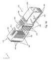
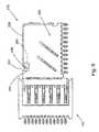
- FIG. 1Cdepicts a right angle receptacle housing that accepts receptacle insert molded leadframe assemblies (IMLA) with six differential signal pairs and related ground contacts per centerline.
- IMLAreceptacle insert molded leadframe assemblies
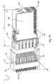
- FIG. 1Ddepicts a vertical header connector with six differential signal pairs and related ground contacts per centerline.
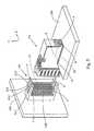
- FIG. 2depicts a vertical header connector and right-angle receptacle connector mounted to respective substrates.
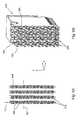
- FIG. 3depicts an orthogonal connector footprint and electrical contacts positioned on the orthogonal footprint.
- FIGS. 4A and 4Bare front and isometric views, respectively, of a right-angle receptacle connector with a receptacle housing.
- FIGS. 5A and 5Bare front and isometric views, respectively, of a right-angle receptacle connector without a receptacle housing.
- FIGS. 6A and 6Bare top and side views, respectively, of a four differential signal pair IMLA for a right-angle receptacle connector.
- FIGS. 7A and 7Bare front and isometric views, respectively, of a receptacle housing.
- FIGS. 8A and 8Bdepict an IMLA being received into a receptacle housing.
- FIG. 9is a side view of the mated electrical connectors depicted in FIGS. 1A and 1B .
- FIGS. 10A and 10Bdepict an array of electrical contacts mating with a first embodiment receptacle IMLA.
- FIGS. 11A and 11Bdepict an array of electrical contacts mating with a second embodiment receptacle IMLA.
- FIGS. 12A and 12Bdepict an array of electrical contacts mating with a third embodiment receptacle IMLA.
- FIGS. 13A and 13Bdepict an array of electrical contacts mating with a fourth embodiment receptacle IMLA.
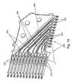
- FIG. 14depicts a mated right angle receptacle IMLA with plastic dielectric material removed.
- FIG. 15is a detailed view of a portion of the right angle receptacle IMLA of FIG. 14 .
- FIG. 16depicts a header IMLA and a right angle receptacle IMLA.
- FIG. 17depicts an array of electrical contacts mating with right angle electrical contacts.
- FIGS. 1A and 1Bdepict a first electrical connector 110 and a second electrical connector 210 .
- the first electrical connector 110may be a vertical header connector. That is, the first electrical connector 110 may define mating and mounting regions that are parallel to one another.
- the second electrical connector 210may be a right-angle connector, or some other suitable mating connector that mates with first electrical connector 110 . That is, the second electrical connector 210 may define mating and mounting regions that are perpendicular to one another.
- first or second electrical connectors 110 , 210could be a vertical connector or a right-angle connector
- first or second electrical connectors 110 , 210could be a header connector or a receptacle connector
- both of the first and second electrical connectors 110 , 210can be mezzanine connectors.
- the first and second electrical connectors 110 and 210may be shieldless high-speed electrical connectors, i.e., connectors that operate without metallic crosstalk plates at data transfer rates at or above four Gigabits/sec, and typically anywhere at or between 6.25 through 12.5 Gigabits/sec or more (about 80 through 35 picosecond rise times) with acceptable worst-case, multi-active crosstalk on a victim pair of no more than six percent. Worst case, multi-active crosstalk may be determined by the sum of the absolute values of six or eight aggressor differential signal pairs ( FIG. 3 ) that are closest to the victim differential signal pair. Rise time ⁇ 0.35/bandwidth, where bandwidth is approximately equal to one-half of the data transfer rate.
- Each differential signal pairmay have a differential impedance of approximately 85 to 100 Ohms, plus or minus 10 percent.
- the differential impedancemay be matched to the impedance of a system, such as a printed circuit board or integrated circuit, for example, to which the connectors may be attached.
- the connectors 110 and 210may have an insertion loss of approximately ⁇ 1 dB or less up to about a five-Gigahertz operating frequency and of approximately ⁇ 2 dB or less up to about a ten-Gigahertz operating frequency.
- the first electrical connector 110may include a header housing 120 that carries electrical contacts 130 .
- the electrical contacts 130include a header mating portion 150 and a header compliant portion 140 .
- Each of the header mating portions 150may define a respective first broadside and a respective second broadside opposite the first broadside.
- Header compliant portions 140may be press-fit tails, surface mount tails, or fusible elements such as solder balls.
- the electrical contacts 130may be insert molded prior to attachment to the header housing 120 or stitched into the header housing 120 .
- Each of the electrical contacts 130may have a material thickness approximately equal to its respective height, although the height may be greater than the material thickness.
- the electrical contacts 130may have a material thickness of about 0.1 mm to 0.45 mm and a contact height of about 0.1 mm to 0.9 mm.
- the adjacent electrical contacts 130 that define a differential signal pairmay be equally spaced or unevenly spaced from an adjacent ground contact.
- the spacing between a first differential signal contact and a second adjacent differential signal contactmay be approximately 1.2 to 4 times less than the spacing between the second differential signal contact and an adjacent ground contact. As shown in FIG.
- a uniform X-direction centerline pitch CL 1 , CL 2 , CL 3 of about 1 mm to 2 mmis desired and an approximate 1 mm to 1.5 mm Y-direction centerline pitch CLA, CLB is desired, with 1.2 mm, 1.3 mm, or 1.4 mm preferred.
- the spacing between adjacent electrical contacts 130may correspond to the dielectric material between the electrical contacts 130 .
- electrical contacts 130may be spaced more closely to one another where the dielectric material is air, than they might be where the dielectric material is a plastic.
- second electrical connector 210includes insert molded leadframe assemblies (IMLA) 220 that are carried by a receptacle housing 240 .
- Each IMLA 220carries electrical contacts, such as right angle electrical contacts 250 .
- Any suitable dielectric material, such as air or plastic,may be used to isolate the right angle electrical contacts 250 from one another.
- the right angle electrical contacts 250include a receptacle mating portion 270 and a receptacle compliant portion 260 .
- the receptacle compliant portions 260may be similar to the header compliant portions 140 and may include press-fit tails, surface mount tails, or fusible elements such as solder balls.
- the right angle electrical contacts 250may have a material thickness of about 0.1 mm to 0.5 mm and a contact height of about 0.1 mm to 0.9 mm.
- the contact heightmay vary over the overall length of the right angle electrical contacts 250 , such that the mating ends 280 of the right angle electrical contacts 250 have a height of about 0.9 mm and an adjacent lead portion 255 ( FIG. 14 ) narrows to a height of about 0.2 mm.
- a ratio of mating end 280 height to lead portion 255 ( FIG. 14 ) heightmay be about five.
- the second electrical connector 210also may include an IMLA organizer 230 that may be electrically insulated or electrically conductive.
- An electrically conductive IMLA organizer 230may be electrically connected to electrically conductive portions of the IMLAs 220 via slits 280 defined in the IMLA organizer 230 or any other suitable connection.
- the first and second electrical connectors 110 , 210 in FIGS. 1A and 1Bmay include four differential signal pairs and interleaved ground contacts positioned edge-to-edge along centerline CL 1 .
- any number of differential signal pairscan extend along centerline CL 1 .
- two, three, four, five, six, or more differential signal pairsare possible, with or without interleaved ground contacts.
- a differential signal pair positioned along a centerline adjacent to centerline CL 1may be offset from a differential signal pair positioned along centerline CL 2 .
- second electrical connector 210has a depth D of less than 46 mm, preferably about 35 mm, when the second electrical connector 210 includes IMLAs 220 having eighteen right angle electrical contacts 250 .
- FIG. 1Cdepicts a receptacle housing 240 A that is configured to receive twelve IMLAs 220 ( FIGS. 6A , 6 B), each having six differential pairs and interleaved ground contacts positioned edge-to-edge along a common respective centerline CL 1 , CL 2 , CL 3 .
- the differential signal pairs and interleaved ground contacts of each IMLAextend along respective centerlines CL 1 , CL 2 , CL 3 , etc. in the Y direction and the centerlines CL 1 , CL 2 , CL 3 are spaced apart in the X direction.
- a receptacle mating regionis defined by all of the receptacle mating portions 270 ( FIG. 1A ) that populate the X by Y area when the IMLAs are attached to the receptacle header 240 A.
- the centerline spacing between differential pairs on centerlines CL 1 , CL 2 , and CL 3may be about 1 mm to 4 mm, with 1.5 mm or 1.8 mm centerline spacing preferred.
- the receptacle mating region of a second electrical connector 210 configured with twelve IMLAs 220 each comprising six differential pairs and interleaved ground contacts positioned edge-to-edgeis approximately 20 mm to 25 mm in length in the X direction by approximately 20 mm to 27 mm in length in the Y direction.
- a 20 mm by 20 mm receptacle mating region in this embodimentincludes approximately two hundred and sixteen individual receptacle mating portions which can be paired into about seventy-two differential signal pairs.
- the number of differential signal pairs per inch of card edgemeasured in the X direction, may be approximately eighty-four to eighty-five (more than eighty-two) when the differential signal pairs are on 1.8 mm centerlines CL 1 , CL 2 , CL 3 and approximately 101 to 102 when the differential signal pairs are on 1.5 mm centerlines CL 1 , CL 2 , CL 3 .
- the height or Y direction length and the depth D( FIG. 1A ) preferably stays constant regardless of the centerline spacing or the total number of IMLAs added or omitted.
- FIG. 1Dshows a first electrical connector 110 A with electrical contacts 130 arranged into six differential signal pairs S+, S ⁇ and interleaved ground contacts G per centerline CL 1 , CL 2 , CL 3 .
- First electrical connector 110 Acan mate with the receptacle housing 240 A shown in FIG. 1C .
- a header mating region the first electrical connector 110is defined by an imaginary square or rectangular perimeter P 1 that intersects electrical contacts 1 , 2 , 3 , 4 and includes the header mating portions 150 circumscribed by imaginary perimeter P 1 .
- four centerlines CL 1 , CL 2 , CL 3 , CL 4 of twelve contactsare shown in FIG. 2 , for a total of four differential signal pairs and four interleaved ground contacts per centerline, the header mating region can be expanded in total area by adding more centerlines of electrical contacts or more electrical contacts 130 in the Y direction.
- the number of differential signal pairs per inch of card edge or X directionis approximately fifty-six at a 1.8 mm centerline spacing and approximately sixty-eight at a 1.5 mm centerline spacing.
- the card pitch between daughter cards stacked in series on a back panel or midplaneis less than 25 mm, and is preferably about 18 mm or less.
- the number of differential signal pairs per inch of card edge Xis approximately seventy-one differential signal pairs at a 1.8 mm centerline spacing and approximately eighty-five pairs at a 1.5 mm centerline spacing.
- the card pitchis less than 25 mm, and is preferably about 21 mm.
- the card pitchis less than 35 mm, and is preferably about 25 mm or less.
- the card pitchincreases by about 3 mm for each differential signal pair and adjacent ground contact added along a respective centerline in the Y direction and decreases by roughly the same amount when a differential signal pair and adjacent ground contact are omitted.
- Differential signal pairs per inch of card edgeincreases by about fourteen to seventeen differential signal pairs for every differential signal pair added to the centerline or omitted from the centerline, assuming the centerline spacing and the number of centerlines remain constant.
- a receptacle footprint of the second electrical connector 210is defined by an imaginary square or rectangular perimeter P 2 that passes through receptacle compliant portion tails 5 , 6 , 7 , and 8 and circumscribes receptacle compliant portions 260 within the P 2 perimeter.
- the receptacle footprint of the second electrical connectoris preferably about 20 mm by 20 mm for a six differential signal pair connector.
- a non-orthogonal header footprint of a mating six pair first electrical connector 110is also preferably about 20 mm by 20 mm.
- the first electrical connector 110may be mounted to a first substrate 105 such as a backplane or midplane.
- the second electrical connector 210may be mounted to a second substrate 205 such as a daughter card.
- FIG. 3is a front view of a connector and corresponding via footprint, such as the first electrical connector 110 A ( FIG. 1D ) mounted onto the first substrate 105 .
- the header housing 120hidden in FIG. 3 for clarity.
- the first electrical connector 110 Aincludes electrical contacts 130 arranged along centerlines, as described above and each header compliant portion 140 may include a respective tail portion 265 .
- the header compliant portions 140 and the corresponding footprint on the first substrate 105are both arranged for shared via orthogonal mounting through the first substrate 105 , such as a backplane or midplane. Tail portions 265 of a differential signal pair 275 and the corresponding substrate via may jog in opposite directions with respect to one another.
- one tail portion and via of the differential signal pair 275may jog in the X direction, and a second tail portion and via of a second contact of the differential signal pair 275 may jog in the X- direction.
- the ground contacts G adjacent to the differential signal pairmay or may not jog with respect to the centerline CL 1 .
- the tail portions 265 of the differential signal pairs 275 positioned along centerline CL 1may have a tail and corresponding via orientation that is reversed from the tail and corresponding via orientation of tail portions 265 of differential signal pairs 285 positioned along an adjacent centerline CL 2 .
- the tail portion 265 and corresponding via of a first contact of a first differential signal pair 275 positioned along first centerline CL 1may jog in the X- direction.
- a tail portion 265 and corresponding via of a corresponding first contact of a second differential signal pair 285 in a second centerline CL 2may jog in the X direction.
- the tail portion 265 and corresponding via of a second contact of the first differential signal pair 275 positioned along the first centerline CL 1may jog in the X direction
- a tail portion 265 and corresponding via of a second contact of the second differential signal pair 285 in the second centerlinemay jog in the X-direction.
- the tail portions 265 and respective vias positioned along a first centerline CL 1may jog in a pattern reverse to the pattern of the tail portions 265 and respective vias of the terminal ends of contacts positioned along centerline CL 2 . This pattern can repeat for the remaining centerlines.
- the substrate via footprint and corresponding first electrical connector 110 A shown in FIG. 3provides for at least six differential signal pairs 275 , 285 positioned along each of the eleven centerlines CL 1 , CL 2 , CL 3 , etc.
- Each of the centerlinesadditionally may include respective ground contacts/vias G disposed between signal pairs of the centerline.
- the substratemay define a centerline pitch Pc between adjacent centerlines CL 1 , CL 2 .
- the centerline pitch Pc of the substratemay be one and a half times the via or electrical contact 130 spacing within a respective centerline, for example.
- the first electrical connector 110 and viaspreferably have a square or rectangular footprint defined by an imaginary perimeter P 3 that passes through 1 A, 1 B, 1 C, 1 D and circumscribes the header compliant portions 140 or interior vias.
- Differential signal pairs Acan be possible aggressor pairs and differential signal pair V can be a possible victim differential signal pair.
- FIGS. 4A and 4Bare front views of the second electrical connector 210 shown in FIGS. 1A and 1B .
- FIGS. 5A and 5Bare front and isometric views, respectively, of the second electrical connector 210 shown in FIGS. 1A and 1B without the receptacle housing 240 .
- the receptacle mating portions 270 of the right angle electrical contacts 250may define lead portions 290 and mating ends 280 .
- the mating ends 280may be offset from the centerline CL 1 to fully accept respective header mating portions 150 of electrical contacts 130 . That is, each mating end 280 may be offset in a direction that is perpendicular to the direction along which the centerline CL 1 extends. Alternate mating ends 280 may be offset in alternating directions.
- mating end 280 of a first one of the right angle electrical contacts 250may be offset from centerline CL 1 in a first direction that is perpendicular to centerline CL 1
- the mating end 280 of an adjacent right angle electrical contact 250 positioned along the same centerline CL 1may be offset from the centerline CL 1 in a second direction that is opposite the first direction.
- the mating ends 280may bend toward the centerline CL 1 .
- the mating ends 280 of the right angle electrical contacts 250may be adapted to engage blade-shaped header mating portions 150 ( FIG. 1 ) of the first electrical contacts 130 from the first electrical connector 110 , which, as described above, may be aligned along a centerline coincident with the centerline CL 1 shown in FIG. 5A .
- FIGS. 6A and 6Bare top and side views, respectively, of an IMLA 220 .
- each leadframe contact 250may define a lead portion 255 ( FIG. 14 ) that extends between the receptacle mating portion 270 and the receptacle compliant portions 260 .
- the right angle electrical contacts 250may define one or more angles. Ideally, lengths of the right angle electrical contacts 250 that form a differential signal pair 295 should vary by about 2 mm or less so that the signal skew is less than 10 picoseconds.
- IMLAs 220may also include a respective tab 330 that may be defined in a recess 340 in plastic dielectric material 301 or otherwise exposed.
- the dielectric material 310may have a respective top surface 350 thereof.
- the recess 340may be defined in the top surface 350 of the dielectric material 310 such that the tab 330 is exposed in the recess 340 .
- the dielectric material 310may include one or more protrusions 320 .
- Each protrusion 320may be an optional keying feature that extends from the dielectric material 310 in a direction in which the IMLA 220 is received into a cavity 380 ( FIG. 7B ) the receptacle housing 240 ( FIG. 7B ).
- the IMLA 220could have cavities that accept protrusions similar to protrusions 320 that extend from the receptacle housing 240 to minimize relative motion perpendicular to the mating direction.
- FIGS. 7A and 7Bare front and isometric views, respectively, of the receptacle housing 240 .
- the receptacle housing 240may define one or more mating windows 360 , one or more mating cavities 370 , and one or more cavities 380 .
- the receptacle housing 240may further include walls 390 that separate adjacent right angle electrical contacts 250 ( FIG. 1A ) along a centerline to prevent electrical shorting.
- Each of the mating windows 360may receive, as shown in FIG. 8A , a blade-shaped header mating portion 150 of a corresponding first electrical contact 130 from the first electrical connector 110 when the first electrical connector 110 and the second electrical connector 210 are mated.
- a receptacle mating portion 270 of a corresponding right angle electrical contact 250 from the second electrical connector 210may extend into each of the mating cavities 370 and may pre-load the offset mating ends 280 .
- the mating cavities 370may be offset from one another to accommodate the offset mating ends 280 of right angle electrical contacts 250 .
- Each of the cavities 380may receive a respective protrusion 320 ( FIG. 6B ).
- the receptacle housing 240may include latches 400 to secure the IMLAs 220 , shown in FIGS. 6A and 6B , into the receptacle housing 240 .
- a plurality of IMLAs 220may be arranged in the receptacle housing 240 such that each of the IMLAs 220 is adjacent to another IMLA 220 on at least one side.
- the mating portions 270 of the right angle electrical contacts 250may be received into the mating cavities 370 .
- the IMLAs 220may be received into the mating cavities 370 until each of the respective protrusions 320 is inserted into a corresponding cavity 380 .
- the IMLA organizer 230( FIG. 9 ) may then be assembled to the IMLAs 220 to complete the assembly of the second electrical connector 210 .
- FIG. 9is a side view of the mated electrical first and second electrical connectors 110 , 210 shown in FIGS. 1A and 1B .
- each of the respective slots 280that may be defined in a curved portion 410 of the IMLA organizer 230 may receive a respective tab 330 from the recess 340 in IMLAs 220 .
- each of the tabs 330may define a first side and a second side opposite of the first side.
- FIGS. 10A-15Bdepict an array of first electrical contacts 130 mating and receptacle mating portions 270 of right angle electrical contacts 250 .
- Each of the blade-shaped header mating portions 150 of the first electrical contacts 130 from the first electrical connector 110 ( FIG. 1A )may mate with a corresponding mating end 280 of a right angle electrical contact 250 IMLA 220 from the second electrical connector 210 ( FIG. 1A ).
- Each of the mating ends 280may contact a respective header mating portion 150 in at least one place, and preferably at least two places.
- the first broadsides of the blade-shaped header mounting portions 150 of the first electrical contacts 130may define a first plane in a centerline direction CLD.
- the second broadsides of the blade-shaped header mounting portions 150 of the first electrical contacts 130may define a second plane that may be offset from and parallel to the first plane.
- Some of the mating ends 280 of the receptacle mating portions 270may physically contact the first broadside of a corresponding blade-shaped header mating portion 150 , but not second broadside of the same blade-shaped header mating portion 150 .
- the other mating ends 280may physically contact the second broadside of a corresponding header mating portion 150 , but not the first opposed broadside.
- FIGS. 11A and 11Bare similar to FIGS. 10A and 10B .
- the IMLA 220 Acarries right angle electrical contacts 250 .
- two adjacent mating ends 280contact a respective first broadside of two adjacent header mating portions 150 and two other adjacent mating ends 280 contact a respective second broadside of two other adjacent header mating portions 150 .
- FIGS. 12A and 12Bare similar to FIGS. 10A and 10B .
- the IMLA 220 Bcarries right angle electrical contacts 250 .
- three adjacent mating ends 280contact a respective first broadside of three adjacent header mating portions 150 and three other adjacent mating ends 280 contact a respective second broadside of three other adjacent header mating portions 150 .
- FIGS. 13A and 13Bare similar to FIGS. 10A and 10B .
- the IMLA 220 Ccarries right angle electrical contacts 250 .
- four adjacent mating ends 280contact a respective first broadside of four adjacent header mating portions 150 and four other adjacent mating ends 280 contact a respective second broadside of four other adjacent header mating portions 150 .
- FIGS. 10A through 13B embodimentsshow adjacent mating ends 280 physically contacting opposite broadsides of corresponding header mating portions 150 the header mating portions 150 .
- FIG. 14shows a plurality of right angle electrical contacts 250 with plastic dielectric material removed for clarity.
- the right angle electrical contacts 250may include a plurality of differential signal pairs 420 and one or more electrically-conductive ground contacts 450 .
- Each right angle electrical contact 250may define a lead portion 255 that extends between the receptacle mating portion 270 and the receptacle compliant portion 260 .
- the lead portions 255may define one or more angles.
- Each lead portion 255may have a respective length, L-r.
- the right angle electrical contacts 250may have different lengths, as shown, which may result in signal skew. Ideally, the lengths L-r of right angle electrical contacts 250 that form a differential signal pair 420 should vary by about 1 mm or less so that the signal skew is less than 10 picoseconds.
- FIG. 15is a detailed view of the differential signal pair 420 and a ground contact 450 shown in FIG. 14 .
- each of the differential signal pairs 420may include a first signal contact 430 and a second signal contact 440 .
- the first and second signal contacts 430 , 440may be spaced apart by a distance Dl such that the first and second signal contacts 430 , 440 are tightly electrically coupled to one another.
- the gap between the first signal contact 430 and the second signal contact 440in plastic, may be about 0.2 to 0.8 mm depending on the height and material thickness of the contacts. A gap of about 0.25 mm to 0.4 mm is preferred. In air, the gap may be less.
- the adjacent ground contact 450may be spaced apart by a distance D 2 from the differential signal pair within the IMLA 220 .
- the distance D 2may be approximately 1.5 to 4 times the distance D 1 .
- the D 2 distance between the second signal contact 440 and the ground contact 450may be approximately 0.3 to 0.8 mm in plastic.
- a D 2 distance of about 0.4 mmis preferred. In air, the values may be smaller.
- the height or width of the first signal contact 430 and the second signal contact 440may be approximately equal to the material thickness, although it may be greater than a material thickness. For example, the height may vary between about 0.1 mm to 0.9 mm.
- the ground contact 450may be similar in dimensions to the first and second signal contacts 430 , 440 to optimize spacing between signals contacts and grounds to produce an electrical connector with a differential signal pair density greater than eighty-two differential signal pairs per inch of card edge, and a stacked card pitch distance of less than about 35 mm or 31 mm (about 25 mm preferred), and a back panel to rear connector length of less than about 37 mm (about 35 mm preferred).
- a second electrical connector with right angle electrical contacts and more than eighty-two differential pairs per inch of card edge and the associated interleaved ground contacts 450rises less than 20 mm from a daughter card mounting surface and only occupies about 400 square millimeters of daughter card surface area.
- FIG. 16shows that the electrical contacts 130 of the first electrical connector 110 may have an insert molded housing 480 adjacent to the header mating portions 150 .
- the insert molded housing 480may hold electrical contacts 130 of differing electrical and physical lengths.
- FIG. 17depicts the array of electrical contacts 130 and the IMLA 220 in FIG. 16 without the insert molded housing 480 .
- the electrical contacts 130may define a respective header lead portions 135 between each of the header compliant portions 140 and each of the header mating portions 150 .
- the header lead portions 135 of adjacent contactsmay vary in length.
- a first electrical contact 470may have a header lead portion 135 with a first physical and electrical length L 1 and a second electrical contact 480 adjacent to the first electrical contact 470 may have a header lead portion 135 of a second physical and electrical length L 2 .
- the first length L 1may be less than the second length L 2 to correct for skew in third and fourth electrical contacts 490 and 500 .
- third electrical contact 490may have a third physical and electrical length L 3 and a fourth electrical contact 500 adjacent to the third electrical contact 490 may have a fourth physical and electrical length.
- the fourth physical and electrical lengthmay be less than the third length.
- the third electrical contact 490may be mated to the first electrical contact 470 and the fourth electrical contact 500 may be mated with the second electrical contact 480 such that the summation of the first physical and electrical length and the third physical and electrical length may be approximately equal to the summation of the second physical and electrical length and the fourth physical and electrical length. That is, the total electrical length between two contacts in a differential signal pair may be corrected for skew.
Landscapes
- Details Of Connecting Devices For Male And Female Coupling (AREA)
- Coupling Device And Connection With Printed Circuit (AREA)
Abstract
Description
Claims (18)
Priority Applications (3)
| Application Number | Priority Date | Filing Date | Title |
|---|---|---|---|
| US12/843,735US8096832B2 (en) | 2006-12-19 | 2010-07-26 | Shieldless, high-speed, low-cross-talk electrical connector |
| US13/310,970US8382521B2 (en) | 2006-12-19 | 2011-12-05 | Shieldless, high-speed, low-cross-talk electrical connector |
| US13/770,425US8678860B2 (en) | 2006-12-19 | 2013-02-19 | Shieldless, high-speed, low-cross-talk electrical connector |
Applications Claiming Priority (9)
| Application Number | Priority Date | Filing Date | Title |
|---|---|---|---|
| US87079106P | 2006-12-19 | 2006-12-19 | |
| US87079306P | 2006-12-19 | 2006-12-19 | |
| US87079606P | 2006-12-19 | 2006-12-19 | |
| US88708107P | 2007-01-29 | 2007-01-29 | |
| US11/726,936US7503804B2 (en) | 2006-12-19 | 2007-03-23 | Backplane connector |
| US91749107P | 2007-05-11 | 2007-05-11 | |
| US11/958,098US7497736B2 (en) | 2006-12-19 | 2007-12-17 | Shieldless, high-speed, low-cross-talk electrical connector |
| US12/396,086US7762843B2 (en) | 2006-12-19 | 2009-03-02 | Shieldless, high-speed, low-cross-talk electrical connector |
| US12/843,735US8096832B2 (en) | 2006-12-19 | 2010-07-26 | Shieldless, high-speed, low-cross-talk electrical connector |
Related Parent Applications (1)
| Application Number | Title | Priority Date | Filing Date |
|---|---|---|---|
| US12/396,086ContinuationUS7762843B2 (en) | 2006-12-19 | 2009-03-02 | Shieldless, high-speed, low-cross-talk electrical connector |
Related Child Applications (1)
| Application Number | Title | Priority Date | Filing Date |
|---|---|---|---|
| US13/310,970ContinuationUS8382521B2 (en) | 2006-12-19 | 2011-12-05 | Shieldless, high-speed, low-cross-talk electrical connector |
Publications (2)
| Publication Number | Publication Date |
|---|---|
| US20100291806A1 US20100291806A1 (en) | 2010-11-18 |
| US8096832B2true US8096832B2 (en) | 2012-01-17 |
Family
ID=39588938
Family Applications (5)
| Application Number | Title | Priority Date | Filing Date |
|---|---|---|---|
| US11/958,098ActiveUS7497736B2 (en) | 2006-12-19 | 2007-12-17 | Shieldless, high-speed, low-cross-talk electrical connector |
| US12/396,086ActiveUS7762843B2 (en) | 2006-12-19 | 2009-03-02 | Shieldless, high-speed, low-cross-talk electrical connector |
| US12/843,735ActiveUS8096832B2 (en) | 2006-12-19 | 2010-07-26 | Shieldless, high-speed, low-cross-talk electrical connector |
| US13/310,970ActiveUS8382521B2 (en) | 2006-12-19 | 2011-12-05 | Shieldless, high-speed, low-cross-talk electrical connector |
| US13/770,425ActiveUS8678860B2 (en) | 2006-12-19 | 2013-02-19 | Shieldless, high-speed, low-cross-talk electrical connector |
Family Applications Before (2)
| Application Number | Title | Priority Date | Filing Date |
|---|---|---|---|
| US11/958,098ActiveUS7497736B2 (en) | 2006-12-19 | 2007-12-17 | Shieldless, high-speed, low-cross-talk electrical connector |
| US12/396,086ActiveUS7762843B2 (en) | 2006-12-19 | 2009-03-02 | Shieldless, high-speed, low-cross-talk electrical connector |
Family Applications After (2)
| Application Number | Title | Priority Date | Filing Date |
|---|---|---|---|
| US13/310,970ActiveUS8382521B2 (en) | 2006-12-19 | 2011-12-05 | Shieldless, high-speed, low-cross-talk electrical connector |
| US13/770,425ActiveUS8678860B2 (en) | 2006-12-19 | 2013-02-19 | Shieldless, high-speed, low-cross-talk electrical connector |
Country Status (4)
| Country | Link |
|---|---|
| US (5) | US7497736B2 (en) |
| EP (1) | EP2122789B1 (en) |
| CN (2) | CN102856692B (en) |
| WO (1) | WO2008082548A1 (en) |
Cited By (6)
| Publication number | Priority date | Publication date | Assignee | Title |
|---|---|---|---|---|
| US20110269346A1 (en)* | 2008-11-14 | 2011-11-03 | Molex Incorporated | Resonance modifying connector |
| US20130040500A1 (en)* | 2011-08-12 | 2013-02-14 | Fci Americas Technology Llc | Power connector |
| US8382521B2 (en) | 2006-12-19 | 2013-02-26 | Fci Americas Technology Llc | Shieldless, high-speed, low-cross-talk electrical connector |
| US8540525B2 (en) | 2008-12-12 | 2013-09-24 | Molex Incorporated | Resonance modifying connector |
| US8827750B2 (en)* | 2012-11-06 | 2014-09-09 | Kuang Ying Computer Equipment Co., Ltd. | Application structure for electric wave effect of transmission conductor |
| US20190036251A1 (en)* | 2017-07-31 | 2019-01-31 | Fci Usa Llc | Electrical contact pre-load structure |
Families Citing this family (116)
| Publication number | Priority date | Publication date | Assignee | Title |
|---|---|---|---|---|
| US20080214059A1 (en)* | 2007-03-02 | 2008-09-04 | Tyco Electronics Corporation | Orthogonal electrical connector with increased contact density |
| US7566247B2 (en)* | 2007-06-25 | 2009-07-28 | Tyco Electronics Corporation | Skew controlled leadframe for a contact module assembly |
| US7811100B2 (en)* | 2007-07-13 | 2010-10-12 | Fci Americas Technology, Inc. | Electrical connector system having a continuous ground at the mating interface thereof |
| ATE497270T1 (en)* | 2007-10-04 | 2011-02-15 | 3M Innovative Properties Co | CONNECTORS IN THE FIELD OF TELECOMMUNICATIONS |
| EP2240980A2 (en) | 2008-01-17 | 2010-10-20 | Amphenol Corporation | Electrical connector assembly |
| US8764464B2 (en) | 2008-02-29 | 2014-07-01 | Fci Americas Technology Llc | Cross talk reduction for high speed electrical connectors |
| US7780462B2 (en)* | 2008-10-17 | 2010-08-24 | Tyco Electronics Corporation | Electrostatic discharge contact |
| US7988456B2 (en)* | 2009-01-14 | 2011-08-02 | Tyco Electronics Corporation | Orthogonal connector system |
| US8172614B2 (en) | 2009-02-04 | 2012-05-08 | Amphenol Corporation | Differential electrical connector with improved skew control |
| US9277649B2 (en) | 2009-02-26 | 2016-03-01 | Fci Americas Technology Llc | Cross talk reduction for high-speed electrical connectors |
| US8366485B2 (en) | 2009-03-19 | 2013-02-05 | Fci Americas Technology Llc | Electrical connector having ribbed ground plate |
| US8231415B2 (en)* | 2009-07-10 | 2012-07-31 | Fci Americas Technology Llc | High speed backplane connector with impedance modification and skew correction |
| US7883367B1 (en)* | 2009-07-23 | 2011-02-08 | Hon Hai Precision Ind. Co., Ltd. | High density backplane connector having improved terminal arrangement |
| GB0914025D0 (en) | 2009-08-11 | 2009-09-16 | 3M Innovative Properties Co | Telecommunications connector |
| US8267721B2 (en) | 2009-10-28 | 2012-09-18 | Fci Americas Technology Llc | Electrical connector having ground plates and ground coupling bar |
| US8616919B2 (en) | 2009-11-13 | 2013-12-31 | Fci Americas Technology Llc | Attachment system for electrical connector |
| JP4905542B2 (en)* | 2009-11-30 | 2012-03-28 | 日立電線株式会社 | connector |
| US8313344B2 (en)* | 2009-12-30 | 2012-11-20 | Fci Americas Technology Llc | Eye-of-the-needle mounting terminal |
| US20110159710A1 (en)* | 2009-12-31 | 2011-06-30 | Crighton Alan D | Array of electrical connectors having offset electrical connectors |
| US20110159473A1 (en)* | 2009-12-31 | 2011-06-30 | Crighton Alan D | Array of electrical connectors having offset electrical connectors |
| JP5293628B2 (en)* | 2010-02-01 | 2013-09-18 | 日立電線株式会社 | connector |
| US20110256763A1 (en)* | 2010-04-07 | 2011-10-20 | Jan De Geest | Mitigation of crosstalk resonances in interconnects |
| CN107069274B (en) | 2010-05-07 | 2020-08-18 | 安费诺有限公司 | High performance cable connector |
| CN102290649B (en)* | 2010-06-15 | 2015-05-06 | 富士康(昆山)电脑接插件有限公司 | Electric connector |
| US8734187B2 (en)* | 2010-06-28 | 2014-05-27 | Fci | Electrical connector with ground plates |
| US9136634B2 (en) | 2010-09-03 | 2015-09-15 | Fci Americas Technology Llc | Low-cross-talk electrical connector |
| US8750176B2 (en) | 2010-12-22 | 2014-06-10 | Apple Inc. | Methods and apparatus for the intelligent association of control symbols |
| US8888529B2 (en) | 2011-02-18 | 2014-11-18 | Fci Americas Technology Llc | Electrical connector having common ground shield |
| SG185162A1 (en)* | 2011-04-28 | 2012-11-29 | 3M Innovative Properties Co | An electrical connector |
| US8657616B2 (en) | 2011-05-24 | 2014-02-25 | Fci Americas Technology Llc | Electrical contact normal force increase |
| US8920194B2 (en)* | 2011-07-01 | 2014-12-30 | Fci Americas Technology Inc. | Connection footprint for electrical connector with printed wiring board |
| WO2013007774A1 (en)* | 2011-07-13 | 2013-01-17 | Fci | Assembly and board mounting connector |
| JP5904573B2 (en)* | 2011-08-19 | 2016-04-13 | 富士通コンポーネント株式会社 | connector |
| US9022812B2 (en)* | 2011-11-02 | 2015-05-05 | Fci Americas Technology Llc | Electrical connector with reduced normal force |
| US9545040B2 (en) | 2012-01-23 | 2017-01-10 | Fci Americas Technology Llc | Cable retention housing |
| US9838226B2 (en) | 2012-01-27 | 2017-12-05 | Apple Inc. | Methods and apparatus for the intelligent scrambling of control symbols |
| US8897398B2 (en) | 2012-01-27 | 2014-11-25 | Apple Inc. | Methods and apparatus for error rate estimation |
| EP2624034A1 (en) | 2012-01-31 | 2013-08-07 | Fci | Dismountable optical coupling device |
| USD727268S1 (en) | 2012-04-13 | 2015-04-21 | Fci Americas Technology Llc | Vertical electrical connector |
| USD718253S1 (en) | 2012-04-13 | 2014-11-25 | Fci Americas Technology Llc | Electrical cable connector |
| US9231393B2 (en) | 2012-04-13 | 2016-01-05 | Fci Americas Technology Llc | Electrical assembly with organizer |
| USD727852S1 (en) | 2012-04-13 | 2015-04-28 | Fci Americas Technology Llc | Ground shield for a right angle electrical connector |
| US8944831B2 (en) | 2012-04-13 | 2015-02-03 | Fci Americas Technology Llc | Electrical connector having ribbed ground plate with engagement members |
| US9257778B2 (en) | 2012-04-13 | 2016-02-09 | Fci Americas Technology | High speed electrical connector |
| US9543703B2 (en) | 2012-07-11 | 2017-01-10 | Fci Americas Technology Llc | Electrical connector with reduced stack height |
| USD751507S1 (en) | 2012-07-11 | 2016-03-15 | Fci Americas Technology Llc | Electrical connector |
| US9240644B2 (en) | 2012-08-22 | 2016-01-19 | Amphenol Corporation | High-frequency electrical connector |
| USD745852S1 (en) | 2013-01-25 | 2015-12-22 | Fci Americas Technology Llc | Electrical connector |
| US9450790B2 (en) | 2013-01-31 | 2016-09-20 | Apple Inc. | Methods and apparatus for enabling and disabling scrambling of control symbols |
| USD720698S1 (en) | 2013-03-15 | 2015-01-06 | Fci Americas Technology Llc | Electrical cable connector |
| US8917194B2 (en)* | 2013-03-15 | 2014-12-23 | Apple, Inc. | Methods and apparatus for context based line coding |
| US9210010B2 (en) | 2013-03-15 | 2015-12-08 | Apple, Inc. | Methods and apparatus for scrambling symbols over multi-lane serial interfaces |
| CN104466492B (en)* | 2013-09-17 | 2016-11-16 | 通普康电子(昆山)有限公司 | Communications connector and terminal-framework thereof |
| DE102013221722B4 (en)* | 2013-10-25 | 2020-02-13 | All Best Precision Technology Co., Ltd. | Clamping bracket and higher-level connector |
| CN115411547A (en)* | 2014-01-22 | 2022-11-29 | 安费诺有限公司 | Electrical connector, subassembly, module, cable assembly, electrical assembly and circuit board |
| US9426931B2 (en) | 2014-02-07 | 2016-08-23 | Lockheed Martin Corporation | Fluid-flow-through cooling of circuit boards |
| US9685736B2 (en) | 2014-11-12 | 2017-06-20 | Amphenol Corporation | Very high speed, high density electrical interconnection system with impedance control in mating region |
| US9807869B2 (en) | 2014-11-21 | 2017-10-31 | Amphenol Corporation | Mating backplane for high speed, high density electrical connector |
| US9583851B2 (en)* | 2015-06-11 | 2017-02-28 | Lenovo Enterprise Solutions (Singapore) Pte. Ltd. | Orthogonal card edge connector |
| CN108701922B (en) | 2015-07-07 | 2020-02-14 | Afci亚洲私人有限公司 | Electrical connector |
| TWI754439B (en) | 2015-07-23 | 2022-02-01 | 美商安芬諾Tcs公司 | Connector, method of manufacturing connector, extender module for connector, and electric system |
| US9666962B1 (en)* | 2015-12-17 | 2017-05-30 | Te Connectivity Corporation | Power terminal with compliant pin for electrical power connector |
| WO2017201170A1 (en) | 2016-05-18 | 2017-11-23 | Amphenol Corporation | Controlled impedance edged coupled connectors |
| TWI746561B (en) | 2016-05-31 | 2021-11-21 | 美商安芬諾股份有限公司 | High performance cable termination |
| CN109314334B (en) | 2016-06-15 | 2021-08-20 | 申泰公司 | Overmolded leadframe with contact support and impedance matching features |
| CN106252968B (en)* | 2016-07-29 | 2019-06-07 | 中航光电科技股份有限公司 | Electric connector |
| CN112151987B (en) | 2016-08-23 | 2022-12-30 | 安费诺有限公司 | Configurable high performance connector |
| CN110088985B (en) | 2016-10-19 | 2022-07-05 | 安费诺有限公司 | Flexible shield for ultra-high speed high density electrical interconnects |
| US9923309B1 (en)* | 2017-01-27 | 2018-03-20 | Te Connectivity Corporation | PCB connector footprint |
| TWI788394B (en) | 2017-08-03 | 2023-01-01 | 美商安芬諾股份有限公司 | Cable assembly and method of manufacturing the same |
| CN114512840B (en) | 2017-10-30 | 2024-06-25 | 安费诺富加宜(亚洲)私人有限公司 | Low crosstalk card edge connector |
| US10559929B2 (en)* | 2018-01-25 | 2020-02-11 | Te Connectivity Corporation | Electrical connector system having a PCB connector footprint |
| US10665973B2 (en) | 2018-03-22 | 2020-05-26 | Amphenol Corporation | High density electrical connector |
| WO2019183065A1 (en) | 2018-03-23 | 2019-09-26 | Amphenol Corporation | Insulative support for very high speed electrical interconnection |
| WO2019195319A1 (en) | 2018-04-02 | 2019-10-10 | Ardent Concepts, Inc. | Controlled-impedance compliant cable termination |
| CN108832339B (en)* | 2018-05-31 | 2019-10-01 | 番禺得意精密电子工业有限公司 | Electric connector |
| KR102678838B1 (en) | 2018-07-06 | 2024-06-27 | 샘텍, 인코포레이티드 | Connector with top- and bottom-stitched contacts |
| CN208862209U (en) | 2018-09-26 | 2019-05-14 | 安费诺东亚电子科技(深圳)有限公司 | A connector and its applied PCB board |
| CN113169484A (en) | 2018-10-09 | 2021-07-23 | 安费诺商用电子产品(成都)有限公司 | High density edge connector |
| USD950498S1 (en) | 2018-11-05 | 2022-05-03 | Samtec, Inc. | Connector |
| TWM576774U (en) | 2018-11-15 | 2019-04-11 | 香港商安費諾(東亞)有限公司 | Metal case with anti-displacement structure and connector thereof |
| US10931062B2 (en) | 2018-11-21 | 2021-02-23 | Amphenol Corporation | High-frequency electrical connector |
| USD950499S1 (en) | 2018-12-17 | 2022-05-03 | Samtec, Inc | Connector |
| USD950500S1 (en) | 2018-12-17 | 2022-05-03 | Samtec, Inc. | Connector |
| US11381015B2 (en) | 2018-12-21 | 2022-07-05 | Amphenol East Asia Ltd. | Robust, miniaturized card edge connector |
| WO2020154507A1 (en) | 2019-01-25 | 2020-07-30 | Fci Usa Llc | I/o connector configured for cable connection to a midboard |
| US11101611B2 (en) | 2019-01-25 | 2021-08-24 | Fci Usa Llc | I/O connector configured for cabled connection to the midboard |
| CN111585098B (en) | 2019-02-19 | 2025-08-19 | 安费诺有限公司 | High-speed connector |
| WO2020172395A1 (en) | 2019-02-22 | 2020-08-27 | Amphenol Corporation | High performance cable connector assembly |
| TWM582251U (en) | 2019-04-22 | 2019-08-11 | 香港商安費諾(東亞)有限公司 | Connector set with hidden locking mechanism and socket connector thereof |
| TW202448032A (en) | 2019-05-20 | 2024-12-01 | 美商安芬諾股份有限公司 | Connector module, connector, electronic assembly, electrical connector and wafer of connector module |
| CN114788097A (en) | 2019-09-19 | 2022-07-22 | 安费诺有限公司 | High speed electronic system with midplane cable connector |
| CN110808499B (en)* | 2019-10-12 | 2022-04-05 | 华为机器有限公司 | Male end connector, female end connector, connector assembly and communication equipment |
| USD951875S1 (en) | 2019-10-15 | 2022-05-17 | Samtec, Inc. | Connector |
| US11799230B2 (en) | 2019-11-06 | 2023-10-24 | Amphenol East Asia Ltd. | High-frequency electrical connector with in interlocking segments |
| US11588277B2 (en) | 2019-11-06 | 2023-02-21 | Amphenol East Asia Ltd. | High-frequency electrical connector with lossy member |
| USD949798S1 (en) | 2019-12-06 | 2022-04-26 | Samtec, Inc. | Connector |
| USD951202S1 (en) | 2019-12-06 | 2022-05-10 | Samtec, Inc. | Connector |
| WO2021113148A1 (en)* | 2019-12-06 | 2021-06-10 | Samtec, Inc. | Connector with top-and bottom-stitched contacts |
| WO2021154813A1 (en) | 2020-01-27 | 2021-08-05 | Amphenol Corporation | Electrical connector with high speed mounting interface |
| WO2021154702A1 (en) | 2020-01-27 | 2021-08-05 | Fci Usa Llc | High speed connector |
| TWI887339B (en) | 2020-01-27 | 2025-06-21 | 美商Fci美國有限責任公司 | High speed, high density direct mate orthogonal connector |
| CN113258325A (en) | 2020-01-28 | 2021-08-13 | 富加宜(美国)有限责任公司 | High-frequency middle plate connector |
| CN111448716B (en)* | 2020-03-05 | 2021-09-21 | 四川华丰科技股份有限公司 | Back panel connector |
| US11652307B2 (en) | 2020-08-20 | 2023-05-16 | Amphenol East Asia Electronic Technology (Shenzhen) Co., Ltd. | High speed connector |
| CN212874843U (en) | 2020-08-31 | 2021-04-02 | 安费诺商用电子产品(成都)有限公司 | Electrical connector |
| CN215816516U (en) | 2020-09-22 | 2022-02-11 | 安费诺商用电子产品(成都)有限公司 | Electrical connector |
| CN213636403U (en) | 2020-09-25 | 2021-07-06 | 安费诺商用电子产品(成都)有限公司 | Electrical connector |
| USD958092S1 (en) | 2020-11-20 | 2022-07-19 | Samtec, Inc. | Contact |
| CN114678709B (en)* | 2020-12-24 | 2025-07-25 | 山一电机株式会社 | Connector and connector kit |
| US12176650B2 (en) | 2021-05-05 | 2024-12-24 | Amphenol East Asia Limited (Hong Kong) | Electrical connector with guiding structure and mating groove and method of connecting electrical connector |
| CN215266741U (en) | 2021-08-13 | 2021-12-21 | 安费诺商用电子产品(成都)有限公司 | High-performance card connector meeting high-bandwidth transmission |
| USD1002553S1 (en) | 2021-11-03 | 2023-10-24 | Amphenol Corporation | Gasket for connector |
| USD1067191S1 (en) | 2021-12-14 | 2025-03-18 | Amphenol Corporation | Electrical connector |
| USD1068685S1 (en) | 2021-12-14 | 2025-04-01 | Amphenol Corporation | Electrical connector |
| WO2024050137A1 (en)* | 2022-09-02 | 2024-03-07 | Samtec, Inc. | Electrical connector apparatus and method |
Citations (294)
| Publication number | Priority date | Publication date | Assignee | Title |
|---|---|---|---|---|
| US2664552A (en) | 1950-06-19 | 1953-12-29 | Ericsson Telefon Ab L M | Device for connection of cables by means of plugs and sockets |
| US2849700A (en) | 1956-06-22 | 1958-08-26 | Gen Telephone Company Of Calif | Telephone intercept bridge |
| US2858372A (en) | 1954-08-19 | 1958-10-28 | John M Kaufman | Interception block for telephone exchanges |
| US3115379A (en) | 1961-11-29 | 1963-12-24 | United Carr Fastener Corp | Electrical connector |
| US3286220A (en) | 1964-06-10 | 1966-11-15 | Amp Inc | Electrical connector means |
| US3343120A (en) | 1965-04-01 | 1967-09-19 | Wesley W Whiting | Electrical connector clip |
| US3482201A (en) | 1967-08-29 | 1969-12-02 | Thomas & Betts Corp | Controlled impedance connector |
| US3538486A (en) | 1967-05-25 | 1970-11-03 | Amp Inc | Connector device with clamping contact means |
| US3591834A (en) | 1969-12-22 | 1971-07-06 | Ibm | Circuit board connecting means |
| US3641475A (en) | 1969-12-18 | 1972-02-08 | Bell Telephone Labor Inc | Intercept connector for making alternative bridging connections having improved contact clip construction |
| US3663925A (en) | 1970-05-20 | 1972-05-16 | Us Navy | Electrical connector |
| US3669054A (en) | 1970-03-23 | 1972-06-13 | Amp Inc | Method of manufacturing electrical terminals |
| US3701076A (en) | 1969-12-18 | 1972-10-24 | Bell Telephone Labor Inc | Intercept connector having two diode mounting holes separated by a diode supporting recess |
| US3748633A (en) | 1972-01-24 | 1973-07-24 | Amp Inc | Square post connector |
| US3827005A (en) | 1973-05-09 | 1974-07-30 | Du Pont | Electrical connector |
| US3867008A (en) | 1972-08-25 | 1975-02-18 | Hubbell Inc Harvey | Contact spring |
| US4030792A (en) | 1976-03-01 | 1977-06-21 | Fabri-Tek Incorporated | Tuning fork connector |
| US4076362A (en) | 1976-02-20 | 1978-02-28 | Japan Aviation Electronics Industry Ltd. | Contact driver |
| US4159861A (en) | 1977-12-30 | 1979-07-03 | International Telephone And Telegraph Corporation | Zero insertion force connector |
| US4232924A (en) | 1978-10-23 | 1980-11-11 | Nanodata Corporation | Circuit card adapter |
| US4260212A (en) | 1979-03-20 | 1981-04-07 | Amp Incorporated | Method of producing insulated terminals |
| US4288139A (en) | 1979-03-06 | 1981-09-08 | Amp Incorporated | Trifurcated card edge terminal |
| US4383724A (en) | 1980-06-03 | 1983-05-17 | E. I. Du Pont De Nemours And Company | Bridge connector for electrically connecting two pins |
| US4402563A (en) | 1981-05-26 | 1983-09-06 | Aries Electronics, Inc. | Zero insertion force connector |
| US4482937A (en) | 1982-09-30 | 1984-11-13 | Control Data Corporation | Board to board interconnect structure |
| US4523296A (en) | 1983-01-03 | 1985-06-11 | Westinghouse Electric Corp. | Replaceable intermediate socket and plug connector for a solid-state data transfer system |
| US4560222A (en) | 1984-05-17 | 1985-12-24 | Molex Incorporated | Drawer connector |
| US4664456A (en) | 1985-07-30 | 1987-05-12 | Amp Incorporated | High durability drawer connector |
| US4664458A (en) | 1985-09-19 | 1987-05-12 | C W Industries | Printed circuit board connector |
| US4717360A (en) | 1986-03-17 | 1988-01-05 | Zenith Electronics Corporation | Modular electrical connector |
| EP0273683A2 (en) | 1986-12-26 | 1988-07-06 | Fujitsu Limited | An electrical connector |
| US4762500A (en) | 1986-12-04 | 1988-08-09 | Amp Incorporated | Impedance matched electrical connector |
| US4776803A (en) | 1986-11-26 | 1988-10-11 | Minnesota Mining And Manufacturing Company | Integrally molded card edge cable termination assembly, contact, machine and method |
| US4850887A (en) | 1988-07-07 | 1989-07-25 | Minnesota Mining And Manufacturing Company | Electrical connector |
| US4867713A (en) | 1987-02-24 | 1989-09-19 | Kabushiki Kaisha Toshiba | Electrical connector |
| US4898539A (en) | 1989-02-22 | 1990-02-06 | Amp Incorporated | Surface mount HDI contact |
| US4900271A (en) | 1989-02-24 | 1990-02-13 | Molex Incorporated | Electrical connector for fuel injector and terminals therefor |
| US4907990A (en) | 1988-10-07 | 1990-03-13 | Molex Incorporated | Elastically supported dual cantilever beam pin-receiving electrical contact |
| US4913664A (en) | 1988-11-25 | 1990-04-03 | Molex Incorporated | Miniature circular DIN connector |
| US4917616A (en) | 1988-07-15 | 1990-04-17 | Amp Incorporated | Backplane signal connector with controlled impedance |
| US4973271A (en) | 1989-01-30 | 1990-11-27 | Yazaki Corporation | Low insertion-force terminal |
| WO1990016093A1 (en) | 1989-06-12 | 1990-12-27 | Ohio Associated Enterprises, Inc. | Hermaphroditic interconnect system |
| US4997390A (en) | 1989-06-29 | 1991-03-05 | Amp Incorporated | Shunt connector |
| US5004426A (en) | 1989-09-19 | 1991-04-02 | Teradyne, Inc. | Electrically connecting |
| US5046960A (en) | 1990-12-20 | 1991-09-10 | Amp Incorporated | High density connector system |
| US5055054A (en) | 1990-06-05 | 1991-10-08 | E. I. Du Pont De Nemours And Company | High density connector |
| US5065282A (en) | 1986-10-17 | 1991-11-12 | Polonio John D | Interconnection mechanisms for electronic components |
| US5066236A (en) | 1989-10-10 | 1991-11-19 | Amp Incorporated | Impedance matched backplane connector |
| US5077893A (en) | 1989-09-26 | 1992-01-07 | Molex Incorporated | Method for forming electrical terminal |
| US5094623A (en) | 1991-04-30 | 1992-03-10 | Thomas & Betts Corporation | Controlled impedance electrical connector |
| US5127839A (en) | 1991-04-26 | 1992-07-07 | Amp Incorporated | Electrical connector having reliable terminals |
| US5161987A (en) | 1992-02-14 | 1992-11-10 | Amp Incorporated | Connector with one piece ground bus |
| US5163849A (en) | 1991-08-27 | 1992-11-17 | Amp Incorporated | Lead frame and electrical connector |
| US5167528A (en) | 1990-04-20 | 1992-12-01 | Matsushita Electric Works, Ltd. | Method of manufacturing an electrical connector |
| US5169337A (en) | 1991-09-05 | 1992-12-08 | Amp Incorporated | Electrical shunt |
| US5174770A (en) | 1990-11-15 | 1992-12-29 | Amp Incorporated | Multicontact connector for signal transmission |
| US5181855A (en) | 1991-10-03 | 1993-01-26 | Itt Corporation | Simplified contact connector system |
| US5238414A (en) | 1991-07-24 | 1993-08-24 | Hirose Electric Co., Ltd. | High-speed transmission electrical connector |
| US5254012A (en) | 1992-08-21 | 1993-10-19 | Industrial Technology Research Institute | Zero insertion force socket |
| US5257941A (en) | 1991-08-15 | 1993-11-02 | E. I. Du Pont De Nemours And Company | Connector and electrical connection structure using the same |
| US5274918A (en) | 1993-04-15 | 1994-01-04 | The Whitaker Corporation | Method for producing contact shorting bar insert for modular jack assembly |
| US5277624A (en) | 1991-12-23 | 1994-01-11 | Souriau Et Cie | Modular electrical-connection element |
| US5286212A (en) | 1992-03-09 | 1994-02-15 | The Whitaker Corporation | Shielded back plane connector |
| US5288949A (en) | 1992-02-03 | 1994-02-22 | Ncr Corporation | Connection system for integrated circuits which reduces cross-talk |
| US5302135A (en) | 1993-02-09 | 1994-04-12 | Lee Feng Jui | Electrical plug |
| JPH06236788A (en) | 1993-01-12 | 1994-08-23 | Japan Aviation Electron Ind Ltd | Socket |
| US5342211A (en) | 1992-03-09 | 1994-08-30 | The Whitaker Corporation | Shielded back plane connector |
| US5357050A (en) | 1992-11-20 | 1994-10-18 | Ast Research, Inc. | Apparatus and method to reduce electromagnetic emissions in a multi-layer circuit board |
| US5356301A (en) | 1991-12-23 | 1994-10-18 | Framatome Connectors International | Modular electrical-connection element |
| US5356300A (en) | 1993-09-16 | 1994-10-18 | The Whitaker Corporation | Blind mating guides with ground contacts |
| US5382168A (en) | 1992-11-30 | 1995-01-17 | Kel Corporation | Stacking connector assembly of variable size |
| EP0635910A2 (en) | 1993-07-22 | 1995-01-25 | Molex Incorporated | Electrical connectors |
| US5387111A (en) | 1993-10-04 | 1995-02-07 | Motorola, Inc. | Electrical connector |
| US5395250A (en) | 1994-01-21 | 1995-03-07 | The Whitaker Corporation | Low profile board to board connector |
| US5429520A (en) | 1993-06-04 | 1995-07-04 | Framatome Connectors International | Connector assembly |
| US5431578A (en) | 1994-03-02 | 1995-07-11 | Abrams Electronics, Inc. | Compression mating electrical connector |
| US5475922A (en) | 1992-12-18 | 1995-12-19 | Fujitsu Ltd. | Method of assembling a connector using frangible contact parts |
| US5522727A (en) | 1993-09-17 | 1996-06-04 | Japan Aviation Electronics Industry, Limited | Electrical angle connector of a printed circuit board type having a plurality of connecting conductive strips of a common length |
| US5558542A (en) | 1995-09-08 | 1996-09-24 | Molex Incorporated | Electrical connector with improved terminal-receiving passage means |
| US5575688A (en) | 1992-12-01 | 1996-11-19 | Crane, Jr.; Stanford W. | High-density electrical interconnect system |
| US5586908A (en) | 1993-09-08 | 1996-12-24 | U.S. Philips Corporation | Safety unit for an electric 3-phase circuit |
| US5586914A (en) | 1995-05-19 | 1996-12-24 | The Whitaker Corporation | Electrical connector and an associated method for compensating for crosstalk between a plurality of conductors |
| US5590463A (en) | 1995-07-18 | 1997-01-07 | Elco Corporation | Circuit board connectors |
| US5609502A (en) | 1995-03-31 | 1997-03-11 | The Whitaker Corporation | Contact retention system |
| US5634821A (en) | 1992-12-01 | 1997-06-03 | Crane, Jr.; Stanford W. | High-density electrical interconnect system |
| US5637019A (en) | 1994-11-14 | 1997-06-10 | The Panda Project | Electrical interconnect system having insulative shrouds for preventing mismating |
| US5672064A (en) | 1995-12-21 | 1997-09-30 | Teradyne, Inc. | Stiffener for electrical connector |
| US5697799A (en) | 1996-07-31 | 1997-12-16 | The Whitaker Corporation | Board-mountable shielded electrical connector |
| US5713746A (en) | 1994-02-08 | 1998-02-03 | Berg Technology, Inc. | Electrical connector |
| US5730609A (en) | 1995-04-28 | 1998-03-24 | Molex Incorporated | High performance card edge connector |
| US5741161A (en) | 1996-01-04 | 1998-04-21 | Pcd Inc. | Electrical connection system with discrete wire interconnections |
| US5741144A (en) | 1995-06-12 | 1998-04-21 | Berg Technology, Inc. | Low cross and impedance controlled electric connector |
| US5766023A (en) | 1995-08-04 | 1998-06-16 | Framatome Connectors Usa Inc. | Electrical connector with high speed and high density contact strip |
| US5795191A (en) | 1996-09-11 | 1998-08-18 | Preputnick; George | Connector assembly with shielded modules and method of making same |
| US5817973A (en) | 1995-06-12 | 1998-10-06 | Berg Technology, Inc. | Low cross talk and impedance controlled electrical cable assembly |
| US5833475A (en) | 1993-12-21 | 1998-11-10 | Berg Technology, Inc. | Electrical connector with an element which positions the connection pins |
| US5853797A (en) | 1995-11-20 | 1998-12-29 | Lucent Technologies, Inc. | Method of providing corrosion protection |
| EP0891016A1 (en) | 1997-07-08 | 1999-01-13 | Framatome Connectors International | Connector assembly for printed circuit boards |
| US5860816A (en) | 1996-03-28 | 1999-01-19 | Teradyne, Inc. | Electrical connector assembled from wafers |
| US5871362A (en) | 1994-12-27 | 1999-02-16 | International Business Machines Corporation | Self-aligning flexible circuit connection |
| US5876222A (en) | 1997-11-07 | 1999-03-02 | Molex Incorporated | Electrical connector for printed circuit boards |
| US5887158A (en) | 1992-06-08 | 1999-03-23 | Quickturn Design Systems, Inc. | Switching midplane and interconnecting system for interconnecting large numbers of signals |
| US5892791A (en) | 1995-10-19 | 1999-04-06 | Samsung Electronics Co., Ltd. | High-speed variable length decoding apparatus |
| US5893761A (en) | 1996-02-12 | 1999-04-13 | Siemens Aktiengesellschaft | Printed circuit board connector |
| US5902136A (en) | 1996-06-28 | 1999-05-11 | Berg Technology, Inc. | Electrical connector for use in miniaturized, high density, and high pin count applications and method of manufacture |
| US5904581A (en) | 1996-07-17 | 1999-05-18 | Minnesota Mining And Manufacturing Company | Electrical interconnection system and device |
| US5908333A (en) | 1997-07-21 | 1999-06-01 | Rambus, Inc. | Connector with integral transmission line bus |
| US5938479A (en) | 1997-04-02 | 1999-08-17 | Communications Systems, Inc. | Connector for reducing electromagnetic field coupling |
| US5961355A (en) | 1997-12-17 | 1999-10-05 | Berg Technology, Inc. | High density interstitial connector system |
| US5967844A (en) | 1995-04-04 | 1999-10-19 | Berg Technology, Inc. | Electrically enhanced modular connector for printed wiring board |
| US5971817A (en) | 1995-09-27 | 1999-10-26 | Siemens Aktiengesellschaft | Contact spring for a plug-in connector |
| US5980321A (en) | 1997-02-07 | 1999-11-09 | Teradyne, Inc. | High speed, high density electrical connector |
| US5984690A (en) | 1996-11-12 | 1999-11-16 | Riechelmann; Bernd | Contactor with multiple redundant connecting paths |
| US5993259A (en) | 1997-02-07 | 1999-11-30 | Teradyne, Inc. | High speed, high density electrical connector |
| US5992953A (en) | 1996-03-08 | 1999-11-30 | Rabinovitz; Josef | Adjustable interlocking system for computer peripheral and other desktop enclosures |
| JP2000003746A (en) | 1998-06-15 | 2000-01-07 | Honda Tsushin Kogyo Co Ltd | Printed circuit board connector |
| JP2000003745A (en) | 1998-06-15 | 2000-01-07 | Honda Tsushin Kogyo Co Ltd | Printed circuit board connector |
| JP2000003743A (en) | 1998-06-15 | 2000-01-07 | Honda Tsushin Kogyo Co Ltd | Printed circuit board connector |
| JP2000003744A (en) | 1998-06-15 | 2000-01-07 | Honda Tsushin Kogyo Co Ltd | Printed circuit board connector |
| US6022227A (en) | 1998-12-18 | 2000-02-08 | Hon Hai Precision Ind. Co., Ltd. | Electrical connector |
| US6042427A (en) | 1998-06-30 | 2000-03-28 | Lucent Technologies Inc. | Communication plug having low complementary crosstalk delay |
| US6050862A (en) | 1997-05-20 | 2000-04-18 | Yazaki Corporation | Female terminal with flexible contact area having inclined free edge portion |
| US6068520A (en) | 1997-03-13 | 2000-05-30 | Berg Technology, Inc. | Low profile double deck connector with improved cross talk isolation |
| US6086386A (en) | 1996-05-24 | 2000-07-11 | Tessera, Inc. | Flexible connectors for microelectronic elements |
| US6116965A (en) | 1998-02-27 | 2000-09-12 | Lucent Technologies Inc. | Low crosstalk connector configuration |
| US6116926A (en) | 1999-04-21 | 2000-09-12 | Berg Technology, Inc. | Connector for electrical isolation in a condensed area |
| US6123554A (en) | 1999-05-28 | 2000-09-26 | Berg Technology, Inc. | Connector cover with board stiffener |
| US6125535A (en) | 1998-12-31 | 2000-10-03 | Hon Hai Precision Ind. Co., Ltd. | Method for insert molding a contact module |
| US6129592A (en) | 1997-11-04 | 2000-10-10 | The Whitaker Corporation | Connector assembly having terminal modules |
| US6132255A (en) | 1999-01-08 | 2000-10-17 | Berg Technology, Inc. | Connector with improved shielding and insulation |
| US6139336A (en) | 1996-11-14 | 2000-10-31 | Berg Technology, Inc. | High density connector having a ball type of contact surface |
| US6152747A (en) | 1998-11-24 | 2000-11-28 | Teradyne, Inc. | Electrical connector |
| US6154742A (en) | 1996-07-02 | 2000-11-28 | Sun Microsystems, Inc. | System, method, apparatus and article of manufacture for identity-based caching (#15) |
| US6171149B1 (en) | 1998-12-28 | 2001-01-09 | Berg Technology, Inc. | High speed connector and method of making same |
| US6171115B1 (en) | 2000-02-03 | 2001-01-09 | Tyco Electronics Corporation | Electrical connector having circuit boards and keying for different types of circuit boards |
| US6179663B1 (en) | 1998-04-29 | 2001-01-30 | Litton Systems, Inc. | High density electrical interconnect system having enhanced grounding and cross-talk reduction capability |
| US6190213B1 (en) | 1998-01-07 | 2001-02-20 | Amphenol-Tuchel Electronics Gmbh | Contact element support in particular for a thin smart card connector |
| US6212755B1 (en) | 1997-09-19 | 2001-04-10 | Murata Manufacturing Co., Ltd. | Method for manufacturing insert-resin-molded product |
| US6220896B1 (en) | 1999-05-13 | 2001-04-24 | Berg Technology, Inc. | Shielded header |
| US6219913B1 (en) | 1997-01-13 | 2001-04-24 | Sumitomo Wiring Systems, Ltd. | Connector producing method and a connector produced by insert molding |
| WO2001029931A1 (en) | 1999-10-18 | 2001-04-26 | Erni Elektroapparate Gmbh | Shielded plug-in connector |
| US6227882B1 (en) | 1997-10-01 | 2001-05-08 | Berg Technology, Inc. | Connector for electrical isolation in a condensed area |
| WO2001039332A1 (en) | 1999-11-24 | 2001-05-31 | Teradyne, Inc. | Differential signal electrical connectors |
| US6241535B1 (en) | 1996-10-10 | 2001-06-05 | Berg Technology, Inc. | Low profile connector |
| US6267604B1 (en) | 2000-02-03 | 2001-07-31 | Tyco Electronics Corporation | Electrical connector including a housing that holds parallel circuit boards |
| US6269539B1 (en) | 1996-06-25 | 2001-08-07 | Fujitsu Takamisawa Component Limited | Fabrication method of connector having internal switch |
| US20010012729A1 (en) | 1999-12-03 | 2001-08-09 | Framatome Connectors International | Shielded connector |
| US6280809B1 (en) | 1999-08-07 | 2001-08-28 | Ritek Corporation | Luminous disk |
| US6280209B1 (en) | 1999-07-16 | 2001-08-28 | Molex Incorporated | Connector with improved performance characteristics |
| US6293827B1 (en) | 2000-02-03 | 2001-09-25 | Teradyne, Inc. | Differential signal electrical connector |
| US6302711B1 (en) | 1997-09-08 | 2001-10-16 | Taiko Denki Co., Ltd. | Printed board connector having contacts with bent terminal portions extending into an under space of the connector housing |
| US6319075B1 (en) | 1998-04-17 | 2001-11-20 | Fci Americas Technology, Inc. | Power connector |
| US20010046810A1 (en) | 2000-02-03 | 2001-11-29 | Cohen Thomas S. | Connector with egg-crate shielding |
| US6328602B1 (en) | 1999-06-17 | 2001-12-11 | Nec Corporation | Connector with less crosstalk |
| US6343955B2 (en) | 2000-03-29 | 2002-02-05 | Berg Technology, Inc. | Electrical connector with grounding system |
| US6347952B1 (en) | 1999-10-01 | 2002-02-19 | Sumitomo Wiring Systems, Ltd. | Connector with locking member and audible indication of complete locking |
| US6347962B1 (en) | 2001-01-30 | 2002-02-19 | Tyco Electronics Corporation | Connector assembly with multi-contact ground shields |
| US6350134B1 (en) | 2000-07-25 | 2002-02-26 | Tyco Electronics Corporation | Electrical connector having triad contact groups arranged in an alternating inverted sequence |
| US6354877B1 (en) | 1996-08-20 | 2002-03-12 | Fci Americas Technology, Inc. | High speed modular electrical connector and receptacle for use therein |
| US6358061B1 (en) | 1999-11-09 | 2002-03-19 | Molex Incorporated | High-speed connector with shorting capability |
| US6361366B1 (en) | 1997-08-20 | 2002-03-26 | Fci Americas Technology, Inc. | High speed modular electrical connector and receptacle for use therein |
| US6363607B1 (en) | 1998-12-24 | 2002-04-02 | Hon Hai Precision Ind. Co., Ltd. | Method for manufacturing a high density connector |
| EP1193799A2 (en) | 2000-09-29 | 2002-04-03 | Tyco Electronics AMP K.K. | Electrical connector assembly and female connector |
| US6371773B1 (en) | 2000-03-23 | 2002-04-16 | Ohio Associated Enterprises, Inc. | High density interconnect system and method |
| US6375478B1 (en) | 1999-06-18 | 2002-04-23 | Nec Corporation | Connector well fit with printed circuit board |
| US6386914B1 (en) | 2001-03-26 | 2002-05-14 | Amphenol Corporation | Electrical connector having mixed grounded and non-grounded contacts |
| US6390826B1 (en) | 1996-05-10 | 2002-05-21 | E-Tec Ag | Connection base |
| US6409543B1 (en) | 2001-01-25 | 2002-06-25 | Teradyne, Inc. | Connector molding method and shielded waferized connector made therefrom |
| US6414248B1 (en) | 2000-10-04 | 2002-07-02 | Honeywell International Inc. | Compliant attachment interface |
| US20020084105A1 (en) | 2000-12-29 | 2002-07-04 | Phil Geng | Via -in-pad with off-center geometry and methods of manufacture |
| US6420778B1 (en) | 2001-06-01 | 2002-07-16 | Aralight, Inc. | Differential electrical transmission line structures employing crosstalk compensation and related methods |
| US20020098727A1 (en) | 1998-11-24 | 2002-07-25 | Teradyne, Inc. | Electrical connector |
| US20020106930A1 (en) | 2001-02-05 | 2002-08-08 | Harting Kgaa | Contact assembly for a plug connector, in particular for a PCB plug connector |
| US6431914B1 (en) | 2001-06-04 | 2002-08-13 | Hon Hai Precision Ind. Co., Ltd. | Grounding scheme for a high speed backplane connector system |
| US6435914B1 (en) | 2001-06-27 | 2002-08-20 | Hon Hai Precision Ind. Co., Ltd. | Electrical connector having improved shielding means |
| US20020127903A1 (en) | 2000-12-21 | 2002-09-12 | Billman Timothy B. | Electrical connector assembly having improved guiding means |
| US6461202B2 (en) | 2001-01-30 | 2002-10-08 | Tyco Electronics Corporation | Terminal module having open side for enhanced electrical performance |
| US6464529B1 (en) | 1993-03-12 | 2002-10-15 | Cekan/Cdt A/S | Connector element for high-speed data communications |
| US6482038B2 (en) | 2001-02-23 | 2002-11-19 | Fci Americas Technology, Inc. | Header assembly for mounting to a circuit substrate |
| US6485330B1 (en) | 1998-05-15 | 2002-11-26 | Fci Americas Technology, Inc. | Shroud retention wafer |
| US6494734B1 (en) | 1997-09-30 | 2002-12-17 | Fci Americas Technology, Inc. | High density electrical connector assembly |
| WO2002101882A2 (en) | 2001-06-13 | 2002-12-19 | Molex Incorporated | High-speed mezzanine connector |
| US6503103B1 (en) | 1997-02-07 | 2003-01-07 | Teradyne, Inc. | Differential signal electrical connectors |
| US6506081B2 (en) | 2001-05-31 | 2003-01-14 | Tyco Electronics Corporation | Floatable connector assembly with a staggered overlapping contact pattern |
| US6520803B1 (en) | 2002-01-22 | 2003-02-18 | Fci Americas Technology, Inc. | Connection of shields in an electrical connector |
| US6526519B1 (en) | 1999-08-27 | 2003-02-25 | Micron Technology, Inc. | Method and apparatus for reducing signal timing skew on a printed circuit board |
| US6528737B1 (en) | 2000-08-16 | 2003-03-04 | Nortel Networks Limited | Midplane configuration featuring surface contact connectors |
| US6527587B1 (en) | 1999-04-29 | 2003-03-04 | Fci Americas Technology, Inc. | Header assembly for mounting to a circuit substrate and having ground shields therewithin |
| US6530134B1 (en) | 1995-06-01 | 2003-03-11 | Batesville Services, Inc. | Molded casket shell and trim therefore |
| US6537086B1 (en) | 2001-10-15 | 2003-03-25 | Hon Hai Precision Ind. Co., Ltd. | High speed transmission electrical connector with improved conductive contact |
| US6537111B2 (en) | 2000-05-31 | 2003-03-25 | Wabco Gmbh And Co. Ohg | Electric contact plug with deformable attributes |
| US6540559B1 (en) | 2001-09-28 | 2003-04-01 | Tyco Electronics Corporation | Connector with staggered contact pattern |
| US6540522B2 (en) | 2001-04-26 | 2003-04-01 | Tyco Electronics Corporation | Electrical connector assembly for orthogonally mating circuit boards |
| US6540558B1 (en) | 1995-07-03 | 2003-04-01 | Berg Technology, Inc. | Connector, preferably a right angle connector, with integrated PCB assembly |
| US6547066B2 (en) | 2001-08-31 | 2003-04-15 | Labelwhiz.Com, Inc. | Compact disk storage systems |
| US6551140B2 (en) | 2001-05-09 | 2003-04-22 | Hon Hai Precision Ind. Co., Ltd. | Electrical connector having differential pair terminals with equal length |
| US6565388B1 (en) | 1996-06-05 | 2003-05-20 | Fci Americas Technology, Inc. | Shielded cable connector |
| US6572410B1 (en) | 2002-02-20 | 2003-06-03 | Fci Americas Technology, Inc. | Connection header and shield |
| US6572409B2 (en) | 2000-12-28 | 2003-06-03 | Japan Aviation Electronics Industry, Limited | Connector having a ground member obliquely extending with respect to an arrangement direction of a number of contacts |
| US20030116857A1 (en) | 2001-12-26 | 2003-06-26 | Fujitsu Limited | Circuit substrate and method for fabricating the same |
| US6589071B1 (en) | 2002-02-04 | 2003-07-08 | Eaton Corporation | Circuit breaker jumper assembly with a snap-fit cover assembly |
| US6592381B2 (en) | 2001-01-25 | 2003-07-15 | Teradyne, Inc. | Waferized power connector |
| US20030143894A1 (en) | 2002-01-28 | 2003-07-31 | Kline Richard S. | Connector assembly interface for L-shaped ground shields and differential contact pairs |
| US20030171010A1 (en)* | 2001-11-14 | 2003-09-11 | Winings Clifford L. | Cross talk reduction and impedance-matching for high speed electrical connectors |
| US6633490B2 (en) | 2000-12-13 | 2003-10-14 | International Business Machines Corporation | Electronic board assembly including two elementary boards each carrying connectors on an edge thereof |
| US20030203665A1 (en) | 2002-04-26 | 2003-10-30 | Koji Ohnishi | High-frequency electric connector having no ground terminals |
| US6641411B1 (en) | 2002-07-24 | 2003-11-04 | Maxxan Systems, Inc. | Low cost high speed connector |
| US6641825B2 (en) | 2000-03-01 | 2003-11-04 | Henkel Kommanditgesellschaft Auf Aktien | Skin cleansing gel having a heating effect |
| US6652318B1 (en) | 2002-05-24 | 2003-11-25 | Fci Americas Technology, Inc. | Cross-talk canceling technique for high speed electrical connectors |
| US20030220021A1 (en) | 2002-05-22 | 2003-11-27 | Whiteman Robert Neil | High speed electrical connector |
| US6672907B2 (en) | 2000-05-02 | 2004-01-06 | Fci Americas Technology, Inc. | Connector |
| US6692272B2 (en) | 2001-11-14 | 2004-02-17 | Fci Americas Technology, Inc. | High speed electrical connector |
| US6695627B2 (en) | 2001-08-02 | 2004-02-24 | Fci Americas Technnology, Inc. | Profiled header ground pin |
| US6712646B2 (en) | 2000-10-20 | 2004-03-30 | Japan Aviation Electronics Industry, Limited | High-speed transmission connector with a ground structure having an improved shielding function |
| US6717825B2 (en) | 2002-01-18 | 2004-04-06 | Fci Americas Technology, Inc. | Electrical connection system for two printed circuit boards mounted on opposite sides of a mid-plane printed circuit board at angles to each other |
| US6736664B2 (en) | 2001-07-06 | 2004-05-18 | Yazaki Corporation | Piercing terminal and machine and method for crimping piercing terminal |
| US6746278B2 (en) | 2001-11-28 | 2004-06-08 | Molex Incorporated | Interstitial ground assembly for connector |
| US6749439B1 (en) | 2000-07-05 | 2004-06-15 | Network Engineers, Inc. | Circuit board riser |
| US6762067B1 (en) | 2000-01-18 | 2004-07-13 | Fairchild Semiconductor Corporation | Method of packaging a plurality of devices utilizing a plurality of lead frames coupled together by rails |
| US6764341B2 (en) | 2001-05-25 | 2004-07-20 | Erni Elektroapparate Gmbh | Plug connector that can be turned by 90° |
| US20040157477A1 (en) | 2002-01-14 | 2004-08-12 | Fci Americas Technology | High density connector |
| US6786771B2 (en) | 2002-12-20 | 2004-09-07 | Teradyne, Inc. | Interconnection system with improved high frequency performance |
| US6799215B1 (en) | 1999-11-30 | 2004-09-28 | International Business Machines Corporation | Method and apparatus for providing logical unit definitions for telenet servers |
| US6805278B1 (en) | 1999-10-19 | 2004-10-19 | Fci America Technology, Inc. | Self-centering connector with hold down |
| US6808399B2 (en) | 2002-12-02 | 2004-10-26 | Tyco Electronics Corporation | Electrical connector with wafers having split ground planes |
| US20040224559A1 (en) | 2002-12-04 | 2004-11-11 | Nelson Richard A. | High-density connector assembly with tracking ground structure |
| US20040235321A1 (en) | 2001-05-23 | 2004-11-25 | Akinori Mizumura | Board connecting connector and method for producing same |
| US6824391B2 (en) | 2000-02-03 | 2004-11-30 | Tyco Electronics Corporation | Electrical connector having customizable circuit board wafers |
| US6835072B2 (en) | 2002-01-09 | 2004-12-28 | Paricon Technologies Corporation | Apparatus for applying a mechanically-releasable balanced compressive load to a compliant anisotropic conductive elastomer electrical connector |
| US20050009402A1 (en) | 2003-07-11 | 2005-01-13 | Chih-Ming Chien | Electrical connector with double mating interfaces for electronic components |
| US6848944B2 (en) | 2001-11-12 | 2005-02-01 | Fci Americas Technology, Inc. | Connector for high-speed communications |
| US6852567B1 (en) | 1999-05-31 | 2005-02-08 | Infineon Technologies A.G. | Method of assembling a semiconductor device package |
| US20050032401A1 (en) | 2003-08-08 | 2005-02-10 | Sumitomo Wiring Systems, Ltd. | Electrical junction box having an inspection section of a slit width of a tuning fork-like terminal |
| US20050048838A1 (en) | 2003-08-29 | 2005-03-03 | Korsunsky Iosif R. | Electrical connector having circuit board modules positioned between metal stiffener and a housing |
| US6869292B2 (en) | 2001-07-31 | 2005-03-22 | Fci Americas Technology, Inc. | Modular mezzanine connector |
| US6872085B1 (en) | 2003-09-30 | 2005-03-29 | Teradyne, Inc. | High speed, high density electrical connector assembly |
| US20050079763A1 (en) | 1996-10-10 | 2005-04-14 | Lemke Timothy A. | High density connector and method of manufacture |
| US6890214B2 (en) | 2002-08-21 | 2005-05-10 | Tyco Electronics Corporation | Multi-sequenced contacts from single lead frame |
| US20050101188A1 (en) | 2001-01-12 | 2005-05-12 | Litton Systems, Inc. | High-speed electrical connector |
| US6893300B2 (en) | 2002-07-15 | 2005-05-17 | Visteon Global Technologies, Inc. | Connector assembly for electrical interconnection |
| US6893686B2 (en) | 2002-01-31 | 2005-05-17 | Exopack, L.L.C. | Non-fluorocarbon oil and grease barrier methods of application and packaging |
| US6902411B2 (en) | 2003-07-29 | 2005-06-07 | Tyco Electronics Amp K.K. | Connector assembly |
| US20050148239A1 (en) | 2003-09-26 | 2005-07-07 | Hull Gregory A. | Impedance mating interface for electrical connectors |
| US6918776B2 (en) | 2003-07-24 | 2005-07-19 | Fci Americas Technology, Inc. | Mezzanine-type electrical connector |
| US6918789B2 (en) | 2002-05-06 | 2005-07-19 | Molex Incorporated | High-speed differential signal connector particularly suitable for docking applications |
| US20050170700A1 (en) | 2001-11-14 | 2005-08-04 | Shuey Joseph B. | High speed electrical connector without ground contacts |
| US6932649B1 (en) | 2004-03-19 | 2005-08-23 | Tyco Electronics Corporation | Active wafer for improved gigabit signal recovery, in a serial point-to-point architecture |
| US6939173B1 (en) | 1995-06-12 | 2005-09-06 | Fci Americas Technology, Inc. | Low cross talk and impedance controlled electrical connector with solder masses |
| US20050196987A1 (en) | 2001-11-14 | 2005-09-08 | Shuey Joseph B. | High density, low noise, high speed mezzanine connector |
| US20050202722A1 (en) | 2004-02-13 | 2005-09-15 | Regnier Kent E. | Preferential via exit structures with triad configuration for printed circuit boards |
| US6945796B2 (en) | 1999-07-16 | 2005-09-20 | Molex Incorporated | Impedance-tuned connector |
| US20050215121A1 (en) | 2004-03-29 | 2005-09-29 | Takashi Tokunaga | Connector to be mounted to a board and ground structure of the connector |
| US6951466B2 (en) | 2003-09-02 | 2005-10-04 | Hewlett-Packard Development Company, L.P. | Attachment plate for directly mating circuit boards |
| US6953351B2 (en) | 2002-06-21 | 2005-10-11 | Molex Incorporated | High-density, impedance-tuned connector having modular construction |
| US20050227552A1 (en) | 2004-03-31 | 2005-10-13 | Autonetworks Technologies, Ltd. | Electrical connection box |
| US20050277315A1 (en) | 2004-06-10 | 2005-12-15 | Samtec, Inc. | Array connector having improved electrical characteristics and increased signal pins with decreased ground pins |
| US20050287869A1 (en) | 2004-06-23 | 2005-12-29 | Kenny William A | Electrical connector incorporating passive circuit elements |
| US6981883B2 (en) | 2001-11-14 | 2006-01-03 | Fci Americas Technology, Inc. | Impedance control in electrical connectors |
| US20060014433A1 (en) | 2004-07-14 | 2006-01-19 | Consoli John J | Electrical connector with ESD protection |
| US20060024983A1 (en) | 2004-07-01 | 2006-02-02 | Cohen Thomas S | Differential electrical connector assembly |
| US20060024984A1 (en) | 2004-07-01 | 2006-02-02 | Cohen Thomas S | Midplane especially applicable to an orthogonal architecture electronic system |
| US6994569B2 (en) | 2001-11-14 | 2006-02-07 | Fci America Technology, Inc. | Electrical connectors having contacts that may be selectively designated as either signal or ground contacts |
| WO2006020379A1 (en) | 2004-08-02 | 2006-02-23 | 3M Innovative Properties Company | Album page for displaying planar articles |
| US20060046526A1 (en) | 2004-08-31 | 2006-03-02 | Minich Steven E | Contact protector for electrical connectors |
| US20060051987A1 (en) | 2004-09-08 | 2006-03-09 | Advanced Interconnections Corporation | Hermaphroditic socket/adapter |
| US20060068641A1 (en) | 2003-09-26 | 2006-03-30 | Hull Gregory A | Impedance mathing interface for electrical connectors |
| US20060068610A1 (en) | 2004-09-29 | 2006-03-30 | Yakov Belopolsky | High speed connectors that minimize signal skew and crosstalk |
| US7021975B2 (en) | 2003-05-13 | 2006-04-04 | Erni Elektroapparate Gmbh | Plug-in connector |
| US20060073709A1 (en) | 2004-10-06 | 2006-04-06 | Teradyne, Inc. | High density midplane |
| US20060116857A1 (en) | 2004-11-30 | 2006-06-01 | Sevic John F | Method and apparatus for model extraction |
| US20060121749A1 (en) | 2004-12-02 | 2006-06-08 | Tyco Electronics Corporation | Noise canceling differential connector and footprint |
| US7090501B1 (en) | 2005-03-22 | 2006-08-15 | 3M Innovative Properties Company | Connector apparatus |
| US7097506B2 (en) | 2002-10-15 | 2006-08-29 | Japan Aviation Electronics Industry Limited | Contact module in which mounting of contacts is simplified |
| US20060192274A1 (en) | 2004-11-12 | 2006-08-31 | Chippac, Inc | Semiconductor package having double layer leadframe |
| US7101191B2 (en) | 2001-01-12 | 2006-09-05 | Winchester Electronics Corporation | High speed electrical connector |
| US20060216969A1 (en) | 2005-03-28 | 2006-09-28 | Tyco Electronics Corporation | Electrical connector |
| WO2006105535A1 (en) | 2005-03-31 | 2006-10-05 | Molex Incorporated | High-density, robust connector |
| US20060228912A1 (en) | 2005-04-07 | 2006-10-12 | Fci Americas Technology, Inc. | Orthogonal backplane connector |
| US20060232301A1 (en) | 2004-11-29 | 2006-10-19 | Fci Americas Technology, Inc. | Matched-impedance surface-mount technology footprints |
| US7131870B2 (en) | 2005-02-07 | 2006-11-07 | Tyco Electronics Corporation | Electrical connector |
| US20070004287A1 (en) | 2005-06-29 | 2007-01-04 | Fci Americas Technology, Inc. | Electrical connector housing alignment feature |
| US7172461B2 (en) | 2004-07-22 | 2007-02-06 | Tyco Electronics Corporation | Electrical connector |
| US20070099455A1 (en) | 2005-11-02 | 2007-05-03 | Tyco Electronic Corporation | Orthogonal connector |
| US7239526B1 (en) | 2004-03-02 | 2007-07-03 | Xilinx, Inc. | Printed circuit board and method of reducing crosstalk in a printed circuit board |
| US7241168B2 (en) | 2005-03-11 | 2007-07-10 | Sumitomo Wiring Systems, Ltd. | Joint connector and method of assembling it |
| US20070205774A1 (en) | 2006-03-03 | 2007-09-06 | Fci Americas Technology, Inc.. | Electrical connectors |
| US20070207641A1 (en) | 2006-03-03 | 2007-09-06 | Fci Americas Technology, Inc. | High-density orthogonal connector |
| US7270574B1 (en) | 2006-02-07 | 2007-09-18 | Fci Americas Technology, Inc. | Covers for electrical connectors |
| US7292055B2 (en) | 2005-04-21 | 2007-11-06 | Endicott Interconnect Technologies, Inc. | Interposer for use with test apparatus |
| US7322855B2 (en) | 2004-06-10 | 2008-01-29 | Samtec, Inc. | Array connector having improved electrical characteristics and increased signal pins with decreased ground pins |
| US20080045079A1 (en) | 2006-08-21 | 2008-02-21 | Minich Steven E | Electrical Connector System With Jogged Contact Tails |
| WO2008082548A1 (en) | 2006-12-19 | 2008-07-10 | Fci | Shieldless, high-speed, low-cross-talk electrical connector |
| US7553182B2 (en) | 2006-06-09 | 2009-06-30 | Fci Americas Technology, Inc. | Electrical connectors with alignment guides |
| US7621781B2 (en) | 2007-03-20 | 2009-11-24 | Tyco Electronics Corporation | Electrical connector with crosstalk canceling features |
Family Cites Families (16)
| Publication number | Priority date | Publication date | Assignee | Title |
|---|---|---|---|---|
| US5010779A (en) | 1989-09-05 | 1991-04-30 | Ultra Precision Manufacturing, Ltd. | Automatic steering wheel pivoting mechanism |
| JPH07114958B2 (en) | 1990-01-19 | 1995-12-13 | 住友金属鉱山株式会社 | High temperature combustion catalyst carrier |
| JP3298920B2 (en) | 1992-04-03 | 2002-07-08 | タイコエレクトロニクスアンプ株式会社 | Shielded electrical connector |
| US5895278A (en) | 1996-10-10 | 1999-04-20 | Thomas & Betts Corporation | Controlled impedance, high density electrical connector |
| US5975921A (en) | 1997-10-10 | 1999-11-02 | Berg Technology, Inc. | High density connector system |
| JPH11185886A (en) | 1997-12-22 | 1999-07-09 | Matsushita Electric Works Ltd | Electric connector |
| HU224993B1 (en)* | 1999-01-28 | 2006-05-29 | Framatome Connectors Int | Connector system and electrical connector |
| US6386924B2 (en) | 2000-03-31 | 2002-05-14 | Tyco Electronics Corporation | Connector assembly with stabilized modules |
| US6537019B1 (en)* | 2000-06-06 | 2003-03-25 | Intel Corporation | Fan assembly and method |
| US6655922B1 (en) | 2001-08-10 | 2003-12-02 | Rockwell Automation Technologies, Inc. | System and method for detecting and diagnosing pump cavitation |
| WO2005065254A2 (en)* | 2003-12-31 | 2005-07-21 | Fci Americas Technology, Inc. | Electrical power contacts and connectors comprising same |
| US7214104B2 (en) | 2004-09-14 | 2007-05-08 | Fci Americas Technology, Inc. | Ball grid array connector |
| US8083553B2 (en) | 2005-06-30 | 2011-12-27 | Amphenol Corporation | Connector with improved shielding in mating contact region |
| CN200959379Y (en)* | 2006-08-18 | 2007-10-10 | 富士康(昆山)电脑接插件有限公司 | electrical connector |
| US7503804B2 (en) | 2006-12-19 | 2009-03-17 | Fci Americas Technology Inc. | Backplane connector |
| US20090111292A1 (en) | 2007-10-31 | 2009-04-30 | William Louis Brodsky | Surface Mount Technology Pad Layout for Docking Connector Systems |
- 2007
- 2007-12-17USUS11/958,098patent/US7497736B2/enactiveActive
- 2007-12-18WOPCT/US2007/025910patent/WO2008082548A1/enactiveApplication Filing
- 2007-12-18CNCN201210314461.7Apatent/CN102856692B/enactiveActive
- 2007-12-18CNCN201210314445.8Apatent/CN102856691B/enactiveActive
- 2007-12-18EPEP07863105.8Apatent/EP2122789B1/ennot_activeNot-in-force
- 2009
- 2009-03-02USUS12/396,086patent/US7762843B2/enactiveActive
- 2010
- 2010-07-26USUS12/843,735patent/US8096832B2/enactiveActive
- 2011
- 2011-12-05USUS13/310,970patent/US8382521B2/enactiveActive
- 2013
- 2013-02-19USUS13/770,425patent/US8678860B2/enactiveActive
Patent Citations (336)
| Publication number | Priority date | Publication date | Assignee | Title |
|---|---|---|---|---|
| US2664552A (en) | 1950-06-19 | 1953-12-29 | Ericsson Telefon Ab L M | Device for connection of cables by means of plugs and sockets |
| US2858372A (en) | 1954-08-19 | 1958-10-28 | John M Kaufman | Interception block for telephone exchanges |
| US2849700A (en) | 1956-06-22 | 1958-08-26 | Gen Telephone Company Of Calif | Telephone intercept bridge |
| US3115379A (en) | 1961-11-29 | 1963-12-24 | United Carr Fastener Corp | Electrical connector |
| US3286220A (en) | 1964-06-10 | 1966-11-15 | Amp Inc | Electrical connector means |
| US3343120A (en) | 1965-04-01 | 1967-09-19 | Wesley W Whiting | Electrical connector clip |
| US3538486A (en) | 1967-05-25 | 1970-11-03 | Amp Inc | Connector device with clamping contact means |
| US3482201A (en) | 1967-08-29 | 1969-12-02 | Thomas & Betts Corp | Controlled impedance connector |
| US3701076A (en) | 1969-12-18 | 1972-10-24 | Bell Telephone Labor Inc | Intercept connector having two diode mounting holes separated by a diode supporting recess |
| US3641475A (en) | 1969-12-18 | 1972-02-08 | Bell Telephone Labor Inc | Intercept connector for making alternative bridging connections having improved contact clip construction |
| US3591834A (en) | 1969-12-22 | 1971-07-06 | Ibm | Circuit board connecting means |
| US3669054A (en) | 1970-03-23 | 1972-06-13 | Amp Inc | Method of manufacturing electrical terminals |
| US3663925A (en) | 1970-05-20 | 1972-05-16 | Us Navy | Electrical connector |
| US3748633A (en) | 1972-01-24 | 1973-07-24 | Amp Inc | Square post connector |
| US3867008A (en) | 1972-08-25 | 1975-02-18 | Hubbell Inc Harvey | Contact spring |
| US3827005A (en) | 1973-05-09 | 1974-07-30 | Du Pont | Electrical connector |
| US4076362A (en) | 1976-02-20 | 1978-02-28 | Japan Aviation Electronics Industry Ltd. | Contact driver |
| US4030792A (en) | 1976-03-01 | 1977-06-21 | Fabri-Tek Incorporated | Tuning fork connector |
| US4159861A (en) | 1977-12-30 | 1979-07-03 | International Telephone And Telegraph Corporation | Zero insertion force connector |
| US4232924A (en) | 1978-10-23 | 1980-11-11 | Nanodata Corporation | Circuit card adapter |
| US4288139A (en) | 1979-03-06 | 1981-09-08 | Amp Incorporated | Trifurcated card edge terminal |
| US4260212A (en) | 1979-03-20 | 1981-04-07 | Amp Incorporated | Method of producing insulated terminals |
| US4383724A (en) | 1980-06-03 | 1983-05-17 | E. I. Du Pont De Nemours And Company | Bridge connector for electrically connecting two pins |
| US4402563A (en) | 1981-05-26 | 1983-09-06 | Aries Electronics, Inc. | Zero insertion force connector |
| US4482937A (en) | 1982-09-30 | 1984-11-13 | Control Data Corporation | Board to board interconnect structure |
| US4523296A (en) | 1983-01-03 | 1985-06-11 | Westinghouse Electric Corp. | Replaceable intermediate socket and plug connector for a solid-state data transfer system |
| US4560222A (en) | 1984-05-17 | 1985-12-24 | Molex Incorporated | Drawer connector |
| US4664456A (en) | 1985-07-30 | 1987-05-12 | Amp Incorporated | High durability drawer connector |
| US4664458A (en) | 1985-09-19 | 1987-05-12 | C W Industries | Printed circuit board connector |
| US4717360A (en) | 1986-03-17 | 1988-01-05 | Zenith Electronics Corporation | Modular electrical connector |
| US5065282A (en) | 1986-10-17 | 1991-11-12 | Polonio John D | Interconnection mechanisms for electronic components |
| US4776803A (en) | 1986-11-26 | 1988-10-11 | Minnesota Mining And Manufacturing Company | Integrally molded card edge cable termination assembly, contact, machine and method |
| US4762500A (en) | 1986-12-04 | 1988-08-09 | Amp Incorporated | Impedance matched electrical connector |
| EP0273683A2 (en) | 1986-12-26 | 1988-07-06 | Fujitsu Limited | An electrical connector |
| US4815987A (en) | 1986-12-26 | 1989-03-28 | Fujitsu Limited | Electrical connector |
| US4867713A (en) | 1987-02-24 | 1989-09-19 | Kabushiki Kaisha Toshiba | Electrical connector |
| US4850887A (en) | 1988-07-07 | 1989-07-25 | Minnesota Mining And Manufacturing Company | Electrical connector |
| US4917616A (en) | 1988-07-15 | 1990-04-17 | Amp Incorporated | Backplane signal connector with controlled impedance |
| US4907990A (en) | 1988-10-07 | 1990-03-13 | Molex Incorporated | Elastically supported dual cantilever beam pin-receiving electrical contact |
| US4913664A (en) | 1988-11-25 | 1990-04-03 | Molex Incorporated | Miniature circular DIN connector |
| US4973271A (en) | 1989-01-30 | 1990-11-27 | Yazaki Corporation | Low insertion-force terminal |
| US4898539A (en) | 1989-02-22 | 1990-02-06 | Amp Incorporated | Surface mount HDI contact |
| US4900271A (en) | 1989-02-24 | 1990-02-13 | Molex Incorporated | Electrical connector for fuel injector and terminals therefor |
| WO1990016093A1 (en) | 1989-06-12 | 1990-12-27 | Ohio Associated Enterprises, Inc. | Hermaphroditic interconnect system |
| US5098311A (en) | 1989-06-12 | 1992-03-24 | Ohio Associated Enterprises, Inc. | Hermaphroditic interconnect system |
| US4997390A (en) | 1989-06-29 | 1991-03-05 | Amp Incorporated | Shunt connector |
| US5004426A (en) | 1989-09-19 | 1991-04-02 | Teradyne, Inc. | Electrically connecting |
| US5077893A (en) | 1989-09-26 | 1992-01-07 | Molex Incorporated | Method for forming electrical terminal |
| US5066236A (en) | 1989-10-10 | 1991-11-19 | Amp Incorporated | Impedance matched backplane connector |
| US5167528A (en) | 1990-04-20 | 1992-12-01 | Matsushita Electric Works, Ltd. | Method of manufacturing an electrical connector |
| US5055054A (en) | 1990-06-05 | 1991-10-08 | E. I. Du Pont De Nemours And Company | High density connector |
| US5174770A (en) | 1990-11-15 | 1992-12-29 | Amp Incorporated | Multicontact connector for signal transmission |
| US5046960A (en) | 1990-12-20 | 1991-09-10 | Amp Incorporated | High density connector system |
| US5127839A (en) | 1991-04-26 | 1992-07-07 | Amp Incorporated | Electrical connector having reliable terminals |
| US5094623A (en) | 1991-04-30 | 1992-03-10 | Thomas & Betts Corporation | Controlled impedance electrical connector |
| US5238414A (en) | 1991-07-24 | 1993-08-24 | Hirose Electric Co., Ltd. | High-speed transmission electrical connector |
| US5257941A (en) | 1991-08-15 | 1993-11-02 | E. I. Du Pont De Nemours And Company | Connector and electrical connection structure using the same |
| US5163849A (en) | 1991-08-27 | 1992-11-17 | Amp Incorporated | Lead frame and electrical connector |
| US5169337A (en) | 1991-09-05 | 1992-12-08 | Amp Incorporated | Electrical shunt |
| US5181855A (en) | 1991-10-03 | 1993-01-26 | Itt Corporation | Simplified contact connector system |
| US5356301A (en) | 1991-12-23 | 1994-10-18 | Framatome Connectors International | Modular electrical-connection element |
| US5277624A (en) | 1991-12-23 | 1994-01-11 | Souriau Et Cie | Modular electrical-connection element |
| US5288949A (en) | 1992-02-03 | 1994-02-22 | Ncr Corporation | Connection system for integrated circuits which reduces cross-talk |
| US5161987A (en) | 1992-02-14 | 1992-11-10 | Amp Incorporated | Connector with one piece ground bus |
| US5342211A (en) | 1992-03-09 | 1994-08-30 | The Whitaker Corporation | Shielded back plane connector |
| US5286212A (en) | 1992-03-09 | 1994-02-15 | The Whitaker Corporation | Shielded back plane connector |
| US5887158A (en) | 1992-06-08 | 1999-03-23 | Quickturn Design Systems, Inc. | Switching midplane and interconnecting system for interconnecting large numbers of signals |
| US5254012A (en) | 1992-08-21 | 1993-10-19 | Industrial Technology Research Institute | Zero insertion force socket |
| US5357050A (en) | 1992-11-20 | 1994-10-18 | Ast Research, Inc. | Apparatus and method to reduce electromagnetic emissions in a multi-layer circuit board |
| US5382168A (en) | 1992-11-30 | 1995-01-17 | Kel Corporation | Stacking connector assembly of variable size |
| US5575688A (en) | 1992-12-01 | 1996-11-19 | Crane, Jr.; Stanford W. | High-density electrical interconnect system |
| US5634821A (en) | 1992-12-01 | 1997-06-03 | Crane, Jr.; Stanford W. | High-density electrical interconnect system |
| US5475922A (en) | 1992-12-18 | 1995-12-19 | Fujitsu Ltd. | Method of assembling a connector using frangible contact parts |
| JPH06236788A (en) | 1993-01-12 | 1994-08-23 | Japan Aviation Electron Ind Ltd | Socket |
| US5302135A (en) | 1993-02-09 | 1994-04-12 | Lee Feng Jui | Electrical plug |
| US6464529B1 (en) | 1993-03-12 | 2002-10-15 | Cekan/Cdt A/S | Connector element for high-speed data communications |
| US5274918A (en) | 1993-04-15 | 1994-01-04 | The Whitaker Corporation | Method for producing contact shorting bar insert for modular jack assembly |
| US5429520A (en) | 1993-06-04 | 1995-07-04 | Framatome Connectors International | Connector assembly |
| EP0635910A2 (en) | 1993-07-22 | 1995-01-25 | Molex Incorporated | Electrical connectors |
| US5586908A (en) | 1993-09-08 | 1996-12-24 | U.S. Philips Corporation | Safety unit for an electric 3-phase circuit |
| US5356300A (en) | 1993-09-16 | 1994-10-18 | The Whitaker Corporation | Blind mating guides with ground contacts |
| US5522727A (en) | 1993-09-17 | 1996-06-04 | Japan Aviation Electronics Industry, Limited | Electrical angle connector of a printed circuit board type having a plurality of connecting conductive strips of a common length |
| US5387111A (en) | 1993-10-04 | 1995-02-07 | Motorola, Inc. | Electrical connector |
| US5833475A (en) | 1993-12-21 | 1998-11-10 | Berg Technology, Inc. | Electrical connector with an element which positions the connection pins |
| US5395250A (en) | 1994-01-21 | 1995-03-07 | The Whitaker Corporation | Low profile board to board connector |
| US5713746A (en) | 1994-02-08 | 1998-02-03 | Berg Technology, Inc. | Electrical connector |
| US5431578A (en) | 1994-03-02 | 1995-07-11 | Abrams Electronics, Inc. | Compression mating electrical connector |
| US5637019A (en) | 1994-11-14 | 1997-06-10 | The Panda Project | Electrical interconnect system having insulative shrouds for preventing mismating |
| US5871362A (en) | 1994-12-27 | 1999-02-16 | International Business Machines Corporation | Self-aligning flexible circuit connection |
| US5609502A (en) | 1995-03-31 | 1997-03-11 | The Whitaker Corporation | Contact retention system |
| US6322393B1 (en) | 1995-04-04 | 2001-11-27 | Fci Americas Technology, Inc. | Electrically enhanced modular connector for printed wiring board |
| US5967844A (en) | 1995-04-04 | 1999-10-19 | Berg Technology, Inc. | Electrically enhanced modular connector for printed wiring board |
| US5730609A (en) | 1995-04-28 | 1998-03-24 | Molex Incorporated | High performance card edge connector |
| US5586914A (en) | 1995-05-19 | 1996-12-24 | The Whitaker Corporation | Electrical connector and an associated method for compensating for crosstalk between a plurality of conductors |
| US6530134B1 (en) | 1995-06-01 | 2003-03-11 | Batesville Services, Inc. | Molded casket shell and trim therefore |
| US5741144A (en) | 1995-06-12 | 1998-04-21 | Berg Technology, Inc. | Low cross and impedance controlled electric connector |
| US6146203A (en) | 1995-06-12 | 2000-11-14 | Berg Technology, Inc. | Low cross talk and impedance controlled electrical connector |
| US6939173B1 (en) | 1995-06-12 | 2005-09-06 | Fci Americas Technology, Inc. | Low cross talk and impedance controlled electrical connector with solder masses |
| US5817973A (en) | 1995-06-12 | 1998-10-06 | Berg Technology, Inc. | Low cross talk and impedance controlled electrical cable assembly |
| US6540558B1 (en) | 1995-07-03 | 2003-04-01 | Berg Technology, Inc. | Connector, preferably a right angle connector, with integrated PCB assembly |
| US5590463A (en) | 1995-07-18 | 1997-01-07 | Elco Corporation | Circuit board connectors |
| US5766023A (en) | 1995-08-04 | 1998-06-16 | Framatome Connectors Usa Inc. | Electrical connector with high speed and high density contact strip |
| US5558542A (en) | 1995-09-08 | 1996-09-24 | Molex Incorporated | Electrical connector with improved terminal-receiving passage means |
| US5971817A (en) | 1995-09-27 | 1999-10-26 | Siemens Aktiengesellschaft | Contact spring for a plug-in connector |
| US5892791A (en) | 1995-10-19 | 1999-04-06 | Samsung Electronics Co., Ltd. | High-speed variable length decoding apparatus |
| US5853797A (en) | 1995-11-20 | 1998-12-29 | Lucent Technologies, Inc. | Method of providing corrosion protection |
| US5672064A (en) | 1995-12-21 | 1997-09-30 | Teradyne, Inc. | Stiffener for electrical connector |
| US5741161A (en) | 1996-01-04 | 1998-04-21 | Pcd Inc. | Electrical connection system with discrete wire interconnections |
| US5893761A (en) | 1996-02-12 | 1999-04-13 | Siemens Aktiengesellschaft | Printed circuit board connector |
| US5992953A (en) | 1996-03-08 | 1999-11-30 | Rabinovitz; Josef | Adjustable interlocking system for computer peripheral and other desktop enclosures |
| US5860816A (en) | 1996-03-28 | 1999-01-19 | Teradyne, Inc. | Electrical connector assembled from wafers |
| US6390826B1 (en) | 1996-05-10 | 2002-05-21 | E-Tec Ag | Connection base |
| US6086386A (en) | 1996-05-24 | 2000-07-11 | Tessera, Inc. | Flexible connectors for microelectronic elements |
| US6565388B1 (en) | 1996-06-05 | 2003-05-20 | Fci Americas Technology, Inc. | Shielded cable connector |
| US6269539B1 (en) | 1996-06-25 | 2001-08-07 | Fujitsu Takamisawa Component Limited | Fabrication method of connector having internal switch |
| US5902136A (en) | 1996-06-28 | 1999-05-11 | Berg Technology, Inc. | Electrical connector for use in miniaturized, high density, and high pin count applications and method of manufacture |
| US6154742A (en) | 1996-07-02 | 2000-11-28 | Sun Microsystems, Inc. | System, method, apparatus and article of manufacture for identity-based caching (#15) |
| US5904581A (en) | 1996-07-17 | 1999-05-18 | Minnesota Mining And Manufacturing Company | Electrical interconnection system and device |
| EP1148587B1 (en) | 1996-07-17 | 2005-04-13 | Minnesota Mining And Manufacturing Company | Electrical interconnection system and device |
| US5697799A (en) | 1996-07-31 | 1997-12-16 | The Whitaker Corporation | Board-mountable shielded electrical connector |
| US6354877B1 (en) | 1996-08-20 | 2002-03-12 | Fci Americas Technology, Inc. | High speed modular electrical connector and receptacle for use therein |
| US5795191A (en) | 1996-09-11 | 1998-08-18 | Preputnick; George | Connector assembly with shielded modules and method of making same |
| US6241535B1 (en) | 1996-10-10 | 2001-06-05 | Berg Technology, Inc. | Low profile connector |
| US20050079763A1 (en) | 1996-10-10 | 2005-04-14 | Lemke Timothy A. | High density connector and method of manufacture |
| US5984690A (en) | 1996-11-12 | 1999-11-16 | Riechelmann; Bernd | Contactor with multiple redundant connecting paths |
| US6139336A (en) | 1996-11-14 | 2000-10-31 | Berg Technology, Inc. | High density connector having a ball type of contact surface |
| US6219913B1 (en) | 1997-01-13 | 2001-04-24 | Sumitomo Wiring Systems, Ltd. | Connector producing method and a connector produced by insert molding |
| US6554647B1 (en) | 1997-02-07 | 2003-04-29 | Teradyne, Inc. | Differential signal electrical connectors |
| US5993259A (en) | 1997-02-07 | 1999-11-30 | Teradyne, Inc. | High speed, high density electrical connector |
| US6299483B1 (en) | 1997-02-07 | 2001-10-09 | Teradyne, Inc. | High speed high density electrical connector |
| US20020111068A1 (en) | 1997-02-07 | 2002-08-15 | Cohen Thomas S. | Printed circuit board for differential signal electrical connectors |
| US6503103B1 (en) | 1997-02-07 | 2003-01-07 | Teradyne, Inc. | Differential signal electrical connectors |
| US6379188B1 (en) | 1997-02-07 | 2002-04-30 | Teradyne, Inc. | Differential signal electrical connectors |
| US6607402B2 (en) | 1997-02-07 | 2003-08-19 | Teradyne, Inc. | Printed circuit board for differential signal electrical connectors |
| US5980321A (en) | 1997-02-07 | 1999-11-09 | Teradyne, Inc. | High speed, high density electrical connector |
| US6068520A (en) | 1997-03-13 | 2000-05-30 | Berg Technology, Inc. | Low profile double deck connector with improved cross talk isolation |
| US5938479A (en) | 1997-04-02 | 1999-08-17 | Communications Systems, Inc. | Connector for reducing electromagnetic field coupling |
| US6851974B2 (en) | 1997-05-15 | 2005-02-08 | Fci Americas Technology, Inc. | Shroud retention wafer |
| US6050862A (en) | 1997-05-20 | 2000-04-18 | Yazaki Corporation | Female terminal with flexible contact area having inclined free edge portion |
| US6146157A (en) | 1997-07-08 | 2000-11-14 | Framatome Connectors International | Connector assembly for printed circuit boards |
| EP0891016A1 (en) | 1997-07-08 | 1999-01-13 | Framatome Connectors International | Connector assembly for printed circuit boards |
| US5908333A (en) | 1997-07-21 | 1999-06-01 | Rambus, Inc. | Connector with integral transmission line bus |
| US6361366B1 (en) | 1997-08-20 | 2002-03-26 | Fci Americas Technology, Inc. | High speed modular electrical connector and receptacle for use therein |
| US6302711B1 (en) | 1997-09-08 | 2001-10-16 | Taiko Denki Co., Ltd. | Printed board connector having contacts with bent terminal portions extending into an under space of the connector housing |
| US6212755B1 (en) | 1997-09-19 | 2001-04-10 | Murata Manufacturing Co., Ltd. | Method for manufacturing insert-resin-molded product |
| US6494734B1 (en) | 1997-09-30 | 2002-12-17 | Fci Americas Technology, Inc. | High density electrical connector assembly |
| US6227882B1 (en) | 1997-10-01 | 2001-05-08 | Berg Technology, Inc. | Connector for electrical isolation in a condensed area |
| US6129592A (en) | 1997-11-04 | 2000-10-10 | The Whitaker Corporation | Connector assembly having terminal modules |
| US5876222A (en) | 1997-11-07 | 1999-03-02 | Molex Incorporated | Electrical connector for printed circuit boards |
| US5961355A (en) | 1997-12-17 | 1999-10-05 | Berg Technology, Inc. | High density interstitial connector system |
| US6190213B1 (en) | 1998-01-07 | 2001-02-20 | Amphenol-Tuchel Electronics Gmbh | Contact element support in particular for a thin smart card connector |
| US6116965A (en) | 1998-02-27 | 2000-09-12 | Lucent Technologies Inc. | Low crosstalk connector configuration |
| US6319075B1 (en) | 1998-04-17 | 2001-11-20 | Fci Americas Technology, Inc. | Power connector |
| US6179663B1 (en) | 1998-04-29 | 2001-01-30 | Litton Systems, Inc. | High density electrical interconnect system having enhanced grounding and cross-talk reduction capability |
| US6485330B1 (en) | 1998-05-15 | 2002-11-26 | Fci Americas Technology, Inc. | Shroud retention wafer |
| JP2000003746A (en) | 1998-06-15 | 2000-01-07 | Honda Tsushin Kogyo Co Ltd | Printed circuit board connector |
| JP2000003745A (en) | 1998-06-15 | 2000-01-07 | Honda Tsushin Kogyo Co Ltd | Printed circuit board connector |
| JP2000003743A (en) | 1998-06-15 | 2000-01-07 | Honda Tsushin Kogyo Co Ltd | Printed circuit board connector |
| JP2000003744A (en) | 1998-06-15 | 2000-01-07 | Honda Tsushin Kogyo Co Ltd | Printed circuit board connector |
| US6042427A (en) | 1998-06-30 | 2000-03-28 | Lucent Technologies Inc. | Communication plug having low complementary crosstalk delay |
| US20020098727A1 (en) | 1998-11-24 | 2002-07-25 | Teradyne, Inc. | Electrical connector |
| US6152747A (en) | 1998-11-24 | 2000-11-28 | Teradyne, Inc. | Electrical connector |
| US6022227A (en) | 1998-12-18 | 2000-02-08 | Hon Hai Precision Ind. Co., Ltd. | Electrical connector |
| US6363607B1 (en) | 1998-12-24 | 2002-04-02 | Hon Hai Precision Ind. Co., Ltd. | Method for manufacturing a high density connector |
| US6171149B1 (en) | 1998-12-28 | 2001-01-09 | Berg Technology, Inc. | High speed connector and method of making same |
| US6125535A (en) | 1998-12-31 | 2000-10-03 | Hon Hai Precision Ind. Co., Ltd. | Method for insert molding a contact module |
| US6132255A (en) | 1999-01-08 | 2000-10-17 | Berg Technology, Inc. | Connector with improved shielding and insulation |
| US6322379B1 (en) | 1999-04-21 | 2001-11-27 | Fci Americas Technology, Inc. | Connector for electrical isolation in a condensed area |
| US6116926A (en) | 1999-04-21 | 2000-09-12 | Berg Technology, Inc. | Connector for electrical isolation in a condensed area |
| US6527587B1 (en) | 1999-04-29 | 2003-03-04 | Fci Americas Technology, Inc. | Header assembly for mounting to a circuit substrate and having ground shields therewithin |
| US6220896B1 (en) | 1999-05-13 | 2001-04-24 | Berg Technology, Inc. | Shielded header |
| US6471548B2 (en) | 1999-05-13 | 2002-10-29 | Fci Americas Technology, Inc. | Shielded header |
| US6123554A (en) | 1999-05-28 | 2000-09-26 | Berg Technology, Inc. | Connector cover with board stiffener |
| US6852567B1 (en) | 1999-05-31 | 2005-02-08 | Infineon Technologies A.G. | Method of assembling a semiconductor device package |
| US6328602B1 (en) | 1999-06-17 | 2001-12-11 | Nec Corporation | Connector with less crosstalk |
| US6375478B1 (en) | 1999-06-18 | 2002-04-23 | Nec Corporation | Connector well fit with printed circuit board |
| US6945796B2 (en) | 1999-07-16 | 2005-09-20 | Molex Incorporated | Impedance-tuned connector |
| US6280209B1 (en) | 1999-07-16 | 2001-08-28 | Molex Incorporated | Connector with improved performance characteristics |
| US6457983B1 (en) | 1999-07-16 | 2002-10-01 | Molex Incorporated | Impedance-tuned connector |
| US6280809B1 (en) | 1999-08-07 | 2001-08-28 | Ritek Corporation | Luminous disk |
| US6526519B1 (en) | 1999-08-27 | 2003-02-25 | Micron Technology, Inc. | Method and apparatus for reducing signal timing skew on a printed circuit board |
| US6347952B1 (en) | 1999-10-01 | 2002-02-19 | Sumitomo Wiring Systems, Ltd. | Connector with locking member and audible indication of complete locking |
| WO2001029931A1 (en) | 1999-10-18 | 2001-04-26 | Erni Elektroapparate Gmbh | Shielded plug-in connector |
| US6805278B1 (en) | 1999-10-19 | 2004-10-19 | Fci America Technology, Inc. | Self-centering connector with hold down |
| US6358061B1 (en) | 1999-11-09 | 2002-03-19 | Molex Incorporated | High-speed connector with shorting capability |
| WO2001039332A1 (en) | 1999-11-24 | 2001-05-31 | Teradyne, Inc. | Differential signal electrical connectors |
| US6799215B1 (en) | 1999-11-30 | 2004-09-28 | International Business Machines Corporation | Method and apparatus for providing logical unit definitions for telenet servers |
| US20010012729A1 (en) | 1999-12-03 | 2001-08-09 | Framatome Connectors International | Shielded connector |
| US6762067B1 (en) | 2000-01-18 | 2004-07-13 | Fairchild Semiconductor Corporation | Method of packaging a plurality of devices utilizing a plurality of lead frames coupled together by rails |
| US6293827B1 (en) | 2000-02-03 | 2001-09-25 | Teradyne, Inc. | Differential signal electrical connector |
| US6824391B2 (en) | 2000-02-03 | 2004-11-30 | Tyco Electronics Corporation | Electrical connector having customizable circuit board wafers |
| US6506076B2 (en) | 2000-02-03 | 2003-01-14 | Teradyne, Inc. | Connector with egg-crate shielding |
| US20010046810A1 (en) | 2000-02-03 | 2001-11-29 | Cohen Thomas S. | Connector with egg-crate shielding |
| US6171115B1 (en) | 2000-02-03 | 2001-01-09 | Tyco Electronics Corporation | Electrical connector having circuit boards and keying for different types of circuit boards |
| US6267604B1 (en) | 2000-02-03 | 2001-07-31 | Tyco Electronics Corporation | Electrical connector including a housing that holds parallel circuit boards |
| US6641825B2 (en) | 2000-03-01 | 2003-11-04 | Henkel Kommanditgesellschaft Auf Aktien | Skin cleansing gel having a heating effect |
| US6371773B1 (en) | 2000-03-23 | 2002-04-16 | Ohio Associated Enterprises, Inc. | High density interconnect system and method |
| US6364710B1 (en) | 2000-03-29 | 2002-04-02 | Berg Technology, Inc. | Electrical connector with grounding system |
| US6343955B2 (en) | 2000-03-29 | 2002-02-05 | Berg Technology, Inc. | Electrical connector with grounding system |
| US6672907B2 (en) | 2000-05-02 | 2004-01-06 | Fci Americas Technology, Inc. | Connector |
| US6537111B2 (en) | 2000-05-31 | 2003-03-25 | Wabco Gmbh And Co. Ohg | Electric contact plug with deformable attributes |
| US6749439B1 (en) | 2000-07-05 | 2004-06-15 | Network Engineers, Inc. | Circuit board riser |
| US6350134B1 (en) | 2000-07-25 | 2002-02-26 | Tyco Electronics Corporation | Electrical connector having triad contact groups arranged in an alternating inverted sequence |
| US6528737B1 (en) | 2000-08-16 | 2003-03-04 | Nortel Networks Limited | Midplane configuration featuring surface contact connectors |
| US20020039857A1 (en) | 2000-09-29 | 2002-04-04 | Takaki Naito | Electrical connector assembly and female connector |
| EP1193799A2 (en) | 2000-09-29 | 2002-04-03 | Tyco Electronics AMP K.K. | Electrical connector assembly and female connector |
| US6414248B1 (en) | 2000-10-04 | 2002-07-02 | Honeywell International Inc. | Compliant attachment interface |
| US6712646B2 (en) | 2000-10-20 | 2004-03-30 | Japan Aviation Electronics Industry, Limited | High-speed transmission connector with a ground structure having an improved shielding function |
| US6633490B2 (en) | 2000-12-13 | 2003-10-14 | International Business Machines Corporation | Electronic board assembly including two elementary boards each carrying connectors on an edge thereof |
| US20020127903A1 (en) | 2000-12-21 | 2002-09-12 | Billman Timothy B. | Electrical connector assembly having improved guiding means |
| US6572409B2 (en) | 2000-12-28 | 2003-06-03 | Japan Aviation Electronics Industry, Limited | Connector having a ground member obliquely extending with respect to an arrangement direction of a number of contacts |
| US20020084105A1 (en) | 2000-12-29 | 2002-07-04 | Phil Geng | Via -in-pad with off-center geometry and methods of manufacture |
| US7101191B2 (en) | 2001-01-12 | 2006-09-05 | Winchester Electronics Corporation | High speed electrical connector |
| US20050101188A1 (en) | 2001-01-12 | 2005-05-12 | Litton Systems, Inc. | High-speed electrical connector |
| US6409543B1 (en) | 2001-01-25 | 2002-06-25 | Teradyne, Inc. | Connector molding method and shielded waferized connector made therefrom |
| US6592381B2 (en) | 2001-01-25 | 2003-07-15 | Teradyne, Inc. | Waferized power connector |
| US6347962B1 (en) | 2001-01-30 | 2002-02-19 | Tyco Electronics Corporation | Connector assembly with multi-contact ground shields |
| US6461202B2 (en) | 2001-01-30 | 2002-10-08 | Tyco Electronics Corporation | Terminal module having open side for enhanced electrical performance |
| US6776649B2 (en) | 2001-02-05 | 2004-08-17 | Harting Kgaa | Contact assembly for a plug connector, in particular for a PCB plug connector |
| US20020106930A1 (en) | 2001-02-05 | 2002-08-08 | Harting Kgaa | Contact assembly for a plug connector, in particular for a PCB plug connector |
| US6482038B2 (en) | 2001-02-23 | 2002-11-19 | Fci Americas Technology, Inc. | Header assembly for mounting to a circuit substrate |
| US6386914B1 (en) | 2001-03-26 | 2002-05-14 | Amphenol Corporation | Electrical connector having mixed grounded and non-grounded contacts |
| US6540522B2 (en) | 2001-04-26 | 2003-04-01 | Tyco Electronics Corporation | Electrical connector assembly for orthogonally mating circuit boards |
| US6551140B2 (en) | 2001-05-09 | 2003-04-22 | Hon Hai Precision Ind. Co., Ltd. | Electrical connector having differential pair terminals with equal length |
| US20040235321A1 (en) | 2001-05-23 | 2004-11-25 | Akinori Mizumura | Board connecting connector and method for producing same |
| US6764341B2 (en) | 2001-05-25 | 2004-07-20 | Erni Elektroapparate Gmbh | Plug connector that can be turned by 90° |
| US6506081B2 (en) | 2001-05-31 | 2003-01-14 | Tyco Electronics Corporation | Floatable connector assembly with a staggered overlapping contact pattern |
| US6420778B1 (en) | 2001-06-01 | 2002-07-16 | Aralight, Inc. | Differential electrical transmission line structures employing crosstalk compensation and related methods |
| US6431914B1 (en) | 2001-06-04 | 2002-08-13 | Hon Hai Precision Ind. Co., Ltd. | Grounding scheme for a high speed backplane connector system |
| WO2002101882A2 (en) | 2001-06-13 | 2002-12-19 | Molex Incorporated | High-speed mezzanine connector |
| US6435914B1 (en) | 2001-06-27 | 2002-08-20 | Hon Hai Precision Ind. Co., Ltd. | Electrical connector having improved shielding means |
| US6736664B2 (en) | 2001-07-06 | 2004-05-18 | Yazaki Corporation | Piercing terminal and machine and method for crimping piercing terminal |
| US7407387B2 (en) | 2001-07-31 | 2008-08-05 | Fci Americas Technology, Inc. | Modular mezzanine connector |
| US6869292B2 (en) | 2001-07-31 | 2005-03-22 | Fci Americas Technology, Inc. | Modular mezzanine connector |
| US7429176B2 (en) | 2001-07-31 | 2008-09-30 | Fci Americas Technology, Inc. | Modular mezzanine connector |
| US6695627B2 (en) | 2001-08-02 | 2004-02-24 | Fci Americas Technnology, Inc. | Profiled header ground pin |
| US6547066B2 (en) | 2001-08-31 | 2003-04-15 | Labelwhiz.Com, Inc. | Compact disk storage systems |
| US6540559B1 (en) | 2001-09-28 | 2003-04-01 | Tyco Electronics Corporation | Connector with staggered contact pattern |
| US6537086B1 (en) | 2001-10-15 | 2003-03-25 | Hon Hai Precision Ind. Co., Ltd. | High speed transmission electrical connector with improved conductive contact |
| US6848944B2 (en) | 2001-11-12 | 2005-02-01 | Fci Americas Technology, Inc. | Connector for high-speed communications |
| US20050118869A1 (en) | 2001-11-12 | 2005-06-02 | Fci Americas Technology, Inc. | Connector for high-speed communications |
| US20050164555A1 (en) | 2001-11-14 | 2005-07-28 | Fci Americas Technology, Inc. | Cross-talk reduction in high speed electrical connectors |
| US20030171010A1 (en)* | 2001-11-14 | 2003-09-11 | Winings Clifford L. | Cross talk reduction and impedance-matching for high speed electrical connectors |
| US20050170700A1 (en) | 2001-11-14 | 2005-08-04 | Shuey Joseph B. | High speed electrical connector without ground contacts |
| US6976886B2 (en) | 2001-11-14 | 2005-12-20 | Fci Americas Technology, Inc. | Cross talk reduction and impedance-matching for high speed electrical connectors |
| US20050196987A1 (en) | 2001-11-14 | 2005-09-08 | Shuey Joseph B. | High density, low noise, high speed mezzanine connector |
| US6994569B2 (en) | 2001-11-14 | 2006-02-07 | Fci America Technology, Inc. | Electrical connectors having contacts that may be selectively designated as either signal or ground contacts |
| US6988902B2 (en) | 2001-11-14 | 2006-01-24 | Fci Americas Technology, Inc. | Cross-talk reduction in high speed electrical connectors |
| US7118391B2 (en) | 2001-11-14 | 2006-10-10 | Fci Americas Technology, Inc. | Electrical connectors having contacts that may be selectively designated as either signal or ground contacts |
| US7114964B2 (en) | 2001-11-14 | 2006-10-03 | Fci Americas Technology, Inc. | Cross talk reduction and impedance matching for high speed electrical connectors |
| US6692272B2 (en) | 2001-11-14 | 2004-02-17 | Fci Americas Technology, Inc. | High speed electrical connector |
| US6981883B2 (en) | 2001-11-14 | 2006-01-03 | Fci Americas Technology, Inc. | Impedance control in electrical connectors |
| US6851980B2 (en) | 2001-11-28 | 2005-02-08 | Molex Incorporated | High-density connector assembly with improved mating capability |
| US6979215B2 (en) | 2001-11-28 | 2005-12-27 | Molex Incorporated | High-density connector assembly with flexural capabilities |
| US6746278B2 (en) | 2001-11-28 | 2004-06-08 | Molex Incorporated | Interstitial ground assembly for connector |
| US20030116857A1 (en) | 2001-12-26 | 2003-06-26 | Fujitsu Limited | Circuit substrate and method for fabricating the same |
| US6835072B2 (en) | 2002-01-09 | 2004-12-28 | Paricon Technologies Corporation | Apparatus for applying a mechanically-releasable balanced compressive load to a compliant anisotropic conductive elastomer electrical connector |
| US20040157477A1 (en) | 2002-01-14 | 2004-08-12 | Fci Americas Technology | High density connector |
| US6717825B2 (en) | 2002-01-18 | 2004-04-06 | Fci Americas Technology, Inc. | Electrical connection system for two printed circuit boards mounted on opposite sides of a mid-plane printed circuit board at angles to each other |
| US6520803B1 (en) | 2002-01-22 | 2003-02-18 | Fci Americas Technology, Inc. | Connection of shields in an electrical connector |
| US20030143894A1 (en) | 2002-01-28 | 2003-07-31 | Kline Richard S. | Connector assembly interface for L-shaped ground shields and differential contact pairs |
| US6893686B2 (en) | 2002-01-31 | 2005-05-17 | Exopack, L.L.C. | Non-fluorocarbon oil and grease barrier methods of application and packaging |
| US6589071B1 (en) | 2002-02-04 | 2003-07-08 | Eaton Corporation | Circuit breaker jumper assembly with a snap-fit cover assembly |
| US6572410B1 (en) | 2002-02-20 | 2003-06-03 | Fci Americas Technology, Inc. | Connection header and shield |
| US6843686B2 (en) | 2002-04-26 | 2005-01-18 | Honda Tsushin Kogyo Co., Ltd. | High-frequency electric connector having no ground terminals |
| US20030203665A1 (en) | 2002-04-26 | 2003-10-30 | Koji Ohnishi | High-frequency electric connector having no ground terminals |
| US6918789B2 (en) | 2002-05-06 | 2005-07-19 | Molex Incorporated | High-speed differential signal connector particularly suitable for docking applications |
| US20030220021A1 (en) | 2002-05-22 | 2003-11-27 | Whiteman Robert Neil | High speed electrical connector |
| US6808420B2 (en) | 2002-05-22 | 2004-10-26 | Tyco Electronics Corporation | High speed electrical connector |
| US6913490B2 (en) | 2002-05-22 | 2005-07-05 | Tyco Electronics Corporation | High speed electrical connector |
| US6652318B1 (en) | 2002-05-24 | 2003-11-25 | Fci Americas Technology, Inc. | Cross-talk canceling technique for high speed electrical connectors |
| US6953351B2 (en) | 2002-06-21 | 2005-10-11 | Molex Incorporated | High-density, impedance-tuned connector having modular construction |
| US6893300B2 (en) | 2002-07-15 | 2005-05-17 | Visteon Global Technologies, Inc. | Connector assembly for electrical interconnection |
| US6641411B1 (en) | 2002-07-24 | 2003-11-04 | Maxxan Systems, Inc. | Low cost high speed connector |
| US6890214B2 (en) | 2002-08-21 | 2005-05-10 | Tyco Electronics Corporation | Multi-sequenced contacts from single lead frame |
| US7097506B2 (en) | 2002-10-15 | 2006-08-29 | Japan Aviation Electronics Industry Limited | Contact module in which mounting of contacts is simplified |
| US6808399B2 (en) | 2002-12-02 | 2004-10-26 | Tyco Electronics Corporation | Electrical connector with wafers having split ground planes |
| US20040224559A1 (en) | 2002-12-04 | 2004-11-11 | Nelson Richard A. | High-density connector assembly with tracking ground structure |
| US6786771B2 (en) | 2002-12-20 | 2004-09-07 | Teradyne, Inc. | Interconnection system with improved high frequency performance |
| US7021975B2 (en) | 2003-05-13 | 2006-04-04 | Erni Elektroapparate Gmbh | Plug-in connector |
| US20050009402A1 (en) | 2003-07-11 | 2005-01-13 | Chih-Ming Chien | Electrical connector with double mating interfaces for electronic components |
| US6969280B2 (en) | 2003-07-11 | 2005-11-29 | Hon Hai Precision Ind. Co., Ltd. | Electrical connector with double mating interfaces for electronic components |
| US6918776B2 (en) | 2003-07-24 | 2005-07-19 | Fci Americas Technology, Inc. | Mezzanine-type electrical connector |
| US6902411B2 (en) | 2003-07-29 | 2005-06-07 | Tyco Electronics Amp K.K. | Connector assembly |
| US20050032401A1 (en) | 2003-08-08 | 2005-02-10 | Sumitomo Wiring Systems, Ltd. | Electrical junction box having an inspection section of a slit width of a tuning fork-like terminal |
| US20050048838A1 (en) | 2003-08-29 | 2005-03-03 | Korsunsky Iosif R. | Electrical connector having circuit board modules positioned between metal stiffener and a housing |
| US6884117B2 (en) | 2003-08-29 | 2005-04-26 | Hon Hai Precision Ind. Co., Ltd. | Electrical connector having circuit board modules positioned between metal stiffener and a housing |
| US6951466B2 (en) | 2003-09-02 | 2005-10-04 | Hewlett-Packard Development Company, L.P. | Attachment plate for directly mating circuit boards |
| US20060068641A1 (en) | 2003-09-26 | 2006-03-30 | Hull Gregory A | Impedance mathing interface for electrical connectors |
| US20050148239A1 (en) | 2003-09-26 | 2005-07-07 | Hull Gregory A. | Impedance mating interface for electrical connectors |
| US6872085B1 (en) | 2003-09-30 | 2005-03-29 | Teradyne, Inc. | High speed, high density electrical connector assembly |
| US20050202722A1 (en) | 2004-02-13 | 2005-09-15 | Regnier Kent E. | Preferential via exit structures with triad configuration for printed circuit boards |
| US7239526B1 (en) | 2004-03-02 | 2007-07-03 | Xilinx, Inc. | Printed circuit board and method of reducing crosstalk in a printed circuit board |
| US6932649B1 (en) | 2004-03-19 | 2005-08-23 | Tyco Electronics Corporation | Active wafer for improved gigabit signal recovery, in a serial point-to-point architecture |
| US20050215121A1 (en) | 2004-03-29 | 2005-09-29 | Takashi Tokunaga | Connector to be mounted to a board and ground structure of the connector |
| US20050227552A1 (en) | 2004-03-31 | 2005-10-13 | Autonetworks Technologies, Ltd. | Electrical connection box |
| US7322855B2 (en) | 2004-06-10 | 2008-01-29 | Samtec, Inc. | Array connector having improved electrical characteristics and increased signal pins with decreased ground pins |
| US20050277315A1 (en) | 2004-06-10 | 2005-12-15 | Samtec, Inc. | Array connector having improved electrical characteristics and increased signal pins with decreased ground pins |
| US20050287869A1 (en) | 2004-06-23 | 2005-12-29 | Kenny William A | Electrical connector incorporating passive circuit elements |
| US20060024983A1 (en) | 2004-07-01 | 2006-02-02 | Cohen Thomas S | Differential electrical connector assembly |
| US20060024984A1 (en) | 2004-07-01 | 2006-02-02 | Cohen Thomas S | Midplane especially applicable to an orthogonal architecture electronic system |
| US7094102B2 (en) | 2004-07-01 | 2006-08-22 | Amphenol Corporation | Differential electrical connector assembly |
| US7108556B2 (en) | 2004-07-01 | 2006-09-19 | Amphenol Corporation | Midplane especially applicable to an orthogonal architecture electronic system |
| US7044794B2 (en) | 2004-07-14 | 2006-05-16 | Tyco Electronics Corporation | Electrical connector with ESD protection |
| US20060014433A1 (en) | 2004-07-14 | 2006-01-19 | Consoli John J | Electrical connector with ESD protection |
| US7172461B2 (en) | 2004-07-22 | 2007-02-06 | Tyco Electronics Corporation | Electrical connector |
| WO2006020379A1 (en) | 2004-08-02 | 2006-02-23 | 3M Innovative Properties Company | Album page for displaying planar articles |
| US20060046526A1 (en) | 2004-08-31 | 2006-03-02 | Minich Steven E | Contact protector for electrical connectors |
| US20060051987A1 (en) | 2004-09-08 | 2006-03-09 | Advanced Interconnections Corporation | Hermaphroditic socket/adapter |
| US20060068610A1 (en) | 2004-09-29 | 2006-03-30 | Yakov Belopolsky | High speed connectors that minimize signal skew and crosstalk |
| US7497735B2 (en) | 2004-09-29 | 2009-03-03 | Fci Americas Technology, Inc. | High speed connectors that minimize signal skew and crosstalk |
| US7281950B2 (en) | 2004-09-29 | 2007-10-16 | Fci Americas Technology, Inc. | High speed connectors that minimize signal skew and crosstalk |
| US20060073709A1 (en) | 2004-10-06 | 2006-04-06 | Teradyne, Inc. | High density midplane |
| US20060192274A1 (en) | 2004-11-12 | 2006-08-31 | Chippac, Inc | Semiconductor package having double layer leadframe |
| US20060232301A1 (en) | 2004-11-29 | 2006-10-19 | Fci Americas Technology, Inc. | Matched-impedance surface-mount technology footprints |
| US20060116857A1 (en) | 2004-11-30 | 2006-06-01 | Sevic John F | Method and apparatus for model extraction |
| US7207807B2 (en) | 2004-12-02 | 2007-04-24 | Tyco Electronics Corporation | Noise canceling differential connector and footprint |
| US20060121749A1 (en) | 2004-12-02 | 2006-06-08 | Tyco Electronics Corporation | Noise canceling differential connector and footprint |
| US7131870B2 (en) | 2005-02-07 | 2006-11-07 | Tyco Electronics Corporation | Electrical connector |
| US7241168B2 (en) | 2005-03-11 | 2007-07-10 | Sumitomo Wiring Systems, Ltd. | Joint connector and method of assembling it |
| US7090501B1 (en) | 2005-03-22 | 2006-08-15 | 3M Innovative Properties Company | Connector apparatus |
| US20060216969A1 (en) | 2005-03-28 | 2006-09-28 | Tyco Electronics Corporation | Electrical connector |
| WO2006105535A1 (en) | 2005-03-31 | 2006-10-05 | Molex Incorporated | High-density, robust connector |
| US20060228912A1 (en) | 2005-04-07 | 2006-10-12 | Fci Americas Technology, Inc. | Orthogonal backplane connector |
| US7292055B2 (en) | 2005-04-21 | 2007-11-06 | Endicott Interconnect Technologies, Inc. | Interposer for use with test apparatus |
| US20070004287A1 (en) | 2005-06-29 | 2007-01-04 | Fci Americas Technology, Inc. | Electrical connector housing alignment feature |
| US20070099455A1 (en) | 2005-11-02 | 2007-05-03 | Tyco Electronic Corporation | Orthogonal connector |
| US7331802B2 (en) | 2005-11-02 | 2008-02-19 | Tyco Electronics Corporation | Orthogonal connector |
| US7270574B1 (en) | 2006-02-07 | 2007-09-18 | Fci Americas Technology, Inc. | Covers for electrical connectors |
| US20070207641A1 (en) | 2006-03-03 | 2007-09-06 | Fci Americas Technology, Inc. | High-density orthogonal connector |
| US20070205774A1 (en) | 2006-03-03 | 2007-09-06 | Fci Americas Technology, Inc.. | Electrical connectors |
| US7553182B2 (en) | 2006-06-09 | 2009-06-30 | Fci Americas Technology, Inc. | Electrical connectors with alignment guides |
| US20080045079A1 (en) | 2006-08-21 | 2008-02-21 | Minich Steven E | Electrical Connector System With Jogged Contact Tails |
| US7500871B2 (en) | 2006-08-21 | 2009-03-10 | Fci Americas Technology, Inc. | Electrical connector system with jogged contact tails |
| WO2008082548A1 (en) | 2006-12-19 | 2008-07-10 | Fci | Shieldless, high-speed, low-cross-talk electrical connector |
| US7621781B2 (en) | 2007-03-20 | 2009-11-24 | Tyco Electronics Corporation | Electrical connector with crosstalk canceling features |
Non-Patent Citations (80)
| Title |
|---|
| "B? Bandwidth and Rise Time Budgets" Module 1-8 Fiber Optic Telecommunications (E-XVI-2a), http://cord.org/step-online/st1-8/stl8exvi2a.htm, 3 pages, date unavailable. |
| 4.0 UHD Connector Differential Signal Crosstalk, Reflections, 1998, pp. 8-9. |
| Airmax VS® High Speed Connector System, Communications Data, Consumer Division, 2004, 16 pages. |
| AMP Z-Pack 2mm HM Connector, 2 mm Centerline, Eight-Row, Right-Angle Applications, Electrical Performance Report, EPR 889065, Issued Sep. 1998, 59 pages. |
| AMP Z-Pack 2mm HM Interconnection System, 1992 and 1994 by AMP Incorporated, 6 pages. |
| AMP Z-Pack HM-ZD Performance at Gigabit Speeds, Tyco Electronics, Report #20GC014, Rev. B., May 4, 2001, 30 pages. |
| Amphenol TCS (ATCS) Backplane Connectors, 2002, www.amphenol-tcs.com, 3 pages. |
| Amphenol TCS (ATCS): HDM® Stacker Signal Integrity, http://www.teradyne.com/prods/tcs/products/connectors/mezzanine/hdm-stacker/signintegr, 3 pages, date not available. |
| Amphenol TCS (ATCS): VHDM Connector, http://www.teradyne.com/prods/tcs/products/connectors/backplane/vhdm/index.html, 2 pages, date not available. |
| Amphenol TCS (ATCS): VHDM L-Series Connector, http://www.teradyne.com/prods/tcs/products/connectors/backplane/vhdm-1-series/index.html, 2006, 4 pages. |
| Amphenol TCS (ATCS)-Ventura® High Performance, Highest Density Available, 2002, www.amphenol-tcs.com, 2 pages. |
| Amphenol TCS (ATCS)-XCede® Connector, 2002, www.amphenol-tcs.com, 5 pages. |
| Backplane Products Overview Page, http://www.molex.com/cgi-bin/bv/volex/super-family/super-family.jsp?BV-SessionID=© 2005-2006, Molex, 4 pages. |
| Backplane Products, www.molex.com, 2007, 3 pages. |
| Communications, Data, Consumer Division Mezzanine High-Speed High-Density Connectors GIG-ARRAY® and MEG-ARRAY® Electrical Performance Data, FCI Corporation, 10 pages, date unavailable. |
| FCI's Airmax VS® Connector System Honored at DesignCon, 2005, Heilind Electronics, Inc., http://www.heilind,com/products/fci/airmax-vs-design.asp, 1 page. |
| Framatone Connector Specification, 1 page. |
| Fusi, M.A. et al., "Differential Signal transmission Through Backplanes and Connectors," Electronic Packaging and Production, Mar. 27-31, 1996. |
| GIG-Array® Connector System, Board to Board Connecctors, 2005, 4 pages. |
| GIG-Array® High Speed Mezzanine Connectors 15-40 mm Board-to-Board, Jun. 5, 2006, 1 page. |
| Goel, R.P. et al., "AMP Z-Pack Interconnect System," 1990, AMP Incorporated, 9 pages. |
| HDM Separable Interface Detail, Molex®, 3 pages, date not available. |
| HDM/HDM Plus, 2mm, Backplane Interconnection System, Teradyne Connection Systems, © 1993, 22 pages. |
| HDM® HDM Plus® Connectors, http://www.teradyne.com/prods/tcs/products/connectors/backplane/hdm/index/html, 2006, 1 page. |
| Honda Connectors,"Honda High-Speed Backplane Connector NSP Series," Honda Tsushin Kogoyo Co., Ltd., Development Engineering Division, Tokyo, Japan, Feb. 7, 2003, 25 pages. |
| Hult, B., "FCI's Problem Solving Approach Changes Market, The FCI Electronics AirMax VS," ConnecctorSupplier.com, http://www.connectorsupplier.com/tech-updates-FCI-Airmax-archive.htm, 2006, 4 pages. |
| In The United States Patent and Trademark Office, In re U.S. Appl. No. 11/713,503, filed Mar. 2, 2007, Advisory Action dated May 5, 2009, 3 pages. |
| In The United States Patent and Trademark Office, In re U.S. Appl. No. 11/713,503, filed Mar. 2, 2007, Final Office Action dated Feb. 27, 2009, 4 pages. |
| In The United States Patent and Trademark Office, in re U.S. Appl. No. 11/713,503, filed Mar. 2, 2007, Non-Final Office Action dated Jun. 20, 2008, 5 pages. |
| In The United States Patent and Trademark Office, In re U.S. Appl. No. 11/713,503, filed Mar. 2, 2007, Non-Final Office Action dated Nov. 6, 2008, 4 pages. |
| In The United States Patent and Trademark Office, In re U.S. Appl. No. 11/713,503, filed Mar. 2, 2007, Notice of Abandonment dated Sep. 11, 2009, 2 pages. |
| In The United States Patent and Trademark Office, In re U.S. Appl. No. 11/713,503, filed Mar. 2, 2007, Notice of Publication dated Sep. 4, 2008, 1 page. |
| In The United States Patent and Trademark Office, In re U.S. Appl. No. 11/713,503, filed Mar. 2, 2007, Request for Consideration After Final dated Apr. 24, 2009, 5 pages. |
| In The United States Patent and Trademark Office, In re U.S. Appl. No. 11/713,503, filed Mar. 2, 2007, Response to Office Action dated Jun. 20, 2008, mailed Sep. 22, 2008, 4 pages. |
| In The United States Patent and Trademark Office, In re U.S. Appl. No. 11/713,503, filed Mar. 2, 2007, Response to Office Action dated Nov. 6, 2008, mailed Feb. 6, 2009, 5 pages. |
| In The United States Patent and Trademark Office, In re U.S. Appl. No. 11/713,503, filed Mar. 2, 2007, Tyco Declaration under 37 1.132, 11 pages. |
| International Search Report, International Application No. PCT/US2008/002569, Publication No. WO2008/108951, International Filing Date: Feb. 27, 2008, 3 pages. |
| Lucent Technologies Bell Labs and FCI Demonstrate 25 gb/Sdata Transmission over Electrical Backplane Connectors, Feb. 1, 2005, http://www.lucent.com/press/0205/050201.bla.html, 4 pages. |
| Metral(TM) 2mm High-Speed Connectors, 1000, 2000, 3000 Series, Electrical Performance Data For Differential Applications, FCI Framatone Group, 2 pages, date unavailable. |
| Metral™ 2mm High-Speed Connectors, 1000, 2000, 3000 Series, Electrical Performance Data For Differential Applications, FCI Framatone Group, 2 pages, date unavailable. |
| Metre(TM), "Speed & Density Extensions," FCI, Jun. 3, 1999, 25 pages. |
| Metre™, "Speed & Density Extensions," FCI, Jun. 3, 1999, 25 pages. |
| Millipacs Connector Type A Specification, 1 page. |
| Molex Features and Specifications, www.molex.com/link/Impact.html, May 2008, 5 pages. |
| Molex Incorporated Drawings, 1.0 HDMI Right Angle Header Assembly (19 PIN) Lead Free, Jul. 20, 2004, 7 pages. |
| Molex, GbXI-Trac(TM) Backplane Connector System, www.molex.com/cqi-bin, 2007, 3 pages. |
| Molex, GbXI-Trac™ Backplane Connector System, www.molex.com/cqi-bin, 2007, 3 pages. |
| Molex, High Definition Multimedia Interface (HDMI) www.molex.com, 2 pages, date unavailable. |
| Nadolny, J. et al., "Optimizing Connector Selection For Gigabit Signal Speeds," ECN(TM), Sep. 1, 2000, http://www.ecnmag.com/article/CA45245, 6 pages. |
| Nadolny, J. et al., "Optimizing Connector Selection For Gigabit Signal Speeds," ECN™, Sep. 1, 2000, http://www.ecnmag.com/article/CA45245, 6 pages. |
| NSP Honda The World Famous Connectors, http://www.honda-connectros.co.jp, 6 pages, English Language translation attached, date unavailable. |
| PCB-Mounted Receptacle Assemblies, 2.00 mm (0.079 In) Centerlines, Right-Angle Solder-to-Board Signal receptacle Metral(TM), Berg Electronics, Oct. 6-Oct. 7, 2 pages. |
| PCB-Mounted Receptacle Assemblies, 2.00 mm (0.079 In) Centerlines, Right-Angle Solder-to-Board Signal receptacle Metral™, Berg Electronics, Oct. 6-Oct. 7, 2 pages. |
| Provisional Patent Application, Cohen, U.S. Appl. No. 60/584,928, filed Jul. 1, 2004. |
| Samtec, E.L.P. Extended Life Product, Open Pin Field Array Seaf Series, 2005, www.santec.com, 1 page. |
| Samtec, High Speed Characterization Report, SEAM-30-02 0-S-10-2 Mates With SEAF-30-05.0-5-10-2, Open Pin Field Array, 1.27 mm x 1.27 mm Pitch 7mm Stack Height 2005, www.samtec.com, 51 pages. |
| Supplemental European Search Report for EP 07 86 3105 mailed Jun. 20, 2011. |
| TB-2127, "VENTURA(TM) Application Design," Revision, General Release, Specification Revision Status-B, Hurisaker, Aug. 25, 2005, Amphenol corporation 2006, 1-13. |
| TB-2127, "VENTURA™ Application Design," Revision, General Release, Specification Revision Status-B, Hurisaker, Aug. 25, 2005, Amphenol corporation 2006, 1-13. |
| Teradyne Connection Systems, Inc., Customer Use Drawing No. C-163-5101-500, Rev. 4, date not available. |
| Tyco Electornics Z-Dok+ Connector, May 23, 2003, http://zdok.tycoelectronics.com, 15 pages. |
| Tyco Electronics Engineering Drawing, Impact, 3 Pair 10 Column Signal Module, Mar. 25, 2008, 1 page. |
| Tyco Electronics Engineering Drawing, Impact, 3 Pair Header Unguided Open Assembly, Apr. 11, 2008, 1 page. |
| Tyco Electronics, High Speed Backplane Interconnect Solutions, Feb. 7, 2003, 6 pages. |
| Tyco Electronics, Impact(TM) Connector Offered by Tyco Electronics, High Speed Backplane Connector System, Apr. 15, 2008, 12 pages. |
| Tyco Electronics, Impact™ Connector Offered by Tyco Electronics, High Speed Backplane Connector System, Apr. 15, 2008, 12 pages. |
| Tyco Electronics, Overview For High Density Backplane Connector (Z-Pack TinMan), 2005, 1 page. |
| Tyco Electronics, Overview For High Density Backplane Connectors (Impact(TM)) Offered by Tyco Elecctronics, www.tycoelectronics.com/catalog, 2007, 2 pages. |
| Tyco Electronics, Overview For High Density Backplane Connectors (Impact™) Offered by Tyco Elecctronics, www.tycoelectronics.com/catalog, 2007, 2 pages. |
| Tyco Electronics, Two-Piece, High-Speed Connectors, www.tycoelectronics.com/catalog, 2007, 3 pages. |
| Tyco Electronics, Z-Dok and Connector, Tyco Electronics, Jun. 23, 2003, http://2dok.tyco.electronics.com, 15 pages. |
| Tyco Electronics, Z-Pack Slim UHD, http:/ww.zpackuhd.com, 2005, 8 pages. |
| Tyco Electronics, Z-Pack TinMan Prod Portfolio, 2005, 1 page. |
| Tyco Electronics, Z-Pack TinMan, Product Portfolio Expanded to Include 6-Pair Module, 2005, 1 page. |
| Tyco Electronics/AMP, "Champ Z-Dok Connector System," Catalog #1309281, Issued Jan. 2002, 3 pages. |
| Tyco Electronics/AMP, "Z-Dok and Z-Dok and Connectors," Application Specification #114-13068, Aug. 30, 2005, Revision A, 16 pages. |
| Tyco Unveils Z-Pack TinMan Orthogonal Connector System, http://www.epn-online.com/page/new59327/tyco-unveils-z-pack-orthogonal-conn, Oct. 13,2009, 4 pages. |
| VHDM Daughterboard ConnectorsFeature press-fit Terminations and a Non-Stubbing Separable Interface, ©Teradyne, Inc., Connections Systems Division, Oct. 8, 1997, 46 pages. |
| VHDM High-Speed Differential (VHDM HSD), http://www.teradyne.com/prods/bps/vhdm/hsd.html, 6 pages. |
| Z-Pack TinMan High Speed Orthogonal Connector Product Feature Selector, http://catalog.tycoelectronics.com/catalog/feat/en/s/24643?BML=10576.17560.17759, Oct. 13. 2009, 2 pages. |
Cited By (13)
| Publication number | Priority date | Publication date | Assignee | Title |
|---|---|---|---|---|
| US8678860B2 (en) | 2006-12-19 | 2014-03-25 | Fci Americas Technology Llc | Shieldless, high-speed, low-cross-talk electrical connector |
| US8382521B2 (en) | 2006-12-19 | 2013-02-26 | Fci Americas Technology Llc | Shieldless, high-speed, low-cross-talk electrical connector |
| US8545240B2 (en)* | 2008-11-14 | 2013-10-01 | Molex Incorporated | Connector with terminals forming differential pairs |
| US20110269346A1 (en)* | 2008-11-14 | 2011-11-03 | Molex Incorporated | Resonance modifying connector |
| US8540525B2 (en) | 2008-12-12 | 2013-09-24 | Molex Incorporated | Resonance modifying connector |
| US8651881B2 (en) | 2008-12-12 | 2014-02-18 | Molex Incorporated | Resonance modifying connector |
| US20140308827A1 (en)* | 2008-12-12 | 2014-10-16 | Molex Incorporated | Resonance modifying connector |
| US8992237B2 (en)* | 2008-12-12 | 2015-03-31 | Molex Incorporated | Resonance modifying connector |
| US20130040500A1 (en)* | 2011-08-12 | 2013-02-14 | Fci Americas Technology Llc | Power connector |
| US8727796B2 (en)* | 2011-08-12 | 2014-05-20 | Fci Americas Technology Llc | Power connector |
| US8827750B2 (en)* | 2012-11-06 | 2014-09-09 | Kuang Ying Computer Equipment Co., Ltd. | Application structure for electric wave effect of transmission conductor |
| US20190036251A1 (en)* | 2017-07-31 | 2019-01-31 | Fci Usa Llc | Electrical contact pre-load structure |
| US10468798B2 (en)* | 2017-07-31 | 2019-11-05 | Fci Usa Llc | Electrical contact pre-load structure |
Also Published As
| Publication number | Publication date |
|---|---|
| US20080176453A1 (en) | 2008-07-24 |
| US20100291806A1 (en) | 2010-11-18 |
| CN102856691B (en) | 2015-05-13 |
| US20120083155A1 (en) | 2012-04-05 |
| EP2122789B1 (en) | 2013-08-07 |
| CN102856692A (en) | 2013-01-02 |
| EP2122789A1 (en) | 2009-11-25 |
| US8678860B2 (en) | 2014-03-25 |
| US20130183869A1 (en) | 2013-07-18 |
| EP2122789A4 (en) | 2011-07-20 |
| WO2008082548A1 (en) | 2008-07-10 |
| US20090159314A1 (en) | 2009-06-25 |
| WO2008082548A8 (en) | 2009-10-08 |
| US8382521B2 (en) | 2013-02-26 |
| US7762843B2 (en) | 2010-07-27 |
| US7497736B2 (en) | 2009-03-03 |
| CN102856691A (en) | 2013-01-02 |
| CN102856692B (en) | 2017-01-18 |
Similar Documents
| Publication | Publication Date | Title |
|---|---|---|
| US8096832B2 (en) | Shieldless, high-speed, low-cross-talk electrical connector | |
| US7331830B2 (en) | High-density orthogonal connector | |
| US7604490B2 (en) | Electrical connector with improved ground piece | |
| EP2958197B1 (en) | Electrical connector | |
| US7708569B2 (en) | Broadside-coupled signal pair configurations for electrical connectors | |
| EP2409365B1 (en) | Electrical connector having ribbed ground plate | |
| EP0924812B1 (en) | High density interstitial connector system | |
| US7883366B2 (en) | High density connector assembly | |
| CN101611521B (en) | Non-shielding, high-speed and low-crosstalk electric connector | |
| US8480413B2 (en) | Electrical connector having commoned ground shields | |
| US7811100B2 (en) | Electrical connector system having a continuous ground at the mating interface thereof | |
| EP2274802B1 (en) | Board-to-board electrical connector | |
| WO2006105485A1 (en) | High-density, robust connector with dielectric insert | |
| WO2013155072A1 (en) | Electrical connector having ribbed ground plate with engagement members | |
| EP3890120B1 (en) | Modular electrical connector with additional grounding | |
| US10770814B2 (en) | Orthogonal electrical connector assembly | |
| EP2084785B1 (en) | Broadside-coupled signal pair configurations for electrical connectors | |
| TWI550971B (en) | Shieldless, high-speed, low-cross-talk electrical connector |
Legal Events
| Date | Code | Title | Description |
|---|---|---|---|
| AS | Assignment | Owner name:FCI, FRANCE Free format text:ASSIGNMENT OF ASSIGNORS INTEREST;ASSIGNOR:SERCU, STEFAAN HENDRIK JOZEF;REEL/FRAME:024753/0310 Effective date:20080229 Owner name:FCI AMERICAS TECHNOLOGY, INC., NEVADA Free format text:ASSIGNMENT OF ASSIGNORS INTEREST;ASSIGNORS:MINICH, STEVEN E.;JOHNESCU, DOUGLAS M.;BUCK, JONATHAN E.;SIGNING DATES FROM 20080228 TO 20080229;REEL/FRAME:024753/0384 Owner name:FCI AMERICAS TECHNOLOGY LLC, NEVADA Free format text:ARTICLES OF CONVERSION;ASSIGNOR:FCI AMERICAS TECHNOLOGY, INC.;REEL/FRAME:024753/0509 Effective date:20090930 | |
| FEPP | Fee payment procedure | Free format text:PAYOR NUMBER ASSIGNED (ORIGINAL EVENT CODE: ASPN); ENTITY STATUS OF PATENT OWNER: LARGE ENTITY | |
| AS | Assignment | Owner name:FCI AMERICAS TECHNOLOGY LLC, NEVADA Free format text:CONVERSION TO LLC;ASSIGNOR:FCI AMERICAS TECHNOLOGY, INC.;REEL/FRAME:025957/0432 Effective date:20090930 | |
| STCF | Information on status: patent grant | Free format text:PATENTED CASE | |
| FPAY | Fee payment | Year of fee payment:4 | |
| MAFP | Maintenance fee payment | Free format text:PAYMENT OF MAINTENANCE FEE, 8TH YEAR, LARGE ENTITY (ORIGINAL EVENT CODE: M1552); ENTITY STATUS OF PATENT OWNER: LARGE ENTITY Year of fee payment:8 | |
| MAFP | Maintenance fee payment | Free format text:PAYMENT OF MAINTENANCE FEE, 12TH YEAR, LARGE ENTITY (ORIGINAL EVENT CODE: M1553); ENTITY STATUS OF PATENT OWNER: LARGE ENTITY Year of fee payment:12 |