US8096820B2 - Multi-connector, and charging cable and data cable having the same - Google Patents
Multi-connector, and charging cable and data cable having the sameDownload PDFInfo
- Publication number
- US8096820B2 US8096820B2US12/275,618US27561808AUS8096820B2US 8096820 B2US8096820 B2US 8096820B2US 27561808 AUS27561808 AUS 27561808AUS 8096820 B2US8096820 B2US 8096820B2
- Authority
- US
- United States
- Prior art keywords
- connector
- connector body
- cable
- hinge shaft
- pin
- Prior art date
- Legal status (The legal status is an assumption and is not a legal conclusion. Google has not performed a legal analysis and makes no representation as to the accuracy of the status listed.)
- Expired - Fee Related, expires
Links
Images


Classifications
- H—ELECTRICITY
- H01—ELECTRIC ELEMENTS
- H01R—ELECTRICALLY-CONDUCTIVE CONNECTIONS; STRUCTURAL ASSOCIATIONS OF A PLURALITY OF MUTUALLY-INSULATED ELECTRICAL CONNECTING ELEMENTS; COUPLING DEVICES; CURRENT COLLECTORS
- H01R35/00—Flexible or turnable line connectors, i.e. the rotation angle being limited
- H01R35/04—Turnable line connectors with limited rotation angle with frictional contact members
- H—ELECTRICITY
- H01—ELECTRIC ELEMENTS
- H01R—ELECTRICALLY-CONDUCTIVE CONNECTIONS; STRUCTURAL ASSOCIATIONS OF A PLURALITY OF MUTUALLY-INSULATED ELECTRICAL CONNECTING ELEMENTS; COUPLING DEVICES; CURRENT COLLECTORS
- H01R24/00—Two-part coupling devices, or either of their cooperating parts, characterised by their overall structure
- H01R24/66—Two-part coupling devices, or either of their cooperating parts, characterised by their overall structure with pins, blades or analogous contacts and secured to apparatus or structure, e.g. to a wall
- H—ELECTRICITY
- H01—ELECTRIC ELEMENTS
- H01R—ELECTRICALLY-CONDUCTIVE CONNECTIONS; STRUCTURAL ASSOCIATIONS OF A PLURALITY OF MUTUALLY-INSULATED ELECTRICAL CONNECTING ELEMENTS; COUPLING DEVICES; CURRENT COLLECTORS
- H01R27/00—Coupling parts adapted for co-operation with two or more dissimilar counterparts
- H01R27/02—Coupling parts adapted for co-operation with two or more dissimilar counterparts for simultaneous co-operation with two or more dissimilar counterparts
- H—ELECTRICITY
- H02—GENERATION; CONVERSION OR DISTRIBUTION OF ELECTRIC POWER
- H02J—CIRCUIT ARRANGEMENTS OR SYSTEMS FOR SUPPLYING OR DISTRIBUTING ELECTRIC POWER; SYSTEMS FOR STORING ELECTRIC ENERGY
- H02J2310/00—The network for supplying or distributing electric power characterised by its spatial reach or by the load
- H02J2310/10—The network having a local or delimited stationary reach
- H02J2310/20—The network being internal to a load
- H02J2310/22—The load being a portable electronic device
- H—ELECTRICITY
- H02—GENERATION; CONVERSION OR DISTRIBUTION OF ELECTRIC POWER
- H02J—CIRCUIT ARRANGEMENTS OR SYSTEMS FOR SUPPLYING OR DISTRIBUTING ELECTRIC POWER; SYSTEMS FOR STORING ELECTRIC ENERGY
- H02J7/00—Circuit arrangements for charging or depolarising batteries or for supplying loads from batteries
- H02J7/0013—Circuit arrangements for charging or depolarising batteries or for supplying loads from batteries acting upon several batteries simultaneously or sequentially
- H—ELECTRICITY
- H02—GENERATION; CONVERSION OR DISTRIBUTION OF ELECTRIC POWER
- H02J—CIRCUIT ARRANGEMENTS OR SYSTEMS FOR SUPPLYING OR DISTRIBUTING ELECTRIC POWER; SYSTEMS FOR STORING ELECTRIC ENERGY
- H02J7/00—Circuit arrangements for charging or depolarising batteries or for supplying loads from batteries
- H02J7/0042—Circuit arrangements for charging or depolarising batteries or for supplying loads from batteries characterised by the mechanical construction
- H—ELECTRICITY
- H04—ELECTRIC COMMUNICATION TECHNIQUE
- H04M—TELEPHONIC COMMUNICATION
- H04M1/00—Substation equipment, e.g. for use by subscribers
- H04M1/72—Mobile telephones; Cordless telephones, i.e. devices for establishing wireless links to base stations without route selection
- H04M1/724—User interfaces specially adapted for cordless or mobile telephones
- H04M1/72403—User interfaces specially adapted for cordless or mobile telephones with means for local support of applications that increase the functionality
- H04M1/72409—User interfaces specially adapted for cordless or mobile telephones with means for local support of applications that increase the functionality by interfacing with external accessories
Definitions
- the present inventionrelates generally to a connector of a portable terminal and, more particularly, to a multi-connector having a 24-pin connector and a 20-pin connector, and a charging cable and a data cable having the same.
- a portable terminaloccupies a position of necessities of life.
- the portable terminalrequires a battery to supply stable power to a system thereof and the battery may be reused after being recharged.
- the portable terminalmay allow a user to simply call and exchange data such as MP3 files, games, photographs, and the like with other portable terminals or computers.
- a charging cable and a data cableare respectively connected to sockets of the portable terminal via connectors.
- a 24-pin connector standardized by Korea Telecommunications Technology Association (KTTA)is commonly used as the connector of the portable terminal.
- KTTAKorea Telecommunications Technology Association
- use of a 20-pin connectoris increasing in newly released models of portable terminals reflecting the trend of miniaturization and lightness in weight.
- the 24-pin connectorWhen a 24-pin connector needs to be connected to the portable terminal having a 20-pin socket, the 24-pin connector may be connected to the portable terminal through a 20-pin gender adapter (also referred to as a “connection conversion adapter”).
- a 20-pin gender adapteralso referred to as a “connection conversion adapter”.
- a 24-pin connectormay be connected to a 20-pin socket of a portable terminal only when a 20-pin gender adapter is available, a user must buy the 20-pin gender adapter to connect the 24-pin connector to the portable terminal. Moreover, when a gender adapter is used, a loose contact occurring in the socket may cause the portable terminal to malfunction.
- the present inventionprovides a multi-connector usable regardless of the type and manufacturer of portable terminals, and a charging cable and a data cable including the same.
- the present inventiondiscloses a multi-connector including a first connector body having a first connector installed on a side thereof, a second connector body having a second connector installed on a side thereof, and a hinge shaft connecting the first connector body to the second connector body.
- the first connector body and/or second connector bodyare pivotable about the hinge shaft.
- the present inventionalso discloses a multi-connector including a connector body, a first connector installed on a first side of the connector body, and a second connector installed on a second side of the connector body.
- the present inventionalso discloses a charging cable including a multi-connector, a charging unit comprising a power plug, and a DC power unit, and a cable to connect the multi-connector to the charging unit.
- the multi-connectorincludes a first connector body having a first connector installed on a side thereof, a second connector body having a second connector installed on a side thereof, and a hinge shaft connecting the first connector body to the second connector body.
- the first connector body and/or second connector bodyare pivotable about the hinge shaft.
- the present inventionalso discloses a charging cable including a multi-connector, a charging unit comprising a power plug, and a DC power unit, and a cable to connect the multi-connector to the charging unit.
- the multi-connectorincludes a connector body, a first connector installed on a first side of the connector body, and a second connector installed on a second side of the connector body.
- the present inventionalso discloses a data cable including a multi-connector, a universal serial bus (USB) connector, and a cable to connect the multi-connector to the USB connector.
- the multi-connectorincludes a first connector body having a first connector installed on a side thereof, a second connector body having a second connector installed on a side thereof, and a hinge shaft connecting the first connector body to the second connector body.
- the first connector body and/or second connector bodyare pivotable about the hinge shaft.
- the present inventionalso discloses a data cable including a multi-connector, a universal serial bus (USB) connector, and a cable to connect the multi-connector to the USB connector.
- the multi-connectorincludes a connector body, a first connector installed on a first side of the connector body, and a second connector installed on a second side of the connector body.
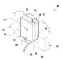
- FIG. 1is a perspective view showing a multi-connector according to an exemplary embodiment of the present invention before a second connector body pivots.
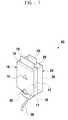
- FIG. 2is a perspective view showing the second connector body of the multi-connector in FIG. 1 once it has been pivoted.
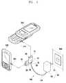
- FIG. 3is a view showing the use of a charging cable having the multi-connector according to an exemplary embodiment of the present invention.
- FIG. 4is a view showing the use of a data cable having the multi-connector according to an exemplary embodiment of the present invention.
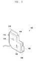
- FIG. 5is a perspective view showing a multi-connector according to another exemplary embodiment of the present invention.
- FIG. 1is a perspective view showing a multi-connector 40 according to an exemplary embodiment of the present invention before a second connector body 20 is pivoted.
- FIG. 2is a perspective view showing the second connector body 20 of the multi-connector 40 in FIG. 1 after it is pivoted.
- the multi-connector 40is a connector of a portable terminal including a first connector body 10 , the second connector body 20 , and a hinge shaft 30 .
- the first connector body 10includes a first connector 13 .
- the second connector body 20includes a second connector 23 .
- the first connector body 10 and the second connector body 20are coupled to the hinge shaft 30 to pivot.
- the first connector body 10has a first face 17 and a second face 18 opposite to the first face 17 .
- the first connector 13protrudes from a side 19 that connects ends of the first and second faces 17 and 18 to each other, and a first lamp 15 is installed on the first face 17 .
- the second connector body 20has a first face 27 and a second face 28 opposite to the first face 27 .
- the first face 27faces the second face 18 of the first connector body 10 .
- a second connector 23protrudes from a side 29 that connects ends of the first and second faces 27 and 28 to each other, and a second lamp 25 is installed on the first face 27 .
- the hinge shaft 30penetrates the first connector body 10 and the second connector body 20 to connect them to each other.
- the first connector body 10 and the second connector body 20can pivot about the hinge shaft 30 .
- the first and second connectors 13 and 23 of the respective sides 19 and 29 of the first and second connector bodies 10 and 20pivot correspondingly and may be connected to the portable terminal without interfering with each other when in the pivoted state.
- the first connector 13may be a 24-pin connector
- the second connector 23may be a 20-pin connector
- the first connector 13may be a model that is standardized by the KTTA and has 24 pins arranged in a line.
- the 24 pinsmay include seven charging pins, eight data communication pins, five hands free pins, and four other pins.
- the second connector 23may have 20 pins arranged in two lines.
- the 20 pinsmay include five charging pins, five data communication pins, five audio/video pins, and five other pins.
- the portable terminalmay be recharged and may perform data communication through the first and second connectors 13 and 23 .
- the first lamp 15is installed on the first face 17 of the first connector body 10 and the second lamp 25 is installed on the first face 27 of the second connector body 20 .
- the second lamp 25may be installed at a position of the first face 27 such that it is exposed when the second connector body 20 pivots about the hinge shaft 30 so a user may check the state of the second lamp 25 when the second connector 23 is being used.
- the first connector 13is a 24-pin connector and the second connector 23 is a 20-pin connector in this exemplary embodiment, the connectors are not limited thereto.
- the first connectormay be a 20-pin connector and the second connector may be a 24-pin connector.
- wires connected to the pins of the second connector 23may be connected to wires connected to the corresponding pins of the first connector 13 through an overlap portion of the first connector body 10 and the second connector body 20 when the second connector body 20 pivots about the hinge shaft 30 .
- the multi-connector 40may be connected to a charging cable 100 as shown in FIG. 3 , or a data cable 200 as shown in FIG. 4 .
- the charging cable 100 having the multi-connector 40includes the multi-connector 40 , a cable 50 , and a charging unit 60 .
- the charging cable 100has a structure in which the multi-connector 40 and the charging unit 60 are connected to ends of the cable 50 .
- the first connector body 10is connected to a first end of the cable 50 and the charging unit 60 is connected to a second end of the cable 50 that is opposite the first end of the cable 50 .
- the charging unit 60may include a power plug 61 inserted into an electric socket 500 to supply electric power, and a DC power unit 63 to convert AC power supplied through the power plug 61 into DC power.
- a first and/or second portable terminal 310 and 320may be charged using a charging cable 100 as follows.
- the first portable terminal 310includes a first socket 311 to receive the first connector 13 .
- the second portable terminal 320includes a second socket 321 to receive the second connector 23 .
- the userpivots the first connector body 10 and the second connector body 20 of the multi-connector 40 .
- the userinserts the first connector 13 into the first socket 311 of the first portable terminal 310 and inserts the second connector 23 into the second socket 321 of the second portable terminal 320 .
- the userputs the power plug 61 of the charging unit 60 into the socket 500 to charge the first and second portable terminals 310 and 320 .
- the first lamp 15 of the first connector body 10 and the second lamp 25 of the second connector body 20emit red light or blue light according to charging states of the first and second portable terminals 310 and 320 .
- the first and second lamps 15 and 25may emit red light during charging, and may emit blue light when charging is completed.
- the first lamp 15may twinkle when there is a loose contact between the first connector 13 and the first socket 311
- the second lamp 25may twinkle when there is a loose contact between the second connector 23 and the second socket 321 .
- the usermay confirm the charging and connection statuses of the first and second portable terminals 310 and 320 by the red light or the blue light emitted from the first and second lamps 15 and 25 of the first and second connector bodies 10 and 20 .
- first and second portable terminals 310 and 320are connected to the first and second connectors 13 and 23 of the charging cable 100 at the same time in this exemplary embodiment, only one of the portable terminals 310 and 320 is connected to the charging cable at a time in other exemplary embodiments.
- the data cable 200 having the multi-connector 40includes the multi-connector 40 , a cable 50 , and a universal serial bus (USB) connector 70 .
- the data cable 200has a structure in which the multi-connector 40 and the USB connector 70 are connected to ends of the cable 50 .
- the first connector body 10is connected to a first end of the cable 50 and the USB connector 70 is connected to a second end of the cable 50 that is opposite the first end of the cable 50 .
- a first or second portable terminal 310 or 320may be connected to a laptop computer 700 using a data cable 200 as follows.
- the first portable terminal 310includes a first socket 311 to receive the first connector 13 .
- the second portable terminal 320includes a second socket 321 to receive the second connector 23 .
- the laptop computer 700includes a USB socket 711 to receive the USB connector 70 .
- the userpivots the first connector body 10 and the second connector body 20 of the multi-connector 40 .
- the userinserts the first connector 13 into the first socket 311 of the first portable terminal 310 or the second connector 23 into the second socket 321 of the second portable terminal 320 .
- the userinserts the USB connector 70 into the USB socket 711 of the laptop computer 700 to connect the first and second portable terminals 310 or 320 to the laptop computer 700 .
- the first lamp 15 of the first connector body 10 and the second lamp 25 of the second connector body 20may emit red light according to connection states of the first and second portable terminals 310 and 320 .
- the first lamp 15may twinkle.
- the second lamp 25may twinkle.
- the usermay confirm the connection statuses of the first and second portable terminals 310 and 320 by the red light emitted from the first and second lamps 15 and 25 of the first and second connector bodies 10 and 20 .
- the first and second portable terminals 310 and 320are connected to the first and second connectors 13 and 23 of the data cable 200 at the same time, only one of the portable terminals 310 and 320 may be connected to the data cable 200 at a time in other exemplary embodiments.
- the first and second portable terminals 310 and 320may be charged through the data cable 200 connected to the laptop computer 700 .
- the first or second portable terminal 310 or 320may be charged or the data communication may be performed between the first or second portable terminal 310 or 320 and the laptop computer 700 .
- FIG. 5is a perspective view showing a multi-connector 140 according to another exemplary embodiment of the present invention.
- the multi-connector 140includes a connector body 110 , and first and second connectors 113 and 123 formed in the connector body 110 .
- the first connector 113protrudes from a first side of the connector body 110 .
- the second connector 123protrudes from a second side of the connector body 110 in a direction different from that of the first side from which the first connector 113 protrudes.
- the L-shaped connector body 110has first and second ends 119 and 129 from which the first and second connectors 113 and 123 protrude, respectively.
- First and second lamps 115 and 125are installed on faces neighboring the first and second ends 119 and 129 from which the first and second connectors 113 and 123 protrude.
- the first lamp 115is installed near the first connector 113 and the second lamp 125 is installed near the second connector 123 .
- the first connector 113may be a 24-pin connector
- the second connector 123may be a 20-pin connector.
- the usermay selectively connect the first or second connector 113 or 123 to the portable terminal to charge the portable terminal or to perform the data communication.
- the multi-connector 140may be a charging cable or a data cable.
Landscapes
- Charge And Discharge Circuits For Batteries Or The Like (AREA)
- Connector Housings Or Holding Contact Members (AREA)
- Details Of Connecting Devices For Male And Female Coupling (AREA)
- Telephone Set Structure (AREA)
Abstract
Description
Claims (11)
Applications Claiming Priority (2)
| Application Number | Priority Date | Filing Date | Title |
|---|---|---|---|
| KR10-2007-0125252 | 2007-12-05 | ||
| KR1020070125252AKR101402807B1 (en) | 2007-12-05 | 2007-12-05 | Multi connector, charging cable and data cable having the multi connector |
Publications (2)
| Publication Number | Publication Date |
|---|---|
| US20090149050A1 US20090149050A1 (en) | 2009-06-11 |
| US8096820B2true US8096820B2 (en) | 2012-01-17 |
Family
ID=40722124
Family Applications (1)
| Application Number | Title | Priority Date | Filing Date |
|---|---|---|---|
| US12/275,618Expired - Fee RelatedUS8096820B2 (en) | 2007-12-05 | 2008-11-21 | Multi-connector, and charging cable and data cable having the same |
Country Status (2)
| Country | Link |
|---|---|
| US (1) | US8096820B2 (en) |
| KR (1) | KR101402807B1 (en) |
Cited By (8)
| Publication number | Priority date | Publication date | Assignee | Title |
|---|---|---|---|---|
| USD671951S1 (en)* | 2012-01-05 | 2012-12-04 | Midas Mana Technology SDN.BHD. | USB device |
| US20120329331A1 (en)* | 2011-03-18 | 2012-12-27 | Wen-Yung Liao | Usb connector |
| US20150140843A1 (en)* | 2013-11-20 | 2015-05-21 | Foxconn Interconnect Technology Limited | Cable connector assembly having several plug connectors |
| US10033294B2 (en)* | 2014-11-13 | 2018-07-24 | Ricot Riphin | Folding plug with safety cover |
| US10346643B2 (en)* | 2017-08-30 | 2019-07-09 | Kepco Engineering & Construction Company, Inc. | Universal serial bus security device using crank-type bidirectional universal serial bus socket |
| USD890761S1 (en) | 2018-11-27 | 2020-07-21 | Cisco Technology, Inc. | Multi-connector hub |
| US10958025B2 (en)* | 2018-12-18 | 2021-03-23 | D'addario & Company, Inc. | Pivoting plug adapter |
| US11101584B2 (en)* | 2019-09-02 | 2021-08-24 | Dongguan Yuanchuang Electronic Technology Co., Ltd | Data cable |
Families Citing this family (12)
| Publication number | Priority date | Publication date | Assignee | Title |
|---|---|---|---|---|
| GB201114250D0 (en)* | 2010-09-28 | 2011-10-05 | Yota Group Cyprus Ltd | Connector and device |
| KR20130096612A (en)* | 2012-02-22 | 2013-08-30 | 주식회사 엔소닉스 | Iport for connected to usb port and 30 pin port for iphone with compatibility, and private cable for iport |
| KR101321575B1 (en)* | 2012-03-07 | 2013-10-28 | 김성두 | Rechargeable device |
| KR101870704B1 (en)* | 2012-03-28 | 2018-06-25 | 삼성전자 주식회사 | Adapter for connecting two mobile device each other |
| GB201317624D0 (en)* | 2013-10-04 | 2013-11-20 | Aquaterra Ltd | Multifunctional interface unit |
| CN106233546B (en)* | 2014-07-28 | 2019-08-13 | 惠普发展公司,有限责任合伙企业 | Docking station with swivel multi-plug connector |
| CN205122871U (en)* | 2015-11-17 | 2016-03-30 | 刘春� | Mobile phone charging plug connector |
| US9935413B1 (en)* | 2016-02-18 | 2018-04-03 | Apple Inc. | Hinge pin with electrical connection through a cylindrical pin body |
| DE102016004527B3 (en) | 2016-04-13 | 2017-05-11 | Rosenberger Hochfrequenztechnik Gmbh & Co. Kg | Calibration arrangement and method for operating a calibration arrangement |
| KR101698981B1 (en)* | 2016-08-02 | 2017-01-23 | 주식회사 코마홀딩스 | A plug that supports heterogeneous interface and a cable apparatus having the plug |
| GB2569424B (en)* | 2017-11-27 | 2022-11-23 | David Jeffries Spencer | Apparatus |
| KR200491158Y1 (en) | 2018-11-01 | 2020-02-26 | 주식회사 모바텍 | Cable for Data and Charging Combined Strap of Portable Terminal |
Citations (9)
| Publication number | Priority date | Publication date | Assignee | Title |
|---|---|---|---|---|
| US6289402B1 (en)* | 1993-07-23 | 2001-09-11 | Amiga Development Llc | Bidirectional data transfer protocol primarily controlled by a peripheral device |
| US20030034756A1 (en)* | 2001-08-15 | 2003-02-20 | Rong-Chun Chang | Swivel-jointed voltage-stepping automobile charger |
| US6676420B1 (en)* | 2002-04-19 | 2004-01-13 | Wen-Tsung Liu | Double interface compact flash memory card |
| US6733328B2 (en)* | 2002-05-02 | 2004-05-11 | Chen Che Lin | USB cable adapter with cable winding mechanism |
| US20060088018A1 (en)* | 2004-09-24 | 2006-04-27 | Tom Black | System and method for communicating over an 802.15.4 network |
| US20060236175A1 (en)* | 2005-04-05 | 2006-10-19 | Shiro Usami | Semiconductor integrated circuit device and I/O cell for the same |
| US20060293080A1 (en)* | 2005-06-02 | 2006-12-28 | Samsung Electronics Co., Ltd. | Connector assembly for connecting mobile phone to peripheral device |
| US20070182365A1 (en)* | 2006-01-27 | 2007-08-09 | Tai-Her Yang | Charger with primary battery for two-way I/O |
| US20090039827A1 (en)* | 2007-08-08 | 2009-02-12 | David Fowler | Solar-Powered Charger With Heat-Dissipating Surface |
Family Cites Families (4)
| Publication number | Priority date | Publication date | Assignee | Title |
|---|---|---|---|---|
| KR20060065216A (en)* | 2004-12-10 | 2006-06-14 | 브이케이 주식회사 | UsB connection device between computer and mobile communication terminal |
| KR20060120303A (en)* | 2005-05-19 | 2006-11-27 | 삼성전자주식회사 | Connecting device between mobile terminal and external device |
| KR200396876Y1 (en) | 2005-07-14 | 2005-09-27 | 테-성 린 | Computer Cable, Junction Box For Use With Computer Cable |
| KR20060116708A (en)* | 2006-05-04 | 2006-11-15 | 임기영 | Charging Connector |
- 2007
- 2007-12-05KRKR1020070125252Apatent/KR101402807B1/ennot_activeExpired - Fee Related
- 2008
- 2008-11-21USUS12/275,618patent/US8096820B2/ennot_activeExpired - Fee Related
Patent Citations (9)
| Publication number | Priority date | Publication date | Assignee | Title |
|---|---|---|---|---|
| US6289402B1 (en)* | 1993-07-23 | 2001-09-11 | Amiga Development Llc | Bidirectional data transfer protocol primarily controlled by a peripheral device |
| US20030034756A1 (en)* | 2001-08-15 | 2003-02-20 | Rong-Chun Chang | Swivel-jointed voltage-stepping automobile charger |
| US6676420B1 (en)* | 2002-04-19 | 2004-01-13 | Wen-Tsung Liu | Double interface compact flash memory card |
| US6733328B2 (en)* | 2002-05-02 | 2004-05-11 | Chen Che Lin | USB cable adapter with cable winding mechanism |
| US20060088018A1 (en)* | 2004-09-24 | 2006-04-27 | Tom Black | System and method for communicating over an 802.15.4 network |
| US20060236175A1 (en)* | 2005-04-05 | 2006-10-19 | Shiro Usami | Semiconductor integrated circuit device and I/O cell for the same |
| US20060293080A1 (en)* | 2005-06-02 | 2006-12-28 | Samsung Electronics Co., Ltd. | Connector assembly for connecting mobile phone to peripheral device |
| US20070182365A1 (en)* | 2006-01-27 | 2007-08-09 | Tai-Her Yang | Charger with primary battery for two-way I/O |
| US20090039827A1 (en)* | 2007-08-08 | 2009-02-12 | David Fowler | Solar-Powered Charger With Heat-Dissipating Surface |
Cited By (10)
| Publication number | Priority date | Publication date | Assignee | Title |
|---|---|---|---|---|
| US20120329331A1 (en)* | 2011-03-18 | 2012-12-27 | Wen-Yung Liao | Usb connector |
| US8550828B2 (en)* | 2011-03-18 | 2013-10-08 | Wen-Yung Liao | USB connector |
| USD671951S1 (en)* | 2012-01-05 | 2012-12-04 | Midas Mana Technology SDN.BHD. | USB device |
| US20150140843A1 (en)* | 2013-11-20 | 2015-05-21 | Foxconn Interconnect Technology Limited | Cable connector assembly having several plug connectors |
| US9385464B2 (en)* | 2013-11-20 | 2016-07-05 | Foxconn Interconnect Technology Limited | Cable connector assembly having several plug connectors |
| US10033294B2 (en)* | 2014-11-13 | 2018-07-24 | Ricot Riphin | Folding plug with safety cover |
| US10346643B2 (en)* | 2017-08-30 | 2019-07-09 | Kepco Engineering & Construction Company, Inc. | Universal serial bus security device using crank-type bidirectional universal serial bus socket |
| USD890761S1 (en) | 2018-11-27 | 2020-07-21 | Cisco Technology, Inc. | Multi-connector hub |
| US10958025B2 (en)* | 2018-12-18 | 2021-03-23 | D'addario & Company, Inc. | Pivoting plug adapter |
| US11101584B2 (en)* | 2019-09-02 | 2021-08-24 | Dongguan Yuanchuang Electronic Technology Co., Ltd | Data cable |
Also Published As
| Publication number | Publication date |
|---|---|
| KR101402807B1 (en) | 2014-06-02 |
| US20090149050A1 (en) | 2009-06-11 |
| KR20090058613A (en) | 2009-06-10 |
Similar Documents
| Publication | Publication Date | Title |
|---|---|---|
| US8096820B2 (en) | Multi-connector, and charging cable and data cable having the same | |
| US7501792B2 (en) | Charging cable with USB-like connector | |
| CN101136528B (en) | Adaptor and wireless communication module | |
| CN103730799B (en) | Combined-type adapter plug | |
| US20080143185A1 (en) | System for Supplying Power for Peripheral Devices | |
| JP2013099243A (en) | Modularized wall outlet | |
| US10931074B2 (en) | Assembly of worldwide AC adapter supporting foldable prongs | |
| JP2000201204A (en) | Auxiliary charging device for portable telephone set | |
| CN101640356B (en) | Connectors, electronic devices with connectors and electronic components | |
| US20140367138A1 (en) | Power adapter | |
| US20130344705A1 (en) | Electrical connector | |
| KR200448194Y1 (en) | Mobile Phone Gender with Secondary Battery | |
| TWM484174U (en) | Flash drive | |
| US20140199888A1 (en) | Apparatus, system and method for composite and symmetrical hybrid electronic connectors | |
| TWM484780U (en) | Storage device | |
| CN218242503U (en) | Adapter | |
| CN202586515U (en) | Adapter for wireless charging | |
| CN205864010U (en) | Mobile electronic device charging device | |
| CN212277568U (en) | Adapter with circuit protection | |
| CN220984999U (en) | Electric connection structure, board end and wire end connector, patch cord and connecting assembly | |
| CN204885691U (en) | Plug electric connector and cable assembly with same | |
| CN114442740B (en) | Power supply module | |
| CN2351888Y (en) | electrical connector combination | |
| CN211669462U (en) | Glasses and glasses case | |
| TWI751503B (en) | Wire arranging module |
Legal Events
| Date | Code | Title | Description |
|---|---|---|---|
| AS | Assignment | Owner name:SAMSUNG ELECTRONICS CO., LTD., KOREA, REPUBLIC OF Free format text:ASSIGNMENT OF ASSIGNORS INTEREST;ASSIGNORS:LYU, MIN JEONG;LEE, BYOUNG SOO;CHOI, JAE SEOK;REEL/FRAME:021934/0233 Effective date:20081121 | |
| ZAAA | Notice of allowance and fees due | Free format text:ORIGINAL CODE: NOA | |
| ZAAB | Notice of allowance mailed | Free format text:ORIGINAL CODE: MN/=. | |
| FEPP | Fee payment procedure | Free format text:PAYOR NUMBER ASSIGNED (ORIGINAL EVENT CODE: ASPN); ENTITY STATUS OF PATENT OWNER: LARGE ENTITY | |
| STCF | Information on status: patent grant | Free format text:PATENTED CASE | |
| FPAY | Fee payment | Year of fee payment:4 | |
| MAFP | Maintenance fee payment | Free format text:PAYMENT OF MAINTENANCE FEE, 8TH YEAR, LARGE ENTITY (ORIGINAL EVENT CODE: M1552); ENTITY STATUS OF PATENT OWNER: LARGE ENTITY Year of fee payment:8 | |
| FEPP | Fee payment procedure | Free format text:MAINTENANCE FEE REMINDER MAILED (ORIGINAL EVENT CODE: REM.); ENTITY STATUS OF PATENT OWNER: LARGE ENTITY | |
| LAPS | Lapse for failure to pay maintenance fees | Free format text:PATENT EXPIRED FOR FAILURE TO PAY MAINTENANCE FEES (ORIGINAL EVENT CODE: EXP.); ENTITY STATUS OF PATENT OWNER: LARGE ENTITY | |
| STCH | Information on status: patent discontinuation | Free format text:PATENT EXPIRED DUE TO NONPAYMENT OF MAINTENANCE FEES UNDER 37 CFR 1.362 | |
| FP | Lapsed due to failure to pay maintenance fee | Effective date:20240117 |