US8095327B2 - Power supply apparatus for operation - Google Patents
Power supply apparatus for operationDownload PDFInfo
- Publication number
- US8095327B2 US8095327B2US12/103,049US10304908AUS8095327B2US 8095327 B2US8095327 B2US 8095327B2US 10304908 AUS10304908 AUS 10304908AUS 8095327 B2US8095327 B2US 8095327B2
- Authority
- US
- United States
- Prior art keywords
- temperature
- surgical instrument
- abnormality
- probe
- ultrasonic
- Prior art date
- Legal status (The legal status is an assumption and is not a legal conclusion. Google has not performed a legal analysis and makes no representation as to the accuracy of the status listed.)
- Active, expires
Links
Images


Classifications
- A—HUMAN NECESSITIES
- A61—MEDICAL OR VETERINARY SCIENCE; HYGIENE
- A61B—DIAGNOSIS; SURGERY; IDENTIFICATION
- A61B17/00—Surgical instruments, devices or methods
- A61B17/32—Surgical cutting instruments
- A61B17/320068—Surgical cutting instruments using mechanical vibrations, e.g. ultrasonic
- A—HUMAN NECESSITIES
- A61—MEDICAL OR VETERINARY SCIENCE; HYGIENE
- A61B—DIAGNOSIS; SURGERY; IDENTIFICATION
- A61B17/00—Surgical instruments, devices or methods
- A61B2017/00017—Electrical control of surgical instruments
- A61B2017/00022—Sensing or detecting at the treatment site
- A61B2017/00084—Temperature
- A—HUMAN NECESSITIES
- A61—MEDICAL OR VETERINARY SCIENCE; HYGIENE
- A61B—DIAGNOSIS; SURGERY; IDENTIFICATION
- A61B17/00—Surgical instruments, devices or methods
- A61B17/32—Surgical cutting instruments
- A61B17/320068—Surgical cutting instruments using mechanical vibrations, e.g. ultrasonic
- A61B2017/320069—Surgical cutting instruments using mechanical vibrations, e.g. ultrasonic for ablating tissue
- A—HUMAN NECESSITIES
- A61—MEDICAL OR VETERINARY SCIENCE; HYGIENE
- A61B—DIAGNOSIS; SURGERY; IDENTIFICATION
- A61B17/00—Surgical instruments, devices or methods
- A61B17/32—Surgical cutting instruments
- A61B17/320068—Surgical cutting instruments using mechanical vibrations, e.g. ultrasonic
- A61B2017/320071—Surgical cutting instruments using mechanical vibrations, e.g. ultrasonic with articulating means for working tip
- A—HUMAN NECESSITIES
- A61—MEDICAL OR VETERINARY SCIENCE; HYGIENE
- A61B—DIAGNOSIS; SURGERY; IDENTIFICATION
- A61B17/00—Surgical instruments, devices or methods
- A61B17/32—Surgical cutting instruments
- A61B17/320068—Surgical cutting instruments using mechanical vibrations, e.g. ultrasonic
- A61B2017/320082—Surgical cutting instruments using mechanical vibrations, e.g. ultrasonic for incising tissue
Definitions
- the present inventionrelates to a power supply apparatus for operation.
- a drive apparatus for an ultrasonic vibratoris hitherto known as a power supply apparatus for operation.
- a probe from which a resonant frequency is output by phase-locked loop (PLL) controlis described
- PLLphase-locked loop
- Jpn. Pat. Appln. KOKAI Publication No. 2003-159259a method for distinguishing breakage of a defective hand-piece in an ultrasonic surgical system and breakage of a defective blade from each other is disclosed.
- US2002-0049551a method for clarifying a difference between a loaded blade and a cracked blade by evaluating a measured impedance difference is disclosed.
- a first aspect of the present inventionrelates to a power supply apparatus for operation for outputting power to a surgical instrument, the apparatus comprising: a temperature detection section for detecting a temperature of the surgical instrument; and an abnormality detection section for detecting an abnormality of the surgical instrument on the basis of the detected temperature.
- a second aspect of the present inventionrelates to the first aspect, and the temperature detection section detects the temperature by measuring the electric capacitance of the surgical instrument or directly measures the temperature of the surgical instrument by using a temperature measurement device.
- a third aspect of the present inventionrelates to the first aspect, and the abnormality detection section detects the abnormality according to whether or not a temperature variation amount of the surgical instrument per unit time exceeds a predetermined threshold.
- a fourth aspect of the present inventionrelates to any one of the first to third aspects, and the abnormality detection section further detects the abnormality according to whether or not a variation amount of a resonant frequency of the surgical instrument per unit time exceeds a variation amount of the resonant frequency resulting from a temperature change per predetermined unit time.
- a fifth aspect of the present inventionrelates to any one of the first to third aspects, and when the abnormality detection section detects an abnormality, the abnormality detection section stops the output of the power to the surgical instrument.
- a sixth aspect of the present inventionrelates to any one of the first to third aspects, and the surgical instrument is provided with an ultrasonic vibrator and a probe for transmitting the vibration of the ultrasonic vibrator to a distal end thereof, and the power to be output from the apparatus is ultrasonic power for driving the ultrasonic vibrator.
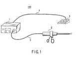
- FIG. 1is an external perspective view of an ultrasonic operation system.
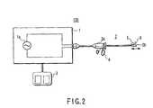
- FIG. 2is a view showing a schematic configuration of the ultrasonic operation system.
- FIG. 3is a view showing a state where a drive current generated in an ultrasonic power source unit flows to the hand-piece side.
- FIG. 4is a view showing a relationship between a voltage phase and a current phase.
- FIG. 5is a view for explaining a procedure for scanning for a resonant frequency fr.
- FIG. 6is a view showing a probe part in an enlarging manner.
- (B) and (C) in FIG. 6are graphs showing frequency dependence of the impedance Z, current I, and phase difference ( ⁇ V ⁇ I) which are under the PLL control observed when a crack develops in a probe in a normal state.
- FIG. 7is a schematic view for explaining a first embodiment, and showing magnitude of each factor in the causation of a variation in a capacitance component.
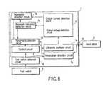
- FIG. 8is a functional block diagram for explaining a function of each unit in an ultrasonic power source unit in an ultrasonic operation system.
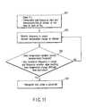
- FIG. 9is a flowchart for detecting an abnormality of a probe according to a first embodiment.
- FIG. 10is a flowchart for detecting an abnormality of a probe according to a second embodiment.
- FIG. 11is a flowchart for detecting an abnormality of a probe according to a third embodiment.
- FIG. 12is a functional block diagram for explaining a function of each unit in an ultrasonic power source unit in an ultrasonic operation system according to a fourth embodiment.
- FIG. 1is an external perspective view of an ultrasonic operation system used as an example of a system for such an endoscopic surgical operation.
- the ultrasonic operation systemis constituted of an ultrasonic power source unit 1 serving as a power supply apparatus for operation for generating an ultrasonic output for driving an ultrasonic vibrator which is a surgical instrument, a hand-piece 2 serving as an ultrasonic surgical instrument for performing treatment by using an ultrasonic output supplied from the ultrasonic power source unit 1 through a cable 5 , and a foot switch 3 connected to the ultrasonic power source unit 1 through a cable 4 , for controlling the ultrasonic output from the ultrasonic power source unit 1 .
- the ultrasonic vibratorfor example, a bolt-clamped Langevin type transducer (BLT) is known.
- the hand-piece 2is constituted of a hand-piece main body section 2 a which includes handles 4 , and in which an ultrasonic vibrator (not shown) is incorporated, and a probe 2 b for transmitting vibration of the ultrasonic vibrator to a treatment section 5 .
- the ultrasonic power source unit 1is provided with an ultrasonic oscillator circuit 1 a for generating electric energy for vibrating the ultrasonic vibrator.
- An electric signal output from the ultrasonic power source unit 1is converted into mechanical vibration (ultrasonic vibration) by the ultrasonic vibrator inside the hand-piece main body section 2 a , and thereafter the vibration is transmitted by the probe 2 b to the treatment section 5 .
- the treatment section 5is provided with a grasping section 6 called a jaw driven to be opened or closed with respect to the distal end of the probe 2 b.
- a grasping section 6called a jaw driven to be opened or closed with respect to the distal end of the probe 2 b.
- the grasping section 6is driven to be opened or closed with respect to the distal end of the probe 2 b , and coagulation or incision of living tissue is performed by utilizing frictional heat generated by holding the living tissue between the distal end of the probe 2 b and the grasping section 6 and applying the ultrasonic vibration thereto.
- a crackis caused due to a scratch received when the probe 2 b comes into contact with forceps or a clip during an operation.
- a crackis caused to the probe 2 b during an operation, it is necessary to immediately stop ultrasonic vibration, and replace the probe with a new one. If the operation is continued in the state where the crack is caused to the probe, it is conceivable that there is the possibility of the probe part being broken and falling off. Accordingly, it becomes necessary to detect the occurrence of the crack at an early stage, and inform the medical pursuer of the occurrence of the crack.
- the ultrasonic operation systemwill be described below in detail, and an apparatus and a method for exactly detecting an occurrence of a crack in a probe in an early stage will be described.
- FIGS. 3 to 5are views for explaining a method of controlling ultrasonic drive in an ultrasonic operation system.
- a sinusoidal drive voltage VSINis generated in an ultrasonic oscillator circuit 1 a .
- a sinusoidal drive current ISIN corresponding to the sinusoidal drive voltage VSINflows into the ultrasonic vibrator inside the hand-piece main body section 2 a .
- the ultrasonic vibratorconverts the electric signal into mechanical vibration, and transmits the mechanical vibration to the distal end of the probe 2 b .
- the ultrasonic vibrationis output at a constant oscillation frequency, a phase difference occurs between the voltage V and the current I, and hence the drive efficiency lowers.
- a control circuitis provided in the ultrasonic power source unit 1 , and the drive of the ultrasonic vibrator is performed while a resonance point at which a phase difference between the voltage V and the current I becomes 0 ((B) in FIG. 4 ) is searched for.
- the abscissaindicates the frequency f
- the ordinateindicates the impedance Z, current I, and phase difference ( ⁇ V ⁇ I).
- a value ( ⁇ V ⁇ I)indicates a phase difference.
- a resonant frequency fr at which the phase difference ( ⁇ V ⁇ I) becomes 0is detected by scanning for a point at which the impedance Z is minimized while consecutively changing the frequency.
- the control circuit 1 cstarts to perform the drive of the ultrasonic vibrator at the detected resonant frequency fr.
- FIG. 6are views for explaining a method of investigating an abnormality of a hand-piece 2 according to a first embodiment.
- (A) in FIG. 6is a view showing a probe 2 b part of the hand-piece 2 in an enlarging manner. This view schematically shows a state where the probe 2 b has a crack 10 .
- the term crackdoes not necessarily imply a crack that can be confirmed with the naked eye, and includes a crack that does not appear externally, such as an internal crack, and a microcrack that appears at the early stage of metal fatigue.
- the term crackdoes not necessarily imply a crack that can be confirmed with the naked eye, and includes a crack that does not appear externally, such as an internal crack, and a microcrack that appears at the early stage of metal fatigue.
- the actual crack measurementnot only megascopic observation, but also microscopic observation using a magnifying glass, a metallurgical microscope or the like, and observation of a crack (microcrack) in the order of microns using
- FIG. 6are graphs showing frequency dependence of the impedance Z, current I, and phase difference ( ⁇ V ⁇ I) which are under the PLL control observed when a crack has developed in the probe 2 b in the normal state.
- the probeis not yet damaged, and the impedance Z, current I, and phase difference ( ⁇ V ⁇ I) which are in the normal state are shown.
- the frequencyis varied by the PLL control such that the phase difference ( ⁇ V ⁇ I) becomes zero degree.
- the phase difference ( ⁇ V ⁇ I)becomes also zero degree in the vicinity of a frequency at which the impedance Z becomes the lowest. Accordingly, this frequency fr is the resonant frequency.
- FIG. 6shows a graph of the impedance Z, current I, and phase difference ( ⁇ V ⁇ I) under the PLL control observed after the probe 2 b is cracked.
- the phase difference ( ⁇ V ⁇ I)is shifted, and the impedance is also largely varied.
- the PLL controlis performed such that the impedance becomes the minimum, and a new resonant frequency fr′ is searched for.
- (C) in FIG. 6shows the impedance Z, current I, and phase difference ( ⁇ V ⁇ I) observed after the search, and it can be seen that the control is performed such that the phase difference ( ⁇ V ⁇ I) becomes in the vicinity of zero at the new resonant frequency fr′.
- the minimum value of the impedance Zis larger than that at (B) in FIG. 6 , and the value of the phase difference ( ⁇ V ⁇ I) is also at a value (dotted line) higher than the zero value (broken line) before the occurrence of the crack by ⁇ P.
- the degree of the positive/negative magnitude, and the polaritiesare shown schematically and rectangularly only for easy understanding.
- the characters ⁇ P indicating the variation in the phase difference ( ⁇ V ⁇ I)can also be produced by factors other than the crack in the probe. However, the value is several degrees or less, and a variation exceeding 10 degrees is attributable to a crack.
- the impedance Zis varied by the crack produced in the probe 2 b. Particularly, an electric capacitance component of the impedance is increased. It was found that this electric capacitance component was increased due to the temperature rise of the ultrasonic vibrator serving as a surgical instrument.
- the reason why the temperature of the ultrasonic vibrator is raisedcan be conceivable that the probe 2 b cannot sufficiently exhibit the function of the probe serving as a complete vibration transmitting element of the ultrasonic vibrator due to the crack, and another unintended vibration mode resulting from the crack has occurred. Another unintended vibration mode is superposed on the normal vibration mode, or interferes the normal vibration mode. Further, the normal vibration mode and another unintended vibration mode interfere with each other, and a large periodic vibration mode is caused in some cases. It is conceivable that heat is abnormally generated in the ultrasonic vibrator by these vibration modes, and the increase in the electric capacitance is caused by the generation of heat.
- FIG. 7shows the magnitude of each factor in the causation of a variation in the electric capacitance by the size of the arrow.
- the factors in the causation of the variation in the capacitance componentthe variation in the product resulting from the manufacture, use environment temperature, and temperature rise during use which become larger in the order mentioned are present. From the above fact, when the unintended vibration mode is caused by the crack 10 of the probe 2 b , the temperature is further more raised as compared with the temperature rise in the normal use. Thus, it can be understood that the variation in the capacitance component resulting from the above is the largest. The temperature rise during normal use differs depending on the type of the ultrasonic vibrator.
- a temperature rise of a maximum of 10° C.is observed during use, and in another type of ultrasonic vibrator, a temperature rise of a maximum of 30° C. is observed.
- a variation in the electric capacitance of about 72 to 180 pFis observed.
- the correlation between the temperature rise of the ultrasonic vibrator and the variation in the resonant frequencycan be measured in advance.
- the temperature of the ultrasonic vibratoris well correlated with the electric capacitance of the ultrasonic vibrator. Accordingly, the tempaerature of the ultrasonic vibrator can be obtained with high accuracy by measuring, for example, the electric capacitance of the ultrasonic vibrator, and the variation amount of the resonant frequency can also be estimated on the basis of the temperature.
- the electric capacitanceis changed by the abnormal heat generation of the ultrasonic vibrator, and the impedance including the electric capacitance is also changed. It is conceivable that as a result of this, the frequency characteristic of the impedance is changed, and the frequency dependence of the phase difference ( ⁇ V ⁇ I) between the voltage and the current is also changed. On the basis of these results, it is possible to measure that a crack 10 has been produced in the probe 2 b by monitoring the temperature of the ultrasonic vibrator under the PLL control or by monitoring the temperature of the hand-piece 2 including the ultrasonic vibrator.
- thermocouplewhich is a temperature measurement device.
- the temperature measurement to be mentioned hereafterimplies both the temperature measurement in which calculation is based on the electric capacitance measurement, and the measurement performed by directly using a thermistor or a thermocouple.
- FIG. 8is a functional block diagram for explaining a function of each unit in an ultrasonic power source unit in an ultrasonic operation system.
- the hand-piece 2is connected to the ultrasonic power source unit 1 through a connector 1 e.
- an ultrasonic oscillator circuit 1 aIn the ultrasonic power source unit 1 , an ultrasonic oscillator circuit 1 a , output voltage/output current detection circuit 1 f , impedance detection circuit 1 g , resonant frequency detection circuit 1 h , temperature detection circuit 1 b , foot switch detection circuit 1 d , and control circuit 1 c are provided.
- the ultrasonic oscillator circuit 1 ais a part for generating a drive signal for driving the ultrasonic vibrator inside the hand-piece 2 .
- the foot switch detection circuit 1 dis a part for detecting that the foot switch 3 has been operated by the operator.
- the operation signalis transmitted to the control circuit 1 c through the foot switch detection circuit 1 d .
- the control circuit 1 cperforms control such that the ultrasonic power is output from the ultrasonic oscillator circuit 1 a to the hand-piece 2 .
- the output voltage/output current detection circuit 1 fis a part for detecting an output voltage and an output current of the power supplied from the ultrasonic oscillator circuit 1 a to the ultrasonic vibrator.
- the values of the output voltage and the output current detected by the output voltage/output current detection circuit 1 fare input to the impedance detection circuit 1 g and the resonant frequency detection circuit 1 h.
- the impedance detection circuit 1 gdetects the impedance by using the impedance detection algorithm of the hand-piece 2 on the basis of the values of the input output voltage and the input output current, and the phase difference between them.
- the impedance measured herecan be separated into an electric capacitance component and an electric conductance component. In the temperature measurement to be described later, the temperature can be calculated by using the electric capacitance component.
- the resonant frequency detection circuit 1 hdetects a frequency actually applied to the probe 2 b from the output voltage and the output current detected by the output voltage/output current detection circuit 1 f , and at the same time, monitors a variation in the impedance value transmitted from the impedance detection circuit 1 g . A frequency at which the value of the impedance abruptly changes is obtained, and detected as the resonant frequency.
- the temperature detection circuit 1 bmay calculate the temperature from the electric capacitance measurement of the hand-piece 2 , or may directly measure the temperature by using a thermistor or a thermocouple provided in the hand-piece 2 .
- the impedance detection circuit 1 gtransmits the measured electric capacitance to the temperature detection circuit 1 b , and the temperature detection circuit 1 b can calculate the temperature from the electric capacitance transmitted thereto on the basis of a correlation between the temperature measured in advance and the electric capacitance.
- a signal detected by, for example, a thermistor or a thermocouplemay be introduced into the temperature detection circuit 1 b , and the temperature measurement may be performed chronologically.
- the temperature measured by the temperature detection circuit 1 bis stored in the internal storage part. More specifically, the value of the temperature is saved in a memory which is the storage part at intervals of, for example, 5 msec, and the consecutively measured value of the temperature and the previously saved value of the temperature are compared with each other. Further, the value of the temperature measured at intervals of 5 msec is compared with plural values of the temperature such as values measured 5 msec ago, 10 msec ago, 15 msec ago, and so on, thereby judging whether or not the variation in the value of the temperature is not abnormal.
- the control circuit 1 cstarts the PLL control, and the abnormality detection circuit 1 k detects the initial temperature of the ultrasonic vibrator, and stores the detected data (step S 1 ).
- the PLL controlis the control necessary for the ultrasonic probe to perform an operation with increased energy efficiency.
- the abnormality detection circuit 1 kmonitors the variation in the temperature at intervals of a fixed sampling time determined in advance (step S 2 ).
- the monitored temperatureis compared with a plurality of resonant frequency data items detected previously.
- the abnormality detection circuit 1 kcompares the temperature with a predetermined threshold, for example, 30° C. (step S 3 ), and judges that the probe is abnormal when the temperature value is larger than the threshold (step S 4 ). When the temperature value is smaller than the threshold, the abnormality detection circuit 1 k judges that the probe 2 b is normal, and returns to step S 2 to continue monitoring the variation in the temperature.
- a correlation between the actually measured value of the temperature and the crack occurrence status of the probe 2 bwas measured. As a result of the measurement, when the variation in the temperature exceeds 30° C., a crack that can be visually confirmed, or a microcrack that can be confirmed by using an electron microscope occurred.
- the probewhen the probe is judged to be abnormal, it is possible to stop or shut down the ultrasonic output, and prevent breakage or falling off of the probe greater than the crack.
- the temperatureis detected on the basis of the measurement of the electric capacitance or on the basis of direct measurement, the variation value of the temperature is monitored, and a temperature variation value different from a temperature variation value resulting from resection or the like of living tissue by an ordinary operation is detected as an abnormality, whereby it is possible to instantaneously and easily grasp an occurrence of a crack in the probe.
- the medical staffcan replace the probe before the breakage of the probe occurs, and safely continue the treatment of the patient.
- Steps S 1 and S 2 in the flowchart of FIG. 9correspond to steps S 11 and S 12 in the flowchart of FIG. 10 , and hence a detailed description will be omitted.
- the temperature monitored in step S 12is compared with a plurality of temperature data items detected previously.
- an abnormality detection circuit 1 kcompares a variation in the temperature per unit time (100 msec) with a predetermined threshold, for example, 1° C./100 msec (step S 13 ), and when the variation is larger than the threshold, the abnormality detection circuit 1 k judges that the probe is abnormal (step S 14 ). When the variation is smaller than the threshold, the abnormality detection circuit 1 k judges that the probe is normal, and returns to step S 12 to continue monitoring the variation in the temperature.
- a correlation between the actually measured value of the temperature and the crack occurrence status of the probe 2 bwas measured.
- the variation in the temperature per unit timeexceeds 5° C./100 msec, a crack that can be visually confirmed, or a microcrack that can be confirmed by using an electron microscope occurred.
- the probewhen the probe is judged to be abnormal, it is possible to stop or shut down the ultrasonic output, and prevent breakage or falling off of the probe greater than the crack.
- the temperatureis detected, the temperature variation value of the temperature per unit time is monitored, and a temperature variation value different from a temperature variation value resulting from resection or the like of living tissue by an ordinary operation is detected as an abnormality, whereby it is possible to instantaneously and easily grasp an occurrence of a crack in the probe.
- the medical staffcan replace the probe before the breakage of the probe occurs, and safely continue the treatment of the patient.
- a third embodiment of the present inventionwill be described below by using the block diagram of FIG. 8 and the flowchart of FIG. 11 .
- a control circuit 1 cstarts the PLL control
- an abnormality detection circuit 1 kdetects the initial resonant frequency and the initial temperature of the ultrasonic vibrator, and stores the detected data items (step S 21 ).
- the ultrasonic poweris output from an ultrasonic oscillator circuit 1 a to a hand-piece 2
- the abnormality detection circuit 1 kmonitors the variation in the resonant frequency and the temperature at intervals of a fixed sampling time determined in advance (step S 22 ).
- the monitored resonant frequency and the temperatureare compared with a plurality of resonant frequency data items and a plurality of temperature data items detected previously.
- the abnormality detection circuit 1 kcompares the variation amount of the temperature with the predetermined threshold, and compares the variation amount of the resonant frequency with a variation amount of the resonant frequency caused by a temperature change that can be expected when a treatment such as an operation is performed. When the variation amount exceeds the expected variation amount, the abnormality detection circuit 1 k judges that the probe is abnormal (step S 23 ). As described above, by also using the variation amount of the resonant frequency for the judgment of the abnormality in parallel with the temperature, an abnormality judgment can be made with higher accuracy.
- a correlation between the actually measured value of the temperature and the crack occurrence status of the probe 2 bwas measured.
- the variation in the temperatureexceeds 30° C., and the variation amount of the resonant frequency also exceeds the predetermined variation amount, a crack that can be visually confirmed, or a microcrack that can be confirmed by using an electron microscope occurred.
- a fourth embodimentwill be described below with reference to the block diagram of FIG. 12 .
- This block diagramresembles the block diagram of FIG. 8 , and includes a phase difference detection circuit 1 j in addition to the block diagram of FIG. 8 .
- a phase difference ( ⁇ V ⁇ I) between an output voltage and an output current detected by the phase difference detection circuit 1 jis varied by a crack of the probe 2 b from (B) and (C) in FIG. 6 .
- the variation in the phase differencecan be further used as the abnormality judgment means.
- the abnormality detection circuit 1 kacquires signals of the output voltage and the output current from an output voltage/output current detection circuit 1 f .
- the output current or the likeis also varied by the crack of the probe 2 b from (B) and (C) in FIG. 6 . Accordingly, the variation in the output current or the like can further be used as the abnormality judgment means.
Landscapes
- Health & Medical Sciences (AREA)
- Surgery (AREA)
- Engineering & Computer Science (AREA)
- Life Sciences & Earth Sciences (AREA)
- Heart & Thoracic Surgery (AREA)
- Nuclear Medicine, Radiotherapy & Molecular Imaging (AREA)
- Mechanical Engineering (AREA)
- Biomedical Technology (AREA)
- Dentistry (AREA)
- Medical Informatics (AREA)
- Molecular Biology (AREA)
- Animal Behavior & Ethology (AREA)
- General Health & Medical Sciences (AREA)
- Public Health (AREA)
- Veterinary Medicine (AREA)
- Surgical Instruments (AREA)
Abstract
Description
Claims (7)
Priority Applications (4)
| Application Number | Priority Date | Filing Date | Title |
|---|---|---|---|
| US12/103,049US8095327B2 (en) | 2008-04-15 | 2008-04-15 | Power supply apparatus for operation |
| JP2009096150AJP2009254821A (en) | 2008-04-15 | 2009-04-10 | Power supply apparatus for operation |
| JP2013215891AJP2014054546A (en) | 2008-04-15 | 2013-10-16 | Power supply apparatus for operation |
| JP2015095795AJP6076396B2 (en) | 2008-04-15 | 2015-05-08 | Power supply device for ultrasonic surgery |
Applications Claiming Priority (1)
| Application Number | Priority Date | Filing Date | Title |
|---|---|---|---|
| US12/103,049US8095327B2 (en) | 2008-04-15 | 2008-04-15 | Power supply apparatus for operation |
Publications (2)
| Publication Number | Publication Date |
|---|---|
| US20090259244A1 US20090259244A1 (en) | 2009-10-15 |
| US8095327B2true US8095327B2 (en) | 2012-01-10 |
Family
ID=41164602
Family Applications (1)
| Application Number | Title | Priority Date | Filing Date |
|---|---|---|---|
| US12/103,049Active2030-09-22US8095327B2 (en) | 2008-04-15 | 2008-04-15 | Power supply apparatus for operation |
Country Status (2)
| Country | Link |
|---|---|
| US (1) | US8095327B2 (en) |
| JP (3) | JP2009254821A (en) |
Cited By (54)
| Publication number | Priority date | Publication date | Assignee | Title |
|---|---|---|---|---|
| US10459740B2 (en) | 2016-03-04 | 2019-10-29 | Ethicon Llc | System and method to establish current setpoint for ultrasonic transducer |
| US11617597B2 (en) | 2018-03-08 | 2023-04-04 | Cilag Gmbh International | Application of smart ultrasonic blade technology |
| US11701139B2 (en) | 2018-03-08 | 2023-07-18 | Cilag Gmbh International | Methods for controlling temperature in ultrasonic device |
| US11701185B2 (en) | 2017-12-28 | 2023-07-18 | Cilag Gmbh International | Wireless pairing of a surgical device with another device within a sterile surgical field based on the usage and situational awareness of devices |
| US11744604B2 (en) | 2017-12-28 | 2023-09-05 | Cilag Gmbh International | Surgical instrument with a hardware-only control circuit |
| US11751958B2 (en) | 2017-12-28 | 2023-09-12 | Cilag Gmbh International | Surgical hub coordination of control and communication of operating room devices |
| US11775682B2 (en) | 2017-12-28 | 2023-10-03 | Cilag Gmbh International | Data stripping method to interrogate patient records and create anonymized record |
| US11771487B2 (en) | 2017-12-28 | 2023-10-03 | Cilag Gmbh International | Mechanisms for controlling different electromechanical systems of an electrosurgical instrument |
| US11779337B2 (en) | 2017-12-28 | 2023-10-10 | Cilag Gmbh International | Method of using reinforced flexible circuits with multiple sensors to optimize performance of radio frequency devices |
| US11786251B2 (en) | 2017-12-28 | 2023-10-17 | Cilag Gmbh International | Method for adaptive control schemes for surgical network control and interaction |
| US11793537B2 (en) | 2017-10-30 | 2023-10-24 | Cilag Gmbh International | Surgical instrument comprising an adaptive electrical system |
| US11801098B2 (en) | 2017-10-30 | 2023-10-31 | Cilag Gmbh International | Method of hub communication with surgical instrument systems |
| US11818052B2 (en) | 2017-12-28 | 2023-11-14 | Cilag Gmbh International | Surgical network determination of prioritization of communication, interaction, or processing based on system or device needs |
| US11832899B2 (en) | 2017-12-28 | 2023-12-05 | Cilag Gmbh International | Surgical systems with autonomously adjustable control programs |
| US11844579B2 (en) | 2017-12-28 | 2023-12-19 | Cilag Gmbh International | Adjustments based on airborne particle properties |
| US11857152B2 (en) | 2017-12-28 | 2024-01-02 | Cilag Gmbh International | Surgical hub spatial awareness to determine devices in operating theater |
| US11864845B2 (en) | 2017-12-28 | 2024-01-09 | Cilag Gmbh International | Sterile field interactive control displays |
| US11864728B2 (en) | 2017-12-28 | 2024-01-09 | Cilag Gmbh International | Characterization of tissue irregularities through the use of mono-chromatic light refractivity |
| US11871901B2 (en) | 2012-05-20 | 2024-01-16 | Cilag Gmbh International | Method for situational awareness for surgical network or surgical network connected device capable of adjusting function based on a sensed situation or usage |
| US11890065B2 (en) | 2017-12-28 | 2024-02-06 | Cilag Gmbh International | Surgical system to limit displacement |
| US11896322B2 (en) | 2017-12-28 | 2024-02-13 | Cilag Gmbh International | Sensing the patient position and contact utilizing the mono-polar return pad electrode to provide situational awareness to the hub |
| US11896443B2 (en) | 2017-12-28 | 2024-02-13 | Cilag Gmbh International | Control of a surgical system through a surgical barrier |
| US11903587B2 (en) | 2017-12-28 | 2024-02-20 | Cilag Gmbh International | Adjustment to the surgical stapling control based on situational awareness |
| US11911045B2 (en) | 2017-10-30 | 2024-02-27 | Cllag GmbH International | Method for operating a powered articulating multi-clip applier |
| US11925350B2 (en) | 2019-02-19 | 2024-03-12 | Cilag Gmbh International | Method for providing an authentication lockout in a surgical stapler with a replaceable cartridge |
| US11931027B2 (en) | 2018-03-28 | 2024-03-19 | Cilag Gmbh Interntional | Surgical instrument comprising an adaptive control system |
| US11969216B2 (en) | 2017-12-28 | 2024-04-30 | Cilag Gmbh International | Surgical network recommendations from real time analysis of procedure variables against a baseline highlighting differences from the optimal solution |
| US11969142B2 (en) | 2017-12-28 | 2024-04-30 | Cilag Gmbh International | Method of compressing tissue within a stapling device and simultaneously displaying the location of the tissue within the jaws |
| US11986185B2 (en) | 2018-03-28 | 2024-05-21 | Cilag Gmbh International | Methods for controlling a surgical stapler |
| US11986233B2 (en) | 2018-03-08 | 2024-05-21 | Cilag Gmbh International | Adjustment of complex impedance to compensate for lost power in an articulating ultrasonic device |
| US11998193B2 (en) | 2017-12-28 | 2024-06-04 | Cilag Gmbh International | Method for usage of the shroud as an aspect of sensing or controlling a powered surgical device, and a control algorithm to adjust its default operation |
| US12009095B2 (en) | 2017-12-28 | 2024-06-11 | Cilag Gmbh International | Real-time analysis of comprehensive cost of all instrumentation used in surgery utilizing data fluidity to track instruments through stocking and in-house processes |
| US12029506B2 (en) | 2017-12-28 | 2024-07-09 | Cilag Gmbh International | Method of cloud based data analytics for use with the hub |
| US12035983B2 (en) | 2017-10-30 | 2024-07-16 | Cilag Gmbh International | Method for producing a surgical instrument comprising a smart electrical system |
| US12035890B2 (en) | 2017-12-28 | 2024-07-16 | Cilag Gmbh International | Method of sensing particulate from smoke evacuated from a patient, adjusting the pump speed based on the sensed information, and communicating the functional parameters of the system to the hub |
| US12042207B2 (en) | 2017-12-28 | 2024-07-23 | Cilag Gmbh International | Estimating state of ultrasonic end effector and control system therefor |
| US12048496B2 (en) | 2017-12-28 | 2024-07-30 | Cilag Gmbh International | Adaptive control program updates for surgical hubs |
| US12059169B2 (en) | 2017-12-28 | 2024-08-13 | Cilag Gmbh International | Controlling an ultrasonic surgical instrument according to tissue location |
| US12059218B2 (en) | 2017-10-30 | 2024-08-13 | Cilag Gmbh International | Method of hub communication with surgical instrument systems |
| US12062442B2 (en) | 2017-12-28 | 2024-08-13 | Cilag Gmbh International | Method for operating surgical instrument systems |
| US12076010B2 (en) | 2017-12-28 | 2024-09-03 | Cilag Gmbh International | Surgical instrument cartridge sensor assemblies |
| US12127729B2 (en) | 2017-12-28 | 2024-10-29 | Cilag Gmbh International | Method for smoke evacuation for surgical hub |
| US12133709B2 (en) | 2017-12-28 | 2024-11-05 | Cilag Gmbh International | Communication hub and storage device for storing parameters and status of a surgical device to be shared with cloud based analytics systems |
| US12133773B2 (en) | 2017-12-28 | 2024-11-05 | Cilag Gmbh International | Surgical hub and modular device response adjustment based on situational awareness |
| US12144518B2 (en) | 2017-12-28 | 2024-11-19 | Cilag Gmbh International | Surgical systems for detecting end effector tissue distribution irregularities |
| US12207817B2 (en) | 2017-12-28 | 2025-01-28 | Cilag Gmbh International | Safety systems for smart powered surgical stapling |
| US12226151B2 (en) | 2017-12-28 | 2025-02-18 | Cilag Gmbh International | Capacitive coupled return path pad with separable array elements |
| US12226166B2 (en) | 2017-12-28 | 2025-02-18 | Cilag Gmbh International | Surgical instrument with a sensing array |
| US12295674B2 (en) | 2017-12-28 | 2025-05-13 | Cilag Gmbh International | Usage and technique analysis of surgeon / staff performance against a baseline to optimize device utilization and performance for both current and future procedures |
| US12310586B2 (en) | 2017-12-28 | 2025-05-27 | Cilag Gmbh International | Method for adaptive control schemes for surgical network control and interaction |
| US12318152B2 (en) | 2017-12-28 | 2025-06-03 | Cilag Gmbh International | Computer implemented interactive surgical systems |
| US12329467B2 (en) | 2017-10-30 | 2025-06-17 | Cilag Gmbh International | Method of hub communication with surgical instrument systems |
| US12383115B2 (en) | 2017-12-28 | 2025-08-12 | Cilag Gmbh International | Method for smart energy device infrastructure |
| US12396806B2 (en) | 2017-12-28 | 2025-08-26 | Cilag Gmbh International | Adjustment of a surgical device function based on situational awareness |
Families Citing this family (17)
| Publication number | Priority date | Publication date | Assignee | Title |
|---|---|---|---|---|
| JP4300169B2 (en)* | 2004-09-10 | 2009-07-22 | アロカ株式会社 | Ultrasound surgical device |
| WO2011089769A1 (en) | 2010-01-21 | 2011-07-28 | オリンパスメディカルシステムズ株式会社 | Surgical treatment device |
| JP5925881B2 (en)* | 2011-05-19 | 2016-05-25 | ヴェー ウント ハー デンタルヴェルク ビュールモース ゲーエムベーハー | Medical handpiece with temperature measuring means, in particular dental care |
| EP2524666B1 (en)* | 2011-05-19 | 2017-05-10 | W & H Dentalwerk Bürmoos GmbH | Medical, in particular dental, handpiece with a temperature measuring device |
| US20130331875A1 (en)* | 2012-06-11 | 2013-12-12 | Covidien Lp | Temperature estimation and tissue detection of an ultrasonic dissector from frequency response monitoring |
| JP5855799B2 (en) | 2013-12-13 | 2016-02-09 | オリンパス株式会社 | Inspection probe, vibration state inspection system, and vibration state inspection method |
| WO2016081025A1 (en)* | 2014-11-19 | 2016-05-26 | C.R. Bard, Inc. | Ultrasound transducer system for use with an ultrasound catheter |
| WO2018020553A1 (en) | 2016-07-25 | 2018-02-01 | オリンパス株式会社 | Energy control device and treatment system |
| CN109640853B (en) | 2016-08-04 | 2021-10-22 | 奥林巴斯株式会社 | Control device |
| KR101829752B1 (en)* | 2016-08-18 | 2018-02-20 | 재단법인 대구경북첨단의료산업진흥재단 | Apparatus for generating ultrasonic wave and method of controlling thereof |
| WO2018139192A1 (en)* | 2017-01-25 | 2018-08-02 | 株式会社村田製作所 | Ultrasonic device |
| FR3062296B1 (en)* | 2017-01-30 | 2021-10-22 | Soc Pour La Conception Des Applications Des Techniques Electroniques | ULTRASONIC TREATMENT DEVICE WITH AUTOMATIC SETPOINT CONTROL |
| CN114929135A (en)* | 2020-01-09 | 2022-08-19 | 奥林巴斯株式会社 | Treatment system, control device, and control method |
| DE102020113649A1 (en)* | 2020-05-20 | 2021-11-25 | Universität Rostock | Method for measuring and regulating mechanical and thermal loads on a rotating medical instrument and device for measuring mechanical and thermal loads on a rotating instrument |
| US11937984B2 (en)* | 2020-08-25 | 2024-03-26 | GE Precision Healthcare LLC | Active ingress detection system for medical probes |
| US12274466B2 (en)* | 2021-02-25 | 2025-04-15 | Olympus Medical Systems Corp. | Medical device and method for controlling the same including discriminating end-of-cut conditions based on temperature |
| KR20250031399A (en)* | 2023-08-28 | 2025-03-07 | 주식회사 엘에이치바이오메드 | Method for controlling frequency applied to probe of ultrasonic surgical device |
Citations (3)
| Publication number | Priority date | Publication date | Assignee | Title |
|---|---|---|---|---|
| US20020049551A1 (en) | 2000-10-20 | 2002-04-25 | Ethicon Endo-Surgery, Inc. | Method for differentiating between burdened and cracked ultrasonically tuned blades |
| JP2003159259A (en) | 2000-10-20 | 2003-06-03 | Ethicon Endo Surgery Inc | Method for detecting breakage of blade |
| JP2005102811A (en) | 2003-09-29 | 2005-04-21 | Olympus Corp | Ultrasonic surgical system, its abnormality detection method, and abnormality detection program |
Family Cites Families (7)
| Publication number | Priority date | Publication date | Assignee | Title |
|---|---|---|---|---|
| US4961422A (en)* | 1983-01-21 | 1990-10-09 | Marchosky J Alexander | Method and apparatus for volumetric interstitial conductive hyperthermia |
| JP2006130313A (en)* | 1994-09-17 | 2006-05-25 | Toshiba Corp | Ultrasonic therapy device |
| FR2764516B1 (en)* | 1997-06-11 | 1999-09-03 | Inst Nat Sante Rech Med | ULTRASONIC INTRATISSULAIRE APPLICATOR FOR HYPERTHERMIA |
| US6537291B2 (en)* | 2000-10-20 | 2003-03-25 | Ethicon Endo-Surgery, Inc. | Method for detecting a loose blade in a hand piece connected to an ultrasonic surgical system |
| CA2359742C (en)* | 2000-10-20 | 2010-09-28 | Ethicon Endo-Surgery, Inc. | Method for calculating transducer capacitance to determine transducer temperature |
| JP4415852B2 (en)* | 2004-12-28 | 2010-02-17 | パナソニック電工株式会社 | Ultrasonic beauty device |
| JP4472625B2 (en)* | 2005-12-12 | 2010-06-02 | オリンパスメディカルシステムズ株式会社 | Fever treatment device |
- 2008
- 2008-04-15USUS12/103,049patent/US8095327B2/enactiveActive
- 2009
- 2009-04-10JPJP2009096150Apatent/JP2009254821A/enactivePending
- 2013
- 2013-10-16JPJP2013215891Apatent/JP2014054546A/enactivePending
- 2015
- 2015-05-08JPJP2015095795Apatent/JP6076396B2/ennot_activeExpired - Fee Related
Patent Citations (3)
| Publication number | Priority date | Publication date | Assignee | Title |
|---|---|---|---|---|
| US20020049551A1 (en) | 2000-10-20 | 2002-04-25 | Ethicon Endo-Surgery, Inc. | Method for differentiating between burdened and cracked ultrasonically tuned blades |
| JP2003159259A (en) | 2000-10-20 | 2003-06-03 | Ethicon Endo Surgery Inc | Method for detecting breakage of blade |
| JP2005102811A (en) | 2003-09-29 | 2005-04-21 | Olympus Corp | Ultrasonic surgical system, its abnormality detection method, and abnormality detection program |
Cited By (69)
| Publication number | Priority date | Publication date | Assignee | Title |
|---|---|---|---|---|
| US11871901B2 (en) | 2012-05-20 | 2024-01-16 | Cilag Gmbh International | Method for situational awareness for surgical network or surgical network connected device capable of adjusting function based on a sensed situation or usage |
| US10459740B2 (en) | 2016-03-04 | 2019-10-29 | Ethicon Llc | System and method to establish current setpoint for ultrasonic transducer |
| US11793537B2 (en) | 2017-10-30 | 2023-10-24 | Cilag Gmbh International | Surgical instrument comprising an adaptive electrical system |
| US12121255B2 (en) | 2017-10-30 | 2024-10-22 | Cilag Gmbh International | Electrical power output control based on mechanical forces |
| US12059218B2 (en) | 2017-10-30 | 2024-08-13 | Cilag Gmbh International | Method of hub communication with surgical instrument systems |
| US12035983B2 (en) | 2017-10-30 | 2024-07-16 | Cilag Gmbh International | Method for producing a surgical instrument comprising a smart electrical system |
| US12329467B2 (en) | 2017-10-30 | 2025-06-17 | Cilag Gmbh International | Method of hub communication with surgical instrument systems |
| US11925373B2 (en) | 2017-10-30 | 2024-03-12 | Cilag Gmbh International | Surgical suturing instrument comprising a non-circular needle |
| US11911045B2 (en) | 2017-10-30 | 2024-02-27 | Cllag GmbH International | Method for operating a powered articulating multi-clip applier |
| US11819231B2 (en) | 2017-10-30 | 2023-11-21 | Cilag Gmbh International | Adaptive control programs for a surgical system comprising more than one type of cartridge |
| US11801098B2 (en) | 2017-10-30 | 2023-10-31 | Cilag Gmbh International | Method of hub communication with surgical instrument systems |
| US11918302B2 (en) | 2017-12-28 | 2024-03-05 | Cilag Gmbh International | Sterile field interactive control displays |
| US12256995B2 (en) | 2017-12-28 | 2025-03-25 | Cilag Gmbh International | Surgical network recommendations from real time analysis of procedure variables against a baseline highlighting differences from the optimal solution |
| US11818052B2 (en) | 2017-12-28 | 2023-11-14 | Cilag Gmbh International | Surgical network determination of prioritization of communication, interaction, or processing based on system or device needs |
| US11779337B2 (en) | 2017-12-28 | 2023-10-10 | Cilag Gmbh International | Method of using reinforced flexible circuits with multiple sensors to optimize performance of radio frequency devices |
| US11832899B2 (en) | 2017-12-28 | 2023-12-05 | Cilag Gmbh International | Surgical systems with autonomously adjustable control programs |
| US11771487B2 (en) | 2017-12-28 | 2023-10-03 | Cilag Gmbh International | Mechanisms for controlling different electromechanical systems of an electrosurgical instrument |
| US12318152B2 (en) | 2017-12-28 | 2025-06-03 | Cilag Gmbh International | Computer implemented interactive surgical systems |
| US11844579B2 (en) | 2017-12-28 | 2023-12-19 | Cilag Gmbh International | Adjustments based on airborne particle properties |
| US11857152B2 (en) | 2017-12-28 | 2024-01-02 | Cilag Gmbh International | Surgical hub spatial awareness to determine devices in operating theater |
| US11864845B2 (en) | 2017-12-28 | 2024-01-09 | Cilag Gmbh International | Sterile field interactive control displays |
| US11864728B2 (en) | 2017-12-28 | 2024-01-09 | Cilag Gmbh International | Characterization of tissue irregularities through the use of mono-chromatic light refractivity |
| US11775682B2 (en) | 2017-12-28 | 2023-10-03 | Cilag Gmbh International | Data stripping method to interrogate patient records and create anonymized record |
| US11890065B2 (en) | 2017-12-28 | 2024-02-06 | Cilag Gmbh International | Surgical system to limit displacement |
| US11896322B2 (en) | 2017-12-28 | 2024-02-13 | Cilag Gmbh International | Sensing the patient position and contact utilizing the mono-polar return pad electrode to provide situational awareness to the hub |
| US11896443B2 (en) | 2017-12-28 | 2024-02-13 | Cilag Gmbh International | Control of a surgical system through a surgical barrier |
| US11903587B2 (en) | 2017-12-28 | 2024-02-20 | Cilag Gmbh International | Adjustment to the surgical stapling control based on situational awareness |
| US11751958B2 (en) | 2017-12-28 | 2023-09-12 | Cilag Gmbh International | Surgical hub coordination of control and communication of operating room devices |
| US12226151B2 (en) | 2017-12-28 | 2025-02-18 | Cilag Gmbh International | Capacitive coupled return path pad with separable array elements |
| US12310586B2 (en) | 2017-12-28 | 2025-05-27 | Cilag Gmbh International | Method for adaptive control schemes for surgical network control and interaction |
| US11744604B2 (en) | 2017-12-28 | 2023-09-05 | Cilag Gmbh International | Surgical instrument with a hardware-only control circuit |
| US12295674B2 (en) | 2017-12-28 | 2025-05-13 | Cilag Gmbh International | Usage and technique analysis of surgeon / staff performance against a baseline to optimize device utilization and performance for both current and future procedures |
| US11969216B2 (en) | 2017-12-28 | 2024-04-30 | Cilag Gmbh International | Surgical network recommendations from real time analysis of procedure variables against a baseline highlighting differences from the optimal solution |
| US11969142B2 (en) | 2017-12-28 | 2024-04-30 | Cilag Gmbh International | Method of compressing tissue within a stapling device and simultaneously displaying the location of the tissue within the jaws |
| US11786251B2 (en) | 2017-12-28 | 2023-10-17 | Cilag Gmbh International | Method for adaptive control schemes for surgical network control and interaction |
| US12239320B2 (en) | 2017-12-28 | 2025-03-04 | Cilag Gmbh International | Method of using reinforced flexible circuits with multiple sensors to optimize performance of radio frequency devices |
| US11998193B2 (en) | 2017-12-28 | 2024-06-04 | Cilag Gmbh International | Method for usage of the shroud as an aspect of sensing or controlling a powered surgical device, and a control algorithm to adjust its default operation |
| US12009095B2 (en) | 2017-12-28 | 2024-06-11 | Cilag Gmbh International | Real-time analysis of comprehensive cost of all instrumentation used in surgery utilizing data fluidity to track instruments through stocking and in-house processes |
| US12029506B2 (en) | 2017-12-28 | 2024-07-09 | Cilag Gmbh International | Method of cloud based data analytics for use with the hub |
| US11701185B2 (en) | 2017-12-28 | 2023-07-18 | Cilag Gmbh International | Wireless pairing of a surgical device with another device within a sterile surgical field based on the usage and situational awareness of devices |
| US12035890B2 (en) | 2017-12-28 | 2024-07-16 | Cilag Gmbh International | Method of sensing particulate from smoke evacuated from a patient, adjusting the pump speed based on the sensed information, and communicating the functional parameters of the system to the hub |
| US12042207B2 (en) | 2017-12-28 | 2024-07-23 | Cilag Gmbh International | Estimating state of ultrasonic end effector and control system therefor |
| US12048496B2 (en) | 2017-12-28 | 2024-07-30 | Cilag Gmbh International | Adaptive control program updates for surgical hubs |
| US12053159B2 (en) | 2017-12-28 | 2024-08-06 | Cilag Gmbh International | Method of sensing particulate from smoke evacuated from a patient, adjusting the pump speed based on the sensed information, and communicating the functional parameters of the system to the hub |
| US12059124B2 (en) | 2017-12-28 | 2024-08-13 | Cilag Gmbh International | Surgical hub spatial awareness to determine devices in operating theater |
| US12059169B2 (en) | 2017-12-28 | 2024-08-13 | Cilag Gmbh International | Controlling an ultrasonic surgical instrument according to tissue location |
| US12383115B2 (en) | 2017-12-28 | 2025-08-12 | Cilag Gmbh International | Method for smart energy device infrastructure |
| US12062442B2 (en) | 2017-12-28 | 2024-08-13 | Cilag Gmbh International | Method for operating surgical instrument systems |
| US12076010B2 (en) | 2017-12-28 | 2024-09-03 | Cilag Gmbh International | Surgical instrument cartridge sensor assemblies |
| US12096985B2 (en) | 2017-12-28 | 2024-09-24 | Cilag Gmbh International | Surgical network recommendations from real time analysis of procedure variables against a baseline highlighting differences from the optimal solution |
| US12096916B2 (en) | 2017-12-28 | 2024-09-24 | Cilag Gmbh International | Method of sensing particulate from smoke evacuated from a patient, adjusting the pump speed based on the sensed information, and communicating the functional parameters of the system to the hub |
| US12226166B2 (en) | 2017-12-28 | 2025-02-18 | Cilag Gmbh International | Surgical instrument with a sensing array |
| US12396806B2 (en) | 2017-12-28 | 2025-08-26 | Cilag Gmbh International | Adjustment of a surgical device function based on situational awareness |
| US12127729B2 (en) | 2017-12-28 | 2024-10-29 | Cilag Gmbh International | Method for smoke evacuation for surgical hub |
| US12133709B2 (en) | 2017-12-28 | 2024-11-05 | Cilag Gmbh International | Communication hub and storage device for storing parameters and status of a surgical device to be shared with cloud based analytics systems |
| US12133773B2 (en) | 2017-12-28 | 2024-11-05 | Cilag Gmbh International | Surgical hub and modular device response adjustment based on situational awareness |
| US12144518B2 (en) | 2017-12-28 | 2024-11-19 | Cilag Gmbh International | Surgical systems for detecting end effector tissue distribution irregularities |
| US12193636B2 (en) | 2017-12-28 | 2025-01-14 | Cilag Gmbh International | Characterization of tissue irregularities through the use of mono-chromatic light refractivity |
| US12207817B2 (en) | 2017-12-28 | 2025-01-28 | Cilag Gmbh International | Safety systems for smart powered surgical stapling |
| US11839396B2 (en) | 2018-03-08 | 2023-12-12 | Cilag Gmbh International | Fine dissection mode for tissue classification |
| US12121256B2 (en) | 2018-03-08 | 2024-10-22 | Cilag Gmbh International | Methods for controlling temperature in ultrasonic device |
| US11986233B2 (en) | 2018-03-08 | 2024-05-21 | Cilag Gmbh International | Adjustment of complex impedance to compensate for lost power in an articulating ultrasonic device |
| US11844545B2 (en) | 2018-03-08 | 2023-12-19 | Cilag Gmbh International | Calcified vessel identification |
| US11707293B2 (en) | 2018-03-08 | 2023-07-25 | Cilag Gmbh International | Ultrasonic sealing algorithm with temperature control |
| US11701139B2 (en) | 2018-03-08 | 2023-07-18 | Cilag Gmbh International | Methods for controlling temperature in ultrasonic device |
| US11617597B2 (en) | 2018-03-08 | 2023-04-04 | Cilag Gmbh International | Application of smart ultrasonic blade technology |
| US11986185B2 (en) | 2018-03-28 | 2024-05-21 | Cilag Gmbh International | Methods for controlling a surgical stapler |
| US11931027B2 (en) | 2018-03-28 | 2024-03-19 | Cilag Gmbh Interntional | Surgical instrument comprising an adaptive control system |
| US11925350B2 (en) | 2019-02-19 | 2024-03-12 | Cilag Gmbh International | Method for providing an authentication lockout in a surgical stapler with a replaceable cartridge |
Also Published As
| Publication number | Publication date |
|---|---|
| JP6076396B2 (en) | 2017-02-08 |
| JP2014054546A (en) | 2014-03-27 |
| US20090259244A1 (en) | 2009-10-15 |
| JP2015142795A (en) | 2015-08-06 |
| JP2009254821A (en) | 2009-11-05 |
Similar Documents
| Publication | Publication Date | Title |
|---|---|---|
| US8095327B2 (en) | Power supply apparatus for operation | |
| US20090259149A1 (en) | Power supply apparatus for operation | |
| US20090259221A1 (en) | Power supply apparatus for operation | |
| JP6298598B2 (en) | Ultrasonic sector temperature estimation and tissue detection from frequency response monitoring | |
| JP6196816B2 (en) | Ultrasonic sector temperature estimation and tissue detection from frequency response monitoring | |
| JP5646949B2 (en) | Method for ultrasonic tissue sensing and feedback | |
| CA2359142C (en) | Method for differentiating between burdened and cracked ultrasonically tuned blades | |
| JP4176344B2 (en) | Method for determining the temperature of an ultrasonic hand piece transducer | |
| CN203354581U (en) | Ultrasonic surgical device | |
| US10881425B2 (en) | Ultrasonic surgical instrument and processing method for ultrasonic surgical device | |
| US20090259243A1 (en) | Power supply apparatus for operation | |
| US7983865B2 (en) | Power supply apparatus for operation and resonant frequency searching method | |
| JP4493625B2 (en) | Ultrasonic surgery system | |
| US12440259B2 (en) | Treatment system and control parameter calculation method | |
| US20220323136A1 (en) | Treatment system and control parameter calculation method |
Legal Events
| Date | Code | Title | Description |
|---|---|---|---|
| AS | Assignment | Owner name:OLYMPUS MEDICAL SYSTEMS CORP., JAPAN Free format text:ASSIGNMENT OF ASSIGNORS INTEREST;ASSIGNOR:TAHARA, NAOKO;REEL/FRAME:021331/0027 Effective date:20080704 | |
| AS | Assignment | Owner name:OLYMPUS MEDICAL SYSTEMS CORP., JAPAN Free format text:CORRECTIVE ASSIGNMENT TO CORRECT THE INVENTORSHIP TO CONFORM WITH INVENTORSHIP AS LISTED ON APPLICATION DATA SHEET SUBMITTED IN THE ORIGINAL FILING PREVIOUSLY RECORDED ON REEL 021331 FRAME 0027;ASSIGNORS:TAHARA, NAOKO;SHIMIZU, KOH;REEL/FRAME:022074/0354 Effective date:20080701 Owner name:OLYMPUS MEDICAL SYSTEMS CORP., JAPAN Free format text:CORRECTIVE ASSIGNMENT TO CORRECT THE INVENTORSHIP TO CONFORM WITH INVENTORSHIP AS LISTED ON APPLICATION DATA SHEET SUBMITTED IN THE ORIGINAL FILING PREVIOUSLY RECORDED ON REEL 021331 FRAME 0027. ASSIGNOR(S) HEREBY CONFIRMS THE ASSIGNMENT FROM NAOKO TAHARA AND KOH SHIMIZU TO OLYMPUS MEDICAL SYSTEMS CORP.;ASSIGNORS:TAHARA, NAOKO;SHIMIZU, KOH;REEL/FRAME:022074/0354 Effective date:20080701 | |
| FEPP | Fee payment procedure | Free format text:PAYOR NUMBER ASSIGNED (ORIGINAL EVENT CODE: ASPN); ENTITY STATUS OF PATENT OWNER: LARGE ENTITY | |
| STCF | Information on status: patent grant | Free format text:PATENTED CASE | |
| FPAY | Fee payment | Year of fee payment:4 | |
| AS | Assignment | Owner name:OLYMPUS CORPORATION, JAPAN Free format text:ASSIGNMENT OF ASSIGNORS INTEREST;ASSIGNOR:OLYMPUS MEDICAL SYSTEMS CORP.;REEL/FRAME:036276/0543 Effective date:20150401 | |
| AS | Assignment | Owner name:OLYMPUS CORPORATION, JAPAN Free format text:CHANGE OF ADDRESS;ASSIGNOR:OLYMPUS CORPORATION;REEL/FRAME:039344/0502 Effective date:20160401 | |
| MAFP | Maintenance fee payment | Free format text:PAYMENT OF MAINTENANCE FEE, 8TH YEAR, LARGE ENTITY (ORIGINAL EVENT CODE: M1552); ENTITY STATUS OF PATENT OWNER: LARGE ENTITY Year of fee payment:8 | |
| MAFP | Maintenance fee payment | Free format text:PAYMENT OF MAINTENANCE FEE, 12TH YEAR, LARGE ENTITY (ORIGINAL EVENT CODE: M1553); ENTITY STATUS OF PATENT OWNER: LARGE ENTITY Year of fee payment:12 |