US8095224B2 - EMI shielded conduit assembly for an active implantable medical device - Google Patents
EMI shielded conduit assembly for an active implantable medical deviceDownload PDFInfo
- Publication number
- US8095224B2 US8095224B2US12/725,903US72590310AUS8095224B2US 8095224 B2US8095224 B2US 8095224B2US 72590310 AUS72590310 AUS 72590310AUS 8095224 B2US8095224 B2US 8095224B2
- Authority
- US
- United States
- Prior art keywords
- emi
- aimd
- conduit assembly
- housing
- capacitor
- Prior art date
- Legal status (The legal status is an assumption and is not a legal conclusion. Google has not performed a legal analysis and makes no representation as to the accuracy of the status listed.)
- Expired - Fee Related
Links
- WABPQHHGFIMREM-UHFFFAOYSA-Nlead(0)Chemical compound[Pb]WABPQHHGFIMREM-UHFFFAOYSA-N0.000claimsabstractdescription148
- 239000000758substrateSubstances0.000claimsabstractdescription52
- 239000003990capacitorSubstances0.000claimsdescription185
- 230000001629suppressionEffects0.000claimsdescription17
- 239000012212insulatorSubstances0.000claimsdescription11
- 239000000463materialSubstances0.000claimsdescription10
- 239000007787solidSubstances0.000claimsdescription8
- 239000011888foilSubstances0.000claimsdescription7
- 239000003989dielectric materialSubstances0.000claimsdescription3
- 238000007789sealingMethods0.000claims2
- 238000010586diagramMethods0.000description26
- PCHJSUWPFVWCPO-UHFFFAOYSA-NgoldChemical compound[Au]PCHJSUWPFVWCPO-UHFFFAOYSA-N0.000description20
- 229910052737goldInorganic materials0.000description20
- 239000010931goldSubstances0.000description20
- RTAQQCXQSZGOHL-UHFFFAOYSA-NTitaniumChemical compound[Ti]RTAQQCXQSZGOHL-UHFFFAOYSA-N0.000description14
- 229910052719titaniumInorganic materials0.000description14
- 239000010936titaniumSubstances0.000description14
- 238000002595magnetic resonance imagingMethods0.000description13
- 238000001465metallisationMethods0.000description13
- 210000001124body fluidAnatomy0.000description11
- 239000010839body fluidSubstances0.000description11
- 230000000747cardiac effectEffects0.000description11
- 239000000919ceramicSubstances0.000description10
- 238000001914filtrationMethods0.000description8
- 238000000034methodMethods0.000description8
- BASFCYQUMIYNBI-UHFFFAOYSA-NplatinumChemical compound[Pt]BASFCYQUMIYNBI-UHFFFAOYSA-N0.000description8
- 238000013461designMethods0.000description7
- 239000000853adhesiveSubstances0.000description6
- 230000001070adhesive effectEffects0.000description6
- 238000003491arrayMethods0.000description6
- 230000008901benefitEffects0.000description6
- 210000004556brainAnatomy0.000description6
- 238000009413insulationMethods0.000description6
- 238000004519manufacturing processMethods0.000description6
- 208000027418Wounds and injuryDiseases0.000description5
- PNEYBMLMFCGWSK-UHFFFAOYSA-Naluminium oxideInorganic materials[O-2].[O-2].[O-2].[Al+3].[Al+3]PNEYBMLMFCGWSK-UHFFFAOYSA-N0.000description5
- 239000004020conductorSubstances0.000description5
- 230000008878couplingEffects0.000description5
- 238000010168coupling processMethods0.000description5
- 238000005859coupling reactionMethods0.000description5
- 238000006880cross-coupling reactionMethods0.000description5
- 229910052751metalInorganic materials0.000description5
- 239000002184metalSubstances0.000description5
- 229910000679solderInorganic materials0.000description5
- 239000011521glassSubstances0.000description4
- NOESYZHRGYRDHS-UHFFFAOYSA-NinsulinChemical compoundN1C(=O)C(NC(=O)C(CCC(N)=O)NC(=O)C(CCC(O)=O)NC(=O)C(C(C)C)NC(=O)C(NC(=O)CN)C(C)CC)CSSCC(C(NC(CO)C(=O)NC(CC(C)C)C(=O)NC(CC=2C=CC(O)=CC=2)C(=O)NC(CCC(N)=O)C(=O)NC(CC(C)C)C(=O)NC(CCC(O)=O)C(=O)NC(CC(N)=O)C(=O)NC(CC=2C=CC(O)=CC=2)C(=O)NC(CSSCC(NC(=O)C(C(C)C)NC(=O)C(CC(C)C)NC(=O)C(CC=2C=CC(O)=CC=2)NC(=O)C(CC(C)C)NC(=O)C(C)NC(=O)C(CCC(O)=O)NC(=O)C(C(C)C)NC(=O)C(CC(C)C)NC(=O)C(CC=2NC=NC=2)NC(=O)C(CO)NC(=O)CNC2=O)C(=O)NCC(=O)NC(CCC(O)=O)C(=O)NC(CCCNC(N)=N)C(=O)NCC(=O)NC(CC=3C=CC=CC=3)C(=O)NC(CC=3C=CC=CC=3)C(=O)NC(CC=3C=CC(O)=CC=3)C(=O)NC(C(C)O)C(=O)N3C(CCC3)C(=O)NC(CCCCN)C(=O)NC(C)C(O)=O)C(=O)NC(CC(N)=O)C(O)=O)=O)NC(=O)C(C(C)CC)NC(=O)C(CO)NC(=O)C(C(C)O)NC(=O)C1CSSCC2NC(=O)C(CC(C)C)NC(=O)C(NC(=O)C(CCC(N)=O)NC(=O)C(CC(N)=O)NC(=O)C(NC(=O)C(N)CC=1C=CC=CC=1)C(C)C)CC1=CN=CN1NOESYZHRGYRDHS-UHFFFAOYSA-N0.000description4
- 229910052697platinumInorganic materials0.000description4
- 230000035939shockEffects0.000description4
- 210000001519tissueAnatomy0.000description4
- RYGMFSIKBFXOCR-UHFFFAOYSA-NCopperChemical compound[Cu]RYGMFSIKBFXOCR-UHFFFAOYSA-N0.000description3
- 230000002238attenuated effectEffects0.000description3
- 239000000560biocompatible materialSubstances0.000description3
- 230000005540biological transmissionEffects0.000description3
- 239000003985ceramic capacitorSubstances0.000description3
- 229910052802copperInorganic materials0.000description3
- 239000010949copperSubstances0.000description3
- 238000009434installationMethods0.000description3
- 239000012774insulation materialSubstances0.000description3
- 238000005476solderingMethods0.000description3
- 210000000278spinal cordAnatomy0.000description3
- 238000012360testing methodMethods0.000description3
- 238000003466weldingMethods0.000description3
- 206010007559Cardiac failure congestiveDiseases0.000description2
- 206010010904ConvulsionDiseases0.000description2
- 102000004877InsulinHuman genes0.000description2
- 108090001061InsulinProteins0.000description2
- KDLHZDBZIXYQEI-UHFFFAOYSA-NPalladiumChemical compound[Pd]KDLHZDBZIXYQEI-UHFFFAOYSA-N0.000description2
- 238000013459approachMethods0.000description2
- 238000005219brazingMethods0.000description2
- 239000002131composite materialSubstances0.000description2
- 238000010276constructionMethods0.000description2
- 238000002788crimpingMethods0.000description2
- 238000001514detection methodMethods0.000description2
- 230000000694effectsEffects0.000description2
- 238000005516engineering processMethods0.000description2
- 230000006870functionEffects0.000description2
- 229910052734heliumInorganic materials0.000description2
- 239000001307heliumSubstances0.000description2
- SWQJXJOGLNCZEY-UHFFFAOYSA-Nhelium atomChemical compound[He]SWQJXJOGLNCZEY-UHFFFAOYSA-N0.000description2
- 230000001939inductive effectEffects0.000description2
- 229940125396insulinDrugs0.000description2
- 238000004377microelectronicMethods0.000description2
- 230000003071parasitic effectEffects0.000description2
- 238000007747platingMethods0.000description2
- HWLDNSXPUQTBOD-UHFFFAOYSA-Nplatinum-iridium alloyChemical compound[Ir].[Pt]HWLDNSXPUQTBOD-UHFFFAOYSA-N0.000description2
- 230000002829reductive effectEffects0.000description2
- 230000004044responseEffects0.000description2
- 230000002441reversible effectEffects0.000description2
- 210000005245right atriumAnatomy0.000description2
- 238000004544sputter depositionMethods0.000description2
- 238000002560therapeutic procedureMethods0.000description2
- 230000002861ventricularEffects0.000description2
- 239000004593EpoxySubstances0.000description1
- 241000587161GomphocarpusSpecies0.000description1
- 206010019280Heart failuresDiseases0.000description1
- 208000008589ObesityDiseases0.000description1
- 239000004642PolyimideSubstances0.000description1
- 102100026827Protein associated with UVRAG as autophagy enhancerHuman genes0.000description1
- 101710102978Protein associated with UVRAG as autophagy enhancerProteins0.000description1
- BQCADISMDOOEFD-UHFFFAOYSA-NSilverChemical compound[Ag]BQCADISMDOOEFD-UHFFFAOYSA-N0.000description1
- 206010046543Urinary incontinenceDiseases0.000description1
- 238000010521absorption reactionMethods0.000description1
- 229910052782aluminiumInorganic materials0.000description1
- XAGFODPZIPBFFR-UHFFFAOYSA-NaluminiumChemical compound[Al]XAGFODPZIPBFFR-UHFFFAOYSA-N0.000description1
- 230000001410anti-tremorEffects0.000description1
- 230000000712assemblyEffects0.000description1
- 238000000429assemblyMethods0.000description1
- 229910052788bariumInorganic materials0.000description1
- DSAJWYNOEDNPEQ-UHFFFAOYSA-Nbarium atomChemical compound[Ba]DSAJWYNOEDNPEQ-UHFFFAOYSA-N0.000description1
- 230000015572biosynthetic processEffects0.000description1
- 230000000903blocking effectEffects0.000description1
- 239000008280bloodSubstances0.000description1
- 210000004369bloodAnatomy0.000description1
- 230000008468bone growthEffects0.000description1
- 210000005013brain tissueAnatomy0.000description1
- 210000005242cardiac chamberAnatomy0.000description1
- 230000001413cellular effectEffects0.000description1
- 229940044683chemotherapy drugDrugs0.000description1
- 238000004140cleaningMethods0.000description1
- 239000011248coating agentSubstances0.000description1
- 238000000576coating methodMethods0.000description1
- 230000006378damageEffects0.000description1
- 230000002950deficientEffects0.000description1
- 229940079593drugDrugs0.000description1
- 239000003814drugSubstances0.000description1
- 238000010616electrical installationMethods0.000description1
- 230000005672electromagnetic fieldEffects0.000description1
- 230000007613environmental effectEffects0.000description1
- 206010015037epilepsyDiseases0.000description1
- 125000003700epoxy groupChemical group0.000description1
- 230000012010growthEffects0.000description1
- 239000003324growth hormone secretagogueSubstances0.000description1
- 230000035876healingEffects0.000description1
- 210000005003heart tissueAnatomy0.000description1
- 238000010438heat treatmentMethods0.000description1
- 238000003384imaging methodMethods0.000description1
- 239000007943implantSubstances0.000description1
- 239000007924injectionSubstances0.000description1
- 238000002347injectionMethods0.000description1
- 208000014674injuryDiseases0.000description1
- 230000002452interceptive effectEffects0.000description1
- 238000005304joiningMethods0.000description1
- 230000007257malfunctionEffects0.000description1
- 230000000873masking effectEffects0.000description1
- 150000002739metalsChemical class0.000description1
- 238000012986modificationMethods0.000description1
- 230000004048modificationEffects0.000description1
- 238000012544monitoring processMethods0.000description1
- 210000004165myocardiumAnatomy0.000description1
- 239000002086nanomaterialSubstances0.000description1
- 229910052758niobiumInorganic materials0.000description1
- 239000010955niobiumSubstances0.000description1
- GUCVJGMIXFAOAE-UHFFFAOYSA-Nniobium atomChemical compound[Nb]GUCVJGMIXFAOAE-UHFFFAOYSA-N0.000description1
- 235000020824obesityNutrition0.000description1
- 230000003647oxidationEffects0.000description1
- 238000007254oxidation reactionMethods0.000description1
- 229940124583pain medicationDrugs0.000description1
- 229910052763palladiumInorganic materials0.000description1
- 210000002976pectoralis muscleAnatomy0.000description1
- 239000004033plasticSubstances0.000description1
- 229920003223poly(pyromellitimide-1,4-diphenyl ether)Polymers0.000description1
- 229920000647polyepoxidePolymers0.000description1
- 229920001721polyimidePolymers0.000description1
- 239000010970precious metalSubstances0.000description1
- 238000002360preparation methodMethods0.000description1
- 230000008569processEffects0.000description1
- 210000005241right ventricleAnatomy0.000description1
- 238000012216screeningMethods0.000description1
- 239000000565sealantSubstances0.000description1
- 229910052709silverInorganic materials0.000description1
- 239000004332silverSubstances0.000description1
- 239000011343solid materialSubstances0.000description1
- 229910001220stainless steelInorganic materials0.000description1
- 239000010935stainless steelSubstances0.000description1
- 230000003068static effectEffects0.000description1
- 230000000638stimulationEffects0.000description1
- 229910052715tantalumInorganic materials0.000description1
- GUVRBAGPIYLISA-UHFFFAOYSA-Ntantalum atomChemical compound[Ta]GUVRBAGPIYLISA-UHFFFAOYSA-N0.000description1
- 230000001225therapeutic effectEffects0.000description1
- 230000000451tissue damageEffects0.000description1
- 231100000827tissue damageToxicity0.000description1
- 239000011573trace mineralSubstances0.000description1
- 235000013619trace mineralNutrition0.000description1
- 230000007704transitionEffects0.000description1
- 210000001186vagus nerveAnatomy0.000description1
- 238000009941weavingMethods0.000description1
Images


Classifications
- G—PHYSICS
- G01—MEASURING; TESTING
- G01R—MEASURING ELECTRIC VARIABLES; MEASURING MAGNETIC VARIABLES
- G01R33/00—Arrangements or instruments for measuring magnetic variables
- G01R33/20—Arrangements or instruments for measuring magnetic variables involving magnetic resonance
- G01R33/28—Details of apparatus provided for in groups G01R33/44 - G01R33/64
- G01R33/285—Invasive instruments, e.g. catheters or biopsy needles, specially adapted for tracking, guiding or visualization by NMR
- A—HUMAN NECESSITIES
- A61—MEDICAL OR VETERINARY SCIENCE; HYGIENE
- A61B—DIAGNOSIS; SURGERY; IDENTIFICATION
- A61B5/00—Measuring for diagnostic purposes; Identification of persons
- A61B5/0002—Remote monitoring of patients using telemetry, e.g. transmission of vital signals via a communication network
- A61B5/0031—Implanted circuitry
- A—HUMAN NECESSITIES
- A61—MEDICAL OR VETERINARY SCIENCE; HYGIENE
- A61B—DIAGNOSIS; SURGERY; IDENTIFICATION
- A61B5/00—Measuring for diagnostic purposes; Identification of persons
- A61B5/72—Signal processing specially adapted for physiological signals or for diagnostic purposes
- A61B5/7203—Signal processing specially adapted for physiological signals or for diagnostic purposes for noise prevention, reduction or removal
- A—HUMAN NECESSITIES
- A61—MEDICAL OR VETERINARY SCIENCE; HYGIENE
- A61N—ELECTROTHERAPY; MAGNETOTHERAPY; RADIATION THERAPY; ULTRASOUND THERAPY
- A61N1/00—Electrotherapy; Circuits therefor
- A61N1/18—Applying electric currents by contact electrodes
- A61N1/32—Applying electric currents by contact electrodes alternating or intermittent currents
- A61N1/36—Applying electric currents by contact electrodes alternating or intermittent currents for stimulation
- A61N1/362—Heart stimulators
- A61N1/37—Monitoring; Protecting
- A61N1/3718—Monitoring of or protection against external electromagnetic fields or currents
- A—HUMAN NECESSITIES
- A61—MEDICAL OR VETERINARY SCIENCE; HYGIENE
- A61B—DIAGNOSIS; SURGERY; IDENTIFICATION
- A61B18/00—Surgical instruments, devices or methods for transferring non-mechanical forms of energy to or from the body
- A61B2018/00636—Sensing and controlling the application of energy
- A61B2018/00773—Sensed parameters
- A61B2018/00839—Bioelectrical parameters, e.g. ECG, EEG
- A—HUMAN NECESSITIES
- A61—MEDICAL OR VETERINARY SCIENCE; HYGIENE
- A61B—DIAGNOSIS; SURGERY; IDENTIFICATION
- A61B90/00—Instruments, implements or accessories specially adapted for surgery or diagnosis and not covered by any of the groups A61B1/00 - A61B50/00, e.g. for luxation treatment or for protecting wound edges
- A61B90/36—Image-producing devices or illumination devices not otherwise provided for
- A61B90/37—Surgical systems with images on a monitor during operation
- A61B2090/374—NMR or MRI
- A—HUMAN NECESSITIES
- A61—MEDICAL OR VETERINARY SCIENCE; HYGIENE
- A61B—DIAGNOSIS; SURGERY; IDENTIFICATION
- A61B2562/00—Details of sensors; Constructional details of sensor housings or probes; Accessories for sensors
- A61B2562/18—Shielding or protection of sensors from environmental influences, e.g. protection from mechanical damage
- A61B2562/182—Electrical shielding, e.g. using a Faraday cage
- A—HUMAN NECESSITIES
- A61—MEDICAL OR VETERINARY SCIENCE; HYGIENE
- A61B—DIAGNOSIS; SURGERY; IDENTIFICATION
- A61B2562/00—Details of sensors; Constructional details of sensor housings or probes; Accessories for sensors
- A61B2562/22—Arrangements of medical sensors with cables or leads; Connectors or couplings specifically adapted for medical sensors
- A61B2562/221—Arrangements of sensors with cables or leads, e.g. cable harnesses
- A61B2562/222—Electrical cables or leads therefor, e.g. coaxial cables or ribbon cables
- A—HUMAN NECESSITIES
- A61—MEDICAL OR VETERINARY SCIENCE; HYGIENE
- A61B—DIAGNOSIS; SURGERY; IDENTIFICATION
- A61B2562/00—Details of sensors; Constructional details of sensor housings or probes; Accessories for sensors
- A61B2562/22—Arrangements of medical sensors with cables or leads; Connectors or couplings specifically adapted for medical sensors
- A61B2562/225—Connectors or couplings
- A61B2562/227—Sensors with electrical connectors
- A—HUMAN NECESSITIES
- A61—MEDICAL OR VETERINARY SCIENCE; HYGIENE
- A61B—DIAGNOSIS; SURGERY; IDENTIFICATION
- A61B5/00—Measuring for diagnostic purposes; Identification of persons
- A61B5/24—Detecting, measuring or recording bioelectric or biomagnetic signals of the body or parts thereof
- A61B5/25—Bioelectric electrodes therefor
- A61B5/279—Bioelectric electrodes therefor specially adapted for particular uses
- A61B5/28—Bioelectric electrodes therefor specially adapted for particular uses for electrocardiography [ECG]
- A61B5/283—Invasive
- A—HUMAN NECESSITIES
- A61—MEDICAL OR VETERINARY SCIENCE; HYGIENE
- A61N—ELECTROTHERAPY; MAGNETOTHERAPY; RADIATION THERAPY; ULTRASOUND THERAPY
- A61N1/00—Electrotherapy; Circuits therefor
- A61N1/02—Details
- A61N1/08—Arrangements or circuits for monitoring, protecting, controlling or indicating
- A61N1/086—Magnetic resonance imaging [MRI] compatible leads
Definitions
- the present inventiongenerally relates to active implantable medical devices (AIMDs). More particularly, the present invention relates to an EMI shielded conduit for leads extending from the hermetic feedthrough terminal of an active implantable medical device to a remote electronic circuit board, substrate or network located within the AIMD hermetically sealed and electromagnetically shielded housing.
- AIMDsactive implantable medical devices
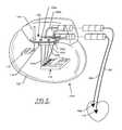
- Feedthrough hermetic terminalsare generally well-known in the art for connecting electrical signals through the housing or case of an AIMD such as those illustrated in FIG. 1 .
- a hermetic terminal 100comprises one or more conductive terminal pins 102 a - 102 d supported by an insulative structure for feedthrough passage from the exterior to the interior of an AIMD electromagnetic shield housing 104 .
- Many different insulator structures and related mounting methodsare known in the art for use in AIMDs, wherein the insulative structure also provides a hermetic seal to prevent entry of body fluids into the housing of the AIMD.
- feedthrough terminal pinsare typically connected to one or more implanted leads 106 and 106 ′ are routed from the outside or body fluid side of the AIMD electromagnetic shield housing 104 to cardiac tissues such as those located in a right atrium 108 or in a right ventricle 110 .
- These implanted leads 106undesirably act as an antenna and thus tend to collect stray electromagnetic interference (EMI) signals from the patient environment for conducted transmission into the interior of the AIMD electromagnetic shield housing 104 .
- EMI signalsmay interfere with the proper operation of AIMD electronic circuits.
- the AIMD internal electronic circuitsare located on a circuit board or substrate 112 . Also shown is an RF telemetry pin 114 .
- the circuit board 112 and the telecommunications circuit board 116can be combined into one overall substrate or they may be broken down into several different substrates located within the AIMD electromagnetic shield housing 104 .
- there is a ceramic feedthrough filter capacitor 118which is typical of many prior art devices.
- the hermetic terminal 100has been combined directly with frequency selective components such as the ceramic feedthrough filter capacitor 118 or MLCC chip capacitors or the like (not shown), to decouple or divert interfering signals from the point of lead ingress to the shielded housing of the AIMD.
- frequency selective componentssuch as the ceramic feedthrough filter capacitor 118 or MLCC chip capacitors or the like (not shown)
- Examples of mounting MLCC chip capacitors to the hermetic terminals of AIMDsare more thoroughly described in U.S. Pat. Nos. 5,650,759 and 5,896,267, the contents of which are incorporated herein by reference. It is very important to decouple these signals at their point of ingress to the electromagnetically shielded AIMD so that such stray signals do not re-radiate or couple to sensitive circuits inside the AIMD electromagnetic shield housing 102 .
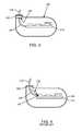
- FIG. 3is an example of good practice in the mounting of a prior art broadband EMI filter 120 such as the ceramic feedthrough capacitor 118 .
- the broadband EMI filter 120has been mounted directly to or adjacent to the hermetic terminal 100 at the point of ingress of an implanted lead 122 .
- a leadwire 124 routed inside the AIMD electromagnetic shield housing 104are free of high frequency EMI signals. Accordingly, the leadwires 124 cannot reradiate or couple undesirably to internal circuit board 112 electronic components.
- FIG. 4is an example of prior art poor practice. In this case, the onboard EMI filter components have been mounted on the internal circuit board 112 inside of the AIMD electromagnetic shield housing 104 .
- the AIMD electromagnetic shield housing 104is typically made of titanium, stainless steel, or other suitable biocompatible material which creates an equipotential shield housing. Seams are uniformly laser welded so that there are no openings.
- An alternativeis use of a ceramic, plastic or composite housing with an electromagnetic shield coating disposed on either its interior and/or exterior surfaces.
- the AIMD electromagnetic shield housing 104may also be coated with nano materials that form an RF shield.
- the AIMD electromagnetic shield housing 104provides hermeticity to protect the sensitive electronic circuits from the intrusion of body fluids.
- the AIMD electromagnetic shield housing 104both reflects and absorbs incident electromagnetic waves.
- the AIMD electromagnetic shield housing 104also forms a very convenient equipotential surface to which high frequency EMI signals conducted from the implanted leads 122 may be decoupled/diverted. This is typically done using passive or active filter elements which can be mounted directly on or adjacent to the point of AIMD housing implanted lead 122 ingress. In the prior art, the optimal location is to place such bypass (lowpass) filters on or adjacent to the hermetic feedthrough pin terminal.
- the ceramic feedthrough filter capacitors 118are typically mounted on the hermetic terminal 100 and provide a low impedance at high frequencies from the leadwires 124 to the AIMD electromagnetic shield housing 104 , thereby shorting or diverting high frequency EMI signals to the housing 104 .
- the high frequency EMI energyis diverted to the AIMD electromagnetic shield housing 104 , it simply circulates as eddy currents resulting in a few milliwatts of insignificant power dissipation as a small amount of heat. This results in a miniscule and insignificant temperature rise of the AIMD electromagnetic shield housing 104 .
- FIG. 5is an illustration of the attempt by Intermedics to place an MLCC chip capacitor 128 on a flex cable 130 located within the AIMD electromagnetic shield housing 104 .
- the flex cable 130was unshielded but could have a ground circuit trace 132 . It also has an active circuit trace 134 .
- the MLCC chip capacitor 128was located between a pair of electrical connections 136 a , 136 b between the ground circuit trace 132 and the active circuit trace 134 . Unfortunately, this created an inductive loop 136 which very effectively reradiated EMI inside the AIMD electromagnetic shield housing 104 .
- leadwhich is synonymous with implanted lead, shall mean the lead or leads that are routed from the exterior of the AIMD electromagnetic shield housing 104 into body tissues.
- leadwirerefers to wiring, flex cables or circuit traces inside of the AIMD electromagnetic shield housing 104 .
- the term remoteas applied to a circuit board, substrate, capacitor, low pass filter, L-C trap filter, electronic filter, bandstop filter, high voltage suppression array, diode array, and/or short to housing switch network shall mean that any combination of these circuits are mounted remotely relative to the AIMD hermetic seal at or near the distal end of the shielded conduit (usually mounted on an AIMD circuit board or substrate).
- the novel shielded conduitwill both shield the leadwires routed from the AIMD hermetic terminal to the circuit board, remote substrate, capacitor, low pass filter, L-C trap filter, electronic filter, bandstop filter, high voltage suppression array, diode array, and/or short to housing switch network and at the same time also provide a low impedance RF ground return to the overall AIMD electromagnetic shield housing 104 for said remote circuits.
- EMI filtered feedthrough hermetic terminalsare shown and described in U.S. Pat. No. 4,424,551, U.S. Pat. No. 5,333,095, U.S. Pat. No. 5,905,627, U.S. Pat. No. 5,973,906, U.S. Pat. No. 5,959,829, and U.S. Pat. No. 5,759,197, the contents of which are incorporated herein.
- problems associated with low pass EMI feedthrough filters mounted directly to the hermetic terminal 100including increased cost, masking a hermetic seal leaker, and reduced reliability.
- the hermetic terminal subassemblyitself is generally constructed at very high temperature. For example, with a gold brazed alumina hermetic seal subassembly, the gold brazing to the ferrule and terminal pins is done at approximately 800° C. If it is a glass seal composite ceramic subassembly, again very high temperatures are required to re-flow the glass. The subsequent mounting of the EMI filter element is typically done at much lower temperatures. However, when the filter is mounted directly to or against the hermetic terminal subassembly, it is subjected to significant installation stresses.
- the pacemaker manufacturergenerally laser welds the ferrule of the hermetic seal subassembly into the titanium housing of the AIMD. This creates both a thermal shock, thermal rise and mechanical stress which the prior art filter elements must be able to withstand.
- Installation of these filter elements to the hermetic sealtypically involves expensive silver-filled thermal-setting conductive flexible adhesives such as polyimides. In addition to being expensive, these materials are difficult to dispose into the correct positions and require carefully fixturing and cleaning operations. An additional cost comes from the fact that these life-saving devices go through high reliability screening. This includes thermal shock and burn-in of the electronic elements including the low pass filter hermetic seal subassembly. Failure of the electronic filter means that the entire hermetic seal subassembly is also scrap.
- hermetic terminal subassemblyis typically manufactured with biocompatible materials including platinum, platinum iridium pins, gold brazes and the like.
- biocompatible materialsincluding platinum, platinum iridium pins, gold brazes and the like.
- a significant problem in the prior artrelates to the mounting of feedthrough or MLCC capacitors and other types of EMI filters on or adjacent to a hermetic terminal pin/seal subassembly.
- hermetic sealsare very carefully tested after installation into the AIMD housing to ensure that they meet a maximum hermetic seal leak rate. This is generally a 1 ⁇ 10 ⁇ 7 or 1 ⁇ 10 ⁇ 8 cc per second maximum leak rate.
- the mounting of a low pass EMI filter assemblygenerally involves thermal-setting conductive adhesives, epoxies and bonding washers which can mask a leaking hermetic seal.
- U.S. Pat. No. 6,566,978the contents of which are incorporated herein. However, these channels/paths are difficult to manufacture and also add cost.
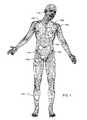
- FIG. 1illustrates various types of active implantable and external medical devices 140 a - 140 i that are currently in use.
- FIG. 1is a wire formed diagram of a generic human body showing a number of implanted medical devices.
- Numeral 140 arepresents a family of hearing devices which can include the group of cochlear implants, piezoelectric sound bridge transducers and the like.
- Numeral 140 brepresents a variety of neurostimulators and brain stimulators.
- Neurostimulatorsare used to stimulate the Vagus nerve, for example, to treat epilepsy, obesity and depression.
- Brain stimulatorsare pacemaker-like devices and include electrodes implanted deep into the brain for sensing the onset of the seizure and also providing electrical stimulation to brain tissue to prevent a seizure from actually occurring.
- Numeral 140 cshows a cardiac pacemaker which is well-known in the art.
- Numeral 140 dincludes the family of left ventricular assist devices (LVAD's), and artificial hearts, including the recently introduced artificial heart known as the Abiocor.
- Numeral 140 eincludes an entire family of drug pumps which can be used for dispensing of insulin, chemotherapy drugs, pain medications and the like. Insulin pumps are evolving from passive devices to ones that have sensors and closed loop systems. That is, real time monitoring of blood sugar levels will occur. These devices tend to be more sensitive to EMI than passive pumps that have no sense circuitry or externally implanted leadwires.
- Numeral 140 fincludes a variety of bone growth stimulators for rapid healing of fractures.
- Numeral 140 gincludes urinary incontinence devices.
- Numeral 140 hincludes the family of pain relief spinal cord stimulators and anti-tremor stimulators.
- Numeral 140 halso includes an entire family of other types of neurostimulators used to block pain.
- Numeral 140 iincludes a family of implantable cardioverter defibrillator (ICD) devices and also includes the family of congestive heart failure devices (CHF). This is also known in the art as cardio resynchronization therapy devices, otherwise known as CRT devices.
- ICDimplantable cardioverter defibrillator
- CHFcongestive heart failure devices
- FIG. 6is a prior art unipolar discoidal feedthrough capacitor 142 , which has an active internal electrode plate set 144 and a ground electrode plate set 146 .
- An inside diameter termination surface 148is connected electrically to the active electrode plate set 144 .
- An outside diameter termination surface 150is both solderable and electrically conductive, and it is connected to the ground electrode plate set 146 .
- FIG. 7is a cross-section of the unipolar discoidal feedthrough capacitor 142 of FIG. 6 shown mounted to a feedthrough hermetic terminal 152 of an active implantable medical device (AIMD).
- AIMDactive implantable medical device
- the leadwire 124is continuous.
- the feedthrough hermetic terminal 152is attached to, typically, a titanium housing 154 , for example, of a cardiac pacemaker.
- An insulator 156like alumina ceramic or glass, is disposed within the ferrule 138 and forms a hermetic seal against body fluids.
- the leadwire 124extends through the feedthrough hermetic terminal 152 , passing through aligned passageways through the insulator 156 and the unipolar discoidal feedthrough capacitor 142 .
- a gold braze 158forms a hermetic seal joint between the leadwire 124 and the insulator 156 .
- a second gold braze 160forms a hermetic seal joint between the alumina insulator 156 and the ferrule 138 .
- a laser weld 162provides a hermetic seal joint between the ferrule 138 and the titanium housing 154 .
- the unipolar discoidal feedthrough capacitor 142is shown surface mounted in accordance with U.S. Pat. No. 5,333,095, and has an electrical connection 164 between its inside diameter metallization 148 and hence the active electrode plate set 144 and the leadwire 124 .
- Feedthrough capacitorsare very efficient high frequency devices that have minimal series inductance. This allows them to operate as EMI filters over very broad frequency ranges.
- EMIelectromagnetic interference
- Cell phones, microwave ovens and the likehave all been implicated in causing interference with active implantable medical devices. If this interference enters the leadwire 124 at a first terminal 170 ( FIG. 7 ), it is attenuated along its length by the unipolar discoidal feedthrough capacitor 142 .
- the undesirable high frequency EMIhas been cleaned off of the normal low frequency circuit current (such as pacemaker pacing pulses or biologic frequency sensors) so that the high frequency EMI has been significantly attenuated.
- the high frequency energypasses from the first terminal 170 to a second terminal 172 ( FIGS. 7 and 8 ), it is diverted through the unipolar discoidal feedthrough capacitor 142 to a ground terminal 174 which is also known as the third terminal or terminal 3 .
- the ground terminal 174is the connection to the overall electromagnetically shielded housing of the AIMD.
- the unipolar discoidal feedthrough capacitor 142 of FIGS. 6-8diverts unwanted high frequency EMI signals from the leadwire 124 to the AIMD electromagnetic shield housing 104 of the AIMD where it dissipates as a few milliwatts of harmless thermal energy.
- the unipolar discoidal feedthrough capacitor 142also performs two other important functions: (a) the internal active electrodes 144 and the internal ground electrodes 146 act as a continuous part of the overall electromagnetic shield housing of the electronic device or module which physically blocks direct entry of high frequency RF energy through the feedthrough hermetic terminal 152 or equivalent opening for leadwire ingress and egress in the otherwise completely shielded housing (such RF energy, if it does penetrate inside the shielded housing can couple to and interfere with sensitive electronic circuitry), and; (b) the unipolar discoidal feedthrough capacitor 142 very effectively shunts undesired high frequency EMI signals off of the leadwires 124 to the overall shield housing where such energy is dissipated in eddy currents resulting in a very small temperature rise.
- FIG. 8is a schematic diagram showing the unipolar discoidal feedthrough capacitor 142 previously described in connection with FIGS. 6 and 7 . As one can see, it is a three-terminal device consistent with the first terminal 170 , the second terminal 172 and the ground terminal 174 illustrated in FIG. 7 .
- FIG. 9is a quadpolar prior art feedthrough capacitor 176 which is similar in construction to that previously described in FIG. 6 except that it has four through holes.
- FIG. 10is a cross-section showing the internal active electrodes 144 and ground electrodes 146 of the quadpolar feedthrough capacitor 176 of FIG. 9 .
- FIG. 11is a schematic diagram showing the four discrete feedthrough capacitors comprising the quadpolar feedthrough capacitor 176 of FIGS. 9 and 10 .
- FIG. 12is an exploded electrode view showing the inner and outer diameter electrodes of the unipolar discoidal feedthrough capacitor 142 of FIGS. 6 and 7 .
- a cover layer 178is put on the top and bottom for added electrical installation and mechanical strength.
- FIG. 13is an exploded view of the interior electrodes of the prior art quadpolar feedthrough capacitor 176 of FIG. 9 .
- the active electrode plate setsare shown as 144 and the ground electrode plates are shown as 146 .
- the cover layers 178serve the same purpose as previously described in connection with FIG. 12 .
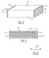
- FIG. 14is a prior art monolithic ceramic capacitor (MLCC) 180 .
- MLCCmonolithic ceramic capacitor
- the MLCC 180has a body 182 generally consisting of a high dielectric constant ceramic such as barium titinate. It also has a pair of solderable termination surfaces 184 , 184 ′ at either end. These solderable termination surfaces 184 , 184 ′ provide a convenient way to make a connection to the internal electrode plates 144 , 146 of the MLCC capacitor 180 .
- FIG. 14can also take the shape and characteristics of a number of other types of capacitor technologies, including rectangular, cylindrical, round, tantalum, aluminum electrolytic, stacked film or any other type of capacitor technology.
- FIG. 15is a sectional view taken from section 15 - 15 in FIG. 14 .
- the MCLL 180includes a left hand electrode plate set 186 and a right hand electrode plate set 188 .
- the opposite, right hand electrode plate set 188is shown connected to the external metallization surface 184 ′.
- Prior art MLCC 180 and equivalent chip capacitorsare also known as two-terminal capacitors. That is, there are only two ways electrical energy can connect to the body of the capacitor. In FIGS. 14 and 15 , the first terminal 170 is on the left side and the second terminal 172 is on the right side.
- FIG. 16is the schematic diagram of the MLCC chip capacitor 180 illustrated in FIGS. 14 and 15 .
- FIG. 17is a different type of prior art MLCC feedthrough capacitor 180 that is built into a special configuration known in the art by some as a flat-through capacitor 190 .
- the flat-through capacitor 190exhibits ideal capacitance behavior versus frequency. That is, its attenuation curve versus frequency is nearly ideal. This is because it is truly a three-terminal device which acts as a transmission line in a manner similar to those of prior art unipolar discoidal feedthrough capacitors 142 . This is better understood by referring to its internal electrode plate geometry as shown in FIG. 18 , wherein a through or active electrode plate 144 is sandwiched between two ground electrode plates 146 , 146 ′.
- the through or active electrode plate 144is connected at both ends by termination surfaces 184 and 184 ′.
- the flat-through capacitor 190When the flat-through capacitor 190 is mounted between the circuit trace lands 192 and 192 ′ as shown in FIG. 17 , this connects the circuit trace together between points 192 and 192 ′. Referring to the active electrode plate 144 in FIG. 18 , one can see the current 168 entering. If this is a high frequency EMI current, it will be attenuated along its length by the capacitance of the flat-through capacitor 190 and emerge as a much smaller in amplitude EMI signal at the second terminal 172 as 168 ′. Similar to the unipolar discoidal feedthrough capacitor 142 , the flat-through capacitor 190 is also a three-terminal capacitor as illustrated in FIG.
- any RF currents that are flowing down the circuit trace lands 192must pass through the active electrode plate 144 of the flathrough capacitor 190 . This means that any RF signals are exposed for the full length of the active electrode plate 144 between the ground electrode plates 146 , 146 ′ and the capacitance that is formed between them. This has the effect of making a very novel shape for a three-terminal feedthrough capacitor.
- One negative to this type of flat-through capacitor 190is that it is not conveniently mountable in such a way that it becomes an integral part of an overall shield.
- Monolithic ceramic manufacturing limitations on electrode thickness and conductivitymeans that the prior art flat-through capacitors 190 have relatively high series resistance and can only be rated to a few hundred milliamps or a few amps at best (however, an implantable defibrillator must deliver a high voltage pulse of over 20-amps).
- Prior art MLCC and flat-through electrodesmust be kept relatively thin to promote ceramic grain growth through the electrodes in order to keep the capacitor layers from delaminating during manufacturing or worse yet, during subsequent mechanical or thermal shocks which can cause latent failures.
- FIG. 19is a schematic diagram of the prior art flat-through capacitor 190 shown in FIG. 17 . Note that this schematic diagram is the same as that for the unipolar discoidal feedthrough capacitor 142 shown in FIGS. 6 and 7 . The difference is that the unipolar discoidal feedthrough capacitor 142 is inherently configured to be mounted as an integral part of an overall shield which precludes the problem of the RF coupling 194 (see FIGS. 9-11 ).
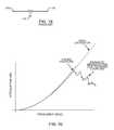
- FIG. 20illustrates the attenuation versus frequency response curve which is shown generically for the flat-through capacitor 192 of FIG. 17 . If it were not for cross-coupling of RF energy, it would perform as an ideal or nearly perfect capacitor. However, because of this cross-coupling, there is always going to be a certain frequency at which the attenuation starts to parasitically drop off as shown. This drop off is very undesirable in active implantable medical device (AIMD) applications in that there would be less protection against high frequency EMI emitters such as cellular phones and the like.
- AIMDactive implantable medical device
- an EMI shielded conduit assemblyfor an active implantable medical device, and a related method of remotely mounting the low pass EMI filter or other electronic component or assembly at a location remote from the hermetic terminal subassembly.
- this mountingwould be either at or near the circuit board or substrate where automated low cost electronic assembly methods could be used.
- a shielded conduitwhich has the effect of extending the overall electromagnetic shield (titanium housing) to a remote location at the location of the low pass filter.
- the shieldshould extend all the way to the low pass filter elements such that no coupling or re-radiation inside of the device can occur.
- the present inventionfulfills these needs and provides other benefits.
- An EMI shielded conduit assembly for an active implantable medical deviceincludes an EMI shield housing for the AIMD, a hermetic feedthrough terminal associated with the AIMD housing, an electronic circuit board, substrate or network disposed within the AIMD housing remote from the hermetic feedthrough terminal, at least one leadwire extending from the hermetic feedthrough terminal to the remote electronic circuit board, substrate or network and an EMI shield conductively coupled to the AIMD housing and substantially co-extending about the leadwire in non-conductive relation thereto.
- the EMI shielded conduit assemblymay include a plurality of leadwires extending from the hermetic feedthrough terminal to the remote electronic circuit board, substrate or network.
- a non-conductive insulatormay be disposed between each leadwire and its respective EMI shield.
- the EMI shieldmay include multiple EMI shields conductively coupled to the AIMD housing and each co-extensively extending about at least one respective leadwire in non-conductive relation thereto.
- the electronic circuit board, substrate or networkpreferably includes a low pass EMI filter, an L-C trap, a bandstop filter, a programmable short-to-housing switch network, or a combination thereof.
- the low pass EMI filtermay include a capacitor, a feedthrough capacitor, an MLCC chip capacitor, a flat-through capacitor, an X2Y attenuator, a multi-element low-pass filter, an active electronic filter, or a combination thereof.
- the low pass EMI filter and the L-C trapmay be grounded to the EMI shield.
- the low pass filter, the L-C trap, or the bandstop filtermay be disposed on the circuit board or the substrate.
- the EMI shieldextends from the hermetic feedthrough terminal to the low pass EMI filter, the L-C trap, or the bandstop filter.
- the EMI shielded conduit assemblymay further include a high voltage suppression network associated with the remote electronic circuit board, substrate or network.
- the high voltage suppression networkis preferably grounded to the EMI shield.
- the high voltage suppression networkincludes a diode array.
- the EMI shielditself preferably includes a conductive heat-shrink tubing, a conductive foil, wire, braid, mesh, circuit trace, or solid tubular material.
- the EMI shieldis preferably radially spaced from the leadwires and may include a flex cable embodying at least one of the leadwires and the EMI shield.
- the hermetic feedthrough terminalmay include a ferrule conductively coupled to the AIMD housing.
- the EMI shieldis preferably conductively coupled to the ferrule.
- the AIMD housingmay further include a conductive equipotential surface, such as a metallic can.
- FIG. 1is a wire-form diagram of a generic human body showing a number of exemplary active implantable medical devices (AIMD);
- AIMDactive implantable medical devices
- FIG. 2is an illustration of a human heart and a sample cardiac pacemaker having implantable leads implanted in the right atrium or right ventricular of the heart;
- FIG. 3is a sectional view of an AIMD housing having the EMI filter mounted directly to the hermetic terminal at the point of ingress of the implantable leadwires;
- FIG. 4is a sectional view similar to FIG. 3 , of an AIMD housing having an onboard EMI filter on the internal circuit board such that EMI signals re-radiate from internal leadwires to the internal circuit board;
- FIG. 5illustrates an MLCC chip capacitor on a flex cable located within the AIMD housing
- FIG. 6is a fragmented perspective view of a prior art unipolar discoidal feedthrough capacitor
- FIG. 7is a cross-sectional view of the feedthrough capacitor of FIG. 6 , taken about the line 7 - 7 , shown mounted to a hermetic terminal of an AIMD;
- FIG. 8is an electrical schematic diagram of the feedthrough capacitor of FIGS. 6 and 7 ;
- FIG. 9is a perspective view of a quadpolar feedthrough capacitor
- FIG. 10is a cross-sectional view of the quadpolar feedthrough capacitor, taken along the line 10 - 10 of FIG. 9 ;
- FIG. 11is an electrical schematic diagram of the quadpolar feedthrough capacitor of FIGS. 9 and 10 ;
- FIG. 12is an exploded perspective view illustrating the electrode lay-ups of the unipolar feedthrough capacitor of FIGS. 6 and 7 ;
- FIG. 13is an exploded perspective view illustrating the electrode lay-ups of the quadpolar feedthrough capacitor shown in FIGS. 9 and 10 ;
- FIG. 14is a perspective view of a monolithic ceramic capacitor (MLCC).
- MLCCmonolithic ceramic capacitor
- FIG. 15is a cross-sectional view of the monolithic ceramic capacitor, taken along the line 15 - 15 of FIG. 14 ;
- FIG. 16is an electrical schematic diagram of an ideal MLCC capacitor as illustrated in FIGS. 14 and 15 ;
- FIG. 17is a perspective view of a prior art flat-through capacitor
- FIG. 18illustrates the internal electrode array of the flat-through capacitor of FIG. 17 ;
- FIG. 19is an electrical schematic drawing of the prior art flat-through capacitor of FIGS. 17 and 18 ;
- FIG. 20is a graph illustrating the attenuation verses frequency response of the flat-through capacitor of FIGS. 17 and 18 ;
- FIG. 21is a fragmented and partially sectional view of an EMI shielded conduit assembly for an AIMD, in accordance with the present invention.
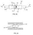
- FIG. 22is an end view of the EMI shielded conduit assembly taken generally from the line 22 - 22 of FIG. 21 ;
- FIG. 23is an enlarged view of a circuit junction, taken of the area indicated by the reference number 23 in FIG. 21 ;
- FIG. 24is an enlarged cross-sectional view of the circuit junction, taken along the line 24 - 24 of FIG. 23 ;
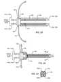
- FIG. 25is a sectional view similar to FIG. 21 , except that the shielded conduit is replaced by a conductive heat-shrink tubing;
- FIG. 26illustrates the heat-shrink tubing shrunk around four leadwires
- FIG. 27is an end sectional view taken generally along the line 27 - 27 of FIG. 26 , illustrating the four leadwires within the shrunk heat-shrink tubing;
- FIG. 28is an electrical schematic diagram of the EMI shielded conduit assembly shown in FIGS. 21-27 ;
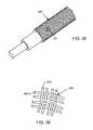
- FIG. 29is a fragmented perspective view of a particular type of EMI shield having a braid shielding
- FIG. 30is an end view of an EMI shield having an insulation material disposed between the leadwire and the EMI shield conduit;
- FIG. 31is an elevational view of the solid copper EMI shield conduit of FIG. 30 ;
- FIG. 32is a fragmented perspective view of a coaxial wound wire forming an EMI shield conduit
- FIG. 34is a perspective view similar to FIG. 33 , further illustrating multiple leadwires disposed within the insulation material surrounded by the conductive foil;
- FIG. 35is fragmented perspective view of an EMI shielded conduit formed from a shielded mesh interwoven with conductive strands;
- FIG. 36is an enlarged view of the shielded mesh interwoven with the conductive strands, taken about the area designated by reference number 36 in FIG. 35 ;
- FIG. 37is a fragmented perspective view of an EMI shield conduit mounted to a circuit board having multiple MLCC chip capacitors;
- FIG. 38is an electrical schematic diagram of the remote MLCC mounted filter illustrated in FIG. 37 ;
- FIG. 39is a perspective view of a multi-element chip capacitor monolithic array that may be used in place of the four separate MLCC capacitors shown in FIG. 37 ;
- FIG. 40shows the internal active electrodes (AE) of the multi-element chip capacitor monolithic array of FIG. 39 ;
- FIG. 42is a circuit diagram illustrating an embodiment wherein the EMI shield conduit has no low pass filter
- FIG. 44is a circuit diagram illustrating an L section low pass filter including an inductor and a capacitor
- FIG. 45is a circuit diagram illustrating a reverse low pass filter where the capacitor points toward the hermetic seal
- FIG. 46is a circuit diagram illustrating a T filter
- FIG. 47is a circuit diagram illustrating a PI filter
- FIG. 48is a circuit diagram illustrating an n-element low pass filter
- FIG. 51is a circuit diagram illustrating the combination of a low pass filter, a bandstop filter and an L-C trap filter
- FIG. 52is a circuit diagram illustrating the combination of an L-C trap filter, a bandstop filter, an LP filter, a second bandstop filter and a second L-C trap filter;
- FIG. 53is a circuit diagram illustrating an automatic or programmable electronic short-to-housing switch network chip or electronic switch array
- FIG. 54illustrates a prior art connection of a flex cable to leadwires that pass through hermetic terminal in non-conductive relationship
- FIG. 55is a cross-sectional view of an improved flex cable embodying the present invention.
- FIG. 56is a perspective view of the flex cable of FIG. 55 connected to a circuit board or substrate having a flat-through capacitor;
- FIG. 57illustrates the lay-up of the active electrode plate set (AEP) for the flat-through capacitor of FIG. 56 ;
- FIG. 58illustrates the lay-up of the ground electrode plate (GEP) of the flat-through capacitor of FIG. 56 ;
- FIG. 59is a sectional view taken along line 59 - 59 of FIG. 55 ;
- FIG. 60is a sectional view taken along line 60 - 60 of FIG. 55 , illustrating one of a pair of coaxially surrounding shields disposed about the circuit trace;
- FIG. 61is a sectional view taken along the line 61 - 61 of FIG. 55 , illustrating an alternative to the internal circuit traces described with respect to FIG. 59 ;
- FIG. 62illustrates the bottom shield ground of the flex cable of FIGS. 55 and 56 ;
- FIG. 63is a cross-sectional view of the hermetic seal assembly taken along the line 63 - 63 of FIG. 55 ;
- FIG. 64is a perspective view of an attachment cap used to connect a shielded flat-through EMI filter to various types of hermetic or non-hermetic seals;
- FIG. 65is a cross-sectional view of a hermetic terminal including the cap of FIG. 64 ;
- FIG. 66is a cross-sectional view illustrating a hermetic terminal assembly embodying the present invention.
- FIG. 67is an enlarged perspective view of a cap assembly, taken generally of the area indicated by line 67 - 67 of FIG. 66 ;
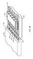
- FIG. 68is a perspective view of a cylindrical or coaxial shielded conduit attached to a stamped or machine metallic lid cover to shield an inline octa-polar assembly;
- FIG. 69is a diagrammatic view of the full length of the EMI shielded conduit of FIG. 68 ;
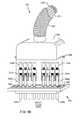
- FIG. 70is a partially exploded perspective view of a shield conduit and cover spaced from a feedthrough capacitor
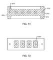
- FIG. 71illustrates internal ground electrode plates (GEP) of the feedthrough capacitor of FIG. 70 ;
- FIG. 72illustrates internal active electrode plates (AEP) of the feedthrough capacitor of FIG. 70 ;
- FIG. 73is a perspective view illustrating a flat-through capacitor mounted to a shield plate designed to be soldered to a cover assembly
- FIG. 74illustrates the lay-up of the active electrode plates (AEP) of the flat-through capacitor of FIG. 73 ;
- FIG. 75illustrates a ground electrode plate (GEP) of the flat-through capacitor of FIG. 73 ;
- FIG. 76is a schematic illustrating an alternative embodiment of a flat-through capacitor electrically and mechanically connected directly to the inside of a surface of the cover assembly;
- FIG. 77is an end view of the feedthrough capacitor, taken from the perspective of arrow 77 of FIG. 76 ;
- FIG. 78illustrates the active electrode plates (AEP) of the flat-through capacitor of FIG. 76 ;
- FIG. 79illustrates the ground electrode plate (GEP) of the flat-through capacitor of FIG. 76 .
- the EMI shielded conduit assembly for an active implantable medical devicecomprises: (1) an EMI shielded housing for the AIMD; (2) a hermetic feedthrough terminal associated with the AIMD housing; (3) an electronic circuit board, substrate or network disposed within the AIMD housing remote from the hermetic feedthrough terminal; (4) at least one leadwire extending from the hermetic feedthrough terminal to the remote electronic circuit board, substrate or network; and (5) an EMI shield conductively coupled to the AIMD housing and co-extensively extending about the at least one leadwire in non-conductive relation.
- functionally equivalent components of various embodimentswill be referred to by the same reference numbers or letters.
- FIG. 21illustrates the basic components of an EMI shielded conduit assembly 196 for an active implantable medical device (AIMD) as outlined above.
- the conductive ferrule 138 of a hermetic seal 198is generally of titanium, platinum, or similar biocompatible metal.
- the laser weld 162hermetically seals the AIMD electromagnetic housing 104 .
- the hermetic seal 198embodies a set of terminal pins 200 a - 200 d attached to the implanted leads 122 a - 122 d , which the terminal pins 200 a - 200 d pass through in non-conductive relation.
- the hermetic seal 198typically comprises an alumina ceramic or glass insulator (not shown). It is important that the metallic ferrule 138 be an electrically continuous part of the overall AIMD electromagnetic shield housing 104 .
- the novel EMI shielded conduit assembly 196connects electrically to the ferrule 138 of the hermetic terminal seal 198 . If there is no ferrule present, the EMI shielded conduit assembly 196 may be electrically connected directly to the AIMD electromagnetic shield housing 104 . This conductive EMI shielded conduit assembly 196 extends down to an AIMD electronic circuit board, substrate or network 202 . In a preferred embodiment, there are a set of conductive support tabs or feet 204 which are electrically connected to an EMI shield 206 . As will be further described, the EMI shield 206 can be continuous solid (flexible) tubing, a shield braid, shielded wires, shielded foil, shielded mesh or even conductive circuit traces within a flex cable.
- this EMI shield 206at least partially co-extensively surround the AIMD internal leadwires 124 a - 124 d .
- the implanted leads 122 a - 122 dare routed endocardially to cardiac chambers. These implanted leads 122 a - 122 d can also undesirably act as antennas which can pick up stray and unwanted EMI.
- One purpose of the conductive conduit or the EMI shield 206is to prevent re-radiation of the EMI inside the AIMD electromagnetic shield housing 104 before it reaches the electronic circuit board, substrate or network 202 at location 208 .
- a filter capacitor component 210is shown as an integral part of the overall EMI shielded conduit assembly 196 . As will be shown in subsequent drawings, it can be eliminated, it can be placed on the circuit board 202 or consist of alternate components.
- the EMI filterin this case, is a quadpolar low pass filter consisting of the filter capacitor component 210 . This is identical to the prior art quadpolar feedthrough capacitor 176 shown in FIGS. 9-11 and 13 .
- the conductive support feet 204are electrically connected to the EMI shield 206 and are also connected to a set of ground circuit traces 212 a - 212 b on the circuit board 202 .
- the implanted leads 124 a - 124 d and the hermetic terminal pins 200 a - 200 dare exposed to body fluids and have to be of suitable biocompatible materials, such as platinum, platinum-iridium, niobium, palladium and the like.
- a circuit junction connection 214is shown to make a connection from the hermetic seal terminal pin(s) 200 a - 200 d to the much lower cost leadwires 124 a - 124 d .
- the circuit junction connections 214can be a simple solder joint, a crimp or twist connector as illustrated, a plug-in pin, or any other method of joining two leadwires together.
- FIG. 23is a blown-up view of the circuit junction connection 214 of FIG. 21 .
- Shownis a novel crimp connection 216 .
- the crimp connection 216has a crimp 218 to the hermetic terminal pin 200 a and also includes a crimp 218 ′ to the leadwire 124 a .
- An optional hole 220has been provided for convenient soldering or laser welding of an exposed leadwire end 222 .
- the leadwire 124 awould be of stranded insulated wire. One can see that the insulation has been removed by the leadwire end 222 so that it will contact soldering, the crimp 218 , the laser weld 162 , and a braze or thermal-setting conductive adhesive material 224 .
- FIG. 24is a cross-section taken generally from section 24 - 24 from FIG. 23 .
- the cross-sectionis shown prior to crimping and shows that the hole 220 need not be round.
- a hole 220 ′ in FIG. 24is oval, but could also be elliptical, or any other shape.
- Also shownare a pair of optional internal indents 226 which are convenient when one places the terminal pin 200 a and the leadwire 124 a into place. The indents 226 stop the leadwire from pushing in too far so it can be properly located for crimping.
- Circuit junction connection 214can be eliminated if the wires coming out of the hermetic seal 198 are made sufficiently long enough.
- insulation tubing(not shown) would be placed over each of the leadwires 124 a - 124 d (which in this case, become the same as the terminal pins 200 a - 200 d ).
- Said tubingcould also be non-conductive heat-shrink tubing.
- the EMI shield 206could be slipped over the leadwires and then electrically connected to the AIMD electromagnetic shield housing 104 or to the conductive ferrule 138 of the hermetic seal 198 .
- the filter capacitor component 210 of FIG. 21has its outside diameter termination or metallization surface 150 ( FIGS. 6 and 9 ) electrically and mechanically attached to the EMI shield 206 . This provides a solid low impedance RF ground. Accordingly, the EMI shielded conduit assembly 196 becomes an extension of the overall electromagnetic shield of the AIMD electromagnetic shield housing 104 .
- the EMI shielded conduit assembly 196could also be formed from low cost conductive (shielded) heat-shrink tubing.
- the heat-shrink tubingwould be heated to cause it to simultaneously be shrunk down over the four insulated leadwires 124 a - 124 d , and at the same time be shrunk down around the outside diameter or perimeter of the ferrule 138 of the hermetic seal 198 to form the ground connection to the AIMD electromagnetic shield housing 104 . It is very important that the overall coaxial or co-extensive EMI shield 206 be circumferentially and longitudinally nearly continuous and of very low inductance so that the EMI filter capacitor component 210 can provide proper attenuation at high frequencies.
- the support feet 204can alternatively be non-conductive, in which case they are simply there to provide mechanical attachment and resistance to shock and vibration loads. Or, as shown, the support feet 204 can be conductive and connect to the ground circuit traces 212 a and 212 b .
- the ground circuit traces 212 a and 212 bare very useful for AIMD circuitry. For example, this low impedance ground can be used for connection of high voltage suppression arrays, such as diode arrays. As will be further illustrated, these ground circuit traces 212 a and 212 b are very useful to ground in or on an electronic circuit board, substrate or network.
- the ground circuit traces 212 a and 212 bare also very useful for combinations of bandstop filters, L-C trap filters, low pass filters, electronic filters, a short-to-housing switch network, and the like. They could also be used for reference grounding or grounding of telemetry circuits and the like.
- the EMI shield conduitin addition to shielding of the leadwires, also provides a low impedance circuit path for RF grounding of the remote EMI filter and/or other AIMD circuits.
- FIG. 22is an end view taken generally from section 22 - 22 from FIG. 21 . Shown are the end views of the leadwires 124 a - 124 d as they exit the filter capacitor component 210 . One can also see the support feet 206 connected to the ground circuit traces 212 a and 212 b of the circuit board 202 ( FIG. 21 ). In the case of a cardiac pacemaker, the circuit board 202 would also be known as the pacer hybrid board which contains various electronic modules, microelectronic chips, cardiac sense circuits and so on. Also shown are alternative via holes 228 a - 228 d which connect to the leadwires 124 a - 124 d . These can go to external or the interior circuit traces 230 a - 230 d of the multilayer circuit board 202 .
- FIG. 25is very similar to the left side of FIG. 21 except that the novel EMI shielded conduit assembly 196 has been replaced by a conductive heat-shrink tubing 232 .
- a non-conductive heat-shrink insulation tubing 234is slipped down over the leadwires 124 a - 124 d as shown.
- the insulation tubing 234does not have to be heat-shrink tubing in this case. It could be a thin wall slip-on insulation tubing, such as Kapton or the like. Since the conductive ferrule 138 of the hermetic seal 198 is typically of titanium, it is prone to formation of oxides. These oxides can degrade electrical connections.
- FIG. 26is the same view as FIG. 25 after heat has been applied to shrink the conductive heat-shrink tubing 232 .
- FIG. 27is an end view taken generally from section 27 - 27 from FIG. 26 . It shows the end view of the four leadwires 124 a - 124 d.
- FIG. 28is a functional schematic diagram of the novel shielded conduit remote filter as previously discussed in FIGS. 21 through 27 .
- there are four capacitors 238 a - 238 dwhich are integral to the monolithic quadpolar feedthrough capacitor 176 illustrated in FIGS. 9-11 and 13 .
- the capacitors 238 a - 238 dmay be eliminated in certain AIMD designs where the AIMD internal unshielded leadwires or circuit traces are short in length compared to the wavelength of the EMI signals. In this case, the feedthrough capacitor would be eliminated and just the shielded conduit would be routed to the circuit board 202 as shown. This approach is particularly applicable to AIMDs that do not have sense circuits such as many implantable neurostimulators.
- AIMDs that do not have biologic sense circuitsare inherently less sensitive to EMI.
- the leadwires 124 a - 124 d illustrated in FIG. 28are shown connected to the AIMD electronic circuit board, substrate or network 202 which can include a variety of electronic circuits including microchips.
- the purpose of the quadpolar feedthrough capacitor 176is to provide a single element low pass filter to ground on each leadwire 124 a - 124 d in order to protect the sensitive electronics on the circuit board 202 from EMI that can be coupled from the implanted leads 122 a - 122 d . This is particularly important if the AIMD electronic circuit board, substrate or network 202 has biologic sensing circuits which is common in the prior art for cardiac pacemakers and ICDs.
- FIG. 29illustrates a particular type of EMI shield 206 called braid shielding.
- a set of fine wires 240are woven back and forth underneath an insulated surface 242 (transparent) as shown.
- FIGS. 30 and 31show that the novel EMI shielded conduit assembly 196 can be of solid material such as soft copper.
- FIG. 30is an end view illustrating the solid tubing of the EMI shielded conduit assembly 196 and the unipolar leadwire 124 disposed within an insulative material 244 .
- the insulative or dielectric material 244is used as shown.
- FIG. 32illustrates the use of a coaxial wound wire 246 to form the EMI shield 206 .
- FIG. 33shows the use of a metallic thin conductive foil, or foils, 248 which can be formed, wound, or woven around the insulative material 244 to form the EMI shield 206 around the leadwire 124 .
- FIG. 34is very similar to FIG. 30 , but shows four leadwires 124 a - 124 d.
- FIG. 35illustrates a shielded mesh 250 interwoven with a set of conductive strands 252 ( FIG. 76 ).
- FIG. 36is an enlarged view of area 36 in FIG. 35 showing how the conductive strands 252 , 252 ′ are woven. It is very important that the weaving be fairly tight so stray high frequency EMI cannot penetrate the shield and that the inductance of the shield conduit be relatively low.
- FIG. 37shows an alternative embodiment of the EMI shielded conduit assembly 196 that was previously shown in FIG. 21 .
- the filter capacitor component 210 that was shown in FIG. 21could still be used, but it would be mounted on the circuit board 202 in place of the four MLCC chip capacitors 128 a - 128 d shown in FIG. 37 .
- the filter capacitor component 210would ideally be mounted face down on the circuit board 202 with its outside diameter ground metallization 150 ( FIG. 9 ) electrically attached to a surrounding ground plane 254 which is also connected to the proximal end of the EMI shielded conduit assembly 196 .
- the leadwires 124 a - 124 dare routed within the overall EMI shielded conduit assembly 196 to the left hand side of the prior art MLCC chip capacitors 128 a - 128 d .
- the conductive support foot assembly 204is shown electrically and mechanically connected to a ground plane 254 .
- This ground plane 254is desirably wide and continuous so it will form an effective low impedance high frequency equipotential surface.
- the right hand side of the prior art MLCC chip capacitors 128 a - 128 dare electrically connected to this ground plane 254 .
- the ground plane circuit trace 254is electrically connected to the EMI shielded conduit assembly 196 . It is very important that this circuit path be very low in impedance. That is, it is important that at high frequency, the surface of the ground plane 254 be held at approximately the same potential as the overall AIMD electromagnetic shield housing 104 . To accomplish this, the EMI shielded conduit assembly 196 must be of relatively large cross-sectional area. This can be imagined if one were to slit it and then roll it out flat and look at it from edge view. This forms, in the art, an equivalent RF grounding strap.
- the novel EMI shielded conduit assembly 196forms two very important purposes: (1) it effectively shields and prevents EMI re-radiation inside the AIMD housing from the leadwires 124 a - 124 d ; and (2) it provides a very low impedance connection back to the AIMD electromagnetic shield housing 104 to the circuit board ground path 254 .
- the leadwires 124 a - 124 dare electrically connected through the via holes 228 a - 228 d using an electrical connective material 256 - 256 ′′′, such as solder or thermal-setting conductive adhesive.
- the MLCC capacitors 128 a - 128 dare also electrically connected to the ground plane 254 through electrical connections 256 - 256 ′′′.
- the shielded support foot 204is in the form of a ring and is electrically connected either through holes 258 or by way of an outside electrical connection 260 as shown. It is important that the portion of the leadwires 124 a - 124 d that exits the EMI shielded conduit assembly 196 be kept quite short so they will not become an effective re-radiating antenna or stray capacitance which would allow EMI to couple to sensitive circuits such as pacemaker sense circuits.
- the assemblies shown in FIG. 37are all mounted to the AIMD electronic circuit board, substrate or network 202 which supports other surface mounted or imbedded AIMD electronic components (not shown).
- the via holes 228 a - 228 dconnect to internal circuit traces 230 a - 230 d as shown.
- FIG. 38is a schematic diagram of the remote MLCC chip capacitor 128 as illustrated in FIG. 37 .
- the hermetic terminal 100Its ferrule 138 is coupled to a ground 262 , which is coupled to the overall AIMD electromagnetic shield housing 104 .
- the EMI shielded conduit assembly 196is also shown electrically grounded to the hermetic terminal 100 . It is important that this be a low impedance oxide free connection. This connection from the EMI shielded conduit assembly 196 can be accomplished by a clamp (not shown) which binds the conductive EMI shielded conduit assembly 196 to the outside diameter of the ferrule 138 .
- the titanium ferrule 138 of the hermetic terminal 100would be pretreated with plating, gold braze, or the like to prevent oxidation.
- An alternativewould be to solder, braze or attach with conductive adhesives the EMI shielded conduit assembly 196 to the ferrule gold braze of the hermetic seal assembly (ref. the methods described in U.S. Pat. No. 6,765,779, the contents of which are incorporated herein).
- the remote EMI filter(or optionally an unfiltered circuit board), in this case, consists of the four MLCC chip capacitors 128 a - 128 d as shown. These also form in the art what is known as a quadpolar single element low pass filter.
- inductor element 264has been shown in the leadwire 124 a . It will be obvious to those skilled in the art that additional capacitors and inductors can be added to form L, PI, T, LL or “n” element low pass filters in any or all leadwires 124 a - 124 d . Referring once again to FIG. 38 , one can see that the low pass filter elements are also closely coupled to a high voltage suppression array 266 .
- the high voltage suppression array 266can consist of back-to-back diodes 268 a and 268 b as shown, zener diodes, Transorbs®, and the like.
- the high voltage suppression diodeshave a low impedance connection to a circuit ground 270 so they can be fast acting. This is important to protect against external high voltage events such as electrostatic discharge or automatic external defibrillation (AED) events.
- An important feature of the EMI shielded conduit assembly 196is that it provides the required low impedance circuit path to ground. Referring once again to FIG. 38 , one can see that the MLCC capacitors 128 a - 128 d are all connected to the conduit circuit ground 270 and in a preferred embodiment, the high voltage suppression array 266 is also connected to the same low impedance circuit ground 270 as shown.
- FIG. 39is generally taken from section 39 - 39 in FIG. 37 .
- Shownis a multi-element chip capacitor monolithic array 272 which is better understood by referring to an internal active electrode 274 a - 274 d and an internal ground electrode 276 in FIGS. 40 and 41 .
- the capacitor array 272 of FIG. 39is very similar to prior art MLCC chip capacitors, but the single quadpolar chip is more volumetrically efficient. This is accomplished by placing all four chip capacitors in a single monolithic package.
- the multi-element chip capacitor monolithic array 272 shown in FIG. 39can also be replaced by the flat-through capacitor 190 as shown in FIGS. 17 through 20 , an active electronic filter, or even an X2Y attenuator.
- An X2Y attenuatoris generally a specially configured ceramic chip capacitor with unique internal electrode geometry. Examples of some X2Y attenuators can be found in U.S. Pat. No. 5,909,350; U.S. Pat. No. 6,018,448; U.S. Pat. No. 6,097,581; U.S. Pat. No. 6,157,528; U.S. Pat. No. 6,282,074; U.S. Pat. No. 6,388,856; U.S. Pat. No. 6,373,673; WO2005/1015719; US2004/0027771; US2004/0032304; U.S. Pat. No. 6,469,595; U.S. Pat. No.
- FIGS. 42 to 53show various circuit schematic combinations which illustrate a number of ways that the novel EMI shielded conduit assembly 196 may be configured with remote circuit boards/substrates 202 , low pass filters LP, BSFs, L-C traps, active electronic filters, high voltage suppression (circuit protection) arrays, and electronic short-to-housing switch networks.
- FIGS. 42 to 52are all illustrated for one leadwire 124 or circuit path of the AIMD only.
- the AIMDcan have any number of circuit leadwires 124 that are routed through one or more hermetic seal 198 terminal pins 200 to the implanted leads 122 to which the present invention applies.
- FIG. 42illustrates the case with no passive low pass filter where the circuit traces 212 a to 212 n are short relative to the EMI frequency wavelength and/or the AIMD is not very sensitive to EMI.
- FIG. 43illustrates an inductor 264 single element low pass filter 280 .
- FIG. 44illustrates what is known in the prior art as an “L” section low pass filter 282 consisting of the inductor 264 and the capacitor 238 . In this case, the inductor 264 points toward the hermetic seal (body fluid side).
- FIG. 45is a reverse “L” low pass filter 284 where the capacitor 238 points toward the hermetic seal (body fluid side).
- FIG. 46is known in the art as a “T” filter 286 .
- FIG. 47is known as a PI filter 288 .
- FIG. 48generally shows an n-element low pass filter 290 . Either the inductor ( 264 a as shown) or the capacitor 238 a can be the first component on the hermetic seal (body fluid side).
- FIG. 49illustrates a bandstop filter (BSF) 292 in series with the leadwire 124 consisting of the inductor 264 and the capacitor 238 in parallel (there can also be a resistive element, which is not shown).
- BSFbandstop filter
- FIG. 50illustrates an L-C trap filter 294 .
- the L-C trap filter 294connects from the leadwire 124 to the low impedance circuit ground 262 and consists of the capacitor 238 in series with the inductor 264 (there can also be a resistive element, which is not shown).
- U.S. Pat. No. 6,424,234which is herein incorporated by reference, for a full explanation of L-C trap filter characteristics, resonance equations, bandwidth and impedance vs. frequency curves.
- FIGS. 51 and 52illustrate that any of the low pass filters 280 - 284 and 290 can be wired in various combinations with the BSF filter 292 and/or the L-C trap filter 294 to form any passive filter that one wishes to realize.
- the EMI shielded conduit assembly 196forms the circuit ground 262 for the circuit board 202 , the low pass filter 280 - 284 and 290 , the L-C trap filter 294 , the high voltage suppression array 266 , a telemetry circuit, a general circuit board/substrate reference (this is particularly important when the AIMD housing becomes a pacing or sensing electrode), an active electronic filter circuit, and/or the RF low impedance ground for a short-to-housing switch network. As shown in FIGS. 51 and 52 , combining any of the low pass filters 280 - 284 and 290 with the bandstop filters 292 and/or the L-C trap filters 294 can be very effective for MRI environments.
- FIG. 53illustrates an automatic or programmable electronic short-to-housing switch network chip or electronic switch array which can be a dedicated chip or a portion of the hybrid or microchip of the AIMD which forms many other functions.
- Electronic switches which form a short to the AIMD housingare more fully described in U.S. patent application Ser. No. 12/489,921.
- the electronic switch array 296 of FIG. 53would have its switches normally closed (in FIG. 53 , they are shown in the open position). This allows the AIMD to operate normally, sense biologic signals, and delivery needed therapy such as pacing pulses to body tissue.
- the switchesare shown in FIG.
- the wiper connectionforms a low impedance RF ground which shorts out each one of the leadwires 124 a - 124 d effectively through the EMI shielded conduit assembly 196 to the AIMD electromagnetic shield housing 104 .
- the switches 298 a - 298 dcan have mechanical wipers, however, in the preferred embodiment, these would be any type of electronic switches such as involving P-N junctions well known in the prior art.
- the switcheswould be controlled (programmed) through AIMD programming and telemetry.
- the switchescould also be configured to switch automatically, say in the presence of a powerful magnetic field such as the static B 0 field of an MRI scanner.
- a powerful magnetic fieldsuch as the static B 0 field of an MRI scanner.
- the switch array ESAwould be used when the AIMD and/or its implanted leads are exposed to powerful electromagnetic fields, such as those produced by a clinical MRI scanner.
- AIMD telemetrythe electronic switch array is easily programmed into its MR Conditional Mode prior to the MRI scan.
- This modeswitches the switches 298 a - 298 d in the electronic switch array to the open (shorted position) as shown in FIG. 53 .
- the AIMDcould also be programmed into an quiescent mode wherein it was not trying to sense biologic signals or deliver therapeutic pulses.
- the position of the switches 298 a - 298 d shown in FIG. 53accomplishes two very important things.
- the firstis that the sensitive electronic circuitry (not shown) of the AIMD is disconnected and therefore becomes highly resistant to being influenced by EMI from the MRI scanner (or other high energy EMI source).
- the second major advantageis the shorting of the leadwires 124 to the low impedance EMI shielded conduit (circuit ground). This will pull unwanted induced RF energy out of the implanted leadwires 124 and divert said energy to the large surface area of the AIMD housing. This will greatly help to reduce implanted distal electrode heating at the points of tissue interface.
- Another advantage of the electronic switch array ESA configuration illustrated in FIG. 53is that the induced RF MRI energy that is picked up by the implanted leads 122 is diverted to the AIMD electromagnetic shield housing 104 which is usually not implanted in an area of the human body that is as sensitive to thermal injury.
- the AIMD electromagnetic shield housing 104which is usually not implanted in an area of the human body that is as sensitive to thermal injury.
- a cardiac pacemakera spinal cord stimulator or a deep brain stimulator
- the novel EMI shielded conduit assembly 196works in conjunction with the electronic switch array 296 .
- FIG. 54illustrates a prior art quadpolar hermetic terminal 300 with a conductive ferrule 302 . Shown are four hermetic seal terminal pins 200 - 200 ′′′ and a prior art flex cable 304 with circuit traces 306 a - 306 d that are routed to a circuit board or substrate 202 . This is a prior art attempt to provide EMI filtering through MLCC capacitors 180 a - 180 d . There is a ground connection 308 which grounds the circuit substrate. There are many attempts in the prior art to form an exposed flex cable or leadwire configuration as shown in FIG. 54 . Due to lack of shielding and a high impedance ground path (loop) these attempts result in very poor EMI filter performance of the overall AIMD.
- circuit path of the circuit traces 306 a - 306 dis relatively long compared to the wavelength of most EMI energy. Therefore, these circuit traces 306 a - 306 d become very effective re-radiating antennas. This is called “the genie in the bottle” affect.
- the EMIgets inside the overall AIMD shielded housing, it can cross-couple or re-radiate to adjacent sensitive circuits, such as pacemaker biologic sense circuits.
- Another problem associated with the prior art arrangement shown in FIG. 54arises due to the narrowness of the circuit traces 306 a - 306 d and their relatively long length 310 , which creates substantial inductance and impedance.
- FIG. 55is a cross-sectional view of an improved flex cable 304 ′ incorporating the novel features described herein, and is very similar to FIG. 54 .
- the circuit trace 306has been imbedded between a top shield plane 312 and a bottom shield plane 314 .
- a parasitic capacitanceis desirably formed between the circuit trace 306 and the surrounding ground shield planes 314 , 316 . This aids in high frequency filter attenuation.
- FIG. 55forms an EMI shield extension of the overall AIMD electromagnetic shield housing 104 .
- FIG. 56illustrates the flex cable 304 ′ from FIG. 55 attached to circuit board 202 . Shown is a surface mounted flat-through capacitor 190 ′.
- the flat-through capacitor 190 ′is very similar to the unipolar flat-through capacitor 190 shown in FIGS. 17 and 18 , but is different in that the flat-through capacitor 190 ′ of FIG. 56 has four capacitors with a single ground plane 318 .
- An active electrode plate set (AEP) 318 for the flat-through capacitor 190 ′ of FIG. 56is shown in FIG. 57 .
- a pair of metallization surfaces 320 and 320 ′correlate to those indicated in FIG. 56 .
- a ground electrode plate (GEP) 322is illustrated in FIG. 58 .
- ground electrode plates 318 , 322 of FIGS. 57 and 58these would typically be stacked up and interleaved to achieve the desired effective capacitance area (ECA).
- ECAeffective capacitance area
- the flat-through capacitor 190 ′For the flat-through capacitor 190 ′ to effectively act as a low pass filter, it is important that a set of ground wires 324 coming from the flex cable 304 ′ present a very low impedance to the overall AIMD electromagnetic shield housing 104 . This is best achieved through the wide ground shield plates 326 , 326 ′ as shown in FIG. 60 . Referring to FIG. 60 , one can see that the ground shield plates 326 , 326 ′ are stitched together with a number of conductive via holes 328 as shown. This creates a Faraday cage shield which co-extensively surrounds and shields all of the circuit traces 306 a - 306 d ( FIGS. 59 and 61 ).
- the flat-through capacitor 190 ′can be replaced or used in combination with prior art circuit board electronics, prior art high voltage suppression arrays, X2Y attenuators, other potential low pass filters, active filters and even electronic short-to-housing switch networks.
- FIG. 59is generally taken from section 59 - 59 of FIG. 55 . Shown are the circuit traces 306 a - 306 d.
- FIG. 60is taken from the two layers 60 - 60 of FIG. 55 . Accordingly, the circuit traces 306 a - 306 d are sandwiched between the ground shield plates 326 , 326 ′ top to bottom as illustrated in FIG. 60 .
- the ground shield plates 326 , 326 ′ of FIG. 60serve to effectively shield the imbedded circuit traces 306 a - 306 d from EMI. Further, the ground shield plates 326 , 326 ′ form a very low impedance path from the electronic circuit board, substrate or network 202 back to the AIMD electromagnetic shield housing 104 .
- FIG. 61is generally taken from layer 61 - 61 of FIG. 55 . This is very similar to FIG. 59 except that an edge ground 330 has been provided to further surround circuit traces 306 a - 306 d . There are also a number of via holes 328 as shown in FIGS. 59 and 60 which help to stitch all the ground planes together. This is important so that the overall EMI shielded extension forms a Faraday cage particularly blocking any re-radiation of EMI in the frequencies of interest below 3 GHz.
- FIG. 62illustrates a bottom shield ground electrode plate 332 of the flex cable 304 ′ from FIG. 55 and FIG. 56 .
- a robothas dispensed a circular portion of a thermal-setting conductive material 334 .
- Thisis designed to align precisely with the gold braze 158 of the hermetic terminal 100 of FIG. 63 . Accordingly, the entire left end of the shielded flex cable 304 ′ can be laid down over the hermetic terminal 110 and then the thermal-setting conductive material 334 can be cured in an oven, furnace or other equivalent process. This makes a suitable electrical and mechanical connection to the exposed bottom ground shield electrode plate 332 . Referring back to FIG.
- FIG. 63is a sectional view of the hermetic seal 100 taken along line 63 - 63 from FIG. 55 .
- BGAball grade array
- internal pins 124 ′ and 124 ′′could have headed leads in the location of gold braze GBS (for example, see FIGS. 9 and 10 of U.S. Pat. No. 7,012,192, which is herein incorporated by reference).
- the ball grade array type attachcould be used between the via hole 328 d , which could be filled, and the nail head of the leadwire 124 (not shown).
- FIG. 64illustrates a novel laser weld cap 336 with a cut out section 338 .
- the cut out section 338is formed or cut so the metal laser weld cap 336 can slip down over a narrow section 340 of the end of the flexible portion of the shielded flex cable 304 ′.
- the laser weld cap 336can be a stamped titanium, machined titanium, injection molded titanium or a number of other metals.
- FIG. 65is a combined cross-section taken generally from 63 - 63 of FIG. 55 and also from section 65 - 65 of FIG. 64 .
- the shielded flex cable 304 ′has been modified to accommodate the novel laser weld cap 336 as illustrated in FIG. 64 .
- the laser weld cap 336is slipped down such that it comes into close contact with a flange 342 of the hermetic terminal 100 .
- a continuous or discontinuous laser weld or braze 344is formed as shown. This makes a solid metallurgical and low impedance ground contact to the hermetic flange 342 and to the laser weld cap 336 .
- ground shield plates 326 and 326 ′are external for the purposes of this illustration; however, they could be internal plates as previously illustrated.
- FIG. 66shows a hermetic terminal assembly 100 .
- the hermetic terminal subassembly 100consists of a metallic ferrule 138 which is generally made of titanium.
- the ferrule 138is gold brazed 158 and 158 ′ to the alumina ceramic insulator 156 as shown.
- Gold brazes 158 ′ and 158 ′′form a hermetic seal between the insulator 156 and the leadwires 124 a -124 d .
- an insulating sleeve 352is slipped down over the leadwire 124 into the inside diameter of the protrusion 350 . This is seated against the bottom adjacent to gold braze 158 ′ or 158 ′′.
- the insulating sleeve 352can be a close-fitting semi-flexible insulation sleeve or it can be a non-conductive heat-shrink tubing. In the case of heat-shrink tubing, the sleeve would be placed down as shown and then heat would be applied to shrink it in place firmly against the leadwire 124 .
- the EMI shielded conduit assembly 196would be slipped down over the outside of the protrusion 350 .
- the cap assembly 348would be electroplated or coated so that there are no issues with oxides.
- the cap assembly 348can also be of suitable materials that do not form oxides. It is very important that the conductive coaxial or co-extensive EMI shielded conduit assembly 196 form a low impedance short-to-housing electrical connection to the end cap protrusion 350 .
- the EMI shielded conduit assembly 196would be a conductive heat-shrink tubing and would be slipped down over the protrusion 350 , heat would then be applied so that the tubing 354 is shrunk down and firmly adhered to the protrusion 350 of the cap assembly 348 .
- the heat-shrink tubing 354is shown in its preshrunk condition. Accordingly, there is a gap 356 between the conductive EMI shield and the insulating sleeve 352 . After applying heat, the heat-shrink tubing 354 would shrink down so that it also bonded against the insulating sleeve 352 .
- the cap assembly 348can be attached to the ferrule 138 of the hermetic terminal 100 by laser welding 162 , by soldering to the gold braze 158 , or by using various thermal-setting conductive adhesives that would connect between the cap assembly 348 and the gold braze 158 . In all cases, it is also important that this be an oxide-free connection.
- the novel cap assembly 348 illustrated in FIG. 66enables the leadwires 124 a - 124 d to be routed to different locations inside of the AIMD electromagnetic shield housing 104 . In other words, as illustrated, leads 124 a , 124 b can be routed off to the right and leads 124 c , 124 d can be routed to another location. This is important in modern AIMDs which can have as many as twelve or more leadwires and multiple electronic circuit boards or substrates.
- FIG. 67is taken generally from section 67 - 67 in FIG. 66 .
- FIG. 67illustrates the details of the cap assembly 348 that has a through hole 358 .
- One or more through holes 358can be provided for convenient brazing or laser welding. This would be very useful if the metallic shielding was of the type as previously illustrated in FIG. 32 or 33 . This is also particularly suitable if the EMI shielded conduit assembly 196 is of braided shield wire.
- FIG. 68illustrates a novel application of a cylindrical or coaxial shielded conduit 360 attached to a stamped or machined metallic lid cover 362 .
- the lid cover 362makes a transition from coaxial to rectangular geometry.
- a hermetic terminal assembly 364which is known as an inline octa-polar (8-pin) assembly.
- Leadwires 124in this case, 124 a - 124 h , are attached using a splice or the previously described circuit junction connection 214 . This would be shown eight times attached to the terminal pins 200 .
- the hermetic insulatorhas a set of gold braze pads 366 that are designed to mate with the mounting tabs and holes 368 of lid cover 362 .
- connection to the terminal pins 200is made using the circuit junction connectors 214 , then the lid cover 362 and the EMI shielded conduit assembly 196 along with its associated attached coaxial shielded conduit 360 is pressed down and seated onto the gold braze pads 366 . Then a solder joint, braze or laser weld is made so that the two are electrically and mechanically joined.
- FIG. 69illustrates the full length of the EMI shielded conduit assembly 196 previously described in FIG. 68 . Shown on the left is the stamped lid cover 362 and on the right is the coaxial shielded conduit 360 .
- the EMI shielded conduit assembly 196is electrically and mechanically attached to both the coaxial shielded conduit 360 and the lid cover 362 .
- the assembly shown in FIG. 69can be preassembled and pre-tested such that it is ready for attachment to the hermetic seal 198 and a circuit board 202 (not shown).
- FIG. 70is taken from FIGS. 68 and 69 except that the right-hand lid cover 362 ′ is rectangular.
- the circuit junction connection 214is used to attach to a substrate or even a feedthrough capacitor 370 as shown. After the leadwires 124 pass through the feedthrough capacitor 370 , they are then attached to the circuit traces 212 on the circuit board 202 . Referring to FIG. 70 , one can see a pair of metallization surfaces 372 and 372 ′ on the feedthrough capacitor 370 . These correspond with connections to the feedthrough capacitor 370 internal ground electrode plates (GEP) 374 as illustrated in FIG. 71 .
- the metallization surface 372is designed to be soldered to the lid cover 362 ′.
- the AIMD electromagnetic shield housing 104may extend all the way to the internal ground electrode plate 374 for the feedthrough capacitor 370 and/or the circuit board 202 and the ground plane 376 , 376 ′.
- a set of active electrode plates AEP 377 of the feedthrough capacitor 370are illustrated in FIG. 72 .
- FIG. 73illustrates an alternative to FIG. 70 in that a novel design flat-through capacitor 378 is shown mounted into a shielded plate 380 which is designed to be soldered in to the lid cover 362 .
- Short leadwires 124are fed from the flat-through capacitor 378 down to a set of via holes 382 in the circuit board 202 .
- FIGS. 74 and 75illustrate an active electrode plate set (AEP) 384 and a ground electrode plate set (GEP) 386 of the flat-through capacitor 378 , respectively.
- AEPactive electrode plate set
- GEPground electrode plate set
- FIGS. 74 and 75illustrate an active electrode plate set (AEP) 384 and a ground electrode plate set (GEP) 386 of the flat-through capacitor 378 , respectively.
- AEPactive electrode plate set
- GEPground electrode plate set
- FIGS. 74 and 75illustrate an active electrode plate set (AEP) 384 and a ground electrode plate set (GEP) 386 of the flat-through capacitor 378 , respectively.
- AEPactive electrode plate set
- GEPground electrode plate set
- FIG. 76illustrates yet another alternative to the designs previously described in FIGS. 70 and 73 .
- the novel flat-through capacitor 378 ′ shown in cross-section in FIG. 76is designed to be installed and have its outside perimeter metallization electrically and mechanically connected directly to the inside or a surface of the lid cover 362 .
- Leadwires 124are connected to a through hole in the novel flat-through capacitor 378 ′ and electrically connected at location 388 as shown.
- a short pin 390is electrically connected on the other side of the flat-through capacitor 378 ′ at electrical location 392 .
- This pin 390can be soldered to a circuit land wire bond pad or through the via hole 382 , as shown, to connect to the electric circuit traces 212 of the circuit board 202 .
- the cross-sectional view as illustrated in FIG. 76completely stops any re-radiation of EMI inside the AIMD housing and will work at very high frequency.
- FIG. 77is an end view of the flat-through capacitor 378 ′ taken from FIG. 76 .
- FIG. 78illustrates an active electrode plate (AEP) 394 of the flat-through capacitor 378 ′ described in FIG. 76 .
- FIG. 79illustrates a ground electrode plate (GEP) 396 of the novel flat-through capacitor 378 ′ of FIG. 76 .
- AEPactive electrode plate
- GEPground electrode plate
- the EMI shielded conduit assembly for active implantable medical devicesoffer a number of very important advantages. These include removal from the hermetic terminal and the necessity to mount filtering components, such as prior art feedthrough capacitors. Feedthrough capacitors are not only expensive, but they are difficult to mount. As mentioned, mounting of such components on the hermetic terminal can block or mask the possibility of detecting a defective hermetic seal (helium leak test). Modern low cost manufacturing techniques generally consist of robotic manufacturing using pick and place components that are disposed on circuit boards and substrates. This has never been achievable with a prior art AIMD hermetic terminal. However, it is relatively easy to achieve when one has a flat circuit board or substrate.
- the present inventionenables the mounting of RF sensitive components at a distance remote from the hermetic terminal by providing a novel EMI shielded conduit assembly which also provides a very low impedance or RF ground to the circuit board.
- Thisenables the mounting of filter components, such as prior art feedthrough capacitors, low pass filters, MLCC chip capacitors, flat-through capacitors or X2Y attenuators using robotic techniques on an electronic circuit board, substrate or network of the AIMD.
- filter componentssuch as prior art feedthrough capacitors, low pass filters, MLCC chip capacitors, flat-through capacitors or X2Y attenuators using robotic techniques on an electronic circuit board, substrate or network of the AIMD.
- By providing a very low impedance RF groundwhich is an extension of the overall AIMD electromagnetic shield housing, one can also place a number of other components on the electronic circuit board, substrate or network.
- the present inventioneliminates the need to mount a low pass filter or other components on or adjacent to the hermetic terminal for the AIMD housing, and instead allows the position of the desired filter or other components on a remote electronic circuit board, substrate or network. Moreover, in some instances, the present invention eliminates altogether the need for the low pass filter and its associated size and complexity by providing a low inductance conductive extension of a equipotential housing.
- An important feature of the present inventionis that it also reduces the effective unshielded lead length of leadwires routed from the hermetic terminal inside the AIMD housing. That is, by providing an overall shield around most of or all the length of these internal leadwires, their effective wavelength is reduced. Therefore, they become very ineffective re-radiating or coupling antennas. By keeping electronic circuit board, substrate or network circuit trace elements relatively short, they also do not become effective antennas below 3 GHz. For this reason, in certain AIMD embodiments, one does not even require the use of filter capacitors or multi-element low pass filters. This is particularly true of AIMDs that do not sense, such as most neurostimulators.
Landscapes
- Health & Medical Sciences (AREA)
- Life Sciences & Earth Sciences (AREA)
- Engineering & Computer Science (AREA)
- Physics & Mathematics (AREA)
- General Health & Medical Sciences (AREA)
- Pathology (AREA)
- Veterinary Medicine (AREA)
- Public Health (AREA)
- Animal Behavior & Ethology (AREA)
- Heart & Thoracic Surgery (AREA)
- Biomedical Technology (AREA)
- Surgery (AREA)
- Signal Processing (AREA)
- Biophysics (AREA)
- Medical Informatics (AREA)
- Molecular Biology (AREA)
- Cardiology (AREA)
- Radiology & Medical Imaging (AREA)
- Artificial Intelligence (AREA)
- Computer Vision & Pattern Recognition (AREA)
- Physiology (AREA)
- Psychiatry (AREA)
- Nuclear Medicine, Radiotherapy & Molecular Imaging (AREA)
- Electromagnetism (AREA)
- General Physics & Mathematics (AREA)
- Condensed Matter Physics & Semiconductors (AREA)
- Computer Networks & Wireless Communication (AREA)
- Shielding Devices Or Components To Electric Or Magnetic Fields (AREA)
- Electrotherapy Devices (AREA)
Abstract
Description
Claims (22)
Priority Applications (1)
| Application Number | Priority Date | Filing Date | Title |
|---|---|---|---|
| US12/725,903US8095224B2 (en) | 2009-03-19 | 2010-03-17 | EMI shielded conduit assembly for an active implantable medical device |
Applications Claiming Priority (7)
| Application Number | Priority Date | Filing Date | Title |
|---|---|---|---|
| US12/407,402US8195295B2 (en) | 2008-03-20 | 2009-03-19 | Shielded three-terminal flat-through EMI/energy dissipating filter |
| US12/489,921US7751903B2 (en) | 2002-04-15 | 2009-06-23 | Frequency selective passive component networks for implantable leads of active implantable medical devices utilizing an energy dissipating surface |
| US26641109P | 2009-12-03 | 2009-12-03 | |
| US28933209P | 2009-12-22 | 2009-12-22 | |
| US12/686,137US8989870B2 (en) | 2001-04-13 | 2010-01-12 | Tuned energy balanced system for minimizing heating and/or to provide EMI protection of implanted leads in a high power electromagnetic field environment |
| US12/686,272US8509913B2 (en) | 2001-04-13 | 2010-01-12 | Switched diverter circuits for minimizing heating of an implanted lead and/or providing EMI protection in a high power electromagnetic field environment |
| US12/725,903US8095224B2 (en) | 2009-03-19 | 2010-03-17 | EMI shielded conduit assembly for an active implantable medical device |
Related Parent Applications (1)
| Application Number | Title | Priority Date | Filing Date |
|---|---|---|---|
| US12/489,921Continuation-In-PartUS7751903B2 (en) | 2001-04-13 | 2009-06-23 | Frequency selective passive component networks for implantable leads of active implantable medical devices utilizing an energy dissipating surface |
Publications (2)
| Publication Number | Publication Date |
|---|---|
| US20100241206A1 US20100241206A1 (en) | 2010-09-23 |
| US8095224B2true US8095224B2 (en) | 2012-01-10 |
Family
ID=42738320
Family Applications (1)
| Application Number | Title | Priority Date | Filing Date |
|---|---|---|---|
| US12/725,903Expired - Fee RelatedUS8095224B2 (en) | 2009-03-19 | 2010-03-17 | EMI shielded conduit assembly for an active implantable medical device |
Country Status (1)
| Country | Link |
|---|---|
| US (1) | US8095224B2 (en) |
Cited By (31)
| Publication number | Priority date | Publication date | Assignee | Title |
|---|---|---|---|---|
| US20120029287A1 (en)* | 2009-03-06 | 2012-02-02 | Olympus Winter & Ibe Gmbh | Surgical instrument |
| EP2495014A1 (en) | 2011-03-01 | 2012-09-05 | Greatbatch Ltd. | RF filter for an active implantable medical device (AIMD) for handling high RF power induced in an associated implanted lead from an external RF field |
| EP2617461A1 (en) | 2012-01-16 | 2013-07-24 | Greatbatch Ltd. | Co-fired hermetically sealed feedthrough with alumina substrate and platinum filled via for an active implantable medical device |
| US8744583B2 (en) | 2007-04-11 | 2014-06-03 | Pacesetter, Inc. | Capacitor-integrated feedthrough assembly with improved grounding for an implantable medical device |
| US9095056B2 (en) | 2012-05-02 | 2015-07-28 | General Electric Company | Module for use with a monitoring system and method of assembling same |
| US9427596B2 (en) | 2013-01-16 | 2016-08-30 | Greatbatch Ltd. | Low impedance oxide resistant grounded capacitor for an AIMD |
| EP3081258A1 (en) | 2015-04-16 | 2016-10-19 | Greatbatch Ltd. | Rf filter for an active medical device (amd) for handling high rf power induced in an associated implanted lead from an external rf field |
| US9757558B2 (en) | 2011-03-01 | 2017-09-12 | Greatbatch Ltd. | RF filter for an active medical device (AMD) for handling high RF power induced in an associated implanted lead from an external RF field |
| USRE46699E1 (en) | 2013-01-16 | 2018-02-06 | Greatbatch Ltd. | Low impedance oxide resistant grounded capacitor for an AIMD |
| US9931514B2 (en) | 2013-06-30 | 2018-04-03 | Greatbatch Ltd. | Low impedance oxide resistant grounded capacitor for an AIMD |
| EP3320950A1 (en) | 2016-11-10 | 2018-05-16 | Greatbatch Ltd. | Feedthrough assembly for active implantable medical device |
| EP3326692A1 (en) | 2016-11-08 | 2018-05-30 | Greatbatch Ltd. | Feedthrough for an implantable medical device having a composite conductive lead |
| EP3345652A1 (en) | 2017-01-06 | 2018-07-11 | Greatbatch Ltd. | Method for manufacturing a feedthrough for an active implantable medical device |
| US10080889B2 (en) | 2009-03-19 | 2018-09-25 | Greatbatch Ltd. | Low inductance and low resistance hermetically sealed filtered feedthrough for an AIMD |
| US10154616B2 (en) | 2012-09-05 | 2018-12-11 | Avx Corporation | Electromagnetic interference filter for implanted electronics |
| US20180353762A1 (en)* | 2017-06-09 | 2018-12-13 | Medtronic, Inc. | Feedthrough assembly including ferrule with tapered extension(s) |
| US20180358717A1 (en)* | 2017-06-07 | 2018-12-13 | Terrell Simpson | Gaussian chamber cable direct connector |
| EP3449973A1 (en) | 2017-08-30 | 2019-03-06 | Greatbatch Ltd. | Hermetically sealed filtered feedthrough assembly |
| US10249415B2 (en) | 2017-01-06 | 2019-04-02 | Greatbatch Ltd. | Process for manufacturing a leadless feedthrough for an active implantable medical device |
| US10350421B2 (en) | 2013-06-30 | 2019-07-16 | Greatbatch Ltd. | Metallurgically bonded gold pocket pad for grounding an EMI filter to a hermetic terminal for an active implantable medical device |
| US10363425B2 (en) | 2015-06-01 | 2019-07-30 | Avx Corporation | Discrete cofired feedthrough filter for medical implanted devices |
| US10449375B2 (en) | 2016-12-22 | 2019-10-22 | Greatbatch Ltd. | Hermetic terminal for an AIMD having a pin joint in a feedthrough capacitor or circuit board |
| US10561837B2 (en) | 2011-03-01 | 2020-02-18 | Greatbatch Ltd. | Low equivalent series resistance RF filter for an active implantable medical device utilizing a ceramic reinforced metal composite filled via |
| US10874865B2 (en) | 2017-11-06 | 2020-12-29 | Avx Corporation | EMI feedthrough filter terminal assembly containing a resin coating over a hermetically sealing material |
| US10905888B2 (en) | 2018-03-22 | 2021-02-02 | Greatbatch Ltd. | Electrical connection for an AIMD EMI filter utilizing an anisotropic conductive layer |
| US10912945B2 (en) | 2018-03-22 | 2021-02-09 | Greatbatch Ltd. | Hermetic terminal for an active implantable medical device having a feedthrough capacitor partially overhanging a ferrule for high effective capacitance area |
| EP3900780A1 (en) | 2020-04-21 | 2021-10-27 | Greatbatch Ltd. | An aimd rf switch to connect an icd defibrillation electrode conductor either to a filter capacitor or to an rf source configured to detect a defective implanted lead |
| US11198014B2 (en) | 2011-03-01 | 2021-12-14 | Greatbatch Ltd. | Hermetically sealed filtered feedthrough assembly having a capacitor with an oxide resistant electrical connection to an active implantable medical device housing |
| US11324944B1 (en) | 2019-07-23 | 2022-05-10 | Verily Life Sciences Llc | Flexible cable assembly for medical implantation |
| US11351387B2 (en) | 2012-01-16 | 2022-06-07 | Greatbatch Ltd. | Method of manufacturing a singulated feedthrough insulator for a hermetic seal of an active implantable medical device incorporating a post conductive paste filled pressing step |
| US12246183B1 (en) | 2023-10-06 | 2025-03-11 | Greatbatch Ltd. | Self-centering polymeric washer that prevents misalignment when positioned between a feedthrough and a circuit board supporting EMI filter capacitors for a medical device |
Families Citing this family (24)
| Publication number | Priority date | Publication date | Assignee | Title |
|---|---|---|---|---|
| US8244370B2 (en) | 2001-04-13 | 2012-08-14 | Greatbatch Ltd. | Band stop filter employing a capacitor and an inductor tank circuit to enhance MRI compatibility of active medical devices |
| US20070088416A1 (en)* | 2001-04-13 | 2007-04-19 | Surgi-Vision, Inc. | Mri compatible medical leads |
| US8219208B2 (en) | 2001-04-13 | 2012-07-10 | Greatbatch Ltd. | Frequency selective passive component networks for active implantable medical devices utilizing an energy dissipating surface |
| SG189099A1 (en)* | 2010-11-03 | 2013-05-31 | Agency Science Tech & Res | Guide wire arrangement, strip arrangement and methods of forming the same |
| US8694120B2 (en)* | 2011-02-17 | 2014-04-08 | Salomo Murtonen | Systems and methods for making and using electrical stimulation systems with improved RF compatibility |
| US8874206B2 (en) | 2012-04-16 | 2014-10-28 | Boston Scientific Neuromodulation Corporation | Systems and methods for making and using electrical stimulation systems with improved RF compatibility |
| JP5718282B2 (en)* | 2012-05-31 | 2015-05-13 | 株式会社東海理化電機製作所 | Capacitance detection device |
| US9478959B2 (en) | 2013-03-14 | 2016-10-25 | Heraeus Deutschland GmbH & Co. KG | Laser welding a feedthrough |
| CN103151103B (en)* | 2013-04-09 | 2015-02-25 | 重庆科宝电缆股份有限公司 | Single core and multi-core electricity-storing cable |
| US9431801B2 (en)* | 2013-05-24 | 2016-08-30 | Heraeus Deutschland GmbH & Co. KG | Method of coupling a feedthrough assembly for an implantable medical device |
| US9403023B2 (en) | 2013-08-07 | 2016-08-02 | Heraeus Deutschland GmbH & Co. KG | Method of forming feedthrough with integrated brazeless ferrule |
| US9504841B2 (en) | 2013-12-12 | 2016-11-29 | Heraeus Deutschland GmbH & Co. KG | Direct integration of feedthrough to implantable medical device housing with ultrasonic welding |
| US9610452B2 (en) | 2013-12-12 | 2017-04-04 | Heraeus Deutschland GmbH & Co. KG | Direct integration of feedthrough to implantable medical device housing by sintering |
| US9610451B2 (en) | 2013-12-12 | 2017-04-04 | Heraeus Deutschland GmbH & Co. KG | Direct integration of feedthrough to implantable medical device housing using a gold alloy |
| KR101656723B1 (en)* | 2015-06-30 | 2016-09-12 | 재단법인 오송첨단의료산업진흥재단 | Feedthrough making method |
| EP3238778B1 (en) | 2016-04-26 | 2019-06-12 | BIOTRONIK SE & Co. KG | Header for a medical implant device, particularly for a pacemaker |
| US11191197B2 (en)* | 2018-08-26 | 2021-11-30 | Mellanox Technologies. Ltd | Method, system and paint for EMI suppression |
| DK3639889T3 (en) | 2018-10-17 | 2022-05-23 | Oticon Medical As | IMPLANTABLE MEDICAL DEVICE AND PROCEDURE FOR SUPPLYING CABLE CONNECTIONS TO IT |
| WO2020231929A1 (en)* | 2019-05-10 | 2020-11-19 | A.I. Spine LLC | Electromagnetic spinal cage |
| EP4226968B1 (en)* | 2020-02-21 | 2025-04-30 | Heraeus Medical Components, LLC | Ferrule for non-planar medical device housing |
| EP3900782B1 (en) | 2020-02-21 | 2023-08-09 | Heraeus Medical Components, LLC | Ferrule with strain relief spacer for implantable medical device |
| US11944442B2 (en)* | 2020-10-29 | 2024-04-02 | Drägerwerk AG & Co. KGaA | Reading EEPROM data from an EEPROM leadset |
| WO2025183689A1 (en)* | 2024-02-28 | 2025-09-04 | Siemens Medical Solutions Usa, Inc. | Electromagnetic interference (emi) shielding end cap for an emi shielding housing |
| CN118512712B (en)* | 2024-06-11 | 2025-07-04 | 苏州新云医疗设备有限公司 | Implantable electrical stimulator with electromagnetic shielding function |
Citations (227)
| Publication number | Priority date | Publication date | Assignee | Title |
|---|---|---|---|---|
| US3681612A (en) | 1970-06-19 | 1972-08-01 | Siemens Ag | Device for eliminating interference between conductors of high frequency signals |
| US3745430A (en) | 1971-12-21 | 1973-07-10 | Motorola Inc | Thick film feed-through capacitor |
| US4188598A (en) | 1977-11-07 | 1980-02-12 | Hunt Morris C | Electrical filter |
| US4295467A (en) | 1979-05-24 | 1981-10-20 | Inverness International Corp. | Electrolysis apparatus with retractable probe |
| US4320763A (en) | 1979-10-10 | 1982-03-23 | Telectronics Pty. Limited | Protection device for pacemaker implantees |
| US4424551A (en) | 1982-01-25 | 1984-01-03 | U.S. Capacitor Corporation | Highly-reliable feed through/filter capacitor and method for making same |
| US4431005A (en) | 1981-05-07 | 1984-02-14 | Mccormick Laboratories, Inc. | Method of and apparatus for determining very accurately the position of a device inside biological tissue |
| US4445501A (en) | 1981-05-07 | 1984-05-01 | Mccormick Laboratories, Inc. | Circuits for determining very accurately the position of a device inside biological tissue |
| US4572198A (en) | 1984-06-18 | 1986-02-25 | Varian Associates, Inc. | Catheter for use with NMR imaging systems |
| US4643186A (en) | 1985-10-30 | 1987-02-17 | Rca Corporation | Percutaneous transluminal microwave catheter angioplasty |
| US4672972A (en) | 1984-08-13 | 1987-06-16 | Berke Howard R | Solid state NMR probe |
| WO1987004080A2 (en) | 1986-01-13 | 1987-07-16 | Donald Bernard Longmore | Surgical catheters |
| US4754752A (en) | 1986-07-28 | 1988-07-05 | Robert Ginsburg | Vascular catheter |
| US4757820A (en) | 1985-03-15 | 1988-07-19 | Kabushiki Kaisha Toshiba | Ultrasound therapy system |
| US4766381A (en) | 1987-08-12 | 1988-08-23 | Vanderbilt University | Driven inversion spin echo magnetic resonance imaging |
| US4813429A (en) | 1986-05-12 | 1989-03-21 | Biodan Medical Systems Ltd. | Catheter and probe |
| US4823812A (en) | 1986-05-12 | 1989-04-25 | Biodan Medical Systems Ltd. | Applicator for insertion into a body opening for medical purposes |
| US4832023A (en) | 1987-06-03 | 1989-05-23 | Mcm Laboratories, Inc. | Method and apparatus for reducing blockage in body channels |
| US4858064A (en) | 1987-10-29 | 1989-08-15 | Kabushiki Kaisha Toshiba | Thick-film high frequency signal circuit apparatus with feedthrough capacitor |
| US4859950A (en) | 1987-05-26 | 1989-08-22 | Elscint Ltd | Balun circuit for radio frequency coils in magnetic resonance systems |
| US4932411A (en) | 1984-08-09 | 1990-06-12 | Siemens Aktiengesellschaft | Intervivo coil for a nuclear magnetic resonance tomographic apparatus |
| US4960106A (en) | 1987-04-28 | 1990-10-02 | Olympus Optical Co., Ltd. | Endoscope apparatus |
| US4989608A (en) | 1987-07-02 | 1991-02-05 | Ratner Adam V | Device construction and method facilitating magnetic resonance imaging of foreign objects in a body |
| US5019075A (en) | 1984-10-24 | 1991-05-28 | The Beth Israel Hospital | Method and apparatus for angioplasty |
| EP0466424A1 (en) | 1990-07-06 | 1992-01-15 | Cardiometrics, Inc. | Torqueable guide wire assembly with male and female connectors |
| US5095911A (en) | 1990-05-18 | 1992-03-17 | Cardiovascular Imaging Systems, Inc. | Guidewire with imaging capability |
| US5099208A (en) | 1989-10-05 | 1992-03-24 | Vanderbilt University | Method for magnetic resonance imaging and related apparatus |
| WO1992010213A1 (en) | 1990-12-07 | 1992-06-25 | Board Of Regents, The University Of Texas System | Molecular sieve-enclosed paramagnetic ion for diagnosis |
| US5167233A (en) | 1991-01-07 | 1992-12-01 | Endosonics Corporation | Dilating and imaging apparatus |
| US5178618A (en) | 1991-01-16 | 1993-01-12 | Brigham And Womens Hospital | Method and device for recanalization of a body passageway |
| US5190046A (en) | 1992-05-01 | 1993-03-02 | Shturman Cardiology Systems, Inc. | Ultrasound imaging balloon catheter |
| US5197468A (en) | 1990-02-13 | 1993-03-30 | Proctor Paul W | Device for protecting an electronic prosthesis from adverse effects of RF and/or electrostatic energy |
| US5211165A (en) | 1991-09-03 | 1993-05-18 | General Electric Company | Tracking system to follow the position and orientation of a device with radiofrequency field gradients |
| US5217010A (en) | 1991-05-28 | 1993-06-08 | The Johns Hopkins University | Ecg amplifier and cardiac pacemaker for use during magnetic resonance imaging |
| EP0557127A2 (en) | 1992-02-21 | 1993-08-25 | Scimed Life Systems, Inc. | Intravascular imaging guide wire apparatus and methods for use and manufacture |
| US5268810A (en) | 1993-01-08 | 1993-12-07 | Honeywell Inc. | Electrical connector incorporating EMI filter |
| US5271400A (en) | 1992-04-01 | 1993-12-21 | General Electric Company | Tracking system to monitor the position and orientation of a device using magnetic resonance detection of a sample contained within the device |
| US5307808A (en) | 1992-04-01 | 1994-05-03 | General Electric Company | Tracking system and pulse sequences to monitor the position of a device using magnetic resonance |
| US5307814A (en) | 1991-09-17 | 1994-05-03 | Medrad, Inc. | Externally moveable intracavity probe for MRI imaging and spectroscopy |
| US5318025A (en) | 1992-04-01 | 1994-06-07 | General Electric Company | Tracking system to monitor the position and orientation of a device using multiplexed magnetic resonance detection |
| US5323776A (en) | 1992-10-15 | 1994-06-28 | Picker International, Inc. | MRI compatible pulse oximetry system |
| US5323778A (en) | 1991-11-05 | 1994-06-28 | Brigham & Women's Hospital | Method and apparatus for magnetic resonance imaging and heating tissues |
| US5331505A (en) | 1993-01-08 | 1994-07-19 | Honeywell Inc. | Multi-coplanar capacitor for electrical connector |
| US5333095A (en) | 1993-05-03 | 1994-07-26 | Maxwell Laboratories, Inc., Sierra Capacitor Filter Division | Feedthrough filter capacitor assembly for human implant |
| US5334193A (en) | 1992-11-13 | 1994-08-02 | American Cardiac Ablation Co., Inc. | Fluid cooled ablation catheter |
| US5334045A (en) | 1992-11-20 | 1994-08-02 | Siemens Pacesetter, Inc. | Universal cable connector for temporarily connecting implantable leads and implantable medical devices with a non-implantable system analyzer |
| US5348010A (en) | 1989-02-24 | 1994-09-20 | Medrea, Inc., Pennsylvania Corp., Pa. | Intracavity probe and interface device for MRI imaging and spectroscopy |
| US5352979A (en) | 1992-08-07 | 1994-10-04 | Conturo Thomas E | Magnetic resonance imaging with contrast enhanced phase angle reconstruction |
| US5358515A (en) | 1989-08-16 | 1994-10-25 | Deutsches Krebsforschungzentrum Stiftung Des Offentlichen Rechts | Microwave hyperthermia applicator |
| WO1994023782A1 (en) | 1993-04-14 | 1994-10-27 | Pharmacyclics, Inc. | Medical devices and materials having enhanced magnetic images visibility |
| US5365928A (en) | 1992-11-25 | 1994-11-22 | Medrad, Inc. | Endorectal probe with planar moveable MRI coil |
| US5370644A (en) | 1988-11-25 | 1994-12-06 | Sensor Electronics, Inc. | Radiofrequency ablation catheter |
| US5400787A (en) | 1993-11-24 | 1995-03-28 | Magna-Lab, Inc. | Inflatable magnetic resonance imaging sensing coil assembly positioning and retaining device and method for using the same |
| US5413104A (en) | 1992-11-10 | 1995-05-09 | Drager Medical Electronics B.V. | Invasive MRI transducers |
| US5419325A (en) | 1994-06-23 | 1995-05-30 | General Electric Company | Magnetic resonance (MR) angiography using a faraday catheter |
| US5433717A (en) | 1993-03-23 | 1995-07-18 | The Regents Of The University Of California | Magnetic resonance imaging assisted cryosurgery |
| US5437277A (en) | 1991-11-18 | 1995-08-01 | General Electric Company | Inductively coupled RF tracking system for use in invasive imaging of a living body |
| US5443489A (en) | 1993-07-20 | 1995-08-22 | Biosense, Inc. | Apparatus and method for ablation |
| US5443066A (en) | 1991-11-18 | 1995-08-22 | General Electric Company | Invasive system employing a radiofrequency tracking system |
| US5447156A (en) | 1994-04-04 | 1995-09-05 | General Electric Company | Magnetic resonance (MR) active invasive devices for the generation of selective MR angiograms |
| US5450090A (en) | 1994-07-20 | 1995-09-12 | The Charles Stark Draper Laboratory, Inc. | Multilayer miniaturized microstrip antenna |
| US5451232A (en) | 1991-10-07 | 1995-09-19 | Medrad, Inc. | Probe for MRI imaging and spectroscopy particularly in the cervical region |
| EP0673621A1 (en) | 1994-03-18 | 1995-09-27 | Schneider (Europe) Ag | A medical appliance for use in magnetic resonance imaging procedures |
| US5462055A (en) | 1994-08-23 | 1995-10-31 | Northrop Grumman Corporation | MRI/hyperthermia dual function antenna system |
| US5491300A (en) | 1994-04-28 | 1996-02-13 | Cray Computer Corporation | Penetrator and flexible circuit assembly for sealed environment |
| US5493259A (en) | 1992-10-13 | 1996-02-20 | The Whitaker Corporation | High voltage, low pass filtering connector with multiple ground planes |
| US5498261A (en) | 1991-12-20 | 1996-03-12 | Advanced Cardiovascular Systems, Inc. | Thermal angioplasty system |
| US5507743A (en) | 1993-11-08 | 1996-04-16 | Zomed International | Coiled RF electrode treatment apparatus |
| US5512825A (en) | 1994-11-25 | 1996-04-30 | The Johns Hopkins University | Method of minimizing dead-periods in magnetic resonance imaging pulse sequences and associated apparatus |
| US5540679A (en) | 1992-10-05 | 1996-07-30 | Boston Scientific Corporation | Device and method for heating tissue in a patient's body |
| US5558093A (en) | 1990-05-18 | 1996-09-24 | Cardiovascular Imaging Systems, Inc. | Guidewire with imaging capability |
| US5578008A (en) | 1992-04-22 | 1996-11-26 | Japan Crescent, Inc. | Heated balloon catheter |
| US5588432A (en) | 1988-03-21 | 1996-12-31 | Boston Scientific Corporation | Catheters for imaging, sensing electrical potentials, and ablating tissue |
| US5591218A (en) | 1993-08-11 | 1997-01-07 | Ela Medical, S.A. | Current limiter for implantable electronic device lead |
| US5590657A (en) | 1995-11-06 | 1997-01-07 | The Regents Of The University Of Michigan | Phased array ultrasound system and method for cardiac ablation |
| US5620476A (en) | 1995-11-13 | 1997-04-15 | Pacesetter, Inc. | Implantable medical device having shielded and filtered feedthrough assembly and methods for making such assembly |
| US5623241A (en) | 1992-09-11 | 1997-04-22 | Magna-Lab, Inc. | Permanent magnetic structure |
| US5650759A (en) | 1995-11-09 | 1997-07-22 | Hittman Materials & Medical Components, Inc. | Filtered feedthrough assembly having a mounted chip capacitor for medical implantable devices and method of manufacture therefor |
| US5662108A (en) | 1992-09-23 | 1997-09-02 | Endocardial Solutions, Inc. | Electrophysiology mapping system |
| WO1997040396A1 (en) | 1996-04-25 | 1997-10-30 | The Johns Hopkins University | Method of magnetic resonance imaging and spectroscopic analysis and associated apparatus |
| US5685878A (en) | 1995-11-13 | 1997-11-11 | C.R. Bard, Inc. | Snap fit distal assembly for an ablation catheter |
| US5699801A (en) | 1995-06-01 | 1997-12-23 | The Johns Hopkins University | Method of internal magnetic resonance imaging and spectroscopic analysis and associated apparatus |
| US5715825A (en) | 1988-03-21 | 1998-02-10 | Boston Scientific Corporation | Acoustic imaging catheter and the like |
| US5735887A (en) | 1996-12-10 | 1998-04-07 | Exonix Corporation | Closed-loop, RF-coupled implanted medical device |
| US5757252A (en) | 1995-08-31 | 1998-05-26 | Itt Industries, Inc. | Wide frequency band transition between via RF transmission lines and planar transmission lines |
| US5765779A (en) | 1995-02-15 | 1998-06-16 | Dunlop Limited | Ice protection device |
| US5769800A (en) | 1995-03-15 | 1998-06-23 | The Johns Hopkins University Inc. | Vest design for a cardiopulmonary resuscitation system |
| US5772693A (en) | 1996-02-09 | 1998-06-30 | Cardiac Control Systems, Inc. | Single preformed catheter configuration for a dual-chamber pacemaker system |
| US5775338A (en) | 1997-01-10 | 1998-07-07 | Scimed Life Systems, Inc. | Heated perfusion balloon for reduction of restenosis |
| US5779669A (en) | 1996-10-28 | 1998-07-14 | C. R. Bard, Inc. | Steerable catheter with fixed curve |
| US5782891A (en) | 1994-06-16 | 1998-07-21 | Medtronic, Inc. | Implantable ceramic enclosure for pacing, neurological, and other medical applications in the human body |
| US5822174A (en) | 1995-07-21 | 1998-10-13 | Matsushita Electric Industrial Co., Ltd. | Multilayer feedthrough capacitor |
| US5824029A (en) | 1994-04-28 | 1998-10-20 | Medtronic, Inc. | Implantable medical system for performing transthoracic impedance measurements associated with cardiac function |
| US5833608A (en) | 1993-10-06 | 1998-11-10 | Biosense, Inc. | Magnetic determination of position and orientation |
| US5840031A (en) | 1993-07-01 | 1998-11-24 | Boston Scientific Corporation | Catheters for imaging, sensing electrical potentials and ablating tissue |
| WO1998052461A1 (en) | 1997-05-21 | 1998-11-26 | Cardiac M.R.I., Inc. | Cardiac mri with an internal receiving coil and an external receiving coil |
| US5864234A (en) | 1996-04-24 | 1999-01-26 | U.S. Philips Corporation | Image synthesizing method for forming a composite image from basic images |
| US5868674A (en) | 1995-11-24 | 1999-02-09 | U.S. Philips Corporation | MRI-system and catheter for interventional procedures |
| US5879347A (en) | 1997-04-25 | 1999-03-09 | Gynecare, Inc. | Apparatus for controlled thermal treatment of tissue |
| US5891134A (en) | 1996-09-24 | 1999-04-06 | Goble; Colin | System and method for applying thermal energy to tissue |
| US5905627A (en) | 1997-09-10 | 1999-05-18 | Maxwell Energy Products, Inc. | Internally grounded feedthrough filter capacitor |
| US5916162A (en) | 1996-09-02 | 1999-06-29 | U.S. Philips Corporation | Invasive device for use in a magnetic resonance imaging apparatus |
| US5928159A (en) | 1995-03-03 | 1999-07-27 | Neothermia Corporation | Apparatus and method for characterization and treatment of tumors |
| US5938692A (en) | 1996-03-26 | 1999-08-17 | Urologix, Inc. | Voltage controlled variable tuning antenna |
| US5959336A (en) | 1996-08-26 | 1999-09-28 | Advanced Micro Devices, Inc. | Decoder circuit with short channel depletion transistors |
| US5964705A (en) | 1997-08-22 | 1999-10-12 | Image-Guided Drug Delivery System, Inc. | MR-compatible medical devices |
| US5973907A (en) | 1997-09-05 | 1999-10-26 | Kemet Electronics Corp. | Multiple element capacitor |
| US5973906A (en) | 1998-03-17 | 1999-10-26 | Maxwell Energy Products, Inc. | Chip capacitors and chip capacitor electromagnetic interference filters |
| US6004269A (en) | 1993-07-01 | 1999-12-21 | Boston Scientific Corporation | Catheters for imaging, sensing electrical potentials, and ablating tissue |
| US6011995A (en) | 1997-12-29 | 2000-01-04 | The Regents Of The University Of California | Endovascular device for hyperthermia and angioplasty and method for using the same |
| US6026316A (en) | 1997-05-15 | 2000-02-15 | Regents Of The University Of Minnesota | Method and apparatus for use with MR imaging |
| US6027500A (en) | 1998-05-05 | 2000-02-22 | Buckles; David S. | Cardiac ablation system |
| US6031375A (en) | 1997-11-26 | 2000-02-29 | The Johns Hopkins University | Method of magnetic resonance analysis employing cylindrical coordinates and an associated apparatus |
| WO2000010456A1 (en) | 1998-08-02 | 2000-03-02 | Super Dimension Ltd. | Intrabody navigation system for medical applications |
| US6045532A (en) | 1998-02-20 | 2000-04-04 | Arthrocare Corporation | Systems and methods for electrosurgical treatment of tissue in the brain and spinal cord |
| WO2000025672A1 (en) | 1998-11-04 | 2000-05-11 | The Johns Hopkins University | System and method for magnetic-resonance-guided electrophysiologic and ablation procedures |
| US6066136A (en) | 1997-06-13 | 2000-05-23 | Sulzer Osypka Gmbh | Ablation catheter with a plurality of poles |
| US6099524A (en) | 1994-01-28 | 2000-08-08 | Cardiac Pacemakers, Inc. | Electrophysiological mapping and ablation catheter and method |
| US6128522A (en) | 1997-05-23 | 2000-10-03 | Transurgical, Inc. | MRI-guided therapeutic unit and methods |
| US6129670A (en) | 1997-11-24 | 2000-10-10 | Burdette Medical Systems | Real time brachytherapy spatial registration and visualization system |
| US6137161A (en) | 1999-09-14 | 2000-10-24 | International Business Machines Corporation | Interposer array module for capacitive decoupling and filtering |
| US6146743A (en) | 1997-02-21 | 2000-11-14 | Medtronic, Inc. | Barrier metallization in ceramic substrate for implantable medical devices |
| US6171241B1 (en) | 1997-06-12 | 2001-01-09 | The Johns Hopkins University School Of Medicine | Method for measuring myocardial motion and the like |
| US6171240B1 (en) | 1996-12-05 | 2001-01-09 | Picker International, Inc. | MRI RF catheter coil |
| US6188219B1 (en) | 1999-01-22 | 2001-02-13 | The Johns Hopkins University | Magnetic resonance imaging method and apparatus and method of calibrating the same |
| JP2001068958A (en) | 1999-08-31 | 2001-03-16 | Kyocera Corp | Low-pass filter and circuit board |
| US6226545B1 (en) | 1997-10-07 | 2001-05-01 | David John Gilderdale | RF coil structure for intra-cavity use in magnetic resonance imaging |
| US6238390B1 (en) | 1998-05-27 | 2001-05-29 | Irvine Biomedical, Inc. | Ablation catheter system having linear lesion capabilities |
| US6263229B1 (en) | 1998-11-13 | 2001-07-17 | Johns Hopkins University School Of Medicine | Miniature magnetic resonance catheter coils and related methods |
| US6272370B1 (en) | 1998-08-07 | 2001-08-07 | The Regents Of University Of Minnesota | MR-visible medical device for neurological interventions using nonlinear magnetic stereotaxis and a method imaging |
| US6284971B1 (en) | 1998-11-25 | 2001-09-04 | Johns Hopkins University School Of Medicine | Enhanced safety coaxial cables |
| US6332089B1 (en) | 1996-02-15 | 2001-12-18 | Biosense, Inc. | Medical procedures and apparatus using intrabody probes |
| US6370427B1 (en) | 1998-07-23 | 2002-04-09 | Intermedics, Inc. | Method and apparatus for dual chamber bi-ventricular pacing and defibrillation |
| US6373673B1 (en) | 1997-04-08 | 2002-04-16 | X2Y Attenuators, Llc | Multi-functional energy conditioner |
| US20020055678A1 (en) | 2000-07-13 | 2002-05-09 | Scott Greig C. | Electrode probe coil for MRI |
| US6390996B1 (en) | 1998-11-09 | 2002-05-21 | The Johns Hopkins University | CPR chest compression monitor |
| US6408202B1 (en) | 1998-11-03 | 2002-06-18 | The Johns Hopkins University | Transesophageal magnetic resonance analysis method and apparatus |
| US20020095197A1 (en) | 2000-07-11 | 2002-07-18 | Lardo Albert C. | Application of photochemotherapy for the treatment of cardiac arrhythmias |
| US6424234B1 (en) | 1998-09-18 | 2002-07-23 | Greatbatch-Sierra, Inc. | Electromagnetic interference (emi) filter and process for providing electromagnetic compatibility of an electronic device while in the presence of an electromagnetic emitter operating at the same frequency |
| US6428537B1 (en) | 1998-05-22 | 2002-08-06 | Scimed Life Systems, Inc. | Electrophysiological treatment methods and apparatus employing high voltage pulse to render tissue temporarily unresponsive |
| US6456481B1 (en) | 2001-05-31 | 2002-09-24 | Greatbatch-Sierra, Inc. | Integrated EMI filter-DC blocking capacitor |
| US6459935B1 (en) | 2000-07-13 | 2002-10-01 | Avx Corporation | Integrated filter feed-thru |
| WO2002083016A1 (en) | 2001-04-13 | 2002-10-24 | Surgi-Vision, Inc. | Systems and methods for magnetic-resonance-guided interventional procedures |
| US6473314B1 (en) | 2000-08-03 | 2002-10-29 | Powerwave Technologies, Inc. | RF power amplifier assembly employing multi-layer RF blocking filter |
| US20020192688A1 (en) | 2001-04-05 | 2002-12-19 | Xiaoming Yang | Imaging nucleic acid delivery |
| US20030028095A1 (en) | 1999-04-15 | 2003-02-06 | Steve Tulley | Magnetic resonance imaging probe |
| US6529103B1 (en) | 2000-09-07 | 2003-03-04 | Greatbatch-Sierra, Inc. | Internally grounded feedthrough filter capacitor with improved ground plane design for human implant and other applications |
| US20030050557A1 (en) | 1998-11-04 | 2003-03-13 | Susil Robert C. | Systems and methods for magnetic-resonance-guided interventional procedures |
| US6539261B2 (en) | 2000-03-07 | 2003-03-25 | Ela Medical, S.A. | Measurement of intracardiac impedance in a multisite-type, active implantable medical device, in particular a pacemaker, defibrillator and/or cardiovertor |
| US6549800B1 (en) | 1996-04-25 | 2003-04-15 | Johns Hopkins Unversity School Of Medicine | Methods for in vivo magnetic resonance imaging |
| US6556009B2 (en) | 2000-12-11 | 2003-04-29 | The United States Of America As Represented By The Department Of Health And Human Services | Accelerated magnetic resonance imaging using a parallel spatial filter |
| US6606513B2 (en) | 2000-02-01 | 2003-08-12 | Surgi-Vision, Inc. | Magnetic resonance imaging transseptal needle antenna |
| US6628980B2 (en) | 2000-03-24 | 2003-09-30 | Surgi-Vision, Inc. | Apparatus, systems, and methods for in vivo magnetic resonance imaging |
| US6633780B1 (en) | 1999-06-07 | 2003-10-14 | The Johns Hopkins University | Cardiac shock electrode system and corresponding implantable defibrillator system |
| US6654628B1 (en) | 2000-11-03 | 2003-11-25 | The Johns Hopkins University | Methods to assess vascular endothelial function |
| US6660116B2 (en) | 2000-03-01 | 2003-12-09 | Medtronic, Inc. | Capacitive filtered feedthrough array for an implantable medical device |
| US6675033B1 (en) | 1999-04-15 | 2004-01-06 | Johns Hopkins University School Of Medicine | Magnetic resonance imaging guidewire probe |
| US20040015079A1 (en) | 1999-06-22 | 2004-01-22 | Teratech Corporation | Ultrasound probe with integrated electronics |
| US6690963B2 (en) | 1995-01-24 | 2004-02-10 | Biosense, Inc. | System for determining the location and orientation of an invasive medical instrument |
| US6714809B2 (en) | 2000-11-20 | 2004-03-30 | Surgi-Vision, Inc. | Connector and guidewire connectable thereto |
| US6759388B1 (en) | 1999-04-29 | 2004-07-06 | Nanomimetics, Inc. | Surfactants that mimic the glycocalyx |
| US6765779B2 (en) | 2002-02-28 | 2004-07-20 | Greatbatch-Sierra, Inc. | EMI feedthrough filter terminal assembly for human implant applications utilizing oxide resistant biostable conductive pads for reliable electrical attachments |
| US6771067B2 (en) | 2001-04-03 | 2004-08-03 | The United States Of America As Represented By The Department Of Health And Human Services | Ghost artifact cancellation using phased array processing |
| JP2004254257A (en) | 2002-12-26 | 2004-09-09 | Kyocera Corp | Wiring board with built-in low-pass filter |
| JP2004289760A (en) | 2003-01-29 | 2004-10-14 | Kyocera Corp | Wiring board with built-in low-pass filter |
| US6806806B2 (en) | 1999-01-28 | 2004-10-19 | X2Y Attenuators, Llc | Polymer fuse and filter apparatus |
| US6871091B2 (en) | 2001-10-31 | 2005-03-22 | Medtronic, Inc. | Apparatus and method for shunting induced currents in an electrical lead |
| US20050070972A1 (en) | 2003-09-26 | 2005-03-31 | Wahlstrand Carl D. | Energy shunt for producing an MRI-safe implantable medical device |
| JP2005117606A (en) | 2003-10-08 | 2005-04-28 | Samsung Electro Mech Co Ltd | Laminated low pass filter |
| US6898454B2 (en) | 1996-04-25 | 2005-05-24 | The Johns Hopkins University | Systems and methods for evaluating the urethra and the periurethral tissues |
| US6901292B2 (en) | 2001-03-19 | 2005-05-31 | Medtronic, Inc. | Control of externally induced current in an implantable pulse generator |
| US6904307B2 (en) | 2002-05-29 | 2005-06-07 | Surgi-Vision, Inc. | Magnetic resonance probes |
| US6944489B2 (en) | 2001-10-31 | 2005-09-13 | Medtronic, Inc. | Method and apparatus for shunting induced currents in an electrical lead |
| US20050201039A1 (en) | 2003-05-23 | 2005-09-15 | Stevenson Robert A. | Inductor capacitor EMI filter for human implant applications |
| US20050222658A1 (en) | 2004-03-30 | 2005-10-06 | Medtronic, Inc. | Lead electrode for use in an MRI-safe implantable medical device |
| US6985775B2 (en) | 2002-01-29 | 2006-01-10 | Medtronic, Inc. | Method and apparatus for shunting induced currents in an electrical lead |
| US20060009819A1 (en) | 2004-07-12 | 2006-01-12 | Medtronic, Inc. | Medical electrical device including novel means for reducing high frequency electromagnetic field-induced tissue heating |
| US20060032665A1 (en) | 2004-07-09 | 2006-02-16 | Ice Donald A | Single layer flex circuit |
| US20060085043A1 (en) | 2004-04-15 | 2006-04-20 | Greatbatch-Sierra, Inc. | Apparatus and process for reducing the susceptibility of active implantable medical devices to medical procedures such as magentic resonance imaging |
| US7038900B2 (en) | 2003-02-27 | 2006-05-02 | Greatbatch-Sierra, Inc. | EMI filter terminal assembly with wire bond pads for human implant applications |
| US7110227B2 (en) | 1997-04-08 | 2006-09-19 | X2Y Attenuators, Llc | Universial energy conditioning interposer with circuit architecture |
| US20060212096A1 (en) | 2005-03-21 | 2006-09-21 | Greatbatch-Sierra, Inc. | Rfid detection and identification system for implantable medical devices |
| US7113387B2 (en) | 2002-02-28 | 2006-09-26 | Greatbatch-Sierra, Inc. | EMI filter capacitors designed for direct body fluid exposure |
| US20060247684A1 (en) | 2001-04-13 | 2006-11-02 | Greatbatch-Sierra, Inc. | Band stop filter employing a capacitor and an inductor tank circuit to enhance mri compatibility of active medical devices |
| US7149773B2 (en) | 1999-07-07 | 2006-12-12 | Medtronic, Inc. | System and method of automated invoicing for communications between an implantable medical device and a remote computer system or health care provider |
| US7174219B2 (en) | 2004-03-30 | 2007-02-06 | Medtronic, Inc. | Lead electrode for use in an MRI-safe implantable medical device |
| US20070043399A1 (en)* | 2005-02-23 | 2007-02-22 | Greatbatch-Sierra, Inc. | Shielded rf distance telemetry pin wiring for active implantable medical devices |
| US7199995B2 (en) | 2005-08-15 | 2007-04-03 | Greatbatch-Sierra, Inc. | Feedthrough filter capacitor assembly with internally grounded hermetic insulator |
| US20070112398A1 (en) | 2005-11-11 | 2007-05-17 | Greatbatch Ltd. | Tank filters placed in series with the lead wires or circuits of active medical devices to enhance mri compatibility |
| JP2007129565A (en) | 2005-11-04 | 2007-05-24 | Alps Electric Co Ltd | Low-pass filter |
| US20070123949A1 (en) | 2005-11-11 | 2007-05-31 | Greatbatch Ltd. | Low loss band pass filter for rf distance telemetry pin antennas of active implantable medical devices |
| US7236834B2 (en) | 2003-12-19 | 2007-06-26 | Medtronic, Inc. | Electrical lead body including an in-line hermetic electronic package and implantable medical device using the same |
| US7236816B2 (en) | 1996-04-25 | 2007-06-26 | Johns Hopkins University | Biopsy and sampling needle antennas for magnetic resonance imaging-guided biopsies |
| US20070168005A1 (en) | 2001-02-20 | 2007-07-19 | Biophan Technologies, Inc. | Medical device with an electrically conductive anti-antenna member |
| US20070203529A1 (en) | 2006-02-28 | 2007-08-30 | Iyer Rajesh V | Filtered feedthrough assembly |
| US7301748B2 (en) | 1997-04-08 | 2007-11-27 | Anthony Anthony A | Universal energy conditioning interposer with circuit architecture |
| US7319905B1 (en) | 2004-11-30 | 2008-01-15 | Pacesetter, Inc. | Passive fixation mechanism for epicardial sensing and stimulation lead placed through pericardial access |
| US7322832B2 (en) | 2004-10-26 | 2008-01-29 | Medtronic, Inc. | Radio frequency antenna flexible circuit interconnect with unique micro connectors |
| US7327553B2 (en) | 2004-07-27 | 2008-02-05 | Brendel Richard L | Feedthrough capacitor filter assemblies with laminar flow delaminations for helium leak detection |
| US20080049376A1 (en) | 1998-11-04 | 2008-02-28 | Greatbatch Ltd. | Non-ferromagnetic tank filters in lead wires of active implantable medical devices to enhance mri compatibility |
| US20080049410A1 (en) | 2006-06-30 | 2008-02-28 | Toshiyuki Kawaguchi | Noise-suppressing wiring-member and printed wiring board |
| US20080065181A1 (en)* | 2001-04-13 | 2008-03-13 | Greatbatch, Ltd. | Rfid detection and identification system for implantable medical lead systems |
| US20080071313A1 (en) | 2005-11-11 | 2008-03-20 | Greatbatch Ltd. | Tank filters utilizing very low k materials, in series with lead wires or circuits of active medical devices to enhance mri compatibility |
| US20080116997A1 (en) | 2001-04-13 | 2008-05-22 | Greatbatch Ltd. | Cylindrical bandstop filters for medical lead systems |
| US20080132987A1 (en) | 2001-04-13 | 2008-06-05 | Greatbatch Ltd. | Medical lead system utilizing electromagnetic bandstop filters |
| US20080161886A1 (en) | 2006-06-08 | 2008-07-03 | Greatbatch Ltd. | Tank filters adaptable for placement with a guide wire, in series with the lead wires or circuits of active medical devices to enhance mri compatibility |
| US20080195180A1 (en) | 2006-06-08 | 2008-08-14 | Greatbatch Ltd. | Low loss band pass filter for rf distance telemetry pin antennas of active implantable medical devices |
| US7423860B2 (en) | 1997-04-08 | 2008-09-09 | X2Y Attenuators, Llc | Multi-functional energy conditioner |
| US7422568B2 (en) | 2002-04-01 | 2008-09-09 | The Johns Hopkins University | Device, systems and methods for localized heating of a vessel and/or in combination with MR/NMR imaging of the vessel and surrounding tissue |
| US7428136B2 (en) | 2005-08-06 | 2008-09-23 | Geomat Insights, Llc | Integral charge storage basement and wideband embedded decoupling structure for integrated circuit |
| US20080239622A1 (en) | 2007-03-30 | 2008-10-02 | Industrial Technology Research Institute | Wiring structure of laminated capacitors |
| US7433168B2 (en) | 2000-10-17 | 2008-10-07 | X2Y Attenuators, Llc | Amalgam of shielding and shielded energy pathways and other elements for single or multiple circuitries with common reference node |
| US20080247117A1 (en) | 2007-04-03 | 2008-10-09 | Ralph Elam | filtering assembly and a feedthrough assembly |
| US20080247111A1 (en) | 1997-04-08 | 2008-10-09 | Anthony Anthony | Arrangement for Energy Conditioning |
| US20080247116A1 (en) | 2007-04-06 | 2008-10-09 | Ibiden Co., Ltd | Interposer, a method for manufacturing the same and an electronic circuit package |
| US7436672B2 (en) | 2004-09-28 | 2008-10-14 | Mitsubishi Denki Kabushiki Kaisha | Semiconductor device and method of manufacture thereof |
| US7439449B1 (en) | 2002-02-14 | 2008-10-21 | Finisar Corporation | Flexible circuit for establishing electrical connectivity with optical subassembly |
| US20080264685A1 (en) | 2007-04-30 | 2008-10-30 | Samsung Electro-Mechanics Co., Ltd. | Electromagnetic bandgap structure and printed circuit board |
| US7446996B2 (en) | 2006-12-13 | 2008-11-04 | Tdk Corporation | Feedthrough capacitor array |
| US7450396B2 (en) | 2006-09-28 | 2008-11-11 | Intel Corporation | Skew compensation by changing ground parasitic for traces |
| US20080277153A1 (en) | 2004-08-24 | 2008-11-13 | Abeye Teshome | System and Method for Capacitive Coupled VIA Structures in Information Handling System Circuit Boards |
| US20090107717A1 (en) | 2007-10-26 | 2009-04-30 | Industrial Technology Research Institute | Electrically conductive structure of circuit board and circuit board using the same |
| US20090128976A1 (en) | 2000-10-17 | 2009-05-21 | Anthony William M | Energy Pathway Arrangements for Energy Conditioning |
| US20090139760A1 (en) | 2007-11-30 | 2009-06-04 | Ibiden Co., Ltd | Multilayer printed wiring board and method of manufacturing the same |
| US20090180237A1 (en) | 2004-09-27 | 2009-07-16 | Taiwan Semiconductor Manufacturing Co., Ltd. | De-coupling capacitors produced by utilizing dummy conductive structures integrated circuits |
| US20090187229A1 (en) | 2007-04-11 | 2009-07-23 | Pacesetter, Inc. | Capacitor-integrated feedthrough assembly with improved grounding for an implantable medical device |
| US20110147062A1 (en)* | 2009-12-22 | 2011-06-23 | Greatbatch Ltd. | Feedthrough flat-through capacitor |
Family Cites Families (1)
| Publication number | Priority date | Publication date | Assignee | Title |
|---|---|---|---|---|
| DE4224893B4 (en)* | 1992-07-28 | 2006-12-07 | Robert Bosch Gmbh | Method for fuel metering for an internal combustion engine in conjunction with a hot start |
- 2010
- 2010-03-17USUS12/725,903patent/US8095224B2/ennot_activeExpired - Fee Related
Patent Citations (246)
| Publication number | Priority date | Publication date | Assignee | Title |
|---|---|---|---|---|
| US3681612A (en) | 1970-06-19 | 1972-08-01 | Siemens Ag | Device for eliminating interference between conductors of high frequency signals |
| US3745430A (en) | 1971-12-21 | 1973-07-10 | Motorola Inc | Thick film feed-through capacitor |
| US4188598A (en) | 1977-11-07 | 1980-02-12 | Hunt Morris C | Electrical filter |
| US4295467A (en) | 1979-05-24 | 1981-10-20 | Inverness International Corp. | Electrolysis apparatus with retractable probe |
| US4320763A (en) | 1979-10-10 | 1982-03-23 | Telectronics Pty. Limited | Protection device for pacemaker implantees |
| US4431005A (en) | 1981-05-07 | 1984-02-14 | Mccormick Laboratories, Inc. | Method of and apparatus for determining very accurately the position of a device inside biological tissue |
| US4445501A (en) | 1981-05-07 | 1984-05-01 | Mccormick Laboratories, Inc. | Circuits for determining very accurately the position of a device inside biological tissue |
| US4424551B1 (en) | 1982-01-25 | 1991-06-11 | Highly-reliable feed through/filter capacitor and method for making same | |
| US4424551A (en) | 1982-01-25 | 1984-01-03 | U.S. Capacitor Corporation | Highly-reliable feed through/filter capacitor and method for making same |
| US4572198A (en) | 1984-06-18 | 1986-02-25 | Varian Associates, Inc. | Catheter for use with NMR imaging systems |
| US4932411A (en) | 1984-08-09 | 1990-06-12 | Siemens Aktiengesellschaft | Intervivo coil for a nuclear magnetic resonance tomographic apparatus |
| US4672972A (en) | 1984-08-13 | 1987-06-16 | Berke Howard R | Solid state NMR probe |
| US5019075A (en) | 1984-10-24 | 1991-05-28 | The Beth Israel Hospital | Method and apparatus for angioplasty |
| US4757820A (en) | 1985-03-15 | 1988-07-19 | Kabushiki Kaisha Toshiba | Ultrasound therapy system |
| US4643186A (en) | 1985-10-30 | 1987-02-17 | Rca Corporation | Percutaneous transluminal microwave catheter angioplasty |
| WO1987004080A2 (en) | 1986-01-13 | 1987-07-16 | Donald Bernard Longmore | Surgical catheters |
| US4813429A (en) | 1986-05-12 | 1989-03-21 | Biodan Medical Systems Ltd. | Catheter and probe |
| US4823812A (en) | 1986-05-12 | 1989-04-25 | Biodan Medical Systems Ltd. | Applicator for insertion into a body opening for medical purposes |
| US4754752A (en) | 1986-07-28 | 1988-07-05 | Robert Ginsburg | Vascular catheter |
| US4960106A (en) | 1987-04-28 | 1990-10-02 | Olympus Optical Co., Ltd. | Endoscope apparatus |
| US4859950A (en) | 1987-05-26 | 1989-08-22 | Elscint Ltd | Balun circuit for radio frequency coils in magnetic resonance systems |
| US4832023A (en) | 1987-06-03 | 1989-05-23 | Mcm Laboratories, Inc. | Method and apparatus for reducing blockage in body channels |
| US4989608A (en) | 1987-07-02 | 1991-02-05 | Ratner Adam V | Device construction and method facilitating magnetic resonance imaging of foreign objects in a body |
| US4766381A (en) | 1987-08-12 | 1988-08-23 | Vanderbilt University | Driven inversion spin echo magnetic resonance imaging |
| US4858064A (en) | 1987-10-29 | 1989-08-15 | Kabushiki Kaisha Toshiba | Thick-film high frequency signal circuit apparatus with feedthrough capacitor |
| US5588432A (en) | 1988-03-21 | 1996-12-31 | Boston Scientific Corporation | Catheters for imaging, sensing electrical potentials, and ablating tissue |
| US5715825A (en) | 1988-03-21 | 1998-02-10 | Boston Scientific Corporation | Acoustic imaging catheter and the like |
| US5370644A (en) | 1988-11-25 | 1994-12-06 | Sensor Electronics, Inc. | Radiofrequency ablation catheter |
| US5476095A (en) | 1989-02-24 | 1995-12-19 | Medrad, Inc. | Intracavity probe and interface device for MRI imaging and spectroscopy |
| US5348010A (en) | 1989-02-24 | 1994-09-20 | Medrea, Inc., Pennsylvania Corp., Pa. | Intracavity probe and interface device for MRI imaging and spectroscopy |
| US5358515A (en) | 1989-08-16 | 1994-10-25 | Deutsches Krebsforschungzentrum Stiftung Des Offentlichen Rechts | Microwave hyperthermia applicator |
| US5099208A (en) | 1989-10-05 | 1992-03-24 | Vanderbilt University | Method for magnetic resonance imaging and related apparatus |
| US5197468A (en) | 1990-02-13 | 1993-03-30 | Proctor Paul W | Device for protecting an electronic prosthesis from adverse effects of RF and/or electrostatic energy |
| US5095911A (en) | 1990-05-18 | 1992-03-17 | Cardiovascular Imaging Systems, Inc. | Guidewire with imaging capability |
| US5938609A (en) | 1990-05-18 | 1999-08-17 | Cardiovascular Imaging Systems, Inc. | Guidewire with imaging capability |
| US5682897A (en) | 1990-05-18 | 1997-11-04 | Cardiovascular Imaging Systems, Inc. | Guidewire with imaging capability |
| US5558093A (en) | 1990-05-18 | 1996-09-24 | Cardiovascular Imaging Systems, Inc. | Guidewire with imaging capability |
| EP0466424A1 (en) | 1990-07-06 | 1992-01-15 | Cardiometrics, Inc. | Torqueable guide wire assembly with male and female connectors |
| WO1992010213A1 (en) | 1990-12-07 | 1992-06-25 | Board Of Regents, The University Of Texas System | Molecular sieve-enclosed paramagnetic ion for diagnosis |
| US5167233A (en) | 1991-01-07 | 1992-12-01 | Endosonics Corporation | Dilating and imaging apparatus |
| US5178618A (en) | 1991-01-16 | 1993-01-12 | Brigham And Womens Hospital | Method and device for recanalization of a body passageway |
| US5217010A (en) | 1991-05-28 | 1993-06-08 | The Johns Hopkins University | Ecg amplifier and cardiac pacemaker for use during magnetic resonance imaging |
| US5211165A (en) | 1991-09-03 | 1993-05-18 | General Electric Company | Tracking system to follow the position and orientation of a device with radiofrequency field gradients |
| US5307814A (en) | 1991-09-17 | 1994-05-03 | Medrad, Inc. | Externally moveable intracavity probe for MRI imaging and spectroscopy |
| US5451232A (en) | 1991-10-07 | 1995-09-19 | Medrad, Inc. | Probe for MRI imaging and spectroscopy particularly in the cervical region |
| US5323778A (en) | 1991-11-05 | 1994-06-28 | Brigham & Women's Hospital | Method and apparatus for magnetic resonance imaging and heating tissues |
| US5443066A (en) | 1991-11-18 | 1995-08-22 | General Electric Company | Invasive system employing a radiofrequency tracking system |
| US5437277A (en) | 1991-11-18 | 1995-08-01 | General Electric Company | Inductively coupled RF tracking system for use in invasive imaging of a living body |
| US5498261A (en) | 1991-12-20 | 1996-03-12 | Advanced Cardiovascular Systems, Inc. | Thermal angioplasty system |
| EP0557127A2 (en) | 1992-02-21 | 1993-08-25 | Scimed Life Systems, Inc. | Intravascular imaging guide wire apparatus and methods for use and manufacture |
| US5318025A (en) | 1992-04-01 | 1994-06-07 | General Electric Company | Tracking system to monitor the position and orientation of a device using multiplexed magnetic resonance detection |
| US5307808A (en) | 1992-04-01 | 1994-05-03 | General Electric Company | Tracking system and pulse sequences to monitor the position of a device using magnetic resonance |
| US5271400A (en) | 1992-04-01 | 1993-12-21 | General Electric Company | Tracking system to monitor the position and orientation of a device using magnetic resonance detection of a sample contained within the device |
| US5578008A (en) | 1992-04-22 | 1996-11-26 | Japan Crescent, Inc. | Heated balloon catheter |
| US5190046A (en) | 1992-05-01 | 1993-03-02 | Shturman Cardiology Systems, Inc. | Ultrasound imaging balloon catheter |
| US5352979A (en) | 1992-08-07 | 1994-10-04 | Conturo Thomas E | Magnetic resonance imaging with contrast enhanced phase angle reconstruction |
| US5623241A (en) | 1992-09-11 | 1997-04-22 | Magna-Lab, Inc. | Permanent magnetic structure |
| US5662108A (en) | 1992-09-23 | 1997-09-02 | Endocardial Solutions, Inc. | Electrophysiology mapping system |
| US5540679A (en) | 1992-10-05 | 1996-07-30 | Boston Scientific Corporation | Device and method for heating tissue in a patient's body |
| US5493259A (en) | 1992-10-13 | 1996-02-20 | The Whitaker Corporation | High voltage, low pass filtering connector with multiple ground planes |
| US5323776A (en) | 1992-10-15 | 1994-06-28 | Picker International, Inc. | MRI compatible pulse oximetry system |
| US5413104A (en) | 1992-11-10 | 1995-05-09 | Drager Medical Electronics B.V. | Invasive MRI transducers |
| US5334193A (en) | 1992-11-13 | 1994-08-02 | American Cardiac Ablation Co., Inc. | Fluid cooled ablation catheter |
| US5334045A (en) | 1992-11-20 | 1994-08-02 | Siemens Pacesetter, Inc. | Universal cable connector for temporarily connecting implantable leads and implantable medical devices with a non-implantable system analyzer |
| US5365928A (en) | 1992-11-25 | 1994-11-22 | Medrad, Inc. | Endorectal probe with planar moveable MRI coil |
| US5331505A (en) | 1993-01-08 | 1994-07-19 | Honeywell Inc. | Multi-coplanar capacitor for electrical connector |
| US5268810A (en) | 1993-01-08 | 1993-12-07 | Honeywell Inc. | Electrical connector incorporating EMI filter |
| US5433717A (en) | 1993-03-23 | 1995-07-18 | The Regents Of The University Of California | Magnetic resonance imaging assisted cryosurgery |
| US5706810A (en) | 1993-03-23 | 1998-01-13 | The Regents Of The University Of California | Magnetic resonance imaging assisted cryosurgery |
| WO1994023782A1 (en) | 1993-04-14 | 1994-10-27 | Pharmacyclics, Inc. | Medical devices and materials having enhanced magnetic images visibility |
| US5333095A (en) | 1993-05-03 | 1994-07-26 | Maxwell Laboratories, Inc., Sierra Capacitor Filter Division | Feedthrough filter capacitor assembly for human implant |
| US5840031A (en) | 1993-07-01 | 1998-11-24 | Boston Scientific Corporation | Catheters for imaging, sensing electrical potentials and ablating tissue |
| US6004269A (en) | 1993-07-01 | 1999-12-21 | Boston Scientific Corporation | Catheters for imaging, sensing electrical potentials, and ablating tissue |
| US5443489A (en) | 1993-07-20 | 1995-08-22 | Biosense, Inc. | Apparatus and method for ablation |
| US5591218A (en) | 1993-08-11 | 1997-01-07 | Ela Medical, S.A. | Current limiter for implantable electronic device lead |
| US5833608A (en) | 1993-10-06 | 1998-11-10 | Biosense, Inc. | Magnetic determination of position and orientation |
| US5507743A (en) | 1993-11-08 | 1996-04-16 | Zomed International | Coiled RF electrode treatment apparatus |
| US5400787A (en) | 1993-11-24 | 1995-03-28 | Magna-Lab, Inc. | Inflatable magnetic resonance imaging sensing coil assembly positioning and retaining device and method for using the same |
| US6099524A (en) | 1994-01-28 | 2000-08-08 | Cardiac Pacemakers, Inc. | Electrophysiological mapping and ablation catheter and method |
| EP0673621A1 (en) | 1994-03-18 | 1995-09-27 | Schneider (Europe) Ag | A medical appliance for use in magnetic resonance imaging procedures |
| US5792055A (en) | 1994-03-18 | 1998-08-11 | Schneider (Usa) Inc. | Guidewire antenna |
| US5447156A (en) | 1994-04-04 | 1995-09-05 | General Electric Company | Magnetic resonance (MR) active invasive devices for the generation of selective MR angiograms |
| US5491300A (en) | 1994-04-28 | 1996-02-13 | Cray Computer Corporation | Penetrator and flexible circuit assembly for sealed environment |
| US5824029A (en) | 1994-04-28 | 1998-10-20 | Medtronic, Inc. | Implantable medical system for performing transthoracic impedance measurements associated with cardiac function |
| US5782891A (en) | 1994-06-16 | 1998-07-21 | Medtronic, Inc. | Implantable ceramic enclosure for pacing, neurological, and other medical applications in the human body |
| US5419325A (en) | 1994-06-23 | 1995-05-30 | General Electric Company | Magnetic resonance (MR) angiography using a faraday catheter |
| US5450090A (en) | 1994-07-20 | 1995-09-12 | The Charles Stark Draper Laboratory, Inc. | Multilayer miniaturized microstrip antenna |
| US5462055A (en) | 1994-08-23 | 1995-10-31 | Northrop Grumman Corporation | MRI/hyperthermia dual function antenna system |
| US5512825A (en) | 1994-11-25 | 1996-04-30 | The Johns Hopkins University | Method of minimizing dead-periods in magnetic resonance imaging pulse sequences and associated apparatus |
| US6690963B2 (en) | 1995-01-24 | 2004-02-10 | Biosense, Inc. | System for determining the location and orientation of an invasive medical instrument |
| US5765779A (en) | 1995-02-15 | 1998-06-16 | Dunlop Limited | Ice protection device |
| US5928159A (en) | 1995-03-03 | 1999-07-27 | Neothermia Corporation | Apparatus and method for characterization and treatment of tumors |
| US5769800A (en) | 1995-03-15 | 1998-06-23 | The Johns Hopkins University Inc. | Vest design for a cardiopulmonary resuscitation system |
| US5699801A (en) | 1995-06-01 | 1997-12-23 | The Johns Hopkins University | Method of internal magnetic resonance imaging and spectroscopic analysis and associated apparatus |
| US5822174A (en) | 1995-07-21 | 1998-10-13 | Matsushita Electric Industrial Co., Ltd. | Multilayer feedthrough capacitor |
| US5757252A (en) | 1995-08-31 | 1998-05-26 | Itt Industries, Inc. | Wide frequency band transition between via RF transmission lines and planar transmission lines |
| US5590657A (en) | 1995-11-06 | 1997-01-07 | The Regents Of The University Of Michigan | Phased array ultrasound system and method for cardiac ablation |
| US5650759A (en) | 1995-11-09 | 1997-07-22 | Hittman Materials & Medical Components, Inc. | Filtered feedthrough assembly having a mounted chip capacitor for medical implantable devices and method of manufacture therefor |
| US5685878A (en) | 1995-11-13 | 1997-11-11 | C.R. Bard, Inc. | Snap fit distal assembly for an ablation catheter |
| US5683435A (en) | 1995-11-13 | 1997-11-04 | Pacesetter, Inc. | Implantable medical device having shielded and filtered feedthrough assembly and methods for making such assembly |
| US5620476A (en) | 1995-11-13 | 1997-04-15 | Pacesetter, Inc. | Implantable medical device having shielded and filtered feedthrough assembly and methods for making such assembly |
| US5868674A (en) | 1995-11-24 | 1999-02-09 | U.S. Philips Corporation | MRI-system and catheter for interventional procedures |
| US5772693A (en) | 1996-02-09 | 1998-06-30 | Cardiac Control Systems, Inc. | Single preformed catheter configuration for a dual-chamber pacemaker system |
| US6332089B1 (en) | 1996-02-15 | 2001-12-18 | Biosense, Inc. | Medical procedures and apparatus using intrabody probes |
| US5938692A (en) | 1996-03-26 | 1999-08-17 | Urologix, Inc. | Voltage controlled variable tuning antenna |
| US5864234A (en) | 1996-04-24 | 1999-01-26 | U.S. Philips Corporation | Image synthesizing method for forming a composite image from basic images |
| US6549800B1 (en) | 1996-04-25 | 2003-04-15 | Johns Hopkins Unversity School Of Medicine | Methods for in vivo magnetic resonance imaging |
| US5928145A (en) | 1996-04-25 | 1999-07-27 | The Johns Hopkins University | Method of magnetic resonance imaging and spectroscopic analysis and associated apparatus employing a loopless antenna |
| US7236816B2 (en) | 1996-04-25 | 2007-06-26 | Johns Hopkins University | Biopsy and sampling needle antennas for magnetic resonance imaging-guided biopsies |
| US6898454B2 (en) | 1996-04-25 | 2005-05-24 | The Johns Hopkins University | Systems and methods for evaluating the urethra and the periurethral tissues |
| WO1997040396A1 (en) | 1996-04-25 | 1997-10-30 | The Johns Hopkins University | Method of magnetic resonance imaging and spectroscopic analysis and associated apparatus |
| US5959336A (en) | 1996-08-26 | 1999-09-28 | Advanced Micro Devices, Inc. | Decoder circuit with short channel depletion transistors |
| US5916162A (en) | 1996-09-02 | 1999-06-29 | U.S. Philips Corporation | Invasive device for use in a magnetic resonance imaging apparatus |
| US5891134A (en) | 1996-09-24 | 1999-04-06 | Goble; Colin | System and method for applying thermal energy to tissue |
| US5779669A (en) | 1996-10-28 | 1998-07-14 | C. R. Bard, Inc. | Steerable catheter with fixed curve |
| US6171240B1 (en) | 1996-12-05 | 2001-01-09 | Picker International, Inc. | MRI RF catheter coil |
| US5735887A (en) | 1996-12-10 | 1998-04-07 | Exonix Corporation | Closed-loop, RF-coupled implanted medical device |
| US5775338A (en) | 1997-01-10 | 1998-07-07 | Scimed Life Systems, Inc. | Heated perfusion balloon for reduction of restenosis |
| US6146743A (en) | 1997-02-21 | 2000-11-14 | Medtronic, Inc. | Barrier metallization in ceramic substrate for implantable medical devices |
| US6373673B1 (en) | 1997-04-08 | 2002-04-16 | X2Y Attenuators, Llc | Multi-functional energy conditioner |
| US20080247111A1 (en) | 1997-04-08 | 2008-10-09 | Anthony Anthony | Arrangement for Energy Conditioning |
| US7110227B2 (en) | 1997-04-08 | 2006-09-19 | X2Y Attenuators, Llc | Universial energy conditioning interposer with circuit architecture |
| US7301748B2 (en) | 1997-04-08 | 2007-11-27 | Anthony Anthony A | Universal energy conditioning interposer with circuit architecture |
| US7423860B2 (en) | 1997-04-08 | 2008-09-09 | X2Y Attenuators, Llc | Multi-functional energy conditioner |
| US20080158746A1 (en) | 1997-04-08 | 2008-07-03 | Anthony Anthony A | Universal Energy Conditioning Interposer with Circuit Architecture |
| US5879347A (en) | 1997-04-25 | 1999-03-09 | Gynecare, Inc. | Apparatus for controlled thermal treatment of tissue |
| US6026316A (en) | 1997-05-15 | 2000-02-15 | Regents Of The University Of Minnesota | Method and apparatus for use with MR imaging |
| WO1998052461A1 (en) | 1997-05-21 | 1998-11-26 | Cardiac M.R.I., Inc. | Cardiac mri with an internal receiving coil and an external receiving coil |
| US6128522A (en) | 1997-05-23 | 2000-10-03 | Transurgical, Inc. | MRI-guided therapeutic unit and methods |
| US6171241B1 (en) | 1997-06-12 | 2001-01-09 | The Johns Hopkins University School Of Medicine | Method for measuring myocardial motion and the like |
| US6066136A (en) | 1997-06-13 | 2000-05-23 | Sulzer Osypka Gmbh | Ablation catheter with a plurality of poles |
| US5964705A (en) | 1997-08-22 | 1999-10-12 | Image-Guided Drug Delivery System, Inc. | MR-compatible medical devices |
| US5973907A (en) | 1997-09-05 | 1999-10-26 | Kemet Electronics Corp. | Multiple element capacitor |
| US5905627A (en) | 1997-09-10 | 1999-05-18 | Maxwell Energy Products, Inc. | Internally grounded feedthrough filter capacitor |
| US6226545B1 (en) | 1997-10-07 | 2001-05-01 | David John Gilderdale | RF coil structure for intra-cavity use in magnetic resonance imaging |
| US6129670A (en) | 1997-11-24 | 2000-10-10 | Burdette Medical Systems | Real time brachytherapy spatial registration and visualization system |
| US6031375A (en) | 1997-11-26 | 2000-02-29 | The Johns Hopkins University | Method of magnetic resonance analysis employing cylindrical coordinates and an associated apparatus |
| US6011995A (en) | 1997-12-29 | 2000-01-04 | The Regents Of The University Of California | Endovascular device for hyperthermia and angioplasty and method for using the same |
| US6045532A (en) | 1998-02-20 | 2000-04-04 | Arthrocare Corporation | Systems and methods for electrosurgical treatment of tissue in the brain and spinal cord |
| US5973906A (en) | 1998-03-17 | 1999-10-26 | Maxwell Energy Products, Inc. | Chip capacitors and chip capacitor electromagnetic interference filters |
| US7276474B2 (en) | 1998-04-29 | 2007-10-02 | Nanomimetics, Inc. | Methods of making and using surfactant polymers |
| US6027500A (en) | 1998-05-05 | 2000-02-22 | Buckles; David S. | Cardiac ablation system |
| US6428537B1 (en) | 1998-05-22 | 2002-08-06 | Scimed Life Systems, Inc. | Electrophysiological treatment methods and apparatus employing high voltage pulse to render tissue temporarily unresponsive |
| US6238390B1 (en) | 1998-05-27 | 2001-05-29 | Irvine Biomedical, Inc. | Ablation catheter system having linear lesion capabilities |
| US6370427B1 (en) | 1998-07-23 | 2002-04-09 | Intermedics, Inc. | Method and apparatus for dual chamber bi-ventricular pacing and defibrillation |
| WO2000010456A1 (en) | 1998-08-02 | 2000-03-02 | Super Dimension Ltd. | Intrabody navigation system for medical applications |
| US6593884B1 (en) | 1998-08-02 | 2003-07-15 | Super Dimension Ltd. | Intrabody navigation system for medical applications |
| US6272370B1 (en) | 1998-08-07 | 2001-08-07 | The Regents Of University Of Minnesota | MR-visible medical device for neurological interventions using nonlinear magnetic stereotaxis and a method imaging |
| US6424234B1 (en) | 1998-09-18 | 2002-07-23 | Greatbatch-Sierra, Inc. | Electromagnetic interference (emi) filter and process for providing electromagnetic compatibility of an electronic device while in the presence of an electromagnetic emitter operating at the same frequency |
| US6408202B1 (en) | 1998-11-03 | 2002-06-18 | The Johns Hopkins University | Transesophageal magnetic resonance analysis method and apparatus |
| US20030050557A1 (en) | 1998-11-04 | 2003-03-13 | Susil Robert C. | Systems and methods for magnetic-resonance-guided interventional procedures |
| WO2000025672A1 (en) | 1998-11-04 | 2000-05-11 | The Johns Hopkins University | System and method for magnetic-resonance-guided electrophysiologic and ablation procedures |
| US20080049376A1 (en) | 1998-11-04 | 2008-02-28 | Greatbatch Ltd. | Non-ferromagnetic tank filters in lead wires of active implantable medical devices to enhance mri compatibility |
| US20060100506A1 (en) | 1998-11-04 | 2006-05-11 | Johns Hopkins University School Of Medicine | System and method for magnetic-resonance-guided electrophysiologic and ablation procedures |
| US7155271B2 (en) | 1998-11-04 | 2006-12-26 | Johns Hopkins University School Of Medicine | System and method for magnetic-resonance-guided electrophysiologic and ablation procedures |
| US6701176B1 (en) | 1998-11-04 | 2004-03-02 | Johns Hopkins University School Of Medicine | Magnetic-resonance-guided imaging, electrophysiology, and ablation |
| US6390996B1 (en) | 1998-11-09 | 2002-05-21 | The Johns Hopkins University | CPR chest compression monitor |
| US6263229B1 (en) | 1998-11-13 | 2001-07-17 | Johns Hopkins University School Of Medicine | Miniature magnetic resonance catheter coils and related methods |
| US6284971B1 (en) | 1998-11-25 | 2001-09-04 | Johns Hopkins University School Of Medicine | Enhanced safety coaxial cables |
| US6188219B1 (en) | 1999-01-22 | 2001-02-13 | The Johns Hopkins University | Magnetic resonance imaging method and apparatus and method of calibrating the same |
| US6806806B2 (en) | 1999-01-28 | 2004-10-19 | X2Y Attenuators, Llc | Polymer fuse and filter apparatus |
| US6675033B1 (en) | 1999-04-15 | 2004-01-06 | Johns Hopkins University School Of Medicine | Magnetic resonance imaging guidewire probe |
| US20030028095A1 (en) | 1999-04-15 | 2003-02-06 | Steve Tulley | Magnetic resonance imaging probe |
| US6759388B1 (en) | 1999-04-29 | 2004-07-06 | Nanomimetics, Inc. | Surfactants that mimic the glycocalyx |
| US6633780B1 (en) | 1999-06-07 | 2003-10-14 | The Johns Hopkins University | Cardiac shock electrode system and corresponding implantable defibrillator system |
| US20040015079A1 (en) | 1999-06-22 | 2004-01-22 | Teratech Corporation | Ultrasound probe with integrated electronics |
| US7149773B2 (en) | 1999-07-07 | 2006-12-12 | Medtronic, Inc. | System and method of automated invoicing for communications between an implantable medical device and a remote computer system or health care provider |
| JP2001068958A (en) | 1999-08-31 | 2001-03-16 | Kyocera Corp | Low-pass filter and circuit board |
| US6137161A (en) | 1999-09-14 | 2000-10-24 | International Business Machines Corporation | Interposer array module for capacitive decoupling and filtering |
| US6606513B2 (en) | 2000-02-01 | 2003-08-12 | Surgi-Vision, Inc. | Magnetic resonance imaging transseptal needle antenna |
| US6660116B2 (en) | 2000-03-01 | 2003-12-09 | Medtronic, Inc. | Capacitive filtered feedthrough array for an implantable medical device |
| US6539261B2 (en) | 2000-03-07 | 2003-03-25 | Ela Medical, S.A. | Measurement of intracardiac impedance in a multisite-type, active implantable medical device, in particular a pacemaker, defibrillator and/or cardiovertor |
| US6628980B2 (en) | 2000-03-24 | 2003-09-30 | Surgi-Vision, Inc. | Apparatus, systems, and methods for in vivo magnetic resonance imaging |
| US20020095197A1 (en) | 2000-07-11 | 2002-07-18 | Lardo Albert C. | Application of photochemotherapy for the treatment of cardiac arrhythmias |
| US20020055678A1 (en) | 2000-07-13 | 2002-05-09 | Scott Greig C. | Electrode probe coil for MRI |
| US6459935B1 (en) | 2000-07-13 | 2002-10-01 | Avx Corporation | Integrated filter feed-thru |
| US6473314B1 (en) | 2000-08-03 | 2002-10-29 | Powerwave Technologies, Inc. | RF power amplifier assembly employing multi-layer RF blocking filter |
| US6529103B1 (en) | 2000-09-07 | 2003-03-04 | Greatbatch-Sierra, Inc. | Internally grounded feedthrough filter capacitor with improved ground plane design for human implant and other applications |
| US6566978B2 (en) | 2000-09-07 | 2003-05-20 | Greatbatch-Sierra, Inc. | Feedthrough capacitor filter assemblies with leak detection vents |
| US7433168B2 (en) | 2000-10-17 | 2008-10-07 | X2Y Attenuators, Llc | Amalgam of shielding and shielded energy pathways and other elements for single or multiple circuitries with common reference node |
| US20090128976A1 (en) | 2000-10-17 | 2009-05-21 | Anthony William M | Energy Pathway Arrangements for Energy Conditioning |
| US6654628B1 (en) | 2000-11-03 | 2003-11-25 | The Johns Hopkins University | Methods to assess vascular endothelial function |
| US6714809B2 (en) | 2000-11-20 | 2004-03-30 | Surgi-Vision, Inc. | Connector and guidewire connectable thereto |
| US6556009B2 (en) | 2000-12-11 | 2003-04-29 | The United States Of America As Represented By The Department Of Health And Human Services | Accelerated magnetic resonance imaging using a parallel spatial filter |
| US20070168005A1 (en) | 2001-02-20 | 2007-07-19 | Biophan Technologies, Inc. | Medical device with an electrically conductive anti-antenna member |
| US6901292B2 (en) | 2001-03-19 | 2005-05-31 | Medtronic, Inc. | Control of externally induced current in an implantable pulse generator |
| US6771067B2 (en) | 2001-04-03 | 2004-08-03 | The United States Of America As Represented By The Department Of Health And Human Services | Ghost artifact cancellation using phased array processing |
| US20020192688A1 (en) | 2001-04-05 | 2002-12-19 | Xiaoming Yang | Imaging nucleic acid delivery |
| US20060247684A1 (en) | 2001-04-13 | 2006-11-02 | Greatbatch-Sierra, Inc. | Band stop filter employing a capacitor and an inductor tank circuit to enhance mri compatibility of active medical devices |
| WO2002083016A1 (en) | 2001-04-13 | 2002-10-24 | Surgi-Vision, Inc. | Systems and methods for magnetic-resonance-guided interventional procedures |
| US20070288058A1 (en) | 2001-04-13 | 2007-12-13 | Greatbatch Ltd. | Band stop filter employing a capacitor and an inductor tank circuit to enhance mri compatibility of active implantable medical devices |
| US20080065181A1 (en)* | 2001-04-13 | 2008-03-13 | Greatbatch, Ltd. | Rfid detection and identification system for implantable medical lead systems |
| US7363090B2 (en) | 2001-04-13 | 2008-04-22 | Greatbatch Ltd. | Band stop filter employing a capacitor and an inductor tank circuit to enhance MRI compatibility of active implantable medical devices |
| US20080116997A1 (en) | 2001-04-13 | 2008-05-22 | Greatbatch Ltd. | Cylindrical bandstop filters for medical lead systems |
| US20080132987A1 (en) | 2001-04-13 | 2008-06-05 | Greatbatch Ltd. | Medical lead system utilizing electromagnetic bandstop filters |
| US6456481B1 (en) | 2001-05-31 | 2002-09-24 | Greatbatch-Sierra, Inc. | Integrated EMI filter-DC blocking capacitor |
| US6944489B2 (en) | 2001-10-31 | 2005-09-13 | Medtronic, Inc. | Method and apparatus for shunting induced currents in an electrical lead |
| US6871091B2 (en) | 2001-10-31 | 2005-03-22 | Medtronic, Inc. | Apparatus and method for shunting induced currents in an electrical lead |
| US6985775B2 (en) | 2002-01-29 | 2006-01-10 | Medtronic, Inc. | Method and apparatus for shunting induced currents in an electrical lead |
| US7439449B1 (en) | 2002-02-14 | 2008-10-21 | Finisar Corporation | Flexible circuit for establishing electrical connectivity with optical subassembly |
| US6765780B2 (en) | 2002-02-28 | 2004-07-20 | Greatbatch-Sierra, Inc. | EMI feedthrough filter terminal assembly having surface mounted, internally grounded hybrid capacitor |
| US7113387B2 (en) | 2002-02-28 | 2006-09-26 | Greatbatch-Sierra, Inc. | EMI filter capacitors designed for direct body fluid exposure |
| US6765779B2 (en) | 2002-02-28 | 2004-07-20 | Greatbatch-Sierra, Inc. | EMI feedthrough filter terminal assembly for human implant applications utilizing oxide resistant biostable conductive pads for reliable electrical attachments |
| US7422568B2 (en) | 2002-04-01 | 2008-09-09 | The Johns Hopkins University | Device, systems and methods for localized heating of a vessel and/or in combination with MR/NMR imaging of the vessel and surrounding tissue |
| US6904307B2 (en) | 2002-05-29 | 2005-06-07 | Surgi-Vision, Inc. | Magnetic resonance probes |
| JP2004254257A (en) | 2002-12-26 | 2004-09-09 | Kyocera Corp | Wiring board with built-in low-pass filter |
| JP2004289760A (en) | 2003-01-29 | 2004-10-14 | Kyocera Corp | Wiring board with built-in low-pass filter |
| US7310216B2 (en) | 2003-02-27 | 2007-12-18 | Greatbatch-Sierra, Inc. | EMI filter terminal assembly with wire bond pads for human implant applications |
| US7038900B2 (en) | 2003-02-27 | 2006-05-02 | Greatbatch-Sierra, Inc. | EMI filter terminal assembly with wire bond pads for human implant applications |
| US20050201039A1 (en) | 2003-05-23 | 2005-09-15 | Stevenson Robert A. | Inductor capacitor EMI filter for human implant applications |
| US20050070972A1 (en) | 2003-09-26 | 2005-03-31 | Wahlstrand Carl D. | Energy shunt for producing an MRI-safe implantable medical device |
| JP2005117606A (en) | 2003-10-08 | 2005-04-28 | Samsung Electro Mech Co Ltd | Laminated low pass filter |
| US7236834B2 (en) | 2003-12-19 | 2007-06-26 | Medtronic, Inc. | Electrical lead body including an in-line hermetic electronic package and implantable medical device using the same |
| US7174219B2 (en) | 2004-03-30 | 2007-02-06 | Medtronic, Inc. | Lead electrode for use in an MRI-safe implantable medical device |
| US20050222658A1 (en) | 2004-03-30 | 2005-10-06 | Medtronic, Inc. | Lead electrode for use in an MRI-safe implantable medical device |
| US20060085043A1 (en) | 2004-04-15 | 2006-04-20 | Greatbatch-Sierra, Inc. | Apparatus and process for reducing the susceptibility of active implantable medical devices to medical procedures such as magentic resonance imaging |
| US20060032665A1 (en) | 2004-07-09 | 2006-02-16 | Ice Donald A | Single layer flex circuit |
| US20060009819A1 (en) | 2004-07-12 | 2006-01-12 | Medtronic, Inc. | Medical electrical device including novel means for reducing high frequency electromagnetic field-induced tissue heating |
| US7327553B2 (en) | 2004-07-27 | 2008-02-05 | Brendel Richard L | Feedthrough capacitor filter assemblies with laminar flow delaminations for helium leak detection |
| US20080277153A1 (en) | 2004-08-24 | 2008-11-13 | Abeye Teshome | System and Method for Capacitive Coupled VIA Structures in Information Handling System Circuit Boards |
| US20090180237A1 (en) | 2004-09-27 | 2009-07-16 | Taiwan Semiconductor Manufacturing Co., Ltd. | De-coupling capacitors produced by utilizing dummy conductive structures integrated circuits |
| US7436672B2 (en) | 2004-09-28 | 2008-10-14 | Mitsubishi Denki Kabushiki Kaisha | Semiconductor device and method of manufacture thereof |
| US7322832B2 (en) | 2004-10-26 | 2008-01-29 | Medtronic, Inc. | Radio frequency antenna flexible circuit interconnect with unique micro connectors |
| US7319905B1 (en) | 2004-11-30 | 2008-01-15 | Pacesetter, Inc. | Passive fixation mechanism for epicardial sensing and stimulation lead placed through pericardial access |
| US20070043399A1 (en)* | 2005-02-23 | 2007-02-22 | Greatbatch-Sierra, Inc. | Shielded rf distance telemetry pin wiring for active implantable medical devices |
| US20060212096A1 (en) | 2005-03-21 | 2006-09-21 | Greatbatch-Sierra, Inc. | Rfid detection and identification system for implantable medical devices |
| US7428136B2 (en) | 2005-08-06 | 2008-09-23 | Geomat Insights, Llc | Integral charge storage basement and wideband embedded decoupling structure for integrated circuit |
| US7199995B2 (en) | 2005-08-15 | 2007-04-03 | Greatbatch-Sierra, Inc. | Feedthrough filter capacitor assembly with internally grounded hermetic insulator |
| JP2007129565A (en) | 2005-11-04 | 2007-05-24 | Alps Electric Co Ltd | Low-pass filter |
| US20070123949A1 (en) | 2005-11-11 | 2007-05-31 | Greatbatch Ltd. | Low loss band pass filter for rf distance telemetry pin antennas of active implantable medical devices |
| US20080071313A1 (en) | 2005-11-11 | 2008-03-20 | Greatbatch Ltd. | Tank filters utilizing very low k materials, in series with lead wires or circuits of active medical devices to enhance mri compatibility |
| US20070112398A1 (en) | 2005-11-11 | 2007-05-17 | Greatbatch Ltd. | Tank filters placed in series with the lead wires or circuits of active medical devices to enhance mri compatibility |
| US20070203529A1 (en) | 2006-02-28 | 2007-08-30 | Iyer Rajesh V | Filtered feedthrough assembly |
| US20080195180A1 (en) | 2006-06-08 | 2008-08-14 | Greatbatch Ltd. | Low loss band pass filter for rf distance telemetry pin antennas of active implantable medical devices |
| US20080161886A1 (en) | 2006-06-08 | 2008-07-03 | Greatbatch Ltd. | Tank filters adaptable for placement with a guide wire, in series with the lead wires or circuits of active medical devices to enhance mri compatibility |
| US20080049410A1 (en) | 2006-06-30 | 2008-02-28 | Toshiyuki Kawaguchi | Noise-suppressing wiring-member and printed wiring board |
| US7450396B2 (en) | 2006-09-28 | 2008-11-11 | Intel Corporation | Skew compensation by changing ground parasitic for traces |
| US7446996B2 (en) | 2006-12-13 | 2008-11-04 | Tdk Corporation | Feedthrough capacitor array |
| US20080239622A1 (en) | 2007-03-30 | 2008-10-02 | Industrial Technology Research Institute | Wiring structure of laminated capacitors |
| US20080247117A1 (en) | 2007-04-03 | 2008-10-09 | Ralph Elam | filtering assembly and a feedthrough assembly |
| US20080247116A1 (en) | 2007-04-06 | 2008-10-09 | Ibiden Co., Ltd | Interposer, a method for manufacturing the same and an electronic circuit package |
| US20090187229A1 (en) | 2007-04-11 | 2009-07-23 | Pacesetter, Inc. | Capacitor-integrated feedthrough assembly with improved grounding for an implantable medical device |
| US20080264685A1 (en) | 2007-04-30 | 2008-10-30 | Samsung Electro-Mechanics Co., Ltd. | Electromagnetic bandgap structure and printed circuit board |
| US20090107717A1 (en) | 2007-10-26 | 2009-04-30 | Industrial Technology Research Institute | Electrically conductive structure of circuit board and circuit board using the same |
| US20090139760A1 (en) | 2007-11-30 | 2009-06-04 | Ibiden Co., Ltd | Multilayer printed wiring board and method of manufacturing the same |
| US20110147062A1 (en)* | 2009-12-22 | 2011-06-23 | Greatbatch Ltd. | Feedthrough flat-through capacitor |
Non-Patent Citations (10)
| Title |
|---|
| Bruce L. Wilkoff M.D., "ICD Extraction Infected/Redundant Leads-Everyday Clinical Practice," Cleveland Clinic, ICD Lead Extraction, Every Day Practice. |
| C. Gabriel, S. Gabriel and E. Corthout, "I. Dielectric Properties of Biological Tissues: Literature Survey," 1996, IOP Publishing Ltd. |
| Constantine A. Balinis, "Advanced Engineering Electromagnetics," 1989, John Wiley & Sons. |
| Frank G. Shellock, Ph.D., "MRI Issues for Neuromodulation Devices," Institute for Magnetic Resonance Safety, Education, and Research (IMRSER). |
| Mauritis K. Konings, Lambertus W. Bartels, Henk F.M. Smits and Chris J.G. Bakker, "Heating Around Intravascular Guidewires by Resonating RF Waves," Journal of Magnetic Resonance Imaging, 12:79-85, 2000. |
| Michael J. Weiner, Wilson Greatbatch, Patrick R. Connelly, U.S. Appl. No. 60/269,817, filed Feb. 20, 2001, entitled "Electromagnetic Interference Immune Cardiac Assist System." |
| Robert C. Susil, Henry R. Halperin, Christopher J. Yeung, Albert C. Lardo and Ergin Atalar, "Multifunctional Interventional Devices for MRI: A Combined Electrophysiology/MRI Catheter," Magnetic Resonance in Medicine, 47: 594-600, 2002. |
| Roger Christoph Luchinger, "Safety Aspects of Cardiac Pacemakers in Magnetic Resonance Imaging," a dissertation submitted to the Swiss Federal Institute of Technology Zurich, 2002, Zurich. |
| S. Gabriel, R.W. Lau and C. Gabriel, "II. Dielectric Properties of Biological Tissues: Measurements and the Freuency Range 0 Hz to 20 GHz,"Phys. Med. Biol. 41, 1996, pp. 2251-2269, IOP Publishing Ltd. |
| S. Gabriel, R.W. Lau and C. Gabriel, "III. The Dielectric Properties of Biological Tissues: Parametric Models for the Dielectric Spectrum of Tissues," Phys. Med. Biol. 41, 1996, pp. 2271-2293, IOP Publishing Ltd. |
Cited By (63)
| Publication number | Priority date | Publication date | Assignee | Title |
|---|---|---|---|---|
| US8744583B2 (en) | 2007-04-11 | 2014-06-03 | Pacesetter, Inc. | Capacitor-integrated feedthrough assembly with improved grounding for an implantable medical device |
| US20120029287A1 (en)* | 2009-03-06 | 2012-02-02 | Olympus Winter & Ibe Gmbh | Surgical instrument |
| US9839346B2 (en)* | 2009-03-06 | 2017-12-12 | Olympus Winter & Ibe Gmbh | Surgical instrument |
| US10080889B2 (en) | 2009-03-19 | 2018-09-25 | Greatbatch Ltd. | Low inductance and low resistance hermetically sealed filtered feedthrough for an AIMD |
| US9757558B2 (en) | 2011-03-01 | 2017-09-12 | Greatbatch Ltd. | RF filter for an active medical device (AMD) for handling high RF power induced in an associated implanted lead from an external RF field |
| US11198014B2 (en) | 2011-03-01 | 2021-12-14 | Greatbatch Ltd. | Hermetically sealed filtered feedthrough assembly having a capacitor with an oxide resistant electrical connection to an active implantable medical device housing |
| US8855768B1 (en) | 2011-03-01 | 2014-10-07 | Greatbatch Ltd. | Capacitor for an active implantable medical device (AIMD) for handling high RF power induced in an implanted lead from an external RF field |
| US9014808B2 (en)* | 2011-03-01 | 2015-04-21 | Greatbatch Ltd. | RF filter for an active medical device (AMD) for handling high RF power induced in an associated implanted lead from an external RF field |
| EP2495014A1 (en) | 2011-03-01 | 2012-09-05 | Greatbatch Ltd. | RF filter for an active implantable medical device (AIMD) for handling high RF power induced in an associated implanted lead from an external RF field |
| US10561837B2 (en) | 2011-03-01 | 2020-02-18 | Greatbatch Ltd. | Low equivalent series resistance RF filter for an active implantable medical device utilizing a ceramic reinforced metal composite filled via |
| US10092749B2 (en) | 2011-03-01 | 2018-10-09 | Greatbatch Ltd. | Low equivalent series resistance RF filter for an AIMD |
| EP3103514A1 (en) | 2011-03-01 | 2016-12-14 | Greatbatch Ltd. | Rf filter for an active implantable medical device (aimd) for handling high rf power induced in an associated implanted lead from an external rf field |
| EP3505215A1 (en) | 2011-03-01 | 2019-07-03 | Greatbatch Ltd. | Rf filter for an active implantable medical device (aimd) for handling high rf power induced in an associated implanted lead from an external rf field |
| US9764129B2 (en) | 2011-03-01 | 2017-09-19 | Greatbatch Ltd. | RF filter on a circuit board for an active medical device (AMD) for handling high RF power induced in an associated implanted lead from an external RF field |
| US10596369B2 (en) | 2011-03-01 | 2020-03-24 | Greatbatch Ltd. | Low equivalent series resistance RF filter for an active implantable medical device |
| US11071858B2 (en) | 2011-03-01 | 2021-07-27 | Greatbatch Ltd. | Hermetically sealed filtered feedthrough having platinum sealed directly to the insulator in a via hole |
| US11344734B2 (en) | 2011-03-01 | 2022-05-31 | Greatbatch Ltd. | Filtered feedthrough assembly having a capacitor ground metallization electrically connected to the gold braze portion sealing a ferrule peninsula to a matching insulator cutout |
| EP3366348A1 (en) | 2012-01-16 | 2018-08-29 | Greatbatch Ltd. | Emi filtered co-connected hermetic feedthrough, feedthrough capacitor and leadwire assembly for an active implantable medical device |
| EP2628504A1 (en) | 2012-01-16 | 2013-08-21 | Greatbatch Ltd. | EMI filtered co-connected hermetic feedthrough, feedthrough capacitor and leadwire assembly for an active implantable medical device |
| EP2636427A1 (en) | 2012-01-16 | 2013-09-11 | Greatbatch Ltd. | Elevated hermetic feedthrough insulator adapted for side attachment of electrical conductors on the body fluid side of an active implantable medical device |
| EP2617461A1 (en) | 2012-01-16 | 2013-07-24 | Greatbatch Ltd. | Co-fired hermetically sealed feedthrough with alumina substrate and platinum filled via for an active implantable medical device |
| US11351387B2 (en) | 2012-01-16 | 2022-06-07 | Greatbatch Ltd. | Method of manufacturing a singulated feedthrough insulator for a hermetic seal of an active implantable medical device incorporating a post conductive paste filled pressing step |
| US9095056B2 (en) | 2012-05-02 | 2015-07-28 | General Electric Company | Module for use with a monitoring system and method of assembling same |
| US10154616B2 (en) | 2012-09-05 | 2018-12-11 | Avx Corporation | Electromagnetic interference filter for implanted electronics |
| USRE46699E1 (en) | 2013-01-16 | 2018-02-06 | Greatbatch Ltd. | Low impedance oxide resistant grounded capacitor for an AIMD |
| US9427596B2 (en) | 2013-01-16 | 2016-08-30 | Greatbatch Ltd. | Low impedance oxide resistant grounded capacitor for an AIMD |
| US10350421B2 (en) | 2013-06-30 | 2019-07-16 | Greatbatch Ltd. | Metallurgically bonded gold pocket pad for grounding an EMI filter to a hermetic terminal for an active implantable medical device |
| US9931514B2 (en) | 2013-06-30 | 2018-04-03 | Greatbatch Ltd. | Low impedance oxide resistant grounded capacitor for an AIMD |
| EP3081258A1 (en) | 2015-04-16 | 2016-10-19 | Greatbatch Ltd. | Rf filter for an active medical device (amd) for handling high rf power induced in an associated implanted lead from an external rf field |
| US10363425B2 (en) | 2015-06-01 | 2019-07-30 | Avx Corporation | Discrete cofired feedthrough filter for medical implanted devices |
| US11160988B2 (en) | 2015-06-01 | 2021-11-02 | Avx Corporation | Discrete cofired feedthrough filter for medical implanted devices |
| US10272252B2 (en) | 2016-11-08 | 2019-04-30 | Greatbatch Ltd. | Hermetic terminal for an AIMD having a composite brazed conductive lead |
| US10589107B2 (en) | 2016-11-08 | 2020-03-17 | Greatbatch Ltd. | Circuit board mounted filtered feedthrough assembly having a composite conductive lead for an AIMD |
| EP3520857A1 (en) | 2016-11-08 | 2019-08-07 | Greatbatch Ltd. | Circuit board mounted filtered feedthrough assembly having a composite conductive lead for an aimd |
| EP3326692A1 (en) | 2016-11-08 | 2018-05-30 | Greatbatch Ltd. | Feedthrough for an implantable medical device having a composite conductive lead |
| EP3838337A1 (en) | 2016-11-08 | 2021-06-23 | Greatbatch Ltd. | Insulative feedthrough for an active implantable medical device (aimd) |
| US10272253B2 (en) | 2016-11-10 | 2019-04-30 | Greatbatch Ltd. | Hermetic terminal for an active implantable medical device with composite co-fired filled via and body fluid side brazed leadwire |
| EP3320950A1 (en) | 2016-11-10 | 2018-05-16 | Greatbatch Ltd. | Feedthrough assembly for active implantable medical device |
| US11202916B2 (en) | 2016-12-22 | 2021-12-21 | Greatbatch Ltd. | Hermetic terminal for an AIMD having a pin joint in a feedthrough capacitor or circuit board |
| US10449375B2 (en) | 2016-12-22 | 2019-10-22 | Greatbatch Ltd. | Hermetic terminal for an AIMD having a pin joint in a feedthrough capacitor or circuit board |
| EP3560553A1 (en) | 2017-01-06 | 2019-10-30 | Greatbatch Ltd. | Method for manufacturing a feedthrough for an active implantable medical device |
| EP3345652A1 (en) | 2017-01-06 | 2018-07-11 | Greatbatch Ltd. | Method for manufacturing a feedthrough for an active implantable medical device |
| US10249415B2 (en) | 2017-01-06 | 2019-04-02 | Greatbatch Ltd. | Process for manufacturing a leadless feedthrough for an active implantable medical device |
| US10559409B2 (en) | 2017-01-06 | 2020-02-11 | Greatbatch Ltd. | Process for manufacturing a leadless feedthrough for an active implantable medical device |
| US11005219B2 (en)* | 2017-06-07 | 2021-05-11 | Terrell Simpson | Gaussian chamber cable direct connector |
| US20180358717A1 (en)* | 2017-06-07 | 2018-12-13 | Terrell Simpson | Gaussian chamber cable direct connector |
| US20200136280A1 (en)* | 2017-06-07 | 2020-04-30 | Terrell Simpson | Gaussian chamber cable direct connector |
| US10490915B2 (en)* | 2017-06-07 | 2019-11-26 | Mitas Electronics, Llc | Gaussian chamber cable direct connector |
| US20180353762A1 (en)* | 2017-06-09 | 2018-12-13 | Medtronic, Inc. | Feedthrough assembly including ferrule with tapered extension(s) |
| US10350422B2 (en)* | 2017-06-09 | 2019-07-16 | Medtronic, Inc. | Feedthrough assembly including ferrule with tapered extension(s) |
| EP3449973A1 (en) | 2017-08-30 | 2019-03-06 | Greatbatch Ltd. | Hermetically sealed filtered feedthrough assembly |
| US10874865B2 (en) | 2017-11-06 | 2020-12-29 | Avx Corporation | EMI feedthrough filter terminal assembly containing a resin coating over a hermetically sealing material |
| US11369800B2 (en) | 2017-11-06 | 2022-06-28 | KYOCERA AVX Components Corporation | EMI feedthrough filter terminal assembly containing a laminated insulative seal |
| US12343548B2 (en) | 2018-03-22 | 2025-07-01 | Greatbatch Ltd. | Anisotropic conductive electrical connection from a conductive pathway through a ceramic casing to a circuit board electronic component housed inside the casing |
| US10905888B2 (en) | 2018-03-22 | 2021-02-02 | Greatbatch Ltd. | Electrical connection for an AIMD EMI filter utilizing an anisotropic conductive layer |
| US10912945B2 (en) | 2018-03-22 | 2021-02-09 | Greatbatch Ltd. | Hermetic terminal for an active implantable medical device having a feedthrough capacitor partially overhanging a ferrule for high effective capacitance area |
| US12064639B2 (en) | 2018-03-22 | 2024-08-20 | Greatbatch Ltd. | Electrical connection for an AIMD utilizing an anisotropic conductive layer |
| US11712571B2 (en) | 2018-03-22 | 2023-08-01 | Greatbatch Ltd. | Electrical connection for a hermetic terminal for an active implantable medical device utilizing a ferrule pocket |
| US11324944B1 (en) | 2019-07-23 | 2022-05-10 | Verily Life Sciences Llc | Flexible cable assembly for medical implantation |
| EP3900780A1 (en) | 2020-04-21 | 2021-10-27 | Greatbatch Ltd. | An aimd rf switch to connect an icd defibrillation electrode conductor either to a filter capacitor or to an rf source configured to detect a defective implanted lead |
| US12246183B1 (en) | 2023-10-06 | 2025-03-11 | Greatbatch Ltd. | Self-centering polymeric washer that prevents misalignment when positioned between a feedthrough and a circuit board supporting EMI filter capacitors for a medical device |
| US12268889B1 (en) | 2023-10-06 | 2025-04-08 | Greatbatch Ltd. | Self-centering ceramic washer that prevents misalignment when positioned between a feedthrough and an EMI filter capacitor or a circuit board supporting EMI filter capacitors for a medical device |
| US12383751B2 (en) | 2023-10-06 | 2025-08-12 | Greatbatch Ltd. | Self-centering ceramic washer |
Also Published As
| Publication number | Publication date |
|---|---|
| US20100241206A1 (en) | 2010-09-23 |
Similar Documents
| Publication | Publication Date | Title |
|---|---|---|
| US8095224B2 (en) | EMI shielded conduit assembly for an active implantable medical device | |
| US8422195B2 (en) | Feedthrough flat-through capacitor | |
| US10874866B2 (en) | Flat-through capacitor mounted in a tombstone position on a hermetic feedthrough for an active implantable medical device | |
| US9757558B2 (en) | RF filter for an active medical device (AMD) for handling high RF power induced in an associated implanted lead from an external RF field | |
| US8659870B2 (en) | Modular EMI filtered terminal assembly for an active implantable medical device | |
| US9463329B2 (en) | Shielded three-terminal flat-through EMI/energy dissipating filter with co-fired hermetically sealed feedthrough | |
| US11648409B2 (en) | Ground electrical path from an MLCC filter capacitor on an AIMD circuit board to the ferrule of a hermetic feedthrough | |
| EP2194548A2 (en) | Electronic network components and component networks utilizing biocompatible conductive adhesives for direct body fluid exposure | |
| US10596369B2 (en) | Low equivalent series resistance RF filter for an active implantable medical device | |
| WO2010107926A1 (en) | Emi shielded conduit assembly for an active implantable medical device |
Legal Events
| Date | Code | Title | Description |
|---|---|---|---|
| AS | Assignment | Owner name:GREATBATCH LTD., NEW YORK Free format text:ASSIGNMENT OF ASSIGNORS INTEREST;ASSIGNORS:TRUEX, BUEHL E.;STEVENSON, ROBERT A.;BRENDEL, RICHARD L.;SIGNING DATES FROM 20100311 TO 20100316;REEL/FRAME:024131/0566 | |
| STCF | Information on status: patent grant | Free format text:PATENTED CASE | |
| AS | Assignment | Owner name:MANUFACTURERS AND TRADERS TRUST COMPANY (AS ADMINI Free format text:GRANT OF SECURITY INTEREST;ASSIGNORS:GREATBATCH LTD;ELECTROCHEM SOLUTIONS, INC.;NEURONEXUS TECHNOLOGIES, INC.;AND OTHERS;REEL/FRAME:031290/0278 Effective date:20130920 | |
| FPAY | Fee payment | Year of fee payment:4 | |
| AS | Assignment | Owner name:MANUFACTURERS AND TRADERS TRUST COMPANY, NEW YORK Free format text:SECURITY INTEREST;ASSIGNORS:GREATBATCH, INC.;GREATBATCH LTD.;ELECTROCHEM SOLUTIONS, INC.;AND OTHERS;REEL/FRAME:036980/0482 Effective date:20151027 | |
| FEPP | Fee payment procedure | Free format text:MAINTENANCE FEE REMINDER MAILED (ORIGINAL EVENT CODE: REM.); ENTITY STATUS OF PATENT OWNER: LARGE ENTITY | |
| LAPS | Lapse for failure to pay maintenance fees | Free format text:PATENT EXPIRED FOR FAILURE TO PAY MAINTENANCE FEES (ORIGINAL EVENT CODE: EXP.); ENTITY STATUS OF PATENT OWNER: LARGE ENTITY | |
| STCH | Information on status: patent discontinuation | Free format text:PATENT EXPIRED DUE TO NONPAYMENT OF MAINTENANCE FEES UNDER 37 CFR 1.362 | |
| FP | Lapsed due to failure to pay maintenance fee | Effective date:20200110 | |
| AS | Assignment | Owner name:MICRO POWER ELECTRONICS, INC., NEW YORK Free format text:RELEASE BY SECURED PARTY;ASSIGNOR:MANUFACTURERS AND TRADERS TRUST COMPANY (AS ADMINISTRATIVE AGENT);REEL/FRAME:060938/0069 Effective date:20210903 Owner name:PRECIMED INC., NEW YORK Free format text:RELEASE BY SECURED PARTY;ASSIGNOR:MANUFACTURERS AND TRADERS TRUST COMPANY (AS ADMINISTRATIVE AGENT);REEL/FRAME:060938/0069 Effective date:20210903 Owner name:GREATBATCH-GLOBE TOOL, INC., NEW YORK Free format text:RELEASE BY SECURED PARTY;ASSIGNOR:MANUFACTURERS AND TRADERS TRUST COMPANY (AS ADMINISTRATIVE AGENT);REEL/FRAME:060938/0069 Effective date:20210903 Owner name:NEURONEXUS TECHNOLOGIES, INC., NEW YORK Free format text:RELEASE BY SECURED PARTY;ASSIGNOR:MANUFACTURERS AND TRADERS TRUST COMPANY (AS ADMINISTRATIVE AGENT);REEL/FRAME:060938/0069 Effective date:20210903 Owner name:ELECTROCHEM SOLUTIONS, INC., NEW YORK Free format text:RELEASE BY SECURED PARTY;ASSIGNOR:MANUFACTURERS AND TRADERS TRUST COMPANY (AS ADMINISTRATIVE AGENT);REEL/FRAME:060938/0069 Effective date:20210903 Owner name:GREATBATCH LTD., NEW YORK Free format text:RELEASE BY SECURED PARTY;ASSIGNOR:MANUFACTURERS AND TRADERS TRUST COMPANY (AS ADMINISTRATIVE AGENT);REEL/FRAME:060938/0069 Effective date:20210903 Owner name:GREATBATCH, INC., NEW YORK Free format text:RELEASE BY SECURED PARTY;ASSIGNOR:MANUFACTURERS AND TRADERS TRUST COMPANY (AS ADMINISTRATIVE AGENT);REEL/FRAME:060938/0069 Effective date:20210903 Owner name:MICRO POWER ELECTRONICS, INC., NEW YORK Free format text:RELEASE BY SECURED PARTY;ASSIGNOR:MANUFACTURERS AND TRADERS TRUST COMPANY (AS ADMINISTRATIVE AGENT);REEL/FRAME:058649/0728 Effective date:20210903 Owner name:NEURONEXUS TECHNOLOGIES, INC., NEW YORK Free format text:RELEASE BY SECURED PARTY;ASSIGNOR:MANUFACTURERS AND TRADERS TRUST COMPANY (AS ADMINISTRATIVE AGENT);REEL/FRAME:058649/0728 Effective date:20210903 Owner name:ELECTROCHEM SOLUTIONS, INC., NEW YORK Free format text:RELEASE BY SECURED PARTY;ASSIGNOR:MANUFACTURERS AND TRADERS TRUST COMPANY (AS ADMINISTRATIVE AGENT);REEL/FRAME:058649/0728 Effective date:20210903 Owner name:GREATBATCH, LTD, NEW YORK Free format text:RELEASE BY SECURED PARTY;ASSIGNOR:MANUFACTURERS AND TRADERS TRUST COMPANY (AS ADMINISTRATIVE AGENT);REEL/FRAME:058649/0728 Effective date:20210903 | |
| AS | Assignment | Owner name:MICRO POWER ELECTRONICS, INC., NEW YORK Free format text:RELEASE BY SECURED PARTY;ASSIGNOR:MANUFACTURERS AND TRADERS TRUST COMPANY (AS ADMINISTRATIVE AGENT);REEL/FRAME:061659/0858 Effective date:20210903 Owner name:PRECIMED INC., NEW YORK Free format text:RELEASE BY SECURED PARTY;ASSIGNOR:MANUFACTURERS AND TRADERS TRUST COMPANY (AS ADMINISTRATIVE AGENT);REEL/FRAME:061659/0858 Effective date:20210903 Owner name:GREATBATCH-GLOBE TOOL, INC., NEW YORK Free format text:RELEASE BY SECURED PARTY;ASSIGNOR:MANUFACTURERS AND TRADERS TRUST COMPANY (AS ADMINISTRATIVE AGENT);REEL/FRAME:061659/0858 Effective date:20210903 Owner name:NEURONEXUS TECHNOLOGIES, INC., NEW YORK Free format text:RELEASE BY SECURED PARTY;ASSIGNOR:MANUFACTURERS AND TRADERS TRUST COMPANY (AS ADMINISTRATIVE AGENT);REEL/FRAME:061659/0858 Effective date:20210903 Owner name:ELECTROCHEM SOLUTIONS, INC., NEW YORK Free format text:RELEASE BY SECURED PARTY;ASSIGNOR:MANUFACTURERS AND TRADERS TRUST COMPANY (AS ADMINISTRATIVE AGENT);REEL/FRAME:061659/0858 Effective date:20210903 Owner name:GREATBATCH LTD., NEW YORK Free format text:RELEASE BY SECURED PARTY;ASSIGNOR:MANUFACTURERS AND TRADERS TRUST COMPANY (AS ADMINISTRATIVE AGENT);REEL/FRAME:061659/0858 Effective date:20210903 Owner name:GREATBATCH, INC., NEW YORK Free format text:RELEASE BY SECURED PARTY;ASSIGNOR:MANUFACTURERS AND TRADERS TRUST COMPANY (AS ADMINISTRATIVE AGENT);REEL/FRAME:061659/0858 Effective date:20210903 |