US8095197B2 - Medical device for sensing glucose - Google Patents
Medical device for sensing glucoseDownload PDFInfo
- Publication number
- US8095197B2 US8095197B2US10/980,551US98055104AUS8095197B2US 8095197 B2US8095197 B2US 8095197B2US 98055104 AUS98055104 AUS 98055104AUS 8095197 B2US8095197 B2US 8095197B2
- Authority
- US
- United States
- Prior art keywords
- reservoir
- sensor
- secondary device
- substrate
- component
- Prior art date
- Legal status (The legal status is an assumption and is not a legal conclusion. Google has not performed a legal analysis and makes no representation as to the accuracy of the status listed.)
- Active, expires
Links
- WQZGKKKJIJFFOK-GASJEMHNSA-NGlucoseNatural productsOC[C@H]1OC(O)[C@H](O)[C@@H](O)[C@@H]1OWQZGKKKJIJFFOK-GASJEMHNSA-N0.000titleclaimsdescription25
- 239000008103glucoseSubstances0.000titleclaimsdescription25
- 239000000463materialSubstances0.000claimsabstractdescription88
- 238000012377drug deliveryMethods0.000claimsabstractdescription41
- 239000012528membraneSubstances0.000claimsabstractdescription22
- 239000000758substrateSubstances0.000claimsdescription82
- 238000000034methodMethods0.000claimsdescription37
- 230000007613environmental effectEffects0.000claimsdescription31
- 239000003814drugSubstances0.000claimsdescription27
- 108090000790EnzymesProteins0.000claimsdescription24
- 102000004190EnzymesHuman genes0.000claimsdescription24
- 229940088598enzymeDrugs0.000claimsdescription24
- 108010015776Glucose oxidaseProteins0.000claimsdescription17
- 239000004366Glucose oxidaseSubstances0.000claimsdescription17
- 229940116332glucose oxidaseDrugs0.000claimsdescription17
- 235000019420glucose oxidaseNutrition0.000claimsdescription17
- 239000007788liquidSubstances0.000claimsdescription14
- 238000009877renderingMethods0.000claimsdescription14
- 229940124597therapeutic agentDrugs0.000claimsdescription13
- 238000004891communicationMethods0.000claimsdescription12
- 239000012530fluidSubstances0.000claimsdescription12
- 239000007787solidSubstances0.000claimsdescription9
- 239000000499gelSubstances0.000claimsdescription7
- 230000004044responseEffects0.000claimsdescription7
- 238000001514detection methodMethods0.000claimsdescription5
- 229920001223polyethylene glycolPolymers0.000claimsdescription5
- 229920003171Poly (ethylene oxide)Polymers0.000claimsdescription4
- 239000002202Polyethylene glycolSubstances0.000claimsdescription4
- 239000003989dielectric materialSubstances0.000claimsdescription4
- 239000002253acidSubstances0.000claimsdescription3
- 229920001577copolymerPolymers0.000claimsdescription3
- 125000002791glucosyl groupChemical groupC1([C@H](O)[C@@H](O)[C@H](O)[C@H](O1)CO)*0.000claims1
- 230000007246mechanismEffects0.000abstractdescription29
- 230000001681protective effectEffects0.000abstractdescription12
- 230000006378damageEffects0.000abstractdescription7
- 238000013461designMethods0.000abstractdescription4
- 238000009792diffusion processMethods0.000abstractdescription4
- 230000003116impacting effectEffects0.000abstractdescription2
- 239000010410layerSubstances0.000description32
- 239000000126substanceSubstances0.000description26
- NOESYZHRGYRDHS-UHFFFAOYSA-NinsulinChemical compoundN1C(=O)C(NC(=O)C(CCC(N)=O)NC(=O)C(CCC(O)=O)NC(=O)C(C(C)C)NC(=O)C(NC(=O)CN)C(C)CC)CSSCC(C(NC(CO)C(=O)NC(CC(C)C)C(=O)NC(CC=2C=CC(O)=CC=2)C(=O)NC(CCC(N)=O)C(=O)NC(CC(C)C)C(=O)NC(CCC(O)=O)C(=O)NC(CC(N)=O)C(=O)NC(CC=2C=CC(O)=CC=2)C(=O)NC(CSSCC(NC(=O)C(C(C)C)NC(=O)C(CC(C)C)NC(=O)C(CC=2C=CC(O)=CC=2)NC(=O)C(CC(C)C)NC(=O)C(C)NC(=O)C(CCC(O)=O)NC(=O)C(C(C)C)NC(=O)C(CC(C)C)NC(=O)C(CC=2NC=NC=2)NC(=O)C(CO)NC(=O)CNC2=O)C(=O)NCC(=O)NC(CCC(O)=O)C(=O)NC(CCCNC(N)=N)C(=O)NCC(=O)NC(CC=3C=CC=CC=3)C(=O)NC(CC=3C=CC=CC=3)C(=O)NC(CC=3C=CC(O)=CC=3)C(=O)NC(C(C)O)C(=O)N3C(CCC3)C(=O)NC(CCCCN)C(=O)NC(C)C(O)=O)C(=O)NC(CC(N)=O)C(O)=O)=O)NC(=O)C(C(C)CC)NC(=O)C(CO)NC(=O)C(C(C)O)NC(=O)C1CSSCC2NC(=O)C(CC(C)C)NC(=O)C(NC(=O)C(CCC(N)=O)NC(=O)C(CC(N)=O)NC(=O)C(NC(=O)C(N)CC=1C=CC=CC=1)C(C)C)CC1=CN=CN1NOESYZHRGYRDHS-UHFFFAOYSA-N0.000description24
- 239000002195soluble materialSubstances0.000description18
- 229940079593drugDrugs0.000description14
- 239000007789gasSubstances0.000description14
- 102000004877InsulinHuman genes0.000description12
- 108090001061InsulinProteins0.000description12
- 238000002679ablationMethods0.000description12
- 239000004020conductorSubstances0.000description12
- 229940125396insulinDrugs0.000description12
- 239000003054catalystSubstances0.000description11
- 238000006243chemical reactionMethods0.000description10
- 238000001727in vivoMethods0.000description10
- 239000003153chemical reaction reagentSubstances0.000description9
- XLYOFNOQVPJJNP-UHFFFAOYSA-NwaterSubstancesOXLYOFNOQVPJJNP-UHFFFAOYSA-N0.000description9
- 229910052751metalInorganic materials0.000description8
- 239000002184metalSubstances0.000description8
- 239000012491analyteSubstances0.000description7
- 238000000151depositionMethods0.000description7
- 238000010438heat treatmentMethods0.000description7
- 238000004519manufacturing processMethods0.000description7
- 229910052710siliconInorganic materials0.000description7
- XUIMIQQOPSSXEZ-UHFFFAOYSA-NSiliconChemical compound[Si]XUIMIQQOPSSXEZ-UHFFFAOYSA-N0.000description6
- 230000004913activationEffects0.000description6
- 230000005540biological transmissionEffects0.000description6
- 230000008859changeEffects0.000description6
- 239000000203mixtureSubstances0.000description6
- -1one or more wiresSubstances0.000description6
- 230000003287optical effectEffects0.000description6
- BASFCYQUMIYNBI-UHFFFAOYSA-NplatinumChemical compound[Pt]BASFCYQUMIYNBI-UHFFFAOYSA-N0.000description6
- 239000004065semiconductorSubstances0.000description6
- 239000010703siliconSubstances0.000description6
- QVGXLLKOCUKJST-UHFFFAOYSA-Natomic oxygenChemical compound[O]QVGXLLKOCUKJST-UHFFFAOYSA-N0.000description5
- 238000012544monitoring processMethods0.000description5
- 239000001301oxygenSubstances0.000description5
- 229910052760oxygenInorganic materials0.000description5
- 150000002978peroxidesChemical class0.000description5
- RTAQQCXQSZGOHL-UHFFFAOYSA-NTitaniumChemical compound[Ti]RTAQQCXQSZGOHL-UHFFFAOYSA-N0.000description4
- 239000000919ceramicSubstances0.000description4
- 239000010931goldSubstances0.000description4
- 239000000017hydrogelSubstances0.000description4
- 239000011159matrix materialSubstances0.000description4
- 230000008018meltingEffects0.000description4
- 238000002844meltingMethods0.000description4
- 229920000642polymerPolymers0.000description4
- 230000008569processEffects0.000description4
- 239000000243solutionSubstances0.000description4
- 229910052719titaniumInorganic materials0.000description4
- 239000010936titaniumSubstances0.000description4
- 238000013459approachMethods0.000description3
- 230000009849deactivationEffects0.000description3
- 238000005553drillingMethods0.000description3
- 238000005530etchingMethods0.000description3
- 229910052737goldInorganic materials0.000description3
- 238000000338in vitroMethods0.000description3
- 238000001802infusionMethods0.000description3
- 239000011810insulating materialSubstances0.000description3
- 150000002739metalsChemical class0.000description3
- 238000005459micromachiningMethods0.000description3
- 239000013307optical fiberSubstances0.000description3
- 229910052697platinumInorganic materials0.000description3
- 102000004169proteins and genesHuman genes0.000description3
- 108090000623proteins and genesProteins0.000description3
- 239000000376reactantSubstances0.000description3
- 239000010457zeoliteSubstances0.000description3
- XKRFYHLGVUSROY-UHFFFAOYSA-NArgonChemical compound[Ar]XKRFYHLGVUSROY-UHFFFAOYSA-N0.000description2
- IJGRMHOSHXDMSA-UHFFFAOYSA-NAtomic nitrogenChemical compoundN#NIJGRMHOSHXDMSA-UHFFFAOYSA-N0.000description2
- CURLTUGMZLYLDI-UHFFFAOYSA-NCarbon dioxideChemical compoundO=C=OCURLTUGMZLYLDI-UHFFFAOYSA-N0.000description2
- RYGMFSIKBFXOCR-UHFFFAOYSA-NCopperChemical compound[Cu]RYGMFSIKBFXOCR-UHFFFAOYSA-N0.000description2
- KDLHZDBZIXYQEI-UHFFFAOYSA-NPalladiumChemical compound[Pd]KDLHZDBZIXYQEI-UHFFFAOYSA-N0.000description2
- BQCADISMDOOEFD-UHFFFAOYSA-NSilverChemical compound[Ag]BQCADISMDOOEFD-UHFFFAOYSA-N0.000description2
- 238000004458analytical methodMethods0.000description2
- 230000004888barrier functionEffects0.000description2
- 229920000249biocompatible polymerPolymers0.000description2
- 230000004071biological effectEffects0.000description2
- 239000008280bloodSubstances0.000description2
- 210000004369bloodAnatomy0.000description2
- 239000003990capacitorSubstances0.000description2
- 150000005829chemical entitiesChemical class0.000description2
- 239000007795chemical reaction productSubstances0.000description2
- 238000013270controlled releaseMethods0.000description2
- 229910052802copperInorganic materials0.000description2
- 239000010949copperSubstances0.000description2
- 230000003247decreasing effectEffects0.000description2
- 230000001419dependent effectEffects0.000description2
- 230000008021depositionEffects0.000description2
- 238000009713electroplatingMethods0.000description2
- 230000006870functionEffects0.000description2
- PCHJSUWPFVWCPO-UHFFFAOYSA-NgoldChemical compound[Au]PCHJSUWPFVWCPO-UHFFFAOYSA-N0.000description2
- 229920001477hydrophilic polymerPolymers0.000description2
- 239000012535impuritySubstances0.000description2
- 238000001459lithographyMethods0.000description2
- 230000007774longtermEffects0.000description2
- 238000012986modificationMethods0.000description2
- 230000004048modificationEffects0.000description2
- 230000001537neural effectEffects0.000description2
- 102000039446nucleic acidsHuman genes0.000description2
- 108020004707nucleic acidsProteins0.000description2
- 150000007523nucleic acidsChemical class0.000description2
- 230000003204osmotic effectEffects0.000description2
- 230000004962physiological conditionEffects0.000description2
- 230000009257reactivityEffects0.000description2
- 230000035939shockEffects0.000description2
- 229910052709silverInorganic materials0.000description2
- 239000004332silverSubstances0.000description2
- 239000008247solid mixtureSubstances0.000description2
- 239000002904solventSubstances0.000description2
- 238000007920subcutaneous administrationMethods0.000description2
- 230000008016vaporizationEffects0.000description2
- 229920003169water-soluble polymerPolymers0.000description2
- 238000003462Bender reactionMethods0.000description1
- VEXZGXHMUGYJMC-UHFFFAOYSA-MChloride anionChemical compound[Cl-]VEXZGXHMUGYJMC-UHFFFAOYSA-M0.000description1
- 239000004593EpoxySubstances0.000description1
- 206010028980NeoplasmDiseases0.000description1
- 229920000954PolyglycolidePolymers0.000description1
- 229910002835Pt–IrInorganic materials0.000description1
- 229910052581Si3N4Inorganic materials0.000description1
- 229910021536ZeoliteInorganic materials0.000description1
- HCHKCACWOHOZIP-UHFFFAOYSA-NZincChemical compound[Zn]HCHKCACWOHOZIP-UHFFFAOYSA-N0.000description1
- 210000003815abdominal wallAnatomy0.000description1
- 239000003570airSubstances0.000description1
- 229910045601alloyInorganic materials0.000description1
- 239000000956alloySubstances0.000description1
- 229910052782aluminiumInorganic materials0.000description1
- XAGFODPZIPBFFR-UHFFFAOYSA-NaluminiumChemical compound[Al]XAGFODPZIPBFFR-UHFFFAOYSA-N0.000description1
- 239000010405anode materialSubstances0.000description1
- 239000003125aqueous solventSubstances0.000description1
- 229910052786argonInorganic materials0.000description1
- 230000008901benefitEffects0.000description1
- 239000011230binding agentSubstances0.000description1
- 239000000560biocompatible materialSubstances0.000description1
- 229920002988biodegradable polymerPolymers0.000description1
- 239000004621biodegradable polymerSubstances0.000description1
- 229920013641bioerodible polymerPolymers0.000description1
- 239000002551biofuelSubstances0.000description1
- 239000013060biological fluidSubstances0.000description1
- 230000015572biosynthetic processEffects0.000description1
- 210000001124body fluidAnatomy0.000description1
- 239000010839body fluidSubstances0.000description1
- 201000011510cancerDiseases0.000description1
- 239000001569carbon dioxideSubstances0.000description1
- 229910002092carbon dioxideInorganic materials0.000description1
- 230000015556catabolic processEffects0.000description1
- 230000003197catalytic effectEffects0.000description1
- 238000006555catalytic reactionMethods0.000description1
- 239000002800charge carrierSubstances0.000description1
- 238000002144chemical decomposition reactionMethods0.000description1
- 239000013626chemical specieSubstances0.000description1
- 239000011248coating agentSubstances0.000description1
- 238000000576coating methodMethods0.000description1
- 239000002131composite materialSubstances0.000description1
- 239000000470constituentSubstances0.000description1
- 229920006237degradable polymerPolymers0.000description1
- 238000006731degradation reactionMethods0.000description1
- 230000000593degrading effectEffects0.000description1
- 230000002939deleterious effectEffects0.000description1
- 206010012601diabetes mellitusDiseases0.000description1
- 229940039227diagnostic agentDrugs0.000description1
- 239000000032diagnostic agentSubstances0.000description1
- HNPSIPDUKPIQMN-UHFFFAOYSA-Ndioxosilane;oxo(oxoalumanyloxy)alumaneChemical compoundO=[Si]=O.O=[Al]O[Al]=OHNPSIPDUKPIQMN-UHFFFAOYSA-N0.000description1
- 238000004090dissolutionMethods0.000description1
- 239000013583drug formulationSubstances0.000description1
- 238000001312dry etchingMethods0.000description1
- 230000000694effectsEffects0.000description1
- 230000005684electric fieldEffects0.000description1
- 238000009760electrical discharge machiningMethods0.000description1
- 238000003487electrochemical reactionMethods0.000description1
- 238000005323electroformingMethods0.000description1
- 239000003792electrolyteSubstances0.000description1
- 238000004049embossingMethods0.000description1
- 239000000839emulsionSubstances0.000description1
- 238000005516engineering processMethods0.000description1
- 230000002708enhancing effectEffects0.000description1
- 125000003700epoxy groupChemical group0.000description1
- 230000005669field effectEffects0.000description1
- NBVXSUQYWXRMNV-UHFFFAOYSA-NfluoromethaneChemical compoundFCNBVXSUQYWXRMNV-UHFFFAOYSA-N0.000description1
- 238000004108freeze dryingMethods0.000description1
- 229910052732germaniumInorganic materials0.000description1
- 150000004676glycansChemical class0.000description1
- 239000001307heliumSubstances0.000description1
- 229910052734heliumInorganic materials0.000description1
- SWQJXJOGLNCZEY-UHFFFAOYSA-Nhelium atomChemical compound[He]SWQJXJOGLNCZEY-UHFFFAOYSA-N0.000description1
- 238000001794hormone therapyMethods0.000description1
- KHYBPSFKEHXSLX-UHFFFAOYSA-NiminotitaniumChemical compound[Ti]=NKHYBPSFKEHXSLX-UHFFFAOYSA-N0.000description1
- 239000007943implantSubstances0.000description1
- 238000002513implantationMethods0.000description1
- 230000006872improvementEffects0.000description1
- 230000000977initiatory effectEffects0.000description1
- 238000002347injectionMethods0.000description1
- 239000007924injectionSubstances0.000description1
- 238000001746injection mouldingMethods0.000description1
- 239000012212insulatorSubstances0.000description1
- 230000003914insulin secretionEffects0.000description1
- 230000003993interactionEffects0.000description1
- 238000001361intraarterial administrationMethods0.000description1
- 238000007912intraperitoneal administrationMethods0.000description1
- 238000007913intrathecal administrationMethods0.000description1
- 238000001990intravenous administrationMethods0.000description1
- 238000007914intraventricular administrationMethods0.000description1
- 238000005468ion implantationMethods0.000description1
- 150000002500ionsChemical class0.000description1
- 239000002648laminated materialSubstances0.000description1
- 238000003475laminationMethods0.000description1
- 230000000670limiting effectEffects0.000description1
- 238000007726management methodMethods0.000description1
- 230000013011matingEffects0.000description1
- 238000005259measurementMethods0.000description1
- 239000007769metal materialSubstances0.000description1
- 238000004377microelectronicMethods0.000description1
- 238000001053micromouldingMethods0.000description1
- 238000002324minimally invasive surgeryMethods0.000description1
- 239000011812mixed powderSubstances0.000description1
- 238000000465mouldingMethods0.000description1
- 229910001000nickel titaniumInorganic materials0.000description1
- 229910052757nitrogenInorganic materials0.000description1
- 229910052755nonmetalInorganic materials0.000description1
- 238000011275oncology therapyMethods0.000description1
- TWNQGVIAIRXVLR-UHFFFAOYSA-Noxo(oxoalumanyloxy)alumaneChemical compoundO=[Al]O[Al]=OTWNQGVIAIRXVLR-UHFFFAOYSA-N0.000description1
- 229910052763palladiumInorganic materials0.000description1
- 230000008855peristalsisEffects0.000description1
- 230000035699permeabilityEffects0.000description1
- 230000008823permeabilizationEffects0.000description1
- 230000000704physical effectEffects0.000description1
- 239000004033plasticSubstances0.000description1
- 229920003023plasticPolymers0.000description1
- 229920000747poly(lactic acid)Polymers0.000description1
- 229920001606poly(lactic acid-co-glycolic acid)Polymers0.000description1
- 229920000647polyepoxidePolymers0.000description1
- 229920001282polysaccharidePolymers0.000description1
- 239000005017polysaccharideSubstances0.000description1
- 238000005381potential energyMethods0.000description1
- 230000002028prematureEffects0.000description1
- 238000012545processingMethods0.000description1
- 239000000047productSubstances0.000description1
- 230000002035prolonged effectEffects0.000description1
- 239000003380propellantSubstances0.000description1
- 239000011241protective layerSubstances0.000description1
- 238000005086pumpingMethods0.000description1
- 239000012857radioactive materialSubstances0.000description1
- 239000011541reaction mixtureSubstances0.000description1
- 230000002829reductive effectEffects0.000description1
- 230000000284resting effectEffects0.000description1
- 239000000523sampleSubstances0.000description1
- 238000007789sealingMethods0.000description1
- HQVNEWCFYHHQES-UHFFFAOYSA-Nsilicon nitrideChemical compoundN12[Si]34N5[Si]62N3[Si]51N64HQVNEWCFYHHQES-UHFFFAOYSA-N0.000description1
- 239000002002slurrySubstances0.000description1
- 241000894007speciesSpecies0.000description1
- 238000003860storageMethods0.000description1
- 239000000725suspensionSubstances0.000description1
- 238000012360testing methodMethods0.000description1
- 238000012546transferMethods0.000description1
- 238000002604ultrasonographyMethods0.000description1
- 238000009834vaporizationMethods0.000description1
- 235000012431wafersNutrition0.000description1
- 229910052725zincInorganic materials0.000description1
- 239000011701zincSubstances0.000description1
Images


Classifications
- A—HUMAN NECESSITIES
- A61—MEDICAL OR VETERINARY SCIENCE; HYGIENE
- A61B—DIAGNOSIS; SURGERY; IDENTIFICATION
- A61B5/00—Measuring for diagnostic purposes; Identification of persons
- A61B5/145—Measuring characteristics of blood in vivo, e.g. gas concentration or pH-value ; Measuring characteristics of body fluids or tissues, e.g. interstitial fluid or cerebral tissue
- A61B5/1468—Measuring characteristics of blood in vivo, e.g. gas concentration or pH-value ; Measuring characteristics of body fluids or tissues, e.g. interstitial fluid or cerebral tissue using chemical or electrochemical methods, e.g. by polarographic means
- A61B5/1486—Measuring characteristics of blood in vivo, e.g. gas concentration or pH-value ; Measuring characteristics of body fluids or tissues, e.g. interstitial fluid or cerebral tissue using chemical or electrochemical methods, e.g. by polarographic means using enzyme electrodes, e.g. with immobilised oxidase
- A61B5/14865—Measuring characteristics of blood in vivo, e.g. gas concentration or pH-value ; Measuring characteristics of body fluids or tissues, e.g. interstitial fluid or cerebral tissue using chemical or electrochemical methods, e.g. by polarographic means using enzyme electrodes, e.g. with immobilised oxidase invasive, e.g. introduced into the body by a catheter or needle or using implanted sensors
- A—HUMAN NECESSITIES
- A61—MEDICAL OR VETERINARY SCIENCE; HYGIENE
- A61B—DIAGNOSIS; SURGERY; IDENTIFICATION
- A61B5/00—Measuring for diagnostic purposes; Identification of persons
- A61B5/145—Measuring characteristics of blood in vivo, e.g. gas concentration or pH-value ; Measuring characteristics of body fluids or tissues, e.g. interstitial fluid or cerebral tissue
- A61B5/1468—Measuring characteristics of blood in vivo, e.g. gas concentration or pH-value ; Measuring characteristics of body fluids or tissues, e.g. interstitial fluid or cerebral tissue using chemical or electrochemical methods, e.g. by polarographic means
- A61B5/1486—Measuring characteristics of blood in vivo, e.g. gas concentration or pH-value ; Measuring characteristics of body fluids or tissues, e.g. interstitial fluid or cerebral tissue using chemical or electrochemical methods, e.g. by polarographic means using enzyme electrodes, e.g. with immobilised oxidase
- A—HUMAN NECESSITIES
- A61—MEDICAL OR VETERINARY SCIENCE; HYGIENE
- A61B—DIAGNOSIS; SURGERY; IDENTIFICATION
- A61B5/00—Measuring for diagnostic purposes; Identification of persons
- A61B5/48—Other medical applications
- A61B5/4836—Diagnosis combined with treatment in closed-loop systems or methods
- A61B5/4839—Diagnosis combined with treatment in closed-loop systems or methods combined with drug delivery
- A—HUMAN NECESSITIES
- A61—MEDICAL OR VETERINARY SCIENCE; HYGIENE
- A61B—DIAGNOSIS; SURGERY; IDENTIFICATION
- A61B5/00—Measuring for diagnostic purposes; Identification of persons
- A61B5/0002—Remote monitoring of patients using telemetry, e.g. transmission of vital signals via a communication network
- A61B5/0031—Implanted circuitry
- B—PERFORMING OPERATIONS; TRANSPORTING
- B33—ADDITIVE MANUFACTURING TECHNOLOGY
- B33Y—ADDITIVE MANUFACTURING, i.e. MANUFACTURING OF THREE-DIMENSIONAL [3-D] OBJECTS BY ADDITIVE DEPOSITION, ADDITIVE AGGLOMERATION OR ADDITIVE LAYERING, e.g. BY 3-D PRINTING, STEREOLITHOGRAPHY OR SELECTIVE LASER SINTERING
- B33Y80/00—Products made by additive manufacturing
Definitions
- This inventionis in the field of miniaturized devices having reservoirs for storage and protection of subdevices, subcomponents, and/or diagnostic reagents and other chemicals, with means for selectively releasing or exposing the subdevices, subcomponents, and/or chemicals, particularly in the field of medical devices for diagnostic sensing.
- U.S. Pat. Nos. 5,797,898 and 6,551,838 to Santini, et al.which are incorporated herein by reference, describe devices that release chemical molecules from, or expose sensors located in, reservoirs using controlled release and exposure mechanisms.
- the devicescan be used in initiating and controlling chemical reactions, analyses, or measurements in a micro-scale area or volume, continuously or at specific points in time.
- the reservoir-opening mechanismutilizes a reservoir cap covering a reservoir that is selectively disintegrated to open the reservoir and permit the reservoir contents to be released or exposed to the environment outside of the device.
- a devicemay have an array (e.g., tens or hundreds) of closely spaced reservoirs, each of which contain a glucose oxidase-based sensor. After a period of operation using a first sensor, the sensor typically will become increasingly inaccurate. Therefore, a second reservoir is opened to newly expose a second sensor for use. The first sensor, however, may continue to produce peroxide even after it is no longer being used. The peroxide could diffuse to the second sensor and confound the glucose reading. Furthermore, the glucose oxidase-catalyzed reaction also will consume oxygen locally.
- the catalytic activity of an enzyme contained within the first sensormay perturb the concentration of reactants such as oxygen or products such as peroxide in the vicinity of the second sensor. Therefore, it would be desirable to stop the release of peroxide from the first reservoir after the first sensor is no longer useful. Similarly, it would be desirable to selectively interrupt the release or exposure of other reservoir contents.
- Improved medical devicessuch as implantable sensors, are provided.
- a devicefor the controlled exposure of a secondary device and includes means for selectively deactivating or rendering inoperable the secondary device, such as when the secondary device no longer works properly.
- the devicecomprises a substrate; a plurality of reservoirs (e.g., microreservoirs) in the substrate; an operational secondary device in one or more of the reservoirs; a reservoir cap covering each of the reservoirs to isolate the secondary device from an environmental component outside the reservoirs, wherein the reservoir cap is impermeable to the environmental component; means for disintegrating or permeabilizing the reservoir cap to expose the secondary device to the environmental component; and means for selectively rendering the secondary device inoperable.
- the substratecan comprise two or more portions, for example, bonded together, or the substrate can be monolithic.
- the secondary devicecomprises a sensor or a sensing component.
- the sensor or sensing componentcomprises a glucose sensor.
- the sensor or sensor componentcan comprise glucose oxidase.
- the sensorcomprises at least one working electrode, a counter electrode, an enzyme provided on the at least one working electrode, and a semipermeable membrane covering the enzyme and at least part of the at least one working electrode.
- the means for selectively rendering the secondary device inoperablecomprises a thermal ablation electrode, which renders the operational secondary device inoperable upon passage of an electric current therethrough.
- the means for selectively rendering the secondary device inoperablecomprises a resistive heater.
- the sensor or sensor componentcomprises an enzyme, such as glucose oxidase for example, and the resistive heater generates heat effective to deactivate the enzyme.
- the means for selectively rendering the secondary device inoperablecomprises one or more chemical reactant materials that react to generate energy, an expanding gas, or other reaction product to render the operational secondary device inoperable.
- the means for disintegrating or permeablizing the reservoir capcomprises a microprocessor programmed to initiate the disintegrating or permeabilizing at a specified time, upon receipt of a signal from another device, or upon detection of a specified sensed condition.
- the devicefurther comprises a biodegradable intermediary material disposed in the reservoir underneath the reservoir cap and covering the secondary device.
- the devicefurther includes a thin layer of a structural material underneath the reservoir cap and an evacuated or gas-filled space in the reservoir between the secondary device and the structural material layer.
- the deviceis part of an implantable sensor unit, which is part of a medical device that also includes a drug delivery unit comprising at least one therapeutic agent for release, wherein the drug delivery unit is in communication with the implantable sensor unit and releases the therapeutic agent in response to the sensor's sensing of the environmental component.
- a devicefor the controlled exposure of a secondary device and includes means for protecting the secondary device during the reservoir opening step.
- the devicecomprises a substrate; a plurality of reservoirs (e.g., microreservoirs) in the substrate; a secondary device in one or more of the reservoirs; a reservoir cap covering each of the reservoirs to isolate the secondary device from an environmental component outside the reservoirs, wherein the reservoir cap is impermeable to the environmental component; a biodegradable intermediary material disposed in the reservoir underneath the reservoir cap and covering the secondary device; and means for disintegrating or permeabilizing the reservoir cap to expose the biodegradable intermediary material to a fluid from outside the device to cause the biodegradable intermediary material to disintegrate to expose the secondary device to the environmental component.
- reservoirse.g., microreservoirs
- the devicefurther includes a layer of a structural material, such as a dielectric, underneath the reservoir cap and disposed between the biodegradable intermediary material and the reservoir cap.
- a structural materialsuch as a dielectric
- the biodegradable intermediary materialcomprises a water-soluble solid, liquid, or gel.
- the biodegradable intermediary materialcomprises a polyethylene glycol, a polyethylene oxide, or a copolymer of poly(lactic-co-glycolic) acid.
- a devicefor the controlled exposure of a secondary device, which comprises: a substrate; a plurality of reservoirs (e.g., microreservoirs) in the substrate; a secondary device in one or more of the reservoirs; a reservoir cap covering each of the reservoirs to isolate the secondary device from an environmental component outside the reservoirs, wherein the reservoir cap is impermeable to the environmental component; an evacuated or gas-filled space disposed in the reservoir between the reservoir cap and the secondary device; and means for disintegrating or permeabilizing the reservoir cap to expose the secondary device to the environmental component.
- a substratee.g., microreservoirs
- a method for making a device for the controlled exposure of a secondary devicecomprising the steps of: (a) providing a substrate having a secondary device which is disposed in a reservoir in the substrate; (b) depositing a water-soluble material in the reservoir over the secondary device; (c) depositing a reservoir cap material over the water-soluble material; (d) contacting the water-soluble material with an aqueous solvent to dissolve the water-soluble material; (e) removing the water soluble material and solvent from the reservoir through one or more apertures to form an open space in the reservoir in place of the deposited water soluble material; and (f) plugging the one or more apertures.
- the methodfurther includes depositing a layer of a structural material, such as a dielectric material for example, over the water-soluble material before the step of depositing the reservoir cap material.
- the methodfurther includes etching one or more apertures through the structural material layer.
- the methodincludes depositing a reservoir cap material over the structural material layer.
- the step of plugging the aperturescan comprise filling the apertures with the reservoir cap material, and in another embodiment the apertures are filled with a polymeric material.
- methodsfor detecting or measuring a property at a site, the method comprising the steps of: placing at the site one of the reservoir devices described herein; then disintegrating or permeabilizing the reservoir cap to expose the sensor or sensing component in one of the reservoirs; and then detecting or measuring a property in or adjacent to the exposed sensor or sensor component.
- the methodfurther comprises rendering the sensor or sensor component inoperable.
- the sensor or sensor componentcan be rendered inoperable by passing an electric current through a fuse or resistive heater which is positioned proximate the sensor or sensing component.
- a medical apparatusfor both sensing and drug delivery.
- the apparatuscomprises: (a) at least one implantable sensor unit which comprises: a plurality of reservoirs, a sensor or sensor component provided in the reservoirs, a reservoir cap covering the reservoirs to isolate the sensor from an environmental component outside the reservoirs, wherein the reservoir cap is impermeable to the environmental component, and a means for disintegrating or permeabilizing the reservoir cap to expose the sensor to the environmental component; and (b) at least one drug delivery unit which comprises at least one therapeutic agent for delivery to a patient, wherein the drug delivery unit is in communication with the implantable sensor unit and releases the therapeutic agent in response to the sensor's sensing of the environmental component.
- the sensorcan measure a patient's glucose level and the drug delivery unit can release insulin.
- the drug delivery unitcommunicates with the sensor unit via at least one flexible conductor connecting the units.
- the flexible conductorcan include a connector means for separating and connecting together the units.
- the communication between the drug delivery unit and the implantable sensor unitcan comprise, for example, transmission of a digital or analog signal.
- the communication between the drug delivery unit and the implantable sensor unitcan comprise transmission of light, electromagnetic energy, sonic energy, hydraulic energy, or a combination thereof.
- the communication between the drug delivery unit and the implantable sensor unitcomprises a conductor, such as one or more wires, optical fibers, fluid-filled lumens, or combinations thereof.
- the communication between the drug delivery unit and the implantable sensor unitis without a conductor physically connecting the two units.
- the apparatuscan further include one of more signal encoders/transducers, emitters, receivers, decoders/transducers, or combinations thereof.
- the drug delivery unitis implantable, and in an alternative embodiment, the drug delivery unit is adapted to be worn externally by a patient.
- the drug delivery unitcan include an implantable or external pump for pumping the therapeutic agent into the patient.
- the drug delivery unitcomprises: a substrate; a plurality of reservoirs in the substrate; at least one therapeutic agent in one or more of the reservoirs; reservoir caps covering the reservoirs to isolate the therapeutic agent inside the reservoirs; and means for disintegrating or permeabilizing one or more of the reservoir caps to release the therapeutic agent from one or more of the reservoirs.
- FIG. 1is a cross-sectional view of one embodiment of a reservoir device for destroying or deactivating reservoir contents by a thermal or electrothermal mechanism.
- FIG. 2is a cross-sectional view of another embodiment of a reservoir device for destroying or deactivating reservoir contents by a thermal or electrothermal mechanism.
- FIG. 3is a cross-sectional view illustrating the steps of one embodiment of a method for assembling a multi-reservoir sensor device.
- FIG. 4is a cross-sectional view of one embodiment of a multi-reservoir sensor device having a water-soluble material disposed between the sensor membrane and a reservoir cap.
- FIG. 5is a cross-sectional view of another embodiment of a multi-reservoir sensor device having a hollow cavity between the sensor membrane and a reservoir cap.
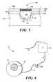
- FIG. 6is a perspective view of one embodiment of a medical device having an implantable sensor portion (or sensor unit) and a separate drug delivery portion (or drug unit).
- FIG. 7is a cross-sectional view of one embodiment of sensor device with the sensor electrodes disposed in a reservoir covered by a disintegratable reservoir cap, where the working electrode and counter electrode extend through vias in the substrate for electrical connection.
- FIG. 8is a cross-sectional view of another embodiment of sensor device with the sensor electrodes disposed in a reservoir covered by a disintegratable reservoir cap, where the working electrode and counter electrode extend through vias in the substrate for electrical connection.
- FIG. 9is a cross-sectional view of still another embodiment of sensor device with the sensor electrodes disposed in a reservoir covered by a disintegratable reservoir cap, where the working electrode and counter electrode extend through vias in the substrate for electrical connection.
- the devices and methodscomprise implantable sensors, such as for use in in vivo sensing, e.g., of glucose, in a human or other animal.
- the devices and methodsoptionally can further comprise drug delivery means in communication with the sensors.
- the devices described hereinincludes a plurality of reservoirs containing reservoir contents (such as a sensor or reactant), where each reservoir is covered by a selectively removable reservoir cap (i.e., a barrier layer) that protects the reservoir contents from one or more components of the surrounding environment until such time as exposure or release is desired.
- a selectively removable reservoir capi.e., a barrier layer
- these environmental componentsinclude chemicals, cells, proteins, water, air or other gases, biological fluids and constituents thereof, as well as certain forms of energy, such as light or heat.
- the improvementsinclude (1) a reservoir contents destruction mechanism to interrupt the release or exposure of reservoir contents, for example, to deactivate an unneeded sensor and prevent it from negatively impacting other (nearby) sensors, (2) a protective covering material layer over the sensor underneath the reservoir cap, which protects the sensor membrane and sensor during reservoir cap disintegration and then is removed, (3) a device design for containing sensors in shallow, wide reservoir structures to enhance sensor exposure by minimizing molecular diffusion distances, (4) a device having an implantable sensor unit and a separate drug delivery unit, and (5) combinations thereof.
- an implantable medical devicefor the controlled exposure of a secondary device, particularly a sensor, such as a glucose sensor.
- the deviceincludes at least one substrate, a plurality of reservoirs in the substrate, an operational secondary device in one or more of the reservoirs, a reservoir cap covering each of the reservoirs to isolate the secondary device from an environmental component outside the reservoirs wherein the reservoir is impermeable to the environmental component, means for disintegrating or permeabilizing the reservoir cap to expose the secondary device to the environmental component; and means for selectively rendering the secondary device inoperable.
- the deviceincludes at least one substrate, a plurality of reservoirs in the substrate, a secondary device in one or more of the reservoirs, a reservoir cap covering each of the reservoirs to isolate the secondary device from an environmental component outside the reservoirs wherein the reservoir is impermeable to the environmental component, a biodegradable intermediary material disposed in the reservoir underneath the reservoir cap and covering the secondary device, and means for disintegrating or permeabilizing the reservoir cap to expose the biodegradable intermediary material to cause the biodegradable intermediary material to disintegrate to expose the secondary device to the environmental component.
- the biodegradable intermediary materialis water miscible, such as a water-soluble solid, liquid, or gel, a hydrophilic polymer matrix (e.g., a hydrogel), or a liquid that readily mixes with an aqueous fluid.
- the liquid mixtureshould permit an analyte (such as glucose) to diffuse through it to reach a sensor thereunder.
- a medical devicein another aspect, includes an implantable sensor portion (or sensor unit) and a separate drug delivery portion (or drug unit).
- the drug delivery portioncan be implantable or designed to be worn externally.
- the sensor portion and the drug delivery portionoperate together to sense in vivo a chemical entity or physiological condition and deliver one or more drugs as therapeutically indicated, based at least in part on a signal from the sensor portion.
- Electrothermal ablationincludes passing electric current through a conductive structure to locally heat it in an amount effective to “rupture” it, e.g., an electrically-induced thermal shock that causes the structure to fracture and/or lose structural integrity due to a phase change, (e.g., melting or vaporization), either or both of which are caused by the generation of heat within the structure as a result of electric current flowing through it.
- a phase changee.g., melting or vaporization
- the heatingis believed to cause the structure to degrade by melting (or vaporizing), thermal shock, and/or a mismatch in the coefficient of thermal expansion, analogous to the process by which a conventional simple electrical fuse heats and then disintegrates (e.g., burns up) upon passage of an excessive amount of electrical current through it.).
- This rupturable structureis sometimes referred to herein as a “fuse.”
- the means for selectively rendering the secondary device inoperablecomprises an electrothermal ablation-based destruction mechanism.
- a fuseis provided beneath a glucose oxidase-based sensor in a reservoir, as shown in FIG. 1 .
- FIG. 1shows a single, opened reservoir, although the device 30 would include a plurality of reservoirs, each of which would be sealed with a reservoir cap prior to actuation of the reservoir.
- Device 30includes a substrate consisting of a lower substrate portion 32 a and an upper substrate portion 32 b in which reservoir 34 is disposed.
- a sensoris provided in the reservoir and includes working electrode 42 , counter electrode 44 , and glucose oxidase 46 .
- the device 30further includes a sensor deactivation mechanism, which includes fuse 36 and fuse traces 38 a and 38 b .
- An insulating dielectric layer 40separates the working and counter electrodes 42 , 44 from the fuse and fuse traces 36 , 38 .
- the fuse 36is blown, thus destroying the sensor. Residual active glucose oxidase may remain.
- the means for selectively rendering the secondary device inoperablecomprises a thermal destruction mechanism based on conventional resistive heating.
- a resistoris provided beneath a glucose oxidase-based sensor in a reservoir, as shown in FIG. 2 , which for simplicity also shows a single, opened reservoir, although the device 50 would include a plurality of reservoirs, each of which would be sealed with a reservoir cap prior to actuation of the reservoir.
- Device 50includes a substrate consisting of a lower substrate portion 32 a and an upper substrate portion 32 b in which reservoir 34 is disposed.
- a sensoris provided in the reservoir and includes working electrode 42 , counter electrode 44 , and glucose oxidase 46 .
- the device 50further includes a sensor deactivation mechanism, which includes resistor 51 and current traces 52 a and 52 b .
- a thin insulating dielectric layer 40separates the working and counter electrodes 42 , 44 from the resistor and current traces 51 , 52 .
- an electric currentis passed through the resistor 51 , heating the glucose oxidase to a temperature effective to deactivate the enzyme. This will eliminate the possibility of residual peroxide formation and resulting sensor crosstalk.
- the “render inoperable” stepwould be used after the sensor or sensor component has been exposed and used to detect or measure.
- a medical devicecomprising device 30 or device 50 , respectively, preferably comprises an array of tens or hundreds of such reservoirs/sensors.
- the enzyme 46optionally and preferably would be covered by a selectively porous membrane as known in the art to control the diffusion of glucose and/or other molecules to the enzyme. See, for example, U.S. Pat. No. 4,759,828, which is incorporated herein by reference.
- the medical devicespreferably include reservoir caps and mechanisms for selectively disintegrating or permeabilizing the reservoir caps to open the reservoir and expose the sensor therein, so that the glucose sensors are protected from the surrounding environment until it is desired to expose them.
- the means for selectively rendering the secondary device inoperableinvolves a chemical reaction mechanism.
- a chemical reactioncould be initiated beneath the sensor, to produce energy, an expanding gas, or a reaction product that chemically deactivates the sensor.
- a single reservoircontains more than one sensor.
- two sensorscould be provided in a side-by-side arrangement, for instance in a relatively larger reservoir. These could work in parallel, e.g., to provide two signals simultaneously, or they could be redundant, e.g., where the second one is used when/if the first one fails.
- a protective covering materialis provided over the sensor in the reservoir, underneath the reservoir cap.
- the protective covering materialprotects the sensor membrane and sensor during reservoir cap disintegration, e.g., by an electrothermal ablation mechanism.
- the protective covering materialis removed by the body or is otherwise displaced to expose the functional sensor for operation.
- the protective coveringdissolves into the body so that the sensor can contact one or more environmental components (e.g., analytes, proteins, antibodies, and the like) or forces (e.g., pressure).
- the protective coveringinclude biocompatible gases and biodegradable solids and liquids.
- the protective coveringis a biodegradable intermediary material.
- biodegradable intermediary materialrefers to a solid, liquid, or gel material that is water miscible or that is dissolved, chemically or physically degraded, and/or adsorbed by the body of a patient in vivo.
- the biodegradable intermediary materialis water miscible, such as a water-soluble solid, liquid, or gel, a hydrophilic polymer matrix (e.g., a hydrogel), or a liquid that readily mixes with an aqueous fluid.
- the liquid mixtureshould permit an analyte (such as glucose) to diffuse through it to reach a sensor thereunder.
- suitable water-soluble materialsinclude biocompatible polymers, such as a polyethylene glycol (PEG) or a polyethylene oxide (PEO).
- the materialis a bioerodible or biodegradable polymer, such as a copolymer of poly(lactic-co-glycolic) acid (PLGA), rather than a water-soluble polymer.
- the biodegradable intermediary materialcan be in a porous form to enhance the dissolution or disintegration kinetics.
- the protective coveringis an evacuated or gas-filled space.
- gasesinclude air, oxygen, nitrogen, helium, or argon.
- a gaseous layer beneath the reservoir caps that open by electrothermal ablationbecause such a configuration could increase the efficiency of the opening mechanism. For instance, if the reservoir cap is in contact with a medium that allows heat to easily pass away (e.g., a solid or liquid having high thermal conductivity), then it would require more electric current to electrothermally ablate the reservoir cap than would be required if the reservoir cap is in contact with a gas or other good thermal insulator.
- airBy using air as the protective layer, less electric current must be passed through the reservoir cap to heat it to the point of failure, i.e., to electrothermally ablate it or “blow the fuse.”
- Device 99(which for example would be part of an implantable medical device) includes substrate 100 having reservoir 103 , which contains a sensor which includes working electrode 106 , counter electrode 108 , enzyme 110 , and sensor membrane 112 .
- the reservoiris covered by reservoir cap 102 , which is connected to electric traces 104 a and 104 b .
- a water-soluble material 114is provided as a protective covering between the reservoir cap and the sensor.
- device 99could further include a sensor-deactivation mechanism (not shown) built underneath the sensor in/on the substrate.
- Device 109(which for example would be part of an implantable medical device) includes substrate 100 having reservoir 103 , which contains a sensor which includes working electrode 106 , counter electrode 108 , enzyme 110 , and sensor membrane 112 .
- the reservoiris covered by reservoir cap 102 , which is connected to electric traces 104 a and 104 b .
- a hollow cavity 118is provided over the sensor membrane, and underneath a thin dielectric or other structural layer 116 .
- device 109could further include a sensor-deactivation mechanism (not shown) built underneath the sensor in/on the substrate. The dielectric and hollow cavity protect the sensor membrane and sensor during reservoir cap disintegration. When the reservoir cap is disintegrated (e.g., by electrothermal ablation), the dielectric/structural layer is also destroyed, exposing the functional sensor for operation.
- the hollow cavity of device 109could be made in a number of different fabrication approaches.
- a soluble materialsuch as a water-soluble polymer
- the thin dielectric material layer or other structural layeris deposited over the soluble material.
- small holes or slatsare etched through the structural layer over the water-soluble material, and then the structure is then soaked in a solvent, e.g., water, to cause the soluble material to dissolve out, leaving in its place a hollow cavity.
- a solvente.g., water
- This hollow cavityoptionally may be filled with a fluid, such as a gas or liquid.
- a fluidsuch as a gas or liquid.
- the holes or slatsare small enough that the reservoir cap can be deposited over them, or a polymeric material can be used to plug the holes or slats prior to deposition of the reservoir cap.
- FIGS. 1-5show the sensor layer being located inside (and near the bottom of) a relatively deep reservoir.
- the reservoirit would be more preferable for (1) the reservoir to be shallow such that there is little to no distance between the surface of the sensor and the outer surface of the substrate, and/or (2) the sensor layer to be positioned on a substrate, such that there is no unfilled or empty space between the reservoir cap and the sensor layer.
- diffusional mass transferof, for example, glucose or other analytes
- the sensor deviceis built up layer by layer, instead of by bonding two substrates together.
- the “reservoir”is the space below the reservoir cap that contains the sensor materials, including the electrodes, enzyme, and polymeric membrane.
- the area denominated as the “reservoir”might actually be spatially located “above” that which typically is referred to as the substrate, in that the bottom of the sensor may be fabricated on the top surface of the substrate.
- the term “reservoir”includes embodiments where the sensor is located in a defined space beneath the reservoir cap, and the term “substrate” includes the bottom substrate and other structural material layers built up thereon and around the sensor. Examples of such embodiments are illustrated in FIGS. 7-9 .
- FIG. 7shows device 200 , which includes substrate 202 and a reservoir defined within a reservoir cap 204 and a structural material 207 .
- the reservoircontains a sensor comprising working electrode 206 , counter electrode 208 , semi permeable sensor membrane 210 , sensor chemical component 212 , and space 214 .
- the chemical componentcould be glucose oxidase mixed with a binder material.
- the spacecould be empty or filled, for example, with a gas or water-soluble material.
- the working electrode 206 and counter electrode 208are electrically connected to other device electronics through vias 206 b , 208 b and electrical traces 206 a , 208 a .
- Device 250includes substrate 202 and a reservoir defined within a reservoir cap 204 and a structural material 207 .
- the reservoircontains a sensor comprising working electrode 206 , counter electrode 208 , semi permeable sensor membrane 210 , sensor chemical component 212 , and space 215 .
- the working electrode 206 and counter electrode 208are electrically connected to other device electronics through vias 206 b , 208 b and electrical traces 206 a , 208 a .
- electric currentis passed through the reservoir cap 204 through input and out leads 205 a and 205 b to electrothermally ablate the reservoir cap, disintegrating it and exposing the sensor therebeneath.
- space 215extends between the reservoir cap 204 and the sensor membrane 210 .
- the spacecould be empty or filled, for example, with a gas or water-soluble material.
- Device 260includes substrate 202 , reservoir cap 204 , and a sensor built into structural material layer 207 .
- the sensorcomprises working electrode 206 , counter electrode 208 , semi permeable sensor membrane 210 , and sensor chemical component 212 .
- the working electrode 206 and counter electrode 208are electrically connected to other device electronics through vias 206 b , 208 b and electrical traces 206 a , 208 a .
- electric currentis passed through the reservoir cap 204 through input and out leads 205 a and 205 b to electrothermally ablate the reservoir cap, disintegrating it and exposing the sensor therebeneath.
- methods of fabricating sensor devicesare provided.
- the devices described hereincan be made by various processes.
- the materials/layersare built up by a series of steps using deposition and etching techniques known in the art.
- Other fabrication and microfabrication methods known in the art that can be used or adapted to make the devicesinclude lithography and etching, injection molding and hot embossing, electroforming/electroplating, microdrilling (e.g., mechanical drilling, laser drilling, ultrasonic drilling), micromilling, electrical discharge machining (EDM), photopolymerization, surface micromachining, high-aspect ratio methods (e.g., LIGA), micro stereo lithography, silicon micromachining, rapid prototyping, DEEMO (Dry Etching, Electroplating, Molding), and build-up or lamination techniques, such as LTCC (low temperature co-fired ceramics). See, for example, U.S. Pat. Nos. 6,123,861 and 6,808,522.
- a sensor substrate subpart 62is fabricated, a reservoir/opening substrate subpart 60 is fabricated, and then the two subparts are bonded together to form a complete device 70 with sensors sealed inside reservoirs.
- the reservoir/opening substrate subpart 60includes substrate portion 64 , reservoirs 63 , and reservoir caps 68 (with actuation circuitry not shown).
- the sensor substrate subpart 62includes glucose sensors 69 (e.g., working and counter electrodes and glucose oxidase) and sensor deactivator fuses 51 on substrate portion 66 .
- the bonding steprequires avoidance of high temperatures that would prematurely damage the glucose oxidase. Bonding and hermetic sealing techniques which could be useful in fabricating the devices are described in U.S.
- a medical devicein another aspect, includes an implantable sensor portion (or sensor unit) and a separate drug delivery portion (or drug unit).
- the drug delivery portioncan be implantable or designed to be worn externally.
- the sensor portion and the drug delivery portionoperate together to sense in vivo a chemical entity or physiological condition and deliver one or more drugs as therapeutically indicated, based at least in part on a signal from the sensor portion.
- the sensor unitcomprises a multi-reservoir device with reservoir-based sensors as described above and illustrated in FIGS. 1-5 and 7 - 9 .
- the deviceincludes features for communication between the drug delivery portion and the sensor portion.
- the communicationis through tissue and/or air by transmission of digital/analog light, electromagnetic (e.g., RF), sonic/acoustic energy, hydraulic energy, or combinations thereof, with or without conductors.
- conductorsinclude wire, optical fiber, and fluid-filled lumens for sonic or hydraulic energy conduction.
- the communication featureincludes one or more of signal encoders/transducers, emitters, receivers, and decoders/transducers.
- the wirepreferably is provided with mating hardware, such as a plug or other selectively disconnectable connector, which permits the two portions to be separated and connected as needed.
- mating hardwaresuch as a plug or other selectively disconnectable connector
- FIG. 6An example of a two-portion device is illustrated in FIG. 6 . It shows a device 10 which comprises a sensor unit 12 and a drug delivery unit 14 , which are connected by wires 16 and 18 , where wires 16 and 18 can be joined together by a female connector 20 a and a male connector 20 b .
- Drug delivery unit 14is a pump which discharges drug through flexible catheter 22 .
- Sensor unit 12comprises an array of reservoirs 24 , each of which contains a sensor.
- the sensor unitcomprises a controller, which can relay instructions to the drug delivery unit 14 via wires 16 and 18 .
- the drug unitcomprises a fully implantable infusion pump (IIP), which is intended to provide long-term continuous or intermittent drug infusion.
- IIPfully implantable infusion pump
- the route of administrationcan include intravenous, intra-arterial, subcutaneous, intraperitoneal, intrathecal, epidural, and intraventricular.
- the IIPis surgically placed in a subcutaneous pocket under the intraclavicular fossa or in the abdominal wall, and a catheter extending from the IIP is threaded into the therapeutically desirable location.
- the drug unitis an externally worn infusion pump and provided with a catheter through the patient's skin.
- the pumpscan operate by a number of driving mechanisms including peristalsis, fluorocarbon propellant, osmotic pressure, piezoelectric disk benders, or the combination of osmotic pressure with an oscillating piston.
- driving mechanismsinclude those described in U.S. Pat. No. 6,805,693 to Gray et al., U.S. Pat. No. 6,554,800 to Nezhadian et al., and U.S. Pat. No. 6,375,638 to Nason et al.
- the drug delivery portioncomprises a multi-reservoir device with an active release mechanism.
- the drug delivery portioncomprises one or more microchip devices comprising an array of microreservoirs containing one or more drugs for release.
- the drug delivery portioncomprises a microtube device or other device for accelerated release described in U.S. patent application Publication No. 2004/0106914 A1 to Coppeta, et al.
- the drug delivery portionhas a cylindrical or spherical body having one or more regions or surface areas over which multiple reservoirs, such as microreservoirs, are disposed.
- an apparatusfor use in the management of diabetes.
- the apparatusincludes an insulin supply and delivery unit, a glucose-monitoring (sensing) unit, and a controller that communicates with both units.
- the insulin supply and delivery unit(which can be externally worn or fully implantable) comprises (1) a refillable reservoir containing insulin, and (2) a pump for delivering the insulin to patient.
- the glucose-monitoring unitcomprises an array of discrete reservoirs each comprising individual glucose sensors covered by a selectively removable reservoir cap.
- the controllerwhich typically comprises a microprocessor, can be part of either the insulin delivery unit or the glucose-monitoring unit, or it can be a separate unit adapted to operably communicate with both the glucose sensors and the insulin delivery.
- the controllercan monitor a patient's glucose level and can direct the insulin unit to deliver more or less insulin depending upon the monitored glucose level. The controller would make dosing decisions based on an acceptable algorithm. The controller also can monitor the accuracy and stability of each glucose sensor. When it senses that the active sensor is not reading properly (e.g., because it has become fouled), then the controller can direct the monitoring unit to open another reservoir to expose a new sensor. The controller optionally can direct the destruction of the old sensor to avoid potential interference with operation of the new one.
- a medical devicefor use in the treatment of cancer or hormone therapy, where long-term drug delivery is needed and an in vivo sensor can be used to monitor physiological chemical or condition useful in determining the appropriate dosage of therapeutic agent to deliver.
- the sensing deviceincludes a substrate having a plurality of reservoirs, which contain sensors, and optionally drug molecules for release.
- the substrate, reservoirs, reservoir caps, control circuitry, and power sourceare described herein and in U.S. Pat. Nos. 5,797,898, 6,123,861, 6,551,838, 6,491,666, and 6,527,762, as well as U.S. Patent Application Publications No. 2002/0138067, No. 2002/0072784, No. 2002/0151776, and No. 2002/0107470.
- control of reservoir cap openingincludes electro-thermal ablation techniques, as described in U.S. Patent Application Publication No. 2004/0121486 to Uhland, et al., which is incorporated herein by reference.
- the devicemay be a microchip device, or the reservoirs/sensors/reservoir caps can be integrated into another type of device.
- reservoir deviceis used to refer to the device comprising a substrate and reservoirs, as distinguished from the “secondary device,” which is disposed in the reservoirs of the reservoir device.
- the substrateis the structural body (e.g., part of a device) in which, or on which, the reservoirs are formed.
- a reservoircan be a well, a container, or other space in which reservoir contents are stored, as described above.
- MEMS methods, micromolding, and micromachining techniques known in the artcan be used to fabricate the substrate/reservoirs from a variety of materials. See, for example, U.S. Pat. No. 6,123,861 and U.S. Patent Application Publication No. 2002/0107470.
- suitable substrate materialsinclude metals, ceramics, semiconductors, and degradable and non-degradable polymers. Biocompatibility of the substrate material typically is preferred for in vivo device applications.
- the substrate, or portions thereof,may be coated, encapsulated, or otherwise contained in a biocompatible material (e.g., poly(ethylene glycol), polytetrafluoroethylene-like materials, inert ceramics, diamond-like materials, titanium, and the like) before use.
- a biocompatible materiale.g., poly(ethylene glycol), polytetrafluoroethylene-like materials, inert ceramics, diamond-like materials, titanium, and the like
- the substrateis formed of silicon.
- the substrateis hermetic, that is impermeable (at least during the time of use of the reservoir device) to the molecules to be delivered and to surrounding gases or fluids (e.g., water, blood, electrolytes or other solutions).
- the substrateis made of a strong material that degrades or dissolves over a defined period of time into biocompatible components.
- biocompatible polymersinclude poly(lactic acid)s, poly(glycolic acid)s, and poly(lactic-co-glycolic acid)s, as well as degradable poly(anhydride-co-imides).
- the substratemay consist of only one material, or may be a composite or multi-laminate material, that is, composed of several layers of the same or different substrate materials that are bonded together.
- the substratecan be flexible or rigid, and it can be in various shapes and have a range of differently shaped surfaces.
- the substratemay, for example, be in a shape selected from disks, cylinders, or spheres.
- itcan have a first side for release/exposure of reservoir contents and a second, opposite side, wherein the release side is shaped to conform to a curved tissue surface or into a body lumen and the back side (distal the release side) is shaped to conform to an attachment surface.
- the substrate thicknesscan vary depending upon the particular device and application using the activation system described herein.
- the thickness of a devicemay vary from approximately 10 ⁇ m to several millimeters (e.g., 500 ⁇ m).
- Total substrate thickness and reservoir volumecan be increased by bonding or attaching wafers or layers of substrate materials together.
- the device thicknessmay affect the volume of each reservoir and/or may affect the maximum number of reservoirs that can be incorporated onto a substrate.
- the size and number of substrates and reservoirscan be selected to accommodate the quantity and volume of reservoir contents needed for a particular application, although other constraints such as manufacturing limitations or total device size limitations (e.g., for implantation into a patient) also may be important design factors.
- devices for in vivo applicationsdesirably would be small enough to be implanted using minimally invasive procedures, such as via a trochar or injection technique.
- the substrateincludes at least two and preferably tens or hundreds of reservoirs.
- the substratecould include, for example, 200 to 400 reservoirs, each containing a sensor.
- reservoirsfor simplicity, only one or two reservoirs are shown in the Figures herein; however, it is understood that a device, particularly an implantable medical device preferably would contain an array of many more reservoirs.
- the reservoirhas a volume equal to or less than 500 ⁇ L (e.g., less than 250 ⁇ L, less than 100 ⁇ L, less than 50 ⁇ L, less than 25 ⁇ L, less than 100 ⁇ L, etc.) and greater than about 1 nL (e.g., greater than 5 nL, greater than 10 nL, greater than about 25 nL, greater than about 50 nL, greater than about 1 ⁇ L, etc.).
- the volume of the reservoiris larger than 500 ⁇ L.
- a single reservoirmay preferably include two or more reservoir caps, as described in U.S. Patent Application No. 60/606,387, which is incorporated herein by reference.
- the devicescontain sensors, sensor components, or other devices or device components that need to be protected from surrounding environmental components until their exposure is desired. These sensors, sensor components, or other devices or device components are sometimes referred to herein as “secondary devices.”
- the reservoirsmay alternatively or additionally include other reservoir contents such as reacting components.
- the secondary deviceis a sensor or sensing component.
- a “sensing component”includes a component utilized in measuring or analyzing the presence, absence, or change in a chemical or ionic species, energy, or one or more physical properties (e.g., pH, pressure) at a site.
- Types of sensorsinclude biosensors, chemical sensors, physical sensors, or optical sensors.
- Preferred sensorsmeasure properties such as biological activity, chemical activity, pH, temperature, pressure, optical properties, radioactivity, and electrical conductivity.
- Other possible properties to measureinclude glucose and blood gases, such as oxygen and carbon dioxide. These may be discrete sensors (e.g., “off-the-shelf” sensors) or sensors integrated into or onto the substrate.
- Biosensorstypically include a recognition element such as an enzyme or antibody or nucleic acid.
- the transducer used to convert the interaction between the analyte and recognition element into an electronic signalmay be, for example, electrochemical, optical, piezoelectric, or thermal in nature.
- Representative examples of biosensors constructed using microfabrication methodsare described in U.S. Pat. Nos. 5,200,051; 5,466,575; 5,837,446; and 5,466,575 to Cozzette, et al.
- the senorcomprises a differential oxygen sensor or other sensor known in the art that has two (or more) working electrodes.
- glucose oxidase or other enzymecan be immobilized on one working electrode and not on a second working electrode and the differential between the detection levels is used to determine concentration of an analyte. See, for example, U.S. Pat. No. 6,498,043, which is expressly incorporated herein by reference.
- each reservoircan contain a different chemical or molecule for release.
- the chemical contained in the reservoiris an enzyme, glucose oxidase, which is used in some glucose sensing devices.
- the device reservoirscontain another type glucose sensor.
- a single devicemay be comprised of three components, each of which is located in a different reservoir.
- a medical devicehas the ability to selectively expose each chemical, device, or device component to the environment outside of the reservoir and to vary the number and type of chemicals and devices associated with each reservoir.
- the output signal from the devicecan be recorded and stored in writeable computer memory chips.
- the output signal from the devicecan be directed to a microprocessor for analysis and processing.
- the signalcan be sent to a remote location away from the reservoir device.
- the reservoir devicecan be provided with a transmitter (RF, ultrasound, magnetic, etc.) in order to transmit a signal (e.g., data) from the reservoir device to a computer or other remote receiver.
- the reservoir devicecan also be controlled using the same or similar transmission mechanisms. Power can be supplied to the reservoir device locally by a battery or remotely by wireless transmission.
- reacting componentincludes any chemical species which can be involved in a reaction, including reagents; catalysts, including enzymes, metals, and zeolites; proteins; nucleic acids; polysaccharides; polymers; cells, as well as organic or inorganic molecules, including diagnostic agents.
- the reacting component contained within a reservoirmay be present in any form (e.g., solid, liquid, gel, or vapor). It may be present in the reservoir in pure form or as a mixture with other materials.
- the chemicalsmay be in the form of solid mixtures, such as amorphous and crystalline mixed powders, porous or nonporous monolithic solid mixtures, and solid interpenetrating networks; liquid mixtures or solutions, including emulsions, colloidal suspensions, and slurries; and gel mixtures, such as hydrogels.
- solid mixturessuch as amorphous and crystalline mixed powders, porous or nonporous monolithic solid mixtures, and solid interpenetrating networks
- liquid mixtures or solutionsincluding emulsions, colloidal suspensions, and slurries
- gel mixturessuch as hydrogels.
- the chemicalsare zeolites used for a heterogeneous reaction.
- the reagentsdiffuse into the reservoir to react at the surface or in the interior of the zeolite catalyst, which remains in the reservoir.
- the material in the reservoircan include one or more lyophilized components. Such lyophilized materials can be loaded into the reservoir following lyophilization or alternatively a fluid component containing the material can be loaded into the reservoirs and then subsequently lyophilized.
- the deviceincludes one or more biosensors (which may be sealed in reservoirs until needed for use) that are capable of detecting and/or measuring signals within the body of a patient.
- biosensorincludes sensing devices that transduce the chemical potential of an analyte of interest into an electrical signal (e.g., an ion selective field effect transistor or ISFET), as well as electrodes that measure electrical signals directly or indirectly (e.g., by converting a mechanical or thermal energy into an electrical signal).
- the biosensormay measure intrinsic electrical signals (EKG, EEG, or other neural signals), pressure, temperature, pH, or mechanical loads on tissue structures at various in vivo locations.
- the electrical signal from the biosensorcan then be measured, for example by a microprocessor/controller, which then can transmit the information to a remote controller, another local controller, or both.
- a microprocessor/controllerwhich then can transmit the information to a remote controller, another local controller, or both.
- the systemcan be used to relay or record information on the patient's vital signs or the implant environment, such as drug concentration.
- the reservoir contentsfurther include a confining layer incorporated between the sensor or a reagent and the space above.
- the confining layerpermits transport of an analyte to reach the reagent or sensor, prevents one or more non-analyte substances from contacting the reagent or sensor, and secures or contains the sensor/reagent to prevent dissipation into the body, which may degrade the sensor/reagent or may be deleterious to the patient's body.
- the confining layeris a polymer, a microporous structure, or a hydrogel.
- the term “reservoir cap”includes a membrane or other structure suitable for separating the contents of a reservoir from the environment outside of the reservoir. It generally is self-supporting across the reservoir opening. The devices, however, can further include additional structures fabricated to provide mechanical support to the reservoir cap. In another embodiment, the reservoir cap is supported by or resting directly or indirectly on the material to be covered/protected, such as the drug formulation or biosensor.
- multiple reservoir capsmay be located over an individual reservoir and supported by a grid structure, as described in U.S. Patent Application No. 60/606,387, which is incorporated herein by reference.
- Such multiple capsallow a larger area of the reservoir to be exposed than may be feasible using a single large cap. For example, opening a large cap may require more power or generation of more heat that could damage tissue or sensors compared to opening several smaller caps. Smaller caps may be opened simultaneously or sequentially.
- the reservoir capis selectively disintegrated.
- the term “disintegrate”is used broadly to include without limitation degrading, dissolving, rupturing, fracturing or some other form of mechanical failure, as well as a loss of structural integrity due to a chemical reaction (e.g., electrochemical degradation) or phase change (e.g., melting) in response to a change in temperature, unless a specific one of these mechanisms is indicated.
- the “disintegration”is by an electrochemical activation technique, such as described in U.S. Pat. No.
- the “disintegrate” or “rupture” of the reservoir capis conducted by a mechanism described in U.S. Pat. Nos. 6,527,762 or 6,491,666.
- the “disintegration”is by an electro-thermal ablation technique, as described in U.S. patent application Publication No. 2004/0121486 to Uhland, et al. These patents and applications are expressly incorporated herein by reference.
- the reservoir capgenerally includes any material that can be disintegrated or permeabilized in response to an applied stimulus, e.g., electric field or current, magnetic field, change in pH, or by thermal, chemical, electrochemical, or mechanical means.
- an applied stimuluse.g., electric field or current, magnetic field, change in pH, or by thermal, chemical, electrochemical, or mechanical means.
- the reservoir capis a thin metal film and is impermeable to the surrounding environment (e.g., body fluids or another chloride containing solution).
- a particular electric potentialis applied to the metal reservoir cap, which is then oxidized and disintegrated by an electrochemical reaction, to expose the sensor located in the reservoir.
- suitable reservoir cap materialsinclude gold, silver, copper, and zinc.
- the reservoir capis heated (e.g., using resistive heating) to cause the reservoir cap to melt and be displaced from the reservoir to open it.
- This latter variationcould be used, for example, with reservoir caps formed of a metal or a non-metal material, e.g., a polymer.
- the reservoir capis formed of a polymer or other material that undergoes a temperature-dependent change in permeability such that upon heating to a pre-selected temperature, the reservoir cap is rendered permeable to molecules involved in the sensing function.
- the reservoir capis formed of a conductive material, such as a metal film, through which an electrical current can be passed to electrothermally ablate it, as described in U.S. patent application Publication No. 2004/0121486 to Uhland, et al.
- suitable reservoir cap materialsinclude gold, copper, aluminum, silver, platinum, titanium, palladium, various alloys (e.g., Au/Si, Au/Ge, Pt—Ir, Ni—Ti, Pt—Si, SS 304, SS 316), and silicon doped with an impurity to increase electrical conductivity, as known in the art.
- the reservoir capis in the form of a multi-layer structure, such as a multi-layer/laminate structure of platinum/titanium/platinum.
- the reservoir capis operably (i.e., electrically) connected to an electrical input lead and to an electrical output lead, to facilitate flow of an electrical current through the reservoir cap.
- an effective amount of an electrical currentis applied through the leads and reservoir cap, the temperature of the reservoir cap is locally increased due to resistive heating, and the heat generated within the reservoir cap increases the temperature sufficiently to cause the reservoir cap to be electrothermally ablated (ruptured or disintegrated).
- the reservoir capis formed from a material or mixture of materials that degrade, dissolve, or disintegrate over time, or that do not degrade, dissolve, or disintegrate, but are permeable or become permeable to molecules or energy.
- Representative examples of reservoir cap materialsinclude polymeric materials, and non-polymeric materials such as porous forms of metals, semiconductors, and ceramics.
- Passive semiconductor reservoir cap materialsinclude nanoporous or microporous silicon membranes.
- the devicepreferably is provided with a control means to control the time at which the reservoir is opened and/or the sensor exposed.
- control meansto control the time at which the reservoir is opened and/or the sensor exposed.
- control meanscan include the hardware, electrical components, and software needed to control and deliver the electric current from a power source to selected reservoir caps for actuation (i.e., opening).
- the control meanscan include an input source, a microprocessor, a timer, a demultiplexer (or multiplexer), and a power source.
- demultiplexeralso refers to multiplexers.
- the power sourceprovides energy to activate the selected reservoir.
- the operation of the reservoir opening systemcan be controlled by an on-board microprocessor (e.g., the microprocessor is within an implantable or insertable device).
- the microprocessorcan be programmed to initiate the disintegration or permeabilization of the reservoir cap at a pre-selected time or in response to one or more of signals or measured parameters, including receipt of a signal from another device (for example by remote control or wireless methods) or detection of a particular condition using a sensor such as a biosensor.
- a simple state machineis used, as it typically is simpler, smaller, and/or uses less power than a microprocessor.
- the devicecan also be activated or powered using wireless means, for example, as described in U.S. 20020072784 A1 to Sheppard et al.
- the activation meanscomprises one or more capacitors.
- capacitorscould be used in the thermal ablation reservoir opening circuitry.
- the activation meanscomprises power and data transmission means that include the use of modulated ultrasonic energy. See, e.g., U.S. Pat. No. 6,432,050 to Porat et al.
- the deviceincludes a substrate having a two-dimensional array of reservoirs arranged therein, anode reservoir caps covering each of the reservoirs, cathodes positioned on the substrate near the anodes, and means for actively controlling disintegration of the reservoir caps.
- the meansincludes a power source and circuitry to control and deliver an electrical potential energy. That is, the control circuitry can have potentiostat/galvanostat functionality to drive a reaction between selected anodes and cathodes.
- the microprocessordirects power to specific electrode pairs through a demultiplexer as directed by an EPROM, remote control, or biosensor.
- the control meanscontrols electro-thermal ablation of the reservoir cap.
- the devicecould include a reservoir cap formed of an electrically conductive material; an electrical input lead connected to the reservoir cap; an electrical output lead connected to the reservoir cap; and a control means to deliver an effective amount of electrical current through the reservoir cap, via the input lead and output lead, to locally heat and rupture the reservoir cap to expose the sensor.
- the reservoir cap and conductive leadsare formed of the same material, where the temperature of the reservoir cap increases locally under applied current because the reservoir cap is suspended in a medium that is less thermally conductive than the substrate.
- the reservoir cap and conductive leadsare formed of the same material, and the reservoir cap has a smaller cross-sectional area in the direction of electric current flow, where the increase in current density through the reservoir cap causes an increase in localized heating.
- the reservoir capalternatively can be formed of a material that is different from the material forming the leads, wherein the material forming the reservoir cap has a different electrical resistivity, thermal diffusivity, thermal conductivity, and/or a lower melting temperature than the material forming the leads. Various combinations of these embodiments can be employed.
- the reservoirsare arrayed in the substrate in a square matrix (e.g., four or more reservoirs positioned in a two-dimensional array), with the input side of the reservoir caps electrically connected in parallel by row, and the output side of the reservoir caps electrically connected in parallel by column.
- the conductor materialalso can form input leads, output leads, and reservoir caps.
- the reservoir capsare formed of a different material than the leads (or rows or columns of conductor material).
- An insulating materialis provided at the intersection of the columns and rows to prevent short-circuiting. The insulating material can be provided between the upper surface of the column and the lower surface of the row.
- This embodimentprovides a matrix-addressed array with significantly reduced input/output (I/O) requirements.
- the electrically conductive reservoir capsform electrical connections between the rows and columns of the array. When applying a voltage/current to a designated row and column to activate the reservoir cap at the intersection of the row and column, the connections cause current to flow through other reservoir caps.
- additional rows and columnscan be added to the array, and conducting elements added at each of the intersections, to prevent an operable reservoir cap from being exposed to relatively large unintended currents, which might cause premature rupture. These additional conductors could be made of the same material as the reservoir caps, but would not be located over reservoirs.
- the reservoir capsare designed to rupture without creating an open circuit (to retain essentially the same electrical resistance) between the input and output leads.
- a rectifying elementsuch as a diode
- the diodecould be a semiconductor junction diode or a Schottky barrier diode. If a silicon substrate is used in the controlled release device, then the substrate and rectifying element could be integrally formed.
- a reservoir capcan be integrated into the reservoir device fabrication process.
- specific activation of a reservoir capcan be accomplished by integrating a transistor with each reservoir cap.
- such a matrix approachis accomplished with transistors.
- transistorsare integrated onto a microchip substrate, other active electronic components such as multiplexing switches optionally may also be able to be integrated into the reservoir device.
- Microelectronic device packagesare typically made of an insulating or dielectric material such as aluminum oxide or silicon nitride. Low cost packages can also be made of plastics or reinforced epoxies (similar to those used in making printed circuit boards). Their purpose is to allow all components of the device to be placed in close proximity and to facilitate the interconnection of components to power sources and to each other, while protecting the electronics from the environment. Implantable reservoir device packages typically are hermetically sealed, e.g., in a titanium encasement, which essentially exposes only the reservoir caps.
- the control meanscan include a microprocessor, a timer, a demultiplexer, and an input source (for example, a memory source, a signal receiver, or a biosensor), and a power source.
- the timer and demultiplexer circuitrycan be designed and incorporated directly onto the surface of the microchip during electrode fabrication, or may be incorporated in a separate microchip.
- the criteria for selection of a microprocessorare small size, low power requirement, and the ability to translate the output from memory sources, signal receivers, or biosensors into an address for the direction of power through the demultiplexer to a specific reservoir on the microchip device.
- a source of input to the microprocessorsuch as memory sources, signal receivers, or biosensors depends on the microchip device's particular application and whether device operation is preprogrammed, controlled by remote means, or controlled by feedback from its environment (i.e., biofeedback).
- a microprocessoris used in conjunction with a source of memory such as erasable programmable read only memory (EPROM), a timer, a demultiplexer, and a power source such as a battery or a biofuel cell.
- a source of memorysuch as erasable programmable read only memory (EPROM), a timer, a demultiplexer, and a power source such as a battery or a biofuel cell.
- EPROMerasable programmable read only memory
- timererasable programmable read only memory
- demultiplexererasable programmable read only memory
- a power sourcesuch as a battery or a biofuel cell.
- a programmed sequence of eventsincluding the time a reservoir is to be opened and the location or address of the reservoir is stored into the EPROM by the user.
- the microprocessorsends a signal corresponding to the address (location) of a particular reservoir to the demultiplexer.
- the demultiplexerroutes an input, such as an
- the deviceshave numerous in vitro and in vivo applications.
- the devicescan be used in a variety of applications in which it is desired to selectively expose sensors or other secondary devices, or release discrete quantities of drug or other chemical molecules.
- Applicationsinclude controlled or selective, on-demand sensing, for example to detect the presence or absence of a type of molecule, to test for biological activity or reactivity of molecules exposed to the sensor, or to measure parameters, such as pH, temperature, reactivity with another molecule, optical properties (e.g., refractive index, color, or fluorescence), radioactivity, pressure, or electrical conductivity.
- the senoremploys an optical fiber that can be used to sense changes in optical properties in or near the reservoirs, changes which might occur, for example, due to a reaction in the reservoir or in the environment adjacent the reservoir.
- the reservoircontains a scintillation fluid to aid in the (optical) detection of radioactive materials.
- the present devicesare particularly useful in applications where prolonged exposure of a catalyst to the environment results in decreased performance of the catalyst due to “fouling” or coating of the catalyst surface or due to chemical degradation of the catalyst.
- the deviceswould enable many discrete quantities of catalyst to be contained in one small device, with each quantity available independently when needed. For example, if the catalyst of a first reservoir becomes fouled, then a second reservoir can be opened to expose fresh catalyst, and repeated for any number of reservoirs.
- different catalystscan be provided in different reservoirs of a single device, thereby enhancing the range of reactions that can be catalyzed with a single device.
- the devicecontains sensors for use in glucose monitoring and insulin control. Information from the sensor could be used to actively control insulin release from the same device or from a separate insulin delivery device (e.g., a conventional insulin pump, either implanted or externally-worn).
- a separate insulin delivery devicee.g., a conventional insulin pump, either implanted or externally-worn.
- an implantable medical devicehas reservoirs in which pairs of sensors are stored for selective exposure: a reference sensor and a working sensor.
- the reference sensoris used to check the operation of the working sensor.
- a microprocessorpowered by a power source, can be programmed to continuously compare, e.g., using voltmeters or other instrumentation, the operation of the working sensor to the reference sensor in a reservoir. If a first sensor in a first reservoir is not operating properly, a signal can be sent back to the microprocessor, which, in turn, can activate a second reservoir to expose a new pair of electrodes.
- the microprocessorcan send a signal to a transmitter to notify a remotely located computer that one less operational sensor remains or to signal other operational information.
- a present state of the patientis measured by the device and compared to a reference state by statistical and medically relevant criteria. Subsequent programs of sensing and/or drug delivery by the sensing device and/or by a separate drug delivery device are dependent upon the outcome of the comparison.
- the present devicesalso can be used in vitro to selectively expose secondary devices or device components, reacting components, or both to the surrounding environment or components thereof, particularly in the fields of analytical chemistry and medical diagnostics.
- the devicescan release small, controlled amounts of chemical reagents or other molecules into solutions or reaction mixtures at precisely controlled times and rates.
- secondary devicessuch as sensors can be protected from the surrounding environment until they are needed.
- the catalysti.e., enzyme
- the catalysti.e., enzyme
Landscapes
- Health & Medical Sciences (AREA)
- Life Sciences & Earth Sciences (AREA)
- Physics & Mathematics (AREA)
- Engineering & Computer Science (AREA)
- Surgery (AREA)
- Animal Behavior & Ethology (AREA)
- Veterinary Medicine (AREA)
- Biophysics (AREA)
- Pathology (AREA)
- Public Health (AREA)
- Biomedical Technology (AREA)
- Heart & Thoracic Surgery (AREA)
- Medical Informatics (AREA)
- Molecular Biology (AREA)
- Chemical & Material Sciences (AREA)
- General Health & Medical Sciences (AREA)
- Optics & Photonics (AREA)
- Chemical Kinetics & Catalysis (AREA)
- General Chemical & Material Sciences (AREA)
- Bioinformatics & Cheminformatics (AREA)
- Medicinal Chemistry (AREA)
- Pharmacology & Pharmacy (AREA)
- Measurement Of The Respiration, Hearing Ability, Form, And Blood Characteristics Of Living Organisms (AREA)
- Apparatus Associated With Microorganisms And Enzymes (AREA)
- Infusion, Injection, And Reservoir Apparatuses (AREA)
- Medicinal Preparation (AREA)
- Medicines That Contain Protein Lipid Enzymes And Other Medicines (AREA)
- Investigating Or Analysing Biological Materials (AREA)
Abstract
Description
Claims (28)
Priority Applications (1)
| Application Number | Priority Date | Filing Date | Title |
|---|---|---|---|
| US10/980,551US8095197B2 (en) | 2003-11-03 | 2004-11-03 | Medical device for sensing glucose |
Applications Claiming Priority (3)
| Application Number | Priority Date | Filing Date | Title |
|---|---|---|---|
| US51686503P | 2003-11-03 | 2003-11-03 | |
| US57772004P | 2004-06-07 | 2004-06-07 | |
| US10/980,551US8095197B2 (en) | 2003-11-03 | 2004-11-03 | Medical device for sensing glucose |
Publications (2)
| Publication Number | Publication Date |
|---|---|
| US20050096587A1 US20050096587A1 (en) | 2005-05-05 |
| US8095197B2true US8095197B2 (en) | 2012-01-10 |
Family
ID=34556221
Family Applications (1)
| Application Number | Title | Priority Date | Filing Date |
|---|---|---|---|
| US10/980,551Active2030-06-08US8095197B2 (en) | 2003-11-03 | 2004-11-03 | Medical device for sensing glucose |
Country Status (8)
| Country | Link |
|---|---|
| US (1) | US8095197B2 (en) |
| EP (1) | EP1694200B1 (en) |
| JP (1) | JP2007512859A (en) |
| AT (1) | ATE482650T1 (en) |
| AU (1) | AU2004285603A1 (en) |
| CA (1) | CA2543751A1 (en) |
| DE (1) | DE602004029396D1 (en) |
| WO (1) | WO2005041767A2 (en) |
Cited By (21)
| Publication number | Priority date | Publication date | Assignee | Title |
|---|---|---|---|---|
| US20100276005A1 (en)* | 2009-04-30 | 2010-11-04 | Comm. a I'energie atom. et aux energies alterna. | Single use microfluidic valve |
| US9180242B2 (en) | 2012-05-17 | 2015-11-10 | Tandem Diabetes Care, Inc. | Methods and devices for multiple fluid transfer |
| US9322103B2 (en) | 2010-08-06 | 2016-04-26 | Microchips Biotech, Inc. | Biosensor membrane composition, biosensor, and methods for making same |
| US20160135749A1 (en)* | 2013-06-12 | 2016-05-19 | Agency For Science, Technology And Research | Integrated multimodal sensor device for intracranial neuromonitoring |
| US9616171B2 (en) | 2013-08-05 | 2017-04-11 | Cam Med Llc | Conformable patch pump |
| US9700668B2 (en) | 2013-02-28 | 2017-07-11 | Microchips Biotech, Inc. | Implantable medical device for minimally-invasive insertion |
| US9798886B2 (en) | 2015-07-08 | 2017-10-24 | International Business Machines Corporation | Bio-medical sensing platform |
| US9919103B2 (en) | 2012-12-21 | 2018-03-20 | Microchips Biotech, Inc. | Implantable medical device for minimally-invasive insertion |
| US10019555B2 (en) | 2013-10-19 | 2018-07-10 | Cohero Health, Inc. | Interactive respiratory device usage tracking system |
| US10427153B2 (en) | 2011-08-25 | 2019-10-01 | Microchips Biotech, Inc. | Systems and methods for sealing a plurality of reservoirs of a microchip element with a sealing grid |
| US10441765B2 (en) | 2011-08-25 | 2019-10-15 | Microchips Biotech, Inc. | Space-efficient containment devices and method of making same |
| US10799159B2 (en) | 2004-07-13 | 2020-10-13 | Dexcom, Inc. | Analyte sensor |
| US10813577B2 (en) | 2005-06-21 | 2020-10-27 | Dexcom, Inc. | Analyte sensor |
| US10856787B2 (en) | 2005-03-10 | 2020-12-08 | Dexcom, Inc. | System and methods for processing analyte sensor data for sensor calibration |
| US10881788B2 (en) | 2015-10-30 | 2021-01-05 | International Business Machines Corporation | Delivery device including reactive material for programmable discrete delivery of a substance |
| US10888655B2 (en) | 2019-02-19 | 2021-01-12 | Tandem Diabetes Care, Inc. | System and method of pairing an infusion pump with a remote control device |
| US11000474B2 (en) | 2014-09-11 | 2021-05-11 | International Business Machines Corporation | Microchip substance delivery devices |
| US11305057B2 (en) | 2019-03-26 | 2022-04-19 | Tandem Diabetes Care, Inc. | Method and system of operating an infusion pump with a remote control device |
| US11324898B2 (en) | 2013-06-21 | 2022-05-10 | Tandem Diabetes Care, Inc. | System and method for infusion set dislodgement detection |
| US11424017B2 (en) | 2013-10-19 | 2022-08-23 | Aptargroup, Inc. | Respiratory system and method that monitors medication flow |
| US11464908B2 (en) | 2019-02-18 | 2022-10-11 | Tandem Diabetes Care, Inc. | Methods and apparatus for monitoring infusion sites for ambulatory infusion pumps |
Families Citing this family (180)
| Publication number | Priority date | Publication date | Assignee | Title |
|---|---|---|---|---|
| US6036924A (en) | 1997-12-04 | 2000-03-14 | Hewlett-Packard Company | Cassette of lancet cartridges for sampling blood |
| US6391005B1 (en) | 1998-03-30 | 2002-05-21 | Agilent Technologies, Inc. | Apparatus and method for penetration with shaft having a sensor for sensing penetration depth |
| US8641644B2 (en) | 2000-11-21 | 2014-02-04 | Sanofi-Aventis Deutschland Gmbh | Blood testing apparatus having a rotatable cartridge with multiple lancing elements and testing means |
| DE10057832C1 (en) | 2000-11-21 | 2002-02-21 | Hartmann Paul Ag | Blood analysis device has syringe mounted in casing, annular mounting carrying needles mounted behind test strip and being swiveled so that needle can be pushed through strip and aperture in casing to take blood sample |
| AU2002344825A1 (en) | 2001-06-12 | 2002-12-23 | Pelikan Technologies, Inc. | Method and apparatus for improving success rate of blood yield from a fingerstick |
| JP4209767B2 (en) | 2001-06-12 | 2009-01-14 | ペリカン テクノロジーズ インコーポレイテッド | Self-optimized cutting instrument with adaptive means for temporary changes in skin properties |
| US7749174B2 (en) | 2001-06-12 | 2010-07-06 | Pelikan Technologies, Inc. | Method and apparatus for lancet launching device intergrated onto a blood-sampling cartridge |
| US9427532B2 (en) | 2001-06-12 | 2016-08-30 | Sanofi-Aventis Deutschland Gmbh | Tissue penetration device |
| US7344507B2 (en) | 2002-04-19 | 2008-03-18 | Pelikan Technologies, Inc. | Method and apparatus for lancet actuation |
| WO2002101359A2 (en) | 2001-06-12 | 2002-12-19 | Pelikan Technologies, Inc. | Integrated blood sampling analysis system with multi-use sampling module |
| US8337419B2 (en) | 2002-04-19 | 2012-12-25 | Sanofi-Aventis Deutschland Gmbh | Tissue penetration device |
| US9226699B2 (en) | 2002-04-19 | 2016-01-05 | Sanofi-Aventis Deutschland Gmbh | Body fluid sampling module with a continuous compression tissue interface surface |
| EP1395185B1 (en) | 2001-06-12 | 2010-10-27 | Pelikan Technologies Inc. | Electric lancet actuator |
| US9795747B2 (en) | 2010-06-02 | 2017-10-24 | Sanofi-Aventis Deutschland Gmbh | Methods and apparatus for lancet actuation |
| US7981056B2 (en) | 2002-04-19 | 2011-07-19 | Pelikan Technologies, Inc. | Methods and apparatus for lancet actuation |
| JP4272051B2 (en) | 2001-06-12 | 2009-06-03 | ペリカン テクノロジーズ インコーポレイテッド | Blood sampling apparatus and method |
| US7041068B2 (en) | 2001-06-12 | 2006-05-09 | Pelikan Technologies, Inc. | Sampling module device and method |
| US7344894B2 (en) | 2001-10-16 | 2008-03-18 | Agilent Technologies, Inc. | Thermal regulation of fluidic samples within a diagnostic cartridge |
| US7717863B2 (en) | 2002-04-19 | 2010-05-18 | Pelikan Technologies, Inc. | Method and apparatus for penetrating tissue |
| US7491178B2 (en) | 2002-04-19 | 2009-02-17 | Pelikan Technologies, Inc. | Method and apparatus for penetrating tissue |
| US7674232B2 (en) | 2002-04-19 | 2010-03-09 | Pelikan Technologies, Inc. | Method and apparatus for penetrating tissue |
| US7141058B2 (en) | 2002-04-19 | 2006-11-28 | Pelikan Technologies, Inc. | Method and apparatus for a body fluid sampling device using illumination |
| US7232451B2 (en) | 2002-04-19 | 2007-06-19 | Pelikan Technologies, Inc. | Method and apparatus for penetrating tissue |
| US7371247B2 (en) | 2002-04-19 | 2008-05-13 | Pelikan Technologies, Inc | Method and apparatus for penetrating tissue |
| US7563232B2 (en) | 2002-04-19 | 2009-07-21 | Pelikan Technologies, Inc. | Method and apparatus for penetrating tissue |
| US7547287B2 (en) | 2002-04-19 | 2009-06-16 | Pelikan Technologies, Inc. | Method and apparatus for penetrating tissue |
| US8221334B2 (en) | 2002-04-19 | 2012-07-17 | Sanofi-Aventis Deutschland Gmbh | Method and apparatus for penetrating tissue |
| US8784335B2 (en) | 2002-04-19 | 2014-07-22 | Sanofi-Aventis Deutschland Gmbh | Body fluid sampling device with a capacitive sensor |
| US7291117B2 (en) | 2002-04-19 | 2007-11-06 | Pelikan Technologies, Inc. | Method and apparatus for penetrating tissue |
| US8702624B2 (en) | 2006-09-29 | 2014-04-22 | Sanofi-Aventis Deutschland Gmbh | Analyte measurement device with a single shot actuator |
| US7229458B2 (en) | 2002-04-19 | 2007-06-12 | Pelikan Technologies, Inc. | Method and apparatus for penetrating tissue |
| US7909778B2 (en) | 2002-04-19 | 2011-03-22 | Pelikan Technologies, Inc. | Method and apparatus for penetrating tissue |
| US7297122B2 (en) | 2002-04-19 | 2007-11-20 | Pelikan Technologies, Inc. | Method and apparatus for penetrating tissue |
| US7708701B2 (en) | 2002-04-19 | 2010-05-04 | Pelikan Technologies, Inc. | Method and apparatus for a multi-use body fluid sampling device |
| US7331931B2 (en) | 2002-04-19 | 2008-02-19 | Pelikan Technologies, Inc. | Method and apparatus for penetrating tissue |
| US9795334B2 (en) | 2002-04-19 | 2017-10-24 | Sanofi-Aventis Deutschland Gmbh | Method and apparatus for penetrating tissue |
| US9314194B2 (en) | 2002-04-19 | 2016-04-19 | Sanofi-Aventis Deutschland Gmbh | Tissue penetration device |
| US7524293B2 (en) | 2002-04-19 | 2009-04-28 | Pelikan Technologies, Inc. | Method and apparatus for penetrating tissue |
| US7481776B2 (en) | 2002-04-19 | 2009-01-27 | Pelikan Technologies, Inc. | Method and apparatus for penetrating tissue |
| US7410468B2 (en) | 2002-04-19 | 2008-08-12 | Pelikan Technologies, Inc. | Method and apparatus for penetrating tissue |
| US7648468B2 (en) | 2002-04-19 | 2010-01-19 | Pelikon Technologies, Inc. | Method and apparatus for penetrating tissue |
| US7892183B2 (en) | 2002-04-19 | 2011-02-22 | Pelikan Technologies, Inc. | Method and apparatus for body fluid sampling and analyte sensing |
| US9248267B2 (en) | 2002-04-19 | 2016-02-02 | Sanofi-Aventis Deustchland Gmbh | Tissue penetration device |
| US7901362B2 (en) | 2002-04-19 | 2011-03-08 | Pelikan Technologies, Inc. | Method and apparatus for penetrating tissue |
| US8579831B2 (en) | 2002-04-19 | 2013-11-12 | Sanofi-Aventis Deutschland Gmbh | Method and apparatus for penetrating tissue |
| US8267870B2 (en) | 2002-04-19 | 2012-09-18 | Sanofi-Aventis Deutschland Gmbh | Method and apparatus for body fluid sampling with hybrid actuation |
| US7582099B2 (en) | 2002-04-19 | 2009-09-01 | Pelikan Technologies, Inc | Method and apparatus for penetrating tissue |
| US7374544B2 (en) | 2002-04-19 | 2008-05-20 | Pelikan Technologies, Inc. | Method and apparatus for penetrating tissue |
| US7976476B2 (en) | 2002-04-19 | 2011-07-12 | Pelikan Technologies, Inc. | Device and method for variable speed lancet |
| US8574895B2 (en) | 2002-12-30 | 2013-11-05 | Sanofi-Aventis Deutschland Gmbh | Method and apparatus using optical techniques to measure analyte levels |
| US7850621B2 (en) | 2003-06-06 | 2010-12-14 | Pelikan Technologies, Inc. | Method and apparatus for body fluid sampling and analyte sensing |
| WO2006001797A1 (en) | 2004-06-14 | 2006-01-05 | Pelikan Technologies, Inc. | Low pain penetrating |
| EP1635700B1 (en) | 2003-06-13 | 2016-03-09 | Sanofi-Aventis Deutschland GmbH | Apparatus for a point of care device |
| WO2005016558A2 (en)* | 2003-08-04 | 2005-02-24 | Microchips, Inc. | Methods for accelerated release of material from a reservoir device |
| US8282576B2 (en) | 2003-09-29 | 2012-10-09 | Sanofi-Aventis Deutschland Gmbh | Method and apparatus for an improved sample capture device |
| EP1680014A4 (en) | 2003-10-14 | 2009-01-21 | Pelikan Technologies Inc | METHOD AND DEVICE FOR A VARIABLE USER INTERFACE |
| US7822454B1 (en) | 2005-01-03 | 2010-10-26 | Pelikan Technologies, Inc. | Fluid sampling device with improved analyte detecting member configuration |
| US8668656B2 (en) | 2003-12-31 | 2014-03-11 | Sanofi-Aventis Deutschland Gmbh | Method and apparatus for improving fluidic flow and sample capture |
| WO2006011062A2 (en) | 2004-05-20 | 2006-02-02 | Albatros Technologies Gmbh & Co. Kg | Printable hydrogel for biosensors |
| US20050267440A1 (en)* | 2004-06-01 | 2005-12-01 | Herman Stephen J | Devices and methods for measuring and enhancing drug or analyte transport to/from medical implant |
| WO2005120365A1 (en) | 2004-06-03 | 2005-12-22 | Pelikan Technologies, Inc. | Method and apparatus for a fluid sampling device |
| US7537590B2 (en)* | 2004-07-30 | 2009-05-26 | Microchips, Inc. | Multi-reservoir device for transdermal drug delivery and sensing |
| JP5107041B2 (en) | 2004-09-01 | 2012-12-26 | マイクロチップス・インコーポレーテッド | Multi-cap reservoir device for controlled release or exposure of reservoir contents |
| WO2006050106A1 (en)* | 2004-10-28 | 2006-05-11 | Microchips, Inc. | Orthopedic and dental implant devices providing controlled drug delivery |
| US8191756B2 (en) | 2004-11-04 | 2012-06-05 | Microchips, Inc. | Hermetically sealing using a cold welded tongue and groove structure |
| US7413846B2 (en)* | 2004-11-15 | 2008-08-19 | Microchips, Inc. | Fabrication methods and structures for micro-reservoir devices |
| US8652831B2 (en) | 2004-12-30 | 2014-02-18 | Sanofi-Aventis Deutschland Gmbh | Method and apparatus for analyte measurement test time |
| AU2006208131A1 (en)* | 2005-01-25 | 2006-08-03 | Microchips, Inc. | Control of drug release by transient modification of local microenvironments |
| EP1877863A2 (en)* | 2005-04-14 | 2008-01-16 | The President and Fellows of Harvard College | Adjustable solubility in sacrificial layers for microfabrication |
| US8730031B2 (en) | 2005-04-28 | 2014-05-20 | Proteus Digital Health, Inc. | Communication system using an implantable device |
| EP3827747A1 (en) | 2005-04-28 | 2021-06-02 | Otsuka Pharmaceutical Co., Ltd. | Pharma-informatics system |
| US9198608B2 (en) | 2005-04-28 | 2015-12-01 | Proteus Digital Health, Inc. | Communication system incorporated in a container |
| US20070016163A1 (en)* | 2005-06-28 | 2007-01-18 | Microchips, Inc. | Medical and dental implant devices for controlled drug delivery |
| US20070016449A1 (en)* | 2005-06-29 | 2007-01-18 | Gary Cohen | Flexible glucose analysis using varying time report deltas and configurable glucose target ranges |
| US9687186B2 (en) | 2005-07-21 | 2017-06-27 | Steadymed Ltd. | Drug delivery device |
| IL169807A (en)* | 2005-07-21 | 2015-03-31 | Steadymed Ltd | Drug delivery device |
| IL175460A (en) | 2006-05-07 | 2011-05-31 | Doron Aurbach | Drug delivery device |
| US20080228044A1 (en)* | 2005-10-11 | 2008-09-18 | Koninklijke Philips Electronics, N.V. | Individually Activated Sensors for Implantable Sensors |
| WO2007051139A2 (en)* | 2005-10-27 | 2007-05-03 | Insulet Corporation | Diabetes management systems and methods |
| US9028467B2 (en)* | 2005-11-09 | 2015-05-12 | The Invention Science Fund I, Llc | Osmotic pump with remotely controlled osmotic pressure generation |
| GB2446096B (en)* | 2005-11-09 | 2012-01-11 | Searete Llc | Accoustically controlled reaction device |
| US8936590B2 (en)* | 2005-11-09 | 2015-01-20 | The Invention Science Fund I, Llc | Acoustically controlled reaction device |
| US9067047B2 (en)* | 2005-11-09 | 2015-06-30 | The Invention Science Fund I, Llc | Injectable controlled release fluid delivery system |
| US8585684B2 (en)* | 2005-11-09 | 2013-11-19 | The Invention Science Fund I, Llc | Reaction device controlled by magnetic control signal |
| US8882747B2 (en)* | 2005-11-09 | 2014-11-11 | The Invention Science Fund I, Llc | Substance delivery system |
| US8992511B2 (en)* | 2005-11-09 | 2015-03-31 | The Invention Science Fund I, Llc | Acoustically controlled substance delivery device |
| US8273071B2 (en)* | 2006-01-18 | 2012-09-25 | The Invention Science Fund I, Llc | Remote controller for substance delivery system |
| US20070106277A1 (en)* | 2005-11-09 | 2007-05-10 | Searete Llc, A Limited Liability Corporation Of The State Of Delaware | Remote controller for substance delivery system |
| US8083710B2 (en)* | 2006-03-09 | 2011-12-27 | The Invention Science Fund I, Llc | Acoustically controlled substance delivery device |
| US20080140057A1 (en)* | 2006-03-09 | 2008-06-12 | Searete Llc, A Limited Liability Corporation Of State Of The Delaware | Injectable controlled release fluid delivery system |
| JP2009544338A (en)* | 2006-05-02 | 2009-12-17 | プロテウス バイオメディカル インコーポレイテッド | Treatment regimen customized to the patient |
| US20080015494A1 (en)* | 2006-07-11 | 2008-01-17 | Microchips, Inc. | Multi-reservoir pump device for dialysis, biosensing, or delivery of substances |
| WO2008017042A1 (en)* | 2006-08-03 | 2008-02-07 | Microchips, Inc. | Cardiac biosensor devices and methods |
| DE102006040678A1 (en)* | 2006-08-30 | 2008-03-20 | Tecpharma Licensing Ag | Fluid products e.g. antibiotics, application device, has diaphragm arranged in fluid channel, spacing, fluid chamber and opening to measure flow rate through channel, spacing, chamber and opening which is flow throughable by hydraulic fluid |
| SG175681A1 (en) | 2006-10-25 | 2011-11-28 | Proteus Biomedical Inc | Controlled activation ingestible identifier |
| US8718193B2 (en) | 2006-11-20 | 2014-05-06 | Proteus Digital Health, Inc. | Active signal processing personal health signal receivers |
| CN101686800A (en) | 2007-02-01 | 2010-03-31 | 普罗秋斯生物医学公司 | Ingestible Event Marker System |
| US8956288B2 (en) | 2007-02-14 | 2015-02-17 | Proteus Digital Health, Inc. | In-body power source having high surface area electrode |
| EP2124725A1 (en) | 2007-03-09 | 2009-12-02 | Proteus Biomedical, Inc. | In-body device having a multi-directional transmitter |
| JP5279069B2 (en)* | 2007-03-29 | 2013-09-04 | 国立大学法人東北大学 | Bio battery |
| US8115618B2 (en) | 2007-05-24 | 2012-02-14 | Proteus Biomedical, Inc. | RFID antenna for in-body device |
| US8649840B2 (en)* | 2007-06-07 | 2014-02-11 | Microchips, Inc. | Electrochemical biosensors and arrays |
| DK2192946T3 (en) | 2007-09-25 | 2022-11-21 | Otsuka Pharma Co Ltd | In-body device with virtual dipole signal amplification |
| CN104376659B (en) | 2008-03-05 | 2019-10-25 | 普罗透斯数字保健公司 | The ingestible event flag of multi-modal communications and system, and the method using it |
| EP2265324B1 (en) | 2008-04-11 | 2015-01-28 | Sanofi-Aventis Deutschland GmbH | Integrated analyte measurement system |
| AU2009268827B2 (en) | 2008-07-08 | 2013-10-24 | Proteus Digital Health, Inc. | Ingestible event marker data framework |
| US8123720B2 (en)* | 2008-08-08 | 2012-02-28 | Neal Solomon | Intelligent medical device system dynamics for biological network regulation |
| JP2010048623A (en)* | 2008-08-20 | 2010-03-04 | Tanita Corp | Biochemical measuring instrument using biosensor cartridge preventing reuse of the biosensor cartridge |
| US8285387B2 (en) | 2008-12-12 | 2012-10-09 | Microchips, Inc. | Wireless communication with a medical implant |
| US9659423B2 (en) | 2008-12-15 | 2017-05-23 | Proteus Digital Health, Inc. | Personal authentication apparatus system and method |
| US9439566B2 (en) | 2008-12-15 | 2016-09-13 | Proteus Digital Health, Inc. | Re-wearable wireless device |
| KR20110103446A (en) | 2009-01-06 | 2011-09-20 | 프로테우스 바이오메디컬, 인코포레이티드 | Intake-Related Biofeedback and Individualized Medical Treatment Methods and Systems |
| US9375169B2 (en) | 2009-01-30 | 2016-06-28 | Sanofi-Aventis Deutschland Gmbh | Cam drive for managing disposable penetrating member actions with a single motor and motor and control system |
| US9517023B2 (en) | 2009-06-01 | 2016-12-13 | Profusa, Inc. | Method and system for directing a localized biological response to an implant |
| JP2013501532A (en)* | 2009-08-08 | 2013-01-17 | サノフィ−アベンティス・ドイチュラント・ゲゼルシャフト・ミット・ベシュレンクテル・ハフツング | Implantable sensor device and pharmaceutical delivery device connectable to such sensor device |
| EP2496936B1 (en) | 2009-10-16 | 2018-02-21 | Microchips Biotech, Inc. | Multi-channel potentiostat for biosensor arrays and method of operation |
| TWI517050B (en) | 2009-11-04 | 2016-01-11 | 普羅托斯數位健康公司 | System for supply chain management |
| BR112012019212A2 (en) | 2010-02-01 | 2017-06-13 | Proteus Digital Health Inc | data collection system |
| EP2545853B1 (en)* | 2010-03-09 | 2017-10-25 | ARKRAY, Inc. | Electrochemical sensor |
| US8965476B2 (en) | 2010-04-16 | 2015-02-24 | Sanofi-Aventis Deutschland Gmbh | Tissue penetration device |
| TWI557672B (en) | 2010-05-19 | 2016-11-11 | 波提亞斯數位康健公司 | Computer system and computer-implemented method to track medication from manufacturer to a patient, apparatus and method for confirming delivery of medication to a patient, patient interface device |
| US10010272B2 (en) | 2010-05-27 | 2018-07-03 | Profusa, Inc. | Tissue-integrating electronic apparatus |
| US9357968B2 (en)* | 2010-07-14 | 2016-06-07 | Dyconex Ag | Self-cleaning sensor surfaces for implantable sensor systems |
| EP2608715B1 (en)* | 2010-08-24 | 2016-06-22 | Microchips, Inc. | Implantable biosensor device and methods of use thereof |
| KR20140039132A (en) | 2010-09-27 | 2014-04-01 | 스테디메드 리미티드 | Size-efficient drug-delivery device |
| CA3012355C (en) | 2010-10-06 | 2023-05-16 | Profusa, Inc. | Tissue-integrating sensors |
| CN103533884B (en) | 2011-03-15 | 2016-06-01 | 传感技术股份有限公司 | The integrated catalytic protection of oxidation sensitive material |
| US12029546B2 (en) | 2011-06-30 | 2024-07-09 | Endotronix, Inc. | Implantable sensor enclosure with thin sidewalls |
| WO2013003754A1 (en) | 2011-06-30 | 2013-01-03 | Endotronix, Inc. | Implantable sensor enclosure with thin sidewalls |
| US9756874B2 (en) | 2011-07-11 | 2017-09-12 | Proteus Digital Health, Inc. | Masticable ingestible product and communication system therefor |
| WO2015112603A1 (en) | 2014-01-21 | 2015-07-30 | Proteus Digital Health, Inc. | Masticable ingestible product and communication system therefor |
| PH12014500174A1 (en) | 2011-07-21 | 2024-02-12 | Proteus Digital Health Inc | Mobile communication device, system, and method |
| US20130102645A1 (en)* | 2011-10-20 | 2013-04-25 | Avienne Pharmaceuticals Gmbh | Methods and compositions for controlling vascularization in ophthalmological and dermatological diseases |
| JP2014534012A (en)* | 2011-10-20 | 2014-12-18 | ザ ジェネラル ホスピタル コーポレイション | Implantable imaging configuration and method of using the same |
| US9235683B2 (en) | 2011-11-09 | 2016-01-12 | Proteus Digital Health, Inc. | Apparatus, system, and method for managing adherence to a regimen |
| WO2013136327A1 (en) | 2012-03-15 | 2013-09-19 | Steadymed Ltd. | Enhanced infusion-site pain-reduction for drug-delivery devices |
| ES2715311T3 (en) | 2012-03-19 | 2019-06-03 | Steadymed Ltd | Fluid connection mechanism for patch type pumps |
| US8874182B2 (en)* | 2013-01-15 | 2014-10-28 | Google Inc. | Encapsulated electronics |
| CN113274007B (en) | 2013-03-14 | 2024-10-18 | 普罗菲尤萨股份有限公司 | Method and device for correcting an optical signal |
| JP6498177B2 (en) | 2013-03-15 | 2019-04-10 | プロテウス デジタル ヘルス, インコーポレイテッド | Identity authentication system and method |
| EP3005281A4 (en) | 2013-06-04 | 2017-06-28 | Proteus Digital Health, Inc. | System, apparatus and methods for data collection and assessing outcomes |
| EP3003131B1 (en) | 2013-06-06 | 2020-05-27 | Profusa, Inc. | Apparatus for detecting optical signals from implanted sensors |
| JP2013257339A (en)* | 2013-08-27 | 2013-12-26 | Tanita Corp | Biochemical measuring instrument using biosensor cartridge preventing reuse of biosensor cartridge |
| US9963556B2 (en) | 2013-09-18 | 2018-05-08 | Senseonics, Incorporated | Critical point drying of hydrogels in analyte sensors |
| CA2965941C (en) | 2013-09-20 | 2020-01-28 | Proteus Digital Health, Inc. | Methods, devices and systems for receiving and decoding a signal in the presence of noise using slices and warping |
| WO2015044722A1 (en) | 2013-09-24 | 2015-04-02 | Proteus Digital Health, Inc. | Method and apparatus for use with received electromagnetic signal at a frequency not known exactly in advance |
| US10084880B2 (en) | 2013-11-04 | 2018-09-25 | Proteus Digital Health, Inc. | Social media networking based on physiologic information |
| WO2015084269A1 (en)* | 2013-12-05 | 2015-06-11 | Dexing Pang | Implantable biosensor |
| US9689830B2 (en)* | 2014-04-03 | 2017-06-27 | Medtronic Minimed, Inc. | Sensor detection pads with integrated fuse |
| US11341829B2 (en) | 2014-07-25 | 2022-05-24 | 1010210 B.C. Ltd. | Sensor assembly for use in a security alarm system and method of installing the same |
| EP3194993B1 (en)* | 2014-07-25 | 2022-03-02 | 1010210 B.C. Ltd. | Magnetic field sensor for use in a security alarm system |
| US11645897B2 (en) | 2014-07-25 | 2023-05-09 | 1010210 B.C. Ltd. | Sensor assembly for use in a security alarm system and method of installing the same |
| US11763652B2 (en) | 2014-07-25 | 2023-09-19 | 1010210 B.C. Ltd. | Method of arranging a security alarm system on a window/door and framing, and combination comprising the window/door, framing and security alarm system thereof |
| US10399291B2 (en) | 2015-04-24 | 2019-09-03 | Phi Biomed Co., Ltd. | Smart contact lenses and smart glasses |
| US10463847B2 (en) | 2015-06-11 | 2019-11-05 | Steadymed Ltd. | Infusion set |
| WO2017069910A2 (en)* | 2015-09-25 | 2017-04-27 | Massachusetts Institute Of Technology | Stretchable, robust and biocompatible hydrogel electronics and devices |
| US11432750B2 (en)* | 2016-03-14 | 2022-09-06 | Abbott Diabetes Care Inc. | In vivo enzyme activity sensors and methods |
| KR20210018961A (en) | 2016-07-22 | 2021-02-18 | 프로테우스 디지털 헬스, 인코포레이티드 | Electromagnetic sensing and detection of ingestible event markers |
| US10620151B2 (en) | 2016-08-30 | 2020-04-14 | Analog Devices Global | Electrochemical sensor, and a method of forming an electrochemical sensor |
| US12188893B2 (en) | 2016-08-30 | 2025-01-07 | Analog Devices International Unlimited Company | Electrochemical sensor, and a method of forming an electrochemical sensor |
| US11268927B2 (en) | 2016-08-30 | 2022-03-08 | Analog Devices International Unlimited Company | Electrochemical sensor, and a method of forming an electrochemical sensor |
| EP3525844B1 (en)* | 2016-10-14 | 2020-12-23 | SHL Medical AG | Monitoring device |
| WO2018119400A1 (en) | 2016-12-22 | 2018-06-28 | Profusa, Inc. | System and single-channel luminescent sensor for and method of determining analyte value |
| CN108968976B (en) | 2017-05-31 | 2022-09-13 | 心脏起搏器股份公司 | Implantable medical device with chemical sensor |
| WO2019023093A1 (en) | 2017-07-26 | 2019-01-31 | Cardiac Pacemakers, Inc. | Systems and methods for disambiguation of posture |
| CN109381195B (en) | 2017-08-10 | 2023-01-10 | 心脏起搏器股份公司 | Systems and methods including electrolyte sensor fusion |
| CN109419515B (en)* | 2017-08-23 | 2023-03-24 | 心脏起搏器股份公司 | Implantable chemical sensor with staged activation |
| EP3672487A4 (en)* | 2017-08-24 | 2021-05-19 | The Regents of The University of Michigan | PRECISION BIO-CHEMOTRONIC SYSTEM |
| CN107807115B (en)* | 2017-10-23 | 2020-01-17 | 上海交通大学 | Metal-covered optofluidic efficacy detector |
| CN109864746B (en) | 2017-12-01 | 2023-09-29 | 心脏起搏器股份公司 | Multimode analyte sensor for medical devices |
| CN109864747B (en) | 2017-12-05 | 2023-08-25 | 心脏起搏器股份公司 | Multimode analyte sensor optoelectronic interface |
| US11022579B2 (en) | 2018-02-05 | 2021-06-01 | Analog Devices International Unlimited Company | Retaining cap |
| EP3815065B1 (en) | 2018-05-17 | 2023-08-09 | 1010210 B.C. Ltd. | Security alarm system comprising an rfid tag |
| JP6683230B2 (en)* | 2018-09-27 | 2020-04-15 | 横河電機株式会社 | measuring device |
| MX2021006916A (en) | 2018-12-10 | 2021-07-07 | 1010210 B C Ltd | Method of installing a security alarm system and wireless access point. |
| WO2020159780A1 (en)* | 2019-02-01 | 2020-08-06 | Analog Devices, Inc. | Subcutaneous biosensor |
| GB202102019D0 (en)* | 2021-02-12 | 2021-03-31 | Ams Sensors Singapore Pte Ltd | Optoelectronic module |
| CN114271828B (en)* | 2021-12-22 | 2023-08-29 | 香港城市大学成都研究院 | Degradable high-array flexible device for brain-computer interface and preparation method thereof |
| CN114518396A (en)* | 2021-12-31 | 2022-05-20 | 无锡市尚沃医疗电子股份有限公司 | Electrochemical gas sensor and manufacturing method thereof |
| CN114544735B (en)* | 2021-12-31 | 2024-08-06 | 无锡市尚沃医疗电子股份有限公司 | Electrochemical gas sensor |
Citations (157)
| Publication number | Priority date | Publication date | Assignee | Title |
|---|---|---|---|---|
| US3692027A (en) | 1971-04-23 | 1972-09-19 | Everett H Ellinwood Jr | Implanted medication dispensing device and method |
| US3952741A (en) | 1975-01-09 | 1976-04-27 | Bend Research Inc. | Controlled release delivery system by an osmotic bursting mechanism |
| US4003379A (en) | 1974-04-23 | 1977-01-18 | Ellinwood Jr Everett H | Apparatus and method for implanted self-powered medication dispensing |
| US4089734A (en) | 1974-09-16 | 1978-05-16 | Raytheon Company | Integrated circuit fusing technique |
| US4209894A (en) | 1978-04-27 | 1980-07-01 | Texas Instruments Incorporated | Fusible-link semiconductor memory |
| US4345981A (en) | 1978-11-24 | 1982-08-24 | Diamond Shamrock Corporation | Anodically polarized surface for biofouling and scale control |
| US4360019A (en) | 1979-02-28 | 1982-11-23 | Andros Incorporated | Implantable infusion device |
| US4360031A (en) | 1980-09-11 | 1982-11-23 | Medtronic, Inc. | Drug dispensing irrigatable electrode |
| US4507115A (en) | 1981-04-01 | 1985-03-26 | Olympus Optical Co., Ltd. | Medical capsule device |
| US4585652A (en) | 1984-11-19 | 1986-04-29 | Regents Of The University Of Minnesota | Electrochemical controlled release drug delivery system |
| US4731049A (en) | 1987-01-30 | 1988-03-15 | Ionics, Incorporated | Cell for electrically controlled transdermal drug delivery |
| US4731051A (en) | 1979-04-27 | 1988-03-15 | The Johns Hopkins University | Programmable control means for providing safe and controlled medication infusion |
| US4793825A (en) | 1984-09-11 | 1988-12-27 | The Secretary Of State For Defence In Her Britannic Majesty's Government Of The United Kingdom And Northern Ireland | Active silicon implant devices |
| US4969468A (en) | 1986-06-17 | 1990-11-13 | Alfred E. Mann Foundation For Scientific Research | Electrode array for use in connection with a living body and method of manufacture |
| US4991582A (en) | 1989-09-22 | 1991-02-12 | Alfred E. Mann Foundation For Scientific Research | Hermetically sealed ceramic and metal package for electronic devices implantable in living bodies |
| US4994023A (en) | 1989-08-08 | 1991-02-19 | Wellinghoff Stephen T | Electrochemical drug release and article |
| US5041107A (en) | 1989-10-06 | 1991-08-20 | Cardiac Pacemakers, Inc. | Electrically controllable, non-occluding, body implantable drug delivery system |
| US5042975A (en) | 1986-07-25 | 1991-08-27 | Rutgers, The State University Of New Jersey | Iontotherapeutic device and process and iontotherapeutic unit dose |
| US5147297A (en) | 1990-05-07 | 1992-09-15 | Alza Corporation | Iontophoretic delivery device |
| US5167625A (en) | 1990-10-09 | 1992-12-01 | Sarcos Group | Multiple vesicle implantable drug delivery system |
| US5170801A (en) | 1990-10-02 | 1992-12-15 | Glaxo Inc. | Medical capsule device actuated by radio-frequency (rf) signal |
| US5196002A (en) | 1990-10-09 | 1993-03-23 | University Of Utah Research Foundation | Implantable drug delivery system with piston acutation |
| US5200051A (en) | 1988-11-14 | 1993-04-06 | I-Stat Corporation | Wholly microfabricated biosensors and process for the manufacture and use thereof |
| US5252294A (en) | 1988-06-01 | 1993-10-12 | Messerschmitt-Bolkow-Blohm Gmbh | Micromechanical structure |
| US5262127A (en) | 1992-02-12 | 1993-11-16 | The Regents Of The University Of Michigan | Solid state chemical micro-reservoirs |
| US5279607A (en) | 1991-05-30 | 1994-01-18 | The State University Of New York | Telemetry capsule and process |
| US5304293A (en) | 1992-05-11 | 1994-04-19 | Teknekron Sensor Development Corporation | Microsensors for gaseous and vaporous species |
| US5318557A (en) | 1992-07-13 | 1994-06-07 | Elan Medical Technologies Limited | Medication administering device |
| US5324316A (en) | 1991-12-18 | 1994-06-28 | Alfred E. Mann Foundation For Scientific Research | Implantable microstimulator |
| US5336213A (en) | 1992-04-08 | 1994-08-09 | International Medical Associates, Inc. | Selectable dosage transdermal delivery system |
| US5366454A (en)* | 1993-03-17 | 1994-11-22 | La Corporation De L'ecole Polytechnique | Implantable medication dispensing device |
| US5368704A (en) | 1993-08-06 | 1994-11-29 | Teknekron Corporation | Micro-electrochemical valves and method |
| US5368588A (en) | 1993-02-26 | 1994-11-29 | Bettinger; David S. | Parenteral fluid medication reservoir pump |
| US5380272A (en) | 1993-01-28 | 1995-01-10 | Scientific Innovations Ltd. | Transcutaneous drug delivery applicator |
| US5391250A (en) | 1994-03-15 | 1995-02-21 | Minimed Inc. | Method of fabricating thin film sensors |
| US5405367A (en) | 1991-12-18 | 1995-04-11 | Alfred E. Mann Foundation For Scientific Research | Structure and method of manufacture of an implantable microstimulator |
| US5427585A (en) | 1993-03-29 | 1995-06-27 | Bettinger; David S. | On-demand iontophoretic system |
| US5443508A (en) | 1993-03-01 | 1995-08-22 | Giampapa; Vincent C. | Subcutaneous implantable multiple agent delivery system |
| US5474527A (en) | 1993-03-29 | 1995-12-12 | Bettinger; David S. | Positive displacement transdermal system |
| US5493177A (en) | 1990-12-03 | 1996-02-20 | The Regents Of The University Of California | Sealed micromachined vacuum and gas filled devices |
| US5497772A (en) | 1993-11-19 | 1996-03-12 | Alfred E. Mann Foundation For Scientific Research | Glucose monitoring system |
| US5504026A (en) | 1995-04-14 | 1996-04-02 | Analog Devices, Inc. | Methods for planarization and encapsulation of micromechanical devices in semiconductor processes |
| US5524338A (en) | 1991-10-22 | 1996-06-11 | Pi Medical Corporation | Method of making implantable microelectrode |
| US5533995A (en) | 1991-11-13 | 1996-07-09 | Elan Corporation, Plc | Passive transdermal device with controlled drug delivery |
| US5569186A (en)* | 1994-04-25 | 1996-10-29 | Minimed Inc. | Closed loop infusion pump system with removable glucose sensor |
| US5605662A (en) | 1993-11-01 | 1997-02-25 | Nanogen, Inc. | Active programmable electronic devices for molecular biological analysis and diagnostics |
| US5651767A (en) | 1994-05-06 | 1997-07-29 | Alfred F. Mann Foundation For Scientific Research | Replaceable catheter system for physiological sensors, stimulating electrodes and/or implantable fluid delivery systems |
| US5662689A (en) | 1995-09-08 | 1997-09-02 | Medtronic, Inc. | Method and apparatus for alleviating cardioversion shock pain |
| US5750926A (en) | 1995-08-16 | 1998-05-12 | Alfred E. Mann Foundation For Scientific Research | Hermetically sealed electrical feedthrough for use with implantable electronic devices |
| DE19716683C1 (en) | 1997-04-21 | 1998-06-04 | Fraunhofer Ges Forschung | Miniature encapsulation device for sensitive materials |
| US5776172A (en) | 1989-09-22 | 1998-07-07 | Alfred E. Mann Foundation For Scientific Research | Multichannel implantable cochlear stimulator |
| US5782891A (en) | 1994-06-16 | 1998-07-21 | Medtronic, Inc. | Implantable ceramic enclosure for pacing, neurological, and other medical applications in the human body |
| US5782799A (en) | 1997-02-07 | 1998-07-21 | Sarcos, Inc. | Method for automatic dosing of drugs |
| US5791344A (en) | 1993-11-19 | 1998-08-11 | Alfred E. Mann Foundation For Scientific Research | Patient monitoring system |
| US5797898A (en) | 1996-07-02 | 1998-08-25 | Massachusetts Institute Of Technology | Microchip drug delivery devices |
| US5824204A (en) | 1996-06-27 | 1998-10-20 | Ic Sensors, Inc. | Micromachined capillary electrophoresis device |
| US5843767A (en) | 1993-10-28 | 1998-12-01 | Houston Advanced Research Center | Microfabricated, flowthrough porous apparatus for discrete detection of binding reactions |
| US5882494A (en) | 1995-03-27 | 1999-03-16 | Minimed, Inc. | Polyurethane/polyurea compositions containing silicone for biosensor membranes |
| US5893974A (en) | 1994-03-07 | 1999-04-13 | Regents Of University Of California | Microfabricated capsules for immunological isolation of cell transplants |
| US5917346A (en) | 1997-09-12 | 1999-06-29 | Alfred E. Mann Foundation | Low power current to frequency converter circuit for use in implantable sensors |
| US5938923A (en) | 1997-04-15 | 1999-08-17 | The Regents Of The University Of California | Microfabricated filter and capsule using a substrate sandwich |
| US5938691A (en) | 1989-09-22 | 1999-08-17 | Alfred E. Mann Foundation | Multichannel implantable cochlear stimulator |
| US5949187A (en) | 1997-07-29 | 1999-09-07 | Motorola, Inc. | Organic electroluminescent device with plural microcavities |
| US5957958A (en) | 1997-01-15 | 1999-09-28 | Advanced Bionics Corporation | Implantable electrode arrays |
| US5962081A (en) | 1995-06-21 | 1999-10-05 | Pharmacia Biotech Ab | Method for the manufacture of a membrane-containing microstructure |
| US5971931A (en) | 1994-03-29 | 1999-10-26 | Raff; Gilbert Lewis | Biologic micromonitoring methods and systems |
| US5976101A (en) | 1983-08-18 | 1999-11-02 | Drug Delivery Systems, Inc. | Disposable and/or replenishable transdermal drug applicators and methods of manufacturing same |
| US5976336A (en) | 1997-04-25 | 1999-11-02 | Caliper Technologies Corp. | Microfluidic devices incorporating improved channel geometries |
| US5989445A (en) | 1995-06-09 | 1999-11-23 | The Regents Of The University Of Michigan | Microchannel system for fluid delivery |
| US5999848A (en) | 1997-09-12 | 1999-12-07 | Alfred E. Mann Foundation | Daisy chainable sensors and stimulators for implantation in living tissue |
| US5999849A (en) | 1997-09-12 | 1999-12-07 | Alfred E. Mann Foundation | Low power rectifier circuit for implantable medical device |
| US6001090A (en) | 1998-02-09 | 1999-12-14 | Lenhart; Douglas | Thermal pharmaceutical delivery system |
| US6043437A (en) | 1996-12-20 | 2000-03-28 | Alfred E. Mann Foundation | Alumina insulation for coating implantable components and other microminiature devices |
| US6042710A (en) | 1997-12-17 | 2000-03-28 | Caliper Technologies Corp. | Methods and compositions for performing molecular separations |
| US6047214A (en) | 1998-06-09 | 2000-04-04 | North Carolina State University | System and method for powering, controlling, and communicating with multiple inductively-powered devices |
| US6051017A (en) | 1996-02-20 | 2000-04-18 | Advanced Bionics Corporation | Implantable microstimulator and systems employing the same |
| US6067474A (en) | 1997-08-01 | 2000-05-23 | Advanced Bionics Corporation | Implantable device with improved battery recharging and powering configuration |
| US6066163A (en) | 1996-02-02 | 2000-05-23 | John; Michael Sasha | Adaptive brain stimulation method and system |
| US6071391A (en)* | 1997-09-12 | 2000-06-06 | Nok Corporation | Enzyme electrode structure |
| US6081736A (en) | 1997-10-20 | 2000-06-27 | Alfred E. Mann Foundation | Implantable enzyme-based monitoring systems adapted for long term use |
| US6114658A (en) | 1996-03-15 | 2000-09-05 | Fraunhofer-Gesellschaft Zur Forderung Der Angewandten Forschung E.V. | Device for the encapsulated reception of a material |
| US6119028A (en) | 1997-10-20 | 2000-09-12 | Alfred E. Mann Foundation | Implantable enzyme-based monitoring systems having improved longevity due to improved exterior surfaces |
| US6129685A (en) | 1994-02-09 | 2000-10-10 | The University Of Iowa Research Foundation | Stereotactic hypothalamic obesity probe |
| US6161047A (en) | 1998-04-30 | 2000-12-12 | Medtronic Inc. | Apparatus and method for expanding a stimulation lead body in situ |
| US6171850B1 (en) | 1999-03-08 | 2001-01-09 | Caliper Technologies Corp. | Integrated devices and systems for performing temperature controlled reactions and analyses |
| US6178349B1 (en) | 1999-04-15 | 2001-01-23 | Medtronic, Inc. | Drug delivery neural stimulation device for treatment of cardiovascular disorders |
| US6185452B1 (en) | 1997-02-26 | 2001-02-06 | Joseph H. Schulman | Battery-powered patient implantable device |
| US6232150B1 (en) | 1998-12-03 | 2001-05-15 | The Regents Of The University Of Michigan | Process for making microstructures and microstructures made thereby |
| US6259937B1 (en) | 1997-09-12 | 2001-07-10 | Alfred E. Mann Foundation | Implantable substrate sensor |
| US6261584B1 (en) | 1996-02-02 | 2001-07-17 | Alza Corporation | Sustained delivery of an active agent using an implantable system |
| US6264990B1 (en) | 1996-10-16 | 2001-07-24 | Alza Corporation | Stable protein and nucleic acid formulations using non-aqueous, anhydrous, aprotic, hydrophobic, non-polar vehicles with low reactivity. |
| US6289237B1 (en) | 1998-12-22 | 2001-09-11 | University Of Pittsburgh Of The Commonwealth System Of Higher Education | Apparatus for energizing a remote station and related method |
| US6306420B1 (en) | 1994-09-02 | 2001-10-23 | Societe De Conseils De Recherches Et D'applications Scientifiques, S.A.S. | Methods and apparatus for the delivery of solid drug compositions |
| US6319241B1 (en) | 1998-04-30 | 2001-11-20 | Medtronic, Inc. | Techniques for positioning therapy delivery elements within a spinal cord or a brain |
| US6328699B1 (en) | 2000-01-11 | 2001-12-11 | Cedars-Sinai Medical Center | Permanently implantable system and method for detecting, diagnosing and treating congestive heart failure |
| US6334859B1 (en) | 1999-07-26 | 2002-01-01 | Zuli Holdings Ltd. | Subcutaneous apparatus and subcutaneous method for treating bodily tissues with electricity or medicaments |
| US6340421B1 (en) | 2000-05-16 | 2002-01-22 | Minimed Inc. | Microelectrogravimetric method for plating a biosensor |
| US6349232B1 (en) | 1997-07-11 | 2002-02-19 | Pets 'n People Ltd. | Apparatus and method for dispensing pet care substances |
| US20020022826A1 (en) | 2000-08-14 | 2002-02-21 | Reynolds John R. | Burst electrode |
| US20020038137A1 (en) | 1999-04-30 | 2002-03-28 | Medtronic, Inc. | Therapeutic treatment of disorders based on timing information |
| US6384353B1 (en) | 2000-02-01 | 2002-05-07 | Motorola, Inc. | Micro-electromechanical system device |
| US20020055761A1 (en) | 1998-07-06 | 2002-05-09 | Mann Carla M. | Implantable stimulator systems and methods for treatment of incontinence and pain |
| US6387048B1 (en) | 1997-10-20 | 2002-05-14 | Alfred E. Mann Foundation | Implantable sensor and integrity tests therefor |
| US20020072734A1 (en) | 2000-12-08 | 2002-06-13 | Pharmed Holding Gmbh | Chip systems for the controlled emission of substances having a chemosensory effect |
| US20020072784A1 (en) | 2000-10-10 | 2002-06-13 | Sheppard Norman F. | Microchip reservoir devices using wireless transmission of power and data |
| US20020082665A1 (en) | 1999-07-07 | 2002-06-27 | Medtronic, Inc. | System and method of communicating between an implantable medical device and a remote computer system or health care provider |
| US6413393B1 (en) | 1999-07-07 | 2002-07-02 | Minimed, Inc. | Sensor including UV-absorbing polymer and method of manufacture |
| US20020099359A1 (en) | 2001-01-09 | 2002-07-25 | Santini John T. | Flexible microchip devices for ophthalmic and other applications |
| US20020107553A1 (en) | 2000-10-26 | 2002-08-08 | Medtronic, Inc. | Method and apparatus for electrically stimulating the nervous system to improve ventricular dysfunction, heart failure, and other cardiac conditions |
| US20020111658A1 (en) | 2001-02-13 | 2002-08-15 | Greenberg Robert J. | Implantable retinal electrode array configuration for minimal retinal damage and method of reducing retinal stress |
| US20020111601A1 (en) | 2001-02-12 | 2002-08-15 | Medtronic, Inc | Drug delivery device |
| US20020120186A1 (en)* | 2001-01-08 | 2002-08-29 | Keimel John G. | Sensor system |
| US20020143369A1 (en) | 2000-10-26 | 2002-10-03 | Medtronic, Inc. | Method and apparatus to minimize effects of a cardiac insult |
| US6462162B2 (en) | 1995-03-27 | 2002-10-08 | Minimed Inc. | Hydrophilic, swellable coatings for biosensors |
| US20020144548A1 (en) | 2001-04-06 | 2002-10-10 | Cohn Michael B. | High precision accelerometer |
| US20020165586A1 (en) | 2000-10-26 | 2002-11-07 | Medtronic, Inc. | Closed-loop neuromodulation for prevention and treatment of cardiac conditions |
| US6480730B2 (en) | 1998-10-05 | 2002-11-12 | The Regents Of The University Of California | Chemical sensor system |
| US6483368B2 (en) | 2000-09-12 | 2002-11-19 | The Aerospace Corporation | Addressable diode isolated thin film cell array |
| US6484045B1 (en) | 2000-02-10 | 2002-11-19 | Medtronic Minimed, Inc. | Analyte sensor and method of making the same |
| US20020183721A1 (en) | 2001-05-31 | 2002-12-05 | Santini John T. | Microchip devices with improved reservoir opening |
| US6491666B1 (en) | 1999-11-17 | 2002-12-10 | Microchips, Inc. | Microfabricated devices for the delivery of molecules into a carrier fluid |
| US20020187260A1 (en) | 2001-05-30 | 2002-12-12 | Sheppard Norman F. | Conformal coated microchip reservoir devices |
| US20030004549A1 (en) | 2000-10-26 | 2003-01-02 | Medtronic, Inc. | Method and apparatus to minimize the effects of a cardiac insult |
| US6516808B2 (en) | 1997-09-12 | 2003-02-11 | Alfred E. Mann Foundation For Scientific Research | Hermetic feedthrough for an implantable device |
| US20030032946A1 (en) | 2001-06-29 | 2003-02-13 | Fishman Harvey A. | Artificial synapse chip interface for electronic prosthetic retina |
| US6520326B2 (en) | 1999-02-25 | 2003-02-18 | Medtronic Minimed, Inc. | Glucose sensor package system |
| US6520936B1 (en) | 1999-06-08 | 2003-02-18 | Medtronic Minimed, Inc. | Method and apparatus for infusing liquids using a chemical reaction in an implanted infusion device |
| US6527762B1 (en) | 1999-08-18 | 2003-03-04 | Microchips, Inc. | Thermally-activated microchip chemical delivery devices |
| US20030049865A1 (en) | 2000-03-02 | 2003-03-13 | Santini John T. | Microfabricated devices for the storage and selective exposure of chemicals and devices |
| US6533798B2 (en) | 1999-01-05 | 2003-03-18 | Second Sight, Llc | Intraocular electrode |
| US6537250B1 (en) | 1997-08-27 | 2003-03-25 | Science, Incorporated | Fluid delivery device with electrically activated energy source |
| US20030069560A1 (en) | 2001-05-03 | 2003-04-10 | Massachusetts Eye And Ear Infirmary | Implantable drug delivery device and use thereof |
| US6564807B1 (en) | 1997-02-26 | 2003-05-20 | Alfred E. Mann Foundation For Scientific Research | System of implantable devices for monitoring and/or affecting body parameters |
| US6572531B2 (en) | 2000-06-17 | 2003-06-03 | Alfred E. Mann Foundation For Scientific Reseach | Implantable middle ear implant |
| US6587719B1 (en) | 1999-07-01 | 2003-07-01 | Cyberonics, Inc. | Treatment of obesity by bilateral vagus nerve stimulation |
| US20030178403A1 (en) | 2002-01-18 | 2003-09-25 | Lemmerhirt David F. | Method and system for locally connecting microstructures and devices formed thereby |
| US6663615B1 (en) | 2001-09-04 | 2003-12-16 | The Ohio State University | Dual stage microvalve and method of use |
| US20040043042A1 (en) | 2001-12-03 | 2004-03-04 | Johnson Audrey M. | Microscale lyophilization and drying methods for the stabilization of molecules |
| US20040082937A1 (en) | 2002-09-04 | 2004-04-29 | Dennis Ausiello | Method and device for the controlled delivery of parathyroid hormone |
| US6730072B2 (en) | 2000-05-30 | 2004-05-04 | Massachusetts Institute Of Technology | Methods and devices for sealing microchip reservoir devices |
| US6733485B1 (en) | 2001-05-25 | 2004-05-11 | Advanced Bionics Corporation | Microstimulator-based electrochemotherapy methods and systems |
| US20040106914A1 (en) | 2002-09-23 | 2004-06-03 | Coppeta Jonathan R. | Micro-reservoir osmotic release systems and microtube array device |
| US20040106953A1 (en) | 2002-10-04 | 2004-06-03 | Yomtov Barry M. | Medical device for controlled drug delivery and cardiac monitoring and/or stimulation |
| US20040121486A1 (en) | 2002-08-16 | 2004-06-24 | Uhland Scott A. | Controlled release device and method using electrothermal ablation |
| US6757560B1 (en) | 1999-04-09 | 2004-06-29 | Novosis Pharma Ag | Transdermal delivery system (TDS) with electrode network |
| US20040127942A1 (en) | 2002-10-04 | 2004-07-01 | Yomtov Barry M. | Medical device for neural stimulation and controlled drug delivery |
| US6773429B2 (en) | 2000-10-11 | 2004-08-10 | Microchips, Inc. | Microchip reservoir devices and facilitated corrosion of electrodes |
| US20040166140A1 (en) | 1996-07-02 | 2004-08-26 | Santini John T. | Implantable device for controlled release of drug |
| US6808522B2 (en) | 1999-12-10 | 2004-10-26 | Massachusetts Institute Of Technology | Microchip devices for delivery of molecules and methods of fabrication thereof |
| US6827250B2 (en) | 2001-06-28 | 2004-12-07 | Microchips, Inc. | Methods for hermetically sealing microchip reservoir devices |
| US20040247671A1 (en) | 2003-04-25 | 2004-12-09 | Prescott James H. | Solid drug formulation and device for storage and controlled delivery thereof |
| US20050055014A1 (en) | 2003-08-04 | 2005-03-10 | Coppeta Jonathan R. | Methods for accelerated release of material from a reservoir device |
| US20050050859A1 (en) | 2003-07-17 | 2005-03-10 | Coppeta Jonathan R. | Low temperature methods for hermetically sealing reservoir devices |
| US20050100937A1 (en) | 2003-09-11 | 2005-05-12 | Holmes Elizabeth A. | Medical device for analyte monitoring and drug delivery |
| US6908770B1 (en) | 1998-07-16 | 2005-06-21 | Board Of Regents, The University Of Texas System | Fluid based analysis of multiple analytes by a sensor array |
| US6968743B2 (en) | 2001-01-22 | 2005-11-29 | Integrated Sensing Systems, Inc. | Implantable sensing device for physiologic parameter measurement |
| US20060004272A1 (en) | 2003-11-13 | 2006-01-05 | Rajiv Shah | Long term analyte sensor array |
- 2004
- 2004-11-03ATAT04810299Tpatent/ATE482650T1/ennot_activeIP Right Cessation
- 2004-11-03CACA002543751Apatent/CA2543751A1/ennot_activeAbandoned
- 2004-11-03AUAU2004285603Apatent/AU2004285603A1/ennot_activeAbandoned
- 2004-11-03DEDE602004029396Tpatent/DE602004029396D1/ennot_activeExpired - Lifetime
- 2004-11-03EPEP04810299Apatent/EP1694200B1/ennot_activeExpired - Lifetime
- 2004-11-03USUS10/980,551patent/US8095197B2/enactiveActive
- 2004-11-03WOPCT/US2004/036669patent/WO2005041767A2/enactiveApplication Filing
- 2004-11-03JPJP2006538467Apatent/JP2007512859A/ennot_activeWithdrawn
Patent Citations (178)
| Publication number | Priority date | Publication date | Assignee | Title |
|---|---|---|---|---|
| US3692027A (en) | 1971-04-23 | 1972-09-19 | Everett H Ellinwood Jr | Implanted medication dispensing device and method |
| US4003379A (en) | 1974-04-23 | 1977-01-18 | Ellinwood Jr Everett H | Apparatus and method for implanted self-powered medication dispensing |
| US4089734A (en) | 1974-09-16 | 1978-05-16 | Raytheon Company | Integrated circuit fusing technique |
| US3952741B1 (en) | 1975-01-09 | 1983-01-18 | ||
| US3952741A (en) | 1975-01-09 | 1976-04-27 | Bend Research Inc. | Controlled release delivery system by an osmotic bursting mechanism |
| US4209894A (en) | 1978-04-27 | 1980-07-01 | Texas Instruments Incorporated | Fusible-link semiconductor memory |
| US4345981A (en) | 1978-11-24 | 1982-08-24 | Diamond Shamrock Corporation | Anodically polarized surface for biofouling and scale control |
| US4360019A (en) | 1979-02-28 | 1982-11-23 | Andros Incorporated | Implantable infusion device |
| US4731051A (en) | 1979-04-27 | 1988-03-15 | The Johns Hopkins University | Programmable control means for providing safe and controlled medication infusion |
| US4360031A (en) | 1980-09-11 | 1982-11-23 | Medtronic, Inc. | Drug dispensing irrigatable electrode |
| US4507115A (en) | 1981-04-01 | 1985-03-26 | Olympus Optical Co., Ltd. | Medical capsule device |
| US5976101A (en) | 1983-08-18 | 1999-11-02 | Drug Delivery Systems, Inc. | Disposable and/or replenishable transdermal drug applicators and methods of manufacturing same |
| US4793825A (en) | 1984-09-11 | 1988-12-27 | The Secretary Of State For Defence In Her Britannic Majesty's Government Of The United Kingdom And Northern Ireland | Active silicon implant devices |
| US4585652A (en) | 1984-11-19 | 1986-04-29 | Regents Of The University Of Minnesota | Electrochemical controlled release drug delivery system |
| US4969468A (en) | 1986-06-17 | 1990-11-13 | Alfred E. Mann Foundation For Scientific Research | Electrode array for use in connection with a living body and method of manufacture |
| US5042975A (en) | 1986-07-25 | 1991-08-27 | Rutgers, The State University Of New Jersey | Iontotherapeutic device and process and iontotherapeutic unit dose |
| US4731049A (en) | 1987-01-30 | 1988-03-15 | Ionics, Incorporated | Cell for electrically controlled transdermal drug delivery |
| US5252294A (en) | 1988-06-01 | 1993-10-12 | Messerschmitt-Bolkow-Blohm Gmbh | Micromechanical structure |
| US5200051A (en) | 1988-11-14 | 1993-04-06 | I-Stat Corporation | Wholly microfabricated biosensors and process for the manufacture and use thereof |
| US4994023A (en) | 1989-08-08 | 1991-02-19 | Wellinghoff Stephen T | Electrochemical drug release and article |
| US4991582A (en) | 1989-09-22 | 1991-02-12 | Alfred E. Mann Foundation For Scientific Research | Hermetically sealed ceramic and metal package for electronic devices implantable in living bodies |
| US5776172A (en) | 1989-09-22 | 1998-07-07 | Alfred E. Mann Foundation For Scientific Research | Multichannel implantable cochlear stimulator |
| US5938691A (en) | 1989-09-22 | 1999-08-17 | Alfred E. Mann Foundation | Multichannel implantable cochlear stimulator |
| US5041107A (en) | 1989-10-06 | 1991-08-20 | Cardiac Pacemakers, Inc. | Electrically controllable, non-occluding, body implantable drug delivery system |
| US5147297A (en) | 1990-05-07 | 1992-09-15 | Alza Corporation | Iontophoretic delivery device |
| US5170801A (en) | 1990-10-02 | 1992-12-15 | Glaxo Inc. | Medical capsule device actuated by radio-frequency (rf) signal |
| US5196002A (en) | 1990-10-09 | 1993-03-23 | University Of Utah Research Foundation | Implantable drug delivery system with piston acutation |
| US5167625A (en) | 1990-10-09 | 1992-12-01 | Sarcos Group | Multiple vesicle implantable drug delivery system |
| US5493177A (en) | 1990-12-03 | 1996-02-20 | The Regents Of The University Of California | Sealed micromachined vacuum and gas filled devices |
| US5279607A (en) | 1991-05-30 | 1994-01-18 | The State University Of New York | Telemetry capsule and process |
| US5524338A (en) | 1991-10-22 | 1996-06-11 | Pi Medical Corporation | Method of making implantable microelectrode |
| US5533995A (en) | 1991-11-13 | 1996-07-09 | Elan Corporation, Plc | Passive transdermal device with controlled drug delivery |
| US5324316A (en) | 1991-12-18 | 1994-06-28 | Alfred E. Mann Foundation For Scientific Research | Implantable microstimulator |
| US5405367A (en) | 1991-12-18 | 1995-04-11 | Alfred E. Mann Foundation For Scientific Research | Structure and method of manufacture of an implantable microstimulator |
| US5385709A (en) | 1992-02-12 | 1995-01-31 | The Regents Of The University Of Michigan | Solid state chemical micro-reservoirs |
| US5262127A (en) | 1992-02-12 | 1993-11-16 | The Regents Of The University Of Michigan | Solid state chemical micro-reservoirs |
| US5336213A (en) | 1992-04-08 | 1994-08-09 | International Medical Associates, Inc. | Selectable dosage transdermal delivery system |
| US5304293A (en) | 1992-05-11 | 1994-04-19 | Teknekron Sensor Development Corporation | Microsensors for gaseous and vaporous species |
| US5318557A (en) | 1992-07-13 | 1994-06-07 | Elan Medical Technologies Limited | Medication administering device |
| US5380272A (en) | 1993-01-28 | 1995-01-10 | Scientific Innovations Ltd. | Transcutaneous drug delivery applicator |
| US5368588A (en) | 1993-02-26 | 1994-11-29 | Bettinger; David S. | Parenteral fluid medication reservoir pump |
| US5443508A (en) | 1993-03-01 | 1995-08-22 | Giampapa; Vincent C. | Subcutaneous implantable multiple agent delivery system |
| US5366454A (en)* | 1993-03-17 | 1994-11-22 | La Corporation De L'ecole Polytechnique | Implantable medication dispensing device |
| US5474527A (en) | 1993-03-29 | 1995-12-12 | Bettinger; David S. | Positive displacement transdermal system |
| US5427585A (en) | 1993-03-29 | 1995-06-27 | Bettinger; David S. | On-demand iontophoretic system |
| US5368704A (en) | 1993-08-06 | 1994-11-29 | Teknekron Corporation | Micro-electrochemical valves and method |
| US5843767A (en) | 1993-10-28 | 1998-12-01 | Houston Advanced Research Center | Microfabricated, flowthrough porous apparatus for discrete detection of binding reactions |
| US5605662A (en) | 1993-11-01 | 1997-02-25 | Nanogen, Inc. | Active programmable electronic devices for molecular biological analysis and diagnostics |
| US5497772A (en) | 1993-11-19 | 1996-03-12 | Alfred E. Mann Foundation For Scientific Research | Glucose monitoring system |
| US5660163A (en) | 1993-11-19 | 1997-08-26 | Alfred E. Mann Foundation For Scientific Research | Glucose sensor assembly |
| US5791344A (en) | 1993-11-19 | 1998-08-11 | Alfred E. Mann Foundation For Scientific Research | Patient monitoring system |
| US6129685A (en) | 1994-02-09 | 2000-10-10 | The University Of Iowa Research Foundation | Stereotactic hypothalamic obesity probe |
| US5893974A (en) | 1994-03-07 | 1999-04-13 | Regents Of University Of California | Microfabricated capsules for immunological isolation of cell transplants |
| US5391250A (en) | 1994-03-15 | 1995-02-21 | Minimed Inc. | Method of fabricating thin film sensors |
| US5971931A (en) | 1994-03-29 | 1999-10-26 | Raff; Gilbert Lewis | Biologic micromonitoring methods and systems |
| US5569186A (en)* | 1994-04-25 | 1996-10-29 | Minimed Inc. | Closed loop infusion pump system with removable glucose sensor |
| US5651767A (en) | 1994-05-06 | 1997-07-29 | Alfred F. Mann Foundation For Scientific Research | Replaceable catheter system for physiological sensors, stimulating electrodes and/or implantable fluid delivery systems |
| US5782891A (en) | 1994-06-16 | 1998-07-21 | Medtronic, Inc. | Implantable ceramic enclosure for pacing, neurological, and other medical applications in the human body |
| US6306420B1 (en) | 1994-09-02 | 2001-10-23 | Societe De Conseils De Recherches Et D'applications Scientifiques, S.A.S. | Methods and apparatus for the delivery of solid drug compositions |
| US6462162B2 (en) | 1995-03-27 | 2002-10-08 | Minimed Inc. | Hydrophilic, swellable coatings for biosensors |
| US5882494A (en) | 1995-03-27 | 1999-03-16 | Minimed, Inc. | Polyurethane/polyurea compositions containing silicone for biosensor membranes |
| US5504026A (en) | 1995-04-14 | 1996-04-02 | Analog Devices, Inc. | Methods for planarization and encapsulation of micromechanical devices in semiconductor processes |
| US5989445A (en) | 1995-06-09 | 1999-11-23 | The Regents Of The University Of Michigan | Microchannel system for fluid delivery |
| US5962081A (en) | 1995-06-21 | 1999-10-05 | Pharmacia Biotech Ab | Method for the manufacture of a membrane-containing microstructure |
| US5750926A (en) | 1995-08-16 | 1998-05-12 | Alfred E. Mann Foundation For Scientific Research | Hermetically sealed electrical feedthrough for use with implantable electronic devices |
| US5662689A (en) | 1995-09-08 | 1997-09-02 | Medtronic, Inc. | Method and apparatus for alleviating cardioversion shock pain |
| US6261584B1 (en) | 1996-02-02 | 2001-07-17 | Alza Corporation | Sustained delivery of an active agent using an implantable system |
| US6066163A (en) | 1996-02-02 | 2000-05-23 | John; Michael Sasha | Adaptive brain stimulation method and system |
| US6214032B1 (en) | 1996-02-20 | 2001-04-10 | Advanced Bionics Corporation | System for implanting a microstimulator |
| US6185455B1 (en) | 1996-02-20 | 2001-02-06 | Advanced Bionics Corporation | Method of reducing the incidence of medical complications using implantable microstimulators |
| US6051017A (en) | 1996-02-20 | 2000-04-18 | Advanced Bionics Corporation | Implantable microstimulator and systems employing the same |
| US6114658A (en) | 1996-03-15 | 2000-09-05 | Fraunhofer-Gesellschaft Zur Forderung Der Angewandten Forschung E.V. | Device for the encapsulated reception of a material |
| US5824204A (en) | 1996-06-27 | 1998-10-20 | Ic Sensors, Inc. | Micromachined capillary electrophoresis device |
| US6123861A (en) | 1996-07-02 | 2000-09-26 | Massachusetts Institute Of Technology | Fabrication of microchip drug delivery devices |
| US20040166140A1 (en) | 1996-07-02 | 2004-08-26 | Santini John T. | Implantable device for controlled release of drug |
| US5797898A (en) | 1996-07-02 | 1998-08-25 | Massachusetts Institute Of Technology | Microchip drug delivery devices |
| US6264990B1 (en) | 1996-10-16 | 2001-07-24 | Alza Corporation | Stable protein and nucleic acid formulations using non-aqueous, anhydrous, aprotic, hydrophobic, non-polar vehicles with low reactivity. |
| US6043437A (en) | 1996-12-20 | 2000-03-28 | Alfred E. Mann Foundation | Alumina insulation for coating implantable components and other microminiature devices |
| US6472122B1 (en) | 1996-12-20 | 2002-10-29 | Medtronic Minimed, Inc. | Method of applying insulation for coating implantable components and other microminiature devices |
| US5957958A (en) | 1997-01-15 | 1999-09-28 | Advanced Bionics Corporation | Implantable electrode arrays |
| US5782799A (en) | 1997-02-07 | 1998-07-21 | Sarcos, Inc. | Method for automatic dosing of drugs |
| US6185452B1 (en) | 1997-02-26 | 2001-02-06 | Joseph H. Schulman | Battery-powered patient implantable device |
| US6564807B1 (en) | 1997-02-26 | 2003-05-20 | Alfred E. Mann Foundation For Scientific Research | System of implantable devices for monitoring and/or affecting body parameters |
| US5938923A (en) | 1997-04-15 | 1999-08-17 | The Regents Of The University Of California | Microfabricated filter and capsule using a substrate sandwich |
| DE19716683C1 (en) | 1997-04-21 | 1998-06-04 | Fraunhofer Ges Forschung | Miniature encapsulation device for sensitive materials |
| US5976336A (en) | 1997-04-25 | 1999-11-02 | Caliper Technologies Corp. | Microfluidic devices incorporating improved channel geometries |
| US6349232B1 (en) | 1997-07-11 | 2002-02-19 | Pets 'n People Ltd. | Apparatus and method for dispensing pet care substances |
| US5949187A (en) | 1997-07-29 | 1999-09-07 | Motorola, Inc. | Organic electroluminescent device with plural microcavities |
| US6067474A (en) | 1997-08-01 | 2000-05-23 | Advanced Bionics Corporation | Implantable device with improved battery recharging and powering configuration |
| US6537250B1 (en) | 1997-08-27 | 2003-03-25 | Science, Incorporated | Fluid delivery device with electrically activated energy source |
| US6259937B1 (en) | 1997-09-12 | 2001-07-10 | Alfred E. Mann Foundation | Implantable substrate sensor |
| US6071391A (en)* | 1997-09-12 | 2000-06-06 | Nok Corporation | Enzyme electrode structure |
| US6498043B1 (en) | 1997-09-12 | 2002-12-24 | Alfred E. Mann Foundation For Scientific Research | Substrate sensor |
| US6516808B2 (en) | 1997-09-12 | 2003-02-11 | Alfred E. Mann Foundation For Scientific Research | Hermetic feedthrough for an implantable device |
| US5999849A (en) | 1997-09-12 | 1999-12-07 | Alfred E. Mann Foundation | Low power rectifier circuit for implantable medical device |
| US5917346A (en) | 1997-09-12 | 1999-06-29 | Alfred E. Mann Foundation | Low power current to frequency converter circuit for use in implantable sensors |
| US5999848A (en) | 1997-09-12 | 1999-12-07 | Alfred E. Mann Foundation | Daisy chainable sensors and stimulators for implantation in living tissue |
| US6387048B1 (en) | 1997-10-20 | 2002-05-14 | Alfred E. Mann Foundation | Implantable sensor and integrity tests therefor |
| US6512939B1 (en) | 1997-10-20 | 2003-01-28 | Medtronic Minimed, Inc. | Implantable enzyme-based monitoring systems adapted for long term use |
| US6081736A (en) | 1997-10-20 | 2000-06-27 | Alfred E. Mann Foundation | Implantable enzyme-based monitoring systems adapted for long term use |
| US6477395B2 (en) | 1997-10-20 | 2002-11-05 | Medtronic Minimed, Inc. | Implantable enzyme-based monitoring systems having improved longevity due to improved exterior surfaces |
| US6119028A (en) | 1997-10-20 | 2000-09-12 | Alfred E. Mann Foundation | Implantable enzyme-based monitoring systems having improved longevity due to improved exterior surfaces |
| US6042710A (en) | 1997-12-17 | 2000-03-28 | Caliper Technologies Corp. | Methods and compositions for performing molecular separations |
| US6001090A (en) | 1998-02-09 | 1999-12-14 | Lenhart; Douglas | Thermal pharmaceutical delivery system |
| US20010053885A1 (en) | 1998-04-30 | 2001-12-20 | Frans Gielen | Techniques for positioning therapy delivery elements within a spinal cord or a brain |
| US6319241B1 (en) | 1998-04-30 | 2001-11-20 | Medtronic, Inc. | Techniques for positioning therapy delivery elements within a spinal cord or a brain |
| US6161047A (en) | 1998-04-30 | 2000-12-12 | Medtronic Inc. | Apparatus and method for expanding a stimulation lead body in situ |
| US6047214A (en) | 1998-06-09 | 2000-04-04 | North Carolina State University | System and method for powering, controlling, and communicating with multiple inductively-powered devices |
| US20020055761A1 (en) | 1998-07-06 | 2002-05-09 | Mann Carla M. | Implantable stimulator systems and methods for treatment of incontinence and pain |
| US6908770B1 (en) | 1998-07-16 | 2005-06-21 | Board Of Regents, The University Of Texas System | Fluid based analysis of multiple analytes by a sensor array |
| US6480730B2 (en) | 1998-10-05 | 2002-11-12 | The Regents Of The University Of California | Chemical sensor system |
| US6436853B2 (en) | 1998-12-03 | 2002-08-20 | University Of Michigan | Microstructures |
| US6232150B1 (en) | 1998-12-03 | 2001-05-15 | The Regents Of The University Of Michigan | Process for making microstructures and microstructures made thereby |
| US6289237B1 (en) | 1998-12-22 | 2001-09-11 | University Of Pittsburgh Of The Commonwealth System Of Higher Education | Apparatus for energizing a remote station and related method |
| US6533798B2 (en) | 1999-01-05 | 2003-03-18 | Second Sight, Llc | Intraocular electrode |
| US6520326B2 (en) | 1999-02-25 | 2003-02-18 | Medtronic Minimed, Inc. | Glucose sensor package system |
| US6171850B1 (en) | 1999-03-08 | 2001-01-09 | Caliper Technologies Corp. | Integrated devices and systems for performing temperature controlled reactions and analyses |
| US6757560B1 (en) | 1999-04-09 | 2004-06-29 | Novosis Pharma Ag | Transdermal delivery system (TDS) with electrode network |
| US6178349B1 (en) | 1999-04-15 | 2001-01-23 | Medtronic, Inc. | Drug delivery neural stimulation device for treatment of cardiovascular disorders |
| US20020038137A1 (en) | 1999-04-30 | 2002-03-28 | Medtronic, Inc. | Therapeutic treatment of disorders based on timing information |
| US6520936B1 (en) | 1999-06-08 | 2003-02-18 | Medtronic Minimed, Inc. | Method and apparatus for infusing liquids using a chemical reaction in an implanted infusion device |
| US6587719B1 (en) | 1999-07-01 | 2003-07-01 | Cyberonics, Inc. | Treatment of obesity by bilateral vagus nerve stimulation |
| US6413393B1 (en) | 1999-07-07 | 2002-07-02 | Minimed, Inc. | Sensor including UV-absorbing polymer and method of manufacture |
| US20020082665A1 (en) | 1999-07-07 | 2002-06-27 | Medtronic, Inc. | System and method of communicating between an implantable medical device and a remote computer system or health care provider |
| US6334859B1 (en) | 1999-07-26 | 2002-01-01 | Zuli Holdings Ltd. | Subcutaneous apparatus and subcutaneous method for treating bodily tissues with electricity or medicaments |
| US6527762B1 (en) | 1999-08-18 | 2003-03-04 | Microchips, Inc. | Thermally-activated microchip chemical delivery devices |
| US6669683B2 (en) | 1999-08-18 | 2003-12-30 | Microchips, Inc. | Thermally-activated microchip chemical delivery devices |
| US6537256B2 (en) | 1999-11-17 | 2003-03-25 | Microchips, Inc. | Microfabricated devices for the delivery of molecules into a carrier fluid |
| US6491666B1 (en) | 1999-11-17 | 2002-12-10 | Microchips, Inc. | Microfabricated devices for the delivery of molecules into a carrier fluid |
| US6656162B2 (en) | 1999-11-17 | 2003-12-02 | Microchips, Inc. | Implantable drug delivery stents |
| US20040248320A1 (en) | 1999-12-10 | 2004-12-09 | Santini John T. | Medical device with array of electrode-containing reservoirs |
| US6808522B2 (en) | 1999-12-10 | 2004-10-26 | Massachusetts Institute Of Technology | Microchip devices for delivery of molecules and methods of fabrication thereof |
| US6328699B1 (en) | 2000-01-11 | 2001-12-11 | Cedars-Sinai Medical Center | Permanently implantable system and method for detecting, diagnosing and treating congestive heart failure |
| US20030055344A1 (en) | 2000-01-11 | 2003-03-20 | Eigler Neal L. | Permanently implantable system and method for detecting diagnosing and treating congestive heart failure |
| US6384353B1 (en) | 2000-02-01 | 2002-05-07 | Motorola, Inc. | Micro-electromechanical system device |
| US6484045B1 (en) | 2000-02-10 | 2002-11-19 | Medtronic Minimed, Inc. | Analyte sensor and method of making the same |
| US6849463B2 (en) | 2000-03-02 | 2005-02-01 | Microchips, Inc. | Microfabricated devices for the storage and selective exposure of chemicals and devices |
| US20030049865A1 (en) | 2000-03-02 | 2003-03-13 | Santini John T. | Microfabricated devices for the storage and selective exposure of chemicals and devices |
| US6551838B2 (en) | 2000-03-02 | 2003-04-22 | Microchips, Inc. | Microfabricated devices for the storage and selective exposure of chemicals and devices |
| US6340421B1 (en) | 2000-05-16 | 2002-01-22 | Minimed Inc. | Microelectrogravimetric method for plating a biosensor |
| US6730072B2 (en) | 2000-05-30 | 2004-05-04 | Massachusetts Institute Of Technology | Methods and devices for sealing microchip reservoir devices |
| US6572531B2 (en) | 2000-06-17 | 2003-06-03 | Alfred E. Mann Foundation For Scientific Reseach | Implantable middle ear implant |
| US20020022826A1 (en) | 2000-08-14 | 2002-02-21 | Reynolds John R. | Burst electrode |
| US6483368B2 (en) | 2000-09-12 | 2002-11-19 | The Aerospace Corporation | Addressable diode isolated thin film cell array |
| US20020072784A1 (en) | 2000-10-10 | 2002-06-13 | Sheppard Norman F. | Microchip reservoir devices using wireless transmission of power and data |
| US6773429B2 (en) | 2000-10-11 | 2004-08-10 | Microchips, Inc. | Microchip reservoir devices and facilitated corrosion of electrodes |
| US20030004549A1 (en) | 2000-10-26 | 2003-01-02 | Medtronic, Inc. | Method and apparatus to minimize the effects of a cardiac insult |
| US20020143369A1 (en) | 2000-10-26 | 2002-10-03 | Medtronic, Inc. | Method and apparatus to minimize effects of a cardiac insult |
| US20020107553A1 (en) | 2000-10-26 | 2002-08-08 | Medtronic, Inc. | Method and apparatus for electrically stimulating the nervous system to improve ventricular dysfunction, heart failure, and other cardiac conditions |
| US7010345B2 (en) | 2000-10-26 | 2006-03-07 | Medtronic, Inc. | Method and apparatus to minimize effects of a cardiac insult |
| US20020165586A1 (en) | 2000-10-26 | 2002-11-07 | Medtronic, Inc. | Closed-loop neuromodulation for prevention and treatment of cardiac conditions |
| US20020072734A1 (en) | 2000-12-08 | 2002-06-13 | Pharmed Holding Gmbh | Chip systems for the controlled emission of substances having a chemosensory effect |
| US20020120186A1 (en)* | 2001-01-08 | 2002-08-29 | Keimel John G. | Sensor system |
| US20020099359A1 (en) | 2001-01-09 | 2002-07-25 | Santini John T. | Flexible microchip devices for ophthalmic and other applications |
| US6968743B2 (en) | 2001-01-22 | 2005-11-29 | Integrated Sensing Systems, Inc. | Implantable sensing device for physiologic parameter measurement |
| US20020111601A1 (en) | 2001-02-12 | 2002-08-15 | Medtronic, Inc | Drug delivery device |
| US6571125B2 (en) | 2001-02-12 | 2003-05-27 | Medtronic, Inc. | Drug delivery device |
| US20020111658A1 (en) | 2001-02-13 | 2002-08-15 | Greenberg Robert J. | Implantable retinal electrode array configuration for minimal retinal damage and method of reducing retinal stress |
| US20020144548A1 (en) | 2001-04-06 | 2002-10-10 | Cohn Michael B. | High precision accelerometer |
| US20030069560A1 (en) | 2001-05-03 | 2003-04-10 | Massachusetts Eye And Ear Infirmary | Implantable drug delivery device and use thereof |
| US6733485B1 (en) | 2001-05-25 | 2004-05-11 | Advanced Bionics Corporation | Microstimulator-based electrochemotherapy methods and systems |
| US20020187260A1 (en) | 2001-05-30 | 2002-12-12 | Sheppard Norman F. | Conformal coated microchip reservoir devices |
| US20020183721A1 (en) | 2001-05-31 | 2002-12-05 | Santini John T. | Microchip devices with improved reservoir opening |
| US6827250B2 (en) | 2001-06-28 | 2004-12-07 | Microchips, Inc. | Methods for hermetically sealing microchip reservoir devices |
| US20030032946A1 (en) | 2001-06-29 | 2003-02-13 | Fishman Harvey A. | Artificial synapse chip interface for electronic prosthetic retina |
| US6663615B1 (en) | 2001-09-04 | 2003-12-16 | The Ohio State University | Dual stage microvalve and method of use |
| US20040043042A1 (en) | 2001-12-03 | 2004-03-04 | Johnson Audrey M. | Microscale lyophilization and drying methods for the stabilization of molecules |
| US20030178403A1 (en) | 2002-01-18 | 2003-09-25 | Lemmerhirt David F. | Method and system for locally connecting microstructures and devices formed thereby |
| US20040121486A1 (en) | 2002-08-16 | 2004-06-24 | Uhland Scott A. | Controlled release device and method using electrothermal ablation |
| US20040082937A1 (en) | 2002-09-04 | 2004-04-29 | Dennis Ausiello | Method and device for the controlled delivery of parathyroid hormone |
| US20040106914A1 (en) | 2002-09-23 | 2004-06-03 | Coppeta Jonathan R. | Micro-reservoir osmotic release systems and microtube array device |
| US20040106953A1 (en) | 2002-10-04 | 2004-06-03 | Yomtov Barry M. | Medical device for controlled drug delivery and cardiac monitoring and/or stimulation |
| US20040127942A1 (en) | 2002-10-04 | 2004-07-01 | Yomtov Barry M. | Medical device for neural stimulation and controlled drug delivery |
| US20040247671A1 (en) | 2003-04-25 | 2004-12-09 | Prescott James H. | Solid drug formulation and device for storage and controlled delivery thereof |
| US20050050859A1 (en) | 2003-07-17 | 2005-03-10 | Coppeta Jonathan R. | Low temperature methods for hermetically sealing reservoir devices |
| US20050055014A1 (en) | 2003-08-04 | 2005-03-10 | Coppeta Jonathan R. | Methods for accelerated release of material from a reservoir device |
| US20050100937A1 (en) | 2003-09-11 | 2005-05-12 | Holmes Elizabeth A. | Medical device for analyte monitoring and drug delivery |
| US20060004272A1 (en) | 2003-11-13 | 2006-01-05 | Rajiv Shah | Long term analyte sensor array |
Non-Patent Citations (13)
| Title |
|---|
| Low, et al., "Microactuators Towards Microvalves for Responsive Controlled Drug Delivery," Sensors & Actuators B 67: 149-60 (2000). |
| Madou, et al., "Exploitation of a Novel Artificial Muscle for Controlled Drug Delivery," Polym. Mater. Sci. Eng. 83: 495-497 (2000). |
| Madou, et al., "From Batch to Continuous Manufacturing of Microbiomedical Devices," Chem Rev. 100: 2679-92 (2000). |
| Patzer, et al. "A Microchip Glucose Sensor", Asaio Journal, 41(3): 409-413 (Jul. 1, 1995). |
| Santini, et al., Angew Chem. Int. Ed. Engl. 39(14): 2396-407 (2000). |
| Santini, et al., Ann. Med. 32(6) 377-79 (2001) (abstract). |
| Santini, et al., Nature 397(6717): 335-38 (1999). |
| Surbled, et al., "Array of Shape Memory Alloy One-Shot Micro-Valves for Drug Delivery", MME '99, Gif sur Yvette, France (Sep. 27-28, 1999). |
| Surbled, et al., "Shape Memory Alloys for Micromembranes Actuation," SPIE 3825: 63-70 (1999). |
| Surbled, et al., Jpn. J. Applied Phys. 38: L1547-49 (1999). |
| Tao, et al., Adv. Drug Deliv. Res. 55(3): 315-28 (2003). |
| Tierney, et al., "Electroreleasing Composite Membranes for Delivery of Insulin and Other Biomacromolecules," J. Electrochem Soc. 137(6): 2005-06 (1990). |
| Tierney, et al., "New Electrorelease Systems Based on Microporous Membranes," J. Electrochem Soc. 137(12): 3789-93 (1990). |
Cited By (53)
| Publication number | Priority date | Publication date | Assignee | Title |
|---|---|---|---|---|
| US10799159B2 (en) | 2004-07-13 | 2020-10-13 | Dexcom, Inc. | Analyte sensor |
| US11883164B2 (en) | 2004-07-13 | 2024-01-30 | Dexcom, Inc. | System and methods for processing analyte sensor data for sensor calibration |
| US11064917B2 (en) | 2004-07-13 | 2021-07-20 | Dexcom, Inc. | Analyte sensor |
| US11045120B2 (en) | 2004-07-13 | 2021-06-29 | Dexcom, Inc. | Analyte sensor |
| US11026605B1 (en) | 2004-07-13 | 2021-06-08 | Dexcom, Inc. | Analyte sensor |
| US10993642B2 (en) | 2004-07-13 | 2021-05-04 | Dexcom, Inc. | Analyte sensor |
| US10993641B2 (en) | 2004-07-13 | 2021-05-04 | Dexcom, Inc. | Analyte sensor |
| US10980452B2 (en) | 2004-07-13 | 2021-04-20 | Dexcom, Inc. | Analyte sensor |
| US10932700B2 (en) | 2004-07-13 | 2021-03-02 | Dexcom, Inc. | Analyte sensor |
| US10918313B2 (en) | 2004-07-13 | 2021-02-16 | Dexcom, Inc. | Analyte sensor |
| US10918314B2 (en) | 2004-07-13 | 2021-02-16 | Dexcom, Inc. | Analyte sensor |
| US10918315B2 (en) | 2004-07-13 | 2021-02-16 | Dexcom, Inc. | Analyte sensor |
| US10827956B2 (en) | 2004-07-13 | 2020-11-10 | Dexcom, Inc. | Analyte sensor |
| US10813576B2 (en) | 2004-07-13 | 2020-10-27 | Dexcom, Inc. | Analyte sensor |
| US10918316B2 (en) | 2005-03-10 | 2021-02-16 | Dexcom, Inc. | System and methods for processing analyte sensor data for sensor calibration |
| US10898114B2 (en) | 2005-03-10 | 2021-01-26 | Dexcom, Inc. | System and methods for processing analyte sensor data for sensor calibration |
| US11000213B2 (en) | 2005-03-10 | 2021-05-11 | Dexcom, Inc. | System and methods for processing analyte sensor data for sensor calibration |
| US10918318B2 (en) | 2005-03-10 | 2021-02-16 | Dexcom, Inc. | System and methods for processing analyte sensor data for sensor calibration |
| US10918317B2 (en) | 2005-03-10 | 2021-02-16 | Dexcom, Inc. | System and methods for processing analyte sensor data for sensor calibration |
| US10925524B2 (en) | 2005-03-10 | 2021-02-23 | Dexcom, Inc. | System and methods for processing analyte sensor data for sensor calibration |
| US11051726B2 (en) | 2005-03-10 | 2021-07-06 | Dexcom, Inc. | System and methods for processing analyte sensor data for sensor calibration |
| US10856787B2 (en) | 2005-03-10 | 2020-12-08 | Dexcom, Inc. | System and methods for processing analyte sensor data for sensor calibration |
| US10813577B2 (en) | 2005-06-21 | 2020-10-27 | Dexcom, Inc. | Analyte sensor |
| US20100276005A1 (en)* | 2009-04-30 | 2010-11-04 | Comm. a I'energie atom. et aux energies alterna. | Single use microfluidic valve |
| US9127782B2 (en)* | 2009-04-30 | 2015-09-08 | Commissariat A L'energie Atomique Et Aux Energies Alternatives | Single use microfluidic valve |
| US9322103B2 (en) | 2010-08-06 | 2016-04-26 | Microchips Biotech, Inc. | Biosensor membrane composition, biosensor, and methods for making same |
| US11446655B2 (en) | 2011-08-25 | 2022-09-20 | Dare Mb Inc. | Systems and methods for sealing a plurality of reservoirs of a microchip element with a sealing grid |
| US10427153B2 (en) | 2011-08-25 | 2019-10-01 | Microchips Biotech, Inc. | Systems and methods for sealing a plurality of reservoirs of a microchip element with a sealing grid |
| US10441765B2 (en) | 2011-08-25 | 2019-10-15 | Microchips Biotech, Inc. | Space-efficient containment devices and method of making same |
| US9750871B2 (en) | 2012-05-17 | 2017-09-05 | Tandem Diabetes Care, Inc. | Pump device with multiple medicament reservoirs |
| US9180242B2 (en) | 2012-05-17 | 2015-11-10 | Tandem Diabetes Care, Inc. | Methods and devices for multiple fluid transfer |
| US10258736B2 (en) | 2012-05-17 | 2019-04-16 | Tandem Diabetes Care, Inc. | Systems including vial adapter for fluid transfer |
| US9919103B2 (en) | 2012-12-21 | 2018-03-20 | Microchips Biotech, Inc. | Implantable medical device for minimally-invasive insertion |
| US10780216B2 (en) | 2013-02-28 | 2020-09-22 | Microchips Biotech, Inc. | Implantable medical device for minimally-invasive insertion |
| US9700668B2 (en) | 2013-02-28 | 2017-07-11 | Microchips Biotech, Inc. | Implantable medical device for minimally-invasive insertion |
| US10463304B2 (en)* | 2013-06-12 | 2019-11-05 | Agency For Science, Technology And Research | Integrated multimodal sensor device for intracranial neuromonitoring |
| US20160135749A1 (en)* | 2013-06-12 | 2016-05-19 | Agency For Science, Technology And Research | Integrated multimodal sensor device for intracranial neuromonitoring |
| US11324898B2 (en) | 2013-06-21 | 2022-05-10 | Tandem Diabetes Care, Inc. | System and method for infusion set dislodgement detection |
| US10398832B2 (en) | 2013-08-05 | 2019-09-03 | Cam Med Ltd. | Conformable patch pump |
| US9616171B2 (en) | 2013-08-05 | 2017-04-11 | Cam Med Llc | Conformable patch pump |
| US11424017B2 (en) | 2013-10-19 | 2022-08-23 | Aptargroup, Inc. | Respiratory system and method that monitors medication flow |
| US11335447B2 (en) | 2013-10-19 | 2022-05-17 | Aptargroup, Inc. | Tracking module securable to respiratory device |
| US11848088B2 (en) | 2013-10-19 | 2023-12-19 | Aptargroup, Inc. | Respiratory device tracking system |
| US11875886B2 (en) | 2013-10-19 | 2024-01-16 | Aptargroup, Inc. | Reusable respiratory device monitoring system |
| US10019555B2 (en) | 2013-10-19 | 2018-07-10 | Cohero Health, Inc. | Interactive respiratory device usage tracking system |
| US11000474B2 (en) | 2014-09-11 | 2021-05-11 | International Business Machines Corporation | Microchip substance delivery devices |
| US9798886B2 (en) | 2015-07-08 | 2017-10-24 | International Business Machines Corporation | Bio-medical sensing platform |
| US10881788B2 (en) | 2015-10-30 | 2021-01-05 | International Business Machines Corporation | Delivery device including reactive material for programmable discrete delivery of a substance |
| US11464908B2 (en) | 2019-02-18 | 2022-10-11 | Tandem Diabetes Care, Inc. | Methods and apparatus for monitoring infusion sites for ambulatory infusion pumps |
| US10888655B2 (en) | 2019-02-19 | 2021-01-12 | Tandem Diabetes Care, Inc. | System and method of pairing an infusion pump with a remote control device |
| US11464901B2 (en) | 2019-02-19 | 2022-10-11 | Tandem Diabetes Care, Inc. | System and method of pairing an infusion pump with a remote control device |
| US11984223B2 (en) | 2019-02-19 | 2024-05-14 | Tandem Diabetes Care, Inc. | System and method of pairing an infusion pump with a remote control device |
| US11305057B2 (en) | 2019-03-26 | 2022-04-19 | Tandem Diabetes Care, Inc. | Method and system of operating an infusion pump with a remote control device |
Also Published As
| Publication number | Publication date |
|---|---|
| WO2005041767A3 (en) | 2005-10-20 |
| DE602004029396D1 (en) | 2010-11-11 |
| WO2005041767A2 (en) | 2005-05-12 |
| US20050096587A1 (en) | 2005-05-05 |
| AU2004285603A1 (en) | 2005-05-12 |
| CA2543751A1 (en) | 2005-05-12 |
| EP1694200B1 (en) | 2010-09-29 |
| JP2007512859A (en) | 2007-05-24 |
| EP1694200A2 (en) | 2006-08-30 |
| ATE482650T1 (en) | 2010-10-15 |
Similar Documents
| Publication | Publication Date | Title |
|---|---|---|
| US8095197B2 (en) | Medical device for sensing glucose | |
| US8403915B2 (en) | Multi-opening reservoir devices for controlled release or exposure of reservoir contents | |
| KR100725973B1 (en) | Controlled Release Device and Method Using Electrothermal Removal | |
| US20080015494A1 (en) | Multi-reservoir pump device for dialysis, biosensing, or delivery of substances | |
| EP2608715B1 (en) | Implantable biosensor device and methods of use thereof | |
| US20050055014A1 (en) | Methods for accelerated release of material from a reservoir device | |
| US20080033260A1 (en) | Cardiac Biosensor Devices and Methods | |
| Garg et al. | Microchip: A ubiquitous technique for drug delivery |
Legal Events
| Date | Code | Title | Description |
|---|---|---|---|
| AS | Assignment | Owner name:MICROCHIPS, INC., MASSACHUSETTS Free format text:ASSIGNMENT OF ASSIGNORS INTEREST;ASSIGNORS:SANTINI, JR., JOHN T.;HERMAN, STEPHEN J.;SIGNING DATES FROM 20041112 TO 20041119;REEL/FRAME:015473/0681 Owner name:MICROCHIPS, INC., MASSACHUSETTS Free format text:ASSIGNMENT OF ASSIGNORS INTEREST;ASSIGNORS:SANTINI, JR., JOHN T.;HERMAN, STEPHEN J.;REEL/FRAME:015473/0681;SIGNING DATES FROM 20041112 TO 20041119 | |
| STCF | Information on status: patent grant | Free format text:PATENTED CASE | |
| FPAY | Fee payment | Year of fee payment:4 | |
| AS | Assignment | Owner name:MICROCHIPS BIOTECH, INC., MASSACHUSETTS Free format text:CHANGE OF NAME;ASSIGNOR:MICROCHIPS, INC.;REEL/FRAME:039027/0671 Effective date:20140912 | |
| MAFP | Maintenance fee payment | Free format text:PAYMENT OF MAINTENANCE FEE, 8TH YR, SMALL ENTITY (ORIGINAL EVENT CODE: M2552); ENTITY STATUS OF PATENT OWNER: SMALL ENTITY Year of fee payment:8 | |
| AS | Assignment | Owner name:DARE MB INC., CALIFORNIA Free format text:CHANGE OF NAME;ASSIGNOR:MICROCHIPS BIOTECH, INC.;REEL/FRAME:057553/0069 Effective date:20210726 | |
| FEPP | Fee payment procedure | Free format text:MAINTENANCE FEE REMINDER MAILED (ORIGINAL EVENT CODE: REM.); ENTITY STATUS OF PATENT OWNER: SMALL ENTITY | |
| FEPP | Fee payment procedure | Free format text:11.5 YR SURCHARGE- LATE PMT W/IN 6 MO, SMALL ENTITY (ORIGINAL EVENT CODE: M2556); ENTITY STATUS OF PATENT OWNER: SMALL ENTITY | |
| MAFP | Maintenance fee payment | Free format text:PAYMENT OF MAINTENANCE FEE, 12TH YR, SMALL ENTITY (ORIGINAL EVENT CODE: M2553); ENTITY STATUS OF PATENT OWNER: SMALL ENTITY Year of fee payment:12 |