US8094022B2 - Active ID tags for increased range and functionality - Google Patents
Active ID tags for increased range and functionalityDownload PDFInfo
- Publication number
- US8094022B2 US8094022B2US12/236,455US23645508AUS8094022B2US 8094022 B2US8094022 B2US 8094022B2US 23645508 AUS23645508 AUS 23645508AUS 8094022 B2US8094022 B2US 8094022B2
- Authority
- US
- United States
- Prior art keywords
- rfid
- tag
- modem
- information
- tags
- Prior art date
- Legal status (The legal status is an assumption and is not a legal conclusion. Google has not performed a legal analysis and makes no representation as to the accuracy of the status listed.)
- Active - Reinstated, expires
Links
- 238000000034methodMethods0.000claimsdescription8
- 230000005540biological transmissionEffects0.000claimsdescription7
- 239000000758substrateSubstances0.000claimsdescription7
- 230000004044responseEffects0.000claimsdescription4
- 230000004888barrier functionEffects0.000description3
- 238000013461designMethods0.000description2
- 239000007788liquidSubstances0.000description2
- 239000000463materialSubstances0.000description2
- 239000002184metalSubstances0.000description2
- 238000012544monitoring processMethods0.000description2
- 101100369798Caenorhabditis elegans tag-225 geneProteins0.000description1
- 239000000853adhesiveSubstances0.000description1
- 230000001070adhesive effectEffects0.000description1
- 238000004891communicationMethods0.000description1
- 230000003247decreasing effectEffects0.000description1
- 238000010586diagramMethods0.000description1
- 230000000694effectsEffects0.000description1
- 230000003993interactionEffects0.000description1
- 230000002452interceptive effectEffects0.000description1
- 230000004048modificationEffects0.000description1
- 238000012986modificationMethods0.000description1
- 230000006855networkingEffects0.000description1
- 230000035939shockEffects0.000description1
Images


Classifications
- G—PHYSICS
- G08—SIGNALLING
- G08B—SIGNALLING OR CALLING SYSTEMS; ORDER TELEGRAPHS; ALARM SYSTEMS
- G08B13/00—Burglar, theft or intruder alarms
- G08B13/22—Electrical actuation
- G08B13/24—Electrical actuation by interference with electromagnetic field distribution
- G08B13/2402—Electronic Article Surveillance [EAS], i.e. systems using tags for detecting removal of a tagged item from a secure area, e.g. tags for detecting shoplifting
Definitions
- RFID devicese.g., RFID “tags” can be used to receive information from certain items such as for example keeping track of inventory and maintaining locations of certain items.
- the present applicationdescribes item to item networking for active tag RFIDs.
- Another aspect of the systemdescribes a special kind of system for interfering or interacting between the different RFID items.
- FIG. 1illustrates a block diagram of the RFID tags and interrogators
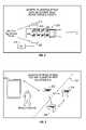
- FIG. 2shows the use of an RFID tag or interrogator to interrogate the contents of a truck
- FIG. 3shows RFID tags being scanned by fixed interrogators
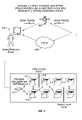
- FIG. 4shows different ways in which the RF ID tag can have its data and contents scanned and sent over long distances
- FIG. 5shows an RFID tag with modular areas for extra sensors therein.
- RFID sensorsalso called RFID “tags” have communicated typically via line of sight communication.
- a tagcommunicates directly with a remote interrogator.
- the inventorsnoticed that this creates a problem when the line of sight is blocked by some RFID attenuator material such as a metal, liquid or dampness. It also can create a problem when there is too large a distance between the tag and the interrogator.
- an active RFID devicemay relay other RFID information so that the interrogator may receive responses via relays.
- RF ID communicatorsare “meshed” to work reliably and securely even in the presence of barriers and at larger distance from interrogators.
- Each tagmay include a microcontroller 100 , communicating with an RF modem 110 .
- the RF modem 110may operate at 915 MHz, or at some other unlicensed frequency such as 433 MHz, 868 MHz or 2.4 GHz.
- Some optional sensorsmay be included such as shown by 120 , or alternatively, these can be included as part of either the microcontroller chip or the RFID chip. These other sensors may also be included. These can include temperature sensors; humidity sensors; battery condition sensors and/or shock accelerometer, for example.
- RF modem 110may include an ID 111 which may be a unique ID that identifies the RFID tag to all other aspects of the system.
- the RFID address 111may be a unique number, that represents the RFID tag.
- the interrogatormay be precisely the same as the first tag 99 , however, the interrogator 130 may operate from line power shown as 131 instead of from the battery power shown as 105 .
- the interrogatormay also include an ethernet port 132 to report the received data.
- FIG. 1also shows an additional RFID tag 140 which is blocked or partially blocked by an obstruction 145 .
- the interrogator 130may attempt to read the information from the RFID tag 140 . However, it is unable to do so because of the barrier 145 .
- RFID tag 140communicates with RFID tag 150 . When the interrogator polls 150 it receives the information from both the RFID tag 140 and also from RFID tag 150 .
- the microcontroller 100controls the modem 110 to receive all tags within range, and to send, responsive to a interrogation, information about all the RFID tags within range as well as its own information.
- the systemmay use deterministic techniques to forward the message—broadcast routing or flooding routing to forward the information.
- probabilistic routingcan be used.
- the node xwhen the node x receives a broadcast message from another node y, it computes distance from x to y based on signal strength, propagation model and transmission power, area and signal strength, and uses a base probability p to decide how to rebroadcast the message with a real probability p′, according to a function of all these parameters. This can minimize the amount of retransmission.
- FIG. 2shows a first scenario, where items arriving at a base are scanned while driving through portals.
- FIG. 2shows a truck 200 arriving through a “portal”.
- the portalincludes two different sensors 205 , 210 .
- each of the many different tags such as 220are interrogated by the portal, either directly, or through a proxy.
- the truckmay include a special proxy tag 225 located extending through the wall of the truck.
- This proxy tagmay be another tag assembly like 99 that relays the information received from inside the truck bed to the scanner such as 210 .
- FIG. 3illustrates another embodiment, where tags are scanned by fixed interrogators.
- a fixed interrogator 300may scan any of the tag such as 302 , 304 , 306 .
- both 304 and 306are outside of the lines 310 which represents the outer limits of scanning of the interrogator 300 . Both of these are scanned via interaction with the tag 302 .
- FIG. 4illustrates an alternative embodiment in which a general monitoring station 400 may monitor the tags over a channel.
- 402illustrates the channel being a satellite while 404 illustrates the channel being the Internet.
- the monitoringmay be done by an interrogator 410 , which can interrogate directly such as it does with 412 , or through a proxy such as 414 in the presence of a metal or liquid barrier 416 .
- the systemmay require less infrastructure in terms of readers and antennas.
- Tag IDs that are out of range of a readercan still be received by a reader field relay from other tags.
- the systemis also more robust in terms of tag read rates and missed tags in current systems. This is because multiple tags like these are received by the reader via multiple diverse paths.
- tags on the inside of the pallet or casemay be shielded from the direct line of sight to the reader.
- tags on the insidereach tags on the outside which do have line of sight. Their IDs are relayed to the reader.
- each tagis both a transmitter and receiver
- the systemcan be made very secure by using challenge response encryption protocols. This allows the tag IDs to be verified as being genuine, and to verify that the system is not being spoofed. Also, since each tag inherently has an address, the tags can be read multiple times, from multiple different directions. This ability to read everything multiple times causes nearly 100% read rates with nearly 100% accuracy.
- FIG. 5Another embodiment, shown in FIG. 5 , allows the tags to have a new modular design.
- a battery, 500 , controller 502 , and RFID modem 504may be the core elements in the system.
- An “open bus” designleaves spaces on the tag's surface itself. There may be one or more of such spaces; FIG. 5 , for example shows five surfaces 510 , 512 , 514 . These surface may include areas where items can be pressed in, or they may be areas for items that can be assembled with as part of the tag.
- the tags spotscan include any of the sensors described above.
- the tagscan be adhesive backed or simply plastic substrates of any given kind.
Landscapes
- Physics & Mathematics (AREA)
- Engineering & Computer Science (AREA)
- Automation & Control Theory (AREA)
- Computer Security & Cryptography (AREA)
- Electromagnetism (AREA)
- General Physics & Mathematics (AREA)
- Near-Field Transmission Systems (AREA)
Abstract
Description
Claims (14)
Priority Applications (1)
| Application Number | Priority Date | Filing Date | Title |
|---|---|---|---|
| US12/236,455US8094022B2 (en) | 2007-09-25 | 2008-09-23 | Active ID tags for increased range and functionality |
Applications Claiming Priority (2)
| Application Number | Priority Date | Filing Date | Title |
|---|---|---|---|
| US97511207P | 2007-09-25 | 2007-09-25 | |
| US12/236,455US8094022B2 (en) | 2007-09-25 | 2008-09-23 | Active ID tags for increased range and functionality |
Publications (2)
| Publication Number | Publication Date |
|---|---|
| US20090102656A1 US20090102656A1 (en) | 2009-04-23 |
| US8094022B2true US8094022B2 (en) | 2012-01-10 |
Family
ID=40562936
Family Applications (1)
| Application Number | Title | Priority Date | Filing Date |
|---|---|---|---|
| US12/236,455Active - Reinstated2030-01-21US8094022B2 (en) | 2007-09-25 | 2008-09-23 | Active ID tags for increased range and functionality |
Country Status (1)
| Country | Link |
|---|---|
| US (1) | US8094022B2 (en) |
Cited By (2)
| Publication number | Priority date | Publication date | Assignee | Title |
|---|---|---|---|---|
| US10417626B1 (en)* | 2018-05-02 | 2019-09-17 | Capital One Services, Llc | Secure contactless payment method and device with active electronic circuitry |
| US11213773B2 (en) | 2017-03-06 | 2022-01-04 | Cummins Filtration Ip, Inc. | Genuine filter recognition with filter monitoring system |
Families Citing this family (5)
| Publication number | Priority date | Publication date | Assignee | Title |
|---|---|---|---|---|
| US9881250B2 (en)* | 2013-06-07 | 2018-01-30 | Fisher Controls International Llc | Methods and apparatus for RFID communications in a process control system |
| US20150179029A1 (en)* | 2013-12-20 | 2015-06-25 | Glow Motion Technologies | Method and system for patterning elements having two states |
| US10303134B2 (en) | 2015-04-10 | 2019-05-28 | Fisher Controls International Llc | Methods and apparatus for multimode RFST communications in process control systems |
| US10019886B2 (en)* | 2016-01-22 | 2018-07-10 | Aktiebolaget Skf | Sticker, condition monitoring system, method and computer program product |
| US20170213118A1 (en)* | 2016-01-22 | 2017-07-27 | Aktiebolaget Skf | Sticker, condition monitoring system, method & computer program product |
Citations (10)
| Publication number | Priority date | Publication date | Assignee | Title |
|---|---|---|---|---|
| US5804810A (en)* | 1996-06-26 | 1998-09-08 | Par Government Systems Corporation | Communicating with electronic tags |
| US5892441A (en)* | 1996-06-26 | 1999-04-06 | Par Government Systems Corporation | Sensing with active electronic tags |
| US6972682B2 (en)* | 2002-01-18 | 2005-12-06 | Georgia Tech Research Corporation | Monitoring and tracking of assets by utilizing wireless communications |
| US7145451B2 (en)* | 1999-07-20 | 2006-12-05 | Avid Identification Systems, Inc. | Impedance matching network and multidimensional electromagnetic field coil for a transponder interrogator |
| US7199716B2 (en)* | 2001-02-12 | 2007-04-03 | Symbol Technologies, Inc. | Method, system, and apparatus for communicating with a RFID tag population |
| US20070252696A1 (en)* | 2006-05-01 | 2007-11-01 | Belisle Timothy F | Geo-location system, method and apparatus |
| US7295114B1 (en)* | 2005-01-21 | 2007-11-13 | Alien Technology Corporation | Location management for radio frequency identification readers |
| US20080122610A1 (en)* | 2000-01-24 | 2008-05-29 | Nextreme L.L.C. | RF-enabled pallet |
| US20080211630A1 (en)* | 2005-12-09 | 2008-09-04 | Butler Timothy P | Multiple radio frequency network node rfid tag |
| US20080244739A1 (en)* | 2007-03-30 | 2008-10-02 | Zhen Liu | Method and system for resilient packet traceback in wireless mesh and sensor networks |
Family Cites Families (4)
| Publication number | Priority date | Publication date | Assignee | Title |
|---|---|---|---|---|
| US5604468A (en)* | 1996-04-22 | 1997-02-18 | Motorola, Inc. | Frequency synthesizer with temperature compensation and frequency multiplication and method of providing the same |
| US5781073A (en)* | 1996-07-24 | 1998-07-14 | Mii; Adam | Temperature compensation method for an output frequency drift of an oscillator |
| JP2005311945A (en)* | 2004-04-26 | 2005-11-04 | Matsushita Electric Ind Co Ltd | PLL circuit, wireless communication apparatus, and oscillation frequency control method |
| US7154305B2 (en)* | 2004-12-22 | 2006-12-26 | Alcatel | Periodic electrical signal frequency monitoring systems and methods |
- 2008
- 2008-09-23USUS12/236,455patent/US8094022B2/enactiveActive - Reinstated
Patent Citations (10)
| Publication number | Priority date | Publication date | Assignee | Title |
|---|---|---|---|---|
| US5804810A (en)* | 1996-06-26 | 1998-09-08 | Par Government Systems Corporation | Communicating with electronic tags |
| US5892441A (en)* | 1996-06-26 | 1999-04-06 | Par Government Systems Corporation | Sensing with active electronic tags |
| US7145451B2 (en)* | 1999-07-20 | 2006-12-05 | Avid Identification Systems, Inc. | Impedance matching network and multidimensional electromagnetic field coil for a transponder interrogator |
| US20080122610A1 (en)* | 2000-01-24 | 2008-05-29 | Nextreme L.L.C. | RF-enabled pallet |
| US7199716B2 (en)* | 2001-02-12 | 2007-04-03 | Symbol Technologies, Inc. | Method, system, and apparatus for communicating with a RFID tag population |
| US6972682B2 (en)* | 2002-01-18 | 2005-12-06 | Georgia Tech Research Corporation | Monitoring and tracking of assets by utilizing wireless communications |
| US7295114B1 (en)* | 2005-01-21 | 2007-11-13 | Alien Technology Corporation | Location management for radio frequency identification readers |
| US20080211630A1 (en)* | 2005-12-09 | 2008-09-04 | Butler Timothy P | Multiple radio frequency network node rfid tag |
| US20070252696A1 (en)* | 2006-05-01 | 2007-11-01 | Belisle Timothy F | Geo-location system, method and apparatus |
| US20080244739A1 (en)* | 2007-03-30 | 2008-10-02 | Zhen Liu | Method and system for resilient packet traceback in wireless mesh and sensor networks |
Cited By (2)
| Publication number | Priority date | Publication date | Assignee | Title |
|---|---|---|---|---|
| US11213773B2 (en) | 2017-03-06 | 2022-01-04 | Cummins Filtration Ip, Inc. | Genuine filter recognition with filter monitoring system |
| US10417626B1 (en)* | 2018-05-02 | 2019-09-17 | Capital One Services, Llc | Secure contactless payment method and device with active electronic circuitry |
Also Published As
| Publication number | Publication date |
|---|---|
| US20090102656A1 (en) | 2009-04-23 |
Similar Documents
| Publication | Publication Date | Title |
|---|---|---|
| US8094022B2 (en) | Active ID tags for increased range and functionality | |
| US6853294B1 (en) | Networking applications for automated data collection | |
| EP1867053B1 (en) | Synchronized relayed transmissions in rfid networks | |
| US7796944B2 (en) | Communication system for dynamic management of a plurality of objects and method therefor | |
| US11978015B1 (en) | Continuous inventory management | |
| US6917291B2 (en) | Interrogation, monitoring and data exchange using RFID tags | |
| JP5415598B2 (en) | Radio frequency identification system | |
| JP4107966B2 (en) | Signaling system and transponder for the system | |
| US7433648B2 (en) | System and a node used in the system for wireless communication and sensory monitoring | |
| US7394372B2 (en) | Method and apparatus for aggregating and communicating tracking information | |
| US8665072B2 (en) | Electronic monitoring systems, shipment container monitoring systems and methods of monitoring a shipment in a container | |
| US20060253590A1 (en) | Platform and methods for continuous asset location tracking and monitoring in intermittently connected environments | |
| US20060250249A1 (en) | Self describing RFID chains to validate parts in bills-of-material or manifest when disconnected from server | |
| JP2010502951A (en) | ID Doppler movement detector | |
| CA2594997C (en) | Method for monitoring a group of objects and associated arrangement | |
| US20040246104A1 (en) | Method for monitoring goods | |
| JP5440893B2 (en) | Information processing apparatus, information processing method, reflector, and communication system | |
| US20100232320A1 (en) | Wireless data communications network system for tracking container | |
| US8766777B2 (en) | RFID marking of units in a space | |
| CN101501739B (en) | Autonomous interrogating transponder for direct communications with other transponders | |
| WO2022032336A1 (en) | Tracking device and system | |
| US20100164687A1 (en) | Rfid reader and identification method for identifying the same | |
| KR101689349B1 (en) | Logistics IoT communication system and method supporting bidirectional communication | |
| JP2009163733A (en) | Rfid tag detection method and system | |
| KR101272405B1 (en) | System and device for container security based on multi hop |
Legal Events
| Date | Code | Title | Description |
|---|---|---|---|
| AS | Assignment | Owner name:INFINID TECHNOLOGIES, INC, CALIFORNIA Free format text:ASSIGNMENT OF ASSIGNORS INTEREST;ASSIGNORS:GOODMAN, RODNEY M;AMBROSE, BARRY EDWARD;REEL/FRAME:022065/0854 Effective date:20080924 | |
| AS | Assignment | Owner name:US GOVERNMENT - SECRETARY FOR THE ARMY, MARYLAND Free format text:CONFIRMATORY LICENSE;ASSIGNOR:INFINID TECHNOLOGIES INC.;REEL/FRAME:023568/0347 Effective date:20091028 | |
| REMI | Maintenance fee reminder mailed | ||
| LAPS | Lapse for failure to pay maintenance fees | ||
| FP | Lapsed due to failure to pay maintenance fee | Effective date:20160110 | |
| FEPP | Fee payment procedure | Free format text:PETITION RELATED TO MAINTENANCE FEES FILED (ORIGINAL EVENT CODE: PMFP) | |
| PRDP | Patent reinstated due to the acceptance of a late maintenance fee | Effective date:20181005 | |
| FEPP | Fee payment procedure | Free format text:PETITION RELATED TO MAINTENANCE FEES GRANTED (ORIGINAL EVENT CODE: PMFG); ENTITY STATUS OF PATENT OWNER: SMALL ENTITY Free format text:SURCHARGE, PETITION TO ACCEPT PYMT AFTER EXP, UNINTENTIONAL. (ORIGINAL EVENT CODE: M2558); ENTITY STATUS OF PATENT OWNER: SMALL ENTITY | |
| MAFP | Maintenance fee payment | Free format text:PAYMENT OF MAINTENANCE FEE, 4TH YR, SMALL ENTITY (ORIGINAL EVENT CODE: M2551); ENTITY STATUS OF PATENT OWNER: SMALL ENTITY Year of fee payment:4 | |
| STCF | Information on status: patent grant | Free format text:PATENTED CASE | |
| MAFP | Maintenance fee payment | Free format text:PAYMENT OF MAINTENANCE FEE, 8TH YR, SMALL ENTITY (ORIGINAL EVENT CODE: M2552); ENTITY STATUS OF PATENT OWNER: SMALL ENTITY Year of fee payment:8 | |
| MAFP | Maintenance fee payment | Free format text:PAYMENT OF MAINTENANCE FEE, 12TH YR, SMALL ENTITY (ORIGINAL EVENT CODE: M2553); ENTITY STATUS OF PATENT OWNER: SMALL ENTITY Year of fee payment:12 |