US8094009B2 - Health-related signaling via wearable items - Google Patents
Health-related signaling via wearable itemsDownload PDFInfo
- Publication number
- US8094009B2 US8094009B2US12/231,061US23106108AUS8094009B2US 8094009 B2US8094009 B2US 8094009B2US 23106108 AUS23106108 AUS 23106108AUS 8094009 B2US8094009 B2US 8094009B2
- Authority
- US
- United States
- Prior art keywords
- circuitry
- healthcare recipient
- body part
- peripheral body
- information indicating
- Prior art date
- Legal status (The legal status is an assumption and is not a legal conclusion. Google has not performed a legal analysis and makes no representation as to the accuracy of the status listed.)
- Active, expires
Links
- 230000011664signalingEffects0.000titleclaimsdescription79
- 230000036541healthEffects0.000titleclaimsdescription60
- 230000002093peripheral effectEffects0.000claimsdescription198
- 230000004044responseEffects0.000claimsdescription116
- 230000003287optical effectEffects0.000claimsdescription21
- 230000015556catabolic processEffects0.000claimsdescription12
- 239000003814drugSubstances0.000claimsdescription11
- 230000002159abnormal effectEffects0.000claimsdescription10
- 230000008859changeEffects0.000claimsdescription10
- 229940079593drugDrugs0.000claimsdescription10
- 238000006731degradation reactionMethods0.000claimsdescription8
- 238000012795verificationMethods0.000claimsdescription8
- 239000003638chemical reducing agentSubstances0.000claimsdescription7
- 235000015097nutrientsNutrition0.000claimsdescription7
- 230000008961swellingEffects0.000claimsdescription7
- 238000000034methodMethods0.000abstractdescription110
- 238000001514detection methodMethods0.000description44
- 238000005259measurementMethods0.000description30
- 230000008569processEffects0.000description30
- 238000004891communicationMethods0.000description25
- 230000003993interactionEffects0.000description24
- 238000012544monitoring processMethods0.000description24
- 238000005516engineering processMethods0.000description22
- 210000003414extremityAnatomy0.000description19
- 238000012545processingMethods0.000description18
- 239000012530fluidSubstances0.000description17
- 210000001519tissueAnatomy0.000description17
- 230000005540biological transmissionEffects0.000description13
- 230000000694effectsEffects0.000description13
- 230000033001locomotionEffects0.000description13
- 238000011156evaluationMethods0.000description11
- 238000004590computer programMethods0.000description10
- 208000024891symptomDiseases0.000description9
- 230000001225therapeutic effectEffects0.000description9
- 239000000853adhesiveSubstances0.000description8
- 230000001070adhesive effectEffects0.000description8
- 238000004821distillationMethods0.000description8
- 230000007170pathologyEffects0.000description8
- 238000009826distributionMethods0.000description7
- 230000036407painEffects0.000description7
- 238000004458analytical methodMethods0.000description6
- 239000000470constituentSubstances0.000description6
- 230000006870functionEffects0.000description6
- 238000003384imaging methodMethods0.000description6
- 230000009885systemic effectEffects0.000description6
- 210000004369bloodAnatomy0.000description5
- 239000008280bloodSubstances0.000description5
- 238000013461designMethods0.000description5
- 230000000670limiting effectEffects0.000description5
- 238000003860storageMethods0.000description5
- CURLTUGMZLYLDI-UHFFFAOYSA-NCarbon dioxideChemical compoundO=C=OCURLTUGMZLYLDI-UHFFFAOYSA-N0.000description4
- 210000004204blood vesselAnatomy0.000description4
- 230000036760body temperatureEffects0.000description4
- 238000001816coolingMethods0.000description4
- 230000007423decreaseEffects0.000description4
- 230000001419dependent effectEffects0.000description4
- 238000003745diagnosisMethods0.000description4
- 230000007613environmental effectEffects0.000description4
- 239000007788liquidSubstances0.000description4
- 239000000463materialSubstances0.000description4
- 238000012986modificationMethods0.000description4
- 230000004048modificationEffects0.000description4
- 244000052769pathogenSpecies0.000description4
- 230000005855radiationEffects0.000description4
- 238000011160researchMethods0.000description4
- 230000029058respiratory gaseous exchangeEffects0.000description4
- 238000005070samplingMethods0.000description4
- 238000001931thermographyMethods0.000description4
- 208000007536ThrombosisDiseases0.000description3
- 230000004075alterationEffects0.000description3
- 230000036772blood pressureEffects0.000description3
- 230000004087circulationEffects0.000description3
- 230000036757core body temperatureEffects0.000description3
- 238000010586diagramMethods0.000description3
- 230000008030eliminationEffects0.000description3
- 238000003379elimination reactionMethods0.000description3
- 238000000605extractionMethods0.000description3
- 238000001914filtrationMethods0.000description3
- 230000002452interceptive effectEffects0.000description3
- 230000002503metabolic effectEffects0.000description3
- 238000010606normalizationMethods0.000description3
- 230000001575pathological effectEffects0.000description3
- 231100000241scarToxicity0.000description3
- 239000000126substanceSubstances0.000description3
- 206010002091AnaesthesiaDiseases0.000description2
- 241000894006BacteriaSpecies0.000description2
- 206010004950Birth markDiseases0.000description2
- OYPRJOBELJOOCE-UHFFFAOYSA-NCalciumChemical compound[Ca]OYPRJOBELJOOCE-UHFFFAOYSA-N0.000description2
- 206010053567CoagulopathiesDiseases0.000description2
- WQZGKKKJIJFFOK-GASJEMHNSA-NGlucoseNatural productsOC[C@H]1OC(O)[C@H](O)[C@@H](O)[C@@H]1OWQZGKKKJIJFFOK-GASJEMHNSA-N0.000description2
- DGAQECJNVWCQMB-PUAWFVPOSA-MIlexoside XXIXChemical compoundC[C@@H]1CC[C@@]2(CC[C@@]3(C(=CC[C@H]4[C@]3(CC[C@@H]5[C@@]4(CC[C@@H](C5(C)C)OS(=O)(=O)[O-])C)C)[C@@H]2[C@]1(C)O)C)C(=O)O[C@H]6[C@@H]([C@H]([C@@H]([C@H](O6)CO)O)O)O.[Na+]DGAQECJNVWCQMB-PUAWFVPOSA-M0.000description2
- 206010061218InflammationDiseases0.000description2
- 208000027418Wounds and injuryDiseases0.000description2
- 230000004913activationEffects0.000description2
- 230000003044adaptive effectEffects0.000description2
- 230000002776aggregationEffects0.000description2
- 238000004220aggregationMethods0.000description2
- 230000037005anaesthesiaEffects0.000description2
- 238000001949anaesthesiaMethods0.000description2
- 238000003491arrayMethods0.000description2
- 210000001367arteryAnatomy0.000description2
- 238000013475authorizationMethods0.000description2
- 230000008901benefitEffects0.000description2
- 230000017531blood circulationEffects0.000description2
- 210000000988bone and boneAnatomy0.000description2
- 239000011575calciumSubstances0.000description2
- 229910052791calciumInorganic materials0.000description2
- 229910002092carbon dioxideInorganic materials0.000description2
- 239000001569carbon dioxideSubstances0.000description2
- HVYWMOMLDIMFJA-DPAQBDIFSA-NcholesterolChemical compoundC1C=C2C[C@@H](O)CC[C@]2(C)[C@@H]2[C@@H]1[C@@H]1CC[C@H]([C@H](C)CCCC(C)C)[C@@]1(C)CC2HVYWMOMLDIMFJA-DPAQBDIFSA-N0.000description2
- 230000035602clottingEffects0.000description2
- 238000010276constructionMethods0.000description2
- 230000002596correlated effectEffects0.000description2
- 238000007405data analysisMethods0.000description2
- 238000013481data captureMethods0.000description2
- 238000013075data extractionMethods0.000description2
- 238000002059diagnostic imagingMethods0.000description2
- 238000002845discolorationMethods0.000description2
- 239000000835fiberSubstances0.000description2
- 239000007789gasSubstances0.000description2
- 239000008103glucoseSubstances0.000description2
- 230000003862health statusEffects0.000description2
- 230000001771impaired effectEffects0.000description2
- 230000004054inflammatory processEffects0.000description2
- NOESYZHRGYRDHS-UHFFFAOYSA-NinsulinChemical compoundN1C(=O)C(NC(=O)C(CCC(N)=O)NC(=O)C(CCC(O)=O)NC(=O)C(C(C)C)NC(=O)C(NC(=O)CN)C(C)CC)CSSCC(C(NC(CO)C(=O)NC(CC(C)C)C(=O)NC(CC=2C=CC(O)=CC=2)C(=O)NC(CCC(N)=O)C(=O)NC(CC(C)C)C(=O)NC(CCC(O)=O)C(=O)NC(CC(N)=O)C(=O)NC(CC=2C=CC(O)=CC=2)C(=O)NC(CSSCC(NC(=O)C(C(C)C)NC(=O)C(CC(C)C)NC(=O)C(CC=2C=CC(O)=CC=2)NC(=O)C(CC(C)C)NC(=O)C(C)NC(=O)C(CCC(O)=O)NC(=O)C(C(C)C)NC(=O)C(CC(C)C)NC(=O)C(CC=2NC=NC=2)NC(=O)C(CO)NC(=O)CNC2=O)C(=O)NCC(=O)NC(CCC(O)=O)C(=O)NC(CCCNC(N)=N)C(=O)NCC(=O)NC(CC=3C=CC=CC=3)C(=O)NC(CC=3C=CC=CC=3)C(=O)NC(CC=3C=CC(O)=CC=3)C(=O)NC(C(C)O)C(=O)N3C(CCC3)C(=O)NC(CCCCN)C(=O)NC(C)C(O)=O)C(=O)NC(CC(N)=O)C(O)=O)=O)NC(=O)C(C(C)CC)NC(=O)C(CO)NC(=O)C(C(C)O)NC(=O)C1CSSCC2NC(=O)C(CC(C)C)NC(=O)C(NC(=O)C(CCC(N)=O)NC(=O)C(CC(N)=O)NC(=O)C(NC(=O)C(N)CC=1C=CC=CC=1)C(C)C)CC1=CN=CN1NOESYZHRGYRDHS-UHFFFAOYSA-N0.000description2
- 150000002500ionsChemical class0.000description2
- 210000002414legAnatomy0.000description2
- 230000007246mechanismEffects0.000description2
- 230000004060metabolic processEffects0.000description2
- 230000000116mitigating effectEffects0.000description2
- 238000011002quantificationMethods0.000description2
- 239000000523sampleSubstances0.000description2
- 239000004065semiconductorSubstances0.000description2
- 239000011734sodiumSubstances0.000description2
- 229910052708sodiumInorganic materials0.000description2
- 238000002560therapeutic procedureMethods0.000description2
- 238000002604ultrasonographyMethods0.000description2
- 210000002700urineAnatomy0.000description2
- 206010002329AneurysmDiseases0.000description1
- 208000017667Chronic DiseaseDiseases0.000description1
- 206010061818Disease progressionDiseases0.000description1
- 206010013887DysarthriaDiseases0.000description1
- 239000004606Fillers/ExtendersSubstances0.000description1
- 208000010412GlaucomaDiseases0.000description1
- 206010019280Heart failuresDiseases0.000description1
- 102000001554HemoglobinsHuman genes0.000description1
- 108010054147HemoglobinsProteins0.000description1
- 108090001061InsulinProteins0.000description1
- 102000004877InsulinHuman genes0.000description1
- 102000007474Multiprotein ComplexesHuman genes0.000description1
- 108010085220Multiprotein ComplexesProteins0.000description1
- ZLMJMSJWJFRBEC-UHFFFAOYSA-NPotassiumChemical compound[K]ZLMJMSJWJFRBEC-UHFFFAOYSA-N0.000description1
- 208000004210Pressure UlcerDiseases0.000description1
- 241001611093StimulaSpecies0.000description1
- 208000003028StutteringDiseases0.000description1
- 206010046543Urinary incontinenceDiseases0.000description1
- 241000700605VirusesSpecies0.000description1
- 230000005856abnormalityEffects0.000description1
- 239000008186active pharmaceutical agentSubstances0.000description1
- 208000026935allergic diseaseDiseases0.000description1
- 230000006793arrhythmiaEffects0.000description1
- 206010003119arrhythmiaDiseases0.000description1
- QVGXLLKOCUKJST-UHFFFAOYSA-Natomic oxygenChemical compound[O]QVGXLLKOCUKJST-UHFFFAOYSA-N0.000description1
- 210000000941bileAnatomy0.000description1
- 210000000013bile ductAnatomy0.000description1
- 102000023732binding proteinsHuman genes0.000description1
- 108091008324binding proteinsProteins0.000description1
- 239000012867bioactive agentSubstances0.000description1
- 230000031018biological processes and functionsEffects0.000description1
- 238000009530blood pressure measurementMethods0.000description1
- 238000009529body temperature measurementMethods0.000description1
- 230000007177brain activityEffects0.000description1
- 239000000872bufferSubstances0.000description1
- 244000309466calfSpecies0.000description1
- 239000002775capsuleSubstances0.000description1
- 210000005242cardiac chamberAnatomy0.000description1
- 239000000969carrierSubstances0.000description1
- 238000005266castingMethods0.000description1
- 210000004027cellAnatomy0.000description1
- 239000003795chemical substances by applicationSubstances0.000description1
- 235000012000cholesterolNutrition0.000description1
- 239000003086colorantSubstances0.000description1
- 230000000052comparative effectEffects0.000description1
- 206010010121compartment syndromeDiseases0.000description1
- 239000002131composite materialSubstances0.000description1
- 238000012790confirmationMethods0.000description1
- 230000001276controlling effectEffects0.000description1
- 208000029078coronary artery diseaseDiseases0.000description1
- 230000000875corresponding effectEffects0.000description1
- 230000000537coughlike effectEffects0.000description1
- 230000008878couplingEffects0.000description1
- 238000010168coupling processMethods0.000description1
- 238000005859coupling reactionMethods0.000description1
- 239000013078crystalSubstances0.000description1
- 230000006378damageEffects0.000description1
- 238000007418data miningMethods0.000description1
- 230000003247decreasing effectEffects0.000description1
- 208000002925dental cariesDiseases0.000description1
- 230000010339dilationEffects0.000description1
- 230000008034disappearanceEffects0.000description1
- 201000010099diseaseDiseases0.000description1
- 230000005750disease progressionEffects0.000description1
- 208000037265diseases, disorders, signs and symptomsDiseases0.000description1
- 229940088679drug related substanceDrugs0.000description1
- 230000009977dual effectEffects0.000description1
- 210000000624ear auricleAnatomy0.000description1
- 230000005684electric fieldEffects0.000description1
- 239000003792electrolyteSubstances0.000description1
- 210000003743erythrocyteAnatomy0.000description1
- 238000011066ex-situ storageMethods0.000description1
- 230000001747exhibiting effectEffects0.000description1
- 230000012010growthEffects0.000description1
- 230000005802health problemEffects0.000description1
- 238000010438heat treatmentMethods0.000description1
- 208000011316hemodynamic instabilityDiseases0.000description1
- 239000007943implantSubstances0.000description1
- 230000006872improvementEffects0.000description1
- 230000002757inflammatory effectEffects0.000description1
- 230000005764inhibitory processEffects0.000description1
- 208000014674injuryDiseases0.000description1
- 229940125396insulinDrugs0.000description1
- 208000016339iris patternDiseases0.000description1
- 210000000265leukocyteAnatomy0.000description1
- 239000004973liquid crystal related substanceSubstances0.000description1
- 230000003137locomotive effectEffects0.000description1
- 210000004072lungAnatomy0.000description1
- 230000014759maintenance of locationEffects0.000description1
- 238000007726management methodMethods0.000description1
- 238000004519manufacturing processMethods0.000description1
- 238000013507mappingMethods0.000description1
- 238000002483medicationMethods0.000description1
- 239000003595mistSubstances0.000description1
- 239000003607modifierSubstances0.000description1
- 210000005036nerveAnatomy0.000description1
- 230000004007neuromodulationEffects0.000description1
- 230000003957neurotransmitter releaseEffects0.000description1
- 230000001151other effectEffects0.000description1
- 229910052760oxygenInorganic materials0.000description1
- 239000001301oxygenSubstances0.000description1
- 238000006213oxygenation reactionMethods0.000description1
- 206010033675panniculitisDiseases0.000description1
- 230000036961partial effectEffects0.000description1
- 230000001717pathogenic effectEffects0.000description1
- 238000003909pattern recognitionMethods0.000description1
- 230000007406plaque accumulationEffects0.000description1
- 239000011591potassiumSubstances0.000description1
- 229910052700potassiumInorganic materials0.000description1
- 230000003334potential effectEffects0.000description1
- 238000007639printingMethods0.000description1
- 238000004393prognosisMethods0.000description1
- 102000004169proteins and genesHuman genes0.000description1
- 108090000623proteins and genesProteins0.000description1
- 238000001671psychotherapyMethods0.000description1
- 239000012857radioactive materialSubstances0.000description1
- 238000002601radiographyMethods0.000description1
- 238000007670refiningMethods0.000description1
- 238000009877renderingMethods0.000description1
- 230000000717retained effectEffects0.000description1
- 230000002441reversible effectEffects0.000description1
- 238000012216screeningMethods0.000description1
- 238000004088simulationMethods0.000description1
- 208000026473slurred speechDiseases0.000description1
- 238000001179sorption measurementMethods0.000description1
- 239000007921spraySubstances0.000description1
- 238000007920subcutaneous administrationMethods0.000description1
- 210000004304subcutaneous tissueAnatomy0.000description1
- 239000000758substrateSubstances0.000description1
- 230000000153supplemental effectEffects0.000description1
- 210000004243sweatAnatomy0.000description1
- 230000002123temporal effectEffects0.000description1
- 238000012360testing methodMethods0.000description1
- 229940124597therapeutic agentDrugs0.000description1
- 230000004797therapeutic responseEffects0.000description1
- 239000010409thin filmSubstances0.000description1
- 230000036962time dependentEffects0.000description1
- 230000001131transforming effectEffects0.000description1
- 238000013519translationMethods0.000description1
- 238000002834transmittanceMethods0.000description1
- 210000000689upper legAnatomy0.000description1
- 210000003708urethraAnatomy0.000description1
- 210000005166vasculatureAnatomy0.000description1
- 210000003462veinAnatomy0.000description1
- 230000000007visual effectEffects0.000description1
- 230000001755vocal effectEffects0.000description1
- 238000005406washingMethods0.000description1
Images


Classifications
- A—HUMAN NECESSITIES
- A61—MEDICAL OR VETERINARY SCIENCE; HYGIENE
- A61B—DIAGNOSIS; SURGERY; IDENTIFICATION
- A61B5/00—Measuring for diagnostic purposes; Identification of persons
- A61B5/68—Arrangements of detecting, measuring or recording means, e.g. sensors, in relation to patient
- A61B5/6801—Arrangements of detecting, measuring or recording means, e.g. sensors, in relation to patient specially adapted to be attached to or worn on the body surface
- A61B5/683—Means for maintaining contact with the body
- A61B5/6832—Means for maintaining contact with the body using adhesives
- A61B5/6833—Adhesive patches
- A—HUMAN NECESSITIES
- A61—MEDICAL OR VETERINARY SCIENCE; HYGIENE
- A61B—DIAGNOSIS; SURGERY; IDENTIFICATION
- A61B5/00—Measuring for diagnostic purposes; Identification of persons
- A61B5/01—Measuring temperature of body parts ; Diagnostic temperature sensing, e.g. for malignant or inflamed tissue
- A—HUMAN NECESSITIES
- A61—MEDICAL OR VETERINARY SCIENCE; HYGIENE
- A61B—DIAGNOSIS; SURGERY; IDENTIFICATION
- A61B5/00—Measuring for diagnostic purposes; Identification of persons
- A61B5/02—Detecting, measuring or recording for evaluating the cardiovascular system, e.g. pulse, heart rate, blood pressure or blood flow
- A61B5/02007—Evaluating blood vessel condition, e.g. elasticity, compliance
- A—HUMAN NECESSITIES
- A61—MEDICAL OR VETERINARY SCIENCE; HYGIENE
- A61B—DIAGNOSIS; SURGERY; IDENTIFICATION
- A61B5/00—Measuring for diagnostic purposes; Identification of persons
- A61B5/08—Measuring devices for evaluating the respiratory organs
- A61B5/0816—Measuring devices for examining respiratory frequency
- A—HUMAN NECESSITIES
- A61—MEDICAL OR VETERINARY SCIENCE; HYGIENE
- A61B—DIAGNOSIS; SURGERY; IDENTIFICATION
- A61B5/00—Measuring for diagnostic purposes; Identification of persons
- A61B5/103—Measuring devices for testing the shape, pattern, colour, size or movement of the body or parts thereof, for diagnostic purposes
- A61B5/11—Measuring movement of the entire body or parts thereof, e.g. head or hand tremor or mobility of a limb
- A61B5/1112—Global tracking of patients, e.g. by using GPS
- A—HUMAN NECESSITIES
- A61—MEDICAL OR VETERINARY SCIENCE; HYGIENE
- A61B—DIAGNOSIS; SURGERY; IDENTIFICATION
- A61B5/00—Measuring for diagnostic purposes; Identification of persons
- A61B5/20—Measuring for diagnostic purposes; Identification of persons for measuring urological functions restricted to the evaluation of the urinary system
- A61B5/202—Assessing bladder functions, e.g. incontinence assessment
- A—HUMAN NECESSITIES
- A61—MEDICAL OR VETERINARY SCIENCE; HYGIENE
- A61B—DIAGNOSIS; SURGERY; IDENTIFICATION
- A61B5/00—Measuring for diagnostic purposes; Identification of persons
- A61B5/24—Detecting, measuring or recording bioelectric or biomagnetic signals of the body or parts thereof
- A—HUMAN NECESSITIES
- A61—MEDICAL OR VETERINARY SCIENCE; HYGIENE
- A61B—DIAGNOSIS; SURGERY; IDENTIFICATION
- A61B5/00—Measuring for diagnostic purposes; Identification of persons
- A61B5/41—Detecting, measuring or recording for evaluating the immune or lymphatic systems
- A61B5/411—Detecting or monitoring allergy or intolerance reactions to an allergenic agent or substance
- A—HUMAN NECESSITIES
- A61—MEDICAL OR VETERINARY SCIENCE; HYGIENE
- A61B—DIAGNOSIS; SURGERY; IDENTIFICATION
- A61B5/00—Measuring for diagnostic purposes; Identification of persons
- A61B5/48—Other medical applications
- A61B5/4869—Determining body composition
- A61B5/4875—Hydration status, fluid retention of the body
- A—HUMAN NECESSITIES
- A61—MEDICAL OR VETERINARY SCIENCE; HYGIENE
- A61B—DIAGNOSIS; SURGERY; IDENTIFICATION
- A61B5/00—Measuring for diagnostic purposes; Identification of persons
- A61B5/68—Arrangements of detecting, measuring or recording means, e.g. sensors, in relation to patient
- A61B5/6801—Arrangements of detecting, measuring or recording means, e.g. sensors, in relation to patient specially adapted to be attached to or worn on the body surface
- A61B5/6802—Sensor mounted on worn items
- A61B5/6804—Garments; Clothes
- A—HUMAN NECESSITIES
- A61—MEDICAL OR VETERINARY SCIENCE; HYGIENE
- A61B—DIAGNOSIS; SURGERY; IDENTIFICATION
- A61B5/00—Measuring for diagnostic purposes; Identification of persons
- A61B5/68—Arrangements of detecting, measuring or recording means, e.g. sensors, in relation to patient
- A61B5/6801—Arrangements of detecting, measuring or recording means, e.g. sensors, in relation to patient specially adapted to be attached to or worn on the body surface
- A61B5/6802—Sensor mounted on worn items
- A61B5/681—Wristwatch-type devices
- A—HUMAN NECESSITIES
- A61—MEDICAL OR VETERINARY SCIENCE; HYGIENE
- A61B—DIAGNOSIS; SURGERY; IDENTIFICATION
- A61B5/00—Measuring for diagnostic purposes; Identification of persons
- A61B5/68—Arrangements of detecting, measuring or recording means, e.g. sensors, in relation to patient
- A61B5/6801—Arrangements of detecting, measuring or recording means, e.g. sensors, in relation to patient specially adapted to be attached to or worn on the body surface
- A61B5/683—Means for maintaining contact with the body
- A61B5/6831—Straps, bands or harnesses
Definitions
- a methodincludes but is not limited to obtaining information indicating a current thermal condition in a peripheral body part of the healthcare recipient and signaling a decision whether to transmit a notification at least partly in response to one or more comparisons between the information indicating the current thermal condition in the peripheral body part of the healthcare recipient and information indicating a prior thermal condition in the peripheral body part of the healthcare recipient.
- related systemsinclude but are not limited to circuitry and/or programming for effecting the herein referenced method aspects; the circuitry and/or programming can be virtually any combination of hardware, software, and/or firmware configured to effect the herein referenced method aspects depending upon the design choices of the system designer.
- a systemincludes but is not limited to circuitry for obtaining information indicating a current thermal condition in a peripheral body part of the healthcare recipient and circuitry for signaling a decision whether to transmit a notification at least partly in response to one or more comparisons between the information indicating the current thermal condition in the peripheral body part of the healthcare recipient and information indicating a prior thermal condition in the peripheral body part of the healthcare recipient.
- a systemincludes but is not limited to a positioning structure configured to be worn by a healthcare recipient; a receiver supported by the positioning structure and configured to receive a wireless signal; and a user interaction device supported by the positioning structure and configured to present at least some health-related information in a vicinity of the healthcare recipient responsive to the wireless signal.
- a systemincludes but is not limited to a positioning structure configured to be worn by a healthcare recipient; a receiver supported by the positioning structure and configured to receive a wireless signal; and an output device supported by the positioning structure and configured to transmit at least some health-related information responsive to the wireless signal and to sensor data in proximity to the healthcare recipient.
- a systemincludes but is not limited to a positioning structure configured to be worn by a healthcare recipient; a receiver supported by the positioning structure and configured to receive a wireless signal; and a first output device supported by the positioning structure and configured to transmit at least some health-related information responsive to the wireless signal and to a status update relating to the healthcare recipient.
- a systemincludes but is not limited to a positioning structure configured to be worn by a healthcare recipient; a first output device supported by the positioning structure and configured to transmit at least some health-related information in a vicinity of the healthcare recipient; and a second output device supported by the positioning structure and configured to transmit a wireless signal containing one or more scalar values indicating a position of the healthcare recipient.
- a systemincludes but is not limited to a positioning structure configured to be worn by a healthcare recipient; a movement detector supported by the positioning structure; a first output device supported by the positioning structure and configured to transmit at least a signal from the movement detector; and a second output device supported by the positioning structure and configured to transmit at least some health-related information in a vicinity of the healthcare recipient.
- related systemsinclude but are not limited to circuitry and/or programming for effecting herein-referenced method aspects; the circuitry and/or programming can be virtually any combination of hardware, software, and/or firmware configured to effect the herein-referenced method aspects depending upon the design choices of the system designer.
- circuitry and/or programmingcan be virtually any combination of hardware, software, and/or firmware configured to effect the herein-referenced method aspects depending upon the design choices of the system designer.
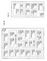
- FIGS. 1-26depict exemplary environments in which one or more technologies may be implemented.
- FIG. 27depicts a high-level logic flow of an operational process.
- FIGS. 28-29depict variants of the flow of FIG. 27 .
- an implementermay opt for a mainly hardware and/or firmware vehicle; alternatively, if flexibility is paramount, the implementer may opt for a mainly software implementation; or, yet again alternatively, the implementer may opt for some combination of hardware, software, and/or firmware.
- any vehicle to be utilizedis a choice dependent upon the context in which the vehicle will be deployed and the specific concerns (e.g., speed, flexibility, or predictability) of the implementer, any of which may vary.
- Those skilled in the artwill recognize that optical aspects of implementations will typically employ optically-oriented hardware, software, and or firmware.
- logic and similar implementationsmay include software or other control structures suitable to operation.
- Electronic circuitrymay manifest one or more paths of electrical current constructed and arranged to implement various logic functions as described herein.
- one or more mediaare configured to bear a device-detectable implementation if such media hold or transmit a special-purpose device instruction set operable to perform as described herein.
- thismay manifest as an update or other modification of existing software or firmware, or of gate arrays or other programmable hardware, such as by performing a reception of or a transmission of one or more instructions in relation to one or more operations described herein.
- an implementationmay include special-purpose hardware, software, firmware components, and/or general-purpose components executing or otherwise invoking special-purpose components. Specifications or other implementations may be transmitted by one or more instances of tangible transmission media as described herein, optionally by packet transmission or otherwise by passing through distributed media at various times.
- implementationsmay include executing a special-purpose instruction sequence or otherwise invoking circuitry for enabling, triggering, coordinating, requesting, or otherwise causing one or more occurrences of any functional operations described above.
- operational or other logical descriptions hereinmay be expressed directly as source code and compiled or otherwise invoked as an executable instruction sequence.
- C++ or other code sequencescan be compiled directly or otherwise implemented in high-level descriptor languages (e.g., a logic-synthesizable language, a hardware description language, a hardware design simulation, and/or other such similar mode(s) of expression).
- some or all of the logical expressionmay be manifested as a Verilog-type hardware description or other circuitry model before physical implementation in hardware, especially for basic operations or timing-critical applications.
- Verilog-type hardware description or other circuitry modelbefore physical implementation in hardware, especially for basic operations or timing-critical applications.
- electro-mechanical systemincludes, but is not limited to, electrical circuitry operably coupled with a transducer (e.g., an actuator, a motor, a piezoelectric crystal, a Micro Electro Mechanical System (MEMS), etc.), electrical circuitry having at least one discrete electrical circuit, electrical circuitry having at least one integrated circuit, electrical circuitry having at least one application specific integrated circuit, electrical circuitry forming a general purpose computing device configured by a computer program (e.g., a general purpose computer configured by a computer program which at least partially carries out processes and/or devices described herein, or a microprocessor configured by a computer program which at least partially carries out processes and/or devices described herein), electrical circuitry forming a memory device (e.g., forms of memory (e.g., random access, flash, read only, etc.)), electrical circuitry forming a communications device (e.g., a modem, communications switch, optical-electrical equipment, etc.), and/or any non-mechanical device.
- a transducer
- electro-mechanical systemsinclude but are not limited to a variety of consumer electronics systems, medical devices, as well as other systems such as motorized transport systems, factory automation systems, security systems, and/or communication/computing systems.
- electro-mechanical as used hereinis not necessarily limited to a system that has both electrical and mechanical actuation except as context may dictate otherwise.
- electrical circuitryincludes, but is not limited to, electrical circuitry having at least one discrete electrical circuit, electrical circuitry having at least one integrated circuit, electrical circuitry having at least one application specific integrated circuit, electrical circuitry forming a general purpose computing device configured by a computer program (e.g., a general purpose computer configured by a computer program which at least partially carries out processes and/or devices described herein, or a microprocessor configured by a computer program which at least partially carries out processes and/or devices described herein), electrical circuitry forming a memory device (e.g., forms of memory (e.g., random access, flash, read only, etc.)), and/or electrical circuitry forming a communications device (e.g.,
- a typical image processing systemmay generally include one or more of a system unit housing, a video display device, memory such as volatile or non-volatile memory, processors such as microprocessors or digital signal processors, computational entities such as operating systems, drivers, applications programs, one or more interaction devices (e.g., a touch pad, a touch screen, an antenna, etc.), control systems including feedback loops and control motors (e.g., feedback for sensing lens position and/or velocity; control motors for moving/distorting lenses to give desired focuses).
- An image processing systemmay be implemented utilizing suitable commercially available components, such as those typically found in digital still systems and/or digital motion systems.
- a data processing systemgenerally includes one or more of a system unit housing, a video display device, memory such as volatile or non-volatile memory, processors such as microprocessors or digital signal processors, computational entities such as operating systems, drivers, graphical user interfaces, and applications programs, one or more interaction devices (e.g., a touch pad, a touch screen, an antenna, etc.), and/or control systems including feedback loops and control motors (e.g., feedback for sensing position and/or velocity; control motors for moving and/or adjusting components and/or quantities).
- a data processing systemmay be implemented utilizing suitable commercially available components, such as those typically found in data computing/communication and/or network computing/communication systems.
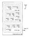
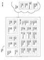
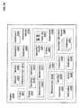
- System 100may include a wearable interface or other positioning structure 160 effective for positioning instances of detection logic 120 , devices 130 for transmitting signals 170 about a physiological or other health issue, or other components near a healthcare recipient.
- Detection logic 120may include one or more instances of symptom or event detection modules 104 , accelerometers 105 , or other sensors 106 ; positional coordinates 107 or other scalar values 108 ; or receivers 116 , 117 or other modules 118 , 119 .
- Interface 130may include one or more keypads 123 or other input devices 124 , touchscreens 125 , or other input or output devices 126 .
- a system 200comprising a sleeve, wrap, cuff, or other such layer 280 wearable by a healthcare recipient 290 and configured to present health-related information 240 obtained from or otherwise responsive to radio frequency or other signals 270 .
- layer 280may implement a positioning structure like that of FIG. 1 .
- a first embodimentprovides (a) wearable display layer 280 or other positioning structure 160 and (b) one or more touch screens 125 or other input and/or output devices supported by the positioning structure 160 and configured to present medication reminders, procedural explanations, scheduling data, or other health-related information 240 in a vicinity of a healthcare recipient 290 .
- one or more output devices 126may likewise be supported by the positioning structure 160 and configured to transmit a wireless or other signal 170 containing a distance measurement or other scalar value 108 indicating a past or current position of the healthcare recipient.
- Another embodimentprovides a positioning structure 160 configured to be worn by a healthcare recipient 290 , one or more receivers 117 supported by the positioning structure 160 and configured to receive a wireless or other signal 270 , and one or more output devices 126 supported by the positioning structure 160 and configured to present a scalar value 108 or other health-related information 240 responsive to signal 270 and to one or more status updates (from a sensor 106 , another receiver 116 , or other input devices, e.g.) relating to healthcare recipient 290 .
- Yet another embodimentprovides a positioning structure 160 configured to be worn by a healthcare recipient 290 , one or more receivers 116 , 117 supported by the positioning structure 160 and configured to receive signal 270 , and one or more touch screens 125 or other user interaction devices 130 supported by the positioning structure 160 and configured to present a care provider's location, a prescription status, or other health-related information 240 in a vicinity of the healthcare recipient 290 responsive to signal 270 .
- a positioning structure 160configured to be worn by a healthcare recipient 290 , one or more receivers 116 , 117 supported by the positioning structure 160 and configured to receive signal 270 , and one or more touch screens 125 or other user interaction devices 130 supported by the positioning structure 160 and configured to present a care provider's location, a prescription status, or other health-related information 240 in a vicinity of the healthcare recipient 290 responsive to signal 270 .
- Other such embodimentsare described below with reference to FIGS. 3-26 .
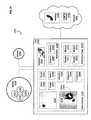
- Stationary module 340may include memory 325 or one or more modules 331 , 332 of response logic 335 configured to handle one or more signals 320 comprising health-related information 316 and/or other notifications 315 .
- signalsmay include parametric improvements or other such positive messages 311 , medical research 312 , updates, explanations, responses to inquiries, or other such data 365 suitable for presentation (via user interface 362 , e.g.) to a healthcare recipient.
- Portable module 370may include one or more transceivers or other receivers 351 , sensors 353 for obtaining measurements or other sensor data 352 , or output devices 361 as described herein.
- An embodimentprovides a positioning structure or other portable module 370 configured to be worn by a healthcare recipient; one or more receivers 351 supported by the positioning structure and configured to receive a wireless or other signal 320 such as positive messages 311 , reminders, research 312 , or other health-related information 316 ; and at least one user interface 362 or other output device 361 supported by the positioning structure and configured to transmit at least some of the health-related or other data responsive to the signal 320 and to sensor data 352 from one or more sensors 353 in proximity to the healthcare recipient.
- such modulesmay include a hook, clip, adhesive backing, or other fastening element 375 effectively permitting the module to be worn by the healthcare recipient. Other such embodiments are described below with reference to FIGS. 4-26 .
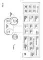
- System 400may include one or more instances of wearable articles 410 configured to transmit and/or receive signals 421 , 422 (handled by stationary module 440 , for example) in a healthcare facility 405 .
- such modulesmay include one or more displays 441 (viewable by a nurse 425 , e.g.), interfaces, and/or storage 442 configured to retain selected components of such signals 421 , 422 .
- a system 500comprising one or more instances of an earpiece 561 , gown 562 , wristband 563 , or other such structures effective for positioning one or more modules configured to communicate in a vicinity 555 of a healthcare recipient 550 who wears the structure(s).
- Other such embodimentsare described herein, optionally configured to communicate with a stationary or other module and/or to include one or more sensors for detecting status indicia relating to healthcare recipient 550 .
- An embodimentprovides a positioning structure 160 configured to be worn by a healthcare recipient 550 , one or more sensors 106 or other detection logic 120 supported by the positioning structure 160 , one or more output devices 126 supported by the positioning structure 160 and configured to transmit at least a signal 170 from the detection logic 120 , and one or more other devices 130 supported by the positioning structure 160 and configured to present at least some health-related information 240 in a vicinity 555 of the healthcare recipient 550 .
- Other such embodimentsare described below with reference to FIGS. 6-26 .
- FIG. 6shown is a system 600 in which one or more technologies may be implemented comprising wearable or other articles 610 operable for handling communications to and/or from one or more networks 690 .
- articlesmay include one or more instances of data 650 ; input devices 660 ; profile detectors 671 , detection modules 672 , or other condition detection logic 675 ; or transmitters 681 or other conduits 685 operable for bearing one or more signals 682 .
- Data 650may include one or more queries 621 , gestures 622 , images 623 , symbols 624 , call signals 625 , authorizations 626 , notifications 627 , or other such input 620 ; local parameters 631 , systemic parameters 632 , or other physiological parameters 635 relating to a healthcare recipient; or environmental parameters 641 or other sensor data 642 as described herein.
- Input device 660may include one or more instances of translators 651 , voice interfaces 652 , recognition logic 653 , touchscreen displays 654 (optionally operable with a stylus 655 , e.g.), cameras 656 , or other sensors 657 , 658 .
- An embodimentprovides a positioning structure configured to be worn by a healthcare recipient 550 , one or more conduits 685 or other receivers supported by a positioning structure (such as an article 610 wearable by a healthcare recipient 550 ) and configured to receive a wireless or other signal 682 , and one or more input devices 660 supported by the positioning structure and configured to transmit at least some physiological parameters 635 or other health-related information in a vicinity 555 of the healthcare recipient responsive to signal 682 (from network 690 , e.g.).
- an earpiece 561 , gown 562 , wristband 563 or other positioning structure for in-patient careexclusively supports institutional broadcasts or other content controlled by and/or provided in a healthcare facility 405 .
- wearable articles 410 or other positioning structuresmay (optionally) include or otherwise interact with sensors or other components effectively permitting use by or other interaction with the healthcare recipient.
- Such structuresmay, for example, support one or more voice interfaces 652 , a stylus 655 , or other input devices 660 configured to permit user input from the healthcare recipient 550 .
- Positioning structure 760may include or otherwise position one or more instances of sensors 705 , global positioning systems 706 , comparators 707 , or other such modules 708 of detection logic 710 .
- sensorsmay include one or more proximity sensors 701 , accelerometers 702 , or other components described, for example, below with reference to FIGS. 14-17 .
- Such a positioning structuremay further include one or more displays 711 , speakers 712 , or other output devices 721 , 722 ; sensors 732 ; or input devices 733 to permit interactions with a healthcare recipient (via user interaction device 730 , e.g.).
- Such positioning structuresmay likewise include one or more output devices 725 operably coupled with one or more antennas or other energy transmission media 790 .
- Such mediamay transmit advice 734 , status updates 735 , research 738 , or other information 740 , 741 , 742 or other notifications 743 ; coordinates 761 , scalar values 762 , 767 , sensor data 764 , or user input 768 as described herein, optionally as signal 770 .
- An embodimentprovides a positioning structure 760 configured to be worn by a healthcare recipient, an accelerometer 702 or other such detection logic 710 operable for detecting movement and supported by the positioning structure 760 , one or more output devices 725 supported by the positioning structure 760 and configured to transmit wireless or other signals 770 from the detection logic 710 , and one or more output devices 721 supported by the positioning structure 760 and configured to present at least some health-related information in a vicinity of the healthcare recipient. This can occur, for example, in a context in which such circuitry implements or otherwise interacts with one or more local modules (of FIGS. 11-17 , e.g.) within, on, or near the healthcare recipient.
- An embodimentprovides a garment or other positioning structure 760 configured to be worn by a healthcare recipient 550 , one or more output devices 721 , 725 supported by the positioning structure 760 and configured to present at least some health-related information in a vicinity of the healthcare recipient 550 ; and one or more output devices 722 , 725 supported by the positioning structure 760 and configured to transmit signal 770 containing one or more coordinates 761 or other scalar values 762 , 767 indicating a (past or current) position of the healthcare recipient 550 .
- output device 725may include one or more light emitting diodes, powered displays, or other device-readable energy transmission media 790 .
- a network 800comprising one or more stationary modules 810 or other facilities for interacting with physicians 821 or other parties 822 or resources 850 via linkages 825 .
- stationary modulesmay include one or more modules 812 of response logic 815 .
- resourcesmay include one or more instructions 831 , position data 832 , or records 841 , 842 comprising profiles 833 as described herein.
- a regional call center or other such servicemay maintain numerous interaction profiles 833 or other configuration data 830 continually in response to telephonic or other incoming requests.
- Healthcare recipients or small healthcare facilitiesmay, for example, use such data and/or devices to facilitate interactions with patient monitoring data aggregation, consultation, research assistance, resource referral, or other such telemedicine and related online services.
- one or more modules 812 of response logic 815may respond to such events or other conditions by transmitting the notification(s) to an interested party 822 and/or other selective destinations identified in record 841 .
- Other such embodimentsare described, for example, below with reference to FIGS. 9-26 .
- a system 900comprising one or more instances of eyewear 951 , sensing units 952 , interface units 953 , 954 , or other such structure(s) effective for positioning one or more modules configured to communicate in a vicinity 955 of a healthcare recipient 950 who wears the structure(s).
- Other such embodimentsare described herein, optionally configured to communicate with a stationary or other module and/or to include one or more sensors for detecting status indicia relating to healthcare recipient 950 .
- An embodimentprovides special-purpose eyewear 951 , one or more sensing units 952 or interface units 953 , 954 , or other such positioning structures configured to be worn by a healthcare recipient 950 ; one or more output devices 361 supported by the positioning structure and configured to transmit at least some positive messages 311 or other health-related data 365 (optionally interspersed with notifications 315 or other information) in a vicinity 955 of the healthcare recipient 950 ; and one or more output devices 361 supported by the positioning structure and configured to transmit a wireless or other signal containing one or more coordinates 761 or other scalar values 762 indicating a (past or current) position of the healthcare recipient 950 .
- a nurse 425 or other party 822can use a stationary module 440 or other linkage 825 to transmit one or more instructions 831 to configure a recipient-specific interaction profile 833 containing one or more records 841 , 842 associating a medical or other condition with one or more notifications 315 , for example, to be delivered via output device 361 and/or in a vicinity 555 , 955 of the healthcare recipient(s) or other subscribers.
- System 1000may be positioned centrally or local to healthcare recipients 1010 , 1020 , for example, and/or configured to invoke one or more interfaces 1030 or other response logic 1035 in response to one or more indications 1011 , 1012 , 1013 , 1014 , 1021 from sensors 1017 , 1026 , 1027 in, on, or near extremities 1028 or other body parts of interest. This can occur, for example, in a context in which hosiery 1018 , clothing, or one or more stationary or other utility devices 1025 within a detection range of sensors 1017 , 1026 , 1027 implements or otherwise interacts with system 1000 .
- such sensorsmay be implanted in a body tissue of interest or in a structure with which healthcare recipients 1010 , 1020 may interact. Alternatively or additionally, some such sensors may be worn as clothing, a support, a patch, a bandage, a watch, or some other article in the healthcare recipients' vicinity.
- Such articlesmay (optionally) include one or more instances of wearable display or other storage or communication media 1040 configured to bear one or more percentages 1043 or other health indications 1041 , 1042 , 1044 such as content 1045 ; information 1046 ; decisions 1047 ; or notifications 1048 containing content 1049 , for example, in flows as described below.
- one or more modules 332 of response logic 335 , 815 , 1035are configured to cause one or more notifications 315 to be routed locally to one or more speakers or other output devices 361 in a vicinity 555 , 955 of a healthcare recipient 550 , 950 .
- such systemsmay include one or more utility devices 1025 , wearable sensors 1017 , 1027 , or other such modules configured to process, present, or otherwise handle raw or other current sensor data as described herein.
- FIG. 11shown is a system 1100 in which one or more technologies may be implemented comprising one or more local modules 1110 operably coupled with one or more interfaces 1180 in a network 1190 .
- Local module 1110may handle or otherwise include one or more decisions 1131 , 1132 of various types 1133 , sensors 1134 , display elements 1136 , or channels 1150 operable for triggering or transmitting one or more notifications 1141 , 1142 such as content 1144 , optionally via one or more radio-frequency or other antennas 1149 .
- Such antennasmay be used in an implanted or other portable article, for example, as described throughout this document.
- such notification logicmay be configured to provide timely information or advice to one or more individuals in a healthcare recipient's vicinity.
- network componentsmay include media configured for display: flat screen displays, image-projecting devices, touch screens, or other such display media.
- An embodimentprovides a local module 1110 or other positioning structure configured to be worn by a healthcare recipient, one or more antennas 1149 or other receivers supported by the positioning structure and configured to receive a wireless or other signal 1170 , and one or more display elements 1136 or other output devices supported by the positioning structure and configured to present one or more options, decisions 1131 , 1132 , or other health-related information responsive to signal 1170 and to one or more status updates (from a sensor 1134 or other input device 660 , e.g.) relating to the healthcare recipient.
- Thiscan occur, for example, in a context in which local module 1110 and/or network 1190 includes one or more components or instances of article 610 .
- such circuitrycan implement or otherwise interact with one or more local modules (of FIGS. 11-17 , e.g.) within, on, or near the healthcare recipient.
- One or more wearable straps or other such local modules 1270may, for example, comprise one or more modules 1241 , 1242 , 1243 of detection logic 1240 ; modules 1251 , 1252 of responsive logic 1250 or other circuitry for generating or using detection results 1255 or other indications 1256 as described below; or interfaces 1260 for interacting with a healthcare recipient or other such user.
- An embodimentprovides a seatbelt comprising one or modules 1242 of detection logic 1240 configured as circuitry for causing one or more evaluations of incoming signals indicating a status of an occupant's seat, back, feet, or other force-bearing body parts that may suffer poor circulation or other such localized health problems for long periods.
- Such embodimentsmay be used, for example, in a context in which an occupant is cognitively or otherwise unable to respond to such problems.
- a worn articlemay include or otherwise support elastic or other tensile elements configured to urge sensors toward a sitting healthcare recipient.
- “health status” indicative datacan reflect a physiological trend or other time-dependent phenomenon indicating some aspect of a healthcare recipient's condition.
- a health status indicative data setcan include portions that have no bearing upon a given healthcare recipient's health.
- distillationscan require authority or substantial expertise (e.g. making a final decision upon a risky procedure or other course of treatment), many other types of distillations can readily be implemented without undue experimentation in light of teachings herein.
- An embodimentprovides a positioning structure or other local module 1270 configured to be worn by a healthcare recipient, one or more receivers or other modules 1252 of responsive logic 1250 supported by the positioning structure and configured to receive an indication 1256 of a medical procedure, regimen, or other option or intention of a caregiver (as a wireless or other signal, e.g.), and one or more interfaces 1260 or other such user interaction devices supported by the positioning structure and configured to present at least some such indications relating to health in a vicinity of the healthcare recipient.
- a positioning structure or other local module 1270configured to be worn by a healthcare recipient
- one or more receivers or other modules 1252 of responsive logic 1250supported by the positioning structure and configured to receive an indication 1256 of a medical procedure, regimen, or other option or intention of a caregiver (as a wireless or other signal, e.g.)
- interfaces 1260 or other such user interaction devicessupported by the positioning structure and configured to present at least some such indications relating to health in a vicinity of the healthcare recipient.
- such detection logicmay be implemented in hosiery, wristbands, bandages, or other such worn articles. Other such embodiments are described, for example, with reference to FIGS. 1-5 . In some variants, such embodiments may incorporate one or more existing technologies like those of the “BT2” wristwatch design, described at www.exmocare.com and in the Information Disclosure Statement filed herewith.
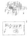
- Adhesive patch 1332holds an array 1325 of sensor elements 1321 , 1322 in close contact with skin 1306 so that attributes of subcutaneous tissues 1305 , vessels 1309 , or blood 1303 or other such materials may be observed.
- an array 1325may implement combinations of two or more types of sensors and/or related logic as exemplified in relation to FIGS. 14-17 below.
- one or more such elements 1321 , 1322may also include a configurable colorant, a light-emitting diode, or other such external feature detectable by a clinician 1310 and/or by a stationary module 1350 or other apparatus that contains a camera 1356 or other optical sensor.
- An embodimentprovides one or more elements 1322 configured as circuitry for deciding whether to transmit one or more blood clot indications (detected with reference, for example, to one or more components sensed within blood 1303 by element 1321 ) and an adhesive patch 1332 comprising one or more tensile elements configured to hold such elements 1321 , 1322 of array 1325 in tight contact with skin 1306 .
- an adhesive patch 1332comprising one or more tensile elements configured to hold such elements 1321 , 1322 of array 1325 in tight contact with skin 1306 .
- Such embodimentsmay be used, for example, in a context in which each contact element 1321 , 1322 comprises a gel-filled capsule or otherwise includes a liquid-containing medium configured to facilitate acoustic energy passing to or from healthcare recipient 1370 .
- system components described hereinmay be configured to include adhesive, fluid, electrically conductive, and/or other special-purpose substances facilitating effective skin contact.
- system components described hereinmay be configured to facilitate positioning one or more sensors in contact with or in close proximity to a healthcare recipient's skin.
- a stationary module 1350may include one or more cameras 656 , 1356 or other components configured to obtain an image of the output device (as a wireless or other signal, e.g.).
- a local module 1420in which one or more sensor technologies may be implemented, such as for monitoring a device or region, or other such tasks as described herein.
- such modulesmay include one or more microwave frequency sensors 1421 , optionally configured to generate an indication of moisture or related symptoms in or on a healthcare recipient's body.
- local module 1420may include one or more fluorescence sensors 1422 , optionally configured to generate an indication of one or more artificial markers in or on specific tissue.
- Such modulesmay likewise include one or more impedance sensors 1423 , optionally configured to generate healthcare recipient respiration rate indications, to detect fractures or other changes in electrode contact surfaces or other such artificial structures, or to detect other such circumstances relating to a healthcare recipient of interest.
- local module 1420may include one or more conductivity sensors 1424 , optionally configured to monitor sweat, apparent urinary incontinence, or other such external circumstances and/or (internally) to monitor blood flow, electrolyte levels, or other such internal conditions.
- Such modulesmay likewise include one or more electric field sensors 1425 in some variants as described herein, optionally comprising (a) an implanted sensor configured to monitor nerve traffic, (b) an implanted or contact sensor configured to transmit electrocardiogram signals, brain activity indications, or other such status information about a healthcare recipient.
- local module 1420may include one or more carbon dioxide sensors 1431 or other respiration sensors 1432 , optionally comprising a sensor implanted adjacent a target site and configured to monitor one or more indications of concentration, for example, to detect apparent occlusions of a blood vessel near the site.
- Such modulesmay likewise include one or more instances of event detection logic 1433 , pathogen detection logic 1434 , or other condition detection logic 1435 such as for comparing raw output from sensors as described herein with prior or other sensor output, with threshold values to determine an apparent occurrence of an event, or with other condition attributes as described herein for triggering notification or therapy. In some embodiments, several or all of such items may be included in a single instance of local module 1420 .
- a local module 1550in which one or more sensor technologies may be implemented, such as for monitoring a device or region, or other such tasks as described herein.
- such modulesmay include one or more accelerometers 1561 , supported in a fixed relation to a target area, optionally configured to generate an indication of the activity, motion, and/or orientation of the healthcare recipient and/or region.
- local module 1550may include one or more radioactivity sensors 1562 , optionally configured internally or externally to generate an indication of one or more artificial markers in or on specific tissue.
- Such modulesmay likewise include one or more radio frequency sensors 1563 , optionally configured to facilitate communication to, from, or between implanted or external devices, and/or to detect lung- or other such organ-status-indicative information in circumstances in which coupling via a continuous conduit may be undesirable.
- local module 1550may contain one or more metabolic sensors 1564 , optionally configured as an implanted device or an external component configured to monitor the healthcare recipient or region (ex situ or otherwise) and to generate an indication of uptake, breakdown, elimination, and/or other such metabolic processes relating, for example, to therapeutic materials as described herein.
- a metabolic sensormay be configured to indicate a generation and/or elimination of other components resulting from the breakdown of therapeutic components, the use or generation of physiological constituents resulting from glucose transforming into carbon dioxide or other such metabolic processes.
- Such modulesmay likewise contain one or more physiological constituent sensors 1565 , optionally comprising an implanted or other sensor configured to generate an indication of physiological constituent levels observed in a healthcare recipient or subject region.
- Thismay include items such as chemical components (e.g. calcium, sodium, cholesterol, pH), proteins and protein complexes (e.g. hemoglobin, insulin, binding proteins, antibodies) and/or structures (e.g. red and/or white blood cells, bacteria, viruses, platelets).
- chemical componentse.g. calcium, sodium, cholesterol, pH
- proteins and protein complexese.g. hemoglobin, insulin, binding proteins, antibodies
- structurese.g. red and/or white blood cells, bacteria, viruses, platelets.
- local module 1550may likewise (optionally) include one or more flow sensors 1571 , which may be configured to generate an indication of fluid flow in or across a region of interest.
- flow sensors 1571may be configured to generate an indication of fluid flow in or across a region of interest.
- local module 1550may include one or more motion sensors 1572 , optionally configured internally, externally, and/or remotely to give an indication of the motion and/or activity of a device or a portion of a healthcare recipient.
- Such modulesmay likewise include one or more emission sensors 1573 , optionally configured to internally or externally give an indication of patient or region status such as using emitted infrared wavelength and intensity levels as an indication of patient or region temperature.
- emission processesmay be used to monitor artificial markers in or on tissue, for example, for monitoring specific tissue features, processes, constituents, and/or pathogens.
- local module 1550may include one or more gas pressure sensors 1574 configured to monitor ambient pressure levels, applied pressure levels (in hyperbaric chambers, continuous positive airway pressure machines, respirators, or other such artificial devices) and/or pressure levels observed in a gas-filled support structure.
- Local module 1550may likewise include one or more position sensors 1581 configured to monitor patient and/or region orientation. Alternatively or additionally, local module 1550 may include one or more fluid pressure sensors 1582 , optionally configured to transmit or otherwise respond to physiological fluid pressure (aneurysm sac pressure or cranial pressure, e.g.) or external fluid pressure (as an indication of delivery amount and/or proper function in a therapeutic delivery system, for example, or in a fluid-filled support structure as described herein).
- physiological fluid pressureaneurysm sac pressure or cranial pressure, e.g.
- external fluid pressureas an indication of delivery amount and/or proper function in a therapeutic delivery system, for example, or in a fluid-filled support structure as described herein).
- Such modulesmay likewise contain one or more fluid volume sensors 1583 , optionally configured to give an indication of fluid volumes within a patient or region such as blood volume in a heart chamber, artery, or lung (as a measure of disease progression or risk, e.g.).
- local module 1550may include one or more force sensors 1584 , optionally configured (a) to generate a pressure reading or other indication of force applied to a region (as a measure of tissue rigidity, e.g.) or (b) to indicate glaucoma, compartmental syndromes, abnormal structures, or other such potential pathologies.
- Such sensorsmay also be used as an indication of the force applied by a patient and/or region on a support structure to monitor patient activity levels and/or to give an indication of susceptibility to force/pressure related injuries such as pressure ulcers.
- Such modulesmay likewise contain one or more microphones or other sonic sensors 1595 , optionally configured to enable communication to, from, and/or between implanted devices, for the recognition of sonic patterns such as heart rate, respiration rates, voice commands and other verbal input (via one or more sonic pattern sensors 1591 , e.g.) or of a healthcare recipient's potential exposure to external stimuli (via one or more sonic volume sensors 1592 , e.g.). In some embodiments, several or all of such items may be included in a single instance of local module 1550 .
- a local module 1610in which one or more sensor technologies may be implemented, such as for monitoring a device or region.
- such modulesmay (optionally) include one or more temperature sensors 1612 , optionally configured to give an indication of ambient thermal conditions around a patient and/or systemic or local thermal conditions of the patient.
- systemic informationmay refer generally to current measurements, body temperature or other such status information, or other data reflecting one or more attributes of a patient as a whole.
- “Local” informationby contrast, may describe measurements, images, or other such data conventionally pertaining to an identifiable portion of a patient's body.
- thermocouple sensors 1631may be implemented using one or more thermocouple sensors 1631 , for example, in implanted and/or direct contact devices. Thermal probes may likewise be implemented as optical sensors that are implanted, direct contact, and/or remotely operable.
- local module 1610may include one or more blood pressure sensors 1613 , optionally configured to give an indication of peripheral and/or systemic blood pressure of a healthcare recipient.
- Such modulesmay be configured to incorporate one or more fluid pressure sensors 1582 or conductivity sensors 1424 in some implanted contexts.
- one or more force sensors 1584 and/or ultrasound sensors 1641(of ultrasound scanner 1640 , e.g.) may be configured in a transdermal mode, for example, to generate information indicative of blood pressure.
- Local module 1610may likewise include one or more near-infrared sensors 1622 and/or infrared sensors 1623 sensors, optionally configured to determine local oxygenation levels or other such chemical and/or material properties of body tissues or fluids as described herein. Such sensors can likewise be configured as transmittance sensors 1621 , for example, receiving radiation that has passed through a patient fingertip or earlobe, or in other such short-path contexts such that the opacity of a tissue region allows for sufficient incident radiation to pass through it to form a usable image. Alternatively or additionally, local module 1610 may comprise one or more reflectance sensors 1611 configured to emit energy into tissue and to capture a portion of the energy reflected.
- local module 1610may contain one or more activity sensors 1632 , weight sensors 1633 and/or tissue pressure sensors 1636 , optionally configured to give an indication of patient activity, motion, or other information indicative of systemic or local physical status.
- Such modulesmay likewise include one or more magnetic field sensors 1647 , optionally configured to allow for the control and/or inhibition of implanted devices transdermally.
- local module 1610may include mass-indicative or other electrochemical sensors 1648 , any of which may (optionally) be configured to give an indication of physiological constituent levels such as by incorporating ion-selective electrodes 1651 (of ion sensor 1650 , e.g.) or other concentration-indicative sensors 1660 for the monitoring of potassium, sodium, calcium, and/or other physiologically relevant components (at pH sensor 1661 or other concentration-indicative sensors 1660 , e.g.).
- electrochemical sensors 1648can be used in a faradaic mode to monitor levels of other relevant physiological components such as blood glucose levels, neurotransmitter release, blood oxygen levels, or other useful components either in an implanted setting and/or a contact setting (in which the sensor is inserted through the skin to the detection site, for example, or the target molecules can be isolated from the healthcare recipient and detected externally.
- Such modulescan also use one or more electrochemical sensors 1648 and/or optical sensors 1625 (including fluorescence sensors 1422 , emission sensors 1573 , near-infrared sensors 1622 , or infrared sensors 1623 ) individually or in combination to provide information for the monitoring of a drug substance administered to the healthcare recipient (such as drug sensor 1662 , e.g.).
- Local module 1610may also implement one or more timestamps 1644 , location coordinates 1645 , or other such indices 1646 relating to measurements or other aspects of healthcare recipient status information. In some embodiments, several or all of such items may be included in a single instance of local module 1610 .
- a local module 1790in which one or more technologies may be implemented, optionally within a sensor, sensor-containing module, or other local instrumentation.
- Any of local modules 1420 , 1550 , 1610may (optionally) include one or more instances of differential or other comparators 1770 configured to process one or more instances of real-time data 1781 , historical data 1782 , force-indicative data 1783 , pathology-indicative data 1784 , measurement data 1785 using one or more standards 1771 , thresholds 1772 , or other input 1773 .
- thresholds 1772configured to implement conditional retention, conditional transmission, or other such selective treatment to pressure-indicative, shear-indicative, strain-indicative, stress-indicative, deformation-indicative, acceleration-indicative, or other such force-indicative data 1783 in light of teachings herein.
- An embodimentprovides an adhesive patch 1332 or other positioning structure 760 configured to be worn by a healthcare recipient 1370 , 2010 ; one or more receiver and/or display elements 1321 supported by the positioning structure and configured to receive a signal 682 ; and one or more receiver and/or display elements 1322 supported by the positioning structure and configured to present or otherwise transmit an alert or other health-related information 740 responsive to signal 682 and to one or more status updates relating to the healthcare recipient.
- Thiscan occur, for example, in a context in which such status updates 735 include physiological parameters 635 , images, or other such indications from sensors on or inside the recipient.
- article 610may include or communicate with one or more implants or adhesive patches 1331 , 1332 implementing one or more local modules 1420 , 1550 , 1610 , 1790 operable to detect physiological phenomena of interest.
- condition detection logic 1435may be configured to detect real-time data 1781 indicating that a healthcare recipient 950 is apparently not exhibiting high enough and/or steady enough concentrations of a nutrient or medication, or other such phenomena. Other such embodiments are described above, for example, with reference to FIGS. 1-9 .
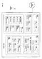
- system 1800that may serve as a context for introducing one or more processes and/or devices described herein, optionally configured to interact with network 1895 .
- systemincludes one or more modules 1872 , 1873 , 1874 , 1877 , 1878 of decision logic 1875 , 1876 ; one or more transmitters 1880 ; and/or one or more parameters 1884 , 1885 of stimula 1881 selected to facilitate one or more sensors 1882 obtaining sensed values 1886 , 1887 or other such test data 1889 about an individual or subpopulation to be monitored.
- System 1800may also include or otherwise interact with one or more instances of structures 1825 configured to obtain data from healthcare recipients 1820 , user interfaces 1852 configured to interact with decision makers or expert resources, or handheld devices 1861 or other such interfaces 1862 for relaying input 1865 to or from other such parties.
- Headgear or other structures 1825 wearable by healthcare recipient 1820may include, for example, one or more instances of identifiers 1823 , status updates, or other data 1821 , 1822 about healthcare recipient 1820 obtained via one or more interfaces 1826 and/or sensors 1827 .
- User interface 1852may likewise present visual or other output 1853 and/or receive keyed or other input 1854 .
- Response logic 1870 as an entitymay receive and/or transmit a variety of interactive data 1855 or other signals 1835 for or from network 1895 , in some contexts, as exemplified below. In various examples below, for example, one or more such patients, caregivers, or others are potential message or other notification recipients. Some such entities have a priori information associating a recipient identifier or other indicator with current signals 1835 or other data as described below.
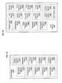
- modules 1872 of decision logic 1875comprising circuitry for transmitting a common graphical image containing information indicating a current local stress in a peripheral part of the healthcare recipient's body with information indicating a prior local stress in the peripheral part of the healthcare recipient's body.
- module 1872invokes transmitter 1880 to cause one or more composite images or other such successive indications relating to a subject's limb or back to output 1853 .
- a local system or mediation module 1910uploads such images or other measurement data to an implementation of response logic 1870 in network 1990 , for example, responsive to a request that remote users may generate after notifications as described herein.
- one or more such usersmay respond by modifying one or more standards 1771 or configurations of buffers, in some variants, so that subsequent sense data may result in other patterns of data capture and/or notification as described herein.
- modules 1873 of decision logic 1875comprising circuitry for relating local circulatory information to one or more of a thigh location, a calf location, or a foot location of a leg of the healthcare recipient. This can occur, for example, in a context in which module 1873 of decision logic 1875 receives signal 1835 or other data causing an activation of one or more sensors identified with or otherwise identifying such a body portion within recipient 1820 . This can occur, for example, in a context in which one or more sensors 1827 are positioned on or near the subject portion). In some contexts, for example, one or more such portions may be selected as a primary sensor location for (local) body part monitoring. Alternatively or additionally, one or more other sensors as described with reference to FIG. 14-17 may be positioned to monitor such subject portions and/or other contemporaneous attributes of the healthcare recipient as described herein.
- modules 1877 of decision logic 1876comprising circuitry for detecting one or more indications of normalcy as a current (thermal, inflammatory, auditory, and/or other physiological) condition in a peripheral part of the healthcare recipient. This can occur, for example, in a context in which module 1877 indicates normalcy in response to receiving a high-enough and/or low-enough numerical value 1887 directly or indirectly from one or more sensors 1827 operable for detecting a temperature at an extremity of recipient 1820 .
- module 1877may employ this information as a factor in deciding whether to transmit a notification to user interface 1852 or to other destinations.
- structure 1825may include one or more instances of response logic or other circuitry operable for responding conditionally to an identifier 1823 of a subject or other determinants in detected data 1822 .
- 6,757,412System and method for helping to determine the condition of tissue”
- U.S. Pat. No. 6,126,614Apparatus and method for analysis of ear, pathologies by detecting fluid in the ear measuring body temperature and/or determining a characteristic of a fluid”
- U.S. Pat. No. 6,023,637Method and apparatus for thermal radiation imaging”
- U.S. Pat. No. 5,999,842Fluorcial thermal imaging apparatus”
- U.S. Pat. No. 5,997,472Endodiagnostic method using differential thermal relaxation and IR imaging”.
- An embodimentprovides headset or other positioning structure 1825 configured to be worn by a healthcare recipient 1820 , one or more interfaces 1826 or other receivers supported by the positioning structure 1825 and configured to receive a wireless or other signal 1835 , and at least one speaker or other output device supported by the positioning structure 1825 and configured to present or otherwise transmit at least a pharmaceutical or other health-related identifier 1823 , a response to a recipient query, or other such health-related or other data 1822 needed by recipient 1820 , provided in the signal 1835 , and/or responsive to data 1821 from one or more sensors 1827 in proximity to the recipient 1820 .
- Other such embodimentsare described above, for example, with reference to FIGS. 1-9 .
- a system 1900comprising a mediation module 1910 , such as may be configured to facilitate data aggregation or other such data-transformative interaction between one or more networks 1990 and a primary or other local system as described herein.
- Mediation module 1910may include one or more recorders 1911 ; ports 1921 , modules 1922 , 1923 or other invocation logic 1920 ; or modules 1932 , 1933 or other processing logic 1930 , such as for applying a threshold 1931 .
- Such componentsmay, for example, trigger a recording or analysis in response to one or more instances of limb pain indications 1944 , cooling indication 1945 , swelling indications 1946 , dispensation indications 1947 , discoloration indications 1948 , symptom indications 1949 , decibel measurements 1951 , 1952 , timing data 1961 , 1962 , 1963 , or a low-enough Reynolds number computation or other laminar-flow-indicative value 1971 , 1972 .
- these or other data typesmay be used as confirmatory measurements 1953 or other data configured for a contingent confirmation of a follow-up evaluation, a diagnosis, a referral, a prognosis, or some other hypothesis of potential therapeutic relevance.
- invocation logic 1920may trigger one or more decisions 1991 , 1992 or other responses from decision logic 1995 , a remote evaluation module 1996 , or other such entities.
- some or all such data 1940may be transmitted to network 1990 , for example, to permit such recording or other functions to be performed remotely.
- modules 1932 of processing logic 1930comprising (software-implemented or other) circuitry for obtaining a turbulence-indicative auditory value as a flow-change-indicative measurement. This can occur, for example, in a context in which module 1932 accepts one or more (past or present) decibel measurements 1951 , 1952 high enough to indicate turbulence in a blood vessel.
- timing data 1961signifying an appearance or disappearance of detectable turbulence in the blood vessel.
- transition-indicative timing datamay signify a growing thrombosis, a thrombosis breakage, a therapeutic success, or other such flow-change-indicative phenomena.
- invocation logic 1920may trigger one or more remote evaluation modules 1996 to evaluate whether such timing data sufficiently coincides with timing data 1962 of a dispensation, timing data 1963 of a pressure-indicative or other confirmatory measurement 1953 , or other such therapeutically relevant and detectable events.
- modules 1922 of invocation logic 1920comprising circuitry for signaling at least a clot-reducing agent in response to an apparent circulatory degradation. This can occur, for example, in a context in which module 1922 receives and relays the decision 1991 to administer one or more therapeutic components to a nurse or other party cable of administering such agents via port 1921 .
- mediation module 1910interacts with a local module as described herein via port 1921 and in which such flow degradation manifests as one or more of a complaint or other severe limb pain indication 1944 , a swelling indication 1946 , a local discoloration indication 1948 , other such detectable phenomena local to a portion of healthcare recipient's body, or as a confirmatory measurement 1953 (in combination with such indications, e.g.).
- another module 1923may signal a caregiver to check one or more potential effects of the clot-reducing or other therapeutic agents or to provide other appropriate follow-up.
- module 1922may invoke recorder 1911 to capture a distillation of one or more dispensation indications 1947 , symptom indications 1949 , and/or related timing data 1963 selectively for future evaluation.
- the one or more positioning modulesmay be configured to receive health-related or other information via a stationary or other mediation module 1910 , for example, in a healthcare facility 405 .
- Such informationmay include limb pain indications 1944 , swelling indications 1946 , confirmatory measurements 1953 , timing data 1961 , circulatory data, decisions 1991 , or other such data 1940 .
- one or more stationary modules 810 , physicians 821 or other parties 822 , decision logic 1995 , or other such resources 850may provide or respond to such symptom indications 1949 or other health indicia.
- Other such embodimentsare described above, for example, with reference to FIGS. 1-9 .
- a system 2000comprising a primary module 2090 configured to accept indications 2011 , 2012 , 2013 , 2014 from one or more auditory or other sensors 2017 in, on or about a healthcare recipient 2010 .
- inputs 2038 , 2039 or other information 2045 as described hereinmay include one or more categories 2031 , responses 2032 , verifications 2033 , distributions 2034 , or other such data 2041 suitable for inclusion, for example, as content 2071 of a notification 2075 .
- one or more modules 2051 , 2052 or other configuration logic 2055may maintain one or more images 2061 , apply one or more thresholds 2062 , or otherwise provide one or more indications 2080 or notification destinations 2085 in response to then-current contents of memory 2065 .
- datacan be “acceptable” to a data analysis module if some or all of the data can be processed by the module with success.
- An indication of acceptable datacan be appropriate in response to detecting an apparent presence or absence of a pattern in the data, for example, or to determining that the data has a file size or header format that is typical for data processed by the analysis module.
- modules 2052 of configuration logic 2055comprising (software-implemented or other) circuitry for including at least some medical history data in the health-related information. This can occur, for example, in a context in which module 2052 includes a category 2031 , response 2032 , verification 2033 , distribution 2034 , or other caregiver input 2038 within or otherwise with notification content 2071 . This can occur, for example, in a context in which various healthcare recipients 2010 , caregivers, or other parties provide such input as described herein and in which these or other inputs 2038 , 2039 may affect what the notification includes and/or whether or where the notification is transmitted.
- module 2052may respond to an indication 2080 of a resource availability change, such as by rerouting, rescheduling, or otherwise reconfiguring a potential or partial notification's content or delivery parameters.
- an indication of a lack of timely inputmay be included in a notification to another caregiver, in some variants.
- modules 2051 of configuration logic 2055comprising circuitry for performing a comparison using an updated normalcy threshold. This can occur, for example, in a context in which module 2051 changes or otherwise updates one or more optical or other normalcy thresholds 2062 . This can occur, for example, in a context in which such comparative information is derived from sensor data described herein, and in which one or more users or devices have indicated an availability to receive such notifications with one or more such parametric updates.
- information from one or more sensors 2017 on or near a healthcare recipient 2010may be used to generate and/or adjust thresholds applied to sensor data 2041 from one or more other sensors extending into, in contact with, or otherwise arranged around the healthcare recipient.
- historic and/or processed information from a remote storage and/or processing devicemay be used to provide and/or adjust thresholds or other filtering information applied to the sensor data 2041 or other types of information 2045 obtained about the subject limb.
- a module 2120 worn by a healthcare recipientmay include one or more receivers 2121 and/or user interaction devices 2122 , one or more sensors 2123 , 2124 operable for transmitting one or more images 2131 , 2132 (depicting zone 2139 , e.g.), counts 2141 , outputs 2137 from sensors, indicators 2143 , thresholds 2145 or other factors 2142 to be applied, or other such determinants 2150 .
- hub 2130may receive (via one or more interfaces 2160 , e.g.) one or more categories 2144 or other such input 2134 from a user or other local entity.
- one or more modules 2171 , 2172 , 2173 , 2174 of notification logic 2175may configure one or more notifications 2168 for local delivery (via interface 2160 , e.g.) and/or delivery to one or more interfaces 2180 or logging modules 2185 of network 2190 .
- module 2172may configure notification 2168 to include a raw sample of slurred speech 2164 provided by a healthcare recipient in response to programmatic queries, for example, or other such content 2165 of an established diagnostic regimen. Such content may be omitted, in some contexts, in response to a determination that such content is normal (not slurred, e.g.) as described herein.
- An embodimentprovides a sensing unit 952 , interface unit 953 , 954 , module 2120 , or other such positioning structure, one or more receivers 2121 , supported by the positioning structure and configured to receive a wireless or other signal (from hub 2130 , e.g.), and one or more user interaction devices 2122 supported by the positioning structure and configured to present at least some health-related content 2165 or other notifications 2168 in a vicinity 955 of the healthcare recipient 950 responsive to signal.
- a sensing unit 952interface unit 953 , 954 , module 2120 , or other such positioning structure
- one or more receivers 2121supported by the positioning structure and configured to receive a wireless or other signal (from hub 2130 , e.g.)
- hub 2130e.g.
- user interaction devices 2122supported by the positioning structure and configured to present at least some health-related content 2165 or other notifications 2168 in a vicinity 955 of the healthcare recipient 950 responsive to signal.
- a system 2200comprising one or more local modules 2231 , 2232 each in a vicinity of one or more body parts 2221 , 2222 of healthcare recipient 2220 .
- such local modules 2232may include one or more sensors, support elements, dispensers, or other such elements 2233 positioned in contact with or otherwise adjacent a body part 2222 of interest.
- detection logic 1240 , 2240may include one or more instances of configuration modules 2242 , control modules 2251 , invocation modules 2267 , notification modules 2268 , or various recognition modules 2281 , 2282 , 2283 configured to process auditory information 2241 or other input data as described herein.
- Such detection logicmay (optionally) include one or more evaluation modules 2252 configured to implement one or more computed results 2261 , comparison results 2262 , user selections, or other such evaluation results 2263 .
- Such resultsmay arise from a recognition of one or more patterns 2271 , 2272 , 2273 , 2274 , 2275 or profiles 2270 (combinations of patterns, e.g.) evident in data 2291 , 2292 , 2293 , 2294 , 2295 , 2296 residing in memory 2298 .
- recognition module 2281may be configured to recognize one or more extended measurement trends or other such pathological patterns 2271 even in data 2293 still in a normal range, in some contexts.
- one or more recognition modules 2282may be configured to detect a shape, color, or other optical pattern 2275 characteristic of a scar, birthmark, or other common and/or unchanging irregularity manifested in data 2296 and not indicative of a circulatory pathology.
- such notification logicmay be configured to facilitate selective notifications according to one or more controllable parameters.
- one or more recognition modules 2281may be configured to recognize one or more extended measurement trends or other such pathological patterns 2271 even in data 2293 still in a normal range, in some contexts.
- one or more recognition modules 2282may be configured to detect a shape, color, or other optical pattern 2275 characteristic of a scar, birthmark, or other common and/or unchanging irregularity manifested in data 2296 and not indicative of a recognized pathology. Other such embodiments are described above, for example, with reference to FIGS. 1-9 .
- modules 1242 of detection logic 1240comprise circuitry for signaling a decision whether to transmit a component of the health-related information partly in response to auditory information from a vicinity of the healthcare recipient. This can occur, for example, in a context in which module 1242 presents or otherwise transmits a notification partly in response to recognition module 2281 indicating one or more comparison results 2262 and partly in response to recognition module 2283 indicating a recognition of one or more phrases or other patterns 2273 , 2274 in speech or other auditory information 2241 from healthcare recipient 2220 .
- abnormal-temperature-indicative data 2291indicates that healthcare recipient 2220 may currently be impaired and in which at least one such result 2262 of comparing abnormal-temperature-indicative data 2291 with historical or other filtering data indicates that a hot zone of peripheral body part 2222 has become measurably hotter and that peripheral body part 2221 has apparently remained in a normal condition.
- normalitymay be inferred from abnormal-temperature-indicative data 2291 not referring to part 2221 and/or not coming from one or more local modules 2231 in a vicinity of part 2221 .
- the decisionmay depend upon one or more other determinants such as (a) whether a current notification 1142 differs from a prior notification 1141 ; (b) whether interface 1180 indicates that one or more recipients are apparently online; (c) whether any new comparison result reflects a new, unrecognized, and/or other urgent situation; or other criteria as described herein.
- a system 2300comprising one or more modules 2301 , 2302 of extraction logic 2310 configured to process one or more samplings 2314 , distillations 2315 , measurements 2316 , 2317 , 2318 , identifiers 2319 , or other such output 2311 , 2312 from sensors or other detection logic described herein.
- a “distillation”can comprise an average, estimate, range, or other computation at least partly distilling a set of data. It can likewise include an indexing, sorting, summarization, distributed sampling, or other process having a purpose or effect of showing some aspect of the data more concisely or effectively than a conventional display of the entire data.
- Selecting a last portion of a data setcan constitute a distillation, for example, in a context in which the data's utility apparently increases.
- Those skilled in the artwill recognize many useful modes of distilling data in light of the state of the art and of teachings herein.
- Such information 2320 , 2330may further include one or more instances of programmatic advice 2332 , ratios 2334 , computations 2336 , or other such components of notifications 2338 .
- at least one distribution module 2350may be configured to use such information to select one or more destinations 2341 , 2342 among a plurality of destinations 2341 , 2342 , 2343 in response to these or other criteria 2364 (defined in one or more subscriber profiles 2361 , e.g.) or to a client list 2367 .
- notification logic 2175 or other responsive logic described hereinmay use one or more such determinants 2368 to select among one or more databases 2381 or other secondary information sources 2380 to draw upon for contextual information to be included in such notifications.
- logic for applying one or more thresholds or other such criteriamay be configured to preserve relevant data selectively, to generate a summary or evaluation, or otherwise to perform suitable data extractions.
- data extraction criteriacan include maxima or other comparison values applied to durations, counts, lengths, widths, frequencies, signal magnitudes or phases, digital values or the like.
- maxima or other comparison valuesapplied to durations, counts, lengths, widths, frequencies, signal magnitudes or phases, digital values or the like.
- Such criteriacan be applied by determining when or how often a definable pattern can be found: a text string, a quantity, a cough-like sound, an arrhythmia, a visible dilation, a failure to respond, a non-change, an allergic response, a symptom relating to an apparent condition of the user, or the like.
- a programmer or record managermay configure one or more modules 2301 of extraction logic 2310 or other response logic 335 to transmit one or more such notifications 315 to healthcare recipients, care providers, and/or other interested parties 822 .
- Such configurationsmay include encoding one or more client lists 2367 and/or criteria 2364 of each subscriber profile 2361 , for example, or other such determinants 2368 .
- one or more such output devicesmay selectively present the health-related information 2320 with one or more computations 2336 of estimated cost, with updates relating to the recipient's vocations or hobbies, and/or with one or more notifications 2338 apparently unrelated to health.
- such notificationsmay be archived and potentially correlated with physiological abnormalities that follow.
- Other such embodimentsare described above, for example, with reference to FIGS. 1-9 .
- a monitoring unit 2400in which one or more technologies may be implemented, comprising one or more instances of detection logic 2450 and/or storage devices 2490 configured for handling one or more signals 2480 .
- signalsare manifested as light energy 2471 and/or sound energy 2472 passing to or from a subject region via one or more wave guides 2475 .
- one or more sensors 2455 or other modules 2451 of detection logic 2450may permit a rate 2457 , decrease 2458 , or other such element 2459 to be detected in response, for example, to real-time data 1781 .
- detection logic 2450may include or otherwise interact with one or more emitters 2461 , 2462 , 2463 as described below.
- modules 2451 of detection logic 2450comprising circuitry for detecting a (thermal or other) normalization rate decrease. This can occur, for example, in a context in which module 2451 detects that region 2521 does not return to a normal parametric range as quickly as it normally should, in response to local aberrations. This can occur, for example, in a context in which module 2501 remains in place long enough to permit module 2451 to establish a normalcy range relating to such (unsigned) rates of normalization for region 2521 , and in which such a rate apparently decreases several times over an interval of a minute, an hour, a day, or more.
- module 2451may effectively characterize one or more rates at which the temperature distribution of the region returns toward an equilibrium status.
- detection logic 2450may include or otherwise operate in conjunction with a (heating and/or cooling) modulation element 2459 (in module 2501 , e.g.) so that an apparent decrease 2458 in a computed normalization rate 2457 may be distinguished from an environmental trend or otherwise confirmed as an apparent symptom of worsening circulation.
- An embodimentprovides a monitoring unit 2400 configured as a positioning structure configured to be worn by a healthcare recipient, a sensor 2455 or other module 2451 of detection logic 2450 supported by the positioning structure; one or more emitters 2461 , 2462 or other output devices supported by the positioning structure and configured to transmit one or more signals from the detection logic 2450 (as light energy 2471 or sound energy 2472 , e.g.); and one or more other emitters 2462 , 2463 comprising output devices supported by the positioning structure and configured to transmit at least some health-related rates 2457 or other such information to a vicinity of the healthcare recipient.
- An embodimentprovides a physiological support 2510 or other positioning structure configured to be worn on at least a limb 2530 of a healthcare recipient, one or more modules 2503 configured as receivers supported by the positioning structure and configured to receive wireless or other signals 2570 , and at least one emitter 2515 (configured as a speaker or other wireless-signal output device, e.g.) supported by the positioning structure and configured to transmit measurements or other health-related information responsive to signal 2570 and to sensor data from one or more sensor-containing modules 2501 , 2502 in proximity to the healthcare recipient.
- sensor data 2635 , 764can originate from the same or other articles worn by the healthcare recipient.
- System 2500comprises an elastic or other physiological support 2510 wrapped around a subject's limb 2530 and holding several modules 2501 , 2502 , 2503 in contact with the subject's skin 2531 , optionally via a liquid-containing contact-enhancement medium. Some of these modules 2501 , 2502 , 2503 may (a) position a sensor at least in a vicinity of the healthcare recipient for a period of more than an hour and/or (b) implement a receiver for receiving signal 2570 as described herein. In some contexts, for example, bandages or other such physiological supports 2610 as described below may implement system 2500 . In some implementations, for example, such articles may safely remain in place for a day or longer.
- any of modules 2501 , 2502 , 2503may implement one or more sensors of local modules 1420 , 1550 , 1610 configured to provide one or more indications of sensor data captured at different times. Such data may indicate, for example, whether one or more regions 2521 , 2522 of limb 2530 exhibits one or more clotting symptoms across a period of several hours, a week, or longer. In some contexts, such data may be obtained (a) without further involvement of a caregiver and/or (b) from about the same position(s) as a prior sensing event. Alternatively or additionally, such modules may include one or more emitters 2515 operable for facilitating a detection of a bone 2533 or other subcutaneous portion 2532 of limb 2530 . Other such embodiments are described above, for example, with reference to FIGS. 1-9 .
- Structure 2610operable in conjunction with system 2600 , in which one or more technologies may be implemented.
- Structure 2610may include one or more items of transportation or other equipment 2615 , beds 2616 , and/or handheld or other portable items 2625 .
- Such itemsmay include hosiery, adhesive patches, or other such articles 2626 ; bandages or other supports 2627 ; or other such structures as described herein comprising one or more elements 2620 configured to provide information to and/or about such healthcare recipients.
- system 2600may comprise decision logic 2655 and/or interfaces 2670 operable for receiving or otherwise handling sensor data 2635 such as measurements 2631 , timing data 2634 , or other data 2632 , 2633 as described herein.
- System 2600may receive such information 2621 , 2622 , 2623 or otherwise interact with such structures 2610 via one or more intermittent or other data paths 2617 , 2618 , 2619 .
- decision logic 2655may use some or all of such temperatures 2651 or other data 2652 as described herein, such as for causing module 2662 or other logic to configure or route notification 2661 or other data 2665 to one or more outputs 2681 , 2682 .
- An embodimentprovides a medical or veterinary system including a garment, portable item 2625 , or other physiological support 2510 configured for bearing and/or surrounding some or all of a healthcare recipient.
- the systemmay include a cast, elastic wrapping, support hose, a sling, or other such structures (wearable by a human or other healthcare recipient, in some cases) for which supporting a subject's body part is not merely an incidental effect.
- Such systemsmay likewise include a monitoring unit 2400 or other device configured for communication, battery recharging, data synchronization, or other such support functions, for example, in a healthcare facility or home.
- the support(s)may contain or otherwise include circuitry for sensing a local temperature or other intensive property of tissue at an extremity or other body part directly.
- such sensing circuitrymay derive such a value, such as by computing a ratio of estimates of two extensive properties of the healthcare recipient's limb.
- a signal-to-noise ratio (SNR) of such sensingmay be increased by subtracting or otherwise mitigating an effect from skin or other external body portions, an effect from bones or other hard structures, an effect from an artificial or (prior) normal condition of the healthcare recipient, or other effects unrelated to the vasculature and/or to any meaningful intensive property trend.
- SNRsignal-to-noise ratio
- a suitable threshold for a first potential trendmay be on the order of 2-20 minutes or hours. Such trends may include indications of rapid local clotting, of a hemodynamic instability, or of other such imminent threats, for example. Alternatively or additionally, a suitable threshold for plaque accumulation or other such (more gradual) trends may be on the order of 1-3 days or months.
- a flow 2700comprising operation 2730 —obtaining information indicating a current thermal condition in a peripheral body part of the healthcare recipient (e.g. decision logic 2655 receiving one or more temperatures 2651 or other such information 2621 , 2622 , 2623 via one or more portable items 2625 or other equipment 2615 within a proximity of the healthcare recipient).
- decision logic 2655receiving one or more temperatures 2651 or other such information 2621 , 2622 , 2623 via one or more portable items 2625 or other equipment 2615 within a proximity of the healthcare recipient.
- Thiscan occur, for example, in a context in which system 2600 implements or otherwise interacts with such structures 2610 , such as by one or more conduits or other signal paths 2617 , 2618 , 2619 .
- decision logic 2655may reside within one or more worn articles 2626 , a bed 2616 , or other equipment 2615 configured to support some or all of a healthcare recipient.
- one or more such structures 2610may comprise or receive data from one or more implanted or other sensors and/or related circuitry as described above with reference to FIGS. 14-17 .
- Such physical componentsmay likewise incorporate or interact one or more instances of interface 2670 operable for interacting with (some) such patients or other parties, such as by performing operation 2790 .
- Operation 2790describes signaling a decision whether to transmit a notification at least partly in response to one or more comparisons between the information indicating the current thermal condition in the peripheral body part of the healthcare recipient and information indicating a prior thermal condition in the peripheral body part of the healthcare recipient (e.g. interface 2670 directing one or more notifications 2661 to one or more outputs 2681 corresponding to recipients who have requested or may otherwise benefit from such timely information).
- interface 2670directing one or more notifications 2661 to one or more outputs 2681 corresponding to recipients who have requested or may otherwise benefit from such timely information.
- Thiscan occur, for example, in a context in which decision logic 2655 has addressed the notifications or otherwise selected the output(s) 2681 according to one or more expert-defined thresholds or other criteria as described herein.
- a recipient or other managing entity associated with output 2682may choose a more extreme temperature or other threshold as a cutoff in response to receiving an excessive number of notifications that are not actionable.
- such an entitymay likewise choose a mode of transmission, an inclusion of data 2665 , or some other aspect of configuring notification 2661 in response to a recipient's indication of availability as described herein.
- Operation 2730obtaining information indicating a current thermal condition in a peripheral body part of a healthcare recipient—may (optionally) include one or more of the following operations: 2835 or 2837 .
- variants of operation 2730may be performed by one or more instances of detection logic 1240 , 2240 or other such data reception or distillation logic as described herein.
- Operation 2790may include one or more of the following operations: 2891 , 2893 , 2896 or 2899 .
- variants of operation 2790may be performed by one or more instances of detection logic 120 , 710 , 1240 ; or other such processing and/or communication components.
- flow 2700may be performed in a context as described above.
- Operation 2835describes determining that the information apparently manifests the current thermal condition in the peripheral body part of the healthcare recipient (e.g. evaluation module 2252 identifying abnormal-temperature-indicative data 2291 received from one or more components of local module 2232 and normal-temperature-indicative data 2292 received from local module 2231 ). This can occur, for example, in a context in which configuration module 2242 and evaluation module 2252 jointly perform operation 2730 ; in which other components of detection logic 2240 perform operation 2790 ; in which evaluation module 2252 implicitly treats such data 2291 - 2296 as “current” and “spatially separated” for diagnostic purposes; in which at least two such local modules 2231 , 2232 each instantiate local module 1610 of FIG.
- evaluation module 2252identifying abnormal-temperature-indicative data 2291 received from one or more components of local module 2232 and normal-temperature-indicative data 2292 received from local module 2231 .
- one or more elements 2233 of such local modules 2231 , 2232may comprise respective instances of temperature sensors 1612 or other sensors as shown in FIG. 16 .
- some or all such data 2291 - 2296may (optionally) include (a) color-indicative or other measurement data 2294 ; (b) timestamps 1644 , coordinates 1645 , anatomical descriptions, shape data, or other such temporal or spatial indices 1646 ; and/or (c) pathology profile data 2295 ; or other such diagnostically useful information.
- Operation 2837describes extracting a portion of detected information as the information indicating the current thermal condition in the peripheral body part of the healthcare recipient (e.g. module 2302 of extraction logic 2310 selectively including one or more measurements 2317 or ratios 2334 or other measurement-based computations 2336 extracted from output 2312 of sensors or other detection circuitry as described herein). This can occur, for example, in a context in which a sampling 2314 , a distillation 2315 , one or more measurements 2316 , 2317 of particular interest, or some other subset of such output 2312 is logged or otherwise retained for comparison and/or included in one or more notifications as described herein.
- such a notificationmay include a blood pressure measurement 2318 , a range or other type identifier 2319 , and/or other such extracted information 2320 .
- such a notificationmay include advice 2332 , a recipient-appropriate translation, or other such categorical information 2330 extracted from a database 2381 or other such secondary information source 2380 using the extracted information 2320 , for example, as a search term.
- Operation 2891describes deciding whether to transmit the notification responsive to whether any of the one or more comparisons indicate an abnormal temperature change in the peripheral body part of the healthcare recipient (e.g. module 1243 of detection logic 1240 sounding an alarm only if comparison result 1255 indicates that any body part of a healthcare recipient 550 , 950 is excessively hot or cold).
- detection logic 1240is wirelessly or otherwise coupled to respective portions of gown 562 ; in which module 1241 and/or responsive logic 1250 perform operation 2730 ; in which detection logic 1240 performs operation 2790 ; in which monitoring apparatus 1260 resides in a vicinity 555 of healthcare recipient 550 and in which a nearby person may be pre-trained and/or contemporaneously guided to provide adequate and timely aid.
- aidmay include talking with or positioning a healthcare recipient; helping a healthcare recipient to administer medications; obtaining a defibrillator, ECG monitor, or other such therapeutic or diagnostic instruments; or contacting a physician or ambulance for more extreme situations.
- one or more modules 1251 of responsive logic 1250may enable such detection logic periodically or otherwise in response to detected events.
- an item of clothing or other wearable articlemay include one or more instances of local module 1610 of FIG. 16 operable for transmitting comparison results, measurement data, or decisions as described herein.
- Operation 2893describes signaling the decision by transmitting the notification to a portable interface (e.g. channel 1150 transmitting one or more notifications 1141 , 1142 as described herein via one or more antennas 1149 to one or more wearable or other portable interfaces 1180 , 2160 , 2180 or other destinations).
- a portable interfacee.g. channel 1150 transmitting one or more notifications 1141 , 1142 as described herein via one or more antennas 1149 to one or more wearable or other portable interfaces 1180 , 2160 , 2180 or other destinations.
- a portable interfacee.g. channel 1150 transmitting one or more notifications 1141 , 1142 as described herein via one or more antennas 1149 to one or more wearable or other portable interfaces 1180 , 2160 , 2180 or other destinations.
- Thiscan occur, for example, in a context in which such a transmission results from one or more hybrid-data decisions 1131 or other thermally-dependent decisions 1132 and in which one or more controllers as described herein include
- Operation 2896describes ranking a higher-priority destination and a lower-priority destination for the notification (e.g. module 2171 ranking one or more nearby interfaces 2160 with a higher-priority category 2144 than that of one or more interfaces 2180 of network 2190 ).
- Thiscan occur, for example, in a context in which a notification 2168 is first routed to a healthcare recipient or other higher-priority destination and in which a related notification is routed to another party a few minutes or hours later in the event that module 2172 does not receive input 2134 from the higher-priority destination.
- such inputmay include an acknowledgment that someone has received the notification.
- any such decisions, notifications, or determinantsmay be logged to other destinations, such as logging module 2185 .
- Operation 2899describes signaling the decision whether to transmit the notification partly in response to auditory information from the healthcare recipient (e.g. local module 1110 updating a party partly in response to recognition module 2281 indicating one or more comparison results 2262 and partly in response to recognition module 2283 indicating a recognition of one or more phrases or other patterns 2273 , 2274 in speech or other auditory information 2241 from healthcare recipient 2220 ).
- local module 1110updating a party partly in response to recognition module 2281 indicating one or more comparison results 2262 and partly in response to recognition module 2283 indicating a recognition of one or more phrases or other patterns 2273 , 2274 in speech or other auditory information 2241 from healthcare recipient 2220 ).
- abnormal-temperature-indicative data 2291indicates that healthcare recipient 2220 may currently be impaired and in which at least one such result 2262 of comparing abnormal-temperature-indicative data 2291 with historical or other filtering data indicates that a hot zone of peripheral body part 2222 has become measurably hotter and that peripheral body part 2221 has apparently remained in a normal condition.
- normalitymay be inferred from abnormal-temperature-indicative data 2291 not referring to part 2221 and/or not coming from one or more local modules 2231 in a vicinity of part 2221 .
- the decisionmay depend upon one or more other determinants such as (a) whether a current notification 1142 differs from a prior notification 1141 ; (b) whether interface 1180 indicates that one or more recipients are apparently online; (c) whether any new comparison result reflects a new, unrecognized, and/or other urgent situation; or other criteria as described herein.
- Operation 2730obtaining information indicating a current thermal condition in a peripheral body part of a healthcare recipient—may (optionally) include one or more of the following operations: 2931 or 2939 .
- variants of operation 2730may be performed by one or more instances of local modules 1420 , 1550 , 1610 , 1790 , 2231 , 2232 or other modules 2120 configured to handle sensor data; decision logic 1875 , 1995 ; or other components configured to handle such status information.
- Operation 2790may include one or more of the following operations: 2992 , 2995 , 2997 or 2998 .
- variants of operation 2790may be performed by one or more instances of distribution logic; notification logic 2175 ; or other such control or communication components.
- flow 2700may be performed in a context as described above.
- Operation 2931describes obtaining an optical image of the peripheral body part of the healthcare recipient of the information indicating the current thermal condition in the peripheral body part of the healthcare recipient (e.g. module 2120 receiving image 2131 from infrared sensor 1623 or image 2132 from another optical sensor 1625 from a position adjacent a patient's body part).
- module 2120receiving image 2131 from infrared sensor 1623 or image 2132 from another optical sensor 1625 from a position adjacent a patient's body part.
- Thiscan occur, for example, in a context in which a patient or caregiver positions a charge-coupled device or similar image capture mechanism in a vicinity of the body part to monitor a growth or other optically detectable phenomenon, optionally in a manner that captures one or more isotherm-indicative shapes.
- a sensor arraycomprising infrared-sensitive elements may be used for implementing such data capture.
- other radiant-energy-sensitive and/or other elements as described hereinmay be used for sensing diagnostically useful information contemporaneously relating to the
- Operation 2939describes detecting that the information indicates normalcy as the current thermal condition in the peripheral body part of the healthcare recipient (e.g. one or more modules 1877 of decision logic 1876 indicating normalcy in response to receiving a high-enough and/or low-enough numerical value 1887 directly or indirectly from one or more sensors 1827 operable for detecting a temperature at an extremity of healthcare recipient 1820 ).
- Thiscan occur, for example, in a context in which healthcare recipient 1820 rests upon or otherwise interacts with structure 1825 , in which decision logic 1876 is capable of detecting and indicating whether value 1887 is too far from a normal temperature, and in which transmitter 1880 is operable for performing operation 2790 .
- module 1877may employ this information as a factor in deciding whether to transmit a notification to user interface 1852 or to other destinations.
- structure 1825may include one or more instances of response logic or other circuitry operable for responding conditionally to an identifier 1823 of a healthcare recipient or other determinants in detected data 1822 .
- 6,757,412System and method for helping to determine the condition of tissue”
- U.S. Pat. No. 6,126,614Apparatus and method for analysis of ear, pathologies by detecting fluid in the ear measuring body temperature and/or determining a characteristic of a fluid”
- U.S. Pat. No. 6,023,637Method and apparatus for thermal radiation imaging”
- U.S. Pat. No. 5,999,842Fluorcial thermal imaging apparatus”
- U.S. Pat. No. 5,997,472Endodiagnostic method using differential thermal relaxation and IR imaging”.
- Operation 2992describes including auditory data with the notification (e.g. one or more modules 2171 - 2174 of notification logic 2175 configuring notification 2168 to include speech 2164 or other audible data with other content 2165 of notification 2168 delivered to one or more interfaces 2160 , 2180 ).
- Thiscan occur, for example, in a context in which notification logic 2175 performs at least operation 2790 and in which one or more users or devices have indicated a telephone, computer speaker, or other interface facility for handling such data.
- output 2137 from a microphone or other sensor 2124may first be detected as speech, a heartbeat or other audible metabolic indicator, or other device-detectable phenomena in a healthcare recipient's vicinity.
- content 2165 provided with a notification 2168may include one or more instances of translated or other programmatic notifications, for example, suitable for remote delivery at a speaker-containing interface 2180 .
- 6,629,937System for processing audio, video and other data for medical diagnosis and other applications”
- U.S. Pat. No. 6,582,379Apparatus and method of measuring the flow of a liquid, in particular urine, from a patient”
- U.S. Pat. No. 6,126,614Apparatus and method for analysis of ear pathologies by detecting fluid in the ear, measuring body temperature and/or determining a characteristic of a fluid”
- U.S. Pat. No. 6,014,626Patient monitoring system including speech recognition capability”.
- Operation 2995describes selecting one or more destinations for the notification (e.g. distribution module 2350 selecting one or more destinations 2341 , 2342 using client list 2367 or other determinants as described herein). This can occur, for example, in a context in which a wearable article implements system 2300 (of FIG. 23 ) and in which one or more preferences of a client system, member, or other interested party are registered for notification via subscriber profile 2361 or other such indication.
- a nursemay associate one or more healthcare recipient identifiers with a wearable article and/or a notification of changes in symptomatic parameters signaled by indication 1256 and may receive a notification 2338 via a wearable or other local module 1270 , in some variants, in response to a detection of one or more symptoms of interest as described herein.
- a clinician 1310 or other interested partymay receive such a notification 2338 selectively, for example via stationary module 1350 .
- such implementationscan facilitate a faster therapeutic response.
- Operation 2997describes including thermal-decrease-size-indicative information with the notification (e.g. module 2662 including a number of degrees or other data 2665 received as information 2622 , 2623 from one or more portable items 2625 indicating how much a healthcare recipient's appendage has apparently cooled).
- the notificatione.g. module 2662 including a number of degrees or other data 2665 received as information 2622 , 2623 from one or more portable items 2625 indicating how much a healthcare recipient's appendage has apparently cooled.
- Thiscan occur in a context in which such cooling results from a wound dressing or other article significantly impairing a healthcare recipient's circulation, for example, or in which such cooling signifies a return to normalcy from an overly-hot condition.
- a notification recipientmay respond with timely advice for treating the healthcare recipient's leg in response to such quantified notification.
- such informationmay warrant a change in how the healthcare recipient is monitored, such as by decreasing vigilance and/or by monitoring systemic, environmental, or
- Operation 2998describes including spatial-size-indicative information with the notification (e.g. module 2174 of notification logic 2175 including one or more of a scaling factor 2142 or other areal indicator 2143 , photographs or other images 2131 , 2132 , a volumetric or shape-descriptive category 2144 , and/or other such information included in or appended to content 2165 of notification 2168 ).
- Thiscan occur, for example, in a context in which interface 2160 performs operation 2730 , in which module 2173 decides whether to transmit the notification, in which notification logic 2175 performs operation 2790 , and in which a healthcare recipient cannot communicate such information and/or otherwise address a pathology.
- module 2173signals in the affirmative if a hot zone 2139 of an image 2132 is larger than threshold 2145 .
- the decisionmay likewise depend upon one or more of an iteration count 2141 or other indicator of duration, user input 2134 , a concentration or other output 2137 from an electrochemical sensor 1648 (of module 2120 , e.g.), and/or other determinants 2150 as described herein.
- Some variantsinclude one or more modules 118 , 331 for recognizing one or more queries 621 , gestures 622 , images 623 , symbols 624 , call signals 625 , authorizations 626 , notifications 627 or other such patterns of user input 620 in data 650 from one or more sensors in a healthcare recipient's vicinity 555 , 955 . This can occur, for example, in a context in which such circuitry implements or otherwise interacts with one or more local modules 1420 , 1550 , 1610 , 1790 within or near the healthcare recipient.
- Some or all of the embodiments described hereinmay generally comprise technologies for handling one or more bioactive agents and/or carriers in releasable module form, via a liquid-bearing conduit, in a mist or other spray form, in a pumped or other pressurized form, or otherwise according to technologies described herein.
- electrical circuitryincludes, but is not limited to, electrical circuitry having at least one discrete electrical circuit, electrical circuitry having at least one integrated circuit, electrical circuitry having at least one application specific integrated circuit, electrical circuitry forming a general purpose computing device configured by a computer program (e.g., a general purpose computer configured by a computer program which at least partially carries out processes and/or devices described herein, or a microprocessor configured by a computer program which at least partially carries out processes and/or devices described herein), electrical circuitry forming a memory device (e.g., forms of random access memory), and/or electrical circuitry forming a communications device (e.g., a modem, communications switch, or optical-electrical equipment).
- a computer programe.g., a general purpose computer configured by a computer program which at least partially carries out processes and/or devices described herein, or a microprocessor configured by a computer program which at least partially carries out processes and/or devices described herein
- electrical circuitry forming a memory device
- Examples of a signal bearing mediuminclude, but are not limited to, the following: a recordable type medium such as a floppy disk, a hard disk drive, a Compact Disc (CD), a Digital Video Disk (DVD), a digital tape, a computer memory, etc.; and a transmission type medium such as a digital and/or an analog communication medium (e.g., a fiber optic cable, a waveguide, a wired communications link, a wireless communication link (e.g., transmitter, receiver, transmission logic, reception logic, etc.), etc.).
- a recordable type mediumsuch as a floppy disk, a hard disk drive, a Compact Disc (CD), a Digital Video Disk (DVD), a digital tape, a computer memory, etc.
- a transmission type mediumsuch as a digital and/or an analog communication medium (e.g., a fiber optic cable, a waveguide, a wired communications link, a wireless communication link (e.g., transmitter, receiver, transmission logic, reception
- any two components so associatedcan also be viewed as being “operably connected”, or “operably coupled,” to each other to achieve the desired functionality, and any two components capable of being so associated can also be viewed as being “operably couplable,” to each other to achieve the desired functionality.
- operably couplableinclude but are not limited to physically mateable and/or physically interacting components, and/or wirelessly interactable, and/or wirelessly interacting components, and/or logically interacting, and/or logically interactable components.
- one or more componentsmay be referred to herein as “configured to,” “configurable to,” “operable/operative to,” “adapted/adaptable,” “able to,” “conformable/conformed to,” etc.
- “configured to”can generally encompass active-state components and/or inactive-state components and/or standby-state components, unless context requires otherwise.
- examples of such other devices and/or processes and/or systemsmight include—as appropriate to context and application—all or part of devices and/or processes and/or systems of (a) an air conveyance (e.g., an airplane, rocket, helicopter, etc.), (b) a ground conveyance (e.g., a car, truck, locomotive, tank, armored personnel carrier, etc.), (c) a building (e.g., a home, warehouse, office, etc.), (d) an appliance (e.g., a refrigerator, a washing machine, a dryer, etc.), (e) a communications system (e.g., a networked system, a telephone system, a Voice over IP system, etc.), (f) a business entity (e.g., an Internet Service Provider (ISP) entity such as Comcast Cable, Qwest, Southwestern Bell, etc.), or (g) a wired/wireless services entity (e.g., Sprint, Cingular, Nexte
- ISPInternet Service Provider
- use of a system or methodmay occur in a territory even if components are located outside the territory.
- use of a distributed computing systemmay occur in a territory even though parts of the system may be located outside of the territory (e.g., relay, server, processor, signal-bearing medium, transmitting computer, receiving computer, etc. located outside the territory).
- a sale of a system or methodmay likewise occur in a territory even if components of the system or method are located and/or used outside the territory. Further, implementation of at least part of a system for performing a method in one territory does not preclude use of the system in another territory.
- a systemcomprising:
- a positioning structureconfigured to be worn by a healthcare recipient
- a first output devicesupported by the positioning structure and configured to transmit at least a signal from the movement detector
- a second output devicesupported by the positioning structure and configured to transmit at least some health-related information in a vicinity of the healthcare recipient.
- a stationary moduleoperable for transmitting another signal to the receiver.
- a cameraconfigured to obtain an image of the second output device.
- circuitryfor causing a notification to be routed to at least one of the first output device or the second output device.
- circuitryfor invoking at least one of the first output device, the second output device, or a third output device selected in response to a configuration parameter.
- circuitryfor including at least some medical history data in the health-related information.
- circuitryfor including at least some real-time data in the health-related information.
- circuitryfor signaling at least a clot-reducing agent in response to an apparent circulatory degradation.
- circuitryfor transmitting data indicating one or more concentrations of a nutrient or medication.
- circuitry for detecting thermal datafor detecting thermal data
- circuitryfor transmitting one or more swelling indications.
- one or more sensorsadjacent a body part of the healthcare recipient.
- a sensorsupported by the positioning structure and configured to generate sensor data
- circuitryfor recognizing a pattern in the sensor data.
- circuitryfor detecting one or more indications of normalcy in the sensor data.
- circuitryfor indicating one or more conditional notifications responsive to the sensor data.
- circuitryfor obtaining a turbulence-indicative auditory value as a flow-change-indicative measurement.
- circuitryfor performing a comparison using an updated normalcy threshold.
- the positioning structuremechanically supporting at least a portion of the circuitry for recognizing the pattern in the sensor data.
- a cuffone or more of a cuff, a sleeve, or a wristband.
- eyewearone or more of eyewear, an earpiece, or a headpiece.
- the positioning structureconfigured to surround a portion of the healthcare recipient.
- At least one of an accelerometer or a proximity sensoris at least one of an accelerometer or a proximity sensor.
- a user interfaceoperable to receive input from the healthcare recipient.
- circuitryfor presenting content provided by a healthcare facility in the healthcare facility.
- circuitryfor transmitting a verification.
- circuitryfor transmitting a resource status indication.
- circuitryfor transmitting other information to one or more other recipients.
- circuitryfor transmitting likelihood-indicative data.
- circuitryfor transmitting one or more limb pain indications.
- circuitryfor obtaining information indicating a current thermal condition in a peripheral body part of the healthcare recipient.
- circuitry for obtaining information indicating a current thermal condition in a peripheral body part of the healthcare recipientcomprises:
- circuitryfor determining that the information apparently manifests the current thermal condition in the peripheral body part of the healthcare recipient.
- circuitry for obtaining information indicating a current thermal condition in a peripheral body part of the healthcare recipientcomprises:
- circuitryfor extracting a portion of detected information as the information indicating the current thermal condition in the peripheral body part of the healthcare recipient.
- circuitry for obtaining information indicating a current thermal condition in a peripheral body part of the healthcare recipientcomprises:
- circuitryfor obtaining an optical image of the peripheral body part of the healthcare recipient of the information indicating the current thermal condition in the peripheral body part of the healthcare recipient.
- circuitry for obtaining information indicating a current thermal condition in a peripheral body part of the healthcare recipientcomprises:
- circuitryfor detecting that the information indicates normalcy as the current thermal condition in the peripheral body part of the healthcare recipient.
- circuitryfor signaling a decision whether to transmit a notification at least partly in response to one or more comparisons between the information indicating the current thermal condition in the peripheral body part of the healthcare recipient and information indicating a prior thermal condition in the peripheral body part of the healthcare recipient.
- circuitry for signaling a decision whether to transmit a notification at least partly in response to one or more comparisons between the information indicating the current thermal condition in the peripheral body part of the healthcare recipient and information indicating a prior thermal condition in the peripheral body part of the healthcare recipientcomprises:
- circuitryfor deciding whether to transmit the notification responsive to whether any of the one or more comparisons indicate an abnormal temperature change in the peripheral body part of the healthcare recipient.
- circuitry for signaling a decision whether to transmit a notification at least partly in response to one or more comparisons between the information indicating the current thermal condition in the peripheral body part of the healthcare recipient and information indicating a prior thermal condition in the peripheral body part of the healthcare recipientcomprises:
- circuitryfor signaling the decision by transmitting the notification to a portable interface.
- circuitry for signaling a decision whether to transmit a notification at least partly in response to one or more comparisons between the information indicating the current thermal condition in the peripheral body part of the healthcare recipient and information indicating a prior thermal condition in the peripheral body part of the healthcare recipientcomprises:
- circuitryfor ranking a higher-priority destination and a lower-priority destination for the notification.
- circuitry for signaling a decision whether to transmit a notification at least partly in response to one or more comparisons between the information indicating the current thermal condition in the peripheral body part of the healthcare recipient and information indicating a prior thermal condition in the peripheral body part of the healthcare recipientcomprises:
- circuitryfor signaling the decision whether to transmit the notification partly in response to auditory information from the healthcare recipient.
- circuitry for signaling a decision whether to transmit a notification at least partly in response to one or more comparisons between the information indicating the current thermal condition in the peripheral body part of the healthcare recipient and information indicating a prior thermal condition in the peripheral body part of the healthcare recipientcomprises:
- circuitryfor including auditory data with the notification.
- circuitry for signaling a decision whether to transmit a notification at least partly in response to one or more comparisons between the information indicating the current thermal condition in the peripheral body part of the healthcare recipient and information indicating a prior thermal condition in the peripheral body part of the healthcare recipientcomprises:
- circuitryfor selecting one or more destinations for the notification.
- circuitry for signaling a decision whether to transmit a notification at least partly in response to one or more comparisons between the information indicating the current thermal condition in the peripheral body part of the healthcare recipient and information indicating a prior thermal condition in the peripheral body part of the healthcare recipientcomprises:
- circuitryfor including thermal-decrease-size-indicative information with the notification.
- circuitry for signaling a decision whether to transmit a notification at least partly in response to one or more comparisons between the information indicating the current thermal condition in the peripheral body part of the healthcare recipient and information indicating a prior thermal condition in the peripheral body part of the healthcare recipientcomprises:
- circuitryfor including spatial-size-indicative information with the notification.
- a systemcomprising:
- a positioning structureconfigured to be worn by a healthcare recipient
- a receiversupported by the positioning structure and configured to receive a wireless signal
- a first output devicesupported by the positioning structure and configured to transmit at least some health-related information responsive to the wireless signal and to a status update relating to the healthcare recipient.
- a stationary moduleoperable for transmitting the wireless signal to the receiver.
- circuitryfor causing a notification to be routed to at least one of the first output device or the second output device.
- circuitryfor invoking at least one of the first output device or a second output device selected in response to a configuration parameter and to the wireless signal.
- circuitryfor including at least some medical history data in the health-related information.
- circuitryfor including at least some real-time data in the health-related information.
- circuitryfor signaling at least a clot-reducing agent in response to an apparent circulatory degradation.
- circuitryfor transmitting data indicating one or more concentrations of a nutrient or medication.
- circuitry for detecting thermal datafor detecting thermal data
- circuitryfor transmitting one or more swelling indications.
- an accelerometersupported by the positioning structure.
- a proximity sensorsupported by the positioning structure.
- one or more sensorsadjacent a body part of the healthcare recipient.
- circuitryfor recognizing a pattern in data from the sensor.
- circuitryfor detecting one or more indications of normalcy in the data from the sensor.
- circuitryfor indicating one or more conditional notifications responsive to the data from the sensor.
- circuitryfor obtaining a turbulence-indicative auditory value as a flow-change-indicative measurement.
- circuitryfor performing a comparison using an updated normalcy threshold.
- the positioning structuremechanically supporting at least a portion of the circuitry for recognizing the pattern in the data from the sensor.
- a cuffone or more of a cuff, a sleeve, or a wristband.
- an earpieceone or more of an earpiece or a headpiece.
- the positioning structureconfigured to surround a portion of the healthcare recipient.
- the output deviceconfigured to receive optical energy as the wireless signal.
- a user interfaceoperable to receive input from the healthcare recipient.
- circuitryfor presenting content provided by a healthcare facility in the healthcare facility.
- circuitryfor transmitting one or more of a verification or a resource status indication.
- circuitryfor transmitting other information to one or more other recipients.
- circuitryfor transmitting the health-related information with one or more computations of cost.
- circuitryfor transmitting likelihood-indicative data.
- circuitryfor transmitting one or more limb pain indications.
- circuitryfor obtaining information indicating a current thermal condition in a peripheral body part of the healthcare recipient.
- circuitry for obtaining information indicating a current thermal condition in a peripheral body part of the healthcare recipientcomprises:
- circuitryfor determining that the information apparently manifests the current thermal condition in the peripheral body part of the healthcare recipient.
- circuitry for obtaining information indicating a current thermal condition in a peripheral body part of the healthcare recipientcomprises:
- circuitryfor extracting a portion of detected information as the information indicating the current thermal condition in the peripheral body part of the healthcare recipient.
- circuitry for obtaining information indicating a current thermal condition in a peripheral body part of the healthcare recipientcomprises:
- circuitryfor obtaining an optical image of the peripheral body part of the healthcare recipient of the information indicating the current thermal condition in the peripheral body part of the healthcare recipient.
- circuitry for obtaining information indicating a current thermal condition in a peripheral body part of the healthcare recipientcomprises:
- circuitryfor detecting that the information indicates normalcy as the current thermal condition in the peripheral body part of the healthcare recipient.
- circuitryfor signaling a decision whether to transmit a notification at least partly in response to one or more comparisons between the information indicating the current thermal condition in the peripheral body part of the healthcare recipient and information indicating a prior thermal condition in the peripheral body part of the healthcare recipient.
- circuitry for signaling a decision whether to transmit a notification at least partly in response to one or more comparisons between the information indicating the current thermal condition in the peripheral body part of the healthcare recipient and information indicating a prior thermal condition in the peripheral body part of the healthcare recipientcomprises:
- circuitryfor deciding whether to transmit the notification responsive to whether any of the one or more comparisons indicate an abnormal temperature change in the peripheral body part of the healthcare recipient.
- circuitry for signaling a decision whether to transmit a notification at least partly in response to one or more comparisons between the information indicating the current thermal condition in the peripheral body part of the healthcare recipient and information indicating a prior thermal condition in the peripheral body part of the healthcare recipientcomprises:
- circuitryfor signaling the decision by transmitting the notification to a portable interface.
- circuitry for signaling a decision whether to transmit a notification at least partly in response to one or more comparisons between the information indicating the current thermal condition in the peripheral body part of the healthcare recipient and information indicating a prior thermal condition in the peripheral body part of the healthcare recipientcomprises:
- circuitryfor ranking a higher-priority destination and a lower-priority destination for the notification.
- circuitry for signaling a decision whether to transmit a notification at least partly in response to one or more comparisons between the information indicating the current thermal condition in the peripheral body part of the healthcare recipient and information indicating a prior thermal condition in the peripheral body part of the healthcare recipientcomprises:
- circuitryfor signaling the decision whether to transmit the notification partly in response to auditory information from the healthcare recipient.
- circuitry for signaling a decision whether to transmit a notification at least partly in response to one or more comparisons between the information indicating the current thermal condition in the peripheral body part of the healthcare recipient and information indicating a prior thermal condition in the peripheral body part of the healthcare recipientcomprises:
- circuitryfor including auditory data with the notification.
- circuitry for signaling a decision whether to transmit a notification at least partly in response to one or more comparisons between the information indicating the current thermal condition in the peripheral body part of the healthcare recipient and information indicating a prior thermal condition in the peripheral body part of the healthcare recipientcomprises:
- circuitryfor selecting one or more destinations for the notification.
- circuitry for signaling a decision whether to transmit a notification at least partly in response to one or more comparisons between the information indicating the current thermal condition in the peripheral body part of the healthcare recipient and information indicating a prior thermal condition in the peripheral body part of the healthcare recipientcomprises:
- circuitryfor including thermal-decrease-size-indicative information with the notification.
- circuitry for signaling a decision whether to transmit a notification at least partly in response to one or more comparisons between the information indicating the current thermal condition in the peripheral body part of the healthcare recipient and information indicating a prior thermal condition in the peripheral body part of the healthcare recipientcomprises:
- circuitryfor including spatial-size-indicative information with the notification.
- a systemcomprising:
- a positioning structureconfigured to be worn by a healthcare recipient
- a receiversupported by the positioning structure and configured to receive a wireless signal
- a first output devicesupported by the positioning structure and configured to present at least some health-related information responsive to the wireless signal and to a status update relating to the healthcare recipient.
- a stationary moduleoperable for transmitting the wireless signal to the receiver.
- circuitryfor causing a notification to be routed to at least one of the first output device or the second output device.
- circuitryfor invoking at least one of the first output device or a second output device selected in response to a configuration parameter and to the wireless signal.
- circuitryfor including at least some medical history data in the health-related information.
- circuitryfor including at least some real-time data in the health-related information.
- circuitryfor signaling at least a clot-reducing agent in response to an apparent circulatory degradation.
- circuitryfor transmitting data indicating one or more concentrations of a nutrient or medication.
- an accelerometersupported by the positioning structure.
- one or more sensorsadjacent a body part of the healthcare recipient.
- circuitryfor recognizing a pattern in data from the sensor.
- circuitryfor detecting one or more indications of normalcy in the data from the sensor.
- circuitryfor indicating one or more conditional notifications responsive to the data from the sensor.
- circuitryfor obtaining a turbulence-indicative auditory value as a flow-change-indicative measurement.
- circuitryfor performing a comparison using an updated normalcy threshold.
- the positioning structuremechanically supporting at least a portion of the circuitry for recognizing the pattern in the data from the sensor.
- eyewearone or more of eyewear, an earpiece, or a headpiece.
- the positioning structureconfigured to surround a portion of the healthcare recipient.
- the output deviceconfigured to receive radio frequency energy as the wireless signal.
- a user interfaceoperable to receive input from the healthcare recipient.
- circuitryfor presenting content provided by a healthcare facility in the healthcare facility.
- circuitryfor presenting one or more of a verification or a resource status indication.
- circuitryfor presenting other information to one or more other recipients.
- circuitryfor presenting the health-related information with one or more computations of cost.
- circuitryfor presenting likelihood-indicative data.
- circuitryfor presenting one or more limb pain indications.
- circuitryfor obtaining information indicating a current thermal condition in a peripheral body part of the healthcare recipient.
- circuitry for obtaining information indicating a current thermal condition in a peripheral body part of the healthcare recipientcomprises:
- circuitryfor determining that the information apparently manifests the current thermal condition in the peripheral body part of the healthcare recipient.
- circuitry for obtaining information indicating a current thermal condition in a peripheral body part of the healthcare recipientcomprises:
- circuitryfor extracting a portion of detected information as the information indicating the current thermal condition in the peripheral body part of the healthcare recipient.
- circuitry for obtaining information indicating a current thermal condition in a peripheral body part of the healthcare recipientcomprises:
- circuitryfor obtaining an optical image of the peripheral body part of the healthcare recipient of the information indicating the current thermal condition in the peripheral body part of the healthcare recipient.
- circuitry for obtaining information indicating a current thermal condition in a peripheral body part of the healthcare recipientcomprises:
- circuitryfor detecting that the information indicates normalcy as the current thermal condition in the peripheral body part of the healthcare recipient.
- circuitryfor signaling a decision whether to transmit a notification at least partly in response to one or more comparisons between the information indicating the current thermal condition in the peripheral body part of the healthcare recipient and information indicating a prior thermal condition in the peripheral body part of the healthcare recipient.
- circuitry for signaling a decision whether to transmit a notification at least partly in response to one or more comparisons between the information indicating the current thermal condition in the peripheral body part of the healthcare recipient and information indicating a prior thermal condition in the peripheral body part of the healthcare recipientcomprises:
- circuitryfor deciding whether to transmit the notification responsive to whether any of the one or more comparisons indicate an abnormal temperature change in the peripheral body part of the healthcare recipient.
- circuitry for signaling a decision whether to transmit a notification at least partly in response to one or more comparisons between the information indicating the current thermal condition in the peripheral body part of the healthcare recipient and information indicating a prior thermal condition in the peripheral body part of the healthcare recipientcomprises:
- circuitryfor signaling the decision by transmitting the notification to a portable interface.
- circuitry for signaling a decision whether to transmit a notification at least partly in response to one or more comparisons between the information indicating the current thermal condition in the peripheral body part of the healthcare recipient and information indicating a prior thermal condition in the peripheral body part of the healthcare recipientcomprises:
- circuitryfor ranking a higher-priority destination and a lower-priority destination for the notification.
- circuitry for signaling a decision whether to transmit a notification at least partly in response to one or more comparisons between the information indicating the current thermal condition in the peripheral body part of the healthcare recipient and information indicating a prior thermal condition in the peripheral body part of the healthcare recipientcomprises:
- circuitryfor signaling the decision whether to transmit the notification partly in response to auditory information from the healthcare recipient.
- circuitry for signaling a decision whether to transmit a notification at least partly in response to one or more comparisons between the information indicating the current thermal condition in the peripheral body part of the healthcare recipient and information indicating a prior thermal condition in the peripheral body part of the healthcare recipientcomprises:
- circuitryfor including auditory data with the notification.
- circuitry for signaling a decision whether to transmit a notification at least partly in response to one or more comparisons between the information indicating the current thermal condition in the peripheral body part of the healthcare recipient and information indicating a prior thermal condition in the peripheral body part of the healthcare recipientcomprises:
- circuitryfor selecting one or more destinations for the notification.
- circuitry for signaling a decision whether to transmit a notification at least partly in response to one or more comparisons between the information indicating the current thermal condition in the peripheral body part of the healthcare recipient and information indicating a prior thermal condition in the peripheral body part of the healthcare recipientcomprises:
- circuitryfor including thermal-decrease-size-indicative information with the notification.
- circuitry for signaling a decision whether to transmit a notification at least partly in response to one or more comparisons between the information indicating the current thermal condition in the peripheral body part of the healthcare recipient and information indicating a prior thermal condition in the peripheral body part of the healthcare recipientcomprises:
- circuitryfor including spatial-size-indicative information with the notification.
- a systemcomprising:
- a positioning structureconfigured to be worn by a healthcare recipient
- a receiversupported by the positioning structure and configured to receive a wireless signal
- a user interaction devicesupported by the positioning structure and configured to present at least some health-related information in a vicinity of the healthcare recipient responsive to the wireless signal.
- a stationary moduleoperable for transmitting the wireless signal to the receiver.
- circuitryfor causing a notification to be routed at least to the user interaction device.
- circuitryfor invoking one or more output devices selected in response to a configuration parameter and to the wireless signal.
- circuitryfor including at least some medical history data in the health-related information.
- circuitryfor including at least some real-time data in the health-related information.
- circuitryfor signaling at least a clot-reducing agent in response to an apparent circulatory degradation.
- circuitryfor transmitting data indicating one or more concentrations of a nutrient or medication.
- circuitry for detecting thermal datafor detecting thermal data
- an accelerometersupported by the positioning structure.
- a proximity sensorsupported by the positioning structure.
- one or more sensorsadjacent a body part of the healthcare recipient.
- circuitryfor recognizing a pattern in data from the sensor.
- circuitryfor detecting one or more indications of normalcy in the data from the sensor.
- circuitryfor indicating one or more conditional notifications responsive to the data from the sensor.
- circuitryfor obtaining a turbulence-indicative auditory value as a flow-change-indicative measurement.
- circuitryfor performing a comparison using an updated normalcy threshold.
- the positioning structuremechanically supporting at least a portion of the circuitry for recognizing the pattern in the data from the sensor.
- a cuffone or more of a cuff, a sleeve, or a wristband.
- eyewearone or more of eyewear, an earpiece, or a headpiece.
- the positioning structureconfigured to surround a portion of the healthcare recipient.
- an optical sensorconfigured to receive optical energy as the wireless signal.
- circuitryfor presenting content provided by a healthcare facility in the healthcare facility.
- circuitryfor presenting one or more of a verification or a resource status indication.
- circuitryfor presenting other information to one or more other recipients.
- circuitryfor presenting the health-related information with one or more computations of cost.
- circuitryfor transmitting likelihood-indicative data.
- circuitryfor transmitting one or more limb pain indications.
- circuitryfor obtaining information indicating a current thermal condition in a peripheral body part of the healthcare recipient.
- circuitry for obtaining information indicating a current thermal condition in a peripheral body part of the healthcare recipientcomprises:
- circuitryfor determining that the information apparently manifests the current thermal condition in the peripheral body part of the healthcare recipient.
- circuitry for obtaining information indicating a current thermal condition in a peripheral body part of the healthcare recipientcomprises:
- circuitryfor extracting a portion of detected information as the information indicating the current thermal condition in the peripheral body part of the healthcare recipient.
- circuitry for obtaining information indicating a current thermal condition in a peripheral body part of the healthcare recipientcomprises:
- circuitryfor obtaining an optical image of the peripheral body part of the healthcare recipient of the information indicating the current thermal condition in the peripheral body part of the healthcare recipient.
- circuitry for obtaining information indicating a current thermal condition in a peripheral body part of the healthcare recipientcomprises:
- circuitryfor detecting that the information indicates normalcy as the current thermal condition in the peripheral body part of the healthcare recipient.
- circuitryfor signaling a decision whether to transmit a notification at least partly in response to one or more comparisons between the information indicating the current thermal condition in the peripheral body part of the healthcare recipient and information indicating a prior thermal condition in the peripheral body part of the healthcare recipient.
- circuitry for signaling a decision whether to transmit a notification at least partly in response to one or more comparisons between the information indicating the current thermal condition in the peripheral body part of the healthcare recipient and information indicating a prior thermal condition in the peripheral body part of the healthcare recipientcomprises:
- circuitryfor deciding whether to transmit the notification responsive to whether any of the one or more comparisons indicate an abnormal temperature change in the peripheral body part of the healthcare recipient.
- circuitry for signaling a decision whether to transmit a notification at least partly in response to one or more comparisons between the information indicating the current thermal condition in the peripheral body part of the healthcare recipient and information indicating a prior thermal condition in the peripheral body part of the healthcare recipientcomprises:
- circuitryfor signaling the decision by transmitting the notification to a portable interface.
- circuitry for signaling a decision whether to transmit a notification at least partly in response to one or more comparisons between the information indicating the current thermal condition in the peripheral body part of the healthcare recipient and information indicating a prior thermal condition in the peripheral body part of the healthcare recipientcomprises:
- circuitryfor ranking a higher-priority destination and a lower-priority destination for the notification.
- circuitry for signaling a decision whether to transmit a notification at least partly in response to one or more comparisons between the information indicating the current thermal condition in the peripheral body part of the healthcare recipient and information indicating a prior thermal condition in the peripheral body part of the healthcare recipientcomprises:
- circuitryfor signaling the decision whether to transmit the notification partly in response to auditory information from the healthcare recipient.
- circuitry for signaling a decision whether to transmit a notification at least partly in response to one or more comparisons between the information indicating the current thermal condition in the peripheral body part of the healthcare recipient and information indicating a prior thermal condition in the peripheral body part of the healthcare recipientcomprises:
- circuitryfor including auditory data with the notification.
- circuitry for signaling a decision whether to transmit a notification at least partly in response to one or more comparisons between the information indicating the current thermal condition in the peripheral body part of the healthcare recipient and information indicating a prior thermal condition in the peripheral body part of the healthcare recipientcomprises:
- circuitryfor selecting one or more destinations for the notification.
- circuitry for signaling a decision whether to transmit a notification at least partly in response to one or more comparisons between the information indicating the current thermal condition in the peripheral body part of the healthcare recipient and information indicating a prior thermal condition in the peripheral body part of the healthcare recipientcomprises:
- circuitryfor including thermal-decrease-size-indicative information with the notification.
- circuitry for signaling a decision whether to transmit a notification at least partly in response to one or more comparisons between the information indicating the current thermal condition in the peripheral body part of the healthcare recipient and information indicating a prior thermal condition in the peripheral body part of the healthcare recipientcomprises:
- circuitryfor including spatial-size-indicative information with the notification.
- a systemcomprising:
- a positioning structureconfigured to be worn by a healthcare recipient
- a first output devicesupported by the positioning structure and configured to transmit at least some health-related information in a vicinity of the healthcare recipient
- a second output devicesupported by the positioning structure and configured to transmit a wireless signal containing one or more scalar values indicating a position of the healthcare recipient.
- a stationary moduleoperable for transmitting another signal to the receiver.
- circuitryfor causing a notification to be routed to at least one of the first output device or the second output device.
- circuitryfor invoking at least one of the first output device, the second output device, or a third output device selected in response to a configuration parameter.
- circuitryfor including at least some medical history data in the health-related information.
- circuitryfor including at least some real-time data in the health-related information.
- circuitryfor signaling at least a clot-reducing agent in response to an apparent circulatory degradation.
- circuitryfor transmitting data indicating one or more concentrations of a nutrient or medication.
- circuitry for detecting thermal datafor detecting thermal data
- circuitryfor transmitting one or more swelling indications.
- one or more sensorsadjacent a body part of the healthcare recipient.
- a sensorsupported by the positioning structure and configured to generate sensor data
- circuitryfor recognizing a pattern in the sensor data.
- circuitryfor detecting one or more indications of normalcy in the sensor data.
- circuitryfor indicating one or more conditional notifications responsive to the sensor data.
- circuitryfor obtaining a turbulence-indicative auditory value as a flow-change-indicative measurement.
- circuitryfor performing a comparison using an updated normalcy threshold.
- the positioning structuremechanically supporting at least a portion of the circuitry for recognizing the pattern in the sensor data.
- a cuffone or more of a cuff, a sleeve, or a wristband.
- eyewearone or more of eyewear, an earpiece, or a headpiece.
- the positioning structureconfigured to surround a portion of the healthcare recipient.
- a user interfaceoperable to receive input from the healthcare recipient.
- circuitryfor presenting content provided by a healthcare facility in the healthcare facility.
- circuitryfor transmitting one or more of a verification or a resource status indication.
- circuitryfor presenting other information to one or more other recipients.
- circuitryfor transmitting the health-related information with one or more computations of cost.
- circuitryfor transmitting likelihood-indicative data.
- circuitryfor obtaining information indicating a current thermal condition in a peripheral body part of the healthcare recipient.
- circuitry for obtaining information indicating a current thermal condition in a peripheral body part of the healthcare recipientcomprises:
- circuitryfor determining that the information apparently manifests the current thermal condition in the peripheral body part of the healthcare recipient.
- circuitry for obtaining information indicating a current thermal condition in a peripheral body part of the healthcare recipientcomprises:
- circuitryfor extracting a portion of detected information as the information indicating the current thermal condition in the peripheral body part of the healthcare recipient.
- circuitry for obtaining information indicating a current thermal condition in a peripheral body part of the healthcare recipientcomprises:
- circuitryfor obtaining an optical image of the peripheral body part of the healthcare recipient of the information indicating the current thermal condition in the peripheral body part of the healthcare recipient.
- circuitry for obtaining information indicating a current thermal condition in a peripheral body part of the healthcare recipientcomprises:
- circuitryfor detecting that the information indicates normalcy as the current thermal condition in the peripheral body part of the healthcare recipient.
- circuitryfor signaling a decision whether to transmit a notification at least partly in response to one or more comparisons between the information indicating the current thermal condition in the peripheral body part of the healthcare recipient and information indicating a prior thermal condition in the peripheral body part of the healthcare recipient.
- circuitry for signaling a decision whether to transmit a notification at least partly in response to one or more comparisons between the information indicating the current thermal condition in the peripheral body part of the healthcare recipient and information indicating a prior thermal condition in the peripheral body part of the healthcare recipientcomprises:
- circuitryfor deciding whether to transmit the notification responsive to whether any of the one or more comparisons indicate an abnormal temperature change in the peripheral body part of the healthcare recipient.
- circuitry for signaling a decision whether to transmit a notification at least partly in response to one or more comparisons between the information indicating the current thermal condition in the peripheral body part of the healthcare recipient and information indicating a prior thermal condition in the peripheral body part of the healthcare recipientcomprises:
- circuitryfor signaling the decision by transmitting the notification to a portable interface.
- circuitry for signaling a decision whether to transmit a notification at least partly in response to one or more comparisons between the information indicating the current thermal condition in the peripheral body part of the healthcare recipient and information indicating a prior thermal condition in the peripheral body part of the healthcare recipientcomprises:
- circuitryfor ranking a higher-priority destination and a lower-priority destination for the notification.
- circuitry for signaling a decision whether to transmit a notification at least partly in response to one or more comparisons between the information indicating the current thermal condition in the peripheral body part of the healthcare recipient and information indicating a prior thermal condition in the peripheral body part of the healthcare recipientcomprises:
- circuitryfor signaling the decision whether to transmit the notification partly in response to auditory information from the healthcare recipient.
- circuitry for signaling a decision whether to transmit a notification at least partly in response to one or more comparisons between the information indicating the current thermal condition in the peripheral body part of the healthcare recipient and information indicating a prior thermal condition in the peripheral body part of the healthcare recipientcomprises:
- circuitryfor including auditory data with the notification.
- circuitry for signaling a decision whether to transmit a notification at least partly in response to one or more comparisons between the information indicating the current thermal condition in the peripheral body part of the healthcare recipient and information indicating a prior thermal condition in the peripheral body part of the healthcare recipientcomprises:
- circuitryfor selecting one or more destinations for the notification.
- circuitry for signaling a decision whether to transmit a notification at least partly in response to one or more comparisons between the information indicating the current thermal condition in the peripheral body part of the healthcare recipient and information indicating a prior thermal condition in the peripheral body part of the healthcare recipientcomprises:
- circuitryfor including thermal-decrease-size-indicative information with the notification.
- circuitry for signaling a decision whether to transmit a notification at least partly in response to one or more comparisons between the information indicating the current thermal condition in the peripheral body part of the healthcare recipient and information indicating a prior thermal condition in the peripheral body part of the healthcare recipientcomprises:
- circuitryfor including spatial-size-indicative information with the notification.
Landscapes
- Health & Medical Sciences (AREA)
- Life Sciences & Earth Sciences (AREA)
- Engineering & Computer Science (AREA)
- General Health & Medical Sciences (AREA)
- Veterinary Medicine (AREA)
- Biophysics (AREA)
- Biomedical Technology (AREA)
- Heart & Thoracic Surgery (AREA)
- Medical Informatics (AREA)
- Molecular Biology (AREA)
- Surgery (AREA)
- Animal Behavior & Ethology (AREA)
- Physics & Mathematics (AREA)
- Public Health (AREA)
- Pathology (AREA)
- Physiology (AREA)
- Vascular Medicine (AREA)
- Pulmonology (AREA)
- Cardiology (AREA)
- Radar, Positioning & Navigation (AREA)
- Dentistry (AREA)
- Oral & Maxillofacial Surgery (AREA)
- Immunology (AREA)
- Urology & Nephrology (AREA)
- Measuring And Recording Apparatus For Diagnosis (AREA)
Abstract
Description
Claims (41)
Priority Applications (1)
| Application Number | Priority Date | Filing Date | Title |
|---|---|---|---|
| US12/231,061US8094009B2 (en) | 2008-08-27 | 2008-08-27 | Health-related signaling via wearable items |
Applications Claiming Priority (1)
| Application Number | Priority Date | Filing Date | Title |
|---|---|---|---|
| US12/231,061US8094009B2 (en) | 2008-08-27 | 2008-08-27 | Health-related signaling via wearable items |
Publications (2)
| Publication Number | Publication Date |
|---|---|
| US20100052898A1 US20100052898A1 (en) | 2010-03-04 |
| US8094009B2true US8094009B2 (en) | 2012-01-10 |
Family
ID=41724505
Family Applications (1)
| Application Number | Title | Priority Date | Filing Date |
|---|---|---|---|
| US12/231,061Active2030-08-23US8094009B2 (en) | 2008-08-27 | 2008-08-27 | Health-related signaling via wearable items |
Country Status (1)
| Country | Link |
|---|---|
| US (1) | US8094009B2 (en) |
Cited By (166)
| Publication number | Priority date | Publication date | Assignee | Title |
|---|---|---|---|---|
| US20050182306A1 (en)* | 2004-02-17 | 2005-08-18 | Therasense, Inc. | Method and system for providing data communication in continuous glucose monitoring and management system |
| US20080256048A1 (en)* | 2007-04-14 | 2008-10-16 | Abbott Diabetes Care, Inc. | Method and apparatus for providing data processing and control in medical communication system |
| US20080255434A1 (en)* | 2007-04-14 | 2008-10-16 | Abbott Diabetes Care, Inc. | Method and apparatus for providing data processing and control in medical communication system |
| US20080281179A1 (en)* | 2007-05-08 | 2008-11-13 | Abbott Diabetes Care, Inc. | Analyte monitoring system and methods |
| US20080278332A1 (en)* | 2007-05-08 | 2008-11-13 | Abbott Diabetes Care, Inc. | Analyte monitoring system and methods |
| US20080286316A1 (en)* | 2007-05-18 | 2008-11-20 | Heidi Kay | Lipid raft, caveolin protein, and caveolar function modulation compounds and associated synthetic and therapeutic methods |
| US20080287762A1 (en)* | 2007-05-14 | 2008-11-20 | Abbott Diabetes Care, Inc. | Method and apparatus for providing data processing and control in a medical communication system |
| US20080287761A1 (en)* | 2007-05-14 | 2008-11-20 | Abbott Diabetes Care, Inc. | Method and apparatus for providing data processing and control in a medical communication system |
| US20080288204A1 (en)* | 2007-04-14 | 2008-11-20 | Abbott Diabetes Care, Inc. | Method and apparatus for providing data processing and control in medical communication system |
| US20080312845A1 (en)* | 2007-05-14 | 2008-12-18 | Abbott Diabetes Care, Inc. | Method and apparatus for providing data processing and control in a medical communication system |
| US20080319296A1 (en)* | 2007-06-21 | 2008-12-25 | Abbott Diabetes Care, Inc. | Health monitor |
| US20080319295A1 (en)* | 2007-06-21 | 2008-12-25 | Abbott Diabetes Care, Inc. | Health management devices and methods |
| US20080319294A1 (en)* | 2007-06-21 | 2008-12-25 | Abbott Diabetes Care, Inc. | Health management devices and methods |
| US20090036760A1 (en)* | 2007-07-31 | 2009-02-05 | Abbott Diabetes Care, Inc. | Method and apparatus for providing data processing and control in a medical communication system |
| US20090105571A1 (en)* | 2006-06-30 | 2009-04-23 | Abbott Diabetes Care, Inc. | Method and System for Providing Data Communication in Data Management Systems |
| US20100052915A1 (en)* | 2008-08-27 | 2010-03-04 | Searete Llc, A Limited Liability Corporation Of The State Of Delaware | Health-related signaling via wearable items |
| US20100082266A1 (en)* | 2003-04-04 | 2010-04-01 | Abbott Diabetes Care Inc. | Method and System for Transferring Analyte Test Data |
| US20100171610A1 (en)* | 2003-04-28 | 2010-07-08 | Abbott Diabetes Care Inc. | Method and Apparatus for Providing Peak Detection Circuitry for Data Communication Systems |
| US20100198034A1 (en)* | 2009-02-03 | 2010-08-05 | Abbott Diabetes Care Inc. | Compact On-Body Physiological Monitoring Devices and Methods Thereof |
| US20100235439A1 (en)* | 2003-07-15 | 2010-09-16 | Abbott Diabetes Care Inc. | Glucose Measuring Device Integrated Into A Holster For A Personal Area Network Device |
| US20100274108A1 (en)* | 2005-09-30 | 2010-10-28 | Abbott Diabetes Care Inc. | Method and Apparatus for Providing Rechargeable Power in Data Monitoring and Management Systems |
| US20110044333A1 (en)* | 2008-05-30 | 2011-02-24 | Abbott Diabetes Care Inc. | Close Proximity Communication Device and Methods |
| US20110054282A1 (en)* | 2009-08-31 | 2011-03-03 | Abbott Diabetes Care Inc. | Analyte Monitoring System and Methods for Managing Power and Noise |
| US20110166940A1 (en)* | 2010-01-05 | 2011-07-07 | Searete Llc | Micro-impulse radar detection of a human demographic and delivery of targeted media content |
| US20110166937A1 (en)* | 2010-01-05 | 2011-07-07 | Searete Llc | Media output with micro-impulse radar feedback of physiological response |
| US20110184268A1 (en)* | 2010-01-22 | 2011-07-28 | Abbott Diabetes Care Inc. | Method, Device and System for Providing Analyte Sensor Calibration |
| US20110213225A1 (en)* | 2009-08-31 | 2011-09-01 | Abbott Diabetes Care Inc. | Medical devices and methods |
| US20110224525A1 (en)* | 2005-10-31 | 2011-09-15 | Abbott Diabetes Care Inc. | Method and Apparatus for Providing Data Communication in Data Monitoring and Management Systems |
| US20120116202A1 (en)* | 2010-01-05 | 2012-05-10 | Searete Llc | Surveillance of stress conditions of persons using micro-impulse radar |
| US8444560B2 (en) | 2007-05-14 | 2013-05-21 | Abbott Diabetes Care Inc. | Method and apparatus for providing data processing and control in a medical communication system |
| US8456301B2 (en) | 2007-05-08 | 2013-06-04 | Abbott Diabetes Care Inc. | Analyte monitoring system and methods |
| US8461985B2 (en) | 2007-05-08 | 2013-06-11 | Abbott Diabetes Care Inc. | Analyte monitoring system and methods |
| US8471714B2 (en) | 2005-05-17 | 2013-06-25 | Abbott Diabetes Care Inc. | Method and system for providing data management in data monitoring system |
| US8542122B2 (en) | 2005-02-08 | 2013-09-24 | Abbott Diabetes Care Inc. | Glucose measurement device and methods using RFID |
| US8543183B2 (en) | 2006-03-31 | 2013-09-24 | Abbott Diabetes Care Inc. | Analyte monitoring and management system and methods therefor |
| US8571808B2 (en) | 2007-05-14 | 2013-10-29 | Abbott Diabetes Care Inc. | Method and apparatus for providing data processing and control in a medical communication system |
| US8593287B2 (en) | 2007-05-08 | 2013-11-26 | Abbott Diabetes Care Inc. | Analyte monitoring system and methods |
| US8593109B2 (en) | 2006-03-31 | 2013-11-26 | Abbott Diabetes Care Inc. | Method and system for powering an electronic device |
| US8612163B2 (en) | 2007-05-14 | 2013-12-17 | Abbott Diabetes Care Inc. | Method and apparatus for providing data processing and control in a medical communication system |
| US8635046B2 (en) | 2010-06-23 | 2014-01-21 | Abbott Diabetes Care Inc. | Method and system for evaluating analyte sensor response characteristics |
| US8682615B2 (en) | 2007-05-14 | 2014-03-25 | Abbott Diabetes Care Inc. | Method and apparatus for providing data processing and control in a medical communication system |
| US8710993B2 (en) | 2011-11-23 | 2014-04-29 | Abbott Diabetes Care Inc. | Mitigating single point failure of devices in an analyte monitoring system and methods thereof |
| US20140207444A1 (en)* | 2011-06-15 | 2014-07-24 | Arie Heiman | System, device and method for detecting speech |
| US8834366B2 (en) | 2007-07-31 | 2014-09-16 | Abbott Diabetes Care Inc. | Method and apparatus for providing analyte sensor calibration |
| US8926561B2 (en) | 2009-07-30 | 2015-01-06 | Tandem Diabetes Care, Inc. | Infusion pump system with disposable cartridge having pressure venting and pressure feedback |
| US8965288B2 (en) | 2012-12-31 | 2015-02-24 | Elwha Llc | Cost-effective mobile connectivity protocols |
| US8986253B2 (en) | 2008-01-25 | 2015-03-24 | Tandem Diabetes Care, Inc. | Two chamber pumps and related methods |
| US9019149B2 (en) | 2010-01-05 | 2015-04-28 | The Invention Science Fund I, Llc | Method and apparatus for measuring the motion of a person |
| US9024814B2 (en) | 2010-01-05 | 2015-05-05 | The Invention Science Fund I, Llc | Tracking identities of persons using micro-impulse radar |
| US9044543B2 (en) | 2012-07-17 | 2015-06-02 | Elwha Llc | Unmanned device utilization methods and systems |
| US9061102B2 (en) | 2012-07-17 | 2015-06-23 | Elwha Llc | Unmanned device interaction methods and systems |
| US9069067B2 (en) | 2010-09-17 | 2015-06-30 | The Invention Science Fund I, Llc | Control of an electronic apparatus using micro-impulse radar |
| US9069536B2 (en) | 2011-10-31 | 2015-06-30 | Abbott Diabetes Care Inc. | Electronic devices having integrated reset systems and methods thereof |
| US9088452B2 (en) | 2009-04-29 | 2015-07-21 | Abbott Diabetes Care Inc. | Method and system for providing data communication in continuous glucose monitoring and management system |
| US9095290B2 (en) | 2007-03-01 | 2015-08-04 | Abbott Diabetes Care Inc. | Method and apparatus for providing rolling data in communication systems |
| US9125548B2 (en) | 2007-05-14 | 2015-09-08 | Abbott Diabetes Care Inc. | Method and apparatus for providing data processing and control in a medical communication system |
| US9180243B2 (en) | 2013-03-15 | 2015-11-10 | Tandem Diabetes Care, Inc. | Detection of infusion pump conditions |
| US9226701B2 (en) | 2009-04-28 | 2016-01-05 | Abbott Diabetes Care Inc. | Error detection in critical repeating data in a wireless sensor system |
| US9317656B2 (en) | 2011-11-23 | 2016-04-19 | Abbott Diabetes Care Inc. | Compatibility mechanisms for devices in a continuous analyte monitoring system and methods thereof |
| US9335910B2 (en) | 2012-04-23 | 2016-05-10 | Tandem Diabetes Care, Inc. | System and method for reduction of inadvertent activation of medical device during manipulation |
| WO2016071754A3 (en)* | 2014-11-03 | 2016-06-30 | Physical Enterprises, Inc. | Systems and methods for optical isolation in measuring physiological parameters |
| US9451394B2 (en) | 2012-12-31 | 2016-09-20 | Elwha Llc | Cost-effective mobile connectivity protocols |
| US9474475B1 (en) | 2013-03-15 | 2016-10-25 | Abbott Diabetes Care Inc. | Multi-rate analyte sensor data collection with sample rate configurable signal processing |
| US9526437B2 (en) | 2012-11-21 | 2016-12-27 | i4c Innovations Inc. | Animal health and wellness monitoring using UWB radar |
| US9532737B2 (en) | 2011-02-28 | 2017-01-03 | Abbott Diabetes Care Inc. | Devices, systems, and methods associated with analyte monitoring devices and devices incorporating the same |
| US9555186B2 (en) | 2012-06-05 | 2017-01-31 | Tandem Diabetes Care, Inc. | Infusion pump system with disposable cartridge having pressure venting and pressure feedback |
| US9574914B2 (en) | 2007-05-08 | 2017-02-21 | Abbott Diabetes Care Inc. | Method and device for determining elapsed sensor life |
| US9596584B2 (en) | 2013-03-15 | 2017-03-14 | Elwha Llc | Protocols for facilitating broader access in wireless communications by conditionally authorizing a charge to an account of a third party |
| US9622691B2 (en) | 2011-10-31 | 2017-04-18 | Abbott Diabetes Care Inc. | Model based variable risk false glucose threshold alarm prevention mechanism |
| US9635605B2 (en) | 2013-03-15 | 2017-04-25 | Elwha Llc | Protocols for facilitating broader access in wireless communications |
| US9662056B2 (en) | 2008-09-30 | 2017-05-30 | Abbott Diabetes Care Inc. | Optimizing analyte sensor calibration |
| US9693214B2 (en) | 2013-03-15 | 2017-06-27 | Elwha Llc | Protocols for facilitating broader access in wireless communications |
| US9706060B2 (en) | 2013-03-15 | 2017-07-11 | Elwha Llc | Protocols for facilitating broader access in wireless communications |
| US9706382B2 (en) | 2013-03-15 | 2017-07-11 | Elwha Llc | Protocols for allocating communication services cost in wireless communications |
| US9713013B2 (en) | 2013-03-15 | 2017-07-18 | Elwha Llc | Protocols for providing wireless communications connectivity maps |
| US9715327B2 (en) | 2012-06-07 | 2017-07-25 | Tandem Diabetes Care, Inc. | Preventing inadvertent changes in ambulatory medical devices |
| US9750444B2 (en) | 2009-09-30 | 2017-09-05 | Abbott Diabetes Care Inc. | Interconnect for on-body analyte monitoring device |
| US9779611B1 (en)* | 2015-05-18 | 2017-10-03 | HCA Holdings, Inc. | Contextual assessment of current conditions |
| US9781554B2 (en) | 2013-03-15 | 2017-10-03 | Elwha Llc | Protocols for facilitating third party authorization for a rooted communication device in wireless communications |
| US9781664B2 (en) | 2012-12-31 | 2017-10-03 | Elwha Llc | Cost-effective mobile connectivity protocols |
| US9807582B2 (en) | 2013-03-15 | 2017-10-31 | Elwha Llc | Protocols for facilitating broader access in wireless communications |
| US9813887B2 (en) | 2013-03-15 | 2017-11-07 | Elwha Llc | Protocols for facilitating broader access in wireless communications responsive to charge authorization statuses |
| US20170337350A1 (en)* | 2014-12-30 | 2017-11-23 | Samsung Electronics Co., Ltd. | User terminal apparatus and method for driving user terminal apparatus |
| US9832628B2 (en) | 2012-12-31 | 2017-11-28 | Elwha, Llc | Cost-effective mobile connectivity protocols |
| US9843917B2 (en) | 2013-03-15 | 2017-12-12 | Elwha, Llc | Protocols for facilitating charge-authorized connectivity in wireless communications |
| US9866706B2 (en) | 2013-03-15 | 2018-01-09 | Elwha Llc | Protocols for facilitating broader access in wireless communications |
| US9876762B2 (en) | 2012-12-31 | 2018-01-23 | Elwha Llc | Cost-effective mobile connectivity protocols |
| US9907492B2 (en) | 2012-09-26 | 2018-03-06 | Abbott Diabetes Care Inc. | Method and apparatus for improving lag correction during in vivo measurement of analyte concentration with analyte concentration variability and range data |
| US9913600B2 (en) | 2007-06-29 | 2018-03-13 | Abbott Diabetes Care Inc. | Analyte monitoring and management device and method to analyze the frequency of user interaction with the device |
| US9962091B2 (en) | 2002-12-31 | 2018-05-08 | Abbott Diabetes Care Inc. | Continuous glucose monitoring system and methods of use |
| US9962486B2 (en) | 2013-03-14 | 2018-05-08 | Tandem Diabetes Care, Inc. | System and method for detecting occlusions in an infusion pump |
| US9968306B2 (en) | 2012-09-17 | 2018-05-15 | Abbott Diabetes Care Inc. | Methods and apparatuses for providing adverse condition notification with enhanced wireless communication range in analyte monitoring systems |
| US9980114B2 (en) | 2013-03-15 | 2018-05-22 | Elwha Llc | Systems and methods for communication management |
| US9980669B2 (en) | 2011-11-07 | 2018-05-29 | Abbott Diabetes Care Inc. | Analyte monitoring device and methods |
| US10002233B2 (en) | 2007-05-14 | 2018-06-19 | Abbott Diabetes Care Inc. | Method and apparatus for providing data processing and control in a medical communication system |
| US10022499B2 (en) | 2007-02-15 | 2018-07-17 | Abbott Diabetes Care Inc. | Device and method for automatic data acquisition and/or detection |
| US10076285B2 (en) | 2013-03-15 | 2018-09-18 | Abbott Diabetes Care Inc. | Sensor fault detection using analyte sensor data pattern comparison |
| US10111608B2 (en) | 2007-04-14 | 2018-10-30 | Abbott Diabetes Care Inc. | Method and apparatus for providing data processing and control in medical communication system |
| US10132793B2 (en) | 2012-08-30 | 2018-11-20 | Abbott Diabetes Care Inc. | Dropout detection in continuous analyte monitoring data during data excursions |
| US10136845B2 (en) | 2011-02-28 | 2018-11-27 | Abbott Diabetes Care Inc. | Devices, systems, and methods associated with analyte monitoring devices and devices incorporating the same |
| US10149617B2 (en) | 2013-03-15 | 2018-12-11 | i4c Innovations Inc. | Multiple sensors for monitoring health and wellness of an animal |
| US10159433B2 (en) | 2006-02-28 | 2018-12-25 | Abbott Diabetes Care Inc. | Analyte sensor transmitter unit configuration for a data monitoring and management system |
| US10244986B2 (en) | 2013-01-23 | 2019-04-02 | Avery Dennison Corporation | Wireless sensor patches and methods of manufacturing |
| US10258736B2 (en) | 2012-05-17 | 2019-04-16 | Tandem Diabetes Care, Inc. | Systems including vial adapter for fluid transfer |
| US10296187B1 (en) | 2016-04-04 | 2019-05-21 | Hca Holdings, Inc | Process action determination |
| US10433773B1 (en) | 2013-03-15 | 2019-10-08 | Abbott Diabetes Care Inc. | Noise rejection methods and apparatus for sparsely sampled analyte sensor data |
| US10541987B2 (en) | 2016-02-26 | 2020-01-21 | Tandem Diabetes Care, Inc. | Web browser-based device communication workflow |
| US10610624B2 (en) | 2013-03-14 | 2020-04-07 | Smith & Nephew, Inc. | Reduced pressure therapy blockage detection |
| US10639502B2 (en) | 2010-10-12 | 2020-05-05 | Smith & Nephew, Inc. | Medical device |
| US10642958B1 (en) | 2014-12-22 | 2020-05-05 | C/Hca, Inc. | Suggestion engine |
| US10665348B1 (en) | 2015-05-18 | 2020-05-26 | C/Hca, Inc. | Risk assessment and event detection |
| US10672251B1 (en)* | 2014-12-22 | 2020-06-02 | C/Hca, Inc. | Contextual assessment of current conditions |
| US10918785B2 (en) | 2013-12-26 | 2021-02-16 | Tandem Diabetes Care, Inc. | Integration of infusion pump with remote electronic device |
| US10926098B2 (en) | 2010-12-10 | 2021-02-23 | Zoll Medical Corporation | Wearable therapeutic device |
| US10963417B2 (en) | 2004-06-04 | 2021-03-30 | Abbott Diabetes Care Inc. | Systems and methods for managing diabetes care data |
| US11049614B2 (en) | 2013-03-15 | 2021-06-29 | Tandem Diabetes Care, Inc. | Field update of an ambulatory infusion pump system |
| US11218968B2 (en) | 2015-11-17 | 2022-01-04 | Tandem Diabetes Care, Inc. | Methods for reduction of battery usage in ambulatory infusion pumps |
| US11213226B2 (en) | 2010-10-07 | 2022-01-04 | Abbott Diabetes Care Inc. | Analyte monitoring devices and methods |
| US11315681B2 (en) | 2015-10-07 | 2022-04-26 | Smith & Nephew, Inc. | Reduced pressure therapy device operation and authorization monitoring |
| US11331019B2 (en) | 2017-08-07 | 2022-05-17 | The Research Foundation For The State University Of New York | Nanoparticle sensor having a nanofibrous membrane scaffold |
| US11367532B2 (en)* | 2016-10-12 | 2022-06-21 | Embecta Corp. | Integrated disease management system |
| US11369730B2 (en) | 2016-09-29 | 2022-06-28 | Smith & Nephew, Inc. | Construction and protection of components in negative pressure wound therapy systems |
| US11406818B2 (en) | 2016-05-15 | 2022-08-09 | Biolinq Incorporated | Tissue-penetrating electrochemical sensor featuring a co-electrodeposited thin film comprised of polymer and bio-recognition element |
| US11471072B2 (en)* | 2014-11-11 | 2022-10-18 | Innovaura Corporation | Pulse sensor, system, and method for using a pulse sensor |
| US11478194B2 (en) | 2020-07-29 | 2022-10-25 | Biolinq Incorporated | Continuous analyte monitoring system with microneedle array |
| US11553883B2 (en) | 2015-07-10 | 2023-01-17 | Abbott Diabetes Care Inc. | System, device and method of dynamic glucose profile response to physiological parameters |
| US11596330B2 (en) | 2017-03-21 | 2023-03-07 | Abbott Diabetes Care Inc. | Methods, devices and system for providing diabetic condition diagnosis and therapy |
| US11602461B2 (en) | 2016-05-13 | 2023-03-14 | Smith & Nephew, Inc. | Automatic wound coupling detection in negative pressure wound therapy systems |
| US11654270B2 (en) | 2021-09-28 | 2023-05-23 | Biolinq Incorporated | Microneedle enclosure and applicator device for microneedle array based continuous analyte monitoring device |
| USD988160S1 (en) | 2021-03-16 | 2023-06-06 | Biolinq Incorporated | Wearable dermal sensor |
| US11712508B2 (en) | 2017-07-10 | 2023-08-01 | Smith & Nephew, Inc. | Systems and methods for directly interacting with communications module of wound therapy apparatus |
| US11717225B2 (en) | 2014-03-30 | 2023-08-08 | Abbott Diabetes Care Inc. | Method and apparatus for determining meal start and peak events in analyte monitoring systems |
| US11735026B1 (en)* | 2013-02-04 | 2023-08-22 | C/Hca, Inc. | Contextual assessment of current conditions |
| USD996999S1 (en) | 2021-11-16 | 2023-08-29 | Biolinq Incorporated | Wearable sensor |
| US11793924B2 (en) | 2018-12-19 | 2023-10-24 | T.J.Smith And Nephew, Limited | Systems and methods for delivering prescribed wound therapy |
| US11793936B2 (en) | 2009-05-29 | 2023-10-24 | Abbott Diabetes Care Inc. | Medical device antenna systems having external antenna configurations |
| US11854702B2 (en) | 2021-06-14 | 2023-12-26 | Preh Holding, Llc | Connected body surface care module |
| US11857344B2 (en) | 2021-05-08 | 2024-01-02 | Biolinq Incorporated | Fault detection for microneedle array based continuous analyte monitoring device |
| USD1012744S1 (en) | 2022-05-16 | 2024-01-30 | Biolinq Incorporated | Wearable sensor with illuminated display |
| USD1013544S1 (en) | 2022-04-29 | 2024-02-06 | Biolinq Incorporated | Wearable sensor |
| US11963796B1 (en) | 2017-04-29 | 2024-04-23 | Biolinq Incorporated | Heterogeneous integration of silicon-fabricated solid microneedle sensors and CMOS circuitry |
| US11974903B2 (en) | 2017-03-07 | 2024-05-07 | Smith & Nephew, Inc. | Reduced pressure therapy systems and methods including an antenna |
| US11985075B1 (en) | 2013-02-04 | 2024-05-14 | C/Hca, Inc. | Data stream processing for dynamic resource scheduling |
| US12002566B2 (en) | 2013-03-14 | 2024-06-04 | Smith & Nephew, Inc. | Attachment system for mounting apparatus |
| USD1033641S1 (en) | 2021-12-17 | 2024-07-02 | Biolinq Incorporated | Microneedle array sensor applicator device |
| USD1035004S1 (en) | 2023-02-28 | 2024-07-09 | Biolinq Incorporated | Wearable sensor |
| US12070313B2 (en) | 2022-07-05 | 2024-08-27 | Biolinq Incorporated | Sensor assembly of a microneedle array-based continuous analyte monitoring device |
| US12080145B1 (en)* | 2013-02-04 | 2024-09-03 | C/Hca, Inc. | Contextual assessment of current conditions |
| US12090264B2 (en) | 2012-05-22 | 2024-09-17 | Smith & Nephew Plc | Apparatuses and methods for wound therapy |
| US12109032B1 (en) | 2017-03-11 | 2024-10-08 | Biolinq Incorporated | Methods for achieving an isolated electrical interface between an anterior surface of a microneedle structure and a posterior surface of a support structure |
| US12124861B1 (en) | 2018-08-20 | 2024-10-22 | C/Hca, Inc. | Disparate data aggregation for user interface customization |
| US12133789B2 (en) | 2014-07-31 | 2024-11-05 | Smith & Nephew, Inc. | Reduced pressure therapy apparatus construction and control |
| USD1057153S1 (en) | 2022-04-29 | 2025-01-07 | Biolinq Incorporated | Microneedle array sensor applicator device |
| US12233240B2 (en) | 2018-12-26 | 2025-02-25 | Tandem Diabetes Care, Inc. | Methods of wireless communication in an infusion pump system |
| US12239463B2 (en) | 2020-08-31 | 2025-03-04 | Abbott Diabetes Care Inc. | Systems, devices, and methods for analyte sensor insertion |
| USD1068516S1 (en) | 2023-02-28 | 2025-04-01 | Biolinq Incorporated | Wearable sensor |
| US12263294B2 (en) | 2016-09-28 | 2025-04-01 | T.J.Smith And Nephew, Limited | Systems and methods for operating negative pressure wound therapy devices |
| US12268496B2 (en) | 2017-01-23 | 2025-04-08 | Abbott Diabetes Care Inc. | Systems, devices and methods for analyte sensor insertion |
| US12272448B1 (en) | 2020-02-18 | 2025-04-08 | C/Hca, Inc. | Predictive resource management |
| US12274548B2 (en) | 2006-10-23 | 2025-04-15 | Abbott Diabetes Care Inc. | Sensor insertion devices and methods of use |
| US12279866B2 (en) | 2012-10-30 | 2025-04-22 | Abbott Diabetes Care Inc. | Sensitivity calibration of in vivo sensors used to measure analyte concentration |
| US12290354B2 (en) | 2011-06-16 | 2025-05-06 | Abbott Diabetes Care Inc. | Temperature-compensated analyte monitoring devices, systems, and methods thereof |
| US12336816B2 (en) | 2023-02-02 | 2025-06-24 | Biolinq Incorporated | Method for improved sensor sensitivity of a microneedle-based continuous analyte monitoring system |
| USD1083977S1 (en) | 2023-02-28 | 2025-07-15 | Biolinq Incorporated | Display with graphical user interface for a wearable sensor |
| USD1083640S1 (en) | 2023-05-16 | 2025-07-15 | Biolinq Incorporated | Wearable sensor |
| US12370300B2 (en) | 2019-08-15 | 2025-07-29 | T.J.Smith And Nephew, Limited | Systems and methods for monitoring essential performance of wound therapy |
Families Citing this family (4)
| Publication number | Priority date | Publication date | Assignee | Title |
|---|---|---|---|---|
| US20110128146A1 (en)* | 2009-11-30 | 2011-06-02 | National Yunlin University Of Science & Technology | Caring system at home |
| EP2418596A1 (en)* | 2010-08-11 | 2012-02-15 | Akern S.r.L. | A system for monitoring patients that perform a medical self-check and relative method |
| FR2994301B1 (en)* | 2012-07-31 | 2014-10-17 | Stephane Blondeau | AUTHENTICATION OF PERSON BY BIOMETRY |
| EP3089727B1 (en)* | 2013-12-31 | 2024-10-09 | Iftech Inventing Future Technology Inc. | Wearable devices for sensory stimulation and manipulation, and physiological data acquisition |
Citations (133)
| Publication number | Priority date | Publication date | Assignee | Title |
|---|---|---|---|---|
| US4120294A (en) | 1976-08-26 | 1978-10-17 | Wolfe Donna L | Electrode system for acquiring electrical signals from the heart |
| US5128843A (en) | 1991-05-13 | 1992-07-07 | Guritz Steven P W | Multipurpose optical display for articulating surfaces |
| US5262669A (en) | 1991-04-19 | 1993-11-16 | Shindengen Electric Manufacturing Co., Ltd. | Semiconductor rectifier having high breakdown voltage and high speed operation |
| US5335313A (en) | 1991-12-03 | 1994-08-02 | Douglas Terry L | Voice-actuated, speaker-dependent control system for hospital bed |
| US5718247A (en) | 1996-05-30 | 1998-02-17 | Frankel; Kenneth | Apparatus and process for interactive psychotherapy |
| US5752512A (en) | 1995-05-10 | 1998-05-19 | Massachusetts Institute Of Technology | Apparatus and method for non-invasive blood analyte measurement |
| US5931764A (en)* | 1998-06-24 | 1999-08-03 | Viztec, Inc. | Wearable device with flexible display |
| US5999842A (en) | 1997-05-29 | 1999-12-07 | Computerized Thermanl Imaging Company | Functional thermal imaging apparatus |
| US5997472A (en) | 1995-04-14 | 1999-12-07 | Vipera Systems, Inc. | Endodiagnostic method using differential thermal relaxation and IR imaging |
| US6007996A (en) | 1995-12-12 | 1999-12-28 | Applied Spectral Imaging Ltd. | In situ method of analyzing cells |
| US6014346A (en) | 1998-02-12 | 2000-01-11 | Accucure, L.L.C. | Medical timer/monitor and method of monitoring patient status |
| US6014626A (en) | 1994-09-13 | 2000-01-11 | Cohen; Kopel H. | Patient monitoring system including speech recognition capability |
| US6023637A (en) | 1997-03-31 | 2000-02-08 | Liu; Zhong Qi | Method and apparatus for thermal radiation imaging |
| US6067467A (en) | 1994-02-07 | 2000-05-23 | New York University | EEG operative and post-operative patient monitoring method |
| US6126614A (en) | 1998-01-12 | 2000-10-03 | Mdi Instruments, Inc. | Apparatus and method for analysis of ear pathologies by detecting fluid in the ear, measuring body temperature and/or determining a characteristic of a fluid |
| US6137527A (en) | 1996-12-23 | 2000-10-24 | General Electric Company | System and method for prompt-radiology image screening service via satellite |
| US6170997B1 (en) | 1995-12-19 | 2001-01-09 | Intel Corporation | Method for executing instructions that operate on different data types stored in the same single logical register file |
| US6177873B1 (en) | 1999-02-08 | 2001-01-23 | International Business Machines Corporation | Weather warning apparatus and method |
| US6190313B1 (en) | 1998-04-20 | 2001-02-20 | Allen J. Hinkle | Interactive health care system and method |
| US6228491B1 (en) | 2000-04-04 | 2001-05-08 | Marantech Holding, Llc | High performance cobalt (II,III) oxide antimicrobial textile articles |
| US6258576B1 (en) | 1996-06-19 | 2001-07-10 | Board Of Regents, The University Of Texas System | Diagnostic method and apparatus for cervical squamous intraepithelial lesions in vitro and in vivo using fluorescence spectroscopy |
| US6263243B1 (en) | 1996-03-04 | 2001-07-17 | Biotronik Mess-Und Therapiegeraete Gmbh & Co. Ingenieurbuero Berlin | Rate adaptive pacemaker |
| US6271766B1 (en) | 1998-12-23 | 2001-08-07 | Cidra Corporation | Distributed selectable latent fiber optic sensors |
| US6275733B1 (en) | 1999-06-16 | 2001-08-14 | Pacesetter, Inc. | Dual sensor rate response pacemaker |
| US6277071B1 (en) | 1999-06-25 | 2001-08-21 | Delphi Health Systems, Inc. | Chronic disease monitor |
| US20020032386A1 (en) | 2000-04-17 | 2002-03-14 | Sackner Marvin A. | Systems and methods for ambulatory monitoring of physiological signs |
| US6442241B1 (en) | 1999-07-15 | 2002-08-27 | William J. Tsumpes | Automated parallel and redundant subscriber contact and event notification system |
| US6445299B1 (en) | 2001-01-29 | 2002-09-03 | Antonio Rojas, Jr. | Retrofit for patient call system and method therefor |
| US20020127623A1 (en) | 2000-07-31 | 2002-09-12 | Maxygen, Inc. | Biosensors, reagents and diagnostic applications of directed evolution |
| US6490490B1 (en) | 1998-11-09 | 2002-12-03 | Olympus Optical Co., Ltd. | Remote operation support system and method |
| US6500630B2 (en) | 2001-01-12 | 2002-12-31 | Mayo Foundation For Medical Education And Research | Marker for inflammatory conditions |
| US6529757B1 (en) | 1999-12-28 | 2003-03-04 | General Electric Company | Picture archiving and communication system and method for multi-level image data processing |
| US6529759B1 (en) | 2001-03-08 | 2003-03-04 | Electrical Geodesics, Inc. | Method for mapping internal body tissue |
| US6552531B1 (en) | 1998-10-14 | 2003-04-22 | Continental Teves Ag & Co., Ohg | Method and circuit for processing signals for a motion sensor |
| US6569095B2 (en) | 2001-04-23 | 2003-05-27 | Cardionet, Inc. | Adaptive selection of a warning limit in patient monitoring |
| US6582379B1 (en) | 1998-09-25 | 2003-06-24 | Maersk Medical A/S | Apparatus and method of measuring the flow of a liquid, in particular urine, from a patient |
| US6611846B1 (en) | 1999-10-30 | 2003-08-26 | Medtamic Holdings | Method and system for medical patient data analysis |
| US6612982B1 (en) | 1999-06-07 | 2003-09-02 | Pentax Corporation | Fully-swallowable endoscopic system |
| US6621918B1 (en) | 1999-11-05 | 2003-09-16 | H Innovation, Inc. | Teleradiology systems for rendering and visualizing remotely-located volume data sets |
| US20030174049A1 (en) | 2002-03-18 | 2003-09-18 | Precision Dynamics Corporation | Wearable identification appliance that communicates with a wireless communications network such as bluetooth |
| US6625252B2 (en) | 2000-04-12 | 2003-09-23 | Ge Medical Systems Global Technology Co., Llc | Emergency vehicle with medical image scanner and teleradiology system |
| US6629937B2 (en) | 1999-09-29 | 2003-10-07 | Siemens Corporate Research, Inc. | System for processing audio, video and other data for medical diagnosis and other applications |
| US6675040B1 (en) | 1991-01-28 | 2004-01-06 | Sherwood Services Ag | Optical object tracking system |
| US20040039254A1 (en) | 2002-08-22 | 2004-02-26 | Stivoric John M. | Apparatus for detecting human physiological and contextual information |
| US20040064169A1 (en) | 2002-09-30 | 2004-04-01 | Briscoe Kathleen E. | User interface for medical device |
| US6738769B2 (en) | 2001-01-11 | 2004-05-18 | International Business Machines Corporation | Sorting multiple-typed data |
| US20040106163A1 (en) | 2002-11-12 | 2004-06-03 | Workman Jerome James | Non-invasive measurement of analytes |
| US6757412B1 (en) | 1998-10-21 | 2004-06-29 | Computerzied Thermal Imaging, Inc. | System and method for helping to determine the condition of tissue |
| US20040138568A1 (en) | 2003-01-15 | 2004-07-15 | Salutron, Inc. | Ultrasonic monitor for measuring heart rate and blood flow rate |
| US6785358B2 (en) | 2001-10-09 | 2004-08-31 | General Electric Company | Voice activated diagnostic imaging control user interface |
| US6804654B2 (en) | 2002-02-11 | 2004-10-12 | Telemanager Technologies, Inc. | System and method for providing prescription services using voice recognition |
| US6826578B2 (en) | 2002-10-25 | 2004-11-30 | Ge Medical Systems Information Technolgoies, Inc. | Method, system, and computer product for collecting and distributing clinical data for data mining |
| US6834306B1 (en) | 1999-08-10 | 2004-12-21 | Akamai Technologies, Inc. | Method and apparatus for notifying a user of changes to certain parts of web pages |
| US6840117B2 (en) | 1997-01-08 | 2005-01-11 | The Trustees Of Boston University | Patient monitoring system employing array of force sensors on a bedsheet or similar substrate |
| US6878111B2 (en) | 2002-07-09 | 2005-04-12 | Cardiac Pacemakers, Inc. | System for measuring subjective well being |
| US6878117B1 (en) | 1999-09-29 | 2005-04-12 | Zargis Medical Corp. | Handheld sensor for acoustic data acquisition |
| US6888502B2 (en) | 2002-03-05 | 2005-05-03 | Precision Dynamics Corporation | Microstrip antenna for an identification appliance |
| US6907375B2 (en) | 2002-11-06 | 2005-06-14 | Varco I/P, Inc. | Method and apparatus for dynamic checking and reporting system health |
| US20050148842A1 (en) | 2003-12-22 | 2005-07-07 | Leming Wang | Positioning devices and methods for in vivo wireless imaging capsules |
| US20050154277A1 (en) | 2002-12-31 | 2005-07-14 | Jing Tang | Apparatus and methods of using built-in micro-spectroscopy micro-biosensors and specimen collection system for a wireless capsule in a biological body in vivo |
| US6934579B2 (en) | 1996-09-11 | 2005-08-23 | The University Court Of The University Of Glasgow | Anaesthesia control system |
| US20050192845A1 (en) | 2000-10-12 | 2005-09-01 | Brinsfield James W. | Mobile clinical information system |
| US6942626B2 (en) | 2003-07-24 | 2005-09-13 | Predictive Technologies, Inc. | Apparatus and method for identifying sleep disordered breathing |
| US6944497B2 (en) | 2001-10-31 | 2005-09-13 | Medtronic, Inc. | System and method of treating stuttering by neuromodulation |
| US20050228234A1 (en)* | 2002-05-17 | 2005-10-13 | Chang-Ming Yang | Method and device for monitoring physiologic signs and implementing emergency disposals |
| US20050245839A1 (en)* | 2002-08-22 | 2005-11-03 | John Stivoric | Non-invasive temperature monitoring device |
| US6963772B2 (en) | 2002-04-17 | 2005-11-08 | The Board Of Trustees Of The Leland Stanford Junior University | User-retainable temperature and impedance monitoring methods and devices |
| US6968294B2 (en) | 2001-03-15 | 2005-11-22 | Koninklijke Philips Electronics N.V. | Automatic system for monitoring person requiring care and his/her caretaker |
| US20050270158A1 (en) | 2004-05-28 | 2005-12-08 | Corbett Bradford G Jr | RFID system for locating people, objects and things |
| US6990455B2 (en) | 2001-08-08 | 2006-01-24 | Afp Imaging Corporation | Command and control using speech recognition for dental computer connected devices |
| US20060036472A1 (en) | 2004-07-16 | 2006-02-16 | Crockett Mark D | Association of data entries with patient records, customized hospital discharge instructions, and charting by exception for a computerized medical record system |
| US7003525B1 (en) | 2001-01-25 | 2006-02-21 | Microsoft Corporation | System and method for defining, refining, and personalizing communications policies in a notification platform |
| US7016601B1 (en) | 1999-02-09 | 2006-03-21 | Sony Corporation | Method and apparatus for storing different types of data on the same storing medium |
| US7016467B2 (en) | 2004-08-13 | 2006-03-21 | Jack Jerome Brooks | Mobile digital radiography x-ray apparatus and system |
| US7020666B2 (en) | 2003-03-07 | 2006-03-28 | Microsoft Corporation | System and method for unknown type serialization |
| US7037273B2 (en) | 2002-05-22 | 2006-05-02 | Cardiac Pacemakers, Inc. | Core body temperature monitoring in heart failure patients |
| US7076436B1 (en) | 1996-07-08 | 2006-07-11 | Rlis, Inc. | Medical records, documentation, tracking and order entry system |
| US20060154642A1 (en)* | 2004-02-20 | 2006-07-13 | Scannell Robert F Jr | Medication & health, environmental, and security monitoring, alert, intervention, information and network system with associated and supporting apparatuses |
| US7079035B2 (en) | 2003-05-19 | 2006-07-18 | Ge Medical Systems Information Technologies, Inc. | Method and apparatus for controlling an alarm while monitoring |
| US20060218626A1 (en) | 2005-03-23 | 2006-09-28 | Edwards Systems Technology, Inc. | Patient identification and information protection system and method |
| US20060218837A1 (en) | 2002-09-27 | 2006-10-05 | Laser Band Llc | Wristband with slotted identity tag |
| US20060253107A1 (en) | 2004-03-23 | 2006-11-09 | Dune Medical Devices Ltd. | Clean margin assessment tool |
| US7149645B2 (en) | 2004-12-30 | 2006-12-12 | Intel Corporation | Method and apparatus for accurate on-die temperature measurement |
| US7155281B1 (en) | 2004-12-03 | 2006-12-26 | Pacesetter, Inc. | Complimentary activity sensor network for disease monitoring and therapy modulation in an implantable device |
| US20060290526A1 (en) | 2005-06-24 | 2006-12-28 | Honeywell International, Inc. | Programmable wearable no-power display |
| US7158861B2 (en) | 2002-07-25 | 2007-01-02 | Intouch Technologies, Inc. | Tele-robotic system used to provide remote consultation services |
| US20070020181A1 (en) | 2002-11-12 | 2007-01-25 | Workman Jerome J | Non-invasive measurement of analytes |
| US20070032739A1 (en) | 2005-08-04 | 2007-02-08 | Dune Medical Devices Ltd. | Device for forming an effective sensor-to-tissue contact |
| US20070032747A1 (en) | 2005-08-04 | 2007-02-08 | Dune Medical Devices Ltd. | Tissue-characterization probe with effective sensor-to-tissue contact |
| US7180415B2 (en) | 2004-04-30 | 2007-02-20 | Speed 3 Endeavors, Llc | Safety/security alert system |
| US7184580B2 (en) | 2001-07-24 | 2007-02-27 | Laurence Hamid | Fingerprint scar recognition method and apparatus |
| US7190987B2 (en) | 2002-03-21 | 2007-03-13 | Datex-Ohmeda, Inc. | Neonatal bootie wrap |
| US20070076407A1 (en) | 2003-10-03 | 2007-04-05 | Koninklijke Philips Electronics N.V. | Fabric display |
| US7204425B2 (en) | 2002-03-18 | 2007-04-17 | Precision Dynamics Corporation | Enhanced identification appliance |
| US7208983B2 (en) | 2003-05-29 | 2007-04-24 | Renesas Technology Corporation | Image-sensor signal processing circuit |
| US7209955B1 (en) | 1998-05-29 | 2007-04-24 | Research In Motion Limited | Notification system and method for a mobile data communication device |
| US7226426B2 (en) | 2002-07-25 | 2007-06-05 | Thomson Paul E | Apparatus and method for the detection and quantification of joint and tissue inflammation |
| US20070132597A1 (en)* | 2005-12-09 | 2007-06-14 | Valence Broadband, Inc. | Methods and systems for monitoring patient support exiting and initiating response |
| US7233781B2 (en) | 2001-10-10 | 2007-06-19 | Ochoa Optics Llc | System and method for emergency notification content delivery |
| US7242807B2 (en) | 2003-05-05 | 2007-07-10 | Fish & Richardson P.C. | Imaging of biometric information based on three-dimensional shapes |
| US7250855B2 (en) | 2004-12-27 | 2007-07-31 | Sap Aktiengesellschaft | False alarm mitigation using a sensor network |
| US7254425B2 (en) | 2004-01-23 | 2007-08-07 | Abbott Laboratories | Method for detecting artifacts in data |
| US20070185390A1 (en) | 2003-08-19 | 2007-08-09 | Welch Allyn, Inc. | Information workflow for a medical diagnostic workstation |
| US7257531B2 (en) | 2002-04-19 | 2007-08-14 | Medcom Information Systems, Inc. | Speech to text system using controlled vocabulary indices |
| US7263688B2 (en) | 2002-09-23 | 2007-08-28 | Realnetworks, Inc. | Method and apparatus for dynamic data-type management |
| US20070200863A1 (en) | 2005-12-28 | 2007-08-30 | Depuy Products, Inc. | System and method for wearable user interface in computer assisted surgery |
| US20070199137A1 (en) | 2003-10-17 | 2007-08-30 | Bruno Numes Ramos De Carvalho | Autonomous Garment With Active Thermal Control And Powered By Solar Cells |
| US7269718B2 (en) | 2004-04-29 | 2007-09-11 | International Business Machines Corporation | Method and apparatus for verifying data types to be used for instructions and casting data types if needed |
| US7280992B2 (en) | 2001-11-15 | 2007-10-09 | Siemens Aktiengesellschaft | Method for processing medically relevant data |
| US7286877B2 (en) | 2001-07-13 | 2007-10-23 | Cardiac Pacemakers, Inc. | Device programmer with enclosed imaging capability |
| US7291111B2 (en) | 2003-04-23 | 2007-11-06 | Medscansonics, Inc. | Apparatus and method for non-invasive diagnosing of coronary artery disease |
| US7296238B1 (en) | 2000-09-08 | 2007-11-13 | Corel Corporation | Method and apparatus for triggering automated processing of data |
| US20070279852A1 (en)* | 2004-02-27 | 2007-12-06 | Daniel Simon R | Wearable Modular Interface Strap |
| US7308246B2 (en) | 2001-09-12 | 2007-12-11 | Nec Corporation | Emergency notification system and emergency notification device |
| US7310615B2 (en) | 1999-02-16 | 2007-12-18 | Goldensource Corporation | Financial data reporting system with alert notification feature and free-form searching capability |
| US7310564B2 (en) | 2003-10-09 | 2007-12-18 | Vabene Gmbh & Co. Kg | Arrangement and method for producing therapeutic insoles |
| US7313529B2 (en) | 2000-06-23 | 2007-12-25 | Medtronic, Inc. | Portable extender for data transmission within a medical device communication system |
| US20070299325A1 (en)* | 2004-08-20 | 2007-12-27 | Brian Farrell | Physiological status monitoring system |
| US7317955B2 (en) | 2003-12-12 | 2008-01-08 | Conmed Corporation | Virtual operating room integration |
| US7317821B2 (en) | 2004-11-22 | 2008-01-08 | Carestream Health, Inc. | Automatic abnormal tissue detection in MRI images |
| US7325054B2 (en) | 2002-06-07 | 2008-01-29 | Brother Kogyo Kabushiki Kaisha | System for notifying destination user when status of consumable products of printing devices meets user selected notification condition |
| US7327861B2 (en) | 2001-02-26 | 2008-02-05 | Bionics Co., Ltd. | Organism authenticating apparatus |
| US7325297B2 (en) | 2003-10-31 | 2008-02-05 | Fu Zhun Precision Industry (Shen Zhen) Co., Ltd. | Automatic assembly machine for mounting bearings onto motors |
| US7333014B2 (en) | 2004-11-04 | 2008-02-19 | International Business Machines Corporation | Notifying users of device events in a networked environment |
| US7331667B2 (en) | 2001-04-27 | 2008-02-19 | Bausch Lomb Incorporated | Iris pattern recognition and alignment |
| US7332743B2 (en) | 2004-12-17 | 2008-02-19 | Samsung Electronics Co., Ltd. | Thin film transistor array panel and liquid crystal display |
| US7340077B2 (en) | 2002-02-15 | 2008-03-04 | Canesta, Inc. | Gesture recognition system using depth perceptive sensors |
| US7340293B2 (en) | 2003-05-27 | 2008-03-04 | Mcquilkin Gary L | Methods and apparatus for a remote, noninvasive technique to detect core body temperature in a subject via thermal imaging |
| US7343305B2 (en) | 2001-05-03 | 2008-03-11 | University Of Florida Research Foundation, Inc. | Method and system for recording carious lesions |
| US7346205B2 (en) | 2003-03-27 | 2008-03-18 | Bartron Medical Imaging, Llc | System and method for rapidly identifying pathogens, bacteria and abnormal cells |
| US20080110069A1 (en) | 2006-11-09 | 2008-05-15 | Mcdermott Robert | Wristband and clasp therefor |
| US20080147231A1 (en)* | 2004-01-05 | 2008-06-19 | Fernandez Dennis S | Reconfigurable garment definition and production method |
| US20080143080A1 (en) | 2006-10-27 | 2008-06-19 | Textronics, Inc. | Wearable article with band portion adapted to include textile-based electrodes and method of making such article |
Family Cites Families (4)
| Publication number | Priority date | Publication date | Assignee | Title |
|---|---|---|---|---|
| US4141294A (en)* | 1969-04-28 | 1979-02-27 | Beech Aircraft Corporation | Fuel-air type bomb |
| EP0003399B1 (en)* | 1978-01-27 | 1981-11-25 | BP Chemicals Limited | A method for increasing the selectivity to acetic acid in the production of a mixture of c1 to c3 monocarboxylic acids by oxidation of paraffinic hydrocarbons |
| US6077996A (en)* | 1997-08-13 | 2000-06-20 | Asgrow Seed Company | Inbred corn line ASG09 |
| US7040077B2 (en)* | 2001-09-28 | 2006-05-09 | Yuyama Mfg. Co. Ltd. | Medicine packing apparatus |
- 2008
- 2008-08-27USUS12/231,061patent/US8094009B2/enactiveActive
Patent Citations (137)
| Publication number | Priority date | Publication date | Assignee | Title |
|---|---|---|---|---|
| US4120294A (en) | 1976-08-26 | 1978-10-17 | Wolfe Donna L | Electrode system for acquiring electrical signals from the heart |
| US6675040B1 (en) | 1991-01-28 | 2004-01-06 | Sherwood Services Ag | Optical object tracking system |
| US5262669A (en) | 1991-04-19 | 1993-11-16 | Shindengen Electric Manufacturing Co., Ltd. | Semiconductor rectifier having high breakdown voltage and high speed operation |
| US5128843A (en) | 1991-05-13 | 1992-07-07 | Guritz Steven P W | Multipurpose optical display for articulating surfaces |
| US5335313A (en) | 1991-12-03 | 1994-08-02 | Douglas Terry L | Voice-actuated, speaker-dependent control system for hospital bed |
| US6067467A (en) | 1994-02-07 | 2000-05-23 | New York University | EEG operative and post-operative patient monitoring method |
| US6014626A (en) | 1994-09-13 | 2000-01-11 | Cohen; Kopel H. | Patient monitoring system including speech recognition capability |
| US5997472A (en) | 1995-04-14 | 1999-12-07 | Vipera Systems, Inc. | Endodiagnostic method using differential thermal relaxation and IR imaging |
| US5752512A (en) | 1995-05-10 | 1998-05-19 | Massachusetts Institute Of Technology | Apparatus and method for non-invasive blood analyte measurement |
| US6007996A (en) | 1995-12-12 | 1999-12-28 | Applied Spectral Imaging Ltd. | In situ method of analyzing cells |
| US6170997B1 (en) | 1995-12-19 | 2001-01-09 | Intel Corporation | Method for executing instructions that operate on different data types stored in the same single logical register file |
| US6263243B1 (en) | 1996-03-04 | 2001-07-17 | Biotronik Mess-Und Therapiegeraete Gmbh & Co. Ingenieurbuero Berlin | Rate adaptive pacemaker |
| US5718247A (en) | 1996-05-30 | 1998-02-17 | Frankel; Kenneth | Apparatus and process for interactive psychotherapy |
| US6258576B1 (en) | 1996-06-19 | 2001-07-10 | Board Of Regents, The University Of Texas System | Diagnostic method and apparatus for cervical squamous intraepithelial lesions in vitro and in vivo using fluorescence spectroscopy |
| US7076436B1 (en) | 1996-07-08 | 2006-07-11 | Rlis, Inc. | Medical records, documentation, tracking and order entry system |
| US6934579B2 (en) | 1996-09-11 | 2005-08-23 | The University Court Of The University Of Glasgow | Anaesthesia control system |
| US6137527A (en) | 1996-12-23 | 2000-10-24 | General Electric Company | System and method for prompt-radiology image screening service via satellite |
| US6840117B2 (en) | 1997-01-08 | 2005-01-11 | The Trustees Of Boston University | Patient monitoring system employing array of force sensors on a bedsheet or similar substrate |
| US6023637A (en) | 1997-03-31 | 2000-02-08 | Liu; Zhong Qi | Method and apparatus for thermal radiation imaging |
| US5999842A (en) | 1997-05-29 | 1999-12-07 | Computerized Thermanl Imaging Company | Functional thermal imaging apparatus |
| US6126614A (en) | 1998-01-12 | 2000-10-03 | Mdi Instruments, Inc. | Apparatus and method for analysis of ear pathologies by detecting fluid in the ear, measuring body temperature and/or determining a characteristic of a fluid |
| US6014346A (en) | 1998-02-12 | 2000-01-11 | Accucure, L.L.C. | Medical timer/monitor and method of monitoring patient status |
| US6190313B1 (en) | 1998-04-20 | 2001-02-20 | Allen J. Hinkle | Interactive health care system and method |
| US7209955B1 (en) | 1998-05-29 | 2007-04-24 | Research In Motion Limited | Notification system and method for a mobile data communication device |
| US5931764A (en)* | 1998-06-24 | 1999-08-03 | Viztec, Inc. | Wearable device with flexible display |
| US6582379B1 (en) | 1998-09-25 | 2003-06-24 | Maersk Medical A/S | Apparatus and method of measuring the flow of a liquid, in particular urine, from a patient |
| US6552531B1 (en) | 1998-10-14 | 2003-04-22 | Continental Teves Ag & Co., Ohg | Method and circuit for processing signals for a motion sensor |
| US6757412B1 (en) | 1998-10-21 | 2004-06-29 | Computerzied Thermal Imaging, Inc. | System and method for helping to determine the condition of tissue |
| US6490490B1 (en) | 1998-11-09 | 2002-12-03 | Olympus Optical Co., Ltd. | Remote operation support system and method |
| US6271766B1 (en) | 1998-12-23 | 2001-08-07 | Cidra Corporation | Distributed selectable latent fiber optic sensors |
| US6177873B1 (en) | 1999-02-08 | 2001-01-23 | International Business Machines Corporation | Weather warning apparatus and method |
| US7016601B1 (en) | 1999-02-09 | 2006-03-21 | Sony Corporation | Method and apparatus for storing different types of data on the same storing medium |
| US7310615B2 (en) | 1999-02-16 | 2007-12-18 | Goldensource Corporation | Financial data reporting system with alert notification feature and free-form searching capability |
| US6612982B1 (en) | 1999-06-07 | 2003-09-02 | Pentax Corporation | Fully-swallowable endoscopic system |
| US6275733B1 (en) | 1999-06-16 | 2001-08-14 | Pacesetter, Inc. | Dual sensor rate response pacemaker |
| US6277071B1 (en) | 1999-06-25 | 2001-08-21 | Delphi Health Systems, Inc. | Chronic disease monitor |
| US6442241B1 (en) | 1999-07-15 | 2002-08-27 | William J. Tsumpes | Automated parallel and redundant subscriber contact and event notification system |
| US6834306B1 (en) | 1999-08-10 | 2004-12-21 | Akamai Technologies, Inc. | Method and apparatus for notifying a user of changes to certain parts of web pages |
| US6878117B1 (en) | 1999-09-29 | 2005-04-12 | Zargis Medical Corp. | Handheld sensor for acoustic data acquisition |
| US6629937B2 (en) | 1999-09-29 | 2003-10-07 | Siemens Corporate Research, Inc. | System for processing audio, video and other data for medical diagnosis and other applications |
| US6611846B1 (en) | 1999-10-30 | 2003-08-26 | Medtamic Holdings | Method and system for medical patient data analysis |
| US6621918B1 (en) | 1999-11-05 | 2003-09-16 | H Innovation, Inc. | Teleradiology systems for rendering and visualizing remotely-located volume data sets |
| US6529757B1 (en) | 1999-12-28 | 2003-03-04 | General Electric Company | Picture archiving and communication system and method for multi-level image data processing |
| US6228491B1 (en) | 2000-04-04 | 2001-05-08 | Marantech Holding, Llc | High performance cobalt (II,III) oxide antimicrobial textile articles |
| US6625252B2 (en) | 2000-04-12 | 2003-09-23 | Ge Medical Systems Global Technology Co., Llc | Emergency vehicle with medical image scanner and teleradiology system |
| US20020032386A1 (en) | 2000-04-17 | 2002-03-14 | Sackner Marvin A. | Systems and methods for ambulatory monitoring of physiological signs |
| US20030135127A1 (en) | 2000-04-17 | 2003-07-17 | Vivometrics, Inc. | Systems and methods for ambulatory monitoring of physiological signs |
| US7313529B2 (en) | 2000-06-23 | 2007-12-25 | Medtronic, Inc. | Portable extender for data transmission within a medical device communication system |
| US20020127623A1 (en) | 2000-07-31 | 2002-09-12 | Maxygen, Inc. | Biosensors, reagents and diagnostic applications of directed evolution |
| US7296238B1 (en) | 2000-09-08 | 2007-11-13 | Corel Corporation | Method and apparatus for triggering automated processing of data |
| US20050192845A1 (en) | 2000-10-12 | 2005-09-01 | Brinsfield James W. | Mobile clinical information system |
| US6738769B2 (en) | 2001-01-11 | 2004-05-18 | International Business Machines Corporation | Sorting multiple-typed data |
| US6699675B2 (en) | 2001-01-12 | 2004-03-02 | Mayo Foundation For Medical Education And Research | Marker for inflammatory conditions |
| US6500630B2 (en) | 2001-01-12 | 2002-12-31 | Mayo Foundation For Medical Education And Research | Marker for inflammatory conditions |
| US7003525B1 (en) | 2001-01-25 | 2006-02-21 | Microsoft Corporation | System and method for defining, refining, and personalizing communications policies in a notification platform |
| US6445299B1 (en) | 2001-01-29 | 2002-09-03 | Antonio Rojas, Jr. | Retrofit for patient call system and method therefor |
| US7327861B2 (en) | 2001-02-26 | 2008-02-05 | Bionics Co., Ltd. | Organism authenticating apparatus |
| US6529759B1 (en) | 2001-03-08 | 2003-03-04 | Electrical Geodesics, Inc. | Method for mapping internal body tissue |
| US6968294B2 (en) | 2001-03-15 | 2005-11-22 | Koninklijke Philips Electronics N.V. | Automatic system for monitoring person requiring care and his/her caretaker |
| US6569095B2 (en) | 2001-04-23 | 2003-05-27 | Cardionet, Inc. | Adaptive selection of a warning limit in patient monitoring |
| US7331667B2 (en) | 2001-04-27 | 2008-02-19 | Bausch Lomb Incorporated | Iris pattern recognition and alignment |
| US7343305B2 (en) | 2001-05-03 | 2008-03-11 | University Of Florida Research Foundation, Inc. | Method and system for recording carious lesions |
| US7286877B2 (en) | 2001-07-13 | 2007-10-23 | Cardiac Pacemakers, Inc. | Device programmer with enclosed imaging capability |
| US7184580B2 (en) | 2001-07-24 | 2007-02-27 | Laurence Hamid | Fingerprint scar recognition method and apparatus |
| US6990455B2 (en) | 2001-08-08 | 2006-01-24 | Afp Imaging Corporation | Command and control using speech recognition for dental computer connected devices |
| US7308246B2 (en) | 2001-09-12 | 2007-12-11 | Nec Corporation | Emergency notification system and emergency notification device |
| US6785358B2 (en) | 2001-10-09 | 2004-08-31 | General Electric Company | Voice activated diagnostic imaging control user interface |
| US7233781B2 (en) | 2001-10-10 | 2007-06-19 | Ochoa Optics Llc | System and method for emergency notification content delivery |
| US6944497B2 (en) | 2001-10-31 | 2005-09-13 | Medtronic, Inc. | System and method of treating stuttering by neuromodulation |
| US7280992B2 (en) | 2001-11-15 | 2007-10-09 | Siemens Aktiengesellschaft | Method for processing medically relevant data |
| US6804654B2 (en) | 2002-02-11 | 2004-10-12 | Telemanager Technologies, Inc. | System and method for providing prescription services using voice recognition |
| US7340077B2 (en) | 2002-02-15 | 2008-03-04 | Canesta, Inc. | Gesture recognition system using depth perceptive sensors |
| US6888502B2 (en) | 2002-03-05 | 2005-05-03 | Precision Dynamics Corporation | Microstrip antenna for an identification appliance |
| US7204425B2 (en) | 2002-03-18 | 2007-04-17 | Precision Dynamics Corporation | Enhanced identification appliance |
| US20030174049A1 (en) | 2002-03-18 | 2003-09-18 | Precision Dynamics Corporation | Wearable identification appliance that communicates with a wireless communications network such as bluetooth |
| US7190987B2 (en) | 2002-03-21 | 2007-03-13 | Datex-Ohmeda, Inc. | Neonatal bootie wrap |
| US6963772B2 (en) | 2002-04-17 | 2005-11-08 | The Board Of Trustees Of The Leland Stanford Junior University | User-retainable temperature and impedance monitoring methods and devices |
| US7257531B2 (en) | 2002-04-19 | 2007-08-14 | Medcom Information Systems, Inc. | Speech to text system using controlled vocabulary indices |
| US20050228234A1 (en)* | 2002-05-17 | 2005-10-13 | Chang-Ming Yang | Method and device for monitoring physiologic signs and implementing emergency disposals |
| US7037273B2 (en) | 2002-05-22 | 2006-05-02 | Cardiac Pacemakers, Inc. | Core body temperature monitoring in heart failure patients |
| US7325054B2 (en) | 2002-06-07 | 2008-01-29 | Brother Kogyo Kabushiki Kaisha | System for notifying destination user when status of consumable products of printing devices meets user selected notification condition |
| US6878111B2 (en) | 2002-07-09 | 2005-04-12 | Cardiac Pacemakers, Inc. | System for measuring subjective well being |
| US7289883B2 (en) | 2002-07-25 | 2007-10-30 | Intouch Technologies, Inc. | Apparatus and method for patient rounding with a remote controlled robot |
| US7226426B2 (en) | 2002-07-25 | 2007-06-05 | Thomson Paul E | Apparatus and method for the detection and quantification of joint and tissue inflammation |
| US7158861B2 (en) | 2002-07-25 | 2007-01-02 | Intouch Technologies, Inc. | Tele-robotic system used to provide remote consultation services |
| US20040039254A1 (en) | 2002-08-22 | 2004-02-26 | Stivoric John M. | Apparatus for detecting human physiological and contextual information |
| US20050245839A1 (en)* | 2002-08-22 | 2005-11-03 | John Stivoric | Non-invasive temperature monitoring device |
| US7263688B2 (en) | 2002-09-23 | 2007-08-28 | Realnetworks, Inc. | Method and apparatus for dynamic data-type management |
| US20060218837A1 (en) | 2002-09-27 | 2006-10-05 | Laser Band Llc | Wristband with slotted identity tag |
| US20040064169A1 (en) | 2002-09-30 | 2004-04-01 | Briscoe Kathleen E. | User interface for medical device |
| US6826578B2 (en) | 2002-10-25 | 2004-11-30 | Ge Medical Systems Information Technolgoies, Inc. | Method, system, and computer product for collecting and distributing clinical data for data mining |
| US6907375B2 (en) | 2002-11-06 | 2005-06-14 | Varco I/P, Inc. | Method and apparatus for dynamic checking and reporting system health |
| US20040106163A1 (en) | 2002-11-12 | 2004-06-03 | Workman Jerome James | Non-invasive measurement of analytes |
| US20070020181A1 (en) | 2002-11-12 | 2007-01-25 | Workman Jerome J | Non-invasive measurement of analytes |
| US20050154277A1 (en) | 2002-12-31 | 2005-07-14 | Jing Tang | Apparatus and methods of using built-in micro-spectroscopy micro-biosensors and specimen collection system for a wireless capsule in a biological body in vivo |
| US20040138568A1 (en) | 2003-01-15 | 2004-07-15 | Salutron, Inc. | Ultrasonic monitor for measuring heart rate and blood flow rate |
| US6843771B2 (en) | 2003-01-15 | 2005-01-18 | Salutron, Inc. | Ultrasonic monitor for measuring heart rate and blood flow rate |
| US7020666B2 (en) | 2003-03-07 | 2006-03-28 | Microsoft Corporation | System and method for unknown type serialization |
| US7346205B2 (en) | 2003-03-27 | 2008-03-18 | Bartron Medical Imaging, Llc | System and method for rapidly identifying pathogens, bacteria and abnormal cells |
| US7291111B2 (en) | 2003-04-23 | 2007-11-06 | Medscansonics, Inc. | Apparatus and method for non-invasive diagnosing of coronary artery disease |
| US7242807B2 (en) | 2003-05-05 | 2007-07-10 | Fish & Richardson P.C. | Imaging of biometric information based on three-dimensional shapes |
| US7079035B2 (en) | 2003-05-19 | 2006-07-18 | Ge Medical Systems Information Technologies, Inc. | Method and apparatus for controlling an alarm while monitoring |
| US7340293B2 (en) | 2003-05-27 | 2008-03-04 | Mcquilkin Gary L | Methods and apparatus for a remote, noninvasive technique to detect core body temperature in a subject via thermal imaging |
| US7208983B2 (en) | 2003-05-29 | 2007-04-24 | Renesas Technology Corporation | Image-sensor signal processing circuit |
| US6942626B2 (en) | 2003-07-24 | 2005-09-13 | Predictive Technologies, Inc. | Apparatus and method for identifying sleep disordered breathing |
| US20070185390A1 (en) | 2003-08-19 | 2007-08-09 | Welch Allyn, Inc. | Information workflow for a medical diagnostic workstation |
| US20070076407A1 (en) | 2003-10-03 | 2007-04-05 | Koninklijke Philips Electronics N.V. | Fabric display |
| US7310564B2 (en) | 2003-10-09 | 2007-12-18 | Vabene Gmbh & Co. Kg | Arrangement and method for producing therapeutic insoles |
| US20070199137A1 (en) | 2003-10-17 | 2007-08-30 | Bruno Numes Ramos De Carvalho | Autonomous Garment With Active Thermal Control And Powered By Solar Cells |
| US7325297B2 (en) | 2003-10-31 | 2008-02-05 | Fu Zhun Precision Industry (Shen Zhen) Co., Ltd. | Automatic assembly machine for mounting bearings onto motors |
| US7317955B2 (en) | 2003-12-12 | 2008-01-08 | Conmed Corporation | Virtual operating room integration |
| US20050148842A1 (en) | 2003-12-22 | 2005-07-07 | Leming Wang | Positioning devices and methods for in vivo wireless imaging capsules |
| US20080147231A1 (en)* | 2004-01-05 | 2008-06-19 | Fernandez Dennis S | Reconfigurable garment definition and production method |
| US7254425B2 (en) | 2004-01-23 | 2007-08-07 | Abbott Laboratories | Method for detecting artifacts in data |
| US20060154642A1 (en)* | 2004-02-20 | 2006-07-13 | Scannell Robert F Jr | Medication & health, environmental, and security monitoring, alert, intervention, information and network system with associated and supporting apparatuses |
| US20070279852A1 (en)* | 2004-02-27 | 2007-12-06 | Daniel Simon R | Wearable Modular Interface Strap |
| US20060253107A1 (en) | 2004-03-23 | 2006-11-09 | Dune Medical Devices Ltd. | Clean margin assessment tool |
| US7269718B2 (en) | 2004-04-29 | 2007-09-11 | International Business Machines Corporation | Method and apparatus for verifying data types to be used for instructions and casting data types if needed |
| US7180415B2 (en) | 2004-04-30 | 2007-02-20 | Speed 3 Endeavors, Llc | Safety/security alert system |
| US20050270158A1 (en) | 2004-05-28 | 2005-12-08 | Corbett Bradford G Jr | RFID system for locating people, objects and things |
| US20060036472A1 (en) | 2004-07-16 | 2006-02-16 | Crockett Mark D | Association of data entries with patient records, customized hospital discharge instructions, and charting by exception for a computerized medical record system |
| US7016467B2 (en) | 2004-08-13 | 2006-03-21 | Jack Jerome Brooks | Mobile digital radiography x-ray apparatus and system |
| US20070299325A1 (en)* | 2004-08-20 | 2007-12-27 | Brian Farrell | Physiological status monitoring system |
| US7333014B2 (en) | 2004-11-04 | 2008-02-19 | International Business Machines Corporation | Notifying users of device events in a networked environment |
| US7317821B2 (en) | 2004-11-22 | 2008-01-08 | Carestream Health, Inc. | Automatic abnormal tissue detection in MRI images |
| US7155281B1 (en) | 2004-12-03 | 2006-12-26 | Pacesetter, Inc. | Complimentary activity sensor network for disease monitoring and therapy modulation in an implantable device |
| US7332743B2 (en) | 2004-12-17 | 2008-02-19 | Samsung Electronics Co., Ltd. | Thin film transistor array panel and liquid crystal display |
| US7250855B2 (en) | 2004-12-27 | 2007-07-31 | Sap Aktiengesellschaft | False alarm mitigation using a sensor network |
| US7149645B2 (en) | 2004-12-30 | 2006-12-12 | Intel Corporation | Method and apparatus for accurate on-die temperature measurement |
| US20060218626A1 (en) | 2005-03-23 | 2006-09-28 | Edwards Systems Technology, Inc. | Patient identification and information protection system and method |
| US20060290526A1 (en) | 2005-06-24 | 2006-12-28 | Honeywell International, Inc. | Programmable wearable no-power display |
| US20070032739A1 (en) | 2005-08-04 | 2007-02-08 | Dune Medical Devices Ltd. | Device for forming an effective sensor-to-tissue contact |
| US20070032747A1 (en) | 2005-08-04 | 2007-02-08 | Dune Medical Devices Ltd. | Tissue-characterization probe with effective sensor-to-tissue contact |
| US20070132597A1 (en)* | 2005-12-09 | 2007-06-14 | Valence Broadband, Inc. | Methods and systems for monitoring patient support exiting and initiating response |
| US20070200863A1 (en) | 2005-12-28 | 2007-08-30 | Depuy Products, Inc. | System and method for wearable user interface in computer assisted surgery |
| US20080143080A1 (en) | 2006-10-27 | 2008-06-19 | Textronics, Inc. | Wearable article with band portion adapted to include textile-based electrodes and method of making such article |
| US20080110069A1 (en) | 2006-11-09 | 2008-05-15 | Mcdermott Robert | Wristband and clasp therefor |
Non-Patent Citations (6)
| Title |
|---|
| "Exmocare: Answers to Frequently Asked Questions"; Exmocare; printed on Mar. 18, 2008; pp. 1-4; located at: http://www.exmocare.com/faq. |
| "Exmocare: BT2"; Exmocare; printed on Mar. 18, 2008; pp. 1-5; located at: http://www.exmocare.com/bt2/. |
| "Exmocare's Second Generation Wireless Wearable Sensor Device"; Exmocare; pp. 1-13; located at; http://www.exmocare.com/BT2-Prospectus.pdf. |
| "MiniLink REAL-Time Transmitter"; Medtronic; pp. 1-3; printed on Aug. 20, 2008; located at: http://www.minimed.com/products/insulinpumps/components/minilink.html. |
| "News on Your Wrist"; Cyberjournalist.net-Online News Association; p. 1; located at: http://www.cyberjournalist.net/news/000959.php. |
| "Premium Equipment: Pro Tech Smart GPS Tracking System"; King Monitoring Services, Inc.; printed on Aug. 20, 2008; pp. 1-2; located at: http://www.kingmonitoring.com/KingMonitoringServices-pr.htm. |
Cited By (354)
| Publication number | Priority date | Publication date | Assignee | Title |
|---|---|---|---|---|
| US10039881B2 (en) | 2002-12-31 | 2018-08-07 | Abbott Diabetes Care Inc. | Method and system for providing data communication in continuous glucose monitoring and management system |
| US10750952B2 (en) | 2002-12-31 | 2020-08-25 | Abbott Diabetes Care Inc. | Continuous glucose monitoring system and methods of use |
| US9962091B2 (en) | 2002-12-31 | 2018-05-08 | Abbott Diabetes Care Inc. | Continuous glucose monitoring system and methods of use |
| US20100082266A1 (en)* | 2003-04-04 | 2010-04-01 | Abbott Diabetes Care Inc. | Method and System for Transferring Analyte Test Data |
| US8682598B2 (en) | 2003-04-04 | 2014-03-25 | Abbott Laboratories | Method and system for transferring analyte test data |
| US8512246B2 (en) | 2003-04-28 | 2013-08-20 | Abbott Diabetes Care Inc. | Method and apparatus for providing peak detection circuitry for data communication systems |
| US20100171610A1 (en)* | 2003-04-28 | 2010-07-08 | Abbott Diabetes Care Inc. | Method and Apparatus for Providing Peak Detection Circuitry for Data Communication Systems |
| US20100235439A1 (en)* | 2003-07-15 | 2010-09-16 | Abbott Diabetes Care Inc. | Glucose Measuring Device Integrated Into A Holster For A Personal Area Network Device |
| US8771183B2 (en) | 2004-02-17 | 2014-07-08 | Abbott Diabetes Care Inc. | Method and system for providing data communication in continuous glucose monitoring and management system |
| US20050182306A1 (en)* | 2004-02-17 | 2005-08-18 | Therasense, Inc. | Method and system for providing data communication in continuous glucose monitoring and management system |
| US11182332B2 (en) | 2004-06-04 | 2021-11-23 | Abbott Diabetes Care Inc. | Systems and methods for managing diabetes care data |
| US10963417B2 (en) | 2004-06-04 | 2021-03-30 | Abbott Diabetes Care Inc. | Systems and methods for managing diabetes care data |
| US12056079B2 (en) | 2004-06-04 | 2024-08-06 | Abbott Diabetes Care Inc. | Systems and methods for managing diabetes care data |
| US11507530B2 (en) | 2004-06-04 | 2022-11-22 | Abbott Diabetes Care Inc. | Systems and methods for managing diabetes care data |
| US8542122B2 (en) | 2005-02-08 | 2013-09-24 | Abbott Diabetes Care Inc. | Glucose measurement device and methods using RFID |
| US9750440B2 (en) | 2005-05-17 | 2017-09-05 | Abbott Diabetes Care Inc. | Method and system for providing data management in data monitoring system |
| US10206611B2 (en) | 2005-05-17 | 2019-02-19 | Abbott Diabetes Care Inc. | Method and system for providing data management in data monitoring system |
| US8471714B2 (en) | 2005-05-17 | 2013-06-25 | Abbott Diabetes Care Inc. | Method and system for providing data management in data monitoring system |
| US8653977B2 (en) | 2005-05-17 | 2014-02-18 | Abbott Diabetes Care Inc. | Method and system for providing data management in data monitoring system |
| US9332944B2 (en) | 2005-05-17 | 2016-05-10 | Abbott Diabetes Care Inc. | Method and system for providing data management in data monitoring system |
| US20100274108A1 (en)* | 2005-09-30 | 2010-10-28 | Abbott Diabetes Care Inc. | Method and Apparatus for Providing Rechargeable Power in Data Monitoring and Management Systems |
| US8638220B2 (en) | 2005-10-31 | 2014-01-28 | Abbott Diabetes Care Inc. | Method and apparatus for providing data communication in data monitoring and management systems |
| US20110224525A1 (en)* | 2005-10-31 | 2011-09-15 | Abbott Diabetes Care Inc. | Method and Apparatus for Providing Data Communication in Data Monitoring and Management Systems |
| US11179072B2 (en) | 2006-02-28 | 2021-11-23 | Abbott Diabetes Care Inc. | Analyte sensor transmitter unit configuration for a data monitoring and management system |
| US11179071B2 (en) | 2006-02-28 | 2021-11-23 | Abbott Diabetes Care Inc | Analyte sensor transmitter unit configuration for a data monitoring and management system |
| US10159433B2 (en) | 2006-02-28 | 2018-12-25 | Abbott Diabetes Care Inc. | Analyte sensor transmitter unit configuration for a data monitoring and management system |
| US10945647B2 (en) | 2006-02-28 | 2021-03-16 | Abbott Diabetes Care Inc. | Analyte sensor transmitter unit configuration for a data monitoring and management system |
| US11064916B2 (en) | 2006-02-28 | 2021-07-20 | Abbott Diabetes Care Inc. | Analyte sensor transmitter unit configuration for a data monitoring and management system |
| US8593109B2 (en) | 2006-03-31 | 2013-11-26 | Abbott Diabetes Care Inc. | Method and system for powering an electronic device |
| US9380971B2 (en) | 2006-03-31 | 2016-07-05 | Abbott Diabetes Care Inc. | Method and system for powering an electronic device |
| US8933664B2 (en) | 2006-03-31 | 2015-01-13 | Abbott Diabetes Care Inc. | Method and system for powering an electronic device |
| US8543183B2 (en) | 2006-03-31 | 2013-09-24 | Abbott Diabetes Care Inc. | Analyte monitoring and management system and methods therefor |
| US9743863B2 (en) | 2006-03-31 | 2017-08-29 | Abbott Diabetes Care Inc. | Method and system for powering an electronic device |
| US20090105571A1 (en)* | 2006-06-30 | 2009-04-23 | Abbott Diabetes Care, Inc. | Method and System for Providing Data Communication in Data Management Systems |
| US12274548B2 (en) | 2006-10-23 | 2025-04-15 | Abbott Diabetes Care Inc. | Sensor insertion devices and methods of use |
| US10022499B2 (en) | 2007-02-15 | 2018-07-17 | Abbott Diabetes Care Inc. | Device and method for automatic data acquisition and/or detection |
| US10617823B2 (en) | 2007-02-15 | 2020-04-14 | Abbott Diabetes Care Inc. | Device and method for automatic data acquisition and/or detection |
| US9801545B2 (en) | 2007-03-01 | 2017-10-31 | Abbott Diabetes Care Inc. | Method and apparatus for providing rolling data in communication systems |
| US9095290B2 (en) | 2007-03-01 | 2015-08-04 | Abbott Diabetes Care Inc. | Method and apparatus for providing rolling data in communication systems |
| US9615780B2 (en) | 2007-04-14 | 2017-04-11 | Abbott Diabetes Care Inc. | Method and apparatus for providing data processing and control in medical communication system |
| US12310721B2 (en) | 2007-04-14 | 2025-05-27 | Abbott Diabetes Care Inc. | Method and apparatus for providing data processing and control in medical communication system |
| US9008743B2 (en) | 2007-04-14 | 2015-04-14 | Abbott Diabetes Care Inc. | Method and apparatus for providing data processing and control in medical communication system |
| US9204827B2 (en) | 2007-04-14 | 2015-12-08 | Abbott Diabetes Care Inc. | Method and apparatus for providing data processing and control in medical communication system |
| US20080256048A1 (en)* | 2007-04-14 | 2008-10-16 | Abbott Diabetes Care, Inc. | Method and apparatus for providing data processing and control in medical communication system |
| US10111608B2 (en) | 2007-04-14 | 2018-10-30 | Abbott Diabetes Care Inc. | Method and apparatus for providing data processing and control in medical communication system |
| US20080255434A1 (en)* | 2007-04-14 | 2008-10-16 | Abbott Diabetes Care, Inc. | Method and apparatus for providing data processing and control in medical communication system |
| US10349877B2 (en) | 2007-04-14 | 2019-07-16 | Abbott Diabetes Care Inc. | Method and apparatus for providing data processing and control in medical communication system |
| US11039767B2 (en) | 2007-04-14 | 2021-06-22 | Abbott Diabetes Care Inc. | Method and apparatus for providing data processing and control in medical communication system |
| US20080288204A1 (en)* | 2007-04-14 | 2008-11-20 | Abbott Diabetes Care, Inc. | Method and apparatus for providing data processing and control in medical communication system |
| US20080278332A1 (en)* | 2007-05-08 | 2008-11-13 | Abbott Diabetes Care, Inc. | Analyte monitoring system and methods |
| US10653317B2 (en) | 2007-05-08 | 2020-05-19 | Abbott Diabetes Care Inc. | Analyte monitoring system and methods |
| US20080281179A1 (en)* | 2007-05-08 | 2008-11-13 | Abbott Diabetes Care, Inc. | Analyte monitoring system and methods |
| US8593287B2 (en) | 2007-05-08 | 2013-11-26 | Abbott Diabetes Care Inc. | Analyte monitoring system and methods |
| US10178954B2 (en) | 2007-05-08 | 2019-01-15 | Abbott Diabetes Care Inc. | Analyte monitoring system and methods |
| US10952611B2 (en) | 2007-05-08 | 2021-03-23 | Abbott Diabetes Care Inc. | Analyte monitoring system and methods |
| US9949678B2 (en) | 2007-05-08 | 2018-04-24 | Abbott Diabetes Care Inc. | Method and device for determining elapsed sensor life |
| US11696684B2 (en) | 2007-05-08 | 2023-07-11 | Abbott Diabetes Care Inc. | Analyte monitoring system and methods |
| US9649057B2 (en) | 2007-05-08 | 2017-05-16 | Abbott Diabetes Care Inc. | Analyte monitoring system and methods |
| US9000929B2 (en) | 2007-05-08 | 2015-04-07 | Abbott Diabetes Care Inc. | Analyte monitoring system and methods |
| US9574914B2 (en) | 2007-05-08 | 2017-02-21 | Abbott Diabetes Care Inc. | Method and device for determining elapsed sensor life |
| US12357180B2 (en) | 2007-05-08 | 2025-07-15 | Abbott Diabetes Care Inc. | Analyte monitoring system and methods |
| US9314198B2 (en) | 2007-05-08 | 2016-04-19 | Abbott Diabetes Care Inc. | Analyte monitoring system and methods |
| US8456301B2 (en) | 2007-05-08 | 2013-06-04 | Abbott Diabetes Care Inc. | Analyte monitoring system and methods |
| US12396645B2 (en) | 2007-05-08 | 2025-08-26 | Abbott Diabetes Care Inc. | Analyte monitoring system and methods |
| US9177456B2 (en) | 2007-05-08 | 2015-11-03 | Abbott Diabetes Care Inc. | Analyte monitoring system and methods |
| US9035767B2 (en) | 2007-05-08 | 2015-05-19 | Abbott Diabetes Care Inc. | Analyte monitoring system and methods |
| US8461985B2 (en) | 2007-05-08 | 2013-06-11 | Abbott Diabetes Care Inc. | Analyte monitoring system and methods |
| US20080312845A1 (en)* | 2007-05-14 | 2008-12-18 | Abbott Diabetes Care, Inc. | Method and apparatus for providing data processing and control in a medical communication system |
| US10976304B2 (en) | 2007-05-14 | 2021-04-13 | Abbott Diabetes Care Inc. | Method and apparatus for providing data processing and control in a medical communication system |
| US11828748B2 (en) | 2007-05-14 | 2023-11-28 | Abbott Diabetes Care Inc. | Method and apparatus for providing data processing and control in a medical communication system |
| US10463310B2 (en) | 2007-05-14 | 2019-11-05 | Abbott Diabetes Care Inc. | Method and apparatus for providing data processing and control in a medical communication system |
| US20080287761A1 (en)* | 2007-05-14 | 2008-11-20 | Abbott Diabetes Care, Inc. | Method and apparatus for providing data processing and control in a medical communication system |
| US9801571B2 (en) | 2007-05-14 | 2017-10-31 | Abbott Diabetes Care Inc. | Method and apparatus for providing data processing and control in medical communication system |
| US9737249B2 (en) | 2007-05-14 | 2017-08-22 | Abbott Diabetes Care Inc. | Method and apparatus for providing data processing and control in a medical communication system |
| US9060719B2 (en) | 2007-05-14 | 2015-06-23 | Abbott Diabetes Care Inc. | Method and apparatus for providing data processing and control in a medical communication system |
| US12402813B2 (en) | 2007-05-14 | 2025-09-02 | Abbott Diabetes Care Inc. | Method and apparatus for providing data processing and control in a medical communication system |
| US10261069B2 (en) | 2007-05-14 | 2019-04-16 | Abbott Diabetes Care Inc. | Method and apparatus for providing data processing and control in a medical communication system |
| US10820841B2 (en) | 2007-05-14 | 2020-11-03 | Abbot Diabetes Care Inc. | Method and apparatus for providing data processing and control in a medical communication system |
| US9804150B2 (en) | 2007-05-14 | 2017-10-31 | Abbott Diabetes Care Inc. | Method and apparatus for providing data processing and control in a medical communication system |
| US10143409B2 (en) | 2007-05-14 | 2018-12-04 | Abbott Diabetes Care Inc. | Method and apparatus for providing data processing and control in a medical communication system |
| US9125548B2 (en) | 2007-05-14 | 2015-09-08 | Abbott Diabetes Care Inc. | Method and apparatus for providing data processing and control in a medical communication system |
| US20080287762A1 (en)* | 2007-05-14 | 2008-11-20 | Abbott Diabetes Care, Inc. | Method and apparatus for providing data processing and control in a medical communication system |
| US11300561B2 (en) | 2007-05-14 | 2022-04-12 | Abbott Diabetes Care, Inc. | Method and apparatus for providing data processing and control in a medical communication system |
| US10119956B2 (en) | 2007-05-14 | 2018-11-06 | Abbott Diabetes Care Inc. | Method and apparatus for providing data processing and control in a medical communication system |
| US10634662B2 (en) | 2007-05-14 | 2020-04-28 | Abbott Diabetes Care Inc. | Method and apparatus for providing data processing and control in a medical communication system |
| US10045720B2 (en) | 2007-05-14 | 2018-08-14 | Abbott Diabetes Care Inc. | Method and apparatus for providing data processing and control in a medical communication system |
| US8612163B2 (en) | 2007-05-14 | 2013-12-17 | Abbott Diabetes Care Inc. | Method and apparatus for providing data processing and control in a medical communication system |
| US8600681B2 (en) | 2007-05-14 | 2013-12-03 | Abbott Diabetes Care Inc. | Method and apparatus for providing data processing and control in a medical communication system |
| US12390135B2 (en) | 2007-05-14 | 2025-08-19 | Abbott Diabetes Care Inc. | Method and apparatus for providing data processing and control in a medical communication system |
| US8444560B2 (en) | 2007-05-14 | 2013-05-21 | Abbott Diabetes Care Inc. | Method and apparatus for providing data processing and control in a medical communication system |
| US8682615B2 (en) | 2007-05-14 | 2014-03-25 | Abbott Diabetes Care Inc. | Method and apparatus for providing data processing and control in a medical communication system |
| US8560038B2 (en) | 2007-05-14 | 2013-10-15 | Abbott Diabetes Care Inc. | Method and apparatus for providing data processing and control in a medical communication system |
| US10031002B2 (en) | 2007-05-14 | 2018-07-24 | Abbott Diabetes Care Inc. | Method and apparatus for providing data processing and control in a medical communication system |
| US11125592B2 (en) | 2007-05-14 | 2021-09-21 | Abbott Diabetes Care Inc. | Method and apparatus for providing data processing and control in a medical communication system |
| US8571808B2 (en) | 2007-05-14 | 2013-10-29 | Abbott Diabetes Care Inc. | Method and apparatus for providing data processing and control in a medical communication system |
| US10002233B2 (en) | 2007-05-14 | 2018-06-19 | Abbott Diabetes Care Inc. | Method and apparatus for providing data processing and control in a medical communication system |
| US11119090B2 (en) | 2007-05-14 | 2021-09-14 | Abbott Diabetes Care Inc. | Method and apparatus for providing data processing and control in a medical communication system |
| US9797880B2 (en) | 2007-05-14 | 2017-10-24 | Abbott Diabetes Care Inc. | Method and apparatus for providing data processing and control in a medical communication system |
| US12313622B2 (en) | 2007-05-14 | 2025-05-27 | Abbott Diabetes Care Inc. | Method and apparatus for providing data processing and control in a medical communication system |
| US10653344B2 (en) | 2007-05-14 | 2020-05-19 | Abbott Diabetes Care Inc. | Method and apparatus for providing data processing and control in a medical communication system |
| US9483608B2 (en) | 2007-05-14 | 2016-11-01 | Abbott Diabetes Care Inc. | Method and apparatus for providing data processing and control in a medical communication system |
| US12326441B2 (en) | 2007-05-14 | 2025-06-10 | Abbott Diabetes Care Inc. | Method and apparatus for providing data processing and control in a medical communication system |
| US11076785B2 (en) | 2007-05-14 | 2021-08-03 | Abbott Diabetes Care Inc. | Method and apparatus for providing data processing and control in a medical communication system |
| US20080286316A1 (en)* | 2007-05-18 | 2008-11-20 | Heidi Kay | Lipid raft, caveolin protein, and caveolar function modulation compounds and associated synthetic and therapeutic methods |
| US8617069B2 (en) | 2007-06-21 | 2013-12-31 | Abbott Diabetes Care Inc. | Health monitor |
| US20100076290A1 (en)* | 2007-06-21 | 2010-03-25 | Abbott Diabetes Care Inc. | Health Monitor |
| US8597188B2 (en) | 2007-06-21 | 2013-12-03 | Abbott Diabetes Care Inc. | Health management devices and methods |
| US20100076292A1 (en)* | 2007-06-21 | 2010-03-25 | Abbott Diabetes Care Inc. | Health Monitor |
| US20100076284A1 (en)* | 2007-06-21 | 2010-03-25 | Abbott Diabetes Care Inc. | Health Management Devices and Methods |
| US11264133B2 (en) | 2007-06-21 | 2022-03-01 | Abbott Diabetes Care Inc. | Health management devices and methods |
| US20100076280A1 (en)* | 2007-06-21 | 2010-03-25 | Abbott Diabetes Care Inc. | Health Monitor |
| US20080319294A1 (en)* | 2007-06-21 | 2008-12-25 | Abbott Diabetes Care, Inc. | Health management devices and methods |
| US20100076289A1 (en)* | 2007-06-21 | 2010-03-25 | Abbott Diabetes Care Inc. | Health Monitor |
| US11276492B2 (en) | 2007-06-21 | 2022-03-15 | Abbott Diabetes Care Inc. | Health management devices and methods |
| US20100076291A1 (en)* | 2007-06-21 | 2010-03-25 | Abbott Diabetes Care Inc. | Health Monitor |
| US20080319295A1 (en)* | 2007-06-21 | 2008-12-25 | Abbott Diabetes Care, Inc. | Health management devices and methods |
| US20080319296A1 (en)* | 2007-06-21 | 2008-12-25 | Abbott Diabetes Care, Inc. | Health monitor |
| US11678821B2 (en) | 2007-06-29 | 2023-06-20 | Abbott Diabetes Care Inc. | Analyte monitoring and management device and method to analyze the frequency of user interaction with the device |
| US10856785B2 (en) | 2007-06-29 | 2020-12-08 | Abbott Diabetes Care Inc. | Analyte monitoring and management device and method to analyze the frequency of user interaction with the device |
| US9913600B2 (en) | 2007-06-29 | 2018-03-13 | Abbott Diabetes Care Inc. | Analyte monitoring and management device and method to analyze the frequency of user interaction with the device |
| US12426812B2 (en) | 2007-06-29 | 2025-09-30 | Abbott Diabetes Care Inc. | Analyte monitoring and management device and method to analyze the frequency of user interaction with the device |
| US8834366B2 (en) | 2007-07-31 | 2014-09-16 | Abbott Diabetes Care Inc. | Method and apparatus for providing analyte sensor calibration |
| US20090036760A1 (en)* | 2007-07-31 | 2009-02-05 | Abbott Diabetes Care, Inc. | Method and apparatus for providing data processing and control in a medical communication system |
| US9398872B2 (en) | 2007-07-31 | 2016-07-26 | Abbott Diabetes Care Inc. | Method and apparatus for providing analyte sensor calibration |
| US8986253B2 (en) | 2008-01-25 | 2015-03-24 | Tandem Diabetes Care, Inc. | Two chamber pumps and related methods |
| US12368529B2 (en) | 2008-05-30 | 2025-07-22 | Abbott Diabetes Care Inc. | Close proximity communication device and methods |
| US9831985B2 (en) | 2008-05-30 | 2017-11-28 | Abbott Diabetes Care Inc. | Close proximity communication device and methods |
| US9184875B2 (en) | 2008-05-30 | 2015-11-10 | Abbott Diabetes Care, Inc. | Close proximity communication device and methods |
| US8737259B2 (en) | 2008-05-30 | 2014-05-27 | Abbott Diabetes Care Inc. | Close proximity communication device and methods |
| US20110044333A1 (en)* | 2008-05-30 | 2011-02-24 | Abbott Diabetes Care Inc. | Close Proximity Communication Device and Methods |
| US8509107B2 (en) | 2008-05-30 | 2013-08-13 | Abbott Diabetes Care Inc. | Close proximity communication device and methods |
| US11770210B2 (en) | 2008-05-30 | 2023-09-26 | Abbott Diabetes Care Inc. | Close proximity communication device and methods |
| US20100052915A1 (en)* | 2008-08-27 | 2010-03-04 | Searete Llc, A Limited Liability Corporation Of The State Of Delaware | Health-related signaling via wearable items |
| US8284046B2 (en)* | 2008-08-27 | 2012-10-09 | The Invention Science Fund I, Llc | Health-related signaling via wearable items |
| US11013439B2 (en) | 2008-09-30 | 2021-05-25 | Abbott Diabetes Care Inc. | Optimizing analyte sensor calibration |
| US12274549B2 (en) | 2008-09-30 | 2025-04-15 | Abbott Diabetes Care Inc. | Optimizing analyte sensor calibration |
| US12279868B2 (en) | 2008-09-30 | 2025-04-22 | Abbott Diabetes Care Inc. | Optimizing analyte sensor calibration |
| US11484234B2 (en) | 2008-09-30 | 2022-11-01 | Abbott Diabetes Care Inc. | Optimizing analyte sensor calibration |
| US9662056B2 (en) | 2008-09-30 | 2017-05-30 | Abbott Diabetes Care Inc. | Optimizing analyte sensor calibration |
| US11202592B2 (en) | 2008-09-30 | 2021-12-21 | Abbott Diabetes Care Inc. | Optimizing analyte sensor calibration |
| US11464434B2 (en) | 2008-09-30 | 2022-10-11 | Abbott Diabetes Care Inc. | Optimizing analyte sensor calibration |
| US11006871B2 (en) | 2009-02-03 | 2021-05-18 | Abbott Diabetes Care Inc. | Analyte sensor and apparatus for insertion of the sensor |
| US11166656B2 (en) | 2009-02-03 | 2021-11-09 | Abbott Diabetes Care Inc. | Analyte sensor and apparatus for insertion of the sensor |
| US11006872B2 (en) | 2009-02-03 | 2021-05-18 | Abbott Diabetes Care Inc. | Analyte sensor and apparatus for insertion of the sensor |
| US20100198034A1 (en)* | 2009-02-03 | 2010-08-05 | Abbott Diabetes Care Inc. | Compact On-Body Physiological Monitoring Devices and Methods Thereof |
| US11006870B2 (en) | 2009-02-03 | 2021-05-18 | Abbott Diabetes Care Inc. | Analyte sensor and apparatus for insertion of the sensor |
| US11213229B2 (en) | 2009-02-03 | 2022-01-04 | Abbott Diabetes Care Inc. | Analyte sensor and apparatus for insertion of the sensor |
| US11202591B2 (en) | 2009-02-03 | 2021-12-21 | Abbott Diabetes Care Inc. | Analyte sensor and apparatus for insertion of the sensor |
| US9226701B2 (en) | 2009-04-28 | 2016-01-05 | Abbott Diabetes Care Inc. | Error detection in critical repeating data in a wireless sensor system |
| US10172518B2 (en) | 2009-04-29 | 2019-01-08 | Abbott Diabetes Care Inc. | Method and system for providing data communication in continuous glucose monitoring and management system |
| US9949639B2 (en) | 2009-04-29 | 2018-04-24 | Abbott Diabetes Care Inc. | Method and system for providing data communication in continuous glucose monitoring and management system |
| US10617296B2 (en) | 2009-04-29 | 2020-04-14 | Abbott Diabetes Care Inc. | Method and system for providing data communication in continuous glucose monitoring and management system |
| US9693688B2 (en) | 2009-04-29 | 2017-07-04 | Abbott Diabetes Care Inc. | Method and system for providing data communication in continuous glucose monitoring and management system |
| US9088452B2 (en) | 2009-04-29 | 2015-07-21 | Abbott Diabetes Care Inc. | Method and system for providing data communication in continuous glucose monitoring and management system |
| US11872370B2 (en) | 2009-05-29 | 2024-01-16 | Abbott Diabetes Care Inc. | Medical device antenna systems having external antenna configurations |
| US12364815B2 (en) | 2009-05-29 | 2025-07-22 | Abbott Diabetes Care Inc. | Medical device antenna systems having external antenna configurations |
| US11793936B2 (en) | 2009-05-29 | 2023-10-24 | Abbott Diabetes Care Inc. | Medical device antenna systems having external antenna configurations |
| US9211377B2 (en) | 2009-07-30 | 2015-12-15 | Tandem Diabetes Care, Inc. | Infusion pump system with disposable cartridge having pressure venting and pressure feedback |
| US11135362B2 (en) | 2009-07-30 | 2021-10-05 | Tandem Diabetes Care, Inc. | Infusion pump systems and methods |
| US12042627B2 (en) | 2009-07-30 | 2024-07-23 | Tandem Diabetes Care, Inc. | Infusion pump systems and methods |
| US8926561B2 (en) | 2009-07-30 | 2015-01-06 | Tandem Diabetes Care, Inc. | Infusion pump system with disposable cartridge having pressure venting and pressure feedback |
| US11285263B2 (en) | 2009-07-30 | 2022-03-29 | Tandem Diabetes Care, Inc. | Infusion pump systems and methods |
| US12144964B2 (en) | 2009-07-30 | 2024-11-19 | Tandem Diabetes Care, Inc | Infusion pump system with disposable cartridge having pressure venting and pressure feedback |
| US11150145B2 (en) | 2009-08-31 | 2021-10-19 | Abbott Diabetes Care Inc. | Analyte monitoring system and methods for managing power and noise |
| US10429250B2 (en) | 2009-08-31 | 2019-10-01 | Abbott Diabetes Care, Inc. | Analyte monitoring system and methods for managing power and noise |
| US20110054282A1 (en)* | 2009-08-31 | 2011-03-03 | Abbott Diabetes Care Inc. | Analyte Monitoring System and Methods for Managing Power and Noise |
| US10136816B2 (en) | 2009-08-31 | 2018-11-27 | Abbott Diabetes Care Inc. | Medical devices and methods |
| US11635332B2 (en) | 2009-08-31 | 2023-04-25 | Abbott Diabetes Care Inc. | Analyte monitoring system and methods for managing power and noise |
| USD1010133S1 (en) | 2009-08-31 | 2024-01-02 | Abbott Diabetes Care Inc. | Analyte sensor assembly |
| US20110213225A1 (en)* | 2009-08-31 | 2011-09-01 | Abbott Diabetes Care Inc. | Medical devices and methods |
| US12315630B2 (en) | 2009-08-31 | 2025-05-27 | Abbott Diabetes Care Inc. | Medical devices and methods |
| US10492685B2 (en) | 2009-08-31 | 2019-12-03 | Abbott Diabetes Care Inc. | Medical devices and methods |
| US8993331B2 (en) | 2009-08-31 | 2015-03-31 | Abbott Diabetes Care Inc. | Analyte monitoring system and methods for managing power and noise |
| US10765351B2 (en) | 2009-09-30 | 2020-09-08 | Abbott Diabetes Care Inc. | Interconnect for on-body analyte monitoring device |
| US9750444B2 (en) | 2009-09-30 | 2017-09-05 | Abbott Diabetes Care Inc. | Interconnect for on-body analyte monitoring device |
| US11259725B2 (en) | 2009-09-30 | 2022-03-01 | Abbott Diabetes Care Inc. | Interconnect for on-body analyte monitoring device |
| US20110166937A1 (en)* | 2010-01-05 | 2011-07-07 | Searete Llc | Media output with micro-impulse radar feedback of physiological response |
| US9024814B2 (en) | 2010-01-05 | 2015-05-05 | The Invention Science Fund I, Llc | Tracking identities of persons using micro-impulse radar |
| US20120116202A1 (en)* | 2010-01-05 | 2012-05-10 | Searete Llc | Surveillance of stress conditions of persons using micro-impulse radar |
| US20110166940A1 (en)* | 2010-01-05 | 2011-07-07 | Searete Llc | Micro-impulse radar detection of a human demographic and delivery of targeted media content |
| US8884813B2 (en)* | 2010-01-05 | 2014-11-11 | The Invention Science Fund I, Llc | Surveillance of stress conditions of persons using micro-impulse radar |
| US9019149B2 (en) | 2010-01-05 | 2015-04-28 | The Invention Science Fund I, Llc | Method and apparatus for measuring the motion of a person |
| US20110184268A1 (en)* | 2010-01-22 | 2011-07-28 | Abbott Diabetes Care Inc. | Method, Device and System for Providing Analyte Sensor Calibration |
| US8635046B2 (en) | 2010-06-23 | 2014-01-21 | Abbott Diabetes Care Inc. | Method and system for evaluating analyte sensor response characteristics |
| US9069067B2 (en) | 2010-09-17 | 2015-06-30 | The Invention Science Fund I, Llc | Control of an electronic apparatus using micro-impulse radar |
| US11213226B2 (en) | 2010-10-07 | 2022-01-04 | Abbott Diabetes Care Inc. | Analyte monitoring devices and methods |
| US11565134B2 (en) | 2010-10-12 | 2023-01-31 | Smith & Nephew, Inc. | Medical device |
| US12403331B2 (en) | 2010-10-12 | 2025-09-02 | Smith & Nephew, Inc. | Medical device |
| US10639502B2 (en) | 2010-10-12 | 2020-05-05 | Smith & Nephew, Inc. | Medical device |
| US11504541B2 (en) | 2010-12-10 | 2022-11-22 | Zoll Medical Corporation | Wearable therapeutic device |
| US10926098B2 (en) | 2010-12-10 | 2021-02-23 | Zoll Medical Corporation | Wearable therapeutic device |
| US11717693B2 (en) | 2010-12-10 | 2023-08-08 | Zoll Medical Corporation | Wearable therapeutic device |
| US12133990B2 (en) | 2010-12-10 | 2024-11-05 | Zoll Medical Corporation | Wearable therapeutic device |
| US11534089B2 (en) | 2011-02-28 | 2022-12-27 | Abbott Diabetes Care Inc. | Devices, systems, and methods associated with analyte monitoring devices and devices incorporating the same |
| US9532737B2 (en) | 2011-02-28 | 2017-01-03 | Abbott Diabetes Care Inc. | Devices, systems, and methods associated with analyte monitoring devices and devices incorporating the same |
| US11627898B2 (en) | 2011-02-28 | 2023-04-18 | Abbott Diabetes Care Inc. | Devices, systems, and methods associated with analyte monitoring devices and devices incorporating the same |
| US10136845B2 (en) | 2011-02-28 | 2018-11-27 | Abbott Diabetes Care Inc. | Devices, systems, and methods associated with analyte monitoring devices and devices incorporating the same |
| US9230563B2 (en)* | 2011-06-15 | 2016-01-05 | Bone Tone Communications (Israel) Ltd. | System, device and method for detecting speech |
| US20140207444A1 (en)* | 2011-06-15 | 2014-07-24 | Arie Heiman | System, device and method for detecting speech |
| US12290354B2 (en) | 2011-06-16 | 2025-05-06 | Abbott Diabetes Care Inc. | Temperature-compensated analyte monitoring devices, systems, and methods thereof |
| US9622691B2 (en) | 2011-10-31 | 2017-04-18 | Abbott Diabetes Care Inc. | Model based variable risk false glucose threshold alarm prevention mechanism |
| US11406331B2 (en) | 2011-10-31 | 2022-08-09 | Abbott Diabetes Care Inc. | Model based variable risk false glucose threshold alarm prevention mechanism |
| US9069536B2 (en) | 2011-10-31 | 2015-06-30 | Abbott Diabetes Care Inc. | Electronic devices having integrated reset systems and methods thereof |
| US9913619B2 (en) | 2011-10-31 | 2018-03-13 | Abbott Diabetes Care Inc. | Model based variable risk false glucose threshold alarm prevention mechanism |
| US9465420B2 (en) | 2011-10-31 | 2016-10-11 | Abbott Diabetes Care Inc. | Electronic devices having integrated reset systems and methods thereof |
| US9980669B2 (en) | 2011-11-07 | 2018-05-29 | Abbott Diabetes Care Inc. | Analyte monitoring device and methods |
| US12364419B2 (en) | 2011-11-23 | 2025-07-22 | Abbott Diabetes Care Inc. | Mitigating single point failure of devices in an analyte monitoring system and methods thereof |
| US9317656B2 (en) | 2011-11-23 | 2016-04-19 | Abbott Diabetes Care Inc. | Compatibility mechanisms for devices in a continuous analyte monitoring system and methods thereof |
| US9289179B2 (en) | 2011-11-23 | 2016-03-22 | Abbott Diabetes Care Inc. | Mitigating single point failure of devices in an analyte monitoring system and methods thereof |
| US10939859B2 (en) | 2011-11-23 | 2021-03-09 | Abbott Diabetes Care Inc. | Mitigating single point failure of devices in an analyte monitoring system and methods thereof |
| US9743872B2 (en) | 2011-11-23 | 2017-08-29 | Abbott Diabetes Care Inc. | Mitigating single point failure of devices in an analyte monitoring system and methods thereof |
| US8710993B2 (en) | 2011-11-23 | 2014-04-29 | Abbott Diabetes Care Inc. | Mitigating single point failure of devices in an analyte monitoring system and methods thereof |
| US10136847B2 (en) | 2011-11-23 | 2018-11-27 | Abbott Diabetes Care Inc. | Mitigating single point failure of devices in an analyte monitoring system and methods thereof |
| US11694794B2 (en) | 2012-04-23 | 2023-07-04 | Tandem Diabetes Care, Inc. | System and method for reduction of inadvertent activation of medical device during manipulation |
| US9335910B2 (en) | 2012-04-23 | 2016-05-10 | Tandem Diabetes Care, Inc. | System and method for reduction of inadvertent activation of medical device during manipulation |
| US10258736B2 (en) | 2012-05-17 | 2019-04-16 | Tandem Diabetes Care, Inc. | Systems including vial adapter for fluid transfer |
| US12090264B2 (en) | 2012-05-22 | 2024-09-17 | Smith & Nephew Plc | Apparatuses and methods for wound therapy |
| US9555186B2 (en) | 2012-06-05 | 2017-01-31 | Tandem Diabetes Care, Inc. | Infusion pump system with disposable cartridge having pressure venting and pressure feedback |
| US10430043B2 (en) | 2012-06-07 | 2019-10-01 | Tandem Diabetes Care, Inc. | Preventing inadvertent changes in ambulatory medical devices |
| US9715327B2 (en) | 2012-06-07 | 2017-07-25 | Tandem Diabetes Care, Inc. | Preventing inadvertent changes in ambulatory medical devices |
| US9733644B2 (en) | 2012-07-17 | 2017-08-15 | Elwha Llc | Unmanned device interaction methods and systems |
| US9061102B2 (en) | 2012-07-17 | 2015-06-23 | Elwha Llc | Unmanned device interaction methods and systems |
| US9044543B2 (en) | 2012-07-17 | 2015-06-02 | Elwha Llc | Unmanned device utilization methods and systems |
| US9254363B2 (en) | 2012-07-17 | 2016-02-09 | Elwha Llc | Unmanned device interaction methods and systems |
| US9798325B2 (en) | 2012-07-17 | 2017-10-24 | Elwha Llc | Unmanned device interaction methods and systems |
| US9713675B2 (en) | 2012-07-17 | 2017-07-25 | Elwha Llc | Unmanned device interaction methods and systems |
| US10019000B2 (en) | 2012-07-17 | 2018-07-10 | Elwha Llc | Unmanned device utilization methods and systems |
| US10345291B2 (en) | 2012-08-30 | 2019-07-09 | Abbott Diabetes Care Inc. | Dropout detection in continuous analyte monitoring data during data excursions |
| US10132793B2 (en) | 2012-08-30 | 2018-11-20 | Abbott Diabetes Care Inc. | Dropout detection in continuous analyte monitoring data during data excursions |
| US10656139B2 (en) | 2012-08-30 | 2020-05-19 | Abbott Diabetes Care Inc. | Dropout detection in continuous analyte monitoring data during data excursions |
| US10942164B2 (en) | 2012-08-30 | 2021-03-09 | Abbott Diabetes Care Inc. | Dropout detection in continuous analyte monitoring data during data excursions |
| US12419589B2 (en) | 2012-09-17 | 2025-09-23 | Abbott Diabetes Care Inc. | Methods and apparatuses for providing adverse condition notification with enhanced wireless communication range in analyte monitoring systems |
| US11950936B2 (en) | 2012-09-17 | 2024-04-09 | Abbott Diabetes Care Inc. | Methods and apparatuses for providing adverse condition notification with enhanced wireless communication range in analyte monitoring systems |
| US11612363B2 (en) | 2012-09-17 | 2023-03-28 | Abbott Diabetes Care Inc. | Methods and apparatuses for providing adverse condition notification with enhanced wireless communication range in analyte monitoring systems |
| US9968306B2 (en) | 2012-09-17 | 2018-05-15 | Abbott Diabetes Care Inc. | Methods and apparatuses for providing adverse condition notification with enhanced wireless communication range in analyte monitoring systems |
| US12343140B2 (en) | 2012-09-26 | 2025-07-01 | Abbott Diabetes Care Inc. | Method and apparatus for improving lag correction during in vivo measurement of analyte concentration with analyte concentration variability and range data |
| US11896371B2 (en) | 2012-09-26 | 2024-02-13 | Abbott Diabetes Care Inc. | Method and apparatus for improving lag correction during in vivo measurement of analyte concentration with analyte concentration variability and range data |
| US9907492B2 (en) | 2012-09-26 | 2018-03-06 | Abbott Diabetes Care Inc. | Method and apparatus for improving lag correction during in vivo measurement of analyte concentration with analyte concentration variability and range data |
| US10842420B2 (en) | 2012-09-26 | 2020-11-24 | Abbott Diabetes Care Inc. | Method and apparatus for improving lag correction during in vivo measurement of analyte concentration with analyte concentration variability and range data |
| US12279866B2 (en) | 2012-10-30 | 2025-04-22 | Abbott Diabetes Care Inc. | Sensitivity calibration of in vivo sensors used to measure analyte concentration |
| US9526437B2 (en) | 2012-11-21 | 2016-12-27 | i4c Innovations Inc. | Animal health and wellness monitoring using UWB radar |
| US10070627B2 (en) | 2012-11-21 | 2018-09-11 | i4c Innovations Inc. | Animal health and wellness monitoring using UWB radar |
| US11317608B2 (en) | 2012-11-21 | 2022-05-03 | i4c Innovations Inc. | Animal health and wellness monitoring using UWB radar |
| US9832628B2 (en) | 2012-12-31 | 2017-11-28 | Elwha, Llc | Cost-effective mobile connectivity protocols |
| US9451394B2 (en) | 2012-12-31 | 2016-09-20 | Elwha Llc | Cost-effective mobile connectivity protocols |
| US9781664B2 (en) | 2012-12-31 | 2017-10-03 | Elwha Llc | Cost-effective mobile connectivity protocols |
| US9876762B2 (en) | 2012-12-31 | 2018-01-23 | Elwha Llc | Cost-effective mobile connectivity protocols |
| US8965288B2 (en) | 2012-12-31 | 2015-02-24 | Elwha Llc | Cost-effective mobile connectivity protocols |
| US10244986B2 (en) | 2013-01-23 | 2019-04-02 | Avery Dennison Corporation | Wireless sensor patches and methods of manufacturing |
| US11735026B1 (en)* | 2013-02-04 | 2023-08-22 | C/Hca, Inc. | Contextual assessment of current conditions |
| US12431001B1 (en)* | 2013-02-04 | 2025-09-30 | C/Hca, Inc. | Contextual assessment of current conditions |
| US11985075B1 (en) | 2013-02-04 | 2024-05-14 | C/Hca, Inc. | Data stream processing for dynamic resource scheduling |
| US12080145B1 (en)* | 2013-02-04 | 2024-09-03 | C/Hca, Inc. | Contextual assessment of current conditions |
| US12002566B2 (en) | 2013-03-14 | 2024-06-04 | Smith & Nephew, Inc. | Attachment system for mounting apparatus |
| US9962486B2 (en) | 2013-03-14 | 2018-05-08 | Tandem Diabetes Care, Inc. | System and method for detecting occlusions in an infusion pump |
| US10905806B2 (en) | 2013-03-14 | 2021-02-02 | Smith & Nephew, Inc. | Reduced pressure wound therapy control and data communication |
| US10610624B2 (en) | 2013-03-14 | 2020-04-07 | Smith & Nephew, Inc. | Reduced pressure therapy blockage detection |
| US11633533B2 (en) | 2013-03-14 | 2023-04-25 | Smith & Nephew, Inc. | Control architecture for reduced pressure wound therapy apparatus |
| US9693214B2 (en) | 2013-03-15 | 2017-06-27 | Elwha Llc | Protocols for facilitating broader access in wireless communications |
| US11049614B2 (en) | 2013-03-15 | 2021-06-29 | Tandem Diabetes Care, Inc. | Field update of an ambulatory infusion pump system |
| US9706060B2 (en) | 2013-03-15 | 2017-07-11 | Elwha Llc | Protocols for facilitating broader access in wireless communications |
| US10149617B2 (en) | 2013-03-15 | 2018-12-11 | i4c Innovations Inc. | Multiple sensors for monitoring health and wellness of an animal |
| US9706382B2 (en) | 2013-03-15 | 2017-07-11 | Elwha Llc | Protocols for allocating communication services cost in wireless communications |
| US9713013B2 (en) | 2013-03-15 | 2017-07-18 | Elwha Llc | Protocols for providing wireless communications connectivity maps |
| US9866706B2 (en) | 2013-03-15 | 2018-01-09 | Elwha Llc | Protocols for facilitating broader access in wireless communications |
| US9843917B2 (en) | 2013-03-15 | 2017-12-12 | Elwha, Llc | Protocols for facilitating charge-authorized connectivity in wireless communications |
| US9980114B2 (en) | 2013-03-15 | 2018-05-22 | Elwha Llc | Systems and methods for communication management |
| US9180243B2 (en) | 2013-03-15 | 2015-11-10 | Tandem Diabetes Care, Inc. | Detection of infusion pump conditions |
| US10433773B1 (en) | 2013-03-15 | 2019-10-08 | Abbott Diabetes Care Inc. | Noise rejection methods and apparatus for sparsely sampled analyte sensor data |
| US9635605B2 (en) | 2013-03-15 | 2017-04-25 | Elwha Llc | Protocols for facilitating broader access in wireless communications |
| US9474475B1 (en) | 2013-03-15 | 2016-10-25 | Abbott Diabetes Care Inc. | Multi-rate analyte sensor data collection with sample rate configurable signal processing |
| US9781554B2 (en) | 2013-03-15 | 2017-10-03 | Elwha Llc | Protocols for facilitating third party authorization for a rooted communication device in wireless communications |
| US9813887B2 (en) | 2013-03-15 | 2017-11-07 | Elwha Llc | Protocols for facilitating broader access in wireless communications responsive to charge authorization statuses |
| US11776689B2 (en) | 2013-03-15 | 2023-10-03 | Tandem Diabetes Care, Inc. | Field update of an ambulatory infusion pump system |
| US9596584B2 (en) | 2013-03-15 | 2017-03-14 | Elwha Llc | Protocols for facilitating broader access in wireless communications by conditionally authorizing a charge to an account of a third party |
| US12383164B1 (en) | 2013-03-15 | 2025-08-12 | Abbott Diabetes Care Inc. | Noise rejection methods and apparatus for sparsely sampled analyte sensor data |
| US9807582B2 (en) | 2013-03-15 | 2017-10-31 | Elwha Llc | Protocols for facilitating broader access in wireless communications |
| US10874336B2 (en) | 2013-03-15 | 2020-12-29 | Abbott Diabetes Care Inc. | Multi-rate analyte sensor data collection with sample rate configurable signal processing |
| US10076285B2 (en) | 2013-03-15 | 2018-09-18 | Abbott Diabetes Care Inc. | Sensor fault detection using analyte sensor data pattern comparison |
| US12171548B2 (en) | 2013-03-15 | 2024-12-24 | Abbott Diabetes Care Inc. | Multi-rate analyte sensor data collection with sample rate configurable signal processing |
| US11911590B2 (en) | 2013-12-26 | 2024-02-27 | Tandem Diabetes Care, Inc. | Integration of infusion pump with remote electronic device |
| US10918785B2 (en) | 2013-12-26 | 2021-02-16 | Tandem Diabetes Care, Inc. | Integration of infusion pump with remote electronic device |
| US11717225B2 (en) | 2014-03-30 | 2023-08-08 | Abbott Diabetes Care Inc. | Method and apparatus for determining meal start and peak events in analyte monitoring systems |
| US12133789B2 (en) | 2014-07-31 | 2024-11-05 | Smith & Nephew, Inc. | Reduced pressure therapy apparatus construction and control |
| WO2016071754A3 (en)* | 2014-11-03 | 2016-06-30 | Physical Enterprises, Inc. | Systems and methods for optical isolation in measuring physiological parameters |
| US11980459B2 (en)* | 2014-11-11 | 2024-05-14 | Innovaura Corporation | Method and apparatus for human hydration sensing |
| US20230088355A1 (en)* | 2014-11-11 | 2023-03-23 | Innovaura Corporation | Method and apparatus for human hydration sensing |
| US11471072B2 (en)* | 2014-11-11 | 2022-10-18 | Innovaura Corporation | Pulse sensor, system, and method for using a pulse sensor |
| US10642958B1 (en) | 2014-12-22 | 2020-05-05 | C/Hca, Inc. | Suggestion engine |
| US10311701B1 (en)* | 2014-12-22 | 2019-06-04 | HCA Holdings, Inc. | Contextual assessment of current conditions |
| US10672251B1 (en)* | 2014-12-22 | 2020-06-02 | C/Hca, Inc. | Contextual assessment of current conditions |
| US11276293B1 (en)* | 2014-12-22 | 2022-03-15 | C/Hca, Inc. | Contextual assessment of current conditions |
| US20170337350A1 (en)* | 2014-12-30 | 2017-11-23 | Samsung Electronics Co., Ltd. | User terminal apparatus and method for driving user terminal apparatus |
| US9905112B1 (en)* | 2015-05-18 | 2018-02-27 | HCA Holdings, Inc. | Contextual assessment of current conditions |
| US10665348B1 (en) | 2015-05-18 | 2020-05-26 | C/Hca, Inc. | Risk assessment and event detection |
| US9779611B1 (en)* | 2015-05-18 | 2017-10-03 | HCA Holdings, Inc. | Contextual assessment of current conditions |
| US12310757B2 (en) | 2015-07-10 | 2025-05-27 | Abbott Diabetes Care Inc. | System, device and method of dynamic glucose profile response to physiological parameters |
| US11553883B2 (en) | 2015-07-10 | 2023-01-17 | Abbott Diabetes Care Inc. | System, device and method of dynamic glucose profile response to physiological parameters |
| US11783943B2 (en) | 2015-10-07 | 2023-10-10 | Smith & Nephew, Inc. | Reduced pressure therapy device operation and authorization monitoring |
| US11315681B2 (en) | 2015-10-07 | 2022-04-26 | Smith & Nephew, Inc. | Reduced pressure therapy device operation and authorization monitoring |
| US11218968B2 (en) | 2015-11-17 | 2022-01-04 | Tandem Diabetes Care, Inc. | Methods for reduction of battery usage in ambulatory infusion pumps |
| US11470069B2 (en) | 2016-02-26 | 2022-10-11 | Tandem Diabetes Care, Inc. | Web browser-based device communication workflow |
| US11956225B2 (en) | 2016-02-26 | 2024-04-09 | Tandem Diabetes Care, Inc. | Web browser-based device communication workflow |
| US10541987B2 (en) | 2016-02-26 | 2020-01-21 | Tandem Diabetes Care, Inc. | Web browser-based device communication workflow |
| US10296187B1 (en) | 2016-04-04 | 2019-05-21 | Hca Holdings, Inc | Process action determination |
| US11602461B2 (en) | 2016-05-13 | 2023-03-14 | Smith & Nephew, Inc. | Automatic wound coupling detection in negative pressure wound therapy systems |
| US11406818B2 (en) | 2016-05-15 | 2022-08-09 | Biolinq Incorporated | Tissue-penetrating electrochemical sensor featuring a co-electrodeposited thin film comprised of polymer and bio-recognition element |
| US12263294B2 (en) | 2016-09-28 | 2025-04-01 | T.J.Smith And Nephew, Limited | Systems and methods for operating negative pressure wound therapy devices |
| US12420006B2 (en) | 2016-09-29 | 2025-09-23 | Smith & Nephew, Inc. | Construction and protection of components in negative pressure wound therapy systems |
| US11369730B2 (en) | 2016-09-29 | 2022-06-28 | Smith & Nephew, Inc. | Construction and protection of components in negative pressure wound therapy systems |
| US11367532B2 (en)* | 2016-10-12 | 2022-06-21 | Embecta Corp. | Integrated disease management system |
| US12046370B2 (en) | 2016-10-12 | 2024-07-23 | Embecta Corp. | Integrated disease management system |
| US12268496B2 (en) | 2017-01-23 | 2025-04-08 | Abbott Diabetes Care Inc. | Systems, devices and methods for analyte sensor insertion |
| US11974903B2 (en) | 2017-03-07 | 2024-05-07 | Smith & Nephew, Inc. | Reduced pressure therapy systems and methods including an antenna |
| US12109032B1 (en) | 2017-03-11 | 2024-10-08 | Biolinq Incorporated | Methods for achieving an isolated electrical interface between an anterior surface of a microneedle structure and a posterior surface of a support structure |
| US12369830B2 (en) | 2017-03-11 | 2025-07-29 | Biolinq Incorporated | Methods for achieving an isolated electrical interface between an anterior surface of a microneedle structure and a posterior surface of a support structure |
| US11596330B2 (en) | 2017-03-21 | 2023-03-07 | Abbott Diabetes Care Inc. | Methods, devices and system for providing diabetic condition diagnosis and therapy |
| US11963796B1 (en) | 2017-04-29 | 2024-04-23 | Biolinq Incorporated | Heterogeneous integration of silicon-fabricated solid microneedle sensors and CMOS circuitry |
| US11712508B2 (en) | 2017-07-10 | 2023-08-01 | Smith & Nephew, Inc. | Systems and methods for directly interacting with communications module of wound therapy apparatus |
| US12083262B2 (en) | 2017-07-10 | 2024-09-10 | Smith & Nephew, Inc. | Systems and methods for directly interacting with communications module of wound therapy apparatus |
| US11331019B2 (en) | 2017-08-07 | 2022-05-17 | The Research Foundation For The State University Of New York | Nanoparticle sensor having a nanofibrous membrane scaffold |
| US12124861B1 (en) | 2018-08-20 | 2024-10-22 | C/Hca, Inc. | Disparate data aggregation for user interface customization |
| US12268806B2 (en) | 2018-12-19 | 2025-04-08 | T.J.Smith And Nephew, Limited | Systems and methods for delivering prescribed wound therapy |
| US11793924B2 (en) | 2018-12-19 | 2023-10-24 | T.J.Smith And Nephew, Limited | Systems and methods for delivering prescribed wound therapy |
| US12233240B2 (en) | 2018-12-26 | 2025-02-25 | Tandem Diabetes Care, Inc. | Methods of wireless communication in an infusion pump system |
| US12370300B2 (en) | 2019-08-15 | 2025-07-29 | T.J.Smith And Nephew, Limited | Systems and methods for monitoring essential performance of wound therapy |
| US12272448B1 (en) | 2020-02-18 | 2025-04-08 | C/Hca, Inc. | Predictive resource management |
| US12279888B2 (en) | 2020-07-29 | 2025-04-22 | Biolinq Incorporated | Continuous analyte monitoring system with microneedle array |
| US11872055B2 (en) | 2020-07-29 | 2024-01-16 | Biolinq Incorporated | Continuous analyte monitoring system with microneedle array |
| US12011294B2 (en) | 2020-07-29 | 2024-06-18 | Biolinq Incorporated | Continuous analyte monitoring system with microneedle array |
| US11478194B2 (en) | 2020-07-29 | 2022-10-25 | Biolinq Incorporated | Continuous analyte monitoring system with microneedle array |
| US12285271B2 (en) | 2020-07-29 | 2025-04-29 | Biolinq Incorporated | Continuous analyte monitoring system with microneedle array |
| US12239463B2 (en) | 2020-08-31 | 2025-03-04 | Abbott Diabetes Care Inc. | Systems, devices, and methods for analyte sensor insertion |
| USD988160S1 (en) | 2021-03-16 | 2023-06-06 | Biolinq Incorporated | Wearable dermal sensor |
| US11857344B2 (en) | 2021-05-08 | 2024-01-02 | Biolinq Incorporated | Fault detection for microneedle array based continuous analyte monitoring device |
| US12254989B2 (en) | 2021-06-14 | 2025-03-18 | Preh Holding, Llc | Connected body surface care module |
| US11854702B2 (en) | 2021-06-14 | 2023-12-26 | Preh Holding, Llc | Connected body surface care module |
| US11904127B2 (en) | 2021-09-28 | 2024-02-20 | Biolinq Incorporated | Microneedle enclosure and applicator device for microneedle array based continuous analyte monitoring device |
| US11672965B2 (en) | 2021-09-28 | 2023-06-13 | Biolinq Incorporated | Microneedle enclosure and applicator device for microneedle array based continuous analyte monitoring device |
| US11986614B2 (en) | 2021-09-28 | 2024-05-21 | Biolinq Incorporated | Microneedle enclosure and applicator device for microneedle array based continuous analyte monitoring device |
| US11654270B2 (en) | 2021-09-28 | 2023-05-23 | Biolinq Incorporated | Microneedle enclosure and applicator device for microneedle array based continuous analyte monitoring device |
| USD996999S1 (en) | 2021-11-16 | 2023-08-29 | Biolinq Incorporated | Wearable sensor |
| USD1033641S1 (en) | 2021-12-17 | 2024-07-02 | Biolinq Incorporated | Microneedle array sensor applicator device |
| USD1013544S1 (en) | 2022-04-29 | 2024-02-06 | Biolinq Incorporated | Wearable sensor |
| USD1051745S1 (en) | 2022-04-29 | 2024-11-19 | Biolinq Incorporated | Wearable sensor |
| USD1057153S1 (en) | 2022-04-29 | 2025-01-07 | Biolinq Incorporated | Microneedle array sensor applicator device |
| USD1038794S1 (en) | 2022-05-16 | 2024-08-13 | Biolinq Incorporated | Wearable sensor with illuminated display |
| USD1012744S1 (en) | 2022-05-16 | 2024-01-30 | Biolinq Incorporated | Wearable sensor with illuminated display |
| US12070313B2 (en) | 2022-07-05 | 2024-08-27 | Biolinq Incorporated | Sensor assembly of a microneedle array-based continuous analyte monitoring device |
| US12336816B2 (en) | 2023-02-02 | 2025-06-24 | Biolinq Incorporated | Method for improved sensor sensitivity of a microneedle-based continuous analyte monitoring system |
| USD1068516S1 (en) | 2023-02-28 | 2025-04-01 | Biolinq Incorporated | Wearable sensor |
| USD1035004S1 (en) | 2023-02-28 | 2024-07-09 | Biolinq Incorporated | Wearable sensor |
| USD1083977S1 (en) | 2023-02-28 | 2025-07-15 | Biolinq Incorporated | Display with graphical user interface for a wearable sensor |
| USD1083640S1 (en) | 2023-05-16 | 2025-07-15 | Biolinq Incorporated | Wearable sensor |
Also Published As
| Publication number | Publication date |
|---|---|
| US20100052898A1 (en) | 2010-03-04 |
Similar Documents
| Publication | Publication Date | Title |
|---|---|---|
| US20230414102A1 (en) | Health-related signaling via wearable items | |
| US8094009B2 (en) | Health-related signaling via wearable items | |
| US8130095B2 (en) | Health-related signaling via wearable items | |
| US8284046B2 (en) | Health-related signaling via wearable items | |
| US8125331B2 (en) | Health-related signaling via wearable items | |
| US20100056873A1 (en) | Health-related signaling via wearable items | |
| US8636670B2 (en) | Circulatory monitoring systems and methods | |
| US8403881B2 (en) | Circulatory monitoring systems and methods | |
| US20090287191A1 (en) | Circulatory monitoring systems and methods | |
| US20090287109A1 (en) | Circulatory monitoring systems and methods | |
| US20090287101A1 (en) | Circulatory monitoring systems and methods | |
| US20100036269A1 (en) | Circulatory monitoring systems and methods | |
| US20100036209A1 (en) | Circulatory monitoring systems and methods | |
| US20090292222A1 (en) | Circulatory monitoring systems and methods | |
| US20090292212A1 (en) | Circulatory monitoring systems and methods | |
| JP7355826B2 (en) | Platform-independent real-time medical data display system | |
| US20090287093A1 (en) | Circulatory monitoring systems and methods | |
| US12285242B2 (en) | System, device and method for safeguarding the wellbeing of patients for fluid injection | |
| US20100036268A1 (en) | Circulatory monitoring systems and methods | |
| US20150294085A1 (en) | Devices, systems, and methods for automated enhanced care rooms | |
| US20090292214A1 (en) | Circulatory monitoring systems and methods | |
| US20090287094A1 (en) | Circulatory monitoring systems and methods | |
| US20090287110A1 (en) | Circulatory monitoring systems and methods | |
| US20100036263A1 (en) | Circulatory monitoring systems and methods | |
| US20090292213A1 (en) | Circulatory monitoring systems and methods |
Legal Events
| Date | Code | Title | Description |
|---|---|---|---|
| AS | Assignment | Owner name:SEARETE LLC,WASHINGTON Free format text:ASSIGNMENT OF ASSIGNORS INTEREST;ASSIGNORS:ALLEN, PAUL G.;BOYDEN, EDWARD S.;BANGERA, MAHALAXMI GITA;AND OTHERS;SIGNING DATES FROM 20080915 TO 20081116;REEL/FRAME:021875/0001 Owner name:SEARETE LLC, WASHINGTON Free format text:ASSIGNMENT OF ASSIGNORS INTEREST;ASSIGNORS:ALLEN, PAUL G.;BOYDEN, EDWARD S.;BANGERA, MAHALAXMI GITA;AND OTHERS;SIGNING DATES FROM 20080915 TO 20081116;REEL/FRAME:021875/0001 | |
| STCF | Information on status: patent grant | Free format text:PATENTED CASE | |
| AS | Assignment | Owner name:THE INVENTION SCIENCE FUND I, LLC, WASHINGTON Free format text:ASSIGNMENT OF ASSIGNORS INTEREST;ASSIGNOR:SEARETE LLC;REEL/FRAME:028107/0033 Effective date:20120425 | |
| AS | Assignment | Owner name:WELLS FARGO BANK, NATIONAL ASSOCIATION, AS AGENT, OREGON Free format text:PATENT SECURITY AGREEMENT;ASSIGNORS:ALIPHCOM;ALIPH, INC.;MACGYVER ACQUISITION LLC;AND OTHERS;REEL/FRAME:031764/0100 Effective date:20131021 Owner name:WELLS FARGO BANK, NATIONAL ASSOCIATION, AS AGENT, Free format text:PATENT SECURITY AGREEMENT;ASSIGNORS:ALIPHCOM;ALIPH, INC.;MACGYVER ACQUISITION LLC;AND OTHERS;REEL/FRAME:031764/0100 Effective date:20131021 | |
| AS | Assignment | Owner name:ALIPH, INC., CALIFORNIA Free format text:RELEASE BY SECURED PARTY;ASSIGNOR:WELLS FARGO BANK, NATIONAL ASSOCIATION, AS AGENT;REEL/FRAME:035531/0419 Effective date:20150428 Owner name:ALIPHCOM, CALIFORNIA Free format text:RELEASE BY SECURED PARTY;ASSIGNOR:WELLS FARGO BANK, NATIONAL ASSOCIATION, AS AGENT;REEL/FRAME:035531/0419 Effective date:20150428 Owner name:BODYMEDIA, INC., CALIFORNIA Free format text:RELEASE BY SECURED PARTY;ASSIGNOR:WELLS FARGO BANK, NATIONAL ASSOCIATION, AS AGENT;REEL/FRAME:035531/0419 Effective date:20150428 Owner name:PROJECT PARIS ACQUISITION LLC, CALIFORNIA Free format text:RELEASE BY SECURED PARTY;ASSIGNOR:WELLS FARGO BANK, NATIONAL ASSOCIATION, AS AGENT;REEL/FRAME:035531/0419 Effective date:20150428 Owner name:MACGYVER ACQUISITION LLC, CALIFORNIA Free format text:RELEASE BY SECURED PARTY;ASSIGNOR:WELLS FARGO BANK, NATIONAL ASSOCIATION, AS AGENT;REEL/FRAME:035531/0419 Effective date:20150428 | |
| REMI | Maintenance fee reminder mailed | ||
| FPAY | Fee payment | Year of fee payment:4 | |
| SULP | Surcharge for late payment | ||
| AS | Assignment | Owner name:GEARBOX, LLC, WASHINGTON Free format text:ASSIGNMENT OF ASSIGNORS INTEREST;ASSIGNOR:THE INVENTION SCIENCE FUND I LLC;REEL/FRAME:037540/0134 Effective date:20160113 | |
| MAFP | Maintenance fee payment | Free format text:PAYMENT OF MAINTENANCE FEE, 8TH YEAR, LARGE ENTITY (ORIGINAL EVENT CODE: M1552); ENTITY STATUS OF PATENT OWNER: LARGE ENTITY Year of fee payment:8 | |
| AS | Assignment | Owner name:BIOLINQ INCORPORATED, CALIFORNIA Free format text:ASSIGNMENT OF ASSIGNORS INTEREST;ASSIGNOR:GEARBOX, LLC;REEL/FRAME:053365/0436 Effective date:20200727 | |
| AS | Assignment | Owner name:BIOLINQ INCORPORATED, CALIFORNIA Free format text:ASSIGNMENT OF ASSIGNORS INTEREST;ASSIGNOR:GEARBOX, LLC;REEL/FRAME:053621/0968 Effective date:20200827 | |
| FEPP | Fee payment procedure | Free format text:ENTITY STATUS SET TO SMALL (ORIGINAL EVENT CODE: SMAL); ENTITY STATUS OF PATENT OWNER: SMALL ENTITY | |
| MAFP | Maintenance fee payment | Free format text:PAYMENT OF MAINTENANCE FEE, 12TH YR, SMALL ENTITY (ORIGINAL EVENT CODE: M2553); ENTITY STATUS OF PATENT OWNER: SMALL ENTITY Year of fee payment:12 |