US8093839B2 - Method and apparatus for driving CCFL at low burst duty cycle rates - Google Patents
Method and apparatus for driving CCFL at low burst duty cycle ratesDownload PDFInfo
- Publication number
- US8093839B2 US8093839B2US12/610,327US61032709AUS8093839B2US 8093839 B2US8093839 B2US 8093839B2US 61032709 AUS61032709 AUS 61032709AUS 8093839 B2US8093839 B2US 8093839B2
- Authority
- US
- United States
- Prior art keywords
- burst dimming
- pulse generator
- lamp
- duty cycle
- current
- Prior art date
- Legal status (The legal status is an assumption and is not a legal conclusion. Google has not performed a legal analysis and makes no representation as to the accuracy of the status listed.)
- Expired - Fee Related, expires
Links
- 238000000034methodMethods0.000titleclaimsdescription18
- 238000001514detection methodMethods0.000claimsabstractdescription148
- 230000001747exhibiting effectEffects0.000claimsabstract3
- 230000000630rising effectEffects0.000claimsdescription37
- 230000002265preventionEffects0.000claims1
- 101100102849Saccharomyces cerevisiae (strain ATCC 204508 / S288c) VTH1 geneProteins0.000description45
- 239000003990capacitorSubstances0.000description19
- 238000010586diagramMethods0.000description15
- 230000002459sustained effectEffects0.000description6
- 101150088150VTH2 geneProteins0.000description5
- 230000004044responseEffects0.000description5
- 230000001052transient effectEffects0.000description5
- 238000004804windingMethods0.000description5
- 230000000694effectsEffects0.000description3
- 239000008186active pharmaceutical agentSubstances0.000description2
- 230000008859changeEffects0.000description1
- 238000006243chemical reactionMethods0.000description1
- 230000009194climbingEffects0.000description1
- 238000010276constructionMethods0.000description1
- 230000002950deficientEffects0.000description1
- 239000004973liquid crystal related substanceSubstances0.000description1
- 239000000463materialSubstances0.000description1
- 238000012986modificationMethods0.000description1
- 230000004048modificationEffects0.000description1
- 230000003071parasitic effectEffects0.000description1
- 230000001960triggered effectEffects0.000description1
- 230000000007visual effectEffects0.000description1
Images


Classifications
- H—ELECTRICITY
- H05—ELECTRIC TECHNIQUES NOT OTHERWISE PROVIDED FOR
- H05B—ELECTRIC HEATING; ELECTRIC LIGHT SOURCES NOT OTHERWISE PROVIDED FOR; CIRCUIT ARRANGEMENTS FOR ELECTRIC LIGHT SOURCES, IN GENERAL
- H05B41/00—Circuit arrangements or apparatus for igniting or operating discharge lamps
- H05B41/14—Circuit arrangements
- H05B41/26—Circuit arrangements in which the lamp is fed by power derived from DC by means of a converter, e.g. by high-voltage DC
- H05B41/28—Circuit arrangements in which the lamp is fed by power derived from DC by means of a converter, e.g. by high-voltage DC using static converters
- H05B41/282—Circuit arrangements in which the lamp is fed by power derived from DC by means of a converter, e.g. by high-voltage DC using static converters with semiconductor devices
- H05B41/285—Arrangements for protecting lamps or circuits against abnormal operating conditions
- H05B41/2851—Arrangements for protecting lamps or circuits against abnormal operating conditions for protecting the circuit against abnormal operating conditions
- H05B41/2855—Arrangements for protecting lamps or circuits against abnormal operating conditions for protecting the circuit against abnormal operating conditions against abnormal lamp operating conditions
- Y—GENERAL TAGGING OF NEW TECHNOLOGICAL DEVELOPMENTS; GENERAL TAGGING OF CROSS-SECTIONAL TECHNOLOGIES SPANNING OVER SEVERAL SECTIONS OF THE IPC; TECHNICAL SUBJECTS COVERED BY FORMER USPC CROSS-REFERENCE ART COLLECTIONS [XRACs] AND DIGESTS
- Y02—TECHNOLOGIES OR APPLICATIONS FOR MITIGATION OR ADAPTATION AGAINST CLIMATE CHANGE
- Y02B—CLIMATE CHANGE MITIGATION TECHNOLOGIES RELATED TO BUILDINGS, e.g. HOUSING, HOUSE APPLIANCES OR RELATED END-USER APPLICATIONS
- Y02B20/00—Energy efficient lighting technologies, e.g. halogen lamps or gas discharge lamps
- Y—GENERAL TAGGING OF NEW TECHNOLOGICAL DEVELOPMENTS; GENERAL TAGGING OF CROSS-SECTIONAL TECHNOLOGIES SPANNING OVER SEVERAL SECTIONS OF THE IPC; TECHNICAL SUBJECTS COVERED BY FORMER USPC CROSS-REFERENCE ART COLLECTIONS [XRACs] AND DIGESTS
- Y10—TECHNICAL SUBJECTS COVERED BY FORMER USPC
- Y10S—TECHNICAL SUBJECTS COVERED BY FORMER USPC CROSS-REFERENCE ART COLLECTIONS [XRACs] AND DIGESTS
- Y10S315/00—Electric lamp and discharge devices: systems
- Y10S315/04—Dimming circuit for fluorescent lamps
Definitions
- the present inventionrelates to the field of cold cathode fluorescent lamp based lighting and more particularly to an arrangement in which low burst dimming duty cycles are supported.
- Fluorescent lampsare used in a number of applications including, without limitation, backlighting of display screens, televisions and monitors.
- One particular type of fluorescent lampsis a cold cathode fluorescent lamp (CCFL).
- CCFLcold cathode fluorescent lamp
- Such lampsrequire a high starting voltage (typically on the order of 700 to 1,600 volts) for a short period of time to ionize a gas contained within the lamp tubes and fire or ignite the lamp. This starting voltage may be referred to herein as a strike voltage or striking voltage.
- a strike voltage or striking voltageAfter the gas in a CCFL is ionized and the lamp is fired, less voltage is needed to keep the lamp on.
- the CCFLis alternately powered from each end so as to maintain an even brightness across the lamp.
- a backlightIn liquid crystal display (LCD) applications, a backlight is needed to illuminate the screen so as to make a visible display.
- Backlight systems in LCD or other applicationstypically include one or more CCFLs and an inverter system to provide both DC to AC power conversion and control of the lamp brightness, with the resultant AC signal preferably arranged to perform the aforementioned alternate powering. Even brightness across the panel and clean operation of the inverter system with low switching stresses, low EMI, and low switching losses is desirable.
- the inverter systemtypically comprises a DC to AC controller in cooperation with external components operative to generate an AC power of a few hundred Volts to over one thousand Volts RMS so as to drive the lamps at a frequency of about 30 to 70 KHz.
- the DC to AC controlleralone is sometimes referred to as an inverter.
- This high voltageraises certain safety issues, and as a result CCFL controllers typically provide an open lamp detection functionality.
- the open lamp detection functionalitymonitors a current, and optionally a voltage, associated with each one of the load CCFLs to detect if the CCFLs present an open circuit to the controller, referred hereinto below as an open lamp condition.
- an open lamp conditionmay be the result of missing, defective or burnt out lamps.
- Detection of an open lamp conditionis normally accomplished by comparing the sensed lamp current to a pre-set threshold. If the sensed lamp current is lower than the pre-set threshold an open lamp condition is considered detected.
- the open lamp detection functionalityis operative to shut down the controller so as to prevent the appearance of a high voltage AC signal without a valid load.
- the open lamp detection functionalityrequires an open lamp condition to be found for a plurality of cycles of the high frequency AC and the open lamp condition is cleared upon detection of a sensed lamp current indicative of normal operation. The plurality of cycles may be counted digitally in a counter, or by charging a capacitor with a known current source whenever an open lamp condition is detected.
- the lamp current indication of normal operationis in one embodiment a current greater than the pre-set threshold, and in another embodiment a separate higher threshold is provided to clear the open lamp condition.
- dimmingis required to adjust the brightness of the backlight in order to produce satisfactory pictures in various ambient lighting conditions and various visual conditions.
- Dimmingis typically achieved by one or both of analog dimming and burst dimming.
- analog dimmingcontrols the amplitude of the CCFL current
- burst dimmingturns the CCFL on and off at a duty cycle so as to adjust the average brightness of the backlight over time.
- a lower duty cycle of burst dimmingresults in a dimmed light as compared to a larger duty cycle of burst dimming.
- the frequency of the burst dimming cycleis typically in the range of 150-250 Hz, and thus functions as an envelope for the higher frequency AC lamp voltage.
- CCFLOne limitation of CCFL is that the light may extinguish completely when the lamp is operated at a low current level. Furthermore, the efficiency of a CCFL at low current levels is lower than the efficiency of the CCFL at higher current levels. As a result a minimum lamp current limit is defined, which effectively limits the range of analog dimming. As a result, burst dimming is almost universally used, with the lamp current set to an optimum value and the brightness controlled by the burst duty cycle.
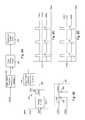
- FIG. 1illustrates a high level schematic diagram of a backlighting arrangement according to the prior art, illustrating an embodiment of the above open lamp condition detection.
- the backlighting arrangementcomprises a plurality of CCFLs 10 , a plurality of sense resistors RS each associated with a particular cold cathode fluorescent lamp 10 , a resistor RD 1 and a resistor RD 2 , a diode OR circuit 15 comprising a plurality of diodes DS each associated with a particular CCFL 10 , a controller 20 and a step-up transformer 90 .
- Controller 20comprises a pulse generator 30 , an open lamp detection functionality 35 and a lamp error amplifier 80 .
- Open lamp detection functionality 35comprises a comparator 40 , a comparator 50 , an OR gate 60 and an error cycle count functionality 70 .
- a received burst dimming pulse, denoted VBSTis connected to an input of pulse generator 30 .
- the output of pulse generator 30is connected to a first end of the primary winding of step-up transformer 90 , and the second end of the primary winding is connected to a first common point, illustrated as a chassis ground.
- a first end of the secondary winding of step-up transformer 90is connected to a second common point, which may be different from the common point of the primary winding, and is illustrated as a local ground.
- a second end of the secondary winding of step-up transformer 90is connected to a first end of resistor RD 1 and to a first end of each of the plurality of CCFLs 10 .
- each CCFL 10is connected to a first end of the associated sense resistor RS and to the anode of a particular one of the diodes DS of diode OR circuit 15 .
- the second end of each of the associated sense resistors RSare connected to the second common point.
- the second end of resistor RD 1is connected to a first end of resistor RD 2 and to the non-inverting input of comparator 40 , denoted input VSNS of controller 20 .
- the second end of resistor RD 2is connected to the second common point.
- a maximum voltage level, denoted VTH 2is connected to the inverting input of comparator 40 .
- the output of diode OR circuit 15is connected to the inverting input of comparator 50 and to the non-inverting input of error amplifier 80 , denoted input ISNS of controller 20 .
- An open lamp detection threshold current level, denoted VTH 1is connected to the non-inverting input of comparator 50 .
- the output of comparator 40is connected to a first input of OR gate 60 .
- the output of comparator 50is connected to a second input of OR gate 60 and via an inverter to the clear input of error cycle count functionality 70 .
- the output of OR gate 60is connected to the input of error cycle count functionality 70 .
- the output of error cycle count functionality 70denoted FAULT, is connected to an input of pulse generator 30 .
- a lamp current reference level, denoted IREFis connected to the inverting input of error amplifier 80 , and the output of error amplifier 80 is connected to an input of pulse generator 30 .
- Error cycle count functionality 70is illustrated as a digital counter, however this is not meant to be limiting in any way. In another embodiment error cycle count functionality 70 is implemented in an analog fashion with a capacitor arranged to receive a fixed current, and a fault signal will be output when a certain voltage level is reached.
- VBSTis illustrated as a received gating signal, however this is not meant to be limiting in any way.
- VBSTis derived from a received analog signal whose level is translated internally into the duty cycle for the burst dimming signal.
- pulse generator 30is operative to generate a pulse width modulated high frequency square wave gated by a low frequency burst dimming pulse VBST and thereby drive the primary side of step-up transformer 90 .
- pulse generator 30drives an H-bridge switching arrangement connected to the primary side of step up transformer 90 , as described in U.S. Pat. No. 5,930,121 to Henry, the entire contents of which is incorporated herein by reference.
- Step-up transformer 90steps up the voltage of the signal received at the primary, and in cooperation with self inductance of step-up transformer 90 and parasitic capacitance of CCFLs 10 , filters the resultant AC voltage to supply the AC voltage necessary for operation of CCFLs 10 .
- the voltage across the CCFLs 10is divided by the voltage divider of resistors RD 1 and RD 2 and the divided voltage is presented via input VSNS to be compared with maximum voltage level VTH 2 .
- the current through CCFLs 10are each sampled across the respective sense resistor RS, and the greater current is passed through diode OR circuit 15 and presented via input ISNS to be compared with open lamp detection threshold current level VTH 1 .
- the voltage representation of the current presented via input ISNSis further compared to lamp current reference level IREF, and any error is amplified and transmitted to pulse generator 30 which acts to increase or decrease the duty rate of the pulse width modulated output of pulse generator 30 so as to ensure that ISNS coincides with IREF when CCFLs 10 are being driven.
- Open lamp detection functionality 35is operative to compare the divided representation of the voltage across CCFLs 10 with maximum voltage level VTH 2 , and the representation of the greater current through the CCFLs 10 with open lamp detection threshold current level VTH 1 , and output an error signal to error cycle count functionality 70 whenever the divided representation of the voltage across CCFLs 10 exceeds maximum voltage level VTH 2 or the representation of the greater current through CCFLs 10 is less than open lamp detection threshold current level VTH 1 .
- Error cycle count functionality 70is operative to count a predetermined number of error conditions, i.e.
- the dimming frequencyis in the range of 150-250 Hz, which is well within the audible frequency range.
- An effective method to reduce such electro-mechanical vibrationis to control the profile of the burst lamp current so as to ramp up gradually when the burst dimming control changes from one state to another.
- the current resultant from the high frequency AC voltageis ramped up to the nominal value
- the current resultant from the high frequency AC voltageis ramped down from the nominal value until the lamp is off.
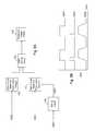
- FIG. 2illustrates a graph of certain signals of the backlighting arrangement of FIG. 1 , in which the x-axis represents a common time axis and the y-axis represents voltages in arbitrary units.
- the burst dimming signal, denoted VBSTin addition to VTH 1 and ISNS are illustrated.
- An additional analog representation of error cycle count functionality 70is shown, denoted Error_Count, and a trigger value above which assertion of the FAULT signal is asserted, denoted Fault_Level.
- the current through CCFLs 10is ramped up to its nominal value as shown by the ISNS representation.
- the burst dimmingis illustrated as being at a very low duty cycle, for instance around 10%, and therefore ISNS does not reach the VTH 1 level before being ramped back down.
- an additional error countis accumulated, as illustrated by the climbing of signal Error_Count. Error_Count is not cleared because of the failure of ISNS to be equal to, or greater than, VTH 1 . After a few cycles, Error_Count exceeds Fault Level, and the FAULT signal will thus be asserted, resulting in shut down of controller 20 .
- a backlighting arrangementin which shut down of the pulse generator responsive to open lamp current detection derived from the lamp current feedback signal is prevented whenever the burst dimming duty cycle is less than a predetermined value.
- the shut downis prevented by disabling a comparator associated with the lamp current feedback signal. In other embodiments the shut down is prevented by overriding the lamp current feedback signal with a predetermined voltage.
- the shut downis prevented by disabling a comparator associated with the lamp current feedback signal for a predetermined number of cycle periods of the pulse generator coincident with the rising edge of the burst dimming cycle. In other embodiments the shut down is prevented by overriding the lamp current feedback signal with a predetermined voltage for a predetermined number of cycle periods of the pulse generator coincident with the rising edge of the burst dimming cycle.
- the shut downis prevented by disabling an error counter for a predetermined number of cycle periods of the pulse generator coincident with the rising edge of the burst dimming cycle. In other embodiments the shut down is prevented by ramping a reference current signal for a predetermined number of cycle periods of the pulse generator coincident with the rising edge of the burst dimming.
- FIG. 1illustrates a high level schematic diagram of a backlighting arrangement including open lamp detection in accordance with the prior art
- FIG. 2illustrates a graph of certain signals of the backlighting arrangement of FIG. 1 ;
- FIG. 3illustrates a high level block diagram of a system operative to disable the open lamp current detection from lamp current feedback signal at low duty cycles according to an exemplary embodiment
- FIG. 4Aillustrates a high level block diagram of a system operative to pull up the lamp feedback signal to a level above the open lamp detection threshold and below the lamp current reference level for the entire burst on period according to an exemplary embodiment
- FIG. 4Billustrates a graph of certain signals of the system of FIG. 4A ;
- FIG. 5Aillustrates a high level block diagram of a system operative to disable the open lamp current detection from lamp current feedback signal for a short period at the burst dimming rising edge according to an exemplary embodiment
- FIG. 5Billustrates a graph of certain signals of the system of FIG. 5A ;
- FIG. 6Aillustrates a high level block diagram of a system operative to pull up the lamp feedback signal to a value above the open lamp threshold and below the lamp current reference signal for a short period at the burst dimming rising edge, according to an exemplary embodiment
- FIG. 6Billustrates a graph of certain signals of the system of FIG. 6A ;
- FIG. 7Aillustrates a high level block diagram of a system operative to provide a pre-offset to the open lamp timing circuit at the burst dimming rising edge, according to an exemplary embodiment
- FIG. 7Billustrates a graph of certain signals of the system of FIG. 7A ;
- FIG. 8Aillustrates a high level block diagram of a system operative to adjust the open lamp current threshold level at the burst dimming rising edge, according to an exemplary embodiment comprising an electronically controlled switch;
- FIG. 8Billustrates a high level schematic diagram of a disable circuit providing a sloped rise for the effective open lamp detection threshold current level being compared with the sensed lamp current;
- FIG. 8Cillustrates a graph of certain signals of the system of FIG. 8A ;
- FIG. 8Dillustrates a graph of certain signals of the system of FIG. 8B .
- FIG. 9is a high level flow chart of the method of operation of each of FIGS. 3-8B .
- FIG. 3illustrates a high level block diagram of a system comprising an open lamp detection from lamp voltage functionality 100 , an open lamp detection from lamp current functionality 110 , a fault timing circuit 120 , a protection trigger circuit 130 , a low burst dimming level detection functionality 140 , a lamp voltage feedback signal VSNS and a lamp current feedback signal ISNS.
- Fault timing circuit 120is comprised of an analog capacitor charging circuit, or a digital counting circuit as described above in relation to error cycle count functionality 70 of FIG. 1 .
- Lamp voltage feedback signal VSNSis connected to the input of open lamp detection from lamp voltage functionality 100 , and the output of open lamp detection from lamp voltage functionality 100 is connected to a first input of fault timing circuit 120 .
- Lamp current feedback signal ISNSis connected to the input of open lamp detection from lamp current functionality 110 and the output of open lamp detection from lamp current functionality 110 is connected to a second input of fault timing circuit 120 .
- Protection trigger circuit 130is connected to the output of fault timing circuit 120 and low burst dimming level detection functionality 140 is connected to open lamp detection from lamp current functionality 110 .
- Open lamp detection from lamp voltage functionality 100is in one embodiment implemented as described above in relation to comparator 40 of FIG. 1 .
- Open lamp detection from lamp current functionality 110is in one embodiment implemented as described above in relation to comparator 50 of FIG. 1 , with the exception that comparator 50 is replaced with a comparator having an disable input. In the event that the disable input is asserted, the output of the comparator is set to low.
- an error signalis sent to fault timing circuit 120 . If the error signal is sustained for a specific amount of time an open lamp is detected, as described above in relation to FIG. 1 and FIG. 2 , and protection trigger circuit 130 is operative to shut down the inverter. At low burst duty cycles, such as around 10% and below, low burst dimming level detection functionality 140 is operative to detect the low burst dimming level and disable open lamp detection from lamp current functionality 110 . While open lamp detection from lamp current functionality 110 is disabled, if an open lamp exists it will be detected by open lamp detection from lamp voltage functionality 100 .
- FIG. 4Aillustrates a high level block diagram of a system comprising an open lamp detection from lamp voltage functionality 100 , an open lamp detection from lamp current functionality 110 , a fault timing circuit 120 , a protection trigger circuit 130 , a low burst dimming level detection functionality 150 , a lamp voltage feedback signal VSNS, a lamp current feedback signal ISNS, and a unidirectional circuit shown as diode D.
- Fault timing circuit 120is comprised of an analog capacitor charging circuit, or a digital counting circuit as described above in relation to error cycle count functionality 70 of FIG. 1 .
- Lamp voltage feedback signal VSNSis connected to the input of open lamp detection from lamp voltage functionality 100 , and the output of open lamp detection from lamp voltage functionality 100 is connected to a first input of fault timing circuit 120 .
- Lamp current feedback signal ISNSis connected to the input of open lamp detection from lamp current functionality 110 and the output of open lamp detection from lamp current functionality 110 is connected to a second input of fault timing circuit 120 .
- Protection trigger circuit 130is connected to the output of fault timing circuit 120 .
- the output of low burst dimming level detection functionality 150denoted VPULL, is connected via unidirectional circuit D to lamp current feedback signal ISNS.
- Open lamp detection from lamp voltage functionality 100is in one embodiment implemented as described above in relation to comparator 40 of FIG. 1 .
- Open lamp detection from lamp current functionality 110is in one embodiment implemented as described above in relation to comparator 50 of FIG. 1 .
- low burst dimming level detection functionality 150is operative to detect the low burst dimming level and output a voltage clamping level VPULL, selected to be above open lamp detection threshold current level VTH 1 of FIG. 1 and FIG. 2 and below lamp current reference level IREF of FIG. 1 .
- the output of low burst dimming level detection functionality 150is channeled by unidirectional circuit D to pull up lamp current feedback signal ISNS.
- unidirectional circuit DWhen the voltage representation of the lamp current rises above clamping voltage VPULL the clamp circuit is cut off, i.e. unidirectional circuit D becomes reverse biased and becomes open, and error amplifier 80 of FIG. 1 resumes to control the lamp current feedback signal ISNS at lamp current reference level IREF.
- FIG. 4Billustrates a graph of certain signals of the embodiment of FIG. 4A , in which the x-axis represents a common time axis and the y-axis represents voltages in arbitrary units.
- Signals VBST and ISNSare illustrated as well as reference levels IREF and VTH 1 .
- lamp current feedback signal ISNSis pulled up to a clamping level, VPULL, above open lamp detection threshold VTH 1 and below lamp current reference level IREF.
- FIG. 5Aillustrates a high level block diagram of a system comprising an open lamp detection from lamp voltage functionality 100 , an open lamp detection from lamp current functionality 110 , a fault timing circuit 120 , a protection trigger circuit 130 , a lamp voltage feedback signal VSNS, a lamp current feedback signal ISNS, a timing circuit 160 , and a burst dimming pulse denoted VBST.
- Fault timing circuit 120is comprised of an analog capacitor charging circuit, or a digital counting circuit as described above in relation to error cycle count functionality 70 of FIG. 1 .
- Lamp voltage feedback signal VSNSis connected to the input of open lamp detection from lamp voltage functionality 100 , and the output of open lamp detection from lamp voltage functionality 100 is connected to a first input of fault timing circuit 120 .
- Lamp current feedback signal ISNSis connected to the input of open lamp detection from lamp current functionality 110 and the output of open lamp detection from lamp current functionality 110 is connected to a second input of fault timing circuit 120 .
- Protection trigger circuit 130is connected to the output of fault timing circuit 120 .
- Timing circuit 160is connected to receive burst dimming pulse VBST and to output a signal denoted VINH which is received by open lamp detection from lamp current functionality 110 .
- Open lamp detection from lamp voltage functionality 100is in one embodiment implemented as described above in relation to comparator 40 of FIG. 1 .
- Open lamp detection from lamp current functionality 110is in one embodiment implemented as described above in relation to comparator 50 of FIG. 1 , with the exception that comparator 50 is replaced with a comparator having an disable input. In the event that the disable input is asserted, the output of the comparator is set to low.
- Timing circuit 160may be implemented as one of an analog and digital timing circuit.
- timing circuit 120In operation, if one of open lamp detection from lamp voltage functionality 100 and open lamp detection from lamp current functionality 110 detects an open lamp, an error signal is sent to fault timing circuit 120 . If the error signal is sustained for a specific amount of time an open lamp is detected, as described above in relation to FIG. 1 and FIG. 2 , and protection trigger circuit 130 is operative to shut down the inverter. At the rise of burst dimming pulse VBST, timing circuit 160 enables signal VINH to disable open lamp detection from lamp current feedback signal for a number of cycles.
- open lamp detection from lamp current feedbackcan be disabled by timing circuit 160 for a short period and resume thereafter.
- Open lamp detectionis normally disabled during the entire burst off period including the falling edge of the burst on period, therefore disabling of the open lamp detection is only necessary during the rise of burst dimming pulse VBST.
- FIG. 5Billustrates a graph of certain signals of the embodiment of FIG. 5A , in which the x-axis represents a common time axis and the y-axis represents voltages in arbitrary units.
- Signals VBST, VINH and ISNSare illustrated as well as reference level VTH 1 .
- signal VINHdisables the open lamp detection from lamp current feedback for a portion of burst dimming pulse VBST, thereby preventing false detection of an open lamp while lamp current feedback signal ISNS is below open lamp detection threshold VTH 1 .
- VINHwill effectively prevent detection of an open lamp due to failure of ISNS to achieve the level VTH 1 .
- FIG. 6Aillustrates a high level block diagram of a system comprising an open lamp detection from lamp voltage functionality 100 , an open lamp detection from lamp current functionality 110 , a fault timing circuit 120 , a protection trigger circuit 130 , a lamp voltage feedback signal VSNS, a lamp current feedback signal ISNS, a timing circuit 170 , a burst dimming pulse VBST and a unidirectional circuit D, illustrated as a diode.
- Fault timing circuit 120is comprised of an analog capacitor charging circuit, or a digital counting circuit as described above in relation to error cycle count functionality 70 of FIG. 1 .
- Lamp voltage feedback signal VSNSis connected to the input of open lamp detection from lamp voltage functionality 100 , and the output of open lamp detection from lamp voltage functionality 100 is connected to a first input of fault timing circuit 120 .
- Lamp current feedback signal ISNSis connected to the input of open lamp detection from lamp current functionality 110 and the output of open lamp detection from lamp current functionality 110 is connected to a second input of fault timing circuit 120 .
- Protection trigger circuit 130is connected to the output of fault timing circuit 120 .
- Timing circuit 170is connected to receive burst dimming pulse VBST and to output a signal denoted VPULL which is connected via unidirectional circuit D to lamp current feedback signal ISNS, and is operative to clamp ISNS to a minimum value of VPULL when active.
- Open lamp detection from lamp voltage functionality 100is in one embodiment implemented as described above in relation to comparator 40 of FIG. 1 .
- Open lamp detection from lamp current functionality 110is in one embodiment implemented as described above in relation to comparator 50 of FIG. 1 .
- Timing circuit 170may be implemented as one of an analog and digital timing circuit.
- timing circuit 170In operation, if one of open lamp detection from lamp voltage functionality 100 and open lamp detection from lamp current functionality 110 detects an open lamp, an error signal is sent to fault timing circuit 120 . If the error signal is sustained for a specific amount of time an open lamp is detected, as described above in relation to FIG. 1 and FIG. 2 , and protection trigger circuit 130 is operative to shut down the inverter. At the rise of burst dimming pulse VBST, timing circuit 170 outputs signal VPULL which pulls up ISNS, for a predetermined number of cycles, to a minimum level above open lamp detection threshold VTH 1 of FIGS. 1 , 2 and below lamp current reference level IREF.
- FIG. 6Billustrates a graph of certain signals of the embodiment of FIG. 6A , in which the x-axis represents a common time axis and the y-axis represents voltages in arbitrary units.
- Signals VBST, VPULL and ISNSare illustrated as well as reference level VTH 1 and IREF.
- VPULLAs described above in FIG. 6A at the rise of burst dimming pulse VBST signal VPULL is asserted for a predetermined short period thereby clamping lamp current feedback signal ISNS to a minimum level above open lamp detection threshold VTH 1 and below current reference level IREF.
- VPULLwill effectively prevent detection of an open lamp due to failure of ISNS to achieve the level VTH 1 .
- FIG. 7Aillustrates a high level block diagram of a system comprising an open lamp detection from lamp voltage functionality 100 , an open lamp detection from lamp current functionality 110 , a fault timing circuit 120 , a protection trigger circuit 130 , a lamp voltage feedback signal VSNS, a lamp current feedback signal ISNS, a timing circuit 180 , and a burst dimming pulse VBST.
- Fault timing circuit 120is comprised of an analog capacitor charging circuit, or a digital counting circuit as described above in relation to error cycle count functionality 70 of FIG. 1 .
- Lamp voltage feedback signal VSNSis connected to the input of open lamp detection from lamp voltage functionality 100 , and the output of open lamp detection from lamp voltage functionality 100 is connected to a first input of fault timing circuit 120 .
- Lamp current feedback signal ISNSis connected to the input of open lamp detection from lamp current functionality 110 and the output of open lamp detection from lamp current functionality 110 is connected to a second input of fault timing circuit 120 .
- Protection trigger circuit 130is connected to the output of fault timing circuit 120 .
- Timing circuit 180is connected to receive burst dimming pulse VBST and to output a pre-offset signal denoted VOFFSET which is received by fault timing circuit 120 .
- Fault timing circuit 120outputs a fault signal denoted VFAULT which is received by protection trigger circuit 130 .
- Open lamp detection from lamp voltage functionality 100is in one embodiment implemented as described above in relation to comparator 40 of FIG. 1 .
- Open lamp detection from lamp current functionality 110is in one embodiment implemented as described above in relation to comparator 50 of FIG. 1 .
- Timing circuit 180may be implemented as one of an analog and digital timing circuit.
- fault timing circuit 120In operation, if one of open lamp detection from lamp voltage functionality 100 and open lamp detection from lamp current functionality 110 detects an open lamp, an error signal is sent to fault timing circuit 120 . If the error signal is sustained for a specific amount of time an open lamp is detected, as described above in relation to FIG. 1 and FIG. 2 , and protection trigger circuit 130 is operative to shut down the inverter. As described above, in order to avoid transient response, typically fault timing circuit 120 requires the error signal to be valid for a plurality of burst cycles and only then outputs fault signal VFAULT to protection trigger circuit 130 thereby shutting down the operation of the lamp, in one embodiment by outputting the FAULT signal of FIG. 1 .
- timing circuit 180sends pre-offset signal VOFFSET to fault timing circuit 120 .
- Pre-offset signal VOFFSETprovides a pre-determined discharge for the timing capacitor if fault timing circuit 120 is an analog capacitor charging circuit, or a pre-determined decrement of the fault timing counter if fault timing circuit 120 is a digital counting circuit.
- the amount of pre-offset provided, i.e. the discharge for the timing capacitor or the decrement count of the fault timing counter,is set to be equal or slightly greater than the incremental timing effect caused by the open lamp detection at the rising edge of burst dimming pulse VBST.
- pre-offset signal VOFFSETis provided at the falling edge of burst dimming pulse VBST.
- FIG. 7Billustrates a graph of certain signals of the embodiment of FIG. 7A , in which the x-axis represents a common time axis and the y-axis represents voltages in arbitrary units.
- Signals VBST, VOFFSET, ISNS and VFAULTare illustrated as well as reference level VTH 1 and FAULT_LEVEL.
- protection trigger circuit 130requires the error signal to be valid for a plurality of burst cycles, until fault signal VFAULT rises to fault level FAULT_LEVEL, and only then protection trigger circuit 130 is operative to shut down the operation of the inverter.
- fault signal VFAULTis below fault level FAULT_LEVEL.
- pre-offset signal VOFFSETis activated thereby lowering fault signal VFAULT by a predetermined offset.
- Fault signal VFAULTbegins to rise for each cycle where lamp current feedback signal ISNS is below open lamp detection threshold VTH 1 .
- ISNSwould rise above VTH 1 , thereby clearing VFAULT, as described above in relation to FIG. 1 .
- the offset provided by VOFFSETprevents false triggering of protection trigger circuit 130 .
- FIG. 8Aillustrates a high level block diagram of a system comprising an open lamp detection from lamp voltage functionality 100 , an open lamp detection from lamp current functionality 110 , a fault timing circuit 120 , a protection trigger circuit 130 , a lamp voltage feedback signal VSNS, a lamp current feedback signal ISNS, an open lamp detection threshold current level VTH 1 , a burst dimming pulse VBST, and a disable circuit 200 comprising a timing circuit 210 , an electronically controlled switch 220 , and a resistor 230 .
- Fault timing circuit 120is comprised of an analog capacitor charging circuit, or a digital counting circuit as described above in relation to error cycle count functionality 70 of FIG. 1 .
- Lamp voltage feedback signal VSNSis connected to the input of open lamp detection from lamp voltage functionality 100 , and the output of open lamp detection from lamp voltage functionality 100 is connected to a first input of fault timing circuit 120 .
- Lamp current feedback signal ISNSis connected to a first input of open lamp detection from lamp current functionality 110 and the output of open lamp detection from lamp current functionality 110 is connected to a second input of fault timing circuit 120 .
- Protection trigger circuit 130is connected to the output of fault timing circuit 120 .
- Value detection circuit 210is connected to receive burst dimming pulse VBST and to output a corresponding signal when VBST is less than a predetermined value, with the output of timing circuit 210 connected to the gate of electronically controlled switch 220 .
- Open lamp detection threshold current level VTH 1is connected to a first end of resistor 230 , and a second end of resistor 230 carrying a signal denoted VTH 1 ′ is connected to a second input of open lamp detection from lamp current functionality 110 , and to the drain of electronically controlled switch 220 .
- the source of electronically controlled switch 220is connected to a common point, shown as ground.
- Open lamp detection from lamp voltage functionality 100is in one embodiment implemented as described above in relation to comparator 40 of FIG. 1 .
- Open lamp detection from lamp current functionality 110is in one embodiment implemented as described above in relation to comparator 50 of FIG. 1 .
- Value detection circuitry 200may be implemented as an analog or a digital circuit.
- fault timing circuit 120In operation, if one of open lamp detection from lamp voltage functionality 100 and open lamp detection from lamp current functionality 110 detects an open lamp, an error signal is sent to fault timing circuit 120 . If the error signal is sustained for a specific amount of time an open lamp is detected, as described above in relation to FIG. 1 and FIG. 2 , and protection trigger circuit 130 is operative to shut down the inverter. As described above, in order to avoid transient response, typically fault timing circuit 120 requires the error signal to be valid for a plurality of burst cycles and only then outputs fault signal VFAULT to protection trigger circuit 130 thereby shutting down the operation of the lamp, in one embodiment by outputting the FAULT signal of FIG. 1 .
- Burst dimming pulse VBSTis received at timing circuit 210 .
- timing circuit 210closes electronically controlled switch 220 for a number of cycles which acts to pull down VTH 1 ′ to a low level, such as ground, and preferably maintain VTH 1 ′. Since there is only a short period, normally less than 10 lamp frequency cycles, at the rising edge of burst dimming pulse VBST that a false open lamp would be seen from the lamp current feedback, open lamp detection from lamp current feedback can be disabled by timing circuit 210 by pulling down signal VTH 1 ′ received by open lamp detection from lamp current functionality 110 for a short period and allowing open lamp detection from lamp current functionality 110 to receive VTH thereafter. Open lamp detection is normally disabled during the entire burst off period including the falling edge of the burst on period, therefore disabling of the open lamp detection is only necessary during the rise of burst dimming pulse VBST.
- disable circuit 200comprises resistor 230 , a capacitor 240 and a unidirectional circuit 250 .
- Open lamp detection threshold current level VTH 1is connected to a first end of resistor 230
- a second end of resistor 230 carrying a signal denoted VTH 1 ′is connected to a second input of open lamp detection from lamp current functionality 110 , to a first end of capacitor 240 and to the anode of unidirectional circuit 250 .
- the second end of capacitor 240is connected to a common point of low value, illustrated as ground.
- the cathode of unidirectional circuit 250is connected to burst dimming pulse VBST.
- values for resistor 230 and capacitor 240are selected so that at the rising edge of VBST, VTH 1 ′ rises slower than ISNS, and remains lower than ISNS until ISNS reaches its steady state value.
- VTH 1 ′rises slower than ISNS, and remains lower than ISNS until ISNS reaches its steady state value.
- VTH 1 ′rises slower than ISNS, and remains lower than ISNS until ISNS reaches its steady state value.
- VTH 1 ′is pulled down, and upon the rising edge of all burst dimming cycles, VTH 1 ′ is sloped by the charging of capacitor 240 through resistor 230 .
- an open lampis detected when lamp current feedback signal ISNS is below the open lamp detection threshold current level, in the present embodiment VTH 1 ′.
- ISNSwill be greater than VTH 1 ′ thereby avoiding a false open lamp detection.
- Open lamp detectionis normally disabled during the entire burst off period including the falling edge of the burst on period, therefore disabling of the open lamp detection
- FIG. 8Cillustrates a graph of certain signals of the embodiment of FIG. 8A , in which the x-axis represents a common time axis and the y-axis represents voltages in arbitrary units.
- Signals VBST, VTH 1 ′ and ISNSare illustrated as well as reference level VTH 1 .
- VTH 1 ′At each rising edge of burst dimming pulse VBST, optionally only when the burst of VBST is less than a predetermined value, the value of VTH 1 ′ is pulled down to a low level, optionally to ground, thereby being less than the expected value of ISNS. The low level is maintained for a sufficient amount of time for ISNS to rise to its steady state value. As a result no error is detected for low burst dimming cycles.
- FIG. 8Dillustrates a graph of certain signals of the embodiment of FIG. 8A , in which the x-axis represents a common time axis and the y-axis represents voltages in arbitrary units.
- Signals VBST, VTH 1 ′ and ISNSare illustrated as well as reference level VTH 1 .
- VTH 1 ′At each burst of VBST, the value of VTH 1 ′ is pulled down to a low level, optionally to ground, and VTH 1 ′ rises slowly after being pulled down, consistently being less than the expected value of ISNS caused by the sloped burst dimming cycle rising edge. As a result no error is detected for low burst dimming cycles.
- FIG. 9is a high level flow chart of the method of operation of each of the embodiments of FIG. 3-8B .
- a representation of a current through a loadsuch as ISNS, supplied responsive to a power source, is compared with a reference value, such as VTH 1 .
- stage 1010in the event that the compared representation of the current of stage 1000 is not less than the reference for a predetermined period, described above as a predetermined number of cycles of the power source, stage 1000 is repeated.
- stage 1020the burst dimming value is compared with a predetermined minimum burst value.
- the predetermined minimum burst valueis selected in cooperation with the burst dimming slope so that a false open error is not triggered.
- the power sourceis at least partially shut down and stage 1000 , as described above, is performed.
- stage 1040the shut down of stage 1030 is disabled.
- the disabling of stage 1040is accomplished by preventing the comparing of stage 1000 , optionally for a particular period coincident with the rising edge of the burst dimming cycle, as described above in relation to FIGS. 3 , 5 A and 5 B.
- stage 1060the disabling of stage 1040 is accomplished by providing a predetermined voltage level overriding the representation of the current, optionally for a particular period coincident with the rising edge of the burst dimming cycle, as described above in relation to FIGS. 4A , 4 B, 6 A, 6 B.
- stage 1070the disabling of stage 1040 is accomplished by preventing the marking of the period of stage 1010 being exceeded, optionally for a particular period coincident with the rising edge of the burst dimming cycle, as described above in relation to FIGS. 7A , 7 B.
- stage 1080the disabling of stage 1040 is accomplished by adjusting the reference signal of stage 1000 coincident with the rising edge of the burst dimming cycle, as described above in relation to FIGS. 8A-8D .
- adjusting the reference is signalis accomplished by one of pulling the reference signal to a predetermined value and ramping the reference signal from a predetermined value to its nominal value.
- the present embodimentsenable burst dimming at low duty cycles without causing false open lamp detection. This is accomplished in one embodiment by disabling the open lamp current detection at low duty cycles, usually below 10%. In another embodiment the open lamp current detection is disabled completely during operation. In another embodiment the lamp current feedback signal is pulled up to a level above the open lamp detection threshold during the burst on period. In yet another embodiment lamp current detection is disabled for a number of cycles at the rise of burst dimming. Open lamp detection is normally disabled during the entire burst off period including the falling edge and therefore disabling of lamp current detection is needed only at the rising edge. In another embodiment the lamp current feedback signal is pulled up to a level above the open lamp detection threshold for a short period, the short period being equal or longer than the time to rise to the threshold, during the burst on edge.
- a pre-offsetis provided to the open lamp timing circuit at the burst dimming rising edge to prevent false open lamp detection.
- the pre-offsetprovides a pre-determined discharge for the timing capacitor, or a pre-determined decrement of the timing counter, at the rising edge of burst dimming.
- the amount of pre-offseti.e. the discharge timing capacitor or the decrement count of the fault timing counter, is set to be equal or slightly greater than the incremental timing effect caused by the open lamp detection at the rising edge of the burst on duty.
- the open lamp detection threshold signalis ramped up to the nominal value over a predetermined number of cycle periods of the pulse generator coincident with the rising edge of the burst dimming duty cycle.
Landscapes
- Circuit Arrangements For Discharge Lamps (AREA)
- Discharge-Lamp Control Circuits And Pulse- Feed Circuits (AREA)
Abstract
Description
Claims (20)
Priority Applications (1)
| Application Number | Priority Date | Filing Date | Title |
|---|---|---|---|
| US12/610,327US8093839B2 (en) | 2008-11-20 | 2009-11-01 | Method and apparatus for driving CCFL at low burst duty cycle rates |
Applications Claiming Priority (2)
| Application Number | Priority Date | Filing Date | Title |
|---|---|---|---|
| US11630208P | 2008-11-20 | 2008-11-20 | |
| US12/610,327US8093839B2 (en) | 2008-11-20 | 2009-11-01 | Method and apparatus for driving CCFL at low burst duty cycle rates |
Publications (2)
| Publication Number | Publication Date |
|---|---|
| US20100123400A1 US20100123400A1 (en) | 2010-05-20 |
| US8093839B2true US8093839B2 (en) | 2012-01-10 |
Family
ID=42171455
Family Applications (1)
| Application Number | Title | Priority Date | Filing Date |
|---|---|---|---|
| US12/610,327Expired - Fee RelatedUS8093839B2 (en) | 2008-11-20 | 2009-11-01 | Method and apparatus for driving CCFL at low burst duty cycle rates |
Country Status (1)
| Country | Link |
|---|---|
| US (1) | US8093839B2 (en) |
Cited By (4)
| Publication number | Priority date | Publication date | Assignee | Title |
|---|---|---|---|---|
| US20100128016A1 (en)* | 2007-09-28 | 2010-05-27 | Fujitsu Limited | Lighting device for cold-cathode tube and control method thereof |
| US20110101889A1 (en)* | 2008-07-08 | 2011-05-05 | Koninklijke Philips Electronics N.V. | Methods and apparatus for determining relative positions of led lighting units |
| US20120099354A1 (en)* | 2010-10-22 | 2012-04-26 | Gao Jianlong | Circuits and methods for alternating current-to-direct current conversion |
| US20140111089A1 (en)* | 2012-10-23 | 2014-04-24 | Osram Sylvania Inc. | Latching circuit for ballast |
Families Citing this family (1)
| Publication number | Priority date | Publication date | Assignee | Title |
|---|---|---|---|---|
| JP6247455B2 (en)* | 2013-05-17 | 2017-12-13 | ローム株式会社 | LIGHT EMITTING ELEMENT DRIVE CIRCUIT, AND LIGHT EMITTING DEVICE AND ELECTRONIC DEVICE USING THE SAME |
Citations (379)
| Publication number | Priority date | Publication date | Assignee | Title |
|---|---|---|---|---|
| US2429162A (en) | 1943-01-18 | 1947-10-14 | Boucher And Keiser Company | Starting and operating of fluorescent lamps |
| US2440984A (en) | 1945-06-18 | 1948-05-04 | Gen Electric | Magnetic testing apparatus and method |
| US2572258A (en) | 1946-07-20 | 1951-10-23 | Picker X Ray Corp Waite Mfg | X-ray tube safety device |
| US2965799A (en) | 1957-09-26 | 1960-12-20 | Gen Electric | Fluorescent lamp ballast |
| US2968028A (en) | 1956-06-21 | 1961-01-10 | Fuje Tsushinki Seizo Kabushiki | Multi-signals controlled selecting systems |
| US3141112A (en) | 1962-08-20 | 1964-07-14 | Gen Electric | Ballast apparatus for starting and operating electric discharge lamps |
| US3449629A (en) | 1968-05-16 | 1969-06-10 | Westinghouse Electric Corp | Light,heat and temperature control systems |
| US3565806A (en) | 1965-11-23 | 1971-02-23 | Siemens Ag | Manganese zinc ferrite core with high initial permeability |
| US3597656A (en) | 1970-03-16 | 1971-08-03 | Rucker Co | Modulating ground fault detector and interrupter |
| US3611021A (en) | 1970-04-06 | 1971-10-05 | North Electric Co | Control circuit for providing regulated current to lamp load |
| US3683923A (en) | 1970-09-25 | 1972-08-15 | Valleylab Inc | Electrosurgery safety circuit |
| US3737755A (en) | 1972-03-22 | 1973-06-05 | Bell Telephone Labor Inc | Regulated dc to dc converter with regulated current source driving a nonregulated inverter |
| US3742330A (en) | 1971-09-07 | 1973-06-26 | Delta Electronic Control Corp | Current mode d c to a c converters |
| US3916283A (en) | 1975-02-10 | 1975-10-28 | Pylon Electronic Dev | DC to DC Converter |
| US3936696A (en) | 1973-08-27 | 1976-02-03 | Lutron Electronics Co., Inc. | Dimming circuit with saturated semiconductor device |
| US3944888A (en) | 1974-10-04 | 1976-03-16 | I-T-E Imperial Corporation | Selective tripping of two-pole ground fault interrupter |
| US4053813A (en) | 1976-03-01 | 1977-10-11 | General Electric Company | Discharge lamp ballast with resonant starting |
| US4060751A (en) | 1976-03-01 | 1977-11-29 | General Electric Company | Dual mode solid state inverter circuit for starting and ballasting gas discharge lamps |
| US4194147A (en) | 1977-12-05 | 1980-03-18 | Burr-Brown Research Corporation | Parallel connected switching regulator system |
| US4204141A (en) | 1978-09-11 | 1980-05-20 | Esquire, Inc. | Adjustable DC pulse circuit for variation over a predetermined range using two timer networks |
| US4257090A (en) | 1977-12-09 | 1981-03-17 | Dornier System Gmbh | Circuit for defined current sharing between parallel-connected switching regulator modules in DC switching regulators |
| US4276590A (en) | 1979-04-30 | 1981-06-30 | The Perkin-Elmer Corporation | Current sharing modular power system |
| US4277728A (en) | 1978-05-08 | 1981-07-07 | Stevens Luminoptics | Power supply for a high intensity discharge or fluorescent lamp |
| US4307441A (en) | 1980-07-28 | 1981-12-22 | United Technologies Corporation | Current balanced DC-to-DC converter |
| US4353009A (en) | 1980-12-19 | 1982-10-05 | Gte Products Corporation | Dimming circuit for an electronic ballast |
| US4359679A (en) | 1978-01-16 | 1982-11-16 | Wescom Switching, Inc. | Switching d-c. regulator and load-sharing system for multiple regulators |
| US4386394A (en) | 1981-05-20 | 1983-05-31 | General Electric Company | Single phase and three phase AC to DC converters |
| US4388562A (en) | 1980-11-06 | 1983-06-14 | Astec Components, Ltd. | Electronic ballast circuit |
| US4392087A (en) | 1980-11-26 | 1983-07-05 | Honeywell, Inc. | Two-wire electronic dimming ballast for gaseous discharge lamps |
| US4425613A (en) | 1981-05-26 | 1984-01-10 | Sperry Corporation | Forced load sharing circuit for inverter power supply |
| US4437042A (en) | 1981-12-10 | 1984-03-13 | General Electric Company | Starting and operating circuit for gaseous discharge lamps |
| US4441054A (en) | 1982-04-12 | 1984-04-03 | Gte Products Corporation | Stabilized dimming circuit for lamp ballasts |
| US4463287A (en) | 1981-10-07 | 1984-07-31 | Cornell-Dubilier Corp. | Four lamp modular lighting control |
| US4469988A (en) | 1980-06-23 | 1984-09-04 | Cronin Donald L | Electronic ballast having emitter coupled transistors and bias circuit between secondary winding and the emitters |
| US4480201A (en) | 1982-06-21 | 1984-10-30 | Eaton Corporation | Dual mode power transistor |
| US4523130A (en) | 1981-10-07 | 1985-06-11 | Cornell Dubilier Electronics Inc. | Four lamp modular lighting control |
| US4543522A (en) | 1982-11-30 | 1985-09-24 | Thomson-Csf | Regulator with a low drop-out voltage |
| US4544863A (en) | 1984-03-22 | 1985-10-01 | Ken Hashimoto | Power supply apparatus for fluorescent lamp |
| US4555673A (en) | 1984-04-19 | 1985-11-26 | Signetics Corporation | Differential amplifier with rail-to-rail input capability and controlled transconductance |
| US4562338A (en) | 1983-07-15 | 1985-12-31 | Osaka Titanium Co., Ltd. | Heating power supply apparatus for polycrystalline semiconductor rods |
| US4567379A (en) | 1984-05-23 | 1986-01-28 | Burroughs Corporation | Parallel current sharing system |
| US4572992A (en) | 1983-06-16 | 1986-02-25 | Ken Hayashibara | Device for regulating ac current circuit |
| US4574222A (en) | 1983-12-27 | 1986-03-04 | General Electric Company | Ballast circuit for multiple parallel negative impedance loads |
| US4585974A (en) | 1983-01-03 | 1986-04-29 | North American Philips Corporation | Varible frequency current control device for discharge lamps |
| US4618779A (en) | 1984-06-22 | 1986-10-21 | Storage Technology Partners | System for parallel power supplies |
| US4622496A (en) | 1985-12-13 | 1986-11-11 | Energy Technologies Corp. | Energy efficient reactance ballast with electronic start circuit for the operation of fluorescent lamps of various wattages at standard levels of light output as well as at increased levels of light output |
| US4626770A (en) | 1985-07-31 | 1986-12-02 | Motorola, Inc. | NPN band gap voltage reference |
| US4630005A (en) | 1982-05-03 | 1986-12-16 | Brigham Young University | Electronic inverter, particularly for use as ballast |
| US4635178A (en) | 1983-11-04 | 1987-01-06 | Ceag Electric Corp. | Paralleled DC power supplies sharing loads equally |
| US4663566A (en) | 1984-02-03 | 1987-05-05 | Sharp Kabushiki Kaisha | Fluorescent tube ignitor |
| US4663570A (en) | 1984-08-17 | 1987-05-05 | Lutron Electronics Co., Inc. | High frequency gas discharge lamp dimming ballast |
| US4672300A (en) | 1985-03-29 | 1987-06-09 | Braydon Corporation | Direct current power supply using current amplitude modulation |
| US4675574A (en) | 1985-06-20 | 1987-06-23 | N.V. Adb S.A. | Monitoring device for airfield lighting system |
| US4682080A (en) | 1984-08-17 | 1987-07-21 | Hitachi, Ltd. | Discharge lamp operating device |
| US4686615A (en) | 1985-08-23 | 1987-08-11 | Ferranti, Plc | Power supply circuit |
| US4689802A (en) | 1986-05-22 | 1987-08-25 | Chrysler Motors Corporation | Digital pulse width modulator |
| US4698554A (en) | 1983-01-03 | 1987-10-06 | North American Philips Corporation | Variable frequency current control device for discharge lamps |
| US4698738A (en) | 1986-11-24 | 1987-10-06 | Unisys Corporation | Parallel connected power supplies having parallel connected control circuits which equalize output currents to a load even after one supply is turned off |
| US4700113A (en) | 1981-12-28 | 1987-10-13 | North American Philips Corporation | Variable high frequency ballast circuit |
| US4717833A (en) | 1984-04-30 | 1988-01-05 | Boschert Inc. | Single wire current share paralleling of power supplies |
| US4717863A (en) | 1986-02-18 | 1988-01-05 | Zeiler Kenneth T | Frequency modulation ballast circuit |
| US4724374A (en) | 1987-02-09 | 1988-02-09 | Westinghouse Electric Corp. | Solid state current limited power controller for DC circuits |
| US4729086A (en) | 1987-07-17 | 1988-03-01 | Unisys Corporation | Power supply system which shares current from a single redundant supply with multiple segmented loads |
| US4734844A (en) | 1987-06-08 | 1988-03-29 | Ncr Corporation | Master/slave current sharing, PWM power supply |
| US4745339A (en) | 1985-04-12 | 1988-05-17 | Kabushiki Kaisha Tokai Rika Denki Seisakusho | Lamp failure detecting device for automobile |
| US4761722A (en) | 1987-04-09 | 1988-08-02 | Rca Corporation | Switching regulator with rapid transient response |
| US4766353A (en) | 1987-04-03 | 1988-08-23 | Sunlass U.S.A., Inc. | Lamp switching circuit and method |
| US4779037A (en) | 1987-11-17 | 1988-10-18 | National Semiconductor Corporation | Dual input low dropout voltage regulator |
| US4780696A (en) | 1985-08-08 | 1988-10-25 | American Telephone And Telegraph Company, At&T Bell Laboratories | Multifilar transformer apparatus and winding method |
| US4792747A (en) | 1987-07-01 | 1988-12-20 | Texas Instruments Incorporated | Low voltage dropout regulator |
| US4812781A (en) | 1987-12-07 | 1989-03-14 | Silicon General, Inc. | Variable gain amplifier |
| US4825144A (en) | 1987-11-10 | 1989-04-25 | Motorola, Inc. | Dual channel current mode switching regulator |
| US4847745A (en) | 1988-11-16 | 1989-07-11 | Sundstrand Corp. | Three phase inverter power supply with balancing transformer |
| EP0326114A1 (en) | 1988-01-26 | 1989-08-02 | Tokyo Electric Co., Ltd. | Drive device for a discharge lamp |
| US4862059A (en) | 1987-07-16 | 1989-08-29 | Nishimu Electronics Industries Co., Ltd. | Ferroresonant constant AC voltage transformer |
| US4885486A (en) | 1987-12-21 | 1989-12-05 | Sundstrand Corp. | Darlington amplifier with high speed turnoff |
| US4893069A (en) | 1988-06-29 | 1990-01-09 | Nishimu Electronics Industries Co., Ltd. | Ferroresonant three-phase constant AC voltage transformer arrangement with compensation for unbalanced loads |
| US4902942A (en) | 1988-06-02 | 1990-02-20 | General Electric Company | Controlled leakage transformer for fluorescent lamp ballast including integral ballasting inductor |
| US4924170A (en) | 1989-01-03 | 1990-05-08 | Unisys Corporation | Current sharing modular power supply |
| US4939381A (en) | 1986-10-17 | 1990-07-03 | Kabushiki Kaisha Toshiba | Power supply system for negative impedance discharge load |
| US4998046A (en) | 1989-06-05 | 1991-03-05 | Gte Products Corporation | Synchronized lamp ballast with dimming |
| US5023519A (en) | 1986-07-16 | 1991-06-11 | Kaj Jensen | Circuit for starting and operating a gas discharge lamp |
| US5030887A (en) | 1990-01-29 | 1991-07-09 | Guisinger John E | High frequency fluorescent lamp exciter |
| US5036452A (en) | 1989-12-28 | 1991-07-30 | At&T Bell Laboratories | Current sharing control with limited output voltage range for paralleled power converters |
| US5036255A (en) | 1990-04-11 | 1991-07-30 | Mcknight William E | Balancing and shunt magnetics for gaseous discharge lamps |
| US5049790A (en) | 1988-09-23 | 1991-09-17 | Siemens Aktiengesellschaft | Method and apparatus for operating at least one gas discharge lamp |
| US5057719A (en) | 1990-06-27 | 1991-10-15 | Sverdrup Technology, Inc. | Passively forced current sharing among transistors |
| US5057808A (en) | 1989-12-27 | 1991-10-15 | Sundstrand Corporation | Transformer with voltage balancing tertiary winding |
| US5077486A (en) | 1988-03-21 | 1991-12-31 | Gary Marson | Power supply for cathodic protection system |
| US5083065A (en) | 1989-10-23 | 1992-01-21 | Nissan Motor Co., Ltd. | Lighting device for electric discharge lamp |
| US5089748A (en) | 1990-06-13 | 1992-02-18 | Delco Electronics Corporation | Photo-feedback drive system |
| US5105127A (en) | 1989-06-30 | 1992-04-14 | Thomson-Csf | Dimming method and device for fluorescent lamps used for backlighting of liquid crystal screens |
| US5130565A (en) | 1991-09-06 | 1992-07-14 | Xerox Corporation | Self calibrating PWM utilizing feedback loop for adjusting duty cycles of output signal |
| US5130635A (en) | 1990-09-18 | 1992-07-14 | Nippon Motorola Ltd. | Voltage regulator having bias current control circuit |
| US5157269A (en) | 1991-01-31 | 1992-10-20 | Unitrode Corporation | Load current sharing circuit |
| US5164890A (en) | 1990-03-29 | 1992-11-17 | Hughes Aircraft Company | Current share scheme for parallel operation of power conditioners |
| US5173643A (en) | 1990-06-25 | 1992-12-22 | Lutron Electronics Co., Inc. | Circuit for dimming compact fluorescent lamps |
| US5200643A (en) | 1989-02-21 | 1993-04-06 | Westinghouse Electric Corp. | Parallel electric power supplies with current sharing and redundancy |
| US5220272A (en) | 1990-09-10 | 1993-06-15 | Linear Technology Corporation | Switching regulator with asymmetrical feedback amplifier and method |
| US5235254A (en) | 1990-04-23 | 1993-08-10 | Pi Electronics Pte. Ltd. | Fluorescent lamp supply circuit |
| US5266838A (en) | 1991-12-05 | 1993-11-30 | Thinking Machines Corporation | Power supply system including power sharing control arrangement |
| US5285148A (en) | 1991-08-23 | 1994-02-08 | Deutsche Itt Industries Gmbh | Current-regulating circuit having parallel control paths |
| US5289051A (en) | 1991-09-24 | 1994-02-22 | Siemens Aktiengesellschaft | Power MOSFET driver having auxiliary current source |
| EP0587923A1 (en) | 1992-09-14 | 1994-03-23 | U.R.D. Co. Ltd. | High-frequency constant-current feeding system |
| US5317401A (en) | 1992-06-19 | 1994-05-31 | Thomson Consumer Electronics S.A. | Apparatus for providing contrast and/or brightness control of a video signal |
| US5327028A (en) | 1992-06-22 | 1994-07-05 | Linfinity Microelectronics, Inc. | Voltage reference circuit with breakpoint compensation |
| US5349272A (en) | 1993-01-22 | 1994-09-20 | Gulton Industries, Inc. | Multiple output ballast circuit |
| US5351180A (en) | 1992-10-30 | 1994-09-27 | Electric Power Research Institute, Inc. | Highly fault tolerant active power line conditioner |
| US5406305A (en) | 1993-01-19 | 1995-04-11 | Matsushita Electric Industrial Co., Ltd. | Display device |
| US5410221A (en) | 1993-04-23 | 1995-04-25 | Philips Electronics North America Corporation | Lamp ballast with frequency modulated lamp frequency |
| US5420779A (en) | 1993-03-04 | 1995-05-30 | Dell Usa, L.P. | Inverter current load detection and disable circuit |
| US5428523A (en) | 1993-03-30 | 1995-06-27 | Ro Associates | Current sharing signal coupling/decoupling circuit for power converter systems |
| US5430641A (en) | 1992-04-27 | 1995-07-04 | Dell Usa, L.P. | Synchronously switching inverter and regulator |
| US5434477A (en) | 1993-03-22 | 1995-07-18 | Motorola Lighting, Inc. | Circuit for powering a fluorescent lamp having a transistor common to both inverter and the boost converter and method for operating such a circuit |
| US5440208A (en) | 1993-10-29 | 1995-08-08 | Motorola, Inc. | Driver circuit for electroluminescent panel |
| US5463287A (en) | 1993-10-06 | 1995-10-31 | Tdk Corporation | Discharge lamp lighting apparatus which can control a lighting process |
| US5471130A (en) | 1993-11-12 | 1995-11-28 | Linfinity Microelectronics, Inc. | Power supply controller having low startup current |
| US5475285A (en) | 1992-07-17 | 1995-12-12 | Motorola, Inc. | Lamp circuit limited to a booster in which the power output decreases with increasing frequency |
| US5475284A (en) | 1994-05-03 | 1995-12-12 | Osram Sylvania Inc. | Ballast containing circuit for measuring increase in DC voltage component |
| US5479337A (en) | 1993-11-30 | 1995-12-26 | Kaiser Aerospace And Electronics Corporation | Very low power loss amplifier for analog signals utilizing constant-frequency zero-voltage-switching multi-resonant converter |
| US5485057A (en) | 1993-09-02 | 1996-01-16 | Smallwood; Robert C. | Gas discharge lamp and power distribution system therefor |
| US5485059A (en) | 1992-07-03 | 1996-01-16 | Koito Manufacturing Co., Ltd. | Lighting circuit for vehicular discharge lamp |
| US5485487A (en) | 1994-02-25 | 1996-01-16 | Motorola, Inc. | Reconfigurable counter and pulse width modulator (PWM) using same |
| US5493183A (en) | 1994-11-14 | 1996-02-20 | Durel Corporation | Open loop brightness control for EL lamp |
| US5495405A (en) | 1993-08-30 | 1996-02-27 | Masakazu Ushijima | Inverter circuit for use with discharge tube |
| US5510974A (en) | 1993-12-28 | 1996-04-23 | Philips Electronics North America Corporation | High frequency push-pull converter with input power factor correction |
| US5514947A (en) | 1995-01-31 | 1996-05-07 | National Semiconductor Corporation | Phase lead compensation circuit for an integrated switching regulator |
| US5519289A (en) | 1994-11-07 | 1996-05-21 | Jrs Technology Associates, Inc. | Electronic ballast with lamp current correction circuit |
| US5528192A (en) | 1993-11-12 | 1996-06-18 | Linfinity Microelectronics, Inc. | Bi-mode circuit for driving an output load |
| US5539281A (en) | 1994-06-28 | 1996-07-23 | Energy Savings, Inc. | Externally dimmable electronic ballast |
| US5546299A (en) | 1993-02-15 | 1996-08-13 | Siemens Aktiengesellschaft | Power supply for predominantly inductive loads |
| US5546298A (en) | 1992-12-03 | 1996-08-13 | Inventio Ag | Method for the parallel connection of inverters by reference to extreme current values |
| US5548189A (en) | 1992-03-26 | 1996-08-20 | Linear Technology Corp. | Fluorescent-lamp excitation circuit using a piezoelectric acoustic transformer and methods for using same |
| US5552697A (en) | 1995-01-20 | 1996-09-03 | Linfinity Microelectronics | Low voltage dropout circuit with compensating capacitance circuitry |
| US5557249A (en) | 1994-08-16 | 1996-09-17 | Reynal; Thomas J. | Load balancing transformer |
| US5563501A (en) | 1995-01-20 | 1996-10-08 | Linfinity Microelectronics | Low voltage dropout circuit with compensating capacitance circuitry |
| US5563473A (en) | 1992-08-20 | 1996-10-08 | Philips Electronics North America Corp. | Electronic ballast for operating lamps in parallel |
| US5568044A (en) | 1994-09-27 | 1996-10-22 | Micrel, Inc. | Voltage regulator that operates in either PWM or PFM mode |
| US5574356A (en) | 1994-07-08 | 1996-11-12 | Northrop Grumman Corporation | Active neutral current compensator |
| US5574335A (en) | 1994-08-02 | 1996-11-12 | Osram Sylvania Inc. | Ballast containing protection circuit for detecting rectification of arc discharge lamp |
| US5602464A (en) | 1995-07-24 | 1997-02-11 | Martin Marietta Corp. | Bidirectional power converter modules, and power system using paralleled modules |
| US5608312A (en) | 1995-04-17 | 1997-03-04 | Linfinity Microelectronics, Inc. | Source and sink voltage regulator for terminators |
| US5612595A (en) | 1995-09-13 | 1997-03-18 | C-P-M Lighting, Inc. | Electronic dimming ballast current sensing scheme |
| US5612594A (en) | 1995-09-13 | 1997-03-18 | C-P-M Lighting, Inc. | Electronic dimming ballast feedback control scheme |
| US5615093A (en) | 1994-08-05 | 1997-03-25 | Linfinity Microelectronics | Current synchronous zero voltage switching resonant topology |
| US5619104A (en) | 1994-10-07 | 1997-04-08 | Samsung Electronics Co., Ltd. | Multiplier that multiplies the output voltage from the control circuit with the voltage from the boost circuit |
| US5619402A (en) | 1996-04-16 | 1997-04-08 | O2 Micro, Inc. | Higher-efficiency cold-cathode fluorescent lamp power supply |
| US5621281A (en) | 1994-08-03 | 1997-04-15 | International Business Machines Corporation | Discharge lamp lighting device |
| US5629588A (en) | 1994-09-08 | 1997-05-13 | Koito Manufacturing Co., Ltd. | Lighting circuit utilizing DC power for a discharge lamp utilizing AC power |
| US5635799A (en) | 1996-05-10 | 1997-06-03 | Magnetek | Lamp protection circuit for electronic ballasts |
| US5652479A (en) | 1995-01-25 | 1997-07-29 | Micro Linear Corporation | Lamp out detection for miniature cold cathode fluorescent lamp system |
| EP0597661B1 (en) | 1992-11-09 | 1997-08-06 | Tunewell Technology Limited | Improvements in or relating to an electrical arrangement |
| US5663613A (en) | 1995-05-12 | 1997-09-02 | Koito Manufacturing Co., Ltd. | Lighting circuit for discharge lamp |
| US5705877A (en) | 1995-10-12 | 1998-01-06 | Nec Corporation | Piezoelectric transformer driving circuit |
| US5710489A (en) | 1982-08-25 | 1998-01-20 | Nilssen; Ole K. | Overvoltage and thermally protected electronic ballast |
| US5712776A (en) | 1995-07-31 | 1998-01-27 | Sgs-Thomson Microelectronics S.R.L. | Starting circuit and method for starting a MOS transistor |
| US5712533A (en) | 1994-05-26 | 1998-01-27 | Eta Sa Fabriques D'ebauches | Power supply circuit for an electroluminescent lamp |
| US5719474A (en) | 1996-06-14 | 1998-02-17 | Loral Corporation | Fluorescent lamps with current-mode driver control |
| US5724237A (en) | 1996-06-11 | 1998-03-03 | Unipower Corporation | Apparatus and method for sharing a load current among frequency-controlled D.C.-to-D.C. converters |
| US5744915A (en) | 1978-03-20 | 1998-04-28 | Nilssen; Ole K. | Electronic ballast for instant-start lamps |
| US5748460A (en) | 1995-01-11 | 1998-05-05 | Canon Kabushiki Kaisha | Power supply apparatus |
| US5751560A (en) | 1994-12-12 | 1998-05-12 | Yamaha Corporation | Switching power circuit with current resonance for zero current switching |
| US5751115A (en) | 1995-03-31 | 1998-05-12 | Philips Electronics North America Corporation | Lamp controller with lamp status detection and safety circuitry |
| US5751150A (en) | 1995-08-11 | 1998-05-12 | Aerovironment | Bidirectional load and source cycler |
| US5751120A (en) | 1995-08-18 | 1998-05-12 | Siemens Stromberg-Carlson | DC operated electronic ballast for fluorescent light |
| US5754013A (en) | 1996-12-30 | 1998-05-19 | Honeywell Inc. | Apparatus for providing a nonlinear output in response to a linear input by using linear approximation and for use in a lighting control system |
| US5754012A (en) | 1995-01-25 | 1998-05-19 | Micro Linear Corporation | Primary side lamp current sensing for minature cold cathode fluorescent lamp system |
| US5760760A (en) | 1995-07-17 | 1998-06-02 | Dell Usa, L.P. | Intelligent LCD brightness control system |
| US5770925A (en) | 1997-05-30 | 1998-06-23 | Motorola Inc. | Electronic ballast with inverter protection and relamping circuits |
| US5777439A (en) | 1996-03-07 | 1998-07-07 | Osram Sylvania Inc. | Detection and protection circuit for fluorescent lamps operating at failure mode |
| US5786801A (en) | 1996-09-06 | 1998-07-28 | Sony Corporation | Back light control apparatus and method for a flat display system |
| US5796213A (en) | 1995-08-31 | 1998-08-18 | Matsushita Electric Industrial Co., Ltd. | Inverter power source apparatus using a piezoelectric transformer |
| US5808422A (en) | 1996-05-10 | 1998-09-15 | Philips Electronics North America | Lamp ballast with lamp rectification detection circuitry |
| US5818172A (en) | 1994-10-28 | 1998-10-06 | Samsung Electronics Co., Ltd. | Lamp control circuit having a brightness condition controller having 2.sup.nrd and 4th current paths |
| US5822201A (en) | 1995-03-06 | 1998-10-13 | Kijima Co., Ltd. | Double-ended inverter with boost transformer having output side impedance element |
| US5825133A (en) | 1996-09-25 | 1998-10-20 | Rockwell International | Resonant inverter for hot cathode fluorescent lamps |
| US5828156A (en) | 1996-10-23 | 1998-10-27 | Branson Ultrasonics Corporation | Ultrasonic apparatus |
| US5834925A (en) | 1997-05-08 | 1998-11-10 | Cisco Technology, Inc. | Current sharing power supplies with redundant operation |
| US5844540A (en) | 1994-05-31 | 1998-12-01 | Sharp Kabushiki Kaisha | Liquid crystal display with back-light control function |
| US5854617A (en) | 1995-05-12 | 1998-12-29 | Samsung Electronics Co., Ltd. | Circuit and a method for controlling a backlight of a liquid crystal display in a portable computer |
| US5872429A (en) | 1995-03-31 | 1999-02-16 | Philips Electronics North America Corporation | Coded communication system and method for controlling an electric lamp |
| US5875104A (en) | 1997-06-26 | 1999-02-23 | Vlt Corporation | Operating switching power converters in a phased power sharing array |
| US5880946A (en) | 1997-12-29 | 1999-03-09 | Biegel; George | Magnetically controlled transformer apparatus for controlling power delivered to a load |
| US5883797A (en) | 1997-06-30 | 1999-03-16 | Power Trends, Inc. | Parallel path power supply |
| US5883473A (en) | 1997-12-03 | 1999-03-16 | Motorola Inc. | Electronic Ballast with inverter protection circuit |
| US5886477A (en) | 1997-05-27 | 1999-03-23 | Nec Corporation | Driver of cold-cathode fluorescent lamp |
| US5892336A (en) | 1998-05-26 | 1999-04-06 | O2Micro Int Ltd | Circuit for energizing cold-cathode fluorescent lamps |
| US5901176A (en) | 1997-04-29 | 1999-05-04 | Hewlett-Packard Company | Delta-sigma pulse width modulator control circuit |
| US5903138A (en) | 1995-03-30 | 1999-05-11 | Micro Linear Corporation | Two-stage switching regulator having low power modes responsive to load power consumption |
| US5910709A (en) | 1995-12-26 | 1999-06-08 | General Electric Company | Florescent lamp ballast control for zero -voltage switching operation over wide input voltage range and over voltage protection |
| US5910713A (en) | 1996-03-14 | 1999-06-08 | Mitsubishi Denki Kabushiki Kaisha | Discharge lamp igniting apparatus for performing a feedback control of a discharge lamp and the like |
| US5912812A (en) | 1996-12-19 | 1999-06-15 | Lucent Technologies Inc. | Boost power converter for powering a load from an AC source |
| US5914842A (en) | 1997-09-26 | 1999-06-22 | Snc Manufacturing Co., Inc. | Electromagnetic coupling device |
| EP0647021B1 (en) | 1993-09-30 | 1999-06-23 | Daimler-Benz Aerospace Aktiengesellschaft | Balanced-unbalanced circuit arrangement |
| US5923546A (en) | 1996-08-23 | 1999-07-13 | Nec Corporation | Control circuit and method for driving and controlling parasitic vibration of a piezoelectric transformer-inverter |
| US5923129A (en) | 1997-03-14 | 1999-07-13 | Linfinity Microelectronics | Apparatus and method for starting a fluorescent lamp |
| US5925988A (en) | 1998-03-31 | 1999-07-20 | Rockwell Science Center, Inc. | Backlight using transverse dynamic RF electric field and transparent conductors to provide an extended luminance range |
| US5930126A (en) | 1996-03-26 | 1999-07-27 | The Genlyte Group Incorporated | Ballast shut-down circuit responsive to an unbalanced load condition in a single lamp ballast or in either lamp of a two-lamp ballast |
| US5930121A (en) | 1997-03-14 | 1999-07-27 | Linfinity Microelectronics | Direct drive backlight system |
| US5936360A (en) | 1998-02-18 | 1999-08-10 | Ivice Co., Ltd. | Brightness controller for and method for controlling brightness of a discharge tube with optimum on/off times determined by pulse waveform |
| US5939830A (en) | 1997-12-24 | 1999-08-17 | Honeywell Inc. | Method and apparatus for dimming a lamp in a backlight of a liquid crystal display |
| US5945815A (en) | 1998-06-12 | 1999-08-31 | Trilectron Industries, Inc. | Current sharing apparatus and method for controlling parallel power devices |
| US5973368A (en) | 1996-06-05 | 1999-10-26 | Pearce; Lawrence G. | Monolithic class D amplifier |
| US5973485A (en) | 1995-06-28 | 1999-10-26 | Dell Usa, L.P. | Method and apparatus for a multiple stage sequential synchronous regulator |
| US6002210A (en) | 1978-03-20 | 1999-12-14 | Nilssen; Ole K. | Electronic ballast with controlled-magnitude output voltage |
| US6011360A (en) | 1997-02-13 | 2000-01-04 | Philips Electronics North America Corporation | High efficiency dimmable cold cathode fluorescent lamp ballast |
| US6016245A (en) | 1998-03-13 | 2000-01-18 | Intel Corporation | Voltage overshoot protection circuit |
| US6020688A (en) | 1997-10-10 | 2000-02-01 | Electro-Mag International, Inc. | Converter/inverter full bridge ballast circuit |
| US6028400A (en) | 1995-09-27 | 2000-02-22 | U.S. Philips Corporation | Discharge lamp circuit which limits ignition voltage across a second discharge lamp after a first discharge lamp has already ignited |
| US6038149A (en) | 1996-12-25 | 2000-03-14 | Kabushiki Kaisha Tec | Lamp discharge lighting device power inverter |
| US6037720A (en) | 1998-10-23 | 2000-03-14 | Philips Electronics North America Corporation | Level shifter |
| US6040661A (en) | 1998-02-27 | 2000-03-21 | Lumion Corporation | Programmable universal lighting system |
| US6040662A (en) | 1997-01-08 | 2000-03-21 | Canon Kabushiki Kaisha | Fluorescent lamp inverter apparatus |
| US6043609A (en) | 1998-05-06 | 2000-03-28 | E-Lite Technologies, Inc. | Control circuit and method for illuminating an electroluminescent panel |
| US6049177A (en) | 1999-03-01 | 2000-04-11 | Fulham Co. Inc. | Single fluorescent lamp ballast for simultaneous operation of different lamps in series or parallel |
| US6069448A (en) | 1997-10-16 | 2000-05-30 | Twinhead International Corp. | LCD backlight converter having a temperature compensating means for regulating brightness |
| US6072282A (en) | 1997-12-02 | 2000-06-06 | Power Circuit Innovations, Inc. | Frequency controlled quick and soft start gas discharge lamp ballast and method therefor |
| US6091209A (en) | 1997-07-22 | 2000-07-18 | U.S. Philips Corporation | Piezoelectric transformer discharge lamp operating circuit with duty cycle dimming circuit |
| US6104146A (en) | 1999-02-12 | 2000-08-15 | Micro International Limited | Balanced power supply circuit for multiple cold-cathode fluorescent lamps |
| US6108215A (en) | 1999-01-22 | 2000-08-22 | Dell Computer Corporation | Voltage regulator with double synchronous bridge CCFL inverter |
| US6111370A (en) | 1997-07-25 | 2000-08-29 | Parra; Jorge M. | High-efficiency gas discharge signage lighting |
| US6114814A (en) | 1998-12-11 | 2000-09-05 | Monolithic Power Systems, Inc. | Apparatus for controlling a discharge lamp in a backlighted display |
| US6121733A (en) | 1991-06-10 | 2000-09-19 | Nilssen; Ole K. | Controlled inverter-type fluorescent lamp ballast |
| US6127786A (en) | 1998-10-16 | 2000-10-03 | Electro-Mag International, Inc. | Ballast having a lamp end of life circuit |
| US6127785A (en) | 1992-03-26 | 2000-10-03 | Linear Technology Corporation | Fluorescent lamp power supply and control circuit for wide range operation |
| US6137240A (en) | 1998-12-31 | 2000-10-24 | Lumion Corporation | Universal ballast control circuit |
| US6144194A (en) | 1998-07-13 | 2000-11-07 | Linear Technology Corp. | Polyphase synchronous switching voltage regulators |
| US6150772A (en) | 1998-11-25 | 2000-11-21 | Pacific Aerospace & Electronics, Inc. | Gas discharge lamp controller |
| US6157143A (en) | 1999-03-02 | 2000-12-05 | General Electric Company | Fluroescent lamps at full front surface luminance for backlighting flat panel displays |
| US6160362A (en) | 1998-01-07 | 2000-12-12 | Philips Electronics North America Corporation | Ignition scheme for a high intensity discharge lamp |
| US6166528A (en) | 1999-11-02 | 2000-12-26 | Fairchild Semiconductor Corporation | Lossless current sensing in buck converters working with low duty cycles and high clock frequencies |
| US6169375B1 (en) | 1998-10-16 | 2001-01-02 | Electro-Mag International, Inc. | Lamp adaptable ballast circuit |
| US6172468B1 (en) | 1997-01-14 | 2001-01-09 | Metrolight Ltd. | Method and apparatus for igniting a gas discharge lamp |
| US6181083B1 (en) | 1998-10-16 | 2001-01-30 | Electro-Mag, International, Inc. | Ballast circuit with controlled strike/restart |
| US6181066B1 (en) | 1997-12-02 | 2001-01-30 | Power Circuit Innovations, Inc. | Frequency modulated ballast with loosely coupled transformer for parallel gas discharge lamp control |
| US6181084B1 (en) | 1998-09-14 | 2001-01-30 | Eg&G, Inc. | Ballast circuit for high intensity discharge lamps |
| US6188183B1 (en) | 1998-06-13 | 2001-02-13 | Simon Richard Greenwood | High intensity discharge lamp ballast |
| US6188553B1 (en) | 1997-10-10 | 2001-02-13 | Electro-Mag International | Ground fault protection circuit |
| US6194841B1 (en) | 1998-07-14 | 2001-02-27 | Mitsubishi Denki Kabushiki Kaisha | Discharge lamp lighting device |
| US6198236B1 (en) | 1999-07-23 | 2001-03-06 | Linear Technology Corporation | Methods and apparatus for controlling the intensity of a fluorescent lamp |
| US6198234B1 (en) | 1999-06-09 | 2001-03-06 | Linfinity Microelectronics | Dimmable backlight system |
| US6211625B1 (en) | 1980-08-14 | 2001-04-03 | Ole K. Nilssen | Electronic ballast with over-voltage protection |
| US6215256B1 (en) | 2000-07-07 | 2001-04-10 | Ambit Microsystems Corporation | High-efficient electronic stabilizer with single stage conversion |
| US6218788B1 (en) | 1999-08-20 | 2001-04-17 | General Electric Company | Floating IC driven dimming ballast |
| US6229271B1 (en) | 2000-02-24 | 2001-05-08 | Osram Sylvania Inc. | Low distortion line dimmer and dimming ballast |
| US6239558B1 (en) | 1996-08-29 | 2001-05-29 | Taiheiyo Cement Corporation | System for driving a cold-cathode fluorescent lamp connected to a piezoelectric transformer |
| US6252355B1 (en) | 1998-12-31 | 2001-06-26 | Honeywell International Inc. | Methods and apparatus for controlling the intensity and/or efficiency of a fluorescent lamp |
| US6255784B1 (en) | 1999-12-02 | 2001-07-03 | Visteon Global Technologies, Inc. | Photopic brightness controller for fluorescent backlights |
| US6259615B1 (en) | 1999-07-22 | 2001-07-10 | O2 Micro International Limited | High-efficiency adaptive DC/AC converter |
| US6259215B1 (en) | 1998-08-20 | 2001-07-10 | Romlight International, Inc. | Electronic high intensity discharge ballast |
| US6262566B1 (en) | 2000-06-15 | 2001-07-17 | Intel Corporation | DC-to-DC controller having a multi-phase synchronous buck regulator |
| US6278263B1 (en) | 1999-09-01 | 2001-08-21 | Intersil Corporation | Multi-phase converter with balanced currents |
| US6281636B1 (en) | 1997-04-22 | 2001-08-28 | Nippo Electric Co., Ltd. | Neutral-point inverter |
| US6285571B1 (en) | 2000-03-03 | 2001-09-04 | Linfinity Microelectronics | Method and apparatus for an efficient multiphase switching regulator |
| US6292378B1 (en) | 2000-04-07 | 2001-09-18 | Linfinity Microelectronics | Method and apparatus for programmable current sharing |
| US6291946B1 (en) | 2000-07-31 | 2001-09-18 | Philips Electronics North America Corporation | System for substantially eliminating transients upon resumption of feedback loop steady state operation after feedback loop interruption |
| US6294883B1 (en) | 2000-09-07 | 2001-09-25 | Visteon Global Technologies, Inc. | Method and apparatus for fast heating cold cathode fluorescent lamps |
| US6307356B1 (en) | 1998-06-18 | 2001-10-23 | Linear Technology Corporation | Voltage mode feedback burst mode circuit |
| US6307765B1 (en) | 2000-06-22 | 2001-10-23 | Linfinity Microelectronics | Method and apparatus for controlling minimum brightness of a fluorescent lamp |
| US6310444B1 (en) | 2000-08-10 | 2001-10-30 | Philips Electronics North America Corporation | Multiple lamp LCD backlight driver with coupled magnetic components |
| US6313586B1 (en) | 1999-03-30 | 2001-11-06 | Nec Corporation | Control apparatus capable of improving a rise time characteristic of a light source |
| US6317347B1 (en) | 2000-10-06 | 2001-11-13 | Philips Electronics North America Corporation | Voltage feed push-pull resonant inverter for LCD backlighting |
| US6316887B1 (en) | 1999-10-01 | 2001-11-13 | International Rectifier Corporation | Multiple ignition high intensity discharge ballast control circuit |
| US6320329B1 (en) | 1999-07-30 | 2001-11-20 | Philips Electronics North America Corporation | Modular high frequency ballast architecture |
| US6323602B1 (en) | 1999-03-09 | 2001-11-27 | U.S. Philips Corporation | Combination equalizing transformer and ballast choke |
| US6331755B1 (en) | 1998-01-13 | 2001-12-18 | International Rectifier Corporation | Circuit for detecting near or below resonance operation of a fluorescent lamp driven by half-bridge circuit |
| US6340870B1 (en) | 1999-03-17 | 2002-01-22 | Koito Manufacturing Co., Ltd. | Lighting circuit for discharge lamp |
| US6344699B1 (en) | 1997-01-28 | 2002-02-05 | Tunewell Technology, Ltd | A.C. current distribution system |
| US6346798B1 (en) | 1999-06-07 | 2002-02-12 | Stmicroelectronics S.R.L. | Single wire current sharing control technique for the parallel/redundant operation of a plurality of PWM converters |
| US6351080B1 (en) | 1997-04-24 | 2002-02-26 | Mannesmann Vdo Ag | Circuitry for dimming a fluorescent lamp |
| US6356035B1 (en) | 2000-11-27 | 2002-03-12 | Philips Electronics North America Corporation | Deep PWM dimmable voltage-fed resonant push-pull inverter circuit for LCD backlighting with a coupled inductor |
| US20020030451A1 (en) | 2000-02-25 | 2002-03-14 | Moisin Mihail S. | Ballast circuit having voltage clamping circuit |
| US6359393B1 (en) | 1996-05-31 | 2002-03-19 | Logic Laboratories, Inc | Dimmer for a gas discharge lamp employing frequency shifting |
| US6362608B1 (en) | 2001-02-01 | 2002-03-26 | Maxim Integrated Products, Inc. | Multi-phase switching converters and methods |
| US6362577B1 (en) | 1999-06-21 | 2002-03-26 | Koito Manufacturing Co., Ltd. | Discharge lamp lighting circuit |
| US6388388B1 (en) | 2000-12-27 | 2002-05-14 | Visteon Global Technologies, Inc. | Brightness control system and method for a backlight display device using backlight efficiency |
| US6396217B1 (en) | 2000-12-22 | 2002-05-28 | Visteon Global Technologies, Inc. | Brightness offset error reduction system and method for a display device |
| US6417631B1 (en) | 2001-02-07 | 2002-07-09 | General Electric Company | Integrated bridge inverter circuit for discharge lighting |
| US6420839B1 (en) | 2001-01-19 | 2002-07-16 | Ambit Microsystems Corp. | Power supply system for multiple loads and driving system for multiple lamps |
| US6424100B1 (en) | 1999-10-21 | 2002-07-23 | Matsushita Electric Industrial Co., Ltd. | Fluorescent lamp operating apparatus and compact self-ballasted fluorescent lamp |
| US6429839B1 (en) | 1998-12-24 | 2002-08-06 | Sharp Kabushiki Kaisha | Liquid crystal display apparatus and electronic device for providing control signal to liquid crystal display apparatus |
| US6433492B1 (en) | 2000-09-18 | 2002-08-13 | Northrop Grumman Corporation | Magnetically shielded electrodeless light source |
| US20020114114A1 (en) | 2001-02-20 | 2002-08-22 | Patent-Treuhand-Gesellschaft | Protection circuit for a fluorescent lamp |
| US6441943B1 (en) | 1997-04-02 | 2002-08-27 | Gentex Corporation | Indicators and illuminators using a semiconductor radiation emitter package |
| US20020118182A1 (en) | 2000-12-22 | 2002-08-29 | Visteon Global Technologies, Inc. | Automatic brightness control system and method for a display device using a logarithmic sensor |
| US6445141B1 (en) | 1998-07-01 | 2002-09-03 | Everbrite, Inc. | Power supply for gas discharge lamp |
| US6452344B1 (en) | 1998-02-13 | 2002-09-17 | Lutron Electronics Co., Inc. | Electronic dimming ballast |
| US20020130786A1 (en) | 2001-01-16 | 2002-09-19 | Visteon Global Technologies,Inc. | Series led backlight control circuit |
| US20020135319A1 (en) | 2001-03-22 | 2002-09-26 | Philips Electronics North America Corp. | Method and system for driving a capacitively coupled fluorescent lamp |
| US6459216B1 (en) | 2001-03-07 | 2002-10-01 | Monolithic Power Systems, Inc. | Multiple CCFL current balancing scheme for single controller topologies |
| US6459215B1 (en) | 2000-08-11 | 2002-10-01 | General Electric Company | Integral lamp |
| US20020140538A1 (en) | 2001-03-31 | 2002-10-03 | Lg. Philips Lcd Co., Ltd. | Method of winding coil and transformer and inverter liquid crystal display having coil wound using the same |
| US20020145886A1 (en) | 2001-04-06 | 2002-10-10 | Stevens Carlile R. | Power inverter for driving alternating current loads |
| US20020153852A1 (en) | 2001-03-09 | 2002-10-24 | Yu-Shih Liao | Twin dimming controller for backlight system |
| US6472827B1 (en) | 1984-10-05 | 2002-10-29 | Ole K. Nilssen | Parallel-resonant inverter-type fluorescent lamp ballast |
| US6472876B1 (en) | 2000-05-05 | 2002-10-29 | Tridonic-Usa, Inc. | Sensing and balancing currents in a ballast dimming circuit |
| US6479810B1 (en) | 2000-08-18 | 2002-11-12 | Visteon Global Tech, Inc. | Light sensor system and a method for detecting ambient light |
| US6483245B1 (en) | 2000-09-08 | 2002-11-19 | Visteon Corporation | Automatic brightness control using a variable time constant filter |
| US20020171376A1 (en) | 1998-12-11 | 2002-11-21 | Rust Timothy James | Method for starting a discharge lamp using high energy initial pulse |
| US6486618B1 (en) | 2001-09-28 | 2002-11-26 | Koninklijke Philips Electronics N.V. | Adaptable inverter |
| US20020181260A1 (en) | 2001-06-04 | 2002-12-05 | John Chou | Inverter operably controlled to reduce electromagnetic interference |
| US20020180572A1 (en) | 2000-09-14 | 2002-12-05 | Hidenori Kakehashi | Electromagnetic device and high-voltage generating device and method of producing electromagnetic device |
| US6494587B1 (en) | 2000-08-24 | 2002-12-17 | Rockwell Collins, Inc. | Cold cathode backlight for avionics applications with strobe expanded dimming range |
| US6495972B1 (en) | 1999-04-30 | 2002-12-17 | Ushiodenki Kabushiki Kaisha | Dielectric barrier discharge lamp light source |
| US20020195971A1 (en) | 2001-06-18 | 2002-12-26 | Philips Electronics North America Corporation | High efficiency driver apparatus for driving a cold cathode fluorescent lamp |
| US6501234B2 (en) | 2001-01-09 | 2002-12-31 | 02 Micro International Limited | Sequential burst mode activation circuit |
| US20030001524A1 (en) | 2001-06-29 | 2003-01-02 | Ambit Microsystems Corp. | Multi-lamp driving system |
| US6507286B2 (en) | 2000-12-29 | 2003-01-14 | Visteon Global Technologies, Inc. | Luminance control of automotive displays using an ambient light sensor |
| US20030020677A1 (en) | 2001-07-27 | 2003-01-30 | Takao Nakano | Liquid crystal display device |
| US6515427B2 (en) | 2000-12-08 | 2003-02-04 | Advanced Display Inc. | Inverter for multi-tube type backlight |
| US20030025462A1 (en) | 2001-07-27 | 2003-02-06 | Visteon Global Technologies, Inc. | Cold cathode fluorescent lamp low dimming antiflicker control circuit |
| US6521879B1 (en) | 2001-04-20 | 2003-02-18 | Rockwell Collins, Inc. | Method and system for controlling an LED backlight in flat panel displays wherein illumination monitoring is done outside the viewing area |
| US6522558B2 (en) | 2000-06-13 | 2003-02-18 | Linfinity Microelectronics | Single mode buck/boost regulating charge pump |
| US6531831B2 (en) | 2000-05-12 | 2003-03-11 | O2Micro International Limited | Integrated circuit for lamp heating and dimming control |
| US6534934B1 (en) | 2001-03-07 | 2003-03-18 | Ambit Microsystems Corp. | Multi-lamp driving system |
| US20030080695A1 (en) | 2001-10-30 | 2003-05-01 | Mitsubishi Denki Kabushiki Kaisha | Discharge lamp starter |
| US6559606B1 (en) | 2001-10-23 | 2003-05-06 | O2Micro International Limited | Lamp driving topology |
| US6563479B2 (en) | 2000-12-22 | 2003-05-13 | Visteon Global Technologies, Inc. | Variable resolution control system and method for a display device |
| US20030090913A1 (en) | 2001-11-09 | 2003-05-15 | Ambit Microsystems Corp. | Power supply and inverter used therefor |
| US6570347B2 (en) | 2000-06-01 | 2003-05-27 | Everbrite, Inc. | Gas-discharge lamp having brightness control |
| US6570344B2 (en) | 2001-05-07 | 2003-05-27 | O2Micro International Limited | Lamp grounding and leakage current detection system |
| US6583587B2 (en) | 2001-02-26 | 2003-06-24 | Koito Manufacturing Co., Ltd. | Discharge lamp lighting circuit |
| US20030117084A1 (en) | 2001-12-17 | 2003-06-26 | Tom Stack | Ballast with lamp sensor and method therefor |
| US6593703B2 (en) | 2001-06-15 | 2003-07-15 | Matsushita Electric Works, Ltd. | Apparatus and method for driving a high intensity discharge lamp |
| US20030141829A1 (en) | 2002-01-31 | 2003-07-31 | Shan-Ho Yu | Current equalizer assembly for LCD backlight panel |
| TW554643B (en) | 2002-05-10 | 2003-09-21 | Lien Chang Electronic Entpr Co | Multi-lamp driving system |
| US20030227435A1 (en) | 2002-06-06 | 2003-12-11 | Chang-Fa Hsieh | Method for adjusting and detecting brightness of liquid crystal displays |
| US6664744B2 (en) | 2002-04-03 | 2003-12-16 | Mitsubishi Electric Research Laboratories, Inc. | Automatic backlight for handheld devices |
| US20040000879A1 (en) | 2002-04-12 | 2004-01-01 | Lee Sheng Tai | Circuit structure for driving a plurality of cold cathode fluorescent lamps |
| US6680834B2 (en) | 2000-10-04 | 2004-01-20 | Honeywell International Inc. | Apparatus and method for controlling LED arrays |
| US20040012556A1 (en) | 2002-07-17 | 2004-01-22 | Sea-Weng Yong | Method and related device for controlling illumination of a backlight of a liquid crystal display |
| US20040017348A1 (en) | 1999-10-08 | 2004-01-29 | Sharp Kabushiki Kaisha | Display device and light source |
| US20040032223A1 (en) | 2002-06-18 | 2004-02-19 | Henry George C. | Square wave drive system |
| US6703998B1 (en) | 2001-05-26 | 2004-03-09 | Garmin Ltd | Computer program, method, and device for controlling the brightness of a display |
| US20040051473A1 (en) | 2000-10-25 | 2004-03-18 | Richard Jales | Fluorescent lamp driver circuit |
| US6710555B1 (en) | 2002-08-28 | 2004-03-23 | Minebea Co., Ltd. | Discharge lamp lighting circuit with protection circuit |
| US6717371B2 (en) | 2001-07-23 | 2004-04-06 | Patent-Treuhand-Gesellschaft für elektrische Glühlampen mbH | Ballast for operating at least one low-pressure discharge lamp |
| US6717375B2 (en) | 2001-05-16 | 2004-04-06 | Matsushita Electric Industrial Co., Ltd. | Discharge lamp lighting device and system comprising it |
| US6724602B2 (en) | 2001-03-27 | 2004-04-20 | Koninklijke Philips Electronics N.V. | Panic protection from fault conditions in power converters |
| US6765354B2 (en) | 2000-10-09 | 2004-07-20 | Tridonicatco Gmbh & Co. Kg | Circuitry arrangement for the operation of a plurality of gas discharge lamps |
| US20040145558A1 (en) | 2003-01-29 | 2004-07-29 | Wen-Yen Cheng | Control device for dynamically adjusting backlight brightness and color of computer display |
| US20040155596A1 (en) | 2003-02-10 | 2004-08-12 | Masakazu Ushijima | Inverter circuit for discharge lamps for multi-lamp lighting and surface light source system |
| US20040155853A1 (en) | 2003-02-07 | 2004-08-12 | Yung-Lin Lin | Inverter controller with automatic brightness adjustment circuitry |
| US6784627B2 (en) | 2002-09-06 | 2004-08-31 | Minebea Co., Ltd. | Discharge lamp lighting device to light a plurality of discharge lamps |
| US20040189217A1 (en) | 2003-03-25 | 2004-09-30 | Tdk Corporation | Discharge lamp lighting apparatus |
| US6804129B2 (en) | 1999-07-22 | 2004-10-12 | 02 Micro International Limited | High-efficiency adaptive DC/AC converter |
| US6809718B2 (en) | 2002-01-18 | 2004-10-26 | Chi Mei Optoelectronics Corporation | TFT-LCD capable of adjusting its light source |
| US6809938B2 (en) | 2002-05-06 | 2004-10-26 | O2Micro International Limited | Inverter controller |
| US6816142B2 (en) | 2000-11-13 | 2004-11-09 | Mitsubishi Denki Kabushiki Kaisha | Liquid crystal display device |
| US6815906B1 (en) | 1997-05-07 | 2004-11-09 | David John Aarons | Gas discharge lamp drive circuitry |
| US20040257003A1 (en) | 2003-06-23 | 2004-12-23 | Chang-Fa Hsieh | Lamp driving system |
| US20040263092A1 (en) | 2003-04-15 | 2004-12-30 | Da Liu | Driving circuit for multiple cold cathode fluorescent lamps |
| US6856099B2 (en) | 2003-07-16 | 2005-02-15 | Taipei Multipower Electronics Co., Ltd. | Multi-lamp actuating facility |
| US6864867B2 (en) | 2001-03-28 | 2005-03-08 | Patent-Treuhand-Gesellschaft für elektrische Glühlampen mbH | Drive circuit for an LED array |
| US6870330B2 (en) | 2003-03-26 | 2005-03-22 | Microsemi Corporation | Shorted lamp detection in backlight system |
| US20050062436A1 (en) | 2003-09-09 | 2005-03-24 | Xiaoping Jin | Split phase inverters for CCFL backlight system |
| US6876157B2 (en) | 2002-06-18 | 2005-04-05 | Microsemi Corporation | Lamp inverter with pre-regulator |
| US20050093482A1 (en) | 2003-10-21 | 2005-05-05 | Ball Newton E. | Systems and methods for a transformer configuration with a tree topology for current balancing in gas discharge lamps |
| US20050093471A1 (en) | 2003-10-06 | 2005-05-05 | Xiaoping Jin | Current sharing scheme for multiple CCF lamp operation |
| US20050099143A1 (en) | 2003-11-10 | 2005-05-12 | Kazuo Kohno | Drive circuit for illumination unit |
| US6897698B1 (en) | 2003-05-30 | 2005-05-24 | O2Micro International Limited | Phase shifting and PWM driving circuits and methods |
| US6900599B2 (en) | 2001-03-22 | 2005-05-31 | International Rectifier Corporation | Electronic dimming ballast for cold cathode fluorescent lamp |
| US20050156539A1 (en) | 2003-12-16 | 2005-07-21 | Ball Newton E. | Lamp current control using profile synthesizer |
| US6922023B2 (en) | 2002-06-26 | 2005-07-26 | Darfon Electronics Corp. | Multiple-lamp backlight inverter |
| US6930893B2 (en) | 2002-01-31 | 2005-08-16 | Vlt, Inc. | Factorized power architecture with point of load sine amplitude converters |
| US6947024B2 (en) | 2002-01-31 | 2005-09-20 | Samsung Electronics Co., Ltd. | Apparatus and driving lamp and liquid crystal display device having the same |
| US20050218825A1 (en) | 2004-04-01 | 2005-10-06 | Chii-Fa Chiou | Full-bridge and half-bridge compatible driver timing schedule for direct drive backlight system |
| US20050225261A1 (en) | 2004-04-07 | 2005-10-13 | Xiaoping Jin | Primary side current balancing scheme for multiple CCF lamp operation |
| US6967657B2 (en) | 2001-05-15 | 2005-11-22 | Research In Motion Limited | Light source system for a color flat panel display |
| US6979959B2 (en) | 2002-12-13 | 2005-12-27 | Microsemi Corporation | Apparatus and method for striking a fluorescent lamp |
| US20060049959A1 (en) | 2003-02-06 | 2006-03-09 | Jorge Sanchez | Digital control system for lcd backlights |
| US7026860B1 (en) | 2003-05-08 | 2006-04-11 | O2Micro International Limited | Compensated self-biasing current generator |
| US7057611B2 (en) | 2003-03-25 | 2006-06-06 | 02Micro International Limited | Integrated power supply for an LCD panel |
| US20060158136A1 (en) | 2005-01-19 | 2006-07-20 | Monolithic Power Systems, Inc. | Method and apparatus for DC to AC power conversion for driving discharge lamps |
| US20070040517A1 (en)* | 2005-08-22 | 2007-02-22 | Yu Chung-Che | Control circuit and system for fluorescent lamp |
| US7202458B2 (en) | 2003-10-28 | 2007-04-10 | Samsung Electronics Co., Ltd. | Display and control method thereof |
| US7233117B2 (en) | 2005-08-09 | 2007-06-19 | O2Micro International Limited | Inverter controller with feed-forward compensation |
| US7236020B1 (en) | 2004-12-17 | 2007-06-26 | 02Micro Inc. | Pulse translation method from low to high voltage level in half and full bridge application |
| US20100039048A1 (en)* | 2008-08-18 | 2010-02-18 | O2Micro, Inc. | Inverter controller and system |
Family Cites Families (7)
| Publication number | Priority date | Publication date | Assignee | Title |
|---|---|---|---|---|
| US4453522A (en)* | 1980-04-28 | 1984-06-12 | Stanadyne, Inc. | Apparatus for adjusting the timing of a fuel injection pump |
| US5080365A (en)* | 1990-04-03 | 1992-01-14 | Winchell Frank J | Golf club |
| US5882201A (en)* | 1997-01-21 | 1999-03-16 | Salem; George | Dental debridement method and tool therefor |
| US6246083B1 (en)* | 1998-02-24 | 2001-06-12 | Micron Technology, Inc. | Vertical gain cell and array for a dynamic random access memory |
| US6181553B1 (en)* | 1998-09-04 | 2001-01-30 | International Business Machines Corporation | Arrangement and method for transferring heat from a portable personal computer |
| US6386394B1 (en)* | 2000-07-17 | 2002-05-14 | Klaus M. A. Vollrath | Liquid dispenser to dispense a predefined amount of liquid |
| US20080093471A1 (en)* | 2006-09-06 | 2008-04-24 | Paul Schooler | Friction heating system |
- 2009
- 2009-11-01USUS12/610,327patent/US8093839B2/ennot_activeExpired - Fee Related
Patent Citations (422)
| Publication number | Priority date | Publication date | Assignee | Title |
|---|---|---|---|---|
| US2429162A (en) | 1943-01-18 | 1947-10-14 | Boucher And Keiser Company | Starting and operating of fluorescent lamps |
| US2440984A (en) | 1945-06-18 | 1948-05-04 | Gen Electric | Magnetic testing apparatus and method |
| US2572258A (en) | 1946-07-20 | 1951-10-23 | Picker X Ray Corp Waite Mfg | X-ray tube safety device |
| US2968028A (en) | 1956-06-21 | 1961-01-10 | Fuje Tsushinki Seizo Kabushiki | Multi-signals controlled selecting systems |
| US2965799A (en) | 1957-09-26 | 1960-12-20 | Gen Electric | Fluorescent lamp ballast |
| US3141112A (en) | 1962-08-20 | 1964-07-14 | Gen Electric | Ballast apparatus for starting and operating electric discharge lamps |
| US3565806A (en) | 1965-11-23 | 1971-02-23 | Siemens Ag | Manganese zinc ferrite core with high initial permeability |
| US3449629A (en) | 1968-05-16 | 1969-06-10 | Westinghouse Electric Corp | Light,heat and temperature control systems |
| US3597656A (en) | 1970-03-16 | 1971-08-03 | Rucker Co | Modulating ground fault detector and interrupter |
| US3611021A (en) | 1970-04-06 | 1971-10-05 | North Electric Co | Control circuit for providing regulated current to lamp load |
| US3683923A (en) | 1970-09-25 | 1972-08-15 | Valleylab Inc | Electrosurgery safety circuit |
| US3742330A (en) | 1971-09-07 | 1973-06-26 | Delta Electronic Control Corp | Current mode d c to a c converters |
| US3737755A (en) | 1972-03-22 | 1973-06-05 | Bell Telephone Labor Inc | Regulated dc to dc converter with regulated current source driving a nonregulated inverter |
| US3936696A (en) | 1973-08-27 | 1976-02-03 | Lutron Electronics Co., Inc. | Dimming circuit with saturated semiconductor device |
| US3944888A (en) | 1974-10-04 | 1976-03-16 | I-T-E Imperial Corporation | Selective tripping of two-pole ground fault interrupter |
| US3916283A (en) | 1975-02-10 | 1975-10-28 | Pylon Electronic Dev | DC to DC Converter |
| US4053813A (en) | 1976-03-01 | 1977-10-11 | General Electric Company | Discharge lamp ballast with resonant starting |
| US4060751A (en) | 1976-03-01 | 1977-11-29 | General Electric Company | Dual mode solid state inverter circuit for starting and ballasting gas discharge lamps |
| US4194147A (en) | 1977-12-05 | 1980-03-18 | Burr-Brown Research Corporation | Parallel connected switching regulator system |
| US4257090A (en) | 1977-12-09 | 1981-03-17 | Dornier System Gmbh | Circuit for defined current sharing between parallel-connected switching regulator modules in DC switching regulators |
| US4359679A (en) | 1978-01-16 | 1982-11-16 | Wescom Switching, Inc. | Switching d-c. regulator and load-sharing system for multiple regulators |
| US6002210A (en) | 1978-03-20 | 1999-12-14 | Nilssen; Ole K. | Electronic ballast with controlled-magnitude output voltage |
| US5744915A (en) | 1978-03-20 | 1998-04-28 | Nilssen; Ole K. | Electronic ballast for instant-start lamps |
| US4277728A (en) | 1978-05-08 | 1981-07-07 | Stevens Luminoptics | Power supply for a high intensity discharge or fluorescent lamp |
| US4204141A (en) | 1978-09-11 | 1980-05-20 | Esquire, Inc. | Adjustable DC pulse circuit for variation over a predetermined range using two timer networks |
| US4276590A (en) | 1979-04-30 | 1981-06-30 | The Perkin-Elmer Corporation | Current sharing modular power system |
| US4469988A (en) | 1980-06-23 | 1984-09-04 | Cronin Donald L | Electronic ballast having emitter coupled transistors and bias circuit between secondary winding and the emitters |
| US4307441A (en) | 1980-07-28 | 1981-12-22 | United Technologies Corporation | Current balanced DC-to-DC converter |
| US6211625B1 (en) | 1980-08-14 | 2001-04-03 | Ole K. Nilssen | Electronic ballast with over-voltage protection |
| US4388562A (en) | 1980-11-06 | 1983-06-14 | Astec Components, Ltd. | Electronic ballast circuit |
| US4392087A (en) | 1980-11-26 | 1983-07-05 | Honeywell, Inc. | Two-wire electronic dimming ballast for gaseous discharge lamps |
| US4353009A (en) | 1980-12-19 | 1982-10-05 | Gte Products Corporation | Dimming circuit for an electronic ballast |
| US4386394A (en) | 1981-05-20 | 1983-05-31 | General Electric Company | Single phase and three phase AC to DC converters |
| US4425613A (en) | 1981-05-26 | 1984-01-10 | Sperry Corporation | Forced load sharing circuit for inverter power supply |
| US4463287A (en) | 1981-10-07 | 1984-07-31 | Cornell-Dubilier Corp. | Four lamp modular lighting control |
| US4523130A (en) | 1981-10-07 | 1985-06-11 | Cornell Dubilier Electronics Inc. | Four lamp modular lighting control |
| US4437042A (en) | 1981-12-10 | 1984-03-13 | General Electric Company | Starting and operating circuit for gaseous discharge lamps |
| US4700113A (en) | 1981-12-28 | 1987-10-13 | North American Philips Corporation | Variable high frequency ballast circuit |
| US4441054A (en) | 1982-04-12 | 1984-04-03 | Gte Products Corporation | Stabilized dimming circuit for lamp ballasts |
| US4630005A (en) | 1982-05-03 | 1986-12-16 | Brigham Young University | Electronic inverter, particularly for use as ballast |
| US4480201A (en) | 1982-06-21 | 1984-10-30 | Eaton Corporation | Dual mode power transistor |
| US5710489A (en) | 1982-08-25 | 1998-01-20 | Nilssen; Ole K. | Overvoltage and thermally protected electronic ballast |
| US4543522A (en) | 1982-11-30 | 1985-09-24 | Thomson-Csf | Regulator with a low drop-out voltage |
| US4585974A (en) | 1983-01-03 | 1986-04-29 | North American Philips Corporation | Varible frequency current control device for discharge lamps |
| US4698554A (en) | 1983-01-03 | 1987-10-06 | North American Philips Corporation | Variable frequency current control device for discharge lamps |
| US4572992A (en) | 1983-06-16 | 1986-02-25 | Ken Hayashibara | Device for regulating ac current circuit |
| US4562338A (en) | 1983-07-15 | 1985-12-31 | Osaka Titanium Co., Ltd. | Heating power supply apparatus for polycrystalline semiconductor rods |
| US4635178A (en) | 1983-11-04 | 1987-01-06 | Ceag Electric Corp. | Paralleled DC power supplies sharing loads equally |
| US4574222A (en) | 1983-12-27 | 1986-03-04 | General Electric Company | Ballast circuit for multiple parallel negative impedance loads |
| US4663566A (en) | 1984-02-03 | 1987-05-05 | Sharp Kabushiki Kaisha | Fluorescent tube ignitor |
| US4544863A (en) | 1984-03-22 | 1985-10-01 | Ken Hashimoto | Power supply apparatus for fluorescent lamp |
| US4555673A (en) | 1984-04-19 | 1985-11-26 | Signetics Corporation | Differential amplifier with rail-to-rail input capability and controlled transconductance |
| US4717833A (en) | 1984-04-30 | 1988-01-05 | Boschert Inc. | Single wire current share paralleling of power supplies |
| US4567379A (en) | 1984-05-23 | 1986-01-28 | Burroughs Corporation | Parallel current sharing system |
| US4618779A (en) | 1984-06-22 | 1986-10-21 | Storage Technology Partners | System for parallel power supplies |
| US4682080A (en) | 1984-08-17 | 1987-07-21 | Hitachi, Ltd. | Discharge lamp operating device |
| US4663570A (en) | 1984-08-17 | 1987-05-05 | Lutron Electronics Co., Inc. | High frequency gas discharge lamp dimming ballast |
| US6472827B1 (en) | 1984-10-05 | 2002-10-29 | Ole K. Nilssen | Parallel-resonant inverter-type fluorescent lamp ballast |
| US4672300A (en) | 1985-03-29 | 1987-06-09 | Braydon Corporation | Direct current power supply using current amplitude modulation |
| US4745339A (en) | 1985-04-12 | 1988-05-17 | Kabushiki Kaisha Tokai Rika Denki Seisakusho | Lamp failure detecting device for automobile |
| US4675574A (en) | 1985-06-20 | 1987-06-23 | N.V. Adb S.A. | Monitoring device for airfield lighting system |
| US4626770A (en) | 1985-07-31 | 1986-12-02 | Motorola, Inc. | NPN band gap voltage reference |
| US4780696A (en) | 1985-08-08 | 1988-10-25 | American Telephone And Telegraph Company, At&T Bell Laboratories | Multifilar transformer apparatus and winding method |
| US4686615A (en) | 1985-08-23 | 1987-08-11 | Ferranti, Plc | Power supply circuit |
| US4622496A (en) | 1985-12-13 | 1986-11-11 | Energy Technologies Corp. | Energy efficient reactance ballast with electronic start circuit for the operation of fluorescent lamps of various wattages at standard levels of light output as well as at increased levels of light output |
| US4717863A (en) | 1986-02-18 | 1988-01-05 | Zeiler Kenneth T | Frequency modulation ballast circuit |
| US4689802A (en) | 1986-05-22 | 1987-08-25 | Chrysler Motors Corporation | Digital pulse width modulator |
| US5023519A (en) | 1986-07-16 | 1991-06-11 | Kaj Jensen | Circuit for starting and operating a gas discharge lamp |
| US4939381A (en) | 1986-10-17 | 1990-07-03 | Kabushiki Kaisha Toshiba | Power supply system for negative impedance discharge load |
| US4698738A (en) | 1986-11-24 | 1987-10-06 | Unisys Corporation | Parallel connected power supplies having parallel connected control circuits which equalize output currents to a load even after one supply is turned off |
| US4724374A (en) | 1987-02-09 | 1988-02-09 | Westinghouse Electric Corp. | Solid state current limited power controller for DC circuits |
| US4766353A (en) | 1987-04-03 | 1988-08-23 | Sunlass U.S.A., Inc. | Lamp switching circuit and method |
| US4761722A (en) | 1987-04-09 | 1988-08-02 | Rca Corporation | Switching regulator with rapid transient response |
| US4734844A (en) | 1987-06-08 | 1988-03-29 | Ncr Corporation | Master/slave current sharing, PWM power supply |
| US4792747A (en) | 1987-07-01 | 1988-12-20 | Texas Instruments Incorporated | Low voltage dropout regulator |
| US4862059A (en) | 1987-07-16 | 1989-08-29 | Nishimu Electronics Industries Co., Ltd. | Ferroresonant constant AC voltage transformer |
| US4729086A (en) | 1987-07-17 | 1988-03-01 | Unisys Corporation | Power supply system which shares current from a single redundant supply with multiple segmented loads |
| US4825144A (en) | 1987-11-10 | 1989-04-25 | Motorola, Inc. | Dual channel current mode switching regulator |
| US4779037A (en) | 1987-11-17 | 1988-10-18 | National Semiconductor Corporation | Dual input low dropout voltage regulator |
| US4812781A (en) | 1987-12-07 | 1989-03-14 | Silicon General, Inc. | Variable gain amplifier |
| US4885486A (en) | 1987-12-21 | 1989-12-05 | Sundstrand Corp. | Darlington amplifier with high speed turnoff |
| EP0326114A1 (en) | 1988-01-26 | 1989-08-02 | Tokyo Electric Co., Ltd. | Drive device for a discharge lamp |
| US5077486A (en) | 1988-03-21 | 1991-12-31 | Gary Marson | Power supply for cathodic protection system |
| US4902942A (en) | 1988-06-02 | 1990-02-20 | General Electric Company | Controlled leakage transformer for fluorescent lamp ballast including integral ballasting inductor |
| US4893069A (en) | 1988-06-29 | 1990-01-09 | Nishimu Electronics Industries Co., Ltd. | Ferroresonant three-phase constant AC voltage transformer arrangement with compensation for unbalanced loads |
| US5049790A (en) | 1988-09-23 | 1991-09-17 | Siemens Aktiengesellschaft | Method and apparatus for operating at least one gas discharge lamp |
| US4847745A (en) | 1988-11-16 | 1989-07-11 | Sundstrand Corp. | Three phase inverter power supply with balancing transformer |
| US4924170A (en) | 1989-01-03 | 1990-05-08 | Unisys Corporation | Current sharing modular power supply |
| US5200643A (en) | 1989-02-21 | 1993-04-06 | Westinghouse Electric Corp. | Parallel electric power supplies with current sharing and redundancy |
| US4998046A (en) | 1989-06-05 | 1991-03-05 | Gte Products Corporation | Synchronized lamp ballast with dimming |
| US5105127A (en) | 1989-06-30 | 1992-04-14 | Thomson-Csf | Dimming method and device for fluorescent lamps used for backlighting of liquid crystal screens |
| US5083065A (en) | 1989-10-23 | 1992-01-21 | Nissan Motor Co., Ltd. | Lighting device for electric discharge lamp |
| US5057808A (en) | 1989-12-27 | 1991-10-15 | Sundstrand Corporation | Transformer with voltage balancing tertiary winding |
| US5036452A (en) | 1989-12-28 | 1991-07-30 | At&T Bell Laboratories | Current sharing control with limited output voltage range for paralleled power converters |
| US5030887A (en) | 1990-01-29 | 1991-07-09 | Guisinger John E | High frequency fluorescent lamp exciter |
| US5164890A (en) | 1990-03-29 | 1992-11-17 | Hughes Aircraft Company | Current share scheme for parallel operation of power conditioners |
| US5036255A (en) | 1990-04-11 | 1991-07-30 | Mcknight William E | Balancing and shunt magnetics for gaseous discharge lamps |
| US5235254A (en) | 1990-04-23 | 1993-08-10 | Pi Electronics Pte. Ltd. | Fluorescent lamp supply circuit |
| US5089748A (en) | 1990-06-13 | 1992-02-18 | Delco Electronics Corporation | Photo-feedback drive system |
| US5173643A (en) | 1990-06-25 | 1992-12-22 | Lutron Electronics Co., Inc. | Circuit for dimming compact fluorescent lamps |
| US5057719A (en) | 1990-06-27 | 1991-10-15 | Sverdrup Technology, Inc. | Passively forced current sharing among transistors |
| US5220272A (en) | 1990-09-10 | 1993-06-15 | Linear Technology Corporation | Switching regulator with asymmetrical feedback amplifier and method |
| US5130635A (en) | 1990-09-18 | 1992-07-14 | Nippon Motorola Ltd. | Voltage regulator having bias current control circuit |
| US5157269A (en) | 1991-01-31 | 1992-10-20 | Unitrode Corporation | Load current sharing circuit |
| US6121733A (en) | 1991-06-10 | 2000-09-19 | Nilssen; Ole K. | Controlled inverter-type fluorescent lamp ballast |
| US5285148A (en) | 1991-08-23 | 1994-02-08 | Deutsche Itt Industries Gmbh | Current-regulating circuit having parallel control paths |
| US5130565A (en) | 1991-09-06 | 1992-07-14 | Xerox Corporation | Self calibrating PWM utilizing feedback loop for adjusting duty cycles of output signal |
| US5289051A (en) | 1991-09-24 | 1994-02-22 | Siemens Aktiengesellschaft | Power MOSFET driver having auxiliary current source |
| US5266838A (en) | 1991-12-05 | 1993-11-30 | Thinking Machines Corporation | Power supply system including power sharing control arrangement |
| US5548189A (en) | 1992-03-26 | 1996-08-20 | Linear Technology Corp. | Fluorescent-lamp excitation circuit using a piezoelectric acoustic transformer and methods for using same |
| US6127785A (en) | 1992-03-26 | 2000-10-03 | Linear Technology Corporation | Fluorescent lamp power supply and control circuit for wide range operation |
| US5430641A (en) | 1992-04-27 | 1995-07-04 | Dell Usa, L.P. | Synchronously switching inverter and regulator |
| US5317401A (en) | 1992-06-19 | 1994-05-31 | Thomson Consumer Electronics S.A. | Apparatus for providing contrast and/or brightness control of a video signal |
| US5327028A (en) | 1992-06-22 | 1994-07-05 | Linfinity Microelectronics, Inc. | Voltage reference circuit with breakpoint compensation |
| US5485059A (en) | 1992-07-03 | 1996-01-16 | Koito Manufacturing Co., Ltd. | Lighting circuit for vehicular discharge lamp |
| US5475285A (en) | 1992-07-17 | 1995-12-12 | Motorola, Inc. | Lamp circuit limited to a booster in which the power output decreases with increasing frequency |
| US5563473A (en) | 1992-08-20 | 1996-10-08 | Philips Electronics North America Corp. | Electronic ballast for operating lamps in parallel |
| EP0587923A1 (en) | 1992-09-14 | 1994-03-23 | U.R.D. Co. Ltd. | High-frequency constant-current feeding system |
| US5351180A (en) | 1992-10-30 | 1994-09-27 | Electric Power Research Institute, Inc. | Highly fault tolerant active power line conditioner |
| EP0597661B1 (en) | 1992-11-09 | 1997-08-06 | Tunewell Technology Limited | Improvements in or relating to an electrical arrangement |
| US5546298A (en) | 1992-12-03 | 1996-08-13 | Inventio Ag | Method for the parallel connection of inverters by reference to extreme current values |
| US5406305A (en) | 1993-01-19 | 1995-04-11 | Matsushita Electric Industrial Co., Ltd. | Display device |
| US5349272A (en) | 1993-01-22 | 1994-09-20 | Gulton Industries, Inc. | Multiple output ballast circuit |
| US5546299A (en) | 1993-02-15 | 1996-08-13 | Siemens Aktiengesellschaft | Power supply for predominantly inductive loads |
| US5420779A (en) | 1993-03-04 | 1995-05-30 | Dell Usa, L.P. | Inverter current load detection and disable circuit |
| US5434477A (en) | 1993-03-22 | 1995-07-18 | Motorola Lighting, Inc. | Circuit for powering a fluorescent lamp having a transistor common to both inverter and the boost converter and method for operating such a circuit |
| US5428523A (en) | 1993-03-30 | 1995-06-27 | Ro Associates | Current sharing signal coupling/decoupling circuit for power converter systems |
| US5410221A (en) | 1993-04-23 | 1995-04-25 | Philips Electronics North America Corporation | Lamp ballast with frequency modulated lamp frequency |
| US5495405A (en) | 1993-08-30 | 1996-02-27 | Masakazu Ushijima | Inverter circuit for use with discharge tube |
| US5485057A (en) | 1993-09-02 | 1996-01-16 | Smallwood; Robert C. | Gas discharge lamp and power distribution system therefor |
| EP0647021B1 (en) | 1993-09-30 | 1999-06-23 | Daimler-Benz Aerospace Aktiengesellschaft | Balanced-unbalanced circuit arrangement |
| US5463287A (en) | 1993-10-06 | 1995-10-31 | Tdk Corporation | Discharge lamp lighting apparatus which can control a lighting process |
| US5440208A (en) | 1993-10-29 | 1995-08-08 | Motorola, Inc. | Driver circuit for electroluminescent panel |
| US5528192A (en) | 1993-11-12 | 1996-06-18 | Linfinity Microelectronics, Inc. | Bi-mode circuit for driving an output load |
| US5471130A (en) | 1993-11-12 | 1995-11-28 | Linfinity Microelectronics, Inc. | Power supply controller having low startup current |
| US5479337A (en) | 1993-11-30 | 1995-12-26 | Kaiser Aerospace And Electronics Corporation | Very low power loss amplifier for analog signals utilizing constant-frequency zero-voltage-switching multi-resonant converter |
| US5510974A (en) | 1993-12-28 | 1996-04-23 | Philips Electronics North America Corporation | High frequency push-pull converter with input power factor correction |
| US5485487A (en) | 1994-02-25 | 1996-01-16 | Motorola, Inc. | Reconfigurable counter and pulse width modulator (PWM) using same |
| US5475284A (en) | 1994-05-03 | 1995-12-12 | Osram Sylvania Inc. | Ballast containing circuit for measuring increase in DC voltage component |
| US5712533A (en) | 1994-05-26 | 1998-01-27 | Eta Sa Fabriques D'ebauches | Power supply circuit for an electroluminescent lamp |
| US5844540A (en) | 1994-05-31 | 1998-12-01 | Sharp Kabushiki Kaisha | Liquid crystal display with back-light control function |
| US5539281A (en) | 1994-06-28 | 1996-07-23 | Energy Savings, Inc. | Externally dimmable electronic ballast |
| US5574356A (en) | 1994-07-08 | 1996-11-12 | Northrop Grumman Corporation | Active neutral current compensator |
| US5574335A (en) | 1994-08-02 | 1996-11-12 | Osram Sylvania Inc. | Ballast containing protection circuit for detecting rectification of arc discharge lamp |
| US5621281A (en) | 1994-08-03 | 1997-04-15 | International Business Machines Corporation | Discharge lamp lighting device |
| US5615093A (en) | 1994-08-05 | 1997-03-25 | Linfinity Microelectronics | Current synchronous zero voltage switching resonant topology |
| US5557249A (en) | 1994-08-16 | 1996-09-17 | Reynal; Thomas J. | Load balancing transformer |
| US5629588A (en) | 1994-09-08 | 1997-05-13 | Koito Manufacturing Co., Ltd. | Lighting circuit utilizing DC power for a discharge lamp utilizing AC power |
| USRE37609E1 (en) | 1994-09-27 | 2002-03-26 | Micrel, Inc. | Voltage regulator that operates in either PWM or PFM mode |
| US5568044A (en) | 1994-09-27 | 1996-10-22 | Micrel, Inc. | Voltage regulator that operates in either PWM or PFM mode |
| US5619104A (en) | 1994-10-07 | 1997-04-08 | Samsung Electronics Co., Ltd. | Multiplier that multiplies the output voltage from the control circuit with the voltage from the boost circuit |
| US5818172A (en) | 1994-10-28 | 1998-10-06 | Samsung Electronics Co., Ltd. | Lamp control circuit having a brightness condition controller having 2.sup.nrd and 4th current paths |
| US5519289A (en) | 1994-11-07 | 1996-05-21 | Jrs Technology Associates, Inc. | Electronic ballast with lamp current correction circuit |
| US5493183A (en) | 1994-11-14 | 1996-02-20 | Durel Corporation | Open loop brightness control for EL lamp |
| US5751560A (en) | 1994-12-12 | 1998-05-12 | Yamaha Corporation | Switching power circuit with current resonance for zero current switching |
| US5748460A (en) | 1995-01-11 | 1998-05-05 | Canon Kabushiki Kaisha | Power supply apparatus |
| US5552697A (en) | 1995-01-20 | 1996-09-03 | Linfinity Microelectronics | Low voltage dropout circuit with compensating capacitance circuitry |
| US5563501A (en) | 1995-01-20 | 1996-10-08 | Linfinity Microelectronics | Low voltage dropout circuit with compensating capacitance circuitry |
| US5754012A (en) | 1995-01-25 | 1998-05-19 | Micro Linear Corporation | Primary side lamp current sensing for minature cold cathode fluorescent lamp system |
| US5652479A (en) | 1995-01-25 | 1997-07-29 | Micro Linear Corporation | Lamp out detection for miniature cold cathode fluorescent lamp system |
| US5514947A (en) | 1995-01-31 | 1996-05-07 | National Semiconductor Corporation | Phase lead compensation circuit for an integrated switching regulator |
| US5822201A (en) | 1995-03-06 | 1998-10-13 | Kijima Co., Ltd. | Double-ended inverter with boost transformer having output side impedance element |
| US5903138A (en) | 1995-03-30 | 1999-05-11 | Micro Linear Corporation | Two-stage switching regulator having low power modes responsive to load power consumption |
| US5751115A (en) | 1995-03-31 | 1998-05-12 | Philips Electronics North America Corporation | Lamp controller with lamp status detection and safety circuitry |
| US5872429A (en) | 1995-03-31 | 1999-02-16 | Philips Electronics North America Corporation | Coded communication system and method for controlling an electric lamp |
| US5608312A (en) | 1995-04-17 | 1997-03-04 | Linfinity Microelectronics, Inc. | Source and sink voltage regulator for terminators |
| US5854617A (en) | 1995-05-12 | 1998-12-29 | Samsung Electronics Co., Ltd. | Circuit and a method for controlling a backlight of a liquid crystal display in a portable computer |
| US5663613A (en) | 1995-05-12 | 1997-09-02 | Koito Manufacturing Co., Ltd. | Lighting circuit for discharge lamp |
| US5973485A (en) | 1995-06-28 | 1999-10-26 | Dell Usa, L.P. | Method and apparatus for a multiple stage sequential synchronous regulator |
| US5760760A (en) | 1995-07-17 | 1998-06-02 | Dell Usa, L.P. | Intelligent LCD brightness control system |
| US5602464A (en) | 1995-07-24 | 1997-02-11 | Martin Marietta Corp. | Bidirectional power converter modules, and power system using paralleled modules |
| US5712776A (en) | 1995-07-31 | 1998-01-27 | Sgs-Thomson Microelectronics S.R.L. | Starting circuit and method for starting a MOS transistor |
| US5751150A (en) | 1995-08-11 | 1998-05-12 | Aerovironment | Bidirectional load and source cycler |
| US5751120A (en) | 1995-08-18 | 1998-05-12 | Siemens Stromberg-Carlson | DC operated electronic ballast for fluorescent light |
| US5796213A (en) | 1995-08-31 | 1998-08-18 | Matsushita Electric Industrial Co., Ltd. | Inverter power source apparatus using a piezoelectric transformer |
| US5612594A (en) | 1995-09-13 | 1997-03-18 | C-P-M Lighting, Inc. | Electronic dimming ballast feedback control scheme |
| US5612595A (en) | 1995-09-13 | 1997-03-18 | C-P-M Lighting, Inc. | Electronic dimming ballast current sensing scheme |
| US6028400A (en) | 1995-09-27 | 2000-02-22 | U.S. Philips Corporation | Discharge lamp circuit which limits ignition voltage across a second discharge lamp after a first discharge lamp has already ignited |
| US5859489A (en) | 1995-10-12 | 1999-01-12 | Nec Corporation | Piezoelectric transformer driving circuit |
| US5705877A (en) | 1995-10-12 | 1998-01-06 | Nec Corporation | Piezoelectric transformer driving circuit |
| US5910709A (en) | 1995-12-26 | 1999-06-08 | General Electric Company | Florescent lamp ballast control for zero -voltage switching operation over wide input voltage range and over voltage protection |
| US5777439A (en) | 1996-03-07 | 1998-07-07 | Osram Sylvania Inc. | Detection and protection circuit for fluorescent lamps operating at failure mode |
| US5910713A (en) | 1996-03-14 | 1999-06-08 | Mitsubishi Denki Kabushiki Kaisha | Discharge lamp igniting apparatus for performing a feedback control of a discharge lamp and the like |
| US5930126A (en) | 1996-03-26 | 1999-07-27 | The Genlyte Group Incorporated | Ballast shut-down circuit responsive to an unbalanced load condition in a single lamp ballast or in either lamp of a two-lamp ballast |
| US5619402A (en) | 1996-04-16 | 1997-04-08 | O2 Micro, Inc. | Higher-efficiency cold-cathode fluorescent lamp power supply |
| US5635799A (en) | 1996-05-10 | 1997-06-03 | Magnetek | Lamp protection circuit for electronic ballasts |
| US5808422A (en) | 1996-05-10 | 1998-09-15 | Philips Electronics North America | Lamp ballast with lamp rectification detection circuitry |
| US6359393B1 (en) | 1996-05-31 | 2002-03-19 | Logic Laboratories, Inc | Dimmer for a gas discharge lamp employing frequency shifting |
| US5973368A (en) | 1996-06-05 | 1999-10-26 | Pearce; Lawrence G. | Monolithic class D amplifier |
| US5724237A (en) | 1996-06-11 | 1998-03-03 | Unipower Corporation | Apparatus and method for sharing a load current among frequency-controlled D.C.-to-D.C. converters |
| US5719474A (en) | 1996-06-14 | 1998-02-17 | Loral Corporation | Fluorescent lamps with current-mode driver control |
| US5923546A (en) | 1996-08-23 | 1999-07-13 | Nec Corporation | Control circuit and method for driving and controlling parasitic vibration of a piezoelectric transformer-inverter |
| US6239558B1 (en) | 1996-08-29 | 2001-05-29 | Taiheiyo Cement Corporation | System for driving a cold-cathode fluorescent lamp connected to a piezoelectric transformer |
| US5786801A (en) | 1996-09-06 | 1998-07-28 | Sony Corporation | Back light control apparatus and method for a flat display system |
| US5825133A (en) | 1996-09-25 | 1998-10-20 | Rockwell International | Resonant inverter for hot cathode fluorescent lamps |
| US5828156A (en) | 1996-10-23 | 1998-10-27 | Branson Ultrasonics Corporation | Ultrasonic apparatus |
| US5912812A (en) | 1996-12-19 | 1999-06-15 | Lucent Technologies Inc. | Boost power converter for powering a load from an AC source |
| US6038149A (en) | 1996-12-25 | 2000-03-14 | Kabushiki Kaisha Tec | Lamp discharge lighting device power inverter |
| US5754013A (en) | 1996-12-30 | 1998-05-19 | Honeywell Inc. | Apparatus for providing a nonlinear output in response to a linear input by using linear approximation and for use in a lighting control system |
| US6040662A (en) | 1997-01-08 | 2000-03-21 | Canon Kabushiki Kaisha | Fluorescent lamp inverter apparatus |
| US6172468B1 (en) | 1997-01-14 | 2001-01-09 | Metrolight Ltd. | Method and apparatus for igniting a gas discharge lamp |
| US6344699B1 (en) | 1997-01-28 | 2002-02-05 | Tunewell Technology, Ltd | A.C. current distribution system |
| US6011360A (en) | 1997-02-13 | 2000-01-04 | Philips Electronics North America Corporation | High efficiency dimmable cold cathode fluorescent lamp ballast |
| US5923129A (en) | 1997-03-14 | 1999-07-13 | Linfinity Microelectronics | Apparatus and method for starting a fluorescent lamp |
| US5930121A (en) | 1997-03-14 | 1999-07-27 | Linfinity Microelectronics | Direct drive backlight system |
| US6441943B1 (en) | 1997-04-02 | 2002-08-27 | Gentex Corporation | Indicators and illuminators using a semiconductor radiation emitter package |
| US6281636B1 (en) | 1997-04-22 | 2001-08-28 | Nippo Electric Co., Ltd. | Neutral-point inverter |
| US6351080B1 (en) | 1997-04-24 | 2002-02-26 | Mannesmann Vdo Ag | Circuitry for dimming a fluorescent lamp |
| US5901176A (en) | 1997-04-29 | 1999-05-04 | Hewlett-Packard Company | Delta-sigma pulse width modulator control circuit |
| US6815906B1 (en) | 1997-05-07 | 2004-11-09 | David John Aarons | Gas discharge lamp drive circuitry |
| US5834925A (en) | 1997-05-08 | 1998-11-10 | Cisco Technology, Inc. | Current sharing power supplies with redundant operation |
| US5886477A (en) | 1997-05-27 | 1999-03-23 | Nec Corporation | Driver of cold-cathode fluorescent lamp |
| US5770925A (en) | 1997-05-30 | 1998-06-23 | Motorola Inc. | Electronic ballast with inverter protection and relamping circuits |
| US5875104A (en) | 1997-06-26 | 1999-02-23 | Vlt Corporation | Operating switching power converters in a phased power sharing array |
| US5883797A (en) | 1997-06-30 | 1999-03-16 | Power Trends, Inc. | Parallel path power supply |
| US6091209A (en) | 1997-07-22 | 2000-07-18 | U.S. Philips Corporation | Piezoelectric transformer discharge lamp operating circuit with duty cycle dimming circuit |
| US6111370A (en) | 1997-07-25 | 2000-08-29 | Parra; Jorge M. | High-efficiency gas discharge signage lighting |
| US5914842A (en) | 1997-09-26 | 1999-06-22 | Snc Manufacturing Co., Inc. | Electromagnetic coupling device |
| US6020688A (en) | 1997-10-10 | 2000-02-01 | Electro-Mag International, Inc. | Converter/inverter full bridge ballast circuit |
| US6188553B1 (en) | 1997-10-10 | 2001-02-13 | Electro-Mag International | Ground fault protection circuit |
| US6281638B1 (en) | 1997-10-10 | 2001-08-28 | Electro-Mag International, Inc. | Converter/inverter full bridge ballast circuit |
| US6069448A (en) | 1997-10-16 | 2000-05-30 | Twinhead International Corp. | LCD backlight converter having a temperature compensating means for regulating brightness |
| US6072282A (en) | 1997-12-02 | 2000-06-06 | Power Circuit Innovations, Inc. | Frequency controlled quick and soft start gas discharge lamp ballast and method therefor |
| US6181066B1 (en) | 1997-12-02 | 2001-01-30 | Power Circuit Innovations, Inc. | Frequency modulated ballast with loosely coupled transformer for parallel gas discharge lamp control |
| US5883473A (en) | 1997-12-03 | 1999-03-16 | Motorola Inc. | Electronic Ballast with inverter protection circuit |
| US5939830A (en) | 1997-12-24 | 1999-08-17 | Honeywell Inc. | Method and apparatus for dimming a lamp in a backlight of a liquid crystal display |
| US5880946A (en) | 1997-12-29 | 1999-03-09 | Biegel; George | Magnetically controlled transformer apparatus for controlling power delivered to a load |
| US6160362A (en) | 1998-01-07 | 2000-12-12 | Philips Electronics North America Corporation | Ignition scheme for a high intensity discharge lamp |
| US6331755B1 (en) | 1998-01-13 | 2001-12-18 | International Rectifier Corporation | Circuit for detecting near or below resonance operation of a fluorescent lamp driven by half-bridge circuit |
| US6452344B1 (en) | 1998-02-13 | 2002-09-17 | Lutron Electronics Co., Inc. | Electronic dimming ballast |
| US5936360A (en) | 1998-02-18 | 1999-08-10 | Ivice Co., Ltd. | Brightness controller for and method for controlling brightness of a discharge tube with optimum on/off times determined by pulse waveform |
| US6040661A (en) | 1998-02-27 | 2000-03-21 | Lumion Corporation | Programmable universal lighting system |
| US6016245A (en) | 1998-03-13 | 2000-01-18 | Intel Corporation | Voltage overshoot protection circuit |
| US5925988A (en) | 1998-03-31 | 1999-07-20 | Rockwell Science Center, Inc. | Backlight using transverse dynamic RF electric field and transparent conductors to provide an extended luminance range |
| US6043609A (en) | 1998-05-06 | 2000-03-28 | E-Lite Technologies, Inc. | Control circuit and method for illuminating an electroluminescent panel |
| US5892336A (en) | 1998-05-26 | 1999-04-06 | O2Micro Int Ltd | Circuit for energizing cold-cathode fluorescent lamps |
| US5945815A (en) | 1998-06-12 | 1999-08-31 | Trilectron Industries, Inc. | Current sharing apparatus and method for controlling parallel power devices |
| US6188183B1 (en) | 1998-06-13 | 2001-02-13 | Simon Richard Greenwood | High intensity discharge lamp ballast |
| US6307356B1 (en) | 1998-06-18 | 2001-10-23 | Linear Technology Corporation | Voltage mode feedback burst mode circuit |
| US6445141B1 (en) | 1998-07-01 | 2002-09-03 | Everbrite, Inc. | Power supply for gas discharge lamp |
| US6144194A (en) | 1998-07-13 | 2000-11-07 | Linear Technology Corp. | Polyphase synchronous switching voltage regulators |
| US6194841B1 (en) | 1998-07-14 | 2001-02-27 | Mitsubishi Denki Kabushiki Kaisha | Discharge lamp lighting device |
| US6259215B1 (en) | 1998-08-20 | 2001-07-10 | Romlight International, Inc. | Electronic high intensity discharge ballast |
| US6181084B1 (en) | 1998-09-14 | 2001-01-30 | Eg&G, Inc. | Ballast circuit for high intensity discharge lamps |
| US6169375B1 (en) | 1998-10-16 | 2001-01-02 | Electro-Mag International, Inc. | Lamp adaptable ballast circuit |
| US6127786A (en) | 1998-10-16 | 2000-10-03 | Electro-Mag International, Inc. | Ballast having a lamp end of life circuit |
| US6181083B1 (en) | 1998-10-16 | 2001-01-30 | Electro-Mag, International, Inc. | Ballast circuit with controlled strike/restart |
| US6037720A (en) | 1998-10-23 | 2000-03-14 | Philips Electronics North America Corporation | Level shifter |
| US6150772A (en) | 1998-11-25 | 2000-11-21 | Pacific Aerospace & Electronics, Inc. | Gas discharge lamp controller |
| US20030161164A1 (en) | 1998-12-11 | 2003-08-28 | Monolithic Power Systems, Inc. | Method and apparatus for controlling a discharge lamp in a backlighted display |
| US6900600B2 (en) | 1998-12-11 | 2005-05-31 | Monolithic Power Systems, Inc. | Method for starting a discharge lamp using high energy initial pulse |
| US20020171376A1 (en) | 1998-12-11 | 2002-11-21 | Rust Timothy James | Method for starting a discharge lamp using high energy initial pulse |
| US6316881B1 (en) | 1998-12-11 | 2001-11-13 | Monolithic Power Systems, Inc. | Method and apparatus for controlling a discharge lamp in a backlighted display |
| US6633138B2 (en) | 1998-12-11 | 2003-10-14 | Monolithic Power Systems, Inc. | Method and apparatus for controlling a discharge lamp in a backlighted display |
| US6114814A (en) | 1998-12-11 | 2000-09-05 | Monolithic Power Systems, Inc. | Apparatus for controlling a discharge lamp in a backlighted display |
| US6429839B1 (en) | 1998-12-24 | 2002-08-06 | Sharp Kabushiki Kaisha | Liquid crystal display apparatus and electronic device for providing control signal to liquid crystal display apparatus |
| US6252355B1 (en) | 1998-12-31 | 2001-06-26 | Honeywell International Inc. | Methods and apparatus for controlling the intensity and/or efficiency of a fluorescent lamp |
| US6137240A (en) | 1998-12-31 | 2000-10-24 | Lumion Corporation | Universal ballast control circuit |
| US6108215A (en) | 1999-01-22 | 2000-08-22 | Dell Computer Corporation | Voltage regulator with double synchronous bridge CCFL inverter |
| US6104146A (en) | 1999-02-12 | 2000-08-15 | Micro International Limited | Balanced power supply circuit for multiple cold-cathode fluorescent lamps |
| US6049177A (en) | 1999-03-01 | 2000-04-11 | Fulham Co. Inc. | Single fluorescent lamp ballast for simultaneous operation of different lamps in series or parallel |
| US6157143A (en) | 1999-03-02 | 2000-12-05 | General Electric Company | Fluroescent lamps at full front surface luminance for backlighting flat panel displays |
| US6323602B1 (en) | 1999-03-09 | 2001-11-27 | U.S. Philips Corporation | Combination equalizing transformer and ballast choke |
| US6340870B1 (en) | 1999-03-17 | 2002-01-22 | Koito Manufacturing Co., Ltd. | Lighting circuit for discharge lamp |
| US6313586B1 (en) | 1999-03-30 | 2001-11-06 | Nec Corporation | Control apparatus capable of improving a rise time characteristic of a light source |
| US6495972B1 (en) | 1999-04-30 | 2002-12-17 | Ushiodenki Kabushiki Kaisha | Dielectric barrier discharge lamp light source |
| US6346798B1 (en) | 1999-06-07 | 2002-02-12 | Stmicroelectronics S.R.L. | Single wire current sharing control technique for the parallel/redundant operation of a plurality of PWM converters |
| US6198234B1 (en) | 1999-06-09 | 2001-03-06 | Linfinity Microelectronics | Dimmable backlight system |
| US6362577B1 (en) | 1999-06-21 | 2002-03-26 | Koito Manufacturing Co., Ltd. | Discharge lamp lighting circuit |
| US20020180380A1 (en) | 1999-07-22 | 2002-12-05 | Yung-Lin Lin | High-efficiency adaptive DC/AC converter |
| US6259615B1 (en) | 1999-07-22 | 2001-07-10 | O2 Micro International Limited | High-efficiency adaptive DC/AC converter |
| US6804129B2 (en) | 1999-07-22 | 2004-10-12 | 02 Micro International Limited | High-efficiency adaptive DC/AC converter |
| US20010036096A1 (en) | 1999-07-22 | 2001-11-01 | Yung-Lin Lin | High-efficiency adaptive DC/AC converter |
| US6396722B2 (en) | 1999-07-22 | 2002-05-28 | Micro International Limited | High-efficiency adaptive DC/AC converter |
| US6198236B1 (en) | 1999-07-23 | 2001-03-06 | Linear Technology Corporation | Methods and apparatus for controlling the intensity of a fluorescent lamp |
| US6320329B1 (en) | 1999-07-30 | 2001-11-20 | Philips Electronics North America Corporation | Modular high frequency ballast architecture |
| US6218788B1 (en) | 1999-08-20 | 2001-04-17 | General Electric Company | Floating IC driven dimming ballast |
| US6278263B1 (en) | 1999-09-01 | 2001-08-21 | Intersil Corporation | Multi-phase converter with balanced currents |
| US6316887B1 (en) | 1999-10-01 | 2001-11-13 | International Rectifier Corporation | Multiple ignition high intensity discharge ballast control circuit |
| US6803901B1 (en) | 1999-10-08 | 2004-10-12 | Sharp Kabushiki Kaisha | Display device and light source |
| US20040017348A1 (en) | 1999-10-08 | 2004-01-29 | Sharp Kabushiki Kaisha | Display device and light source |
| US6424100B1 (en) | 1999-10-21 | 2002-07-23 | Matsushita Electric Industrial Co., Ltd. | Fluorescent lamp operating apparatus and compact self-ballasted fluorescent lamp |
| US6166528A (en) | 1999-11-02 | 2000-12-26 | Fairchild Semiconductor Corporation | Lossless current sensing in buck converters working with low duty cycles and high clock frequencies |
| US6255784B1 (en) | 1999-12-02 | 2001-07-03 | Visteon Global Technologies, Inc. | Photopic brightness controller for fluorescent backlights |
| US6229271B1 (en) | 2000-02-24 | 2001-05-08 | Osram Sylvania Inc. | Low distortion line dimmer and dimming ballast |
| US20020030451A1 (en) | 2000-02-25 | 2002-03-14 | Moisin Mihail S. | Ballast circuit having voltage clamping circuit |
| US6285571B1 (en) | 2000-03-03 | 2001-09-04 | Linfinity Microelectronics | Method and apparatus for an efficient multiphase switching regulator |
| US6292378B1 (en) | 2000-04-07 | 2001-09-18 | Linfinity Microelectronics | Method and apparatus for programmable current sharing |
| US6472876B1 (en) | 2000-05-05 | 2002-10-29 | Tridonic-Usa, Inc. | Sensing and balancing currents in a ballast dimming circuit |
| US6531831B2 (en) | 2000-05-12 | 2003-03-11 | O2Micro International Limited | Integrated circuit for lamp heating and dimming control |
| US6570347B2 (en) | 2000-06-01 | 2003-05-27 | Everbrite, Inc. | Gas-discharge lamp having brightness control |
| US6522558B2 (en) | 2000-06-13 | 2003-02-18 | Linfinity Microelectronics | Single mode buck/boost regulating charge pump |
| US6262566B1 (en) | 2000-06-15 | 2001-07-17 | Intel Corporation | DC-to-DC controller having a multi-phase synchronous buck regulator |
| US6654268B2 (en) | 2000-06-22 | 2003-11-25 | Microsemi Corporation | Method and apparatus for controlling minimum brightness of a fluorescent lamp |
| US6307765B1 (en) | 2000-06-22 | 2001-10-23 | Linfinity Microelectronics | Method and apparatus for controlling minimum brightness of a fluorescent lamp |
| US6469922B2 (en) | 2000-06-22 | 2002-10-22 | Linfinity Microelectronics | Method and apparatus for controlling minimum brightness of a flourescent lamp |
| US6215256B1 (en) | 2000-07-07 | 2001-04-10 | Ambit Microsystems Corporation | High-efficient electronic stabilizer with single stage conversion |
| US6291946B1 (en) | 2000-07-31 | 2001-09-18 | Philips Electronics North America Corporation | System for substantially eliminating transients upon resumption of feedback loop steady state operation after feedback loop interruption |
| US6310444B1 (en) | 2000-08-10 | 2001-10-30 | Philips Electronics North America Corporation | Multiple lamp LCD backlight driver with coupled magnetic components |
| US6459215B1 (en) | 2000-08-11 | 2002-10-01 | General Electric Company | Integral lamp |
| US6479810B1 (en) | 2000-08-18 | 2002-11-12 | Visteon Global Tech, Inc. | Light sensor system and a method for detecting ambient light |
| US6494587B1 (en) | 2000-08-24 | 2002-12-17 | Rockwell Collins, Inc. | Cold cathode backlight for avionics applications with strobe expanded dimming range |
| US6294883B1 (en) | 2000-09-07 | 2001-09-25 | Visteon Global Technologies, Inc. | Method and apparatus for fast heating cold cathode fluorescent lamps |
| US6483245B1 (en) | 2000-09-08 | 2002-11-19 | Visteon Corporation | Automatic brightness control using a variable time constant filter |
| US20020180572A1 (en) | 2000-09-14 | 2002-12-05 | Hidenori Kakehashi | Electromagnetic device and high-voltage generating device and method of producing electromagnetic device |
| US6433492B1 (en) | 2000-09-18 | 2002-08-13 | Northrop Grumman Corporation | Magnetically shielded electrodeless light source |
| US6680834B2 (en) | 2000-10-04 | 2004-01-20 | Honeywell International Inc. | Apparatus and method for controlling LED arrays |
| US6317347B1 (en) | 2000-10-06 | 2001-11-13 | Philips Electronics North America Corporation | Voltage feed push-pull resonant inverter for LCD backlighting |
| US6765354B2 (en) | 2000-10-09 | 2004-07-20 | Tridonicatco Gmbh & Co. Kg | Circuitry arrangement for the operation of a plurality of gas discharge lamps |
| US20040051473A1 (en) | 2000-10-25 | 2004-03-18 | Richard Jales | Fluorescent lamp driver circuit |
| US6816142B2 (en) | 2000-11-13 | 2004-11-09 | Mitsubishi Denki Kabushiki Kaisha | Liquid crystal display device |
| US6356035B1 (en) | 2000-11-27 | 2002-03-12 | Philips Electronics North America Corporation | Deep PWM dimmable voltage-fed resonant push-pull inverter circuit for LCD backlighting with a coupled inductor |
| US6515427B2 (en) | 2000-12-08 | 2003-02-04 | Advanced Display Inc. | Inverter for multi-tube type backlight |
| US6563479B2 (en) | 2000-12-22 | 2003-05-13 | Visteon Global Technologies, Inc. | Variable resolution control system and method for a display device |
| US20020118182A1 (en) | 2000-12-22 | 2002-08-29 | Visteon Global Technologies, Inc. | Automatic brightness control system and method for a display device using a logarithmic sensor |
| US6396217B1 (en) | 2000-12-22 | 2002-05-28 | Visteon Global Technologies, Inc. | Brightness offset error reduction system and method for a display device |
| US6388388B1 (en) | 2000-12-27 | 2002-05-14 | Visteon Global Technologies, Inc. | Brightness control system and method for a backlight display device using backlight efficiency |
| US6507286B2 (en) | 2000-12-29 | 2003-01-14 | Visteon Global Technologies, Inc. | Luminance control of automotive displays using an ambient light sensor |
| US6707264B2 (en) | 2001-01-09 | 2004-03-16 | 2Micro International Limited | Sequential burst mode activation circuit |
| US6501234B2 (en) | 2001-01-09 | 2002-12-31 | 02 Micro International Limited | Sequential burst mode activation circuit |
| US20020130786A1 (en) | 2001-01-16 | 2002-09-19 | Visteon Global Technologies,Inc. | Series led backlight control circuit |
| US20020097004A1 (en) | 2001-01-19 | 2002-07-25 | Yi-Chao Chiang | Power supply system for multiple loads and driving system for multiple lamps |
| US6420839B1 (en) | 2001-01-19 | 2002-07-16 | Ambit Microsystems Corp. | Power supply system for multiple loads and driving system for multiple lamps |
| US6362608B1 (en) | 2001-02-01 | 2002-03-26 | Maxim Integrated Products, Inc. | Multi-phase switching converters and methods |
| US6417631B1 (en) | 2001-02-07 | 2002-07-09 | General Electric Company | Integrated bridge inverter circuit for discharge lighting |
| US6650514B2 (en) | 2001-02-20 | 2003-11-18 | Patent-Treuhand-Gesellschaft für Elektrische Gluehlampen mbH | Protection circuit for a fluorescent lamp |
| US20020114114A1 (en) | 2001-02-20 | 2002-08-22 | Patent-Treuhand-Gesellschaft | Protection circuit for a fluorescent lamp |
| US6583587B2 (en) | 2001-02-26 | 2003-06-24 | Koito Manufacturing Co., Ltd. | Discharge lamp lighting circuit |
| US6534934B1 (en) | 2001-03-07 | 2003-03-18 | Ambit Microsystems Corp. | Multi-lamp driving system |
| US6459216B1 (en) | 2001-03-07 | 2002-10-01 | Monolithic Power Systems, Inc. | Multiple CCFL current balancing scheme for single controller topologies |
| US6642674B2 (en) | 2001-03-09 | 2003-11-04 | Quanta Computer Inc. | Twin dimming controller for backlight system |
| US20020153852A1 (en) | 2001-03-09 | 2002-10-24 | Yu-Shih Liao | Twin dimming controller for backlight system |
| US6509696B2 (en) | 2001-03-22 | 2003-01-21 | Koninklijke Philips Electronics N.V. | Method and system for driving a capacitively coupled fluorescent lamp |
| US6900599B2 (en) | 2001-03-22 | 2005-05-31 | International Rectifier Corporation | Electronic dimming ballast for cold cathode fluorescent lamp |
| US20020135319A1 (en) | 2001-03-22 | 2002-09-26 | Philips Electronics North America Corp. | Method and system for driving a capacitively coupled fluorescent lamp |
| US6724602B2 (en) | 2001-03-27 | 2004-04-20 | Koninklijke Philips Electronics N.V. | Panic protection from fault conditions in power converters |
| US6864867B2 (en) | 2001-03-28 | 2005-03-08 | Patent-Treuhand-Gesellschaft für elektrische Glühlampen mbH | Drive circuit for an LED array |
| US20020140538A1 (en) | 2001-03-31 | 2002-10-03 | Lg. Philips Lcd Co., Ltd. | Method of winding coil and transformer and inverter liquid crystal display having coil wound using the same |
| US6628093B2 (en) | 2001-04-06 | 2003-09-30 | Carlile R. Stevens | Power inverter for driving alternating current loads |
| US20020145886A1 (en) | 2001-04-06 | 2002-10-10 | Stevens Carlile R. | Power inverter for driving alternating current loads |
| US6521879B1 (en) | 2001-04-20 | 2003-02-18 | Rockwell Collins, Inc. | Method and system for controlling an LED backlight in flat panel displays wherein illumination monitoring is done outside the viewing area |
| US6570344B2 (en) | 2001-05-07 | 2003-05-27 | O2Micro International Limited | Lamp grounding and leakage current detection system |
| US6967657B2 (en) | 2001-05-15 | 2005-11-22 | Research In Motion Limited | Light source system for a color flat panel display |
| US6717375B2 (en) | 2001-05-16 | 2004-04-06 | Matsushita Electric Industrial Co., Ltd. | Discharge lamp lighting device and system comprising it |
| US6703998B1 (en) | 2001-05-26 | 2004-03-09 | Garmin Ltd | Computer program, method, and device for controlling the brightness of a display |
| US20020181260A1 (en) | 2001-06-04 | 2002-12-05 | John Chou | Inverter operably controlled to reduce electromagnetic interference |
| US6515881B2 (en) | 2001-06-04 | 2003-02-04 | O2Micro International Limited | Inverter operably controlled to reduce electromagnetic interference |
| US6593703B2 (en) | 2001-06-15 | 2003-07-15 | Matsushita Electric Works, Ltd. | Apparatus and method for driving a high intensity discharge lamp |
| US20020195971A1 (en) | 2001-06-18 | 2002-12-26 | Philips Electronics North America Corporation | High efficiency driver apparatus for driving a cold cathode fluorescent lamp |
| US6630797B2 (en) | 2001-06-18 | 2003-10-07 | Koninklijke Philips Electronics N.V. | High efficiency driver apparatus for driving a cold cathode fluorescent lamp |
| US20030001524A1 (en) | 2001-06-29 | 2003-01-02 | Ambit Microsystems Corp. | Multi-lamp driving system |
| US6717372B2 (en) | 2001-06-29 | 2004-04-06 | Ambit Microsystems Corp. | Multi-lamp driving system |
| US6717371B2 (en) | 2001-07-23 | 2004-04-06 | Patent-Treuhand-Gesellschaft für elektrische Glühlampen mbH | Ballast for operating at least one low-pressure discharge lamp |
| US20030020677A1 (en) | 2001-07-27 | 2003-01-30 | Takao Nakano | Liquid crystal display device |
| US20030025462A1 (en) | 2001-07-27 | 2003-02-06 | Visteon Global Technologies, Inc. | Cold cathode fluorescent lamp low dimming antiflicker control circuit |
| US6486618B1 (en) | 2001-09-28 | 2002-11-26 | Koninklijke Philips Electronics N.V. | Adaptable inverter |
| US6559606B1 (en) | 2001-10-23 | 2003-05-06 | O2Micro International Limited | Lamp driving topology |
| US20030080695A1 (en) | 2001-10-30 | 2003-05-01 | Mitsubishi Denki Kabushiki Kaisha | Discharge lamp starter |
| US20030090913A1 (en) | 2001-11-09 | 2003-05-15 | Ambit Microsystems Corp. | Power supply and inverter used therefor |
| US20030117084A1 (en) | 2001-12-17 | 2003-06-26 | Tom Stack | Ballast with lamp sensor and method therefor |
| US6809718B2 (en) | 2002-01-18 | 2004-10-26 | Chi Mei Optoelectronics Corporation | TFT-LCD capable of adjusting its light source |
| US20030141829A1 (en) | 2002-01-31 | 2003-07-31 | Shan-Ho Yu | Current equalizer assembly for LCD backlight panel |
| US6947024B2 (en) | 2002-01-31 | 2005-09-20 | Samsung Electronics Co., Ltd. | Apparatus and driving lamp and liquid crystal display device having the same |
| US6930893B2 (en) | 2002-01-31 | 2005-08-16 | Vlt, Inc. | Factorized power architecture with point of load sine amplitude converters |
| US6664744B2 (en) | 2002-04-03 | 2003-12-16 | Mitsubishi Electric Research Laboratories, Inc. | Automatic backlight for handheld devices |
| US6781325B2 (en) | 2002-04-12 | 2004-08-24 | O2Micro International Limited | Circuit structure for driving a plurality of cold cathode fluorescent lamps |
| US7190123B2 (en) | 2002-04-12 | 2007-03-13 | O2Micro International Limited | Circuit structure for driving a plurality of cold cathode fluorescent lamps |
| US20040000879A1 (en) | 2002-04-12 | 2004-01-01 | Lee Sheng Tai | Circuit structure for driving a plurality of cold cathode fluorescent lamps |
| US6900993B2 (en)* | 2002-05-06 | 2005-05-31 | O2Micro International Limited | Inverter controller |
| US6809938B2 (en) | 2002-05-06 | 2004-10-26 | O2Micro International Limited | Inverter controller |
| US7120035B2 (en)* | 2002-05-06 | 2006-10-10 | O2Micro International Limited | Inverter controller |
| US6856519B2 (en)* | 2002-05-06 | 2005-02-15 | O2Micro International Limited | Inverter controller |
| TW554643B (en) | 2002-05-10 | 2003-09-21 | Lien Chang Electronic Entpr Co | Multi-lamp driving system |
| US20030227435A1 (en) | 2002-06-06 | 2003-12-11 | Chang-Fa Hsieh | Method for adjusting and detecting brightness of liquid crystal displays |
| US20060022612A1 (en) | 2002-06-18 | 2006-02-02 | Henry George C | Square wave drive system |
| US6876157B2 (en) | 2002-06-18 | 2005-04-05 | Microsemi Corporation | Lamp inverter with pre-regulator |
| US20040032223A1 (en) | 2002-06-18 | 2004-02-19 | Henry George C. | Square wave drive system |
| US6969958B2 (en) | 2002-06-18 | 2005-11-29 | Microsemi Corporation | Square wave drive system |
| US6922023B2 (en) | 2002-06-26 | 2005-07-26 | Darfon Electronics Corp. | Multiple-lamp backlight inverter |
| US20040012556A1 (en) | 2002-07-17 | 2004-01-22 | Sea-Weng Yong | Method and related device for controlling illumination of a backlight of a liquid crystal display |
| US6710555B1 (en) | 2002-08-28 | 2004-03-23 | Minebea Co., Ltd. | Discharge lamp lighting circuit with protection circuit |
| US6784627B2 (en) | 2002-09-06 | 2004-08-31 | Minebea Co., Ltd. | Discharge lamp lighting device to light a plurality of discharge lamps |
| US6979959B2 (en) | 2002-12-13 | 2005-12-27 | Microsemi Corporation | Apparatus and method for striking a fluorescent lamp |
| US20040145558A1 (en) | 2003-01-29 | 2004-07-29 | Wen-Yen Cheng | Control device for dynamically adjusting backlight brightness and color of computer display |
| US20060049959A1 (en) | 2003-02-06 | 2006-03-09 | Jorge Sanchez | Digital control system for lcd backlights |
| US7095392B2 (en) | 2003-02-07 | 2006-08-22 | 02Micro International Limited | Inverter controller with automatic brightness adjustment circuitry |
| US20040155853A1 (en) | 2003-02-07 | 2004-08-12 | Yung-Lin Lin | Inverter controller with automatic brightness adjustment circuitry |
| US20040155596A1 (en) | 2003-02-10 | 2004-08-12 | Masakazu Ushijima | Inverter circuit for discharge lamps for multi-lamp lighting and surface light source system |
| US7057611B2 (en) | 2003-03-25 | 2006-06-06 | 02Micro International Limited | Integrated power supply for an LCD panel |
| US20040189217A1 (en) | 2003-03-25 | 2004-09-30 | Tdk Corporation | Discharge lamp lighting apparatus |
| US6967449B2 (en) | 2003-03-25 | 2005-11-22 | Tdk Corporation | Discharge lamp lighting apparatus |
| US6870330B2 (en) | 2003-03-26 | 2005-03-22 | Microsemi Corporation | Shorted lamp detection in backlight system |
| US20040263092A1 (en) | 2003-04-15 | 2004-12-30 | Da Liu | Driving circuit for multiple cold cathode fluorescent lamps |
| US7075245B2 (en) | 2003-04-15 | 2006-07-11 | 02 Micro, Inc | Driving circuit for multiple cold cathode fluorescent lamps backlight applications |
| US6936975B2 (en) | 2003-04-15 | 2005-08-30 | 02Micro International Limited | Power supply for an LCD panel |
| US7026860B1 (en) | 2003-05-08 | 2006-04-11 | O2Micro International Limited | Compensated self-biasing current generator |
| US6897698B1 (en) | 2003-05-30 | 2005-05-24 | O2Micro International Limited | Phase shifting and PWM driving circuits and methods |
| US7151394B2 (en) | 2003-05-30 | 2006-12-19 | O2Micro International Limited | Phase shifting and PWM driving circuits and methods |
| US20040257003A1 (en) | 2003-06-23 | 2004-12-23 | Chang-Fa Hsieh | Lamp driving system |
| TW200501829A (en) | 2003-06-23 | 2005-01-01 | Benq Corp | Multi-lamp driving system |
| US6856099B2 (en) | 2003-07-16 | 2005-02-15 | Taipei Multipower Electronics Co., Ltd. | Multi-lamp actuating facility |
| US20050062436A1 (en) | 2003-09-09 | 2005-03-24 | Xiaoping Jin | Split phase inverters for CCFL backlight system |
| US20050093472A1 (en) | 2003-10-06 | 2005-05-05 | Xiaoping Jin | Balancing transformers for ring balancer |
| US20050093471A1 (en) | 2003-10-06 | 2005-05-05 | Xiaoping Jin | Current sharing scheme for multiple CCF lamp operation |
| US20050093482A1 (en) | 2003-10-21 | 2005-05-05 | Ball Newton E. | Systems and methods for a transformer configuration with a tree topology for current balancing in gas discharge lamps |
| US20050093484A1 (en) | 2003-10-21 | 2005-05-05 | Ball Newton E. | Systems and methods for fault protection in a balancing transformer |
| US20050093483A1 (en) | 2003-10-21 | 2005-05-05 | Ball Newton E. | Systems and methods for a transformer configuration for driving multiple gas discharge tubes in parallel |
| US7202458B2 (en) | 2003-10-28 | 2007-04-10 | Samsung Electronics Co., Ltd. | Display and control method thereof |
| US20050099143A1 (en) | 2003-11-10 | 2005-05-12 | Kazuo Kohno | Drive circuit for illumination unit |
| US7187140B2 (en) | 2003-12-16 | 2007-03-06 | Microsemi Corporation | Lamp current control using profile synthesizer |
| US20050156536A1 (en) | 2003-12-16 | 2005-07-21 | Ball Newton E. | Method and apparatus to drive LED arrays using time sharing technique |
| US7183724B2 (en) | 2003-12-16 | 2007-02-27 | Microsemi Corporation | Inverter with two switching stages for driving lamp |
| US20050156539A1 (en) | 2003-12-16 | 2005-07-21 | Ball Newton E. | Lamp current control using profile synthesizer |
| US20050156540A1 (en) | 2003-12-16 | 2005-07-21 | Ball Newton E. | Inverter with two switching stages for driving lamp |
| US20050162098A1 (en) | 2003-12-16 | 2005-07-28 | Ball Newton E. | Current-mode direct-drive inverter |
| US20050218825A1 (en) | 2004-04-01 | 2005-10-06 | Chii-Fa Chiou | Full-bridge and half-bridge compatible driver timing schedule for direct drive backlight system |
| US20050225261A1 (en) | 2004-04-07 | 2005-10-13 | Xiaoping Jin | Primary side current balancing scheme for multiple CCF lamp operation |
| US7236020B1 (en) | 2004-12-17 | 2007-06-26 | 02Micro Inc. | Pulse translation method from low to high voltage level in half and full bridge application |
| US20060158136A1 (en) | 2005-01-19 | 2006-07-20 | Monolithic Power Systems, Inc. | Method and apparatus for DC to AC power conversion for driving discharge lamps |
| US7233117B2 (en) | 2005-08-09 | 2007-06-19 | O2Micro International Limited | Inverter controller with feed-forward compensation |
| US20070040517A1 (en)* | 2005-08-22 | 2007-02-22 | Yu Chung-Che | Control circuit and system for fluorescent lamp |
| US20100039048A1 (en)* | 2008-08-18 | 2010-02-18 | O2Micro, Inc. | Inverter controller and system |
Non-Patent Citations (40)
| Title |
|---|
| Bradley, D.A., "Power Electronics" 2nd Edition; Chapman & Hall, 1995; Chapter 1, pp. 1-38. |
| Coles, Single Stage CCFL Backlight Resonant Inverter using PWM Dimming Methods, 1998, pp. 35-38. |
| Declaration of Charles Coles filed by Defendant/Counterclaimant Monolithic Power Systems, Inc.'s in Support of Its Motion for Summary Judgment of Invalidity of Asserted Claims of U. S. Patent No. 6,198,234, dated Nov. 14, 2005. |
| Declaration of Dean G. Dunlavey filed by Defendant/Counterclaimant Monolithic Power Systems, Inc.'s in Support of Its Motion for Summary Judgment of Invalidity of Asserted Claims of U. S. Patent No. 6,198,234, dated Nov. 14, 2005. |
| Declaration of Defendant/Counterclaimant Monolithic Power Systems, Inc.'s Expert Witness, Dr. Douglas C. Hopkins, in Support of Its Motion for Summary Judgment of Invalidity of Asserted Claims of U. S. Patent No. 6,198,234, dated Nov. 14, 2005. |
| Declaration of Doyle Slack filed by Defendant/Counterclaimant Monolithic Power Systems, Inc.'s in Support of Its Motion for Summary Judgment of Invalidity of Asserted Claims of U. S. Patent No. 6,198,234, dated Nov. 14, 2005. |
| Declaration of Henry C. Su in Support of Plaintiff 02 Micro International Limited's Brief in Response to Third-Party Defendant Microsemi Corporation's Brief Re Claim Construction for U.S. Patent Nos. 5,930,121 and 6,198,234, dated Oct. 26, 2007. |
| Declaration of Iran A. Lateef in Support of Third-Party Defendant Microsemi Corporation's Brief in Support of its Claim Construction for U.S. Patent Nos. 5,930,121 and 6,198,234, dated Oct. 19, 2007. |
| Declaration of John A. O'Connor filed by Defendant/Counterclaimant Monolithic Power Systems, Inc.'s in Support of Its Motion for Summary Judgment of Invalidity of Asserted Claims of U. S. Patent No. 6,198,234, dated Nov. 14, 2005. |
| Declaration of Robert Mammano filed by Defendant/Counterclaimant Monolithic Power Systems, Inc.'s in Support of Its Motion for Summary Judgment of Invalidity of Asserted Claims of U. S. Patent No. 6,198,234, dated Nov 14, 2005. |
| Defendant/Counterclaimant Monolithic Power Systems, Inc.'s Memorandum of Points and Authorities in Support of Motion for Summary Judgment of Invalidity of Asserted Claims of U. S. Patent No. 5,615,093, dated Nov. 14, 2005. |
| Defendant/Counterclaimant Monolithic Power Systems, Inc.'s Memorandum of Points and Authorities in Support of Motion for Summary Judgment of Invalidity of Asserted Claims of U. S. Patent No. 6,198,234, dated Nov. 14, 2005. |
| Defendant/Counterclaimant Monolithic Power Systems, Inc.'s Notice of Motion and Motion for Summary Judgment of Invalidity of Asserted Claims of U. S. Patent No. 5,615,093, dated Nov 14, 2005. |
| Defendant/Counterclaimant Monolithic Power Systems, Inc.'s Notice of Motion and Motion for Summary Judgment of Invalidity of Asserted Claims of U. S. Patent No. 6,198,234, dated Nov. 14, 2005. |
| Defendant/Counterclaimant Monolithic Power Systems, Inc.'s Reply Brief in Support of Motion for Summary Judgment of Invalidity of Asserted Claims of U. S. Patent No. 5,615,093, dated Mar. 13, 2006. |
| Defendant/Counterclaimant Monolithic Power Systems, Inc.'s Reply Brief in Support of Motion for Summary Judgment of Invalidity of Asserted Claims of U. S. Patent No. 6,198,234, dated Mar. 13, 2006. |
| Dubey, G. K., "Thyristorised Power Controllers"; Halsted Press, 1986; pp. 74-77. |
| Goodenough, Frank, DC-to-AC Inverter Ups CCFL Lumens Per Watt, Electronic Design, Jul. 10, 1995, pp. 143-148. |
| IEEE Publication, "Dual Switched Mode Power Converter": Pallab Midya & Fred H. Schlereth; p. 155 1989. |
| IEEE Publication, "High Frequency Resonant Inverter for Group Dimming Control of Fluorescent Lamp Lighting Systems", K.H. Jee, et al., 1989 149-154. |
| Int. J. Electronics, "New soft-switching inverter for high efficiency electronic ballast with simple structure" E.C. Nho, et al., 1991, vol. 71, No. 3, 529-541. |
| Jordan et al., Resonant Fluorescent Lamp Converter Provides Efficient and Compact Solution, Mar. 1993, pp. 424-431. |
| Micro Linear, ML4878 Single-Stage CCFL Backlight Resonant Inverter, Application Note 68, May 1998, pp. 1-12. |
| Nguyen, Don J., "Optimizing Mobile Power Delivery". Presented at Intel Developers Forum, Fall 2001, p. 4. |
| O'Connor, J., Dimmable Cold-Cathode Fluorescent Lamp Ballast Design Using the UC3871, Application Note U-148, pp. 1-15,1995. |
| PCT International Search Report and Written Opinion mailed Apr. 8, 2008, Appl. No. PCT/US2007/072862 in 12 pages. |
| Plaintiff Microsemi Corporation's Opposition to Defendant/Counterclaimant Monolithic Power Systems, Inc.'s Motion for Summary Judgment of Invalidity of Asserted Claims of U.S. Patent No. 5,615,093, dated Feb. 13, 2006. |
| Plaintiff Microsemi Corporation's Opposition to Defendant/Counterclaimant Monolithic Power Systems, Inc.'s Motion for Summary Judgment of Invalidity of Asserted Claims of U.S. Patent No. 6,198,234, dated Feb. 13, 2006. |
| Plaintiff Microsemi Corporation's Statement of Genuine Issues in Opposition to Defendant/Counterclaimant Monolithic Power Systems, Inc.'s Motion for Summary Judgment of Invalidity of Asserted Claims of U.S. Patent No. 5,615,093, dated Feb. 13, 2006. |
| Plaintiff Microsemi Corporation's Statement of Genuine Issues in Opposition to Defendant/Counterclaimant Monolithic Power Systems, Inc.'s Motion for Summary Judgment of Invalidity of Asserted Claims of U.S. Patent No. 6,198,234, dated Feb. 13, 2006. |
| Plaintiff O2 Micro International Limited's Brief in Response to Third-Party Defendant Microsemi Corporation's Brief Re Claim Construction for U.S. Patent Nos. 5,930,121 and 6,198,234, dated Oct. 26, 2007. |
| Plaintiff O2 Micro International Limited's Preliminary Invalidity Contentions re Third-Party Defendant Microsemi Corporation Patents, dated Sep. 14, 2007. |
| Supplemental Declaration of Dean G. Dunlavey filed by Defendant/Counterclaimant Monolithic Power Systems, Inc.'s in Support of Its Motion for Summary Judgment of Invalidity of Asserted Claims of U. S. Patent No. 6,198,234, dated Mar. 13, 2006. |
| Tannas, Lawrence, "Flat Panel Displays and CRTs". ©1985 Van Nostrand Reinhold Company Inc., pp. 96-99. |
| Third-Party Defendant Microsemi Corporation's Brief in Support of its Claim Construction for U.S. Patent Nos. 5,930,121 and 6,198,234, dated Oct. 19, 2007. |
| Unitrode Datasheet, Resonant Fluorescent Lamp Driver, UC 1871/2871/3871, May 1993, pp. 1-6. |
| Unitrode Datasheet, Resonant Fluorescent Lamp Driver, UC 1871/2871/3871, Oct. 1994, pp. 1-6. |
| Unitrode Product & Applications Handbook 1993-94, U-141, Jun. 1993, pp. i-ii; 9-471-9-478. |
| Williams, B.W.; "Power Electronics Devices, Drivers, Applications and Passive Components"; Second Edition, McGraw-Hill, 1992; Chapter 10, pp. 218-249. |
| Williams, Jim, Techniques for 92% Efficient LCD Illumination, Linear Technology Application Note 55, Aug. 1993. |
Cited By (8)
| Publication number | Priority date | Publication date | Assignee | Title |
|---|---|---|---|---|
| US20100128016A1 (en)* | 2007-09-28 | 2010-05-27 | Fujitsu Limited | Lighting device for cold-cathode tube and control method thereof |
| US8330707B2 (en)* | 2007-09-28 | 2012-12-11 | Fujitsu Limited | Lighting device for cold-cathode tube and control method thereof |
| US20110101889A1 (en)* | 2008-07-08 | 2011-05-05 | Koninklijke Philips Electronics N.V. | Methods and apparatus for determining relative positions of led lighting units |
| US9491836B2 (en)* | 2008-07-08 | 2016-11-08 | Koninklijke Philips N.V. | Methods and apparatus for determining relative positions of LED lighting units |
| US20120099354A1 (en)* | 2010-10-22 | 2012-04-26 | Gao Jianlong | Circuits and methods for alternating current-to-direct current conversion |
| US8441821B2 (en)* | 2010-10-22 | 2013-05-14 | O2Micro, Inc. | Circuits and methods for alternating current-to-direct current conversion |
| US20140111089A1 (en)* | 2012-10-23 | 2014-04-24 | Osram Sylvania Inc. | Latching circuit for ballast |
| US8729817B2 (en)* | 2012-10-23 | 2014-05-20 | Osram Sylvania Inc. | Latching circuit for ballast |
Also Published As
| Publication number | Publication date |
|---|---|
| US20100123400A1 (en) | 2010-05-20 |
Similar Documents
| Publication | Publication Date | Title |
|---|---|---|
| US7944652B2 (en) | Inverter with protection function | |
| JP4972151B2 (en) | Discharge lamp lighting device, lighting device, and liquid crystal display device | |
| US7508142B2 (en) | Ballast control circuit for use with CCFL and EEFL lamps | |
| US6954364B2 (en) | Backlight inverter for liquid crystal display panel with self-protection function | |
| US6670781B2 (en) | Cold cathode fluorescent lamp low dimming antiflicker control circuit | |
| US8350488B2 (en) | Integrated backlight control system | |
| US6642674B2 (en) | Twin dimming controller for backlight system | |
| KR101390424B1 (en) | Ballast with frequency-diagnostic lamp fault protective circuit | |
| US20160057822A1 (en) | Driving circuit, lighting device and method of reducing power dissipation | |
| US8093839B2 (en) | Method and apparatus for driving CCFL at low burst duty cycle rates | |
| EP0818129A1 (en) | Control and protection of dimmable electronic fluorescent lamp ballast with wide input voltage range and wide dimming range | |
| US20080030150A1 (en) | Lamp Driving Circuit for a Discharge Lamp and a Control Method Thereof | |
| US8878462B2 (en) | Circuit arrangement and method for operating at least one discharge lamp | |
| US20090021174A1 (en) | Controlling a Lamp Ballast | |
| US8159141B2 (en) | Methods and apparatus for driving discharge lamps | |
| US7902767B2 (en) | AC inverter capable of driving multiple lamps for LCD panel backlight | |
| WO2005081591A1 (en) | Electronic ballast with frequency detection | |
| JP3440726B2 (en) | High pressure discharge lamp lighting device | |
| JPH08111289A (en) | Discharge lamp lighting device | |
| JP4925304B2 (en) | Discharge lamp lighting device, illumination device using the same, and liquid crystal display device | |
| KR100825378B1 (en) | Power supply using half bridge circuit | |
| US20040217716A1 (en) | System and method for preventing acoustc arc resonance in a HID lamp | |
| JP4196059B2 (en) | Discharge lamp lighting device | |
| JP5784412B2 (en) | Discharge lamp lighting device | |
| JP3840724B2 (en) | Discharge lamp lighting device |
Legal Events
| Date | Code | Title | Description |
|---|---|---|---|
| AS | Assignment | Owner name:MICROSEMI CORPORATION,CALIFORNIA Free format text:ASSIGNMENT OF ASSIGNORS INTEREST;ASSIGNORS:JIN, XIAOPING;KAHN, SIMON;SIGNING DATES FROM 20091019 TO 20091025;REEL/FRAME:023553/0161 Owner name:MICROSEMI CORPORATION, CALIFORNIA Free format text:ASSIGNMENT OF ASSIGNORS INTEREST;ASSIGNORS:JIN, XIAOPING;KAHN, SIMON;SIGNING DATES FROM 20091019 TO 20091025;REEL/FRAME:023553/0161 | |
| AS | Assignment | Owner name:MORGAN STANLEY & CO. INCORPORATED, NEW YORK Free format text:PATENT SECURITY AGREEMENT;ASSIGNORS:WHITE ELECTRONIC DESIGNS CORP.;ACTEL CORPORATION;MICROSEMI CORPORATION;REEL/FRAME:025783/0613 Effective date:20110111 | |
| AS | Assignment | Owner name:BANK OF AMERICA, N.A., AS SUCCESSOR AGENT, NORTH C Free format text:NOTICE OF SUCCESSION OF AGENCY;ASSIGNOR:ROYAL BANK OF CANADA (AS SUCCESSOR TO MORGAN STANLEY & CO. LLC);REEL/FRAME:035657/0223 Effective date:20150402 | |
| REMI | Maintenance fee reminder mailed | ||
| LAPS | Lapse for failure to pay maintenance fees | ||
| AS | Assignment | Owner name:MICROSEMI CORPORATION, CALIFORNIA Free format text:RELEASE BY SECURED PARTY;ASSIGNOR:BANK OF AMERICA, N.A.;REEL/FRAME:037558/0711 Effective date:20160115 Owner name:MICROSEMI SEMICONDUCTOR (U.S.) INC., A DELAWARE CO Free format text:RELEASE BY SECURED PARTY;ASSIGNOR:BANK OF AMERICA, N.A.;REEL/FRAME:037558/0711 Effective date:20160115 Owner name:MICROSEMI FREQUENCY AND TIME CORPORATION, A DELAWA Free format text:RELEASE BY SECURED PARTY;ASSIGNOR:BANK OF AMERICA, N.A.;REEL/FRAME:037558/0711 Effective date:20160115 Owner name:MICROSEMI CORP.-MEMORY AND STORAGE SOLUTIONS (F/K/ Free format text:RELEASE BY SECURED PARTY;ASSIGNOR:BANK OF AMERICA, N.A.;REEL/FRAME:037558/0711 Effective date:20160115 Owner name:MICROSEMI CORP.-ANALOG MIXED SIGNAL GROUP, A DELAW Free format text:RELEASE BY SECURED PARTY;ASSIGNOR:BANK OF AMERICA, N.A.;REEL/FRAME:037558/0711 Effective date:20160115 Owner name:MICROSEMI COMMUNICATIONS, INC. (F/K/A VITESSE SEMI Free format text:RELEASE BY SECURED PARTY;ASSIGNOR:BANK OF AMERICA, N.A.;REEL/FRAME:037558/0711 Effective date:20160115 Owner name:MICROSEMI SOC CORP., A CALIFORNIA CORPORATION, CAL Free format text:RELEASE BY SECURED PARTY;ASSIGNOR:BANK OF AMERICA, N.A.;REEL/FRAME:037558/0711 Effective date:20160115 | |
| STCH | Information on status: patent discontinuation | Free format text:PATENT EXPIRED DUE TO NONPAYMENT OF MAINTENANCE FEES UNDER 37 CFR 1.362 | |
| FP | Lapsed due to failure to pay maintenance fee | Effective date:20160110 |