US8093745B2 - Sensing current flowing through a power line - Google Patents
Sensing current flowing through a power lineDownload PDFInfo
- Publication number
- US8093745B2 US8093745B2US11/482,275US48227506AUS8093745B2US 8093745 B2US8093745 B2US 8093745B2US 48227506 AUS48227506 AUS 48227506AUS 8093745 B2US8093745 B2US 8093745B2
- Authority
- US
- United States
- Prior art keywords
- power frequency
- power
- power line
- frequency voltage
- communications signal
- Prior art date
- Legal status (The legal status is an assumption and is not a legal conclusion. Google has not performed a legal analysis and makes no representation as to the accuracy of the status listed.)
- Expired - Fee Related, expires
Links
- 230000006854communicationEffects0.000claimsabstractdescription98
- 238000004891communicationMethods0.000claimsabstractdescription98
- 230000001939inductive effectEffects0.000claimsabstractdescription23
- 238000000034methodMethods0.000claimsabstractdescription14
- 230000002463transducing effectEffects0.000claimsabstractdescription3
- 238000004804windingMethods0.000claimsdescription38
- 230000005291magnetic effectEffects0.000claimsdescription11
- 230000008878couplingEffects0.000claimsdescription5
- 238000010168coupling processMethods0.000claimsdescription5
- 238000005859coupling reactionMethods0.000claimsdescription5
- 238000010586diagramMethods0.000description12
- 239000003990capacitorSubstances0.000description7
- 238000005259measurementMethods0.000description5
- 230000007175bidirectional communicationEffects0.000description3
- 230000008901benefitEffects0.000description2
- 230000005540biological transmissionEffects0.000description2
- 238000012986modificationMethods0.000description2
- 230000004048modificationEffects0.000description2
- 238000012544monitoring processMethods0.000description2
- 238000012545processingMethods0.000description2
- 238000001514detection methodMethods0.000description1
- 210000003127kneeAnatomy0.000description1
- 231100000518lethalToxicity0.000description1
- 230000001665lethal effectEffects0.000description1
- 239000000696magnetic materialSubstances0.000description1
- 238000012423maintenanceMethods0.000description1
- 230000035699permeabilityEffects0.000description1
- 230000008569processEffects0.000description1
- 238000012552reviewMethods0.000description1
- 230000000007visual effectEffects0.000description1
Images

Classifications
- G—PHYSICS
- G08—SIGNALLING
- G08B—SIGNALLING OR CALLING SYSTEMS; ORDER TELEGRAPHS; ALARM SYSTEMS
- G08B1/00—Systems for signalling characterised solely by the form of transmission of the signal
- G08B1/08—Systems for signalling characterised solely by the form of transmission of the signal using electric transmission ; transformation of alarm signals to electrical signals from a different medium, e.g. transmission of an electric alarm signal upon detection of an audible alarm signal
- G—PHYSICS
- G01—MEASURING; TESTING
- G01R—MEASURING ELECTRIC VARIABLES; MEASURING MAGNETIC VARIABLES
- G01R23/00—Arrangements for measuring frequencies; Arrangements for analysing frequency spectra
- G01R23/02—Arrangements for measuring frequency, e.g. pulse repetition rate; Arrangements for measuring period of current or voltage
- G01R23/06—Arrangements for measuring frequency, e.g. pulse repetition rate; Arrangements for measuring period of current or voltage by converting frequency into an amplitude of current or voltage
- G—PHYSICS
- G01—MEASURING; TESTING
- G01R—MEASURING ELECTRIC VARIABLES; MEASURING MAGNETIC VARIABLES
- G01R15/00—Details of measuring arrangements of the types provided for in groups G01R17/00 - G01R29/00, G01R33/00 - G01R33/26 or G01R35/00
- G01R15/14—Adaptations providing voltage or current isolation, e.g. for high-voltage or high-current networks
Definitions
- the inventiongenerally relates to power line communications (PLC), and more particularly, to exploiting a power line inductive coupler for measuring power frequency current on a power line, and transmitting the measurement over a PLC network of which the same inductive coupler is a component.
- PLCpower line communications
- power frequencyis typically in a range of 50-60 Hertz (Hz) and a data communications signal frequency is greater than about 1 MHz, and typically in a range of 1 MHz-50 MHz.
- a data coupler for power line communicationscouples the data communications signal between a power line and a communication device such as a modem.
- An example of such a data coupleris an inductive coupler that includes a core, and a winding wound around a portion of the core.
- the coreis fabricated of a magnetic material and includes an aperture.
- the inductive coupleroperates as a transformer, and is situated on the power line such that the power line is routed through the aperture and serves as a primary winding of the transformer, and the winding of the inductive coupler serves as a secondary winding of the transformer.
- the data communications signalis coupled between the power line and the secondary winding via the core.
- the secondary windingis coupled, in turn, to the communication device.
- One technique for measuring power frequency current in the power lineis to employ a current transformer coupled to the power line, where the current transformer has a secondary short-circuited through an ammeter or other current sensing device.
- a primary currentinduces a secondary voltage proportional to the primary current.
- a method for measuring a parameter of a power frequency current being carried by a power lineincludes (a) transducing a power frequency current flowing through a power line, into a power frequency voltage, via an inductive coupler that couples a communications signal from the power line, (b) separating the power frequency voltage from the communications signal, and (c) determining a value of a parameter of the power frequency current from the power frequency voltage.
- a system and an apparatus for measuring the parameterfor measuring the parameter.
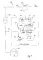
- FIG. 1Ais an illustration of a system configured for measuring current flowing through a power line.
- FIG. 1Bis a schematic of the system of FIG. 1A .
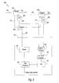
- FIG. 1Cis a block diagram of the system of FIG. 1A , and provides additional detail of the operation of a communications node.
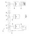
- FIG. 2is a block diagram of a system that employs separate cables for PLC signals and current sense voltage signals.
- FIG. 3is a block diagram of a system that senses a current in a first power line, and also sense a current in a second power line.
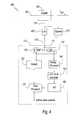
- FIG. 4is a block diagram of another system configured for measuring current flowing through a power line.
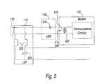
- FIG. 5is a schematic of a portion of a communications node, and shows an exemplary implementation of a high pass filter and a low pass filter.
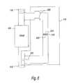
- FIG. 6is a schematic of a portion of the system of FIG. 4 , and shows an exemplary implementation of a bypass module.
- FIG. 7is a block diagram of a system for measuring phase of a current of a medium voltage power line, referenced to a phase of a power voltage.
- FIG. 8is a block diagram of a portion of a power distribution network configured for measuring power parameters at various locations within the power distribution network.
- its secondary circuit outputincludes high frequency PLC signals and a power frequency current sense voltage, which may be separated and separately processed.
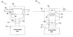
- FIG. 1Ais an illustration, and FIG. 1B is a schematic, of a system 100 configured for measuring current flowing through a power line 103 .
- System 100includes an inductive coupler, i.e., coupler 105 and a communications node 112 .
- Coupler 105includes a magnetic core, i.e., a core 106 , having an aperture 108 therethrough. Coupler 105 operates as a current transformer, and is situated on power line 103 such that power line 103 is routed through aperture 108 and serves as a primary winding, represented schematically in FIG. 1B as a primary winding 102 , for coupler 105 . Coupler 105 also includes a secondary winding 107 . Secondary winding 107 is coupled to communications node 112 via a pair of wires 110 a and 110 b , which are collectively designated as secondary winding pair 110 .
- Power line 103carries (a) a power frequency current, e.g., a current of 200 amperes at a voltage of 13 kV and a frequency of 50-60 Hz, and (b) a PLC signal, also referred to herein as a data signal, e.g., a 10 volt peak-to-peak signal having a frequency in a range of 1 MHz to 50 MHz.
- Coupler 105inductively couples signals between power line 103 and secondary winding pair 110 via core 106 . More particularly, coupler 105 couples the PLC signals bi-directionally between power line 103 and secondary winding pair 110 , and transduces the power frequency current signal from power line 103 into a power frequency voltage across secondary winding pair 110 .
- Power line 103carries a power frequency current, i.e., I 101 , having a frequency f.
- the reactance of power line 103 passing through core 106is less than ten milliohms at power frequency.
- a secondary voltagei.e., a power frequency voltage, is induced across secondary winding 107 .
- a core magnetics' B-H curvestarts as a straight line, from zero current up to some value, e.g. 200 amps, and then its slope starts to decrease, as it enters a region of increasing saturation. “Low current” refers to any current below that “knee.”
- VskXpI 101
- Vs0.9*377 micro-ohms*200 amps
- Vs68 mV.
- Coupler 105by way of its transadmittance, transduces the power line current into a current sense voltage.
- Communications node 112includes modules that sense the current sense voltage Vs. Communications node 112 also includes modules that calculate I 101 , from the current sense voltage Vs, however as an alternative, communications node 112 may transmit data representing the current sense voltage Vs to another piece of equipment that will calculate I 101 .
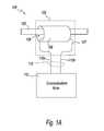
- FIG. 1Cis a block diagram of system 100 .
- Communications node 112includes a filter module 115 , a modem 130 , a data processor 135 , an analog processor 140 , an r.m.s.-to-dc converter 145 , and an analog-to-digital converter (A/D) 150 .
- A/Danalog-to-digital converter
- Filter module 115includes a high pass filter 116 and a low pass filter 117 .
- High pass filter 116passes PLC signals and blocks power frequency voltages.
- Low pass filter 117passes power frequency voltages and blocks PLC signals.
- Low pass filter 117outputs a filtered current sense voltage. The filtered current sense voltage is essentially the same as the current sense voltage Vs.
- Modem 130is coupled to filter module 115 , and more particularly to high pass filter 116 . Modem 130 is also coupled to data processor 135 . Modem 130 conducts bi-directional communication of PLC signals with each of filter module 115 and data processor 135 .
- Analog processor 140receives the filtered current sense voltage from low pass filter 117 .
- Analog processor 140preferably includes a transformer and/or amplifier (not shown), and scales the filtered current sense voltage.
- Analog processor 140outputs a scaled current sense voltage.
- r.m.s.-to-dc converter 145receives the scaled current sense voltage from analog processor 140 .
- the current sense voltage Vsis an approximately sinusoidal voltage.
- the parameter of interestis a root mean square, or an r.m.s. value, of the current.
- r.m.s.-to-dc converter 145converts the scaled current sense voltage to a dc representation of the current sense voltage.
- A/D 150receives the dc representation of the current sense voltage from r.m.s.-to-dc converter 145 , and converts it to a digital output, i.e., current sense data.
- Data processor 135receives the current sense data from A/D 150 , and calculates I 101 . Data processor 135 outputs data that represents a value for I 101 .
- Modem 130receives the data from data processor 135 , modulates the data onto a PLC signal, and transmits the PLC signal via filter module 115 , coupler 105 and power line 103 to a remote monitoring site (not shown in FIG. 1C ).
- the current sense data and or the calculated value of I 101may be output to a data port (not shown) or visual display (not shown) on communications node 112 , to allow service personnel to monitor the line current on-site.
- Coupler 105is an inductive coupler that couples a communication signal from a power line 103 , and transduces the power frequency current into a power frequency voltage.
- filter module 115separates the power frequency voltage from the communications signal, and processor 135 determines a value of a parameter of the power frequency current from the power frequency voltage.
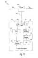
- FIG. 2is a block diagram of a system 200 that employs separate cables for PLC signals and current sense voltage signals.
- System 200includes a low pass filter 205 , and a communications node 212 .
- Communications node 212is similar to communications node 112 , but does not include filter module 115 .
- Secondary wire pair 110from coupler 105 , connects to modem 130 and low pass filter 205 .
- a cable 222connects low pass filter 205 to analog processor 140 .
- Low pass filter 205passes power frequency voltages and blocks PLC signals. Low pass filter 205 receives current sense voltage Vs via secondary pair 110 , and outputs a filtered current sense voltage to cable 222 . Thus, low pass filter 205 separates the current sense voltage Vs from the PLC signals.
- Analog processor 140receives the filtered current sense voltage via cable 222 , and, as in communications node 112 , converts the filtered current sense voltage to a scaled current sense voltage.
- Modem 130 , data processor 135 , r.m.s.-to-dc converter 145 , and A/D 150operate as in communications node 112 .
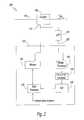
- FIG. 3is a block diagram of a system 300 that senses I 101 in power line 103 , and also senses a current I 301 in a power line 303 .
- System 300includes coupler 105 on power line 103 , and a coupler 305 on power line 303 .
- System 300also includes a signal combiner 320 , a cable 330 , a secondary wire pair 311 , a low pass filter 306 , a cable 323 , and a communications node 312 .
- Coupler 105as in system 100 , (a) couples PLC signals between secondary winding pair 110 and power line 103 , and (b) couples a power signal from power line 103 , and induces a current sense voltage Vs, which is presented across secondary winding pair 110 .
- Coupler 305couples PLC signals between secondary winding pair 311 and power line 303 . Additionally, coupler 305 couples a power signal from power line 303 , and induces a current sense voltage for power line 303 across a secondary winding (not shown) of coupler 305 . The current sense voltage for power line 303 is presented across secondary winding pair 311 .
- Combiner 320couples PLC signals between coupler 105 and communications node 312 , and couples PLC signals between coupler 305 and communications node 312 .
- combiner 320When coupling PLC signals from couplers 105 and 305 to communications node 312 , combiner 320 combines the PLC signals to yield a combined PLC signal, and outputs the combined PLC signal onto cable 330 .
- combiner 320receives a combined PLC signal from communications node 312 , and routes the PLC signals to couplers 105 and 305 .
- couplers 105 and 305are suitable, for example (a) to provide differential coupling onto two phases of the same three phase feeder, so as to cancel electromagnetic emissions, or (b) to couple onto two feeders going off in two directions.
- Modem 130is coupled to combiner 320 , via cable 330 , for bi-directional communication of PLC signals.
- Modem 130 , data processor 135 , r.m.s.-to-dc converter 145 , and analog-to-digital converter 150operate as in communications node 112 .
- Low pass filter 205blocks PLC signals, and passes a current sense voltage from coupler 105 . Low pass filter 205 outputs a filtered current sense voltage corresponding to I 101 .
- Low pass filter 306blocks PLC signals, and passes a current sense voltage from coupler 305 . Low pass filter 306 outputs a filtered current sense voltage corresponding to I 301 .
- Analog processor 340receives the filtered current sense voltage corresponding to I 301 via cable 222 , and receives the filtered current sense voltage corresponding to I 301 via cable 323 .
- Analog processor 340includes an analog multiplexer (not shown) as part of its input circuit, or another appropriate arrangement, for processing multiple input signals.
- FIG. 4is a block diagram of a system 400 that, similarly to system 100 , includes a coupler 105 and a communications node 112 . Communications node 112 operates in system 400 as it does in system 100 .
- system 400includes a circuit 405 , a bypass module 415 , and a cable 410 . Cable 410 connects each of circuit 405 and bypass module 415 to filter module 115 .
- Circuit 405represents circuitry that operates in association with coupler 105 , and passes PLC signals, but blocks power frequency signals. Examples of such circuitry include a surge suppressor and/or an impedance matching transformer.
- bypass module 415provides a path for power frequency signals from coupler 105 to communications node 112 . More particularly, bypass module 415 routes the current sense voltage from coupler 105 , around circuit 405 , to cable 410 .
- the PLC signals from circuit 405 and the current sense voltageare multiplexed onto cable 410 , downstream of circuit 405 .
- Bypass module 415is effectively a low pass filter, and so does not appreciably affect the PLC signals at the inputs or outputs of circuit 405 .
- Filter module 115receives the multiplexed signal via cable 410 , and by operations of high pass filter 116 and low pass filter 117 , demultiplexes the PLC signals and the current sensing voltage.
- FIG. 5is a schematic of a portion of communications node 112 showing an exemplary implementation of high pass filter 116 and low pass filter 117 .
- Modem 130includes a transformer 520 that, in turn, includes a primary winding 515 .
- a secondary of transformer 520is coupled to communications circuitry within modem 130 .
- High pass filter 116includes a capacitor 510 that is situated in series with primary winding 515 .
- Capacitor 510 , primary 515 and modem input impedance Zin 540function together as a high pass filter.
- Low pass filter 117includes chokes 525 and a capacitor 530 . Chokes 525 conduct the current sense voltage signal (i.e., a low frequency signal), and block PLC signals. Capacitor 530 filters out any residual high frequency component.
- FIG. 6is a schematic of a portion of system 400 , and shows an exemplary implementation of bypass module 415 .
- bypass module 415is shown to include chokes 605 , a transformer 615 , and a capacitor 625 .
- circuit 405passes PLC signals, but blocks power frequency signals.
- Chokes 605provide a low impedance path for the current sense voltage signal (from secondary winding pair 110 ) to a primary 610 of transformer 615 .
- Transformer 615is a low frequency transformer, and may have a non-unity turns ratio so as to scale the magnitude of the current sense voltage to match an input voltage range of analog-to-digital converter 140 or r.m.s.-to-dc converter 145 (see FIG. 1C ).
- a secondary 620 of transformer 615is connected in series with a wire that conducts PLC signals at the output of circuit 405 .
- Capacitor 625has a value in the range of nanofarads, and acts as a short circuit to conduct the (high frequency) PLC signals, while appearing as an open circuit to the (low frequency) current sense voltage. Accordingly, for low frequencies, secondary 620 is placed in series with the output of circuit 405 .
- FIG. 7is a block diagram of a system 700 for measuring phase of a current of a medium voltage power line, referenced to a phase of a power voltage.
- System 700includes coupler 105 , a distribution transformer 702 , and a communications node 712 .
- Distribution transformer 702transforms voltage from power line 103 to a lower voltage, and provides power to loads in a premises 740 . Additionally, distribution transformer 702 provides power to communications node 712 via a low voltage power line 725 .
- Communications node 712includes filter module 115 , modem 130 , analog processor 140 , r.m.s.-to-dc converter 145 , and data processor 135 , all of which operate as described above. Communications node 712 further includes, a phase detector 730 , and an analog-to-digital converter 750 .
- Phase detector 730determines the phase of I 101 , relative to a reference phase. More specifically, phase detector 730 receives a reference voltage derived from low voltage power line 725 , and also receives an amplified current sense voltage from the output of analog processor 140 . Phase detector 730 determines the phase of I 101 , based on a phase relationship between the reference voltage derived from low voltage power line 725 , and the amplified current sense voltage from the output of analog processor 140 . Phase detector 730 outputs a voltage that represents the phase of I 101 relative to the phase of the reference voltage derived from low voltage power line 725 .
- Analog-to-digital converter 750has two inputs, namely (a) an input from phase detector 730 , i.e., the voltage that represents the phase of I 101 , and (b) an input from r.m.s.-to-dc converter 145 , i.e., the dc representation of the current sense voltage. Analog-to-digital converter 750 converts each of the two inputs to digital format, and outputs phase data and current sense data.
- Data processor 235receives the phase data and the current sense data from analog-to-digital converter 750 , and sends the phase data and the current sense data to modem 130 .
- Modem 130modulates the phase data and the current sense data onto PLC signal, and transmits the PLC signal via filter module 115 , coupler 105 and power line 103 , to other communications nodes (not shown in FIG. 7 ) connected by other couplers (not shown in FIG. 7 ) on a power line grid of which power line 103 is a part.
- this informationmay be presented on a display or at a data port (neither of which is shown) installed on or adjacent to communications node 712 , for the benefit of personnel providing service at a site at which communications node 712 is located.
- FIG. 8is a block diagram of a portion of a power distribution network 800 configured for measuring power parameters at various locations within power distribution network 800 .
- Power distribution network 800includes a three phase medium voltage power line, i.e., power line 825 , couplers 805 , 815 and 830 , communications nodes 840 , 845 and 850 , and a monitor system 855 .
- Couplers 805 , 815 and 830are each similar to coupler 105 .
- Communications nodes 840 , 845 and 850are each similar to communications node 712 .
- Coupler 805is situated at a location 810 , and coupled to communications node 840 .
- Coupler 815is situated at a location 820 , and coupled to communications node 845 .
- Coupler 830is situated at a location 835 , and coupled to communications node 850 .
- Monitor system 855is also coupled to communications node 850 .
- a distribution transformer 837transforms voltage from a phase line of power line 825 to a lower voltage, and provides power to loads in a premises 852 . Additionally, distribution transformer 837 provides power to communications node 840 . Communications nodes 845 and 850 are similarly powered by other distribution transformers (not shown).
- Coupler 805 and communications node 840operate together to sense current, phase and voltage at location 810 .
- Communications node 840periodically transmits the sensed values for location 810 , in a PLC signal, via coupler 805 , power line 825 , coupler 830 and communications node 850 to monitor system 855 .
- Coupler 815 and communications node 845operate together to sense current, phase and voltage at location 820 .
- Communications node 845periodically transmits the sensed values for location 820 , in a PLC signal, via coupler 815 , power line 825 , coupler 830 and communications node 850 to monitor system 855 .
- Coupler 830 and communications node 850operate together to sense current, phase and voltage at location 835 .
- Communications node 850periodically reports the sensed values for location 835 to monitor system 855 .
- Monitor system 855is at a central control location, e.g. a substation. Monitor system 855 receives the sensed data for each of locations 810 , 820 and 835 , and develops a system-wide picture of currents and other electrical parameters throughout power distribution network 800 . Monitor system 855 includes a display, analysis equipment, recording equipment and an alarm system that allows utility personnel to monitor operation of power distribution system 800 , quickly locate and eliminate power outages when they occur, thus improving reliability and lowering the overall cost of grid maintenance of power distribution system 800 .
- coupler 805is attached to a lower phase line of power line 825
- coupler 830is attached to a middle phase line of power line 825 .
- PLC signalscouple from one phase to another, allowing communications relatively independent of the phase line on which a coupler is situated.
- sensingis described herein as sensing parameters on the phase lines to which couplers are attached, it is possible to attach self-contained conventional current sensors (not shown) to other phases, attach the digital outputs of the current sensors to ports (not shown) on communications nodes such as communications node 840 , and provide monitor system 855 with a more complete set of data.
- self-contained, conventional voltage sensorsmay be attached to low voltage or medium voltage power lines, and their digital data also supplied to monitor system 855 .
- the utility companycan attach the types of sensors that the utility company typically uses to the other lines (otherwise unsensed by communications nodes 840 , 845 and 850 ), and a conveniently situated communications node 840 , 845 or 850 can serve as a digital data relay for these extra data sources.
- system 100there may not be a PLC signal present on power line 103 at a time when communications node 112 is measuring I 101 .
- the signal being coupled from power line 103 , via coupler 105may include only the power frequency signal, and no PLC signal.
- communications node 112need not be configured for bi-directional communication, but instead, may be configured only for PLC transmission via coupler 105 .
- communications node 112would sense the power frequency signal, and thereafter transmit data representing the sensed signal, in a PLC signal, via coupler 105 , to a remote monitoring station. Furthermore, communications node 112 need not be configured for any PLC via coupler 105 . For example, communications node 112 may sense, process and present a result via an interface local to communications node 112 , without necessarily transmitting any data to any other device.
- the systems described hereininclude an inductive coupler that can provide both current measurement and communications, so the measured data is easily concentrated at a central point, for analysis, alarm, recording and fault detection.
- high pass filter 116low pass filter 117 and bypass module 415 are described herein as being implemented with discrete components (i.e., discrete capacitors and discrete inductors), they may be implemented as digital circuits in which their respective operations are preformed by digital signal processing.
- discrete componentsi.e., discrete capacitors and discrete inductors
Landscapes
- Physics & Mathematics (AREA)
- General Physics & Mathematics (AREA)
- Cable Transmission Systems, Equalization Of Radio And Reduction Of Echo (AREA)
Abstract
Description
Xp=2πfLp.
Xp=2πfLp=1.13 milliohms.
Vp=XpI101.
A secondary voltage, i.e., a power frequency voltage, is induced across
Vs=kVp,
where k is a coupling coefficient for
I101=Vp/Xp=Vs/(k Xp).
Defining transadmittance as
Y=1/(k Xp),
I101may be calculated as
I101=YVs.
I101=YVs.
Xp=2πfLp
Xp=(2π)(60)(1 μH)
Xp=377 micro-ohms
and
Y=1/(k Xp)
Y=1/(0.9(377 micro-ohms))
Y=2950 mhos.
Vs=kXpI101
Vs=0.9*377 micro-ohms*200 amps
Vs=68 mV.
Claims (14)
Priority Applications (10)
| Application Number | Priority Date | Filing Date | Title |
|---|---|---|---|
| US11/482,275US8093745B2 (en) | 2006-07-07 | 2006-07-07 | Sensing current flowing through a power line |
| KR1020097000240AKR101291410B1 (en) | 2006-07-07 | 2007-04-10 | Sensing current flowing through a power line |
| CN2007800258331ACN101573737B (en) | 2006-07-07 | 2007-04-10 | Systems and methods for sensing parameters of current flowing through power lines |
| EP07755231.3AEP2044581A4 (en) | 2006-07-07 | 2007-04-10 | Sensing current flowing through a power line |
| EA200802377AEA013000B1 (en) | 2006-07-07 | 2007-04-10 | Measuring a parameter of a current flowing through a power line |
| BRPI0713855-5A2ABRPI0713855A2 (en) | 2006-07-07 | 2007-04-10 | CURRENT FLOW SENSOR THROUGH A POWER LINE |
| CA2656152ACA2656152C (en) | 2006-07-07 | 2007-04-10 | Sensing current flowing through a power line |
| MX2008015823AMX2008015823A (en) | 2006-07-07 | 2007-04-10 | Sensing current flowing through a power line. |
| PCT/US2007/008895WO2008008106A2 (en) | 2006-07-07 | 2007-04-10 | Sensing current flowing through a power line |
| AU2007273232AAU2007273232B2 (en) | 2006-07-07 | 2007-04-10 | Sensing current flowing through a power line |
Applications Claiming Priority (1)
| Application Number | Priority Date | Filing Date | Title |
|---|---|---|---|
| US11/482,275US8093745B2 (en) | 2006-07-07 | 2006-07-07 | Sensing current flowing through a power line |
Publications (2)
| Publication Number | Publication Date |
|---|---|
| US20080007416A1 US20080007416A1 (en) | 2008-01-10 |
| US8093745B2true US8093745B2 (en) | 2012-01-10 |
Family
ID=38918653
Family Applications (1)
| Application Number | Title | Priority Date | Filing Date |
|---|---|---|---|
| US11/482,275Expired - Fee RelatedUS8093745B2 (en) | 2006-07-07 | 2006-07-07 | Sensing current flowing through a power line |
Country Status (10)
| Country | Link |
|---|---|
| US (1) | US8093745B2 (en) |
| EP (1) | EP2044581A4 (en) |
| KR (1) | KR101291410B1 (en) |
| CN (1) | CN101573737B (en) |
| AU (1) | AU2007273232B2 (en) |
| BR (1) | BRPI0713855A2 (en) |
| CA (1) | CA2656152C (en) |
| EA (1) | EA013000B1 (en) |
| MX (1) | MX2008015823A (en) |
| WO (1) | WO2008008106A2 (en) |
Cited By (5)
| Publication number | Priority date | Publication date | Assignee | Title |
|---|---|---|---|---|
| US20140312840A1 (en)* | 2011-09-09 | 2014-10-23 | Sumitomo Electric Industries, Ltd. | Power supply system and connector |
| US20150028801A1 (en)* | 2013-07-23 | 2015-01-29 | Qualcomm Incorporated | Systems and methods for extending the power capability of a wireless charger |
| US9490653B2 (en) | 2013-07-23 | 2016-11-08 | Qualcomm Incorporated | Systems and methods for enabling a universal back-cover wireless charging solution |
| US20170106759A1 (en)* | 2014-05-07 | 2017-04-20 | Equos Research Co., Ltd. | Power transmission system |
| US20210359550A1 (en)* | 2018-09-06 | 2021-11-18 | Auckland Uniservices Limited | Inductive power and data transfer using energy injection |
Families Citing this family (200)
| Publication number | Priority date | Publication date | Assignee | Title |
|---|---|---|---|---|
| US6998962B2 (en)* | 2000-04-14 | 2006-02-14 | Current Technologies, Llc | Power line communication apparatus and method of using the same |
| EP1892843B1 (en)* | 2006-08-24 | 2014-10-01 | Sony Deutschland GmbH | Method for transmitting a signal on a power line network, transmitting unit, receiving unit and system |
| US7795877B2 (en) | 2006-11-02 | 2010-09-14 | Current Technologies, Llc | Power line communication and power distribution parameter measurement system and method |
| US7795994B2 (en)* | 2007-06-26 | 2010-09-14 | Current Technologies, Llc | Power line coupling device and method |
| US7876174B2 (en)* | 2007-06-26 | 2011-01-25 | Current Technologies, Llc | Power line coupling device and method |
| US20090085726A1 (en)* | 2007-09-27 | 2009-04-02 | Radtke William O | Power Line Communications Coupling Device and Method |
| US20090289637A1 (en)* | 2007-11-07 | 2009-11-26 | Radtke William O | System and Method for Determining the Impedance of a Medium Voltage Power Line |
| US7714592B2 (en)* | 2007-11-07 | 2010-05-11 | Current Technologies, Llc | System and method for determining the impedance of a medium voltage power line |
| US8077049B2 (en)* | 2008-01-20 | 2011-12-13 | Current Technologies, Llc | Method and apparatus for communicating power distribution event and location |
| US8566046B2 (en)* | 2008-01-21 | 2013-10-22 | Current Technologies, Llc | System, device and method for determining power line equipment degradation |
| US8666685B2 (en) | 2011-04-19 | 2014-03-04 | Schneider Electronic IT Corporation | System of intelligent sensors in an electrical panelboard |
| US9146259B2 (en)* | 2011-04-19 | 2015-09-29 | Schneider Electric It Corporation | Smart current transformers |
| US8660810B2 (en) | 2011-04-19 | 2014-02-25 | Schneider Electric It Corporation | System and method to calculate RMS current and true power in a multidrop sensor network |
| CN102227090B (en)* | 2011-06-27 | 2013-08-21 | 山西省电力公司临汾供电分公司 | Intelligent FA (feeder automation) system of 10kV-carrier communication |
| DE102011083307A1 (en)* | 2011-09-23 | 2013-03-28 | Continental Automotive Gmbh | Device for measuring a battery current |
| AU2012322015A1 (en)* | 2011-10-12 | 2014-05-15 | Cequent Performance Products, Inc. | Current sensing electrical converter |
| EP2836848B1 (en) | 2012-04-12 | 2020-04-01 | Schneider Electric IT Corporation | System and method for detecting branch circuit current |
| EP2841954B1 (en) | 2012-04-25 | 2022-03-02 | Schneider Electric IT Corporation | Current monitoring device |
| US9113347B2 (en) | 2012-12-05 | 2015-08-18 | At&T Intellectual Property I, Lp | Backhaul link for distributed antenna system |
| US10009065B2 (en) | 2012-12-05 | 2018-06-26 | At&T Intellectual Property I, L.P. | Backhaul link for distributed antenna system |
| GB2508843A (en)* | 2012-12-12 | 2014-06-18 | Univ Manchester | A current transformer for measuring current in a conductor |
| ES2743697T3 (en) | 2012-12-27 | 2020-02-20 | Schneider Electric Usa Inc | Power meter with current and phase sensor |
| US9999038B2 (en) | 2013-05-31 | 2018-06-12 | At&T Intellectual Property I, L.P. | Remote distributed antenna system |
| US9525524B2 (en) | 2013-05-31 | 2016-12-20 | At&T Intellectual Property I, L.P. | Remote distributed antenna system |
| US9689910B2 (en)* | 2013-06-10 | 2017-06-27 | Wabtec Holding Corp. | Detecting faults in a two-wire power line |
| US8897697B1 (en) | 2013-11-06 | 2014-11-25 | At&T Intellectual Property I, Lp | Millimeter-wave surface-wave communications |
| US9209902B2 (en) | 2013-12-10 | 2015-12-08 | At&T Intellectual Property I, L.P. | Quasi-optical coupler |
| US9973036B2 (en) | 2013-12-31 | 2018-05-15 | Schneider Electric It Corporation | Automatic sub-millisecond clock synchronization |
| US9692101B2 (en) | 2014-08-26 | 2017-06-27 | At&T Intellectual Property I, L.P. | Guided wave couplers for coupling electromagnetic waves between a waveguide surface and a surface of a wire |
| US9768833B2 (en) | 2014-09-15 | 2017-09-19 | At&T Intellectual Property I, L.P. | Method and apparatus for sensing a condition in a transmission medium of electromagnetic waves |
| US10063280B2 (en) | 2014-09-17 | 2018-08-28 | At&T Intellectual Property I, L.P. | Monitoring and mitigating conditions in a communication network |
| US9628854B2 (en) | 2014-09-29 | 2017-04-18 | At&T Intellectual Property I, L.P. | Method and apparatus for distributing content in a communication network |
| US9615269B2 (en) | 2014-10-02 | 2017-04-04 | At&T Intellectual Property I, L.P. | Method and apparatus that provides fault tolerance in a communication network |
| US9685992B2 (en) | 2014-10-03 | 2017-06-20 | At&T Intellectual Property I, L.P. | Circuit panel network and methods thereof |
| US9503189B2 (en) | 2014-10-10 | 2016-11-22 | At&T Intellectual Property I, L.P. | Method and apparatus for arranging communication sessions in a communication system |
| US9973299B2 (en) | 2014-10-14 | 2018-05-15 | At&T Intellectual Property I, L.P. | Method and apparatus for adjusting a mode of communication in a communication network |
| US9762289B2 (en) | 2014-10-14 | 2017-09-12 | At&T Intellectual Property I, L.P. | Method and apparatus for transmitting or receiving signals in a transportation system |
| US9653770B2 (en) | 2014-10-21 | 2017-05-16 | At&T Intellectual Property I, L.P. | Guided wave coupler, coupling module and methods for use therewith |
| US9312919B1 (en) | 2014-10-21 | 2016-04-12 | At&T Intellectual Property I, Lp | Transmission device with impairment compensation and methods for use therewith |
| US9577306B2 (en) | 2014-10-21 | 2017-02-21 | At&T Intellectual Property I, L.P. | Guided-wave transmission device and methods for use therewith |
| US9769020B2 (en) | 2014-10-21 | 2017-09-19 | At&T Intellectual Property I, L.P. | Method and apparatus for responding to events affecting communications in a communication network |
| US9564947B2 (en) | 2014-10-21 | 2017-02-07 | At&T Intellectual Property I, L.P. | Guided-wave transmission device with diversity and methods for use therewith |
| US9627768B2 (en) | 2014-10-21 | 2017-04-18 | At&T Intellectual Property I, L.P. | Guided-wave transmission device with non-fundamental mode propagation and methods for use therewith |
| US9520945B2 (en) | 2014-10-21 | 2016-12-13 | At&T Intellectual Property I, L.P. | Apparatus for providing communication services and methods thereof |
| US9780834B2 (en) | 2014-10-21 | 2017-10-03 | At&T Intellectual Property I, L.P. | Method and apparatus for transmitting electromagnetic waves |
| US10516555B2 (en) | 2014-11-20 | 2019-12-24 | At&T Intellectual Property I, L.P. | Methods and apparatus for creating interstitial areas in a cable |
| US9461706B1 (en) | 2015-07-31 | 2016-10-04 | At&T Intellectual Property I, Lp | Method and apparatus for exchanging communication signals |
| US10340573B2 (en) | 2016-10-26 | 2019-07-02 | At&T Intellectual Property I, L.P. | Launcher with cylindrical coupling device and methods for use therewith |
| US10009067B2 (en) | 2014-12-04 | 2018-06-26 | At&T Intellectual Property I, L.P. | Method and apparatus for configuring a communication interface |
| US11025460B2 (en) | 2014-11-20 | 2021-06-01 | At&T Intellectual Property I, L.P. | Methods and apparatus for accessing interstitial areas of a cable |
| US10411920B2 (en) | 2014-11-20 | 2019-09-10 | At&T Intellectual Property I, L.P. | Methods and apparatus for inducing electromagnetic waves within pathways of a cable |
| US10505250B2 (en) | 2014-11-20 | 2019-12-10 | At&T Intellectual Property I, L.P. | Communication system having a cable with a plurality of stranded uninsulated conductors forming interstitial areas for propagating guided wave modes therein and methods of use |
| US9680670B2 (en) | 2014-11-20 | 2017-06-13 | At&T Intellectual Property I, L.P. | Transmission device with channel equalization and control and methods for use therewith |
| US9954287B2 (en) | 2014-11-20 | 2018-04-24 | At&T Intellectual Property I, L.P. | Apparatus for converting wireless signals and electromagnetic waves and methods thereof |
| US10243784B2 (en) | 2014-11-20 | 2019-03-26 | At&T Intellectual Property I, L.P. | System for generating topology information and methods thereof |
| US10505252B2 (en) | 2014-11-20 | 2019-12-10 | At&T Intellectual Property I, L.P. | Communication system having a coupler for guiding electromagnetic waves through interstitial areas formed by a plurality of stranded uninsulated conductors and method of use |
| US9997819B2 (en) | 2015-06-09 | 2018-06-12 | At&T Intellectual Property I, L.P. | Transmission medium and method for facilitating propagation of electromagnetic waves via a core |
| US10554454B2 (en) | 2014-11-20 | 2020-02-04 | At&T Intellectual Property I, L.P. | Methods and apparatus for inducing electromagnetic waves in a cable |
| US9800327B2 (en) | 2014-11-20 | 2017-10-24 | At&T Intellectual Property I, L.P. | Apparatus for controlling operations of a communication device and methods thereof |
| US10505249B2 (en) | 2014-11-20 | 2019-12-10 | At&T Intellectual Property I, L.P. | Communication system having a cable with a plurality of stranded uninsulated conductors forming interstitial areas for guiding electromagnetic waves therein and method of use |
| US9654173B2 (en) | 2014-11-20 | 2017-05-16 | At&T Intellectual Property I, L.P. | Apparatus for powering a communication device and methods thereof |
| US9544006B2 (en) | 2014-11-20 | 2017-01-10 | At&T Intellectual Property I, L.P. | Transmission device with mode division multiplexing and methods for use therewith |
| US9742462B2 (en) | 2014-12-04 | 2017-08-22 | At&T Intellectual Property I, L.P. | Transmission medium and communication interfaces and methods for use therewith |
| US10505248B2 (en) | 2014-11-20 | 2019-12-10 | At&T Intellectual Property I, L.P. | Communication cable having a plurality of uninsulated conductors forming interstitial areas for propagating electromagnetic waves therein and method of use |
| US10144036B2 (en) | 2015-01-30 | 2018-12-04 | At&T Intellectual Property I, L.P. | Method and apparatus for mitigating interference affecting a propagation of electromagnetic waves guided by a transmission medium |
| CN104779975A (en)* | 2015-02-14 | 2015-07-15 | 云南电网有限责任公司 | A differential coupling communication device of high speed power line carrier system |
| US9876570B2 (en) | 2015-02-20 | 2018-01-23 | At&T Intellectual Property I, Lp | Guided-wave transmission device with non-fundamental mode propagation and methods for use therewith |
| US9749013B2 (en) | 2015-03-17 | 2017-08-29 | At&T Intellectual Property I, L.P. | Method and apparatus for reducing attenuation of electromagnetic waves guided by a transmission medium |
| US10224981B2 (en) | 2015-04-24 | 2019-03-05 | At&T Intellectual Property I, Lp | Passive electrical coupling device and methods for use therewith |
| US9705561B2 (en) | 2015-04-24 | 2017-07-11 | At&T Intellectual Property I, L.P. | Directional coupling device and methods for use therewith |
| US9793954B2 (en) | 2015-04-28 | 2017-10-17 | At&T Intellectual Property I, L.P. | Magnetic coupling device and methods for use therewith |
| US9948354B2 (en) | 2015-04-28 | 2018-04-17 | At&T Intellectual Property I, L.P. | Magnetic coupling device with reflective plate and methods for use therewith |
| US9748626B2 (en) | 2015-05-14 | 2017-08-29 | At&T Intellectual Property I, L.P. | Plurality of cables having different cross-sectional shapes which are bundled together to form a transmission medium |
| US9490869B1 (en) | 2015-05-14 | 2016-11-08 | At&T Intellectual Property I, L.P. | Transmission medium having multiple cores and methods for use therewith |
| US9871282B2 (en) | 2015-05-14 | 2018-01-16 | At&T Intellectual Property I, L.P. | At least one transmission medium having a dielectric surface that is covered at least in part by a second dielectric |
| US10650940B2 (en) | 2015-05-15 | 2020-05-12 | At&T Intellectual Property I, L.P. | Transmission medium having a conductive material and methods for use therewith |
| US10679767B2 (en) | 2015-05-15 | 2020-06-09 | At&T Intellectual Property I, L.P. | Transmission medium having a conductive material and methods for use therewith |
| US9917341B2 (en) | 2015-05-27 | 2018-03-13 | At&T Intellectual Property I, L.P. | Apparatus and method for launching electromagnetic waves and for modifying radial dimensions of the propagating electromagnetic waves |
| US10103801B2 (en) | 2015-06-03 | 2018-10-16 | At&T Intellectual Property I, L.P. | Host node device and methods for use therewith |
| US10812174B2 (en) | 2015-06-03 | 2020-10-20 | At&T Intellectual Property I, L.P. | Client node device and methods for use therewith |
| US10348391B2 (en) | 2015-06-03 | 2019-07-09 | At&T Intellectual Property I, L.P. | Client node device with frequency conversion and methods for use therewith |
| US10154493B2 (en) | 2015-06-03 | 2018-12-11 | At&T Intellectual Property I, L.P. | Network termination and methods for use therewith |
| US9866309B2 (en) | 2015-06-03 | 2018-01-09 | At&T Intellectual Property I, Lp | Host node device and methods for use therewith |
| US9912381B2 (en) | 2015-06-03 | 2018-03-06 | At&T Intellectual Property I, Lp | Network termination and methods for use therewith |
| US9913139B2 (en) | 2015-06-09 | 2018-03-06 | At&T Intellectual Property I, L.P. | Signal fingerprinting for authentication of communicating devices |
| US9608692B2 (en) | 2015-06-11 | 2017-03-28 | At&T Intellectual Property I, L.P. | Repeater and methods for use therewith |
| US10142086B2 (en) | 2015-06-11 | 2018-11-27 | At&T Intellectual Property I, L.P. | Repeater and methods for use therewith |
| US9820146B2 (en) | 2015-06-12 | 2017-11-14 | At&T Intellectual Property I, L.P. | Method and apparatus for authentication and identity management of communicating devices |
| US9667317B2 (en) | 2015-06-15 | 2017-05-30 | At&T Intellectual Property I, L.P. | Method and apparatus for providing security using network traffic adjustments |
| US9509415B1 (en) | 2015-06-25 | 2016-11-29 | At&T Intellectual Property I, L.P. | Methods and apparatus for inducing a fundamental wave mode on a transmission medium |
| US9865911B2 (en) | 2015-06-25 | 2018-01-09 | At&T Intellectual Property I, L.P. | Waveguide system for slot radiating first electromagnetic waves that are combined into a non-fundamental wave mode second electromagnetic wave on a transmission medium |
| US9640850B2 (en) | 2015-06-25 | 2017-05-02 | At&T Intellectual Property I, L.P. | Methods and apparatus for inducing a non-fundamental wave mode on a transmission medium |
| US9853342B2 (en) | 2015-07-14 | 2017-12-26 | At&T Intellectual Property I, L.P. | Dielectric transmission medium connector and methods for use therewith |
| US10320586B2 (en) | 2015-07-14 | 2019-06-11 | At&T Intellectual Property I, L.P. | Apparatus and methods for generating non-interfering electromagnetic waves on an insulated transmission medium |
| US10170840B2 (en) | 2015-07-14 | 2019-01-01 | At&T Intellectual Property I, L.P. | Apparatus and methods for sending or receiving electromagnetic signals |
| US10341142B2 (en) | 2015-07-14 | 2019-07-02 | At&T Intellectual Property I, L.P. | Apparatus and methods for generating non-interfering electromagnetic waves on an uninsulated conductor |
| US9722318B2 (en) | 2015-07-14 | 2017-08-01 | At&T Intellectual Property I, L.P. | Method and apparatus for coupling an antenna to a device |
| US10033108B2 (en) | 2015-07-14 | 2018-07-24 | At&T Intellectual Property I, L.P. | Apparatus and methods for generating an electromagnetic wave having a wave mode that mitigates interference |
| US10148016B2 (en) | 2015-07-14 | 2018-12-04 | At&T Intellectual Property I, L.P. | Apparatus and methods for communicating utilizing an antenna array |
| US10044409B2 (en) | 2015-07-14 | 2018-08-07 | At&T Intellectual Property I, L.P. | Transmission medium and methods for use therewith |
| US9628116B2 (en) | 2015-07-14 | 2017-04-18 | At&T Intellectual Property I, L.P. | Apparatus and methods for transmitting wireless signals |
| US10205655B2 (en) | 2015-07-14 | 2019-02-12 | At&T Intellectual Property I, L.P. | Apparatus and methods for communicating utilizing an antenna array and multiple communication paths |
| US10033107B2 (en) | 2015-07-14 | 2018-07-24 | At&T Intellectual Property I, L.P. | Method and apparatus for coupling an antenna to a device |
| US9882257B2 (en) | 2015-07-14 | 2018-01-30 | At&T Intellectual Property I, L.P. | Method and apparatus for launching a wave mode that mitigates interference |
| US9847566B2 (en) | 2015-07-14 | 2017-12-19 | At&T Intellectual Property I, L.P. | Method and apparatus for adjusting a field of a signal to mitigate interference |
| US9836957B2 (en) | 2015-07-14 | 2017-12-05 | At&T Intellectual Property I, L.P. | Method and apparatus for communicating with premises equipment |
| US9608740B2 (en) | 2015-07-15 | 2017-03-28 | At&T Intellectual Property I, L.P. | Method and apparatus for launching a wave mode that mitigates interference |
| US9793951B2 (en) | 2015-07-15 | 2017-10-17 | At&T Intellectual Property I, L.P. | Method and apparatus for launching a wave mode that mitigates interference |
| US10090606B2 (en) | 2015-07-15 | 2018-10-02 | At&T Intellectual Property I, L.P. | Antenna system with dielectric array and methods for use therewith |
| US9871283B2 (en) | 2015-07-23 | 2018-01-16 | At&T Intellectual Property I, Lp | Transmission medium having a dielectric core comprised of plural members connected by a ball and socket configuration |
| US9749053B2 (en) | 2015-07-23 | 2017-08-29 | At&T Intellectual Property I, L.P. | Node device, repeater and methods for use therewith |
| US10784670B2 (en) | 2015-07-23 | 2020-09-22 | At&T Intellectual Property I, L.P. | Antenna support for aligning an antenna |
| US9948333B2 (en) | 2015-07-23 | 2018-04-17 | At&T Intellectual Property I, L.P. | Method and apparatus for wireless communications to mitigate interference |
| US9912027B2 (en) | 2015-07-23 | 2018-03-06 | At&T Intellectual Property I, L.P. | Method and apparatus for exchanging communication signals |
| US9967173B2 (en) | 2015-07-31 | 2018-05-08 | At&T Intellectual Property I, L.P. | Method and apparatus for authentication and identity management of communicating devices |
| US10020587B2 (en) | 2015-07-31 | 2018-07-10 | At&T Intellectual Property I, L.P. | Radial antenna and methods for use therewith |
| US9735833B2 (en) | 2015-07-31 | 2017-08-15 | At&T Intellectual Property I, L.P. | Method and apparatus for communications management in a neighborhood network |
| US9904535B2 (en) | 2015-09-14 | 2018-02-27 | At&T Intellectual Property I, L.P. | Method and apparatus for distributing software |
| US10009063B2 (en) | 2015-09-16 | 2018-06-26 | At&T Intellectual Property I, L.P. | Method and apparatus for use with a radio distributed antenna system having an out-of-band reference signal |
| US10051629B2 (en) | 2015-09-16 | 2018-08-14 | At&T Intellectual Property I, L.P. | Method and apparatus for use with a radio distributed antenna system having an in-band reference signal |
| US9705571B2 (en) | 2015-09-16 | 2017-07-11 | At&T Intellectual Property I, L.P. | Method and apparatus for use with a radio distributed antenna system |
| US10009901B2 (en) | 2015-09-16 | 2018-06-26 | At&T Intellectual Property I, L.P. | Method, apparatus, and computer-readable storage medium for managing utilization of wireless resources between base stations |
| US10079661B2 (en) | 2015-09-16 | 2018-09-18 | At&T Intellectual Property I, L.P. | Method and apparatus for use with a radio distributed antenna system having a clock reference |
| US10136434B2 (en) | 2015-09-16 | 2018-11-20 | At&T Intellectual Property I, L.P. | Method and apparatus for use with a radio distributed antenna system having an ultra-wideband control channel |
| US9769128B2 (en) | 2015-09-28 | 2017-09-19 | At&T Intellectual Property I, L.P. | Method and apparatus for encryption of communications over a network |
| US9729197B2 (en) | 2015-10-01 | 2017-08-08 | At&T Intellectual Property I, L.P. | Method and apparatus for communicating network management traffic over a network |
| US9876264B2 (en) | 2015-10-02 | 2018-01-23 | At&T Intellectual Property I, Lp | Communication system, guided wave switch and methods for use therewith |
| US9882277B2 (en) | 2015-10-02 | 2018-01-30 | At&T Intellectual Property I, Lp | Communication device and antenna assembly with actuated gimbal mount |
| US10074890B2 (en) | 2015-10-02 | 2018-09-11 | At&T Intellectual Property I, L.P. | Communication device and antenna with integrated light assembly |
| CN105322982A (en)* | 2015-10-08 | 2016-02-10 | 云南电网有限责任公司电力科学研究院 | Differential coupled communication method applied to high-speed power line carrier (H-PLC) system |
| US10665942B2 (en) | 2015-10-16 | 2020-05-26 | At&T Intellectual Property I, L.P. | Method and apparatus for adjusting wireless communications |
| US10355367B2 (en) | 2015-10-16 | 2019-07-16 | At&T Intellectual Property I, L.P. | Antenna structure for exchanging wireless signals |
| US10051483B2 (en) | 2015-10-16 | 2018-08-14 | At&T Intellectual Property I, L.P. | Method and apparatus for directing wireless signals |
| US9912419B1 (en) | 2016-08-24 | 2018-03-06 | At&T Intellectual Property I, L.P. | Method and apparatus for managing a fault in a distributed antenna system |
| US9860075B1 (en) | 2016-08-26 | 2018-01-02 | At&T Intellectual Property I, L.P. | Method and communication node for broadband distribution |
| US10291311B2 (en) | 2016-09-09 | 2019-05-14 | At&T Intellectual Property I, L.P. | Method and apparatus for mitigating a fault in a distributed antenna system |
| US11032819B2 (en) | 2016-09-15 | 2021-06-08 | At&T Intellectual Property I, L.P. | Method and apparatus for use with a radio distributed antenna system having a control channel reference signal |
| US10135147B2 (en) | 2016-10-18 | 2018-11-20 | At&T Intellectual Property I, L.P. | Apparatus and methods for launching guided waves via an antenna |
| US10340600B2 (en) | 2016-10-18 | 2019-07-02 | At&T Intellectual Property I, L.P. | Apparatus and methods for launching guided waves via plural waveguide systems |
| US10135146B2 (en) | 2016-10-18 | 2018-11-20 | At&T Intellectual Property I, L.P. | Apparatus and methods for launching guided waves via circuits |
| US10811767B2 (en) | 2016-10-21 | 2020-10-20 | At&T Intellectual Property I, L.P. | System and dielectric antenna with convex dielectric radome |
| US9876605B1 (en) | 2016-10-21 | 2018-01-23 | At&T Intellectual Property I, L.P. | Launcher and coupling system to support desired guided wave mode |
| US10374316B2 (en) | 2016-10-21 | 2019-08-06 | At&T Intellectual Property I, L.P. | System and dielectric antenna with non-uniform dielectric |
| US9991580B2 (en) | 2016-10-21 | 2018-06-05 | At&T Intellectual Property I, L.P. | Launcher and coupling system for guided wave mode cancellation |
| US10312567B2 (en) | 2016-10-26 | 2019-06-04 | At&T Intellectual Property I, L.P. | Launcher with planar strip antenna and methods for use therewith |
| US10225025B2 (en) | 2016-11-03 | 2019-03-05 | At&T Intellectual Property I, L.P. | Method and apparatus for detecting a fault in a communication system |
| US10498044B2 (en) | 2016-11-03 | 2019-12-03 | At&T Intellectual Property I, L.P. | Apparatus for configuring a surface of an antenna |
| US10224634B2 (en) | 2016-11-03 | 2019-03-05 | At&T Intellectual Property I, L.P. | Methods and apparatus for adjusting an operational characteristic of an antenna |
| US10291334B2 (en) | 2016-11-03 | 2019-05-14 | At&T Intellectual Property I, L.P. | System for detecting a fault in a communication system |
| US10535928B2 (en) | 2016-11-23 | 2020-01-14 | At&T Intellectual Property I, L.P. | Antenna system and methods for use therewith |
| US10178445B2 (en) | 2016-11-23 | 2019-01-08 | At&T Intellectual Property I, L.P. | Methods, devices, and systems for load balancing between a plurality of waveguides |
| US10340603B2 (en) | 2016-11-23 | 2019-07-02 | At&T Intellectual Property I, L.P. | Antenna system having shielded structural configurations for assembly |
| US10090594B2 (en) | 2016-11-23 | 2018-10-02 | At&T Intellectual Property I, L.P. | Antenna system having structural configurations for assembly |
| US10340601B2 (en) | 2016-11-23 | 2019-07-02 | At&T Intellectual Property I, L.P. | Multi-antenna system and methods for use therewith |
| US10361489B2 (en) | 2016-12-01 | 2019-07-23 | At&T Intellectual Property I, L.P. | Dielectric dish antenna system and methods for use therewith |
| US10305190B2 (en) | 2016-12-01 | 2019-05-28 | At&T Intellectual Property I, L.P. | Reflecting dielectric antenna system and methods for use therewith |
| US10637149B2 (en) | 2016-12-06 | 2020-04-28 | At&T Intellectual Property I, L.P. | Injection molded dielectric antenna and methods for use therewith |
| US9927517B1 (en) | 2016-12-06 | 2018-03-27 | At&T Intellectual Property I, L.P. | Apparatus and methods for sensing rainfall |
| US10727599B2 (en) | 2016-12-06 | 2020-07-28 | At&T Intellectual Property I, L.P. | Launcher with slot antenna and methods for use therewith |
| US10135145B2 (en) | 2016-12-06 | 2018-11-20 | At&T Intellectual Property I, L.P. | Apparatus and methods for generating an electromagnetic wave along a transmission medium |
| US10819035B2 (en) | 2016-12-06 | 2020-10-27 | At&T Intellectual Property I, L.P. | Launcher with helical antenna and methods for use therewith |
| US10020844B2 (en) | 2016-12-06 | 2018-07-10 | T&T Intellectual Property I, L.P. | Method and apparatus for broadcast communication via guided waves |
| US10755542B2 (en) | 2016-12-06 | 2020-08-25 | At&T Intellectual Property I, L.P. | Method and apparatus for surveillance via guided wave communication |
| US10382976B2 (en) | 2016-12-06 | 2019-08-13 | At&T Intellectual Property I, L.P. | Method and apparatus for managing wireless communications based on communication paths and network device positions |
| US10694379B2 (en) | 2016-12-06 | 2020-06-23 | At&T Intellectual Property I, L.P. | Waveguide system with device-based authentication and methods for use therewith |
| US10439675B2 (en) | 2016-12-06 | 2019-10-08 | At&T Intellectual Property I, L.P. | Method and apparatus for repeating guided wave communication signals |
| US10326494B2 (en) | 2016-12-06 | 2019-06-18 | At&T Intellectual Property I, L.P. | Apparatus for measurement de-embedding and methods for use therewith |
| US10359749B2 (en) | 2016-12-07 | 2019-07-23 | At&T Intellectual Property I, L.P. | Method and apparatus for utilities management via guided wave communication |
| US10027397B2 (en) | 2016-12-07 | 2018-07-17 | At&T Intellectual Property I, L.P. | Distributed antenna system and methods for use therewith |
| US10547348B2 (en) | 2016-12-07 | 2020-01-28 | At&T Intellectual Property I, L.P. | Method and apparatus for switching transmission mediums in a communication system |
| US10139820B2 (en) | 2016-12-07 | 2018-11-27 | At&T Intellectual Property I, L.P. | Method and apparatus for deploying equipment of a communication system |
| US10168695B2 (en) | 2016-12-07 | 2019-01-01 | At&T Intellectual Property I, L.P. | Method and apparatus for controlling an unmanned aircraft |
| US10389029B2 (en) | 2016-12-07 | 2019-08-20 | At&T Intellectual Property I, L.P. | Multi-feed dielectric antenna system with core selection and methods for use therewith |
| US10446936B2 (en) | 2016-12-07 | 2019-10-15 | At&T Intellectual Property I, L.P. | Multi-feed dielectric antenna system and methods for use therewith |
| US10243270B2 (en) | 2016-12-07 | 2019-03-26 | At&T Intellectual Property I, L.P. | Beam adaptive multi-feed dielectric antenna system and methods for use therewith |
| US9893795B1 (en) | 2016-12-07 | 2018-02-13 | At&T Intellectual Property I, Lp | Method and repeater for broadband distribution |
| US10069535B2 (en) | 2016-12-08 | 2018-09-04 | At&T Intellectual Property I, L.P. | Apparatus and methods for launching electromagnetic waves having a certain electric field structure |
| US10411356B2 (en) | 2016-12-08 | 2019-09-10 | At&T Intellectual Property I, L.P. | Apparatus and methods for selectively targeting communication devices with an antenna array |
| US10530505B2 (en) | 2016-12-08 | 2020-01-07 | At&T Intellectual Property I, L.P. | Apparatus and methods for launching electromagnetic waves along a transmission medium |
| US10103422B2 (en) | 2016-12-08 | 2018-10-16 | At&T Intellectual Property I, L.P. | Method and apparatus for mounting network devices |
| US10326689B2 (en) | 2016-12-08 | 2019-06-18 | At&T Intellectual Property I, L.P. | Method and system for providing alternative communication paths |
| US9911020B1 (en) | 2016-12-08 | 2018-03-06 | At&T Intellectual Property I, L.P. | Method and apparatus for tracking via a radio frequency identification device |
| US10389037B2 (en) | 2016-12-08 | 2019-08-20 | At&T Intellectual Property I, L.P. | Apparatus and methods for selecting sections of an antenna array and use therewith |
| US10777873B2 (en) | 2016-12-08 | 2020-09-15 | At&T Intellectual Property I, L.P. | Method and apparatus for mounting network devices |
| US9998870B1 (en) | 2016-12-08 | 2018-06-12 | At&T Intellectual Property I, L.P. | Method and apparatus for proximity sensing |
| US10916969B2 (en) | 2016-12-08 | 2021-02-09 | At&T Intellectual Property I, L.P. | Method and apparatus for providing power using an inductive coupling |
| US10601494B2 (en) | 2016-12-08 | 2020-03-24 | At&T Intellectual Property I, L.P. | Dual-band communication device and method for use therewith |
| US10938108B2 (en) | 2016-12-08 | 2021-03-02 | At&T Intellectual Property I, L.P. | Frequency selective multi-feed dielectric antenna system and methods for use therewith |
| US10264586B2 (en) | 2016-12-09 | 2019-04-16 | At&T Mobility Ii Llc | Cloud-based packet controller and methods for use therewith |
| US9838896B1 (en) | 2016-12-09 | 2017-12-05 | At&T Intellectual Property I, L.P. | Method and apparatus for assessing network coverage |
| US10340983B2 (en) | 2016-12-09 | 2019-07-02 | At&T Intellectual Property I, L.P. | Method and apparatus for surveying remote sites via guided wave communications |
| CN106771484A (en)* | 2016-12-15 | 2017-05-31 | 平度市田庄镇官庄小学 | A kind of measurement ground and the method for underground point-to-point transmission power-frequency voltage |
| US9973940B1 (en) | 2017-02-27 | 2018-05-15 | At&T Intellectual Property I, L.P. | Apparatus and methods for dynamic impedance matching of a guided wave launcher |
| US10298293B2 (en) | 2017-03-13 | 2019-05-21 | At&T Intellectual Property I, L.P. | Apparatus of communication utilizing wireless network devices |
| US10615641B2 (en)* | 2017-06-26 | 2020-04-07 | Vutiliti, Inc. | Induction powered electricity current monitoring |
| CN109981143A (en)* | 2019-02-26 | 2019-07-05 | 彭浩明 | Power carrier wave communication device, breaker, socket and system |
| CN111398662B (en)* | 2020-05-11 | 2025-08-22 | 上海品研测控技术有限公司 | Transmission Line Current Sensor |
| CN111830314B (en)* | 2020-07-11 | 2023-05-30 | 青岛鼎信通讯股份有限公司 | A Power Frequency Voltage Detection Circuit Based on Medium Voltage Carrier Coupler |
| CN115728832A (en)* | 2021-08-31 | 2023-03-03 | 广东美电贝尔科技集团股份有限公司 | Wall hidden line detection device |
| US20230094814A1 (en)* | 2021-09-29 | 2023-03-30 | Halliburton Energy Services, Inc. | Solid state tuning with coupled inductors for downhole systems |
Citations (24)
| Publication number | Priority date | Publication date | Assignee | Title |
|---|---|---|---|---|
| US3909618A (en)* | 1973-01-19 | 1975-09-30 | Sharp Kk | Carrier transmission system utilizing commercial power lines as transmission lines |
| US4152605A (en)* | 1977-10-03 | 1979-05-01 | Conde Hector O | Automatic load control system and method for a power distribution network |
| US4355303A (en)* | 1981-04-09 | 1982-10-19 | Westinghouse Electric Corp. | Receiver for a distribution network power line carrier communication system |
| US4466071A (en)* | 1981-09-28 | 1984-08-14 | Texas A&M University System | High impedance fault detection apparatus and method |
| US4749992A (en)* | 1986-07-03 | 1988-06-07 | Total Energy Management Consultants Corp. (Temco) | Utility monitoring and control system |
| US5650715A (en) | 1996-04-19 | 1997-07-22 | Intel Corporation | Method and apparatus for sensing current in power supplies |
| US5691627A (en) | 1996-09-17 | 1997-11-25 | Hughes Electronics | Push-pull full shunt switching bus voltage limiter with current sense capability |
| US5892795A (en)* | 1995-08-02 | 1999-04-06 | U.S. Philips Corporation | Telecommunication system and modem for transmission of modulated information signals over power supply lines |
| US6262672B1 (en) | 1998-08-14 | 2001-07-17 | General Electric Company | Reduced cost automatic meter reading system and method using locally communicating utility meters |
| US6438144B1 (en) | 1999-03-11 | 2002-08-20 | Eci Telecom Ltd. | Communication system with two stage multiplexing |
| US20020154000A1 (en)* | 2001-02-14 | 2002-10-24 | Kline Paul A. | Data communication over a power line |
| US20020190719A1 (en)* | 2001-06-11 | 2002-12-19 | Souder Robert C. | System and method for making an ignition coil |
| US20030190110A1 (en)* | 2001-02-14 | 2003-10-09 | Kline Paul A. | Method and apparatus for providing inductive coupling and decoupling of high-frequency, high-bandwidth data signals directly on and off of a high voltage power line |
| US20050083206A1 (en)* | 2003-09-05 | 2005-04-21 | Couch Philip R. | Remote electrical power monitoring systems and methods |
| US20050169056A1 (en)* | 2002-12-10 | 2005-08-04 | Berkman William H. | Power line communications device and method |
| US20050185349A1 (en)* | 2000-10-30 | 2005-08-25 | Klaus Biester | Control and supply system |
| US6977578B2 (en)* | 2000-01-20 | 2005-12-20 | Current Technologies, Llc | Method of isolating data in a power line communications network |
| US20060060007A1 (en)* | 2002-10-30 | 2006-03-23 | Mekhanoshin Boris I | Device for telemonitoring the state of aerial power lines(variants) |
| US7061370B2 (en)* | 2002-04-29 | 2006-06-13 | Ambient Corporation | High current inductive coupler and current transformer for power lines |
| US20060227884A1 (en)* | 2005-04-08 | 2006-10-12 | Matsushita Electric Industrial Co., Ltd. | Relay apparatus and electric appliance |
| US20070220570A1 (en)* | 2006-03-14 | 2007-09-20 | Dawson Thomas P | Powerline communication (PLC) modem employing an analog electromagnetic transducer |
| US20080106241A1 (en)* | 2006-11-02 | 2008-05-08 | Deaver Brian J | Method and System for Providing Power Factor Correction in a Power Distribution System |
| US20090115427A1 (en)* | 2007-11-07 | 2009-05-07 | Radtke William O | System and Method For Determining The Impedance of a Medium Voltage Power Line |
| US20090121835A1 (en)* | 2005-03-18 | 2009-05-14 | Marc Borret | Communications Device, Apparatus and System |
Family Cites Families (5)
| Publication number | Priority date | Publication date | Assignee | Title |
|---|---|---|---|---|
| US6452482B1 (en)* | 1999-12-30 | 2002-09-17 | Ambient Corporation | Inductive coupling of a data signal to a power transmission cable |
| EP0757870A4 (en)* | 1994-04-25 | 1997-07-02 | Foster Miller Inc | Self-powered powerline sensor |
| CN1210605A (en)* | 1996-11-01 | 1999-03-10 | 福斯特·米勒公司 | Modular core, self-powered powerline sensor |
| US6177884B1 (en)* | 1998-11-12 | 2001-01-23 | Hunt Technologies, Inc. | Integrated power line metering and communication method and apparatus |
| US7174261B2 (en)* | 2003-03-19 | 2007-02-06 | Power Measurement Ltd. | Power line sensors and systems incorporating same |
- 2006
- 2006-07-07USUS11/482,275patent/US8093745B2/ennot_activeExpired - Fee Related
- 2007
- 2007-04-10WOPCT/US2007/008895patent/WO2008008106A2/enactiveSearch and Examination
- 2007-04-10EPEP07755231.3Apatent/EP2044581A4/ennot_activeWithdrawn
- 2007-04-10CACA2656152Apatent/CA2656152C/ennot_activeExpired - Fee Related
- 2007-04-10KRKR1020097000240Apatent/KR101291410B1/ennot_activeExpired - Fee Related
- 2007-04-10CNCN2007800258331Apatent/CN101573737B/ennot_activeExpired - Fee Related
- 2007-04-10MXMX2008015823Apatent/MX2008015823A/enactiveIP Right Grant
- 2007-04-10AUAU2007273232Apatent/AU2007273232B2/ennot_activeCeased
- 2007-04-10BRBRPI0713855-5A2Apatent/BRPI0713855A2/ennot_activeApplication Discontinuation
- 2007-04-10EAEA200802377Apatent/EA013000B1/ennot_activeIP Right Cessation
Patent Citations (25)
| Publication number | Priority date | Publication date | Assignee | Title |
|---|---|---|---|---|
| US3909618A (en)* | 1973-01-19 | 1975-09-30 | Sharp Kk | Carrier transmission system utilizing commercial power lines as transmission lines |
| US4152605A (en)* | 1977-10-03 | 1979-05-01 | Conde Hector O | Automatic load control system and method for a power distribution network |
| US4355303A (en)* | 1981-04-09 | 1982-10-19 | Westinghouse Electric Corp. | Receiver for a distribution network power line carrier communication system |
| US4466071A (en)* | 1981-09-28 | 1984-08-14 | Texas A&M University System | High impedance fault detection apparatus and method |
| US4749992A (en)* | 1986-07-03 | 1988-06-07 | Total Energy Management Consultants Corp. (Temco) | Utility monitoring and control system |
| US4749992B1 (en)* | 1986-07-03 | 1996-06-11 | Total Energy Management Consul | Utility monitoring and control system |
| US5892795A (en)* | 1995-08-02 | 1999-04-06 | U.S. Philips Corporation | Telecommunication system and modem for transmission of modulated information signals over power supply lines |
| US5650715A (en) | 1996-04-19 | 1997-07-22 | Intel Corporation | Method and apparatus for sensing current in power supplies |
| US5691627A (en) | 1996-09-17 | 1997-11-25 | Hughes Electronics | Push-pull full shunt switching bus voltage limiter with current sense capability |
| US6262672B1 (en) | 1998-08-14 | 2001-07-17 | General Electric Company | Reduced cost automatic meter reading system and method using locally communicating utility meters |
| US6438144B1 (en) | 1999-03-11 | 2002-08-20 | Eci Telecom Ltd. | Communication system with two stage multiplexing |
| US6977578B2 (en)* | 2000-01-20 | 2005-12-20 | Current Technologies, Llc | Method of isolating data in a power line communications network |
| US20050185349A1 (en)* | 2000-10-30 | 2005-08-25 | Klaus Biester | Control and supply system |
| US20020154000A1 (en)* | 2001-02-14 | 2002-10-24 | Kline Paul A. | Data communication over a power line |
| US20030190110A1 (en)* | 2001-02-14 | 2003-10-09 | Kline Paul A. | Method and apparatus for providing inductive coupling and decoupling of high-frequency, high-bandwidth data signals directly on and off of a high voltage power line |
| US20020190719A1 (en)* | 2001-06-11 | 2002-12-19 | Souder Robert C. | System and method for making an ignition coil |
| US7061370B2 (en)* | 2002-04-29 | 2006-06-13 | Ambient Corporation | High current inductive coupler and current transformer for power lines |
| US20060060007A1 (en)* | 2002-10-30 | 2006-03-23 | Mekhanoshin Boris I | Device for telemonitoring the state of aerial power lines(variants) |
| US20050169056A1 (en)* | 2002-12-10 | 2005-08-04 | Berkman William H. | Power line communications device and method |
| US20050083206A1 (en)* | 2003-09-05 | 2005-04-21 | Couch Philip R. | Remote electrical power monitoring systems and methods |
| US20090121835A1 (en)* | 2005-03-18 | 2009-05-14 | Marc Borret | Communications Device, Apparatus and System |
| US20060227884A1 (en)* | 2005-04-08 | 2006-10-12 | Matsushita Electric Industrial Co., Ltd. | Relay apparatus and electric appliance |
| US20070220570A1 (en)* | 2006-03-14 | 2007-09-20 | Dawson Thomas P | Powerline communication (PLC) modem employing an analog electromagnetic transducer |
| US20080106241A1 (en)* | 2006-11-02 | 2008-05-08 | Deaver Brian J | Method and System for Providing Power Factor Correction in a Power Distribution System |
| US20090115427A1 (en)* | 2007-11-07 | 2009-05-07 | Radtke William O | System and Method For Determining The Impedance of a Medium Voltage Power Line |
Non-Patent Citations (5)
| Title |
|---|
| International Search Report to the corresponding International Patent Application No. PCT/US2007/008895, dated Aug. 18, 2008. |
| JP Pub 2003-347976 to Kuniyoshi et al., english abstract, Dec. 5, 2003.* |
| JP Pub 2004-248118 to Sugano, english abstract, Sep. 2, 2004.* |
| Republic of China Office Action dated Apr. 12, 2011 corresponding to Application No. 200780025833.1. |
| WO Pub 02-093655 to Heskes, Nov. 21, 2002.* |
Cited By (9)
| Publication number | Priority date | Publication date | Assignee | Title |
|---|---|---|---|---|
| US20140312840A1 (en)* | 2011-09-09 | 2014-10-23 | Sumitomo Electric Industries, Ltd. | Power supply system and connector |
| US10000503B2 (en)* | 2011-09-09 | 2018-06-19 | Sumitomo Electric Industries, Ltd. | Power supply system and connector |
| US20150028801A1 (en)* | 2013-07-23 | 2015-01-29 | Qualcomm Incorporated | Systems and methods for extending the power capability of a wireless charger |
| US9401622B2 (en)* | 2013-07-23 | 2016-07-26 | Qualcomm Incorporated | Systems and methods for extending the power capability of a wireless charger |
| US9490653B2 (en) | 2013-07-23 | 2016-11-08 | Qualcomm Incorporated | Systems and methods for enabling a universal back-cover wireless charging solution |
| US10128689B2 (en) | 2013-07-23 | 2018-11-13 | Qualcomm Incorporated | Systems and methods for enabling a universal back-cover wireless charging solution |
| US20170106759A1 (en)* | 2014-05-07 | 2017-04-20 | Equos Research Co., Ltd. | Power transmission system |
| US10608478B2 (en)* | 2014-05-07 | 2020-03-31 | Equos Research Co., Ltd. | Power transmission system |
| US20210359550A1 (en)* | 2018-09-06 | 2021-11-18 | Auckland Uniservices Limited | Inductive power and data transfer using energy injection |
Also Published As
| Publication number | Publication date |
|---|---|
| MX2008015823A (en) | 2009-01-12 |
| US20080007416A1 (en) | 2008-01-10 |
| EA200802377A1 (en) | 2009-06-30 |
| KR20090038002A (en) | 2009-04-17 |
| CA2656152C (en) | 2016-01-19 |
| BRPI0713855A2 (en) | 2014-02-18 |
| EA013000B1 (en) | 2010-02-26 |
| AU2007273232A1 (en) | 2008-01-17 |
| EP2044581A4 (en) | 2014-01-22 |
| CN101573737B (en) | 2012-05-09 |
| AU2007273232B2 (en) | 2011-03-24 |
| WO2008008106A2 (en) | 2008-01-17 |
| EP2044581A2 (en) | 2009-04-08 |
| CN101573737A (en) | 2009-11-04 |
| CA2656152A1 (en) | 2008-01-17 |
| KR101291410B1 (en) | 2013-07-30 |
| WO2008008106A3 (en) | 2008-10-16 |
Similar Documents
| Publication | Publication Date | Title |
|---|---|---|
| US8093745B2 (en) | Sensing current flowing through a power line | |
| US7061370B2 (en) | High current inductive coupler and current transformer for power lines | |
| US6034521A (en) | Active optical current measuring system | |
| CN105308840B (en) | Method and apparatus for distinguishing electric arc | |
| US20170227592A1 (en) | Combined On-Line Bushing Monitoring and Geo-Magnetic Induced Current Monitoring System | |
| SE515388C2 (en) | Device for sensing electrical discharges in a sample object | |
| CN208172103U (en) | A kind of ground resistance measuring instrument | |
| US4368498A (en) | Ground conductor monitoring system | |
| CN110383657A (en) | Active compensation circuit and system | |
| US6437554B1 (en) | High current measurement system incorporating an air-core transducer | |
| WO2011029018A2 (en) | Voltage conversion and/or electrical measurements from 400 volts upwards | |
| KR20080015674A (en) | Automatic Insulation Detection System | |
| US8097973B2 (en) | Power mains transformer data bridge | |
| JP2004317164A (en) | Ground fault detector and ground fault remote monitoring system | |
| KR100888902B1 (en) | Live insulation monitoring device of low voltage converter | |
| JP3844757B2 (en) | Feeder fault location system | |
| JPH095370A (en) | Method of measuring the ground resistance of the ground wire of the utility pole | |
| CN100516907C (en) | Device excited by bulk capacitive electric field for high voltage lines | |
| RU2678330C1 (en) | Currents in the high-voltage oil-filled transformers, auto-transformers or electrical reactors windings measuring device | |
| JP6952254B2 (en) | Coupler for power line carrier communication | |
| Blake et al. | Open phase detection for power transformers using VT triggered optical CTs and IEC 61850-9.2 LE compliant relays | |
| RU2180462C2 (en) | Device for measuring disturbances in capacitive ground-fault current compensation | |
| AT504920B1 (en) | EARTH LOCKING BY FOREIGN CURRENT | |
| RU2320499C2 (en) | Device to reduce electromagnetic action of electrified railways onto communication lines | |
| JPH0862264A (en) | Insulation resistance measuring device for power cable |
Legal Events
| Date | Code | Title | Description |
|---|---|---|---|
| AS | Assignment | Owner name:AMBIENT CORPORATION, MASSACHUSETTS Free format text:ASSIGNMENT OF ASSIGNORS INTEREST;ASSIGNOR:CERN, YEHUDA;REEL/FRAME:018093/0763 Effective date:20060704 | |
| ZAAA | Notice of allowance and fees due | Free format text:ORIGINAL CODE: NOA | |
| ZAAB | Notice of allowance mailed | Free format text:ORIGINAL CODE: MN/=. | |
| STCF | Information on status: patent grant | Free format text:PATENTED CASE | |
| AS | Assignment | Owner name:ERICSSON INC., TEXAS Free format text:ASSIGNMENT OF ASSIGNORS INTEREST;ASSIGNOR:AMBIENT CORPORATION;REEL/FRAME:035606/0884 Effective date:20140728 | |
| FPAY | Fee payment | Year of fee payment:4 | |
| MAFP | Maintenance fee payment | Free format text:PAYMENT OF MAINTENANCE FEE, 8TH YR, SMALL ENTITY (ORIGINAL EVENT CODE: M2552); ENTITY STATUS OF PATENT OWNER: SMALL ENTITY Year of fee payment:8 | |
| FEPP | Fee payment procedure | Free format text:MAINTENANCE FEE REMINDER MAILED (ORIGINAL EVENT CODE: REM.); ENTITY STATUS OF PATENT OWNER: SMALL ENTITY | |
| LAPS | Lapse for failure to pay maintenance fees | Free format text:PATENT EXPIRED FOR FAILURE TO PAY MAINTENANCE FEES (ORIGINAL EVENT CODE: EXP.); ENTITY STATUS OF PATENT OWNER: SMALL ENTITY | |
| STCH | Information on status: patent discontinuation | Free format text:PATENT EXPIRED DUE TO NONPAYMENT OF MAINTENANCE FEES UNDER 37 CFR 1.362 | |
| FP | Lapsed due to failure to pay maintenance fee | Effective date:20240110 |