US8093731B2 - Gearless human power generation - Google Patents
Gearless human power generationDownload PDFInfo
- Publication number
- US8093731B2 US8093731B2US11/983,427US98342707AUS8093731B2US 8093731 B2US8093731 B2US 8093731B2US 98342707 AUS98342707 AUS 98342707AUS 8093731 B2US8093731 B2US 8093731B2
- Authority
- US
- United States
- Prior art keywords
- string
- bobbin
- case
- rotor
- power
- Prior art date
- Legal status (The legal status is an assumption and is not a legal conclusion. Google has not performed a legal analysis and makes no representation as to the accuracy of the status listed.)
- Expired - Fee Related, expires
Links
- 238000010248power generationMethods0.000titleclaimsabstractdescription14
- 230000033001locomotionEffects0.000claimsdescription11
- XLYOFNOQVPJJNP-UHFFFAOYSA-NwaterSubstancesOXLYOFNOQVPJJNP-UHFFFAOYSA-N0.000claimsdescription9
- 238000000034methodMethods0.000claimsdescription6
- 238000010586diagramMethods0.000description35
- 239000011521glassSubstances0.000description25
- 238000004804windingMethods0.000description11
- 238000004873anchoringMethods0.000description8
- 238000005452bendingMethods0.000description6
- 229910000831SteelInorganic materials0.000description5
- 239000003990capacitorSubstances0.000description5
- 238000011109contaminationMethods0.000description5
- 239000010959steelSubstances0.000description5
- 230000008878couplingEffects0.000description4
- 238000010168coupling processMethods0.000description4
- 238000005859coupling reactionMethods0.000description4
- 230000007613environmental effectEffects0.000description4
- 230000008569processEffects0.000description4
- 241001465754MetazoaSpecies0.000description3
- 238000013461designMethods0.000description3
- 239000000428dustSubstances0.000description3
- 238000007789sealingMethods0.000description3
- 239000000853adhesiveSubstances0.000description2
- 230000001070adhesive effectEffects0.000description2
- 230000003247decreasing effectEffects0.000description2
- -1dirtSubstances0.000description2
- 230000000694effectsEffects0.000description2
- 230000006870functionEffects0.000description2
- 239000000565sealantSubstances0.000description2
- 238000003860storageMethods0.000description2
- 238000003466weldingMethods0.000description2
- 241001541997AllioniaSpecies0.000description1
- 230000005355Hall effectEffects0.000description1
- 241001272996Polyphylla fulloSpecies0.000description1
- 230000008901benefitEffects0.000description1
- 238000004891communicationMethods0.000description1
- 238000004590computer programMethods0.000description1
- 230000003750conditioning effectEffects0.000description1
- 230000001276controlling effectEffects0.000description1
- 230000009977dual effectEffects0.000description1
- 230000005611electricityEffects0.000description1
- 230000005669field effectEffects0.000description1
- 210000004247handAnatomy0.000description1
- 230000003116impacting effectEffects0.000description1
- 229910052751metalInorganic materials0.000description1
- 239000002184metalSubstances0.000description1
- 150000002739metalsChemical class0.000description1
- 239000000203mixtureSubstances0.000description1
- 238000012986modificationMethods0.000description1
- 230000004048modificationEffects0.000description1
- 230000003287optical effectEffects0.000description1
- 230000036316preloadEffects0.000description1
- 238000012545processingMethods0.000description1
- 230000001105regulatory effectEffects0.000description1
- 230000004044responseEffects0.000description1
- 239000004576sandSubstances0.000description1
- 238000004513sizingMethods0.000description1
- 239000007779soft materialSubstances0.000description1
- 238000009987spinningMethods0.000description1
- 230000001360synchronised effectEffects0.000description1
- 239000004557technical materialSubstances0.000description1
- 210000003813thumbAnatomy0.000description1
Images


Classifications
- H—ELECTRICITY
- H02—GENERATION; CONVERSION OR DISTRIBUTION OF ELECTRIC POWER
- H02K—DYNAMO-ELECTRIC MACHINES
- H02K7/00—Arrangements for handling mechanical energy structurally associated with dynamo-electric machines, e.g. structural association with mechanical driving motors or auxiliary dynamo-electric machines
- H02K7/18—Structural association of electric generators with mechanical driving motors, e.g. with turbines
- H02K7/1807—Rotary generators
- H02K7/1853—Rotary generators driven by intermittent forces
- A—HUMAN NECESSITIES
- A63—SPORTS; GAMES; AMUSEMENTS
- A63B—APPARATUS FOR PHYSICAL TRAINING, GYMNASTICS, SWIMMING, CLIMBING, OR FENCING; BALL GAMES; TRAINING EQUIPMENT
- A63B21/00—Exercising apparatus for developing or strengthening the muscles or joints of the body by working against a counterforce, with or without measuring devices
- A63B21/005—Exercising apparatus for developing or strengthening the muscles or joints of the body by working against a counterforce, with or without measuring devices using electromagnetic or electric force-resisters
- A63B21/0053—Exercising apparatus for developing or strengthening the muscles or joints of the body by working against a counterforce, with or without measuring devices using electromagnetic or electric force-resisters using alternators or dynamos
Definitions
- Modern appliancesprovide many useful functions.
- appliancesrequire power to function.
- the poweris provided by electricity that is distributed by infrastructure enabling convenient access (e.g., from a wall outlet).
- infrastructuree.g., in remote areas or in third world countries.
- batteriesare used.
- infrastructureis not present (e.g., in remote areas or in third world countries) and/or batteries are not available or cannot provide sufficient power.
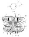
- FIG. 1is a diagram illustrating an embodiment of a human power generating system.
- FIG. 2is a block diagram illustrating an embodiment of a human power generating system.
- FIGS. 3A and 3Bare diagrams illustrating embodiments of a human power generating system.
- FIGS. 4A and 4Bare diagrams illustrating embodiments of a case for a human power generating system.
- FIGS. 5A and 5Bare diagrams illustrating embodiments of a shaft, sealed bearing, and bobbin of a human power generating system.
- FIG. 6is a diagram illustrating an embodiment of bobbin and spring rewinder of a human power generating system.
- FIGS. 7A , 7 B, and 7 Care diagrams illustrating embodiments of pulling configurations for a human power generating system.
- FIGS. 8A and 8Bare block diagrams illustrating embodiments of a shaft, sealed bearing, and bobbin of a human power generating system.
- FIGS. 9A and 9Bare diagrams illustrating embodiments of fairlead holes.
- FIGS. 10A and 10Bare block diagrams illustrating embodiments of a generator.
- FIG. 11is a diagram illustrating an embodiment of the wiring of a stator and the magnets and inertial mass of a rotor.
- FIGS. 12A , 12 B, and 12 Care diagrams illustrating embodiments of a human power generating system.
- FIG. 13is a diagram illustrating an embodiment of an integral anchoring attachment for a power generating unit.
- FIGS. 14A and 14Bare diagrams illustrating embodiments of connector systems for a power generating unit case.
- FIGS. 15A and 15Bare graphs illustrating the power generated from a human power generating system in two embodiments.
- FIG. 16is a diagram illustrating an embodiment of a circuit board.
- FIG. 17is a diagram illustrating an embodiment of an output cable and connector.
- FIG. 18is a diagram illustrating an embodiment of a retraction circuit.
- the inventioncan be implemented in numerous ways, including as a process, an apparatus, a system, a composition of matter, a computer readable medium such as a computer readable storage medium or a computer network wherein program instructions are sent over optical or communication links.
- these implementations, or any other form that the invention may take,may be referred to as techniques.
- a componentsuch as a processor or a memory described as being configured to perform a task includes both a general component that is temporarily configured to perform the task at a given time or a specific component that is manufactured to perform the task.
- the order of the steps of disclosed processesmay be altered within the scope of the invention.
- the term ‘processor’refers to one or more devices, circuits, and/or processing cores configured to process data, such as computer program instructions.
- a durable handheld portable human power generation systemthat is able to provide sufficient power to supply an appliance such as a computer has a number of constraints placed on its system. For example, durability implies keeping the number of breakable (e.g., moving) parts down, and handheld and portable imply constraining the size of the unit. Gears can be used to increase the spinning speed of a generator to increase the output voltage, but have the draw back of taking up space and being a moving part that can wear out.
- a gearless power generating unitis disclosed.
- a stringis configured to be pulled.
- the stringis configured such that a large motion (e.g., a full arm pull, a step, etc.) is used to pull the string.
- a bobbinis configured to rotate when the string is unwound from the bobbin as the string is pulled.
- An electric power generatorhaving a rotor that is configured to rotate such that the number of rotations of the rotor and the bobbin is 1:1 when the string is being pulled.
- the stringis rewound on the bobbin when the string is retracting.
- a spring, a motor driven using a retraction circuite.g., the electric power generator used as a motor
- any other appropriate force sourceis used to retract the string.
- the bobbinis coupled to a shaft.
- the shaftis coupled to a clutch, and the clutch is coupled to the rotor of the electric power generator.
- the clutchenables the shaft rotation when the string is being pulled to rotate the rotor.
- the clutchdoes not enable the shaft rotation when the string is being retracted to rotate the rotor.
- the power generating unitwhen the string is being retracted, can continue to output power if the power is stored in a rotating mass (e.g., a steel cap included as part of the rotor), a battery or a capacitor.
- a rotating masse.g., a steel cap included as part of the rotor
- a battery or a capacitore.g., a battery or a capacitor.
- an output power limiteris used to limit output power of the power generating unit such that output power is available when the string is being retracted by ensuring that there is power remaining in the stored rotating mass, battery, or capacitor that can be drawn on during the time when the string is retracting.
- retraction of the stringis caused using a second string.
- the second stringis wound on the bobbin such that when the first string unwinds, the second string winds, and when the second string unwinds, the first string winds.
- a usercan pull alternately on one string and then the other.
- a spring or motoris not required to rewind the string, and a clutch is not required to connect the shaft to the rotor.
- a mass or electrical storageis also not required to enable the power generating unit to output power when the first string is retracted.
- the first and second stringcomprise one string, wherein the middle of the string is coupled to the bobbin and one end of the string is used as the first string and the other end of the string is used as the second string.
- the stringis anchored at one end to the case of the power generating unit.
- the other end of the stringis wound and unwound on the bobbin.
- the stringis pulled by pulling on a wheel around which the string is passed. Pulling on the wheel unwinds the string from the bobbin on one end and pulls against the other end anchored on the case.
- a pull of the wheel of a distance ‘x’ away from the casecauses the string to be unwound a distance twice ‘x’ from the bobbin.
- a usercan generate more power using the extra wheel configuration since the bobbin will rotate twice as fast.
- the extra wheel configurationacts as a pulley.
- a power generating unitis anchored to a fixed object enabling a user to operate the power generating unit without holding the unit in one hand.
- the power generating unitis anchored using an integral anchoring attachment.
- a strapis coupled to the power generating unit case on both ends, where one end is coupled using a detachable coupler (e.g., a hook, a clip, a snap, etc.).
- the electric power generating unitincludes a sealed chamber and a chamber that can be opened.
- the sealed chamberprotects the electric power generator from environmental contamination.
- the chamber that can be openedallows the string, bobbin, and spring (if appropriate) to be accessed.
- the sealed chamberis sealed using a sealed bearing around a shaft between the sealed chamber and the chamber that can be opened.
- the sealed chamberis sealed using the bottom of the case coupled to the middle hour-glass shaped case.
- a power generating unitis mechanically coupled to an animal, the wind, a water wheel, or any other appropriate source of mechanical energy.
- FIG. 1is a diagram illustrating an embodiment of a human power generating system.
- user 100holds power generation unit 102 in hand 104 .
- User 100pulls on string 106 using hand 108 .
- hand 108pulls on a handle (not shown in FIG. 1 ) that attaches to string 106 .
- String 106mechanically causes a generator in power generation unit 102 to produce electric power.
- String 106has a length that is sufficient to allow a long pulling motion from user 100 .
- one handis used to pull on string 106
- two handsare used to pull on string 106
- one foot/legis used to pull on string 106
- two feet/legsare used to pull on string 106 , or any other appropriate human mechanical motion.
- an appropriate mechanical motion source other than humanis used to pull on string 106 —for example, an animal motion, a wind motion, etc.
- FIG. 2is a block diagram illustrating an embodiment of a human power generating system.
- mechanical power source 202is coupled to electrical power generator 204 .
- Electrical power generator 204generates power using the motion generated by mechanical power source 202 .
- Electrical power generator 204provides a signal indicating mechanical activity (e.g., revolutions per minute (RPM) due to mechanical power source 202 input to electrical power generator 204 ) to controller and memory 212 .
- Controller and memory 212process information provided by the signal indicating mechanical activity and provide feedback to mechanical power source 202 (e.g., to a user pulling on a string). Feedback to mechanical power source 202 is provided using user feedback device 214 .
- RPMrevolutions per minute
- user feedback device 214comprises a light, a variable intensity light, a flashing light, a variable frequency flashing light, a sound, a variable pitched sound, a variable intensity sound, a vibration generator, or any other appropriate feedback device.
- user feedbackprovides information regarding desired pacing of pulls, power generated (e.g., over/under power ratings), or any other appropriate user feedback information.
- Electrical power generator 204provides alternating current generated power to rectifier 206 .
- Rectifier 206rectifies the alternating current generated power output to provide direct current power output.
- the voltage of the direct current power outputis converted to a higher or a lower voltage and/or smoothed using a capacitor, or any other appropriate output conditioning.
- Rectifier 206outputs to control gate 208 .
- Control gate 208is able to switch the power input to control gate 208 using a pulse width modulated switch before outputting to battery 210 .
- Control gate 208is switched based on a control signal from controller and memory 212 .
- the rectifieris a passive rectifier or is an active rectifier (e.g., a synchronous rectifier).
- the control gate 208 and rectifier 206are combined using the switches of the active rectifier to pulse width modulate the output.
- mechanical power source 202comprises a string being pulled, two strings being pulled, a bicycle, a rowing machine, a step machine, a treadmill, a windmill, a water wheel, or any other appropriate mechanical power source.
- a rotating mechanical power sourceis coupled to the rotating rotor of the power generating unit without the use of a string to cause a bobbin to rotate.
- control gate 208outputs to an electrical device 214 such as laptop 212 , lamp 216 , an LED light source, cell phone charger 218 , radio 222 , an entertainment device, flashlight 220 , water purifier 224 (e.g., a UV water purifier), or any other appropriate device requiring electrical power.
- control gate 208is coupled to battery 210 or a capacitor to condition the power output from control gate 208 .
- the power stored in battery 210can be used to run any appropriate device requiring electrical power.
- the average electrical power output from the deviceis at least 10 W.
- consumer devicesthat consume ⁇ 1 W of power (e.g., cell phones, iPodsTM, GameboysTM, global positioning system devices, cameras, lighting, etc.). Because there have been several psychological studies that show that people need at least a 10:1 reward to effort ratio for them to feel like an endeavor is worthwhile, a usage ratio of at least 10 to 1 (i.e., 10 minutes of use for 1 minute of effort) is targeted. Therefore, 10 W is a useful target for the design of the human power generating system.
- FIGS. 3A and 3Bare diagrams illustrating embodiments of a human power generating system.
- power generating unit 300is shown in a top view with a line 301 indicating a cut view line for FIG. 3B .
- power generating unitincludes bottom of case 302 , middle hour glass of case 304 , top of case 306 .
- String 308is wrapped around the center of bobbin 310 .
- String 308is secured to bobbin 310 at one end. The other end of string 308 passes out a fairlead hole 309 .
- the other end of string 308is attached to a handle that enables a user to pull string 308 , unwinding string 308 from bobbin 310 .
- Bobbin 310rotates while string 308 unwinds.
- string 308is rewound around bobbin 310 by turning bobbin 310 using spring 312 .
- the outer end of spring 312is coupled to a housing that is in turn coupled to top of case 306 (not shown in FIG. 3B ).
- the inner end of spring 312is couple to bobbin 310 (not shown in FIG. 3B ).
- bobbin 310compresses energy into spring 312 .
- the compressed energy in spring 312is used to rewind string 308 around bobbin 310 .
- spring 312is not included in power generating unit 300 (e.g., a motor is used to rewind string 308 on bobbin 310 or a second string on bobbin 310 is used to rewind a first string such as string 308 ).
- bobbin 310rotates and turns shaft 314 .
- Shaft 314is coupled to bobbin 310 by having a keyed hole in bobbin 310 into which a corresponding keyed shaft 314 mates.
- the keyed holecomprises a “D” shaped hole, a star shaped hole, a square hole, a hexagonal hole, a single flat, a dual flat, splined, or any other appropriate keyed hole enabling a rotation of bobbin 310 to be transmitted to shaft 314 .
- Shaft 314is coupled to sealing bearing 316 . Sealing bearing 316 seals the lower chamber from the upper chamber.
- the upper chambercan be opened by opening top of case 306 and separating top of case 306 from middle hour glass of case 304 . Opening the upper chamber allows access to the keyed end of shaft 314 , bobbin 310 , string 308 , and spring 312 .
- the lower chamberis sealed to prevent environmental contamination from affecting the electronic components in the lower chamber.
- the lower chamber contentsinclude clutch 322 , rotor 324 , stator 326 , and circuit board 328 .
- Clutch 322couples shaft 314 to rotor 324 .
- Clutch 322enables a rotation of bobbin 310 to be transmitted to rotor 324 when string 308 is being unwound (e.g., as a user pulls string 308 ).
- Rotor 324rotates with a ratio of 1:1 with a rotation of bobbin 310 .
- Clutch 322does not enable a rotation of bobbin 310 to be transmitted to rotor 324 when string 308 is being rewound (e.g., as string 308 is rewound on bobbin using, for example, a spring force).
- Rotor 324includes magnets (not indicated in FIG. 3B ). In some embodiments, rotor 324 includes an inertial mass (not indicated in FIG. 3B ). Stator 326 includes wire windings in which the current is generated from the motion of bobbin 310 and rotor 324 .
- Handle 330detaches from the top of the hour glass case and is attached to one end of string 308 after passing out fairlead hole 309 .
- Handle 330can be pulled by a user to cause rotation of bobbin 310 .
- Strap 332can be used to anchor the power generating unit to a fixed object. A user can then pull on handle 330 without holding the case of the power generating unit. A user fatigues less quickly if only pulling on handle 330 and not also providing an anchoring force for the case than if pulling and anchoring.
- FIGS. 4A and 4Bare diagrams illustrating embodiments of a case for a human power generating system.
- the case of FIGS. 4A and/or 4 Bcomprise bottom of case 302 , middle hour glass of case 304 , top of case 306 of FIG. 3 B.
- the case for a human power generating systemincludes top of case 400 , middle hour glass of case 402 , and bottom of case 404 .
- Top of case 400 and middle hour glass of case 402form upper chamber 406 .
- a bobbin, on which a string is wound,is accessible upon opening of top of case 400 .
- the stringpasses out of upper chamber 406 through fairlead hole 410 .
- Middle hour glass of case 402 and bottom of case 404form lower chamber 408 .
- Lower chamber 408is designed to prevent the environment from affecting the electronic components of the power generating unit.
- Bottom of case 404seals against middle hour glass of case 402 so that lower chamber 408 is sealed from environmental contamination (e.g., dust, dirt, water, etc.).
- the seal between bottom of case 404 and middle hour glass of case 402is sealed using ultrasonic welding, adhesive, an o-ring, a gasket, sealant, or any other appropriate way of achieving a seal.
- the case for a human power generating systemincludes top of case 450 , middle hour glass of case 452 , and bottom of case 454 .
- Top of case 450 and middle hour glass of case 452form upper chamber 456 .
- a bobbin, on which a string is wound,is accessible upon opening of top of case 450 .
- the stringpasses out of upper chamber 456 through fairlead hole 460 .
- Middle hour glass of case 452 and bottom of case 454form lower chamber 458 .
- Lower chamber 458is designed to prevent the environment from affecting the electronic components of the power generating unit.
- Bottom of case 454seals against middle hour glass of case 452 so that lower chamber 458 is sealed from environmental contamination (e.g., dust, dirt, water, etc.).
- environmental contaminatione.g., dust, dirt, water, etc.
- the seal between bottom of case 454 and middle hour glass of case 452is sealed using ultrasonic welding, adhesive, an o-ring, a gasket, sealant, or any other appropriate way of achieving a seal.
- FIGS. 5A and 5Bare diagrams illustrating embodiments of a shaft, sealed bearing, and bobbin of a human power generating system.
- bobbin 500includes top post 502 which is slit to hold one end of a spring. The spring provides a rewinding force on bobbin 500 enabling bobbin 500 to rewind the string after a user has pulled the string to unwind it.
- Keyed end 504 of shaft 506is fit through sealed bearing 508 into the bottom of bobbin 500 . Keying enables a rotation of bobbin 500 to be efficiently translated to a rotation of shaft 506 , while also allowing easy removal of bobbin 500 from shaft 506 .
- Sealed bearing 508holds shaft 506 and seals the opening between an upper and lower chamber of a case for a human power generating unit.
- Shaft 506couples to a rotor of a generator in the lower chamber of the case.
- bobbin 550includes top post 552 which is slit to hold one end of a spring.
- the springprovides a rewinding force on bobbin 550 enabling bobbin 550 to rewind string 560 after a user has pulled string 560 to unwind it.
- string 560is coupled to bobbin 550 by passing through a hole in the axis post or side wall of bobbin 550 and tying a knot or tying a knot with the rest of string 560 (e.g., wrapping string 560 around the post of bobbin 560 and tying a knot to string 560 on the side where it entered the hole), or any other appropriate manner of coupling string 560 to bobbin 550 .
- Keyed end of shaft 556is fit through sealed bearing 558 into the bottom of bobbin 550 . Keying enables a rotation of bobbin 550 to be efficiently translated to a rotation of shaft 556 , while also allowing easy removal of bobbin 550 from shaft 556 .
- Sealed bearing 558holds shaft 556 and seals the opening between an upper and lower chamber of a case for the human power generating unit.
- Shaft 556couples to a rotor of a generator in the lower chamber of the case.
- the string 560is chosen to be between 0.5 and 2 meters in length allowing a user to use a large motion when pulling on the string. During typical use a user maintains a consistent pace of pulling the string between 0.5 and 1.5 meters during each pull at a rate of one pull and one retraction each 0.5 to 1.5 seconds.
- the diameter of bobbin 580 and the diameter of string 560are both chosen to achieve a certain minimum rotational speed of shaft 506 .
- the diameter of bobbin 580is chosen to be 9 mm, and the string diameter is chosen to be between 1 and 2 mm. For a typical user pulling a string 1 meter at a rate of one pull and one retraction each second, shaft 506 will rotate at a speed of 3000 RPM.
- the diameter of bobbin 580is chosen to be between 6 and 12 mm, and the string diameter is chosen to be between 0.5 and 4 mm.
- the speed of rotation of shaft 506can be increased by decreasing the diameter of bobbin 580 or the diameter of the string, but there are tradeoffs: a smaller diameter of bobbin 580 will be more fragile and will also cause the string to rotate around a smaller radius of curvature, thus impacting the lifetime of the string; a smaller diameter string will have lower breaking strength and will abrade faster, thus decreasing lifetime.
- a choice of diameter of bobbin 580 and string diameterare made to achieve a long lifetime while still achieving a useful minimum rotational speed.
- FIG. 6is a diagram illustrating an embodiment of bobbin and spring rewinder of a human power generating system.
- spring 602 outer endis coupled with holding case 604 by having tab 603 at the outer end of spring 602 inserted into a slit of holding case 604 (not shown in FIG. 6 ).
- Holding case 604is coupled to top of case 600 along with clamp ring 608 using one or more screws—represented in FIG. 6 by screws 606 .
- Clamp ring 608loosely couples bobbin 612 to top of case 600 , such that bobbin 612 can freely rotate.
- Top post of bobbin 611remains engaged with spring 602 even after the rewinder assembly is removed from the rest of the device.
- Slit 614 on top post of bobbin 611couples with inner end of spring 602 such that when string 610 is wound on bobbin 612 , spring 602 unwinds. And, when string 610 is unwound on bobbin 612 , spring 602 winds.
- spring 602is selected such that spring 602 does not “bottom out” upon fully unwinding string 610 from bobbin 612 .
- the diameter of the middle of the bobbin 613is designed in order that when string 610 is pulled bobbin 612 turns rapidly enough to achieve a desired power output level. In some embodiments, the diameter is chosen to be in the range of 6 to 10 mm.
- slit 614 of bobbin 612is used to engage spring 602 and preload spring 602 .
- FIGS. 7A , 7 B, and 7 Care diagrams illustrating embodiments of pulling configurations for a human power generating system.
- power generating unit 700includes bobbin 706 which turns when string 702 winds or unwinds on bobbin 706 .
- String 702unwinds when handle 704 is pulled away from power generating unit 700 .
- String 702winds when handle 704 is let loose and a spring or motor enables string 702 to be retracted.
- power generating unit 730includes bobbin 740 .
- Bobbin 740turns when string 732 winds or unwinds on bobbin 740 or when string 736 winds or unwinds on bobbin 740 .
- String 732unwinds when handle 734 is pulled away from power generating unit 730 .
- String 736unwinds when handle 738 is pulled away from power generating unit 730 .
- String 732winds when handle 734 is let loose and handle 738 is pulled.
- String 736winds when handle 738 is let loose and handle 734 is pulled.
- string 732is the same or is different from string 736 .
- power generating unit 760includes bobbin 770 which turns when string 762 winds or unwinds on bobbin 770 .
- String 762unwinds when handle 768 is pulled away from power generating unit 760 .
- Handle 768pulls on wheel 764 around which string 762 is wrapped.
- String 762is anchored on power generating unit 760 using anchor 766 .
- For a pull of handle 768 a distance ‘x’ away from power generating unit 760a length of string 762 two times distance ‘x’ is pulled off of bobbin 770 .
- String 762winds when handle 768 is let loose and a spring or motor enables string 762 to be retracted.
- more complex pulley arrangementsare used instead of the simple pulley shown in FIG. 7C . These pulley arrangements can be used when the mechanical pulling force is sufficient for pulling the increased force required by using a complex pulley.
- FIGS. 8A and 8Bare block diagrams illustrating embodiments of a shaft, sealed bearing, and bobbin of a human power generating system.
- bobbin 800includes keyed hole 802 which enables keyed end 810 of shaft 812 to couple with bobbin 800 .
- Bobbin 800includes top winding space 804 for a first string to be wound in a first direction and bottom winding space 806 for a second string to be wound in a second direction. Pulling on the first string unwinds the first string and rewinds the second string. Pulling on the second string unwinds the second string and rewinds the first string.
- Keyed end 810 of shaft 812is fit through sealed bearing 808 through bobbin 800 .
- Bobbin 800is secured on shaft 812 using clip ring 814 which is inserted into clip ring slot 816 on shaft 812 . Keying enables a rotation of bobbin 800 to be efficiently translated to a rotation of shaft 812 .
- Sealed bearing 808holds shaft 812 and seals the opening between an upper and lower chamber of a case for a human power generating unit.
- Shaft 812couples to a rotor of a generator in the lower chamber of the case.
- bobbin 850In the example shown in the compressed projection view in FIG. 5B , bobbin 850 .
- String 854is wound around bottom winding space (not indicated in FIG. 5B ) of bobbin 850
- string 856is wound around top winding space (not indicated in FIG. 5B ) of bobbin 850 .
- Pulling on the string 854unwinds the string 854 and rewinds the string 856 .
- Pulling on the string 856unwinds the string 856 and rewinds the string 854 .
- no spring or motoris required to rewind string 856 , so that hardware associated with string 856 is not used.
- string 854 and/or string 856is coupled to bobbin 850 by passing through a hole in the axis post or side wall of bobbin 850 and tying a knot or tying a knot with the rest of string 854 or string 856 respectively (e.g., wrapping string 854 around the post of bobbin 850 and tying a knot to string 854 on the side where it entered the hole), or any other appropriate manner of coupling string 854 and/or string 856 to bobbin 850 .
- Keyed end 860 of shaft 862is fit through sealed bearing 858 and through bobbin 850 .
- Bobbin 850is secured to shaft 862 using clip ring 864 .
- Sealed bearing 858holds shaft 862 and seals the opening between an upper and lower chamber of a case for the human power generating unit.
- Shaft 862couples to a rotor of a generator in the lower chamber of the case.
- bobbin 850When using bobbin 850 (or bobbin 800 ), a restoring spring is not used. Further, an inertial mass for storing energy during the retraction of a string is also not used. A clutch is not required to only transmit rotation of bobbin 850 (or bobbin 800 ) to a generator rotor in one rotational direction.
- FIGS. 9A and 9Bare diagrams illustrating embodiments of fairlead holes.
- middle hour glass case 900includes an opening for fairlead 902 .
- Fairlead 902creates a fairlead hole through which a string can pass.
- the fairlead holeis designed to minimize wear on the string as the string is pulled out and retracted in through the fairlead hole.
- Fairlead 902is designed such that the string spends as little time against the side wall of fairlead 902 as possible (e.g., the opening is bigger than the diameter of the string—for example, an opening of approximately 3.75 mm by 27 mm with a string diameter of 1 to 2 mm).
- the edge of fairlead 902is given a profile that reduces the angle of bending when the string bends around fairlead 902 .
- an elliptical curve, a substantially elliptical, a portion of an elliptical curve, or any other appropriate curve for reducing bendingis used for the wall of fairlead 902 .
- middle hour glass case 930includes an opening for fairlead 932 .
- Fairlead 932creates two fairlead holes through which two strings can pass.
- the fairlead holesare designed to minimize wear on the strings as each string is pulled out and retracted in through each fairlead hole.
- Fairlead 932is designed such that the string spends as little time against the side wall of fairlead 932 as possible (e.g., the opening is bigger than the diameter of the string—for example, an opening of between approximately 3.75 mm and 6 mm tall by 20 mm wide with a string diameter of 1 to 2 mm).
- the edge of fairlead 932is given a profile that reduces the angle of bending when the string bends around fairlead 932 for a typical use.
- an elliptical curve, a substantially elliptical, a portion of an elliptical curve, or any other appropriate curve for reducing bendingis used for the wall of fairlead 932 .
- FIG. 9Cis a block diagram illustrating an embodiment of a fairlead wall.
- string 960bends around fairlead wall 962 .
- a typical usehas string 960 bent at small angles around fairlead wall 962 .
- a stretched shape similar to an ellipsehas less bending to string 960 than a common circular fairlead wall profile. More bending leads to greater wear, so the stretched shape similar to an elliptical profile leads to longer string life.
- FIGS. 10A and 10Bare block diagrams illustrating embodiments of a generator.
- shaft 1014is coupled to sealed bearing 1012 .
- Shaft 1014has keyed end 1016 which couples to a mechanical energy source (e.g., a bobbin caused to rotate by pulling a string).
- Shaft 1016is coupled to clutch 1006 .
- Clutch 1006allows rotation of shaft 1016 to be translated to a rotation of rotor in one direction (e.g., the direction of rotation when a string is pulled rotating a bobbin coupled to shaft 1016 ).
- clutch 1006comprises a needle roller clutch.
- Clutch 1006is coupled to rotor cap 1002 using hex nut 1000 .
- Rotor cap 1002is coupled to magnet ring 1004 .
- Bearing 1008allows clutch 1006 to turn and stator 1010 to remain stationary.
- inertial massstores energy when a string is retracting, and so rotor cap 1002 is made more massive (e.g., made out of steel, made of two metals such as lead and steel).
- inertial massdoes not store energy when a string is retracting, and so is kept as light as possible (e.g., made out of plastic)—for example, in the push-pull string configuration shown in FIG. 7B .
- shaft 1044is coupled to sealed bearing 1042 .
- Shaft 1044has keyed end 1046 which couples to a mechanical energy source (e.g., a bobbin caused to rotate by pulling a string).
- Shaft 1046is coupled to clutch 1036 .
- Clutch 1036allows rotation of shaft 1046 to be translated to a rotation of rotor in one direction (e.g., the direction of rotation when a string is pulled rotating a bobbin coupled to shaft 1046 ).
- clutch 1036comprises a needle roller clutch.
- Clutch 1036is coupled to rotor cap 1032 using keyed torque transmitter 1030 (e.g., a hex nut).
- keyed torque transmitter 1030comprises a star nut, a square nut, a double-D nut, a D nut, a hex nut, or any other appropriate shape enabling firm or non-slipping coupling between a clutch and a rotor. If rotor cap 1032 is made of a soft material such as plastic, and the keyed torque transmitter 1030 is not included, then the clutch 1036 will slip when delivering torque to rotor cap 1032 . Rotor cap 1032 is coupled to magnet ring 1034 . Bearing 1038 allows clutch 1036 to turn and stator 1040 to remain stationary.
- FIG. 11is a diagram illustrating an embodiment of the wiring of a stator and the magnets and inertial mass of a rotor.
- inertial mass 1100is coupled to magnets that alternate their polarity.
- the inertial masscomprises a steel cap with an outer diameter of approximately 70 mm.
- magnet 1102 and magnet 1104present a magnetic field with opposite polarities to a stator core and stator windings such as stator core 1106 and windings 1108 .
- inertial mass 1100comprises a steel ring with inner radius approximately 65 mm, outer radius approximately 70 mm, height approximately 20 mm, and mass 200 g.
- windings 1108are configured in 3 phases, such that every third armature is connected together.
- windings 1108comprise 30 turns of wire per armature, and the wire is 0.6 mm in diameter such that a rotational speed on the motor of 3000 RPM results in an open-circuit voltage of 18.3 V, and when connected to a 10 Ohm load the voltage is 11.3 V.
- Windings 1108are designed such that the trade off of the sizing of the wire, due to spatial constraints, and the length of the wire, due to a resistance constraint/power loss constraint, are appropriately made to achieve a human power generating unit capable of delivering 20 W into a target device load when the generator is rotating at 3000 RPM.
- inertial mass 1100is designed such that when a user operates the power generating unit pulling the string to achieve a rotation of the rotor of 360° rotations per minute (RPM), the power generating unit is able to provide constant power of 15 W by storing energy in the rotating inertial mass when the string is unwinding and then delivering that stored energy during the rewinding of the string.
- the energy output from the deviceis limited to 15 W during the string unwinding so that the extra energy can be stored as rotational energy in the inertial mass.
- An electrical power generatormay be modeled by a speed-controlled voltage source, in series with a Thevenin resistance.
- a small radius generatorIf a small radius generator is used, the magnet mass that can be effectively used is small. This means the amount of energy absorbed per rotation is also small. A problem is that this dictates low power outputs for reasonable shaft rotation speeds. In other words, a small radius results in a small value of k, above.
- a electrical power generatorTo couple the electrical power generator effectively to human body motions without the use of gears, a electrical power generator must be chosen with large enough k. Since k varies as the physical volume of the electrical power generator, this condition dictates, for a given magnet quality, a minimum physical volume for the electrical power generator.
- an electrical power generatorwith a sufficiently large enough physical volume, one may choose to make it axially long and/or radially fat. But while volume is proportional to r ⁇ 2*length, the area of magnets required is proportional to only r*length. In order to make economic use of magnets, it is advantageous to maximize r.
- short, fat generatorsare thus chosen typically with a diameter to length ratio of between 4 and 6, although other ratios can also be used.
- a wire diameteris selected for the windings to match the output voltage at a humanly realizable speed, to the voltage of the batteries being charged, or the desired input voltage of the equipment to be run. This speed is called the “cut in” speed.
- the cut-in speedshould be lower than the average expected use speed, called “design speed” throughout this specification. In some embodiments, the cut-in speed is chosen to be about one third of the design speed.
- FIGS. 12A , 12 B, and 12 Care diagrams illustrating embodiments of a human power generating system.
- user 1200 using hand 1202 and hand 1204pulls on string 1203 and string 1205 , respectively, which are coupled to power generating unit 1206 .
- String 1203 and string 1205cause a rotor to turn in power generating unit 1206 and, thereby, electric power to be generated.
- power generating unit 1206includes an integral strap 1208 that enables power generating unit 1206 to be anchored to a fixed object (e.g., fixed object 1210 ).
- strap 1206is anchored to a strap, a tree, a post, a fixed ring, a tether, or any other appropriate object to anchor power generating unit 1206 .
- power generating unit 1236includes an integral strap 1238 that enables power generating unit 1236 to be anchored to a fixed object (e.g., belt 1240 ).
- power generating unit 1266includes an integral strap 1268 that enables power generating unit 1266 to be anchored to a fixed object (e.g., foot 1270 ).
- FIG. 13is a diagram illustrating an embodiment of an integral anchoring attachment for a power generating unit.
- power generating unit 1300includes post 1302 and post 1306 .
- Strap 1304is constrained by post 1302 so that strap is integral to power generating unit 1300 .
- Strap 1304is coupled to hook 1308 using pass through holes 1310 .
- Hook 1308can be released from and can be hooked around post 1306 .
- power generating unit 1300is anchored (e.g., as is shown in FIG. 13 where power generating unit 1300 is anchored to pole 1312 ).
- Anchoring power generating unit 1300enables a user to generate power by pulling on the strings of power generating unit 1300 (not shown in FIG. 13 ) with less fatigue then when also anchoring power generating unit 1300 by holding with a hand. Additionally, anchoring improves the use of the push-pull configuration as shown in FIG. 12A .
- FIGS. 14A and 14Bare diagrams illustrating embodiments of connector systems for a power generating unit case.
- middle hour glass case 1400includes a first connector system (e.g., threads 1402 ) for connecting middle hour glass case 1400 to top of case 1404 .
- the chamber formed by middle hour glass case 1400 and top of case 1404is designed to hold a primary mechanical turning source such as a bobbin that rotates as a string is wound or unwound in response to a string being pulled or retracted.
- a primary mechanical turning sourcesuch as a bobbin that rotates as a string is wound or unwound in response to a string being pulled or retracted.
- the first connector systemcomprises a bayonet connector system (e.g., push and twist to lock), a sleeve mount (e.g., a cylinder, square, or hexagon that top of case 1404 slide down and locks via friction, set screw, thumb screw, latch, etc.), a spline mount, a clip connector system, a snapping connector system, or any other appropriate connector system for connecting top of case 1404 and middle hour glass case 1400 .
- a bayonet connector systeme.g., push and twist to lock
- a sleeve mounte.g., a cylinder, square, or hexagon that top of case 1404 slide down and locks via friction, set screw, thumb screw, latch, etc.
- a spline mounte.g., a cylinder, square, or hexagon that top of case 1404 slide down and locks via friction, set screw, thumb screw, latch, etc.
- a spline mounte.g., a cylinder, square, or hexagon that
- a second connector system(e.g., screw holes 1450 ) is also included in middle hour glass case 1452 (shown as a top view in FIG. 14B ).
- the second connector systemenables middle hour glass case 1452 to be attached or coupled to a secondary mechanical turning source for turning the shaft of the power generating system of middle hour glass case 1452 .
- a bicycle, turn wheel, propeller, a belt, or any other mechanical turning source for the shaftis coupled to the power generating system and the second connector system is used to mount the power generating system appropriately.
- Thisenables the power generating system to take advantage of any mechanical turning source of energy including animals, wind mills, exercise devices (e.g., bicycles, walkers, rowing machines, step machines, etc.), water wheels, etc.
- FIGS. 15A and 15Bare graphs illustrating the power generated from a human power generating system in two embodiments.
- poweris generated during the time when the string is being pulled causing a rotor in a generator to turn.
- output poweris limited to 15 W.
- Poweris not generated during the time when the string is being retracted as indicated by region 1502 in the graph.
- X-axis of the graphindicates the amount of power generated, and y-axis of the graph indicates time.
- the output of the power generating unitis essentially constant.
- energy that is generatedis both output from the unit and also stored in a stored energy source.
- energyis drained from the stored energy source.
- Time region when the power is constant 1510is larger than the time when the stored energy source cannot keep the output power constant 1512 .
- the stored energy source for FIG. 15Bcomprises a 0.3 F super capacitor.
- output poweris limited to 15 W.
- X-axis of the graphindicates the amount of power generated, and y-axis of the graph indicates time.
- the output of the power generating unitis essentially constant.
- energy that is generatedis both output from the unit and also stored in a stored energy source.
- energyis drained from a stored energy source.
- Time region when the power is constant 1520is larger than the time when the stored energy source cannot keep the output power constant 1522 .
- the stored energy source for FIG. 15Ccomprises an inertial mass that stores rotational energy.
- output poweris limited to 15 W.
- X-axis of the graphindicates the amount of power generated, and y-axis of the graph indicates time.
- the output power generating unit outputcan be further regulated using an output power limiter.
- the output power limiterdetermines the total power generated in a cycle of pulling and retracting and sets the overall output level such that a constant output can be achieved. In other words, the reserve power in the stored energy source is sufficient to provide the output power during the retracting of the string.
- Output powercan be limited by switching a switch to disconnect the output from the power generation circuitry in the power generating unit.
- power outputis limited by a receiving device (e.g., an input to a laptop power supply).
- a receiving devicee.g., an input to a laptop power supply.
- FIG. 16is a diagram illustrating an embodiment of a circuit board.
- the circuit board of FIG. 16comprises circuit board 328 of FIG. 3B .
- circuit boardreceives current at contact 1600 , contact 1602 , and contact 1604 produced by generator from coils in stator.
- Diodes 1606 , diodes 1608 , and diodes 1610rectify received current.
- Memory and controller 1612provides feedback to user and controls output power. Feedback to user is provided using light emitting diodes 1614 .
- Output poweris controlled using switch 1616 . Controlling output power also controls a resistance a user feels when pulling a string connected to generator. Output is connected to output contacts 1618 .
- FIG. 17is a diagram illustrating an embodiment of an output cable and connector.
- power generating unit 1700outputs power using cable 1702 .
- Cable 1702is coupled to connector 1704 which enables an electrical connection between cable 1702 and a circuit board of power generating unit 1700 (e.g., contacts 1618 of FIG. 16 ).
- Connector 1704provides strain relief with case of power generating unit 1700 in the event that cable 1702 is pulled.
- Connector 1704also provides sealing of the sealed chamber holding the electronics and generator of the power generator unit against contamination (e.g., water, dust, sand, etc.).
- FIG. 18is a diagram illustrating an embodiment of a retraction circuit.
- the circuitis used to have the generator act as a motor such that the generator can be used to retract the string back onto the bobbin.
- Motor 1800has three phases which are connected by three wires 1802 to six field effect transistors (FET's) 1804 .
- FET's 1804are selectively turned on or off by the control lines 1806 coming from controller 1808 .
- the output of FET's 1804is to battery/load 1810 .
- Monitor 1812monitors the amount of power being delivered to battery/load 1810 .
- controller 1808will selectively turn on/off FET's 1804 in such a way that they will synchronously rectify the AC output of the motor 1800 and deliver the rectified DC power to battery/load 1810 .
- monitor 1812provides a signal to controller 1808 when the power is no longer being delivered, such as when a user has finished pulling on a string.
- controller 1808can use FETs 1804 to drive motor 1800 in such a way as to rewind a string onto a bobbin, using a portion of the energy stored in battery/load 1810 . In this manner motor 1800 is used as both an energy generator and also as a string rewinder.
- controller 1808selectively turns on or off a control gate (not shown in FIG. 18 ) or FET's 1804 in order to adjust the amount of power flowing into battery/load 1810 .
- Hall effect sensors of motor 1800measure the rotational speed of motor 1800 and are monitored by controller 1808 .
- motor 1800When a user is pulling and unwinding the string from the bobbin, motor 1800 will produce power that is rectified (e.g., by a diode rectifier) that passes to battery/load 1810 . Once the user has finished pulling, the rotational speed of the motor will drop below a certain threshold for a certain time (i.e., the motor slows down for example to ⁇ 500 RPM for a time period of at least 100 ms).
- controller 1808can selectively turn on and off FET's 1804 using standard motor commutation in such a way that the energy stored in battery/load 1810 is used to rotate motor 1800 thereby rewinding the string onto the bobbin.
Landscapes
- Engineering & Computer Science (AREA)
- Power Engineering (AREA)
- Connection Of Motors, Electrical Generators, Mechanical Devices, And The Like (AREA)
Abstract
Description
V—oc=k*omega
P_max=½V—oc*½I—sc
I—sc=V—oc/R—thevenin
Therefore, P_max=V_oc^2/(4*R_thevenin)=k^2*omega^2/(4*R_thevenin). It may be shown that the maximum power point for any particular shaft speed is at half the open-circuit voltage, and half the short-circuit current.
Claims (16)
Priority Applications (2)
| Application Number | Priority Date | Filing Date | Title |
|---|---|---|---|
| US11/983,427US8093731B2 (en) | 2006-11-07 | 2007-11-07 | Gearless human power generation |
| PCT/US2008/002229WO2009061331A1 (en) | 2007-11-07 | 2008-02-20 | Gearless human power generation |
Applications Claiming Priority (3)
| Application Number | Priority Date | Filing Date | Title |
|---|---|---|---|
| US86477206P | 2006-11-07 | 2006-11-07 | |
| US86199906P | 2006-11-29 | 2006-11-29 | |
| US11/983,427US8093731B2 (en) | 2006-11-07 | 2007-11-07 | Gearless human power generation |
Publications (2)
| Publication Number | Publication Date |
|---|---|
| US20080150493A1 US20080150493A1 (en) | 2008-06-26 |
| US8093731B2true US8093731B2 (en) | 2012-01-10 |
Family
ID=39541854
Family Applications (1)
| Application Number | Title | Priority Date | Filing Date |
|---|---|---|---|
| US11/983,427Expired - Fee RelatedUS8093731B2 (en) | 2006-11-07 | 2007-11-07 | Gearless human power generation |
Country Status (1)
| Country | Link |
|---|---|
| US (1) | US8093731B2 (en) |
Cited By (10)
| Publication number | Priority date | Publication date | Assignee | Title |
|---|---|---|---|---|
| US20130119674A1 (en)* | 2011-11-10 | 2013-05-16 | Bamiji Regnault | Bamiji permanent magnet generator (bpmg) |
| US20130200631A1 (en)* | 2012-02-06 | 2013-08-08 | Innova Patent Gmbh | Roller, in particular track roller or carrying roller for cableway systems |
| US20140060367A1 (en)* | 2012-03-12 | 2014-03-06 | Omnitek Partners Llc | Gravity dropped small weapon electronic safe arm fuze and energy harvesting device for power generation onboard gravity dropped weapons |
| US20140225376A1 (en)* | 2013-02-10 | 2014-08-14 | Omnitek Partners Llc | Dynamo-Type Lanyard Operated Event Detection and Power Generators |
| US20170340915A1 (en)* | 2016-05-27 | 2017-11-30 | SCULPTABODY, Inc. | Portable exercise equipment |
| US10220261B1 (en)* | 2017-10-17 | 2019-03-05 | Julian Garsdean | Mountable resistance exercise device |
| US10263441B1 (en) | 2018-01-03 | 2019-04-16 | Gabriel Aslan | Electronic device case with charging mechanism |
| US10279210B2 (en)* | 2014-05-09 | 2019-05-07 | Albert Ky | Magnetic friction and viscous cylinder-piston resistance portable exercise equipment |
| US10376732B2 (en)* | 2017-10-17 | 2019-08-13 | Julian Garsdean | Mountable resistance exercise device |
| US11601000B2 (en)* | 2019-09-30 | 2023-03-07 | Power Pull Group Inc. | Mobile device charging apparatus including a mechanical wheel |
Families Citing this family (10)
| Publication number | Priority date | Publication date | Assignee | Title |
|---|---|---|---|---|
| US8093731B2 (en) | 2006-11-07 | 2012-01-10 | Potenco, Inc. | Gearless human power generation |
| US7747355B2 (en)* | 2006-11-07 | 2010-06-29 | Potenco, Inc. | Electrical power generator with adaptive coupling |
| US20080157637A1 (en)* | 2006-11-07 | 2008-07-03 | Potenco, Inc. | Secondary attachment for human power generation |
| US20080150378A1 (en)* | 2006-11-07 | 2008-06-26 | Potenco, Inc. | Human power generation using a pulley |
| US20100327604A1 (en)* | 2009-06-27 | 2010-12-30 | Shawn Zhu | Human powered pull strings generator |
| CN101958569A (en)* | 2010-10-15 | 2011-01-26 | 鸿富锦精密工业(深圳)有限公司 | Charging and power supply module and electronic device installed with the charging and power supply module |
| US20140357457A1 (en)* | 2011-05-31 | 2014-12-04 | Intelect B.V. | Portable Fitness Apparatus |
| CN108173391B (en)* | 2018-01-23 | 2019-07-26 | 奇瑞新能源汽车技术有限公司 | A kind of mechanical oscillation-device for converting electric energy of integrated mechanical rectification mechanism |
| CN110165829B (en)* | 2019-04-19 | 2024-03-22 | 浙江师范大学 | Drawing type field generator |
| US12100988B1 (en)* | 2023-04-13 | 2024-09-24 | Lewis DANIELS | Portable human powered electric power generating device |
Citations (141)
| Publication number | Priority date | Publication date | Assignee | Title |
|---|---|---|---|---|
| US2338263A (en) | 1941-02-20 | 1944-01-04 | William G Pankonin | Pencil sharpener |
| US2561601A (en) | 1948-02-24 | 1951-07-24 | Henry H Szonnell | Top and launcher |
| US2843333A (en) | 1954-09-14 | 1958-07-15 | Martin E Jones | Spinning ratchet reel |
| US2991584A (en) | 1958-07-07 | 1961-07-11 | Roy Mfg Company De | Gyroscopic toy |
| US3246424A (en) | 1963-04-11 | 1966-04-19 | Joseph E Gregory | Spinning toy launcher |
| US3370855A (en) | 1965-06-02 | 1968-02-27 | Ideal Toy Corp | Audio device |
| US3389915A (en) | 1965-10-18 | 1968-06-25 | Ideal Toy Corp | Audio device |
| US3408766A (en) | 1966-01-10 | 1968-11-05 | Fortunato S. Ajero | Toy comprising top and playing paddle and launcher |
| US3410564A (en) | 1965-07-27 | 1968-11-12 | Roger Duncan T | Miniature phonograph |
| US3466050A (en) | 1967-03-03 | 1969-09-09 | Ideal Toy Corp | Multimessage phonograph mechanism |
| US3468546A (en) | 1966-12-20 | 1969-09-23 | Lorraine Ind Inc | Sequential play phonograph |
| US3477728A (en) | 1967-02-06 | 1969-11-11 | Ideal Toy Corp | Cylinder-type talking mechanism |
| US3525527A (en) | 1968-06-20 | 1970-08-25 | Ideal Toy Corp | Selection mechanism for multimessage tape phonograph |
| US3545328A (en) | 1968-09-17 | 1970-12-08 | Andrew Abrams | Door chime music box |
| US3546808A (en) | 1968-12-12 | 1970-12-15 | Kohner Bros Inc | Twirling figurine toy |
| US3555720A (en) | 1969-03-24 | 1971-01-19 | Frank Dattilo | Flying propeller toy |
| US3561861A (en) | 1969-01-09 | 1971-02-09 | Kenner Products Co | Self-contained projector and screen unit |
| US3635479A (en) | 1968-09-21 | 1972-01-18 | Cia Ind De Novedades Plasticas | Sound reproducing apparatus |
| US3664673A (en) | 1969-11-18 | 1972-05-23 | Ideal Toy Corp | Tape talking mechanism |
| US3721039A (en) | 1970-04-29 | 1973-03-20 | D Cook | Toy figure with mechanism for blowing air |
| US3788509A (en) | 1972-01-28 | 1974-01-29 | Klm Co | Method and apparatus for sealing plastic closures to plastic containers |
| US3792490A (en) | 1972-02-01 | 1974-02-12 | V Wigal | Miniature sound recording and reproducing device |
| US3796284A (en) | 1972-03-10 | 1974-03-12 | Mattel Inc | Starting mechanism for toy with phonograph |
| US3834071A (en) | 1972-02-22 | 1974-09-10 | Marvin Glass & Associates | Doll with coordinated head and torso movement |
| US3848467A (en) | 1972-07-10 | 1974-11-19 | E Flavell | Proportioned resistance exercise servo system |
| US3851418A (en) | 1973-02-07 | 1974-12-03 | Marvin Glass & Associates | Animated doll |
| US3859749A (en) | 1972-12-18 | 1975-01-14 | Mattel Inc | Power tool toys |
| US3873817A (en) | 1972-05-03 | 1975-03-25 | Westinghouse Electric Corp | On-line monitoring of steam turbine performance |
| US3879887A (en) | 1973-11-15 | 1975-04-29 | Teton Toy Dev Company | Inflatable top |
| US3904210A (en) | 1974-02-19 | 1975-09-09 | Marvin Glass & Associates | Sound reproducing device |
| US3920503A (en) | 1972-01-28 | 1975-11-18 | K L M Company | Apparatus for sealing plastic closures to plastic containers |
| US3922813A (en) | 1972-06-22 | 1975-12-02 | Marvin Glass & Associates | Doll with motorized legs driven in unison and arms driven in unison thereby |
| US4057904A (en) | 1975-06-27 | 1977-11-15 | The United States Of America As Represented By The Secretary Of The Department Of Transportation | Self-adjusting string extensiometer |
| US4082267A (en) | 1976-05-12 | 1978-04-04 | Flavell Evan R | Bilateral isokinetic exerciser |
| US4145885A (en) | 1977-09-23 | 1979-03-27 | Yedidia Solell | Wave motor |
| US4207989A (en) | 1977-11-17 | 1980-06-17 | A/S Haustrup Plastic | Container with lid opening means |
| US4228360A (en) | 1979-06-08 | 1980-10-14 | Pablo Navarro | Wave motion apparatus |
| US4261562A (en) | 1978-12-22 | 1981-04-14 | Flavell Evan R | Electromagnetically regulated exerciser |
| US4339889A (en) | 1980-02-01 | 1982-07-20 | Mattel, Inc. | Multiple function doll |
| US4360860A (en)* | 1977-03-07 | 1982-11-23 | Johnson Hugh G | Self-contained hand held portable lantern-flashlight consisting of a manually operated generator and rechargeable batteries |
| US4413441A (en) | 1981-11-09 | 1983-11-08 | Mattel, Inc. | Multiple function doll |
| US4433404A (en) | 1981-07-24 | 1984-02-21 | Ozen Corporation | Variety playing sound reproducing device |
| US4455614A (en) | 1973-09-21 | 1984-06-19 | Westinghouse Electric Corp. | Gas turbine and steam turbine combined cycle electric power generating plant having a coordinated and hybridized control system and an improved factory based method for making and testing combined cycle and other power plants and control systems therefor |
| US4483096A (en) | 1983-03-17 | 1984-11-20 | Mattel, Inc. | Launching platform for inertia vehicle |
| US4539484A (en) | 1980-06-06 | 1985-09-03 | Suggs Louis F | Wave and tide powered generation apparatus |
| US4626336A (en) | 1985-05-02 | 1986-12-02 | Hewlett Packard Company | Target for sputter depositing thin films |
| US4663009A (en) | 1985-02-08 | 1987-05-05 | Hewlett-Packard Company | System and method for depositing plural thin film layers on a substrate |
| US4670820A (en) | 1985-11-15 | 1987-06-02 | Hasbro, Inc. | Animated night-light and music-box combination |
| US4674741A (en) | 1985-08-05 | 1987-06-23 | Bally Manufacturing Corporation | Rowing machine with video display |
| US4678184A (en) | 1984-01-20 | 1987-07-07 | Merobel - Societe Anonyme Fracaise | Constant force exercise device |
| US4701835A (en) | 1985-09-19 | 1987-10-20 | The United States Of America As Represented By The Secretary Of The Army | Multimode flashlight |
| US4770279A (en) | 1986-03-28 | 1988-09-13 | Nippo Sangyo Kabushiki Kaisha Co Ltd | One-way clutch |
| US4790921A (en) | 1984-10-12 | 1988-12-13 | Hewlett-Packard Company | Planetary substrate carrier method and apparatus |
| US4834363A (en) | 1987-05-26 | 1989-05-30 | Schwinn Bicycle Company | Bicycle racing training apparatus |
| US4930770A (en) | 1988-12-01 | 1990-06-05 | Baker Norman A | Eccentrically loaded computerized positive/negative exercise machine |
| US4938475A (en) | 1987-05-26 | 1990-07-03 | Sargeant Bruce A | Bicycle racing training apparatus |
| US5066867A (en) | 1986-07-07 | 1991-11-19 | Shim Hyun J | Method and device for generating electric power by use of wave force |
| US5067601A (en) | 1987-10-22 | 1991-11-26 | Castens Rudolf R | Clutches |
| US5116294A (en) | 1990-10-10 | 1992-05-26 | Inside Fitness Inc. | Stair climbing exercise apparatus |
| US5219053A (en) | 1985-01-24 | 1993-06-15 | Hybo Science, Inc. | Unidirectional clutch with shell races |
| US5231954A (en) | 1992-08-05 | 1993-08-03 | J. C. Conner | Hydrogen/oxygen fuel cell |
| US5343991A (en) | 1992-06-11 | 1994-09-06 | Ford Motor Company | Roller element overrunning clutch |
| US5359229A (en) | 1993-08-06 | 1994-10-25 | Youngblood George M | Apparatus for converting wave motion into electrical energy |
| US5363130A (en) | 1991-08-29 | 1994-11-08 | Hewlett-Packard Company | Method of valving and orientation sensitive valve including a liquid for controlling flow of gas into a container |
| US5434454A (en) | 1991-04-04 | 1995-07-18 | Farkas; Otto | Transient-free synchronous electrical power machine |
| US5796240A (en) | 1995-02-22 | 1998-08-18 | Seiko Instruments Inc. | Power unit and electronic apparatus equipped with power unit |
| US5798632A (en) | 1995-07-18 | 1998-08-25 | Midwest Research Institute | Variable speed wind turbine generator with zero-sequence filter |
| US5919115A (en) | 1994-10-28 | 1999-07-06 | The Regents Of Theuniversity Of California | Adaptive exercise machine |
| US6034492A (en) | 1997-04-30 | 2000-03-07 | Nec Corporation | Motor-generator |
| US6082122A (en)* | 1998-03-31 | 2000-07-04 | Sanyo Electric Co., Ltd. | Method for calibrating a measured value of detecting means |
| US6125978A (en) | 1997-11-05 | 2000-10-03 | Nsk-Warner K.K. | One-way clutch |
| US6133642A (en) | 1998-11-12 | 2000-10-17 | Freeplay Market Development Limited | Portable electrical power generating system with mechanical and solar power sources |
| US6178523B1 (en) | 1998-06-12 | 2001-01-23 | Philips Consumer Communications Lp | Battery-operated device with power failure recovery |
| US6230496B1 (en) | 2000-06-20 | 2001-05-15 | Lockheed Martin Control Systems | Energy management system for hybrid electric vehicles |
| US6288463B1 (en) | 1996-10-15 | 2001-09-11 | Sony Corporation | Generator |
| US6346784B1 (en) | 1998-04-20 | 2002-02-12 | Pan-Chien Lin | Power transmission apparatus |
| US20020033020A1 (en)* | 2000-09-21 | 2002-03-21 | Yoshifumi Tonomura | Solar power generation administration system, and solar power generation administration method to provide useful information to user |
| US6406349B1 (en) | 1999-07-30 | 2002-06-18 | Toyinnovation, Inc. | Gyroscopic toy |
| US20020125360A1 (en) | 2001-03-08 | 2002-09-12 | Trw Automotive Electronics & Components Gmbh & Co. Kg | Seat belt retractor |
| US6525996B1 (en) | 1998-12-22 | 2003-02-25 | Seiko Epson Corporation | Power feeding apparatus, power receiving apparatus, power transfer system, power transfer method, portable apparatus, and timepiece |
| US20030042741A1 (en)* | 2001-08-22 | 2003-03-06 | Albert Hartman | Mobile electrical power source |
| US20030066923A1 (en) | 2001-09-06 | 2003-04-10 | Trw Automotive Electronics & Components Gmbh & Co. Kg | Belt retractor |
| US6659922B1 (en) | 2003-04-21 | 2003-12-09 | Jao-Hsing Tsai | Resistance adjustment mechanism for easy pull exerciser |
| US6664759B1 (en) | 2002-08-14 | 2003-12-16 | Hewlett-Packard Development Company, L.P. | Manually rechargeable power system |
| US20040043873A1 (en) | 2000-12-29 | 2004-03-04 | Wilkinson William T. | Exercise device for exercising upper body simultaneously with lower body exercise |
| US20040056461A1 (en) | 2002-07-30 | 2004-03-25 | Blackburn Jeffery S. | Gas generator |
| US20040249340A1 (en) | 2002-04-30 | 2004-12-09 | The First Years Inc. | Pumping breast milk |
| US20040263099A1 (en) | 2002-07-31 | 2004-12-30 | Maslov Boris A | Electric propulsion system |
| US20050006961A1 (en)* | 2003-07-11 | 2005-01-13 | Kun-Tsai Shen | Manual electric generating device |
| US20050012487A1 (en) | 2003-01-23 | 2005-01-20 | Skeist S. Merrill | Doubly fed induction machine |
| US6855016B1 (en) | 2002-07-16 | 2005-02-15 | Patrick Lee Jansen | Electric watercycle with variable electronic gearing and human power amplification |
| US20050083000A1 (en) | 2003-08-06 | 2005-04-21 | Martin Specht | Controlling current supplied to electric motor of a seat belt retractor |
| US20050121915A1 (en) | 2002-01-08 | 2005-06-09 | Mats Leijon | Wave-power unit and plant for the production of electric power and a method of generating electric power |
| US20050124471A1 (en) | 2000-12-29 | 2005-06-09 | Wilkinson William T. | Total body exercise machine with adjustable railings and/or adjustable incline |
| US6914340B2 (en) | 2000-12-22 | 2005-07-05 | Freeplay Market Development | Handheld generator |
| US6924571B2 (en) | 2003-05-05 | 2005-08-02 | Pontiac Coil, Inc. | Spring-driven generator |
| US20050178632A1 (en) | 1994-05-05 | 2005-08-18 | Ross Howard R. | Roadway-powered electric vehicle system having automatic guidance and demand-based dispatch features |
| US20050184689A1 (en) | 2003-02-06 | 2005-08-25 | Wavecrest Laboratories | Adaptive electric motors and generators providing improved performance and efficiency |
| US20050183493A1 (en) | 2004-02-19 | 2005-08-25 | General Electric Company | Apparatus and methods for dynamically pressure testing an article |
| US20050247814A1 (en) | 2004-05-07 | 2005-11-10 | Trw Automotive Gmbh | Belt retractor |
| US20050284976A1 (en) | 2004-06-03 | 2005-12-29 | Trw Automotive Gmbh | Method for operating a belt retractor and a belt retractor for a safety belt |
| US7015676B2 (en)* | 2002-03-18 | 2006-03-21 | Mitsubishi Jidosha Kogyo Kabushiki Kaisha | Battery control apparatus |
| US7019495B2 (en) | 2003-08-28 | 2006-03-28 | C.E. Neihoff & Co. | Inter-regulator control of multiple electric power sources |
| US7021978B2 (en) | 2004-02-09 | 2006-04-04 | Patrick Lee Jansen | Human-powered generator system with active inertia and simulated vehicle |
| US20060090466A1 (en)* | 2004-11-02 | 2006-05-04 | Hitachi, Ltd. | Hyrbrid car and control method of the same |
| US20060094965A1 (en) | 2002-08-01 | 2006-05-04 | Voss Gregory I | Apparatus for control of non-invasive parameter measurements |
| US20060097096A1 (en) | 2004-11-09 | 2006-05-11 | Key Safety Systems, Inc. | Method for controlling a seat belt retractor |
| US7071659B1 (en) | 2004-01-23 | 2006-07-04 | Dana Corporation | Closed loop control of excitation parameters for high speed switched-reluctance generators |
| US7087001B1 (en)* | 2002-12-24 | 2006-08-08 | Ihli Stephen P | Portable handheld exercise apparatus which can be attached to a multiplicity of body parts |
| US20060192386A1 (en) | 2003-03-17 | 2006-08-31 | Rome Lawrence C | Backpack for harvesting electrical energy during walking and for minimizing shoulder strain |
| US7105982B1 (en) | 2003-03-26 | 2006-09-12 | Polatis Photonics, Inc. | System for optimal energy harvesting and storage from an electromechanical transducer |
| US20060208606A1 (en) | 2003-01-31 | 2006-09-21 | Hirzel Andrew D | Efficient high-speed electric device using low-loss materials |
| US7129592B1 (en) | 2005-03-02 | 2006-10-31 | Yetter Gary L | Portable, human-powered electrical energy source |
| US20060267406A1 (en) | 2005-05-25 | 2006-11-30 | Hamilton Sundstrand Corporation | Power distribution system and load management protocol therefor |
| US7164212B2 (en) | 2002-01-10 | 2007-01-16 | Swedish Seabased Energy Ab | Electric device and method |
| US20070037667A1 (en) | 2005-08-11 | 2007-02-15 | Gordon Joel D | Exercise device |
| US20070108767A1 (en) | 2003-07-10 | 2007-05-17 | Tadafumi Hirose | Engine-driven generator |
| US20070145745A1 (en) | 2003-10-06 | 2007-06-28 | Edward Woods | Power generation systems and methods of generating power |
| US20070151872A1 (en) | 2005-12-29 | 2007-07-05 | Umbra Inc. | Key case with elasticized cord |
| US20070164568A1 (en) | 2005-11-18 | 2007-07-19 | Alexander Greenspan | Wave energy recovery system |
| US20070176426A1 (en) | 2003-07-10 | 2007-08-02 | Tadafumi Hirose | Engine-driven work machine |
| US20070205350A1 (en) | 2003-09-09 | 2007-09-06 | Yuji Shimada | Engine-Driven Work Machine |
| US7319278B2 (en) | 2005-06-01 | 2008-01-15 | Donald Hollis Gehring | Ocean wave generation |
| US20080048510A1 (en) | 2006-08-25 | 2008-02-28 | Honda Motor Co., Ltd. | Engine-driven work machine |
| US20080048509A1 (en) | 2006-08-25 | 2008-02-28 | Honda Motor Co., Ltd. | Engine-driven work machine |
| US20080054858A1 (en) | 2006-08-25 | 2008-03-06 | Makoto Uchimi | Engine-driven work machine system |
| US20080067982A1 (en) | 2006-09-20 | 2008-03-20 | Kevin Allan Dooley | Modulation control of power generation system |
| US20080150493A1 (en) | 2006-11-07 | 2008-06-26 | Potenco, Inc. | Gearless human power generation |
| US20080150495A1 (en) | 2006-11-07 | 2008-06-26 | Potenco, Inc. | Electrical power generator with adaptive coupling |
| US20080150378A1 (en) | 2006-11-07 | 2008-06-26 | Potenco, Inc. | Human power generation using a pulley |
| US20080157540A1 (en) | 2006-12-29 | 2008-07-03 | Cummins Power Generation Ip, Inc. | Electric power generation system with multiple inverters |
| US20080157635A1 (en) | 2006-11-07 | 2008-07-03 | Potenco, Inc | Motor powered string retraction for a human power generator |
| US20080208115A1 (en) | 2006-04-11 | 2008-08-28 | Playtex Products, Inc. | Manual breast pump |
| US20080202447A1 (en) | 2003-07-10 | 2008-08-28 | Toshifumi Kochi | Engine-Driven Generator |
| US20080231234A1 (en) | 2007-03-22 | 2008-09-25 | Mah Pat Y | Pull-cord lighting device |
| US20090121496A1 (en) | 2005-09-23 | 2009-05-14 | Issam Jabaji | Power control system and method |
| US20090197743A1 (en) | 1996-05-31 | 2009-08-06 | David Schmidt | Differential motion machine |
| US20100102565A1 (en) | 2006-11-22 | 2010-04-29 | Matthew Gartner | Oscillating energy capture mechanism |
| US20100144496A1 (en) | 1996-05-31 | 2010-06-10 | Schmidt David H | Speed controlled strength machine |
| US7775843B1 (en) | 2002-06-07 | 2010-08-17 | Vanderhye Robert A | Wind turbine boats, watercraft drives, and wind turbine enhancements |
| US7791213B2 (en) | 2008-08-20 | 2010-09-07 | Patterson Morris D | Vertical motion wave power generator |
Family Cites Families (6)
| Publication number | Priority date | Publication date | Assignee | Title |
|---|---|---|---|---|
| US4455814A (en)* | 1982-01-18 | 1984-06-26 | Her Majesty The Queen In Right Of Alberta As Represented By The Minister Of Agriculture | Seed harvester |
| DE19940114B4 (en)* | 1999-08-24 | 2005-12-08 | Junghans Uhren Gmbh | Method and device for local time display |
| US20030086923A1 (en)* | 1999-12-13 | 2003-05-08 | Sparrow Carl P. | Method for the prevention and/or treatment of atherosclerosis |
| US20050028976A1 (en)* | 2003-08-05 | 2005-02-10 | Nguyen Philip D. | Compositions and methods for controlling the release of chemicals placed on particulates |
| US7017953B2 (en)* | 2003-12-08 | 2006-03-28 | General Motors Corporation | Twist lock assembly |
| US7019496B1 (en)* | 2003-12-09 | 2006-03-28 | Garretson Donald H | Demand responsive power generation system |
- 2007
- 2007-11-07USUS11/983,427patent/US8093731B2/ennot_activeExpired - Fee Related
Patent Citations (157)
| Publication number | Priority date | Publication date | Assignee | Title |
|---|---|---|---|---|
| US2338263A (en) | 1941-02-20 | 1944-01-04 | William G Pankonin | Pencil sharpener |
| US2561601A (en) | 1948-02-24 | 1951-07-24 | Henry H Szonnell | Top and launcher |
| US2843333A (en) | 1954-09-14 | 1958-07-15 | Martin E Jones | Spinning ratchet reel |
| US2991584A (en) | 1958-07-07 | 1961-07-11 | Roy Mfg Company De | Gyroscopic toy |
| US3246424A (en) | 1963-04-11 | 1966-04-19 | Joseph E Gregory | Spinning toy launcher |
| US3370855A (en) | 1965-06-02 | 1968-02-27 | Ideal Toy Corp | Audio device |
| US3410564A (en) | 1965-07-27 | 1968-11-12 | Roger Duncan T | Miniature phonograph |
| US3389915A (en) | 1965-10-18 | 1968-06-25 | Ideal Toy Corp | Audio device |
| US3408766A (en) | 1966-01-10 | 1968-11-05 | Fortunato S. Ajero | Toy comprising top and playing paddle and launcher |
| US3468546A (en) | 1966-12-20 | 1969-09-23 | Lorraine Ind Inc | Sequential play phonograph |
| US3477728A (en) | 1967-02-06 | 1969-11-11 | Ideal Toy Corp | Cylinder-type talking mechanism |
| US3466050A (en) | 1967-03-03 | 1969-09-09 | Ideal Toy Corp | Multimessage phonograph mechanism |
| US3525527A (en) | 1968-06-20 | 1970-08-25 | Ideal Toy Corp | Selection mechanism for multimessage tape phonograph |
| US3545328A (en) | 1968-09-17 | 1970-12-08 | Andrew Abrams | Door chime music box |
| US3635479A (en) | 1968-09-21 | 1972-01-18 | Cia Ind De Novedades Plasticas | Sound reproducing apparatus |
| US3546808A (en) | 1968-12-12 | 1970-12-15 | Kohner Bros Inc | Twirling figurine toy |
| US3561861A (en) | 1969-01-09 | 1971-02-09 | Kenner Products Co | Self-contained projector and screen unit |
| US3555720A (en) | 1969-03-24 | 1971-01-19 | Frank Dattilo | Flying propeller toy |
| US3664673A (en) | 1969-11-18 | 1972-05-23 | Ideal Toy Corp | Tape talking mechanism |
| US3721039A (en) | 1970-04-29 | 1973-03-20 | D Cook | Toy figure with mechanism for blowing air |
| US3788509A (en) | 1972-01-28 | 1974-01-29 | Klm Co | Method and apparatus for sealing plastic closures to plastic containers |
| US3920503A (en) | 1972-01-28 | 1975-11-18 | K L M Company | Apparatus for sealing plastic closures to plastic containers |
| US3792490A (en) | 1972-02-01 | 1974-02-12 | V Wigal | Miniature sound recording and reproducing device |
| US3834071A (en) | 1972-02-22 | 1974-09-10 | Marvin Glass & Associates | Doll with coordinated head and torso movement |
| US3796284A (en) | 1972-03-10 | 1974-03-12 | Mattel Inc | Starting mechanism for toy with phonograph |
| US3873817A (en) | 1972-05-03 | 1975-03-25 | Westinghouse Electric Corp | On-line monitoring of steam turbine performance |
| US3922813A (en) | 1972-06-22 | 1975-12-02 | Marvin Glass & Associates | Doll with motorized legs driven in unison and arms driven in unison thereby |
| US3848467A (en) | 1972-07-10 | 1974-11-19 | E Flavell | Proportioned resistance exercise servo system |
| US3859749A (en) | 1972-12-18 | 1975-01-14 | Mattel Inc | Power tool toys |
| US3851418A (en) | 1973-02-07 | 1974-12-03 | Marvin Glass & Associates | Animated doll |
| US4455614A (en) | 1973-09-21 | 1984-06-19 | Westinghouse Electric Corp. | Gas turbine and steam turbine combined cycle electric power generating plant having a coordinated and hybridized control system and an improved factory based method for making and testing combined cycle and other power plants and control systems therefor |
| US3879887A (en) | 1973-11-15 | 1975-04-29 | Teton Toy Dev Company | Inflatable top |
| US3904210A (en) | 1974-02-19 | 1975-09-09 | Marvin Glass & Associates | Sound reproducing device |
| US4057904A (en) | 1975-06-27 | 1977-11-15 | The United States Of America As Represented By The Secretary Of The Department Of Transportation | Self-adjusting string extensiometer |
| US4082267A (en) | 1976-05-12 | 1978-04-04 | Flavell Evan R | Bilateral isokinetic exerciser |
| US4082267B1 (en) | 1976-05-12 | 1993-04-27 | R Flavell Evan | |
| US4360860A (en)* | 1977-03-07 | 1982-11-23 | Johnson Hugh G | Self-contained hand held portable lantern-flashlight consisting of a manually operated generator and rechargeable batteries |
| US4145885A (en) | 1977-09-23 | 1979-03-27 | Yedidia Solell | Wave motor |
| US4207989A (en) | 1977-11-17 | 1980-06-17 | A/S Haustrup Plastic | Container with lid opening means |
| USRE31759E (en) | 1977-11-17 | 1984-12-11 | A/S Haustrup Plastic | Container with lid opening means |
| US4261562A (en) | 1978-12-22 | 1981-04-14 | Flavell Evan R | Electromagnetically regulated exerciser |
| US4228360A (en) | 1979-06-08 | 1980-10-14 | Pablo Navarro | Wave motion apparatus |
| US4339889A (en) | 1980-02-01 | 1982-07-20 | Mattel, Inc. | Multiple function doll |
| US4539484A (en) | 1980-06-06 | 1985-09-03 | Suggs Louis F | Wave and tide powered generation apparatus |
| US4433404A (en) | 1981-07-24 | 1984-02-21 | Ozen Corporation | Variety playing sound reproducing device |
| US4413441A (en) | 1981-11-09 | 1983-11-08 | Mattel, Inc. | Multiple function doll |
| US4483096A (en) | 1983-03-17 | 1984-11-20 | Mattel, Inc. | Launching platform for inertia vehicle |
| US4678184A (en) | 1984-01-20 | 1987-07-07 | Merobel - Societe Anonyme Fracaise | Constant force exercise device |
| US4790921A (en) | 1984-10-12 | 1988-12-13 | Hewlett-Packard Company | Planetary substrate carrier method and apparatus |
| US5219053A (en) | 1985-01-24 | 1993-06-15 | Hybo Science, Inc. | Unidirectional clutch with shell races |
| US4663009A (en) | 1985-02-08 | 1987-05-05 | Hewlett-Packard Company | System and method for depositing plural thin film layers on a substrate |
| US4626336A (en) | 1985-05-02 | 1986-12-02 | Hewlett Packard Company | Target for sputter depositing thin films |
| US4674741A (en) | 1985-08-05 | 1987-06-23 | Bally Manufacturing Corporation | Rowing machine with video display |
| US4701835A (en) | 1985-09-19 | 1987-10-20 | The United States Of America As Represented By The Secretary Of The Army | Multimode flashlight |
| US4670820A (en) | 1985-11-15 | 1987-06-02 | Hasbro, Inc. | Animated night-light and music-box combination |
| US4770279A (en) | 1986-03-28 | 1988-09-13 | Nippo Sangyo Kabushiki Kaisha Co Ltd | One-way clutch |
| US5066867A (en) | 1986-07-07 | 1991-11-19 | Shim Hyun J | Method and device for generating electric power by use of wave force |
| US4834363A (en) | 1987-05-26 | 1989-05-30 | Schwinn Bicycle Company | Bicycle racing training apparatus |
| US4938475A (en) | 1987-05-26 | 1990-07-03 | Sargeant Bruce A | Bicycle racing training apparatus |
| US5067601A (en) | 1987-10-22 | 1991-11-26 | Castens Rudolf R | Clutches |
| US4930770A (en) | 1988-12-01 | 1990-06-05 | Baker Norman A | Eccentrically loaded computerized positive/negative exercise machine |
| US5116294A (en) | 1990-10-10 | 1992-05-26 | Inside Fitness Inc. | Stair climbing exercise apparatus |
| US5434454A (en) | 1991-04-04 | 1995-07-18 | Farkas; Otto | Transient-free synchronous electrical power machine |
| US5363130A (en) | 1991-08-29 | 1994-11-08 | Hewlett-Packard Company | Method of valving and orientation sensitive valve including a liquid for controlling flow of gas into a container |
| US5343991A (en) | 1992-06-11 | 1994-09-06 | Ford Motor Company | Roller element overrunning clutch |
| US5231954A (en) | 1992-08-05 | 1993-08-03 | J. C. Conner | Hydrogen/oxygen fuel cell |
| US5359229A (en) | 1993-08-06 | 1994-10-25 | Youngblood George M | Apparatus for converting wave motion into electrical energy |
| US20050178632A1 (en) | 1994-05-05 | 2005-08-18 | Ross Howard R. | Roadway-powered electric vehicle system having automatic guidance and demand-based dispatch features |
| US5919115A (en) | 1994-10-28 | 1999-07-06 | The Regents Of Theuniversity Of California | Adaptive exercise machine |
| US5796240A (en) | 1995-02-22 | 1998-08-18 | Seiko Instruments Inc. | Power unit and electronic apparatus equipped with power unit |
| US5798632A (en) | 1995-07-18 | 1998-08-25 | Midwest Research Institute | Variable speed wind turbine generator with zero-sequence filter |
| US20090197743A1 (en) | 1996-05-31 | 2009-08-06 | David Schmidt | Differential motion machine |
| US20100144496A1 (en) | 1996-05-31 | 2010-06-10 | Schmidt David H | Speed controlled strength machine |
| US6288463B1 (en) | 1996-10-15 | 2001-09-11 | Sony Corporation | Generator |
| US6034492A (en) | 1997-04-30 | 2000-03-07 | Nec Corporation | Motor-generator |
| US6125978A (en) | 1997-11-05 | 2000-10-03 | Nsk-Warner K.K. | One-way clutch |
| US6082122A (en)* | 1998-03-31 | 2000-07-04 | Sanyo Electric Co., Ltd. | Method for calibrating a measured value of detecting means |
| US6346784B1 (en) | 1998-04-20 | 2002-02-12 | Pan-Chien Lin | Power transmission apparatus |
| US6178523B1 (en) | 1998-06-12 | 2001-01-23 | Philips Consumer Communications Lp | Battery-operated device with power failure recovery |
| US6133642A (en) | 1998-11-12 | 2000-10-17 | Freeplay Market Development Limited | Portable electrical power generating system with mechanical and solar power sources |
| US6525996B1 (en) | 1998-12-22 | 2003-02-25 | Seiko Epson Corporation | Power feeding apparatus, power receiving apparatus, power transfer system, power transfer method, portable apparatus, and timepiece |
| US6406349B1 (en) | 1999-07-30 | 2002-06-18 | Toyinnovation, Inc. | Gyroscopic toy |
| US20020094749A1 (en) | 1999-07-30 | 2002-07-18 | Caleb Chung | Gyroscopic toy |
| US6607420B2 (en) | 1999-07-30 | 2003-08-19 | Toyinnovation, Inc. | Gyroscopic toy |
| US6230496B1 (en) | 2000-06-20 | 2001-05-15 | Lockheed Martin Control Systems | Energy management system for hybrid electric vehicles |
| US6425248B1 (en)* | 2000-09-21 | 2002-07-30 | Sharp Kabushiki Kaisha | Solar power generation administration system, and solar power generation administration method to provide useful information to user |
| US20020033020A1 (en)* | 2000-09-21 | 2002-03-21 | Yoshifumi Tonomura | Solar power generation administration system, and solar power generation administration method to provide useful information to user |
| US6914340B2 (en) | 2000-12-22 | 2005-07-05 | Freeplay Market Development | Handheld generator |
| US20040204294A2 (en) | 2000-12-29 | 2004-10-14 | William Wilkinson | Exercise device for exercising upper body simultaneously with lower body exercise |
| US20050124471A1 (en) | 2000-12-29 | 2005-06-09 | Wilkinson William T. | Total body exercise machine with adjustable railings and/or adjustable incline |
| US20040043873A1 (en) | 2000-12-29 | 2004-03-04 | Wilkinson William T. | Exercise device for exercising upper body simultaneously with lower body exercise |
| US6676056B2 (en) | 2001-03-08 | 2004-01-13 | Trw Automotive Electronics & Components Gmbh & Co. Kg | Seat belt retractor |
| US20020125360A1 (en) | 2001-03-08 | 2002-09-12 | Trw Automotive Electronics & Components Gmbh & Co. Kg | Seat belt retractor |
| US20030042741A1 (en)* | 2001-08-22 | 2003-03-06 | Albert Hartman | Mobile electrical power source |
| US20030066923A1 (en) | 2001-09-06 | 2003-04-10 | Trw Automotive Electronics & Components Gmbh & Co. Kg | Belt retractor |
| US7045912B2 (en) | 2002-01-08 | 2006-05-16 | Swedish Seabased Energy Ab | Wave-power electric device and method |
| US20050121915A1 (en) | 2002-01-08 | 2005-06-09 | Mats Leijon | Wave-power unit and plant for the production of electric power and a method of generating electric power |
| US7164212B2 (en) | 2002-01-10 | 2007-01-16 | Swedish Seabased Energy Ab | Electric device and method |
| US7015676B2 (en)* | 2002-03-18 | 2006-03-21 | Mitsubishi Jidosha Kogyo Kabushiki Kaisha | Battery control apparatus |
| US20040249340A1 (en) | 2002-04-30 | 2004-12-09 | The First Years Inc. | Pumping breast milk |
| US7775843B1 (en) | 2002-06-07 | 2010-08-17 | Vanderhye Robert A | Wind turbine boats, watercraft drives, and wind turbine enhancements |
| US6855016B1 (en) | 2002-07-16 | 2005-02-15 | Patrick Lee Jansen | Electric watercycle with variable electronic gearing and human power amplification |
| US20040056461A1 (en) | 2002-07-30 | 2004-03-25 | Blackburn Jeffery S. | Gas generator |
| US20040263099A1 (en) | 2002-07-31 | 2004-12-30 | Maslov Boris A | Electric propulsion system |
| US20060094965A1 (en) | 2002-08-01 | 2006-05-04 | Voss Gregory I | Apparatus for control of non-invasive parameter measurements |
| US6664759B1 (en) | 2002-08-14 | 2003-12-16 | Hewlett-Packard Development Company, L.P. | Manually rechargeable power system |
| US7087001B1 (en)* | 2002-12-24 | 2006-08-08 | Ihli Stephen P | Portable handheld exercise apparatus which can be attached to a multiplicity of body parts |
| US20050012487A1 (en) | 2003-01-23 | 2005-01-20 | Skeist S. Merrill | Doubly fed induction machine |
| US20060208606A1 (en) | 2003-01-31 | 2006-09-21 | Hirzel Andrew D | Efficient high-speed electric device using low-loss materials |
| US20050184689A1 (en) | 2003-02-06 | 2005-08-25 | Wavecrest Laboratories | Adaptive electric motors and generators providing improved performance and efficiency |
| US20060192386A1 (en) | 2003-03-17 | 2006-08-31 | Rome Lawrence C | Backpack for harvesting electrical energy during walking and for minimizing shoulder strain |
| US7105982B1 (en) | 2003-03-26 | 2006-09-12 | Polatis Photonics, Inc. | System for optimal energy harvesting and storage from an electromechanical transducer |
| US6659922B1 (en) | 2003-04-21 | 2003-12-09 | Jao-Hsing Tsai | Resistance adjustment mechanism for easy pull exerciser |
| US6924571B2 (en) | 2003-05-05 | 2005-08-02 | Pontiac Coil, Inc. | Spring-driven generator |
| US20070108767A1 (en) | 2003-07-10 | 2007-05-17 | Tadafumi Hirose | Engine-driven generator |
| US20080202447A1 (en) | 2003-07-10 | 2008-08-28 | Toshifumi Kochi | Engine-Driven Generator |
| US20070176426A1 (en) | 2003-07-10 | 2007-08-02 | Tadafumi Hirose | Engine-driven work machine |
| US20050006961A1 (en)* | 2003-07-11 | 2005-01-13 | Kun-Tsai Shen | Manual electric generating device |
| US7180258B2 (en) | 2003-08-06 | 2007-02-20 | Key Safety Systems, Inc. | Controlling current supplied to electric motor of a seat belt retractor |
| US20050083000A1 (en) | 2003-08-06 | 2005-04-21 | Martin Specht | Controlling current supplied to electric motor of a seat belt retractor |
| US7019495B2 (en) | 2003-08-28 | 2006-03-28 | C.E. Neihoff & Co. | Inter-regulator control of multiple electric power sources |
| US20070205350A1 (en) | 2003-09-09 | 2007-09-06 | Yuji Shimada | Engine-Driven Work Machine |
| US20070145745A1 (en) | 2003-10-06 | 2007-06-28 | Edward Woods | Power generation systems and methods of generating power |
| US7071659B1 (en) | 2004-01-23 | 2006-07-04 | Dana Corporation | Closed loop control of excitation parameters for high speed switched-reluctance generators |
| US7021978B2 (en) | 2004-02-09 | 2006-04-04 | Patrick Lee Jansen | Human-powered generator system with active inertia and simulated vehicle |
| US20050183493A1 (en) | 2004-02-19 | 2005-08-25 | General Electric Company | Apparatus and methods for dynamically pressure testing an article |
| US20050247814A1 (en) | 2004-05-07 | 2005-11-10 | Trw Automotive Gmbh | Belt retractor |
| US20050284976A1 (en) | 2004-06-03 | 2005-12-29 | Trw Automotive Gmbh | Method for operating a belt retractor and a belt retractor for a safety belt |
| US20060090466A1 (en)* | 2004-11-02 | 2006-05-04 | Hitachi, Ltd. | Hyrbrid car and control method of the same |
| US7219497B2 (en)* | 2004-11-02 | 2007-05-22 | Hitachi, Ltd. | Hybrid car and control method of the same |
| US20060097096A1 (en) | 2004-11-09 | 2006-05-11 | Key Safety Systems, Inc. | Method for controlling a seat belt retractor |
| US7129592B1 (en) | 2005-03-02 | 2006-10-31 | Yetter Gary L | Portable, human-powered electrical energy source |
| US20060267406A1 (en) | 2005-05-25 | 2006-11-30 | Hamilton Sundstrand Corporation | Power distribution system and load management protocol therefor |
| US7319278B2 (en) | 2005-06-01 | 2008-01-15 | Donald Hollis Gehring | Ocean wave generation |
| US20070037667A1 (en) | 2005-08-11 | 2007-02-15 | Gordon Joel D | Exercise device |
| US20090121496A1 (en) | 2005-09-23 | 2009-05-14 | Issam Jabaji | Power control system and method |
| US20070164568A1 (en) | 2005-11-18 | 2007-07-19 | Alexander Greenspan | Wave energy recovery system |
| US20070151872A1 (en) | 2005-12-29 | 2007-07-05 | Umbra Inc. | Key case with elasticized cord |
| US20080208115A1 (en) | 2006-04-11 | 2008-08-28 | Playtex Products, Inc. | Manual breast pump |
| US20080048510A1 (en) | 2006-08-25 | 2008-02-28 | Honda Motor Co., Ltd. | Engine-driven work machine |
| US20080048509A1 (en) | 2006-08-25 | 2008-02-28 | Honda Motor Co., Ltd. | Engine-driven work machine |
| US20080054858A1 (en) | 2006-08-25 | 2008-03-06 | Makoto Uchimi | Engine-driven work machine system |
| US20080067982A1 (en) | 2006-09-20 | 2008-03-20 | Kevin Allan Dooley | Modulation control of power generation system |
| US20080150495A1 (en) | 2006-11-07 | 2008-06-26 | Potenco, Inc. | Electrical power generator with adaptive coupling |
| US20080150493A1 (en) | 2006-11-07 | 2008-06-26 | Potenco, Inc. | Gearless human power generation |
| US20080157615A1 (en) | 2006-11-07 | 2008-07-03 | Potenco, Inc. | Human power generator with a sealed and unsealed chambers |
| US20080157536A1 (en) | 2006-11-07 | 2008-07-03 | Potenco, Inc. | Anchor for a human power generator |
| US20080150378A1 (en) | 2006-11-07 | 2008-06-26 | Potenco, Inc. | Human power generation using a pulley |
| US20080157635A1 (en) | 2006-11-07 | 2008-07-03 | Potenco, Inc | Motor powered string retraction for a human power generator |
| US7747355B2 (en)* | 2006-11-07 | 2010-06-29 | Potenco, Inc. | Electrical power generator with adaptive coupling |
| US20080157531A1 (en) | 2006-11-07 | 2008-07-03 | Potenco, Inc. | Duty cycle improvement for human power generation |
| US20080157637A1 (en) | 2006-11-07 | 2008-07-03 | Potenco, Inc. | Secondary attachment for human power generation |
| US20080157636A1 (en) | 2006-11-07 | 2008-07-03 | Potenco, Inc. | Human power generation using dual pulls |
| US20100102565A1 (en) | 2006-11-22 | 2010-04-29 | Matthew Gartner | Oscillating energy capture mechanism |
| US20080157540A1 (en) | 2006-12-29 | 2008-07-03 | Cummins Power Generation Ip, Inc. | Electric power generation system with multiple inverters |
| US20080231234A1 (en) | 2007-03-22 | 2008-09-25 | Mah Pat Y | Pull-cord lighting device |
| US7791213B2 (en) | 2008-08-20 | 2010-09-07 | Patterson Morris D | Vertical motion wave power generator |
Non-Patent Citations (2)
| Title |
|---|
| Bullis, Kevin. "Powering the $100 Laptop" [online]. Jul. 2006. [Retrieved on Jul. 29, 2008]. Retrieved from the Internet: . |
| Bullis, Kevin. "Powering the $100 Laptop" [online]. Jul. 2006. [Retrieved on Jul. 29, 2008]. Retrieved from the Internet: <URL: http://www.technologyreview.com/read—article.aspx?id=17194&ch=infotech&a=f>. |
Cited By (14)
| Publication number | Priority date | Publication date | Assignee | Title |
|---|---|---|---|---|
| US20130119674A1 (en)* | 2011-11-10 | 2013-05-16 | Bamiji Regnault | Bamiji permanent magnet generator (bpmg) |
| US20130200631A1 (en)* | 2012-02-06 | 2013-08-08 | Innova Patent Gmbh | Roller, in particular track roller or carrying roller for cableway systems |
| US8853871B2 (en)* | 2012-02-06 | 2014-10-07 | Innova Patent Gmbh | Roller, in particular track roller or carrying roller for cableway systems |
| AU2013200396B2 (en)* | 2012-02-06 | 2014-12-04 | Innova Patent Gmbh | Roller, in particular track roller or carrying roller for cableway systems |
| US20140060367A1 (en)* | 2012-03-12 | 2014-03-06 | Omnitek Partners Llc | Gravity dropped small weapon electronic safe arm fuze and energy harvesting device for power generation onboard gravity dropped weapons |
| US9383180B2 (en)* | 2012-03-12 | 2016-07-05 | Omnitek Partners Llc | Gravity dropped small weapon electronic safe arm fuze and energy harvesting device for power generation onboard gravity dropped weapons |
| US9112390B2 (en)* | 2013-02-10 | 2015-08-18 | Omnitek Partners Llc | Dynamo-type lanyard operated event detection and power generators |
| US20140225376A1 (en)* | 2013-02-10 | 2014-08-14 | Omnitek Partners Llc | Dynamo-Type Lanyard Operated Event Detection and Power Generators |
| US10279210B2 (en)* | 2014-05-09 | 2019-05-07 | Albert Ky | Magnetic friction and viscous cylinder-piston resistance portable exercise equipment |
| US20170340915A1 (en)* | 2016-05-27 | 2017-11-30 | SCULPTABODY, Inc. | Portable exercise equipment |
| US10220261B1 (en)* | 2017-10-17 | 2019-03-05 | Julian Garsdean | Mountable resistance exercise device |
| US10376732B2 (en)* | 2017-10-17 | 2019-08-13 | Julian Garsdean | Mountable resistance exercise device |
| US10263441B1 (en) | 2018-01-03 | 2019-04-16 | Gabriel Aslan | Electronic device case with charging mechanism |
| US11601000B2 (en)* | 2019-09-30 | 2023-03-07 | Power Pull Group Inc. | Mobile device charging apparatus including a mechanical wheel |
Also Published As
| Publication number | Publication date |
|---|---|
| US20080150493A1 (en) | 2008-06-26 |
Similar Documents
| Publication | Publication Date | Title |
|---|---|---|
| US8013457B2 (en) | Human power generation using dual pulls | |
| US8093731B2 (en) | Gearless human power generation | |
| US20080150378A1 (en) | Human power generation using a pulley | |
| US7747355B2 (en) | Electrical power generator with adaptive coupling | |
| US7741804B2 (en) | Man-powered slim charger | |
| US20150065301A1 (en) | Method of Harvesting Energy from Exercise Equipment | |
| EP3654498A1 (en) | Hinge device and electric power system | |
| US20140232342A1 (en) | Portable motion activated cell phone charger utilizing a shelled torus permanent magnet generator | |
| CN110192334B (en) | Portable self-generating device and module having the same | |
| US11799358B2 (en) | Manually operated generator and methods of use | |
| WO2009061331A1 (en) | Gearless human power generation | |
| CN107569814A (en) | A kind of Multifunctional jump rope and health and fitness facilities | |
| US11139717B2 (en) | Power generation system including power generating device and capacitor, and capable of storing energy of generated electric power with reducing waste energy | |
| CN214480114U (en) | Stay-supported power generation device | |
| US20220140674A1 (en) | Portable electromagnetic induction electricity generator for mobile charging | |
| TWI671978B (en) | Portable self-generation device and module including the same | |
| US20200059132A1 (en) | Personal Electromechanical Hand Driven AC to DC Generator to Charge Mobile Devices | |
| EP3734809A1 (en) | Portable self-powered generator and module comprising same | |
| JP2005023893A (en) | Turning force assembled type wind power generating device | |
| KR20140100242A (en) | Charging equipment using nonutility generation of gvroscope type | |
| US20230387534A1 (en) | Power supply device with tool modules | |
| KR20190051454A (en) | Pulling type power generator | |
| KR101182656B1 (en) | Variable generator | |
| KR20190061751A (en) | Portable power generator for manual use | |
| JP2010161889A (en) | Power-generating apparatus |
Legal Events
| Date | Code | Title | Description |
|---|---|---|---|
| AS | Assignment | Owner name:POTENCO, INC., CALIFORNIA Free format text:ASSIGNMENT OF ASSIGNORS INTEREST;ASSIGNORS:BULTHAUP, COLIN;GRIFFITH, SAUL;GOLDWATER, DAN;AND OTHERS;REEL/FRAME:020605/0204;SIGNING DATES FROM 20080201 TO 20080222 Owner name:POTENCO, INC., CALIFORNIA Free format text:ASSIGNMENT OF ASSIGNORS INTEREST;ASSIGNORS:BULTHAUP, COLIN;GRIFFITH, SAUL;GOLDWATER, DAN;AND OTHERS;SIGNING DATES FROM 20080201 TO 20080222;REEL/FRAME:020605/0204 | |
| AS | Assignment | Owner name:PERKOWITZ, AS AGENT, ROBERT M., NORTH CAROLINA Free format text:SECURITY AGREEMENT;ASSIGNOR:POTENCO, INC;REEL/FRAME:023244/0846 Effective date:20090817 Owner name:PERKOWITZ, AS AGENT, ROBERT M.,NORTH CAROLINA Free format text:SECURITY AGREEMENT;ASSIGNOR:POTENCO, INC;REEL/FRAME:023244/0846 Effective date:20090817 | |
| STCF | Information on status: patent grant | Free format text:PATENTED CASE | |
| FPAY | Fee payment | Year of fee payment:4 | |
| FEPP | Fee payment procedure | Free format text:MAINTENANCE FEE REMINDER MAILED (ORIGINAL EVENT CODE: REM.); ENTITY STATUS OF PATENT OWNER: LARGE ENTITY | |
| LAPS | Lapse for failure to pay maintenance fees | Free format text:PATENT EXPIRED FOR FAILURE TO PAY MAINTENANCE FEES (ORIGINAL EVENT CODE: EXP.); ENTITY STATUS OF PATENT OWNER: LARGE ENTITY | |
| STCH | Information on status: patent discontinuation | Free format text:PATENT EXPIRED DUE TO NONPAYMENT OF MAINTENANCE FEES UNDER 37 CFR 1.362 | |
| FP | Lapsed due to failure to pay maintenance fee | Effective date:20200110 |