US8093568B2 - Ion radiation therapy system with rocking gantry motion - Google Patents
Ion radiation therapy system with rocking gantry motionDownload PDFInfo
- Publication number
- US8093568B2 US8093568B2US12/438,255US43825508AUS8093568B2US 8093568 B2US8093568 B2US 8093568B2US 43825508 AUS43825508 AUS 43825508AUS 8093568 B2US8093568 B2US 8093568B2
- Authority
- US
- United States
- Prior art keywords
- patient
- gantry
- range
- axis
- fan beam
- Prior art date
- Legal status (The legal status is an assumption and is not a legal conclusion. Google has not performed a legal analysis and makes no representation as to the accuracy of the status listed.)
- Active, expires
Links
Images


Classifications
- A—HUMAN NECESSITIES
- A61—MEDICAL OR VETERINARY SCIENCE; HYGIENE
- A61N—ELECTROTHERAPY; MAGNETOTHERAPY; RADIATION THERAPY; ULTRASOUND THERAPY
- A61N5/00—Radiation therapy
- A61N5/10—X-ray therapy; Gamma-ray therapy; Particle-irradiation therapy
- A—HUMAN NECESSITIES
- A61—MEDICAL OR VETERINARY SCIENCE; HYGIENE
- A61N—ELECTROTHERAPY; MAGNETOTHERAPY; RADIATION THERAPY; ULTRASOUND THERAPY
- A61N5/00—Radiation therapy
- A61N5/10—X-ray therapy; Gamma-ray therapy; Particle-irradiation therapy
- A61N5/1077—Beam delivery systems
- A61N5/1081—Rotating beam systems with a specific mechanical construction, e.g. gantries
- A—HUMAN NECESSITIES
- A61—MEDICAL OR VETERINARY SCIENCE; HYGIENE
- A61N—ELECTROTHERAPY; MAGNETOTHERAPY; RADIATION THERAPY; ULTRASOUND THERAPY
- A61N5/00—Radiation therapy
- A61N5/10—X-ray therapy; Gamma-ray therapy; Particle-irradiation therapy
- A61N2005/1085—X-ray therapy; Gamma-ray therapy; Particle-irradiation therapy characterised by the type of particles applied to the patient
- A61N2005/1087—Ions; Protons
- A—HUMAN NECESSITIES
- A61—MEDICAL OR VETERINARY SCIENCE; HYGIENE
- A61N—ELECTROTHERAPY; MAGNETOTHERAPY; RADIATION THERAPY; ULTRASOUND THERAPY
- A61N5/00—Radiation therapy
- A61N5/10—X-ray therapy; Gamma-ray therapy; Particle-irradiation therapy
- A61N2005/1092—Details
- A61N2005/1095—Elements inserted into the radiation path within the system, e.g. filters or wedges
- A—HUMAN NECESSITIES
- A61—MEDICAL OR VETERINARY SCIENCE; HYGIENE
- A61N—ELECTROTHERAPY; MAGNETOTHERAPY; RADIATION THERAPY; ULTRASOUND THERAPY
- A61N5/00—Radiation therapy
- A61N5/10—X-ray therapy; Gamma-ray therapy; Particle-irradiation therapy
- A61N5/103—Treatment planning systems
Definitions
- the present inventionrelates to radiotherapy systems, such as those using ions like protons, for the treatment of cancer and, in particular, to a system providing improved treatment speed and accuracy.
- External beam radiation therapymay treat a tumor within the patient by directing high-energy radiation in one or more beams toward the tumor.
- Recent advanced external beam radiation systemsfor example, as manufactured by Tomotherapy, Inc., treat a tumor with multiple x-ray fan beams directed at the patient over an angular range of 360°.
- Each of the beamsis comprised of individually modulated beamlets whose intensities can be controlled so that the combined effect of the beamlets, over the range of angles, allows an arbitrarily complex treatment area to be defined.
- X-raysdeposit energy in tissue along the entire path between the x-ray source and the exit point in the patient. While judicious selection of the angles and intensities of the x-ray beamlets can minimize radiation applied to healthy tissue outside of the tumor, inevitability of irradiating healthy tissue along the path to the tumor has suggested the use of ions such as protons as a substitute for x-ray radiation. Unlike x-rays, protons may be controlled to stop within the tissue, reducing or eliminating exit dose through healthy tissue on the far side of the tumor. Further, the dose deposited by a proton beam is not uniform along the entrance path of the beam, but rises substantially to a “Bragg peak” near a point where the proton beam stops within the tissue. The placement of Bragg peaks inside the tumor allows for improved sparing of normal tissue for proton treatments relative to x-ray treatments.
- the proton beamremains narrowly collimated in a “pencil beam” and is steered in angle and modulated in range to deposit the dose as a series of small spots within the patient.
- the spotsare located to cover the tumor in successive exposures until an arbitrary tumor volume has been irradiated.
- This approachis potentially very accurate, but because the tumor is treated in many successive exposures, this approach is much slower than the SOBP approach.
- the small spot sizescreate the risk of uneven dose placement or “cold spots” between the treatment spots, something that is exacerbated if there is any patient movement between exposures.
- the present inventionprovides a treatment system that employs a fan beam of ions and separately modulates “beamlets” within the fan.
- the fanis rotated about the patient in a partial arc during the modulation process.
- This partial arcsubstantially improves the conformity of the dose to the tumor over that provided by the SOBP approach while reducing cold spots and the long treatment times associated with the MSS approach.
- the partial arcfurther greatly simplifies the treatment mechanism and the positioning of bulky neutron shields.
- the partial arcprovides conformity of dose to the tumor that is nearly equal to that obtained from a complete arc of 360° while eliminating dose to sensitive tissue on the distal side of the patient.
- the present inventionprovides an ion therapy machine supporting a patient along an axis and a gantry positionable over a range of angles about the axis to direct a beam of ions toward the patient from positions within a range of angles chosen to reduce the normal tissue dose deposited in the patient.
- the angular rangeis less than 360°.
- the ion therapy machinemay include a stationary neutron beam stop positioned on an opposite side of the patient about the axis to receive and attenuate neutrons emanating from the patient throughout a corresponding range of angles opposite the axis with respect to the range of angles of the gantry.
- the ion therapy machinemay also or alternatively include a moving neutron beam stop moving with motion of the gantry.
- the ion therapy machinemay include a means for translating the patient along the axis with respect to the gantry so that the ion beam from the gantry may treat the patient over the range of angles at different axial locations along the patient.
- the ion therapy machinemay include a controller controlling the translation to continuously translate the patient during reciprocating motion of the gantry.
- the controllermay translate the patient while the gantry is stationary in between periods of motion of the gantry over the range of angles in opposite directions and during which the patient is treated substantially continuously.
- the ion therapy machinemay include a gating system sensing patient movement and gating the ion beam according to the sensed motion, and the controller may control the means for translation to repeatedly translate the patient while the gantry is stationary and during treatment of the patient, and then to incrementally move the gantry to a new angle.
- the beammay be a fan beam and the beamlets may be adjacent angular sectors of the fan beam.
- the ion therapy machinemay include a magnetic beam former forming a pencil beam received by the gantry into the fan beam using magnetic deflection.
- FIG. 1is a simplified representation of the elements of a prior art radiation therapy system using the SOBP approach described above;
- FIG. 2is a figure similar to that of FIG. 1 showing the elements of a prior art radiation therapy system using the MSS approach described above;
- FIG. 3is a figure similar to that of FIGS. 1 and 2 showing the elements of a fan beam system of the present invention employing a fan beam with individually modulated beamlets and a rocking exposure pattern;
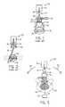
- FIG. 4is a perspective view of a ion therapy machine incorporating the elements of FIG. 3 providing constrained rotation of the fan beam;
- FIG. 5is a cross-section taken along line 5 - 5 of FIG. 4 showing the range of motion of a center axis of the fan beam in the present invention with respect to stationary neutron shield;
- FIG. 6is a top plan view in phantom of the system of FIG. 5 showing positioning of a patient to be pre-scanned with a tomography ring and then treated using the present invention
- FIGS. 7 a and 7 bare simplified representations of cross-sectional dose patterns for treatment of a tumor generated with a 360° scan and generated with a 150° scan per one embodiment of the present invention showing the latter scan's superior protection of sensitive distal tissue;
- FIG. 8is a perspective view of a “semi-helical” scanning pattern that may be implemented with the present invention.
- FIG. 9is a top plan view of the helical scan of FIG. 8 showing overlap of the scans that provides for “re-painting” reducing hot spots/cold spots;
- FIG. 10is a figure similar to that of FIG. 9 showing an alternative rectilinear scan system
- FIG. 11is a figure similar to that of FIGS. 9 and 10 showing an alternative rectilinear scan that may be superior for motion gating;
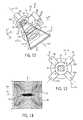
- FIG. 12is a perspective view of a magnetic beam former using two sequential and aligned quadrupole magnet systems and showing a mechanism for adjusting the separation of those magnet systems to adjust the resulting fan beam;
- FIG. 13is a simplified cross-sectional view along 13 - 13 through one quadrupole magnet of FIG. 12 showing the magnet orientations;
- FIG. 14is a magnetic field map of the quadrupole of FIG. 13 ;
- FIG. 15is an aligned top plan and side elevation view of the beam of FIG. 12 showing the effective operation of the quadrupole magnets as both converging and diverging lenses in different axes;
- FIG. 16is a perspective view of the elements of FIG. 3 showing the two quadrupole magnets and a binary shutter system that may be used to generate and modulate the fan beam in the present invention
- FIG. 17is a side view of the binary shutter system showing a side-by-side arrangement of arrays of attenuation elements providing shutters;
- FIG. 18is a side elevational view of one attenuation element showing its actuator for moving the attenuation element between a retracted position outside of the beam and an extended position within the beam;
- FIG. 19is a simplified representation of one array of binary-weighted attenuation elements fully extended to block the beam
- FIG. 20is a figure similar to that of FIG. 19 showing selected retraction of the attenuation elements such as it may provide controlled energy reduction in the beam;
- FIG. 21is an alternative embodiment showing the use of two modulation systems face to face to provide for two independently modulated adjacent fan beams.
- a conventional ion radiation therapy system 10employing the SOBP approach described above provides an ion source 12 producing a pencil beam 14 of ions traveling along an axis 20 .
- the pencil beam 14may be received by a foil 17 scattering the pencil beam into a cone beam 18 having a circular cross-section 21 .
- the energy of the ions in the cone beam 18is then received by a rotating wedge propeller placing a material of varying thickness in the cone beam 18 and acting as a range shifter 16 continuously changing the energy and thus range of penetration ions into tissue.
- the cone beam 18then passes through a collimator 24 approximating the outline of the tumor and a compensator 22 tailor-made for the particular tumor being treated after which the cone beam 18 is received by the patient 26 to produce a treatment pattern 28 .
- this treatment approachsimultaneously treats the entire volume of the tumor and is therefore relatively quick, but requires custom built collimators 24 and compensators 22 and also produces a treatment pattern 28 with imperfect conformance to an arbitrary tumor volume.
- a radiation therapy system 10 ′ for implementing the MSS approach, described abovereceives a pencil beam 14 from an ion source 12 and passes it through a range shifter 16 , for example, a set of movable plastic blocks of different thicknesses.
- the range shifted pencil beam 14passes next to a magnetic steering yoke 19 which steers the pencil beam 14 to different spots 30 within the patient 26 . Multiple spots 30 together create the treatment pattern 28 .
- This systemproduces good conformance of the treatment pattern 28 to an arbitrary tumor, but the sequential process is slow.
- the radiation therapy system 10 ′′ of the present inventionemploys an ion source 12 producing a pencil beam 14 .
- the pencil beam 14is received by a magnetic beam former 32 converting the pencil beam 14 into a fan beam 34 by magnetic deflection rather than scattering and thus minimizing the generation of neutrons.
- the fan beam 34is next received by a binary shutter system 36 which individually modulates the range and the intensity of the individual beamlets 38 of the fan beam 34 , the beamlets 38 being adjacent sectors of that fan beam 34 .
- the modulated fan beam 34may be moved in a partial arc 40 with respect to the patient 26 to provide for complex treatment patterns 28 taking advantage both of multiple angles of treatment and the ability to individually control the intensity and range of the beamlets 38 .
- the structure of the radiation therapy system 10 ′′may provide, for example, an axial proton beam conduit 42 receiving the pencil beam 14 of protons, for example, from a remote cyclotron or synchrotron (not shown).
- Beam steering magnets of a type well known in the artmay bend to the pencil beam 14 to follow a “crank arm” path of a gantry 44 having a radially extending segment 47 passing on a line of radius from an axis 46 of the entering pencil beam 14 and an axial segment 48 parallel to the axis 46 but spaced from the axis 46 as attached to the end of the radially extending segment 47 .
- the distal end of the axial segment 48holds a gantry head 50 (whose elements are shown generally in FIG. 3 ) and which directs a fan beam 34 toward a patient support 52 , the latter generally aligned with the axis 46 .
- the fan beam 34lies generally within a plane of rotation 54 of the gantry head 50 as the gantry head 50 moves about the patient support 52 .
- constant field bending magnets within the gantry 44may channel the pencil beam 14 to the gantry head 50 at any of its angular positions.
- the gantry head 50may rotate in an arc 56 about the axis 46 by an amount substantially less than 180° and in the preferred embodiment approximately 150°. As will be described further below, the present inventors have determined that this limited rotation, un-intuitively, can provide a superior dose pattern 28 when compared to a more complete 360° rotational of the gantry head 50 , such as would be preferred for intensity modulated radiation therapy using photons.
- the limited range of arc 56allows a massive stationary neutron stop 58 to be placed under the patient support 52 to receive neutrons generated by interaction of the ions with the patient 26 over the full range of arc 56 .
- the ability to use a stationary neutron stop 58allows the neutron stop 58 to be larger and closer to the patient 26 , allowing, for example, a form in-place concrete neutron shield.
- the stationary neutron stop 58may be supplemented with a movable neutron stop 23 mounted to an extension on the gantry 44 (not shown) to move therewith in opposition to the ion source 12 .
- This movable neutron stop 23may provide a counterweight for the gantry 44 and may reduce the size of the stationary neutron stop 58 .
- an x-ray tomography ring 60may be placed adjacent to the neutron stop 58 along the axis 46 so as to provide for planning tomographic images of the patient 26 contemporaneous with the radiation treatment.
- the displacement of the x-ray tomography ring 60 from the plane of rotation 54allows a full 360° of access to the patient (generally required of an x-ray tomography machine) for supporting both the detector and opposed x-ray source on opposite sides of the patient.
- a simplified treatment planmay be developed to treat a tumor 62 in the patient 26 having circular cross-section.
- Such a plan implemented with ion beam exposure over 360°provides a central region 64 of a dose pattern 28 having a high dose value resulting from aligned Bragg peaks 67 of ion beams entering the patient 26 over a range of angles of 360° about the patient.
- This central region 64is surrounded by a fringe 68 resulting from a reduced but measurable entrance dose of these proton beams.
- This fringe 68can be problematic if there is radiation sensitive tissue 70 , as is often the case, directly adjacent to the tumor 62 .
- a constrained rotation of the gantry head 50 and hence the fan beam 34can substantially limit the fringe 68 while preserving good conformity between the central region 64 and the tumor 62 .
- the ability to stop the ions within the tissue at the Bragg peak 67can wholly spare the radiation sensitive tissue 70 .
- the present inventorshave determined that the limitation of the arc 56 to as little as 150° still provides close conformance of the shape of central region 64 to the tumor 62 and minimization of hot/cold spots.
- the limited width of the fan beam along axes 46makes it desirable to translate the patient support 52 along axes 46 with respect to the gantry head 50 in order to obtain treatment volumes matching the longitudinal extent of the tumor while still preserving good spatial resolution determined by the thickness of the fan beam.
- the tablemay be translated by a table translation mechanism 61 such as a motorized carriage moving the patient support 52 or the gantry head 50 or both.
- the translation of the patient support 52may be continuous as the gantry head 50 rocks back and forth over the treatment arc 56 in a so-called “semi-helical” scan pattern such as traces a sawtooth raster 66 along axes 46 on an imaginary cylinder 69 surrounding the axis 46 .
- a sweeping of the cross-sectional area 71 of the fan beam 34 in this semi-helical scan patternmay be given a “pitch” by changing the relative speed of movement of the patient support 52 with respect to the speed of movement of the gantry head 50 in each cycle of reciprocation.
- the pitchdetermines the degree of overlap between successive sweep paths 72 of the sawtooth raster 66 moving cross-sectional area 71 , such overlap serving to reduce hotspots.
- the pitch shown hereis greatly exaggerated and, in practice, would be reduced to a fraction of the width of the cross-sectional area 71 along axes 46 .
- the scanning of the cross-sectional area 71serves also to eliminate inhomogeneities in the treatment caused by gaps between shutters used to modulate the beamlets 38 as will be described below.
- a rectilinear raster 66 ′may be adopted where the gantry head 50 is allowed to complete one half of a cycle of its reciprocation about axis 46 and then is stopped at the limits of the arc 56 to allow translation of the patient 26 along axes 46 . When movement of the patient 26 is complete the next cycle of reciprocation along arc 56 is performed.
- motion gatingmay be incorporated into the radiation therapy system 10 ′′ of the present invention in which a sensor system 73 senses movement of the patient 26 or internal organs of the patient 26 (for example, using ECG or respiration signals) to turn the fan beam 34 from the gantry head 50 on and off to treat the patient 26 at a constant phase of periodic motion.
- This gating processmay be improved with a rectilinear raster 66 ′′ shown in FIG. 11 , essentially rotating the rectilinear scanning pattern of FIG. 10 so that a full range of translation of the patient support 52 is completed before moving the gantry head 50 incrementally along arc 56 .
- the magnetic beam former 32in a preferred embodiment may comprise two quadrupole magnet assemblies 74 and 76 receiving the pencil beam 14 (as delivered to the gantry head 50 along gantry 44 ).
- the pencil beam 14is first received by a first quadrupole magnet assembly 74 and then received by the second quadrupole magnet assembly 76 downstream from the first quadrupole magnet assembly 74 .
- Both quadrupole magnet assemblies 74 and 76include apertures 78 coaxially aligned along a center axis 20 of the pencil beam 14 and the fan beam 34 .
- quadrupole magnets of the type used in quadrupole magnet assemblies 74 and 76are well known in the fields of high-energy accelerator physics and electron microscopy where quadrupole magnets with relative rotations of 90° about the axis of the beam are used to help refocus a pencil beam 14 to maintain its narrow cross-section.
- Each quadrupole magnet assembly 74 and 76comprises two pairs of magnets: a first pair 82 a and 82 b opposed across the aperture 78 along axes 79 with facing north poles, and a second pair 84 a and 84 b opposed across the aperture 78 along axes 79 ′ perpendicular to axes 79 .
- the magnetsmay be permanent magnets or preferably electromagnets so that the field strengths may be varied to allow the width and intensity profiles of the resultant fan beam 34 to be varied in both the convergent and divergent planes.
- two quadrupole magnet assemblies 74 and 76are aligned with respect to each other so that axes 79 ′ of quadrupole magnet assembly 74 lies in the same plane as axes 79 ′ of quadrupole magnet assembly 76 (this plane also including axis 46 ) and so that axes 79 of quadrupole magnet assembly 74 lies in the same plane as axes 79 of quadrupole magnet assembly 76 .
- the quadrupole magnet assemblies 74 and 76produce a magnetic field 86 that tends to widen a cross-section 35 of the fan beam 34 along the plane of rotation 54 and compress it in a z-direction normal to the plane of rotation 54 .
- quadrupole magnet assemblies 74 and 76act like diverging lenses when viewed in the plane of rotation 54 and converging lenses when viewed across the plane of rotation 54 . Because the forming of the pencil beam 14 into a fan beam 34 is done without scattering in a solid material, the production of neutrons is largely eliminated.
- the quadrupole magnet assemblies 74 and 76may be connected by controllable actuator mechanism 88 (such as a motor and rack and pinion mechanism) that may separate each of the quadrupole magnet assemblies 74 and 76 along the axis 20 according to an electrical signal and/or by mechanical adjustment.
- This controllable separationallows adjustment of the cross-sectional dimensions of the fan beam 34 to reduce collimation that also produces neutrons.
- the ability to change the cross-sectional dimensions of the fan beam 34 without collimationfurther allows for better utilization of the fan beam energy.
- the adjustment of the fan beam sizemay also be used for dynamic change of the beamlets 38 during treatment.
- the pencil beam 14ultimately received by the magnetic beam former 32 (composed of quadrupole magnet assemblies 74 and 76 ) may first pass through an emergency beam stop 80 and an entrance dose monitor 81 of conventional design, the latter measuring the energy of the beam 14 .
- a pencil beam aperture collimator 83may then shape the pencil beam 14 into a predictable cross-section for receipt by quadrupole magnet assembly 74 .
- the fan beam 34may pass through a segmented monitor measuring an energy or intensity profile of the beam 34 that may be used to further correct the energy profile of the fan beam 34 (by compensation using the binary shutter system 36 as will be described) or to correct a cross-section of the fan beam 34 , for example by controlling the field strengths of electromagnets of the quadrupole magnet assemblies 74 and 76 .
- the fan beam 34is then received by a set of collimator blocks 87 sharpening the edges of the fan beam to conform with a binary shutter system 36 as will be described below.
- the binary shutter system 36may provide a set of attenuating arrays 90 each aligned with a separate beamlet 38 of the fan beam 34 .
- Each attenuating array 90may be composed of a set of attenuating elements 92 (blade) each attenuating element 92 of a single array 90 being aligned with a particular beamlet 38 .
- Multiple arrays 90are placed side by side to span the width of the fan beam 34 so that each beamlet 38 may be controlled independently by a different array 90 .
- each attenuating element 92comprises blade 94 of an energy absorbing material having a thickness 93 approximating the angular width of a beamlet within the plane of rotation 54 and a variable length 95 that will differ for different blades 94 as will be described.
- the blade 94is attached to an actuator 96 that may move the blade 94 up and down along the y-axis generally perpendicular to the central axis 20 of the fan beam 34 .
- the blade 94may be moved between two positions, one within the path of the fan beam 34 and the other completely removed from the path of the fan beam 34 .
- the actuator 96may be extremely simple, for example, a pneumatic piston and cylinder (controlled by fluid pressure controlled in turn by a valve mechanism not shown) or electrical solenoid directly controlled by an electrical circuit.
- a single array 90may, for example, contain eight attenuating elements 92 having blades 94 a - 94 h .
- the length 95 of each blade 94 a - 94 h along axis 20may be according to a binary power series so, for example, blade 94 a through 94 h will have relative lengths 95 corresponding to successive terms in a binary power sequence (e.g.: 1, 2, 4, 8, 16 etc.).
- blade 94 dmay be eight times as thick as the thinnest blade 94 a . In this way, as shown in FIG.
- any one of 256 equal increments of attenuationmay be obtained by drawing some of the blades 94 out of the beam 34 and placing some of the blades 94 into the beam.
- a relative attenuation of 43may be obtained consisting of the combined blades 94 d , 94 a , 94 b , and 94 f (having attenuation's 8, 1, 2, and 32 respectively where 1 is the attenuation provided by the thinnest blade 94 a ).
- This “binary” sequencemust be distinguished from the “binary” action of the shutters and a binary sequence need not be used for the binary shutter system 36 as will be described below.
- This binary power seriesprovides the simplest blade structure and actuation mechanisms but it will be understood that other power series can also be used and in fact the variations in attenuations among blades 94 need not conform to a power series but, for example, may conform to other series and may include duplicate blades 94 of a single attenuation, for example to operate at higher speed or distribute wear.
- the blades 94may have the relative lengths 95 of 1, 1, 3, 6, 9, 18, etc.
- blades 94 positionable in any of three (or more) positions with respect to the fan beam 34could be used providing attenuations in the series (0, 1, 2), (0, 3, 9), (0, 9, 18), (0, 27, 54) . . . .
- Attenuating elements 92need not be constructed of a uniform material in which their length 95 corresponds to attenuation, but may be constructed of different materials having different densities to minimize their differences in length 95 for mechanical or structural reasons.
- the order of the blades 94 in the fan beam 34need not conform to their relative ranking in attenuation, and in fact in the preferred embodiment this order is buried so as to provide for suitable clearance for the attached actuators 96 .
- the combination of all attenuating elements 92completely stops the fan beam 34 , and thus a proper selection of different attenuating elements 92 (short of blocking the fan beam 34 ) may be used to control range shifting of ions of the fan beam 34 , while a selection of all attenuating elements 92 (fully blocking the fan beam 34 ) may be used to control the intensity of the beam through duty-cycle modulation so that both range and intensity may be controlled with the modulator 36 .
- a separate blocking element(not shown) for each beamlet 38 may be used to provide this intensity modulation.
- the intensity modulation or range shifting effected by the binary shutter system 36may be augmented by other mechanisms applied to some or all of the beamlets 38 , for example those correcting the profile of the fan beam 34 or serving to offset the range shifting of all the beamlets 38 based on patient size.
- the control of the individual blades 94may be performed, for example, so that all of the attenuating blades 94 do not move simultaneously but are rather staggered to ensure the minimum deviation in range shifting during the transition of the blades 94 .
- the movement of blades 94 providing greater attenuationmay be alternated with movement of blades 94 providing less attenuation to reduce variations in range shifting.
- two binary shutter systems 36 and 36 ′may be opposed about the fan beam 34 effectively dividing the fan beam 34 along an x-y plane (parallel to the plane of rotation 54 ) into two separately modulated fan beams 34 and 34 ′ effectively allowing multi-slice treatment of the patient improving the speed/resolution trade-off of the treatment system.
- the geometry of the actuators 96 and blades 94allows all of the actuators 96 to be fully displaced out of the area of the beam 34 .
- the binary shutter system 36may also be used for photon modulation; the term “radiation” as used herein will include generally both photons and particles serving for treatment of tissue.
- an electronic computer 100 executing a stored programmay be associated with the radiation therapy system 10 ′′ executing a radiation treatment plan that coordinates and controls all of the electrically controllable elements described above including but not limited to the binary shutter system 36 , the magnetic beam former 32 (including magnetic field strength of the magnets and their separation) and the movement of the gantry 44 and patient support 52 as well as receipt and control of the x-ray tomography ring 60 .
- This controlmay be done according to a stored radiation treatment plan, and in light of signals obtained from monitors 81 and 85 .
- Data collected by the computer 100then provide images for the assessment of the treatment plan, as well as input to feedback loops confirming the proper operation of the system according to techniques known in the art of intensity modulated radiation therapy.
- the range and intensity of individual beamlets 38will be modulated according to a treatment plan stored in the computer 100 and typically determined by a health care professional using an image of the tumor using the tomography ring 60 . Determination of the proper modulation of the beamlets 38 may be done by techniques analogous to those used with prior art intensity modulated radiation therapy adapted to the unique properties of ion beams. These techniques include for example Simulated Annealing and gradient based optimization techniques.
- the present inventionhas been described in terms of the preferred embodiment, and it is recognized that equivalents, alternatives, and modifications, aside from those expressly stated, are possible and within the scope of the appending claims.
Landscapes
- Health & Medical Sciences (AREA)
- Engineering & Computer Science (AREA)
- Biomedical Technology (AREA)
- Pathology (AREA)
- Nuclear Medicine, Radiotherapy & Molecular Imaging (AREA)
- Radiology & Medical Imaging (AREA)
- Life Sciences & Earth Sciences (AREA)
- Animal Behavior & Ethology (AREA)
- General Health & Medical Sciences (AREA)
- Public Health (AREA)
- Veterinary Medicine (AREA)
- Radiation-Therapy Devices (AREA)
Abstract
Description
Claims (2)
Priority Applications (1)
| Application Number | Priority Date | Filing Date | Title |
|---|---|---|---|
| US12/438,255US8093568B2 (en) | 2007-02-27 | 2008-02-27 | Ion radiation therapy system with rocking gantry motion |
Applications Claiming Priority (3)
| Application Number | Priority Date | Filing Date | Title |
|---|---|---|---|
| US89185907P | 2007-02-27 | 2007-02-27 | |
| PCT/US2008/055070WO2008106484A1 (en) | 2007-02-27 | 2008-02-27 | Ion radiation therapy system with rocking gantry motion |
| US12/438,255US8093568B2 (en) | 2007-02-27 | 2008-02-27 | Ion radiation therapy system with rocking gantry motion |
Publications (2)
| Publication Number | Publication Date |
|---|---|
| US20100176309A1 US20100176309A1 (en) | 2010-07-15 |
| US8093568B2true US8093568B2 (en) | 2012-01-10 |
Family
ID=40451383
Family Applications (1)
| Application Number | Title | Priority Date | Filing Date |
|---|---|---|---|
| US12/438,255Active2028-11-15US8093568B2 (en) | 2007-02-27 | 2008-02-27 | Ion radiation therapy system with rocking gantry motion |
Country Status (2)
| Country | Link |
|---|---|
| US (1) | US8093568B2 (en) |
| WO (1) | WO2008106484A1 (en) |
Cited By (38)
| Publication number | Priority date | Publication date | Assignee | Title |
|---|---|---|---|---|
| US20100045213A1 (en)* | 2004-07-21 | 2010-02-25 | Still River Systems, Inc. | Programmable Radio Frequency Waveform Generator for a Synchrocyclotron |
| US8791656B1 (en)* | 2013-05-31 | 2014-07-29 | Mevion Medical Systems, Inc. | Active return system |
| US8907311B2 (en) | 2005-11-18 | 2014-12-09 | Mevion Medical Systems, Inc. | Charged particle radiation therapy |
| US8927950B2 (en) | 2012-09-28 | 2015-01-06 | Mevion Medical Systems, Inc. | Focusing a particle beam |
| US8933650B2 (en) | 2007-11-30 | 2015-01-13 | Mevion Medical Systems, Inc. | Matching a resonant frequency of a resonant cavity to a frequency of an input voltage |
| US8941083B2 (en) | 2007-10-11 | 2015-01-27 | Mevion Medical Systems, Inc. | Applying a particle beam to a patient |
| US8970137B2 (en) | 2007-11-30 | 2015-03-03 | Mevion Medical Systems, Inc. | Interrupted particle source |
| US9155186B2 (en) | 2012-09-28 | 2015-10-06 | Mevion Medical Systems, Inc. | Focusing a particle beam using magnetic field flutter |
| US9185789B2 (en) | 2012-09-28 | 2015-11-10 | Mevion Medical Systems, Inc. | Magnetic shims to alter magnetic fields |
| US9301384B2 (en) | 2012-09-28 | 2016-03-29 | Mevion Medical Systems, Inc. | Adjusting energy of a particle beam |
| US9545528B2 (en) | 2012-09-28 | 2017-01-17 | Mevion Medical Systems, Inc. | Controlling particle therapy |
| US9622335B2 (en) | 2012-09-28 | 2017-04-11 | Mevion Medical Systems, Inc. | Magnetic field regenerator |
| US9661736B2 (en) | 2014-02-20 | 2017-05-23 | Mevion Medical Systems, Inc. | Scanning system for a particle therapy system |
| US9681531B2 (en) | 2012-09-28 | 2017-06-13 | Mevion Medical Systems, Inc. | Control system for a particle accelerator |
| US9723705B2 (en) | 2012-09-28 | 2017-08-01 | Mevion Medical Systems, Inc. | Controlling intensity of a particle beam |
| US9730308B2 (en) | 2013-06-12 | 2017-08-08 | Mevion Medical Systems, Inc. | Particle accelerator that produces charged particles having variable energies |
| US20180001112A1 (en)* | 2015-05-04 | 2018-01-04 | Neuboron Medtech Ltd. | Beam shaping assembly for neutron capture therapy |
| US9950194B2 (en) | 2014-09-09 | 2018-04-24 | Mevion Medical Systems, Inc. | Patient positioning system |
| US9962560B2 (en) | 2013-12-20 | 2018-05-08 | Mevion Medical Systems, Inc. | Collimator and energy degrader |
| US10254739B2 (en) | 2012-09-28 | 2019-04-09 | Mevion Medical Systems, Inc. | Coil positioning system |
| US10258810B2 (en) | 2013-09-27 | 2019-04-16 | Mevion Medical Systems, Inc. | Particle beam scanning |
| US10646728B2 (en) | 2015-11-10 | 2020-05-12 | Mevion Medical Systems, Inc. | Adaptive aperture |
| US10653892B2 (en) | 2017-06-30 | 2020-05-19 | Mevion Medical Systems, Inc. | Configurable collimator controlled using linear motors |
| US10675487B2 (en) | 2013-12-20 | 2020-06-09 | Mevion Medical Systems, Inc. | Energy degrader enabling high-speed energy switching |
| WO2020219071A1 (en)* | 2019-04-26 | 2020-10-29 | Elekta, Inc. | A method of providing proton radiation therapy utilizing periodic motion |
| US10925147B2 (en) | 2016-07-08 | 2021-02-16 | Mevion Medical Systems, Inc. | Treatment planning |
| US10959686B2 (en)* | 2008-03-14 | 2021-03-30 | Reflexion Medical, Inc. | Method and apparatus for emission guided radiation therapy |
| US11103730B2 (en) | 2017-02-23 | 2021-08-31 | Mevion Medical Systems, Inc. | Automated treatment in particle therapy |
| US11141607B2 (en) | 2011-03-31 | 2021-10-12 | Reflexion Medical, Inc. | Systems and methods for use in emission guided radiation therapy |
| US20220023664A1 (en)* | 2018-12-20 | 2022-01-27 | Raysearch Laboratories Ab | System and method for planning of passive ion radiotherapy treatment |
| US11287540B2 (en) | 2017-07-11 | 2022-03-29 | Reflexion Medical, Inc. | Methods for PET detector afterglow management |
| US11291861B2 (en) | 2019-03-08 | 2022-04-05 | Mevion Medical Systems, Inc. | Delivery of radiation by column and generating a treatment plan therefor |
| US11369806B2 (en) | 2017-11-14 | 2022-06-28 | Reflexion Medical, Inc. | Systems and methods for patient monitoring for radiotherapy |
| US11511133B2 (en) | 2017-08-09 | 2022-11-29 | Reflexion Medical, Inc. | Systems and methods for fault detection in emission-guided radiotherapy |
| US11904184B2 (en) | 2017-03-30 | 2024-02-20 | Reflexion Medical, Inc. | Radiation therapy systems and methods with tumor tracking |
| US11975220B2 (en) | 2016-11-15 | 2024-05-07 | Reflexion Medical, Inc. | System for emission-guided high-energy photon delivery |
| US12245355B2 (en) | 2021-02-19 | 2025-03-04 | Mevion Medical Systems, Inc. | Gantry for a particle therapy system |
| US12251579B2 (en) | 2020-08-07 | 2025-03-18 | Reflexion Medical, Inc. | Multi-sensor guided radiation therapy |
Families Citing this family (24)
| Publication number | Priority date | Publication date | Assignee | Title |
|---|---|---|---|---|
| WO2009035080A1 (en)* | 2007-09-12 | 2009-03-19 | Kabushiki Kaisha Toshiba | Particle beam projection apparatus and particle beam projection method |
| US8896239B2 (en) | 2008-05-22 | 2014-11-25 | Vladimir Yegorovich Balakin | Charged particle beam injection method and apparatus used in conjunction with a charged particle cancer therapy system |
| WO2009142546A2 (en) | 2008-05-22 | 2009-11-26 | Vladimir Yegorovich Balakin | Multi-field charged particle cancer therapy method and apparatus |
| CA2725493C (en) | 2008-05-22 | 2015-08-18 | Vladimir Yegorovich Balakin | Charged particle cancer therapy beam path control method and apparatus |
| US8688197B2 (en)* | 2008-05-22 | 2014-04-01 | Vladimir Yegorovich Balakin | Charged particle cancer therapy patient positioning method and apparatus |
| WO2009142549A2 (en) | 2008-05-22 | 2009-11-26 | Vladimir Yegorovich Balakin | Multi-axis charged particle cancer therapy method and apparatus |
| JP2011523169A (en) | 2008-05-22 | 2011-08-04 | エゴロヴィチ バラキン、ウラジミール | Charged particle beam extraction method and apparatus for use with a charged particle cancer treatment system |
| WO2009142548A2 (en)* | 2008-05-22 | 2009-11-26 | Vladimir Yegorovich Balakin | X-ray method and apparatus used in conjunction with a charged particle cancer therapy system |
| EP2283711B1 (en) | 2008-05-22 | 2018-07-11 | Vladimir Yegorovich Balakin | Charged particle beam acceleration apparatus as part of a charged particle cancer therapy system |
| BRPI0924903B8 (en) | 2009-03-04 | 2021-06-22 | Zakrytoe Aktsionernoe Obshchestvo Protom | apparatus for generating a negative ion beam for use in charged particle radiation therapy and method for generating a negative ion beam for use with charged particle radiation therapy |
| JP5372178B2 (en)* | 2009-12-25 | 2013-12-18 | 株式会社Ihi | Drug delivery control device |
| US8934605B2 (en) | 2010-02-24 | 2015-01-13 | Accuray Incorporated | Gantry image guided radiotherapy system and related treatment delivery methods |
| US9687200B2 (en)* | 2010-06-08 | 2017-06-27 | Accuray Incorporated | Radiation treatment delivery system with translatable ring gantry |
| US10188877B2 (en)* | 2010-04-16 | 2019-01-29 | W. Davis Lee | Fiducial marker/cancer imaging and treatment apparatus and method of use thereof |
| ES1073912Y (en)* | 2010-10-14 | 2011-10-04 | Pellicer Carlos F | MEDICAL EQUIPMENT |
| US8536547B2 (en)* | 2011-01-20 | 2013-09-17 | Accuray Incorporated | Ring gantry radiation treatment delivery system with dynamically controllable inward extension of treatment head |
| US20120330084A1 (en)* | 2011-06-27 | 2012-12-27 | Richard Harris Pantell | Neutron Source for Neutron Capture Therapy |
| EP2647407A1 (en)* | 2012-04-03 | 2013-10-09 | Paul Scherrer Institut | A system for the delivery of proton therapy by pencil beam scanning of a predeterminable volume within a patient |
| US9833636B2 (en)* | 2012-09-13 | 2017-12-05 | Varian Medical Systems, Inc. | Multi-axis dynamic tracking for radiation therapy |
| US20170281979A1 (en)* | 2016-03-31 | 2017-10-05 | Varian Medical Systems International Ag | Radiation Treatment Platform and Method Using a Portal Imaging Device to Automatically Control Therapy Administration |
| WO2018093849A1 (en) | 2016-11-15 | 2018-05-24 | Reflexion Medical, Inc. | Methods for radiation delivery in emission-guided radiotherapy |
| CN110382050B (en)* | 2017-01-05 | 2022-04-12 | 梅维昂医疗系统股份有限公司 | a particle therapy system |
| WO2019160958A1 (en) | 2018-02-13 | 2019-08-22 | Reflexion Medical, Inc. | Beam station treatment planning and radiation delivery methods |
| US10946220B2 (en)* | 2019-03-01 | 2021-03-16 | Elekta, Inc. | Method of providing rotational radiation therapy using particles |
Citations (52)
| Publication number | Priority date | Publication date | Assignee | Title |
|---|---|---|---|---|
| US4276477A (en)* | 1979-09-17 | 1981-06-30 | Varian Associates, Inc. | Focusing apparatus for uniform application of charged particle beam |
| US5317616A (en) | 1992-03-19 | 1994-05-31 | Wisconsin Alumni Research Foundation | Method and apparatus for radiation therapy |
| US5394452A (en) | 1992-03-19 | 1995-02-28 | Wisconsin Alumni Research Foundation | Verification system for radiation therapy |
| US5625663A (en) | 1992-03-19 | 1997-04-29 | Wisconsin Alumni Research Foundation | Dynamic beam flattening apparatus for radiation therapy |
| US5661773A (en) | 1992-03-19 | 1997-08-26 | Wisconsin Alumni Research Foundation | Interface for radiation therapy machine |
| US5668371A (en)* | 1995-06-06 | 1997-09-16 | Wisconsin Alumni Research Foundation | Method and apparatus for proton therapy |
| US5673300A (en) | 1996-06-11 | 1997-09-30 | Wisconsin Alumni Research Foundation | Method of registering a radiation treatment plan to a patient |
| US5724400A (en) | 1992-03-19 | 1998-03-03 | Wisconsin Alumni Research Foundation | Radiation therapy system with constrained rotational freedom |
| US5802136A (en) | 1994-05-17 | 1998-09-01 | Nomos Corporation | Method and apparatus for conformal radiation therapy |
| EP0986070A1 (en) | 1998-09-11 | 2000-03-15 | Gesellschaft für Schwerionenforschung mbH | Ion beam therapy system and a method for operating the system |
| JP2000214298A (en) | 1999-01-20 | 2000-08-04 | Mitsubishi Electric Corp | Charged particle beam irradiation apparatus, energy compensator used in the apparatus, and charged particle beam irradiation method |
| DE19907098A1 (en) | 1999-02-19 | 2000-08-24 | Schwerionenforsch Gmbh | Ion beam scanning system for radiation therapy e.g. for tumor treatment, uses energy absorption device displaced transverse to ion beam path via linear motor for altering penetration depth |
| EP1045399A1 (en) | 1999-04-12 | 2000-10-18 | GSI Gesellschaft für Schwerionenforschung mbH | Device and method for controlling a raster scanner in ion theraphy |
| WO2002007817A2 (en) | 2000-06-30 | 2002-01-31 | Gesellschaft für Schwerionenforschung mbH | Device for irradiating a tumor tissue |
| US6345114B1 (en) | 1995-06-14 | 2002-02-05 | Wisconsin Alumni Research Foundation | Method and apparatus for calibration of radiation therapy equipment and verification of radiation treatment |
| US6385286B1 (en) | 1998-08-06 | 2002-05-07 | Wisconsin Alumni Research Foundation | Delivery modification system for radiation therapy |
| WO2002041948A1 (en) | 2000-11-21 | 2002-05-30 | Gesellschaft für Schwerionenforschung mbH | Device and method for adapting the size of an ion beam spot in the domain of tumor irradiation |
| US6438202B1 (en) | 1998-08-06 | 2002-08-20 | Wisconsin Alumni Research Foundation | Method using post-patient radiation monitor to verify entrance radiation and dose in a radiation therapy machine |
| US20020136439A1 (en) | 2001-03-09 | 2002-09-26 | Ruchala Kenneth J. | System and method for fusion-aligned reprojection of incomplete data |
| US6560311B1 (en) | 1998-08-06 | 2003-05-06 | Wisconsin Alumni Research Foundation | Method for preparing a radiation therapy plan |
| US20030160189A1 (en)* | 2002-02-28 | 2003-08-28 | Koji Matsuda | Charged particle beam irradiation apparatus |
| US6618467B1 (en) | 1999-04-02 | 2003-09-09 | Wisconsin Alumni Research Foundation | Megavoltage computed tomography during radiotherapy |
| US6636622B2 (en) | 1997-10-15 | 2003-10-21 | Wisconsin Alumni Research Foundation | Method and apparatus for calibration of radiation therapy equipment and verification of radiation treatment |
| US20030198319A1 (en)* | 2002-04-22 | 2003-10-23 | Toth Thomas L. | Method and apparatus of modulating the filtering of radiation during radiographic imaging |
| US6661870B2 (en) | 2001-03-09 | 2003-12-09 | Tomotherapy Incorporated | Fluence adjustment for improving delivery to voxels without reoptimization |
| US6731970B2 (en)* | 2000-07-07 | 2004-05-04 | Brainlab Ag | Method for breath compensation in radiation therapy |
| WO2005004168A1 (en) | 2003-07-01 | 2005-01-13 | National Institute Of Radiological Sciences | Range compensator and heavy charged particle beam irradiation system |
| US20050123092A1 (en) | 2001-12-14 | 2005-06-09 | Mistretta Charles A. | Virtual spherical anode computed tomography |
| US20050197564A1 (en)* | 2004-02-20 | 2005-09-08 | University Of Florida Research Foundation, Inc. | System for delivering conformal radiation therapy while simultaneously imaging soft tissue |
| US20060226372A1 (en)* | 2005-03-31 | 2006-10-12 | Masaki Yanagisawa | Charged particle beam extraction system and method |
| US20060285639A1 (en) | 2005-05-10 | 2006-12-21 | Tomotherapy Incorporated | System and method of treating a patient with radiation therapy |
| US20070029510A1 (en)* | 2005-08-05 | 2007-02-08 | Siemens Aktiengesellschaft | Gantry system for a particle therapy facility |
| US20070036267A1 (en) | 2005-07-22 | 2007-02-15 | Becker Stewart J | Low skin dose patient positioning device for radiation treatment of prone breast |
| US20070041495A1 (en) | 2005-07-22 | 2007-02-22 | Olivera Gustavo H | Method of and system for predicting dose delivery |
| US20070041497A1 (en) | 2005-07-22 | 2007-02-22 | Eric Schnarr | Method and system for processing data relating to a radiation therapy treatment plan |
| US20070041496A1 (en) | 2005-07-22 | 2007-02-22 | Olivera Gustavo H | System and method of remotely analyzing operation of a radiation therapy system |
| US20070043286A1 (en) | 2005-07-22 | 2007-02-22 | Weiguo Lu | Method and system for adapting a radiation therapy treatment plan based on a biological model |
| WO2007021226A1 (en) | 2005-08-16 | 2007-02-22 | C-Rad Innovation Ab | Radiation modulator |
| US20070041494A1 (en) | 2005-07-22 | 2007-02-22 | Ruchala Kenneth J | Method and system for evaluating delivered dose |
| US20070041500A1 (en) | 2005-07-23 | 2007-02-22 | Olivera Gustavo H | Radiation therapy imaging and delivery utilizing coordinated motion of gantry and couch |
| US20070041499A1 (en) | 2005-07-22 | 2007-02-22 | Weiguo Lu | Method and system for evaluating quality assurance criteria in delivery of a treatment plan |
| US7186986B2 (en) | 2001-06-18 | 2007-03-06 | Wisconsin Alumni Research Foundation | Radiation detector with converters |
| US20070076846A1 (en) | 2005-07-22 | 2007-04-05 | Ruchala Kenneth J | System and method of delivering radiation therapy to a moving region of interest |
| US7207715B2 (en) | 2005-07-29 | 2007-04-24 | Upmc | Method to implement full six-degree target shift corrections in radiotherapy |
| US20070195930A1 (en) | 2005-07-22 | 2007-08-23 | Kapatoes Jeffrey M | System and method of generating contour structures using a dose volume histogram |
| US20070195929A1 (en) | 2005-07-22 | 2007-08-23 | Ruchala Kenneth J | System and method of evaluating dose delivered by a radiation therapy system |
| US20070195922A1 (en) | 2005-07-22 | 2007-08-23 | Mackie Thomas R | System and method of monitoring the operation of a medical device |
| US20070242801A1 (en) | 2005-04-01 | 2007-10-18 | Wisconsin Alumni Research Foundation | Small Field Intensity Modulated Radiation Therapy Machine |
| US7302038B2 (en)* | 2004-09-24 | 2007-11-27 | Wisconsin Alumni Research Foundation | Correction of patient rotation errors in radiotherapy using couch translation |
| US20090200483A1 (en)* | 2005-11-18 | 2009-08-13 | Still River Systems Incorporated | Inner Gantry |
| US20100059687A1 (en)* | 2008-05-22 | 2010-03-11 | Vladimir Balakin | Proton beam positioning verification method and apparatus used in conjunction with a charged particle cancer therapy system |
| US20100266100A1 (en)* | 2008-05-22 | 2010-10-21 | Dr. Vladimir Balakin | Charged particle cancer therapy beam path control method and apparatus |
- 2008
- 2008-02-27USUS12/438,255patent/US8093568B2/enactiveActive
- 2008-02-27WOPCT/US2008/055070patent/WO2008106484A1/enactiveApplication Filing
Patent Citations (60)
| Publication number | Priority date | Publication date | Assignee | Title |
|---|---|---|---|---|
| US4276477A (en)* | 1979-09-17 | 1981-06-30 | Varian Associates, Inc. | Focusing apparatus for uniform application of charged particle beam |
| US5724400A (en) | 1992-03-19 | 1998-03-03 | Wisconsin Alumni Research Foundation | Radiation therapy system with constrained rotational freedom |
| US5317616A (en) | 1992-03-19 | 1994-05-31 | Wisconsin Alumni Research Foundation | Method and apparatus for radiation therapy |
| US5394452A (en) | 1992-03-19 | 1995-02-28 | Wisconsin Alumni Research Foundation | Verification system for radiation therapy |
| US5442675A (en) | 1992-03-19 | 1995-08-15 | Wisconsin Alumni Research Foundation | Dynamic collimator for radiation therapy |
| US5528650A (en) | 1992-03-19 | 1996-06-18 | Swerdloff; Stuart | Method and apparatus for radiation therapy |
| US5548627A (en) | 1992-03-19 | 1996-08-20 | Wisconsin Alumni Research Foundation | Radiation therapy system with constrained rotational freedom |
| US5625663A (en) | 1992-03-19 | 1997-04-29 | Wisconsin Alumni Research Foundation | Dynamic beam flattening apparatus for radiation therapy |
| US5661773A (en) | 1992-03-19 | 1997-08-26 | Wisconsin Alumni Research Foundation | Interface for radiation therapy machine |
| US5802136A (en) | 1994-05-17 | 1998-09-01 | Nomos Corporation | Method and apparatus for conformal radiation therapy |
| US5668371A (en)* | 1995-06-06 | 1997-09-16 | Wisconsin Alumni Research Foundation | Method and apparatus for proton therapy |
| US6345114B1 (en) | 1995-06-14 | 2002-02-05 | Wisconsin Alumni Research Foundation | Method and apparatus for calibration of radiation therapy equipment and verification of radiation treatment |
| US5673300A (en) | 1996-06-11 | 1997-09-30 | Wisconsin Alumni Research Foundation | Method of registering a radiation treatment plan to a patient |
| US6636622B2 (en) | 1997-10-15 | 2003-10-21 | Wisconsin Alumni Research Foundation | Method and apparatus for calibration of radiation therapy equipment and verification of radiation treatment |
| US6438202B1 (en) | 1998-08-06 | 2002-08-20 | Wisconsin Alumni Research Foundation | Method using post-patient radiation monitor to verify entrance radiation and dose in a radiation therapy machine |
| US6560311B1 (en) | 1998-08-06 | 2003-05-06 | Wisconsin Alumni Research Foundation | Method for preparing a radiation therapy plan |
| US6385286B1 (en) | 1998-08-06 | 2002-05-07 | Wisconsin Alumni Research Foundation | Delivery modification system for radiation therapy |
| EP0986070A1 (en) | 1998-09-11 | 2000-03-15 | Gesellschaft für Schwerionenforschung mbH | Ion beam therapy system and a method for operating the system |
| JP2000214298A (en) | 1999-01-20 | 2000-08-04 | Mitsubishi Electric Corp | Charged particle beam irradiation apparatus, energy compensator used in the apparatus, and charged particle beam irradiation method |
| DE19907098A1 (en) | 1999-02-19 | 2000-08-24 | Schwerionenforsch Gmbh | Ion beam scanning system for radiation therapy e.g. for tumor treatment, uses energy absorption device displaced transverse to ion beam path via linear motor for altering penetration depth |
| US6618467B1 (en) | 1999-04-02 | 2003-09-09 | Wisconsin Alumni Research Foundation | Megavoltage computed tomography during radiotherapy |
| EP1045399A1 (en) | 1999-04-12 | 2000-10-18 | GSI Gesellschaft für Schwerionenforschung mbH | Device and method for controlling a raster scanner in ion theraphy |
| WO2002007817A2 (en) | 2000-06-30 | 2002-01-31 | Gesellschaft für Schwerionenforschung mbH | Device for irradiating a tumor tissue |
| US6731970B2 (en)* | 2000-07-07 | 2004-05-04 | Brainlab Ag | Method for breath compensation in radiation therapy |
| WO2002041948A1 (en) | 2000-11-21 | 2002-05-30 | Gesellschaft für Schwerionenforschung mbH | Device and method for adapting the size of an ion beam spot in the domain of tumor irradiation |
| US20020136439A1 (en) | 2001-03-09 | 2002-09-26 | Ruchala Kenneth J. | System and method for fusion-aligned reprojection of incomplete data |
| US7046831B2 (en) | 2001-03-09 | 2006-05-16 | Tomotherapy Incorporated | System and method for fusion-aligned reprojection of incomplete data |
| US6661870B2 (en) | 2001-03-09 | 2003-12-09 | Tomotherapy Incorporated | Fluence adjustment for improving delivery to voxels without reoptimization |
| US6915005B1 (en) | 2001-03-09 | 2005-07-05 | Tomo Therapy Incorporated | Method for reconstruction of limited data images using fusion-aligned reprojection and normal-error-aligned reprojection |
| US7186986B2 (en) | 2001-06-18 | 2007-03-06 | Wisconsin Alumni Research Foundation | Radiation detector with converters |
| US20050123092A1 (en) | 2001-12-14 | 2005-06-09 | Mistretta Charles A. | Virtual spherical anode computed tomography |
| US20030160189A1 (en)* | 2002-02-28 | 2003-08-28 | Koji Matsuda | Charged particle beam irradiation apparatus |
| US20030198319A1 (en)* | 2002-04-22 | 2003-10-23 | Toth Thomas L. | Method and apparatus of modulating the filtering of radiation during radiographic imaging |
| WO2005004168A1 (en) | 2003-07-01 | 2005-01-13 | National Institute Of Radiological Sciences | Range compensator and heavy charged particle beam irradiation system |
| US20050197564A1 (en)* | 2004-02-20 | 2005-09-08 | University Of Florida Research Foundation, Inc. | System for delivering conformal radiation therapy while simultaneously imaging soft tissue |
| US7302038B2 (en)* | 2004-09-24 | 2007-11-27 | Wisconsin Alumni Research Foundation | Correction of patient rotation errors in radiotherapy using couch translation |
| US20060226372A1 (en)* | 2005-03-31 | 2006-10-12 | Masaki Yanagisawa | Charged particle beam extraction system and method |
| US20070242801A1 (en) | 2005-04-01 | 2007-10-18 | Wisconsin Alumni Research Foundation | Small Field Intensity Modulated Radiation Therapy Machine |
| US20060285639A1 (en) | 2005-05-10 | 2006-12-21 | Tomotherapy Incorporated | System and method of treating a patient with radiation therapy |
| US20070195929A1 (en) | 2005-07-22 | 2007-08-23 | Ruchala Kenneth J | System and method of evaluating dose delivered by a radiation therapy system |
| US20070041495A1 (en) | 2005-07-22 | 2007-02-22 | Olivera Gustavo H | Method of and system for predicting dose delivery |
| US20070043286A1 (en) | 2005-07-22 | 2007-02-22 | Weiguo Lu | Method and system for adapting a radiation therapy treatment plan based on a biological model |
| US20070036267A1 (en) | 2005-07-22 | 2007-02-15 | Becker Stewart J | Low skin dose patient positioning device for radiation treatment of prone breast |
| US20070041498A1 (en) | 2005-07-22 | 2007-02-22 | Olivera Gustavo H | System and method of remotely directing radiation therapy treatment |
| US20070041494A1 (en) | 2005-07-22 | 2007-02-22 | Ruchala Kenneth J | Method and system for evaluating delivered dose |
| US20070041496A1 (en) | 2005-07-22 | 2007-02-22 | Olivera Gustavo H | System and method of remotely analyzing operation of a radiation therapy system |
| US20070041499A1 (en) | 2005-07-22 | 2007-02-22 | Weiguo Lu | Method and system for evaluating quality assurance criteria in delivery of a treatment plan |
| US20070041497A1 (en) | 2005-07-22 | 2007-02-22 | Eric Schnarr | Method and system for processing data relating to a radiation therapy treatment plan |
| US20070076846A1 (en) | 2005-07-22 | 2007-04-05 | Ruchala Kenneth J | System and method of delivering radiation therapy to a moving region of interest |
| US20070195922A1 (en) | 2005-07-22 | 2007-08-23 | Mackie Thomas R | System and method of monitoring the operation of a medical device |
| US20070104316A1 (en) | 2005-07-22 | 2007-05-10 | Ruchala Kenneth J | System and method of recommending a location for radiation therapy treatment |
| US20070195930A1 (en) | 2005-07-22 | 2007-08-23 | Kapatoes Jeffrey M | System and method of generating contour structures using a dose volume histogram |
| US20070041500A1 (en) | 2005-07-23 | 2007-02-22 | Olivera Gustavo H | Radiation therapy imaging and delivery utilizing coordinated motion of gantry and couch |
| US7207715B2 (en) | 2005-07-29 | 2007-04-24 | Upmc | Method to implement full six-degree target shift corrections in radiotherapy |
| US20070029510A1 (en)* | 2005-08-05 | 2007-02-08 | Siemens Aktiengesellschaft | Gantry system for a particle therapy facility |
| WO2007021226A1 (en) | 2005-08-16 | 2007-02-22 | C-Rad Innovation Ab | Radiation modulator |
| US20090200483A1 (en)* | 2005-11-18 | 2009-08-13 | Still River Systems Incorporated | Inner Gantry |
| US7728311B2 (en)* | 2005-11-18 | 2010-06-01 | Still River Systems Incorporated | Charged particle radiation therapy |
| US20100059687A1 (en)* | 2008-05-22 | 2010-03-11 | Vladimir Balakin | Proton beam positioning verification method and apparatus used in conjunction with a charged particle cancer therapy system |
| US20100266100A1 (en)* | 2008-05-22 | 2010-10-21 | Dr. Vladimir Balakin | Charged particle cancer therapy beam path control method and apparatus |
Non-Patent Citations (26)
| Title |
|---|
| Anferov V., Combined X-Y scanning magnet for conformal proton radiation therapy, Med. Phys. , Mar. 2005, 32:815-818, American Association of Physical Medicine, New York, New York. |
| Baumert, BG, et al., Dose conformation of intensity-modulated stereotactic photon beams, proton beams, and intensity-modulated proton beams for intracranial lesions, Int. J. Radiat. Oncol. Biol. Phys., 2005, 60:1314-1324, Elsevier, Amsterdam, Netherlands. |
| Deasy, JO, A proton dose calculation algorithm for conformal therapy simulations based on Moliere theory of lateral deflections, Med. Phys., Apr. 1998, 25:476-483, American Association of Physical Medicine, New York, New York. |
| Deasy, JO, et al., Distal edge tracking: a proposed delivery method for conformal proton therapy using intensity modulation, 1997, pp. 406-409, Proceedings of the XIIth International Congress on Computers in Radiotherapy May 27-30, 1997, Salt Lake City, IEEE Publishing, Los Alamitos. California. USA. |
| Goitlein, M., Beam scanning for heavy charged particle radiotherapy, Nov./Dec. 1983, Med. Phys. 10 (6) pp. 831-840, American Association of Physical Medicine, New York, New York. |
| International Search Report, PCT Application No. PCT/US2008/055069, dated Jul. 17, 2008, ISA/EPO, 2280 HV Rijswijk, NL. |
| International Search Report, PCT Application No. PCT/US2008/055070, dated Jul. 17, 2008, ISA/EPO, 2280 HV Rijswijk, NL. |
| International Search Report, PCT Application No. PCT/US2008/055083, dated Jul. 17, 2008, ISA/EPO, 2280 HV Rijswijk, NL. |
| International Search Report, PCT Application No. PCT/US2008/055090 dated Jul. 17, 2008, ISA/EPO, 2280 HV Rijswijk, NL. |
| International Search Report, PCT Application No. PCT/US2008/055096 dated Jul. 17, 2008, ISA/EPO, 2280 HV Rijswijk, NL. |
| International Search Report, PCT Application No. PCT/US2008/055104, dated Jul. 17, 2008, ISA/EPO, 2280 HV Rijswijk, NL. |
| International Search Report, PCT Application No. PCT/US2008/055147, dated Jul. 25, 2008, ISA/EPO, 2280 HV Rijswijk, NL. |
| International Search Report, PCT Application No. PCT/US2008/055161, dated Jul. 17, 2008, ISA/EPO, 2280 HV Rijswijk, NL. |
| Kanai, T, et al., Spot scanning system for proton radiotherapy, Jul./Aug. 1980, Med. Phys 7:365-369, American Association of Physical Medicine, New York, New York. |
| Lomax, AJ, Compensated and intensity-modulated proton therapy, in Palta J, and Mackie TR (eds), Intensity Modulated Radiation Therapy: The State of the Art, Nov. 2004, pp. 787-828, Medical Physics Publishing Madison, WI. |
| Lomax, AJ, et al. Intensity modulated proton therapy: A clinical example, Mar. 2001, Med. Phys. 28:317-324, American Association of Physical Medicine, New York, New York. |
| Lomax, AJ, et al., The clinical potential of intensity modulated proton therapy, 2004b, Z. Med. Phys. 14:147-152, Elsevier, Amsterdam, Netherlands. |
| Lomax, AJ, et al., Treatment planning and verification of proton therapy using spot scanning: initial experiences. 2004a, Med. Phys. 31:3150-3157, American Association of Physical Medicine, New York, New York. |
| Lomax, AJ, Intensity modulation methods for proton radiotherapy, Phys. Med. Biol., 1999 44:185-205, IOP Publishing Ltd., Bristol, UK. |
| Moyers MF, (Proton therapy, Van Dyk (ed), The Modern Technology of Radiation Oncology, 1999, pp. 823-869, Medical Physics Publishing, Madison, WI. |
| Nill, S, et al., Inverse planning of intensity modulated proton therapy, 2004, Z Med. Phys. 14:35-40, Elsevier, Amsterdam, Netherlands. |
| Oelfke U, et al., Intensity modulated radiotherapy with charged particle beams: Studies of inverse treatment planning for rotation therapy. Jun. 2000, Med. Phys, 27:1246-1257, American Association of Physical Medicine, New York, New York. |
| Paganetti H, Proton Therapy: A Workshop Handout. 2005, Private Communication, Massachusetts General Hospital, Boston, MA. |
| Sampayan S, et al. Development of a compact radiography accelerator using dielectric wall accelerator technology, Jun. 6, 2005, Proceed. Int. Pulsed Power Conf. Monterey, CA, Lawrence Livermore Laboratory, Livermore, CA. |
| Wilson RW., Radiological use of fast protons. Nov. 1946, Radiology 47:487-491, Radiological Society of North America, Easton, Pennsylvania. |
| Yu C., Intensity modulated arc therapy with dynamic multileaf collimation: an alternative to tomotherapy, 1995, Phys. Med. Biol. 40:1435-1449, IOP Publishing Ltd., Bristol, UK. |
Cited By (70)
| Publication number | Priority date | Publication date | Assignee | Title |
|---|---|---|---|---|
| US8952634B2 (en) | 2004-07-21 | 2015-02-10 | Mevion Medical Systems, Inc. | Programmable radio frequency waveform generator for a synchrocyclotron |
| USRE48047E1 (en) | 2004-07-21 | 2020-06-09 | Mevion Medical Systems, Inc. | Programmable radio frequency waveform generator for a synchrocyclotron |
| US20100045213A1 (en)* | 2004-07-21 | 2010-02-25 | Still River Systems, Inc. | Programmable Radio Frequency Waveform Generator for a Synchrocyclotron |
| US9452301B2 (en) | 2005-11-18 | 2016-09-27 | Mevion Medical Systems, Inc. | Inner gantry |
| US10279199B2 (en) | 2005-11-18 | 2019-05-07 | Mevion Medical Systems, Inc. | Inner gantry |
| US8907311B2 (en) | 2005-11-18 | 2014-12-09 | Mevion Medical Systems, Inc. | Charged particle radiation therapy |
| US9925395B2 (en) | 2005-11-18 | 2018-03-27 | Mevion Medical Systems, Inc. | Inner gantry |
| US8916843B2 (en) | 2005-11-18 | 2014-12-23 | Mevion Medical Systems, Inc. | Inner gantry |
| US10722735B2 (en) | 2005-11-18 | 2020-07-28 | Mevion Medical Systems, Inc. | Inner gantry |
| US8941083B2 (en) | 2007-10-11 | 2015-01-27 | Mevion Medical Systems, Inc. | Applying a particle beam to a patient |
| USRE48317E1 (en) | 2007-11-30 | 2020-11-17 | Mevion Medical Systems, Inc. | Interrupted particle source |
| US8970137B2 (en) | 2007-11-30 | 2015-03-03 | Mevion Medical Systems, Inc. | Interrupted particle source |
| US8933650B2 (en) | 2007-11-30 | 2015-01-13 | Mevion Medical Systems, Inc. | Matching a resonant frequency of a resonant cavity to a frequency of an input voltage |
| US10959686B2 (en)* | 2008-03-14 | 2021-03-30 | Reflexion Medical, Inc. | Method and apparatus for emission guided radiation therapy |
| US11627920B2 (en) | 2008-03-14 | 2023-04-18 | Reflexion Medical, Inc. | Method and apparatus for emission guided radiation therapy |
| US12167922B2 (en) | 2008-03-14 | 2024-12-17 | Reflexion Medical, Inc. | Method and apparatus for emission guided radiation therapy |
| US11141607B2 (en) | 2011-03-31 | 2021-10-12 | Reflexion Medical, Inc. | Systems and methods for use in emission guided radiation therapy |
| US9681531B2 (en) | 2012-09-28 | 2017-06-13 | Mevion Medical Systems, Inc. | Control system for a particle accelerator |
| US10155124B2 (en) | 2012-09-28 | 2018-12-18 | Mevion Medical Systems, Inc. | Controlling particle therapy |
| US8927950B2 (en) | 2012-09-28 | 2015-01-06 | Mevion Medical Systems, Inc. | Focusing a particle beam |
| US9706636B2 (en) | 2012-09-28 | 2017-07-11 | Mevion Medical Systems, Inc. | Adjusting energy of a particle beam |
| US9622335B2 (en) | 2012-09-28 | 2017-04-11 | Mevion Medical Systems, Inc. | Magnetic field regenerator |
| US9545528B2 (en) | 2012-09-28 | 2017-01-17 | Mevion Medical Systems, Inc. | Controlling particle therapy |
| US9301384B2 (en) | 2012-09-28 | 2016-03-29 | Mevion Medical Systems, Inc. | Adjusting energy of a particle beam |
| US9723705B2 (en) | 2012-09-28 | 2017-08-01 | Mevion Medical Systems, Inc. | Controlling intensity of a particle beam |
| US10254739B2 (en) | 2012-09-28 | 2019-04-09 | Mevion Medical Systems, Inc. | Coil positioning system |
| US10368429B2 (en) | 2012-09-28 | 2019-07-30 | Mevion Medical Systems, Inc. | Magnetic field regenerator |
| US9185789B2 (en) | 2012-09-28 | 2015-11-10 | Mevion Medical Systems, Inc. | Magnetic shims to alter magnetic fields |
| US9155186B2 (en) | 2012-09-28 | 2015-10-06 | Mevion Medical Systems, Inc. | Focusing a particle beam using magnetic field flutter |
| US8791656B1 (en)* | 2013-05-31 | 2014-07-29 | Mevion Medical Systems, Inc. | Active return system |
| US9730308B2 (en) | 2013-06-12 | 2017-08-08 | Mevion Medical Systems, Inc. | Particle accelerator that produces charged particles having variable energies |
| US10258810B2 (en) | 2013-09-27 | 2019-04-16 | Mevion Medical Systems, Inc. | Particle beam scanning |
| US10456591B2 (en) | 2013-09-27 | 2019-10-29 | Mevion Medical Systems, Inc. | Particle beam scanning |
| US10675487B2 (en) | 2013-12-20 | 2020-06-09 | Mevion Medical Systems, Inc. | Energy degrader enabling high-speed energy switching |
| US9962560B2 (en) | 2013-12-20 | 2018-05-08 | Mevion Medical Systems, Inc. | Collimator and energy degrader |
| US11717700B2 (en) | 2014-02-20 | 2023-08-08 | Mevion Medical Systems, Inc. | Scanning system |
| US10434331B2 (en) | 2014-02-20 | 2019-10-08 | Mevion Medical Systems, Inc. | Scanning system |
| US9661736B2 (en) | 2014-02-20 | 2017-05-23 | Mevion Medical Systems, Inc. | Scanning system for a particle therapy system |
| US9950194B2 (en) | 2014-09-09 | 2018-04-24 | Mevion Medical Systems, Inc. | Patient positioning system |
| US10328286B2 (en)* | 2015-05-04 | 2019-06-25 | Neuboron Medtech Ltd. | Beam shaping assembly for neutron capture therapy |
| US20180001112A1 (en)* | 2015-05-04 | 2018-01-04 | Neuboron Medtech Ltd. | Beam shaping assembly for neutron capture therapy |
| US11213697B2 (en) | 2015-11-10 | 2022-01-04 | Mevion Medical Systems, Inc. | Adaptive aperture |
| US11786754B2 (en) | 2015-11-10 | 2023-10-17 | Mevion Medical Systems, Inc. | Adaptive aperture |
| US10786689B2 (en) | 2015-11-10 | 2020-09-29 | Mevion Medical Systems, Inc. | Adaptive aperture |
| US10646728B2 (en) | 2015-11-10 | 2020-05-12 | Mevion Medical Systems, Inc. | Adaptive aperture |
| US12150235B2 (en) | 2016-07-08 | 2024-11-19 | Mevion Medical Systems, Inc. | Treatment planning |
| US10925147B2 (en) | 2016-07-08 | 2021-02-16 | Mevion Medical Systems, Inc. | Treatment planning |
| US11975220B2 (en) | 2016-11-15 | 2024-05-07 | Reflexion Medical, Inc. | System for emission-guided high-energy photon delivery |
| US11103730B2 (en) | 2017-02-23 | 2021-08-31 | Mevion Medical Systems, Inc. | Automated treatment in particle therapy |
| US11904184B2 (en) | 2017-03-30 | 2024-02-20 | Reflexion Medical, Inc. | Radiation therapy systems and methods with tumor tracking |
| US12303717B2 (en) | 2017-03-30 | 2025-05-20 | Reflexion Medical, Inc. | Radiation therapy systems and methods with tumor tracking |
| US10653892B2 (en) | 2017-06-30 | 2020-05-19 | Mevion Medical Systems, Inc. | Configurable collimator controlled using linear motors |
| US12032107B2 (en) | 2017-07-11 | 2024-07-09 | Reflexion Medical, Inc. | Methods for PET detector afterglow management |
| US11287540B2 (en) | 2017-07-11 | 2022-03-29 | Reflexion Medical, Inc. | Methods for PET detector afterglow management |
| US11675097B2 (en) | 2017-07-11 | 2023-06-13 | Reflexion Medical, Inc. | Methods for PET detector afterglow management |
| US11511133B2 (en) | 2017-08-09 | 2022-11-29 | Reflexion Medical, Inc. | Systems and methods for fault detection in emission-guided radiotherapy |
| US12023523B2 (en) | 2017-08-09 | 2024-07-02 | Reflexion Medical, Inc. | Systems and methods for fault detection in emission-guided radiotherapy |
| US11369806B2 (en) | 2017-11-14 | 2022-06-28 | Reflexion Medical, Inc. | Systems and methods for patient monitoring for radiotherapy |
| US12029921B2 (en) | 2017-11-14 | 2024-07-09 | Reflexion Medical, Inc. | Systems and methods for patient monitoring for radiotherapy |
| US20220023664A1 (en)* | 2018-12-20 | 2022-01-27 | Raysearch Laboratories Ab | System and method for planning of passive ion radiotherapy treatment |
| US11291861B2 (en) | 2019-03-08 | 2022-04-05 | Mevion Medical Systems, Inc. | Delivery of radiation by column and generating a treatment plan therefor |
| US11717703B2 (en) | 2019-03-08 | 2023-08-08 | Mevion Medical Systems, Inc. | Delivery of radiation by column and generating a treatment plan therefor |
| US11311746B2 (en) | 2019-03-08 | 2022-04-26 | Mevion Medical Systems, Inc. | Collimator and energy degrader for a particle therapy system |
| US12161885B2 (en) | 2019-03-08 | 2024-12-10 | Mevion Medical Systems, Inc. | Delivery of radiation by column and generating a treatment plan therefor |
| US12168147B2 (en) | 2019-03-08 | 2024-12-17 | Mevion Medical Systems, Inc. | Collimator and energy degrader for a particle therapy system |
| US11247071B2 (en) | 2019-04-26 | 2022-02-15 | Elekta, Inc. | Method of providing proton radiation therapy utilizing periodic motion |
| AU2019359621B2 (en)* | 2019-04-26 | 2021-09-16 | Elekta, Inc. | A method of providing proton radiation therapy utilizing periodic motion |
| WO2020219071A1 (en)* | 2019-04-26 | 2020-10-29 | Elekta, Inc. | A method of providing proton radiation therapy utilizing periodic motion |
| US12251579B2 (en) | 2020-08-07 | 2025-03-18 | Reflexion Medical, Inc. | Multi-sensor guided radiation therapy |
| US12245355B2 (en) | 2021-02-19 | 2025-03-04 | Mevion Medical Systems, Inc. | Gantry for a particle therapy system |
Also Published As
| Publication number | Publication date |
|---|---|
| WO2008106484A1 (en) | 2008-09-04 |
| US20100176309A1 (en) | 2010-07-15 |
Similar Documents
| Publication | Publication Date | Title |
|---|---|---|
| US8093568B2 (en) | Ion radiation therapy system with rocking gantry motion | |
| US8269196B2 (en) | Heavy ion radiation therapy system with stair-step modulation | |
| US8076657B2 (en) | Ion radiation therapy system having magnetic fan beam former | |
| US8154001B2 (en) | Ion radiation therapy system with variable beam resolution | |
| AU2020232818B2 (en) | Method of providing rotational radiation therapy using particles | |
| JP7002556B2 (en) | Automatic treatment in particle beam therapy | |
| US7977657B2 (en) | Ion radiation therapy system with distal gradient tracking | |
| US7560715B2 (en) | System for the delivery of proton therapy | |
| EP2280765B1 (en) | Treatment of patient tumors by charged particle therapy | |
| JP5646312B2 (en) | Particle beam irradiation apparatus and particle beam therapy apparatus | |
| US20050167616A1 (en) | Particle beam irradiation system and method of adjusting irradiation field forming apparatus | |
| US20230226375A1 (en) | Technologies for energy-modulated radiation therapy | |
| Noda | Beam delivery method for carbon-ion radiotherapy with the heavy-ion medical accelerator in Chiba | |
| CN203736724U (en) | Modulators used in irradiation systems | |
| US20230263489A1 (en) | Imaging system for a radiotherapy device | |
| KR101739648B1 (en) | Multi-leaf collimator | |
| JP4225655B2 (en) | Radiation therapy equipment | |
| JP5902790B2 (en) | Particle beam irradiation apparatus and particle beam therapy apparatus | |
| Noda | Development of heavy-ion radiotherapy technology with HIMAC | |
| Chu | Instrumentation for medical beams |
Legal Events
| Date | Code | Title | Description |
|---|---|---|---|
| AS | Assignment | Owner name:NATIONAL INSTITUTES OF HEALTH (NIH), U.S. DEPT. OF Free format text:EXECUTIVE ORDER 9424, CONFIRMATORY LICENSE;ASSIGNOR:UNIVERSITY OF WISCONSIN MADISON;REEL/FRAME:022348/0166 Effective date:20090304 | |
| AS | Assignment | Owner name:NATIONAL INSTITUTES OF HEALTH (NIH), U.S. DEPT. OF Free format text:CONFIRMATORY LICENSE;ASSIGNOR:UNIVERSITY OF WISCONSIN MADISON;REEL/FRAME:024729/0485 Effective date:20090304 | |
| AS | Assignment | Owner name:WISCONSIN ALUMNI RESEARCH FOUNDATION, WISCONSIN Free format text:ASSIGNMENT OF ASSIGNORS INTEREST;ASSIGNORS:MACKIE, THOMAS R.;KISSICK, MICHAEL W.;FLYNN, RYAN T.;SIGNING DATES FROM 20080312 TO 20080619;REEL/FRAME:027267/0868 Owner name:WISCONSIN ALUMNI RESEARCH FOUNDATION, WISCONSIN Free format text:ASSIGNMENT OF ASSIGNORS INTEREST;ASSIGNORS:MACKIE, THOMAS R.;KISSICK, MICHAEL W.;FLYNN, RYAN T.;SIGNING DATES FROM 20080312 TO 20080619;REEL/FRAME:027270/0305 | |
| STCF | Information on status: patent grant | Free format text:PATENTED CASE | |
| FPAY | Fee payment | Year of fee payment:4 | |
| MAFP | Maintenance fee payment | Free format text:PAYMENT OF MAINTENANCE FEE, 8TH YR, SMALL ENTITY (ORIGINAL EVENT CODE: M2552); ENTITY STATUS OF PATENT OWNER: SMALL ENTITY Year of fee payment:8 | |
| MAFP | Maintenance fee payment | Free format text:PAYMENT OF MAINTENANCE FEE, 12TH YR, SMALL ENTITY (ORIGINAL EVENT CODE: M2553); ENTITY STATUS OF PATENT OWNER: SMALL ENTITY Year of fee payment:12 |