US8093500B2 - Microwave cable cooling - Google Patents
Microwave cable coolingDownload PDFInfo
- Publication number
- US8093500B2 US8093500B2US12/814,787US81478710AUS8093500B2US 8093500 B2US8093500 B2US 8093500B2US 81478710 AUS81478710 AUS 81478710AUS 8093500 B2US8093500 B2US 8093500B2
- Authority
- US
- United States
- Prior art keywords
- cable
- housing
- cooling
- fluid
- cooling apparatus
- Prior art date
- Legal status (The legal status is an assumption and is not a legal conclusion. Google has not performed a legal analysis and makes no representation as to the accuracy of the status listed.)
- Expired - Fee Related
Links
Images


Classifications
- F—MECHANICAL ENGINEERING; LIGHTING; HEATING; WEAPONS; BLASTING
- F28—HEAT EXCHANGE IN GENERAL
- F28D—HEAT-EXCHANGE APPARATUS, NOT PROVIDED FOR IN ANOTHER SUBCLASS, IN WHICH THE HEAT-EXCHANGE MEDIA DO NOT COME INTO DIRECT CONTACT
- F28D15/00—Heat-exchange apparatus with the intermediate heat-transfer medium in closed tubes passing into or through the conduit walls ; Heat-exchange apparatus employing intermediate heat-transfer medium or bodies
- C—CHEMISTRY; METALLURGY
- C09—DYES; PAINTS; POLISHES; NATURAL RESINS; ADHESIVES; COMPOSITIONS NOT OTHERWISE PROVIDED FOR; APPLICATIONS OF MATERIALS NOT OTHERWISE PROVIDED FOR
- C09K—MATERIALS FOR MISCELLANEOUS APPLICATIONS, NOT PROVIDED FOR ELSEWHERE
- C09K5/00—Heat-transfer, heat-exchange or heat-storage materials, e.g. refrigerants; Materials for the production of heat or cold by chemical reactions other than by combustion
- C09K5/02—Materials undergoing a change of physical state when used
- C09K5/06—Materials undergoing a change of physical state when used the change of state being from liquid to solid or vice versa
- C09K5/063—Materials absorbing or liberating heat during crystallisation; Heat storage materials
- F—MECHANICAL ENGINEERING; LIGHTING; HEATING; WEAPONS; BLASTING
- F28—HEAT EXCHANGE IN GENERAL
- F28D—HEAT-EXCHANGE APPARATUS, NOT PROVIDED FOR IN ANOTHER SUBCLASS, IN WHICH THE HEAT-EXCHANGE MEDIA DO NOT COME INTO DIRECT CONTACT
- F28D20/00—Heat storage plants or apparatus in general; Regenerative heat-exchange apparatus not covered by groups F28D17/00 or F28D19/00
- F28D20/02—Heat storage plants or apparatus in general; Regenerative heat-exchange apparatus not covered by groups F28D17/00 or F28D19/00 using latent heat
- A—HUMAN NECESSITIES
- A61—MEDICAL OR VETERINARY SCIENCE; HYGIENE
- A61B—DIAGNOSIS; SURGERY; IDENTIFICATION
- A61B18/00—Surgical instruments, devices or methods for transferring non-mechanical forms of energy to or from the body
- A61B18/18—Surgical instruments, devices or methods for transferring non-mechanical forms of energy to or from the body by applying electromagnetic radiation, e.g. microwaves
- Y—GENERAL TAGGING OF NEW TECHNOLOGICAL DEVELOPMENTS; GENERAL TAGGING OF CROSS-SECTIONAL TECHNOLOGIES SPANNING OVER SEVERAL SECTIONS OF THE IPC; TECHNICAL SUBJECTS COVERED BY FORMER USPC CROSS-REFERENCE ART COLLECTIONS [XRACs] AND DIGESTS
- Y02—TECHNOLOGIES OR APPLICATIONS FOR MITIGATION OR ADAPTATION AGAINST CLIMATE CHANGE
- Y02E—REDUCTION OF GREENHOUSE GAS [GHG] EMISSIONS, RELATED TO ENERGY GENERATION, TRANSMISSION OR DISTRIBUTION
- Y02E60/00—Enabling technologies; Technologies with a potential or indirect contribution to GHG emissions mitigation
- Y02E60/14—Thermal energy storage
Definitions
- the present disclosurerelates generally to energy transmission for medical/surgical ablation devices and assemblies and methods of their use. More particularly, the present disclosure relates to cooling microwave energy transmission cables that deliver microwave energy to microwave antenna devices and assemblies.
- Such types of cancer cellshave been found to denature at elevated temperatures (which are slightly lower than temperatures normally injurious to healthy cells). These types of treatments, known generally as hyperthermia therapy, typically utilize electromagnetic radiation to heat diseased cells to temperatures above 41° C. The body may maintain healthy cells adjacent the diseased tissue at a lower temperatures where irreversible cell destruction will not occur by maintaining sufficient blood flow. Other procedures utilizing electromagnetic radiation to heat tissue also include ablation and coagulation of the tissue. Such microwave ablation procedures, e.g., such as those performed for menorrhagia, are typically done to ablate and coagulate the targeted tissue to denature or kill it. Many procedures and types of devices utilizing electromagnetic radiation therapy are known in the art. Such microwave therapy is typically used in the treatment of tissue and organs such as the kidney, lung, prostate, heart, and liver.
- One minimally invasive proceduregenerally involves the treatment of tissue (e.g., a tumor) underlying the skin via the use of microwave energy.
- Tissuemay be accessed percutaneously, or through the skin, and the microwave energy further penetrates the adjacent tissue to ablate large areas of tissue.
- treatment with microwave energyrequires the transmission of energy at microwave frequencies from an electrosurgical generator to an ablation device and the transmission often results in problems such as inadvertent discharge of microwave energy and/or transmission line heating.
- the present disclosuredescribes a coaxial cable cooling apparatus including a housing with various active and passive cooling means and methods.
- the present disclosurerelates generally to energy transmission for medical/surgical ablation devices and assemblies and methods of their use. More particularly, the present disclosure relates to cooling microwave energy transmission cables that deliver the microwave energy to microwave antenna devices and assemblies.
- a cable cooling apparatusfor dissipating heat generated by a cable, includes a housing and a meltable material.
- the housingis configured for attachment to at least a portion of a cable and configured to retain the meltable material.
- the meltable materialdisposed within the housing, is configured to dissipate thermal energy from the cable during transformation to a second state.
- the temperature at which the material transforms from a first state to a second statemay be between about 40° C. and about 100° C.
- the meltable materialmay be selected from a group consisting of animal wax, insect wax, vegetable wax, mineral wax, petroleum wax, synthetic wax and an evaporative material.
- the coaxial cablemay be a microwave energy transmission cable.
- the housingmay further include at least one inlet and one outlet formed in the housing.
- the at least one inletmay be in fluid communication with the meltable material and configured to receive a fluid.
- the at least one outletmay be in fluid communication with at least one of the inlets and configured to discharge the fluid from the housing.
- the fluidmay be a thermally conductive fluid and may be selected from a group consisting of water, saline, ammonium chloride, sodium nitrate, and potassium chloride.
- the cablemay be a microwave energy transmission cable.
- cable cooling apparatusfor dissipating heat generated by a cable, includes a housing defining a fluid-tight cavity therewithin, the housing disposed on at least a portion of a cable and configured to cool at least a portion of the cable.
- the housingincludes at least one inlet configured to receive a fluid for cooling and at least one outlet, in fluid communication with the at least one inlet, for discharging the fluid from the housing.
- the fluidenters the housing through the inlet, is circulated through at least a portion of the housing and absorbs thermal energy from at least a portion of the cable.
- the housingmay surround at least a portion of the cable.
- the housingmay further include a cooling portion in thermal communication with the cable and a return portion for returning fluid through the at least one outlet.
- the cooling portion and the return portionmay be formed of one of a multi-lumen tube, two or more paratubes, and a concentrically orientated multi-lumen tube.
- the coaxial cablemay be a microwave transmission cable and the housing may be in direct contact with the outer conductor of the coaxial cable.
- a method for cooling a microwave energy transmission cable during energy transmission through the cableincludes the steps of positioning at least one cable cooling apparatus adjacent a microwave energy transmission cable; transmitting energy through the energy transmission cable; and dissipating heat produced by the energy transmission cable, during the energy transmission, through the at least one cable cooling apparatus.
- the cable cooling apparatusmay include a plurality of cable cooling apparatus along the microwave energy transmission cable.
- the cable cooling apparatusmay contain a selectively meltable material configured to dissipate heat from the microwave energy transmission cable. When heated, the meltable material may change from a first state to a second state.
- the methodmay include the steps of providing a cooling fluid to the at least one cable cooling apparatus and circulating the fluid therethrough.
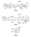
- FIG. 1is an illustration of a system for performing medical/surgical ablation with a plurality of cooling apparatus, according to an embodiment of the present disclosure, disposed on a coaxial cable thereof;
- FIG. 2Ais a perspective view of a hinged cooling apparatus according to an embodiment of the present disclosure
- FIG. 2Bis a transverse cross-sectional view of the hinged cooling apparatus of FIG. 2A ;
- FIG. 3Ais a perspective view of a slip-on cooling apparatus according to an embodiment of the present disclosure.
- FIG. 3Bis a transverse cross-sectional view of the slip-on cooling apparatus of FIG. 3A ;
- FIG. 4Ais plan view of cooling apparatus with an elongate body, according to another embodiment of the present disclosure, disposed on a coaxial cable of the surgical ablation system;
- FIG. 4Bis a plan view of the cooling apparatus of FIG. 4A ;
- FIG. 4Cis a plan view of the cooling apparatus of FIG. 4B with an elongate body configured to form a single wrap on a coaxial cable;
- FIG. 5is an illustration of a system for performing medical/surgical ablation including a plurality of cooling apparatus with fluid cooling, according to an embodiment of the present disclosure, disposed on a coaxial cable of the surgical ablation system;
- FIG. 6is a perspective view of the hinged cooling apparatus of FIG. 2A with fluid cooling
- FIG. 7is a perspective view of the slip-on cooling apparatus of FIG. 3A with fluid cooling
- FIG. 8Ais plan view of a multi-lumen cooling apparatus, according to an embodiment of the present disclosure, disposed on a coaxial cable of the surgical ablation system;
- FIG. 8Bis a plan view of the multi-lumen cooling apparatus of FIG. 8A ;
- FIG. 8Cis a transverse cross-sectional view of the multi-lumen cooling apparatus of FIG. 8B as taken through 8 C- 8 C of FIG. 8B ;
- FIG. 9is a perspective view of a system for performing medical/surgical ablation with a cooling sleeve apparatus, according to yet another embodiment of the present disclosure, disposed on the coaxial cable of the surgical ablation system;
- FIG. 10Ais a transverse cross-sectional view of one embodiment of the cooling sleeve apparatus of FIG. 9 with a cooling body filled with fluid and pressed against the coaxial cable;
- FIG. 10Bis a transverse cross-sectional view of the cooling sleeve apparatus of FIG. 9 with the cooling body empty;
- FIG. 10Cis a transverse cross-sectional view of another embodiment of the cooling sleeve apparatus in FIG. 9 with the cooling body filled with fluid and pressed against the coaxial cable;
- FIG. 10Dis a transverse cross-sectional view of the cooling sleeve apparatus of FIG. 9 with the cooling body empty.
- distalrefers to the portion that is furthest from the user and the term “proximal” refers to the portion that is closest to the user.
- proximalrefers to the portion that is closest to the user.
- terms such as “above”, “below”, “forward”, “rearward”, etc.refer to the orientation of the figures or the direction of components and are simply used for convenience of description.
- Microwave energyis typically delivered to an electrosurgical energy delivery apparatus, such as a microwave antenna assembly, through a coaxial cable.
- an electrosurgical energy delivery apparatussuch as a microwave antenna assembly
- FIG. 1a system for delivering microwave energy, including at least one coaxial cable cooling apparatus 100 according to an embodiment of the present disclosure, is shown as 10 .
- the microwave delivery system 10includes a microwave generator 15 , a coaxial cable 20 operatively connected or coupled to generator 15 , at least one coaxial cable cooling apparatus 100 disposed on coaxial cable 20 , and an electrosurgical energy delivery apparatus 30 including at least one microwave antenna 30 a capable of transmitting microwave energy.
- coaxial cable cooling apparatus 100includes a cooling body or housing 105 configured to attach to at least a portion of the coaxial cable 20 . At least a portion of the housing 105 is configured to absorb thermal energy from at least a portion of the coaxial cable 20 .
- Housing 105may include a cooling portion and a thermal dissipation or thermal energy removal portion.
- Cooling portionmay include a passive cooling means, such as, for example, thermal energy absorbing material with a high thermal mass or a thermal energy exchanging means, an active cooling means, such as, for example, fluid cooling, or any suitable combination thereof.
- Thermal dissipation or thermal energy removal portionmay provide a means of removing thermal energy from the coaxial cable 20 and/or cooling apparatus 100 .
- Various passive and active cooling means in accordance with the present disclosureare disclosed hereinbelow.
- microwave delivery system 10may include a plurality of cooling apparatuses 100 spaced from each other and disposed on the coaxial cable 20 . Positioning and spacing between the cooling apparatuses 100 on the coaxial cable 22 may be dependant on a number of factors. Factors include the thermal energy generated by the coaxial cable 20 , the thermal mass of the individual cooling apparatus 100 , the thermal energy absorption rate of the individual cooling apparatus 100 and one or more characteristics of the microwave energy, such as, for example, the frequency, phase and power of the microwave energy. The thermal energy generated by the coaxial cable 20 may depend upon the medical procedure including the length of time of the procedure, the energy delivered during the procedure, the type of tissue targeted by the procedure, and the type of device used for the procedure. The number of cooling apparatus 100 may depend on the spacing determined by the factors discussed above and the total length of the coaxial cable 20 . In one embodiment, only a single cooling apparatus 100 is utilized.
- the position of the hot spots on the coaxial cable 20may vary and may even move during a procedure thus making placement of the cooling apparatus 100 on an individual hot spot difficult.
- a plurality of cooling apparatus 100may be placed on coaxial cable 20 to provide uniform cooling of the coaxial cable 20 .
- spacing between hot spots on a coaxial cablemay be related to a characteristic of the wavelength, e.g., hot spots may be spaced every half wavelength along the length of the coaxial cable.
- cooling apparatus 100may be spaced uniformly along the coaxial cable 100 with the center of each cooling apparatus spaced one-half wavelength apart. While each individual cooling apparatus 100 may not be positioned directly on a hot spot, the distance from a cooling apparatus 100 to a hot spot, along the coaxial cable 20 , will be uniform.
- a coaxial cable 20includes an outer sheath 22 , an outer conductor 24 , an inner conductor 26 and a dielectric 28 between the outer conductor 24 and the inner conductor 26 .
- Efficient transmission of microwave energy, with minimal amount of microwave energy discharge or loss,requires the inner conductor 26 to be positioned at the approximate radial center of the outer conductor 24 .
- the dielectric 24both positions the inner conductor 26 at the approximate radial center of the outer conductor 24 and insulates the inner conductor 26 and outer conductor 24 by providing a uniform impedance between the inner and outer conductors 26 , 24 .
- a coaxial cable 20to efficiently transmit microwave energy, results in a coaxial cable 20 with excellent transmission properties and typically with very little thermal mass.
- particular amounts of energy discharged within the coaxial cablemay elevate the temperature of the coaxial cable to unacceptable levels. Cable heating is more prevalent with small, flexible cables that are needed when manual manipulation of the cable is required such as, for example, during the placement of a delivery apparatus 30 .
- a cooling apparatus 200in accordance with an embodiment of the present disclosure, is at least partially disposed on coaxial cable 20 .
- Cooling apparatus 200includes a cooling body or housing 205 configured to absorb thermal energy from at least a portion of the coaxial cable 20 .
- Housing 205includes an upper housing portion 205 a and a lower housing portion 205 b inter-connected by a hinge-member 207 (e.g., piano hinge, living hinge, etc.), or other suitable connector.
- Cooling apparatus 200may be reusable or disposable and may be either temporarily or permanently attached to the coaxial cable 20 .
- Cooling apparatus 200may include an attachment means to affix housing 205 to the coaxial cable 20 .
- attachment meansmay include at least one latch 210 extending from the upper housing portion 205 a that enters a corresponding slot 215 formed in the lower housing portion 205 b .
- Attachment meansmay lock the cooling apparatus 200 onto the coaxial cable 20 .
- a latch release 217is provided to slide in the direction of the arrow “A” to release latch 210 from slot 215 .
- Others suitable means of attaching the housing 205 onto the coaxial cablemay be used.
- the cooling apparatus 200includes a thermal mass that is greater than that of the coaxial cable 20 disposed therewithin. Attaching a cooling apparatus 200 such that cooling apparatus 200 is in thermal contact with the coaxial cable 20 increases the overall thermal mass of the body, i.e., the combined thermal mass of the coaxial cable 20 and the cooling apparatus 200 .
- upper housing portion 205 a and/or the lower housing portion 205 bmay draw thermal energy away from, and thereby cool, the coaxial cable 20 .
- increasing the thermal mass of the body, by attaching one or more cooling apparatus 200may decrease the rate at which the cable temperature increases.
- cooling apparatus 200while disposed on and absorbing thermal energy from coaxial cable 20 , may not alter and/or significantly change the physical properties of the coaxial cable 20 , e.g., the spacing and/or positioning of the inner conductor 26 , dielectric layer 28 or outer conductor 24 relative to each other. Additionally, cooling apparatus 200 may not alter and/or significantly change the electrical properties of the coaxial cable 20 , e.g., cable impedance and/or conductive properties thereof.
- an inner surface 205 b of the cooling apparatus 200is configured to contact the sheath 22 of the coaxial cable 20 when cooling apparatus 200 is operatively connected or coupled thereto.
- at least a portion of cooling apparatus 200may pierce the sheath 22 and make direct thermal contact with outer conductor 24 . Direct thermal contact between the cooling apparatus 200 and outer conductor 24 may be desirable to increase the rate of thermal energy removal from the coaxial cable 20 .
- a portion of the sheath 22may be removed to allow direct thermal contact between cooling apparatus 200 and outer conductor 24 .
- FIG. 2Bis a traverse cross-sectional view of the cooling apparatus 200 of FIG. 2A with the upper housing portion 205 a in an open position (shown in phantom) and in a closed position. In a closed position, the upper housing portion 205 a is adjacent the lower housing portion 205 b . As indicated by arrow “B”, the upper housing portion 205 a may pivot relative to the lower housing portion 205 b between a closed position and an open position.
- the coaxial cable 20is placed in the upper or lower housing portion 205 a , 205 b while cooling apparatus 200 is in an open position.
- the upper and lower housing portions 205 a , 205 bare then reposition to a closed position and latch 210 in upper housing portion 205 a connects with slot 215 in lower housing portion 205 b , thereby locking cooling apparatus 200 on coaxial cable 20 .
- Cooling apparatus 200may be removed from coaxial cable 20 by sliding latch release 217 in the direction of arrow “A” (see FIG. 2A ), disengaging latch 210 from slot 215 and repositioning the upper and lower housings 205 a , 205 b to an open position.
- Housing portions 205 a , 205 bmay each define respective cavities 225 for containing material 220 therein, the material 220 having a high thermal mass and/or high energy absorbing properties.
- housing 205may contain a meltable material 220 a , such as wax, disposed within the cavity 225 of housing portions 205 a , 205 b .
- the meltable material 220 amay be solid at room temperature or before cooling apparatus is disposed on the coaxial cable 20 .
- Meltable materialmay be any suitable material that exhibits a phase change while absorbing thermal energy. Phase change may be from a solid to a liquid, from a liquid to vapor or any other suitable phase change that results in the meltable material absorbing thermal energy.
- the melting point or temperature at which the phase change of the meltable material 220 a occursshould be below any unacceptable high temperature for the coaxial cable 20 .
- Various types of waxesmay be suitable because, depending on the specific wax used, the melting point may be between about 40° C. and about 100° C.
- Cavities 225 of housing portions 205 a , 205 bmay be fluid tight thereby sealing the meltable material 220 a therewithin.
- material 220may include a semi-solid or gel. Cooling may occur as the material evaporates from a semi-solid state to vapor or sublimates from solid to a gel.
- Meltable material 220 amay be, solid, soft, pliable or formable prior to the application of the cooling apparatus 100 to coaxial cable 20 to allow housing 205 to conform to coaxial cable 20 .
- the meltable material 220 amay be granulated, microcapsulated or powderized thus allowing an otherwise hard meltable material 220 a to generally conform to the coaxial cable 20 .
- granulating, microcapsulating or powderizing a meltable material 220 amay decrease the individual particle size and increases the overall surface area of the meltable material 220 a and may result in an increase in the rate of thermal energy absorption of material 220 a.
- material 220may include a meltable material 220 a and at least one thermally conductive material 220 b , such as, for example, aluminum or iron.
- the thermally conductive material 220 bmay be homogenously mixed with the meltable material 220 a such that thermally conductive material 220 b distributes the thermal energy throughout the cavities 225 and the meltable material 220 a absorbs the thermal energy.
- the homogenous mixture of a meltable material 220 a and a thermally conductive material 220 bmay result in material 220 with a high thermal mass and a high rate of thermal energy absorption. Addition of the thermally conductive material 220 b may evenly distribute the thermal energy throughout cavity 225 of housing portions 205 a , 205 b.
- thermally conductive materialmay not be homogenously mixed with the meltable material. Instead, thermally conductive material may be positioned within the cavities such that thermal energy is drawn away from the coaxial cable 20 , such as, for example, fins similar to that of a heat exchanger.
- the meltable material 220 amay be a wax selected from a group including insect wax, vegetable wax, mineral wax, animal wax, petroleum wax, synthetic wax and any suitable combination thereof.
- Usable insect waxesinclude but are not limited to beeswax, produced by honey bees, with a melting point between about 61° C.-66° C.; Chinese wax, produced by scale insects such as Coccus ceriferus and Brahmaea japomca (Coecoidea), with a melting point between about 82° C.-84° C.; wax produced by the Icerva purchasi and Dactylopius coccus , with a melting point of about 78° C. and between about 99° C.-101° C., respectively; and Shellac, a wax is secreted by the Lac insect, with a melting point between about 74° C.-78° C.
- Useful vegetable waxesinclude but are not limited to Bayberry wax, from the surface of the berries of the bayberry shrub, with a melting point of about 45° C.; Candelilla wax, from the Mexican shrubs Euphorbia cerifera and E. antisyphilitica , with a melting point between about 67° C.-79° C.; Carnauba wax, from the leaves of the Carnauba palm, with a melting point between about 78° C.-85° C.; Castor wax, formed from hydrogenated castor oil, with a melting point between about 61° C.-69° C.; Japan wax, formed from a byproduct of lacquer manufacture, with a melting point of about 53° C.; Ouricury wax, from the Brazilian Feather palm, with a melting point between about 81° C. and 84° C.; and Rice bran wax, obtained from rice bran, with a melting point between about 77° C.-86° C.
- Usable mineral waxesinclude but are not limited to Montan wax, extracted from lignite and brown coal, with a melting point between about 82° C.-95° C.; and Ozocerite, a naturally occurring wax found in lignite beds, with a melting point between about 58° C.-100° C.
- Usable animal waxesinclude but are not limited to Spermacet, obtained from the head cavities and blubber of the sperm whales and Lanolin, also known as wool wax, obtained from the sebaceous glands of sheep with a melting point between about 35° C.-42° C.
- Usable petroleum waxesinclude but are not limited to Paraffin wax, made of long-chain alkane hydrocarbons, with a melting point between about 47° C.-64° C.; and Microcrystalline wax, produced by de-oiling petrolatum, with a melting point between about 60° C.-80° C.
- Usable synthetic waxesincluding but are not limited to polyethylene waxes, based on polyethylene, and waxes chemically modified such as, for example, esterified or saponified, substituted amide waxes and polymerized a-olefins.
- Material 220may include any suitable material, or mixture of materials, capable of absorbing and retaining a thermal load.
- Cooling apparatus 300includes a cooling body or housing 305 forming a lumen 330 in the approximate radial center of the cooling housing 305 . Access to the lumen 330 is provided by a channel 335 extending through housing 305 and extending an entire length thereof. Housing 305 is sufficiently flexible such that housing 205 can be manipulated to open or expand channel 335 , in the direction of the opposing arrows “C”, to allow coaxial cable 20 to slip through channel 335 and into lumen 330 .
- a flap 340fastened to housing 305 on one side of channel 335 , may be used to close the channel 335 by selectively attaching to housing 305 at a flap attachment area 340 a on the second side of channel 335 .
- Flap attachment area 340 amay use any suitable attachment means, such as, for example, hook and loop type fasteners, adhesive, tape, snaps, buttons or latches.
- channel 335is opened by pulling the housing 305 in the direction of the opposing arrows “C” and the coaxial cable 20 is removed from lumen 330 .
- the diameter of lumen 330is sized to be substantially equal to an outer diameter of the coaxial cable 20 such that when the channel 335 is closed, with the coaxial cable 20 in the lumen 330 , the housing 305 makes substantial contact with a length of the coaxial cable 20 .
- housing 305forms a chamber 325 that contains thermal energy absorbing material 320 as discussed hereinabove. Material may be contained within chamber 325 by a fluid-tight manner.
- an internal surface of the housing 305 within the lumen 330may pierce the sheath 22 and make thermal contact with the outer conductor 24 to facilitate the removal of thermal energy from the coaxial cable 20 .
- Cooling apparatus 400includes an elongate cooling body 405 in the form of a tape-like structure for wrapping coaxial cable 20 . Cooling apparatus 400 may be wrapped along or around coaxial cable 20 , as illustrated in FIG. 4A . Cooling apparatus 400 includes a flap 440 on each end of cooling body 405 that attaches to a flap landing area 440 a and secures cooling apparatus 400 to the coaxial cable 20 . Housing 405 contains thermal energy absorbing material as discussed in the embodiments above.
- the length of coaxial cable 20 covered by the cooling apparatus 400is determined by the width of the cooling body 405 , the pitch or angle of the wrap, the amount of overlap between two adjacent wraps, the diameter of the coaxial cable 20 and the length of the cooling apparatus 400 .
- FIGS. 4A and 4Billustrate a cooling apparatus 400 wrapped approximately four times around a coaxial cable 20 , with little or no overlap between wraps, at a pitch of approximately 45 degrees.
- the length of coaxial cable 20 covered by the cooling apparatus 400may be approximately four times the width of the cooling body 405 .
- FIG. 4Billustrates an extended or unwrapped cooling apparatus 400 of FIG. 4A .
- the length and widthmay be larger or smaller based on the dimensions of coaxial cable covered by the cooling apparatus 400 .
- Increasing the length of cooling apparatus 400may increase the number of times the cooling apparatus 400 will wrap around the coaxial cable 20 .
- Increasing the width of cooling apparatus 400may increase the amount of coaxial cable 20 covered by each wrap.
- each flap 440 and the size and position of each flap attachment area 440 a on the cooling apparatus 400may be adjusted for different coaxial cable 20 dimensions.
- the center of the flap 440 and the center of the flap attachment area 440 aare spaced such that when the cooling apparatus 400 is wrapped around the coaxial cable 20 the flap 440 folds onto at least a portion of the flap attachment area 440 a .
- the spacing between the flap 440 and the flap attachment area 440 ais about equal to, or greater than, the circumference of the coaxial cable 20 . Spacing between the flap 440 and the flap attachment area 440 a may be adjusted for larger diameter or smaller diameter coaxial cables.
- a cooling apparatus 401is provided and includes a single-wrap around a portion of the coaxial cable. Cooling apparatus 401 may be applied to specific hot-spots in or along the transmission path, such as, for example, connections to the coaxial cable, connections between two coaxial cables and bends or kinks in a coaxial cable.
- the cooling apparatus 100 , 200 , 300 , 400 and 401 with passive cooling discussed hereinaboveare attached to a coaxial cable 20 thereby increasing the thermal mass of the body.
- the meltable materialcontained therewithin, absorbs energy and may change from a solid state to a melted state.
- meltable materialmay cool to a temperature below the melting point of the meltable material and may re-solidify to a solid state.
- a cooling apparatusmay absorbed an amount of thermal energy such that material in the cooling apparatus melts and coaxial cable and/or cooling apparatus may approach an unacceptable temperature.
- Clinicianmay replace the heated cooling apparatus, containing the melted material, with an unheated cooling apparatus, thereby providing additional passive cooling for the coaxial cable.
- cooling apparatuscools and meltable material re-solidifies to a solid-like state.
- cooling apparatus 400may contain a temperature sensor 470 to sense the temperature of the cooling apparatus 400 .
- Temperature sensor 470may include an indicator 470 a , such as, for example, a strip-type indicator or other suitable display, to provide the temperature of the cooling apparatus 400 to a clinician.
- sensormay include an electronic circuit (not explicitly shown) to measure and indicate a temperature.
- Electronic circuit(not explicitly shown) may include a means to communicate a temperature to a remote system, such as, for example, a computer or other suitable information collection system.
- a system for delivering microwave energyincluding at least one cooling apparatus 500 according to an embodiment of the present disclosure, for actively cooling a coaxial cable 20 is shown as 10 a .
- the microwave delivery system 10 aincludes a microwave generator 15 , a coaxial cable 20 with at least one coaxial cable cooling apparatus 500 disposed on the coaxial cable 20 , a system 40 for supplying cooling fluid and an electrosurgical energy delivery apparatus 30 , including at least one microwave antenna 30 a capable of transmitting microwave energy.
- Coaxial cable cooling apparatus 500(hereinafter “cooling apparatus 500 ”) includes a cooling body or housing 505 configured to attached to at least a portion of the coaxial cable 20 , at least one inlet member 545 , and at least one outlet member 547 .
- the one or more inlet members 545 and one or more outlet members 547may be disposed in, formed by, or defined by housing 505 .
- Cooling fluidis supplied to the at least one inlet member 545 by cooling fluid supply 40 and circulated through at least a portion of the housing 505 .
- the fluid circulated therethroughabsorbs thermal energy generated by the coaxial cable 20 from the cooling apparatus 500 , or any portion therewithin. Alternatively, the fluid circulating therethrough may absorb thermal energy directly from the coaxial cable 20 .
- Fluidis discharged from the housing 505 through the at least one outlet member 547 .
- FIG. 6illustrates a cooling apparatus 500 , similar to cooling apparatus 200 of FIG. 2A , with a plurality of inlets 545 a - 545 d disposed in the lower housing 505 b .
- Fluidis delivered to at least one of the inlets 545 a - 545 d and circulated through the lower housing 505 b .
- a jumper hose 549fluidly inter-connects to upper housing 505 a and lower housing 505 b to circulate fluid between the upper housing 505 a and the lower housing 505 b .
- Fluidis discharged from the cooling apparatus 500 through at least one of the plurality of the outlets 547 a - 547 b disposed in the upper housing 505 a .
- Fluid circulated through housing 505may absorb thermal energy from at least one of the lower housing 505 a , the upper housings 505 b and the material contained therewithin.
- Materialmay include a material with a high thermal mass and high energy absorbing properties as discussed herein.
- cooling fluid supply 40may include a pump 41 for circulating the fluid, a cooling unit 42 for cooling the fluid returned from the cooling apparatus 500 through the return manifold 43 .
- Fluidmay be a thermally conductive fluid, such as, for example, water, saline, ammonium chloride, sodium nitrate, potassium chloride or any suitable fluid selected for the intended purpose of dissipating heat.
- FIG. 7illustrates yet another embodiment of a cooling apparatus 700 of the present disclosure.
- Cooling apparatus 700includes a cooling body or housing 705 , defining an inner lumen 730 and a channel 735 , and an inlet 745 and an outlet 747 formed in the housing 705 .
- Flap 740connects to the housing 705 on one side of the channel 735 and attaches to flap attachment area 740 a on housing 705 on the opposite side of channel 735 .
- Cooling fluidis supplied to inlet 745 of housing 705 , circulated through housing 705 before being discharged through outlet 747 . Cooling fluid may be circulated through a portion of the housing 705 adjacent to and in thermal communication with the coaxial cable 20 to absorb thermal energy therefrom.
- Cooling apparatus 800includes a cooling body, or housing 805 , having at least two tubes 850 a , 850 b , one or more attachment flaps 840 , and defining one or more flap attachment areas 840 a .
- An inlet member 845 and an outlet member 847may be fluidly connected to, or are integrally formed with, cooling tube 850 a and return tube 850 b , respectively. Fluid is supplied to inlet member 845 and is circulated though cooling tube 850 a and return tube 850 b . Thermal energy from the coaxial cable 20 and/or the cooling apparatus 800 is absorbed by the cooling fluid and is discharged through return tube 850 b.
- cooling apparatus 800is disposed on a coaxial cable 20 . Cooling apparatus 800 is wrapped around the coaxial cable 20 . Cooling apparatus 800 is secured on each end by flaps 840 that selectively attach to flap attachment areas 840 a.
- the absorption rate of thermal energy from the coaxial cable 20 by cooling apparatus 800is dependant on several factors.
- One factoris the contact surface area between the cooling and return tubes 850 a , 850 b and coaxial cable 20 .
- the contact surface area between the cooling and return tubes 850 a , 850 bmay be increased by forming cooling and return tubes 850 a , 850 b from flexible and/or malleable material such that when disposed on coaxial cable 20 the cooling and return tubes 850 a , 850 b conform to the surface of the coaxial cable 20 .
- Cooling and return tubes 850 a , 850 bmay be formed from any suitable tubing such as, for example, medical tubing and paratubes.
- cooling tube 850 amay be formed from a suitable material that conforms to the coaxial cable 20 and the return tube 850 b , which carries fluid already heated in the cooling tube 850 a , may be formed from a suitable material that does not conform to the coaxial cable.
- the cooling tube 850 acontacts the coaxial cable 20 and the return tube 850 b is spaced away from the coaxial cable 20 , thereby not making contact with the coaxial cable 20 .
- the at least one or more tubes 850 a , 850 bmay be formed from multi-lumen tubing made from various materials such as, for example, polytetrafluoroethylene (PTFE), such as the material sold under the trademark TeflonTM and available from DuPont, perfluoroalkoxy (PFA), polytetrafluoroethylene (FEP) or expanded PTFE (ePTFE).
- PTFEpolytetrafluoroethylene
- TeflonTMperfluoroalkoxy
- FEPpolytetrafluoroethylene
- ePTFEexpanded PTFE
- FIG. 8Cis a transverse cross-sectional view of the cooling apparatus 800 of FIG. 8B formed from a multi-lumen tube 850 .
- Multi-lumen tube 850forms a cooling tube 850 a and a return tube 850 b with at least one common wall shared therebetween.
- a system for delivering microwave energyincluding at least one coaxial cable cooling sleeve apparatus 900 , according to an embodiment of the present disclosure, for actively cooling a coaxial cable 20 is shown as 10 b .
- the microwave delivery system 12includes a microwave generator 15 , a coaxial cable 20 with at least one coaxial cable cooling sleeve apparatus 900 disposed on the coaxial cable 20 , a system 40 for supplying cooling fluid and an electrosurgical energy delivery apparatus 30 , including at least one microwave antenna 30 a , capable of transmitting microwave energy.
- Coaxial cable cooling sleeve apparatus 900(hereinafter “cooling sleeve apparatus”) includes a cooling body 905 , configure to surround at least a portion of coaxial cable 20 , at least one inlet 945 , and at least one outlet 947 .
- Cooling fluidis supplied to the at least one inlet 945 by cooling fluid supply 40 via a conduit 40 a and circulated through at least a portion of the cooling body 905 .
- Fluid circulated through cooling body 905absorbs thermal energy generated by the coaxial cable 20 and/or from the cooling apparatus 900 , and/or any portion therewithin.
- the heated fluidis discharged through the outlet 947 via conduit 40 b.
- FIGS. 10A-10B and FIGS. 10C-10Dtransverse cross-section views of two embodiments of the cooling sleeve apparatus 900 of FIG. 9 are illustrated.
- the housing 905 of a cooling sleeve apparatus 901forms inner and outer concentric portions 951 a , 951 b , respectively, each forming at least one fluid tight chamber therewithin.
- the housing 905 of a cooling sleeve apparatus 902forms a cooling portion 951 c and a return portion 951 d , each defining a fluid-tight chamber therewithin.
- FIGS. 10A-10B and FIGS. 10C-10Dtransverse cross-section views of two embodiments of the cooling sleeve apparatus 900 of FIG. 9 are illustrated.
- the housing 905 of a cooling sleeve apparatus 901forms inner and outer concentric portions 951 a , 951 b , respectively, each forming at least one fluid tight chamber therewithin.
- the fluid-tight chambersare filled with fluid thereby pressing the inner surface 905 b of the housing 905 into the coaxial cable 20 .
- Inner surface 905 bmay be flexible and/or stretchable such that inner surface 905 b of the housing 905 and the outer surface 905 a of the coaxial cable 20 form suitable thermally conductive contact with one another.
- the inlet 945connects to the inner concentric portion 951 a of the cooling apparatus 901 in FIGS. 10A and 10B , or to the cooling portion 951 c of the cooling apparatus 902 in FIGS. 10C and 10D , and supplies cooling fluid thereto.
- the outlet 947connects to the outer concentric portion 951 b of the cooling apparatus 901 in FIGS. 10A and 10B , or to the return portion 951 d of the cooling apparatus 902 in FIGS. 10C and 10D .
- fluidpasses from the inner concentric portion 951 a to the outer concentric portion 951 b , or from the cooling portion 951 c to the return portion 951 d , through openings therebetween (not explicitly shown). Fluid then flows proximally through the outer concentric portion 951 b or the return portion 951 d and is discharged through the outlet 947 .
- the fluid-tight chambersare not fluid-filled thereby defining a space or cavity 960 between the inner surface 905 b of the housing 905 and the coaxial cable 20 .
- the shape of the cooling sleeve apparatus 901 , 902may be defined by a rigid or semi-rigid outer surface 905 a of housing 905 . The shape may be maintained by the outer surface 905 a after a majority of the fluid is removed. Removal of fluid from the housing 905 may create a vacuum therewithin and may pull the inner surface 905 b of the housing 905 toward the outer surface 905 a thereby increasing the size or volume of space or cavity 960 between the inner surface 905 b of the housing 905 and the coaxial cable 20 .
- Space 960may be sufficiently large to allow the coaxial cable 20 to be threaded or inserted through space 960 thus providing a means of attaching the cooling apparatus 901 , 902 to the coaxial cable 20 .
- the present applicationdiscloses apparatus and methods for cooling coaxial cables. It is envisioned that the various embodiments described hereinabove may be combined. For example, elements of the passive cooling apparatus may be applied to the various active cooling apparatus. While the embodiments contained herewithin are described in the context of cooling coaxial cables transmitting microwave energy any apparatus or method may be used to cool any cable, wire or elongated member. Modification of the above-described apparatuses and methods, and variations of aspects of the disclosure that are obvious to those of skill in the art are intended to be within the scope of the claims.
Landscapes
- Engineering & Computer Science (AREA)
- Physics & Mathematics (AREA)
- Chemical & Material Sciences (AREA)
- Thermal Sciences (AREA)
- Mechanical Engineering (AREA)
- General Engineering & Computer Science (AREA)
- Chemical Kinetics & Catalysis (AREA)
- Combustion & Propulsion (AREA)
- Materials Engineering (AREA)
- Organic Chemistry (AREA)
- Surgical Instruments (AREA)
Abstract
Description
Claims (10)
Priority Applications (1)
| Application Number | Priority Date | Filing Date | Title |
|---|---|---|---|
| US12/814,787US8093500B2 (en) | 2007-06-18 | 2010-06-14 | Microwave cable cooling |
Applications Claiming Priority (2)
| Application Number | Priority Date | Filing Date | Title |
|---|---|---|---|
| US11/820,193US7777130B2 (en) | 2007-06-18 | 2007-06-18 | Microwave cable cooling |
| US12/814,787US8093500B2 (en) | 2007-06-18 | 2010-06-14 | Microwave cable cooling |
Related Parent Applications (1)
| Application Number | Title | Priority Date | Filing Date |
|---|---|---|---|
| US11/820,193DivisionUS7777130B2 (en) | 2007-06-18 | 2007-06-18 | Microwave cable cooling |
Publications (2)
| Publication Number | Publication Date |
|---|---|
| US20100243287A1 US20100243287A1 (en) | 2010-09-30 |
| US8093500B2true US8093500B2 (en) | 2012-01-10 |
Family
ID=40131241
Family Applications (2)
| Application Number | Title | Priority Date | Filing Date |
|---|---|---|---|
| US11/820,193Expired - Fee RelatedUS7777130B2 (en) | 2007-06-18 | 2007-06-18 | Microwave cable cooling |
| US12/814,787Expired - Fee RelatedUS8093500B2 (en) | 2007-06-18 | 2010-06-14 | Microwave cable cooling |
Family Applications Before (1)
| Application Number | Title | Priority Date | Filing Date |
|---|---|---|---|
| US11/820,193Expired - Fee RelatedUS7777130B2 (en) | 2007-06-18 | 2007-06-18 | Microwave cable cooling |
Country Status (1)
| Country | Link |
|---|---|
| US (2) | US7777130B2 (en) |
Cited By (12)
| Publication number | Priority date | Publication date | Assignee | Title |
|---|---|---|---|---|
| US20110295246A1 (en)* | 2010-05-26 | 2011-12-01 | Vivant Medical, Inc. | System and Method for Chemically Cooling an Ablation Antenna |
| WO2016210001A1 (en)* | 2015-06-22 | 2016-12-29 | Pyrexar Medical Inc. | Hyperthermia electromagnetic energy applicator housing and hyperthermia patient support system |
| US9566115B2 (en) | 2009-07-28 | 2017-02-14 | Neuwave Medical, Inc. | Energy delivery systems and uses thereof |
| US9861440B2 (en) | 2010-05-03 | 2018-01-09 | Neuwave Medical, Inc. | Energy delivery systems and uses thereof |
| US10363092B2 (en) | 2006-03-24 | 2019-07-30 | Neuwave Medical, Inc. | Transmission line with heat transfer ability |
| US10376314B2 (en) | 2006-07-14 | 2019-08-13 | Neuwave Medical, Inc. | Energy delivery systems and uses thereof |
| US10531917B2 (en) | 2016-04-15 | 2020-01-14 | Neuwave Medical, Inc. | Systems and methods for energy delivery |
| US10667860B2 (en) | 2011-12-21 | 2020-06-02 | Neuwave Medical, Inc. | Energy delivery systems and uses thereof |
| US10952792B2 (en) | 2015-10-26 | 2021-03-23 | Neuwave Medical, Inc. | Energy delivery systems and uses thereof |
| US11389235B2 (en) | 2006-07-14 | 2022-07-19 | Neuwave Medical, Inc. | Energy delivery systems and uses thereof |
| US11672596B2 (en) | 2018-02-26 | 2023-06-13 | Neuwave Medical, Inc. | Energy delivery devices with flexible and adjustable tips |
| US11832879B2 (en) | 2019-03-08 | 2023-12-05 | Neuwave Medical, Inc. | Systems and methods for energy delivery |
Families Citing this family (24)
| Publication number | Priority date | Publication date | Assignee | Title |
|---|---|---|---|---|
| US7777130B2 (en)* | 2007-06-18 | 2010-08-17 | Vivant Medical, Inc. | Microwave cable cooling |
| US8181995B2 (en)* | 2007-09-07 | 2012-05-22 | Tyco Healthcare Group Lp | Cool tip junction |
| US8945111B2 (en) | 2008-01-23 | 2015-02-03 | Covidien Lp | Choked dielectric loaded tip dipole microwave antenna |
| US9949794B2 (en) | 2008-03-27 | 2018-04-24 | Covidien Lp | Microwave ablation devices including expandable antennas and methods of use |
| US8845627B2 (en) | 2008-08-22 | 2014-09-30 | Boston Scientific Scimed, Inc. | Regulating pressure to lower temperature in a cryotherapy balloon catheter |
| US20100045559A1 (en)* | 2008-08-25 | 2010-02-25 | Vivant Medical, Inc. | Dual-Band Dipole Microwave Ablation Antenna |
| US9173706B2 (en)* | 2008-08-25 | 2015-11-03 | Covidien Lp | Dual-band dipole microwave ablation antenna |
| US8251987B2 (en) | 2008-08-28 | 2012-08-28 | Vivant Medical, Inc. | Microwave antenna |
| US8118808B2 (en)* | 2009-03-10 | 2012-02-21 | Vivant Medical, Inc. | Cooled dielectrically buffered microwave dipole antenna |
| US8343145B2 (en)* | 2009-09-28 | 2013-01-01 | Vivant Medical, Inc. | Microwave surface ablation using conical probe |
| US9770294B2 (en) | 2011-01-05 | 2017-09-26 | Covidien Lp | Energy-delivery devices with flexible fluid-cooled shaft, inflow/outflow junctions suitable for use with same, and systems including same |
| US9011421B2 (en) | 2011-01-05 | 2015-04-21 | Covidien Lp | Energy-delivery devices with flexible fluid-cooled shaft, inflow/outflow junctions suitable for use with same, and systems including same |
| US9017319B2 (en) | 2011-01-05 | 2015-04-28 | Covidien Lp | Energy-delivery devices with flexible fluid-cooled shaft, inflow/outflow junctions suitable for use with same, and systems including same |
| US8932281B2 (en) | 2011-01-05 | 2015-01-13 | Covidien Lp | Energy-delivery devices with flexible fluid-cooled shaft, inflow/outflow junctions suitable for use with same, and systems including same |
| US9119648B2 (en) | 2012-01-06 | 2015-09-01 | Covidien Lp | System and method for treating tissue using an expandable antenna |
| US9113931B2 (en) | 2012-01-06 | 2015-08-25 | Covidien Lp | System and method for treating tissue using an expandable antenna |
| CN108139015B (en)* | 2015-08-20 | 2020-05-12 | 哈金森公司 | Assembly with intermediate positioning portion for thermal insulation and hinged panel |
| WO2017197114A1 (en) | 2016-05-11 | 2017-11-16 | Affera, Inc. | Anatomical model generation |
| WO2017197294A1 (en) | 2016-05-12 | 2017-11-16 | Affera, Inc. | Three-dimensional cardiac representation |
| DE102016109550A1 (en)* | 2016-05-24 | 2017-11-30 | Yazaki Systems Technologies Gmbh | Wiring harness and arrangement with such a wiring harness |
| DE102018120932B4 (en)* | 2018-08-28 | 2021-02-18 | Volkswagen Aktiengesellschaft | Cable section, system and method for power transmission within a motor vehicle and a motor vehicle, having a cable section |
| US12268456B2 (en) | 2019-01-23 | 2025-04-08 | Affera, Inc. | Systems and methods for therapy annotation |
| WO2021026470A1 (en)* | 2019-08-07 | 2021-02-11 | Biocompatibles Uk Limited | Cooling system for surgical device |
| CN112710935B (en)* | 2021-03-29 | 2021-06-25 | 吉安诺惠诚莘科技有限公司 | Power wire and cable protective layer ablation condition pre-alarming system and method |
Citations (159)
| Publication number | Priority date | Publication date | Assignee | Title |
|---|---|---|---|---|
| DE390937C (en) | 1922-10-13 | 1924-03-03 | Adolf Erb | Device for internal heating of furnace furnaces for hardening, tempering, annealing, quenching and melting |
| US2029420A (en) | 1929-05-23 | 1936-02-04 | American Telephone & Telegraph | Concentric conductor transmission system |
| US2165961A (en) | 1935-10-22 | 1939-07-11 | Emi Ltd | High frequency signaling system |
| US2510358A (en) | 1946-03-20 | 1950-06-06 | Rca Corp | Art of making concentric transmission lines |
| DE1099658B (en) | 1959-04-29 | 1961-02-16 | Siemens Reiniger Werke Ag | Automatic switch-on device for high-frequency surgical devices |
| FR1275415A (en) | 1960-09-26 | 1961-11-10 | Device for detecting disturbances for electrical installations, in particular electrosurgery | |
| US3060210A (en)* | 1960-05-12 | 1962-10-23 | Petrolite Corp | Polyaminomethyl phenols |
| DE1139927B (en) | 1961-01-03 | 1962-11-22 | Friedrich Laber | High-frequency surgical device |
| DE1149832B (en) | 1961-02-25 | 1963-06-06 | Siemens Reiniger Werke Ag | High frequency surgical apparatus |
| FR1347865A (en) | 1962-11-22 | 1964-01-04 | Improvements to diathermo-coagulation devices | |
| DE1439302A1 (en) | 1963-10-26 | 1969-01-23 | Siemens Ag | High-frequency surgical device |
| US3634606A (en) | 1970-06-15 | 1972-01-11 | Northern Electric Co | Outer conductor for coaxial cable |
| SU401367A1 (en) | 1971-10-05 | 1973-10-12 | Тернопольский государственный медицинский институт | BIAKTIVNYE ELECTRO SURGICAL INSTRUMENT |
| US3777371A (en) | 1972-02-16 | 1973-12-11 | Northern Electric Co | Method of controlling the characteristics impedance of coaxial cables |
| DE2439587A1 (en) | 1973-08-23 | 1975-02-27 | Matburn Holdings Ltd | ELECTROSURGICAL DEVICE |
| US3885083A (en) | 1969-09-29 | 1975-05-20 | Gen Cable Corp | Pressure fused watertight disc coaxial cable |
| DE2455174A1 (en) | 1973-11-21 | 1975-05-22 | Termiflex Corp | INPUT / OUTPUT DEVICE FOR DATA EXCHANGE WITH DATA PROCESSING DEVICES |
| US3893355A (en) | 1973-12-21 | 1975-07-08 | Giddings & Lewis | Coolant supply system for cutting tools in a machine tool |
| DE2407559A1 (en) | 1974-02-16 | 1975-08-28 | Dornier System Gmbh | Tissue heat treatment probe - has water cooling system which ensures heat development only in treated tissues |
| DE2415263A1 (en) | 1974-03-29 | 1975-10-02 | Aesculap Werke Ag | Surgical H.F. coagulation probe has electrode tongs - with exposed ends of insulated conductors forming tong-jaws |
| DE2429021A1 (en) | 1974-06-18 | 1976-01-08 | Erbe Elektromedizin | Remote control for HF surgical instruments - uses cable with two conductors at most |
| US3943470A (en) | 1973-08-06 | 1976-03-09 | Sealectro Corporation | Right angle connector |
| FR2235669B1 (en) | 1973-07-07 | 1976-05-07 | Lunacek Boris | |
| DE2460481A1 (en) | 1974-12-20 | 1976-06-24 | Delma Elektro Med App | Electrode grip for remote HF surgical instrument switching - has shaped insulated piece with contact ring of sterilizable (silicon) rubber |
| DE2627679A1 (en) | 1975-06-26 | 1977-01-13 | Marcel Lamidey | HEMATISTIC HIGH FREQUENCY EXTRACTOR FORCEPS |
| FR2276027B3 (en) | 1974-06-25 | 1977-05-06 | Medical Plastics Inc | |
| US4092485A (en) | 1975-11-03 | 1978-05-30 | Gould, Inc. | Gas insulated electrical high or very high voltage cable |
| US4143649A (en) | 1977-01-24 | 1979-03-13 | George Foti | Pump for closed circulation system |
| DE2823291A1 (en) | 1978-05-27 | 1979-11-29 | Rainer Ing Grad Koch | Coagulation instrument automatic HF switching circuit - has first lead to potentiometer and second to transistor base |
| SU727201A2 (en) | 1977-11-02 | 1980-04-15 | Киевский Научно-Исследовательский Институт Нейрохирургии | Electric surgical apparatus |
| US4198828A (en) | 1977-06-09 | 1980-04-22 | Societe d'Etudes d'Automatisation, de Regulation et d'Appareils de Mesures S.A. | Cryostat and coolant-supply system therefore |
| FR2313708B1 (en) | 1975-06-02 | 1980-07-04 | Sybron Corp | |
| DE2504280C3 (en) | 1975-02-01 | 1980-08-28 | Hans Heinrich Prof. Dr. 8035 Gauting Meinke | Device for cutting and / or coagulating human tissue with high frequency current |
| DE2803275C3 (en) | 1978-01-26 | 1980-09-25 | Aesculap-Werke Ag Vormals Jetter & Scheerer, 7200 Tuttlingen | Remote switching device for switching a monopolar HF surgical device |
| USD263020S (en) | 1980-01-22 | 1982-02-16 | Rau Iii David M | Retractable knife |
| DE3045996A1 (en) | 1980-12-05 | 1982-07-08 | Medic Eschmann Handelsgesellschaft für medizinische Instrumente mbH, 2000 Hamburg | Electro-surgical scalpel instrument - has power supply remotely controlled by surgeon |
| DE2540968C2 (en) | 1975-09-13 | 1982-12-30 | Erbe Elektromedizin GmbH, 7400 Tübingen | Device for switching on the coagulation current of a bipolar coagulation forceps |
| DE2602517C3 (en) | 1975-01-23 | 1983-01-13 | Dentsply International Inc., 17404 York, Pa. | Device for monitoring the current return conductor in an electrosurgical HF device |
| US4377547A (en) | 1982-01-18 | 1983-03-22 | Minnesota Mining And Manufacturing Company | Molded high voltage splice body |
| FR2517953A1 (en) | 1981-12-10 | 1983-06-17 | Alvar Electronic | Diaphanometer for optical examination of breast tissue structure - measures tissue transparency using two plates and optical fibre bundle cooperating with photoelectric cells |
| US4415763A (en) | 1980-11-14 | 1983-11-15 | Westinghouse Electric Corp. | Gas-insulated transmission line having improved outer enclosure |
| US4493710A (en) | 1983-11-14 | 1985-01-15 | Ivy Medical, Inc. | Intravenous drip rate control device |
| DE3143421C2 (en) | 1980-11-04 | 1985-05-02 | The Agency Of Industrial Science And Technology, Tokio/Tokyo | Laser scalpel |
| FR2502935B1 (en) | 1981-03-31 | 1985-10-04 | Dolley Roger | METHOD AND DEVICE FOR CONTROLLING THE COAGULATION OF TISSUES USING A HIGH FREQUENCY CURRENT |
| US4648919A (en)* | 1984-09-18 | 1987-03-10 | Raychem Corp. | Protection of cable splice |
| FR2573301B3 (en) | 1984-11-16 | 1987-04-30 | Lamidey Gilles | SURGICAL PLIERS AND ITS CONTROL AND CONTROL APPARATUS |
| DE2946728C2 (en) | 1979-11-20 | 1987-07-30 | Erbe Elektromedizin Gmbh, 7400 Tuebingen, De | |
| DE3120102C2 (en) | 1981-05-20 | 1987-08-20 | Fischer Met Gmbh, 7800 Freiburg, De | |
| EP0246350A1 (en) | 1986-05-23 | 1987-11-25 | Erbe Elektromedizin GmbH. | Coagulation electrode |
| DE8712328U1 (en) | 1987-09-11 | 1988-02-18 | Jakoubek, Franz, 7201 Emmingen-Liptingen | Endoscopy forceps |
| USD295894S (en) | 1985-09-26 | 1988-05-24 | Acme United Corporation | Disposable surgical scissors |
| USD295893S (en) | 1985-09-25 | 1988-05-24 | Acme United Corporation | Disposable surgical clamp |
| DE3711511C1 (en) | 1987-04-04 | 1988-06-30 | Hartmann & Braun Ag | Method for determining gas concentrations in a gas mixture and sensor for measuring thermal conductivity |
| DE3510586C2 (en) | 1985-03-23 | 1988-07-28 | Erbe Elektromedizin Gmbh, 7400 Tuebingen, De | |
| US4865123A (en) | 1987-10-22 | 1989-09-12 | Fujitsu Limited | Apparatus for supplying cooling fluid |
| DE2820908C2 (en) | 1977-05-16 | 1989-11-16 | Joseph Coubron Fr Skovajsa | |
| US4977547A (en)* | 1985-06-07 | 1990-12-11 | Hoechst Celanese Corp. | Method of detecting sound in water using piezoelectric-polymer composites with 0-3 connectivity |
| US5048598A (en) | 1989-02-06 | 1991-09-17 | Fujitsu Limited | Reservior tank for a liquid cooling system |
| US5147161A (en) | 1991-10-28 | 1992-09-15 | Whiting Robert L | Retrofit coolant supply system for a machine tool |
| US5190421A (en) | 1991-11-20 | 1993-03-02 | Hardinge Brothers, Inc. | Coolant supply system for a machine tool |
| DE4238263A1 (en) | 1991-11-15 | 1993-05-19 | Minnesota Mining & Mfg | Adhesive comprising hydrogel and crosslinked polyvinyl:lactam - is used in electrodes for biomedical application providing low impedance and good mechanical properties when water and/or moisture is absorbed from skin |
| EP0521264A3 (en) | 1991-07-03 | 1993-06-16 | W.L. Gore & Associates Gmbh | Antenna device with feed |
| EP0556705A1 (en) | 1992-02-20 | 1993-08-25 | DELMA ELEKTRO-UND MEDIZINISCHE APPARATEBAU GESELLSCHAFT mbH | High frequency surgery device |
| EP0558429A1 (en) | 1992-02-26 | 1993-09-01 | PECHINEY RECHERCHE (Groupement d'Intérêt Economique géré par l'ordonnance no. 67-821 du 23 Septembre 1967) | Method of simultaneous measuring of electrical resistivety and thermal conductivity |
| US5312658A (en)* | 1991-05-07 | 1994-05-17 | Progressive Polymerics Inc. | Conduits having a shock absorbing shell and method for their formation |
| US5334193A (en) | 1992-11-13 | 1994-08-02 | American Cardiac Ablation Co., Inc. | Fluid cooled ablation catheter |
| US5348554A (en) | 1992-12-01 | 1994-09-20 | Cardiac Pathways Corporation | Catheter for RF ablation with cooled electrode |
| US5358515A (en) | 1989-08-16 | 1994-10-25 | Deutsches Krebsforschungzentrum Stiftung Des Offentlichen Rechts | Microwave hyperthermia applicator |
| DE4303882C2 (en) | 1993-02-10 | 1995-02-09 | Kernforschungsz Karlsruhe | Combination instrument for separation and coagulation for minimally invasive surgery |
| DE3604823C2 (en) | 1986-02-15 | 1995-06-01 | Lindenmeier Heinz | High frequency generator with automatic power control for high frequency surgery |
| CN1103807A (en) | 1993-11-17 | 1995-06-21 | 刘中一 | Multi-frequency micro-wave therapeutic instrument |
| US5535818A (en) | 1992-10-12 | 1996-07-16 | Fujitsu Limited | Cooling system for electronic device |
| DE29616210U1 (en) | 1996-09-18 | 1996-11-14 | Olympus Winter & Ibe Gmbh, 22045 Hamburg | Handle for surgical instruments |
| US5620440A (en) | 1993-11-13 | 1997-04-15 | Richard Wolf Gmbh | Medical instrument for applying hot gas |
| DE19608716C1 (en) | 1996-03-06 | 1997-04-17 | Aesculap Ag | Bipolar surgical holding instrument |
| DE3904558C2 (en) | 1989-02-15 | 1997-09-18 | Lindenmeier Heinz | Automatically power-controlled high-frequency generator for high-frequency surgery |
| US5703536A (en) | 1996-04-08 | 1997-12-30 | Harris Corporation | Liquid cooling system for high power solid state AM transmitter |
| DE19751106A1 (en) | 1996-11-27 | 1998-05-28 | Eastman Kodak Co | Laser printer with array of laser diodes |
| DE19717411A1 (en) | 1997-04-25 | 1998-11-05 | Aesculap Ag & Co Kg | Monitoring of thermal loading of patient tissue in contact region of neutral electrode of HF treatment unit |
| DE3942998C2 (en) | 1989-12-27 | 1998-11-26 | Delma Elektro Med App | High frequency electrosurgical unit |
| US5843021A (en) | 1994-05-09 | 1998-12-01 | Somnus Medical Technologies, Inc. | Cell necrosis apparatus |
| DE19751108A1 (en) | 1997-11-18 | 1999-05-20 | Beger Frank Michael Dipl Desig | Electrosurgical operation tool, especially for diathermy |
| DE19801173C1 (en) | 1998-01-15 | 1999-07-15 | Kendall Med Erzeugnisse Gmbh | Clamp connector for film electrodes |
| US5951546A (en) | 1994-12-13 | 1999-09-14 | Lorentzen; Torben | Electrosurgical instrument for tissue ablation, an apparatus, and a method for providing a lesion in damaged and diseased tissue from a mammal |
| US5951216A (en) | 1997-09-19 | 1999-09-14 | Antoun; Gregory S. | Programmable, variable volume and pressure, coolant system |
| EP0836868A3 (en) | 1996-10-18 | 1999-11-24 | Gebr. Berchtold GmbH & Co. | High frequency surgical apparatus and method for operating same |
| US6007571A (en) | 1996-04-25 | 1999-12-28 | Urologix, Inc. | Liquid coolant supply system |
| USD424694S (en) | 1998-10-23 | 2000-05-09 | Sherwood Services Ag | Forceps |
| USD425201S (en) | 1998-10-23 | 2000-05-16 | Sherwood Services Ag | Disposable electrode assembly |
| DE19848540A1 (en) | 1998-10-21 | 2000-05-25 | Reinhard Kalfhaus | Circuit layout and method for operating a single- or multiphase current inverter connects an AC voltage output to a primary winding and current and a working resistance to a transformer's secondary winding and current. |
| US6106504A (en) | 1998-07-15 | 2000-08-22 | Urrutia; Hector | Drip chamber for medical fluid delivery system |
| US6112813A (en)* | 1997-02-20 | 2000-09-05 | Head; Philip | Method of providing a conduit and continuous coiled tubing system |
| US6134476A (en) | 1996-04-17 | 2000-10-17 | The United States Of America As Represented By The Administrator Of The National Aeronautics And Space Administration | Transcatheter antenna for microwave treatment |
| US6149677A (en) | 1998-03-31 | 2000-11-21 | Innercool Therapies, Inc. | Circulating fluid hypothermia method |
| JP2000342599A (en) | 1999-05-21 | 2000-12-12 | Gyrus Medical Ltd | Generator for electrosurgical operation, electrosurgical operation system, method for operating this system and method for performing amputation and resection of tissue by electrosurgical operation |
| JP2000350732A (en) | 1999-05-21 | 2000-12-19 | Gyrus Medical Ltd | Electrosurgical system, generator for electrosurgery, and method for cutting or excising tissue by electrosurgery |
| JP2001008944A (en) | 1999-05-28 | 2001-01-16 | Gyrus Medical Ltd | Electric surgical signal generator and electric surgical system |
| JP2001029356A (en) | 1999-06-11 | 2001-02-06 | Gyrus Medical Ltd | Electric and surgical signal generator |
| JP2001128990A (en) | 1999-05-28 | 2001-05-15 | Gyrus Medical Ltd | Electro surgical instrument and electrosurgical tool converter |
| DE4339049C2 (en) | 1993-11-16 | 2001-06-28 | Erbe Elektromedizin | Surgical system configuration facility |
| US6259067B1 (en) | 1998-10-16 | 2001-07-10 | Medical Solutions, Inc. | Temperature control system and method for heating and maintaining medical items at desired temperatures |
| US6259074B1 (en) | 1999-10-26 | 2001-07-10 | Sims Level 1, Inc. | Apparatus for regulating the temperature of a fluid |
| JP2001231870A (en) | 2000-02-23 | 2001-08-28 | Olympus Optical Co Ltd | Moisturizing treatment apparatus |
| USD449886S1 (en) | 1998-10-23 | 2001-10-30 | Sherwood Services Ag | Forceps with disposable electrode |
| US6348049B1 (en) | 1994-03-30 | 2002-02-19 | Denco, Inc. | Surgical/medical tubing and containers for use in conveying medical solutions and the like |
| US6355024B1 (en) | 1999-07-14 | 2002-03-12 | Mallinckrodt Inc. | Medical fluid delivery system |
| US6371157B1 (en) | 2000-09-29 | 2002-04-16 | Thales Broadcast & Multimedia, Inc. | Method, system and computer program product for self-draining plumbing for liquid-cooled devices |
| US6383180B1 (en) | 1999-01-25 | 2002-05-07 | Cryocath Technologies Inc. | Closed loop catheter coolant system |
| USRE37704E1 (en) | 1990-03-22 | 2002-05-14 | Argomed Ltd. | Thermal treatment apparatus |
| USD457958S1 (en) | 2001-04-06 | 2002-05-28 | Sherwood Services Ag | Vessel sealer and divider |
| USD457959S1 (en) | 2001-04-06 | 2002-05-28 | Sherwood Services Ag | Vessel sealer |
| US6468258B1 (en) | 1997-07-18 | 2002-10-22 | Baxter International Inc. | Plastic compositions including vitamin E for medical containers and methods for providing such compositions and containers |
| US6506189B1 (en) | 1995-05-04 | 2003-01-14 | Sherwood Services Ag | Cool-tip electrode thermosurgery system |
| US6524308B1 (en) | 1997-09-04 | 2003-02-25 | Celon Ag Medical Instruments | Electrode arrangement for electrothermal treatment of human or animal bodies |
| US6530922B2 (en) | 1993-12-15 | 2003-03-11 | Sherwood Services Ag | Cluster ablation electrode system |
| EP1159926A3 (en) | 2000-06-03 | 2003-03-19 | Aesculap Ag | Scissor- or forceps-like surgical instrument |
| US6575969B1 (en) | 1995-05-04 | 2003-06-10 | Sherwood Services Ag | Cool-tip radiofrequency thermosurgery electrode system for tumor ablation |
| US6577903B1 (en) | 1998-05-06 | 2003-06-10 | Microsulis Plc | Thermal sensor positioning in a microwave waveguide |
| US6592577B2 (en) | 1999-01-25 | 2003-07-15 | Cryocath Technologies Inc. | Cooling system |
| US6635053B1 (en) | 1999-01-25 | 2003-10-21 | Cryocath Technologies Inc. | Cooling system |
| DE10224154A1 (en) | 2002-05-27 | 2003-12-18 | Celon Ag Medical Instruments | Application device for electrosurgical device for body tissue removal via of HF current has electrode subset selected from active electrode set in dependence on measured impedance of body tissue |
| US6706040B2 (en) | 2001-11-23 | 2004-03-16 | Medlennium Technologies, Inc. | Invasive therapeutic probe |
| US6723094B1 (en) | 1998-12-18 | 2004-04-20 | Kai Desinger | Electrode assembly for a surgical instrument provided for carrying out an electrothermal coagulation of tissue |
| DE10310765A1 (en) | 2003-03-12 | 2004-09-30 | Dornier Medtech Systems Gmbh | Medical thermotherapy instrument, e.g. for treatment of benign prostatic hypertrophy (BPH), has an antenna that can be set to radiate at least two different frequency microwave signals |
| USD496997S1 (en) | 2003-05-15 | 2004-10-05 | Sherwood Services Ag | Vessel sealer and divider |
| USD499181S1 (en) | 2003-05-15 | 2004-11-30 | Sherwood Services Ag | Handle for a vessel sealer and divider |
| US6847848B2 (en) | 2003-01-07 | 2005-01-25 | Mmtc, Inc | Inflatable balloon catheter structural designs and methods for treating diseased tissue of a patient |
| US6849063B1 (en) | 1994-03-11 | 2005-02-01 | Wit Ip Corporation | Thermal treatment apparatus |
| DE10328514B3 (en) | 2003-06-20 | 2005-03-03 | Aesculap Ag & Co. Kg | Endoscopic surgical scissor instrument has internal pushrod terminating at distal end in transverse cylindrical head |
| US20050065584A1 (en) | 2003-09-09 | 2005-03-24 | Schiff Jonathan D. | System and method for cooling internal tissue |
| EP0882955B1 (en) | 1997-06-06 | 2005-04-06 | Endress + Hauser GmbH + Co. KG | Level measuring apparatus using microwaves |
| US6881214B2 (en) | 1999-06-11 | 2005-04-19 | Sherwood Services Ag | Ablation treatment of bone metastases |
| US6893419B2 (en) | 1998-04-21 | 2005-05-17 | Alsius Corp. | Indwelling heat exchange catheter and method of using same |
| US20050149010A1 (en) | 2003-07-18 | 2005-07-07 | Vivant Medical, Inc. | Devices and methods for cooling microwave antennas |
| US6942661B2 (en) | 2000-08-30 | 2005-09-13 | Boston Scientific Scimed, Inc. | Fluid cooled apparatus for supporting diagnostic and therapeutic elements in contact with tissue |
| US6953461B2 (en) | 2002-05-16 | 2005-10-11 | Tissuelink Medical, Inc. | Fluid-assisted medical devices, systems and methods |
| US6956164B2 (en) | 2003-12-23 | 2005-10-18 | Spx Corporation | Inner conductor supports for rigid coaxial transmission lines |
| US20050245920A1 (en) | 2004-04-30 | 2005-11-03 | Vitullo Jeffrey M | Cell necrosis apparatus with cooled microwave antenna |
| DE202005015147U1 (en) | 2005-09-26 | 2006-02-09 | Health & Life Co., Ltd., Chung-Ho | Biosensor test strip with identifying function for biological measuring instruments has functioning electrode and counter electrode, identification zones with coating of electrically conductive material and reaction zone |
| US7041095B2 (en) | 1998-05-20 | 2006-05-09 | New England Medical Center | Cardiac ablation system and method for treatment of cardiac arrhythmias and transmyocardial revascularization |
| DE102004022206B4 (en) | 2004-05-04 | 2006-05-11 | Bundesrepublik Deutschland, vertr. d. d. Bundesministerium für Wirtschaft und Arbeit, dieses vertr. d. d. Präsidenten der Physikalisch-Technischen Bundesanstalt | Sensor for measuring thermal conductivity comprises a strip composed of two parallel sections, and two outer heating strips |
| FR2862813B1 (en) | 2003-11-20 | 2006-06-02 | Pellenc Sa | METHOD FOR BALANCED LOADING OF LITHIUM-ION OR POLYMER LITHIUM BATTERY |
| USD525361S1 (en) | 2004-10-06 | 2006-07-18 | Sherwood Services Ag | Hemostat style elongated dissecting and dividing instrument |
| USD531311S1 (en) | 2004-10-06 | 2006-10-31 | Sherwood Services Ag | Pistol grip style elongated dissecting and dividing instrument |
| US20060243471A1 (en)* | 2005-01-31 | 2006-11-02 | Karlsen Jan E | Protection profile for subsea cables |
| USD533942S1 (en) | 2004-06-30 | 2006-12-19 | Sherwood Services Ag | Open vessel sealer with mechanical cutter |
| USD535027S1 (en) | 2004-10-06 | 2007-01-09 | Sherwood Services Ag | Low profile vessel sealing and cutting mechanism |
| USD541418S1 (en) | 2004-10-06 | 2007-04-24 | Sherwood Services Ag | Lung sealing device |
| USD541938S1 (en) | 2004-04-09 | 2007-05-01 | Sherwood Services Ag | Open vessel sealer with mechanical cutter |
| USD564662S1 (en) | 2004-10-13 | 2008-03-18 | Sherwood Services Ag | Hourglass-shaped knife for electrosurgical forceps |
| US7377917B2 (en) | 2002-12-09 | 2008-05-27 | The Trustees Of Dartmouth College | Feedback control of thermokeratoplasty treatments |
| JP2008142467A (en) | 2006-12-13 | 2008-06-26 | Murata Mfg Co Ltd | Coaxial probe |
| US20080308256A1 (en) | 2007-06-18 | 2008-12-18 | Deborski Christopher A | Microwave cable cooling |
| WO2010035831A1 (en) | 2008-09-29 | 2010-04-01 | 京セラ株式会社 | Cutting insert, cutting tool, and cutting method using cutting insert and cutting tool |
| USD613412S1 (en) | 2009-08-06 | 2010-04-06 | Vivant Medical, Inc. | Vented microwave spacer |
| US20100210129A1 (en) | 2007-11-27 | 2010-08-19 | Vivant Medical, Inc. | Floating Connector for Microwave Surgical Device |
| US20100217252A1 (en) | 2009-02-20 | 2010-08-26 | Vivant Medical, Inc. | Leaky-Wave Antennas for Medical Applications |
| US20100217251A1 (en) | 2009-02-20 | 2010-08-26 | Vivant Medical, Inc. | Leaky-Wave Antennas for Medical Applications |
| FR2864439B1 (en) | 2003-12-30 | 2010-12-03 | Image Guided Therapy | DEVICE FOR TREATING A VOLUME OF BIOLOGICAL TISSUE BY LOCALIZED HYPERTHERMIA |
- 2007
- 2007-06-18USUS11/820,193patent/US7777130B2/ennot_activeExpired - Fee Related
- 2010
- 2010-06-14USUS12/814,787patent/US8093500B2/ennot_activeExpired - Fee Related
Patent Citations (165)
| Publication number | Priority date | Publication date | Assignee | Title |
|---|---|---|---|---|
| DE390937C (en) | 1922-10-13 | 1924-03-03 | Adolf Erb | Device for internal heating of furnace furnaces for hardening, tempering, annealing, quenching and melting |
| US2029420A (en) | 1929-05-23 | 1936-02-04 | American Telephone & Telegraph | Concentric conductor transmission system |
| US2165961A (en) | 1935-10-22 | 1939-07-11 | Emi Ltd | High frequency signaling system |
| US2510358A (en) | 1946-03-20 | 1950-06-06 | Rca Corp | Art of making concentric transmission lines |
| DE1099658B (en) | 1959-04-29 | 1961-02-16 | Siemens Reiniger Werke Ag | Automatic switch-on device for high-frequency surgical devices |
| US3060210A (en)* | 1960-05-12 | 1962-10-23 | Petrolite Corp | Polyaminomethyl phenols |
| FR1275415A (en) | 1960-09-26 | 1961-11-10 | Device for detecting disturbances for electrical installations, in particular electrosurgery | |
| DE1139927B (en) | 1961-01-03 | 1962-11-22 | Friedrich Laber | High-frequency surgical device |
| DE1149832B (en) | 1961-02-25 | 1963-06-06 | Siemens Reiniger Werke Ag | High frequency surgical apparatus |
| FR1347865A (en) | 1962-11-22 | 1964-01-04 | Improvements to diathermo-coagulation devices | |
| DE1439302A1 (en) | 1963-10-26 | 1969-01-23 | Siemens Ag | High-frequency surgical device |
| US3885083A (en) | 1969-09-29 | 1975-05-20 | Gen Cable Corp | Pressure fused watertight disc coaxial cable |
| US3634606A (en) | 1970-06-15 | 1972-01-11 | Northern Electric Co | Outer conductor for coaxial cable |
| SU401367A1 (en) | 1971-10-05 | 1973-10-12 | Тернопольский государственный медицинский институт | BIAKTIVNYE ELECTRO SURGICAL INSTRUMENT |
| US3777371A (en) | 1972-02-16 | 1973-12-11 | Northern Electric Co | Method of controlling the characteristics impedance of coaxial cables |
| FR2235669B1 (en) | 1973-07-07 | 1976-05-07 | Lunacek Boris | |
| US3943470A (en) | 1973-08-06 | 1976-03-09 | Sealectro Corporation | Right angle connector |
| DE2439587A1 (en) | 1973-08-23 | 1975-02-27 | Matburn Holdings Ltd | ELECTROSURGICAL DEVICE |
| DE2455174A1 (en) | 1973-11-21 | 1975-05-22 | Termiflex Corp | INPUT / OUTPUT DEVICE FOR DATA EXCHANGE WITH DATA PROCESSING DEVICES |
| US3893355A (en) | 1973-12-21 | 1975-07-08 | Giddings & Lewis | Coolant supply system for cutting tools in a machine tool |
| DE2407559A1 (en) | 1974-02-16 | 1975-08-28 | Dornier System Gmbh | Tissue heat treatment probe - has water cooling system which ensures heat development only in treated tissues |
| DE2415263A1 (en) | 1974-03-29 | 1975-10-02 | Aesculap Werke Ag | Surgical H.F. coagulation probe has electrode tongs - with exposed ends of insulated conductors forming tong-jaws |
| DE2429021A1 (en) | 1974-06-18 | 1976-01-08 | Erbe Elektromedizin | Remote control for HF surgical instruments - uses cable with two conductors at most |
| FR2276027B3 (en) | 1974-06-25 | 1977-05-06 | Medical Plastics Inc | |
| DE2460481A1 (en) | 1974-12-20 | 1976-06-24 | Delma Elektro Med App | Electrode grip for remote HF surgical instrument switching - has shaped insulated piece with contact ring of sterilizable (silicon) rubber |
| DE2602517C3 (en) | 1975-01-23 | 1983-01-13 | Dentsply International Inc., 17404 York, Pa. | Device for monitoring the current return conductor in an electrosurgical HF device |
| DE2504280C3 (en) | 1975-02-01 | 1980-08-28 | Hans Heinrich Prof. Dr. 8035 Gauting Meinke | Device for cutting and / or coagulating human tissue with high frequency current |
| FR2313708B1 (en) | 1975-06-02 | 1980-07-04 | Sybron Corp | |
| DE2627679A1 (en) | 1975-06-26 | 1977-01-13 | Marcel Lamidey | HEMATISTIC HIGH FREQUENCY EXTRACTOR FORCEPS |
| DE2540968C2 (en) | 1975-09-13 | 1982-12-30 | Erbe Elektromedizin GmbH, 7400 Tübingen | Device for switching on the coagulation current of a bipolar coagulation forceps |
| US4092485A (en) | 1975-11-03 | 1978-05-30 | Gould, Inc. | Gas insulated electrical high or very high voltage cable |
| US4143649A (en) | 1977-01-24 | 1979-03-13 | George Foti | Pump for closed circulation system |
| DE2820908C2 (en) | 1977-05-16 | 1989-11-16 | Joseph Coubron Fr Skovajsa | |
| US4198828A (en) | 1977-06-09 | 1980-04-22 | Societe d'Etudes d'Automatisation, de Regulation et d'Appareils de Mesures S.A. | Cryostat and coolant-supply system therefore |
| SU727201A2 (en) | 1977-11-02 | 1980-04-15 | Киевский Научно-Исследовательский Институт Нейрохирургии | Electric surgical apparatus |
| DE2803275C3 (en) | 1978-01-26 | 1980-09-25 | Aesculap-Werke Ag Vormals Jetter & Scheerer, 7200 Tuttlingen | Remote switching device for switching a monopolar HF surgical device |
| DE2823291A1 (en) | 1978-05-27 | 1979-11-29 | Rainer Ing Grad Koch | Coagulation instrument automatic HF switching circuit - has first lead to potentiometer and second to transistor base |
| DE2946728C2 (en) | 1979-11-20 | 1987-07-30 | Erbe Elektromedizin Gmbh, 7400 Tuebingen, De | |
| USD263020S (en) | 1980-01-22 | 1982-02-16 | Rau Iii David M | Retractable knife |
| DE3143421C2 (en) | 1980-11-04 | 1985-05-02 | The Agency Of Industrial Science And Technology, Tokio/Tokyo | Laser scalpel |
| US4415763A (en) | 1980-11-14 | 1983-11-15 | Westinghouse Electric Corp. | Gas-insulated transmission line having improved outer enclosure |
| DE3045996A1 (en) | 1980-12-05 | 1982-07-08 | Medic Eschmann Handelsgesellschaft für medizinische Instrumente mbH, 2000 Hamburg | Electro-surgical scalpel instrument - has power supply remotely controlled by surgeon |
| FR2502935B1 (en) | 1981-03-31 | 1985-10-04 | Dolley Roger | METHOD AND DEVICE FOR CONTROLLING THE COAGULATION OF TISSUES USING A HIGH FREQUENCY CURRENT |
| DE3120102C2 (en) | 1981-05-20 | 1987-08-20 | Fischer Met Gmbh, 7800 Freiburg, De | |
| FR2517953A1 (en) | 1981-12-10 | 1983-06-17 | Alvar Electronic | Diaphanometer for optical examination of breast tissue structure - measures tissue transparency using two plates and optical fibre bundle cooperating with photoelectric cells |
| US4377547A (en) | 1982-01-18 | 1983-03-22 | Minnesota Mining And Manufacturing Company | Molded high voltage splice body |
| US4493710A (en) | 1983-11-14 | 1985-01-15 | Ivy Medical, Inc. | Intravenous drip rate control device |
| US4648919A (en)* | 1984-09-18 | 1987-03-10 | Raychem Corp. | Protection of cable splice |
| FR2573301B3 (en) | 1984-11-16 | 1987-04-30 | Lamidey Gilles | SURGICAL PLIERS AND ITS CONTROL AND CONTROL APPARATUS |
| DE3510586C2 (en) | 1985-03-23 | 1988-07-28 | Erbe Elektromedizin Gmbh, 7400 Tuebingen, De | |
| US4977547A (en)* | 1985-06-07 | 1990-12-11 | Hoechst Celanese Corp. | Method of detecting sound in water using piezoelectric-polymer composites with 0-3 connectivity |
| USD295893S (en) | 1985-09-25 | 1988-05-24 | Acme United Corporation | Disposable surgical clamp |
| USD295894S (en) | 1985-09-26 | 1988-05-24 | Acme United Corporation | Disposable surgical scissors |
| DE3604823C2 (en) | 1986-02-15 | 1995-06-01 | Lindenmeier Heinz | High frequency generator with automatic power control for high frequency surgery |
| EP0246350A1 (en) | 1986-05-23 | 1987-11-25 | Erbe Elektromedizin GmbH. | Coagulation electrode |
| DE3711511C1 (en) | 1987-04-04 | 1988-06-30 | Hartmann & Braun Ag | Method for determining gas concentrations in a gas mixture and sensor for measuring thermal conductivity |
| DE8712328U1 (en) | 1987-09-11 | 1988-02-18 | Jakoubek, Franz, 7201 Emmingen-Liptingen | Endoscopy forceps |
| US4865123A (en) | 1987-10-22 | 1989-09-12 | Fujitsu Limited | Apparatus for supplying cooling fluid |
| US5048598A (en) | 1989-02-06 | 1991-09-17 | Fujitsu Limited | Reservior tank for a liquid cooling system |
| DE3904558C2 (en) | 1989-02-15 | 1997-09-18 | Lindenmeier Heinz | Automatically power-controlled high-frequency generator for high-frequency surgery |
| US5358515A (en) | 1989-08-16 | 1994-10-25 | Deutsches Krebsforschungzentrum Stiftung Des Offentlichen Rechts | Microwave hyperthermia applicator |
| DE3942998C2 (en) | 1989-12-27 | 1998-11-26 | Delma Elektro Med App | High frequency electrosurgical unit |
| USRE37704E1 (en) | 1990-03-22 | 2002-05-14 | Argomed Ltd. | Thermal treatment apparatus |
| US5312658A (en)* | 1991-05-07 | 1994-05-17 | Progressive Polymerics Inc. | Conduits having a shock absorbing shell and method for their formation |
| EP0521264A3 (en) | 1991-07-03 | 1993-06-16 | W.L. Gore & Associates Gmbh | Antenna device with feed |
| US5147161A (en) | 1991-10-28 | 1992-09-15 | Whiting Robert L | Retrofit coolant supply system for a machine tool |
| DE4238263A1 (en) | 1991-11-15 | 1993-05-19 | Minnesota Mining & Mfg | Adhesive comprising hydrogel and crosslinked polyvinyl:lactam - is used in electrodes for biomedical application providing low impedance and good mechanical properties when water and/or moisture is absorbed from skin |
| US5190421A (en) | 1991-11-20 | 1993-03-02 | Hardinge Brothers, Inc. | Coolant supply system for a machine tool |
| EP0556705A1 (en) | 1992-02-20 | 1993-08-25 | DELMA ELEKTRO-UND MEDIZINISCHE APPARATEBAU GESELLSCHAFT mbH | High frequency surgery device |
| EP0558429A1 (en) | 1992-02-26 | 1993-09-01 | PECHINEY RECHERCHE (Groupement d'Intérêt Economique géré par l'ordonnance no. 67-821 du 23 Septembre 1967) | Method of simultaneous measuring of electrical resistivety and thermal conductivity |
| US5535818A (en) | 1992-10-12 | 1996-07-16 | Fujitsu Limited | Cooling system for electronic device |
| US5334193A (en) | 1992-11-13 | 1994-08-02 | American Cardiac Ablation Co., Inc. | Fluid cooled ablation catheter |
| US5348554A (en) | 1992-12-01 | 1994-09-20 | Cardiac Pathways Corporation | Catheter for RF ablation with cooled electrode |
| DE4303882C2 (en) | 1993-02-10 | 1995-02-09 | Kernforschungsz Karlsruhe | Combination instrument for separation and coagulation for minimally invasive surgery |
| US5620440A (en) | 1993-11-13 | 1997-04-15 | Richard Wolf Gmbh | Medical instrument for applying hot gas |
| DE4339049C2 (en) | 1993-11-16 | 2001-06-28 | Erbe Elektromedizin | Surgical system configuration facility |
| CN1103807A (en) | 1993-11-17 | 1995-06-21 | 刘中一 | Multi-frequency micro-wave therapeutic instrument |
| US6530922B2 (en) | 1993-12-15 | 2003-03-11 | Sherwood Services Ag | Cluster ablation electrode system |
| US6849063B1 (en) | 1994-03-11 | 2005-02-01 | Wit Ip Corporation | Thermal treatment apparatus |
| US6348049B1 (en) | 1994-03-30 | 2002-02-19 | Denco, Inc. | Surgical/medical tubing and containers for use in conveying medical solutions and the like |
| US5843021A (en) | 1994-05-09 | 1998-12-01 | Somnus Medical Technologies, Inc. | Cell necrosis apparatus |
| US5951546A (en) | 1994-12-13 | 1999-09-14 | Lorentzen; Torben | Electrosurgical instrument for tissue ablation, an apparatus, and a method for providing a lesion in damaged and diseased tissue from a mammal |
| US6506189B1 (en) | 1995-05-04 | 2003-01-14 | Sherwood Services Ag | Cool-tip electrode thermosurgery system |
| US6575969B1 (en) | 1995-05-04 | 2003-06-10 | Sherwood Services Ag | Cool-tip radiofrequency thermosurgery electrode system for tumor ablation |
| DE19608716C1 (en) | 1996-03-06 | 1997-04-17 | Aesculap Ag | Bipolar surgical holding instrument |
| US5703536A (en) | 1996-04-08 | 1997-12-30 | Harris Corporation | Liquid cooling system for high power solid state AM transmitter |
| US6134476A (en) | 1996-04-17 | 2000-10-17 | The United States Of America As Represented By The Administrator Of The National Aeronautics And Space Administration | Transcatheter antenna for microwave treatment |
| US6007571A (en) | 1996-04-25 | 1999-12-28 | Urologix, Inc. | Liquid coolant supply system |
| DE29616210U1 (en) | 1996-09-18 | 1996-11-14 | Olympus Winter & Ibe Gmbh, 22045 Hamburg | Handle for surgical instruments |
| EP0836868A3 (en) | 1996-10-18 | 1999-11-24 | Gebr. Berchtold GmbH & Co. | High frequency surgical apparatus and method for operating same |
| DE19751106A1 (en) | 1996-11-27 | 1998-05-28 | Eastman Kodak Co | Laser printer with array of laser diodes |
| US6112813A (en)* | 1997-02-20 | 2000-09-05 | Head; Philip | Method of providing a conduit and continuous coiled tubing system |
| DE19717411A1 (en) | 1997-04-25 | 1998-11-05 | Aesculap Ag & Co Kg | Monitoring of thermal loading of patient tissue in contact region of neutral electrode of HF treatment unit |
| EP0882955B1 (en) | 1997-06-06 | 2005-04-06 | Endress + Hauser GmbH + Co. KG | Level measuring apparatus using microwaves |
| US6468258B1 (en) | 1997-07-18 | 2002-10-22 | Baxter International Inc. | Plastic compositions including vitamin E for medical containers and methods for providing such compositions and containers |
| US6524308B1 (en) | 1997-09-04 | 2003-02-25 | Celon Ag Medical Instruments | Electrode arrangement for electrothermal treatment of human or animal bodies |
| US6818000B2 (en) | 1997-09-04 | 2004-11-16 | Celon Ag Medical Instruments | Electrode arrangement for electrothermal treatment of human or animal bodies |
| US5951216A (en) | 1997-09-19 | 1999-09-14 | Antoun; Gregory S. | Programmable, variable volume and pressure, coolant system |
| DE19751108A1 (en) | 1997-11-18 | 1999-05-20 | Beger Frank Michael Dipl Desig | Electrosurgical operation tool, especially for diathermy |
| DE19801173C1 (en) | 1998-01-15 | 1999-07-15 | Kendall Med Erzeugnisse Gmbh | Clamp connector for film electrodes |
| US6149677A (en) | 1998-03-31 | 2000-11-21 | Innercool Therapies, Inc. | Circulating fluid hypothermia method |
| US6893419B2 (en) | 1998-04-21 | 2005-05-17 | Alsius Corp. | Indwelling heat exchange catheter and method of using same |
| US6577903B1 (en) | 1998-05-06 | 2003-06-10 | Microsulis Plc | Thermal sensor positioning in a microwave waveguide |
| US7041095B2 (en) | 1998-05-20 | 2006-05-09 | New England Medical Center | Cardiac ablation system and method for treatment of cardiac arrhythmias and transmyocardial revascularization |
| US6106504A (en) | 1998-07-15 | 2000-08-22 | Urrutia; Hector | Drip chamber for medical fluid delivery system |
| US6259067B1 (en) | 1998-10-16 | 2001-07-10 | Medical Solutions, Inc. | Temperature control system and method for heating and maintaining medical items at desired temperatures |
| DE19848540A1 (en) | 1998-10-21 | 2000-05-25 | Reinhard Kalfhaus | Circuit layout and method for operating a single- or multiphase current inverter connects an AC voltage output to a primary winding and current and a working resistance to a transformer's secondary winding and current. |
| USD425201S (en) | 1998-10-23 | 2000-05-16 | Sherwood Services Ag | Disposable electrode assembly |
| USD449886S1 (en) | 1998-10-23 | 2001-10-30 | Sherwood Services Ag | Forceps with disposable electrode |
| USD424694S (en) | 1998-10-23 | 2000-05-09 | Sherwood Services Ag | Forceps |
| US6723094B1 (en) | 1998-12-18 | 2004-04-20 | Kai Desinger | Electrode assembly for a surgical instrument provided for carrying out an electrothermal coagulation of tissue |
| US6635053B1 (en) | 1999-01-25 | 2003-10-21 | Cryocath Technologies Inc. | Cooling system |
| US7303554B2 (en) | 1999-01-25 | 2007-12-04 | Cryocath Technologies Inc. | Closed loop catheter coolant system |
| US6383180B1 (en) | 1999-01-25 | 2002-05-07 | Cryocath Technologies Inc. | Closed loop catheter coolant system |
| US6592577B2 (en) | 1999-01-25 | 2003-07-15 | Cryocath Technologies Inc. | Cooling system |
| US6682525B2 (en) | 1999-01-25 | 2004-01-27 | Cryocath Technologies Inc. | Closed loop catheter coolant system |
| JP2000350732A (en) | 1999-05-21 | 2000-12-19 | Gyrus Medical Ltd | Electrosurgical system, generator for electrosurgery, and method for cutting or excising tissue by electrosurgery |
| JP2000342599A (en) | 1999-05-21 | 2000-12-12 | Gyrus Medical Ltd | Generator for electrosurgical operation, electrosurgical operation system, method for operating this system and method for performing amputation and resection of tissue by electrosurgical operation |
| JP2001128990A (en) | 1999-05-28 | 2001-05-15 | Gyrus Medical Ltd | Electro surgical instrument and electrosurgical tool converter |
| JP2001008944A (en) | 1999-05-28 | 2001-01-16 | Gyrus Medical Ltd | Electric surgical signal generator and electric surgical system |
| JP2001029356A (en) | 1999-06-11 | 2001-02-06 | Gyrus Medical Ltd | Electric and surgical signal generator |
| US6881214B2 (en) | 1999-06-11 | 2005-04-19 | Sherwood Services Ag | Ablation treatment of bone metastases |
| US6623455B2 (en) | 1999-07-14 | 2003-09-23 | Mallinckrodt, Inc. | Medical fluid delivery system |
| US6355024B1 (en) | 1999-07-14 | 2002-03-12 | Mallinckrodt Inc. | Medical fluid delivery system |
| US6259074B1 (en) | 1999-10-26 | 2001-07-10 | Sims Level 1, Inc. | Apparatus for regulating the temperature of a fluid |
| JP2001231870A (en) | 2000-02-23 | 2001-08-28 | Olympus Optical Co Ltd | Moisturizing treatment apparatus |
| EP1159926A3 (en) | 2000-06-03 | 2003-03-19 | Aesculap Ag | Scissor- or forceps-like surgical instrument |
| US6942661B2 (en) | 2000-08-30 | 2005-09-13 | Boston Scientific Scimed, Inc. | Fluid cooled apparatus for supporting diagnostic and therapeutic elements in contact with tissue |
| US6371157B1 (en) | 2000-09-29 | 2002-04-16 | Thales Broadcast & Multimedia, Inc. | Method, system and computer program product for self-draining plumbing for liquid-cooled devices |
| USD457958S1 (en) | 2001-04-06 | 2002-05-28 | Sherwood Services Ag | Vessel sealer and divider |
| USD457959S1 (en) | 2001-04-06 | 2002-05-28 | Sherwood Services Ag | Vessel sealer |
| US6706040B2 (en) | 2001-11-23 | 2004-03-16 | Medlennium Technologies, Inc. | Invasive therapeutic probe |
| US6953461B2 (en) | 2002-05-16 | 2005-10-11 | Tissuelink Medical, Inc. | Fluid-assisted medical devices, systems and methods |
| DE10224154A1 (en) | 2002-05-27 | 2003-12-18 | Celon Ag Medical Instruments | Application device for electrosurgical device for body tissue removal via of HF current has electrode subset selected from active electrode set in dependence on measured impedance of body tissue |
| US7377917B2 (en) | 2002-12-09 | 2008-05-27 | The Trustees Of Dartmouth College | Feedback control of thermokeratoplasty treatments |
| US6847848B2 (en) | 2003-01-07 | 2005-01-25 | Mmtc, Inc | Inflatable balloon catheter structural designs and methods for treating diseased tissue of a patient |
| DE10310765A1 (en) | 2003-03-12 | 2004-09-30 | Dornier Medtech Systems Gmbh | Medical thermotherapy instrument, e.g. for treatment of benign prostatic hypertrophy (BPH), has an antenna that can be set to radiate at least two different frequency microwave signals |
| USD499181S1 (en) | 2003-05-15 | 2004-11-30 | Sherwood Services Ag | Handle for a vessel sealer and divider |
| USD496997S1 (en) | 2003-05-15 | 2004-10-05 | Sherwood Services Ag | Vessel sealer and divider |
| DE10328514B3 (en) | 2003-06-20 | 2005-03-03 | Aesculap Ag & Co. Kg | Endoscopic surgical scissor instrument has internal pushrod terminating at distal end in transverse cylindrical head |
| US7311703B2 (en) | 2003-07-18 | 2007-12-25 | Vivant Medical, Inc. | Devices and methods for cooling microwave antennas |
| US20050149010A1 (en) | 2003-07-18 | 2005-07-07 | Vivant Medical, Inc. | Devices and methods for cooling microwave antennas |
| US20050065584A1 (en) | 2003-09-09 | 2005-03-24 | Schiff Jonathan D. | System and method for cooling internal tissue |
| FR2862813B1 (en) | 2003-11-20 | 2006-06-02 | Pellenc Sa | METHOD FOR BALANCED LOADING OF LITHIUM-ION OR POLYMER LITHIUM BATTERY |
| US6956164B2 (en) | 2003-12-23 | 2005-10-18 | Spx Corporation | Inner conductor supports for rigid coaxial transmission lines |
| FR2864439B1 (en) | 2003-12-30 | 2010-12-03 | Image Guided Therapy | DEVICE FOR TREATING A VOLUME OF BIOLOGICAL TISSUE BY LOCALIZED HYPERTHERMIA |
| USD541938S1 (en) | 2004-04-09 | 2007-05-01 | Sherwood Services Ag | Open vessel sealer with mechanical cutter |
| US20050245920A1 (en) | 2004-04-30 | 2005-11-03 | Vitullo Jeffrey M | Cell necrosis apparatus with cooled microwave antenna |
| DE102004022206B4 (en) | 2004-05-04 | 2006-05-11 | Bundesrepublik Deutschland, vertr. d. d. Bundesministerium für Wirtschaft und Arbeit, dieses vertr. d. d. Präsidenten der Physikalisch-Technischen Bundesanstalt | Sensor for measuring thermal conductivity comprises a strip composed of two parallel sections, and two outer heating strips |
| USD533942S1 (en) | 2004-06-30 | 2006-12-19 | Sherwood Services Ag | Open vessel sealer with mechanical cutter |
| USD531311S1 (en) | 2004-10-06 | 2006-10-31 | Sherwood Services Ag | Pistol grip style elongated dissecting and dividing instrument |
| USD541418S1 (en) | 2004-10-06 | 2007-04-24 | Sherwood Services Ag | Lung sealing device |
| USD535027S1 (en) | 2004-10-06 | 2007-01-09 | Sherwood Services Ag | Low profile vessel sealing and cutting mechanism |
| USD525361S1 (en) | 2004-10-06 | 2006-07-18 | Sherwood Services Ag | Hemostat style elongated dissecting and dividing instrument |
| USD564662S1 (en) | 2004-10-13 | 2008-03-18 | Sherwood Services Ag | Hourglass-shaped knife for electrosurgical forceps |
| US7282638B2 (en) | 2005-01-31 | 2007-10-16 | Nexans Statoil Asa | Protection profile for subsea cables |
| US20060243471A1 (en)* | 2005-01-31 | 2006-11-02 | Karlsen Jan E | Protection profile for subsea cables |
| DE202005015147U1 (en) | 2005-09-26 | 2006-02-09 | Health & Life Co., Ltd., Chung-Ho | Biosensor test strip with identifying function for biological measuring instruments has functioning electrode and counter electrode, identification zones with coating of electrically conductive material and reaction zone |
| JP2008142467A (en) | 2006-12-13 | 2008-06-26 | Murata Mfg Co Ltd | Coaxial probe |
| US20080308256A1 (en) | 2007-06-18 | 2008-12-18 | Deborski Christopher A | Microwave cable cooling |
| US20100210129A1 (en) | 2007-11-27 | 2010-08-19 | Vivant Medical, Inc. | Floating Connector for Microwave Surgical Device |
| WO2010035831A1 (en) | 2008-09-29 | 2010-04-01 | 京セラ株式会社 | Cutting insert, cutting tool, and cutting method using cutting insert and cutting tool |
| US20100217252A1 (en) | 2009-02-20 | 2010-08-26 | Vivant Medical, Inc. | Leaky-Wave Antennas for Medical Applications |
| US20100217251A1 (en) | 2009-02-20 | 2010-08-26 | Vivant Medical, Inc. | Leaky-Wave Antennas for Medical Applications |
| USD613412S1 (en) | 2009-08-06 | 2010-04-06 | Vivant Medical, Inc. | Vented microwave spacer |
Non-Patent Citations (304)
| Title |
|---|
| Alexander et al., "Magnetic Resonance Image-Directed Stereotactic Neurosurgery: Use of Image Fusion with Computerized Tomography to Enhance Spatial Accuracy" Journal Neurosurgery, 83 (1995), pp. 271-276. |
| Anderson et al., "A Numerical Study of Rapid Heating for High Temperature Radio Frequency Hyperthermia" International Journal of Bio-Medical Computing, 35 (1994), pp. 297-307. |
| Anonymous. (1987) Homer Mammalok(TM) Breast Lesion Needle/Wire Localizer, Namic® Angiographic Systems Division, Glens Falls, New York, (Hospital products price list), 4 pages. |
| Anonymous. (1987) Homer Mammalok™ Breast Lesion Needle/Wire Localizer, Namic® Angiographic Systems Division, Glens Falls, New York, (Hospital products price list), 4 pages. |
| Anonymous. (1999) Auto Suture MIBB Site Marker: Single Use Clip Applier, United States Surgical (Product instructions), 2 pages. |
| Anonymous. (1999) MIBB Site Marker, United States Surgical (Sales brochure), 4 pages. |
| Anonymous. (2001) Disposable Chiba Biopsy Needles and Trays, Biopsy and Special Purpose Needles Cook Diagnostic and Interventional Products Catalog (products list), 4 pages. |
| Anonymous. Blunt Tubes with Finished Ends. Pointed Cannula, Popper & Sons Biomedical Instrument Division, (Products Price List), one page, Jul. 19, 2000. |
| Anonymous. Ground Cannulae, ISPG, New Milford, CT, (Advertisement) one page, Jul. 19, 2000. |
| B. F. Mullan et al., (May 1999) "Lung Nodules: Improved Wire for CT-Guided Localization," Radiology 211:561-565. |
| B. Levy M.D. et al., "Randomized Trial of Suture Versus Electrosurgical Bipolar Vessel Sealing in Vaginal Hysterectomy" Obstetrics & Gynecology, vol. 102, No. 1, Jul. 2003. |
| B. Levy M.D. et al., "Update on Hysterectomy New Technologies and Techniques" OBG Management, Feb. 2003. |
| B. Levy M.D., "Use of a New Vessel Ligation Device During Vaginal Hysterectomy" FIGO 2000, Washington, D.C. |
| B. T. Heniford M.D. et al., "Initial Research and Clinical Results with an Electrothermal Bipolar Vessel Sealer" Oct. 1999. |
| Bergdahl et al., "Studies on Coagulation and the Development of an Automatic Computerized Bipolar Coagulator" Journal of Neurosurgery 75:1 (Jul. 1991), pp. 148-151. |
| Bulletin of the American Physical Society, vol. 47, No. 5, Aug. 2002, p. 41. |
| C. F. Gottlieb et al., "Interstitial Microwave Hyperthermia Applicators having Submillimetre Diameters", Int. J. Hyperthermia, vol. 6, No. 3, pp. 707-714, 1990. |
| C. H. Durney et al., "Antennas for Medical Applications", Antenna Handbook: Theory Application and Design, p. 24-40, Van Nostrand Reinhold, 1988 New York, V.T. Lo, S.W. Lee. |
| Carbonell et al., "Comparison of the Gyrus PlasmaKinetic Sealer and the Valleylab LigaSure(TM) Device in the Hemostasis of Small, Medium, and Large-Sized Arteries" Carolinas Laparoscopic and Advanced Surgery Program, Carolinas Medical Center, Charlotte, NC 2003. |
| Carbonell et al., "Comparison of the Gyrus PlasmaKinetic Sealer and the Valleylab LigaSure™ Device in the Hemostasis of Small, Medium, and Large-Sized Arteries" Carolinas Laparoscopic and Advanced Surgery Program, Carolinas Medical Center, Charlotte, NC 2003. |
| Carus et al., "Initial Experience With the LigaSure(TM) Vessel Sealing System in Abdominal Surgery" Innovations That Work, Jun. 2002. |
| Carus et al., "Initial Experience With the LigaSure™ Vessel Sealing System in Abdominal Surgery" Innovations That Work, Jun. 2002. |
| Chicharo et al., "A Sliding Goertzel Algorithm" Aug. 1996 DOS pp. 283-297 Signal Processing, Elsevier Science Publishers B.V. Amsterdam, NL, vol. 52, No. 3. |
| Chou, C.K., (1995) "Radiofrequency Hyperthermia in Cancer Therapy," Chapter 941n Biologic Effects of Nonionizing Electromagnetic Fields, CRC Press, Inc., pp. 1424-1428. |
| Chung et al., "Clinical Experience of Sutureless Closed Hemorrhoidectomy with LigaSure(TM)" Diseases of the Colon & Rectum, vol. 46, No. 1, Jan. 2003. |
| Chung et al., "Clinical Experience of Sutureless Closed Hemorrhoidectomy with LigaSure™" Diseases of the Colon & Rectum, vol. 46, No. 1, Jan. 2003. |
| Cosman et al., "Methods of Making Nervous System Lesions" in William RH, Rengachary SS (eds): Neurosurgery, New York: McGraw Hill, vol. 111, (1984), pp. 2490-2499. |
| Cosman et al., "Radiofrequency Lesion Generation and its Effect on Tissue Impedence", Applied Neurophysiology, 51:230-242, 1988. |
| Cosman et al., "Theoretical Aspects of Radiofrequency Lesions in the Dorsal Root Entry Zone" Neurosurgery 15:(1984), pp. 945-950. |
| Crawford et al., "Use of the LigaSure(TM) Vessel Sealing System in Urologic Cancer Surger" Grand Rounds in Urology 1999, vol. 1, Issue 4, pp. 1 0-17. |
| Crawford et al., "Use of the LigaSure™ Vessel Sealing System in Urologic Cancer Surger" Grand Rounds in Urology 1999, vol. 1, Issue 4, pp. 1 0-17. |
| Dulemba et al., "Use of a Bipolar Electrothermal Vessel Sealer in Laparoscopically Assisted Vaginal Hysterectomy" Sales/Product Literature; Jan. 2004. |
| E. David Crawford, "Evaluation of a New Vessel Sealing Device in Urologic Cancer Surgery" Sales/Product Literature 2000. |
| E. David Crawford, "Use of a Novel Vessel Sealing Technology in Management of the Dorsal Veinous Complex" Sales/Product Literature 2000. |
| Esterline Product Literature, "Light Key: Visualize a Virtual Keyboard. One With No Moving Parts", Nov. 1, 2003; 4 pages. |
| Esterline, "Light Key Projection Keyboard" 2004 Advanced Input Systems, located at: <http://www.advanced-input.com/lightkey> last visited on Feb. 10, 2005. |
| European Search Report EP 02786604.5 dated Feb. 10, 2010. |
| European Search Report EP 03721482 dated Feb. 6, 2006. |
| European Search Report EP 04009964 dated Jul. 28, 2004. |
| European Search Report EP 04013772 dated Apr. 11, 2005. |
| European Search Report EP 04015980 dated Nov. 3, 2004. |
| European Search Report EP 04015981.6 dated Oct. 25, 2004. |
| European Search Report EP 04027314 dated Mar. 31, 2005. |
| European Search Report EP 04027479 dated Mar. 17, 2005. |
| European Search Report EP 04027705 dated Feb. 10, 2005. |
| European Search Report EP 04710258 dated Oct. 15, 2004. |
| European Search Report EP 04752343.6 dated Jul. 31, 2007. |
| European Search Report EP 04778192.7 dated Jul. 1, 2009. |
| European Search Report EP 05002027.0 dated May 12, 2005. |
| European Search Report EP 05002769.7 dated Jun. 19, 2006. |
| European Search Report EP 05013463.4 dated Oct. 7, 2005. |
| European Search Report EP 05013895 dated Oct. 21, 2005. |
| European Search Report EP 05014156.3 dated Jan. 4, 2006. |
| European Search Report EP 05016399 dated Jan. 13, 2006. |
| European Search Report EP 05017281 dated Nov. 24, 2005. |
| European Search Report EP 05019130.3 dated Oct. 27, 2005. |
| European Search Report EP 05019882 dated Feb. 16, 2006. |
| European Search Report EP 05020665.5 dated Feb. 27, 2006. |
| European Search Report EP 05020666.3 dated Feb. 27, 2006. |
| European Search Report EP 05021025.1 dated Mar. 13, 2006. |
| European Search Report EP 05021197.8 dated Feb. 20, 2006. |
| European Search Report EP 05021777 dated Feb. 23, 2006. |
| European Search Report EP 05021779.3 dated Feb. 2, 2006. |
| European Search Report EP 05021780.1 dated Feb. 23, 2006. |
| European Search Report EP 05021935 dated Jan. 27, 2006. |
| European Search Report EP 05021936.9 dated Feb. 6, 2006. |
| European Search Report EP 05021937.7 dated Jan. 23, 2006. |
| European Search Report EP 05021939 dated Jan. 27, 2006. |
| European Search Report EP 05021944.3 dated Jan. 25, 2006. |
| European Search Report EP 05022350.2 dated Jan. 30, 2006. |
| European Search Report EP 05023017.6 dated Feb. 24, 2006. |
| European Search Report EP 05025423.4 dated Jan. 19, 2007. |
| European Search Report EP 05025424 dated Jan. 30, 2007. |
| European Search Report EP 05810523 dated Jan. 29, 2009. |
| European Search Report EP 06000708.5 dated May 15, 2006. |
| European Search Report EP 06002279.5 dated Mar. 30, 2006. |
| European Search Report EP 06005185.1 dated May 10, 2006. |
| European Search Report EP 06005540 dated Sep. 24, 2007. |
| European Search Report EP 06006717.0 dated Aug. 11, 2006. |
| European Search Report EP 06006961 dated Oct. 22, 2007. |
| European Search Report EP 06006963 dated Jul. 25, 2006. |
| European Search Report EP 06008779.8 dated Jul. 13, 2006. |
| European Search Report EP 06009435 dated Jul. 13, 2006. |
| European Search Report EP 06010499.9 dated Jan. 29, 2008. |
| European Search Report EP 06014461.5 dated Oct. 31, 2006. |
| European Search Report EP 06018206.0 dated Oct. 20, 2006. |
| European Search Report EP 06019768 dated Jan. 17, 2007. |
| European Search Report EP 06020574.7 dated Oct. 2, 2007. |
| European Search Report EP 06020583.8 dated Feb. 7, 2007. |
| European Search Report EP 06020584.6 dated Feb. 1, 2007. |
| European Search Report EP 06020756.0 dated Feb. 16, 2007. |
| European Search Report EP 06022028.2 dated Feb. 13, 2007. |
| European Search Report EP 06023756.7 dated Feb. 21, 2008. |
| European Search Report EP 06024122.1 dated Apr. 16, 2007. |
| European Search Report EP 06024123.9 dated Mar. 6, 2007. |
| European Search Report EP 06025700.3 dated Apr. 12, 2007. |
| European Search Report EP 07000885.9 dated May 15, 2007. |
| European Search Report EP 07001480.8 dated Apr. 19, 2007. |
| European Search Report EP 07001481.6 dated May 2, 2007. |
| European Search Report EP 07001485.7 dated May 23, 2007. |
| European Search Report EP 07001488.1 dated Jun. 5, 2007. |
| European Search Report EP 07001489.9 dated Dec. 20, 2007. |
| European Search Report EP 07001491 dated Jun. 6, 2007. |
| European Search Report EP 07001527.6 dated May 18, 2007. |
| European Search Report EP 07007783.9 dated Aug. 14, 2007. |
| European Search Report EP 07008207.8 dated Sep. 13, 2007. |
| European Search Report EP 07009026.1 dated Oct. 8, 2007. |
| European Search Report EP 07009028 dated Jul. 16, 2007. |
| European Search Report EP 07009029.5 dated Jul. 20, 2007. |
| European Search Report EP 07009321.6 dated Aug. 28, 2007. |
| European Search Report EP 07009322.4 dated Jan. 14, 2008. |
| European Search Report EP 07010672.9 dated Oct. 16, 2007. |
| European Search Report EP 07010673.7 dated Oct. 5, 2007. |
| European Search Report EP 07013779.9 dated Oct. 26, 2007. |
| European Search Report EP 07015191.5 dated Jan. 23, 2007. |
| European Search Report EP 07015601.3 dated Jan. 4, 2007. |
| European Search Report EP 07015602.1 dated Dec. 20, 2007. |
| European Search Report EP 07018375.1 dated Jan. 8, 2008. |
| European Search Report EP 07018821 dated Jan. 14, 2008. |
| European Search Report EP 07019173.9 dated Feb. 12, 2008. |
| European Search Report EP 07019174.7 dated Jan. 29, 2008. |
| European Search Report EP 07019178.8 dated Feb. 12, 2008. |
| European Search Report EP 07020283.3 dated Feb. 5, 2008. |
| European Search Report EP 07253835.8 dated Dec. 20, 2007. |
| European Search Report EP 08001019 dated Sep. 23, 2008. |
| European Search Report EP 08004975 dated Jul. 24, 2008. |
| European Search Report EP 08006731.7 dated Jul. 29, 2008. |
| European Search Report EP 08006733 dated Jul. 7, 2008. |
| European Search Report EP 08006734.1 dated Aug. 18, 2008. |
| European Search Report EP 08006735.8 dated Jan. 8, 2009. |
| European Search Report EP 08011282 dated Aug. 14, 2009. |
| European Search Report EP 08011705 dated Aug. 20, 2009. |
| European Search Report EP 08011705.4 extended dated Nov. 4, 2009. |
| European Search Report EP 08012829.1 dated Oct. 29, 2008. |
| European Search Report EP 08015842 dated Dec. 5, 2008. |
| European Search Report EP 08019920.1 dated Mar. 27, 2009. |
| European Search Report EP 08020530.5 dated May 27, 2009. |
| European Search Report EP 08169973.8 dated Apr. 6, 2009. |
| European Search Report EP 09010873.9 extended dated Nov. 13, 2009. |
| European Search Report EP 09010877.0 extended dated Dec. 3, 2009. |
| European Search Report EP 09151621 dated Jun. 18, 2009. |
| European Search Report EP 09156861.8 dated Aug. 4, 2009. |
| European Search Report EP 09161502.1 dated Sep. 2, 2009. |
| European Search Report EP 09161502.1 extended dated Oct. 30, 2009. |
| European Search Report EP 09165976.3 extended dated Mar. 17, 2010. |
| European Search Report EP 09166708 dated Oct. 15, 2009. |
| European Search Report EP 09166708.9 dated Mar. 18, 2010. |
| European Search Report EP 09169376.2 extended dated Dec. 16, 2009. |
| European Search Report EP 09172188.6 extended dated Apr. 23, 2010. |
| European Search Report EP 09172838.6 extended dated Jan. 20, 2010. |
| European Search Report EP 09173268.5 extended dated Jan. 27, 2010. |
| European Search Report EP 10158944.8 extended dated Jun. 21, 2010. |
| European Search Report EP 10161722.3 extended dated Jun. 16, 2010. |
| European Search Report EP 98300964.8 dated Dec. 13, 2000. |
| European Search Report EP 98944778 dated Nov. 7, 2000. |
| European Search Report EP 98958575.7 dated Oct. 29, 2002. |
| Geddes et al., "The Measurement of Physiologic Events by Electrical Impedence" Am. J. MI, Jan. Mar. 1964, pp. 16-27. |
| Goldberg et al. (1995) "Saline-enhanced RF Ablation: Demonstration of Efficacy and Optimization of Parameters", Radiology, 197(P): 140 (Abstr). |
| Goldberg et al., "Image-guided Radiofrequency Tumor Ablation: Challenges and Opportunities—Part I", (2001) J Vasc. Interv. Radiol, vol. 12, pp. 1021-1032. |
| Goldberg et al., "Tissue Ablation with Radiofrequency: Effect of Probe Size, Gauge, Duration, and Temperature on Lesion Volume" Acad Radio (1995) vol. 2, No. 5, pp. 399-404. |
| H. Schwarzmaier et al., "Magnetic Resonance Imaging of Microwave Induced Tissue Heating" Dept. of Laser Medicine & Dept. of Diagnostic Radiology; Heinrich-Heine-University, Duesseldorf, Germany; Dec. 8, 1994; pp. 729-731. |
| Heniford et al., "Initial Results with an Electrothermal Bipolar Vessel Sealer" Surgical Endoscopy (2001) 15:799-801. |
| Herman at al., "Laparoscopic Intestinal Resection With the LigaSure™ Vessel Sealing System: A Case Report" Innovations That Work, Feb. 2002. |
| Humphries Jr. et al., "Finite Element Codes to Model Electrical Heating and Nonlinear Thermal Transport in Biological Media", Proc. ASME HTD-355, 131 (1997). |
| Ian D. McRury et al., The Effect of Ablation Sequence and Duration on Lesion Shape Using Rapidly Pulsed Radiofrequency Energy Through Electrodes, Feb. 2000, Springer Netherlands, vol. 4; No. 1, pp. 307-320. |
| International Search Report PCT/US01/11218 dated Aug. 14, 2001. |
| International Search Report PCT/US01/11224 dated Nov. 13, 2001. |
| International Search Report PCT/US01/11340 dated Aug. 16, 2001. |
| International Search Report PCT/US01/11420 dated Oct. 16, 2001. |
| International Search Report PCT/US02/01890 dated Jul. 25, 2002. |
| International Search Report PCT/US02/11100 dated Jul. 16, 2002. |
| International Search Report PCT/US03/09483 dated Aug. 13, 2003. |
| International Search Report PCT/US03/22900 dated Dec. 2, 2003. |
| International Search Report PCT/US03/37110 dated Jul. 25, 2005. |
| International Search Report PCT/US03/37111 dated Jul. 28, 2004. |
| International Search Report PCT/US03/37310 dated Aug. 13, 2004. |
| International Search Report PCT/US04/04685 dated Aug. 27, 2004. |
| International Search Report PCT/US04/13273 dated Dec. 15, 2004. |
| International Search Report PCT/US04/15311 dated Jan. 12, 2004. |
| International Search Report PCT/US05/36168 dated Aug. 28, 2006. |
| International Search Report PCT/US08/052460 dated Apr. 24, 2008. |
| International Search Report PCT/US09/31658 dated Mar. 11, 2009. |
| International Search Report PCT/US98/18640 dated Jan. 29, 1998. |
| International Search Report PCT/US98/23950 dated Jan. 14, 1998. |
| International Search Report PCT/US99/24869 dated Feb. 11, 2000. |
| Jarrett et al., "Use of the LigaSure™ Vessel Sealing System for Peri-Hilar Vessels in Laparoscopic Nephrectomy" Sales/Product Literature 2000. |
| Johnson et al., "Evaluation of a Bipolar Electrothermal Vessel Sealing Device in Hemorrhoidectomy" Sales/Product Literature, Jan. 2004. |
| Johnson et al., "New Low-Profile Applicators for Local Heating of Tissues", IEEE Transactions on Biomedical Engineering, vol., BME-31, No. 1, Jan. 1984, pp. 28-37. |
| Johnson, "Evaluation of the LigaSure™ Vessel Sealing System in Hemorrhoidectormy" American College of Surgeons (ACS) Clinic La Congress Poster (2000). |
| Johnson, "Use of the LigaSure™ Vessel Sealing System in Bloodless Hemorrhoidectomy" Innovations That Work, Mar. 2000. |
| Joseph G. Andriole M.D. et al., "Biopsy Needle Characteristics Assessed in the Laboratory", Radiology 148: 659-662, Sep. 1983. |
| Joseph Ortenberg, "LigaSure™ System Used in Laparoscopic 1st and 2nd Stage Orchiopexy" Innovations That Work, Nov. 2002. |
| K. Ogata, Modern Control Engineering, Prentice-Hall, Englewood Cliffs, N.J., 1970. |
| Kennedy et al., "High-burst-strength, feedback-controlled bipolar vessel sealing" Surgical Endoscopy (1998) 12: 876-878. |
| Kopans, D.B. et al., (Nov. 1985) "Spring Hookwire Breast Lesion Localizer: Use with Rigid-Compression. Mammographic Systems," Radiology 157(2):537-538. |
| Koyle et al., "Laparoscopic Palomo Varicocele Ligation in Children and Adolescents" Pediatric Endosurgery & Innovative Techniques, vol. 6, No. 1, 2002. |
| Muller et al., "Extended Left Hemicolectomy Using the LigaSure™ Vessel Sealing System" Innovations That Work. LJ, Sep. 1999. |
| Murakami, R. et al., (1995). "Treatment of Hepatocellular Carcinoma: Value of Percutaneous Microwave Coagulation," American Journal of Radiology (AJR) 164:1159-1164. |
| Ni Wei et al., "A Signal Processing Method for the Coriolis Mass Flowmeter Based on a Normalized . . ." Journal of Applied Sciences Yingyong Kexue Xuebao, Shangha CN, vol. 23, No. 2:(Mar. 2005); pp. 160-184. |
| Ogden, "Goertzel Alternative to the Fourier Transform" Jun. 1993 pp. 485-487 Electronics World; Reed Business Publishing, Sutton, Surrey, BG, vol. 99, No. 9, 1687. |
| Olsson M.D. et al., "Radical Cystectomy in Females" Current Surgical Techniques in Urology, vol. 14, Issue 3, 2001. |
| Organ, L W., "Electrophysiologic Principles of Radiofrequency Lesion Making" Appl. Neurophysiol, vol. 39: pp. 69-76 (1976/77). |
| P.R. Stauffer et al., "Interstitial Heating Technologies", Thermoradiotheray and Thermochemotherapy (1995) vol. 1, Biology, Physiology, Physics, pp. 279-320. |
| Palazzo et al., "Randomized clinical trial of LigaSure™ versus open haemorrhoidectomy" British Journal of Surgery 2002,89,154-157 "Innovations in Electrosurgery" Sales/Product Literature; Dec. 31, 2000. |
| Paul G. Horgan, "A Novel Technique for Parenchymal Division During Hepatectomy" The American Journal of Surgery, vol. 181, No. 3, Apr. 2001, pp. 236-237. |
| Peterson et al., "Comparison of Healing Process Following Ligation with Sutures and Bipolar Vessel Sealing" Surgical Technology International (2001). |
| R. Gennari et al., (Jun. 2000) "Use of Technetium-99m-Labeled Colloid Albumin for Preoperative and Intraoperative Localization of Non palpable Breast Lesions," American College of Surgeons. 190(6):692-699. |
| Reidenbach, (1995) "First Experimental Results with Special Applicators for High-Frequency Interstitial Thermotherapy", Society Minimally Invasive Therapy, 4(Suppl 1):40 (Abstr). |
| Richard Wolf Medical Instruments Corp. Brochure, "Kleppinger Bipolar Forceps & Bipolar Generator" 3 pages, Jan. 1989. |
| Rothenberg et al., "Use of the LigaSure™ Vessel Sealing System in Minimally Invasive Surgery in Children" Int'l Pediatric Endosurgery Group (I PEG) 2000. |
| Sayfan et al., "Sutureless Closed Hemorrhoidectomy: A New Technique" Annals of Surgery, vol. 234, No. 1, Jul. 2001, pp. 21-24. |
| Sengupta et al., "Use of a Computer-Controlled Bipolar Diathermy System in Radical Prostatectomies and Other Open Urological Surgery" ANZ Journal of Surgery (2001) 71.9 pp. 538-540. |
| Sigel et al., "The Mechanism of Blood Vessel Closure by High Frequency Electrocoagulation" Surgery Gynecology & Obstetrics, Oct. 1965 pp. 823-831. |
| Solbiati et al. (1995) "Percutaneous US-guided RF Tissue Ablation of Liver Metastases: Long-term Follow-up", Radiology, pp. 195-203. |
| Solbiati et al., (2001) "Percutaneous Radio-frequency Ablation of Hepatic Metastases from Colorectal Cancer: Long-term Results in 117 Patients", Radiology, vol. 221, pp. 159-166. |
| Strasberg et al., "Use of a Bipolar Vassel-Sealing Device for Parenchymal Transection During Liver Surgery" Journal of Gastrointestinal Surgery, vol. 6, No. 4, Jul./Aug. 2002 pp. 569-574. |
| Stuart W. Young, Nuclear Magnetic Resonance Imaging—Basic Principles, Raven Press, New York, 1984. |
| Sugita et al., "Bipolar Coagulator with Automatic Thermocontrol" J. Neurosurg., vol. 41, Dec. 1944, pp. 777-779. |
| Sylvain Labonte et al., "Monopole Antennas for Microwave Catheter Ablation", IEEE Trans. on Microwave Theory and Techniques, vol. 44, No. 10, pp. 1832-1840, Oct. 1995. |
| T. Matsukawa et al., "Percutaneous Microwave Coagulation Therapy in Liver Tumors", Acta Radiologica, vol. 38, pp. 410-415, 1997. |
| T. Seki et al., (1994) "Ultrasonically Guided Percutaneous Microwave Coagulation Therapy for Small Hepatocellular Carcinoma," Cancer 74(3):817-825. |
| U.S. Appl. No. 08/136,098, filed Oct. 14, 1993. |
| U.S. Appl. No. 08/483,742, filed Jun. 7, 1995. |
| U.S. Appl. No. 12/401,268, filed Mar. 10, 2009. |
| U.S. Appl. No. 12/416,583, filed Apr. 1, 2009. |
| U.S. Appl. No. 12/423,609, filed Apr. 14, 2009. |
| U.S. Appl. No. 12/436,231, filed May 6, 2009. |
| U.S. Appl. No. 12/436,237, filed May 6, 2009. |
| U.S. Appl. No. 12/436,239, filed May 6, 2009. |
| U.S. Appl. No. 12/472,831, filed May 27, 2009. |
| U.S. Appl. No. 12/475,082, filed May 29, 2009. |
| U.S. Appl. No. 12/476,960, filed Jun. 2, 2009. |
| U.S. Appl. No. 12/487,917, filed Jun. 19, 2009. |
| U.S. Appl. No. 12/493,302, filed Jun. 29, 2009. |
| U.S. Appl. No. 12/504,738, filed Jul. 17, 2009. |
| U.S. Appl. No. 12/535,851, filed Aug. 5, 2009. |
| U.S. Appl. No. 12/535,856, filed Aug. 5, 2009. |
| U.S. Appl. No. 12/536,616, filed Aug. 6, 2009. |
| U.S. Appl. No. 12/542,348, filed Aug. 17, 2009. |
| U.S. Appl. No. 12/542,785, filed Aug. 18, 2009. |
| U.S. Appl. No. 12/547,155, filed Aug. 25, 2009. |
| U.S. Appl. No. 12/548,644, filed Aug. 27, 2009. |
| U.S. Appl. No. 12/555,576, filed Sep. 8, 2009. |
| U.S. Appl. No. 12/556,010, filed Sep. 9, 2009. |
| U.S. Appl. No. 12/556,238, filed Sep. 9, 2009. |
| U.S. Appl. No. 12/561,096, filed Sep. 16, 2009. |
| U.S. Appl. No. 12/562,575, filed Sep. 18, 2009. |
| U.S. Appl. No. 12/562,842, filed Sep. 18, 2009. |
| U.S. Appl. No. 12/566,299, filed Sep. 24, 2009. |
| U.S. Appl. No. 12/568,067, filed Sep. 28, 2009. |
| U.S. Appl. No. 12/568,524, filed Sep. 28, 2009. |
| U.S. Appl. No. 12/568,551, filed Sep. 28, 2009. |
| U.S. Appl. No. 12/568,777, filed Sep. 29, 2009. |
| U.S. Appl. No. 12/568,838, filed Sep. 29, 2009. |
| U.S. Appl. No. 12/568,883, filed Sep. 29, 2009. |
| U.S. Appl. No. 12/568,972, filed Sep. 29, 2009. |
| U.S. Appl. No. 12/569,171, filed Sep. 29, 2009. |
| U.S. Appl. No. 12/569,685, filed Sep. 29, 2009. |
| U.S. Appl. No. 12/582,857, filed Oct. 21, 2009. |
| U.S. Appl. No. 12/606,769, filed Oct. 27, 2009. |
| U.S. Appl. No. 12/607,221, filed Oct. 28, 2009. |
| U.S. Appl. No. 12/607,268, filed Oct. 28, 2009. |
| U.S. Appl. No. 12/619,323, filed Nov. 16, 2009. |
| U.S. Appl. No. 12/619,462, filed Nov. 16, 2009. |
| U.S. Appl. No. 12/620,289, filed Nov. 17, 2009. |
| U.S. Appl. No. 12/642,623, filed Dec. 18, 2009. |
| U.S. Appl. No. 12/686,726, filed Jan. 13, 2010. |
| U.S. Appl. No. 12/692,856, filed Jan. 25, 2010. |
| U.S. Appl. No. 12/696,671, filed Jan. 29, 2010. |
| U.S. Appl. No. 12/696,966, filed Jan. 29, 2010. |
| U.S. Appl. No. 12/701,030, filed Feb. 5, 2010. |
| U.S. Appl. No. 12/708,974, filed Feb. 19, 2010. |
| U.S. Appl. No. 12/709,014, filed Feb. 19, 2010. |
| U.S. Appl. No. 12/712,864, filed Feb. 25, 2010. |
| U.S. Appl. No. 12/713,429, filed Feb. 26, 2010. |
| U.S. Appl. No. 12/713,515, filed Feb. 26, 2010. |
| U.S. Appl. No. 12/713,641, filed Feb. 26, 2010. |
| U.S. Appl. No. 12/722,034, filed Mar. 11, 2010. |
| U.S. Appl. No. 12/731,367, filed Mar. 25, 2010. |
| U.S. Appl. No. 12/732,508, filed Mar. 26, 2010. |
| U.S. Appl. No. 12/732,521, filed Mar. 26, 2010. |
| U.S. Appl. No. 12/761,267, filed Apr. 15, 2010. |
| U.S. Appl. No. 12/772,675, filed May 3, 2010. |
| U.S. Appl. No. 12/777,984, filed May 11, 2010. |
| U.S. Appl. No. 12/786,671, filed May 25, 2010. |
| U.S. Appl. No. 12/787,639, filed May 26, 2010. |
| U.S. Appl. No. 12/792,904, filed Jun. 3, 2010. |
| U.S. Appl. No. 12/792,932, filed Jun. 3, 2010. |
| U.S. Appl. No. 12/792,947, filed Jun. 3, 2010. |
| U.S. Appl. No. 12/792,970, filed Jun. 3, 2010. |
| U.S. Appl. No. 12/793,037, filed Jun. 3, 2010. |
| U.S. Appl. No. 12/819,330, filed Jun. 21, 2010. |
| U.S. Appl. No. 12/823,211, filed Jun. 25, 2010. |
| U.S. Appl. No. 12/826,902, filed Jun. 30, 2010. |
| Urologix, Inc.—Medical Professionals: Targis™ Technology (Date Unknown). "Overcoming the Challenge" located at: <http://www.urologix.com/medicaUtechnology.html > last visited on Apr. 27, 2001, 3 pages. |
| Urrutia et al., (1988). "Retractable-Barb Needle for Breast Lesion Localization: Use in 60 Cases," Radiology 169(3):845-847. |
| ValleyLab Brochure, "Electosurgery: A Historical Overview", Innovations in Electrosurgery, 1999. |
| Valleylab Brochure, "Reducing Needlestick Injuries in the Operating Room" 1 page, Mar. 2001. |
| Valleylab Brochure, "Valleylab Electroshield Monitoring System" 2 pages, Nov. 1995. |
| Vallfors et al., "Automatically Controlled Bipolar Electrocoagulation—‘COA-COMP’" Neurosurgical Review 7:2-3 (1984) pp. 187-190. |
| W. Scott Helton, "LigaSure™ Vessel Sealing System: Revolutionary Hemostasis Product for General Surgery" Sales/Product Literature 1999. |
| Wald et al., "Accidental Burns", JAMA, Aug. 16, 1971, vol. 217, No. 7, pp. 916-921. |
| Walt Boyles, "Instrumentation Reference Book", 2002, Butterworth-Heinemann, pp. 262-264. |
| Wonnell et al., "Evaluation of Microwave and Radio Frequency Catheter Ablation in a Myocardium-Equivalent Phantom Model", IEEE Transactions on Biomedical Engineering, vol. 39, No. 10, Oct. 1992; pp. 1086-1095. |
Cited By (32)
| Publication number | Priority date | Publication date | Assignee | Title |
|---|---|---|---|---|
| US10363092B2 (en) | 2006-03-24 | 2019-07-30 | Neuwave Medical, Inc. | Transmission line with heat transfer ability |
| US11944376B2 (en) | 2006-03-24 | 2024-04-02 | Neuwave Medical, Inc. | Transmission line with heat transfer ability |
| US11596474B2 (en) | 2006-07-14 | 2023-03-07 | Neuwave Medical, Inc. | Energy delivery systems and uses thereof |
| US11576722B2 (en) | 2006-07-14 | 2023-02-14 | Neuwave Medical, Inc. | Energy delivery systems and uses thereof |
| US11576723B2 (en) | 2006-07-14 | 2023-02-14 | Neuwave Medical, Inc. | Energy delivery systems and uses thereof |
| US11389235B2 (en) | 2006-07-14 | 2022-07-19 | Neuwave Medical, Inc. | Energy delivery systems and uses thereof |
| US10376314B2 (en) | 2006-07-14 | 2019-08-13 | Neuwave Medical, Inc. | Energy delivery systems and uses thereof |
| US9566115B2 (en) | 2009-07-28 | 2017-02-14 | Neuwave Medical, Inc. | Energy delivery systems and uses thereof |
| US11013557B2 (en) | 2009-07-28 | 2021-05-25 | Neuwave Medical, Inc. | Energy delivery systems and uses thereof |
| US9877783B2 (en) | 2009-07-28 | 2018-01-30 | Neuwave Medical, Inc. | Energy delivery systems and uses thereof |
| US10357312B2 (en) | 2009-07-28 | 2019-07-23 | Neuwave Medical, Inc. | Energy delivery systems and uses thereof |
| US9872729B2 (en) | 2010-05-03 | 2018-01-23 | Neuwave Medical, Inc. | Energy delivery systems and uses thereof |
| US9861440B2 (en) | 2010-05-03 | 2018-01-09 | Neuwave Medical, Inc. | Energy delivery systems and uses thereof |
| US10524862B2 (en) | 2010-05-03 | 2020-01-07 | Neuwave Medical, Inc. | Energy delivery systems and uses thereof |
| US12376903B2 (en) | 2010-05-03 | 2025-08-05 | Neuwave Medical, Inc. | Energy delivery systems and uses thereof |
| US10603106B2 (en) | 2010-05-03 | 2020-03-31 | Neuwave Medical, Inc. | Energy delivery systems and uses thereof |
| US11490960B2 (en) | 2010-05-03 | 2022-11-08 | Neuwave Medical, Inc. | Energy delivery systems and uses thereof |
| US20110295246A1 (en)* | 2010-05-26 | 2011-12-01 | Vivant Medical, Inc. | System and Method for Chemically Cooling an Ablation Antenna |
| US9603663B2 (en) | 2010-05-26 | 2017-03-28 | Covidien Lp | System and method for chemically cooling an ablation antenna |
| US8652127B2 (en)* | 2010-05-26 | 2014-02-18 | Covidien Lp | System and method for chemically cooling an ablation antenna |
| US9301803B2 (en)* | 2010-05-26 | 2016-04-05 | Covidien Lp | System and method for chemically cooling an ablation antenna |
| US20140163545A1 (en)* | 2010-05-26 | 2014-06-12 | Covidien Lp | System and method for chemically cooling an ablation antenna |
| US11638607B2 (en) | 2011-12-21 | 2023-05-02 | Neuwave Medical, Inc. | Energy delivery systems and uses thereof |
| US10667860B2 (en) | 2011-12-21 | 2020-06-02 | Neuwave Medical, Inc. | Energy delivery systems and uses thereof |
| WO2016210001A1 (en)* | 2015-06-22 | 2016-12-29 | Pyrexar Medical Inc. | Hyperthermia electromagnetic energy applicator housing and hyperthermia patient support system |
| US10952792B2 (en) | 2015-10-26 | 2021-03-23 | Neuwave Medical, Inc. | Energy delivery systems and uses thereof |
| US11678935B2 (en) | 2015-10-26 | 2023-06-20 | Neuwave Medical, Inc. | Energy delivery systems and uses thereof |
| US11395699B2 (en) | 2016-04-15 | 2022-07-26 | Neuwave Medical, Inc. | Systems and methods for energy delivery |
| US10531917B2 (en) | 2016-04-15 | 2020-01-14 | Neuwave Medical, Inc. | Systems and methods for energy delivery |
| US11672596B2 (en) | 2018-02-26 | 2023-06-13 | Neuwave Medical, Inc. | Energy delivery devices with flexible and adjustable tips |
| US12171490B2 (en) | 2018-02-26 | 2024-12-24 | Neuwave Medical, Inc. | Energy delivery devices with flexible and adjustable tips |
| US11832879B2 (en) | 2019-03-08 | 2023-12-05 | Neuwave Medical, Inc. | Systems and methods for energy delivery |
Also Published As
| Publication number | Publication date |
|---|---|
| US20100243287A1 (en) | 2010-09-30 |
| US20080308256A1 (en) | 2008-12-18 |
| US7777130B2 (en) | 2010-08-17 |
Similar Documents
| Publication | Publication Date | Title |
|---|---|---|
| US8093500B2 (en) | Microwave cable cooling | |
| US11944376B2 (en) | Transmission line with heat transfer ability | |
| US12343078B2 (en) | Energy delivery systems and uses thereof | |
| US11013557B2 (en) | Energy delivery systems and uses thereof | |
| US9480528B2 (en) | Devices and methods for cooling microwave antennas | |
| US9113925B2 (en) | System and method for performing an ablation procedure | |
| US9603663B2 (en) | System and method for chemically cooling an ablation antenna | |
| WO2007014208A2 (en) | Cannula cooling and positioning device | |
| IL292481A (en) | Introducer for electrosurgical instrument | |
| HK40046350B (en) | Energy delivery systems |
Legal Events
| Date | Code | Title | Description |
|---|---|---|---|
| AS | Assignment | Owner name:VIVANT MEDICAL, INC., COLORADO Free format text:ASSIGNMENT OF ASSIGNORS INTEREST;ASSIGNORS:DEBORSKI, CHRISTOPHER A.;PETERSON, DARION;SIGNING DATES FROM 20070801 TO 20070806;REEL/FRAME:024530/0983 | |
| ZAAA | Notice of allowance and fees due | Free format text:ORIGINAL CODE: NOA | |
| ZAAB | Notice of allowance mailed | Free format text:ORIGINAL CODE: MN/=. | |
| STCF | Information on status: patent grant | Free format text:PATENTED CASE | |
| AS | Assignment | Owner name:COVIDIEN LP, MASSACHUSETTS Free format text:ASSIGNMENT OF ASSIGNORS INTEREST;ASSIGNOR:VIVANT LLC;REEL/FRAME:030140/0588 Effective date:20130402 Owner name:VIVANT LLC, COLORADO Free format text:CHANGE OF NAME;ASSIGNOR:VIVANT MEDICAL, INC.;REEL/FRAME:030147/0245 Effective date:20121226 | |
| AS | Assignment | Owner name:VIVANT LLC, COLORADO Free format text:CHANGE OF NAME;ASSIGNOR:VIVANT MEDICAL, INC.;REEL/FRAME:030982/0599 Effective date:20121226 Owner name:COVIDIEN LP, MASSACHUSETTS Free format text:ASSIGNMENT OF ASSIGNORS INTEREST;ASSIGNOR:VIVANT LLC;REEL/FRAME:030982/0606 Effective date:20130402 | |
| FPAY | Fee payment | Year of fee payment:4 | |
| AS | Assignment | Owner name:VIVANT MEDICAL LLC, COLORADO Free format text:CORRECTIVE ASSIGNMENT TO CORRECT THE ASSIGNEE NAME PREVIOUSLY RECORDED ON REEL 030982 FRAME 599. ASSIGNOR(S) HEREBY CONFIRMS THE CHANGE OF NAME OF VIVANT MEDICAL, INC. TO VIVANT MEDICAL LLC;ASSIGNOR:VIVANT MEDICAL, INC.;REEL/FRAME:037172/0176 Effective date:20121226 | |
| AS | Assignment | Owner name:COVIDIEN LP, MASSACHUSETTS Free format text:ASSIGNMENT OF ASSIGNORS INTEREST;ASSIGNOR:VIVANT MEDICAL LLC;REEL/FRAME:038250/0869 Effective date:20121228 | |
| AS | Assignment | Owner name:VIVANT MEDICAL LLC, COLORADO Free format text:CHANGE OF NAME;ASSIGNOR:VIVANT MEDICAL, INC.;REEL/FRAME:038299/0168 Effective date:20121226 | |
| AS | Assignment | Owner name:COVIDIEN LP, MASSACHUSETTS Free format text:ASSIGNMENT OF ASSIGNORS INTEREST;ASSIGNOR:VIVANT MEDICAL LLC;REEL/FRAME:038343/0394 Effective date:20121228 | |
| MAFP | Maintenance fee payment | Free format text:PAYMENT OF MAINTENANCE FEE, 8TH YEAR, LARGE ENTITY (ORIGINAL EVENT CODE: M1552); ENTITY STATUS OF PATENT OWNER: LARGE ENTITY Year of fee payment:8 | |
| FEPP | Fee payment procedure | Free format text:MAINTENANCE FEE REMINDER MAILED (ORIGINAL EVENT CODE: REM.); ENTITY STATUS OF PATENT OWNER: LARGE ENTITY | |
| LAPS | Lapse for failure to pay maintenance fees | Free format text:PATENT EXPIRED FOR FAILURE TO PAY MAINTENANCE FEES (ORIGINAL EVENT CODE: EXP.); ENTITY STATUS OF PATENT OWNER: LARGE ENTITY | |
| STCH | Information on status: patent discontinuation | Free format text:PATENT EXPIRED DUE TO NONPAYMENT OF MAINTENANCE FEES UNDER 37 CFR 1.362 | |
| FP | Lapsed due to failure to pay maintenance fee | Effective date:20240110 |