US8092536B2 - Retention structure for in situ formation of an intervertebral prosthesis - Google Patents
Retention structure for in situ formation of an intervertebral prosthesisDownload PDFInfo
- Publication number
- US8092536B2 US8092536B2US12/203,727US20372708AUS8092536B2US 8092536 B2US8092536 B2US 8092536B2US 20372708 AUS20372708 AUS 20372708AUS 8092536 B2US8092536 B2US 8092536B2
- Authority
- US
- United States
- Prior art keywords
- retention structure
- assembly
- biomaterial
- retention
- intervertebral disc
- Prior art date
- Legal status (The legal status is an assumption and is not a legal conclusion. Google has not performed a legal analysis and makes no representation as to the accuracy of the status listed.)
- Expired - Fee Related, expires
Links
- 230000014759maintenance of locationEffects0.000titleclaimsabstractdescription183
- 238000010952in-situ formationMethods0.000titleclaimsabstractdescription6
- 239000012620biological materialSubstances0.000claimsabstractdescription131
- 238000011065in-situ storageMethods0.000claimsabstractdescription16
- 238000000034methodMethods0.000claimsdescription47
- 239000006260foamSubstances0.000claimsdescription11
- 239000012867bioactive agentSubstances0.000claimsdescription10
- 239000012530fluidSubstances0.000claimsdescription7
- 230000000717retained effectEffects0.000claimsdescription6
- 239000000835fiberSubstances0.000claimsdescription4
- 235000009161Espostoa lanataNutrition0.000claimsdescription3
- 240000001624Espostoa lanataSpecies0.000claimsdescription3
- 239000011159matrix materialSubstances0.000claimsdescription3
- 238000004321preservationMethods0.000claims2
- 230000007246mechanismEffects0.000abstractdescription6
- 239000000463materialSubstances0.000description15
- 239000007943implantSubstances0.000description14
- 230000008569processEffects0.000description12
- 238000013459approachMethods0.000description11
- 210000004027cellAnatomy0.000description9
- 238000003384imaging methodMethods0.000description9
- 230000006835compressionEffects0.000description8
- 238000007906compressionMethods0.000description8
- 229910052751metalInorganic materials0.000description7
- 239000002184metalSubstances0.000description7
- 238000000926separation methodMethods0.000description6
- 230000009969flowable effectEffects0.000description5
- 239000012783reinforcing fiberSubstances0.000description5
- 210000001519tissueAnatomy0.000description5
- 230000000712assemblyEffects0.000description4
- 238000000429assemblyMethods0.000description4
- 210000000988bone and boneAnatomy0.000description4
- 230000004927fusionEffects0.000description4
- 125000006850spacer groupChemical group0.000description4
- 210000000278spinal cordAnatomy0.000description4
- 239000000853adhesiveSubstances0.000description3
- 230000001070adhesive effectEffects0.000description3
- 210000003484anatomyAnatomy0.000description3
- 230000015572biosynthetic processEffects0.000description3
- 238000002360preparation methodMethods0.000description3
- 230000003014reinforcing effectEffects0.000description3
- 238000012800visualizationMethods0.000description3
- 102000000503Collagen Type IIHuman genes0.000description2
- 108010041390Collagen Type IIProteins0.000description2
- 102000004127CytokinesHuman genes0.000description2
- 108090000695CytokinesProteins0.000description2
- 206010061246Intervertebral disc degenerationDiseases0.000description2
- 208000027418Wounds and injuryDiseases0.000description2
- 210000000709aortaAnatomy0.000description2
- 239000000919ceramicSubstances0.000description2
- 230000008859changeEffects0.000description2
- 239000002131composite materialSubstances0.000description2
- 230000006378damageEffects0.000description2
- 230000006866deteriorationEffects0.000description2
- 201000010099diseaseDiseases0.000description2
- 208000037265diseases, disorders, signs and symptomsDiseases0.000description2
- 239000003814drugSubstances0.000description2
- 229940079593drugDrugs0.000description2
- 230000012010growthEffects0.000description2
- 230000002706hydrostatic effectEffects0.000description2
- 208000014674injuryDiseases0.000description2
- 238000003780insertionMethods0.000description2
- 230000037431insertionEffects0.000description2
- 210000004705lumbosacral regionAnatomy0.000description2
- 239000012528membraneSubstances0.000description2
- 244000005700microbiomeSpecies0.000description2
- 210000005036nerveAnatomy0.000description2
- 229910001000nickel titaniumInorganic materials0.000description2
- 238000011084recoveryMethods0.000description2
- 230000008439repair processEffects0.000description2
- 229910001285shape-memory alloyInorganic materials0.000description2
- 239000000126substanceSubstances0.000description2
- 238000001356surgical procedureMethods0.000description2
- 210000002517zygapophyseal jointAnatomy0.000description2
- 102000012422Collagen Type IHuman genes0.000description1
- 108010022452Collagen Type IProteins0.000description1
- 102000004190EnzymesHuman genes0.000description1
- 108090000790EnzymesProteins0.000description1
- 208000003618Intervertebral Disc DisplacementDiseases0.000description1
- 206010055040Intervertebral disc injuryDiseases0.000description1
- 206010023509KyphosisDiseases0.000description1
- 208000007623LordosisDiseases0.000description1
- 108091028043Nucleic acid sequenceProteins0.000description1
- 206010041591Spinal osteoarthritisDiseases0.000description1
- 241000251539Vertebrata <Metazoa>Species0.000description1
- 230000032683agingEffects0.000description1
- 210000002632atlanto-axial jointAnatomy0.000description1
- 230000004071biological effectEffects0.000description1
- 210000000511carpometacarpal jointAnatomy0.000description1
- 210000000845cartilageAnatomy0.000description1
- 239000003795chemical substances by applicationSubstances0.000description1
- 210000001612chondrocyteAnatomy0.000description1
- 230000001276controlling effectEffects0.000description1
- 230000008878couplingEffects0.000description1
- 238000010168coupling processMethods0.000description1
- 238000005859coupling reactionMethods0.000description1
- 208000018180degenerative disc diseaseDiseases0.000description1
- 230000003412degenerative effectEffects0.000description1
- 238000011161developmentMethods0.000description1
- 230000018109developmental processEffects0.000description1
- 238000005516engineering processMethods0.000description1
- 210000002615epidermisAnatomy0.000description1
- 210000002950fibroblastAnatomy0.000description1
- 230000006870functionEffects0.000description1
- 239000003102growth factorSubstances0.000description1
- 210000004394hip jointAnatomy0.000description1
- 210000002758humerusAnatomy0.000description1
- 239000000017hydrogelSubstances0.000description1
- 210000003090iliac arteryAnatomy0.000description1
- 210000003111iliac veinAnatomy0.000description1
- 238000002513implantationMethods0.000description1
- 238000001727in vivoMethods0.000description1
- 239000003112inhibitorSubstances0.000description1
- 238000002347injectionMethods0.000description1
- 239000007924injectionSubstances0.000description1
- 208000021600intervertebral disc degenerative diseaseDiseases0.000description1
- 238000007726management methodMethods0.000description1
- 238000002324minimally invasive surgeryMethods0.000description1
- HLXZNVUGXRDIFK-UHFFFAOYSA-Nnickel titaniumChemical compound[Ti].[Ti].[Ti].[Ti].[Ti].[Ti].[Ti].[Ti].[Ti].[Ti].[Ti].[Ni].[Ni].[Ni].[Ni].[Ni].[Ni].[Ni].[Ni].[Ni].[Ni].[Ni].[Ni].[Ni].[Ni]HLXZNVUGXRDIFK-UHFFFAOYSA-N0.000description1
- 230000002093peripheral effectEffects0.000description1
- 239000013612plasmidSubstances0.000description1
- 229920000642polymerPolymers0.000description1
- 239000011148porous materialSubstances0.000description1
- 230000002980postoperative effectEffects0.000description1
- 238000003825pressingMethods0.000description1
- 102000004169proteins and genesHuman genes0.000description1
- 108090000623proteins and genesProteins0.000description1
- 230000001105regulatory effectEffects0.000description1
- 239000012858resilient materialSubstances0.000description1
- 238000007789sealingMethods0.000description1
- 210000000323shoulder jointAnatomy0.000description1
- 210000004872soft tissueAnatomy0.000description1
- 239000002904solventSubstances0.000description1
- 208000005801spondylosisDiseases0.000description1
- 230000006641stabilisationEffects0.000description1
- 238000011105stabilizationMethods0.000description1
- 230000003068static effectEffects0.000description1
- 239000000021stimulantSubstances0.000description1
- 210000003813thumbAnatomy0.000description1
- 230000017423tissue regenerationEffects0.000description1
- 238000011282treatmentMethods0.000description1
- 210000000623ulnaAnatomy0.000description1
- 239000013598vectorSubstances0.000description1
- 210000001631vena cava inferiorAnatomy0.000description1
- XLYOFNOQVPJJNP-UHFFFAOYSA-NwaterSubstancesOXLYOFNOQVPJJNP-UHFFFAOYSA-N0.000description1
- 239000002759woven fabricSubstances0.000description1
- 210000003857wrist jointAnatomy0.000description1
Images


Classifications
- A—HUMAN NECESSITIES
- A61—MEDICAL OR VETERINARY SCIENCE; HYGIENE
- A61F—FILTERS IMPLANTABLE INTO BLOOD VESSELS; PROSTHESES; DEVICES PROVIDING PATENCY TO, OR PREVENTING COLLAPSING OF, TUBULAR STRUCTURES OF THE BODY, e.g. STENTS; ORTHOPAEDIC, NURSING OR CONTRACEPTIVE DEVICES; FOMENTATION; TREATMENT OR PROTECTION OF EYES OR EARS; BANDAGES, DRESSINGS OR ABSORBENT PADS; FIRST-AID KITS
- A61F2/00—Filters implantable into blood vessels; Prostheses, i.e. artificial substitutes or replacements for parts of the body; Appliances for connecting them with the body; Devices providing patency to, or preventing collapsing of, tubular structures of the body, e.g. stents
- A61F2/02—Prostheses implantable into the body
- A61F2/30—Joints
- A61F2/44—Joints for the spine, e.g. vertebrae, spinal discs
- A61F2/441—Joints for the spine, e.g. vertebrae, spinal discs made of inflatable pockets or chambers filled with fluid, e.g. with hydrogel
- A—HUMAN NECESSITIES
- A61—MEDICAL OR VETERINARY SCIENCE; HYGIENE
- A61B—DIAGNOSIS; SURGERY; IDENTIFICATION
- A61B17/00—Surgical instruments, devices or methods
- A61B17/56—Surgical instruments or methods for treatment of bones or joints; Devices specially adapted therefor
- A61B17/58—Surgical instruments or methods for treatment of bones or joints; Devices specially adapted therefor for osteosynthesis, e.g. bone plates, screws or setting implements
- A61B17/68—Internal fixation devices, including fasteners and spinal fixators, even if a part thereof projects from the skin
- A61B17/70—Spinal positioners or stabilisers, e.g. stabilisers comprising fluid filler in an implant
- A61B17/7094—Solid vertebral fillers; devices for inserting such fillers
- A—HUMAN NECESSITIES
- A61—MEDICAL OR VETERINARY SCIENCE; HYGIENE
- A61B—DIAGNOSIS; SURGERY; IDENTIFICATION
- A61B17/00—Surgical instruments, devices or methods
- A61B17/56—Surgical instruments or methods for treatment of bones or joints; Devices specially adapted therefor
- A61B17/58—Surgical instruments or methods for treatment of bones or joints; Devices specially adapted therefor for osteosynthesis, e.g. bone plates, screws or setting implements
- A61B17/68—Internal fixation devices, including fasteners and spinal fixators, even if a part thereof projects from the skin
- A61B17/70—Spinal positioners or stabilisers, e.g. stabilisers comprising fluid filler in an implant
- A61B17/7097—Stabilisers comprising fluid filler in an implant, e.g. balloon; devices for inserting or filling such implants
- A—HUMAN NECESSITIES
- A61—MEDICAL OR VETERINARY SCIENCE; HYGIENE
- A61B—DIAGNOSIS; SURGERY; IDENTIFICATION
- A61B17/00—Surgical instruments, devices or methods
- A61B17/56—Surgical instruments or methods for treatment of bones or joints; Devices specially adapted therefor
- A61B17/58—Surgical instruments or methods for treatment of bones or joints; Devices specially adapted therefor for osteosynthesis, e.g. bone plates, screws or setting implements
- A61B17/68—Internal fixation devices, including fasteners and spinal fixators, even if a part thereof projects from the skin
- A61B17/70—Spinal positioners or stabilisers, e.g. stabilisers comprising fluid filler in an implant
- A61B17/7094—Solid vertebral fillers; devices for inserting such fillers
- A61B17/7095—Solid vertebral fillers; devices for inserting such fillers the filler comprising unlinked macroscopic particles
- A—HUMAN NECESSITIES
- A61—MEDICAL OR VETERINARY SCIENCE; HYGIENE
- A61B—DIAGNOSIS; SURGERY; IDENTIFICATION
- A61B17/00—Surgical instruments, devices or methods
- A61B17/56—Surgical instruments or methods for treatment of bones or joints; Devices specially adapted therefor
- A61B17/58—Surgical instruments or methods for treatment of bones or joints; Devices specially adapted therefor for osteosynthesis, e.g. bone plates, screws or setting implements
- A61B17/88—Osteosynthesis instruments; Methods or means for implanting or extracting internal or external fixation devices
- A61B17/8802—Equipment for handling bone cement or other fluid fillers
- A61B17/8805—Equipment for handling bone cement or other fluid fillers for introducing fluid filler into bone or extracting it
- A61B17/8811—Equipment for handling bone cement or other fluid fillers for introducing fluid filler into bone or extracting it characterised by the introducer tip, i.e. the part inserted into or onto the bone
- A—HUMAN NECESSITIES
- A61—MEDICAL OR VETERINARY SCIENCE; HYGIENE
- A61F—FILTERS IMPLANTABLE INTO BLOOD VESSELS; PROSTHESES; DEVICES PROVIDING PATENCY TO, OR PREVENTING COLLAPSING OF, TUBULAR STRUCTURES OF THE BODY, e.g. STENTS; ORTHOPAEDIC, NURSING OR CONTRACEPTIVE DEVICES; FOMENTATION; TREATMENT OR PROTECTION OF EYES OR EARS; BANDAGES, DRESSINGS OR ABSORBENT PADS; FIRST-AID KITS
- A61F2/00—Filters implantable into blood vessels; Prostheses, i.e. artificial substitutes or replacements for parts of the body; Appliances for connecting them with the body; Devices providing patency to, or preventing collapsing of, tubular structures of the body, e.g. stents
- A61F2/02—Prostheses implantable into the body
- A61F2/30—Joints
- A61F2002/30001—Additional features of subject-matter classified in A61F2/28, A61F2/30 and subgroups thereof
- A61F2002/30003—Material related properties of the prosthesis or of a coating on the prosthesis
- A61F2002/30004—Material related properties of the prosthesis or of a coating on the prosthesis the prosthesis being made from materials having different values of a given property at different locations within the same prosthesis
- A61F2002/30032—Material related properties of the prosthesis or of a coating on the prosthesis the prosthesis being made from materials having different values of a given property at different locations within the same prosthesis differing in absorbability or resorbability, i.e. in absorption or resorption time
- A—HUMAN NECESSITIES
- A61—MEDICAL OR VETERINARY SCIENCE; HYGIENE
- A61F—FILTERS IMPLANTABLE INTO BLOOD VESSELS; PROSTHESES; DEVICES PROVIDING PATENCY TO, OR PREVENTING COLLAPSING OF, TUBULAR STRUCTURES OF THE BODY, e.g. STENTS; ORTHOPAEDIC, NURSING OR CONTRACEPTIVE DEVICES; FOMENTATION; TREATMENT OR PROTECTION OF EYES OR EARS; BANDAGES, DRESSINGS OR ABSORBENT PADS; FIRST-AID KITS
- A61F2/00—Filters implantable into blood vessels; Prostheses, i.e. artificial substitutes or replacements for parts of the body; Appliances for connecting them with the body; Devices providing patency to, or preventing collapsing of, tubular structures of the body, e.g. stents
- A61F2/02—Prostheses implantable into the body
- A61F2/30—Joints
- A61F2002/30001—Additional features of subject-matter classified in A61F2/28, A61F2/30 and subgroups thereof
- A61F2002/30003—Material related properties of the prosthesis or of a coating on the prosthesis
- A61F2002/3006—Properties of materials and coating materials
- A61F2002/30062—(bio)absorbable, biodegradable, bioerodable, (bio)resorbable, resorptive
- A—HUMAN NECESSITIES
- A61—MEDICAL OR VETERINARY SCIENCE; HYGIENE
- A61F—FILTERS IMPLANTABLE INTO BLOOD VESSELS; PROSTHESES; DEVICES PROVIDING PATENCY TO, OR PREVENTING COLLAPSING OF, TUBULAR STRUCTURES OF THE BODY, e.g. STENTS; ORTHOPAEDIC, NURSING OR CONTRACEPTIVE DEVICES; FOMENTATION; TREATMENT OR PROTECTION OF EYES OR EARS; BANDAGES, DRESSINGS OR ABSORBENT PADS; FIRST-AID KITS
- A61F2/00—Filters implantable into blood vessels; Prostheses, i.e. artificial substitutes or replacements for parts of the body; Appliances for connecting them with the body; Devices providing patency to, or preventing collapsing of, tubular structures of the body, e.g. stents
- A61F2/02—Prostheses implantable into the body
- A61F2/30—Joints
- A61F2002/30001—Additional features of subject-matter classified in A61F2/28, A61F2/30 and subgroups thereof
- A61F2002/30003—Material related properties of the prosthesis or of a coating on the prosthesis
- A61F2002/3006—Properties of materials and coating materials
- A61F2002/30079—Properties of materials and coating materials magnetic
- A—HUMAN NECESSITIES
- A61—MEDICAL OR VETERINARY SCIENCE; HYGIENE
- A61F—FILTERS IMPLANTABLE INTO BLOOD VESSELS; PROSTHESES; DEVICES PROVIDING PATENCY TO, OR PREVENTING COLLAPSING OF, TUBULAR STRUCTURES OF THE BODY, e.g. STENTS; ORTHOPAEDIC, NURSING OR CONTRACEPTIVE DEVICES; FOMENTATION; TREATMENT OR PROTECTION OF EYES OR EARS; BANDAGES, DRESSINGS OR ABSORBENT PADS; FIRST-AID KITS
- A61F2/00—Filters implantable into blood vessels; Prostheses, i.e. artificial substitutes or replacements for parts of the body; Appliances for connecting them with the body; Devices providing patency to, or preventing collapsing of, tubular structures of the body, e.g. stents
- A61F2/02—Prostheses implantable into the body
- A61F2/30—Joints
- A61F2002/30001—Additional features of subject-matter classified in A61F2/28, A61F2/30 and subgroups thereof
- A61F2002/30003—Material related properties of the prosthesis or of a coating on the prosthesis
- A61F2002/3006—Properties of materials and coating materials
- A61F2002/3008—Properties of materials and coating materials radio-opaque, e.g. radio-opaque markers
- A—HUMAN NECESSITIES
- A61—MEDICAL OR VETERINARY SCIENCE; HYGIENE
- A61F—FILTERS IMPLANTABLE INTO BLOOD VESSELS; PROSTHESES; DEVICES PROVIDING PATENCY TO, OR PREVENTING COLLAPSING OF, TUBULAR STRUCTURES OF THE BODY, e.g. STENTS; ORTHOPAEDIC, NURSING OR CONTRACEPTIVE DEVICES; FOMENTATION; TREATMENT OR PROTECTION OF EYES OR EARS; BANDAGES, DRESSINGS OR ABSORBENT PADS; FIRST-AID KITS
- A61F2/00—Filters implantable into blood vessels; Prostheses, i.e. artificial substitutes or replacements for parts of the body; Appliances for connecting them with the body; Devices providing patency to, or preventing collapsing of, tubular structures of the body, e.g. stents
- A61F2/02—Prostheses implantable into the body
- A61F2/30—Joints
- A61F2002/30001—Additional features of subject-matter classified in A61F2/28, A61F2/30 and subgroups thereof
- A61F2002/30003—Material related properties of the prosthesis or of a coating on the prosthesis
- A61F2002/3006—Properties of materials and coating materials
- A61F2002/30092—Properties of materials and coating materials using shape memory or superelastic materials, e.g. nitinol
- A—HUMAN NECESSITIES
- A61—MEDICAL OR VETERINARY SCIENCE; HYGIENE
- A61F—FILTERS IMPLANTABLE INTO BLOOD VESSELS; PROSTHESES; DEVICES PROVIDING PATENCY TO, OR PREVENTING COLLAPSING OF, TUBULAR STRUCTURES OF THE BODY, e.g. STENTS; ORTHOPAEDIC, NURSING OR CONTRACEPTIVE DEVICES; FOMENTATION; TREATMENT OR PROTECTION OF EYES OR EARS; BANDAGES, DRESSINGS OR ABSORBENT PADS; FIRST-AID KITS
- A61F2/00—Filters implantable into blood vessels; Prostheses, i.e. artificial substitutes or replacements for parts of the body; Appliances for connecting them with the body; Devices providing patency to, or preventing collapsing of, tubular structures of the body, e.g. stents
- A61F2/02—Prostheses implantable into the body
- A61F2/30—Joints
- A61F2002/30001—Additional features of subject-matter classified in A61F2/28, A61F2/30 and subgroups thereof
- A61F2002/30108—Shapes
- A61F2002/3011—Cross-sections or two-dimensional shapes
- A61F2002/30138—Convex polygonal shapes
- A61F2002/30143—Convex polygonal shapes hexagonal
- A—HUMAN NECESSITIES
- A61—MEDICAL OR VETERINARY SCIENCE; HYGIENE
- A61F—FILTERS IMPLANTABLE INTO BLOOD VESSELS; PROSTHESES; DEVICES PROVIDING PATENCY TO, OR PREVENTING COLLAPSING OF, TUBULAR STRUCTURES OF THE BODY, e.g. STENTS; ORTHOPAEDIC, NURSING OR CONTRACEPTIVE DEVICES; FOMENTATION; TREATMENT OR PROTECTION OF EYES OR EARS; BANDAGES, DRESSINGS OR ABSORBENT PADS; FIRST-AID KITS
- A61F2/00—Filters implantable into blood vessels; Prostheses, i.e. artificial substitutes or replacements for parts of the body; Appliances for connecting them with the body; Devices providing patency to, or preventing collapsing of, tubular structures of the body, e.g. stents
- A61F2/02—Prostheses implantable into the body
- A61F2/30—Joints
- A61F2002/30001—Additional features of subject-matter classified in A61F2/28, A61F2/30 and subgroups thereof
- A61F2002/30108—Shapes
- A61F2002/3011—Cross-sections or two-dimensional shapes
- A61F2002/30159—Concave polygonal shapes
- A61F2002/30177—W-shaped, M-shaped or sigma shaped
- A—HUMAN NECESSITIES
- A61—MEDICAL OR VETERINARY SCIENCE; HYGIENE
- A61F—FILTERS IMPLANTABLE INTO BLOOD VESSELS; PROSTHESES; DEVICES PROVIDING PATENCY TO, OR PREVENTING COLLAPSING OF, TUBULAR STRUCTURES OF THE BODY, e.g. STENTS; ORTHOPAEDIC, NURSING OR CONTRACEPTIVE DEVICES; FOMENTATION; TREATMENT OR PROTECTION OF EYES OR EARS; BANDAGES, DRESSINGS OR ABSORBENT PADS; FIRST-AID KITS
- A61F2/00—Filters implantable into blood vessels; Prostheses, i.e. artificial substitutes or replacements for parts of the body; Appliances for connecting them with the body; Devices providing patency to, or preventing collapsing of, tubular structures of the body, e.g. stents
- A61F2/02—Prostheses implantable into the body
- A61F2/30—Joints
- A61F2002/30001—Additional features of subject-matter classified in A61F2/28, A61F2/30 and subgroups thereof
- A61F2002/30108—Shapes
- A61F2002/30199—Three-dimensional shapes
- A61F2002/302—Three-dimensional shapes toroidal, e.g. rings
- A—HUMAN NECESSITIES
- A61—MEDICAL OR VETERINARY SCIENCE; HYGIENE
- A61F—FILTERS IMPLANTABLE INTO BLOOD VESSELS; PROSTHESES; DEVICES PROVIDING PATENCY TO, OR PREVENTING COLLAPSING OF, TUBULAR STRUCTURES OF THE BODY, e.g. STENTS; ORTHOPAEDIC, NURSING OR CONTRACEPTIVE DEVICES; FOMENTATION; TREATMENT OR PROTECTION OF EYES OR EARS; BANDAGES, DRESSINGS OR ABSORBENT PADS; FIRST-AID KITS
- A61F2/00—Filters implantable into blood vessels; Prostheses, i.e. artificial substitutes or replacements for parts of the body; Appliances for connecting them with the body; Devices providing patency to, or preventing collapsing of, tubular structures of the body, e.g. stents
- A61F2/02—Prostheses implantable into the body
- A61F2/30—Joints
- A61F2002/30001—Additional features of subject-matter classified in A61F2/28, A61F2/30 and subgroups thereof
- A61F2002/30108—Shapes
- A61F2002/30199—Three-dimensional shapes
- A61F2002/30224—Three-dimensional shapes cylindrical
- A—HUMAN NECESSITIES
- A61—MEDICAL OR VETERINARY SCIENCE; HYGIENE
- A61F—FILTERS IMPLANTABLE INTO BLOOD VESSELS; PROSTHESES; DEVICES PROVIDING PATENCY TO, OR PREVENTING COLLAPSING OF, TUBULAR STRUCTURES OF THE BODY, e.g. STENTS; ORTHOPAEDIC, NURSING OR CONTRACEPTIVE DEVICES; FOMENTATION; TREATMENT OR PROTECTION OF EYES OR EARS; BANDAGES, DRESSINGS OR ABSORBENT PADS; FIRST-AID KITS
- A61F2/00—Filters implantable into blood vessels; Prostheses, i.e. artificial substitutes or replacements for parts of the body; Appliances for connecting them with the body; Devices providing patency to, or preventing collapsing of, tubular structures of the body, e.g. stents
- A61F2/02—Prostheses implantable into the body
- A61F2/30—Joints
- A61F2002/30001—Additional features of subject-matter classified in A61F2/28, A61F2/30 and subgroups thereof
- A61F2002/30108—Shapes
- A61F2002/30199—Three-dimensional shapes
- A61F2002/30242—Three-dimensional shapes spherical
- A—HUMAN NECESSITIES
- A61—MEDICAL OR VETERINARY SCIENCE; HYGIENE
- A61F—FILTERS IMPLANTABLE INTO BLOOD VESSELS; PROSTHESES; DEVICES PROVIDING PATENCY TO, OR PREVENTING COLLAPSING OF, TUBULAR STRUCTURES OF THE BODY, e.g. STENTS; ORTHOPAEDIC, NURSING OR CONTRACEPTIVE DEVICES; FOMENTATION; TREATMENT OR PROTECTION OF EYES OR EARS; BANDAGES, DRESSINGS OR ABSORBENT PADS; FIRST-AID KITS
- A61F2/00—Filters implantable into blood vessels; Prostheses, i.e. artificial substitutes or replacements for parts of the body; Appliances for connecting them with the body; Devices providing patency to, or preventing collapsing of, tubular structures of the body, e.g. stents
- A61F2/02—Prostheses implantable into the body
- A61F2/30—Joints
- A61F2002/30001—Additional features of subject-matter classified in A61F2/28, A61F2/30 and subgroups thereof
- A61F2002/30108—Shapes
- A61F2002/30199—Three-dimensional shapes
- A61F2002/30252—Three-dimensional shapes quadric-shaped
- A—HUMAN NECESSITIES
- A61—MEDICAL OR VETERINARY SCIENCE; HYGIENE
- A61F—FILTERS IMPLANTABLE INTO BLOOD VESSELS; PROSTHESES; DEVICES PROVIDING PATENCY TO, OR PREVENTING COLLAPSING OF, TUBULAR STRUCTURES OF THE BODY, e.g. STENTS; ORTHOPAEDIC, NURSING OR CONTRACEPTIVE DEVICES; FOMENTATION; TREATMENT OR PROTECTION OF EYES OR EARS; BANDAGES, DRESSINGS OR ABSORBENT PADS; FIRST-AID KITS
- A61F2/00—Filters implantable into blood vessels; Prostheses, i.e. artificial substitutes or replacements for parts of the body; Appliances for connecting them with the body; Devices providing patency to, or preventing collapsing of, tubular structures of the body, e.g. stents
- A61F2/02—Prostheses implantable into the body
- A61F2/30—Joints
- A61F2002/30001—Additional features of subject-matter classified in A61F2/28, A61F2/30 and subgroups thereof
- A61F2002/30108—Shapes
- A61F2002/30199—Three-dimensional shapes
- A61F2002/30261—Three-dimensional shapes parallelepipedal
- A—HUMAN NECESSITIES
- A61—MEDICAL OR VETERINARY SCIENCE; HYGIENE
- A61F—FILTERS IMPLANTABLE INTO BLOOD VESSELS; PROSTHESES; DEVICES PROVIDING PATENCY TO, OR PREVENTING COLLAPSING OF, TUBULAR STRUCTURES OF THE BODY, e.g. STENTS; ORTHOPAEDIC, NURSING OR CONTRACEPTIVE DEVICES; FOMENTATION; TREATMENT OR PROTECTION OF EYES OR EARS; BANDAGES, DRESSINGS OR ABSORBENT PADS; FIRST-AID KITS
- A61F2/00—Filters implantable into blood vessels; Prostheses, i.e. artificial substitutes or replacements for parts of the body; Appliances for connecting them with the body; Devices providing patency to, or preventing collapsing of, tubular structures of the body, e.g. stents
- A61F2/02—Prostheses implantable into the body
- A61F2/30—Joints
- A61F2002/30001—Additional features of subject-matter classified in A61F2/28, A61F2/30 and subgroups thereof
- A61F2002/30108—Shapes
- A61F2002/30199—Three-dimensional shapes
- A61F2002/30273—Three-dimensional shapes pyramidal
- A—HUMAN NECESSITIES
- A61—MEDICAL OR VETERINARY SCIENCE; HYGIENE
- A61F—FILTERS IMPLANTABLE INTO BLOOD VESSELS; PROSTHESES; DEVICES PROVIDING PATENCY TO, OR PREVENTING COLLAPSING OF, TUBULAR STRUCTURES OF THE BODY, e.g. STENTS; ORTHOPAEDIC, NURSING OR CONTRACEPTIVE DEVICES; FOMENTATION; TREATMENT OR PROTECTION OF EYES OR EARS; BANDAGES, DRESSINGS OR ABSORBENT PADS; FIRST-AID KITS
- A61F2/00—Filters implantable into blood vessels; Prostheses, i.e. artificial substitutes or replacements for parts of the body; Appliances for connecting them with the body; Devices providing patency to, or preventing collapsing of, tubular structures of the body, e.g. stents
- A61F2/02—Prostheses implantable into the body
- A61F2/30—Joints
- A61F2002/30001—Additional features of subject-matter classified in A61F2/28, A61F2/30 and subgroups thereof
- A61F2002/30108—Shapes
- A61F2002/30199—Three-dimensional shapes
- A61F2002/30289—Three-dimensional shapes helically-coiled
- A—HUMAN NECESSITIES
- A61—MEDICAL OR VETERINARY SCIENCE; HYGIENE
- A61F—FILTERS IMPLANTABLE INTO BLOOD VESSELS; PROSTHESES; DEVICES PROVIDING PATENCY TO, OR PREVENTING COLLAPSING OF, TUBULAR STRUCTURES OF THE BODY, e.g. STENTS; ORTHOPAEDIC, NURSING OR CONTRACEPTIVE DEVICES; FOMENTATION; TREATMENT OR PROTECTION OF EYES OR EARS; BANDAGES, DRESSINGS OR ABSORBENT PADS; FIRST-AID KITS
- A61F2/00—Filters implantable into blood vessels; Prostheses, i.e. artificial substitutes or replacements for parts of the body; Appliances for connecting them with the body; Devices providing patency to, or preventing collapsing of, tubular structures of the body, e.g. stents
- A61F2/02—Prostheses implantable into the body
- A61F2/30—Joints
- A61F2002/30001—Additional features of subject-matter classified in A61F2/28, A61F2/30 and subgroups thereof
- A61F2002/30316—The prosthesis having different structural features at different locations within the same prosthesis; Connections between prosthetic parts; Special structural features of bone or joint prostheses not otherwise provided for
- A61F2002/30329—Connections or couplings between prosthetic parts, e.g. between modular parts; Connecting elements
- A61F2002/30471—Connections or couplings between prosthetic parts, e.g. between modular parts; Connecting elements connected by a hinged linkage mechanism, e.g. of the single-bar or multi-bar linkage type
- A—HUMAN NECESSITIES
- A61—MEDICAL OR VETERINARY SCIENCE; HYGIENE
- A61F—FILTERS IMPLANTABLE INTO BLOOD VESSELS; PROSTHESES; DEVICES PROVIDING PATENCY TO, OR PREVENTING COLLAPSING OF, TUBULAR STRUCTURES OF THE BODY, e.g. STENTS; ORTHOPAEDIC, NURSING OR CONTRACEPTIVE DEVICES; FOMENTATION; TREATMENT OR PROTECTION OF EYES OR EARS; BANDAGES, DRESSINGS OR ABSORBENT PADS; FIRST-AID KITS
- A61F2/00—Filters implantable into blood vessels; Prostheses, i.e. artificial substitutes or replacements for parts of the body; Appliances for connecting them with the body; Devices providing patency to, or preventing collapsing of, tubular structures of the body, e.g. stents
- A61F2/02—Prostheses implantable into the body
- A61F2/30—Joints
- A61F2002/30001—Additional features of subject-matter classified in A61F2/28, A61F2/30 and subgroups thereof
- A61F2002/30316—The prosthesis having different structural features at different locations within the same prosthesis; Connections between prosthetic parts; Special structural features of bone or joint prostheses not otherwise provided for
- A61F2002/30535—Special structural features of bone or joint prostheses not otherwise provided for
- A61F2002/30565—Special structural features of bone or joint prostheses not otherwise provided for having spring elements
- A—HUMAN NECESSITIES
- A61—MEDICAL OR VETERINARY SCIENCE; HYGIENE
- A61F—FILTERS IMPLANTABLE INTO BLOOD VESSELS; PROSTHESES; DEVICES PROVIDING PATENCY TO, OR PREVENTING COLLAPSING OF, TUBULAR STRUCTURES OF THE BODY, e.g. STENTS; ORTHOPAEDIC, NURSING OR CONTRACEPTIVE DEVICES; FOMENTATION; TREATMENT OR PROTECTION OF EYES OR EARS; BANDAGES, DRESSINGS OR ABSORBENT PADS; FIRST-AID KITS
- A61F2/00—Filters implantable into blood vessels; Prostheses, i.e. artificial substitutes or replacements for parts of the body; Appliances for connecting them with the body; Devices providing patency to, or preventing collapsing of, tubular structures of the body, e.g. stents
- A61F2/02—Prostheses implantable into the body
- A61F2/30—Joints
- A61F2002/30001—Additional features of subject-matter classified in A61F2/28, A61F2/30 and subgroups thereof
- A61F2002/30316—The prosthesis having different structural features at different locations within the same prosthesis; Connections between prosthetic parts; Special structural features of bone or joint prostheses not otherwise provided for
- A61F2002/30535—Special structural features of bone or joint prostheses not otherwise provided for
- A61F2002/30579—Special structural features of bone or joint prostheses not otherwise provided for with mechanically expandable devices, e.g. fixation devices
- A—HUMAN NECESSITIES
- A61—MEDICAL OR VETERINARY SCIENCE; HYGIENE
- A61F—FILTERS IMPLANTABLE INTO BLOOD VESSELS; PROSTHESES; DEVICES PROVIDING PATENCY TO, OR PREVENTING COLLAPSING OF, TUBULAR STRUCTURES OF THE BODY, e.g. STENTS; ORTHOPAEDIC, NURSING OR CONTRACEPTIVE DEVICES; FOMENTATION; TREATMENT OR PROTECTION OF EYES OR EARS; BANDAGES, DRESSINGS OR ABSORBENT PADS; FIRST-AID KITS
- A61F2/00—Filters implantable into blood vessels; Prostheses, i.e. artificial substitutes or replacements for parts of the body; Appliances for connecting them with the body; Devices providing patency to, or preventing collapsing of, tubular structures of the body, e.g. stents
- A61F2/02—Prostheses implantable into the body
- A61F2/30—Joints
- A61F2002/30001—Additional features of subject-matter classified in A61F2/28, A61F2/30 and subgroups thereof
- A61F2002/30316—The prosthesis having different structural features at different locations within the same prosthesis; Connections between prosthetic parts; Special structural features of bone or joint prostheses not otherwise provided for
- A61F2002/30535—Special structural features of bone or joint prostheses not otherwise provided for
- A61F2002/30581—Special structural features of bone or joint prostheses not otherwise provided for having a pocket filled with fluid, e.g. liquid
- A61F2002/30583—Special structural features of bone or joint prostheses not otherwise provided for having a pocket filled with fluid, e.g. liquid filled with hardenable fluid, e.g. curable in-situ
- A—HUMAN NECESSITIES
- A61—MEDICAL OR VETERINARY SCIENCE; HYGIENE
- A61F—FILTERS IMPLANTABLE INTO BLOOD VESSELS; PROSTHESES; DEVICES PROVIDING PATENCY TO, OR PREVENTING COLLAPSING OF, TUBULAR STRUCTURES OF THE BODY, e.g. STENTS; ORTHOPAEDIC, NURSING OR CONTRACEPTIVE DEVICES; FOMENTATION; TREATMENT OR PROTECTION OF EYES OR EARS; BANDAGES, DRESSINGS OR ABSORBENT PADS; FIRST-AID KITS
- A61F2/00—Filters implantable into blood vessels; Prostheses, i.e. artificial substitutes or replacements for parts of the body; Appliances for connecting them with the body; Devices providing patency to, or preventing collapsing of, tubular structures of the body, e.g. stents
- A61F2/02—Prostheses implantable into the body
- A61F2/30—Joints
- A61F2002/30001—Additional features of subject-matter classified in A61F2/28, A61F2/30 and subgroups thereof
- A61F2002/30316—The prosthesis having different structural features at different locations within the same prosthesis; Connections between prosthetic parts; Special structural features of bone or joint prostheses not otherwise provided for
- A61F2002/30535—Special structural features of bone or joint prostheses not otherwise provided for
- A61F2002/30581—Special structural features of bone or joint prostheses not otherwise provided for having a pocket filled with fluid, e.g. liquid
- A61F2002/30586—Special structural features of bone or joint prostheses not otherwise provided for having a pocket filled with fluid, e.g. liquid having two or more inflatable pockets or chambers
- A—HUMAN NECESSITIES
- A61—MEDICAL OR VETERINARY SCIENCE; HYGIENE
- A61F—FILTERS IMPLANTABLE INTO BLOOD VESSELS; PROSTHESES; DEVICES PROVIDING PATENCY TO, OR PREVENTING COLLAPSING OF, TUBULAR STRUCTURES OF THE BODY, e.g. STENTS; ORTHOPAEDIC, NURSING OR CONTRACEPTIVE DEVICES; FOMENTATION; TREATMENT OR PROTECTION OF EYES OR EARS; BANDAGES, DRESSINGS OR ABSORBENT PADS; FIRST-AID KITS
- A61F2/00—Filters implantable into blood vessels; Prostheses, i.e. artificial substitutes or replacements for parts of the body; Appliances for connecting them with the body; Devices providing patency to, or preventing collapsing of, tubular structures of the body, e.g. stents
- A61F2/02—Prostheses implantable into the body
- A61F2/30—Joints
- A61F2002/30001—Additional features of subject-matter classified in A61F2/28, A61F2/30 and subgroups thereof
- A61F2002/30316—The prosthesis having different structural features at different locations within the same prosthesis; Connections between prosthetic parts; Special structural features of bone or joint prostheses not otherwise provided for
- A61F2002/30535—Special structural features of bone or joint prostheses not otherwise provided for
- A61F2002/30581—Special structural features of bone or joint prostheses not otherwise provided for having a pocket filled with fluid, e.g. liquid
- A61F2002/30588—Special structural features of bone or joint prostheses not otherwise provided for having a pocket filled with fluid, e.g. liquid filled with solid particles
- A—HUMAN NECESSITIES
- A61—MEDICAL OR VETERINARY SCIENCE; HYGIENE
- A61F—FILTERS IMPLANTABLE INTO BLOOD VESSELS; PROSTHESES; DEVICES PROVIDING PATENCY TO, OR PREVENTING COLLAPSING OF, TUBULAR STRUCTURES OF THE BODY, e.g. STENTS; ORTHOPAEDIC, NURSING OR CONTRACEPTIVE DEVICES; FOMENTATION; TREATMENT OR PROTECTION OF EYES OR EARS; BANDAGES, DRESSINGS OR ABSORBENT PADS; FIRST-AID KITS
- A61F2/00—Filters implantable into blood vessels; Prostheses, i.e. artificial substitutes or replacements for parts of the body; Appliances for connecting them with the body; Devices providing patency to, or preventing collapsing of, tubular structures of the body, e.g. stents
- A61F2/02—Prostheses implantable into the body
- A61F2/30—Joints
- A61F2002/30001—Additional features of subject-matter classified in A61F2/28, A61F2/30 and subgroups thereof
- A61F2002/30316—The prosthesis having different structural features at different locations within the same prosthesis; Connections between prosthetic parts; Special structural features of bone or joint prostheses not otherwise provided for
- A61F2002/30535—Special structural features of bone or joint prostheses not otherwise provided for
- A61F2002/30593—Special structural features of bone or joint prostheses not otherwise provided for hollow
- A—HUMAN NECESSITIES
- A61—MEDICAL OR VETERINARY SCIENCE; HYGIENE
- A61F—FILTERS IMPLANTABLE INTO BLOOD VESSELS; PROSTHESES; DEVICES PROVIDING PATENCY TO, OR PREVENTING COLLAPSING OF, TUBULAR STRUCTURES OF THE BODY, e.g. STENTS; ORTHOPAEDIC, NURSING OR CONTRACEPTIVE DEVICES; FOMENTATION; TREATMENT OR PROTECTION OF EYES OR EARS; BANDAGES, DRESSINGS OR ABSORBENT PADS; FIRST-AID KITS
- A61F2/00—Filters implantable into blood vessels; Prostheses, i.e. artificial substitutes or replacements for parts of the body; Appliances for connecting them with the body; Devices providing patency to, or preventing collapsing of, tubular structures of the body, e.g. stents
- A61F2/02—Prostheses implantable into the body
- A61F2/30—Joints
- A61F2002/30001—Additional features of subject-matter classified in A61F2/28, A61F2/30 and subgroups thereof
- A61F2002/30667—Features concerning an interaction with the environment or a particular use of the prosthesis
- A61F2002/30677—Means for introducing or releasing pharmaceutical products, e.g. antibiotics, into the body
- A—HUMAN NECESSITIES
- A61—MEDICAL OR VETERINARY SCIENCE; HYGIENE
- A61F—FILTERS IMPLANTABLE INTO BLOOD VESSELS; PROSTHESES; DEVICES PROVIDING PATENCY TO, OR PREVENTING COLLAPSING OF, TUBULAR STRUCTURES OF THE BODY, e.g. STENTS; ORTHOPAEDIC, NURSING OR CONTRACEPTIVE DEVICES; FOMENTATION; TREATMENT OR PROTECTION OF EYES OR EARS; BANDAGES, DRESSINGS OR ABSORBENT PADS; FIRST-AID KITS
- A61F2/00—Filters implantable into blood vessels; Prostheses, i.e. artificial substitutes or replacements for parts of the body; Appliances for connecting them with the body; Devices providing patency to, or preventing collapsing of, tubular structures of the body, e.g. stents
- A61F2/02—Prostheses implantable into the body
- A61F2/30—Joints
- A61F2/30767—Special external or bone-contacting surface, e.g. coating for improving bone ingrowth
- A61F2/30771—Special external or bone-contacting surface, e.g. coating for improving bone ingrowth applied in original prostheses, e.g. holes or grooves
- A61F2002/30841—Sharp anchoring protrusions for impaction into the bone, e.g. sharp pins, spikes
- A—HUMAN NECESSITIES
- A61—MEDICAL OR VETERINARY SCIENCE; HYGIENE
- A61F—FILTERS IMPLANTABLE INTO BLOOD VESSELS; PROSTHESES; DEVICES PROVIDING PATENCY TO, OR PREVENTING COLLAPSING OF, TUBULAR STRUCTURES OF THE BODY, e.g. STENTS; ORTHOPAEDIC, NURSING OR CONTRACEPTIVE DEVICES; FOMENTATION; TREATMENT OR PROTECTION OF EYES OR EARS; BANDAGES, DRESSINGS OR ABSORBENT PADS; FIRST-AID KITS
- A61F2/00—Filters implantable into blood vessels; Prostheses, i.e. artificial substitutes or replacements for parts of the body; Appliances for connecting them with the body; Devices providing patency to, or preventing collapsing of, tubular structures of the body, e.g. stents
- A61F2/02—Prostheses implantable into the body
- A61F2/30—Joints
- A61F2/30767—Special external or bone-contacting surface, e.g. coating for improving bone ingrowth
- A61F2/30771—Special external or bone-contacting surface, e.g. coating for improving bone ingrowth applied in original prostheses, e.g. holes or grooves
- A61F2002/30878—Special external or bone-contacting surface, e.g. coating for improving bone ingrowth applied in original prostheses, e.g. holes or grooves with non-sharp protrusions, for instance contacting the bone for anchoring, e.g. keels, pegs, pins, posts, shanks, stems, struts
- A—HUMAN NECESSITIES
- A61—MEDICAL OR VETERINARY SCIENCE; HYGIENE
- A61F—FILTERS IMPLANTABLE INTO BLOOD VESSELS; PROSTHESES; DEVICES PROVIDING PATENCY TO, OR PREVENTING COLLAPSING OF, TUBULAR STRUCTURES OF THE BODY, e.g. STENTS; ORTHOPAEDIC, NURSING OR CONTRACEPTIVE DEVICES; FOMENTATION; TREATMENT OR PROTECTION OF EYES OR EARS; BANDAGES, DRESSINGS OR ABSORBENT PADS; FIRST-AID KITS
- A61F2/00—Filters implantable into blood vessels; Prostheses, i.e. artificial substitutes or replacements for parts of the body; Appliances for connecting them with the body; Devices providing patency to, or preventing collapsing of, tubular structures of the body, e.g. stents
- A61F2/02—Prostheses implantable into the body
- A61F2/30—Joints
- A61F2/44—Joints for the spine, e.g. vertebrae, spinal discs
- A61F2/442—Intervertebral or spinal discs, e.g. resilient
- A61F2002/4435—Support means or repair of the natural disc wall, i.e. annulus, e.g. using plates, membranes or meshes
- A—HUMAN NECESSITIES
- A61—MEDICAL OR VETERINARY SCIENCE; HYGIENE
- A61F—FILTERS IMPLANTABLE INTO BLOOD VESSELS; PROSTHESES; DEVICES PROVIDING PATENCY TO, OR PREVENTING COLLAPSING OF, TUBULAR STRUCTURES OF THE BODY, e.g. STENTS; ORTHOPAEDIC, NURSING OR CONTRACEPTIVE DEVICES; FOMENTATION; TREATMENT OR PROTECTION OF EYES OR EARS; BANDAGES, DRESSINGS OR ABSORBENT PADS; FIRST-AID KITS
- A61F2/00—Filters implantable into blood vessels; Prostheses, i.e. artificial substitutes or replacements for parts of the body; Appliances for connecting them with the body; Devices providing patency to, or preventing collapsing of, tubular structures of the body, e.g. stents
- A61F2/02—Prostheses implantable into the body
- A61F2/30—Joints
- A61F2/44—Joints for the spine, e.g. vertebrae, spinal discs
- A61F2/442—Intervertebral or spinal discs, e.g. resilient
- A61F2002/444—Intervertebral or spinal discs, e.g. resilient for replacing the nucleus pulposus
- A—HUMAN NECESSITIES
- A61—MEDICAL OR VETERINARY SCIENCE; HYGIENE
- A61F—FILTERS IMPLANTABLE INTO BLOOD VESSELS; PROSTHESES; DEVICES PROVIDING PATENCY TO, OR PREVENTING COLLAPSING OF, TUBULAR STRUCTURES OF THE BODY, e.g. STENTS; ORTHOPAEDIC, NURSING OR CONTRACEPTIVE DEVICES; FOMENTATION; TREATMENT OR PROTECTION OF EYES OR EARS; BANDAGES, DRESSINGS OR ABSORBENT PADS; FIRST-AID KITS
- A61F2/00—Filters implantable into blood vessels; Prostheses, i.e. artificial substitutes or replacements for parts of the body; Appliances for connecting them with the body; Devices providing patency to, or preventing collapsing of, tubular structures of the body, e.g. stents
- A61F2/02—Prostheses implantable into the body
- A61F2/30—Joints
- A61F2/44—Joints for the spine, e.g. vertebrae, spinal discs
- A61F2002/448—Joints for the spine, e.g. vertebrae, spinal discs comprising multiple adjacent spinal implants within the same intervertebral space or within the same vertebra, e.g. comprising two adjacent spinal implants
- A—HUMAN NECESSITIES
- A61—MEDICAL OR VETERINARY SCIENCE; HYGIENE
- A61F—FILTERS IMPLANTABLE INTO BLOOD VESSELS; PROSTHESES; DEVICES PROVIDING PATENCY TO, OR PREVENTING COLLAPSING OF, TUBULAR STRUCTURES OF THE BODY, e.g. STENTS; ORTHOPAEDIC, NURSING OR CONTRACEPTIVE DEVICES; FOMENTATION; TREATMENT OR PROTECTION OF EYES OR EARS; BANDAGES, DRESSINGS OR ABSORBENT PADS; FIRST-AID KITS
- A61F2/00—Filters implantable into blood vessels; Prostheses, i.e. artificial substitutes or replacements for parts of the body; Appliances for connecting them with the body; Devices providing patency to, or preventing collapsing of, tubular structures of the body, e.g. stents
- A61F2/02—Prostheses implantable into the body
- A61F2/30—Joints
- A61F2/44—Joints for the spine, e.g. vertebrae, spinal discs
- A61F2002/4495—Joints for the spine, e.g. vertebrae, spinal discs having a fabric structure, e.g. made from wires or fibres
- A—HUMAN NECESSITIES
- A61—MEDICAL OR VETERINARY SCIENCE; HYGIENE
- A61F—FILTERS IMPLANTABLE INTO BLOOD VESSELS; PROSTHESES; DEVICES PROVIDING PATENCY TO, OR PREVENTING COLLAPSING OF, TUBULAR STRUCTURES OF THE BODY, e.g. STENTS; ORTHOPAEDIC, NURSING OR CONTRACEPTIVE DEVICES; FOMENTATION; TREATMENT OR PROTECTION OF EYES OR EARS; BANDAGES, DRESSINGS OR ABSORBENT PADS; FIRST-AID KITS
- A61F2/00—Filters implantable into blood vessels; Prostheses, i.e. artificial substitutes or replacements for parts of the body; Appliances for connecting them with the body; Devices providing patency to, or preventing collapsing of, tubular structures of the body, e.g. stents
- A61F2/02—Prostheses implantable into the body
- A61F2/30—Joints
- A61F2/46—Special tools for implanting artificial joints
- A61F2/4603—Special tools for implanting artificial joints for insertion or extraction of endoprosthetic joints or of accessories thereof
- A61F2002/4629—Special tools for implanting artificial joints for insertion or extraction of endoprosthetic joints or of accessories thereof connected to the endoprosthesis or implant via a threaded connection
- A—HUMAN NECESSITIES
- A61—MEDICAL OR VETERINARY SCIENCE; HYGIENE
- A61F—FILTERS IMPLANTABLE INTO BLOOD VESSELS; PROSTHESES; DEVICES PROVIDING PATENCY TO, OR PREVENTING COLLAPSING OF, TUBULAR STRUCTURES OF THE BODY, e.g. STENTS; ORTHOPAEDIC, NURSING OR CONTRACEPTIVE DEVICES; FOMENTATION; TREATMENT OR PROTECTION OF EYES OR EARS; BANDAGES, DRESSINGS OR ABSORBENT PADS; FIRST-AID KITS
- A61F2210/00—Particular material properties of prostheses classified in groups A61F2/00 - A61F2/26 or A61F2/82 or A61F9/00 or A61F11/00 or subgroups thereof
- A61F2210/0004—Particular material properties of prostheses classified in groups A61F2/00 - A61F2/26 or A61F2/82 or A61F9/00 or A61F11/00 or subgroups thereof bioabsorbable
- A—HUMAN NECESSITIES
- A61—MEDICAL OR VETERINARY SCIENCE; HYGIENE
- A61F—FILTERS IMPLANTABLE INTO BLOOD VESSELS; PROSTHESES; DEVICES PROVIDING PATENCY TO, OR PREVENTING COLLAPSING OF, TUBULAR STRUCTURES OF THE BODY, e.g. STENTS; ORTHOPAEDIC, NURSING OR CONTRACEPTIVE DEVICES; FOMENTATION; TREATMENT OR PROTECTION OF EYES OR EARS; BANDAGES, DRESSINGS OR ABSORBENT PADS; FIRST-AID KITS
- A61F2210/00—Particular material properties of prostheses classified in groups A61F2/00 - A61F2/26 or A61F2/82 or A61F9/00 or A61F11/00 or subgroups thereof
- A61F2210/0014—Particular material properties of prostheses classified in groups A61F2/00 - A61F2/26 or A61F2/82 or A61F9/00 or A61F11/00 or subgroups thereof using shape memory or superelastic materials, e.g. nitinol
- A—HUMAN NECESSITIES
- A61—MEDICAL OR VETERINARY SCIENCE; HYGIENE
- A61F—FILTERS IMPLANTABLE INTO BLOOD VESSELS; PROSTHESES; DEVICES PROVIDING PATENCY TO, OR PREVENTING COLLAPSING OF, TUBULAR STRUCTURES OF THE BODY, e.g. STENTS; ORTHOPAEDIC, NURSING OR CONTRACEPTIVE DEVICES; FOMENTATION; TREATMENT OR PROTECTION OF EYES OR EARS; BANDAGES, DRESSINGS OR ABSORBENT PADS; FIRST-AID KITS
- A61F2210/00—Particular material properties of prostheses classified in groups A61F2/00 - A61F2/26 or A61F2/82 or A61F9/00 or A61F11/00 or subgroups thereof
- A61F2210/0085—Particular material properties of prostheses classified in groups A61F2/00 - A61F2/26 or A61F2/82 or A61F9/00 or A61F11/00 or subgroups thereof hardenable in situ, e.g. epoxy resins
- A—HUMAN NECESSITIES
- A61—MEDICAL OR VETERINARY SCIENCE; HYGIENE
- A61F—FILTERS IMPLANTABLE INTO BLOOD VESSELS; PROSTHESES; DEVICES PROVIDING PATENCY TO, OR PREVENTING COLLAPSING OF, TUBULAR STRUCTURES OF THE BODY, e.g. STENTS; ORTHOPAEDIC, NURSING OR CONTRACEPTIVE DEVICES; FOMENTATION; TREATMENT OR PROTECTION OF EYES OR EARS; BANDAGES, DRESSINGS OR ABSORBENT PADS; FIRST-AID KITS
- A61F2210/00—Particular material properties of prostheses classified in groups A61F2/00 - A61F2/26 or A61F2/82 or A61F9/00 or A61F11/00 or subgroups thereof
- A61F2210/009—Particular material properties of prostheses classified in groups A61F2/00 - A61F2/26 or A61F2/82 or A61F9/00 or A61F11/00 or subgroups thereof magnetic
- A—HUMAN NECESSITIES
- A61—MEDICAL OR VETERINARY SCIENCE; HYGIENE
- A61F—FILTERS IMPLANTABLE INTO BLOOD VESSELS; PROSTHESES; DEVICES PROVIDING PATENCY TO, OR PREVENTING COLLAPSING OF, TUBULAR STRUCTURES OF THE BODY, e.g. STENTS; ORTHOPAEDIC, NURSING OR CONTRACEPTIVE DEVICES; FOMENTATION; TREATMENT OR PROTECTION OF EYES OR EARS; BANDAGES, DRESSINGS OR ABSORBENT PADS; FIRST-AID KITS
- A61F2220/00—Fixations or connections for prostheses classified in groups A61F2/00 - A61F2/26 or A61F2/82 or A61F9/00 or A61F11/00 or subgroups thereof
- A61F2220/0025—Connections or couplings between prosthetic parts, e.g. between modular parts; Connecting elements
- A61F2220/0091—Connections or couplings between prosthetic parts, e.g. between modular parts; Connecting elements connected by a hinged linkage mechanism, e.g. of the single-bar or multi-bar linkage type
- A—HUMAN NECESSITIES
- A61—MEDICAL OR VETERINARY SCIENCE; HYGIENE
- A61F—FILTERS IMPLANTABLE INTO BLOOD VESSELS; PROSTHESES; DEVICES PROVIDING PATENCY TO, OR PREVENTING COLLAPSING OF, TUBULAR STRUCTURES OF THE BODY, e.g. STENTS; ORTHOPAEDIC, NURSING OR CONTRACEPTIVE DEVICES; FOMENTATION; TREATMENT OR PROTECTION OF EYES OR EARS; BANDAGES, DRESSINGS OR ABSORBENT PADS; FIRST-AID KITS
- A61F2230/00—Geometry of prostheses classified in groups A61F2/00 - A61F2/26 or A61F2/82 or A61F9/00 or A61F11/00 or subgroups thereof
- A61F2230/0002—Two-dimensional shapes, e.g. cross-sections
- A61F2230/0017—Angular shapes
- A—HUMAN NECESSITIES
- A61—MEDICAL OR VETERINARY SCIENCE; HYGIENE
- A61F—FILTERS IMPLANTABLE INTO BLOOD VESSELS; PROSTHESES; DEVICES PROVIDING PATENCY TO, OR PREVENTING COLLAPSING OF, TUBULAR STRUCTURES OF THE BODY, e.g. STENTS; ORTHOPAEDIC, NURSING OR CONTRACEPTIVE DEVICES; FOMENTATION; TREATMENT OR PROTECTION OF EYES OR EARS; BANDAGES, DRESSINGS OR ABSORBENT PADS; FIRST-AID KITS
- A61F2230/00—Geometry of prostheses classified in groups A61F2/00 - A61F2/26 or A61F2/82 or A61F9/00 or A61F11/00 or subgroups thereof
- A61F2230/0002—Two-dimensional shapes, e.g. cross-sections
- A61F2230/0028—Shapes in the form of latin or greek characters
- A61F2230/0056—W-shaped, e.g. M-shaped, sigma-shaped
- A—HUMAN NECESSITIES
- A61—MEDICAL OR VETERINARY SCIENCE; HYGIENE
- A61F—FILTERS IMPLANTABLE INTO BLOOD VESSELS; PROSTHESES; DEVICES PROVIDING PATENCY TO, OR PREVENTING COLLAPSING OF, TUBULAR STRUCTURES OF THE BODY, e.g. STENTS; ORTHOPAEDIC, NURSING OR CONTRACEPTIVE DEVICES; FOMENTATION; TREATMENT OR PROTECTION OF EYES OR EARS; BANDAGES, DRESSINGS OR ABSORBENT PADS; FIRST-AID KITS
- A61F2230/00—Geometry of prostheses classified in groups A61F2/00 - A61F2/26 or A61F2/82 or A61F9/00 or A61F11/00 or subgroups thereof
- A61F2230/0063—Three-dimensional shapes
- A61F2230/0065—Three-dimensional shapes toroidal, e.g. ring-shaped, doughnut-shaped
- A—HUMAN NECESSITIES
- A61—MEDICAL OR VETERINARY SCIENCE; HYGIENE
- A61F—FILTERS IMPLANTABLE INTO BLOOD VESSELS; PROSTHESES; DEVICES PROVIDING PATENCY TO, OR PREVENTING COLLAPSING OF, TUBULAR STRUCTURES OF THE BODY, e.g. STENTS; ORTHOPAEDIC, NURSING OR CONTRACEPTIVE DEVICES; FOMENTATION; TREATMENT OR PROTECTION OF EYES OR EARS; BANDAGES, DRESSINGS OR ABSORBENT PADS; FIRST-AID KITS
- A61F2230/00—Geometry of prostheses classified in groups A61F2/00 - A61F2/26 or A61F2/82 or A61F9/00 or A61F11/00 or subgroups thereof
- A61F2230/0063—Three-dimensional shapes
- A61F2230/0069—Three-dimensional shapes cylindrical
- A—HUMAN NECESSITIES
- A61—MEDICAL OR VETERINARY SCIENCE; HYGIENE
- A61F—FILTERS IMPLANTABLE INTO BLOOD VESSELS; PROSTHESES; DEVICES PROVIDING PATENCY TO, OR PREVENTING COLLAPSING OF, TUBULAR STRUCTURES OF THE BODY, e.g. STENTS; ORTHOPAEDIC, NURSING OR CONTRACEPTIVE DEVICES; FOMENTATION; TREATMENT OR PROTECTION OF EYES OR EARS; BANDAGES, DRESSINGS OR ABSORBENT PADS; FIRST-AID KITS
- A61F2230/00—Geometry of prostheses classified in groups A61F2/00 - A61F2/26 or A61F2/82 or A61F9/00 or A61F11/00 or subgroups thereof
- A61F2230/0063—Three-dimensional shapes
- A61F2230/0071—Three-dimensional shapes spherical
- A—HUMAN NECESSITIES
- A61—MEDICAL OR VETERINARY SCIENCE; HYGIENE
- A61F—FILTERS IMPLANTABLE INTO BLOOD VESSELS; PROSTHESES; DEVICES PROVIDING PATENCY TO, OR PREVENTING COLLAPSING OF, TUBULAR STRUCTURES OF THE BODY, e.g. STENTS; ORTHOPAEDIC, NURSING OR CONTRACEPTIVE DEVICES; FOMENTATION; TREATMENT OR PROTECTION OF EYES OR EARS; BANDAGES, DRESSINGS OR ABSORBENT PADS; FIRST-AID KITS
- A61F2230/00—Geometry of prostheses classified in groups A61F2/00 - A61F2/26 or A61F2/82 or A61F9/00 or A61F11/00 or subgroups thereof
- A61F2230/0063—Three-dimensional shapes
- A61F2230/0073—Quadric-shaped
- A—HUMAN NECESSITIES
- A61—MEDICAL OR VETERINARY SCIENCE; HYGIENE
- A61F—FILTERS IMPLANTABLE INTO BLOOD VESSELS; PROSTHESES; DEVICES PROVIDING PATENCY TO, OR PREVENTING COLLAPSING OF, TUBULAR STRUCTURES OF THE BODY, e.g. STENTS; ORTHOPAEDIC, NURSING OR CONTRACEPTIVE DEVICES; FOMENTATION; TREATMENT OR PROTECTION OF EYES OR EARS; BANDAGES, DRESSINGS OR ABSORBENT PADS; FIRST-AID KITS
- A61F2230/00—Geometry of prostheses classified in groups A61F2/00 - A61F2/26 or A61F2/82 or A61F9/00 or A61F11/00 or subgroups thereof
- A61F2230/0063—Three-dimensional shapes
- A61F2230/0082—Three-dimensional shapes parallelepipedal
- A—HUMAN NECESSITIES
- A61—MEDICAL OR VETERINARY SCIENCE; HYGIENE
- A61F—FILTERS IMPLANTABLE INTO BLOOD VESSELS; PROSTHESES; DEVICES PROVIDING PATENCY TO, OR PREVENTING COLLAPSING OF, TUBULAR STRUCTURES OF THE BODY, e.g. STENTS; ORTHOPAEDIC, NURSING OR CONTRACEPTIVE DEVICES; FOMENTATION; TREATMENT OR PROTECTION OF EYES OR EARS; BANDAGES, DRESSINGS OR ABSORBENT PADS; FIRST-AID KITS
- A61F2230/00—Geometry of prostheses classified in groups A61F2/00 - A61F2/26 or A61F2/82 or A61F9/00 or A61F11/00 or subgroups thereof
- A61F2230/0063—Three-dimensional shapes
- A61F2230/0086—Pyramidal, tetrahedral, or wedge-shaped
- A—HUMAN NECESSITIES
- A61—MEDICAL OR VETERINARY SCIENCE; HYGIENE
- A61F—FILTERS IMPLANTABLE INTO BLOOD VESSELS; PROSTHESES; DEVICES PROVIDING PATENCY TO, OR PREVENTING COLLAPSING OF, TUBULAR STRUCTURES OF THE BODY, e.g. STENTS; ORTHOPAEDIC, NURSING OR CONTRACEPTIVE DEVICES; FOMENTATION; TREATMENT OR PROTECTION OF EYES OR EARS; BANDAGES, DRESSINGS OR ABSORBENT PADS; FIRST-AID KITS
- A61F2230/00—Geometry of prostheses classified in groups A61F2/00 - A61F2/26 or A61F2/82 or A61F9/00 or A61F11/00 or subgroups thereof
- A61F2230/0063—Three-dimensional shapes
- A61F2230/0091—Three-dimensional shapes helically-coiled or spirally-coiled, i.e. having a 2-D spiral cross-section
- A—HUMAN NECESSITIES
- A61—MEDICAL OR VETERINARY SCIENCE; HYGIENE
- A61F—FILTERS IMPLANTABLE INTO BLOOD VESSELS; PROSTHESES; DEVICES PROVIDING PATENCY TO, OR PREVENTING COLLAPSING OF, TUBULAR STRUCTURES OF THE BODY, e.g. STENTS; ORTHOPAEDIC, NURSING OR CONTRACEPTIVE DEVICES; FOMENTATION; TREATMENT OR PROTECTION OF EYES OR EARS; BANDAGES, DRESSINGS OR ABSORBENT PADS; FIRST-AID KITS
- A61F2250/00—Special features of prostheses classified in groups A61F2/00 - A61F2/26 or A61F2/82 or A61F9/00 or A61F11/00 or subgroups thereof
- A61F2250/0014—Special features of prostheses classified in groups A61F2/00 - A61F2/26 or A61F2/82 or A61F9/00 or A61F11/00 or subgroups thereof having different values of a given property or geometrical feature, e.g. mechanical property or material property, at different locations within the same prosthesis
- A61F2250/003—Special features of prostheses classified in groups A61F2/00 - A61F2/26 or A61F2/82 or A61F9/00 or A61F11/00 or subgroups thereof having different values of a given property or geometrical feature, e.g. mechanical property or material property, at different locations within the same prosthesis differing in adsorbability or resorbability, i.e. in adsorption or resorption time
- A—HUMAN NECESSITIES
- A61—MEDICAL OR VETERINARY SCIENCE; HYGIENE
- A61F—FILTERS IMPLANTABLE INTO BLOOD VESSELS; PROSTHESES; DEVICES PROVIDING PATENCY TO, OR PREVENTING COLLAPSING OF, TUBULAR STRUCTURES OF THE BODY, e.g. STENTS; ORTHOPAEDIC, NURSING OR CONTRACEPTIVE DEVICES; FOMENTATION; TREATMENT OR PROTECTION OF EYES OR EARS; BANDAGES, DRESSINGS OR ABSORBENT PADS; FIRST-AID KITS
- A61F2250/00—Special features of prostheses classified in groups A61F2/00 - A61F2/26 or A61F2/82 or A61F9/00 or A61F11/00 or subgroups thereof
- A61F2250/0058—Additional features; Implant or prostheses properties not otherwise provided for
- A61F2250/0096—Markers and sensors for detecting a position or changes of a position of an implant, e.g. RF sensors, ultrasound markers
- A61F2250/0098—Markers and sensors for detecting a position or changes of a position of an implant, e.g. RF sensors, ultrasound markers radio-opaque, e.g. radio-opaque markers
- A—HUMAN NECESSITIES
- A61—MEDICAL OR VETERINARY SCIENCE; HYGIENE
- A61F—FILTERS IMPLANTABLE INTO BLOOD VESSELS; PROSTHESES; DEVICES PROVIDING PATENCY TO, OR PREVENTING COLLAPSING OF, TUBULAR STRUCTURES OF THE BODY, e.g. STENTS; ORTHOPAEDIC, NURSING OR CONTRACEPTIVE DEVICES; FOMENTATION; TREATMENT OR PROTECTION OF EYES OR EARS; BANDAGES, DRESSINGS OR ABSORBENT PADS; FIRST-AID KITS
- A61F2310/00—Prostheses classified in A61F2/28 or A61F2/30 - A61F2/44 being constructed from or coated with a particular material
- A61F2310/00005—The prosthesis being constructed from a particular material
- A61F2310/00011—Metals or alloys
- A61F2310/00023—Titanium or titanium-based alloys, e.g. Ti-Ni alloys
- A—HUMAN NECESSITIES
- A61—MEDICAL OR VETERINARY SCIENCE; HYGIENE
- A61F—FILTERS IMPLANTABLE INTO BLOOD VESSELS; PROSTHESES; DEVICES PROVIDING PATENCY TO, OR PREVENTING COLLAPSING OF, TUBULAR STRUCTURES OF THE BODY, e.g. STENTS; ORTHOPAEDIC, NURSING OR CONTRACEPTIVE DEVICES; FOMENTATION; TREATMENT OR PROTECTION OF EYES OR EARS; BANDAGES, DRESSINGS OR ABSORBENT PADS; FIRST-AID KITS
- A61F2310/00—Prostheses classified in A61F2/28 or A61F2/30 - A61F2/44 being constructed from or coated with a particular material
- A61F2310/00005—The prosthesis being constructed from a particular material
- A61F2310/00179—Ceramics or ceramic-like structures
Definitions
- the present inventionrelates to various retention structures for forming an intervertebral prosthesis in situ, and in particular to a retention structure for an intervertebral disc space adapted to engage with an in situ curable biomaterial and a method of delivering the curable biomaterial.
- intervertebral discswhich are located between adjacent vertebrae in the spine, provide structural support for the spine as well as the distribution of forces exerted on the spinal column.
- An intervertebral discconsists of three major components: cartilage endplates, nucleus pulposus, and annulus fibrosus.
- the central portionthe nucleus pulposus or nucleus
- the nucleus pulposushas high proteoglycan content and contains a significant amount of Type II collagen and chondrocytes.
- Surrounding the nucleusis the annulus fibrosus, which has a more rigid consistency and contains an organized fibrous network of about 40% Type I collagen, about 60% Type II collagen, and fibroblasts.
- the annular portionserves to provide peripheral mechanical support to the disc, afford torsional resistance, and contain the softer nucleus while resisting its hydrostatic pressure.
- Intervertebral discsare susceptible to disease, injury, and deterioration during the aging process.
- Disc herniationoccurs when the nucleus begins to extrude through an opening in the annulus, often to the extent that the herniated material impinges on nerve roots in the spine or spinal cord.
- the posterior and posterolateral portions of the annulusare most susceptible to attenuation or herniation, and therefore, are more vulnerable to hydrostatic pressures exerted by vertical compressive forces on the intervertebral disc.
- Various injuries and deterioration of the intervertebral disc and annulus fibrosusare discussed by Osti et al., Annular Tears and Disc Degeneration in the Lumbar Spine, J.
- Sulzer's BAK® Interbody Fusion Systeminvolves the use of hollow, threaded cylinders that are implanted between two or more vertebrae. The implants are packed with bone graft to facilitate the growth of vertebral bone. Fusion is achieved when adjoining vertebrae grow together through and around the implants, resulting in stabilization.
- Prosthetic implants formed of biomaterials that can be delivered and cured in situ, using minimally invasive techniques to form a prosthetic nucleus within an intervertebral dischave been described in U.S. Pat. No. 5,556,429 (Felt) and U.S. Pat. No. 5,888,220 (Felt et al.), and U.S. Patent Publication No. US 2003/0195628 (Felt et al.), the disclosures of which are incorporated herein by reference.
- the disclosed methodincludes, for instance, the steps of inserting a collapsed mold apparatus (which in a preferred embodiment is described as a “mold”) through an opening within the annulus, and filling the mold to the point that the mold material expands with a flowable biomaterial that is adapted to cure in situ and provide a permanent disc replacement.
- a collapsed mold apparatuswhich in a preferred embodiment is described as a “mold”
- Related methodsare disclosed in U.S. Pat. No. 6,224,630 (Bao et al.), entitled “Implantable Tissue Repair Device” and U.S. Pat. No. 6,079,868 (Rydell), entitled “Static Mixer”, the disclosures of which are incorporated herein by reference.
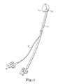
- FIG. 1illustrates an exemplary prior art catheter 11 with mold or balloon 13 located on the distal end.
- biomaterial 23is delivered to the mold 13 through the catheter 11 .
- Secondary tube 11 ′evacuates air from the mold 13 before, during and/or after the biomaterial 23 is delivered.
- the secondary tube 11 ′can either be inside or outside the catheter 11 .
- the present inventionrelates to an intervertebral prosthesis and method for forming an intervertebral prosthesis located in an intervertebral disc space.
- a retention structure and an in situ curable biomaterialcombine in situ to form the intervertebral prosthesis.
- the present method and prosthesiscan be used, for example, to implant a prosthetic disc nucleus using minimally invasive techniques that leave the surrounding disc tissue substantially intact or to implant a prosthetic total disc.
- the phrase intervertebral disc prosthesisis used generically to refer to both of these variations.
- One embodimentis directed to an assembly for the in situ formation of a prosthesis in an intervertebral disc space between adjacent vertebrae of a patient.
- At least one retention structureis located in the intervertebral disc space.
- a distal end of at least a first lumenis located proximate the at least one retention structure.
- One or more in situ curable biomaterialsare delivered to the intervertebral disc space through the first lumen and into engagement with the retention structure.
- the curable biomaterialpreferably adheres to and is at least partially captured by the retention structure. Consequently, the retention structure serves to retain at least a portion of the biomaterial in the intervertebral disc space.
- the at least partially cured biomaterial and the at least one retention structurecooperate to comprise the prosthesis.
- the retention structureincludes a band with openings opposite end plates of the adjacent vertebrae.
- the bandis preferably oriented perpendicular relative to an axis of the spine to restrain the biomaterial from creating excessive pressure on the annular walls.
- the retention structureincludes one or more collapsed retention structures adapted to expand when located in the intervertebral disc space. In another embodiment, the retention structure expands during delivery of the curable biomaterial.
- the retention structurecan be a discrete member or a plurality of retention structures adapted to be delivered sequentially through a lumen into the intervertebral disc space.
- the retention structurecan be expandable and/or reorientable.
- the retention structureis adapted to be assembled within the intervertebral disc space.
- the retention structureoptionally includes a plurality of interlocking members that are assembled in situ.
- the retention structurecomprises a plurality of magnetic members that are assembled in situ.
- the retention structurecan be one or more inflatable members, woven or non-woven mesh, or coiled or kinked members.
- the retention structurepreferably includes a plurality of tension and compression members.
- the retention structuremay include one or more of individual strands, coils, woven or non-woven webs, open cell foams, closed cell foams, combination of open and closed cell foams, scaffolds, cotton-ball fiber matrix, or a generally honeycomb retention structure.
- the retention structureincludes a plurality of interconnected cavities. Fluid flow devices interposed between at least some of the interconnected cavities selectively control the flow of biomaterial into at least some of the cavities.
- the retention structureincludes a plurality of discrete cavities at least a portion of which are at least partially filled with biomaterial.
- the at least partially cured biomaterialpreferably substantially encapsulates the retention structure.
- the retention structure when in the intervertebral disc spacepreferably comprises at least one cross-sectional area greater than a diameter of an opening in the lumen.
- the distal end of the lumenis optionally coupled to at least one retention structure.
- the lumenis optionally releasably attached to the retention structure.
- at least one valveis provided to retain the biomaterial in the cavity after the lumen is removed.
- One or more of the retention structure or the biomaterialoptionally include a bioactive agent.
- at least a portion of an anatomical annuluscontains the retention structure and the curable biomaterial.
- a moldoptionally contains the retention structure and the curable biomaterial. The mold can be a balloon or a porous envelope.
- the present inventionis also directed to a method for the in situ formation of a prosthesis in an intervertebral disc space between adjacent vertebrae of a patient.
- the methodincludes locating at least one retention structure in the intervertebral disc space.
- a distal end of at least a first lumenis located proximate at least one retention structure.
- One or more flowable, curable biomaterialsis delivered into the intervertebral disc space through the first lumen.
- the flowable biomaterialengages with the retention structure located in the intervertebral disc space so that the retention structure retains at least a portion of the biomaterial in the intervertebral disc space.
- the at least partially cured biomaterial and the retention structurescooperating to comprise the prosthesis.
- Minimally invasiverefers to a surgical mechanism, such as microsurgical, percutaneous, or endoscopic or arthroscopic surgical mechanism.
- the entire procedureis minimally invasive, for instance, through minimal incisions in the epidermis (e.g., incisions of less than about 6 centimeters, and more preferably less than 4 centimeters, and preferably less than about 2 centimeters).
- the procedureis minimally invasive only with respect to the annular wall and/or pertinent musculature, or bony structure.
- Such surgical mechanismare typically accomplished by the use of visualization such as fiber optic or microscopic visualization, and provide a post-operative recovery time that is substantially less than the recovery time that accompanies the corresponding open surgical approach. Background on minimally invasive surgery can be found in German and Foley, Minimal Access Surgical Techniques in the Management of the Painful Lumbar Motion Segment, 30 SPINE 16S, n. S52-S59 (2005).
- Retention structuregenerally refers to the portion or portions of the present invention used to receive, constrain, shape and/or retain a flowable biomaterial in the intervertebral disc space during curing the biomaterial in situ.
- a retention structuremay include or rely upon natural tissues (such as the annular shell of an intervertebral disc or the end plates of the adjacent vertebrae) for at least a portion of its conformation or function.
- the retention structuremay form a fully enclosed cavity or chamber or may rely on natural tissue for a portion thereof.
- the retention structureis responsible, at least in part, for determining the position and final dimensions of the cured prosthetic implant.
- the retention structurecan itself become integral to the body of the cured biomaterial.
- the retention structuremay be used in combination with a mold.
- Moldgenerally refers to a flexible member including at least one cavity for the receipt of biomaterial and at least one lumen to that cavity. Multiple molds, either discrete or connected, may be used in some embodiments. Some or all of the material used to form the mold will generally be retained in situ, in combination with the cured biomaterial, while some or the entire lumen will generally be removed upon completion of the procedure.
- the mold and/or lumenscan be biodegradable or bioresorbable. Examples of biodegradable materials can be found in U.S. Publication Nos. 2005-0197422; 2005-0238683; and 2006-0051394, the disclosures of which are hereby incorporated by reference.
- the moldcan be an impermeable, semi-permeable, or permeable membrane.
- the moldis a highly permeable membrane, such as for example a woven or non-woven mesh or other durable, loosely woven fabrics.
- the mold and/or biomaterialcan include or be infused with drugs, pH regulating agents, pain inhibitors, and/or growth stimulants.
- Biomaterialgenerally refers to a material that is capable of being introduced to the site of a joint and cured to provide desired physical-chemical properties in vivo.
- the termwill refer to a material that is capable of being introduced to a site within the body using minimally invasive means, and cured or otherwise modified in order to cause it to be retained in a desired position and configuration.
- biomaterialsare flowable in their uncured form, meaning they are of sufficient viscosity to allow their delivery through a lumen of on the order of about 1 mm to about 10 mm inner diameter, and preferably of about 2 mm to about 6 mm inner diameter.
- Such biomaterialsare also curable, meaning that they can be cured or otherwise modified, in situ, at the tissue site, in order to undergo a phase or chemical change sufficient to retain a desired position and configuration.
- the method and apparatus of the present inventionuses one or more discrete access points or annulotomies into the intervertebral disc space, and/or through the adjacent vertebrae.
- the annulotomiesfacilitate performance of the nuclectomy, imaging or visualization of the procedure, delivery of the retention structure and biomaterial through one or more lumens, drawing a vacuum on a mold before, during and/or after delivery of the biomaterial, and securing the prosthesis in the intervertebral disc space during and after delivery of the biomaterial.
- FIG. 1is an exemplary prior art catheter and mold.
- FIG. 2is a schematic illustration of various entry paths for use in accordance with the present invention.
- FIGS. 3A and 3Bare cross-sectional views of an annulus containing a mold assembly with one or more valves in accordance with the present invention.
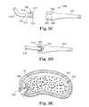
- FIGS. 3C and 3Dare side sectional views of a mold assembly including a connector assembly in accordance with the present invention.
- FIG. 3Eis a cross-sectional view of the mold assembly of FIGS. 3C and 3D implanted in a patient.
- FIGS. 4A and 4Bare cross-sectional views of an annulus containing a mold assembly with an alternate valves in accordance with the present invention.
- FIGS. 5A and 5Bare cross-sectional views of an annulus containing a mold assembly with alternate valves in accordance with the present invention.
- FIGS. 6A and 6Bare cross-sectional views of an annulus containing a retention structure in the form of bands in accordance with the present invention.
- FIGS. 6C and 6Dare cross-sectional views of an annulus containing a mold assembly comprising a retention structure in accordance with the present invention.
- FIGS. 7A and 7Bare cross-sectional views of an annulus containing a prosthesis with an expandable retention structure in accordance with the present invention.
- FIG. 8is a cross-sectional view of an annulus containing a prosthesis with an expandable retention structure in a mold in accordance with the present invention.
- FIG. 9is a cross-sectional view of an annulus containing a prosthesis with an alternate expandable retention structure in accordance with the present invention.
- FIGS. 10A and 10Bare cross-sectional views of an annulus containing a prosthesis with a plurality of helical coils assembled into a retention structure in accordance with the present invention.
- FIGS. 11A and 11Bare cross-sectional views of an annulus containing a prosthesis with a plurality of spherical retention structures in accordance with the present invention.
- FIG. 12is a cross-sectional view of an annulus containing a prosthesis with an assembled retention structure in accordance with the present invention.
- FIG. 13is a cross-sectional view of an annulus containing a prosthesis with an alternate assembled retention structure in accordance with the present invention.
- FIG. 14is a cross-sectional view of an annulus containing a prosthesis with a fibrous retention structure in accordance with the present invention.
- FIG. 15Ais a cross-sectional view of an annulus containing a prosthesis with an expandable honeycomb retention structure in accordance with the present invention.
- FIGS. 15B and 15Care side and top sectional views of an annulus containing a prosthesis with an alternate expandable honeycomb structure in accordance with the present invention.
- FIG. 16is a cross-sectional view of an annulus containing a mold assembly with multiple molds and a pressure activated retention structure in accordance with the present invention.
- FIGS. 17A and 17Bare cross-sectional views of an annulus containing variations of the mold assembly of FIG. 16 .
- FIGS. 18A and 18Bare cross-sectional views of an annulus containing a mold assembly with multiple molds and an alternate pressure activated retention structure in accordance with the present invention.
- FIG. 18Cis a cross-sectional view of the mold assembly of FIGS. 18A and 18B used in a mono-portal application in accordance with the present invention.
- FIGS. 19A and 19Bare cross-sectional views of an annulus containing a mold assembly with patterned radiopaque markers in accordance with the present invention.
- FIGS. 20A and 20Bare cross-sectional views of an annulus containing a mold assembly with an alternate patterned radiopaque markers in accordance with the present invention.
- FIG. 21is a cross-sectional view of an annulus containing a pair of nested molds in accordance with the present invention.
- FIG. 22is a perspective view of the present mold assembly separating adjacent transverse processes in accordance with the present invention.
- FIG. 23is a perspective view of the present mold assembly separating adjacent spinous processes in accordance with the present invention.
- FIG. 2is a cross-sectional view of a human body 20 showing various access paths 22 through 38 to the intervertebral disc 40 for performing the method of the present invention.
- the posterior paths 22 , 24extend either between superior and inferior transverse processes 42 , or between the laminae (interlaminar path) on either side of the spinal cord 44 .
- the posterolateral paths 26 , 28are also on opposite sides of the spinal cord 44 but at an angle of about 35-45 degrees relative to horizontal relative to the posterior paths 22 , 24 .
- the lateral paths 30 , 32extend through the side of the body.
- the anterior path 38 and anterolateral path 34extend past the aorta iliac artery 46 , while the anterolateral path 36 is offset from the inferior vena cava, iliac veins 48 .
- the aorta and vena cavasplit at the L4 vertebral body.
- the approachis typically a midline anterior approach.
- the approachmay be either midline anterior or anterolateral, depending on the patient anatomy and how easy it is to retract the vessels.
- the anterior approachis deemed a midline approach and the anterolateral approach is deemed an angled approach offset from the midline anterior approach.
- the present method and apparatususe one or more of the access paths 22 through 38 . While certain of the access paths 22 through 38 may be preferred depending on a number of factors, such as the nature of the procedure, any of the access paths can be used with the present invention.
- delivery catheter instrumentsare positioned along two or more of the access paths 22 through 38 to facilitate preparation of the intervertebral disc 40 .
- Preparationincludes, for example, formation of two or more annulotomies through the annular wall, removal of some or all of the nucleus pulposus to form a nuclear cavity, imaging of the annulus and/or the nuclear cavity, and positioning of the present multi-lumen mold in the nuclear cavity.
- the present multi-lumen moldis positioned in the intervertebral disc 40 without use of delivery catheters.
- FIG. 3Aillustrates one embodiment of a mold assembly 50 in accordance with the present invention.
- the mold assembly 50includes lumen 52 fluidly coupled to mold 54 .
- valve 56is provided at the interface between the lumen 52 and the mold 54 .
- valve 58is optionally located at a separate location on the mold 54 .
- the method of using the present mold assembly 50involves forming an annulotomy 60 at a location in the annulus 62 .
- the nucleus pulposus 64 located in the disc space 66is preferably substantially removed to create a nuclear cavity 68 . As illustrated in FIG. 3A , some portion of the nucleus pulposus 64 may remain in the nuclear cavity 68 after the nuclectomy.
- the mold assembly 50is then inserted through the annulotomy 60 so that the mold 54 is positioned in the nuclear cavity 68 .
- biomaterial 70is delivered through the lumen 52 into the mold 54 .
- the valves 56 and 58are preferably check valves that are forced into the closed position by the pressure of the biomaterial 70 .
- the lumen 52is detached from the mold 54 removed from the annulotomy 60 .
- the valve 56permits the lumen 52 to be separated and removed before the biomaterial 70 has cured.
- one or more of the mold 54 , the valves 56 , 58 , and/or the lumens 52have radiopaque properties that facilitate imaging of the prosthesis 72 being formed.
- the lumen 52is releasably attached to the valve 56 to facilitate removal.
- the lumen 52is threaded to the valve 56 .
- a quick release interfaceis used to attach the lumen 52 to the valve 56 .
- FIGS. 3C and 3Dare assembly views of a mold assembly 500 with a connection assembly 502 recessed in the mold 504 in accordance with the present invention.
- Open end 506 of the mold 504is inserted into sleeve 508 .
- the connector assembly 502is then coupled to the sleeve 508 .
- the open end 506is secured between the sleeve 508 and connector assembly 502 .
- distal end of the connector assembly 502includes a mechanical interface 510 that mechanically couples with the sleeve 508 .
- the connector assembly 502can be coupled to the open end 506 of the mold 504 and the sleeve 508 using a variety of techniques, such as adhesives, mechanical interlocks, fasteners, and the like.
- the exposed end 512 of the connector assembly 502preferably includes a mechanical interlock 514 , such as for example internal threads, that couple with a corresponding interlock 516 , such as external threads, on the lumen 518 .
- a mechanical interlock 514such as for example internal threads
- a corresponding interlock 516such as external threads
- the biomaterial 70is retained in the mold by valve 520 preferably located in the connector assembly 502 .
- the connector assembly 502 and/or the valve 520are substantially flush with the outer surface of the mold 504 .
- the connector assembly 502may protrude above the outer surface of the mold 504 .
- the lumen 518is preferably removed from the mold assembly 500 before the biomaterial 70 is cured.
- the exposed mechanical interlock 514 on the connector assembly 502can optionally be used to attach a securing device 522 to the prosthesis 524 .
- FIG. 4Aillustrates an alternate mold assembly 80 in accordance with the present invention.
- Mold 82includes a plurality of openings 84 .
- the openings 84can be any shape and a variety of sizes.
- Internal flaps 86are located over the openings 84 .
- biomaterial 70is delivered through lumen 88 to the mold 82 . Pressure from the biomaterial 70 presses the flaps 86 against the openings 84 , substantially sealing the biomaterial 70 within the mold 82 .
- the flaps 86permit any air or biomaterial in the mold 82 to be pushed out through the openings 84 during delivery of the biomaterial 70 . In another embodiment, the flaps 86 to not completely seal the openings 84 until the mold 82 is substantially inflated and pressing against inner surface 92 of the annulus 62 .
- the flaps 86can be constructed from the same or different material than the mold 82 .
- the flaps 86are constructed from a radiopaque material that is easily visible using various imaging technologies.
- the spacing between the flaps 86Prior to the delivery of the biomaterial 70 , such as illustrated in FIG. 4A , the spacing between the flaps 86 indicates that the mold 82 is not inflated.
- the spacing between the flaps 86provides an indication of the shape and position of the intervertebral prosthesis 90 relative to the annulus 62 .
- FIG. 5Aillustrates an alternate mold assembly 100 in accordance with the present invention.
- Mold 102includes a plurality of openings 104 with corresponding external flaps or valves 106 .
- delivery of the biomaterial 70causes the mold 102 to inflate.
- the flaps 106are pressed against the openings 104 by interior surface 108 of the nuclear cavity 68 .
- portion 110 of the biomaterial 70forms a raised structure 112 over some or all of the openings 104 .
- These raised structuresserve to anchor the resulting prosthesis 114 in the nuclear cavity 68 .
- Other examples of raised structuresinclude barbs, spikes, hooks, and/or a high friction surface that can facilitate attachment to soft tissue and/or bone.
- portion 116 of the biomaterial 70optionally escapes from the mold 102 prior to the flaps 106 being pressed against the openings 104 .
- the portion 116 of the biomaterial 70serves to adhere the prosthesis 114 to the inner surface 108 of the annulus 62 .
- the flaps 106may include radiopaque properties.
- FIGS. 6A and 6Billustrate a prosthesis 136 including one or more retention structures 124 , 126 .
- retention structure 124is positioned horizontally between adjacent vertebrae 128 , 130 .
- Retention structure 126is oriented perpendicular to the retention structure.
- Lumen 120is preferably engaged with one or both of the retention structures 124 , 126 .
- the retention structurepreferably limits the amount of pressure the resulting prosthesis 136 places on the annular walls 62 .
- a compressive force placed on the prosthesis 136 by the end plates 132 , 134is directed back towards the end plates, rather than horizontally into the annular wall 62 .
- the retention structurepreferably limits inflation of the mold 122 in the vertical direction.
- the retention structurecan optionally be used to set a maximum disc height or separation between the adjacent vertebrae 128 , 130 when the mold 122 is fully inflated.
- the retention structure 124 , 126are preferably radiopaque. As with the flaps 86 , 106 of FIGS. 4 and 5 , the retention structure 124 , 126 provide an indication of the shape and position of the prosthesis 136 in the intervertebral disc space 138 . As the biomaterial is delivered, the retention structures 124 , 126 are deployed and positioned in accordance with the requirements of the prosthesis 136 . A series of images can be taken of the intervertebral disc space 138 to map the progress of the prosthesis formation. Because the size and width of the retention structure 124 , 126 are known prior to the procedure, the resulting images provide an accurate picture of the position of the prosthesis 136 relative to the vertebrae 128 , 130 .
- the retention structures 124 , 126are used in combination with mold 122 . In an alternate embodiment, one or both of the retention structures 124 , 126 can be located at the interior of the mold 122 . The retention structures 124 , 126 can optionally be attached to the mold 122 .
- FIGS. 6C and 6Dillustrate a retention structure 142 in accordance with the present invention.
- the retention structure 142is preferably positioned horizontally between adjacent vertebrae 128 , 130 .
- the retention structure 142also serves as a mold for retaining at least a portion of the biomaterial 70 .
- the annulus wall 62may also act to retain the biomaterial 70 in the intervertebral disc space.
- the retention structure 142preferably extends to the endplates 132 , 134 so that the biomaterial 70 is substantially retained in center region 144 formed by the retention structure 142 .
- the biomaterial 70extends above and below the retention structure 142 to engage with the endplates 132 , 134 .
- the retention structure 142is open at the top and bottom. In some embodiments, the biomaterial 70 may flow around the outside perimeter of the retention structure 142 .
- FIGS. 7A and 7Billustrate an alternate prosthesis 158 in accordance with the present invention.
- Retention structure 154 configured in a compressed stateis delivered into the nuclear cavity 68 of the annulus 62 through delivery lumen 156 .
- the retention structure 154As best illustrated in FIG. 7B , once the retention structure 154 is released from the delivery lumen 156 , it assumes its original expanded shape within the nuclear cavity 68 .
- the biomaterial 70is delivered to the nuclear cavity 68 , where it flows into and around the retention structure 154 .
- the retention structure 154serves to retain at least a portion of the biomaterial in the nuclear cavity 68 by surface tension, adhesion, mechanical capture, friction, viscosity, and a variety of other mechanisms.
- the retention structure 154is deployed by the pressure of the biomaterial 70 being delivered into the nuclear cavity 68 .
- the retention structure 154is a mesh woven to form a generally tubular structure.
- the mesh 154can be constructed from a variety of metal, polymeric, biologic, and composite materials suitable for implantation in the human body.
- the meshoperates primarily as a tension member within the prosthesis 158 .
- the retention structure 154is configured to act as both a tension and compression member within the prosthesis 158 .
- the retention structure 154or portions thereof, are constructed from a radiopaque material.
- the radiopaque elements of the retention structure 154provide a grid or measuring device that is readily visible using conventional imaging techniques.
- the retention structure 154thus provides a way to determine the shape, volume, dimensions, and position of the prosthesis 158 in the annular cavity 68 .
- FIG. 8illustrates an alternate prosthesis 160 with an internal retention structure 162 having a shape generally corresponding to the nuclear cavity 68 .
- the retention structure 162is compressed within the delivery lumen 156 (see FIG. 7A ) and delivered into mold 164 located in the nuclear cavity 68 .
- the retention structure 162can operate as a tension and/or compression member within the prosthesis 160 .
- FIG. 9illustrates an alternate prosthesis 170 in accordance with the present invention.
- Retention structure 172is again positioned in the nuclear cavity 68 in a compressed configuration through a delivery lumen 156 (see FIG. 7A ).
- the retention structure 172is preferably constructed of a shape memory alloy (SMA), such as the nickel-titanium alloy Nitinol or of an elastic memory polymer that assumes a predetermined shape once released from the delivery lumen 156 or once a certain temperature is reached, such as for example the heat of the body.
- SMAshape memory alloy
- the retention structure 172has radiopaque properties which can be used to facilitate imaging of the prosthesis 170 .
- the retention structure 172is a mold configured with a coil shape. When inflated with biomaterial 70 , the mold forms a coil-shaped retention structure. Additional biomaterial 70 is preferably delivered around the coil structure 172 .
- FIGS. 10A and 10Billustrate an alternate prosthesis 188 in accordance with the present invention.
- a plurality of discrete helical retaining structures 182are delivered through a delivery lumen 184 into the annular cavity 68 .
- the helical retaining structures 182intertwine and become entangled within the annular cavity 68 .
- the helical retaining structures 182are rotated during insertion to facilitate engagement with the retaining structures 182 already in the annular cavity 68 .
- these retaining structures 182can be kinked strands, which when compressed have a generally longitudinal orientation to provide easy delivery through the lumen 184 .
- the retaining structures 182are permitted to expand or reorient.
- the cross-sectional area of the retaining structures 182 in the expanded or reoriented stateis preferably greater than the diameter of the lumen 184 , so as to prevent ejection during delivery of the biomaterial 70 .
- the plurality of retaining structures 182are preferably discrete structures that act randomly and can be positioned independently.
- the discrete retaining structures 182 of the present inventioncan be delivered sequentially and interlocked or interengaged in situ. Alternatively, groups of the retaining structures 182 can be delivered together.
- the retaining structures 182can act as spring members to provide additional resistance to compression and as tension members within the prosthesis 188 . Some or all of the helical retaining structures 182 preferably have radiopaque properties to facilitate imaging of the prosthesis 188 .
- FIGS. 11A and 11Billustrate an alternate prosthesis 200 in accordance with the present invention.
- a plurality of retaining structures 204are delivered into the nuclear cavity 68 .
- Biomaterial 70is then delivered to the nuclear cavity 68 .
- the retention structures 204assist in holding the biomaterial 70 in place.
- the retention structures 204typically arrange themselves randomly within the intervertebral disc space 202 .
- the retention structures 204are a plurality of spherical members 206 .
- the spherical members 206flow and shift relative to each other within the intervertebral disc space 202 .
- the spherical members 206are constructed from metal, ceramic, and/or polymeric materials.
- the spherical members 206can also be a multi-layered structure, such as for example, a metal core with a polymeric outer layer.
- the spherical members 206are hollow shells with openings into which the biomaterial 70 can flow.
- the biomaterial 70fills the hollow interior of the spherical members 206 and bonds adjacent spherical members 206 to each other.
- the spherical members 206have magnetic properties so they clump together within the intervertebral disc space 202 before the biomaterial 70 is delivered. Some or all of the spherical members 206 optionally have radiopaque properties.
- FIG. 12is a side sectional view of an intervertebral disc space 138 containing prosthesis 210 in accordance with the present invention.
- a plurality of polyhedron retention structures 212are delivered into the intervertebral disc space 138 through lumen 216 .
- the retention structurecan be pyramidal, tetrahedrons, and the like.
- the pyramidal retention structures 212have magnetic properties causing them to bind to each other within the intervertebral disc space 138 .
- the pyramidal retention structures 212include a plurality of holes or cavities into which the biomaterial 70 flows, securing the retention structures 212 relative to each other and relative to the prosthesis 210 .
- FIG. 13is a side sectional view of an intervertebral disc space 138 with prosthesis 224 having coiled or loop shaped retention structures 220 in accordance with the present invention.
- the retention structures 220can be compressed for delivery through the lumen 222 , and allowed to expand once inside the nuclear cavity 68 .
- Biomaterial 70is then injected to secure the relative position of the retention structures 220 within the prosthesis 224 .
- the retention structures 220are preferably constructed from a spring metal that helps maintain the separation between the adjacent vertebrae 128 , 130 .
- the retention structures 220are resilient and flex when loaded.
- the retention structures 220are substantially rigid in at least one direction, while being compliant in another direction to permit insertion through the lumen 222 .
- the retention structures 220optionally define a minimum separation between the adjacent vertebrae 128 , 130 .
- the retention structures 220can operate as tension and/or compression members.
- FIG. 14is a side sectional view of an alternate prosthesis 258 in accordance with the present invention.
- a plurality of reinforcing fibers 252are delivered into the intervertebral disc space 254 through lumen 256 .
- the biomaterial 70is then delivered and secures the relative position of the reinforcing fibers 252 within the intervertebral disc space 138 .
- the reinforcing fibers 252can be in the form of individual strands, coils, woven or non-woven webs, open cell foams, closed cell foams, combination of open and closed cell foams, scaffolds, cotton-ball fiber matrix, or a variety of other structures.
- the reinforcing fibers 252can be constructed from metal, ceramic, polymeric materials, or composites thereof.
- the reinforcing fibers 252can operate as tension and/or compression members within prosthesis 258 .
- FIG. 15Ais a side sectional view of an alternate prosthesis 278 in accordance with the present invention.
- a three-dimensional honeycomb structure 272is compressed and delivered into the intervertebral disc space 274 through the lumen 276 .
- the biomaterial 70is delivered, fixing the honeycomb structure 272 in the illustrated configuration.
- the delivery of the biomaterialexpands or inflates the honeycomb structure 272 .
- the biomaterial 70flows around and into the honeycomb structure 272 providing a highly resilient prosthesis 278 .
- the honeycomb structure 272still retains its capacity to flex along with the biomaterial 70 when compressed by the adjacent vertebrae 128 , 130 .
- the honeycomb structure 272can be constructed from a plurality of interconnected tension and/or compression members.
- the honeycomb structureis an open cell foam.
- the honeycomb structure 272has fluid flow devices, such as for example pores, holes of varying diameter or valves, interposed between at least some of the interconnected cavities 280 .
- the fluid flow devicesselectively controlling the flow of biomaterial 70 into at least some of the cavities 280 or filling the cavities 280 differentially, thus combining the different mechanical properties of the honeycomb structure 272 with the biomaterial 70 in an adaptable manner.
- the generally honeycomb structure 272can optionally be combined with open or closed cell foam.
- FIGS. 15B and 15Care side and top sectional views of a prosthesis 282 with a plurality of three-dimensional honeycomb structures 284 A, 284 B (referred to collectively as “ 284 ”) in accordance with the present invention.
- the honeycomb structures 284are constructed so that the inflow of biomaterial 70 can be selectively directed to certain cavities 286 .
- more than two honeycomb structures 284 A, 284 Bcan optionally be used.
- holes interconnecting adjacent cavities 286can be selectively opened or closed before the honeycomb structures 284 are inserted into the patient.
- a plurality of lumens 288 A, 288 B, 288 C, . . .(referred to collectively as “ 288 ”) are provided that are each connected to a different cavity 286 .
- One or more of the lumens 288can also be used to evacuate the annular cavity 68 .
- Selective delivery of the biomaterial 70 into the honeycomb structures 284can be used to create a variety of predetermined internal shapes. Using a plurality of lumens 288 permits different biomaterials 70 A, 70 B, 70 C, . . . to be delivered to different cavities 286 within the honeycomb structure 284 .
- the biomaterials 70 A, 70 B, 70 C, . . .can be selected based on a variety of properties, such as mechanical or biological properties, biodegradability, bioabsorbability, ability to delivery bioactive agents.
- bioactive agentrefers to cytokines and preparations with cytokines, microorganisms, plasmids, cultures of microorganisms, DNA-sequences, clone vectors, monoclonal and polyclonal antibodies, drugs, pH regulators, cells, enzymes, purified recombinant and natural proteins, growth factors, and the like.
- FIG. 16illustrates an alternate mold assembly 300 in accordance with the present invention.
- two annulotomies 60 A, 60 Bare formed in the annulus 62 .
- the mold assembly 300is threaded through one of the annulotomies so that the lumens 302 , 304 each protrude from annulotomies 60 A, 60 B, respectively.
- Lumen 302is fluidly coupled to mold 306 while lumen 304 is fluidly coupled with mold 308 .
- Retention structure 310is attached to molds 306 , 308 at the locations 312 , 314 , respectively.
- FIG. 17Ais a side sectional view of the mold assembly 300 of FIG. 16 implanted between adjacent vertebrae 128 , 130 .
- Biomaterial 70is delivered to the molds 306 , 308 , which applies opposing compressive forces 316 on the retention structure 310 .
- the retention structure 310is a coil, loop, or bend (arc) of resilient material, such as a memory metal, spring metal, and the like.
- the resulting prosthesis 312includes a pair of molds 306 , 308 containing a cured biomaterial 70 holding the retention structure 310 against adjacent end plates 132 , 136 of the vertebrae 128 , 130 respectively.
- the retention structurecan serve to resist compression of the prosthesis 312 or to establish a minimum separation between the adjacent end plates 132 , 134 .
- FIG. 17Bis an alternate embodiment of the mold assembly 300 of FIG. 16 .
- retention structure 310includes a series of fold lines or hinges 318 . Expansion of the molds 306 , 308 with biomaterial 70 generates forces 316 that converts the generally flat retention structure 310 (see FIG. 16 ) into the shaped retention structure 322 illustrated in FIG. 17B .
- the hinge 318could be facing the molds 306 , 308 rather than the endplates.
- delivery of the biomaterial 70deploys the retention structure 310 to an expanded configuration.
- FIGS. 18A and 18Billustrate an alternate mold assembly 350 in accordance with the present invention.
- Lumens 352 , 354extend into the annulus 62 through different annulotomies 60 A, 60 B.
- Lumen 352is fluidly coupled with mold 356 and lumen 354 is fluidly coupled with mold 358 .
- Reinforcing mesh structure 364is connected to the molds 356 , 358 at locations 360 , 362 , respectively.
- biomaterial 70is delivered to the molds 356 , 358 causing the retention structure 364 to be compressed and/or stretched within the nuclear cavity 68 .
- additional biomaterial 70can optionally be delivered into the nuclear cavity 68 proximate the retention structure 364 .
- the same or a different biomaterial 70 Aflows around and into the retention structure 364 .
- the biomaterial 70 Abonds the retention structure 364 to the annulus 62 .
- the resulting prosthesis 366has three distinct regions of resiliency. The areas of varying resiliency can be tailored for implants that would be implanted via different surgical approaches, as well as various disease states.
- the retention structure 364optionally includes radiopaque properties. A series of images taken during delivery of the biomaterial 70 illustrates the expansion and position of the prosthesis 366 in the nuclear cavity 68 .
- FIG. 18Cis an alternate configuration of the mold assembly 350 for use with mono-portal applications in accordance with the present invention.
- Lumens 352 , 354extend into the annulus 62 through a single annulotomy 60 .
- Lumen 352is fluidly coupled with mold 356 and lumen 354 is fluidly coupled with mold 358 .
- Reinforcing mesh structure 364is connected to the molds 356 , 358 at locations 360 , 362 , respectively.
- delivery of the biomaterial 70causing the retention structure 364 to be compressed and/or stretched within the nuclear cavity 68 .
- Additional biomaterial 70 Acan optionally be delivered into the nuclear cavity 68 proximate the retention structure 364 .
- FIGS. 19A and 19Bare side sectional views of mold assembly 400 in accordance with the present invention.
- the mold 402includes a plurality of radiopaque markers 404 .
- the radiopaque markers 404are arranged in a predetermined pattern around the perimeter of the mold 402 .
- the spacing 406 between the adjacent radiopaque markers 404increases.
- a series of imagescan be generated showing the change in the spacing between the radiopaque markers 404 . Because the spacing between the radiopaque markers 404 is known prior to delivery of the biomaterial, it is possible to calculate the shape and position of the prosthesis 408 illustrated in FIG. 19B using conventional imaging procedures.
- FIGS. 20A and 20Billustrate an alternate mold assembly 420 in accordance with the present invention.
- Mold 422includes a plurality of radiopaque strips 424 located strategically around its perimeter. When the mold 422 is inflated with biomaterial, the spacing 426 between the radiopaque strips 424 changes, providing an easily imagable indication of the shape and position of the prosthesis 428 in the intervertebral disc space 138 .
- FIG. 21illustrates an alternate mold assembly 450 in accordance with the present invention.
- Inner mold 452is fluidly coupled to lumen 454 .
- Outer mold 456is fluidly coupled to lumen 458 .
- Biomaterialis delivered through the lumen 454 into the inner mold 452 .
- a radiopaque fluidis preferably delivered to the space 460 between the inner mold 452 and the outer mold 456 .
- the radiopaque material 462 located in the space 460is expelled from the nuclear cavity 68 through the lumen 458 .
- a series of images of the annulus 62will show the progress of the biomaterial 70 expanding the inner mold 452 within the nuclear cavity 68 and the flow of the radiopaque fluid 462 out of the space 460 through the lumen 458 .
- a biological material or bioactive agentis injected into the space 460 through the delivery lumen 458 .
- the outer mold 456is sufficiently porous to permit the bioactive agent to be expelled into the annular cavity 68 , preferably over a period of time.
- One of the molds 452 , 456optionally includes radiopaque properties.
- the mold 456is preferably biodegradable or bioresorbable with a half life greater than the time required to expel the bioactive agents.
- one or more retention structures 464is located in the space 460 between the inner and outer molds 452 , 456 .
- the retention structure 464may be a woven or non-woven mesh impregnated with the bioactive agent.
- the retention structure 464 and the outer mold 456are a single structure, such as a reinforcing mesh impregnated with the bioactive agent.
- the outer mold 456may be a stent-like structure, preferably coated with one or more bioactive agents.
- FIGS. 22 and 23illustrate use of a mold assembly 550 to maintain the separation between spinous process 552 and/or transverse processes 554 on adjacent vertebrae 556 , 558 in according with the present method and apparatus.
- the mold assembly 550may be used alone or in combination with an intervertebral mold assembly, such as discussed herein.
- the mold assembly 550can also be used to separate the superior articulating process and inferior articulating process, more commonly referred to as the facet joint, on adjacent vertebrae.
- the mold 560preferable includes extension 562 , 564 that couple or engage with the spinous process or transverse processes 552 , 554 .
- Center portion 566acts as a spacer to maintain the desired separation.
- the mold assemblyhas an H-shaped or figure-8 shaped cross section to facilitate coupling with the various facets on the adjacent vertebral bodies. Attachment of the molds 550 or 560 to the spinous or transverse processes may be further facilitated using sutures, cables, ties, rivets, screws, clamps, sleeves, collars, adhesives, or the like. Any of the mold assemblies and retention structures disclosed herein can be used with the mold assembly 550 .
- any of the features disclosed hereincan be combined with each other and/or with features disclosed in commonly assigned U.S. patent application Ser. No. 11/268,786, entitled Multi-Lumen Mold for Intervertebral Prosthesis and Method of Using Same, filed Nov. 8, 2005, which is hereby incorporated by reference.
- Any of the molds and/or lumens disclosed hereincan optionally be constructed from biodegradable or bioresorbable materials.
- the lumens disclosed hereincan be constructed from a rigid, semi-rigid, or pliable high tensile strength material.
- the various components of the mold assemblies disclosed hereinmay be attached using a variety of techniques, such as adhesives, solvent bonding, mechanical deformation, mechanical interlock, or a variety of other techniques.
- the mold assembly of the present inventionis preferably inserted into the nuclear cavity 68 through a catheter, such as illustrated in commonly assigned U.S. patent application Ser. No. 11/268,876 entitled Catheter Holder for Spinal Implants, filed Nov. 8, 2005, which is hereby incorporated by reference.
- the present mold assembliescan also be used with the method of implanting a prosthetic nucleus disclosed in a commonly assigned U.S. patent application Ser. No. 11/268,856, entitled Lordosis Creating Nucleus Replacement Method and Apparatus, filed on Nov. 8, 2005, which are incorporated herein by reference.
- the mold assemblies and methods of the present inventioncan also be used to repair other joints within the spine such as the facet joints, as well as other joints of the body, including diarthroidal and amphiarthroidal joints.
- suitable diarthroidal jointsinclude the ginglymus (a hinge joint, as in the interphalangeal joints and the joint between the humerus and the ulna); throchoides (a pivot joint, as in superior radio-ulnar articulation and atlanto-axial joint); condyloid (ovoid head with elliptical cavity, as in the wrist joint); reciprocal reception (saddle joint formed of convex and concave surfaces, as in the carpo-metacarpal joint of the thumb); enarthrosis (ball and socket joint, as in the hip and shoulder joints) and arthrodia (gliding joint, as in the carpal and tarsal articulations).
- the present mold apparatuscan also be used for a variety of other procedures, including those listed above.
- the present mold assemblycan also be used to modify the interspinous or transverse process space.
- the moldcan operate as a spacer/distractor between the inferior and superior spinous processes, thus creating a local distraction and kyphosis of wanted.
- the theory behind these implantsis that they expand the intervertebral foramen and thereby relieve pressure on the nerve root and spinal cord.
- the present injectable prosthesisis adapted to the individual anatomy and clinical situation of the patient, without the need for multiple implant sizes.
Landscapes
- Health & Medical Sciences (AREA)
- Orthopedic Medicine & Surgery (AREA)
- Neurology (AREA)
- Life Sciences & Earth Sciences (AREA)
- Surgery (AREA)
- Engineering & Computer Science (AREA)
- Biomedical Technology (AREA)
- General Health & Medical Sciences (AREA)
- Veterinary Medicine (AREA)
- Heart & Thoracic Surgery (AREA)
- Public Health (AREA)
- Animal Behavior & Ethology (AREA)
- Molecular Biology (AREA)
- Medical Informatics (AREA)
- Nuclear Medicine, Radiotherapy & Molecular Imaging (AREA)
- Chemical & Material Sciences (AREA)
- Dispersion Chemistry (AREA)
- Cardiology (AREA)
- Oral & Maxillofacial Surgery (AREA)
- Transplantation (AREA)
- Vascular Medicine (AREA)
- Prostheses (AREA)
Abstract
Description
Claims (28)
Priority Applications (3)
| Application Number | Priority Date | Filing Date | Title |
|---|---|---|---|
| US12/203,727US8092536B2 (en) | 2006-05-24 | 2008-09-03 | Retention structure for in situ formation of an intervertebral prosthesis |
| US12/338,544US20090131939A1 (en) | 2006-05-24 | 2008-12-18 | Inflatable mold for maintaining posterior spinal elements in a desired alignment |
| PCT/US2009/053768WO2010027622A1 (en) | 2008-09-03 | 2009-08-13 | Retention structure for in situ formation of an intervertebral prosthesis |
Applications Claiming Priority (2)
| Application Number | Priority Date | Filing Date | Title |
|---|---|---|---|
| US11/420,055US20070276491A1 (en) | 2006-05-24 | 2006-05-24 | Mold assembly for intervertebral prosthesis |
| US12/203,727US8092536B2 (en) | 2006-05-24 | 2008-09-03 | Retention structure for in situ formation of an intervertebral prosthesis |
Related Parent Applications (1)
| Application Number | Title | Priority Date | Filing Date |
|---|---|---|---|
| US11/420,055Continuation-In-PartUS20070276491A1 (en) | 2006-05-24 | 2006-05-24 | Mold assembly for intervertebral prosthesis |
Related Child Applications (1)
| Application Number | Title | Priority Date | Filing Date |
|---|---|---|---|
| US11/420,055Continuation-In-PartUS20070276491A1 (en) | 2006-05-24 | 2006-05-24 | Mold assembly for intervertebral prosthesis |
Publications (2)
| Publication Number | Publication Date |
|---|---|
| US20090012618A1 US20090012618A1 (en) | 2009-01-08 |
| US8092536B2true US8092536B2 (en) | 2012-01-10 |
Family
ID=41263617
Family Applications (1)
| Application Number | Title | Priority Date | Filing Date |
|---|---|---|---|
| US12/203,727Expired - Fee RelatedUS8092536B2 (en) | 2006-05-24 | 2008-09-03 | Retention structure for in situ formation of an intervertebral prosthesis |
Country Status (2)
| Country | Link |
|---|---|
| US (1) | US8092536B2 (en) |
| WO (1) | WO2010027622A1 (en) |
Cited By (28)
| Publication number | Priority date | Publication date | Assignee | Title |
|---|---|---|---|---|
| US20110015680A1 (en)* | 2002-08-27 | 2011-01-20 | Warsaw Orthopedic, Inc. | Systems and methods for intravertebral reduction |
| US20120116514A1 (en)* | 2002-11-05 | 2012-05-10 | Kuslich Stephen D | Semi-biological intervertebral disc replacement system |
| US9433404B2 (en) | 2012-10-31 | 2016-09-06 | Suture Concepts Inc. | Method and apparatus for closing fissures in the annulus fibrosus |
| US9545321B2 (en) | 2013-03-14 | 2017-01-17 | Spinal Stabilization Technologies Llc | Prosthetic spinal disk nucleus |
| US9700425B1 (en) | 2011-03-20 | 2017-07-11 | Nuvasive, Inc. | Vertebral body replacement and insertion methods |
| US9918849B2 (en) | 2015-04-29 | 2018-03-20 | Institute for Musculoskeletal Science and Education, Ltd. | Coiled implants and systems and methods of use thereof |
| US9949734B2 (en) | 2012-10-31 | 2018-04-24 | Suture Concepts Inc. | Method and apparatus for closing a fissure in the annulus of an intervertebral disc, and/or for effecting other anatomical repairs and/or fixations |
| US10213317B2 (en) | 2017-03-13 | 2019-02-26 | Institute for Musculoskeletal Science and Education | Implant with supported helical members |
| US10314714B2 (en) | 2014-11-04 | 2019-06-11 | Spinal Stabilization Technologies Llc | Percutaneous implantable nuclear prosthesis |
| US10357377B2 (en) | 2017-03-13 | 2019-07-23 | Institute for Musculoskeletal Science and Education, Ltd. | Implant with bone contacting elements having helical and undulating planar geometries |
| US10449051B2 (en) | 2015-04-29 | 2019-10-22 | Institute for Musculoskeletal Science and Education, Ltd. | Implant with curved bone contacting elements |
| US10478312B2 (en) | 2016-10-25 | 2019-11-19 | Institute for Musculoskeletal Science and Education, Ltd. | Implant with protected fusion zones |
| US10492921B2 (en) | 2015-04-29 | 2019-12-03 | Institute for Musculoskeletal Science and Education, Ltd. | Implant with arched bone contacting elements |
| US10512549B2 (en) | 2017-03-13 | 2019-12-24 | Institute for Musculoskeletal Science and Education, Ltd. | Implant with structural members arranged around a ring |
| US10575967B2 (en) | 2015-09-01 | 2020-03-03 | Spinal Stabilization Technologies Llc | Implantable nuclear prosthesis |
| US10603087B2 (en) | 2008-01-14 | 2020-03-31 | Conventus Orthopaedics, Inc. | Apparatus and methods for fracture repair |
| US10667924B2 (en) | 2017-03-13 | 2020-06-02 | Institute for Musculoskeletal Science and Education, Ltd. | Corpectomy implant |
| US10695192B2 (en) | 2018-01-31 | 2020-06-30 | Institute for Musculoskeletal Science and Education, Ltd. | Implant with internal support members |
| US10709570B2 (en) | 2015-04-29 | 2020-07-14 | Institute for Musculoskeletal Science and Education, Ltd. | Implant with a diagonal insertion axis |
| US10786235B2 (en) | 2012-10-31 | 2020-09-29 | Anchor Innovation Medical, Inc. | Method and apparatus for closing a fissure in the annulus of an intervertebral disc, and/or for effecting other anatomical repairs and/or fixations |
| US10918426B2 (en) | 2017-07-04 | 2021-02-16 | Conventus Orthopaedics, Inc. | Apparatus and methods for treatment of a bone |
| US11129727B2 (en) | 2019-03-29 | 2021-09-28 | Medos International Sari | Inflatable non-distracting intervertebral implants and related methods |
| US11596419B2 (en) | 2017-03-09 | 2023-03-07 | Flower Orthopedics Corporation | Plating depth gauge and countersink instrument |
| US11633287B2 (en) | 2014-11-04 | 2023-04-25 | Spinal Stabilization Technologies Llc | Percutaneous implantable nuclear prosthesis |
| US11744710B2 (en) | 2018-09-04 | 2023-09-05 | Spinal Stabilization Technologies Llc | Implantable nuclear prosthesis, kits, and related methods |
| US11793652B2 (en) | 2017-11-21 | 2023-10-24 | Institute for Musculoskeletal Science and Education, Ltd. | Implant with improved bone contact |
| US11951018B2 (en) | 2017-11-21 | 2024-04-09 | Institute for Musculoskeletal Science and Education, Ltd. | Implant with improved flow characteristics |
| US12208011B2 (en) | 2016-10-25 | 2025-01-28 | Institute for Musculoskeletal Science and Education, Ltd. | Implant with multi-layer bone interfacing lattice |
Families Citing this family (18)
| Publication number | Priority date | Publication date | Assignee | Title |
|---|---|---|---|---|
| DE10154163A1 (en)* | 2001-11-03 | 2003-05-22 | Advanced Med Tech | Device for straightening and stabilizing the spine |
| US7955339B2 (en)* | 2005-05-24 | 2011-06-07 | Kyphon Sarl | Low-compliance expandable medical device |
| US20070042326A1 (en)* | 2005-06-01 | 2007-02-22 | Osseous Technologies Of America | Collagen antral membrane expander |
| US20090131939A1 (en)* | 2006-05-24 | 2009-05-21 | Disc Dynamics, Inc. | Inflatable mold for maintaining posterior spinal elements in a desired alignment |
| PL2124831T3 (en) | 2007-03-15 | 2017-03-31 | Ortho-Space Ltd. | Prosthetic devices |
| US8636803B2 (en) | 2009-04-07 | 2014-01-28 | Spinal Stabilization Technologies, Llc | Percutaneous implantable nuclear prosthesis |
| CH701006A2 (en)* | 2009-05-11 | 2010-11-15 | Marcel Dr Med Capaul | Disc pads. |
| US20110190774A1 (en)* | 2009-11-18 | 2011-08-04 | Julian Nikolchev | Methods and apparatus for performing an arthroscopic procedure using surgical navigation |
| US9289307B2 (en)* | 2011-10-18 | 2016-03-22 | Ortho-Space Ltd. | Prosthetic devices and methods for using same |
| US9295479B2 (en) | 2013-03-14 | 2016-03-29 | Spinal Stabilization Technologies, Llc | Surgical device |
| US9308123B2 (en)* | 2013-09-16 | 2016-04-12 | Neuraxis, Llc | Methods and devices for applying localized thermal therapy |
| US8911486B1 (en) | 2013-09-16 | 2014-12-16 | Neuraxis, Llc | Implantable devices for thermal therapy and related methods |
| WO2017046647A1 (en) | 2015-09-18 | 2017-03-23 | Ortho-Space Ltd. | Intramedullary fixated subacromial spacers |
| US9486323B1 (en)* | 2015-11-06 | 2016-11-08 | Spinal Stabilization Technologies Llc | Nuclear implant apparatus and method following partial nuclectomy |
| US10267261B2 (en)* | 2016-08-01 | 2019-04-23 | GM Global Technology Operations LLC | Methods of joining components in vehicle assemblies |
| US11213402B2 (en)* | 2017-01-11 | 2022-01-04 | Loubert S. Suddaby | Endoscopically implantable inflatable interbody fusion device |
| EP3573806A4 (en) | 2017-01-30 | 2019-12-11 | Ortho-Space Ltd. | Processing machine and methods for processing dip-molded articles |
| US11937799B2 (en) | 2021-09-29 | 2024-03-26 | Cilag Gmbh International | Surgical sealing systems for instrument stabilization |
Citations (155)
| Publication number | Priority date | Publication date | Assignee | Title |
|---|---|---|---|---|
| US4545374A (en) | 1982-09-03 | 1985-10-08 | Jacobson Robert E | Method and instruments for performing a percutaneous lumbar diskectomy |
| US4759766A (en)* | 1984-09-04 | 1988-07-26 | Humboldt-Universitaet Zu Berlin | Intervertebral disc endoprosthesis |
| US4834757A (en) | 1987-01-22 | 1989-05-30 | Brantigan John W | Prosthetic implant |
| US4969888A (en) | 1989-02-09 | 1990-11-13 | Arie Scholten | Surgical protocol for fixation of osteoporotic bone using inflatable device |
| US5047055A (en) | 1990-12-21 | 1991-09-10 | Pfizer Hospital Products Group, Inc. | Hydrogel intervertebral disc nucleus |
| US5171281A (en) | 1988-08-18 | 1992-12-15 | University Of Medicine & Dentistry Of New Jersey | Functional and biocompatible intervertebral disc spacer containing elastomeric material of varying hardness |
| US5269797A (en) | 1991-09-12 | 1993-12-14 | Meditron Devices, Inc. | Cervical discectomy instruments |
| US5285795A (en) | 1991-09-12 | 1994-02-15 | Surgical Dynamics, Inc. | Percutaneous discectomy system having a bendable discectomy probe and a steerable cannula |
| US5314432A (en) | 1993-08-05 | 1994-05-24 | Paul Kamaljit S | Lumbar spinal disc trocar placement device |
| US5331975A (en) | 1990-03-02 | 1994-07-26 | Bonutti Peter M | Fluid operated retractors |
| US5395317A (en) | 1991-10-30 | 1995-03-07 | Smith & Nephew Dyonics, Inc. | Unilateral biportal percutaneous surgical procedure |
| US5413576A (en) | 1993-02-10 | 1995-05-09 | Rivard; Charles-Hilaire | Apparatus for treating spinal disorder |
| US5425772A (en) | 1993-09-20 | 1995-06-20 | Brantigan; John W. | Prosthetic implant for intervertebral spinal fusion |
| US5476473A (en) | 1993-01-05 | 1995-12-19 | Richard Wolf Gmbh | Instrument for surgically cutting tissue |
| US5520678A (en) | 1993-11-30 | 1996-05-28 | Richard Wolf Gmbh | Manipulator arm with proximal and distal control balls |
| US5527312A (en) | 1994-08-19 | 1996-06-18 | Salut, Ltd. | Facet screw anchor |
| US5556429A (en) | 1994-05-06 | 1996-09-17 | Advanced Bio Surfaces, Inc. | Joint resurfacing system |
| US5562736A (en) | 1994-10-17 | 1996-10-08 | Raymedica, Inc. | Method for surgical implantation of a prosthetic spinal disc nucleus |
| US5562699A (en) | 1994-03-30 | 1996-10-08 | Richard Wolf Gmbh | Forceps |
| US5584855A (en) | 1995-04-27 | 1996-12-17 | Onik; Gary M. | Safety surgical grasping forceps |
| US5591227A (en) | 1992-03-19 | 1997-01-07 | Medtronic, Inc. | Drug eluting stent |
| US5599279A (en) | 1994-03-16 | 1997-02-04 | Gus J. Slotman | Surgical instruments and method useful for endoscopic spinal procedures |
| US5620458A (en) | 1994-03-16 | 1997-04-15 | United States Surgical Corporation | Surgical instruments useful for endoscopic spinal procedures |
| US5645597A (en) | 1995-12-29 | 1997-07-08 | Krapiva; Pavel I. | Disc replacement method and apparatus |
| US5752969A (en) | 1993-06-17 | 1998-05-19 | Sofamor S.N.C. | Instrument for the surgical treatment of an intervertebral disc by the anterior route |
| US5762629A (en) | 1991-10-30 | 1998-06-09 | Smith & Nephew, Inc. | Oval cannula assembly and method of use |
| US5785647A (en) | 1996-07-31 | 1998-07-28 | United States Surgical Corporation | Surgical instruments useful for spinal surgery |
| US5792044A (en) | 1996-03-22 | 1998-08-11 | Danek Medical, Inc. | Devices and methods for percutaneous surgery |
| US5797909A (en) | 1988-06-13 | 1998-08-25 | Michelson; Gary Karlin | Apparatus for inserting spinal implants |
| US5800549A (en) | 1997-04-30 | 1998-09-01 | Howmedica Inc. | Method and apparatus for injecting an elastic spinal implant |
| US5851214A (en) | 1994-10-07 | 1998-12-22 | United States Surgical Corporation | Surgical instrument useful for endoscopic procedures |
| US5888220A (en) | 1994-05-06 | 1999-03-30 | Advanced Bio Surfaces, Inc. | Articulating joint repair |
| US5888190A (en) | 1996-06-27 | 1999-03-30 | Richard Wolf Gmbh | Holding arm system |
| US5980504A (en) | 1996-08-13 | 1999-11-09 | Oratec Interventions, Inc. | Method for manipulating tissue of an intervertebral disc |
| US6022376A (en) | 1997-06-06 | 2000-02-08 | Raymedica, Inc. | Percutaneous prosthetic spinal disc nucleus and method of manufacture |
| US6059325A (en) | 1996-09-13 | 2000-05-09 | Richard Wolf Gmbh | Coupling for connecting a tubing to a medical instrument, apparatus or other tubing |
| US6063096A (en) | 1997-03-13 | 2000-05-16 | Richard Wolf Gmbh | Needle holder |
| US6079868A (en) | 1997-12-18 | 2000-06-27 | Advanced Bio Surfaces, Inc. | Static mixer |
| US6096038A (en) | 1988-06-13 | 2000-08-01 | Michelson; Gary Karlin | Apparatus for inserting spinal implants |
| US6099514A (en) | 1996-08-13 | 2000-08-08 | Oratec Interventions, Inc. | Method and apparatus for delivering or removing material from the interior of an intervertebral disc |
| US6110210A (en) | 1999-04-08 | 2000-08-29 | Raymedica, Inc. | Prosthetic spinal disc nucleus having selectively coupled bodies |
| US6140452A (en) | 1994-05-06 | 2000-10-31 | Advanced Bio Surfaces, Inc. | Biomaterial for in situ tissue repair |
| US6146420A (en) | 1997-12-10 | 2000-11-14 | Sdgi Holdings, Inc. | Osteogenic fusion device |
| US6152871A (en) | 1996-03-22 | 2000-11-28 | Sdgi Holdings, Inc. | Apparatus for percutaneous surgery |
| US6162170A (en) | 1996-03-22 | 2000-12-19 | Sdgi Holdings, Inc. | Devices and methods for percutaneous surgery |
| US6187048B1 (en) | 1994-05-24 | 2001-02-13 | Surgical Dynamics, Inc. | Intervertebral disc implant |
| US6224630B1 (en) | 1998-05-29 | 2001-05-01 | Advanced Bio Surfaces, Inc. | Implantable tissue repair device |
| US6224599B1 (en) | 1999-05-19 | 2001-05-01 | Matthew G. Baynham | Viewable wedge distractor device |
| US6231609B1 (en) | 1998-07-09 | 2001-05-15 | Hamid M. Mehdizadeh | Disc replacement prosthesis |
| US6235043B1 (en) | 1994-01-26 | 2001-05-22 | Kyphon, Inc. | Inflatable device for use in surgical protocol relating to fixation of bone |
| US6245107B1 (en) | 1999-05-28 | 2001-06-12 | Bret A. Ferree | Methods and apparatus for treating disc herniation |
| US6248110B1 (en) | 1994-01-26 | 2001-06-19 | Kyphon, Inc. | Systems and methods for treating fractured or diseased bone using expandable bodies |
| US6283966B1 (en) | 1999-07-07 | 2001-09-04 | Sulzer Spine-Tech Inc. | Spinal surgery tools and positioning method |
| US6306117B1 (en) | 1993-10-28 | 2001-10-23 | Medrad, Inc. | Multi-patient fluid dispensing |
| US6306177B1 (en) | 1994-05-06 | 2001-10-23 | Advanced Bio Surfaces, Inc. | Biomaterial system for in situ tissue repair |
| US6332894B1 (en) | 2000-03-07 | 2001-12-25 | Zimmer, Inc. | Polymer filled spinal fusion cage |
| US6371990B1 (en) | 1999-10-08 | 2002-04-16 | Bret A. Ferree | Annulus fibrosis augmentation methods and apparatus |
| US6395034B1 (en) | 1999-11-24 | 2002-05-28 | Loubert Suddaby | Intervertebral disc prosthesis |
| US6402750B1 (en) | 2000-04-04 | 2002-06-11 | Spinlabs, Llc | Devices and methods for the treatment of spinal disorders |
| US6402784B1 (en) | 1997-07-10 | 2002-06-11 | Aberdeen Orthopaedic Developments Limited | Intervertebral disc nucleus prosthesis |
| US6419704B1 (en) | 1999-10-08 | 2002-07-16 | Bret Ferree | Artificial intervertebral disc replacement methods and apparatus |
| US6425919B1 (en) | 1999-08-18 | 2002-07-30 | Intrinsic Orthopedics, Inc. | Devices and methods of vertebral disc augmentation |
| US6428576B1 (en) | 1999-04-16 | 2002-08-06 | Endospine, Ltd. | System for repairing inter-vertebral discs |
| US6428131B1 (en) | 1998-03-25 | 2002-08-06 | Sharp Kabushiki Kaisha | Image forming apparatus determining presence/absence of ink while moving ink cartridge |
| US6432107B1 (en) | 2000-01-15 | 2002-08-13 | Bret A. Ferree | Enhanced surface area spinal fusion devices |
| US6436119B1 (en) | 1999-09-30 | 2002-08-20 | Raymedica, Inc. | Adjustable surgical dilator |
| US6458077B1 (en) | 1999-07-29 | 2002-10-01 | Richard Wolf Gmbh | Medical instrument, in particular a rectoscope |
| US6482219B1 (en) | 1999-11-12 | 2002-11-19 | Richard Wolf Gmbh | Stricture scalpel |
| US6491724B1 (en)* | 1999-08-13 | 2002-12-10 | Bret Ferree | Spinal fusion cage with lordosis correction |
| US6508839B1 (en) | 1999-08-18 | 2003-01-21 | Intrinsic Orthopedics, Inc. | Devices and methods of vertebral disc augmentation |
| US6520992B1 (en) | 1998-04-22 | 2003-02-18 | Jan Zollner | Utilization of an autopolymerizing organosiloxane-based compound |
| US6533799B1 (en) | 1999-04-27 | 2003-03-18 | Ams Research Corporation | Cavity measurement device and method of assembly |
| US6558390B2 (en) | 2000-02-16 | 2003-05-06 | Axiamed, Inc. | Methods and apparatus for performing therapeutic procedures in the spine |
| US6562072B1 (en) | 1998-01-23 | 2003-05-13 | Aesculap Ag & Co. Kg | Implant for insertion between spinal column vertebrae |
| US6565587B1 (en) | 2000-08-07 | 2003-05-20 | Richard Wolf Gmbh | Cutter for removing tissue |
| US6579291B1 (en) | 2000-10-10 | 2003-06-17 | Spinalabs, Llc | Devices and methods for the treatment of spinal disorders |
| US6582467B1 (en)* | 2000-10-31 | 2003-06-24 | Vertelink Corporation | Expandable fusion cage |
| US6592625B2 (en) | 1999-10-20 | 2003-07-15 | Anulex Technologies, Inc. | Spinal disc annulus reconstruction method and spinal disc annulus stent |
| US6595998B2 (en) | 2001-03-08 | 2003-07-22 | Spinewave, Inc. | Tissue distraction device |
| US6599291B1 (en) | 2000-10-20 | 2003-07-29 | Sdgi Holdings, Inc. | Methods and instruments for interbody surgical techniques |
| US6607558B2 (en) | 2001-07-03 | 2003-08-19 | Axiomed Spine Corporation | Artificial disc |
| US6645248B2 (en)* | 2001-08-24 | 2003-11-11 | Sulzer Orthopedics Ltd. | Artificial intervertebral disc |
| US6648895B2 (en) | 2000-02-04 | 2003-11-18 | Sdgi Holdings, Inc. | Methods and instrumentation for vertebral interbody fusion |
| US6656178B1 (en) | 1999-07-28 | 2003-12-02 | Baat B.V. Engineering | Vertebral-column fusion devices and surgical methods |
| US6685695B2 (en) | 1999-08-13 | 2004-02-03 | Bret A. Ferree | Method and apparatus for providing nutrition to intervertebral disc tissue |
| US6685726B2 (en) | 1997-09-26 | 2004-02-03 | Cryolife, Inc. | Sutureless anastomotic technique using a bioadhesive and device therefor |
| US6689125B1 (en) | 2000-04-04 | 2004-02-10 | Spinalabs, Llc | Devices and methods for the treatment of spinal disorders |
| US6692501B2 (en) | 2000-12-14 | 2004-02-17 | Gary K. Michelson | Spinal interspace shaper |
| US6695882B2 (en) | 1997-06-03 | 2004-02-24 | Sdgi Holdings, Inc. | Open intervertebral spacer |
| US6699294B2 (en) | 1998-02-27 | 2004-03-02 | Bioelastics Research, Ltd. | Injectable implants for tissue augmentation and restoration |
| US20040054413A1 (en) | 2002-09-16 | 2004-03-18 | Howmedica Osteonics Corp. | Radiovisible hydrogel intervertebral disc nucleus |
| US6712853B2 (en) | 2000-12-15 | 2004-03-30 | Spineology, Inc. | Annulus-reinforcing band |
| US6719797B1 (en) | 1999-08-13 | 2004-04-13 | Bret A. Ferree | Nucleus augmentation with in situ formed hydrogels |
| US6723058B2 (en) | 2000-06-30 | 2004-04-20 | Sdgi Holdings, Inc. | Device and method for determining parameters of blind voids |
| US6726720B2 (en) | 2002-03-27 | 2004-04-27 | Depuy Spine, Inc. | Modular disc prosthesis |
| US6733534B2 (en) | 2002-01-29 | 2004-05-11 | Sdgi Holdings, Inc. | System and method for spine spacing |
| US6736835B2 (en) | 2002-03-21 | 2004-05-18 | Depuy Acromed, Inc. | Early intervention spinal treatment methods and devices for use therein |
| US20040097794A1 (en) | 1990-03-02 | 2004-05-20 | Bonutti Peter M. | Fluid operated retractors |
| US20040127992A1 (en) | 2002-12-31 | 2004-07-01 | Serhan Hassan A. | Annular nucleus pulposus replacement |
| US6758863B2 (en) | 2000-10-25 | 2004-07-06 | Sdgi Holdings, Inc. | Vertically expanding intervertebral body fusion device |
| US6764514B1 (en) | 1999-04-26 | 2004-07-20 | Sdgi Holdings, Inc. | Prosthetic apparatus and method |
| US6770074B2 (en) | 1988-06-13 | 2004-08-03 | Gary Karlin Michelson | Apparatus for use in inserting spinal implants |
| US6793676B2 (en) | 1996-04-05 | 2004-09-21 | Depuy Orthopaedics, Inc. | Method of reconstructing a joint |
| US6793677B2 (en) | 1999-08-13 | 2004-09-21 | Bret A. Ferree | Method of providing cells and other biologic materials for transplantation |
| US6805715B2 (en) | 2001-10-09 | 2004-10-19 | Pmt Corporation | Method and device for treating intervertebral disc herniations |
| US20040225361A1 (en)* | 2003-03-14 | 2004-11-11 | Glenn Bradley J. | Intervertebral disk nuclear augmentation system |
| US6824565B2 (en) | 2000-09-08 | 2004-11-30 | Nabil L. Muhanna | System and methods for inserting a vertebral spacer |
| US20040249459A1 (en) | 2003-06-02 | 2004-12-09 | Ferree Bret A. | Nucleus replacements with asymmetrical stiffness |
| US6830570B1 (en) | 1999-10-21 | 2004-12-14 | Sdgi Holdings, Inc. | Devices and techniques for a posterior lateral disc space approach |
| US6837892B2 (en) | 2000-07-24 | 2005-01-04 | Mazor Surgical Technologies Ltd. | Miniature bone-mounted surgical robot |
| US20050027358A1 (en)* | 2003-07-29 | 2005-02-03 | Loubert Suddaby | Inflatable nuclear prosthesis |
| US6852127B2 (en) | 2000-06-12 | 2005-02-08 | Ortho Development Corporation | Method of implanting an intervertebral spacer |
| US6851430B2 (en) | 2000-05-01 | 2005-02-08 | Paul M. Tsou | Method and apparatus for endoscopic spinal surgery |
| US20050043733A1 (en)* | 2001-02-28 | 2005-02-24 | Lukas Eisermann | Woven orthopedic implants |
| US6875213B2 (en) | 1993-06-10 | 2005-04-05 | Sdgi Holdings, Inc. | Method of inserting spinal implants with the use of imaging |
| US20050102030A1 (en) | 2000-10-24 | 2005-05-12 | Cryolife, Inc. | In situ bioprosthetic filler and methods, particularly for the in situ formation of vertebral disc bioprosthetics |
| US6899716B2 (en) | 2000-02-16 | 2005-05-31 | Trans1, Inc. | Method and apparatus for spinal augmentation |
| US6921532B1 (en) | 2000-06-22 | 2005-07-26 | Spinal Restoration, Inc. | Biological Bioadhesive composition and methods of preparation and use |
| US6932843B2 (en) | 2002-09-25 | 2005-08-23 | Medicinelodge, Inc. | Apparatus and method for the in-situ formation of a structural prosthesis |
| US6936070B1 (en) | 2001-01-17 | 2005-08-30 | Nabil L. Muhanna | Intervertebral disc prosthesis and methods of implantation |
| US20050197422A1 (en) | 2004-03-03 | 2005-09-08 | Mayadunne Roshan T.A. | Biocompatible polymer compositions for dual or multi staged curing |
| US20050209601A1 (en) | 2004-03-22 | 2005-09-22 | Disc Dynamics, Inc. | Multi-stage biomaterial injection system for spinal implants |
| US20050238683A1 (en) | 2002-07-23 | 2005-10-27 | Raju Adhikari | Biodegradable polyurethane/urea compositions |
| US20050251260A1 (en) | 2002-08-15 | 2005-11-10 | David Gerber | Controlled artificial intervertebral disc implant |
| US6969404B2 (en)* | 1999-10-08 | 2005-11-29 | Ferree Bret A | Annulus fibrosis augmentation methods and apparatus |
| US6969405B2 (en) | 2003-04-23 | 2005-11-29 | Loubert Suddaby | Inflatable intervertebral disc replacement prosthesis |
| US20050278023A1 (en) | 2004-06-10 | 2005-12-15 | Zwirkoski Paul A | Method and apparatus for filling a cavity |
| US6986772B2 (en) | 2001-03-01 | 2006-01-17 | Michelson Gary K | Dynamic lordotic guard with movable extensions for creating an implantation space posteriorly in the lumbar spine |
| US7004945B2 (en) | 2001-11-01 | 2006-02-28 | Spinewave, Inc. | Devices and methods for the restoration of a spinal disc |
| US20060051394A1 (en) | 2004-03-24 | 2006-03-09 | Moore Timothy G | Biodegradable polyurethane and polyurethane ureas |
| US7014633B2 (en) | 2000-02-16 | 2006-03-21 | Trans1, Inc. | Methods of performing procedures in the spine |
| US20060095046A1 (en) | 2004-11-01 | 2006-05-04 | Sdgi Holdings, Inc. | Devices and methods for explantation of intervertebral disc implants |
| US7048963B2 (en) | 2001-11-30 | 2006-05-23 | Cambridge Polymers Group, Inc. | Layered aligned polymer structures and methods of making same |
| US7052516B2 (en) | 1999-10-20 | 2006-05-30 | Anulex Technologies, Inc. | Spinal disc annulus reconstruction method and deformable spinal disc annulus stent |
| US20060122704A1 (en) | 2004-07-27 | 2006-06-08 | Synthes Inc. | Supplementation or replacement of a nucleus pulposus of an intervertebral disc |
| US7060097B2 (en) | 2003-03-31 | 2006-06-13 | Depuy Spine, Inc. | Method and apparatus for implant stability |
| US7060073B2 (en) | 1999-10-21 | 2006-06-13 | Sdgi Holdings, Inc. | Devices and techniques for a posterior lateral disc space approach |
| US20060135959A1 (en) | 2004-03-22 | 2006-06-22 | Disc Dynamics, Inc. | Nuclectomy method and apparatus |
| US20060149380A1 (en) | 2004-12-01 | 2006-07-06 | Lotz Jeffrey C | Systems, devices and methods for treatment of intervertebral disorders |
| US7083639B2 (en) | 2001-09-26 | 2006-08-01 | Medtronic Vascular, Inc. | Stent delivery catheter with grooved balloon and methods of making same |
| US7094258B2 (en) | 1999-08-18 | 2006-08-22 | Intrinsic Therapeutics, Inc. | Methods of reinforcing an annulus fibrosis |
| US7128746B2 (en) | 2002-05-16 | 2006-10-31 | Pmt Corporation | Device for treating intervertebral disc herniations |
| US20060253198A1 (en) | 2005-05-03 | 2006-11-09 | Disc Dynamics, Inc. | Multi-lumen mold for intervertebral prosthesis and method of using same |
| US20060253199A1 (en) | 2005-05-03 | 2006-11-09 | Disc Dynamics, Inc. | Lordosis creating nucleus replacement method and apparatus |
| US20060265077A1 (en) | 2005-02-23 | 2006-11-23 | Zwirkoski Paul A | Spinal repair |
| US20060287729A1 (en) | 2005-06-15 | 2006-12-21 | Jerome Segal | Mechanical apparatus and method for artificial disc replacement |
| US20060287730A1 (en) | 2005-06-15 | 2006-12-21 | Jerome Segal | Mechanical apparatus and method for artificial disc replacement |
| US20070038301A1 (en)* | 2005-08-10 | 2007-02-15 | Zimmer Spine, Inc. | Devices and methods for disc nucleus replacement |
| US20070093903A1 (en) | 2003-10-08 | 2007-04-26 | Cheng David M | Spine replacement system for the treatment of spine instability and degenerative disc disease |
| US20070093906A1 (en)* | 2005-10-26 | 2007-04-26 | Zimmer Spine, Inc. | Nucleus implant and method |
| US20070162136A1 (en) | 2005-12-22 | 2007-07-12 | O'neil Michael | Nucleus pulposus trial device and technique |
| US20070168041A1 (en) | 2006-01-17 | 2007-07-19 | Sudhakar Kadiyala | Method and instruments for intervertebral disc augmentation through a pedicular approach |
| US20070173943A1 (en) | 2003-01-17 | 2007-07-26 | Dulak Gary R | Artificial nucleus pulposus and method of injecting same |
| US7534268B2 (en) | 2006-01-13 | 2009-05-19 | Zimmer Spine, Inc. | Devices and methods for disc replacement |
| US7744651B2 (en)* | 2002-09-18 | 2010-06-29 | Warsaw Orthopedic, Inc | Compositions and methods for treating intervertebral discs with collagen-based materials |
Family Cites Families (2)
| Publication number | Priority date | Publication date | Assignee | Title |
|---|---|---|---|---|
| US6248131B1 (en)* | 1994-05-06 | 2001-06-19 | Advanced Bio Surfaces, Inc. | Articulating joint repair |
| US20070276491A1 (en)* | 2006-05-24 | 2007-11-29 | Disc Dynamics, Inc. | Mold assembly for intervertebral prosthesis |
- 2008
- 2008-09-03USUS12/203,727patent/US8092536B2/ennot_activeExpired - Fee Related
- 2009
- 2009-08-13WOPCT/US2009/053768patent/WO2010027622A1/enactiveApplication Filing
Patent Citations (190)
| Publication number | Priority date | Publication date | Assignee | Title |
|---|---|---|---|---|
| US4545374A (en) | 1982-09-03 | 1985-10-08 | Jacobson Robert E | Method and instruments for performing a percutaneous lumbar diskectomy |
| US4759766A (en)* | 1984-09-04 | 1988-07-26 | Humboldt-Universitaet Zu Berlin | Intervertebral disc endoprosthesis |
| US4834757A (en) | 1987-01-22 | 1989-05-30 | Brantigan John W | Prosthetic implant |
| US5797909A (en) | 1988-06-13 | 1998-08-25 | Michelson; Gary Karlin | Apparatus for inserting spinal implants |
| US6270498B1 (en) | 1988-06-13 | 2001-08-07 | Gary Karlin Michelson | Apparatus for inserting spinal implants |
| US6096038A (en) | 1988-06-13 | 2000-08-01 | Michelson; Gary Karlin | Apparatus for inserting spinal implants |
| US6080155A (en) | 1988-06-13 | 2000-06-27 | Michelson; Gary Karlin | Method of inserting and preloading spinal implants |
| US6770074B2 (en) | 1988-06-13 | 2004-08-03 | Gary Karlin Michelson | Apparatus for use in inserting spinal implants |
| US5171281A (en) | 1988-08-18 | 1992-12-15 | University Of Medicine & Dentistry Of New Jersey | Functional and biocompatible intervertebral disc spacer containing elastomeric material of varying hardness |
| US4969888A (en) | 1989-02-09 | 1990-11-13 | Arie Scholten | Surgical protocol for fixation of osteoporotic bone using inflatable device |
| US20040098016A1 (en) | 1990-03-02 | 2004-05-20 | Bonutti Peter M. | Fluid operated retractors |
| US7217273B2 (en) | 1990-03-02 | 2007-05-15 | General Surgical Innovations, Inc. | Fluid operated retractors |
| US5331975A (en) | 1990-03-02 | 1994-07-26 | Bonutti Peter M | Fluid operated retractors |
| US20040143285A1 (en) | 1990-03-02 | 2004-07-22 | Bonutti Peter M. | Fluid operated retractors |
| US20040138689A1 (en) | 1990-03-02 | 2004-07-15 | Bonutti Peter M. | Fluid operated retractors |
| US20040127930A1 (en) | 1990-03-02 | 2004-07-01 | Bonutti Peter M. | Fluid operated retractors |
| US20040097794A1 (en) | 1990-03-02 | 2004-05-20 | Bonutti Peter M. | Fluid operated retractors |
| US6171236B1 (en) | 1990-03-02 | 2001-01-09 | General Surgical Innovations, Inc. | Method of retracting soft tissue from a bone |
| US20040097949A1 (en) | 1990-03-02 | 2004-05-20 | Bonutti Peter M. | Fluid operated retractors |
| US5047055A (en) | 1990-12-21 | 1991-09-10 | Pfizer Hospital Products Group, Inc. | Hydrogel intervertebral disc nucleus |
| US5472426A (en) | 1991-09-12 | 1995-12-05 | B.E.I. Medical | Cervical discectomy instruments |
| US5269797A (en) | 1991-09-12 | 1993-12-14 | Meditron Devices, Inc. | Cervical discectomy instruments |
| US5285795A (en) | 1991-09-12 | 1994-02-15 | Surgical Dynamics, Inc. | Percutaneous discectomy system having a bendable discectomy probe and a steerable cannula |
| US5762629A (en) | 1991-10-30 | 1998-06-09 | Smith & Nephew, Inc. | Oval cannula assembly and method of use |
| US5395317A (en) | 1991-10-30 | 1995-03-07 | Smith & Nephew Dyonics, Inc. | Unilateral biportal percutaneous surgical procedure |
| US5591227A (en) | 1992-03-19 | 1997-01-07 | Medtronic, Inc. | Drug eluting stent |
| US5476473A (en) | 1993-01-05 | 1995-12-19 | Richard Wolf Gmbh | Instrument for surgically cutting tissue |
| US5413576A (en) | 1993-02-10 | 1995-05-09 | Rivard; Charles-Hilaire | Apparatus for treating spinal disorder |
| US6875213B2 (en) | 1993-06-10 | 2005-04-05 | Sdgi Holdings, Inc. | Method of inserting spinal implants with the use of imaging |
| US5752969A (en) | 1993-06-17 | 1998-05-19 | Sofamor S.N.C. | Instrument for the surgical treatment of an intervertebral disc by the anterior route |
| US5314432A (en) | 1993-08-05 | 1994-05-24 | Paul Kamaljit S | Lumbar spinal disc trocar placement device |
| US5425772A (en) | 1993-09-20 | 1995-06-20 | Brantigan; John W. | Prosthetic implant for intervertebral spinal fusion |
| US6306117B1 (en) | 1993-10-28 | 2001-10-23 | Medrad, Inc. | Multi-patient fluid dispensing |
| US5520678A (en) | 1993-11-30 | 1996-05-28 | Richard Wolf Gmbh | Manipulator arm with proximal and distal control balls |
| US6663647B2 (en)* | 1994-01-26 | 2003-12-16 | Kyphon Inc. | Inflatable device for use in surgical protocol relating to fixation of bone |
| US6248110B1 (en) | 1994-01-26 | 2001-06-19 | Kyphon, Inc. | Systems and methods for treating fractured or diseased bone using expandable bodies |
| US6423083B2 (en) | 1994-01-26 | 2002-07-23 | Kyphon Inc. | Inflatable device for use in surgical protocol relating to fixation of bone |
| US6899719B2 (en) | 1994-01-26 | 2005-05-31 | Kyphon Inc. | Systems and methods for treating fractured or diseased bone using expandable bodies |
| US6235043B1 (en) | 1994-01-26 | 2001-05-22 | Kyphon, Inc. | Inflatable device for use in surgical protocol relating to fixation of bone |
| US5620458A (en) | 1994-03-16 | 1997-04-15 | United States Surgical Corporation | Surgical instruments useful for endoscopic spinal procedures |
| US5697889A (en) | 1994-03-16 | 1997-12-16 | Gus J. Slotman | Surgical instruments useful for endoscopic spinal procedures |
| US5599279A (en) | 1994-03-16 | 1997-02-04 | Gus J. Slotman | Surgical instruments and method useful for endoscopic spinal procedures |
| US5562699A (en) | 1994-03-30 | 1996-10-08 | Richard Wolf Gmbh | Forceps |
| US7001431B2 (en) | 1994-05-06 | 2006-02-21 | Disc Dynamics, Inc. | Intervertebral disc prosthesis |
| US20030220649A1 (en) | 1994-05-06 | 2003-11-27 | Qi-Bin Bao | Intervertebral disc prosthesis |
| US5888220A (en) | 1994-05-06 | 1999-03-30 | Advanced Bio Surfaces, Inc. | Articulating joint repair |
| US7077865B2 (en) | 1994-05-06 | 2006-07-18 | Disc Dynamics, Inc. | Method of making an intervertebral disc prosthesis |
| US5556429A (en) | 1994-05-06 | 1996-09-17 | Advanced Bio Surfaces, Inc. | Joint resurfacing system |
| US6140452A (en) | 1994-05-06 | 2000-10-31 | Advanced Bio Surfaces, Inc. | Biomaterial for in situ tissue repair |
| US6443988B2 (en) | 1994-05-06 | 2002-09-03 | Disc Dynamics, Inc. | Mold apparatus and kit for in situ tissue repair |
| US5795353A (en) | 1994-05-06 | 1998-08-18 | Advanced Bio Surfaces, Inc. | Joint resurfacing system |
| US6306177B1 (en) | 1994-05-06 | 2001-10-23 | Advanced Bio Surfaces, Inc. | Biomaterial system for in situ tissue repair |
| US6187048B1 (en) | 1994-05-24 | 2001-02-13 | Surgical Dynamics, Inc. | Intervertebral disc implant |
| US5527312A (en) | 1994-08-19 | 1996-06-18 | Salut, Ltd. | Facet screw anchor |
| US5851214A (en) | 1994-10-07 | 1998-12-22 | United States Surgical Corporation | Surgical instrument useful for endoscopic procedures |
| US5562736A (en) | 1994-10-17 | 1996-10-08 | Raymedica, Inc. | Method for surgical implantation of a prosthetic spinal disc nucleus |
| US5584855A (en) | 1995-04-27 | 1996-12-17 | Onik; Gary M. | Safety surgical grasping forceps |
| US5645597A (en) | 1995-12-29 | 1997-07-08 | Krapiva; Pavel I. | Disc replacement method and apparatus |
| US6520907B1 (en) | 1996-03-22 | 2003-02-18 | Sdgi Holdings, Inc. | Methods for accessing the spinal column |
| US6425859B1 (en) | 1996-03-22 | 2002-07-30 | Sdgi Holdings, Inc. | Cannula and a retractor for percutaneous surgery |
| US6007487A (en) | 1996-03-22 | 1999-12-28 | Sdgi Holdings, Inc. | Tissue retractor for use through a cannula |
| US5792044A (en) | 1996-03-22 | 1998-08-11 | Danek Medical, Inc. | Devices and methods for percutaneous surgery |
| US6152871A (en) | 1996-03-22 | 2000-11-28 | Sdgi Holdings, Inc. | Apparatus for percutaneous surgery |
| US5954635A (en) | 1996-03-22 | 1999-09-21 | Sdgi Holdings Inc. | Devices and methods for percutaneous surgery |
| US6217509B1 (en) | 1996-03-22 | 2001-04-17 | Sdgi Holdings, Inc. | Devices and methods for percutaneous surgery |
| US6206822B1 (en) | 1996-03-22 | 2001-03-27 | Sdgi Holdings, Inc. | Devices and methods for percutaneous surgery |
| US6162170A (en) | 1996-03-22 | 2000-12-19 | Sdgi Holdings, Inc. | Devices and methods for percutaneous surgery |
| US5902231A (en) | 1996-03-22 | 1999-05-11 | Sdgi Holdings, Inc. | Devices and methods for percutaneous surgery |
| US6793676B2 (en) | 1996-04-05 | 2004-09-21 | Depuy Orthopaedics, Inc. | Method of reconstructing a joint |
| US5888190A (en) | 1996-06-27 | 1999-03-30 | Richard Wolf Gmbh | Holding arm system |
| US5785647A (en) | 1996-07-31 | 1998-07-28 | United States Surgical Corporation | Surgical instruments useful for spinal surgery |
| US5980504A (en) | 1996-08-13 | 1999-11-09 | Oratec Interventions, Inc. | Method for manipulating tissue of an intervertebral disc |
| US6099514A (en) | 1996-08-13 | 2000-08-08 | Oratec Interventions, Inc. | Method and apparatus for delivering or removing material from the interior of an intervertebral disc |
| US6059325A (en) | 1996-09-13 | 2000-05-09 | Richard Wolf Gmbh | Coupling for connecting a tubing to a medical instrument, apparatus or other tubing |
| US6063096A (en) | 1997-03-13 | 2000-05-16 | Richard Wolf Gmbh | Needle holder |
| US5800549A (en) | 1997-04-30 | 1998-09-01 | Howmedica Inc. | Method and apparatus for injecting an elastic spinal implant |
| US6695882B2 (en) | 1997-06-03 | 2004-02-24 | Sdgi Holdings, Inc. | Open intervertebral spacer |
| US6022376A (en) | 1997-06-06 | 2000-02-08 | Raymedica, Inc. | Percutaneous prosthetic spinal disc nucleus and method of manufacture |
| US6402784B1 (en) | 1997-07-10 | 2002-06-11 | Aberdeen Orthopaedic Developments Limited | Intervertebral disc nucleus prosthesis |
| US6685726B2 (en) | 1997-09-26 | 2004-02-03 | Cryolife, Inc. | Sutureless anastomotic technique using a bioadhesive and device therefor |
| US6146420A (en) | 1997-12-10 | 2000-11-14 | Sdgi Holdings, Inc. | Osteogenic fusion device |
| US6079868A (en) | 1997-12-18 | 2000-06-27 | Advanced Bio Surfaces, Inc. | Static mixer |
| US6562072B1 (en) | 1998-01-23 | 2003-05-13 | Aesculap Ag & Co. Kg | Implant for insertion between spinal column vertebrae |
| US6699294B2 (en) | 1998-02-27 | 2004-03-02 | Bioelastics Research, Ltd. | Injectable implants for tissue augmentation and restoration |
| US6428131B1 (en) | 1998-03-25 | 2002-08-06 | Sharp Kabushiki Kaisha | Image forming apparatus determining presence/absence of ink while moving ink cartridge |
| US6520992B1 (en) | 1998-04-22 | 2003-02-18 | Jan Zollner | Utilization of an autopolymerizing organosiloxane-based compound |
| US6224630B1 (en) | 1998-05-29 | 2001-05-01 | Advanced Bio Surfaces, Inc. | Implantable tissue repair device |
| US6231609B1 (en) | 1998-07-09 | 2001-05-15 | Hamid M. Mehdizadeh | Disc replacement prosthesis |
| US6110210A (en) | 1999-04-08 | 2000-08-29 | Raymedica, Inc. | Prosthetic spinal disc nucleus having selectively coupled bodies |
| US6428576B1 (en) | 1999-04-16 | 2002-08-06 | Endospine, Ltd. | System for repairing inter-vertebral discs |
| US6764514B1 (en) | 1999-04-26 | 2004-07-20 | Sdgi Holdings, Inc. | Prosthetic apparatus and method |
| US6533799B1 (en) | 1999-04-27 | 2003-03-18 | Ams Research Corporation | Cavity measurement device and method of assembly |
| US6224599B1 (en) | 1999-05-19 | 2001-05-01 | Matthew G. Baynham | Viewable wedge distractor device |
| US6245107B1 (en) | 1999-05-28 | 2001-06-12 | Bret A. Ferree | Methods and apparatus for treating disc herniation |
| US6283966B1 (en) | 1999-07-07 | 2001-09-04 | Sulzer Spine-Tech Inc. | Spinal surgery tools and positioning method |
| US6656178B1 (en) | 1999-07-28 | 2003-12-02 | Baat B.V. Engineering | Vertebral-column fusion devices and surgical methods |
| US6458077B1 (en) | 1999-07-29 | 2002-10-01 | Richard Wolf Gmbh | Medical instrument, in particular a rectoscope |
| US6719797B1 (en) | 1999-08-13 | 2004-04-13 | Bret A. Ferree | Nucleus augmentation with in situ formed hydrogels |
| US6685695B2 (en) | 1999-08-13 | 2004-02-03 | Bret A. Ferree | Method and apparatus for providing nutrition to intervertebral disc tissue |
| US6743255B2 (en) | 1999-08-13 | 2004-06-01 | Bret Ferree | Spinal fusion cage with lordosis correction |
| US6491724B1 (en)* | 1999-08-13 | 2002-12-10 | Bret Ferree | Spinal fusion cage with lordosis correction |
| US6793677B2 (en) | 1999-08-13 | 2004-09-21 | Bret A. Ferree | Method of providing cells and other biologic materials for transplantation |
| US6482235B1 (en) | 1999-08-18 | 2002-11-19 | Intrinsic Orthopedics, Inc. | Devices and methods of vertebral disc augmentation |
| US6425919B1 (en) | 1999-08-18 | 2002-07-30 | Intrinsic Orthopedics, Inc. | Devices and methods of vertebral disc augmentation |
| US6508839B1 (en) | 1999-08-18 | 2003-01-21 | Intrinsic Orthopedics, Inc. | Devices and methods of vertebral disc augmentation |
| US7094258B2 (en) | 1999-08-18 | 2006-08-22 | Intrinsic Therapeutics, Inc. | Methods of reinforcing an annulus fibrosis |
| US6436119B1 (en) | 1999-09-30 | 2002-08-20 | Raymedica, Inc. | Adjustable surgical dilator |
| US6419704B1 (en) | 1999-10-08 | 2002-07-16 | Bret Ferree | Artificial intervertebral disc replacement methods and apparatus |
| US6969404B2 (en)* | 1999-10-08 | 2005-11-29 | Ferree Bret A | Annulus fibrosis augmentation methods and apparatus |
| US6371990B1 (en) | 1999-10-08 | 2002-04-16 | Bret A. Ferree | Annulus fibrosis augmentation methods and apparatus |
| US7052516B2 (en) | 1999-10-20 | 2006-05-30 | Anulex Technologies, Inc. | Spinal disc annulus reconstruction method and deformable spinal disc annulus stent |
| US6592625B2 (en) | 1999-10-20 | 2003-07-15 | Anulex Technologies, Inc. | Spinal disc annulus reconstruction method and spinal disc annulus stent |
| US6984247B2 (en) | 1999-10-20 | 2006-01-10 | Anulex Technologies, Inc. | Spinal disc annulus reconstruction method and spinal disc annulus stent |
| US7060073B2 (en) | 1999-10-21 | 2006-06-13 | Sdgi Holdings, Inc. | Devices and techniques for a posterior lateral disc space approach |
| US6830570B1 (en) | 1999-10-21 | 2004-12-14 | Sdgi Holdings, Inc. | Devices and techniques for a posterior lateral disc space approach |
| US6482219B1 (en) | 1999-11-12 | 2002-11-19 | Richard Wolf Gmbh | Stricture scalpel |
| US6395034B1 (en) | 1999-11-24 | 2002-05-28 | Loubert Suddaby | Intervertebral disc prosthesis |
| US6432107B1 (en) | 2000-01-15 | 2002-08-13 | Bret A. Ferree | Enhanced surface area spinal fusion devices |
| US6648895B2 (en) | 2000-02-04 | 2003-11-18 | Sdgi Holdings, Inc. | Methods and instrumentation for vertebral interbody fusion |
| US6899716B2 (en) | 2000-02-16 | 2005-05-31 | Trans1, Inc. | Method and apparatus for spinal augmentation |
| US7014633B2 (en) | 2000-02-16 | 2006-03-21 | Trans1, Inc. | Methods of performing procedures in the spine |
| US6558390B2 (en) | 2000-02-16 | 2003-05-06 | Axiamed, Inc. | Methods and apparatus for performing therapeutic procedures in the spine |
| US6332894B1 (en) | 2000-03-07 | 2001-12-25 | Zimmer, Inc. | Polymer filled spinal fusion cage |
| US6835205B2 (en) | 2000-04-04 | 2004-12-28 | Spinalabs, Llc | Devices and methods for the treatment of spinal disorders |
| US6689125B1 (en) | 2000-04-04 | 2004-02-10 | Spinalabs, Llc | Devices and methods for the treatment of spinal disorders |
| US6402750B1 (en) | 2000-04-04 | 2002-06-11 | Spinlabs, Llc | Devices and methods for the treatment of spinal disorders |
| US6851430B2 (en) | 2000-05-01 | 2005-02-08 | Paul M. Tsou | Method and apparatus for endoscopic spinal surgery |
| US6852127B2 (en) | 2000-06-12 | 2005-02-08 | Ortho Development Corporation | Method of implanting an intervertebral spacer |
| US6921532B1 (en) | 2000-06-22 | 2005-07-26 | Spinal Restoration, Inc. | Biological Bioadhesive composition and methods of preparation and use |
| US6723058B2 (en) | 2000-06-30 | 2004-04-20 | Sdgi Holdings, Inc. | Device and method for determining parameters of blind voids |
| US6983546B2 (en) | 2000-06-30 | 2006-01-10 | Sdgi Holdings, Inc. | Device and method for determining parameters of blind voids |
| US6837892B2 (en) | 2000-07-24 | 2005-01-04 | Mazor Surgical Technologies Ltd. | Miniature bone-mounted surgical robot |
| US6565587B1 (en) | 2000-08-07 | 2003-05-20 | Richard Wolf Gmbh | Cutter for removing tissue |
| US6824565B2 (en) | 2000-09-08 | 2004-11-30 | Nabil L. Muhanna | System and methods for inserting a vertebral spacer |
| US6579291B1 (en) | 2000-10-10 | 2003-06-17 | Spinalabs, Llc | Devices and methods for the treatment of spinal disorders |
| US6599291B1 (en) | 2000-10-20 | 2003-07-29 | Sdgi Holdings, Inc. | Methods and instruments for interbody surgical techniques |
| US20050102030A1 (en) | 2000-10-24 | 2005-05-12 | Cryolife, Inc. | In situ bioprosthetic filler and methods, particularly for the in situ formation of vertebral disc bioprosthetics |
| US6758863B2 (en) | 2000-10-25 | 2004-07-06 | Sdgi Holdings, Inc. | Vertically expanding intervertebral body fusion device |
| US6582467B1 (en)* | 2000-10-31 | 2003-06-24 | Vertelink Corporation | Expandable fusion cage |
| US6692501B2 (en) | 2000-12-14 | 2004-02-17 | Gary K. Michelson | Spinal interspace shaper |
| US6712853B2 (en) | 2000-12-15 | 2004-03-30 | Spineology, Inc. | Annulus-reinforcing band |
| US7056345B2 (en) | 2000-12-15 | 2006-06-06 | Spineology, Inc. | Annulus-reinforcing band |
| US6936070B1 (en) | 2001-01-17 | 2005-08-30 | Nabil L. Muhanna | Intervertebral disc prosthesis and methods of implantation |
| US20050043733A1 (en)* | 2001-02-28 | 2005-02-24 | Lukas Eisermann | Woven orthopedic implants |
| US6986772B2 (en) | 2001-03-01 | 2006-01-17 | Michelson Gary K | Dynamic lordotic guard with movable extensions for creating an implantation space posteriorly in the lumbar spine |
| US6595998B2 (en) | 2001-03-08 | 2003-07-22 | Spinewave, Inc. | Tissue distraction device |
| US6607558B2 (en) | 2001-07-03 | 2003-08-19 | Axiomed Spine Corporation | Artificial disc |
| US6645248B2 (en)* | 2001-08-24 | 2003-11-11 | Sulzer Orthopedics Ltd. | Artificial intervertebral disc |
| US7083639B2 (en) | 2001-09-26 | 2006-08-01 | Medtronic Vascular, Inc. | Stent delivery catheter with grooved balloon and methods of making same |
| US6805715B2 (en) | 2001-10-09 | 2004-10-19 | Pmt Corporation | Method and device for treating intervertebral disc herniations |
| US7004945B2 (en) | 2001-11-01 | 2006-02-28 | Spinewave, Inc. | Devices and methods for the restoration of a spinal disc |
| US7048963B2 (en) | 2001-11-30 | 2006-05-23 | Cambridge Polymers Group, Inc. | Layered aligned polymer structures and methods of making same |
| US6733534B2 (en) | 2002-01-29 | 2004-05-11 | Sdgi Holdings, Inc. | System and method for spine spacing |
| US6736835B2 (en) | 2002-03-21 | 2004-05-18 | Depuy Acromed, Inc. | Early intervention spinal treatment methods and devices for use therein |
| US6726720B2 (en) | 2002-03-27 | 2004-04-27 | Depuy Spine, Inc. | Modular disc prosthesis |
| US7128746B2 (en) | 2002-05-16 | 2006-10-31 | Pmt Corporation | Device for treating intervertebral disc herniations |
| US20050238683A1 (en) | 2002-07-23 | 2005-10-27 | Raju Adhikari | Biodegradable polyurethane/urea compositions |
| US20050251260A1 (en) | 2002-08-15 | 2005-11-10 | David Gerber | Controlled artificial intervertebral disc implant |
| US20040054413A1 (en) | 2002-09-16 | 2004-03-18 | Howmedica Osteonics Corp. | Radiovisible hydrogel intervertebral disc nucleus |
| US7744651B2 (en)* | 2002-09-18 | 2010-06-29 | Warsaw Orthopedic, Inc | Compositions and methods for treating intervertebral discs with collagen-based materials |
| US6932843B2 (en) | 2002-09-25 | 2005-08-23 | Medicinelodge, Inc. | Apparatus and method for the in-situ formation of a structural prosthesis |
| US7004971B2 (en) | 2002-12-31 | 2006-02-28 | Depuy Acromed, Inc. | Annular nucleus pulposus replacement |
| US20040127992A1 (en) | 2002-12-31 | 2004-07-01 | Serhan Hassan A. | Annular nucleus pulposus replacement |
| US20070173943A1 (en) | 2003-01-17 | 2007-07-26 | Dulak Gary R | Artificial nucleus pulposus and method of injecting same |
| US20040225361A1 (en)* | 2003-03-14 | 2004-11-11 | Glenn Bradley J. | Intervertebral disk nuclear augmentation system |
| US7060097B2 (en) | 2003-03-31 | 2006-06-13 | Depuy Spine, Inc. | Method and apparatus for implant stability |
| US6969405B2 (en) | 2003-04-23 | 2005-11-29 | Loubert Suddaby | Inflatable intervertebral disc replacement prosthesis |
| US20040249459A1 (en) | 2003-06-02 | 2004-12-09 | Ferree Bret A. | Nucleus replacements with asymmetrical stiffness |
| US20050027358A1 (en)* | 2003-07-29 | 2005-02-03 | Loubert Suddaby | Inflatable nuclear prosthesis |
| US20050251259A1 (en) | 2003-07-29 | 2005-11-10 | Loubert Suddaby | Inflatable nuclear prosthesis |
| US6958077B2 (en) | 2003-07-29 | 2005-10-25 | Loubert Suddaby | Inflatable nuclear prosthesis |
| US20070093903A1 (en) | 2003-10-08 | 2007-04-26 | Cheng David M | Spine replacement system for the treatment of spine instability and degenerative disc disease |
| US20050197422A1 (en) | 2004-03-03 | 2005-09-08 | Mayadunne Roshan T.A. | Biocompatible polymer compositions for dual or multi staged curing |
| US20060135959A1 (en) | 2004-03-22 | 2006-06-22 | Disc Dynamics, Inc. | Nuclectomy method and apparatus |
| US20050209601A1 (en) | 2004-03-22 | 2005-09-22 | Disc Dynamics, Inc. | Multi-stage biomaterial injection system for spinal implants |
| US20060051394A1 (en) | 2004-03-24 | 2006-03-09 | Moore Timothy G | Biodegradable polyurethane and polyurethane ureas |
| US20050278023A1 (en) | 2004-06-10 | 2005-12-15 | Zwirkoski Paul A | Method and apparatus for filling a cavity |
| US20060122704A1 (en) | 2004-07-27 | 2006-06-08 | Synthes Inc. | Supplementation or replacement of a nucleus pulposus of an intervertebral disc |
| US20060095046A1 (en) | 2004-11-01 | 2006-05-04 | Sdgi Holdings, Inc. | Devices and methods for explantation of intervertebral disc implants |
| US20060149380A1 (en) | 2004-12-01 | 2006-07-06 | Lotz Jeffrey C | Systems, devices and methods for treatment of intervertebral disorders |
| US20060265077A1 (en) | 2005-02-23 | 2006-11-23 | Zwirkoski Paul A | Spinal repair |
| US20060253198A1 (en) | 2005-05-03 | 2006-11-09 | Disc Dynamics, Inc. | Multi-lumen mold for intervertebral prosthesis and method of using same |
| US20060253199A1 (en) | 2005-05-03 | 2006-11-09 | Disc Dynamics, Inc. | Lordosis creating nucleus replacement method and apparatus |
| US20060287729A1 (en) | 2005-06-15 | 2006-12-21 | Jerome Segal | Mechanical apparatus and method for artificial disc replacement |
| US20060287730A1 (en) | 2005-06-15 | 2006-12-21 | Jerome Segal | Mechanical apparatus and method for artificial disc replacement |
| US20070038301A1 (en)* | 2005-08-10 | 2007-02-15 | Zimmer Spine, Inc. | Devices and methods for disc nucleus replacement |
| US20070093906A1 (en)* | 2005-10-26 | 2007-04-26 | Zimmer Spine, Inc. | Nucleus implant and method |
| US20070162136A1 (en) | 2005-12-22 | 2007-07-12 | O'neil Michael | Nucleus pulposus trial device and technique |
| US7534268B2 (en) | 2006-01-13 | 2009-05-19 | Zimmer Spine, Inc. | Devices and methods for disc replacement |
| US20070168041A1 (en) | 2006-01-17 | 2007-07-19 | Sudhakar Kadiyala | Method and instruments for intervertebral disc augmentation through a pedicular approach |
Non-Patent Citations (5)
| Title |
|---|
| German and Foley, Minimal Access Surgical Techniques in the Management of the Painful Lumbar Motion Segment, 30 Spine 16S, n. S52-S59 (2005). |
| Office Action (final) issued in U.S. Appl. No. 11/420,055 dated Feb. 23, 2010. |
| Office Action (final) issued in U.S. Appl. No. 11/420,055 dated Jun. 12, 2009. |
| Office Action issued in U.S. Appl. No. 11/420,055 dated Dec. 22, 2008. |
| Office Action issued in U.S. Appl. No. 11/420,055 dated Sep. 4, 2009. |
Cited By (50)
| Publication number | Priority date | Publication date | Assignee | Title |
|---|---|---|---|---|
| US20110015680A1 (en)* | 2002-08-27 | 2011-01-20 | Warsaw Orthopedic, Inc. | Systems and methods for intravertebral reduction |
| US20120116514A1 (en)* | 2002-11-05 | 2012-05-10 | Kuslich Stephen D | Semi-biological intervertebral disc replacement system |
| US11399878B2 (en) | 2008-01-14 | 2022-08-02 | Conventus Orthopaedics, Inc. | Apparatus and methods for fracture repair |
| US10603087B2 (en) | 2008-01-14 | 2020-03-31 | Conventus Orthopaedics, Inc. | Apparatus and methods for fracture repair |
| US9700425B1 (en) | 2011-03-20 | 2017-07-11 | Nuvasive, Inc. | Vertebral body replacement and insertion methods |
| US11389301B2 (en) | 2011-03-20 | 2022-07-19 | Nuvasive, Inc. | Vertebral body replacement and insertion methods |
| US10485672B2 (en) | 2011-03-20 | 2019-11-26 | Nuvasive, Inc. | Vertebral body replacement and insertion methods |
| US12186198B2 (en) | 2011-03-20 | 2025-01-07 | Nuvasive, Inc. | Vertebral body replacement and insertion methods |
| US10786235B2 (en) | 2012-10-31 | 2020-09-29 | Anchor Innovation Medical, Inc. | Method and apparatus for closing a fissure in the annulus of an intervertebral disc, and/or for effecting other anatomical repairs and/or fixations |
| US9949734B2 (en) | 2012-10-31 | 2018-04-24 | Suture Concepts Inc. | Method and apparatus for closing a fissure in the annulus of an intervertebral disc, and/or for effecting other anatomical repairs and/or fixations |
| US9433404B2 (en) | 2012-10-31 | 2016-09-06 | Suture Concepts Inc. | Method and apparatus for closing fissures in the annulus fibrosus |
| US10863979B2 (en) | 2012-10-31 | 2020-12-15 | Anchor Innovation Medical, Inc. | Method and apparatus for closing a fissure in the annulus of an intervertebral disc, and/or for effecting other anatomical repairs and/or fixations |
| US11406513B2 (en) | 2013-03-14 | 2022-08-09 | Spinal Stabilization Technologies, Llc | Prosthetic spinal disk nucleus |
| US9545321B2 (en) | 2013-03-14 | 2017-01-17 | Spinal Stabilization Technologies Llc | Prosthetic spinal disk nucleus |
| US11633287B2 (en) | 2014-11-04 | 2023-04-25 | Spinal Stabilization Technologies Llc | Percutaneous implantable nuclear prosthesis |
| US11638649B2 (en) | 2014-11-04 | 2023-05-02 | Spinal Stabilization Technologies Llc | Percutaneous implantable nuclear prosthesis |
| US10314714B2 (en) | 2014-11-04 | 2019-06-11 | Spinal Stabilization Technologies Llc | Percutaneous implantable nuclear prosthesis |
| US12279963B2 (en) | 2014-11-04 | 2025-04-22 | Spinal Stabilization Technologies Llc | Percutaneous implantable nuclear prosthesis |
| US10433979B2 (en) | 2015-04-29 | 2019-10-08 | Institute Of Musculoskeletal Science And Education, Ltd. | Coiled implants and systems and methods of use thereof |
| US10492921B2 (en) | 2015-04-29 | 2019-12-03 | Institute for Musculoskeletal Science and Education, Ltd. | Implant with arched bone contacting elements |
| US10709570B2 (en) | 2015-04-29 | 2020-07-14 | Institute for Musculoskeletal Science and Education, Ltd. | Implant with a diagonal insertion axis |
| US9918849B2 (en) | 2015-04-29 | 2018-03-20 | Institute for Musculoskeletal Science and Education, Ltd. | Coiled implants and systems and methods of use thereof |
| US11826261B2 (en) | 2015-04-29 | 2023-11-28 | Institute for Musculoskeletal Science and Education, Ltd. | Coiled implants and systems and methods of use thereof |
| US11819419B2 (en) | 2015-04-29 | 2023-11-21 | Institute for Musculoskeletal Science and Education, Ltd. | Implant with curved bone contacting elements |
| US12097123B2 (en) | 2015-04-29 | 2024-09-24 | Institute for Musculoskeletal Science and Education, Ltd. | Implant with arched bone contacting elements |
| US10449051B2 (en) | 2015-04-29 | 2019-10-22 | Institute for Musculoskeletal Science and Education, Ltd. | Implant with curved bone contacting elements |
| US10575967B2 (en) | 2015-09-01 | 2020-03-03 | Spinal Stabilization Technologies Llc | Implantable nuclear prosthesis |
| US11576793B2 (en) | 2015-09-01 | 2023-02-14 | Spinal Stabilization Technologies Llc | Implantable nuclear prosthesis |
| US12208011B2 (en) | 2016-10-25 | 2025-01-28 | Institute for Musculoskeletal Science and Education, Ltd. | Implant with multi-layer bone interfacing lattice |
| US12042399B2 (en) | 2016-10-25 | 2024-07-23 | Institute for Musculoskeletal Science and Education, Ltd. | Implant with protected fusion zones |
| US11452611B2 (en) | 2016-10-25 | 2022-09-27 | Institute for Musculoskeletal Science and Education, Ltd. | Implant with protected fusion zones |
| US10478312B2 (en) | 2016-10-25 | 2019-11-19 | Institute for Musculoskeletal Science and Education, Ltd. | Implant with protected fusion zones |
| US11596419B2 (en) | 2017-03-09 | 2023-03-07 | Flower Orthopedics Corporation | Plating depth gauge and countersink instrument |
| US10357377B2 (en) | 2017-03-13 | 2019-07-23 | Institute for Musculoskeletal Science and Education, Ltd. | Implant with bone contacting elements having helical and undulating planar geometries |
| US12279968B2 (en) | 2017-03-13 | 2025-04-22 | Institute for Musculoskeletal Science and Education, Ltd. | Implant with bone contacting elements having helical and undulating planar geometries |
| US11160668B2 (en) | 2017-03-13 | 2021-11-02 | Institute for Musculoskeletal Science and Education, Ltd. | Implant with bone contacting elements having helical and undulating planar geometries |
| US10213317B2 (en) | 2017-03-13 | 2019-02-26 | Institute for Musculoskeletal Science and Education | Implant with supported helical members |
| US12303400B2 (en) | 2017-03-13 | 2025-05-20 | Institute for Musculoskeletal Science and Education, Ltd. | Implant with structural members arranged around a ring |
| US10512549B2 (en) | 2017-03-13 | 2019-12-24 | Institute for Musculoskeletal Science and Education, Ltd. | Implant with structural members arranged around a ring |
| US10856999B2 (en) | 2017-03-13 | 2020-12-08 | Institute for Musculoskeletal Science and Education, Ltd. | Implant with supported helical members |
| US11938039B2 (en) | 2017-03-13 | 2024-03-26 | Institute for Musculoskeletal Science and Education, Ltd. | Implant with structural members arranged around a ring |
| US10667924B2 (en) | 2017-03-13 | 2020-06-02 | Institute for Musculoskeletal Science and Education, Ltd. | Corpectomy implant |
| US11213405B2 (en) | 2017-03-13 | 2022-01-04 | Institute for Musculoskeletal Science and Education, Ltd. | Implant with structural members arranged around a ring |
| US10918426B2 (en) | 2017-07-04 | 2021-02-16 | Conventus Orthopaedics, Inc. | Apparatus and methods for treatment of a bone |
| US11951018B2 (en) | 2017-11-21 | 2024-04-09 | Institute for Musculoskeletal Science and Education, Ltd. | Implant with improved flow characteristics |
| US12186200B2 (en) | 2017-11-21 | 2025-01-07 | Institute for Musculoskeletal Science and Education, Ltd. | Implant with improved bone contact |
| US11793652B2 (en) | 2017-11-21 | 2023-10-24 | Institute for Musculoskeletal Science and Education, Ltd. | Implant with improved bone contact |
| US10695192B2 (en) | 2018-01-31 | 2020-06-30 | Institute for Musculoskeletal Science and Education, Ltd. | Implant with internal support members |
| US11744710B2 (en) | 2018-09-04 | 2023-09-05 | Spinal Stabilization Technologies Llc | Implantable nuclear prosthesis, kits, and related methods |
| US11129727B2 (en) | 2019-03-29 | 2021-09-28 | Medos International Sari | Inflatable non-distracting intervertebral implants and related methods |
Also Published As
| Publication number | Publication date |
|---|---|
| US20090012618A1 (en) | 2009-01-08 |
| WO2010027622A1 (en) | 2010-03-11 |
Similar Documents
| Publication | Publication Date | Title |
|---|---|---|
| US8092536B2 (en) | Retention structure for in situ formation of an intervertebral prosthesis | |
| US20070276491A1 (en) | Mold assembly for intervertebral prosthesis | |
| JP4729620B2 (en) | Multi-lumen mold for intervertebral prosthesis | |
| US7553329B2 (en) | Stabilized intervertebral disc barrier | |
| US7524333B2 (en) | Method of anchoring an implant in an intervertebral disc | |
| US20090131939A1 (en) | Inflatable mold for maintaining posterior spinal elements in a desired alignment | |
| US7998213B2 (en) | Intervertebral disc herniation repair | |
| US20120316648A1 (en) | Intervertebral disc reinforcement systems | |
| EP1945149A1 (en) | Lordosis creating nucleus replacement method and apparatus | |
| CA2543121A1 (en) | Stabilized intervertebral disc barrier |
Legal Events
| Date | Code | Title | Description |
|---|---|---|---|
| AS | Assignment | Owner name:DISC DYNAMICS, INC., MINNESOTA Free format text:ASSIGNMENT OF ASSIGNORS INTEREST;ASSIGNORS:AHRENS, MICHAEL;MARTZ, ERIK O.;REEL/FRAME:021477/0042;SIGNING DATES FROM 20080820 TO 20080828 Owner name:DISC DYNAMICS, INC., MINNESOTA Free format text:ASSIGNMENT OF ASSIGNORS INTEREST;ASSIGNORS:AHRENS, MICHAEL;MARTZ, ERIK O.;SIGNING DATES FROM 20080820 TO 20080828;REEL/FRAME:021477/0042 | |
| STCF | Information on status: patent grant | Free format text:PATENTED CASE | |
| FEPP | Fee payment procedure | Free format text:PATENT HOLDER CLAIMS MICRO ENTITY STATUS, ENTITY STATUS SET TO MICRO (ORIGINAL EVENT CODE: STOM); ENTITY STATUS OF PATENT OWNER: MICROENTITY | |
| AS | Assignment | Owner name:AHRENS, MICHAEL, DR., GERMANY Free format text:ASSIGNMENT OF ASSIGNORS INTEREST;ASSIGNOR:DISC DYNAMICS, INC.;REEL/FRAME:035917/0632 Effective date:20150615 | |
| FPAY | Fee payment | Year of fee payment:4 | |
| AS | Assignment | Owner name:SPINAL STABILIZATION TECHNOLOGIES LLC, TEXAS Free format text:ASSIGNMENT OF ASSIGNORS INTEREST;ASSIGNOR:AHRENS, MICHAEL, DR.;REEL/FRAME:038679/0976 Effective date:20160425 | |
| FEPP | Fee payment procedure | Free format text:MAINTENANCE FEE REMINDER MAILED (ORIGINAL EVENT CODE: REM.); ENTITY STATUS OF PATENT OWNER: MICROENTITY | |
| LAPS | Lapse for failure to pay maintenance fees | Free format text:PATENT EXPIRED FOR FAILURE TO PAY MAINTENANCE FEES (ORIGINAL EVENT CODE: EXP.); ENTITY STATUS OF PATENT OWNER: MICROENTITY | |
| STCH | Information on status: patent discontinuation | Free format text:PATENT EXPIRED DUE TO NONPAYMENT OF MAINTENANCE FEES UNDER 37 CFR 1.362 | |
| FP | Lapsed due to failure to pay maintenance fee | Effective date:20200110 |