US8092510B2 - Retention wire for self-expanding stent - Google Patents
Retention wire for self-expanding stentDownload PDFInfo
- Publication number
- US8092510B2 US8092510B2US12/179,079US17907908AUS8092510B2US 8092510 B2US8092510 B2US 8092510B2US 17907908 AUS17907908 AUS 17907908AUS 8092510 B2US8092510 B2US 8092510B2
- Authority
- US
- United States
- Prior art keywords
- stent
- wire
- inner catheter
- distal end
- delivery system
- Prior art date
- Legal status (The legal status is an assumption and is not a legal conclusion. Google has not performed a legal analysis and makes no representation as to the accuracy of the status listed.)
- Expired - Fee Related, expires
Links
- 230000014759maintenance of locationEffects0.000titleclaimsdescription65
- 229910052751metalInorganic materials0.000claimsdescription29
- 239000002184metalSubstances0.000claimsdescription29
- 229910001000nickel titaniumInorganic materials0.000claimsdescription15
- HLXZNVUGXRDIFK-UHFFFAOYSA-Nnickel titaniumChemical compound[Ti].[Ti].[Ti].[Ti].[Ti].[Ti].[Ti].[Ti].[Ti].[Ti].[Ti].[Ni].[Ni].[Ni].[Ni].[Ni].[Ni].[Ni].[Ni].[Ni].[Ni].[Ni].[Ni].[Ni].[Ni]HLXZNVUGXRDIFK-UHFFFAOYSA-N0.000claimsdescription15
- 230000000452restraining effectEffects0.000claimsdescription15
- 229920000642polymerPolymers0.000claimsdescription11
- 239000010935stainless steelSubstances0.000claimsdescription5
- 229910001220stainless steelInorganic materials0.000claimsdescription5
- 206010002329AneurysmDiseases0.000description18
- 238000011282treatmentMethods0.000description13
- 238000000034methodMethods0.000description10
- 239000000463materialSubstances0.000description9
- 210000004204blood vesselAnatomy0.000description7
- 238000001356surgical procedureMethods0.000description7
- 210000001367arteryAnatomy0.000description6
- 239000012530fluidSubstances0.000description4
- 208000014674injuryDiseases0.000description4
- BASFCYQUMIYNBI-UHFFFAOYSA-NplatinumChemical compound[Pt]BASFCYQUMIYNBI-UHFFFAOYSA-N0.000description4
- 230000008733traumaEffects0.000description4
- 230000002792vascularEffects0.000description4
- 208000007474aortic aneurysmDiseases0.000description3
- 230000006835compressionEffects0.000description3
- 238000007906compressionMethods0.000description3
- 239000007943implantSubstances0.000description3
- 230000002093peripheral effectEffects0.000description3
- 208000031481Pathologic ConstrictionDiseases0.000description2
- 230000017531blood circulationEffects0.000description2
- 210000004351coronary vesselAnatomy0.000description2
- PCHJSUWPFVWCPO-UHFFFAOYSA-NgoldChemical compound[Au]PCHJSUWPFVWCPO-UHFFFAOYSA-N0.000description2
- 229910052737goldInorganic materials0.000description2
- 239000010931goldSubstances0.000description2
- 239000007769metal materialSubstances0.000description2
- 150000002739metalsChemical class0.000description2
- 229910052697platinumInorganic materials0.000description2
- 238000011084recoveryMethods0.000description2
- 210000001519tissueAnatomy0.000description2
- 239000010963304 stainless steelSubstances0.000description1
- 229910000684Cobalt-chromeInorganic materials0.000description1
- 229920004934Dacron®Polymers0.000description1
- 238000012276Endovascular treatmentMethods0.000description1
- 206010020772HypertensionDiseases0.000description1
- 201000008450Intracranial aneurysmDiseases0.000description1
- 206010057521Peripheral artery aneurysmDiseases0.000description1
- 229910000589SAE 304 stainless steelInorganic materials0.000description1
- RTAQQCXQSZGOHL-UHFFFAOYSA-NTitaniumChemical compound[Ti]RTAQQCXQSZGOHL-UHFFFAOYSA-N0.000description1
- 210000001015abdomenAnatomy0.000description1
- 208000002223abdominal aortic aneurysmDiseases0.000description1
- 230000002159abnormal effectEffects0.000description1
- 229910045601alloyInorganic materials0.000description1
- 239000000956alloySubstances0.000description1
- WYTGDNHDOZPMIW-RCBQFDQVSA-NalstonineNatural productsC1=CC2=C3C=CC=CC3=NC2=C2N1C[C@H]1[C@H](C)OC=C(C(=O)OC)[C@H]1C2WYTGDNHDOZPMIW-RCBQFDQVSA-N0.000description1
- 238000002583angiographyMethods0.000description1
- 210000000709aortaAnatomy0.000description1
- 230000000712assemblyEffects0.000description1
- 238000000429assemblyMethods0.000description1
- 230000003143atherosclerotic effectEffects0.000description1
- 210000003445biliary tractAnatomy0.000description1
- 230000015572biosynthetic processEffects0.000description1
- 230000000740bleeding effectEffects0.000description1
- 210000000988bone and boneAnatomy0.000description1
- 210000000038chestAnatomy0.000description1
- 239000010952cobalt-chromeSubstances0.000description1
- 210000001072colonAnatomy0.000description1
- 238000004891communicationMethods0.000description1
- 201000010099diseaseDiseases0.000description1
- 208000037265diseases, disorders, signs and symptomsDiseases0.000description1
- 230000000694effectsEffects0.000description1
- 239000013013elastic materialSubstances0.000description1
- 210000003238esophagusAnatomy0.000description1
- 238000002513implantationMethods0.000description1
- 239000003550markerSubstances0.000description1
- 210000003975mesenteric arteryAnatomy0.000description1
- 238000012986modificationMethods0.000description1
- 230000004048modificationEffects0.000description1
- 210000000056organAnatomy0.000description1
- 239000005020polyethylene terephthalateSubstances0.000description1
- 230000002028prematureEffects0.000description1
- 238000005086pumpingMethods0.000description1
- 230000000717retained effectEffects0.000description1
- 238000007789sealingMethods0.000description1
- 239000012781shape memory materialSubstances0.000description1
- 206010041645splenic artery aneurysmDiseases0.000description1
- 230000036262stenosisEffects0.000description1
- 208000037804stenosisDiseases0.000description1
- 230000004083survival effectEffects0.000description1
- 229910052715tantalumInorganic materials0.000description1
- GUVRBAGPIYLISA-UHFFFAOYSA-Ntantalum atomChemical compound[Ta]GUVRBAGPIYLISA-UHFFFAOYSA-N0.000description1
- 230000001225therapeutic effectEffects0.000description1
- 210000000115thoracic cavityAnatomy0.000description1
- 229910052719titaniumInorganic materials0.000description1
- 239000010936titaniumSubstances0.000description1
- 210000003437tracheaAnatomy0.000description1
- 210000001635urinary tractAnatomy0.000description1
- 210000005166vasculatureAnatomy0.000description1
- 210000001835visceraAnatomy0.000description1
Images

Classifications
- A—HUMAN NECESSITIES
- A61—MEDICAL OR VETERINARY SCIENCE; HYGIENE
- A61F—FILTERS IMPLANTABLE INTO BLOOD VESSELS; PROSTHESES; DEVICES PROVIDING PATENCY TO, OR PREVENTING COLLAPSING OF, TUBULAR STRUCTURES OF THE BODY, e.g. STENTS; ORTHOPAEDIC, NURSING OR CONTRACEPTIVE DEVICES; FOMENTATION; TREATMENT OR PROTECTION OF EYES OR EARS; BANDAGES, DRESSINGS OR ABSORBENT PADS; FIRST-AID KITS
- A61F2/00—Filters implantable into blood vessels; Prostheses, i.e. artificial substitutes or replacements for parts of the body; Appliances for connecting them with the body; Devices providing patency to, or preventing collapsing of, tubular structures of the body, e.g. stents
- A61F2/95—Instruments specially adapted for placement or removal of stents or stent-grafts
- A61F2/962—Instruments specially adapted for placement or removal of stents or stent-grafts having an outer sleeve
- A61F2/966—Instruments specially adapted for placement or removal of stents or stent-grafts having an outer sleeve with relative longitudinal movement between outer sleeve and prosthesis, e.g. using a push rod
- A61F2/9662—Instruments specially adapted for placement or removal of stents or stent-grafts having an outer sleeve with relative longitudinal movement between outer sleeve and prosthesis, e.g. using a push rod the middle portion of the stent or stent-graft is released first
- A—HUMAN NECESSITIES
- A61—MEDICAL OR VETERINARY SCIENCE; HYGIENE
- A61F—FILTERS IMPLANTABLE INTO BLOOD VESSELS; PROSTHESES; DEVICES PROVIDING PATENCY TO, OR PREVENTING COLLAPSING OF, TUBULAR STRUCTURES OF THE BODY, e.g. STENTS; ORTHOPAEDIC, NURSING OR CONTRACEPTIVE DEVICES; FOMENTATION; TREATMENT OR PROTECTION OF EYES OR EARS; BANDAGES, DRESSINGS OR ABSORBENT PADS; FIRST-AID KITS
- A61F2/00—Filters implantable into blood vessels; Prostheses, i.e. artificial substitutes or replacements for parts of the body; Appliances for connecting them with the body; Devices providing patency to, or preventing collapsing of, tubular structures of the body, e.g. stents
- A61F2/95—Instruments specially adapted for placement or removal of stents or stent-grafts
- A61F2002/9505—Instruments specially adapted for placement or removal of stents or stent-grafts having retaining means other than an outer sleeve, e.g. male-female connector between stent and instrument
- A61F2002/9511—Instruments specially adapted for placement or removal of stents or stent-grafts having retaining means other than an outer sleeve, e.g. male-female connector between stent and instrument the retaining means being filaments or wires
- A—HUMAN NECESSITIES
- A61—MEDICAL OR VETERINARY SCIENCE; HYGIENE
- A61F—FILTERS IMPLANTABLE INTO BLOOD VESSELS; PROSTHESES; DEVICES PROVIDING PATENCY TO, OR PREVENTING COLLAPSING OF, TUBULAR STRUCTURES OF THE BODY, e.g. STENTS; ORTHOPAEDIC, NURSING OR CONTRACEPTIVE DEVICES; FOMENTATION; TREATMENT OR PROTECTION OF EYES OR EARS; BANDAGES, DRESSINGS OR ABSORBENT PADS; FIRST-AID KITS
- A61F2/00—Filters implantable into blood vessels; Prostheses, i.e. artificial substitutes or replacements for parts of the body; Appliances for connecting them with the body; Devices providing patency to, or preventing collapsing of, tubular structures of the body, e.g. stents
- A61F2/95—Instruments specially adapted for placement or removal of stents or stent-grafts
- A61F2/962—Instruments specially adapted for placement or removal of stents or stent-grafts having an outer sleeve
- A61F2/966—Instruments specially adapted for placement or removal of stents or stent-grafts having an outer sleeve with relative longitudinal movement between outer sleeve and prosthesis, e.g. using a push rod
- A61F2002/9665—Instruments specially adapted for placement or removal of stents or stent-grafts having an outer sleeve with relative longitudinal movement between outer sleeve and prosthesis, e.g. using a push rod with additional retaining means
Definitions
- the present inventionrelates generally to medical devices and more particularly to delivery systems for self-expanding stents.
- Stentshave become relatively common devices for treating a number of organs, such as the vascular system, colon, biliary tract, urinary tract, esophagus, trachea and the like. Stents are useful in treating various ailments including blockages, occlusions, narrowing conditions and other related problems that restrict flow through a passageway (generally referred to as a stenosis). Stents are also useful in a variety of other medical procedures including treating various types of aneurysms.
- stentsmay be used to treat numerous vessels in the vascular system, including coronary arteries, peripheral arteries (e.g., carotid, brachial, renal, iliac and femoral), and other vessels. Stents have become a common alternative for treating vascular conditions because stenting procedures are considerably less invasive than other alternatives.
- stenoses in the coronary arterieshave traditionally been treated with bypass surgery.
- bypass surgeryinvolves splitting the chest bone to open the chest cavity and grafting a replacement vessel onto the heart to bypass the stenosed artery.
- coronary bypass surgeryis a very invasive procedure that is risky and requires a long recovery time for the patient.
- stenting proceduresare performed transluminally and do not require open surgery. Thus, recovery time is reduced and the risks of surgery are minimized.
- stentsare typically designed as tubular support structures that may be inserted percutaneously and transluminally through a body passageway.
- stentsare made from a structure that wraps around at least a portion of a circumference and are adapted to compress and expand between a smaller and larger diameter.
- other types of stentsare designed to have a fixed diameter and are not generally compressible.
- stentsmay be made from many types of materials, including non-metallic materials and natural tissues, common examples of metallic materials that may be used to make stents include stainless steel and nitinol.
- stentsare implanted within an artery or other passageway by positioning the stent within the lumen to be treated and then expanding the stent from a compressed diameter to an expanded diameter.
- the ability of the stent to expand from a compressed diametermakes it possible to thread the stent through narrow, tortuous passageways to the area to be treated while the stent is in a relatively small, compressed diameter.
- the implanted stentmay be used to mechanically prevent the passageway from closing in order to keep the passageway open to facilitate fluid flow through the passageway.
- Stentsmay also be used to support a graft layer. However, these are only some of the examples of how stents may be used, and stents may be used for other purposes as well.
- Stentsmay also be used in combination with other components to treat a number of medical conditions.
- stent-graft assembliesare commonly used in the treatment of aneurysms.
- an aneurysmis an abnormal widening or ballooning of a portion of an artery. Generally, this condition is caused by a weakness in the blood vessel wall. High blood pressure and atherosclerotic disease may also contribute to the formation of aneurysms.
- Common types of aneurysmsinclude aortic aneurysms, cerebral aneurysms, popliteal artery aneurysms, mesenteric artery aneurysms, and splenic artery aneurysms.
- aneurysmsit is also possible for aneurysms to form in blood vessels throughout the vasculature. If not treated, an aneurysm may eventually rupture, resulting in internal hemorrhaging. In many cases, the internal bleeding may be so massive that a patient can die within minutes of an aneurysm rupture. For example, in the case of aortic aneurysms, the survival rate after a rupture can be as low as 20%.
- the surgeonmay put a clip on the blood vessel wall at the neck of the aneurysm between the aneurysm and the primary passageway of the vessel. The clip then prevents blood flow from the vessel from entering the aneurysm.
- Delivery systemsare described which may allow for more precise placement of self-expanding stents.
- the delivery systemsinclude one or more wires attached to the stent. When the stent is released from the delivery system, the wires restrain at least a portion of the stent from moving during placement of the stent. After the stent is fully released, the wires may be released from the stent, and the wires may be withdrawn with the delivery system. Additional details and advantages are described below in the detailed description.
- the inventionmay include any of the following aspects in various combinations and may also include any other aspect described below in the written description or in the attached drawings.
- the delivery system wherein said metal wireis made from stainless steel.
- the delivery systemwherein said metal wire is releasably attached to said distal end of said stent by embedding a distal end of said wire in a polymer region of said inner catheter, said distal end of said metal wire thereby being releasable from said polymer region to release said distal end of said catheter from said inner catheter, said metal wire extending through a portion of said stent to restrain said stent inward.
- a delivery system for a self-expanding stentcomprising:
- the delivery system wherein said wireis made from metal.
- the delivery systemwherein said wire is releasably attached to said stent at a distal end of said stent, said wire thereby restraining said distal end of said stent inward toward said inner catheter when said retention sheath is withdrawn thereby preventing said distal end from contacting a vessel wall, a middle portion of said stent being unrestrained and allowed to contact said vessel wall, wherein said wire is releasable from said stent after said stent self-expands to allow said distal end to contact said vessel wall.
- the delivery systemfurther comprising another wire, wherein said another wire is releasably attached to said stent at a proximal end of said stent, said another wire thereby restraining said proximal end of said stent inward toward said inner catheter when said retention sheath is withdrawn thereby preventing said proximal end from contacting said vessel wall, said another wire being releasable from said stent after said stent self-expands to allow said proximal end to contact said vessel wall.
- a delivery system for a self-expanding stentcomprising:
- the delivery systemwherein said wire is releasably attached to said stent at a distal end of said stent, said wire thereby restraining said distal end of said stent inward toward said inner catheter when said retention sheath is withdrawn thereby preventing said distal end from contacting a vessel wall, a middle portion of said stent being unrestrained and allowed to contact said vessel wall, wherein said wire is releasable from said stent after said stent self-expands to allow said distal end to contact said vessel wall.
- the delivery system wherein said wireis made from metal.
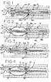
- FIG. 2is a side cross-sectional view of the delivery system of FIG. 1 , showing the stent fully deployed;
- FIG. 3is a side cross-sectional view of a delivery system for a self-expanding stent, showing the stent partially deployed;
- FIG. 4is a side cross-sectional view of the delivery system of FIG. 3 , showing the stent fully deployed;
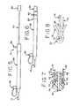
- FIG. 5is a side elevational view of the proximal end of a delivery system, showing the delivery system in an undeployed state;
- FIG. 6is a side elevational view of the proximal end of the delivery system of FIG. 5 , showing the delivery system in a deployed state;
- FIG. 7is a close-up view of a wire attached to a self-expanding stent.
- FIG. 8is a close-up view of another wire attached to a self-expanding stent.
- FIGS. 1 and 2an improved delivery system for a self-expanding stent is shown.
- the self-expanding stent 10is initially mounted within a retention sheath 14 on an inner catheter 12 .
- Various designs known in the artmay be used for the self-expanding stent 10 .
- the self-expanding stent 10may be made with serpentine rings interconnected with longitudinal struts.
- the stent 10may also be made from a braided framework of wire filaments. Other well-known stent structures are also possible.
- Various materialsmay also be used for the self-expanding stent 10 , such as nitinol and stainless steel.
- the inner catheter 12includes a stop 20 located adjacent the proximal end 22 of the stent 10 .
- the stent 10may be released from the delivery system by withdrawing the retention sheath 14 proximally relative to the inner catheter 12 .
- the stent 10typically presses outward against the retention sheath 14 , thereby producing a small amount of friction between the stent 10 and the retention sheath 14 .
- a stop 20 attached to the inner catheter 12prevents the stent 10 from moving proximally with the retention sheath 14 as the sheath 14 is withdrawn. In effect, the stent 10 is pushed out of the retention sheath 14 by the stop 20 as the retention sheath 14 is withdrawn.
- FIGS. 5 and 6A control device 24 which may be used to deploy the stent 10 is shown in FIGS. 5 and 6 .
- FIG. 5shows the control device 24 in an initial configuration before the stent 10 is deployed.
- FIG. 6shows the control device 24 in a final configuration after the stent 10 is deployed.
- the control device 24is located outside of the patient's body and is operated by the physician to control the deployment of the stent 10 at a desired treatment site within the patient's body.
- the control device 24may include a proximal control knob 26 .
- the control device 24may also include a control handle 28 located distal from the control knob 26 .
- the control knob 26may be attached to a shaft 30 that extends through the control handle 28 .
- the shaft 30is attached to the inner catheter 12 shown in FIGS. 1-4 and 7 .
- the control handle 28is attached to the retention sheath 14 .
- a guide wire lumen 32may pass through the shaft 30 and the control knob 26 as shown in FIGS. 1-4 .
- a guide wire 34may pass through the inner catheter 12 , the control device 24 and out the proximal end of the control knob 26 .
- a port 36may also be provided on the control handle 28 to pass fluids through the delivery system to the treatment site.
- the port 36is in communication with the annular space between the inner catheter 12 and the retention sheath 14 .
- a fluidmay be pumped through the space between the inner catheter 12 and the retention sheath 14 .
- the fluidmay exit from the delivery system at the distal end of the retention sheath 14 .
- the port 36may be useful in pumping contrast solution to the treatment site. Contrast solution is useful in angiography procedures to visualize an internal organ before, during or after deployment of the stent 10 .
- a locking tab 38may also be provided.
- the locking tab 38is installed in a slot 40 in the control handle 28 when the control device 24 is in the initial configuration before a stent 10 is released.
- the locking tab 38locks the control handle 28 to the shaft 30 to prevent relative movement between the control handle 28 and the control knob 26 .
- the locking tab 38prevents premature deployment or partial deployment of the stent 10 .
- the locking tab 38is removed from the control handle 28 . This unlocks the control device 24 so that the control handle 28 and control knob 26 may be moved relative to each other.
- a physicianwill release the stent 10 by pulling the control handle 28 in the proximal direction toward the control knob 26 while maintaining the control knob 26 in a fixed position.
- the retention sheath 14is withdrawn in the proximal direction. Because the proximal end 22 of the stent 10 abuts the stop 20 on the inner catheter 12 , the stent 10 does not move proximally with the retention sheath 14 . Instead, the stent 10 remains in the general position of the inner catheter 12 and expands as the retention sheath 14 is withdrawn.
- stents 10are provided with radiopaque markers or other positional locators that allow the physician to determine the location of the stent 10 while the stent 10 is within the patient's body and mounted within the delivery system.
- a physicianwill normally use these positional locators to position the stent 10 at the desired treatment site before the stent 10 is released from the delivery system.
- the stent 10may shift a small distance relative to the inner catheter 12 during release of the stent 10 . As a result, the stent 10 may not be implanted precisely where the physician desires to release the stent 10 .
- Movement of the stent 10 relative to the inner catheter 12may occur for various reasons.
- Some stents 10have a tendency to forcefully expand as soon as the distal end 46 of the stent 10 is released from the retention sheath 14 .
- expansion of the distal end 46 of the stent 10may have a tendency to draw a portion of the remaining stent 10 out of the retention sheath 14 before the stent 10 is fully released.
- the stent 10may also be subjected to a small amount of longitudinal compression as the retention sheath 14 is proximally withdrawn.
- the stent 10may be longitudinally compressed between the retention sheath 14 and the stop 20 . Upon release of the stent 10 , this compression may cause the stent 10 to pop slightly in the distal direction as the frictional forces are overcome and the compression is released.
- a stent 10may be resheathed if the stent 10 is not released at the desired treatment site. For example, if a physician determines that the position of a stent 10 should be changed, the physician may attempt to push the retention sheath 14 distally to recompress the stent 10 into the delivery system.
- this optionis of limited usefulness for several reasons. In general, resheathing of a stent 10 must be done before the stent 10 is fully released from the retention sheath 14 .
- the physicianmust make this determination when the distal end 46 of the stent 10 has been released but before the proximal end 22 of the stent 10 has been released.
- resheathing of a stent 10also only works with stents 10 that have a moderately high longitudinal stiffness. Stents 10 that are more longitudinally flexible can be more difficult to resheath.
- a wire 48may be attached to a portion of the stent 10 in order to restrain movement of the stent 10 during placement of the stent 10 within a vessel 44 .
- the wire 48may be attached to various structures or geometry of the stent 10 .
- the wire 48may be looped through eyelets 50 at the ends 22 , 46 of the stent 10 .
- the eyelets 50may be comparable to eyelets 50 that are conventionally used as radiopaque markers on stents 10 .
- the structure of the stent 10may be cut from a metallic cannula with a laser.
- An integral eyelet 50may be cut from the cannula at the same time the stent structure is formed. Typically, eyelets 50 are cut with a radial opening extending therethrough. When used as a radiopaque marker, the opening through the eyelet 50 is normally filled with a rivet made from a radiopaque material, such as gold or platinum. However, one or more of the eyelets 50 may be left open in order to loop one or more wires 48 through the eyelets 50 . If eyelets 50 are used that are comparable to radiopaque markers, some of the eyelets 50 may be used as conventional radiopaque markers and some of the eyelets 50 may be used to attach wires 48 .
- the wires 48may be attached to one portion of the stent 10 or to multiple portions of the stent 10 .
- one wire 48may be attached to either the proximal end 22 of the stent 10 , the distal end 46 of the stent 10 , or a middle portion of the stent 10 .
- Multiple wires 48may also be attached to one or more locations of the stent 10 .
- a first wire 48 ais attached to an eyelet 50 at the proximal end 22 of the stent 10
- a second wire 48 bis attached to an eyelet 50 at the distal end 46 of the stent 10 .
- the wires 48extend proximally between the retention sheath 14 and the inner catheter 12 .
- the wires 48may extend through the stop 20 by providing lumens or channels through in the stop 20 .
- the wires 48may also be embedded in the step 20 , if desired. If desired, the wires 48 may extend to the control device 24 of the delivery system and may pass out from the control device 24 to allow the physician to manually manipulate the wires 48 .
- the wires 48may be fixedly attached to the control device 24 .
- the wires 48may also be fixedly attached to the inner catheter 12 at a proximal location from the stop 20 .
- the wires 60may also be connected to the inner catheter 12 at a location distal from the stop 20 .
- the wires 60are connected to the inner catheter 12 at a location that is longitudinally aligned with the releasable attachment of the wire 60 to the stent 10 .
- the stent 10may generally be restrained in both the distal and proximal directions as the stent 10 expands from the inner catheter 12 .
- the stent 10is released substantially at the desired treatment site relative to the inner catheter 12 .
- the inner catheter 12may be pulled in the proximal direction by the physician in order to withdraw it.
- the wires 60may be releasably attached to the stent 10 .
- the wires 60release from the stent 10 and the wires 60 may be withdrawn with the inner catheter 12 .
- the middle portion of the stentmay be allowed to expand and contact the vessel wall 44 , while the proximal and distal ends 22 , 46 of the stent 10 are restrained inward away from the vessel wall 44 .
- the ends 22 , 46 of the stent 10may be restrained in several ways.
- metallic wires 48 , 60are used to restrain the ends 22 , 46 of the stent 10 in order to provide rigidity and predictability to the restraint.
- the wires 48 , 60may be made from stainless steel or nitinol.
- the wires 48 , 60 , 62may be releasably attached to the inner catheter 12 by extending a portion of the wire 62 into a region of the inner catheter 12 .
- the ends 64 of the wires 62may be embedded within a polymer region of the inner catheter 12 .
- the surface of the wire 62may be roughened to provide a higher degree of engagement between the wire 62 and the inner catheter 12 .
- the wire 62may also be provided with a structure that provides positive resistance between the wire 62 and the inner catheter 12 .
- the wire 62may be provided with a ball-like structure that is embedded within a polymer region of the inner catheter 12 .
- the wire 62may be releasably attached to the stent 10 by extending the wire 62 longitudinally through an eyelet 50 of the stent 10 . If the wire 62 extends longitudinally through the stent 10 , the wire 62 is preferably restrained tight by attaching the distal end 64 of the wire 62 to the inner catheter 12 and by restraining the proximal end 66 either by attaching the proximal end 66 to the inner catheter 12 or the control handle 28 or by manually restraining the proximal end 66 .
- the wire 68may extend through an eyelet 50 of the stent 10 and may be bent 20 around the eyelet 50 . If a psuedoelastic material is used, such as nitinol, the bend 70 may be heat set into the wire 68 to produce a memorized bend 70 in the wire 68 . Alternatively, the bend 70 may be produced by plastically deforming the wire 68 .
- the end 72 of the wire 68may be releasably attached to the inner catheter 12 as described above. However, the end 72 of the wire 68 may also be free and unconnected to the inner catheter 12 .
- the releasable attachments shown in FIGS. 7 and 8may be used as desired to restrain portions of the stent 10 to provide improved placement accuracy.
- the releasable attachment shown in FIG. 8may be particularly useful for the delivery system shown in FIGS. 3 and 4 .
- the wire 60 , 68may be fixedly attached to the inner catheter 12 , and the end 72 of the wire 60 , 68 may be unconnected to the inner catheter 12 .
- the releasable attachment shown in FIG. 7may be particularly useful for the delivery system shown in FIGS. 1 and 2 .
- the ends 64 of the wires 48 , 62may be releasably attached to the inner catheter 12 as described above.
- the wires 48 , 62may be restrained with the desired tightness by securing the proximal end 74 of the wire 62 to the inner catheter 12 or by manually restraining the proximal end 74 of the wire 62 .
- a single wire 48 , 60 , 62 , 68is used to restrain both the proximal and distal ends 22 , 46 of the stent 10
- multiple wires 48 , 60 , 62 , 68may be used around the circumference of the stent in order to restrain the full circumference of the stent 10 .
- the releasable attachment shown in FIG. 8may be used to restrain the stent 10 shown in FIGS. 1 and 2 , if desired.
- the releasable attachment shown in FIG. 7may also be used to restrain the stent 10 shown in FIGS. 3 and 4 , if desired.
Landscapes
- Health & Medical Sciences (AREA)
- Engineering & Computer Science (AREA)
- Biomedical Technology (AREA)
- Cardiology (AREA)
- Oral & Maxillofacial Surgery (AREA)
- Transplantation (AREA)
- Heart & Thoracic Surgery (AREA)
- Vascular Medicine (AREA)
- Life Sciences & Earth Sciences (AREA)
- Animal Behavior & Ethology (AREA)
- General Health & Medical Sciences (AREA)
- Public Health (AREA)
- Veterinary Medicine (AREA)
- Media Introduction/Drainage Providing Device (AREA)
Abstract
Description
- a retention sheath comprising an outer diameter and an inner lumen extending therethrough, said inner lumen forming an opening at a distal end of said retention sheath;
- an inner catheter comprising a stop extending radially outward from a portion of said inner catheter, wherein said inner catheter is disposed within said inner lumen of said retention sheath;
- a self-expanding stent disposed between said inner catheter and said retention sheath, said retention sheath thereby restraining said self-expanding stent in a collapsed configuration, wherein a proximal end of said stent is disposed adjacent said stop; and
- a metal wire releasably attached to a distal end of said stent and adapted to restrain said distal end of said stent inward toward said inner catheter when said retention sheath is withdrawn thereby preventing said distal end from contacting a vessel wall, a middle portion of said stent being unrestrained and allowed to contact said vessel wall, wherein said metal wire is releasable from said stent after said stent self-expands to allow said distal end to contact said vessel wall.
- a retention sheath comprising an outer diameter and an inner lumen extending therethrough, said inner lumen forming an opening at a distal end of said retention sheath;
- an inner catheter comprising a stop extending radially outward from a portion of said inner catheter, wherein said inner catheter is disposed within said inner lumen of said retention sheath;
- a self-expanding stent disposed between said inner catheter and said retention sheath, said retention sheath thereby restraining said self-expanding stent in a collapsed configuration, wherein a proximal end of said stent is disposed adjacent said stop; and
- a wire releasably attached to said stent with a bend in said wire that bends around a portion of said stent.
- a retention sheath comprising an outer diameter and an inner lumen extending therethrough, said inner lumen forming an opening at a distal end of said retention sheath;
- an inner catheter comprising a stop extending radially outward from a portion of said inner catheter, wherein said inner catheter is disposed within said inner lumen of said retention sheath;
- a self-expanding stent disposed between said inner catheter and said retention sheath, said retention sheath thereby restraining said self-expanding stent in a collapsed configuration, wherein a proximal end of said stent is disposed adjacent said stop; and
- a wire releasably attached to said stent by embedding a distal end of said wire in a polymer region of said inner catheter, said distal end of said wire thereby being releasable from said polymer region to release said distal end of said catheter from said inner catheter, said wire extending through a portion of said stent to restrain said stent inward.
Claims (15)
Priority Applications (1)
| Application Number | Priority Date | Filing Date | Title |
|---|---|---|---|
| US12/179,079US8092510B2 (en) | 2007-07-25 | 2008-07-24 | Retention wire for self-expanding stent |
Applications Claiming Priority (2)
| Application Number | Priority Date | Filing Date | Title |
|---|---|---|---|
| US95177907P | 2007-07-25 | 2007-07-25 | |
| US12/179,079US8092510B2 (en) | 2007-07-25 | 2008-07-24 | Retention wire for self-expanding stent |
Publications (2)
| Publication Number | Publication Date |
|---|---|
| US20090030497A1 US20090030497A1 (en) | 2009-01-29 |
| US8092510B2true US8092510B2 (en) | 2012-01-10 |
Family
ID=40296067
Family Applications (1)
| Application Number | Title | Priority Date | Filing Date |
|---|---|---|---|
| US12/179,079Expired - Fee RelatedUS8092510B2 (en) | 2007-07-25 | 2008-07-24 | Retention wire for self-expanding stent |
Country Status (1)
| Country | Link |
|---|---|
| US (1) | US8092510B2 (en) |
Cited By (15)
| Publication number | Priority date | Publication date | Assignee | Title |
|---|---|---|---|---|
| US20120215152A1 (en)* | 2002-12-02 | 2012-08-23 | Gi Dynamics, Inc. | Bariatric sleeve |
| US8834405B2 (en) | 2003-12-09 | 2014-09-16 | Gi Dynamics, Inc. | Intestinal sleeve |
| US8870806B2 (en) | 2002-12-02 | 2014-10-28 | Gi Dynamics, Inc. | Methods of treatment using a bariatric sleeve |
| US8882698B2 (en) | 2002-12-02 | 2014-11-11 | Gi Dynamics, Inc. | Anti-obesity devices |
| US20150335426A1 (en)* | 2012-12-27 | 2015-11-26 | Transcatheter Technologies Gmbh | Apparatus and set for folding or unfolding a medical implant comprising a clamping mechanism, implant and method |
| US9827124B2 (en)* | 2014-12-05 | 2017-11-28 | Cook Medical Technologies Llc | Magnetic handle assembly for prosthesis delivery device |
| US10292851B2 (en) | 2016-09-30 | 2019-05-21 | DePuy Synthes Products, Inc. | Self-expanding device delivery apparatus with dual function bump |
| US10561509B2 (en) | 2013-03-13 | 2020-02-18 | DePuy Synthes Products, Inc. | Braided stent with expansion ring and method of delivery |
| US10603157B2 (en) | 2013-03-13 | 2020-03-31 | DePuy Synthes Products, Inc. | Braid implant delivery and retraction device with distal engagement |
| US10821008B2 (en) | 2016-08-25 | 2020-11-03 | DePuy Synthes Products, Inc. | Expansion ring for a braided stent |
| US10821010B2 (en) | 2014-08-27 | 2020-11-03 | DePuy Synthes Products, Inc. | Method of making a multi-strand implant with enhanced radiopacity |
| US10893963B2 (en) | 2018-08-06 | 2021-01-19 | DePuy Synthes Products, Inc. | Stent delivery with expansion assisting delivery wire |
| US11039944B2 (en) | 2018-12-27 | 2021-06-22 | DePuy Synthes Products, Inc. | Braided stent system with one or more expansion rings |
| US11090175B2 (en) | 2018-07-30 | 2021-08-17 | DePuy Synthes Products, Inc. | Systems and methods of manufacturing and using an expansion ring |
| US11357648B2 (en) | 2018-08-06 | 2022-06-14 | DePuy Synthes Products, Inc. | Systems and methods of using a braided implant |
Families Citing this family (75)
| Publication number | Priority date | Publication date | Assignee | Title |
|---|---|---|---|---|
| CA2758946C (en) | 2004-05-25 | 2014-10-21 | Tyco Healthcare Group Lp | Vascular stenting for aneurysms |
| US20060206200A1 (en)* | 2004-05-25 | 2006-09-14 | Chestnut Medical Technologies, Inc. | Flexible vascular occluding device |
| US8267985B2 (en) | 2005-05-25 | 2012-09-18 | Tyco Healthcare Group Lp | System and method for delivering and deploying an occluding device within a vessel |
| US8617234B2 (en)* | 2004-05-25 | 2013-12-31 | Covidien Lp | Flexible vascular occluding device |
| CA2565106C (en) | 2004-05-25 | 2013-11-05 | Chestnut Medical Technologies, Inc. | Flexible vascular occluding device |
| US8623067B2 (en) | 2004-05-25 | 2014-01-07 | Covidien Lp | Methods and apparatus for luminal stenting |
| AU2005332044B2 (en) | 2005-05-25 | 2012-01-19 | Covidien Lp | System and method for delivering and deploying and occluding device within a vessel |
| US8273101B2 (en) | 2005-05-25 | 2012-09-25 | Tyco Healthcare Group Lp | System and method for delivering and deploying an occluding device within a vessel |
| US8152833B2 (en) | 2006-02-22 | 2012-04-10 | Tyco Healthcare Group Lp | Embolic protection systems having radiopaque filter mesh |
| US9149379B2 (en)* | 2007-07-16 | 2015-10-06 | Cook Medical Technologies Llc | Delivery device |
| US8163007B2 (en) | 2008-02-08 | 2012-04-24 | Cook Medical Technologies Llc | Stent designs for use with one or more trigger wires |
| US10813779B2 (en) | 2008-04-25 | 2020-10-27 | CARDINAL HEALTH SWITZERLAND 515 GmbH | Stent attachment and deployment mechanism |
| WO2009140437A1 (en) | 2008-05-13 | 2009-11-19 | Nfocus Neuromedical, Inc. | Braid implant delivery systems |
| EP2349124B1 (en)* | 2008-09-05 | 2018-10-17 | Cook Medical Technologies LLC | Apparatus for improved stent deployment |
| GB2464977B (en) | 2008-10-31 | 2010-11-03 | William Cook Europe As | Introducer for deploying a stent graft in a curved lumen and stent graft therefor |
| US11376114B2 (en) | 2008-10-31 | 2022-07-05 | Cook Medical Technologies Llc | Introducer for deploying a stent graft in a curved lumen and stent graft therefor |
| EP2391309B1 (en)* | 2008-12-30 | 2018-04-04 | Cook Medical Technologies LLC | Delivery device |
| US8771333B2 (en)* | 2009-06-23 | 2014-07-08 | Cordis Corporation | Stent-graft securement device |
| CA3009244C (en) | 2009-06-23 | 2020-04-28 | Endospan Ltd. | Vascular prostheses for treating aneurysms |
| CN102740807B (en) | 2009-11-30 | 2015-11-25 | 恩多斯潘有限公司 | Multi-component stent-graft system for implantation into vessels with multiple branches |
| EP2509535B1 (en) | 2009-12-08 | 2016-12-07 | Endospan Ltd | Endovascular stent-graft system with fenestrated and crossing stent-grafts |
| JP5901538B2 (en)* | 2010-01-29 | 2016-04-13 | クック・メディカル・テクノロジーズ・リミテッド・ライアビリティ・カンパニーCook Medical Technologies Llc | Stent feeding device |
| US20110208289A1 (en)* | 2010-02-25 | 2011-08-25 | Endospan Ltd. | Flexible Stent-Grafts |
| CA2799188A1 (en)* | 2010-05-11 | 2011-11-17 | Cook Medical Technologies Llc | Biliary access sheath |
| US8523932B2 (en) | 2010-05-24 | 2013-09-03 | Cook Medical Technologies Llc | Variable diameter trigger wire |
| EP2588042A4 (en) | 2010-06-29 | 2015-03-18 | Artventive Medical Group Inc | Reducing flow through a tubular structure |
| US9247942B2 (en) | 2010-06-29 | 2016-02-02 | Artventive Medical Group, Inc. | Reversible tubal contraceptive device |
| US9149277B2 (en) | 2010-10-18 | 2015-10-06 | Artventive Medical Group, Inc. | Expandable device delivery |
| CA2826022A1 (en) | 2011-02-03 | 2012-08-09 | Endospan Ltd. | Implantable medical devices constructed of shape memory material |
| GB201109305D0 (en)* | 2011-06-03 | 2011-07-20 | Vascutek Ltd | Method and apparatus for controlling the deployment of a stent |
| US8920482B2 (en) | 2011-06-30 | 2014-12-30 | Cook Medical Technologies Llc | Stent delivery system |
| US9254209B2 (en) | 2011-07-07 | 2016-02-09 | Endospan Ltd. | Stent fixation with reduced plastic deformation |
| US9668859B2 (en) | 2011-08-05 | 2017-06-06 | California Institute Of Technology | Percutaneous heart valve delivery systems |
| EP2739247B1 (en)* | 2011-08-05 | 2018-10-10 | California Institute of Technology | Percutaneous heart valve delivery systems |
| US9839510B2 (en) | 2011-08-28 | 2017-12-12 | Endospan Ltd. | Stent-grafts with post-deployment variable radial displacement |
| US9427339B2 (en) | 2011-10-30 | 2016-08-30 | Endospan Ltd. | Triple-collar stent-graft |
| US9597204B2 (en) | 2011-12-04 | 2017-03-21 | Endospan Ltd. | Branched stent-graft system |
| CN104363861B (en)* | 2012-04-12 | 2016-11-23 | 加州理工学院 | The cardiac valve delivery system of percutaneous |
| WO2013171730A1 (en) | 2012-05-15 | 2013-11-21 | Endospan Ltd. | Stent-graft with fixation elements that are radially confined for delivery |
| US9173756B2 (en) | 2012-06-13 | 2015-11-03 | Cook Medical Technologies Llc | Systems and methods for deploying a portion of a stent using at least one coiled member |
| US9144510B2 (en) | 2012-06-13 | 2015-09-29 | Cook Medical Technologies Llc | Systems and methods for deploying a portion of a stent using at least one coiled member |
| US9155647B2 (en) | 2012-07-18 | 2015-10-13 | Covidien Lp | Methods and apparatus for luminal stenting |
| US9301831B2 (en) | 2012-10-30 | 2016-04-05 | Covidien Lp | Methods for attaining a predetermined porosity of a vascular device |
| US9452070B2 (en) | 2012-10-31 | 2016-09-27 | Covidien Lp | Methods and systems for increasing a density of a region of a vascular device |
| US9750626B2 (en)* | 2012-10-31 | 2017-09-05 | Cook Medical Technologies Llc | Apparatus and methods for improved stent deployment |
| US9943427B2 (en) | 2012-11-06 | 2018-04-17 | Covidien Lp | Shaped occluding devices and methods of using the same |
| US9622893B2 (en) | 2012-12-20 | 2017-04-18 | Cook Medical Technologies Llc | Apparatus and method for improved deployment of endovascular grafts |
| US9687373B2 (en) | 2012-12-21 | 2017-06-27 | Cook Medical Technologies Llc | Systems and methods for securing and releasing a portion of a stent |
| US9655756B2 (en) | 2012-12-21 | 2017-05-23 | Cook Medical Technologies Llc | Systems and methods for deploying a portion of a stent using an auger-style device |
| US9993360B2 (en) | 2013-01-08 | 2018-06-12 | Endospan Ltd. | Minimization of stent-graft migration during implantation |
| US9157174B2 (en) | 2013-02-05 | 2015-10-13 | Covidien Lp | Vascular device for aneurysm treatment and providing blood flow into a perforator vessel |
| US8984733B2 (en) | 2013-02-05 | 2015-03-24 | Artventive Medical Group, Inc. | Bodily lumen occlusion |
| US9095344B2 (en) | 2013-02-05 | 2015-08-04 | Artventive Medical Group, Inc. | Methods and apparatuses for blood vessel occlusion |
| US11331208B2 (en)* | 2013-03-05 | 2022-05-17 | Cook Medical Technologies Llc | Inner catheter with a pusher band |
| US9668892B2 (en) | 2013-03-11 | 2017-06-06 | Endospan Ltd. | Multi-component stent-graft system for aortic dissections |
| US9308108B2 (en) | 2013-03-13 | 2016-04-12 | Cook Medical Technologies Llc | Controlled release and recapture stent-deployment device |
| US9855160B2 (en)* | 2013-03-14 | 2018-01-02 | W. L. Gore & Associates, Inc. | Endoprosthesis delivery systems with deployment aids |
| WO2014144247A1 (en) | 2013-03-15 | 2014-09-18 | Arash Kheradvar | Handle mechanism and functionality for repositioning and retrieval of transcatheter heart valves |
| US9248037B2 (en)* | 2013-03-15 | 2016-02-02 | Cook Medical Technologies Llc | Automatic wireless medical device release mechanism |
| US11076952B2 (en) | 2013-06-14 | 2021-08-03 | The Regents Of The University Of California | Collapsible atrioventricular valve prosthesis |
| US9968445B2 (en) | 2013-06-14 | 2018-05-15 | The Regents Of The University Of California | Transcatheter mitral valve |
| US9737308B2 (en) | 2013-06-14 | 2017-08-22 | Artventive Medical Group, Inc. | Catheter-assisted tumor treatment |
| US10149968B2 (en) | 2013-06-14 | 2018-12-11 | Artventive Medical Group, Inc. | Catheter-assisted tumor treatment |
| US9636116B2 (en) | 2013-06-14 | 2017-05-02 | Artventive Medical Group, Inc. | Implantable luminal devices |
| US9737306B2 (en) | 2013-06-14 | 2017-08-22 | Artventive Medical Group, Inc. | Implantable luminal devices |
| WO2015075708A1 (en)* | 2013-11-19 | 2015-05-28 | Endospan Ltd. | Stent system with radial-expansion locking |
| US10363043B2 (en) | 2014-05-01 | 2019-07-30 | Artventive Medical Group, Inc. | Treatment of incompetent vessels |
| CN106029005B (en) | 2014-12-18 | 2018-01-19 | 恩都思潘有限公司 | The Endovascular stent-graft of horizontal conduit with tired resistance |
| JP6854282B2 (en)* | 2015-09-18 | 2021-04-07 | テルモ株式会社 | Pressable implant delivery system |
| US10813644B2 (en) | 2016-04-01 | 2020-10-27 | Artventive Medical Group, Inc. | Occlusive implant and delivery system |
| US10709541B2 (en) | 2017-04-28 | 2020-07-14 | Cook Medical Technologies Llc | Systems and methods for adjusting the diameter of an endoluminal prosthesis and an endoluminal prosthesis configured for the same |
| JP7214739B2 (en)* | 2018-08-13 | 2023-01-30 | オリンパス株式会社 | Stent delivery device and stent delivery system |
| FR3106489A1 (en)* | 2020-01-23 | 2021-07-30 | Cormove | Device for treating a blood vessel |
| GB2605559B (en) | 2021-01-07 | 2023-04-05 | Cook Medical Technologies Llc | Stent graft |
| CN118649011B (en)* | 2024-08-16 | 2025-04-15 | 普利瑞医疗科技(苏州)有限公司 | A vascular stent system |
Citations (49)
| Publication number | Priority date | Publication date | Assignee | Title |
|---|---|---|---|---|
| US5019085A (en)* | 1988-10-25 | 1991-05-28 | Cordis Corporation | Apparatus and method for placement of a stent within a subject vessel |
| US5035706A (en) | 1989-10-17 | 1991-07-30 | Cook Incorporated | Percutaneous stent and method for retrieval thereof |
| US5290305A (en) | 1991-10-11 | 1994-03-01 | Kanji Inoue | Appliance collapsible for insertion into human organs and capable of resilient restoration |
| US5405378A (en)* | 1992-05-20 | 1995-04-11 | Strecker; Ernst P. | Device with a prosthesis implantable in the body of a patient |
| US5713948A (en) | 1995-07-19 | 1998-02-03 | Uflacker; Renan | Adjustable and retrievable graft and graft delivery system for stent-graft system |
| US5779732A (en)* | 1997-03-31 | 1998-07-14 | Medtronic, Inc. | Method and apparatus for implanting a film with an exandable stent |
| US5782838A (en)* | 1994-10-20 | 1998-07-21 | Medtronic Instent, Inc. | Cytoscope delivery system |
| US5800521A (en) | 1994-11-09 | 1998-09-01 | Endotex Interventional Systems, Inc. | Prosthetic graft and method for aneurysm repair |
| US5843158A (en)* | 1996-01-05 | 1998-12-01 | Medtronic, Inc. | Limited expansion endoluminal prostheses and methods for their use |
| US5873907A (en)* | 1998-01-27 | 1999-02-23 | Endotex Interventional Systems, Inc. | Electrolytic stent delivery system and methods of use |
| US5925076A (en) | 1995-05-19 | 1999-07-20 | Inoue; Kanji | Appliance to be implanted, method of collapsing the appliance to be implanted and method of using the appliance to be implanted |
| US6102918A (en) | 1998-02-18 | 2000-08-15 | Montefiore Hospital And Medical Center | Collapsible low-profile vascular graft implantation instrument and method for use thereof |
| US6270504B1 (en)* | 1996-08-23 | 2001-08-07 | Scimed Life Systems, Inc. | Stent delivery system |
| US6319287B1 (en) | 1999-04-09 | 2001-11-20 | B. Braun Melsungen Ag | Stent assembly |
| US6371979B1 (en)* | 1993-01-27 | 2002-04-16 | Intratherapeutics, Inc. | Stent delivery system |
| US6413269B1 (en) | 2000-07-06 | 2002-07-02 | Endocare, Inc. | Stent delivery system |
| US20020091439A1 (en)* | 1994-12-15 | 2002-07-11 | Baker Steve G. | Graft assembly having support structure |
| US6425898B1 (en)* | 1998-03-13 | 2002-07-30 | Cordis Corporation | Delivery apparatus for a self-expanding stent |
| US20020143387A1 (en) | 2001-03-27 | 2002-10-03 | Soetikno Roy M. | Stent repositioning and removal |
| US20020188341A1 (en)* | 2001-05-10 | 2002-12-12 | Elliott Christopher J. | Stent with detachable tethers and method of using same |
| US6537284B1 (en) | 1998-10-29 | 2003-03-25 | Kanji Inoue | Device for guiding an appliance |
| US6562064B1 (en)* | 2000-10-27 | 2003-05-13 | Vascular Architects, Inc. | Placement catheter assembly |
| US20030114916A1 (en)* | 1993-03-11 | 2003-06-19 | Gregory Pinchasik | Stent |
| US6607539B1 (en)* | 2001-05-18 | 2003-08-19 | Endovascular Technologies, Inc. | Electric endovascular implant depolyment system |
| US20030233140A1 (en)* | 2002-05-29 | 2003-12-18 | William A. Cook Australia Pty Ltd | Trigger wire system |
| US20040073289A1 (en)* | 2002-08-23 | 2004-04-15 | William A. Cook Australia Pty. Ltd. | Asymmetric stent graft attachment |
| US6733521B2 (en)* | 2001-04-11 | 2004-05-11 | Trivascular, Inc. | Delivery system and method for endovascular graft |
| US6740111B1 (en)* | 1996-06-20 | 2004-05-25 | Vascutek Limited | Device for retaining a prosthesis within a body passage |
| US6761733B2 (en)* | 2001-04-11 | 2004-07-13 | Trivascular, Inc. | Delivery system and method for bifurcated endovascular graft |
| US6776791B1 (en)* | 1998-04-01 | 2004-08-17 | Endovascular Technologies, Inc. | Stent and method and device for packing of same |
| US20040193178A1 (en)* | 2003-03-26 | 2004-09-30 | Cardiomind, Inc. | Multiple joint implant delivery systems for sequentially-controlled implant deployment |
| US6821291B2 (en) | 2001-06-01 | 2004-11-23 | Ams Research Corporation | Retrievable stent and method of use thereof |
| US6855159B1 (en) | 1999-02-05 | 2005-02-15 | Eva Corporation | Surgical guide line assembly and separator assembly for use during a surgical procedure |
| US20050049670A1 (en)* | 2003-08-29 | 2005-03-03 | Jones Donald K. | Self-expanding stent and stent delivery system for treatment of vascular disease |
| US20050060018A1 (en)* | 2003-09-16 | 2005-03-17 | Cook Incorporated | Prosthesis deployment system |
| US20050085890A1 (en)* | 2003-10-15 | 2005-04-21 | Cook Incorporated | Prosthesis deployment system retention device |
| US20050107862A1 (en) | 2003-10-10 | 2005-05-19 | William Cook Europe Aps | Stent graft retention system |
| US20050119722A1 (en)* | 2003-09-12 | 2005-06-02 | Mikolaj Styrc | Device for treating a blood vessel and a method of preparing the device |
| US20050125051A1 (en)* | 2003-12-05 | 2005-06-09 | Scimed Life Systems, Inc. | Detachable segment stent |
| US20060004433A1 (en) | 2004-06-16 | 2006-01-05 | Cook Incorporated | Thoracic deployment device and stent graft |
| US7022132B2 (en)* | 1999-01-15 | 2006-04-04 | Boston Scientific Scimed, Inc. | Stents with temporary retaining bands |
| US20060136035A1 (en)* | 2004-12-20 | 2006-06-22 | Vascular Architects, Inc. A Delaware Corporation | Coiled endoluminal prosthesis system and delivery catheter |
| US20060142836A1 (en)* | 2004-09-28 | 2006-06-29 | William A. Cook Australia Pty. Ltd. | Device for treating aortic dissection |
| US20080114435A1 (en)* | 2006-03-07 | 2008-05-15 | Med Institute, Inc. | Flexible delivery system |
| US7435253B1 (en)* | 1997-05-26 | 2008-10-14 | William A. Cook Australia Pty Ltd | Prosthesis and a method and means of deploying a prosthesis |
| US20090048656A1 (en)* | 2005-11-09 | 2009-02-19 | Ning Wen | Delivery Device for Delivering a Self-Expanding Stent |
| US7651521B2 (en)* | 2004-03-02 | 2010-01-26 | Cardiomind, Inc. | Corewire actuated delivery system with fixed distal stent-carrying extension |
| US7785361B2 (en)* | 2003-03-26 | 2010-08-31 | Julian Nikolchev | Implant delivery technologies |
| US7862602B2 (en)* | 2005-11-02 | 2011-01-04 | Biosensors International Group, Ltd | Indirect-release electrolytic implant delivery systems |
Family Cites Families (1)
| Publication number | Priority date | Publication date | Assignee | Title |
|---|---|---|---|---|
| US6855158B2 (en)* | 2001-09-11 | 2005-02-15 | Hill-Rom Services, Inc. | Thermo-regulating patient support structure |
- 2008
- 2008-07-24USUS12/179,079patent/US8092510B2/ennot_activeExpired - Fee Related
Patent Citations (54)
| Publication number | Priority date | Publication date | Assignee | Title |
|---|---|---|---|---|
| US5019085A (en)* | 1988-10-25 | 1991-05-28 | Cordis Corporation | Apparatus and method for placement of a stent within a subject vessel |
| US5035706A (en) | 1989-10-17 | 1991-07-30 | Cook Incorporated | Percutaneous stent and method for retrieval thereof |
| US5290305A (en) | 1991-10-11 | 1994-03-01 | Kanji Inoue | Appliance collapsible for insertion into human organs and capable of resilient restoration |
| US5405378A (en)* | 1992-05-20 | 1995-04-11 | Strecker; Ernst P. | Device with a prosthesis implantable in the body of a patient |
| US6371979B1 (en)* | 1993-01-27 | 2002-04-16 | Intratherapeutics, Inc. | Stent delivery system |
| US20030114916A1 (en)* | 1993-03-11 | 2003-06-19 | Gregory Pinchasik | Stent |
| US6666881B1 (en)* | 1993-03-11 | 2003-12-23 | Medinol Ltd. | Method of heating a nitinol stent |
| US5782838A (en)* | 1994-10-20 | 1998-07-21 | Medtronic Instent, Inc. | Cytoscope delivery system |
| US5800521A (en) | 1994-11-09 | 1998-09-01 | Endotex Interventional Systems, Inc. | Prosthetic graft and method for aneurysm repair |
| US20020091439A1 (en)* | 1994-12-15 | 2002-07-11 | Baker Steve G. | Graft assembly having support structure |
| US5925076A (en) | 1995-05-19 | 1999-07-20 | Inoue; Kanji | Appliance to be implanted, method of collapsing the appliance to be implanted and method of using the appliance to be implanted |
| US6254629B1 (en)* | 1995-05-19 | 2001-07-03 | Kanji Inoue | Appliance to be implanted, method of collapsing the appliance to be implanted and method of using the appliance to be implanted |
| US5713948A (en) | 1995-07-19 | 1998-02-03 | Uflacker; Renan | Adjustable and retrievable graft and graft delivery system for stent-graft system |
| US5843158A (en)* | 1996-01-05 | 1998-12-01 | Medtronic, Inc. | Limited expansion endoluminal prostheses and methods for their use |
| US6740111B1 (en)* | 1996-06-20 | 2004-05-25 | Vascutek Limited | Device for retaining a prosthesis within a body passage |
| US6270504B1 (en)* | 1996-08-23 | 2001-08-07 | Scimed Life Systems, Inc. | Stent delivery system |
| US5779732A (en)* | 1997-03-31 | 1998-07-14 | Medtronic, Inc. | Method and apparatus for implanting a film with an exandable stent |
| US7435253B1 (en)* | 1997-05-26 | 2008-10-14 | William A. Cook Australia Pty Ltd | Prosthesis and a method and means of deploying a prosthesis |
| US6168618B1 (en)* | 1998-01-27 | 2001-01-02 | Endotex Interventional Systems, Inc. | Electrolytic stent delivery system and methods of use |
| US5873907A (en)* | 1998-01-27 | 1999-02-23 | Endotex Interventional Systems, Inc. | Electrolytic stent delivery system and methods of use |
| US6102918A (en) | 1998-02-18 | 2000-08-15 | Montefiore Hospital And Medical Center | Collapsible low-profile vascular graft implantation instrument and method for use thereof |
| US6425898B1 (en)* | 1998-03-13 | 2002-07-30 | Cordis Corporation | Delivery apparatus for a self-expanding stent |
| US6776791B1 (en)* | 1998-04-01 | 2004-08-17 | Endovascular Technologies, Inc. | Stent and method and device for packing of same |
| US6537284B1 (en) | 1998-10-29 | 2003-03-25 | Kanji Inoue | Device for guiding an appliance |
| US7022132B2 (en)* | 1999-01-15 | 2006-04-04 | Boston Scientific Scimed, Inc. | Stents with temporary retaining bands |
| US6855159B1 (en) | 1999-02-05 | 2005-02-15 | Eva Corporation | Surgical guide line assembly and separator assembly for use during a surgical procedure |
| US6319287B1 (en) | 1999-04-09 | 2001-11-20 | B. Braun Melsungen Ag | Stent assembly |
| US6413269B1 (en) | 2000-07-06 | 2002-07-02 | Endocare, Inc. | Stent delivery system |
| US6562064B1 (en)* | 2000-10-27 | 2003-05-13 | Vascular Architects, Inc. | Placement catheter assembly |
| US20020143387A1 (en) | 2001-03-27 | 2002-10-03 | Soetikno Roy M. | Stent repositioning and removal |
| US6733521B2 (en)* | 2001-04-11 | 2004-05-11 | Trivascular, Inc. | Delivery system and method for endovascular graft |
| US6761733B2 (en)* | 2001-04-11 | 2004-07-13 | Trivascular, Inc. | Delivery system and method for bifurcated endovascular graft |
| US20020188341A1 (en)* | 2001-05-10 | 2002-12-12 | Elliott Christopher J. | Stent with detachable tethers and method of using same |
| US6607539B1 (en)* | 2001-05-18 | 2003-08-19 | Endovascular Technologies, Inc. | Electric endovascular implant depolyment system |
| US6821291B2 (en) | 2001-06-01 | 2004-11-23 | Ams Research Corporation | Retrievable stent and method of use thereof |
| US20030233140A1 (en)* | 2002-05-29 | 2003-12-18 | William A. Cook Australia Pty Ltd | Trigger wire system |
| US7803177B2 (en)* | 2002-05-29 | 2010-09-28 | Cook Incorporated | Trigger wire system |
| US20040073289A1 (en)* | 2002-08-23 | 2004-04-15 | William A. Cook Australia Pty. Ltd. | Asymmetric stent graft attachment |
| US20040193178A1 (en)* | 2003-03-26 | 2004-09-30 | Cardiomind, Inc. | Multiple joint implant delivery systems for sequentially-controlled implant deployment |
| US7785361B2 (en)* | 2003-03-26 | 2010-08-31 | Julian Nikolchev | Implant delivery technologies |
| US20050049670A1 (en)* | 2003-08-29 | 2005-03-03 | Jones Donald K. | Self-expanding stent and stent delivery system for treatment of vascular disease |
| US20050119722A1 (en)* | 2003-09-12 | 2005-06-02 | Mikolaj Styrc | Device for treating a blood vessel and a method of preparing the device |
| US20050060018A1 (en)* | 2003-09-16 | 2005-03-17 | Cook Incorporated | Prosthesis deployment system |
| US7335224B2 (en)* | 2003-10-10 | 2008-02-26 | William Cook Europe Aps | Stent graft retention system |
| US20050107862A1 (en) | 2003-10-10 | 2005-05-19 | William Cook Europe Aps | Stent graft retention system |
| US20050085890A1 (en)* | 2003-10-15 | 2005-04-21 | Cook Incorporated | Prosthesis deployment system retention device |
| US20050125051A1 (en)* | 2003-12-05 | 2005-06-09 | Scimed Life Systems, Inc. | Detachable segment stent |
| US7651521B2 (en)* | 2004-03-02 | 2010-01-26 | Cardiomind, Inc. | Corewire actuated delivery system with fixed distal stent-carrying extension |
| US20060004433A1 (en) | 2004-06-16 | 2006-01-05 | Cook Incorporated | Thoracic deployment device and stent graft |
| US20060142836A1 (en)* | 2004-09-28 | 2006-06-29 | William A. Cook Australia Pty. Ltd. | Device for treating aortic dissection |
| US20060136035A1 (en)* | 2004-12-20 | 2006-06-22 | Vascular Architects, Inc. A Delaware Corporation | Coiled endoluminal prosthesis system and delivery catheter |
| US7862602B2 (en)* | 2005-11-02 | 2011-01-04 | Biosensors International Group, Ltd | Indirect-release electrolytic implant delivery systems |
| US20090048656A1 (en)* | 2005-11-09 | 2009-02-19 | Ning Wen | Delivery Device for Delivering a Self-Expanding Stent |
| US20080114435A1 (en)* | 2006-03-07 | 2008-05-15 | Med Institute, Inc. | Flexible delivery system |
Cited By (30)
| Publication number | Priority date | Publication date | Assignee | Title |
|---|---|---|---|---|
| US20120215152A1 (en)* | 2002-12-02 | 2012-08-23 | Gi Dynamics, Inc. | Bariatric sleeve |
| US9901474B2 (en) | 2002-12-02 | 2018-02-27 | Gi Dynamics, Inc. | Anti-obesity devices |
| US8870806B2 (en) | 2002-12-02 | 2014-10-28 | Gi Dynamics, Inc. | Methods of treatment using a bariatric sleeve |
| US8882698B2 (en) | 2002-12-02 | 2014-11-11 | Gi Dynamics, Inc. | Anti-obesity devices |
| US9750596B2 (en) | 2002-12-02 | 2017-09-05 | Gi Dynamics, Inc. | Bariatric sleeve |
| US9155609B2 (en)* | 2002-12-02 | 2015-10-13 | Gi Dynamics, Inc. | Bariatric sleeve |
| US9278020B2 (en) | 2002-12-02 | 2016-03-08 | Gi Dynamics, Inc. | Methods of treatment using a bariatric sleeve |
| US9237944B2 (en) | 2003-12-09 | 2016-01-19 | Gi Dynamics, Inc. | Intestinal sleeve |
| US9585783B2 (en) | 2003-12-09 | 2017-03-07 | Gi Dynamics, Inc. | Methods and apparatus for anchoring within the gastrointestinal tract |
| US9744061B2 (en) | 2003-12-09 | 2017-08-29 | Gi Dynamics, Inc. | Intestinal sleeve |
| US9084669B2 (en) | 2003-12-09 | 2015-07-21 | Gi Dynamics, Inc. | Methods and apparatus for anchoring within the gastrointestinal tract |
| US8834405B2 (en) | 2003-12-09 | 2014-09-16 | Gi Dynamics, Inc. | Intestinal sleeve |
| US9795479B2 (en)* | 2012-12-27 | 2017-10-24 | Venus Medtech (Hangzhou), Inc. | Apparatus and set for folding or unfolding a medical implant comprising a clamping mechanism, implant and method |
| US20150335426A1 (en)* | 2012-12-27 | 2015-11-26 | Transcatheter Technologies Gmbh | Apparatus and set for folding or unfolding a medical implant comprising a clamping mechanism, implant and method |
| US11452623B2 (en) | 2013-03-13 | 2022-09-27 | DePuy Synthes Products, Inc. | Braided stent with expansion ring and method of delivery |
| US11529249B2 (en) | 2013-03-13 | 2022-12-20 | DePuy Synthes Products, Inc. | Braided stent with expansion ring and method of delivery |
| US10561509B2 (en) | 2013-03-13 | 2020-02-18 | DePuy Synthes Products, Inc. | Braided stent with expansion ring and method of delivery |
| US10603157B2 (en) | 2013-03-13 | 2020-03-31 | DePuy Synthes Products, Inc. | Braid implant delivery and retraction device with distal engagement |
| US10821010B2 (en) | 2014-08-27 | 2020-11-03 | DePuy Synthes Products, Inc. | Method of making a multi-strand implant with enhanced radiopacity |
| US9827124B2 (en)* | 2014-12-05 | 2017-11-28 | Cook Medical Technologies Llc | Magnetic handle assembly for prosthesis delivery device |
| US10821008B2 (en) | 2016-08-25 | 2020-11-03 | DePuy Synthes Products, Inc. | Expansion ring for a braided stent |
| US11129738B2 (en) | 2016-09-30 | 2021-09-28 | DePuy Synthes Products, Inc. | Self-expanding device delivery apparatus with dual function bump |
| US10292851B2 (en) | 2016-09-30 | 2019-05-21 | DePuy Synthes Products, Inc. | Self-expanding device delivery apparatus with dual function bump |
| US12064363B2 (en) | 2016-09-30 | 2024-08-20 | DePuy Synthes Products, Inc. | Self-expanding device delivery apparatus with dual function bump |
| US11090175B2 (en) | 2018-07-30 | 2021-08-17 | DePuy Synthes Products, Inc. | Systems and methods of manufacturing and using an expansion ring |
| US11497638B2 (en) | 2018-07-30 | 2022-11-15 | DePuy Synthes Products, Inc. | Systems and methods of manufacturing and using an expansion ring |
| US11357648B2 (en) | 2018-08-06 | 2022-06-14 | DePuy Synthes Products, Inc. | Systems and methods of using a braided implant |
| US10893963B2 (en) | 2018-08-06 | 2021-01-19 | DePuy Synthes Products, Inc. | Stent delivery with expansion assisting delivery wire |
| US12004977B2 (en) | 2018-08-06 | 2024-06-11 | DePuy Synthes Products, Inc. | Systems and methods of using a braided implant |
| US11039944B2 (en) | 2018-12-27 | 2021-06-22 | DePuy Synthes Products, Inc. | Braided stent system with one or more expansion rings |
Also Published As
| Publication number | Publication date |
|---|---|
| US20090030497A1 (en) | 2009-01-29 |
Similar Documents
| Publication | Publication Date | Title |
|---|---|---|
| US8092510B2 (en) | Retention wire for self-expanding stent | |
| US8992591B2 (en) | Delivery system with low longitudinal compressibility | |
| EP2875798B1 (en) | Braided stent | |
| US12336901B2 (en) | Systems and methods for adjusting the diameter of an endoluminal prosthesis and an endoluminal prosthesis configured for the same | |
| US10517748B2 (en) | Prosthesis with guide lumen | |
| AU2010322201B2 (en) | Stent graft and introducer assembly | |
| US9700399B2 (en) | Stopper to prevent graft material slippage in a closed web stent-graft | |
| EP2537491B1 (en) | Helical stent | |
| US8419782B2 (en) | Precise positioning prosthesis delivery system and method | |
| US20110125249A1 (en) | Stent Graft and Introducer Assembly | |
| EP4205701A1 (en) | Covered stent |
Legal Events
| Date | Code | Title | Description |
|---|---|---|---|
| AS | Assignment | Owner name:MED INSTITUTE, INC., INDIANA Free format text:ASSIGNMENT OF ASSIGNORS INTEREST;ASSIGNORS:METCALF, JUSTIN M;BROWN, JASON S;REEL/FRAME:021647/0590 Effective date:20080919 | |
| AS | Assignment | Owner name:MED INSTITUTE, INC., INDIANA Free format text:CORRECTIVE ASSIGNMENT TO CORRECT THE SECOND LISTED CONVEYING PARTY JASON S. BROWN SHOULD BE CHANGED TO TO JASON S. BOWE PER EXECUTED ASSIGNMENT. PREVIOUSLY RECORDED ON REEL 021647 FRAME 0590;ASSIGNORS:METCALF, JUSTIN M;BOWE, JASON S;REEL/FRAME:021655/0725 Effective date:20080919 Owner name:MED INSTITUTE, INC., INDIANA Free format text:CORRECTIVE ASSIGNMENT TO CORRECT THE SECOND LISTED CONVEYING PARTY JASON S. BROWN SHOULD BE CHANGED TO TO JASON S. BOWE PER EXECUTED ASSIGNMENT. PREVIOUSLY RECORDED ON REEL 021647 FRAME 0590. ASSIGNOR(S) HEREBY CONFIRMS THE JASON S. BOWE;ASSIGNORS:METCALF, JUSTIN M;BOWE, JASON S;REEL/FRAME:021655/0725 Effective date:20080919 | |
| ZAAA | Notice of allowance and fees due | Free format text:ORIGINAL CODE: NOA | |
| ZAAB | Notice of allowance mailed | Free format text:ORIGINAL CODE: MN/=. | |
| AS | Assignment | Owner name:COOK MEDICAL TECHNOLOGIES LLC, INDIANA Free format text:ASSIGNMENT OF ASSIGNORS INTEREST;ASSIGNOR:MED INSTITUTE, INC.;REEL/FRAME:027326/0497 Effective date:20111202 | |
| STCF | Information on status: patent grant | Free format text:PATENTED CASE | |
| FPAY | Fee payment | Year of fee payment:4 | |
| MAFP | Maintenance fee payment | Free format text:PAYMENT OF MAINTENANCE FEE, 8TH YEAR, LARGE ENTITY (ORIGINAL EVENT CODE: M1552); ENTITY STATUS OF PATENT OWNER: LARGE ENTITY Year of fee payment:8 | |
| FEPP | Fee payment procedure | Free format text:MAINTENANCE FEE REMINDER MAILED (ORIGINAL EVENT CODE: REM.); ENTITY STATUS OF PATENT OWNER: LARGE ENTITY | |
| LAPS | Lapse for failure to pay maintenance fees | Free format text:PATENT EXPIRED FOR FAILURE TO PAY MAINTENANCE FEES (ORIGINAL EVENT CODE: EXP.); ENTITY STATUS OF PATENT OWNER: LARGE ENTITY | |
| STCH | Information on status: patent discontinuation | Free format text:PATENT EXPIRED DUE TO NONPAYMENT OF MAINTENANCE FEES UNDER 37 CFR 1.362 | |
| AS | Assignment | Owner name:WILMINGTON TRUST, NATIONAL ASSOCIATION, AS COLLATERAL AGENT, DELAWARE Free format text:SECURITY INTEREST;ASSIGNOR:COOK MEDICAL TECHNOLOGIES LLC;REEL/FRAME:066700/0277 Effective date:20240227 | |
| FP | Lapsed due to failure to pay maintenance fee | Effective date:20240110 |