US8092508B2 - Implantable medical endoprosthesis delivery system - Google Patents
Implantable medical endoprosthesis delivery systemDownload PDFInfo
- Publication number
- US8092508B2 US8092508B2US11/395,479US39547906AUS8092508B2US 8092508 B2US8092508 B2US 8092508B2US 39547906 AUS39547906 AUS 39547906AUS 8092508 B2US8092508 B2US 8092508B2
- Authority
- US
- United States
- Prior art keywords
- endoprosthesis
- delivery
- delivery member
- bumper
- seating
- Prior art date
- Legal status (The legal status is an assumption and is not a legal conclusion. Google has not performed a legal analysis and makes no representation as to the accuracy of the status listed.)
- Active, expires
Links
Images


Classifications
- A—HUMAN NECESSITIES
- A61—MEDICAL OR VETERINARY SCIENCE; HYGIENE
- A61F—FILTERS IMPLANTABLE INTO BLOOD VESSELS; PROSTHESES; DEVICES PROVIDING PATENCY TO, OR PREVENTING COLLAPSING OF, TUBULAR STRUCTURES OF THE BODY, e.g. STENTS; ORTHOPAEDIC, NURSING OR CONTRACEPTIVE DEVICES; FOMENTATION; TREATMENT OR PROTECTION OF EYES OR EARS; BANDAGES, DRESSINGS OR ABSORBENT PADS; FIRST-AID KITS
- A61F2/00—Filters implantable into blood vessels; Prostheses, i.e. artificial substitutes or replacements for parts of the body; Appliances for connecting them with the body; Devices providing patency to, or preventing collapsing of, tubular structures of the body, e.g. stents
- A61F2/95—Instruments specially adapted for placement or removal of stents or stent-grafts
- A61F2/962—Instruments specially adapted for placement or removal of stents or stent-grafts having an outer sleeve
- A61F2/966—Instruments specially adapted for placement or removal of stents or stent-grafts having an outer sleeve with relative longitudinal movement between outer sleeve and prosthesis, e.g. using a push rod
- A61F2/9661—Instruments specially adapted for placement or removal of stents or stent-grafts having an outer sleeve with relative longitudinal movement between outer sleeve and prosthesis, e.g. using a push rod the proximal portion of the stent or stent-graft is released first
- A—HUMAN NECESSITIES
- A61—MEDICAL OR VETERINARY SCIENCE; HYGIENE
- A61F—FILTERS IMPLANTABLE INTO BLOOD VESSELS; PROSTHESES; DEVICES PROVIDING PATENCY TO, OR PREVENTING COLLAPSING OF, TUBULAR STRUCTURES OF THE BODY, e.g. STENTS; ORTHOPAEDIC, NURSING OR CONTRACEPTIVE DEVICES; FOMENTATION; TREATMENT OR PROTECTION OF EYES OR EARS; BANDAGES, DRESSINGS OR ABSORBENT PADS; FIRST-AID KITS
- A61F2/00—Filters implantable into blood vessels; Prostheses, i.e. artificial substitutes or replacements for parts of the body; Appliances for connecting them with the body; Devices providing patency to, or preventing collapsing of, tubular structures of the body, e.g. stents
- A61F2/95—Instruments specially adapted for placement or removal of stents or stent-grafts
- A61F2/962—Instruments specially adapted for placement or removal of stents or stent-grafts having an outer sleeve
- A61F2/966—Instruments specially adapted for placement or removal of stents or stent-grafts having an outer sleeve with relative longitudinal movement between outer sleeve and prosthesis, e.g. using a push rod
- A61F2002/9665—Instruments specially adapted for placement or removal of stents or stent-grafts having an outer sleeve with relative longitudinal movement between outer sleeve and prosthesis, e.g. using a push rod with additional retaining means
Definitions
- This disclosuregenerally relates to implantable medical endoprosthesis delivery systems and related components, as well as related methods.
- Systemsare known for delivering medical devices, such as stents, into a body lumen.
- a proximal portiontypically includes a handle that is held by an operator of the system (e.g., a physician) during use, and the distal portion can include an outer member surrounding an inner member with a stent positioned therebetween.
- the operator of the systempositions the distal portion within the lumen at a desired location (e.g., so that the stent is adjacent an occlusion). The operator can then retract the outer member to allow the stent to engage the occlusion/lumen wall. Thereafter, the operator removes the distal portion of the system from the lumen.
- implantable medical endoprosthesis delivery systemsinclude a delivery member, a sheath, and an endoprosthesis disposed between the delivery member and the sheath.
- a second memberis included, the second member being configured so that when the sheath moves proximally or distally with respect to the delivery member, the endoprosthesis remains substantially stationary in a longitudinal direction with respect to the delivery member, and when the delivery member moves proximally or distally, the endoprosthesis remains substantially stationary with respect to the delivery member.
- implantable medical endoprosthesis delivery systemsinclude a delivery member, a sheath, an endoprosthesis disposed between the delivery member and the sheath, and a seating member disposed between the delivery member and the endoprosthesis.
- implantable medical endoprosthesis delivery systemsincluding a delivery member, a sheath, an endoprosthesis disposed between the delivery member and the sheath, and a coating supported by the delivery member and disposed between the delivery member and the endoprosthesis.
- implantable medical endoprosthesis delivery systemsincluding a delivery member, a sheath, an endoprosthesis disposed between the delivery member and the sheath, and windings of a material supported by the delivery member.
- articlesincluding a first material having a first portion, a second portion, and a third portion disposed between the first and second portions, and windings of a second material supported by the first and second portions of the first material.
- the second materialis unsupported by the third portion of the first material.
- the articlecan be, e.g., a delivery wire or a guide wire, which itself can be a delivery wire.
- implantable medical endoprosthesis delivery systemscomprise a wire that includes a first material having a first portion, a second portion, and a third portion disposed between the first and second portions, and windings of a second material supported by the first and third portions of the first material.
- the systemsfurther include a sheath and an endoprosthesis disposed between the wire and the sheath.
- methodsinclude withdrawing a sheath to at least partially uncover an endoprosthesis that was previously disposed within the sheath, thereby allowing the at least a portion of the endoprosthesis to expand, and advancing the sheath to cover at least some of the expanded portion of the endoprosthesis, thereby disposing at least some of the expanded portion of the endoprosthesis within the sheath.
- methodsinclude providing a system including an endoprosthesis in a sheath, the endoprosthesis having first and second portions.
- the sheathis withdrawn to expand the first portion of the endoprosthesis.
- the sheathis then advanced to cover the first portion of the endoprosthesis.
- Embodimentscan include one or more of the following features.
- the delivery memberis a delivery wire, which can optionally function as a guidewire.
- the delivery memberis a tube, e.g., a slotted hypotube, optionally having a guidewire lumen therein.
- the implantable medical endoprosthesisis a self-expanding endoprosthesis.
- the second memberis disposed between the delivery member and the sheath.
- the second membercan, for example, be disposed on (e.g., attached to) the delivery member, such that the second member forms a seating for the implantable medical endoprosthesis.
- the second membercan comprise a resilient, soft, and/or tacky material against which the implantable medical endoprosthesis resides.
- the second membercan comprise a material having a durometer of 55 D or less.
- the second membercan include a plurality of members.
- the systemcan further include a proximal sub-bumper located proximal to the second member and attached to the delivery wire, and a distal sub-bumper located distal to the second member and attached to the delivery wire.
- the second membercan have a lumen having a diameter larger than a diameter of the delivery member and through which the delivery member extends, the diameter of the lumen in the second member being smaller than a diameter of the proximal and distal sub-bumpers.
- the secondary membercan include a coating (e.g., a polymer coating) supported by the delivery member.
- the coatingcan have one or more grooves into which the endoprosthesis can be at least partially disposed.
- the coatingcan have a deformable surface against which the endoprosthesis can be at least partially disposed.
- the secondary membercan include a seating member (e.g., a plurality of seating members).
- the secondary membercan include windings of a material supported by the delivery member, for example, windings having a durometer of from about 65 A to about 55 D.
- the systemincludes a bumper connected to the delivery member, the bumper being proximal to the endoprosthesis.
- the bumpercan be configured to substantially prevent proximal movement of the endoprosthesis when the sheath is moved proximally.
- the systemfurther includes a proximal sub-bumper located proximal to the bumper and attached to the delivery member, and a distal sub-bumper located distal to the bumper and attached to the delivery member.
- the bumperhas a lumen having a diameter larger than a diameter of the delivery member and through which the delivery member extends.
- the proximal and distal sub-bumperseach have a diameter that is larger than the diameter of the lumen in the bumper.
- the systemcan include a tip (e.g., a bullet-shaped tip) connected to the delivery member, the tip being distal to the endoprosthesis.
- the tipcan be configured to substantially prevent distal movement of the endoprosthesis when the sheath is moved distally.
- the first materialcan be a wire.
- the first articlecan include a metal, an alloy, or a plastic.
- the second materialcan include rubber, synthetic rubber, latex, polyurethane/silicone combinations, [poly(styrene-b-isobutylene-b-styrene)], or poly-(ether block amide).
- Embodimentscan include one or more of the following advantages.
- the endoprosthesis delivery systemsmay enable the prosthesis to be partially deployed and/or partially expanded and then retracted into the catheter to be repositioned and/or removed.
- the outer diameter of the systemmay be reduced, for example, to a microcatheter size to enable delivery and deployment of endoluminal devices to lumens having a small diameter.
- the delivery systemmay have enhanced flexibility for traveling through tortuous pathways in a subject's body.
- FIG. 1is a partial cross-sectional view of an embodiment of an implantable medical endoprosthesis delivery system.
- FIGS. 2A-Care diagrams of an embodiment of a method.
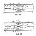
- FIGS. 3A-Care diagrams of an embodiment of a method.
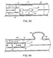
- FIGS. 4A-Care diagrams of an embodiment of a method.
- FIGS. 5A-Care diagrams of an embodiment of a method.
- FIG. 6is a partial cross-sectional view of an embodiment of an implantable medical endoprosthesis delivery system.
- FIG. 7is a partial cross-sectional view of an embodiment of an implantable medical endoprosthesis delivery system.
- FIG. 8is a partial cross-sectional view of an embodiment of an implantable medical endoprosthesis delivery system.
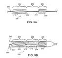
- FIG. 9Ais an embodiment of a guidewire.
- FIG. 9Bis an embodiment of an implantable medical endoprosthesis delivery system including the guidewire of FIG. 9A .
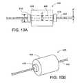
- FIG. 10Ais a cross-sectional view of an embodiment of a bumper on a delivery wire.
- FIG. 10Bis a perspective view of the embodiment of FIG. 11A .
- FIG. 11is a partial cross-sectional view of an implantable medical endoprosthesis delivery system.
- FIG. 12is a partial cross-sectional view of an embodiment of an implantable medical endoprosthesis delivery system.
- FIG. 1shows an implantable medical endoprosthesis delivery system 10 including a delivery wire 14 (e.g., a guide wire) within a catheter 16 , and a stent 12 disposed between the delivery wire 14 and the catheter 16 .
- Stent 12is typically a self-expanding stent, and is typically contained in the catheter 16 , which constrains stent 12 from expanding into its fully-expanded state.
- a first seating member 18 and a second seating member 20are disposed on the delivery wire 14 between the delivery wire 14 and the stent 12 .
- the first and second seating members 18 and 20each have a diameter such that seating surfaces 22 on each of the first and second members 18 and 20 contacts the stent 12 while the stent 12 is disposed within the catheter 16 .
- the seating members 18 and 20are configured, in conjunction with the configurations of the stent 12 and the catheter 16 , such that, when the stent is disposed on the seating members 18 and 20 and is disposed within the catheter 16 , the stent 12 will preferentially remain disposed on the seating members 18 and 20 when catheter 16 and seating members 18 and 20 are moved with respect to each other. In certain embodiments, this may be the result of a friction fit created by the contact between the stent 12 and the seating members 18 and 20 .
- the seating surfaces 22may have a coefficient of friction higher than that of the inner surface of the catheter 16 .
- the seating members 18 and 20 and/or the seating surfaces 22may be formed of a material which is at least partially deformable, for example, a soft, tacky, resilient, or elastomeric material, for example, a material having a durometer of from about 55 A to about 100 A (e.g., from about 60 A to about 90 A, from about 65 A to about 85 A, or from about 70 A to about 80 A) and/or from about 15 D to about 55 D (e.g., from about 20 D to about 50 D, from about 25 D to about 45 D, or from about 30 D to about 40 D).
- the durometer, or hardnessis measured in accordance with ASTM 2240.
- the stentis at least slightly pressed into the at least partially deformable seating member and/or seating surface.
- exemplary materialsinclude rubber, synthetic rubber, latex, polyurethane/silicone combinations such as, for example, Elast-EonTM polymers by AorTech, and other polymers such as, for example, [poly(styrene-b-. isobutylene-b-styrene)] (“SIBS”), or poly-(ether block amide), (e.g., PEBAX®).
- the seating surfacemay have one or more grooves into which the stent can be at least partially deployed.
- the stent 12as a result of the seating members and/or seating surfaces, remains substantially stationary with respect to the delivery wire 14 when the catheter 16 moves proximally or distally with respect to the delivery wire 14 .
- the stent 12remains substantially stationary with respect to the delivery wire 14 .
- Exemplary materials for forming the seating members 18 and 20 and/or the seating surfaces 22include rubber, synthetic rubber, latex, polyurethane/silicone combinations such as, for example, Elast-EonTM polymers, and other polymers such as, for example, [poly(styrene-b-.
- the seating surfaces 22may be formed of the same or a different material than the seating members 18 , 20 , and may make up an additional layer or component of the seating members 18 , 20 or may simply be the outer surface of each seating member rather than an additional component.
- the implantable medical endoprosthesis delivery system 10may further include a proximal bumper 26 disposed on the delivery wire 14 proximal to the stent 12 .
- the proximal bumper 26is configured to substantially prevent proximal movement of the stent 12 when the catheter 16 is moved proximally.
- the proximal bumper 26may also serve to help in pushing the stent 12 through the catheter 16 where such is desired.
- a bullet-shaped tip 28is connected to the delivery wire 14 distal of the stent 12 .
- the tip 28is configured to substantially prevent distal movement of the stent 12 when the catheter 16 is moved distally and to assist in the delivery of the catheter 16 , preloaded with the stent 12 , through body lumens to the position at which the stent 12 is to be deployed.
- the delivery wire 14can extend through the tip 28 such that a distal portion 29 of the delivery wire 14 extends beyond the tip 28 distally, for example, through a lumen (not illustrated) in the tip 28 .
- FIGS. 2 and 3illustrate a method utilizing implantable medical endoprosthesis delivery system 10 .
- implantable medical endoprosthesis delivery system 10is used as follows.
- System 10is positioned within a body lumen 30 (e.g., an artery) at a desired location, for example, adjacent an occlusion 35 .
- the stent 12is contained in an unexpanded state within the catheter 16 at a distal end 17 of the catheter 16 .
- the catheter 16serves to restrain the stent 12 from self-expanding at this point.
- the catheter 16is withdrawn (moved proximally) as indicated by arrows X in FIGS.
- a distal portion 12 a of the stent 12to expose or uncover a distal portion 12 a of the stent 12 .
- the distal portion 12 a of the stent 12When the distal portion 12 a of the stent 12 is uncovered (and thereby unrestrained from self-expansion), the distal portion self-expands towards a deployed diameter d, which is the diameter of the stent 12 when expanded in the body lumen 30 .
- the deployed diameter dis less than the diameter to which the stent 12 would expand absent the body lumen 30 . In this fashion, the stent 12 can continue to exert radial force, which can help to force open the occlusion and/or to maintain the position of the stent 12 within the body lumen 30 .
- the physicianmay desire to reposition the stent and/or system within lumen 30 , e.g., to select a more suitable location for the stent or to correct for errors in positioning resulting from the partial deployment of the stent.
- the physicianmay desire to entirely re-sheath and/or remove the stent (e.g., to replace it with a stent of, for example, a larger or smaller expanded diameter). Re-sheathing of the stent is possible, due at least in part to the presence of the second seating member 20 .
- the catheter 16can, as illustrated in FIG.
- the catheter 16can be further withdrawn as indicated by arrows Z to expose or uncover the remaining proximal portion 12 b of stent 12 .
- Stent 12can expand to the extent that the body lumen 30 permits once so exposed.
- FIGS. 4 and 5illustrate a similar method, utilizing implantable medical endoprosthesis delivery system 10 to block the opening of an aneurysm 335 and/or strengthen a vessel at the site of aneurysm 335 .
- System 10is positioned within a body lumen 330 (e.g., an artery) at a desired location, for example, adjacent aneurysm 335 .
- a body lumen 330e.g., an artery
- the stent 12is contained in an unexpanded state within the catheter 16 at a distal end 17 of the catheter 16 .
- the catheter 16is withdrawn (moved proximally) as indicated by arrows X in FIGS.
- a distal portion 12 a of the stent 12When the distal portion 12 a of the stent 12 is uncovered (and thereby unrestrained from self-expansion), the distal portion self-expands towards a deployed diameter d, which is the diameter of the stent 12 when expanded in the body lumen 330 .
- the physicianmay desire to reposition the stent and/or system within lumen 330 or to entirely re-sheath and remove the stent and replace it with a stent of, for example, a larger or smaller expanded diameter.
- the catheter 16can, as illustrated in FIG.
- the catheter 16can be further withdrawn as indicated by arrows Z to expose or uncover the remaining proximal portion 12 b of stent 12 .
- Stent 12can then expand to the extent that the body lumen 330 permits once so exposed, thereby at least partially occluding the opening 336 to the aneurysm 335 .
- an implantable medical endoprosthesis delivery system 100has a delivery wire 114 within catheter 116 , and a stent 112 disposed between the delivery wire 114 and the catheter 116 .
- a coating 118is disposed on the delivery wire 114 (e.g., a guide wire) between the delivery wire 114 and the stent 112 , with a coating surface 122 contacting the stent 112 .
- the coating surface 122is formed of a material that presses against or into the stent to force the stent to travel longitudinally, relative to the catheter, with the delivery wire.
- the coatingmay in certain embodiments be formed of a liquid or fluid material placed on or applied to the exterior of the wire and allowed to harden on the exterior of the wire, for example, sprayed on, brushed on, shrink-wrapped, and/or hot-dipped.
- the thickness of the coatingis selected based on the catheter inner diameter, stent thickness, and delivery wire diameter.
- the coatinghas a thickness of no less than about 0.05 mm (e.g., no less than about 0.10 mm, no less than about 0.15 mm, or no less than about 0.20 mm) and/or no more than about 0.25 mm (e.g., no more than about 0.20 mm, no more than about 0.15 mm, or no more than about 0.10 mm).
- the coatingmay in certain embodiments be a sleeve or a cylindrical plug of material having a central bore for receiving the delivery wire.
- the sleeve or pluggrips the delivery wire with sufficient force to ensure that it travels with the delivery wire.
- the coatingmay be a polymer coating, for example a thermoplastic coating (e.g., ElastEonTM) or may be a rubber, synthetic rubber, SIBS, or poly-(ether block amide) (e.g., PEBAX®).
- the coating thicknessis generally selected such that the coating will contact the endoprosthesis while the prosthesis is disposed within the delivery catheter and may be, for example, no less than about 3 ⁇ m thick (e.g., no less than about 50 ⁇ m thick, no less than about 100 ⁇ m thick, no less than about 150 ⁇ m thick, no less than about 200 ⁇ m thick, no less than about 250 ⁇ m thick, no less than about 300 ⁇ m thick, no less than about 350 ⁇ m thick, no less than about 400 ⁇ m thick, no less than about 450 ⁇ m thick, no less than about 500 ⁇ m thick, no less than about 550 ⁇ m thick, no less than about 600 ⁇ m thick, or no less than about 650 ⁇ m thick) and/or no more than about 700 ⁇ m thick (e.g., no more than about 650 ⁇ m thick, no more than about 600 ⁇ m thick, no more than about 550 ⁇ m thick, no more than about 500 ⁇ m thick, no more than about 450 ⁇ m
- Thisprovides for delivery wire/coating combinations having a diameter of no less than about 0.1 mm (e.g., no less than about 0.2 mm, no less than about 0.4 mm, no less than about 0.6 mm, no less than about 0.8 mm, or no less than about 1 mm) and/or no more than about 1.2 mm (e.g., no more than about 1 mm, no more than about 0.8 mm, no more than about 0.6 mm, no more than about 0.4 mm, or no more than about 0.2 mm).
- the coating 118 and the coating surface 122may be formed of the same or of different materials.
- the coating 118 and the coating surface 122may be contiguous, whereby the coating surface is formed of the outward-facing surface of the coating.
- the coating and coating surfaceare configured to retain the stent 112 in a substantially motionless position relative to the delivery wire 114 when the catheter 116 is moved proximally or distally and/or when the delivery wire 114 is moved proximally or distally.
- FIGS. 7 and 8illustrate other embodiments of implantable medical endoprosthesis delivery systems.
- An implantable medical endoprosthesis delivery system 150illustrated in FIG. 5 , has a delivery wire 154 within catheter 156 , and a stent 152 disposed between the delivery wire 154 and the catheter 156 .
- Windings 158are disposed on the delivery wire 154 between the delivery wire 154 and the stent 152 .
- the windingsmay be formed of a single strand of winding material, or optionally may be formed of multiple strands of winding material, for example, two, three or more strands of winding material.
- the windings 158may be formed from a winding material including a resilient material, e.g., a polymer, for example, ElastEonTM, poly-(ether block amide), (e.g., PEBAX®) or SIBS.
- the windingsmay be formed from an elastomeric material, e.g., a material having a durometer of at from about 65 A to about 55 D.
- the windingsmay extend substantially along the full length of the endoprosthesis, or may extend along a portion of the endoprosthesis. Multiple sections of windings may be included, e.g., two, three or more sections each supporting a portion of the endoprosthesis.
- the windings 158are sized to provide a windings diameter sufficient to apply a radial force to the stent 152 so that the stent 152 forms a friction fit with the catheter 156 to retain the stent 152 in a substantially motionless position relative to the delivery wire 154 when the catheter 156 is moved proximally or distally and/or when the delivery wire 154 is moved proximally or distally.
- the windingsmay form a mechanical grip with the struts of the stent, whereby the struts are at least partially disposed within the spaces between the windings.
- the windingsmay in certain embodiments have an average width (e.g., diameter, when the windings are cylindrical) of no less than about 3 ⁇ m (e.g., no less than about 50 ⁇ m, no less than about 100 ⁇ m, no less than about 150 ⁇ m, no less than about 200 ⁇ m, no less than about 250 ⁇ m, no less than about 300 ⁇ m, no less than about 350 ⁇ m, no less than about 400 ⁇ m, no less than about 450 ⁇ m, no less than about 500 ⁇ m, no less than about 550 ⁇ m, no less than about 600 ⁇ m, or no less than about 650 ⁇ m) and/or no more than about 700 ⁇ m (e.g., no more than about 650 ⁇ m, no more than about 600 ⁇ m, no more than about 550 ⁇ m, no more than about 500 ⁇ m, no more than about 450 ⁇ m, no more than about 400 ⁇ m, no more than about 350 ⁇ m, no more than about 3
- the windingsmay in certain embodiments have an average pitch (the length, measured longitudinally, of one full turn of the windings around the delivery wire) of no more than about 10 mm (e.g., no more than about 1 mm, no more than about 0.1 mm, or no more than about 0.05 mm) and/or no less than about 0.025 mm (e.g., no less than about 0.05 mm, no less than about 0.1 mm, or no less than about 1 mm).
- the windingsmay be placed on the delivery wire such that they are spaced apart from each other, which may impart greater flexibility to the delivery system. For example as illustrated in FIG.
- the ratio of an average pitch p of the windings to an average width w of the windingsmay be at least about 2 (e.g., at least about 2.5, at least about 3, at least about 3.5, at least about 4, at least about 4.5), and may be at most about 5 (e.g., at most about 4.5, at most about 4, at most about 3.5, at most about 3, at most about 2.5), and may be between about 2 and about 5 (e.g., between about 2.5 and about 4.5, between about 3 and about 4).
- the windings in certain embodimentsextend for an overall length of no more than about 35 mm (e.g., no more than about 30 mm, no more than about 25 mm, or no more than about 20 mm) and/or no less than about 15 mm (e.g., no less than about 20 mm, no less than about 25 mm, or no less than about 30 mm).
- multiple sections of windingscan be employed. Where multiple sections of winding are included, each section may have the same or different winding pitch, winding width, and/or ratio of the average pitch to the average width of the windings.
- FIG. 9Ashows a delivery wire 200 (e.g., a guidewire) which includes a wire 202 having a first portion 204 , a second portion 206 , and a third portion 208 disposed between the first and second portions 204 and 206 , respectively.
- Windings 210are disposed on the first portion 204 and the second portion 206 but the third portion 208 has no windings disposed thereupon.
- the windings 210are typically formed of a material that is different from the material that forms the wire 202 .
- windings 210may be any suitable material for achieving the desired stiffness/flexibility of the delivery wire, and may include, for example, metals, metal oxides, polymers, or plastics.
- the windings 210are generally sized to provide stent-contacting surfaces 214 that contact both ends of stent 212 so that the stent 212 is retained in a substantially motionless position relative to the delivery wire 200 when the catheter 216 is moved proximally or distally and/or when the delivery wire 200 is moved proximally or distally.
- the windingsmay have a diameter of no less than about 0.02 mm (e.g., no less than about 0.025 mm, no less than about 0.03 mm, no less than about 0.05 mm, or no less than about 1 mm) and/or no more than about 1.5 mm (e.g., no more than about 1 mm, no more than about 0.05 mm, no more than about 0.03 mm, no more than about 0.025 mm, or no more than about 0.02 mm).
- no less than about 0.02 mme.g., no less than about 0.025 mm, no less than about 0.03 mm, no less than about 0.05 mm, or no less than about 1 mm
- 1.5 mme.g., no more than about 1 mm, no more than about 0.05 mm, no more than about 0.03 mm, no more than about 0.025 mm, or no more than about 0.02 mm.
- Thisprovides for delivery wires having an overall diameter, inclusive of the windings, of no less than about 0.1 mm (e.g., no less than about 0.2 mm, no less than about 0.3 mm, no less than about 0.4 mm, no less than about 0.5 mm, no less than about 0.6 mm, no less than about 0.7 mm, no less than about 0.8 mm, or no less than about 0.9 mm) and/or no more than about 1.0 mm (e.g., no more than about 0.9 mm, no more than about 0.8 mm, no more than about 0.7 mm, no more than about 0.6 mm, no more than about 0.5 mm, no more than about 0.4 mm, no more than about 0.3 mm, no more than about 0.2 mm, or no more than about 0.1 mm).
- no less than about 0.1 mme.g., no less than about 0.2 mm, no less than about 0.3 mm, no less than about 0.4 mm, no less than about 0.5
- the third portion 208is generally configured to be at least as long as or slightly longer than the implantable endoprosthesis that is to be disposed around the third portion 208 .
- the third portionhas a length of at least about 0.5 cm (e.g., at least about 1 cm, at least about 2 cm, at least about 3 cm, at least about 4 cm, at least about 5 cm, at least about 6 cm, at least about 8 cm, or at least about 10 cm) and/or no more than about 15 cm (e.g., no more than about 10 cm, no more than about 8 cm, no more than about 6 cm, no more than about 5 cm, no more than about 4 cm, no more than about 3 cm, no more than about 2 cm, or no more than about 1 cm).
- FIG. 9BAn implantable medical endoprosthesis delivery system 220 including the delivery wire 200 is illustrated in FIG. 9B .
- a stent 212is disposed between the first portion 204 of the delivery wire 200 and a catheter 216 .
- the windings 210each have a stent-contacting surface 214 disposed on the end of the windings 210 that face the third section 208 of the delivery wire 200 .
- the third portion 208is sized to permit rotation or torque of the delivery wire 200 while applying substantially no torque to the stent 212 .
- the delivery wiremay further include a proximal bumper, a distal tip or bumper, or both, on the first and/or second portions and typically at the edge of the proximal and distal portions nearest the intermediate portion.
- a proximal bumper, a distal tip or bumper, or bothmay contact the stent in lieu of a stent-contacting surface of the windings, and would serve the same purpose, namely to hold the stent substantially motionless (in a proximal or distal direction) relative to the delivery wire.
- the third portion of the delivery wiremay have windings disposed thereupon, provided that the diameter of the third portion, inclusive of the optional windings, remains small enough to permit the delivery wire to be torqued without imparting torque to the stent.
- Such a configurationmay be desirable where additional stiffness is desired in the delivery wire, for example, where the endoprosthesis is particularly long (e.g. at least 25 mm long, at least 30 mm long, at least 35 mm long, at least 40 mm long, or at least 45 mm long).
- FIGS. 10A and 10Billustrate a delivery wire 400 (e.g., a guidewire) including a wire 402 having a member 404 (e.g., a seating member or a bumper) disposed thereon, in which the wire 402 can be rotated without causing the member 404 to rotate.
- the member 404has a lumen 406 through which the wire 402 passes.
- the lumen 406has a diameter d′ that is large enough to allow the wire 402 to rotate within the lumen 406 without applying substantial amounts of (e.g., without applying any) torque to the member 404 (e.g., d′ is larger than a diameter d′′ of the wire 402 ).
- a pair of sub-bumpers 410are attached (e.g., adhered) to the wire 402 at positions proximal and distal the member 404 .
- the sub-bumpers 410each have a diameter d′′′ that is larger than the diameter d′ of the lumen 406 in member 404 , such that the sub-bumpers can prevent the member 404 from moving proximally or distally along the wire 402 beyond either of the sub-bumpers 410 . In this fashion, the member 404 is retained laterally at a single position on wire 402 , but is not subject to torque when wire 402 is rotated (e.g., to steer wire 402 through a body lumen).
- the sub-bumpers 410are attached to the wire 402 such that the sub-bumpers 410 move laterally and rotationally with the wire 402 .
- the diameter d′′′ of the sub-bumpers 410is smaller than an outer diameter of the member 404 .
- FIG. 11illustrates an implantable medical endoprosthesis delivery system 420 that includes bumpers stent seating members that are not subject to torque when the delivery wire is rotated.
- the system 420includes a pair of bumpers 424 , each having a lumen 426 through which a wire 422 passes, the lumen 426 having a diameter larger than the diameter of the wire 422 .
- the bumpersare held in place laterally by two pairs of sub-bumpers 430 , each attached to the wire 422 such that they move laterally and rotationally along with the wire 422 .
- the sub-bumpers 430have a diameter larger than the diameter of the lumen 426 of the bumpers 424 .
- the bumpers 424are spaced apart from one another such that a stent 450 can be located between the bumpers 424 .
- the stent 450 and the delivery wire 422are contained in a catheter 428 , which constrains the stent 450 from expanding into its fully-expanded state.
- a seating member 438is disposed between the wire 422 and the stent 450 .
- the seating member 438has a lumen 440 through which the wire 422 passes, the lumen 440 having a diameter larger than the diameter of the wire 422 .
- the seating member 438is held in place laterally by two pairs of sub-bumpers 442 , each attached to the wire 422 such that they move laterally and rotationally along with the wire 422 .
- the sub-bumpers 442have a diameter larger than the diameter of the lumen 440 of the seating member 438 .
- the seating member 438has a diameter of sufficient size such that an outer (seating) surface 444 on the seating member 442 contacts the stent 450 while the stent 450 is disposed within the catheter 428 .
- the bumpers 424each have a diameter such that the bumper can contact a proximal edge 452 or a distal edge 454 of the stent 450 .
- Each of the sub-bumpers 430 and 442are sized to be larger than the lumen of the member (bumper 424 or seating member 438 ) that they abut while being small enough to avoid subjecting either the stent 450 or the catheter 428 to torque upon rotation of the wire 422 .
- an implantable medical endoprosthesismay be delivered using a delivery catheter rather than a delivery wire.
- an implantable medical endoprosthesis delivery system 50includes a delivery catheter 54 within outer catheter 56 , and a stent 52 disposed between the delivery catheter 54 and the outer catheter 56 .
- a first seating member 58 and second seating member 60are disposed on the delivery catheter 54 between the delivery catheter 54 and the stent 52 .
- the first and second seating members 58 and 60each have a diameter such that seating surfaces 62 on each of the first and second members 58 and 60 contacts the stent 52 .
- the first and second seating members 58 and 60are configured such that, when the outer catheter 56 moves proximally or distally with respect to the delivery catheter 54 , the stent 52 remains substantially stationary with respect to the delivery catheter 54 , while when the delivery catheter 54 moves proximally or distally, the stent 52 remains substantially stationary with respect to the delivery catheter 54 .
- the first and second seating members 58 and 60may be made of any of the materials disclosed above, and may include seating surfaces in accordance with those described above.
- a proximal bumper 66is disposed on the delivery catheter 54 proximal to the stent 52 and is configured to substantially prevent proximal movement of the stent 52 when the outer catheter 56 is moved proximally.
- the proximal bumper 66may also serve to help in pushing the stent 52 through the outer catheter 56 where such is desired.
- a bullet-shaped tip 68is connected to a distal end 55 of the delivery catheter 54 distal of the stent 52 and is configured to substantially prevent distal movement of the stent 52 when the outer catheter 56 is moved distally.
- the bullet-shaped tip 68includes a tip lumen 69 extending longitudinally therethrough to form, in conjunction with a lumen 53 in delivery catheter 54 , a lumen, e.g., through which a guidewire (not here illustrated) can extend.
- a seating membermay extend distally beyond the distal end of the delivery device and itself form a tip, e.g., a bullet shaped tip.
- the delivery wirecan in certain embodiments comprise a metal, an alloy (e.g., a stainless steel or Nitinol), or a polymer (e.g., a plastic).
- a metale.g., a stainless steel or Nitinol
- a polymere.g., a plastic
- the delivery membercan be formed of a tube, e.g., a tube having a spiral tube, attached (e.g., by adhesive or by weld) to the outside of the tube.
- the delivery membercan be a slotted hypotube, a rigid or semirigid tube having slots cut into it (e.g., by mechanical cutting or laser ablation).
- Such a delivery devicecan include an inner lumen while maintaining more flexibility than an unslotted tube.
- the catheter or sheath in which the endoprosthesis is containedmay be a microcatheter, e.g., the catheter may have a diameter of not more than about 5 french (e.g., not more than about 4 french, not more than about 3.5 french, not more than about 3 french, not more than about 2.5 french, not more than about 2.3 french, not more than about 2 french).
- an adhesivemay be interposed between the delivery wire or catheter and the seating members, coatings, and/or windings to ensure that the seating device travels with the delivery device.
- a seating membercan be a balloon that could be at least partially inflated to achieve a friction fit between itself and the endoprosthesis.
- a ballooncould optionally remain uninflated unless retraction of a partially-deployed endoprosthesis was desired, at which point it could be at least partially inflated to achieve a friction fit.
- the endoprostheses, delivery wires, catheters and/or guidewiresmay include one or more radiopaque materials, for example, one or more bands of radiopaque materials.
- any of the seating componentscan comprise a resilient and/or deformable material such that the endoprosthesis can press into it, forming a releasable mechanical grip with the seating member.
- the seating componentmay have a durometer of no more than 55 D (e.g., no more than 65 A).
- Exemplary resilient materialsinclude, for example, ElastEonTM, SIBS, or poly-(ether block amide), (e.g., PEBAX®).
- the seating surfacemay have a tacky consistency to which the endoprosthesis adheres, provided that substantially no material transfers from the seating surface to the stent.
- exemplary tacky seating surfacesinclude ElastEonTM, SIBS, or poly-(ether block amide), (e.g., PEBAX®).
- embodimentsWhile certain embodiments have been shown and/or described without a distal tip or a proximal bumper, embodiments generally can have a distal tip (e.g., a bullet-shaped distal tip) and/or a proximal bumper.
- a distal tipe.g., a bullet-shaped distal tip
- a proximal bumpere.g., a proximal bumper
Landscapes
- Health & Medical Sciences (AREA)
- Engineering & Computer Science (AREA)
- Biomedical Technology (AREA)
- Cardiology (AREA)
- Oral & Maxillofacial Surgery (AREA)
- Transplantation (AREA)
- Heart & Thoracic Surgery (AREA)
- Vascular Medicine (AREA)
- Life Sciences & Earth Sciences (AREA)
- Animal Behavior & Ethology (AREA)
- General Health & Medical Sciences (AREA)
- Public Health (AREA)
- Veterinary Medicine (AREA)
- Media Introduction/Drainage Providing Device (AREA)
Abstract
Description
Claims (30)
Priority Applications (6)
| Application Number | Priority Date | Filing Date | Title |
|---|---|---|---|
| US11/395,479US8092508B2 (en) | 2006-03-30 | 2006-03-30 | Implantable medical endoprosthesis delivery system |
| EP07759544.5AEP2004102B1 (en) | 2006-03-30 | 2007-03-28 | Implantable medical endoprosthesis delivery system |
| JP2009503232AJP2009532115A (en) | 2006-03-30 | 2007-03-28 | Implantable medical endoprosthesis delivery system |
| ES07759544.5TES2558845T3 (en) | 2006-03-30 | 2007-03-28 | Implantable medical stent delivery system |
| PCT/US2007/065327WO2007118005A1 (en) | 2006-03-30 | 2007-03-28 | Implantable medical endoprosthesis delivery system |
| US13/345,369US8506615B2 (en) | 2006-03-30 | 2012-01-06 | Implantable medical endoprosthesis delivery system |
Applications Claiming Priority (1)
| Application Number | Priority Date | Filing Date | Title |
|---|---|---|---|
| US11/395,479US8092508B2 (en) | 2006-03-30 | 2006-03-30 | Implantable medical endoprosthesis delivery system |
Related Child Applications (1)
| Application Number | Title | Priority Date | Filing Date |
|---|---|---|---|
| US13/345,369ContinuationUS8506615B2 (en) | 2006-03-30 | 2012-01-06 | Implantable medical endoprosthesis delivery system |
Publications (2)
| Publication Number | Publication Date |
|---|---|
| US20070233224A1 US20070233224A1 (en) | 2007-10-04 |
| US8092508B2true US8092508B2 (en) | 2012-01-10 |
Family
ID=38458199
Family Applications (2)
| Application Number | Title | Priority Date | Filing Date |
|---|---|---|---|
| US11/395,479Active2030-03-08US8092508B2 (en) | 2006-03-30 | 2006-03-30 | Implantable medical endoprosthesis delivery system |
| US13/345,369ActiveUS8506615B2 (en) | 2006-03-30 | 2012-01-06 | Implantable medical endoprosthesis delivery system |
Family Applications After (1)
| Application Number | Title | Priority Date | Filing Date |
|---|---|---|---|
| US13/345,369ActiveUS8506615B2 (en) | 2006-03-30 | 2012-01-06 | Implantable medical endoprosthesis delivery system |
Country Status (5)
| Country | Link |
|---|---|
| US (2) | US8092508B2 (en) |
| EP (1) | EP2004102B1 (en) |
| JP (1) | JP2009532115A (en) |
| ES (1) | ES2558845T3 (en) |
| WO (1) | WO2007118005A1 (en) |
Cited By (48)
| Publication number | Priority date | Publication date | Assignee | Title |
|---|---|---|---|---|
| US20090082800A1 (en)* | 2007-09-21 | 2009-03-26 | Insera Therapeutics Llc | Distal Embolic Protection Devices With A Variable Thickness Microguidewire And Methods For Their Use |
| US20110022152A1 (en)* | 2007-12-21 | 2011-01-27 | Axel Grandt | Double layered balloons in medical devices |
| US20110046711A1 (en)* | 2007-12-21 | 2011-02-24 | Nicolas Degen | Strengthening textures in medical devices |
| US8579958B2 (en) | 2002-03-12 | 2013-11-12 | Covidien Lp | Everting stent and stent delivery system |
| US8591566B2 (en) | 2012-02-23 | 2013-11-26 | Covidien Lp | Methods and apparatus for luminal stenting |
| US8679150B1 (en) | 2013-03-15 | 2014-03-25 | Insera Therapeutics, Inc. | Shape-set textile structure based mechanical thrombectomy methods |
| US8690907B1 (en) | 2013-03-15 | 2014-04-08 | Insera Therapeutics, Inc. | Vascular treatment methods |
| US8715317B1 (en) | 2013-07-29 | 2014-05-06 | Insera Therapeutics, Inc. | Flow diverting devices |
| US8808350B2 (en) | 2011-03-01 | 2014-08-19 | Endologix, Inc. | Catheter system and methods of using same |
| US9050205B2 (en) | 2004-05-25 | 2015-06-09 | Covidien Lp | Methods and apparatus for luminal stenting |
| US9072624B2 (en) | 2012-02-23 | 2015-07-07 | Covidien Lp | Luminal stenting |
| US9078659B2 (en) | 2012-04-23 | 2015-07-14 | Covidien Lp | Delivery system with hooks for resheathability |
| US9114001B2 (en) | 2012-10-30 | 2015-08-25 | Covidien Lp | Systems for attaining a predetermined porosity of a vascular device |
| US9125659B2 (en) | 2004-05-25 | 2015-09-08 | Covidien Lp | Flexible vascular occluding device |
| US9157174B2 (en) | 2013-02-05 | 2015-10-13 | Covidien Lp | Vascular device for aneurysm treatment and providing blood flow into a perforator vessel |
| US9174020B2 (en) | 2013-05-08 | 2015-11-03 | Embolx, Inc. | Device and methods for transvascular tumor embolization with integrated flow regulation |
| US9314324B2 (en) | 2013-03-15 | 2016-04-19 | Insera Therapeutics, Inc. | Vascular treatment devices and methods |
| US9320590B2 (en) | 2006-02-22 | 2016-04-26 | Covidien Lp | Stents having radiopaque mesh |
| US9393021B2 (en) | 2004-05-25 | 2016-07-19 | Covidien Lp | Flexible vascular occluding device |
| US9452070B2 (en) | 2012-10-31 | 2016-09-27 | Covidien Lp | Methods and systems for increasing a density of a region of a vascular device |
| US9474639B2 (en) | 2013-08-27 | 2016-10-25 | Covidien Lp | Delivery of medical devices |
| US9550046B1 (en) | 2016-02-16 | 2017-01-24 | Embolx, Inc. | Balloon catheter and methods of fabrication and use |
| US9700701B2 (en) | 2008-07-01 | 2017-07-11 | Endologix, Inc. | Catheter system and methods of using same |
| US9724222B2 (en) | 2012-07-20 | 2017-08-08 | Covidien Lp | Resheathable stent delivery system |
| US9782186B2 (en) | 2013-08-27 | 2017-10-10 | Covidien Lp | Vascular intervention system |
| US9844383B2 (en) | 2013-05-08 | 2017-12-19 | Embolx, Inc. | Devices and methods for low pressure tumor embolization |
| US9943427B2 (en) | 2012-11-06 | 2018-04-17 | Covidien Lp | Shaped occluding devices and methods of using the same |
| US10004618B2 (en) | 2004-05-25 | 2018-06-26 | Covidien Lp | Methods and apparatus for luminal stenting |
| US10130500B2 (en) | 2013-07-25 | 2018-11-20 | Covidien Lp | Methods and apparatus for luminal stenting |
| US10350382B1 (en) | 2018-06-08 | 2019-07-16 | Embolx, Inc. | High torque catheter and methods of manufacture |
| US10376396B2 (en) | 2017-01-19 | 2019-08-13 | Covidien Lp | Coupling units for medical device delivery systems |
| US10390926B2 (en) | 2013-07-29 | 2019-08-27 | Insera Therapeutics, Inc. | Aspiration devices and methods |
| US10390982B1 (en) | 2018-11-13 | 2019-08-27 | Icad Endovascular Llc | Systems and methods for delivery retrievable stents |
| US10537344B2 (en) | 2015-10-23 | 2020-01-21 | Covidien Lp | Rotatable connection between an intervention member and a manipulation member of an endovascular device |
| US10786377B2 (en) | 2018-04-12 | 2020-09-29 | Covidien Lp | Medical device delivery |
| US20210196490A1 (en)* | 2018-04-12 | 2021-07-01 | Covidien Lp | Medical device delivery |
| US11123209B2 (en) | 2018-04-12 | 2021-09-21 | Covidien Lp | Medical device delivery |
| US11129737B2 (en) | 2015-06-30 | 2021-09-28 | Endologix Llc | Locking assembly for coupling guidewire to delivery system |
| US11413176B2 (en) | 2018-04-12 | 2022-08-16 | Covidien Lp | Medical device delivery |
| US11413174B2 (en) | 2019-06-26 | 2022-08-16 | Covidien Lp | Core assembly for medical device delivery systems |
| US11464948B2 (en) | 2016-02-16 | 2022-10-11 | Embolx, Inc. | Balloon catheters and methods of manufacture and use |
| US11944558B2 (en) | 2021-08-05 | 2024-04-02 | Covidien Lp | Medical device delivery devices, systems, and methods |
| US12042413B2 (en) | 2021-04-07 | 2024-07-23 | Covidien Lp | Delivery of medical devices |
| US12090072B2 (en) | 2018-11-13 | 2024-09-17 | Icad Endovascular Llc | Systems and methods for delivery retrievable stents |
| US12109137B2 (en) | 2021-07-30 | 2024-10-08 | Covidien Lp | Medical device delivery |
| US12121460B2 (en) | 2010-05-27 | 2024-10-22 | Idev Technologies, Inc. | Stent delivery system with pusher assembly |
| US12268824B2 (en) | 2018-07-27 | 2025-04-08 | Embolx, Inc. | Shaped catheter tip for tracking over a guidewire through turns in the vasculature |
| US12409298B2 (en) | 2019-08-20 | 2025-09-09 | Embolx, Inc. | Catheters and methods of manufacture and use |
Families Citing this family (67)
| Publication number | Priority date | Publication date | Assignee | Title |
|---|---|---|---|---|
| US7018401B1 (en) | 1999-02-01 | 2006-03-28 | Board Of Regents, The University Of Texas System | Woven intravascular devices and methods for making the same and apparatus for delivery of the same |
| MX2009004291A (en) | 2006-10-22 | 2009-09-07 | Idev Technologies Inc | Methods for securing strand ends and the resulting devices. |
| KR101659197B1 (en) | 2006-10-22 | 2016-09-22 | 이데브 테크놀로지스, 아이엔씨. | Devices and methods for stent advancement |
| US20100256600A1 (en)* | 2009-04-04 | 2010-10-07 | Ferrera David A | Neurovascular otw pta balloon catheter and delivery system |
| EP2633823B1 (en) | 2008-04-21 | 2016-06-01 | Covidien LP | Braid-ball embolic devices and delivery systems |
| US8992591B2 (en)* | 2008-05-07 | 2015-03-31 | Cook Medical Technologies Llc | Delivery system with low longitudinal compressibility |
| WO2009140437A1 (en)* | 2008-05-13 | 2009-11-19 | Nfocus Neuromedical, Inc. | Braid implant delivery systems |
| US9750625B2 (en) | 2008-06-11 | 2017-09-05 | C.R. Bard, Inc. | Catheter delivery device |
| GB0810749D0 (en) | 2008-06-11 | 2008-07-16 | Angiomed Ag | Catherter delivery device |
| US20120310321A1 (en)* | 2009-10-05 | 2012-12-06 | Bradley Beach | Reconstrainable stent delivery system |
| US9149376B2 (en)* | 2008-10-06 | 2015-10-06 | Cordis Corporation | Reconstrainable stent delivery system |
| US20100274276A1 (en)* | 2009-04-22 | 2010-10-28 | Ricky Chow | Aneurysm treatment system, device and method |
| WO2011094638A1 (en) | 2010-01-28 | 2011-08-04 | Micro Therapeutics, Inc. | Vascular remodeling device |
| WO2011122444A1 (en)* | 2010-03-30 | 2011-10-06 | テルモ株式会社 | Stent delivery system |
| US10130470B2 (en) | 2010-08-17 | 2018-11-20 | St. Jude Medical, Llc | Sleeve for facilitating movement of a transfemoral catheter |
| JP2013540481A (en) | 2010-09-17 | 2013-11-07 | セント・ジュード・メディカル,カーディオロジー・ディヴィジョン,インコーポレイテッド | Retainer for transcatheter heart valve delivery system |
| US9414944B2 (en)* | 2010-11-11 | 2016-08-16 | W. L. Gore & Associates, Inc. | Deployment sleeve shortening mechanism |
| JP5868432B2 (en) | 2011-02-11 | 2016-02-24 | コヴィディエン リミテッド パートナーシップ | Two-stage deployed aneurysm embolization device |
| US8831741B2 (en)* | 2011-03-14 | 2014-09-09 | Medtronic Vascular, Inc. | Catheter with deflectable cap |
| US20120245674A1 (en) | 2011-03-25 | 2012-09-27 | Tyco Healthcare Group Lp | Vascular remodeling device |
| EP2736450A1 (en) | 2011-07-28 | 2014-06-04 | St. Jude Medical, Inc. | Expandable radiopaque marker for transcatheter aortic valve implantation |
| US9060886B2 (en) | 2011-09-29 | 2015-06-23 | Covidien Lp | Vascular remodeling device |
| US10028854B2 (en) | 2012-02-02 | 2018-07-24 | Covidien Lp | Stent retaining systems |
| WO2013119332A2 (en) | 2012-02-09 | 2013-08-15 | Stout Medical Group, L.P. | Embolic device and methods of use |
| EP2628470B1 (en)* | 2012-02-16 | 2020-11-25 | Biotronik AG | Release device for releasing a medical implant from a catheter and catheter having a release device and method for clamping an implant therein |
| US9480561B2 (en) | 2012-06-26 | 2016-11-01 | St. Jude Medical, Cardiology Division, Inc. | Apparatus and method for aortic protection and TAVI planar alignment |
| US9918837B2 (en) | 2012-06-29 | 2018-03-20 | St. Jude Medical, Cardiology Division, Inc. | System to assist in the release of a collapsible stent from a delivery device |
| JP6057584B2 (en)* | 2012-07-24 | 2017-01-11 | 株式会社カネカ | Self-expanding stent delivery system and manufacturing method thereof |
| US9314248B2 (en) | 2012-11-06 | 2016-04-19 | Covidien Lp | Multi-pivot thrombectomy device |
| US9295571B2 (en)* | 2013-01-17 | 2016-03-29 | Covidien Lp | Methods and apparatus for luminal stenting |
| US10603157B2 (en) | 2013-03-13 | 2020-03-31 | DePuy Synthes Products, Inc. | Braid implant delivery and retraction device with distal engagement |
| US10561509B2 (en)* | 2013-03-13 | 2020-02-18 | DePuy Synthes Products, Inc. | Braided stent with expansion ring and method of delivery |
| US9855160B2 (en)* | 2013-03-14 | 2018-01-02 | W. L. Gore & Associates, Inc. | Endoprosthesis delivery systems with deployment aids |
| US9463105B2 (en)* | 2013-03-14 | 2016-10-11 | Covidien Lp | Methods and apparatus for luminal stenting |
| US10736758B2 (en) | 2013-03-15 | 2020-08-11 | Covidien | Occlusive device |
| US9265551B2 (en) | 2013-07-19 | 2016-02-23 | Pro-Dex, Inc. | Torque-limiting screwdrivers |
| JP6241969B2 (en) | 2014-05-28 | 2017-12-06 | ストライカー ヨーロピアン ホールディングス I,エルエルシーStryker European Holdings I,Llc | Vascular occlusion device and method of use thereof |
| US9060777B1 (en) | 2014-05-28 | 2015-06-23 | Tw Medical Technologies, Llc | Vaso-occlusive devices and methods of use |
| US10206796B2 (en) | 2014-08-27 | 2019-02-19 | DePuy Synthes Products, Inc. | Multi-strand implant with enhanced radiopacity |
| US9433520B2 (en) | 2015-01-29 | 2016-09-06 | Intact Vascular, Inc. | Delivery device and method of delivery |
| US9375336B1 (en)* | 2015-01-29 | 2016-06-28 | Intact Vascular, Inc. | Delivery device and method of delivery |
| CN105832453A (en) | 2015-01-31 | 2016-08-10 | 灵活支架解决方案股份有限公司 | Reconstrainable stent delivery system with a proximal stop and an annular lock distal to the proximal stop and method |
| US10159490B2 (en) | 2015-05-08 | 2018-12-25 | Stryker European Holdings I, Llc | Vaso-occlusive devices |
| WO2017023527A1 (en) | 2015-08-03 | 2017-02-09 | Advanced Endovascular Therapeutics | Novel coatings for medical devices |
| JP6854282B2 (en)* | 2015-09-18 | 2021-04-07 | テルモ株式会社 | Pressable implant delivery system |
| US10478194B2 (en) | 2015-09-23 | 2019-11-19 | Covidien Lp | Occlusive devices |
| US10993824B2 (en) | 2016-01-01 | 2021-05-04 | Intact Vascular, Inc. | Delivery device and method of delivery |
| US10881542B2 (en)* | 2016-04-05 | 2021-01-05 | Boston Scientific Scimed, Inc. | Stent delivery device |
| US10667907B2 (en) | 2016-05-13 | 2020-06-02 | St. Jude Medical, Cardiology Division, Inc. | Systems and methods for device implantation |
| WO2017214194A1 (en) | 2016-06-07 | 2017-12-14 | Pro-Dex, Inc. | Torque-limiting screwdriver devices, systems, and methods |
| US10076428B2 (en) | 2016-08-25 | 2018-09-18 | DePuy Synthes Products, Inc. | Expansion ring for a braided stent |
| US10292851B2 (en) | 2016-09-30 | 2019-05-21 | DePuy Synthes Products, Inc. | Self-expanding device delivery apparatus with dual function bump |
| EP3585305B1 (en) | 2017-02-23 | 2025-07-30 | Boston Scientific Scimed, Inc. | Medical drain device |
| US11660218B2 (en) | 2017-07-26 | 2023-05-30 | Intact Vascular, Inc. | Delivery device and method of delivery |
| CN111031971B (en)* | 2017-08-23 | 2021-11-19 | 斯瑞克公司 | Implant Delivery System |
| JP7377214B2 (en)* | 2018-04-12 | 2023-11-09 | コヴィディエン リミテッド パートナーシップ | Medical device delivery |
| AU2019204522A1 (en) | 2018-07-30 | 2020-02-13 | DePuy Synthes Products, Inc. | Systems and methods of manufacturing and using an expansion ring |
| US10278848B1 (en) | 2018-08-06 | 2019-05-07 | DePuy Synthes Products, Inc. | Stent delivery with expansion assisting delivery wire |
| US10456280B1 (en) | 2018-08-06 | 2019-10-29 | DePuy Synthes Products, Inc. | Systems and methods of using a braided implant |
| CN112566754B (en) | 2018-08-20 | 2023-04-18 | 普罗德克斯有限公司 | Torque limiting device, system and method |
| US11039944B2 (en) | 2018-12-27 | 2021-06-22 | DePuy Synthes Products, Inc. | Braided stent system with one or more expansion rings |
| CN110169852B (en)* | 2019-07-01 | 2024-03-19 | 江苏暖阳医疗器械有限公司 | Double-guide-wire conveying system of self-expanding bracket |
| CN112842647A (en)* | 2019-11-27 | 2021-05-28 | 微创神通医疗科技(上海)有限公司 | Delivery guide wire and treatment device |
| EP3875057B1 (en)* | 2020-03-04 | 2024-07-17 | Life Seal Vascular, Inc. | Catheter system for delivery of a filling body to an aneurysmal sac in a body lumen |
| CN113796987B (en)* | 2020-10-12 | 2025-04-08 | 宁波健世科技股份有限公司 | Conveying system capable of buffering and releasing implantation instrument |
| CN116849750B (en)* | 2023-09-02 | 2023-11-21 | 杭州亿科医疗科技有限公司 | Aneurysm turbulent flow device capable of being mechanically released |
| CN116849749B (en)* | 2023-09-02 | 2023-11-17 | 杭州亿科医疗科技有限公司 | Aneurysm vortex device with retractable vortex net |
Citations (20)
| Publication number | Priority date | Publication date | Assignee | Title |
|---|---|---|---|---|
| US5026377A (en) | 1989-07-13 | 1991-06-25 | American Medical Systems, Inc. | Stent placement instrument and method |
| US5437288A (en) | 1992-09-04 | 1995-08-01 | Mayo Foundation For Medical Education And Research | Flexible catheter guidewire |
| US5534077A (en) | 1991-12-11 | 1996-07-09 | Lichtblau; Josef | Method and an apparatus for the disposal of foam materials containing propellants and more particularly of foam materials such as polyurethane employed as insulating material for refrigeration devices |
| US5645559A (en) | 1992-05-08 | 1997-07-08 | Schneider (Usa) Inc | Multiple layer stent |
| US5741429A (en) | 1991-09-05 | 1998-04-21 | Cardia Catheter Company | Flexible tubular device for use in medical applications |
| US5772669A (en) | 1996-09-27 | 1998-06-30 | Scimed Life Systems, Inc. | Stent deployment catheter with retractable sheath |
| US5833632A (en) | 1995-12-07 | 1998-11-10 | Sarcos, Inc. | Hollow guide wire apparatus catheters |
| US6120522A (en)* | 1998-08-27 | 2000-09-19 | Scimed Life Systems, Inc. | Self-expanding stent delivery catheter |
| US6231598B1 (en)* | 1997-09-24 | 2001-05-15 | Med Institute, Inc. | Radially expandable stent |
| US6315790B1 (en) | 1999-06-07 | 2001-11-13 | Scimed Life Systems, Inc. | Radiopaque marker bands |
| US6342066B1 (en) | 1995-06-07 | 2002-01-29 | Scimed Life Systems, Inc. | Pull back sleeve system with compression resistant inner shaft |
| US6425898B1 (en) | 1998-03-13 | 2002-07-30 | Cordis Corporation | Delivery apparatus for a self-expanding stent |
| US6428489B1 (en) | 1995-12-07 | 2002-08-06 | Precision Vascular Systems, Inc. | Guidewire system |
| US20030109886A1 (en) | 2001-06-27 | 2003-06-12 | Martin Keegan | Catheter |
| US6602226B1 (en) | 2000-10-12 | 2003-08-05 | Scimed Life Systems, Inc. | Low-profile stent delivery system and apparatus |
| US6620191B1 (en) | 2001-03-27 | 2003-09-16 | Advanced Cardiovascular Systems, Inc. | System for releasably securing a stent on a catheter assembly and method of use |
| US6676667B2 (en) | 1999-03-31 | 2004-01-13 | Scimed Life Systems, Inc. | Stent security balloon/balloon catheter |
| US6743219B1 (en) | 2000-08-02 | 2004-06-01 | Cordis Corporation | Delivery apparatus for a self-expanding stent |
| US20060058865A1 (en)* | 2004-08-26 | 2006-03-16 | Case Brian C | Delivery system with controlled frictional properties |
| US7367989B2 (en)* | 2003-02-27 | 2008-05-06 | Scimed Life Systems, Inc. | Rotating balloon expandable sheath bifurcation delivery |
Family Cites Families (8)
| Publication number | Priority date | Publication date | Assignee | Title |
|---|---|---|---|---|
| US5797952A (en)* | 1996-06-21 | 1998-08-25 | Localmed, Inc. | System and method for delivering helical stents |
| US5980530A (en)* | 1996-08-23 | 1999-11-09 | Scimed Life Systems Inc | Stent delivery system |
| EP0948935B1 (en)* | 1997-10-30 | 2007-09-05 | Kaneka Medix Corporation | Medical implement for depositing implantable device |
| EP0943300A1 (en)* | 1998-03-17 | 1999-09-22 | Medicorp S.A. | Reversible action endoprosthesis delivery device. |
| JP3756002B2 (en)* | 1998-10-29 | 2006-03-15 | 株式会社リコー | CLV optical disc |
| US6592592B1 (en) | 1999-04-19 | 2003-07-15 | Advanced Cardiovascular Systems, Inc. | Delivery system for balloon expandable stent |
| US6699274B2 (en)* | 2001-01-22 | 2004-03-02 | Scimed Life Systems, Inc. | Stent delivery system and method of manufacturing same |
| US6833003B2 (en)* | 2002-06-24 | 2004-12-21 | Cordis Neurovascular | Expandable stent and delivery system |
- 2006
- 2006-03-30USUS11/395,479patent/US8092508B2/enactiveActive
- 2007
- 2007-03-28ESES07759544.5Tpatent/ES2558845T3/enactiveActive
- 2007-03-28JPJP2009503232Apatent/JP2009532115A/enactivePending
- 2007-03-28WOPCT/US2007/065327patent/WO2007118005A1/enactiveApplication Filing
- 2007-03-28EPEP07759544.5Apatent/EP2004102B1/enactiveActive
- 2012
- 2012-01-06USUS13/345,369patent/US8506615B2/enactiveActive
Patent Citations (20)
| Publication number | Priority date | Publication date | Assignee | Title |
|---|---|---|---|---|
| US5026377A (en) | 1989-07-13 | 1991-06-25 | American Medical Systems, Inc. | Stent placement instrument and method |
| US5741429A (en) | 1991-09-05 | 1998-04-21 | Cardia Catheter Company | Flexible tubular device for use in medical applications |
| US5534077A (en) | 1991-12-11 | 1996-07-09 | Lichtblau; Josef | Method and an apparatus for the disposal of foam materials containing propellants and more particularly of foam materials such as polyurethane employed as insulating material for refrigeration devices |
| US5645559A (en) | 1992-05-08 | 1997-07-08 | Schneider (Usa) Inc | Multiple layer stent |
| US5437288A (en) | 1992-09-04 | 1995-08-01 | Mayo Foundation For Medical Education And Research | Flexible catheter guidewire |
| US6342066B1 (en) | 1995-06-07 | 2002-01-29 | Scimed Life Systems, Inc. | Pull back sleeve system with compression resistant inner shaft |
| US5833632A (en) | 1995-12-07 | 1998-11-10 | Sarcos, Inc. | Hollow guide wire apparatus catheters |
| US6428489B1 (en) | 1995-12-07 | 2002-08-06 | Precision Vascular Systems, Inc. | Guidewire system |
| US5772669A (en) | 1996-09-27 | 1998-06-30 | Scimed Life Systems, Inc. | Stent deployment catheter with retractable sheath |
| US6231598B1 (en)* | 1997-09-24 | 2001-05-15 | Med Institute, Inc. | Radially expandable stent |
| US6425898B1 (en) | 1998-03-13 | 2002-07-30 | Cordis Corporation | Delivery apparatus for a self-expanding stent |
| US6120522A (en)* | 1998-08-27 | 2000-09-19 | Scimed Life Systems, Inc. | Self-expanding stent delivery catheter |
| US6676667B2 (en) | 1999-03-31 | 2004-01-13 | Scimed Life Systems, Inc. | Stent security balloon/balloon catheter |
| US6315790B1 (en) | 1999-06-07 | 2001-11-13 | Scimed Life Systems, Inc. | Radiopaque marker bands |
| US6743219B1 (en) | 2000-08-02 | 2004-06-01 | Cordis Corporation | Delivery apparatus for a self-expanding stent |
| US6602226B1 (en) | 2000-10-12 | 2003-08-05 | Scimed Life Systems, Inc. | Low-profile stent delivery system and apparatus |
| US6620191B1 (en) | 2001-03-27 | 2003-09-16 | Advanced Cardiovascular Systems, Inc. | System for releasably securing a stent on a catheter assembly and method of use |
| US20030109886A1 (en) | 2001-06-27 | 2003-06-12 | Martin Keegan | Catheter |
| US7367989B2 (en)* | 2003-02-27 | 2008-05-06 | Scimed Life Systems, Inc. | Rotating balloon expandable sheath bifurcation delivery |
| US20060058865A1 (en)* | 2004-08-26 | 2006-03-16 | Case Brian C | Delivery system with controlled frictional properties |
Non-Patent Citations (1)
| Title |
|---|
| International Preliminary Report on Patentability; PCT/US2007/065327; mailed Oct. 9, 2008. |
Cited By (148)
| Publication number | Priority date | Publication date | Assignee | Title |
|---|---|---|---|---|
| US8579958B2 (en) | 2002-03-12 | 2013-11-12 | Covidien Lp | Everting stent and stent delivery system |
| US9849014B2 (en) | 2002-03-12 | 2017-12-26 | Covidien Lp | Medical device delivery |
| US10004618B2 (en) | 2004-05-25 | 2018-06-26 | Covidien Lp | Methods and apparatus for luminal stenting |
| US9295568B2 (en) | 2004-05-25 | 2016-03-29 | Covidien Lp | Methods and apparatus for luminal stenting |
| US9050205B2 (en) | 2004-05-25 | 2015-06-09 | Covidien Lp | Methods and apparatus for luminal stenting |
| US9855047B2 (en) | 2004-05-25 | 2018-01-02 | Covidien Lp | Flexible vascular occluding device |
| US10918389B2 (en) | 2004-05-25 | 2021-02-16 | Covidien Lp | Flexible vascular occluding device |
| US10765542B2 (en) | 2004-05-25 | 2020-09-08 | Covidien Lp | Methods and apparatus for luminal stenting |
| US9393021B2 (en) | 2004-05-25 | 2016-07-19 | Covidien Lp | Flexible vascular occluding device |
| US11771433B2 (en) | 2004-05-25 | 2023-10-03 | Covidien Lp | Flexible vascular occluding device |
| US9801744B2 (en) | 2004-05-25 | 2017-10-31 | Covidien Lp | Methods and apparatus for luminal stenting |
| US12042411B2 (en) | 2004-05-25 | 2024-07-23 | Covidien Lp | Methods and apparatus for luminal stenting |
| US9125659B2 (en) | 2004-05-25 | 2015-09-08 | Covidien Lp | Flexible vascular occluding device |
| US9320590B2 (en) | 2006-02-22 | 2016-04-26 | Covidien Lp | Stents having radiopaque mesh |
| US9610181B2 (en) | 2006-02-22 | 2017-04-04 | Covidien Lp | Stents having radiopaque mesh |
| US10433988B2 (en) | 2006-02-22 | 2019-10-08 | Covidien Lp | Stents having radiopaque mesh |
| US11382777B2 (en) | 2006-02-22 | 2022-07-12 | Covidien Lp | Stents having radiopaque mesh |
| US20090082800A1 (en)* | 2007-09-21 | 2009-03-26 | Insera Therapeutics Llc | Distal Embolic Protection Devices With A Variable Thickness Microguidewire And Methods For Their Use |
| US9034007B2 (en) | 2007-09-21 | 2015-05-19 | Insera Therapeutics, Inc. | Distal embolic protection devices with a variable thickness microguidewire and methods for their use |
| US9717615B2 (en)* | 2007-12-21 | 2017-08-01 | Abbott Laboratories Vascular Enterprises | Double layered balloons in medical devices |
| US20110046711A1 (en)* | 2007-12-21 | 2011-02-24 | Nicolas Degen | Strengthening textures in medical devices |
| US20110022152A1 (en)* | 2007-12-21 | 2011-01-27 | Axel Grandt | Double layered balloons in medical devices |
| US9700701B2 (en) | 2008-07-01 | 2017-07-11 | Endologix, Inc. | Catheter system and methods of using same |
| US10512758B2 (en) | 2008-07-01 | 2019-12-24 | Endologix, Inc. | Catheter system and methods of using same |
| US12121460B2 (en) | 2010-05-27 | 2024-10-22 | Idev Technologies, Inc. | Stent delivery system with pusher assembly |
| US8808350B2 (en) | 2011-03-01 | 2014-08-19 | Endologix, Inc. | Catheter system and methods of using same |
| US12239558B2 (en) | 2011-03-01 | 2025-03-04 | Endologix Llc | Catheter system and methods of using same |
| US9687374B2 (en) | 2011-03-01 | 2017-06-27 | Endologix, Inc. | Catheter system and methods of using same |
| US9549835B2 (en) | 2011-03-01 | 2017-01-24 | Endologix, Inc. | Catheter system and methods of using same |
| US10660775B2 (en) | 2011-03-01 | 2020-05-26 | Endologix, Inc. | Catheter system and methods of using same |
| US10537452B2 (en) | 2012-02-23 | 2020-01-21 | Covidien Lp | Luminal stenting |
| US8591566B2 (en) | 2012-02-23 | 2013-11-26 | Covidien Lp | Methods and apparatus for luminal stenting |
| US9675488B2 (en) | 2012-02-23 | 2017-06-13 | Covidien Lp | Luminal stenting |
| US11259946B2 (en) | 2012-02-23 | 2022-03-01 | Covidien Lp | Luminal stenting |
| US9724221B2 (en) | 2012-02-23 | 2017-08-08 | Covidien Lp | Luminal stenting |
| US9192498B2 (en) | 2012-02-23 | 2015-11-24 | Covidien Lp | Luminal stenting |
| US9072624B2 (en) | 2012-02-23 | 2015-07-07 | Covidien Lp | Luminal stenting |
| US9308110B2 (en) | 2012-02-23 | 2016-04-12 | Covidien Lp | Luminal stenting |
| US9949853B2 (en) | 2012-04-23 | 2018-04-24 | Covidien Lp | Delivery system with hooks for resheathability |
| US9078659B2 (en) | 2012-04-23 | 2015-07-14 | Covidien Lp | Delivery system with hooks for resheathability |
| US9724222B2 (en) | 2012-07-20 | 2017-08-08 | Covidien Lp | Resheathable stent delivery system |
| US9907643B2 (en) | 2012-10-30 | 2018-03-06 | Covidien Lp | Systems for attaining a predetermined porosity of a vascular device |
| US9301831B2 (en) | 2012-10-30 | 2016-04-05 | Covidien Lp | Methods for attaining a predetermined porosity of a vascular device |
| US9114001B2 (en) | 2012-10-30 | 2015-08-25 | Covidien Lp | Systems for attaining a predetermined porosity of a vascular device |
| US10206798B2 (en) | 2012-10-31 | 2019-02-19 | Covidien Lp | Methods and systems for increasing a density of a region of a vascular device |
| US10952878B2 (en) | 2012-10-31 | 2021-03-23 | Covidien Lp | Methods and systems for increasing a density of a region of a vascular device |
| US9452070B2 (en) | 2012-10-31 | 2016-09-27 | Covidien Lp | Methods and systems for increasing a density of a region of a vascular device |
| US9943427B2 (en) | 2012-11-06 | 2018-04-17 | Covidien Lp | Shaped occluding devices and methods of using the same |
| US9157174B2 (en) | 2013-02-05 | 2015-10-13 | Covidien Lp | Vascular device for aneurysm treatment and providing blood flow into a perforator vessel |
| US9561122B2 (en) | 2013-02-05 | 2017-02-07 | Covidien Lp | Vascular device for aneurysm treatment and providing blood flow into a perforator vessel |
| US11298144B2 (en) | 2013-03-15 | 2022-04-12 | Insera Therapeutics, Inc. | Thrombus aspiration facilitation systems |
| US8733618B1 (en) | 2013-03-15 | 2014-05-27 | Insera Therapeutics, Inc. | Methods of coupling parts of vascular treatment systems |
| US8679150B1 (en) | 2013-03-15 | 2014-03-25 | Insera Therapeutics, Inc. | Shape-set textile structure based mechanical thrombectomy methods |
| US9179995B2 (en) | 2013-03-15 | 2015-11-10 | Insera Therapeutics, Inc. | Methods of manufacturing slotted vascular treatment devices |
| US9179931B2 (en) | 2013-03-15 | 2015-11-10 | Insera Therapeutics, Inc. | Shape-set textile structure based mechanical thrombectomy systems |
| US8910555B2 (en) | 2013-03-15 | 2014-12-16 | Insera Therapeutics, Inc. | Non-cylindrical mandrels |
| US8690907B1 (en) | 2013-03-15 | 2014-04-08 | Insera Therapeutics, Inc. | Vascular treatment methods |
| US8904914B2 (en) | 2013-03-15 | 2014-12-09 | Insera Therapeutics, Inc. | Methods of using non-cylindrical mandrels |
| US8895891B2 (en) | 2013-03-15 | 2014-11-25 | Insera Therapeutics, Inc. | Methods of cutting tubular devices |
| US8882797B2 (en) | 2013-03-15 | 2014-11-11 | Insera Therapeutics, Inc. | Methods of embolic filtering |
| US9314324B2 (en) | 2013-03-15 | 2016-04-19 | Insera Therapeutics, Inc. | Vascular treatment devices and methods |
| US10251739B2 (en) | 2013-03-15 | 2019-04-09 | Insera Therapeutics, Inc. | Thrombus aspiration using an operator-selectable suction pattern |
| US10335260B2 (en) | 2013-03-15 | 2019-07-02 | Insera Therapeutics, Inc. | Methods of treating a thrombus in a vein using cyclical aspiration patterns |
| US10342655B2 (en) | 2013-03-15 | 2019-07-09 | Insera Therapeutics, Inc. | Methods of treating a thrombus in an artery using cyclical aspiration patterns |
| US9833251B2 (en) | 2013-03-15 | 2017-12-05 | Insera Therapeutics, Inc. | Variably bulbous vascular treatment devices |
| US10463468B2 (en) | 2013-03-15 | 2019-11-05 | Insera Therapeutics, Inc. | Thrombus aspiration with different intensity levels |
| US8852227B1 (en) | 2013-03-15 | 2014-10-07 | Insera Therapeutics, Inc. | Woven radiopaque patterns |
| US8715315B1 (en) | 2013-03-15 | 2014-05-06 | Insera Therapeutics, Inc. | Vascular treatment systems |
| US9592068B2 (en) | 2013-03-15 | 2017-03-14 | Insera Therapeutics, Inc. | Free end vascular treatment systems |
| US8715314B1 (en) | 2013-03-15 | 2014-05-06 | Insera Therapeutics, Inc. | Vascular treatment measurement methods |
| US8789452B1 (en) | 2013-03-15 | 2014-07-29 | Insera Therapeutics, Inc. | Methods of manufacturing woven vascular treatment devices |
| US9901435B2 (en) | 2013-03-15 | 2018-02-27 | Insera Therapeutics, Inc. | Longitudinally variable vascular treatment devices |
| US8783151B1 (en) | 2013-03-15 | 2014-07-22 | Insera Therapeutics, Inc. | Methods of manufacturing vascular treatment devices |
| US8753371B1 (en) | 2013-03-15 | 2014-06-17 | Insera Therapeutics, Inc. | Woven vascular treatment systems |
| US8747432B1 (en) | 2013-03-15 | 2014-06-10 | Insera Therapeutics, Inc. | Woven vascular treatment devices |
| US8721676B1 (en) | 2013-03-15 | 2014-05-13 | Insera Therapeutics, Inc. | Slotted vascular treatment devices |
| US9750524B2 (en) | 2013-03-15 | 2017-09-05 | Insera Therapeutics, Inc. | Shape-set textile structure based mechanical thrombectomy systems |
| US8721677B1 (en) | 2013-03-15 | 2014-05-13 | Insera Therapeutics, Inc. | Variably-shaped vascular devices |
| US10130762B2 (en) | 2013-05-08 | 2018-11-20 | Embolx, Inc. | Device and methods for transvascular tumor embolization with integrated flow regulation |
| US11123482B2 (en) | 2013-05-08 | 2021-09-21 | Embolx, Inc. | Device and methods for transvascular tumor embolization |
| US10667822B2 (en) | 2013-05-08 | 2020-06-02 | Embolx, Inc. | Devices and methods for low pressure tumor embolization |
| US9844383B2 (en) | 2013-05-08 | 2017-12-19 | Embolx, Inc. | Devices and methods for low pressure tumor embolization |
| US9205226B2 (en) | 2013-05-08 | 2015-12-08 | Embolx, Inc. | Device and methods for transvascular tumor embolization with integrated flow regulation |
| US9174020B2 (en) | 2013-05-08 | 2015-11-03 | Embolx, Inc. | Device and methods for transvascular tumor embolization with integrated flow regulation |
| US10130500B2 (en) | 2013-07-25 | 2018-11-20 | Covidien Lp | Methods and apparatus for luminal stenting |
| US8872068B1 (en) | 2013-07-29 | 2014-10-28 | Insera Therapeutics, Inc. | Devices for modifying hypotubes |
| US8845679B1 (en) | 2013-07-29 | 2014-09-30 | Insera Therapeutics, Inc. | Variable porosity flow diverting devices |
| US8735777B1 (en) | 2013-07-29 | 2014-05-27 | Insera Therapeutics, Inc. | Heat treatment systems |
| US8784446B1 (en) | 2013-07-29 | 2014-07-22 | Insera Therapeutics, Inc. | Circumferentially offset variable porosity devices |
| US8790365B1 (en) | 2013-07-29 | 2014-07-29 | Insera Therapeutics, Inc. | Fistula flow disruptor methods |
| US8728117B1 (en) | 2013-07-29 | 2014-05-20 | Insera Therapeutics, Inc. | Flow disrupting devices |
| US8795330B1 (en) | 2013-07-29 | 2014-08-05 | Insera Therapeutics, Inc. | Fistula flow disruptors |
| US8728116B1 (en) | 2013-07-29 | 2014-05-20 | Insera Therapeutics, Inc. | Slotted catheters |
| US8932320B1 (en) | 2013-07-29 | 2015-01-13 | Insera Therapeutics, Inc. | Methods of aspirating thrombi |
| US8932321B1 (en) | 2013-07-29 | 2015-01-13 | Insera Therapeutics, Inc. | Aspiration systems |
| US8870901B1 (en) | 2013-07-29 | 2014-10-28 | Insera Therapeutics, Inc. | Two-way shape memory vascular treatment systems |
| US8715316B1 (en) | 2013-07-29 | 2014-05-06 | Insera Therapeutics, Inc. | Offset vascular treatment devices |
| US8869670B1 (en) | 2013-07-29 | 2014-10-28 | Insera Therapeutics, Inc. | Methods of manufacturing variable porosity devices |
| US8870910B1 (en) | 2013-07-29 | 2014-10-28 | Insera Therapeutics, Inc. | Methods of decoupling joints |
| US8803030B1 (en) | 2013-07-29 | 2014-08-12 | Insera Therapeutics, Inc. | Devices for slag removal |
| US8813625B1 (en) | 2013-07-29 | 2014-08-26 | Insera Therapeutics, Inc. | Methods of manufacturing variable porosity flow diverting devices |
| US10390926B2 (en) | 2013-07-29 | 2019-08-27 | Insera Therapeutics, Inc. | Aspiration devices and methods |
| US8715317B1 (en) | 2013-07-29 | 2014-05-06 | Insera Therapeutics, Inc. | Flow diverting devices |
| US8863631B1 (en) | 2013-07-29 | 2014-10-21 | Insera Therapeutics, Inc. | Methods of manufacturing flow diverting devices |
| US8866049B1 (en) | 2013-07-29 | 2014-10-21 | Insera Therapeutics, Inc. | Methods of selectively heat treating tubular devices |
| US8859934B1 (en) | 2013-07-29 | 2014-10-14 | Insera Therapeutics, Inc. | Methods for slag removal |
| US8816247B1 (en) | 2013-07-29 | 2014-08-26 | Insera Therapeutics, Inc. | Methods for modifying hypotubes |
| US8845678B1 (en) | 2013-07-29 | 2014-09-30 | Insera Therapeutics Inc. | Two-way shape memory vascular treatment methods |
| US10751159B2 (en) | 2013-07-29 | 2020-08-25 | Insera Therapeutics, Inc. | Systems for aspirating thrombus during neurosurgical procedures |
| US8828045B1 (en) | 2013-07-29 | 2014-09-09 | Insera Therapeutics, Inc. | Balloon catheters |
| US11076972B2 (en) | 2013-08-27 | 2021-08-03 | Covidien Lp | Delivery of medical devices |
| US9782186B2 (en) | 2013-08-27 | 2017-10-10 | Covidien Lp | Vascular intervention system |
| US9775733B2 (en) | 2013-08-27 | 2017-10-03 | Covidien Lp | Delivery of medical devices |
| US10695204B2 (en) | 2013-08-27 | 2020-06-30 | Covidien Lp | Delivery of medical devices |
| US10045867B2 (en) | 2013-08-27 | 2018-08-14 | Covidien Lp | Delivery of medical devices |
| US10092431B2 (en) | 2013-08-27 | 2018-10-09 | Covidien Lp | Delivery of medical devices |
| US9827126B2 (en) | 2013-08-27 | 2017-11-28 | Covidien Lp | Delivery of medical devices |
| US11103374B2 (en) | 2013-08-27 | 2021-08-31 | Covidien Lp | Delivery of medical devices |
| US12343273B2 (en) | 2013-08-27 | 2025-07-01 | Covidien Lp | Delivery of medical devices |
| US10265207B2 (en) | 2013-08-27 | 2019-04-23 | Covidien Lp | Delivery of medical devices |
| US9474639B2 (en) | 2013-08-27 | 2016-10-25 | Covidien Lp | Delivery of medical devices |
| US11129737B2 (en) | 2015-06-30 | 2021-09-28 | Endologix Llc | Locking assembly for coupling guidewire to delivery system |
| US12186215B2 (en) | 2015-06-30 | 2025-01-07 | Endologix Llc | Locking assembly for coupling guidewire to delivery system |
| US12239335B2 (en) | 2015-10-23 | 2025-03-04 | Covidien Lp | Rotatable connection between an intervention member and a manipulation member of an endovascular device |
| US10537344B2 (en) | 2015-10-23 | 2020-01-21 | Covidien Lp | Rotatable connection between an intervention member and a manipulation member of an endovascular device |
| US11369394B2 (en) | 2015-10-23 | 2022-06-28 | Covidien Lp | Rotatable connection between an intervention member and a manipulation member of an endovascular device |
| US10786660B2 (en) | 2016-02-16 | 2020-09-29 | Embolx, Inc. | Occlusion balloon catheter and methods of fabrication and use |
| US10780252B2 (en) | 2016-02-16 | 2020-09-22 | Embolx, Inc. | Catheter with inflatable balloon |
| US9550046B1 (en) | 2016-02-16 | 2017-01-24 | Embolx, Inc. | Balloon catheter and methods of fabrication and use |
| US11464948B2 (en) | 2016-02-16 | 2022-10-11 | Embolx, Inc. | Balloon catheters and methods of manufacture and use |
| US10376396B2 (en) | 2017-01-19 | 2019-08-13 | Covidien Lp | Coupling units for medical device delivery systems |
| US11833069B2 (en) | 2017-01-19 | 2023-12-05 | Covidien Lp | Coupling units for medical device delivery systems |
| US10945867B2 (en) | 2017-01-19 | 2021-03-16 | Covidien Lp | Coupling units for medical device delivery systems |
| US10786377B2 (en) | 2018-04-12 | 2020-09-29 | Covidien Lp | Medical device delivery |
| US11648140B2 (en) | 2018-04-12 | 2023-05-16 | Covidien Lp | Medical device delivery |
| US11123209B2 (en) | 2018-04-12 | 2021-09-21 | Covidien Lp | Medical device delivery |
| US11071637B2 (en) | 2018-04-12 | 2021-07-27 | Covidien Lp | Medical device delivery |
| US20210196490A1 (en)* | 2018-04-12 | 2021-07-01 | Covidien Lp | Medical device delivery |
| US11413176B2 (en) | 2018-04-12 | 2022-08-16 | Covidien Lp | Medical device delivery |
| US10350382B1 (en) | 2018-06-08 | 2019-07-16 | Embolx, Inc. | High torque catheter and methods of manufacture |
| US12268824B2 (en) | 2018-07-27 | 2025-04-08 | Embolx, Inc. | Shaped catheter tip for tracking over a guidewire through turns in the vasculature |
| US12090072B2 (en) | 2018-11-13 | 2024-09-17 | Icad Endovascular Llc | Systems and methods for delivery retrievable stents |
| US10390982B1 (en) | 2018-11-13 | 2019-08-27 | Icad Endovascular Llc | Systems and methods for delivery retrievable stents |
| US11413174B2 (en) | 2019-06-26 | 2022-08-16 | Covidien Lp | Core assembly for medical device delivery systems |
| US12409298B2 (en) | 2019-08-20 | 2025-09-09 | Embolx, Inc. | Catheters and methods of manufacture and use |
| US12042413B2 (en) | 2021-04-07 | 2024-07-23 | Covidien Lp | Delivery of medical devices |
| US12109137B2 (en) | 2021-07-30 | 2024-10-08 | Covidien Lp | Medical device delivery |
| US11944558B2 (en) | 2021-08-05 | 2024-04-02 | Covidien Lp | Medical device delivery devices, systems, and methods |
Also Published As
| Publication number | Publication date |
|---|---|
| US20070233224A1 (en) | 2007-10-04 |
| EP2004102A1 (en) | 2008-12-24 |
| US8506615B2 (en) | 2013-08-13 |
| US20120116494A1 (en) | 2012-05-10 |
| EP2004102B1 (en) | 2015-10-14 |
| WO2007118005A1 (en) | 2007-10-18 |
| ES2558845T3 (en) | 2016-02-09 |
| JP2009532115A (en) | 2009-09-10 |
Similar Documents
| Publication | Publication Date | Title |
|---|---|---|
| US8092508B2 (en) | Implantable medical endoprosthesis delivery system | |
| US12343273B2 (en) | Delivery of medical devices | |
| US8690936B2 (en) | Expandable sheath for introducing an endovascular delivery device into a body | |
| US9439794B2 (en) | Medical device delivery catheter and medical device delivery system using same | |
| JP2009504345A (en) | Variable speed stent delivery system | |
| JP2002102357A (en) | Feeder for self-expanding stent | |
| US20220323246A1 (en) | Delivery of medical devices |
Legal Events
| Date | Code | Title | Description |
|---|---|---|---|
| AS | Assignment | Owner name:BOSTON SCIENTIFIC SCIMED, INC., MINNESOTA Free format text:ASSIGNMENT OF ASSIGNORS INTEREST;ASSIGNORS:LEYNOV, ALEXANDER;OBARA, ROBERT Z.;MOLAEI, MASOUD;AND OTHERS;REEL/FRAME:017820/0861;SIGNING DATES FROM 20060324 TO 20060328 Owner name:BOSTON SCIENTIFIC SCIMED, INC., MINNESOTA Free format text:ASSIGNMENT OF ASSIGNORS INTEREST;ASSIGNORS:LEYNOV, ALEXANDER;OBARA, ROBERT Z.;MOLAEI, MASOUD;AND OTHERS;SIGNING DATES FROM 20060324 TO 20060328;REEL/FRAME:017820/0861 | |
| FEPP | Fee payment procedure | Free format text:PAYOR NUMBER ASSIGNED (ORIGINAL EVENT CODE: ASPN); ENTITY STATUS OF PATENT OWNER: LARGE ENTITY | |
| AS | Assignment | Owner name:STRYKER CORPORATION, MICHIGAN Free format text:ASSIGNMENT OF ASSIGNORS INTEREST;ASSIGNOR:BOSTON SCIENTIFIC SCIMED, INC.;REEL/FRAME:025853/0548 Effective date:20010103 Owner name:STRYKER NV OPERATIONS LIMITED, IRELAND Free format text:ASSIGNMENT OF ASSIGNORS INTEREST;ASSIGNOR:BOSTON SCIENTIFIC SCIMED, INC.;REEL/FRAME:025853/0548 Effective date:20010103 | |
| STCF | Information on status: patent grant | Free format text:PATENTED CASE | |
| FPAY | Fee payment | Year of fee payment:4 | |
| AS | Assignment | Owner name:STRYKER EUROPEAN HOLDINGS I, LLC, MICHIGAN Free format text:NUNC PRO TUNC ASSIGNMENT;ASSIGNOR:STRYKER MEDTECH LIMITED;REEL/FRAME:037153/0241 Effective date:20151013 Owner name:STRYKER MEDTECH LIMITED, MALTA Free format text:NUNC PRO TUNC ASSIGNMENT;ASSIGNOR:STRYKER NV OPERATIONS LIMITED;REEL/FRAME:037153/0034 Effective date:20151013 | |
| AS | Assignment | Owner name:STRYKER EUROPEAN HOLDINGS I, LLC, MICHIGAN Free format text:CORRECTIVE ASSIGNMENT TO CORRECT THE INCORRECT LISTED SERIAL NOS. 09/905,670 AND 07/092,079 PREVIOUSLY RECORDED AT REEL: 037153 FRAME: 0241. ASSIGNOR(S) HEREBY CONFIRMS THE NUNC PRO TUNC ASSIGNMENT EFFECTIVE DATE 9/29/2014;ASSIGNOR:STRYKER MEDTECH LIMITED;REEL/FRAME:038043/0011 Effective date:20151013 Owner name:STRYKER MEDTECH LIMITED, MALTA Free format text:CORRECTIVE ASSIGNMENT TO CORRECT THE INCORRECT SERIAL # 09/905,670 AND 07/092,079 PREVIOUSLY RECORDED AT REEL: 037153 FRAME: 0034. ASSIGNOR(S) HEREBY CONFIRMS THE NUNC PRO TUNC ASSIGNMENT;ASSIGNOR:STRYKER NV OPERATIONS LIMITED;REEL/FRAME:038039/0001 Effective date:20151013 | |
| AS | Assignment | Owner name:STRYKER NV OPERATIONS LIMITED, IRELAND Free format text:CORRECTIVE ASSIGNMENT TO CORRECT THE EXECUTION DATE;ASSIGNOR:BOSTON SCIENTIFIC SCIMED, INC.;REEL/FRAME:040249/0296 Effective date:20110103 Owner name:STRYKER CORPORATION, MICHIGAN Free format text:CORRECTIVE ASSIGNMENT TO CORRECT THE EXECUTION DATE;ASSIGNOR:BOSTON SCIENTIFIC SCIMED, INC.;REEL/FRAME:040249/0296 Effective date:20110103 | |
| MAFP | Maintenance fee payment | Free format text:PAYMENT OF MAINTENANCE FEE, 8TH YEAR, LARGE ENTITY (ORIGINAL EVENT CODE: M1552); ENTITY STATUS OF PATENT OWNER: LARGE ENTITY Year of fee payment:8 | |
| AS | Assignment | Owner name:STRYKER EUROPEAN OPERATIONS HOLDINGS LLC, MICHIGAN Free format text:CHANGE OF NAME;ASSIGNOR:STRYKER EUROPEAN HOLDINGS III, LLC;REEL/FRAME:052860/0716 Effective date:20190226 Owner name:STRYKER EUROPEAN HOLDINGS III, LLC, DELAWARE Free format text:NUNC PRO TUNC ASSIGNMENT;ASSIGNOR:STRYKER EUROPEAN HOLDINGS I, LLC;REEL/FRAME:052861/0001 Effective date:20200519 | |
| MAFP | Maintenance fee payment | Free format text:PAYMENT OF MAINTENANCE FEE, 12TH YEAR, LARGE ENTITY (ORIGINAL EVENT CODE: M1553); ENTITY STATUS OF PATENT OWNER: LARGE ENTITY Year of fee payment:12 | |
| AS | Assignment | Owner name:STRYKER CORPORATION, MICHIGAN Free format text:CHANGE OF ADDRESS;ASSIGNOR:STRYKER CORPORATION;REEL/FRAME:069737/0184 Effective date:20241217 Owner name:STRYKER EUROPEAN OPERATIONS HOLDINGS LLC, MICHIGAN Free format text:CHANGE OF ADDRESS;ASSIGNOR:STRYKER EUROPEAN OPERATIONS HOLDINGS LLC;REEL/FRAME:069730/0754 Effective date:20241217 |