US8092450B2 - Magnetically guidable energy delivery apparatus and method of using same - Google Patents
Magnetically guidable energy delivery apparatus and method of using sameDownload PDFInfo
- Publication number
- US8092450B2 US8092450B2US11/627,406US62740607AUS8092450B2US 8092450 B2US8092450 B2US 8092450B2US 62740607 AUS62740607 AUS 62740607AUS 8092450 B2US8092450 B2US 8092450B2
- Authority
- US
- United States
- Prior art keywords
- energy delivery
- delivery apparatus
- electrode
- conductor
- electrical conductor
- Prior art date
- Legal status (The legal status is an assumption and is not a legal conclusion. Google has not performed a legal analysis and makes no representation as to the accuracy of the status listed.)
- Active, expires
Links
- 238000000034methodMethods0.000titleclaimsdescription22
- 239000004020conductorSubstances0.000claimsabstractdescription116
- 230000005291magnetic effectEffects0.000claimsabstractdescription44
- 239000000463materialSubstances0.000claimsabstractdescription30
- 239000012777electrically insulating materialSubstances0.000claimsdescription23
- 229920001343polytetrafluoroethylenePolymers0.000claimsdescription12
- 239000004810polytetrafluoroethyleneSubstances0.000claimsdescription12
- 239000011810insulating materialSubstances0.000claimsdescription6
- -1polytetrafluoroethylenePolymers0.000claimsdescription5
- 238000000576coating methodMethods0.000description6
- 239000003550markerSubstances0.000description6
- 239000011248coating agentSubstances0.000description5
- 210000004072lungAnatomy0.000description4
- 230000008901benefitEffects0.000description3
- 210000004204blood vesselAnatomy0.000description3
- 229920001746electroactive polymerPolymers0.000description3
- 229910001000nickel titaniumInorganic materials0.000description3
- HLXZNVUGXRDIFK-UHFFFAOYSA-Nnickel titaniumChemical compound[Ti].[Ti].[Ti].[Ti].[Ti].[Ti].[Ti].[Ti].[Ti].[Ti].[Ti].[Ni].[Ni].[Ni].[Ni].[Ni].[Ni].[Ni].[Ni].[Ni].[Ni].[Ni].[Ni].[Ni].[Ni]HLXZNVUGXRDIFK-UHFFFAOYSA-N0.000description3
- 239000011253protective coatingSubstances0.000description3
- 239000004812Fluorinated ethylene propyleneSubstances0.000description2
- 229920001774PerfluoroetherPolymers0.000description2
- 229920006362Teflon®Polymers0.000description2
- 238000009413insulationMethods0.000description2
- 238000004519manufacturing processMethods0.000description2
- 230000037361pathwayEffects0.000description2
- 229920009441perflouroethylene propylenePolymers0.000description2
- BASFCYQUMIYNBI-UHFFFAOYSA-NplatinumChemical compound[Pt]BASFCYQUMIYNBI-UHFFFAOYSA-N0.000description2
- 229920000052poly(p-xylylene)Polymers0.000description2
- 229910001220stainless steelInorganic materials0.000description2
- 239000010935stainless steelSubstances0.000description2
- 238000012800visualizationMethods0.000description2
- DSUFPYCILZXJFF-UHFFFAOYSA-N4-[[4-[[4-(pentoxycarbonylamino)cyclohexyl]methyl]cyclohexyl]carbamoyloxy]butyl n-[4-[[4-(butoxycarbonylamino)cyclohexyl]methyl]cyclohexyl]carbamateChemical compoundC1CC(NC(=O)OCCCCC)CCC1CC1CCC(NC(=O)OCCCCOC(=O)NC2CCC(CC3CCC(CC3)NC(=O)OCCCC)CC2)CC1DSUFPYCILZXJFF-UHFFFAOYSA-N0.000description1
- VGGSQFUCUMXWEO-UHFFFAOYSA-NEtheneChemical compoundC=CVGGSQFUCUMXWEO-UHFFFAOYSA-N0.000description1
- 239000005977EthyleneSubstances0.000description1
- 239000004696Poly ether ether ketoneSubstances0.000description1
- 239000004698PolyethyleneSubstances0.000description1
- 239000004642PolyimideSubstances0.000description1
- BQCADISMDOOEFD-UHFFFAOYSA-NSilverChemical compound[Ag]BQCADISMDOOEFD-UHFFFAOYSA-N0.000description1
- 229920006355TefzelPolymers0.000description1
- RTAQQCXQSZGOHL-UHFFFAOYSA-NTitaniumChemical compound[Ti]RTAQQCXQSZGOHL-UHFFFAOYSA-N0.000description1
- CLBRCZAHAHECKY-UHFFFAOYSA-N[Co].[Pt]Chemical compound[Co].[Pt]CLBRCZAHAHECKY-UHFFFAOYSA-N0.000description1
- 230000002411adverseEffects0.000description1
- 229910045601alloyInorganic materials0.000description1
- 239000000956alloySubstances0.000description1
- 230000015572biosynthetic processEffects0.000description1
- 239000000919ceramicSubstances0.000description1
- 229920001577copolymerPolymers0.000description1
- 230000006378damageEffects0.000description1
- 239000002889diamagnetic materialSubstances0.000description1
- 230000000694effectsEffects0.000description1
- 230000005684electric fieldEffects0.000description1
- 230000002708enhancing effectEffects0.000description1
- QHSJIZLJUFMIFP-UHFFFAOYSA-Nethene;1,1,2,2-tetrafluoroetheneChemical compoundC=C.FC(F)=C(F)FQHSJIZLJUFMIFP-UHFFFAOYSA-N0.000description1
- HQQADJVZYDDRJT-UHFFFAOYSA-Nethene;prop-1-eneChemical groupC=C.CC=CHQQADJVZYDDRJT-UHFFFAOYSA-N0.000description1
- 229920000840ethylene tetrafluoroethylene copolymerPolymers0.000description1
- 230000005294ferromagnetic effectEffects0.000description1
- 239000000945fillerSubstances0.000description1
- PCHJSUWPFVWCPO-UHFFFAOYSA-NgoldChemical compound[Au]PCHJSUWPFVWCPO-UHFFFAOYSA-N0.000description1
- 229910052737goldInorganic materials0.000description1
- 239000010931goldSubstances0.000description1
- 238000010438heat treatmentMethods0.000description1
- 239000000696magnetic materialSubstances0.000description1
- 230000005415magnetizationEffects0.000description1
- 239000007769metal materialSubstances0.000description1
- 229910001172neodymium magnetInorganic materials0.000description1
- RVTZCBVAJQQJTK-UHFFFAOYSA-Noxygen(2-);zirconium(4+)Chemical compound[O-2].[O-2].[Zr+4]RVTZCBVAJQQJTK-UHFFFAOYSA-N0.000description1
- 230000005298paramagnetic effectEffects0.000description1
- 210000005259peripheral bloodAnatomy0.000description1
- 239000011886peripheral bloodSubstances0.000description1
- 230000000704physical effectEffects0.000description1
- 239000004033plasticSubstances0.000description1
- 229920003023plasticPolymers0.000description1
- 229910052697platinumInorganic materials0.000description1
- 229920002530polyetherether ketonePolymers0.000description1
- 229920000573polyethylenePolymers0.000description1
- 229920001721polyimidePolymers0.000description1
- 229920002635polyurethanePolymers0.000description1
- 239000004814polyurethaneSubstances0.000description1
- 230000002265preventionEffects0.000description1
- 229910052709silverInorganic materials0.000description1
- 239000004332silverSubstances0.000description1
- 238000001356surgical procedureMethods0.000description1
- 230000002195synergetic effectEffects0.000description1
- 229910052719titaniumInorganic materials0.000description1
- 239000010936titaniumSubstances0.000description1
- 210000005166vasculatureAnatomy0.000description1
- 229910001928zirconium oxideInorganic materials0.000description1
Images


Classifications
- A—HUMAN NECESSITIES
- A61—MEDICAL OR VETERINARY SCIENCE; HYGIENE
- A61N—ELECTROTHERAPY; MAGNETOTHERAPY; RADIATION THERAPY; ULTRASOUND THERAPY
- A61N1/00—Electrotherapy; Circuits therefor
- A61N1/02—Details
- A61N1/04—Electrodes
- A61N1/05—Electrodes for implantation or insertion into the body, e.g. heart electrode
- A—HUMAN NECESSITIES
- A61—MEDICAL OR VETERINARY SCIENCE; HYGIENE
- A61B—DIAGNOSIS; SURGERY; IDENTIFICATION
- A61B18/00—Surgical instruments, devices or methods for transferring non-mechanical forms of energy to or from the body
- A61B18/04—Surgical instruments, devices or methods for transferring non-mechanical forms of energy to or from the body by heating
- A61B18/12—Surgical instruments, devices or methods for transferring non-mechanical forms of energy to or from the body by heating by passing a current through the tissue to be heated, e.g. high-frequency current
- A61B18/14—Probes or electrodes therefor
- A61B18/1492—Probes or electrodes therefor having a flexible, catheter-like structure, e.g. for heart ablation
- A—HUMAN NECESSITIES
- A61—MEDICAL OR VETERINARY SCIENCE; HYGIENE
- A61B—DIAGNOSIS; SURGERY; IDENTIFICATION
- A61B34/00—Computer-aided surgery; Manipulators or robots specially adapted for use in surgery
- A61B34/70—Manipulators specially adapted for use in surgery
- A61B34/73—Manipulators for magnetic surgery
- A—HUMAN NECESSITIES
- A61—MEDICAL OR VETERINARY SCIENCE; HYGIENE
- A61B—DIAGNOSIS; SURGERY; IDENTIFICATION
- A61B5/00—Measuring for diagnostic purposes; Identification of persons
- A61B5/06—Devices, other than using radiation, for detecting or locating foreign bodies ; Determining position of diagnostic devices within or on the body of the patient
- A61B5/061—Determining position of a probe within the body employing means separate from the probe, e.g. sensing internal probe position employing impedance electrodes on the surface of the body
- A61B5/062—Determining position of a probe within the body employing means separate from the probe, e.g. sensing internal probe position employing impedance electrodes on the surface of the body using magnetic field
- A—HUMAN NECESSITIES
- A61—MEDICAL OR VETERINARY SCIENCE; HYGIENE
- A61B—DIAGNOSIS; SURGERY; IDENTIFICATION
- A61B17/00—Surgical instruments, devices or methods
- A61B17/00234—Surgical instruments, devices or methods for minimally invasive surgery
- A61B2017/00238—Type of minimally invasive operation
- A61B2017/00243—Type of minimally invasive operation cardiac
- A61B2017/00247—Making holes in the wall of the heart, e.g. laser Myocardial revascularization
- A61B2017/00252—Making holes in the wall of the heart, e.g. laser Myocardial revascularization for by-pass connections, i.e. connections from heart chamber to blood vessel or from blood vessel to blood vessel
- A—HUMAN NECESSITIES
- A61—MEDICAL OR VETERINARY SCIENCE; HYGIENE
- A61M—DEVICES FOR INTRODUCING MEDIA INTO, OR ONTO, THE BODY; DEVICES FOR TRANSDUCING BODY MEDIA OR FOR TAKING MEDIA FROM THE BODY; DEVICES FOR PRODUCING OR ENDING SLEEP OR STUPOR
- A61M25/00—Catheters; Hollow probes
- A61M25/01—Introducing, guiding, advancing, emplacing or holding catheters
- A61M25/0105—Steering means as part of the catheter or advancing means; Markers for positioning
- A61M25/0127—Magnetic means; Magnetic markers
Definitions
- the present inventionrelates generally to methods and devices usable to deliver energy. More specifically, the present invention is concerned with a magnetically guidable energy delivery apparatus and methods of using same.
- an occlusion in a blood vesselmay be vaporized, at least partially, by delivering a suitable electrical current to the occlusion.
- the guide wireis typically used in conjunction with a catheter that is slid over the guide wire after the wire has been advanced through a desired path.
- the guide wireis protruding over a relatively small distance in front of the catheter when there is a need to either steer the catheter at a junction, or guide the catheter through a relatively tortuous path.
- a magnetic fieldmay be applied to guide the guide wire through a predetermined path and thereafter slide the catheter over the guide wire.
- guide wiresare typically not well suited to the targeted application of electrical energy as, for example, they are not electrically insulated.
- An object of the present inventionis therefore to provide such a method and an apparatus.
- the inventionprovides an energy delivery apparatus for delivering electrical energy at a target location, the energy delivery apparatus being usable in combination with a magnetic field.
- the energy delivery apparatusincludes an electrical conductor, the electrical conductor having a substantially elongated configuration; an electrode for delivering the electrical energy at the target location, the electrode being electrically coupled to the electrical conductor and located at a predetermined location therealong; and a guiding element mounted to the electrical conductor in a substantially spaced apart relationship relative to the electrode, the guiding element including a magnetically responsive material.
- the energy delivery apparatusis constructed such that a movement of the guiding element causes a corresponding movement of the electrode.
- the magnetic fieldis used to move the guiding element in order to position the electrode substantially adjacent to the target location.
- the energy delivery apparatusis relatively flexible and relatively small, and may therefore be inserted through relatively tortuous paths inside the body of the patient and also may be inserted through relatively small body vessels.
- Spacing apart the guiding element from the electrodesubstantially prevents de-magnetization of the magnetically responsive material present in the guiding element caused by heating of materials substantially adjacent the electrode when electrical current is delivered by the electrode.
- a heat shieldis located between the electrode and the guiding element. This improves the thermal insulation between these two components and therefore further prevents de-magnetization of the magnetically responsive material present in the guiding element.
- the inventionprovides a method for delivering electrical energy at a target location using an energy delivery apparatus, the method using a magnetic field, the target location being located in a body of a patient, the body including a body vessel, the energy delivery apparatus being substantially elongated, the energy delivery apparatus defining an apparatus proximal end and a substantially longitudinally opposed apparatus distal end, the energy deliver apparatus including a substantially elongated electrical conductor, an electrode electrically coupled to the electrical conductor and a magnetically responsive material mounted to the electrical conductor.
- the methodincludes: inserting the apparatus distal end into the body vessel; applying the magnetic field to exert a magnetic force onto the magnetically responsive material so as to move the electrode; guiding the electrode to an electrode location, the electrode location being substantially adjacent to the target location; and delivering the electrical energy at the target location through the electrode.
- the inventionprovides an energy delivery apparatus for delivering electrical energy at a target location, the energy delivery apparatus being usable in combination with a magnetic field.
- the energy delivery apparatusincludes an electrical conductor, the electrical conductor having a substantially elongated configuration; an electrode for delivering the electrical energy at the target location, the electrode being electrically coupled to the electrical conductor; and a guiding element mounted to the electrical conductor, the guiding element including a magnetically responsive material.
- the energy delivery apparatusis constructed such that a movement of the guiding element causes a corresponding movement of the electrode.
- the magnetic fieldis used to move the guiding element in order to position the electrode substantially adjacent to the target location.
- FIG. 1in a side elevation view, illustrates an energy delivery apparatus in accordance with an embodiment of the present invention
- FIG. 2in a partial side cross-sectional view, illustrates the energy delivery apparatus shown in FIG. 1 ;
- FIG. 3in a flowchart, illustrates an embodiment of a method of the present invention
- FIGS. 4A through 4Dillustrate successive steps in an embodiment of a method of the present invention in which the distal end of the apparatus is steered while creating a channel through an occlusion;
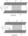
- FIGS. 5A through 5Eillustrate successive steps in an embodiment of a method of the present invention in which the distal end of the apparatus is steered subintimally to create a channel and then steered back into a lumen of a body vessel;
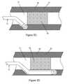
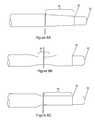
- FIG. 6Ain a side elevation view, illustrates an energy delivery apparatus in accordance with another embodiment of the present invention, the energy delivery apparatus including a radiopaque marker;
- FIG. 6Bin a side cross-sectional view, illustrates the energy delivery apparatus of FIG. 6A ;
- FIG. 6Cin a side elevation view, illustrates an energy delivery apparatus in accordance with yet another embodiment of the present invention, the energy delivery apparatus including a radiopaque marker;
- FIG. 6Din a side cross-sectional view, illustrates the energy delivery apparatus of FIG. 6C ;
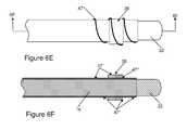
- FIG. 6Ein a side elevation view, illustrates an energy delivery apparatus in accordance with yet another embodiment of the present invention, the energy delivery apparatus including a radiopaque marker;
- FIG. 6Fin a side cross-sectional view, illustrates the energy delivery apparatus of FIG. 6E ;
- FIGS. 7A to 7Din partial perspective views, illustrate energy delivery apparatuses in accordance with various embodiments of the present invention, the energy delivery apparatuses differing from each other by a configuration of their electrodes;
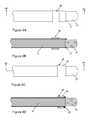
- FIGS. 8A to 8Cin partial side elevational views, illustrate energy delivery apparatuses in accordance with various embodiments of the present invention, the energy delivery apparatuses differing from each other by a configuration of their electrical conductors;
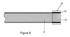
- FIG. 9in a side cross-sectional view, illustrates an energy delivery apparatus in accordance with yet another embodiment of the present invention.
- an energy delivery apparatus 10for delivering electrical energy at a target location.
- the target locationis located inside the body of a patient.
- the energy delivery apparatus 10is usable in combination with a magnetic field (not shown in the drawings).
- the magnetic fieldallows to guide the energy delivery apparatus 10 so that a predetermined component or portion of the energy delivery apparatus, such as for example an electrode, is located substantially adjacent the target location.
- the energy delivery apparatus 10is substantially elongated and defines an apparatus proximal end 12 and a substantially longitudinally opposed apparatus distal end 14 .
- the apparatus proximal end 12is typically configured and sized so as to be couplable to a conventional source of electrical energy.
- the energy delivery apparatus 10includes a substantially elongated electrical conductor 16 , which may be any suitable conductor, such as a wire or a cable made out of a suitable electrically conducting material, such as for example, Nitinol, stainless steel, gold, platinum, titanium, silver or alloys thereof.
- the electrical conductor 16is substantially elongated and defines a conductor proximal end 18 and a substantially longitudinally opposed conductor distal end 20 .
- An electrode 22is electrically coupled to the electrical conductor 16 and located at a predetermined location therealong, for example adjacent to conductor distal end 20 .
- the electrode 22is provided for delivering electrical energy at a target location.
- a guiding element 26is mechanically coupled or otherwise directly or indirectly mounted to the electrical conductor 16 in a substantially spaced apart relationship relative to the electrode 22 .
- the guiding element 26includes a magnetically responsive material.
- the energy delivery apparatus 10is constructed such that movements of the guiding element 26 cause corresponding movements of the electrode 22 .
- the magnetic fieldis therefore usable to move the guiding element 26 in order to position the 22 substantially adjacent to the target location.
- any temperature increase caused by the delivery of electrical energy to the target locationonly minimally influences the magnetic properties of the guiding element 26 .
- some materialssuch as for example permanently magnetized materials, have a temperature over which they lose their magnetic properties.
- this temperatureis sufficiently low that thermal effects caused by the delivery of the electrical energy could contribute significantly to this loss of magnetic properties.
- the guiding element 26is substantially longitudinally spaced apart from the electrode 22 . More specifically, the electrode 22 is located distally relatively to the guiding element 26 . For example, the electrode 22 is located substantially adjacent to the conductor distal end 20 . It should be noted that while the electrode 22 shown in FIG. 2 is substantially cylindrical and extends substantially radially outwardly from the electrical conductor 16 , it is also within the scope of the invention to have an electrode that is formed integrally by a section of the outermost surface of the electrical conductor 16 .
- the electrode 22defines an electrode tip 24 .
- the electrode tip 24defines tip distal surface 25 that is shaped substantially similarly to a portion of a sphere, i.e. rounded. This helps to ensure that injuries that may be caused to the body vessels, through movements of the electrode tip 24 through these vessels, are minimized.
- the energy delivery apparatus 10includes an electrically insulating material substantially covering the electrical conductor 16 , such as for example and non-limitingly, Teflons®, such as polytetrafluoroethylene (PTFE), fluorinated ethylene propylene copolymer (FEP), perfluoroalkoxy (PFA), or ethylene and tetrafluoroethylene copolymer (ETFE, for example Tefzel®), or coatings other than Teflons®, such as polyetheretherketone plastics (PEEKTM), parylene, certain ceramics, or polyethylene terpthalate (PET).
- Teflons®such as polytetrafluoroethylene (PTFE), fluorinated ethylene propylene copolymer (FEP), perfluoroalkoxy (PFA), or ethylene and tetrafluoroethylene copolymer (ETFE, for example Tefzel®
- coatings other than Teflons®such as polyetheretherketone plastics (PEEKTM), parylene,
- the electrically insulating materialforms a layer that extends substantially radially outwardly from the electrical conductor 16 .
- the electrically insulating materialis described in further details hereinbelow.
- at least a portion of the electrode 22is substantially deprived of the electrically insulating material so as to allow delivery of an electrical energy therethrough.
- the energy delivery apparatus 10further includes a heat shield 28 made out of a substantially thermally insulating material, for example, and non-limitingly, polytetrafluoroethylene (PTFE), which has a thermal conductivity of about 0.3 W/m-K.
- the heat shield 28may have a thickness of at least about 0.025 mm. In other embodiments, the thickness of the heat shield 28 may vary, depending on the thermal conductivity of the material being used.
- the heat shield 28is located, at least in part, between the electrode 22 and the guiding element 26 .
- the heat shield 28is provided for further thermally insulating the guiding element 26 from the electrode 22 and from heat produced by the delivery of electrical energy through the electrode 22 .
- the heat shieldincludes polytetrafluoroethylene (PTFE).
- PTFEpolytetrafluoroethylene
- the use of PTFEis advantageous as, in addition to having suitable thermal insulation properties, PTFE is also an electrically insulating material (having a dielectric strength of about 24 kV/mm) and, therefore, contributes to the prevention of arcing between the electrode 22 and any metallic material that may be present in the guiding element 26 .
- other materialssuch as for example, Zirconium Oxide, may be used for heat shield 28 .
- the heat shield 26extends substantially longitudinally from both the guiding element 26 and the electrode 22 .
- the heat shield 28substantially fills a gap between the electrode 22 and the guiding element 26 .
- the heat shield 28extends substantially longitudinally only from one of the guiding element 26 and the electrode 22 or, alternatively, the heat shield 26 does not contact either one of the guiding element 26 and the electrode 22 .
- An advantage of having a heat shield 28 that extends from and contacts both the electrode 22 and the guiding element 26is that the electrodes 22 are then located as close as possible to the guiding element 26 which therefore helps in improving the precision with which the electrode 22 is guided through the magnetic field interacting with the guiding element 26 .
- the guiding element 26 and the heat shield 28are both substantially annular and extend substantially radially outwardly away from the electrically insulating material covering the electrical conductor 16 .
- the electrode 22 , the heat shield 28 and the guiding element 26are all substantially annular and have substantially similar outer diameters. This configuration results in an energy delivery apparatus 10 for which a distal region thereof has a substantially uniform outer diameter, which therefore facilitates navigation of the energy delivery apparatus 10 through body vessels and the creation of channels through occlusions and other biological tissues inside the patient.
- the heat shield 28 , the electrode 22 and the guiding element 26may all have any other suitable diameters.
- the guiding element 26includes one or more guiding components 30 .
- the guiding element 26includes three substantially longitudinally spaced apart guiding components 30 .
- Each of the guiding components 30includes a respective magnetically responsive material.
- having the guiding components 30 spaced apartprovides additional flexibility around guiding element 26 .
- the guiding components 30are substantially adjacent to each other. In such a configuration, having more than one guiding component allows to have a guiding element that is more responsive to a given magnetic field while ensuring that the radial extension of the guiding element 26 is relatively small.
- the guiding components 30are spaced apart further from each other in a manner allowing to control the shape of the electrical conductor 16 .
- the use of three guiding components 30 in the energy delivery apparatus 10has been found to be optimal using commonly available magnetic materials, it is within the scope of the invention to have guiding elements 22 having less than three or more than three guiding components 30 .
- the guiding components 30include permanently magnetized components such as, for example a neodymium magnet, a platinum-cobalt magnet, or any other suitable heat-resistant magnets.
- a heat resistant magnetfor the purpose of this description, is defined as a magnet that has relatively low probabilities of being adversely affected in its magnetization by a delivery of electrical energy through the electrode 22 .
- each of the guiding components 30includes any other suitable magnetically responsive material such as, for example, a ferromagnetic, a paramagnetic, or a diamagnetic material.
- each of the guiding components 30includes a substantially annular magnet 32 coated by a protective coating 33 , such as a parylene coating.
- the protective coating 33ensures biocompatibility between the guiding components 30 and the body in which the energy delivery apparatus 10 is inserted.
- the protective coating 33is any other suitable biocompatible coating.
- an additional coating 39is provided over one or more of the electrode 22 , the heat shield 28 and the guiding components 30 . This additional coating 39 may help to secure components 30 in place, may provide additional lubricity (e.g. it may be hydrophilic) and may be filled with a radiopaque filler for improved visualization.
- the additional coating 39is made of a polyurethane, for example Tecoflex®, Carbothane® or carboflex and it extends between the individual components 30 such that the guiding element 26 has a substantially longitudinally constant outer diameter.
- the electrical conductor 16defines a conductor wider section 34 and a conductor narrower section 36 .
- the conductor narrower section 36is positioned distally relatively to the conductor wider section 34 .
- the conductor wider section 34has a cross-sectional area that is substantially larger than the cross-sectional area of the conductor narrower section 36 .
- the conductor narrower section 36increases the flexibility of the distal end section of the energy delivery apparatus 10 while the conductor wider section 34 allows for maintaining a relatively large rigidity at the proximal end of the energy delivery apparatus 10 . This allows to relatively easily steer the conductor distal end 20 while allowing to relatively easily manipulate the energy delivery apparatus into the body vasculature of the patient.
- having a conductor wider section 34 of a relatively large cross-sectional areareduces ohmic losses when the electrical current is delivered to the electrode 22 .
- the conductor wider and narrower sections 34 and 36are substantially cylindrical and define respective conductor wider and narrower section outer diameters 38 and 40 . Therefore, in these embodiments, the conductor wider section outer diameter is substantially larger than the conductor narrower section outer diameter.
- a conductor narrower section having a conductor narrower section outer diameter of about 0.0025 inches or lesshas been found to be particularly well suited for use in relatively small body vessels.
- the electrical conductor 16is made more flexible substantially adjacent the conductor distal end 20 than substantially adjacent the conductor proximal end 18 in any other suitable manner such as, for example, by using different materials for manufacturing the conductor proximal and distal regions.
- a suitable material for manufacturing the actual conductor 16is Nitinol. Indeed, Nitinol shows super-elastic properties and is therefore particularly suitable for applying relatively large deformations thereto in order to guide the energy delivery apparatus 10 through relatively tortuous paths. Also, since the energy delivery apparatus 10 typically creates channels inside biological tissues through radio frequency perforations, in some embodiments of the invention, the energy delivery apparatus 10 typically does not need to be very rigid.
- the electrically insulating materialis divided into a first electrically insulating material and a second electrically insulating material.
- a first electrically insulating layer 42 made out of the first electrically insulating materialsubstantially covers a first section of the electrical conductor 16 .
- a second electrically insulating layer 44 made out of the second electrically insulating materialsubstantially covers a second section of the electrical conductor 16 .
- the second sectionis located distally relatively to the first section.
- the first and second electrically insulating materialsmay comprise different materials with differing physical properties.
- the second electrically insulating materialcomprises polyimide
- the first electrically insulating materialcomprises PTFE.
- the second electrically insulating layer 44allows for the second electrically insulating layer 44 to be substantially thinner than the first electrically insulating layer 42 , while being sufficiently insulative so as to prevent undesired leakage of current.
- Thissubstantially increases the flexibility of the energy delivery apparatus 10 substantially adjacent the apparatus distal end 14 .
- thisprovides a material that is substantially more lubricious over the wider section of the energy delivery apparatus 10 so as to facilitate movement of the energy delivery apparatus 10 through body vessels and through channels created within the body.
- the first electrically insulating layer 42substantially covers the conductor wider section 34 and the second electrically insulating layer 44 substantially covers the conductor narrower section 36 .
- the first and second electrically insulating layers 42 and 44are configured in any other suitable manner.
- the first electrically insulating layer 42substantially overlaps the second electrically insulating layer 44 at their junction.
- the electrical conductor 16is electrically insulated in any other suitable manner.
- a radiopaque markeris mounted to the electrical conductor 16 .
- the radiopaque markeris also the magnetically responsive material present in the guiding elements 26 .
- the radiopaque markerincludes a radiopaque material that is distinct from the guiding element 26 and that is secured to conductor 16 or secured or embedded into the electrically insulating layer, among other possibilities. For example, FIGS.
- FIGS. 6A to 6Frespectively illustrate embodiments of the invention wherein a radiopaque band 47 is mounted around the electrode 22 , at the proximal-most portion of the electrode 22 , a radiopaque band 47 ′ is mounted under the heat shield 28 and a radiopaque coil 47 ′′ is wrapped around the distalmost portion of the energy delivery apparatus 10 .
- FIG. 3in a flowchart, illustrates a method 100 for delivering electrical energy at the target location using the energy delivery apparatus 10 and a magnetic field.
- FIGS. 4A to 4D and 5 A to 5 Eillustrate specific examples of implementation of the method 100 .
- the target locationis located in the body of a patient.
- the bodyincludes a body vessel 46 , 46 ′ defining a lumen 51 , 51 ′ and the energy delivery apparatus may be the energy delivery apparatus 10 or any other suitable energy delivery apparatus.
- the methodstarts at step 105 .
- the apparatus distal end 14is inserted into the body vessel 46 , 46 ′.
- the magnetic fieldis applied to exert a magnetic force onto the magnetically responsive material so as to move the electrode 22 at step 115 .
- the electrode 22is guided to an electrode location, the electrode location being substantially adjacent to the target location.
- the electrical energyis delivered at the target location through the electrode 22 and the method ends at step 130 .
- delivering the electrical energy and applying the magnetic fieldare performed substantially simultaneously. Such embodiments allow for guiding the electrode while a channel or perforation is created, for example. In other words, as shown for example in FIG. 5 , applying the magnetic field while delivering energy allows for greater control over the creation of the channel or perforation at the target location.
- the delivery of energy and the application of the magnet fieldoccur partially concurrently while, in further embodiments, the delivery of energy and the application of the magnetic field occur at substantially different points in time, for example substantially sequentially.
- advancing the apparatus through the body and applying the magnetic fieldare performed substantially simultaneously.
- advancing the apparatus and the application of the magnet fieldoccur partially concurrently while, in further embodiments, advancing the apparatus and the application of the magnetic field occur at substantially different points in time, for example substantially sequentially.
- the magnetic fieldis applied when the apparatus distal end is advanced through the body vessel 46 , 46 ′ and arrives at a bifurcation in the body vessel 46 , 46 ′. Then, the magnetic field may be applied to select which branch of the body vessel 46 , 46 ′ will be entered by the apparatus distal end 14 , and the apparatus distal end 14 is then further advanced through the body vessel 46 , 46 ′ to enter the selected branch. In these embodiments, the apparatus distal end 14 is advanced into the body vessel 46 , 46 ′ while substantially simultaneously applying the magnetic field.
- the target locationis included in an occlusion 50 , the occlusion 50 at least partially occluding the body vessel 46 , 46 ′.
- body vessels 46 , 46 ′that are typically not accessible using conventional energy delivery apparatuses, such as coronary blood vessels, peripheral blood vessels and cranial blood vessels, among other possibilities, are relatively easily accessible using the energy delivery apparatus 10 . Therefore, the presence of the electrode 22 and of the guiding element 26 in the energy delivery apparatus 10 produce a synergistic effect allowing to perform surgical procedures that were typically not able to be performed using prior art energy delivery apparatuses.
- the energy delivery apparatus 10is used such that a channel 52 is created at least partially through the occlusion.
- This channelmay be created by delivering energy through the electrode 22 and advancing the apparatus distal end into the occlusion 50 simultaneously or after delivering energy.
- advancing the apparatus distal end and applying the magnetic fieldare performed substantially simultaneously.
- the shape of a channel 52 created inside the body vessel 46may therefore be controlled through the application of a magnetic field.
- the application of the magnetic fieldallows to relatively easily control the position of the electrode 22 such that the apparatus distal end may be advanced through a section of a vessel wall 54 of the body vessel 46 ′ (as seen in FIGS. 5C and 5D ). Afterwards, reversing the orientation of the magnetic field allows to advance the apparatus distal end 14 back into the lumen 51 ′ of the body vessel 46 ′ (as seen in FIG. 5E ).
- This methodis particularly advantageous in cases wherein the occlusion present in the body vessel has properties making it relatively difficult to penetrate using the energy delivery apparatus 10 .
- a channelmay be created completely through the vessel wall, such that the energy delivery apparatus exits the vessel wall. For example, this may be useful in applications where it is desired to provide a connection between two vessels.
- the intended user of the energy delivery apparatus 10when the intended user of the energy delivery apparatus 10 finds that advancing through the occlusion 50 or any other material becomes relatively difficult, the intended user may retract the apparatus distal end and apply electrical energy while a gap exists between the apparatus distal end and the target location. Then, a channel may be created more easily, for example due to the space created between the electrode 22 and the occlusion 50 . Afterwards, the apparatus distal end may then be further advanced through this channel.
- the claimed energy delivery apparatusis particularly well suited for creating channels in occlusions that are located at a bifurcation in the body vessel. Indeed, in prior art devices, the presence of the occlusion at the bifurcation typically pushes the apparatus distal end 14 of prior art devices through the non-occluded branch of the body vessel, which therefore makes the creation of channels through the occlusion relatively difficult.
- the apparatus distal endmay be oriented such that the electrode 22 remains substantially adjacent to the occlusion until at least a portion of a channel is created into the occlusion which allows the distal end of the energy delivery apparatus to be received within the occlusion, such that the energy delivery apparatus is guided away from the non-occluded branch.
- the body vesselis an airway present in a lung including lung tissue defining airways.
- the electrode 22By suitably positioning the electrode 22 , it is possible to deliver the electrical energy to create an air pathway extending from the airway into the lung tissue.
- the electrical conductor 16is between about 40 centimeters and about 350 centimeters in length. In more specific embodiments of the invention, the electrical conductor 16 is between about 65 centimeters and 265 centimeters in length.
- the outer diameter of the energy delivery apparatus 10is typically between about 0.01 inches and about 0.05 inches. In a specific embodiment of the invention, the outer diameter is between about 0.014 inches and about 0.04 inches. In a very specific embodiment of the invention, the electrical conductor 16 has an outer diameter of about 0.0025 inches in the narrower section and 0.012 inches in the wider section.
- the electrodeis typically less than about 4 millimeters in length.
- Typical values from the thickness of the electrically insulating materialsvary from about 0.015 inches to about 0.05 inches. However, other values are within the scope of the invention. In a specific embodiment of the invention, the thickness of the PTFE is about 0.03 inches.
- the heat shield 28may be between about 0.05 cm and about 0.20 cm in length, and between 0.025 and about 0.05 cm in thickness.
- the heat shield materialis about 0.1 cm in length, and about 0.035 cm in thickness.
- the conductor narrower section 36may be located substantially adjacent the conductor distal end 20 .
- the conductor narrower section 36is located substantially spaced apart from the conductor distal end 20 .
- the conductor narrower section 36may have a substantially uniform diameter or, as shown in FIG. 8A , may have a substantially tapering outer diameter, the outer diameter tapering in a direction, for example, leading towards the conductor distal end 20 .
- the magnetically responsive materialis welded, soldered, adhered or otherwise attached to the conductor distal end 20 .
- the guiding element 26 ′is substantially radially spaced apart from the electrode 22 ′, the heat shield 28 ′ extending therebetween.
- the electrode 22 a , 22 b , 22 c and 22 dmay take the form of a distal surface of the electrical conductor 16 that is deprived of insulating material, a cylindrical section of the electrical conductor 16 that is deprived of insulating material, an electrically conductive component, for example a stainless steel cylinder, which is electrically coupled to conductor 16 , or a combination of a conductive component and a section of the conductor 16 .
- an auxiliary devicemay be advanced to the target location by using the energy delivery apparatus 10 as a guide or a rail.
- the apparatus proximal endmay be passed through the auxiliary device, and the auxiliary device may then be advanced together with energy delivery apparatus 10 into the patient's body.
- the auxiliary devicemay be inserted over energy delivery apparatus 10 and into the patient's body after energy delivery apparatus 10 has reached the target location.
- auxiliary devicesinclude, but are not limited to, catheters, sheaths, dilators, visualization devices, or any other devices having a lumen within which energy delivery apparatus 10 may be disposed.
- the energy delivery apparatus 10may comprise means for enhancing steerability.
- Such meansmay include piezo-actuators or electroactive polymers disposed on the distal region of the energy delivery apparatus 10 .
- a piezo-actuator or electroactive polymermay be disposed on one side of the energy delivery apparatus 10 , such that when an electrical field is applied across the piezo-actuator or electroactive polymer, a strain is generated along one side of the energy delivery apparatus 10 , causing the energy delivery apparatus 10 to deflect in a desired direction.
Landscapes
- Health & Medical Sciences (AREA)
- Life Sciences & Earth Sciences (AREA)
- Engineering & Computer Science (AREA)
- Surgery (AREA)
- Veterinary Medicine (AREA)
- Public Health (AREA)
- General Health & Medical Sciences (AREA)
- Biomedical Technology (AREA)
- Heart & Thoracic Surgery (AREA)
- Animal Behavior & Ethology (AREA)
- Nuclear Medicine, Radiotherapy & Molecular Imaging (AREA)
- Medical Informatics (AREA)
- Molecular Biology (AREA)
- Physics & Mathematics (AREA)
- Cardiology (AREA)
- Plasma & Fusion (AREA)
- Biophysics (AREA)
- Pathology (AREA)
- Human Computer Interaction (AREA)
- Otolaryngology (AREA)
- Robotics (AREA)
- Radiology & Medical Imaging (AREA)
- Surgical Instruments (AREA)
- Media Introduction/Drainage Providing Device (AREA)
- Crystals, And After-Treatments Of Crystals (AREA)
Abstract
Description
Claims (15)
Priority Applications (6)
| Application Number | Priority Date | Filing Date | Title |
|---|---|---|---|
| US11/627,406US8092450B2 (en) | 2003-01-21 | 2007-01-26 | Magnetically guidable energy delivery apparatus and method of using same |
| PCT/US2007/061203WO2007090075A2 (en) | 2006-01-27 | 2007-01-29 | Magnetically guidable energy delivery apparatus and method of using same |
| US12/926,292US9510900B2 (en) | 2003-01-21 | 2010-11-08 | Electrosurgical device for creating a channel through a region of tissue and methods of use thereof |
| US14/049,449US20140039484A1 (en) | 2003-09-19 | 2013-10-09 | Methods for creating a channel through an occlusion within a body vessel |
| US15/359,881US11234761B2 (en) | 2006-01-27 | 2016-11-23 | Electrosurgical device for creating a channel through a region of tissue and methods of use thereof |
| US17/574,815US20220151681A1 (en) | 2006-01-27 | 2022-01-13 | Electrosurgical Device for Creating a Channel through a Region of Tissue and Methods of Use thereof |
Applications Claiming Priority (10)
| Application Number | Priority Date | Filing Date | Title |
|---|---|---|---|
| US10/347,366US7112197B2 (en) | 2003-01-21 | 2003-01-21 | Surgical device with pressure monitoring ability |
| US10/666,288US20040143262A1 (en) | 2003-01-21 | 2003-09-19 | Surgical perforation device and method with pressure monitoring and staining abilities |
| US10/666,301US7048733B2 (en) | 2003-09-19 | 2003-09-19 | Surgical perforation device with curve |
| US10/760,479US7270662B2 (en) | 2004-01-21 | 2004-01-21 | Surgical perforation device with electrocardiogram (ECG) monitoring ability and method of using ECG to position a surgical perforation device |
| US59629705P | 2005-09-14 | 2005-09-14 | |
| US11/265,304US7947040B2 (en) | 2003-01-21 | 2005-11-03 | Method of surgical perforation via the delivery of energy |
| US74318106P | 2006-01-27 | 2006-01-27 | |
| US11/520,754US7828796B2 (en) | 2003-01-21 | 2006-09-14 | Method for creating a channel through an occlusion and apparatus therefor |
| US82745806P | 2006-09-29 | 2006-09-29 | |
| US11/627,406US8092450B2 (en) | 2003-01-21 | 2007-01-26 | Magnetically guidable energy delivery apparatus and method of using same |
Related Parent Applications (2)
| Application Number | Title | Priority Date | Filing Date |
|---|---|---|---|
| US11/520,754Continuation-In-PartUS7828796B2 (en) | 2003-01-21 | 2006-09-14 | Method for creating a channel through an occlusion and apparatus therefor |
| US13/410,868Continuation-In-PartUS9168085B2 (en) | 2003-09-19 | 2012-03-02 | Monitoring and controlling energy delivery of an electrosurgical device |
Related Child Applications (3)
| Application Number | Title | Priority Date | Filing Date |
|---|---|---|---|
| US10/347,366Continuation-In-PartUS7112197B2 (en) | 2003-01-21 | 2003-01-21 | Surgical device with pressure monitoring ability |
| US12/923,292Continuation-In-PartUS8794629B1 (en) | 2003-09-19 | 2010-09-14 | Method and apparatus for poker bag toss game |
| US12/926,292Continuation-In-PartUS9510900B2 (en) | 2003-01-21 | 2010-11-08 | Electrosurgical device for creating a channel through a region of tissue and methods of use thereof |
Publications (2)
| Publication Number | Publication Date |
|---|---|
| US20070123964A1 US20070123964A1 (en) | 2007-05-31 |
| US8092450B2true US8092450B2 (en) | 2012-01-10 |
Family
ID=38349473
Family Applications (1)
| Application Number | Title | Priority Date | Filing Date |
|---|---|---|---|
| US11/627,406Active2030-10-09US8092450B2 (en) | 2003-01-21 | 2007-01-26 | Magnetically guidable energy delivery apparatus and method of using same |
Country Status (2)
| Country | Link |
|---|---|
| US (1) | US8092450B2 (en) |
| WO (1) | WO2007090075A2 (en) |
Cited By (10)
| Publication number | Priority date | Publication date | Assignee | Title |
|---|---|---|---|---|
| US8308628B2 (en) | 2009-11-02 | 2012-11-13 | Pulse Therapeutics, Inc. | Magnetic-based systems for treating occluded vessels |
| US9883878B2 (en) | 2012-05-15 | 2018-02-06 | Pulse Therapeutics, Inc. | Magnetic-based systems and methods for manipulation of magnetic particles |
| US11583312B2 (en) | 2020-08-25 | 2023-02-21 | Cross Vascular, Inc. | Transseptal crossing system |
| US11648047B2 (en) | 2017-10-06 | 2023-05-16 | Vive Scientific, Llc | System and method to treat obstructive sleep apnea |
| US11918315B2 (en) | 2018-05-03 | 2024-03-05 | Pulse Therapeutics, Inc. | Determination of structure and traversal of occlusions using magnetic particles |
| US11957848B2 (en) | 2019-04-18 | 2024-04-16 | UNandUP, LLC | Magnetically controlled medical devices for interventional medical procedures and methods of making and controlling the same |
| US12016619B2 (en) | 2020-05-14 | 2024-06-25 | Circa Scientific, Inc. | Transseptal crossing system for single pass large bore access |
| US12070560B2 (en) | 2019-04-18 | 2024-08-27 | UNandUP, LLC | Magnetically controlled linkage based devices |
| US12171443B1 (en) | 2021-03-09 | 2024-12-24 | Pulse Therapeutics, Inc. | Magnetically controlled flow generation |
| US12433639B2 (en) | 2013-08-07 | 2025-10-07 | Boston Scientific Medical Device Limited | Methods and devices for puncturing tissue |
Families Citing this family (57)
| Publication number | Priority date | Publication date | Assignee | Title |
|---|---|---|---|---|
| US9510900B2 (en)* | 2003-01-21 | 2016-12-06 | Baylis Medical Company Inc. | Electrosurgical device for creating a channel through a region of tissue and methods of use thereof |
| WO2006069257A2 (en) | 2004-12-20 | 2006-06-29 | Stereotaxis, Inc. | Contact over torque with three dimensional anatomical data |
| US7756308B2 (en) | 2005-02-07 | 2010-07-13 | Stereotaxis, Inc. | Registration of three dimensional image data to 2D-image-derived data |
| US9314222B2 (en) | 2005-07-07 | 2016-04-19 | Stereotaxis, Inc. | Operation of a remote medical navigation system using ultrasound image |
| US7495537B2 (en) | 2005-08-10 | 2009-02-24 | Stereotaxis, Inc. | Method and apparatus for dynamic magnetic field control using multiple magnets |
| US20220151681A1 (en)* | 2006-01-27 | 2022-05-19 | Baylis Medical Company Inc. | Electrosurgical Device for Creating a Channel through a Region of Tissue and Methods of Use thereof |
| US12161390B2 (en) | 2006-09-29 | 2024-12-10 | Boston Scientific Medical Device Limited | Connector system for electrosurgical device |
| US11666377B2 (en) | 2006-09-29 | 2023-06-06 | Boston Scientific Medical Device Limited | Electrosurgical device |
| US8024024B2 (en) | 2007-06-27 | 2011-09-20 | Stereotaxis, Inc. | Remote control of medical devices using real time location data |
| US8394091B2 (en)* | 2007-08-24 | 2013-03-12 | Boston Scientific Scimed, Inc. | Magnetically steerable catheter assembly |
| US8231618B2 (en) | 2007-11-05 | 2012-07-31 | Stereotaxis, Inc. | Magnetically guided energy delivery apparatus |
| US20090131798A1 (en)* | 2007-11-19 | 2009-05-21 | Minar Christopher D | Method and apparatus for intravascular imaging and occlusion crossing |
| JP5444860B2 (en)* | 2008-06-24 | 2014-03-19 | 三菱マテリアル株式会社 | Polycrystalline silicon production equipment |
| US10537713B2 (en) | 2009-05-25 | 2020-01-21 | Stereotaxis, Inc. | Remote manipulator device |
| EP3556308B1 (en) | 2009-11-05 | 2023-12-20 | Stratus Medical, LLC | Systems for spinal radio frequency neurotomy |
| KR101632429B1 (en) | 2010-05-21 | 2016-06-21 | 님버스 컨셉츠, 엘엘씨 | Systems and methods for tissue ablation |
| US10792096B2 (en) | 2010-11-08 | 2020-10-06 | Baylis Medical Company Inc. | Medical device having a support structure |
| US10258791B2 (en)* | 2012-04-27 | 2019-04-16 | Medtronic Ardian Luxembourg S.A.R.L. | Catheter assemblies for neuromodulation proximate a bifurcation of a renal artery and associated systems and methods |
| EP4599879A2 (en) | 2012-05-31 | 2025-08-13 | Boston Scientific Medical Device Limited | Radiofrequency perforation apparatus |
| EP2968846B1 (en)* | 2013-03-12 | 2022-05-04 | Baylis Medical Company Inc. | Medical device having a support structure |
| US11937873B2 (en) | 2013-03-12 | 2024-03-26 | Boston Scientific Medical Device Limited | Electrosurgical device having a lumen |
| JP6462600B2 (en)* | 2013-03-14 | 2019-01-30 | ベイリス メディカル カンパニー インコーポレイテッドBaylis Medical Company Inc. | Electrosurgical device having a lumen |
| CA3220441A1 (en) | 2013-03-15 | 2015-09-17 | Boston Scientific Medical Device Limited | Electrosurgical device having a distal aperture |
| WO2014150603A1 (en)* | 2013-03-15 | 2014-09-25 | Sri Radhakrishnan | Systems and methods for treatment using magnetic fields |
| US10661057B2 (en) | 2013-12-20 | 2020-05-26 | Baylis Medical Company Inc. | Steerable medical device handle |
| US20150174371A1 (en)* | 2013-12-23 | 2015-06-25 | Cook Medical Technologies Llc | System for bypassing vascular occlusion having puncturing mechanism and method |
| AU2016319002B2 (en) | 2015-09-09 | 2021-05-13 | Boston Scientific Medical Device Limited | Epicardial access system & methods |
| WO2017069940A1 (en)* | 2015-10-20 | 2017-04-27 | Spiration, Inc., d.b.a. Olympus Respiratory America | Ablation device |
| WO2017118948A1 (en) | 2016-01-07 | 2017-07-13 | Baylis Medical Company Inc. | Hybrid transseptal dilator and methods of using the same |
| CN110114027B (en) | 2016-11-01 | 2022-09-06 | 贝利斯医疗公司 | Method and apparatus for puncturing tissue |
| BR112020011128A2 (en) | 2017-08-10 | 2021-05-04 | Baylis Medical Company Inc. | heat exchange device and temperature sensor and method of use |
| EP3579909B1 (en) | 2017-12-05 | 2020-09-09 | Pedersen, Wesley Robert | Transseptal guide wire puncture system |
| CN112272574A (en) | 2018-05-08 | 2021-01-26 | 贝利斯医疗公司 | Coupling mechanism for device |
| KR20220021468A (en) | 2019-04-29 | 2022-02-22 | 베이리스 메디컬 컴퍼니 아이엔씨. | Transseptal system, device and method |
| US11759190B2 (en) | 2019-10-18 | 2023-09-19 | Boston Scientific Medical Device Limited | Lock for medical devices, and related systems and methods |
| US11801087B2 (en) | 2019-11-13 | 2023-10-31 | Boston Scientific Medical Device Limited | Apparatus and methods for puncturing tissue |
| US11724070B2 (en) | 2019-12-19 | 2023-08-15 | Boston Scientific Medical Device Limited | Methods for determining a position of a first medical device with respect to a second medical device, and related systems and medical devices |
| US11931098B2 (en) | 2020-02-19 | 2024-03-19 | Boston Scientific Medical Device Limited | System and method for carrying out a medical procedure |
| US12082792B2 (en) | 2020-02-25 | 2024-09-10 | Boston Scientific Medical Device Limited | Systems and methods for creating a puncture between aorta and the left atrium |
| US11986209B2 (en) | 2020-02-25 | 2024-05-21 | Boston Scientific Medical Device Limited | Methods and devices for creation of communication between aorta and left atrium |
| US11819243B2 (en) | 2020-03-19 | 2023-11-21 | Boston Scientific Medical Device Limited | Medical sheath and related systems and methods |
| US11826075B2 (en) | 2020-04-07 | 2023-11-28 | Boston Scientific Medical Device Limited | Elongated medical assembly |
| US12011279B2 (en) | 2020-04-07 | 2024-06-18 | Boston Scientific Medical Device Limited | Electro-anatomic mapping system |
| US12420067B2 (en) | 2020-05-12 | 2025-09-23 | Boston Scientific Medical Device Limited | Guidewire assembly |
| US11938285B2 (en) | 2020-06-17 | 2024-03-26 | Boston Scientific Medical Device Limited | Stop-movement device for elongated medical assembly |
| CN116437857A (en) | 2020-06-17 | 2023-07-14 | 波士顿科学医疗设备有限公司 | Electroanatomical mapping system |
| US11937796B2 (en) | 2020-06-18 | 2024-03-26 | Boston Scientific Medical Device Limited | Tissue-spreader assembly |
| US12343042B2 (en) | 2020-07-16 | 2025-07-01 | Boston Scientific Medical Device Limited | Pericardial puncture device and method |
| US20230310107A1 (en)* | 2020-07-16 | 2023-10-05 | Covidien Lp | Magnetically attachable tissue clips for use in endoscopic submucosal dissection |
| US12042178B2 (en) | 2020-07-21 | 2024-07-23 | Boston Scientific Medical Device Limited | System of medical devices and method for pericardial puncture |
| US12005202B2 (en) | 2020-08-07 | 2024-06-11 | Boston Scientific Medical Device Limited | Catheter having tissue-engaging device |
| US12396785B2 (en) | 2020-08-12 | 2025-08-26 | Boston Scientific Medical Device Limited | System of medical devices and method for pericardial puncture |
| CA3128527A1 (en) | 2020-09-10 | 2022-03-10 | Baylis Medical Company Inc. | Elongated medical catheter including marker band |
| US11980412B2 (en) | 2020-09-15 | 2024-05-14 | Boston Scientific Medical Device Limited | Elongated medical sheath |
| MX2023014102A (en)* | 2021-05-27 | 2023-12-11 | Becton Dickinson Co | METHOD OF RELOCATION OF A DISTAL CATHETER TIP AND RELATED SYSTEMS. |
| CN114983376B (en)* | 2022-03-30 | 2025-05-09 | 杭州阿特瑞科技有限公司 | A coronary artery FFR measurement system based on blood flow velocity monitoring device |
| WO2024188679A1 (en)* | 2023-03-13 | 2024-09-19 | Koninklijke Philips N.V. | Articulation of a chronic total occlusion (cto) crossing device to an optimal entry point |
Citations (54)
| Publication number | Priority date | Publication date | Assignee | Title |
|---|---|---|---|---|
| US4244362A (en) | 1978-11-29 | 1981-01-13 | Anderson Charles C | Endotracheal tube control device |
| US4790809A (en) | 1985-08-29 | 1988-12-13 | Medical Engineering Corporation | Ureteral stent |
| US4790311A (en) | 1986-06-03 | 1988-12-13 | Ruiz Oscar F | Radio frequency angioplasty catheter system |
| US4807620A (en) | 1987-05-22 | 1989-02-28 | Advanced Interventional Systems, Inc. | Apparatus for thermal angioplasty |
| US5019076A (en) | 1986-09-12 | 1991-05-28 | Yamanashi William S | Radio frequency surgical tool and method |
| US5318525A (en) | 1992-04-10 | 1994-06-07 | Medtronic Cardiorhythm | Steerable electrode catheter |
| US5364393A (en) | 1990-07-02 | 1994-11-15 | Heart Technology, Inc. | Tissue dissipative recanalization catheter |
| US5397304A (en) | 1992-04-10 | 1995-03-14 | Medtronic Cardiorhythm | Shapable handle for steerable electrode catheter |
| US5425382A (en) | 1993-09-14 | 1995-06-20 | University Of Washington | Apparatus and method for locating a medical tube in the body of a patient |
| US5624430A (en) | 1994-11-28 | 1997-04-29 | Eton; Darwin | Magnetic device to assist transcorporeal guidewire placement |
| US5779688A (en)* | 1994-10-28 | 1998-07-14 | Intella Interventional Systems, Inc. | Low profile balloon-on-a-wire catheter with shapeable and/or deflectable tip and method |
| US5885227A (en) | 1997-03-25 | 1999-03-23 | Radius Medical Technologies, Inc. | Flexible guidewire with radiopaque plastic tip |
| US5916210A (en) | 1990-01-26 | 1999-06-29 | Intraluminal Therapeutics, Inc. | Catheter for laser treatment of atherosclerotic plaque and other tissue abnormalities |
| US5931818A (en) | 1997-08-29 | 1999-08-03 | Stereotaxis, Inc. | Method of and apparatus for intraparenchymal positioning of medical devices |
| US5944023A (en) | 1995-12-07 | 1999-08-31 | Sims Deltec, Inc. | Systems and methods for determining the location of an implanted device including a magnet |
| US5951482A (en) | 1997-10-03 | 1999-09-14 | Intraluminal Therapeutics, Inc. | Assemblies and methods for advancing a guide wire through body tissue |
| US5964757A (en)* | 1997-09-05 | 1999-10-12 | Cordis Webster, Inc. | Steerable direct myocardial revascularization catheter |
| US5989276A (en)* | 1996-11-08 | 1999-11-23 | Advanced Bypass Technologies, Inc. | Percutaneous bypass graft and securing system |
| US6013072A (en) | 1997-07-09 | 2000-01-11 | Intraluminal Therapeutics, Inc. | Systems and methods for steering a catheter through body tissue |
| US6048349A (en) | 1997-07-09 | 2000-04-11 | Intraluminal Therapeutics, Inc. | Systems and methods for guiding a medical instrument through a body |
| WO2000019917A1 (en) | 1998-10-02 | 2000-04-13 | Stereotaxis, Inc. | Magnetically navigable and/or controllable device for removing material from body lumens and cavities |
| US6106515A (en) | 1998-08-13 | 2000-08-22 | Intraluminal Therapeutics, Inc. | Expandable laser catheter |
| US6155264A (en) | 1997-03-06 | 2000-12-05 | Scimed Life Systems, Inc. | Percutaneous bypass by tunneling through vessel wall |
| US6193676B1 (en) | 1997-10-03 | 2001-02-27 | Intraluminal Therapeutics, Inc. | Guide wire assembly |
| WO2001017600A1 (en) | 1999-09-10 | 2001-03-15 | Stereotaxis, Inc. | Variable stiffness magnetic catheter |
| US6210408B1 (en) | 1999-02-24 | 2001-04-03 | Scimed Life Systems, Inc. | Guide wire system for RF recanalization of vascular blockages |
| US6221061B1 (en) | 1993-05-12 | 2001-04-24 | Target Therapeutics, Inc. | Lubricious catheters |
| US6228076B1 (en) | 1999-01-09 | 2001-05-08 | Intraluminal Therapeutics, Inc. | System and method for controlling tissue ablation |
| US6292678B1 (en) | 1999-05-13 | 2001-09-18 | Stereotaxis, Inc. | Method of magnetically navigating medical devices with magnetic fields and gradients, and medical devices adapted therefor |
| US6304769B1 (en) | 1997-10-16 | 2001-10-16 | The Regents Of The University Of California | Magnetically directable remote guidance systems, and methods of use thereof |
| WO2001093939A1 (en) | 2000-06-02 | 2001-12-13 | Scimed Life Systems, Inc. | Magnetic guide wire and catheter |
| US20020019644A1 (en)* | 1999-07-12 | 2002-02-14 | Hastings Roger N. | Magnetically guided atherectomy |
| US6385472B1 (en) | 1999-09-10 | 2002-05-07 | Stereotaxis, Inc. | Magnetically navigable telescoping catheter and method of navigating telescoping catheter |
| US6394976B1 (en) | 2000-01-31 | 2002-05-28 | Intraluminal Therapeutics, Inc. | Catheter for controlling the advancement of a guide wire |
| US6428551B1 (en) | 1999-03-30 | 2002-08-06 | Stereotaxis, Inc. | Magnetically navigable and/or controllable device for removing material from body lumens and cavities |
| US6508754B1 (en) | 1997-09-23 | 2003-01-21 | Interventional Therapies | Source wire for radiation treatment |
| US6524303B1 (en) | 2000-09-08 | 2003-02-25 | Stereotaxis, Inc. | Variable stiffness magnetic catheter |
| US6554827B2 (en) | 2000-12-11 | 2003-04-29 | Scimed Life Systems, Inc. | Radio frequency ablation system |
| US6662034B2 (en) | 2000-11-15 | 2003-12-09 | Stereotaxis, Inc. | Magnetically guidable electrophysiology catheter |
| US6709444B1 (en) | 1996-02-02 | 2004-03-23 | Transvascular, Inc. | Methods for bypassing total or near-total obstructions in arteries or other anatomical conduits |
| US20040116851A1 (en) | 2002-12-16 | 2004-06-17 | Intraluminal Therapeutics, Inc. | Deflecting catheter |
| US6752800B1 (en) | 2000-02-18 | 2004-06-22 | Intraluminal Therapeutics Inc. | Catheter handle for controlling the advancement of a guide wire |
| US6755816B2 (en) | 1999-10-04 | 2004-06-29 | Stereotaxis, Inc. | Method for safely and efficiently navigating magnetic devices in the body |
| US20040133130A1 (en) | 2003-01-06 | 2004-07-08 | Ferry Steven J. | Magnetically navigable medical guidewire |
| US6820614B2 (en) | 2000-12-02 | 2004-11-23 | The Bonutti 2003 Trust -A | Tracheal intubination |
| US6834201B2 (en)* | 2001-01-29 | 2004-12-21 | Stereotaxis, Inc. | Catheter navigation within an MR imaging device |
| US6842639B1 (en) | 1997-10-03 | 2005-01-11 | Intraluminal Therapeutics, Inc. | Method and apparatus for determining neovascular flow through tissue in a vessel |
| US20050010208A1 (en) | 2002-06-11 | 2005-01-13 | Winston Thomas R. | Radio frequency guide wire assembly with optical coherence reflectometry guidance |
| US6855143B2 (en) | 1997-06-13 | 2005-02-15 | Arthrocare Corporation | Electrosurgical systems and methods for recanalization of occluded body lumens |
| US20050096529A1 (en)* | 1999-08-05 | 2005-05-05 | Broncus Technologies, Inc. | Methods for treating chronic obstructive pulmonary disease |
| US20050261607A1 (en) | 2003-04-10 | 2005-11-24 | Intraluminal Therapeutics, Inc. | Shapeable intraluminal device and method therefor |
| US6980843B2 (en) | 2003-05-21 | 2005-12-27 | Stereotaxis, Inc. | Electrophysiology catheter |
| US20050288631A1 (en)* | 1998-02-03 | 2005-12-29 | Lewis Brian D | Methods and systems for treating ischemia |
| US20060089638A1 (en) | 2004-10-27 | 2006-04-27 | Yuval Carmel | Radio-frequency device for passivation of vascular plaque and method of using same |
Family Cites Families (2)
| Publication number | Priority date | Publication date | Assignee | Title |
|---|---|---|---|---|
| US5444827A (en)* | 1994-05-23 | 1995-08-22 | Hewlett-Packard Company | Method and apparatus for preventing print overruns by rasterizing complex page strips using an increased clock frequency |
| US6795573B2 (en)* | 2000-01-27 | 2004-09-21 | Nikon Corporation | Inspection method and apparatus |
- 2007
- 2007-01-26USUS11/627,406patent/US8092450B2/enactiveActive
- 2007-01-29WOPCT/US2007/061203patent/WO2007090075A2/enactiveApplication Filing
Patent Citations (67)
| Publication number | Priority date | Publication date | Assignee | Title |
|---|---|---|---|---|
| US4244362A (en) | 1978-11-29 | 1981-01-13 | Anderson Charles C | Endotracheal tube control device |
| US4790809A (en) | 1985-08-29 | 1988-12-13 | Medical Engineering Corporation | Ureteral stent |
| US4790311A (en) | 1986-06-03 | 1988-12-13 | Ruiz Oscar F | Radio frequency angioplasty catheter system |
| US5019076A (en) | 1986-09-12 | 1991-05-28 | Yamanashi William S | Radio frequency surgical tool and method |
| US4807620A (en) | 1987-05-22 | 1989-02-28 | Advanced Interventional Systems, Inc. | Apparatus for thermal angioplasty |
| US5916210A (en) | 1990-01-26 | 1999-06-29 | Intraluminal Therapeutics, Inc. | Catheter for laser treatment of atherosclerotic plaque and other tissue abnormalities |
| US5364393A (en) | 1990-07-02 | 1994-11-15 | Heart Technology, Inc. | Tissue dissipative recanalization catheter |
| US5397304A (en) | 1992-04-10 | 1995-03-14 | Medtronic Cardiorhythm | Shapable handle for steerable electrode catheter |
| US5318525A (en) | 1992-04-10 | 1994-06-07 | Medtronic Cardiorhythm | Steerable electrode catheter |
| US6221061B1 (en) | 1993-05-12 | 2001-04-24 | Target Therapeutics, Inc. | Lubricious catheters |
| US5425382A (en) | 1993-09-14 | 1995-06-20 | University Of Washington | Apparatus and method for locating a medical tube in the body of a patient |
| US5622169A (en) | 1993-09-14 | 1997-04-22 | University Of Washington | Apparatus and method for locating a medical tube in the body of a patient |
| US5779688A (en)* | 1994-10-28 | 1998-07-14 | Intella Interventional Systems, Inc. | Low profile balloon-on-a-wire catheter with shapeable and/or deflectable tip and method |
| US5624430A (en) | 1994-11-28 | 1997-04-29 | Eton; Darwin | Magnetic device to assist transcorporeal guidewire placement |
| US5944023A (en) | 1995-12-07 | 1999-08-31 | Sims Deltec, Inc. | Systems and methods for determining the location of an implanted device including a magnet |
| US6709444B1 (en) | 1996-02-02 | 2004-03-23 | Transvascular, Inc. | Methods for bypassing total or near-total obstructions in arteries or other anatomical conduits |
| US5989276A (en)* | 1996-11-08 | 1999-11-23 | Advanced Bypass Technologies, Inc. | Percutaneous bypass graft and securing system |
| US6155264A (en) | 1997-03-06 | 2000-12-05 | Scimed Life Systems, Inc. | Percutaneous bypass by tunneling through vessel wall |
| US5885227A (en) | 1997-03-25 | 1999-03-23 | Radius Medical Technologies, Inc. | Flexible guidewire with radiopaque plastic tip |
| US6855143B2 (en) | 1997-06-13 | 2005-02-15 | Arthrocare Corporation | Electrosurgical systems and methods for recanalization of occluded body lumens |
| US6048349A (en) | 1997-07-09 | 2000-04-11 | Intraluminal Therapeutics, Inc. | Systems and methods for guiding a medical instrument through a body |
| US6063093A (en) | 1997-07-09 | 2000-05-16 | Intraluminal Therapeutics, Inc. | Systems and methods for guiding a medical instrument through a body |
| US6663621B1 (en) | 1997-07-09 | 2003-12-16 | Intraluminal Therapeutics, Inc. | Systems and methods for steering a catheter through body tissue |
| US6013072A (en) | 1997-07-09 | 2000-01-11 | Intraluminal Therapeutics, Inc. | Systems and methods for steering a catheter through body tissue |
| US6970732B2 (en) | 1997-07-09 | 2005-11-29 | Intraluminal Therapeutics, Inc. | Method for guiding a medical instrument through a body |
| US5931818A (en) | 1997-08-29 | 1999-08-03 | Stereotaxis, Inc. | Method of and apparatus for intraparenchymal positioning of medical devices |
| US5964757A (en)* | 1997-09-05 | 1999-10-12 | Cordis Webster, Inc. | Steerable direct myocardial revascularization catheter |
| US6508754B1 (en) | 1997-09-23 | 2003-01-21 | Interventional Therapies | Source wire for radiation treatment |
| US6193676B1 (en) | 1997-10-03 | 2001-02-27 | Intraluminal Therapeutics, Inc. | Guide wire assembly |
| US6842639B1 (en) | 1997-10-03 | 2005-01-11 | Intraluminal Therapeutics, Inc. | Method and apparatus for determining neovascular flow through tissue in a vessel |
| US5951482A (en) | 1997-10-03 | 1999-09-14 | Intraluminal Therapeutics, Inc. | Assemblies and methods for advancing a guide wire through body tissue |
| US6304769B1 (en) | 1997-10-16 | 2001-10-16 | The Regents Of The University Of California | Magnetically directable remote guidance systems, and methods of use thereof |
| US20050288631A1 (en)* | 1998-02-03 | 2005-12-29 | Lewis Brian D | Methods and systems for treating ischemia |
| US6485485B1 (en) | 1998-08-13 | 2002-11-26 | Intraluminal Therapeutics, Inc. | Expandable laser catheter |
| US6106515A (en) | 1998-08-13 | 2000-08-22 | Intraluminal Therapeutics, Inc. | Expandable laser catheter |
| US20050004585A1 (en) | 1998-10-02 | 2005-01-06 | Hall Andrew F. | Magnetically navigable and/or controllable device for removing material from body lumens and cavities |
| WO2000019917A1 (en) | 1998-10-02 | 2000-04-13 | Stereotaxis, Inc. | Magnetically navigable and/or controllable device for removing material from body lumens and cavities |
| US6740103B2 (en) | 1998-10-02 | 2004-05-25 | Stereotaxis, Inc. | Magnetically navigable and/or controllable device for removing material from body lumens and cavities |
| US6733511B2 (en) | 1998-10-02 | 2004-05-11 | Stereotaxis, Inc. | Magnetically navigable and/or controllable device for removing material from body lumens and cavities |
| US6228076B1 (en) | 1999-01-09 | 2001-05-08 | Intraluminal Therapeutics, Inc. | System and method for controlling tissue ablation |
| US20010012934A1 (en) | 1999-02-24 | 2001-08-09 | Scimed Life Systems, Inc. | Guide wire system for RF recanalization of vascular blockages |
| US6210408B1 (en) | 1999-02-24 | 2001-04-03 | Scimed Life Systems, Inc. | Guide wire system for RF recanalization of vascular blockages |
| US6428551B1 (en) | 1999-03-30 | 2002-08-06 | Stereotaxis, Inc. | Magnetically navigable and/or controllable device for removing material from body lumens and cavities |
| US6292678B1 (en) | 1999-05-13 | 2001-09-18 | Stereotaxis, Inc. | Method of magnetically navigating medical devices with magnetic fields and gradients, and medical devices adapted therefor |
| US6911026B1 (en)* | 1999-07-12 | 2005-06-28 | Stereotaxis, Inc. | Magnetically guided atherectomy |
| US20020019644A1 (en)* | 1999-07-12 | 2002-02-14 | Hastings Roger N. | Magnetically guided atherectomy |
| US20050096529A1 (en)* | 1999-08-05 | 2005-05-05 | Broncus Technologies, Inc. | Methods for treating chronic obstructive pulmonary disease |
| US6385472B1 (en) | 1999-09-10 | 2002-05-07 | Stereotaxis, Inc. | Magnetically navigable telescoping catheter and method of navigating telescoping catheter |
| WO2001017600A1 (en) | 1999-09-10 | 2001-03-15 | Stereotaxis, Inc. | Variable stiffness magnetic catheter |
| US6755816B2 (en) | 1999-10-04 | 2004-06-29 | Stereotaxis, Inc. | Method for safely and efficiently navigating magnetic devices in the body |
| US6394976B1 (en) | 2000-01-31 | 2002-05-28 | Intraluminal Therapeutics, Inc. | Catheter for controlling the advancement of a guide wire |
| US6752800B1 (en) | 2000-02-18 | 2004-06-22 | Intraluminal Therapeutics Inc. | Catheter handle for controlling the advancement of a guide wire |
| WO2001093939A1 (en) | 2000-06-02 | 2001-12-13 | Scimed Life Systems, Inc. | Magnetic guide wire and catheter |
| US6524303B1 (en) | 2000-09-08 | 2003-02-25 | Stereotaxis, Inc. | Variable stiffness magnetic catheter |
| US6662034B2 (en) | 2000-11-15 | 2003-12-09 | Stereotaxis, Inc. | Magnetically guidable electrophysiology catheter |
| US6820614B2 (en) | 2000-12-02 | 2004-11-23 | The Bonutti 2003 Trust -A | Tracheal intubination |
| US6554827B2 (en) | 2000-12-11 | 2003-04-29 | Scimed Life Systems, Inc. | Radio frequency ablation system |
| US6834201B2 (en)* | 2001-01-29 | 2004-12-21 | Stereotaxis, Inc. | Catheter navigation within an MR imaging device |
| US20050119556A1 (en)* | 2001-01-29 | 2005-06-02 | Gillies George T. | Catheter navigation within an MR imaging device |
| US20050010208A1 (en) | 2002-06-11 | 2005-01-13 | Winston Thomas R. | Radio frequency guide wire assembly with optical coherence reflectometry guidance |
| US6852109B2 (en) | 2002-06-11 | 2005-02-08 | Intraluminal Therapeutics, Inc. | Radio frequency guide wire assembly with optical coherence reflectometry guidance |
| US20040116851A1 (en) | 2002-12-16 | 2004-06-17 | Intraluminal Therapeutics, Inc. | Deflecting catheter |
| US6951554B2 (en) | 2002-12-16 | 2005-10-04 | Intraluminal Therapeutics Inc. | Deflecting catheter |
| US20040133130A1 (en) | 2003-01-06 | 2004-07-08 | Ferry Steven J. | Magnetically navigable medical guidewire |
| US20050261607A1 (en) | 2003-04-10 | 2005-11-24 | Intraluminal Therapeutics, Inc. | Shapeable intraluminal device and method therefor |
| US6980843B2 (en) | 2003-05-21 | 2005-12-27 | Stereotaxis, Inc. | Electrophysiology catheter |
| US20060089638A1 (en) | 2004-10-27 | 2006-04-27 | Yuval Carmel | Radio-frequency device for passivation of vascular plaque and method of using same |
Non-Patent Citations (10)
| Title |
|---|
| Fink, Peuster, Bertram, Hausdorf. Transcatheter Recanalization of the Left Main Pulmonary Artery after Four Years of Complete Occlusion. Catheterization and Cardiovascular Interventions. May 2001;53(1):81-4. |
| Hausdorf, Schneider, Lange. Catheter Creation of an Open Outflow Tract in Previously Atretic Right Ventricular Outflow Tract Associated with Ventricular Septal Defect. The Americal Journal of Cardiology. Aug. 1, 1993;72(3):354-6. |
| Hausdorf, Schulze-Neick, Lange. Radiofrequency-Assisted "reconstruction" of the Right Ventricular Outflow Tract in Muscular Pulmonary Atresia with Ventricular Septal Defect. British Heart Journal. Apr. 1993;69(4):343-6. |
| Holzer, Hardin, Hill, Chisolm, Cheatham. Radiofrequency Energy-A Multi-Facetted Tool for the Congenital Interventionist. Congenital Cardiology Today. Jun. 2006; 4(6): 1-. |
| Holzer, Hardin, Hill, Chisolm, Cheatham. Radiofrequency Energy—A Multi-Facetted Tool for the Congenital Interventionist. Congenital Cardiology Today. Jun. 2006; 4(6): 1-. |
| Kort, Balzer. Radiofrequency Perforation in the Treatment of Acquired Left Pulmonary Artery Atresia Following Repair of Tetralogy of Fallot. Catheterization and Cardiovascular Interventions. Sep. 2003;60(1):79-81. |
| Lepage, Lewis, Ruiz, Yamanishi, Padron, Hood. Angiopyroplasty using Electromagnetically Induced Focused Heat. Angiology. Jul. 1987;38(7):520-3. |
| Levi, Alejos, Moore. Future of Interventional Cardiology in Pediatrics. Current Opinion in Cardiology. Mar. 2003;18(2):79-90. |
| Pedra, Mont'Alverne Filho, Arrieta, Tellez, Fontes. Recanalization of a Discrete Atretic Right Pulmonary Artery Segment with a New Radiofrequency System. Catheterization and Cardiovascular Interventions. Sep. 2003;60(1):82-7. |
| Veldtman, Hartley, Visram, Benson. Radiofrequency Applications in Congenital Heart Disease. Expert Rev Cardiovasc Ther. Jan. 2004;2(1):117-26. |
Cited By (27)
| Publication number | Priority date | Publication date | Assignee | Title |
|---|---|---|---|---|
| US11000589B2 (en) | 2009-11-02 | 2021-05-11 | Pulse Therapeutics, Inc. | Magnetic particle control and visualization |
| US10159734B2 (en) | 2009-11-02 | 2018-12-25 | Pulse Therapeutics, Inc. | Magnetic particle control and visualization |
| US8529428B2 (en) | 2009-11-02 | 2013-09-10 | Pulse Therapeutics, Inc. | Methods of controlling magnetic nanoparticles to improve vascular flow |
| US8715150B2 (en) | 2009-11-02 | 2014-05-06 | Pulse Therapeutics, Inc. | Devices for controlling magnetic nanoparticles to treat fluid obstructions |
| US8926491B2 (en) | 2009-11-02 | 2015-01-06 | Pulse Therapeutics, Inc. | Controlling magnetic nanoparticles to increase vascular flow |
| US9339664B2 (en) | 2009-11-02 | 2016-05-17 | Pulse Therapetics, Inc. | Control of magnetic rotors to treat therapeutic targets |
| US9345498B2 (en) | 2009-11-02 | 2016-05-24 | Pulse Therapeutics, Inc. | Methods of controlling magnetic nanoparticles to improve vascular flow |
| US8308628B2 (en) | 2009-11-02 | 2012-11-13 | Pulse Therapeutics, Inc. | Magnetic-based systems for treating occluded vessels |
| US10029008B2 (en) | 2009-11-02 | 2018-07-24 | Pulse Therapeutics, Inc. | Therapeutic magnetic control systems and contrast agents |
| US12370259B2 (en) | 2009-11-02 | 2025-07-29 | Pulse Therapeutics, Inc. | Magnetic particle control and visualization |
| US10813997B2 (en) | 2009-11-02 | 2020-10-27 | Pulse Therapeutics, Inc. | Devices for controlling magnetic nanoparticles to treat fluid obstructions |
| US11612655B2 (en) | 2009-11-02 | 2023-03-28 | Pulse Therapeutics, Inc. | Magnetic particle control and visualization |
| US8313422B2 (en) | 2009-11-02 | 2012-11-20 | Pulse Therapeutics, Inc. | Magnetic-based methods for treating vessel obstructions |
| US10646241B2 (en) | 2012-05-15 | 2020-05-12 | Pulse Therapeutics, Inc. | Detection of fluidic current generated by rotating magnetic particles |
| US9883878B2 (en) | 2012-05-15 | 2018-02-06 | Pulse Therapeutics, Inc. | Magnetic-based systems and methods for manipulation of magnetic particles |
| US12433639B2 (en) | 2013-08-07 | 2025-10-07 | Boston Scientific Medical Device Limited | Methods and devices for puncturing tissue |
| US11648047B2 (en) | 2017-10-06 | 2023-05-16 | Vive Scientific, Llc | System and method to treat obstructive sleep apnea |
| US11918315B2 (en) | 2018-05-03 | 2024-03-05 | Pulse Therapeutics, Inc. | Determination of structure and traversal of occlusions using magnetic particles |
| US11957848B2 (en) | 2019-04-18 | 2024-04-16 | UNandUP, LLC | Magnetically controlled medical devices for interventional medical procedures and methods of making and controlling the same |
| US12070560B2 (en) | 2019-04-18 | 2024-08-27 | UNandUP, LLC | Magnetically controlled linkage based devices |
| US12016619B2 (en) | 2020-05-14 | 2024-06-25 | Circa Scientific, Inc. | Transseptal crossing system for single pass large bore access |
| US12213727B2 (en) | 2020-05-14 | 2025-02-04 | Circa Scientific, Inc. | Method for single pass large bore transseptal crossing |
| US11819241B2 (en) | 2020-08-25 | 2023-11-21 | Cross Vascular, Inc. | Transseptal crossing needle |
| US12089871B2 (en) | 2020-08-25 | 2024-09-17 | Cross Vascular, Inc. | Depth sensing dilator system |
| US11583312B2 (en) | 2020-08-25 | 2023-02-21 | Cross Vascular, Inc. | Transseptal crossing system |
| US11751905B2 (en) | 2020-08-25 | 2023-09-12 | Cross Vascular, Inc. | Transseptal crossing system |
| US12171443B1 (en) | 2021-03-09 | 2024-12-24 | Pulse Therapeutics, Inc. | Magnetically controlled flow generation |
Also Published As
| Publication number | Publication date |
|---|---|
| WO2007090075A2 (en) | 2007-08-09 |
| US20070123964A1 (en) | 2007-05-31 |
| WO2007090075A8 (en) | 2007-10-04 |
| WO2007090075A3 (en) | 2007-12-21 |
Similar Documents
| Publication | Publication Date | Title |
|---|---|---|
| US8092450B2 (en) | Magnetically guidable energy delivery apparatus and method of using same | |
| US8231618B2 (en) | Magnetically guided energy delivery apparatus | |
| CN103857353B (en) | There is the ablation catheter of dielectric tip | |
| US20240285900A1 (en) | Sheath Visualization | |
| US9510900B2 (en) | Electrosurgical device for creating a channel through a region of tissue and methods of use thereof | |
| US8715279B2 (en) | Magnetically guided catheter | |
| US7331960B2 (en) | Linear ablation assembly | |
| US11234761B2 (en) | Electrosurgical device for creating a channel through a region of tissue and methods of use thereof | |
| EP2170185B1 (en) | Sphincterotome cutting wire improvement | |
| US20150005704A1 (en) | Steerable Medical Device Having Multiple Curve Profiles | |
| JP2016150255A (en) | Angioplasty guidewire | |
| JP2007175521A (en) | Linear ablation device and assembly | |
| US20220151681A1 (en) | Electrosurgical Device for Creating a Channel through a Region of Tissue and Methods of Use thereof | |
| US10258766B2 (en) | Tube for being introduced into an object | |
| US12023092B2 (en) | Guidewire with heavy insulation for use during irreversible electroporation (IRE) | |
| US20030055332A1 (en) | MRI compatible guidewire |
Legal Events
| Date | Code | Title | Description |
|---|---|---|---|
| AS | Assignment | Owner name:BAYLIS MEDICAL COMPANY INC., CANADA Free format text:ASSIGNMENT OF ASSIGNORS INTEREST;ASSIGNORS:DAVIES, GARETH;ALBERT, KELLY;REEL/FRAME:019780/0353;SIGNING DATES FROM 20070427 TO 20070430 Owner name:BAYLIS MEDICAL COMPANY INC., CANADA Free format text:ASSIGNMENT OF ASSIGNORS INTEREST;ASSIGNORS:DAVIES, GARETH;ALBERT, KELLY;SIGNING DATES FROM 20070427 TO 20070430;REEL/FRAME:019780/0353 | |
| AS | Assignment | Owner name:STEREOTAXIS, INC., MISSOURI Free format text:ASSIGNMENT OF ASSIGNORS INTEREST;ASSIGNORS:MUNGER, GARETH TORREY;VISWANATHAN, RAJU R.;SIGNING DATES FROM 20111101 TO 20111107;REEL/FRAME:027226/0484 | |
| AS | Assignment | Owner name:SILICON VALLEY BANK, ILLINOIS Free format text:SECURITY AGREEMENT;ASSIGNOR:STEREOTAXIS, INC.;REEL/FRAME:027332/0178 Effective date:20111130 | |
| AS | Assignment | Owner name:COWEN HEALTHCARE ROYALTY PARTNERS II, L.P., AS LENDER, CONNECTICUT Free format text:SECURITY AGREEMENT;ASSIGNOR:STEREOTAXIS, INC.;REEL/FRAME:027346/0001 Effective date:20111205 Owner name:COWEN HEALTHCARE ROYALTY PARTNERS II, L.P., AS LEN Free format text:SECURITY AGREEMENT;ASSIGNOR:STEREOTAXIS, INC.;REEL/FRAME:027346/0001 Effective date:20111205 | |
| STCF | Information on status: patent grant | Free format text:PATENTED CASE | |
| FEPP | Fee payment procedure | Free format text:PAYOR NUMBER ASSIGNED (ORIGINAL EVENT CODE: ASPN); ENTITY STATUS OF PATENT OWNER: SMALL ENTITY | |
| FEPP | Fee payment procedure | Free format text:PAT HOLDER CLAIMS SMALL ENTITY STATUS, ENTITY STATUS SET TO SMALL (ORIGINAL EVENT CODE: LTOS); ENTITY STATUS OF PATENT OWNER: SMALL ENTITY | |
| FPAY | Fee payment | Year of fee payment:4 | |
| AS | Assignment | Owner name:COWEN HEALTHCARE ROYALTY PARTNERS II, L.P., CONNECTICUT Free format text:RELEASE BY SECURED PARTY;ASSIGNOR:STEREOTAXIS, INC.;REEL/FRAME:043733/0376 Effective date:20170828 Owner name:COWEN HEALTHCARE ROYALTY PARTNERS II, L.P., CONNEC Free format text:RELEASE BY SECURED PARTY;ASSIGNOR:STEREOTAXIS, INC.;REEL/FRAME:043733/0376 Effective date:20170828 | |
| AS | Assignment | Owner name:SILICON VALLEY BANK, CALIFORNIA Free format text:SECURITY INTEREST;ASSIGNORS:STEREOTAXIS, INC.;STEREOTAXIS INTERNATIONAL, INC.;REEL/FRAME:044452/0073 Effective date:20171107 | |
| AS | Assignment | Owner name:STEREOTAXIS, INC., MISSOURI Free format text:CORRECTIVE ASSIGNMENT TO CORRECT THE REVERSAL OF ASSIGNOR AND ASSIGNEE PREVIOUSLY RECORDED ON REEL 043733 FRAME 0376. ASSIGNOR(S) HEREBY CONFIRMS THE RELEASE OF SECURITY INTEREST;ASSIGNOR:COWEN HEALTHCARE ROYALTY PARTNERS II, L.P.;REEL/FRAME:044269/0282 Effective date:20170828 | |
| MAFP | Maintenance fee payment | Free format text:PAYMENT OF MAINTENANCE FEE, 8TH YR, SMALL ENTITY (ORIGINAL EVENT CODE: M2552); ENTITY STATUS OF PATENT OWNER: SMALL ENTITY Year of fee payment:8 | |
| AS | Assignment | Owner name:BOSTON SCIENTIFIC MEDICAL DEVICE LIMITED, IRELAND Free format text:ASSIGNMENT OF ASSIGNORS INTEREST;ASSIGNOR:BAYLIS MEDICAL COMPANY INC.;REEL/FRAME:061995/0779 Effective date:20220601 | |
| FEPP | Fee payment procedure | Free format text:ENTITY STATUS SET TO UNDISCOUNTED (ORIGINAL EVENT CODE: BIG.); ENTITY STATUS OF PATENT OWNER: LARGE ENTITY | |
| MAFP | Maintenance fee payment | Free format text:PAYMENT OF MAINTENANCE FEE, 12TH YEAR, LARGE ENTITY (ORIGINAL EVENT CODE: M1553); ENTITY STATUS OF PATENT OWNER: LARGE ENTITY Year of fee payment:12 |