US8092432B2 - Outdwelling slit valves and assemblies for medical liquid flow through a cannula and related methods - Google Patents
Outdwelling slit valves and assemblies for medical liquid flow through a cannula and related methodsDownload PDFInfo
- Publication number
- US8092432B2 US8092432B2US12/455,244US45524409AUS8092432B2US 8092432 B2US8092432 B2US 8092432B2US 45524409 AUS45524409 AUS 45524409AUS 8092432 B2US8092432 B2US 8092432B2
- Authority
- US
- United States
- Prior art keywords
- slit
- valve
- medical
- flat
- normally closed
- Prior art date
- Legal status (The legal status is an assumption and is not a legal conclusion. Google has not performed a legal analysis and makes no representation as to the accuracy of the status listed.)
- Expired - Fee Related, expires
Links
- 230000000712assemblyEffects0.000titleabstractdescription6
- 238000000429assemblyMethods0.000titleabstractdescription6
- 238000000034methodMethods0.000titleabstractdescription6
- 239000007788liquidSubstances0.000titledescription6
- 239000012530fluidSubstances0.000claimsabstractdescription18
- 238000001802infusionMethods0.000claimsdescription14
- 230000002457bidirectional effectEffects0.000abstractdescription6
- 239000000463materialSubstances0.000description8
- 238000006073displacement reactionMethods0.000description3
- 230000002526effect on cardiovascular systemEffects0.000description3
- 206010048232YawningDiseases0.000description2
- 239000008280bloodSubstances0.000description2
- 210000004369bloodAnatomy0.000description2
- 230000000694effectsEffects0.000description2
- FAPWRFPIFSIZLT-UHFFFAOYSA-MSodium chlorideChemical compound[Na+].[Cl-]FAPWRFPIFSIZLT-UHFFFAOYSA-M0.000description1
- 239000007767bonding agentSubstances0.000description1
- 238000010276constructionMethods0.000description1
- 239000003814drugSubstances0.000description1
- 229940079593drugDrugs0.000description1
- -1hyper alimentationSubstances0.000description1
- 239000003978infusion fluidSubstances0.000description1
- 230000007257malfunctionEffects0.000description1
- 229920002529medical grade siliconePolymers0.000description1
- 239000000203mixtureSubstances0.000description1
- 229920002635polyurethanePolymers0.000description1
- 239000004814polyurethaneSubstances0.000description1
- 239000012260resinous materialSubstances0.000description1
- 210000002345respiratory systemAnatomy0.000description1
- 230000000717retained effectEffects0.000description1
- 239000004945silicone rubberSubstances0.000description1
- 239000011780sodium chlorideSubstances0.000description1
- 230000002792vascularEffects0.000description1
- 210000003462veinAnatomy0.000description1
Images


Classifications
- A—HUMAN NECESSITIES
- A61—MEDICAL OR VETERINARY SCIENCE; HYGIENE
- A61M—DEVICES FOR INTRODUCING MEDIA INTO, OR ONTO, THE BODY; DEVICES FOR TRANSDUCING BODY MEDIA OR FOR TAKING MEDIA FROM THE BODY; DEVICES FOR PRODUCING OR ENDING SLEEP OR STUPOR
- A61M39/00—Tubes, tube connectors, tube couplings, valves, access sites or the like, specially adapted for medical use
- A61M39/22—Valves or arrangement of valves
- A61M39/24—Check- or non-return valves
- F—MECHANICAL ENGINEERING; LIGHTING; HEATING; WEAPONS; BLASTING
- F16—ENGINEERING ELEMENTS AND UNITS; GENERAL MEASURES FOR PRODUCING AND MAINTAINING EFFECTIVE FUNCTIONING OF MACHINES OR INSTALLATIONS; THERMAL INSULATION IN GENERAL
- F16K—VALVES; TAPS; COCKS; ACTUATING-FLOATS; DEVICES FOR VENTING OR AERATING
- F16K15/00—Check valves
- F16K15/14—Check valves with flexible valve members
- F16K15/144—Check valves with flexible valve members the closure elements being fixed along all or a part of their periphery
- F16K15/147—Check valves with flexible valve members the closure elements being fixed along all or a part of their periphery the closure elements having specially formed slits or being of an elongated easily collapsible form
- A—HUMAN NECESSITIES
- A61—MEDICAL OR VETERINARY SCIENCE; HYGIENE
- A61B—DIAGNOSIS; SURGERY; IDENTIFICATION
- A61B17/00—Surgical instruments, devices or methods
- A61B17/34—Trocars; Puncturing needles
- A61B17/3498—Valves therefor, e.g. flapper valves, slide valves
- A—HUMAN NECESSITIES
- A61—MEDICAL OR VETERINARY SCIENCE; HYGIENE
- A61M—DEVICES FOR INTRODUCING MEDIA INTO, OR ONTO, THE BODY; DEVICES FOR TRANSDUCING BODY MEDIA OR FOR TAKING MEDIA FROM THE BODY; DEVICES FOR PRODUCING OR ENDING SLEEP OR STUPOR
- A61M39/00—Tubes, tube connectors, tube couplings, valves, access sites or the like, specially adapted for medical use
- A61M39/22—Valves or arrangement of valves
- A61M39/24—Check- or non-return valves
- A61M2039/242—Check- or non-return valves designed to open when a predetermined pressure or flow rate has been reached, e.g. check valve actuated by fluid
- A—HUMAN NECESSITIES
- A61—MEDICAL OR VETERINARY SCIENCE; HYGIENE
- A61M—DEVICES FOR INTRODUCING MEDIA INTO, OR ONTO, THE BODY; DEVICES FOR TRANSDUCING BODY MEDIA OR FOR TAKING MEDIA FROM THE BODY; DEVICES FOR PRODUCING OR ENDING SLEEP OR STUPOR
- A61M39/00—Tubes, tube connectors, tube couplings, valves, access sites or the like, specially adapted for medical use
- A61M39/22—Valves or arrangement of valves
- A61M39/24—Check- or non-return valves
- A61M2039/2426—Slit valve
- A—HUMAN NECESSITIES
- A61—MEDICAL OR VETERINARY SCIENCE; HYGIENE
- A61M—DEVICES FOR INTRODUCING MEDIA INTO, OR ONTO, THE BODY; DEVICES FOR TRANSDUCING BODY MEDIA OR FOR TAKING MEDIA FROM THE BODY; DEVICES FOR PRODUCING OR ENDING SLEEP OR STUPOR
- A61M39/00—Tubes, tube connectors, tube couplings, valves, access sites or the like, specially adapted for medical use
- A61M39/22—Valves or arrangement of valves
- A61M39/26—Valves closing automatically on disconnecting the line and opening on reconnection thereof
- Y—GENERAL TAGGING OF NEW TECHNOLOGICAL DEVELOPMENTS; GENERAL TAGGING OF CROSS-SECTIONAL TECHNOLOGIES SPANNING OVER SEVERAL SECTIONS OF THE IPC; TECHNICAL SUBJECTS COVERED BY FORMER USPC CROSS-REFERENCE ART COLLECTIONS [XRACs] AND DIGESTS
- Y10—TECHNICAL SUBJECTS COVERED BY FORMER USPC
- Y10T—TECHNICAL SUBJECTS COVERED BY FORMER US CLASSIFICATION
- Y10T137/00—Fluid handling
- Y10T137/7722—Line condition change responsive valves
- Y10T137/7837—Direct response valves [i.e., check valve type]
- Y10T137/7879—Resilient material valve
Definitions
- the present inventionrelates generally to outdwelling control of medical bidirectional liquid flow in a cannula and, more particularly, to novel normally closed outdwelling slit valves and slit valve assemblies and related methods for selective slit valving of medical liquid flow in either of two directions at any point in time along the hollow cannula, which may be a catheter tube, where the aspirating flow rate is less than the infusing flow rate.
- Outdwelling valves of the type in questionhave been prone to low flow rates due to the region in which a slit valve can be placed within a disc, for example, and still have enough space to securely hold the disc in position.
- the placement of the slit valve discis often unstable, being prone to being dislodged under higher than normal pressures, causing the slit valve to either malfunction or perform poorly.
- the limited spaceis used to add features like extra valves to work in one direction or the other, which lowers the performance of the valve.
- the present inventionovercomes or substantially alleviates the past problems of low flow rates and the inability to handle high pressure imposed on the valve.
- One or more novel outdwelling cup-shaped slit valves and outdwelling slit valve assembliesare provided, as well as related methods.
- the problems of increased flow rates and valve integrity, without compromising back pressureare addressed by the present invention.
- Normally closed hollow male bulbous medical bidirectional slit valvesare disclosed, which under certain pressure differential, will yawn differently to open a slit to a greater or lesser extent to accommodate greater influent flow than effluent flow.
- Another paramount objectis the provision of one or more novel outdwelling cup shaped medical slit valves, outdwelling slit valve assemblies and related methods.
- a further valuable objectis the provision of novel outdwelling medical bidirectional slit valves, slit valve assemblies and related methods, which address the problems of dead space and increased flow rates without compromising the adequacy of the back pressure.
- An additional object of critical importanceis the provision of normally closed hollow male bulbous medical bidirectional slit valves which, responsive to various pressure differentials open to slit to a greater or lesser extent to accommodate greater influent flow than effluent flow.
- FIG. 1is a diagrammatic representation of one outdwelling slit valve assembly in accordance with the present invention for infusion and aspirating into and from an internal cavity of a medical patient;
- FIG. 2is a perspective of a two-part housing in which a slit valve, embodying principles in accordance with the present invention, is contained;
- FIG. 3is an exploded cross-section taken along the lines of 3 - 3 of FIG. 2 ;
- FIG. 4is an assembled cross-section of the assembly of FIG. 3 ;
- FIG. 5is a fragmentary exploded perspective of the slit valve assembly of FIG. 2 ;
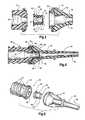
- FIG. 6is a fragmentary exploded perspective of a split valve assembly similar to FIG. 5 but including a different slit valve component;
- FIG. 7is an enlarged perspective of the nipple-shaped slit valve component shown in FIG. 6 ;
- FIG. 8is a perspective with parts shown in cross-section taken along lines 8 - 8 of FIG. 7 ;
- FIG. 9is a perspective of the slit valve component of FIG. 7 , shown flexed so as to accommodate a greater infusion flow;
- FIG. 10is a perspective of the slit valve component of FIG. 7 , shown flexed so as to accommodate a lesser aspiration flow;
- FIG. 11is perspective of another nipple-shaped slit valve embodiment
- FIG. 12is a perspective with parts shown in cross-section taken along lines 12 - 12 of FIG. 11 ;
- FIG. 13is a perspective of the nipple-shaped valve component of FIGS. 3 and 4 ;
- FIG. 14is a perspective with parts shown in cross-section taken along lines 14 - 14 of FIG. 13 ;
- FIG. 15is a perspective of the bulbous slit valve of FIG. 13 , shown flexed so as to accommodate a lesser aspiration flow;
- FIG. 16is a perspective with parts shown in cross-section taken along lines 16 - 16 of FIG. 15 ;
- FIG. 17is a perspective of the cup-shaped outdwelling slit valve of FIG. 13 , shown flexed so as to accommodate a greater infusion flow;
- FIG. 18is a perspective with parts shown in cross-section taken along lines 18 - 18 of FIG. 17 ;
- FIG. 19is an enlarged perspective of a further outdwelling cup-shaped medical slit valve of the present invention.
- FIG. 20is a perspective with parts shown in cross-section taken along lines 20 - 20 of FIG. 19 ;
- FIG. 21is an enlarged cross section of a slit having a tapered end edge
- FIG. 22is an enlarged cross section of a slit located in a flat having a greater surface area on one side than the other.
- the present inventionsolves or reduces past problems primarily in the catheter-related cardiovascular slit valve field, but also applicable to the human respiratory system and other body cavities.
- One or more normally closed cup-shaped slit valveswhich may be in a variety of forms, are outdwelling, being disposed remote from the distal end of each catheter tube of a medical patient whereby problems of the past are greatly reduced, if not eliminated.
- the term outdwellingis used to mean placement of the slit valve at the proximal end of a cannula, the distal end of which is disposed within a body cavity for fluid flow purposes.
- outdwellingembraces both placement of the slit valve outside the body of a patient or placed subcutaneously at a non-cavity site for safety purposes only, such as in conjunction with an implanted port to control, at the proximal end of a cannula, the flow of liquid from the port to a body discharge site remote from the port and the slit valve.
- the slit valvesin proximal regions of catheter tubes, comprise one or more normally closed slit valves disposed in a two-part housing.
- the slit valvesaccommodate bidirectional flow.
- two-wayit is meant that a given proximal outdwelling slit-valve both aspirates and infuses fluid, respectively, at different points in time from and into the associated catheter tube or cannula.
- an outdwelling cup-shaped slit valvemay comprise from one normally closed slit up to several normally closed slits, located on planar distal flats. It is not necessary that all slits have the same length or thickness, but the slit sites are centrally thinner than other parts of the slit valve. Some may extend into or across the apex or tip of the nipple-shaped slit valve. The slits may also extend into the wall of the central portion of the slit valve to assist in providing greater infusion flow compared to aspiration flow.
- the preferred materials for forming the slit component of the slit valvecomprise medical grade silicone rubber, polyurethane and other suitable natural and synthetic elastomeric materials.
- the other components of the slit valvemay comprise medical grade synthetic resinous or elastomeric materials.
- the material comprising each slit componentmust have sufficient flexibility for the slit lips forming the normally closed slit to flex inwardly and outwardly, respectively, when predetermined pressure differentials are imposed on the slit diaphragm, in order to accommodate fluid flow in the direction desired. Treating the slit lips with a softening composition is known in the art and may take place to provide the desired flexibility.
- the slit in the cup-shaped slit valvemay be disposed transversely or radially or diagonally or otherwise, as deemed most appropriate by those having skill in the art. Opposing slit valves located on different sides of the distal end of a slit valve may be used.
- This inventioncomprises a slit valve located in a cup-shaped hub attached at the proximal end of a catheter, the distal end of which is indwelling.
- the cathetermay be used to control fluid flow in and out of the body.
- Infusaidssuch as saline, blood, hyper alimentation, or any medication prescribed for a patient, may be administered intravenously through the catheter.
- a paramount purpose of slit valves according to the present inventionis to provide safety to the patient while the catheter is in use. Pressures inside and outside of the body have been known to cause blood to enter the catheter, which may clot or allow air in an open system to enter the body.
- Slit valves of the present inventionhave more flexibility to withstand pressures and allow greater controllability of the opening and closing of the slit valves during times of use and non-use when protection is needed.
- each slitlocated in a flat of an outdwelling cup-shaped slit valve.
- the location, length of each slit and wall thicknessallow for variation in valve functions. For instance, the varying of the slit wall thickness and or slit length has an effect, to some extent, on the pressure differential required to open the valve.
- the use of more than one slit in planar flat locationswill affect flow, but not necessarily opening or closing pressures.
- one slit, which transverses two or more valve flatscan impact opening pressures in one direction and not the other.
- Material propertiesalso have an effect on the opening and closing of valves, i.e., if the material is soft, the valves will act different than if the material is of higher durometer. This creates the ability to adjust the configuration of the slit valve or valves and select a material to produce an effective valve for the purpose intended.
- the present inventionaccommodates the following:
- any normally closed cup-shaped outdwelling slit valve of this inventionmay be used for infusing and aspirating and may be any of several configurations.
- Each of the cup-shaped slit valves shown in the Figurescomprises one-piece construction, with each slit valve typically placed within an outdwelling housing positioned external of a medical patient in a proximal relation to a hollow cannula, which selectively accommodates fluid flow to and from a medical patient.
- FIG. 1is intended to be representative of placement of outdwelling slit valves in accordance with the present invention external, i.e. outdwelling of the medical patient where a hollow cannula 30 comprising an open end 32 is disposed within a body cavity 34 of a medical patient 36 .
- the slit valve of FIG. 1is concealed within a housing, generally designated 38 , comprising interconnected distal and proximal housing parts 40 and 42 .
- the slit valve within the housing 38accommodates selective fluid flow into and from the patient 36 , based upon the slit valve being subjected to a predetermined pressure differential, i.e., the difference between the pressure on the distal side in tube 30 and the pressure on the proximal side in tube 44 .
- the body cavity 34is a cardiovascular vein, where the fluid flow comprises liquid displacement, liquid displacement in other body cavities is contemplated, as is gaseous flow from and to other body cavities.
- FIGS. 2-5illustrate additional views of the two-part housing 38 of FIG. 1 and a cup-shaped slit valve 60 within the housing 38 .
- the exterior of the proximal housing part 42comprises an exposed luer lock thread 46 and a hollow interior 48 to accommodate selective fluid flow.
- Thread 46accommodates luer lock threaded connection with a luer lock fitting at the distal end of hollow proximal tube 44 ( FIG. 1 ) in a conventional manner.
- Distal housing part 40comprises a tapered elongated tip 50 sized to accommodate a press-fit overlapping connected relationship with the proximal end of the cannula 30 , the cannula 30 being illustrated as a hollow catheter tube of synthetic resinous material of medical grade having a distal opening 32 (FIG. 1 ).
- the interior of the distal housing part 40comprises the hollow passageway 52 accommodating selective fluid flow and an enlarged slit valve receiving compartment 54 .
- proximal and distal housing parts 42 and 40are connected at interface 56 in an interlocking male-female relationship, with or without a bonding agent, as determined by those skilled in the art.
- the housing parts 40 and 42may be either separable or inseparable.
- a one-piece normally closed cup-shaped blunt end slit valveContained in compartment 54 , as shown in FIG. 3 , is a one-piece normally closed cup-shaped blunt end slit valve, generally designated 60 .
- the slit valve 60comprises a proximal flange 62 , which, when assembled, is compressively trapped between and compressively secured between the two housing parts 40 and 42 , as best shown in FIG. 3 .
- FIG. 3illustrates flange 62 is firmly retained between a distal shoulder 64 of housing part 40 and proximal shoulder 66 of housing part 42 .
- the central portion 68 of the slit valve 60is annular at the outside and the inside at hollow 48 .
- the blunt end-cup-shaped slit valve 60comprises annular hollow central portion 68 of essentially uniform inside and outside diameter ending in a blunt thin wall tip 76 .
- the distal end at tip 76is equipped with at least one normally closed radially directed slit 78 comprised of opposed flexible normally contiguous lips 80 ( FIGS. 15-18 ).
- the slit 78is placed in a flat region (a flat) of the slit valve. Where only one slit is used in the slit valve, that slit may wrap around annular corner 79 and extend into the annular wall 68 as shown in FIGS. 3-5 and thus accommodate greater infusion than aspiration fluid flow, as shown in FIGS. 5-18 , when predetermined pressure differentials are reached.
- the slit valve 84 of FIG. 6is comprised of the previously-described proximal flange 63 , a shorter central annular portion 68 and a tapered distal portion 74 , but comprised of four flats 82 , each flat being equipped with a diagonally disposed slit 78 .
- Each slitextends from the distal tip 77 proximally and diagonally a short distance into the annular central portion 68 .
- Any of the four slits 78 of cup-shaped slit valve 84is sized, shaped and formulated to accommodate influent infusion and effluent aspiration when, in each case, a threshold pressure differential is reached to accommodate fluid flow.
- the threshold pressure differential necessary to operate each slit valve of FIG. 6may be the same or different, as determined those of skill in the art, taking into account the intended function of each slit valve.
- the slit valve 84is shown in its normally closed configuration in FIG. 7-8 and flexed by pressure differential into an open effluent flow configuration in FIG. 9 and an open influent flow configuration in FIG. 10 .
- cup-shaped outdwelling slit valvegenerally designated 86 , which comprises the previously mentioned flange 62 and central portion 68 , as well as a distally extending convergingly-shaped tapered distal portion 79 and a distal tip 81 .
- the cup-shaped slit valve 86comprises a single two-way slit 83 , which continuously traverses through the two oppositely sloped converging flats 82 , across tip 81 , and proximally beyond both flats 82 at two locations into the wall of the central portion 68 .
- Slit 83accommodates both infusion and aspiration at different rates.
- FIGS. 9 , 10 and 15 - 17illustrate the manner in which each normally closed slit is flexed at respective pressure differential thresholds to accommodate infusion and aspiration, respectively.
- infusion fluidreaches a proximal pressure within the interior of the cup-shaped slit valve which, compared to the distal pressure on the slit valve, creates the necessary pressure differential threshold to accommodate opening of the slit by flexing the lips 80 away from their normally closed contiguous relation to the open condition illustrated in FIGS. 9 , 17 and 18 , accommodating infusion flow at a selected rate.
- the ratemay be controlled to less than a maximum by spacing the slit 78 in question in close proximity to the adjacent housing surface.
- FIGS. 19 and 20illustrate a further cup-shaped outdwelling slit valve, generally designated 120 , in accordance with principles of the present invention.
- Slit valve 120comprises the previously described proximal flange 62 and hollow intermediate central cylindrical section 68 , though somewhat truncated.
- the distal end of the slit valve 120comprises a flat or planar diagonally-directed or beveled thin end wall 122 integrally joined at corner 124 to the cylindrical central section 68 .
- End wall 122comprises a normally closed slit 125 , which extends centrally across the entire end wall 122 and also a short distance proximally, top and bottom, into the cylindrical wall 68 .
- the end-to-end length of the slit 78 of FIGS. 19 and 20exceeds the diameter of the cylindrical wall 68 , thereby accommodating a large opening and a higher fluid flow rate when a pressure differential in either direction of a specific threshold causes the normally contiguous lips 127 of the slit 125 to flex away from each other and the normally closed slit 125 to open. A lesser aspirating rate or a greater infusion rate is then accommodated.
- the influent verses effluent rate differentialcan be set at least in part by causing the slit to comprise angular end edges 129 as shown in FIG. 21 . Also, the structure defining the end edges 131 of the slit as shown in FIG. 22 typically causes the slit ends to constrict during aspiration and to separate during infusion 131 so the flow path is large for infusion than aspiration.
- the distal section of the disclosed slit valvescomprising at least one planar flat against which an influent-directed and effluent-directed pressure differential is imposed on interior and exterior parallel surfaces of each planar flat having a uniform thickness substantially less than the thickness of the central portion.
- at least one normally closed slitis disposed in each planar flat extending between the exterior and interior surface thereof which slit comprises yieldable lips which selectively open to accommodate fluid flow through the slit in either of two directions, responsive to predetermined pressure differentials, in greater amounts when flow is in a distal direction than in a proximal direction.
- each planar flathas a normally closed slit disposed therein.
- Each planar flatmay be located in the slit valve so as to be transversely disposed, or diagonally disposed or both transversely and diagonally disposed. It has been found that the superior results are gained when the normally closed slit extends beyond its planar flat into the central portion at one or both ends and where the thickness of the normally closed slit is less in the planar flat than in the central portion of the slit valve.
- the slitmay bridge between two spaced flats across the distal tip of the slit valve.
Landscapes
- Health & Medical Sciences (AREA)
- Engineering & Computer Science (AREA)
- Heart & Thoracic Surgery (AREA)
- General Engineering & Computer Science (AREA)
- Hematology (AREA)
- Biomedical Technology (AREA)
- Anesthesiology (AREA)
- Life Sciences & Earth Sciences (AREA)
- Animal Behavior & Ethology (AREA)
- General Health & Medical Sciences (AREA)
- Public Health (AREA)
- Veterinary Medicine (AREA)
- Pulmonology (AREA)
- Mechanical Engineering (AREA)
- Infusion, Injection, And Reservoir Apparatuses (AREA)
Abstract
Description
- 1. Use of one or more slits, each slit extended through an outside flat surface to opposite inner flat surface. Each slit is essentially at least as long as the outer planar flat surface in which the slit is located. The slit may however extend beyond the flat surface across the adjoining apex or tip and/or into the wall of the central portion of the slit valve.
- 2. Each valve accommodates bi-directional flow under certain conditions. In other words, fluid can flow in either of two directions through the slit. At any point in time when at rest, the slit valve remains normally closed, as is true when pressures are under the pressure differential needed to open the valve in one direction or the other.
- 3. The slits of the present slit valves flex or yawn into oppositely open positions so as to provide a greater influent (infusion) flow than an effluent (aspiration) flow.
- 4. The difference in valve opening pressures on each side of the valve allows the valve, when closed, to hold back both positive and negative cardiovascular pressures. The vascular system creates higher positive pressures than negative pressures so the valve accommodates this difference to open effectively in both directions when the predetermined differential pressures are respectively reached.
- 5. Where more than one slit in a given valve is used, the slits may work simultaneously or separately one from the other, but each operates on its own responsive to the desired pressure differential. The benefit is more total slit length accommodating more flow in either direction, without compromising performance.
- 6. The end portion of various slit components (diaphragms) of the slit valves may be shaped differently to create the longer slits, which may increase flow rates, but also allow the slit tips to be flexed in such a way as to provide different distal and proximal flow rates through the same slit.
- 7. In all of the slit components, the slit thickness extends between two flat parallel surfaces comprising a thin planar flat. The inner flat surface may be smaller than the outer flat surface so the flex is greater in the distal direction than the proximal direction. A slit extending the length of the outer flat surface (or beyond) will, therefore, open to a larger extent than when opened inwardly. This allows the opening pressure to be lower when flexed in the outward direction than when opened in the inward direction.
Claims (8)
Priority Applications (1)
| Application Number | Priority Date | Filing Date | Title |
|---|---|---|---|
| US12/455,244US8092432B2 (en) | 2005-05-03 | 2009-05-29 | Outdwelling slit valves and assemblies for medical liquid flow through a cannula and related methods |
Applications Claiming Priority (2)
| Application Number | Priority Date | Filing Date | Title |
|---|---|---|---|
| US11/121,342US20060253084A1 (en) | 2005-05-03 | 2005-05-03 | Outdwelling slit valves and assemblies for medical liquid flow through a cannula and related methods |
| US12/455,244US8092432B2 (en) | 2005-05-03 | 2009-05-29 | Outdwelling slit valves and assemblies for medical liquid flow through a cannula and related methods |
Related Parent Applications (1)
| Application Number | Title | Priority Date | Filing Date |
|---|---|---|---|
| US11/121,342Continuation-In-PartUS20060253084A1 (en) | 2005-05-03 | 2005-05-03 | Outdwelling slit valves and assemblies for medical liquid flow through a cannula and related methods |
Publications (2)
| Publication Number | Publication Date |
|---|---|
| US20090259175A1 US20090259175A1 (en) | 2009-10-15 |
| US8092432B2true US8092432B2 (en) | 2012-01-10 |
Family
ID=41164579
Family Applications (1)
| Application Number | Title | Priority Date | Filing Date |
|---|---|---|---|
| US12/455,244Expired - Fee RelatedUS8092432B2 (en) | 2005-05-03 | 2009-05-29 | Outdwelling slit valves and assemblies for medical liquid flow through a cannula and related methods |
Country Status (1)
| Country | Link |
|---|---|
| US (1) | US8092432B2 (en) |
Cited By (19)
| Publication number | Priority date | Publication date | Assignee | Title |
|---|---|---|---|---|
| US20100298774A1 (en)* | 2009-05-19 | 2010-11-25 | Igov Igor | Methods and devices for laparoscopic surgery |
| US20110208007A1 (en)* | 2010-01-20 | 2011-08-25 | EON Surgical Ltd. | Rapid Laparoscopy Exchange System And Method Of Use Thereof |
| US20130014836A1 (en)* | 2011-07-14 | 2013-01-17 | John Cain | Pump adaptor |
| CN104487379A (en)* | 2012-05-21 | 2015-04-01 | 可口可乐公司 | Bag-in-box connector system |
| US9238129B2 (en) | 2000-07-11 | 2016-01-19 | Icu Medical, Inc. | Medical connector |
| US9278206B2 (en) | 2009-03-25 | 2016-03-08 | Icu Medical, Inc. | Medical connectors and methods of use |
| US9750926B2 (en) | 2010-05-17 | 2017-09-05 | Icu Medical, Inc. | Medical connectors and methods of use |
| US9884176B2 (en) | 2004-11-05 | 2018-02-06 | Icu Medical, Inc. | Medical connector |
| US10052088B2 (en) | 2010-01-20 | 2018-08-21 | EON Surgical Ltd. | System and method of deploying an elongate unit in a body cavity |
| US10143989B2 (en) | 2013-05-07 | 2018-12-04 | Gencell Biosystems Ltd. | Stabilisation features |
| WO2019046456A1 (en) | 2017-08-31 | 2019-03-07 | I-V Access Technology, Inc. | Methods and devices for vascular access |
| US20200179646A1 (en)* | 2017-09-29 | 2020-06-11 | Terumo Kabushiki Kaisha | Catheter assembly and medical valve |
| US11318286B2 (en) | 2020-03-23 | 2022-05-03 | I-V Access Technology, Inc. | Catheter needle assembly with enclosable needle |
| US11324939B2 (en)* | 2017-08-31 | 2022-05-10 | I-V Access Technology, Inc. | Methods and devices for vascular access |
| US11364372B2 (en) | 2013-12-11 | 2022-06-21 | Icu Medical, Inc. | Check valve |
| WO2022178506A1 (en)* | 2021-02-19 | 2022-08-25 | I-V Access Technology, Inc. | Methods and devices for vascular access |
| US11607525B1 (en) | 2022-06-30 | 2023-03-21 | I-V Access Technology, Inc. | Methods and devices for vascular access |
| USD1003434S1 (en) | 2010-03-23 | 2023-10-31 | Icu Medical, Inc. | Medical connector seal |
| US12440661B2 (en) | 2022-05-18 | 2025-10-14 | Icu Medical, Inc. | Medical fluid transfer device |
Families Citing this family (14)
| Publication number | Priority date | Publication date | Assignee | Title |
|---|---|---|---|---|
| US8603029B2 (en) | 2007-10-10 | 2013-12-10 | Hospi Corporation | Apparatuses and methods for medication administration |
| US9775980B2 (en)* | 2008-09-23 | 2017-10-03 | Hospi Corporation | Valved enteral administration assembly |
| DE102010012018A1 (en)* | 2010-03-12 | 2011-09-15 | Kaco Gmbh + Co. Kg | vent valve |
| EP2615980B1 (en)* | 2010-09-19 | 2017-08-16 | EON Surgical Ltd. | Micro laparoscopy devices and deployments thereof |
| WO2012118852A2 (en)* | 2011-02-28 | 2012-09-07 | Normedix Llc | Hemostasis sealing device |
| US9155864B2 (en)* | 2011-10-06 | 2015-10-13 | Becton, Dickinson And Company | Multiple use blood control valve with center and circumferential slits |
| US9162806B2 (en)* | 2012-05-21 | 2015-10-20 | The Coca-Cola Company | Bag in box cleanable connector system having conical plunger |
| US9327095B2 (en)* | 2013-03-11 | 2016-05-03 | Becton, Dickinson And Company | Blood control catheter with antimicrobial needle lube |
| US9592367B2 (en) | 2013-07-30 | 2017-03-14 | Becton, Dickinson And Company | Blood control catheter valve employing actuator with flexible retention arms |
| WO2016007650A1 (en)* | 2014-07-08 | 2016-01-14 | Applied Medical Resources Corporation | Highly responsive instrument seal |
| DE102014213947A1 (en)* | 2014-07-17 | 2016-01-21 | B. Braun Melsungen Ag | Closure device for a fluid system for medical purposes |
| US10391292B2 (en) | 2016-06-15 | 2019-08-27 | Surmodics, Inc. | Hemostasis sealing device with constriction ring |
| US10758719B2 (en) | 2016-12-15 | 2020-09-01 | Surmodics, Inc. | Low-friction sealing devices |
| DE102020209931A1 (en)* | 2020-08-06 | 2022-02-10 | B. Braun Melsungen Aktiengesellschaft | catheter assembly |
Citations (23)
| Publication number | Priority date | Publication date | Assignee | Title |
|---|---|---|---|---|
| US703101A (en) | 1901-06-08 | 1902-06-24 | Walter F Ware | Medicine-dropper. |
| US2069105A (en) | 1932-03-14 | 1937-01-26 | John F Engle | Air valve |
| US2629393A (en) | 1949-05-05 | 1953-02-24 | Jesse D Langdon | Combined check valve and vent valve |
| US3525357A (en) | 1968-11-18 | 1970-08-25 | Waters Co The | Pump valve apparatus |
| US3620500A (en) | 1970-02-04 | 1971-11-16 | Deseret Pharma | Variable aperture fluid flow control apparatus |
| US3941149A (en) | 1974-11-11 | 1976-03-02 | Baxter Laboratories, Inc. | Valve |
| US4084606A (en) | 1974-04-23 | 1978-04-18 | Baxter Travenol Laboratories, Inc. | Fluid transfer device |
| US4143853A (en) | 1977-07-14 | 1979-03-13 | Metatech Corporation | Valve for use with a catheter or the like |
| US4341239A (en) | 1980-07-14 | 1982-07-27 | Vernay Laboratories, Inc. | Combination check-overpressure relief valve |
| US4434810A (en) | 1980-07-14 | 1984-03-06 | Vernay Laboratories, Inc. | Bi-directional pressure relief valve |
| US4535818A (en) | 1983-09-26 | 1985-08-20 | Vernay Laboratories, Inc. | Valve assembly |
| US4535819A (en) | 1984-06-04 | 1985-08-20 | Vernay Laboratories, Inc. | Valve assembly |
| US4566493A (en) | 1985-02-21 | 1986-01-28 | Vernay Laboratories, Inc. | Valve assembly |
| US4671796A (en) | 1983-05-03 | 1987-06-09 | Catheter Technology Corp. | Valved two-way catheter |
| US4883456A (en) | 1988-02-22 | 1989-11-28 | Holter John W | Attitude and pressure responsive valve |
| US4968294A (en) | 1989-02-09 | 1990-11-06 | Salama Fouad A | Urinary control valve and method of using same |
| US4995863A (en) | 1986-10-06 | 1991-02-26 | Catheter Technology Corporation | Catheter with slit valve |
| US5033504A (en) | 1989-01-25 | 1991-07-23 | Bph Patent Holding Ag | Automatic relief valve |
| US5112301A (en) | 1991-06-19 | 1992-05-12 | Strato Medical Corporation | Bidirectional check valve catheter |
| US5169393A (en) | 1990-09-04 | 1992-12-08 | Robert Moorehead | Two-way outdwelling slit valving of medical liquid flow through a cannula and methods |
| US5984903A (en) | 1995-12-21 | 1999-11-16 | B. Braun Celsa | Catheter having a valve with a bi-directional axial slits |
| US20020121530A1 (en) | 2001-03-02 | 2002-09-05 | Socier Timothy R. | Multiple orifice valve |
| US20040102738A1 (en) | 2002-11-26 | 2004-05-27 | Medical Ventures, L.L.C. | Pressure actuated flow control valve |
- 2009
- 2009-05-29USUS12/455,244patent/US8092432B2/ennot_activeExpired - Fee Related
Patent Citations (23)
| Publication number | Priority date | Publication date | Assignee | Title |
|---|---|---|---|---|
| US703101A (en) | 1901-06-08 | 1902-06-24 | Walter F Ware | Medicine-dropper. |
| US2069105A (en) | 1932-03-14 | 1937-01-26 | John F Engle | Air valve |
| US2629393A (en) | 1949-05-05 | 1953-02-24 | Jesse D Langdon | Combined check valve and vent valve |
| US3525357A (en) | 1968-11-18 | 1970-08-25 | Waters Co The | Pump valve apparatus |
| US3620500A (en) | 1970-02-04 | 1971-11-16 | Deseret Pharma | Variable aperture fluid flow control apparatus |
| US4084606A (en) | 1974-04-23 | 1978-04-18 | Baxter Travenol Laboratories, Inc. | Fluid transfer device |
| US3941149A (en) | 1974-11-11 | 1976-03-02 | Baxter Laboratories, Inc. | Valve |
| US4143853A (en) | 1977-07-14 | 1979-03-13 | Metatech Corporation | Valve for use with a catheter or the like |
| US4341239A (en) | 1980-07-14 | 1982-07-27 | Vernay Laboratories, Inc. | Combination check-overpressure relief valve |
| US4434810A (en) | 1980-07-14 | 1984-03-06 | Vernay Laboratories, Inc. | Bi-directional pressure relief valve |
| US4671796A (en) | 1983-05-03 | 1987-06-09 | Catheter Technology Corp. | Valved two-way catheter |
| US4535818A (en) | 1983-09-26 | 1985-08-20 | Vernay Laboratories, Inc. | Valve assembly |
| US4535819A (en) | 1984-06-04 | 1985-08-20 | Vernay Laboratories, Inc. | Valve assembly |
| US4566493A (en) | 1985-02-21 | 1986-01-28 | Vernay Laboratories, Inc. | Valve assembly |
| US4995863A (en) | 1986-10-06 | 1991-02-26 | Catheter Technology Corporation | Catheter with slit valve |
| US4883456A (en) | 1988-02-22 | 1989-11-28 | Holter John W | Attitude and pressure responsive valve |
| US5033504A (en) | 1989-01-25 | 1991-07-23 | Bph Patent Holding Ag | Automatic relief valve |
| US4968294A (en) | 1989-02-09 | 1990-11-06 | Salama Fouad A | Urinary control valve and method of using same |
| US5169393A (en) | 1990-09-04 | 1992-12-08 | Robert Moorehead | Two-way outdwelling slit valving of medical liquid flow through a cannula and methods |
| US5112301A (en) | 1991-06-19 | 1992-05-12 | Strato Medical Corporation | Bidirectional check valve catheter |
| US5984903A (en) | 1995-12-21 | 1999-11-16 | B. Braun Celsa | Catheter having a valve with a bi-directional axial slits |
| US20020121530A1 (en) | 2001-03-02 | 2002-09-05 | Socier Timothy R. | Multiple orifice valve |
| US20040102738A1 (en) | 2002-11-26 | 2004-05-27 | Medical Ventures, L.L.C. | Pressure actuated flow control valve |
Cited By (49)
| Publication number | Priority date | Publication date | Assignee | Title |
|---|---|---|---|---|
| US9238129B2 (en) | 2000-07-11 | 2016-01-19 | Icu Medical, Inc. | Medical connector |
| US10722698B2 (en) | 2004-11-05 | 2020-07-28 | Icu Medical, Inc. | Medical connector |
| US11883623B2 (en) | 2004-11-05 | 2024-01-30 | Icu Medical, Inc. | Medical connector |
| US9884176B2 (en) | 2004-11-05 | 2018-02-06 | Icu Medical, Inc. | Medical connector |
| US10391293B2 (en) | 2009-03-25 | 2019-08-27 | Icu Medical, Inc. | Medical connectors and methods of use |
| US11931539B2 (en) | 2009-03-25 | 2024-03-19 | Icu Medical, Inc. | Medical connectors and methods of use |
| US12102786B2 (en) | 2009-03-25 | 2024-10-01 | Icu Medical, Inc. | Medical connector with elongated portion within seal collar |
| US9278206B2 (en) | 2009-03-25 | 2016-03-08 | Icu Medical, Inc. | Medical connectors and methods of use |
| US9440060B2 (en) | 2009-03-25 | 2016-09-13 | Icu Medical, Inc. | Medical connectors and methods of use |
| US10799692B2 (en) | 2009-03-25 | 2020-10-13 | Icu Medical, Inc. | Medical connectors and methods of use |
| US12059545B2 (en) | 2009-03-25 | 2024-08-13 | Icu Medical, Inc. | Medical connector with elongated portion within seal collar |
| US12285584B2 (en) | 2009-03-25 | 2025-04-29 | Icu Medical, Inc. | Medical connector with elongated portion within seal collar |
| US11376411B2 (en) | 2009-03-25 | 2022-07-05 | Icu Medical, Inc. | Medical connectors and methods of use |
| US11896795B2 (en) | 2009-03-25 | 2024-02-13 | Icu Medical, Inc | Medical connector having elongated portion within closely conforming seal collar |
| US10086188B2 (en) | 2009-03-25 | 2018-10-02 | Icu Medical, Inc. | Medical connectors and methods of use |
| US11986618B1 (en) | 2009-03-25 | 2024-05-21 | Icu Medical, Inc. | Medical connector having elongated portion within seal collar |
| US9737332B2 (en) | 2009-05-19 | 2017-08-22 | Teleflex Medical Incorporated | Methods and devices for laparoscopic surgery |
| US10499948B2 (en) | 2009-05-19 | 2019-12-10 | Teleflex Medical Incorporated | Methods and devices for laparoscopic surgery |
| US20100298774A1 (en)* | 2009-05-19 | 2010-11-25 | Igov Igor | Methods and devices for laparoscopic surgery |
| US9138207B2 (en) | 2009-05-19 | 2015-09-22 | Teleflex Medical Incorporated | Methods and devices for laparoscopic surgery |
| US10052088B2 (en) | 2010-01-20 | 2018-08-21 | EON Surgical Ltd. | System and method of deploying an elongate unit in a body cavity |
| US10028652B2 (en) | 2010-01-20 | 2018-07-24 | EON Surgical Ltd. | Rapid laparoscopy exchange system and method of use thereof |
| US8721539B2 (en) | 2010-01-20 | 2014-05-13 | EON Surgical Ltd. | Rapid laparoscopy exchange system and method of use thereof |
| US20110208007A1 (en)* | 2010-01-20 | 2011-08-25 | EON Surgical Ltd. | Rapid Laparoscopy Exchange System And Method Of Use Thereof |
| USD1003434S1 (en) | 2010-03-23 | 2023-10-31 | Icu Medical, Inc. | Medical connector seal |
| USD1029246S1 (en) | 2010-03-23 | 2024-05-28 | Icu Medical, Inc. | Medical connector seal |
| US10195413B2 (en) | 2010-05-17 | 2019-02-05 | Icu Medical, Inc. | Medical connectors and methods of use |
| US11071852B2 (en) | 2010-05-17 | 2021-07-27 | Icu Medical, Inc. | Medical connectors and methods of use |
| US9750926B2 (en) | 2010-05-17 | 2017-09-05 | Icu Medical, Inc. | Medical connectors and methods of use |
| US20130014836A1 (en)* | 2011-07-14 | 2013-01-17 | John Cain | Pump adaptor |
| CN104487379A (en)* | 2012-05-21 | 2015-04-01 | 可口可乐公司 | Bag-in-box connector system |
| US10143989B2 (en) | 2013-05-07 | 2018-12-04 | Gencell Biosystems Ltd. | Stabilisation features |
| US11364372B2 (en) | 2013-12-11 | 2022-06-21 | Icu Medical, Inc. | Check valve |
| US10850069B2 (en)* | 2017-08-31 | 2020-12-01 | I-V Access Technology, Inc. | Methods and devices for vascular access |
| US11324939B2 (en)* | 2017-08-31 | 2022-05-10 | I-V Access Technology, Inc. | Methods and devices for vascular access |
| US11701495B2 (en)* | 2017-08-31 | 2023-07-18 | I-V Access Technology, Inc. | Methods and devices for vascular access |
| US20210031009A1 (en)* | 2017-08-31 | 2021-02-04 | I-V Access Technology, Inc. | Methods and devices for vascular access |
| US20200061346A1 (en)* | 2017-08-31 | 2020-02-27 | I-V Access Technology, Inc. | Methods and devices for vascular access |
| US11890447B2 (en) | 2017-08-31 | 2024-02-06 | I-V Access Technology, Inc. | Methods and devices for vascular access |
| US12239814B2 (en) | 2017-08-31 | 2025-03-04 | I-V Access Technology, Inc. | Methods and devices for vascular access |
| WO2019046456A1 (en) | 2017-08-31 | 2019-03-07 | I-V Access Technology, Inc. | Methods and devices for vascular access |
| EP3651845A4 (en)* | 2017-08-31 | 2021-07-21 | I-V Access Technology, Inc. | METHODS AND DEVICES FOR VASCULAR ACCESS |
| JP2020532366A (en)* | 2017-08-31 | 2020-11-12 | アイ−ブイ アクセス テクノロジー,インコーポレイティド | Methods and devices for vascular access |
| US20200179646A1 (en)* | 2017-09-29 | 2020-06-11 | Terumo Kabushiki Kaisha | Catheter assembly and medical valve |
| US12415055B2 (en)* | 2017-09-29 | 2025-09-16 | Terumo Kabushiki Kaisha | Catheter assembly and medical valve |
| US11318286B2 (en) | 2020-03-23 | 2022-05-03 | I-V Access Technology, Inc. | Catheter needle assembly with enclosable needle |
| WO2022178506A1 (en)* | 2021-02-19 | 2022-08-25 | I-V Access Technology, Inc. | Methods and devices for vascular access |
| US12440661B2 (en) | 2022-05-18 | 2025-10-14 | Icu Medical, Inc. | Medical fluid transfer device |
| US11607525B1 (en) | 2022-06-30 | 2023-03-21 | I-V Access Technology, Inc. | Methods and devices for vascular access |
Also Published As
| Publication number | Publication date |
|---|---|
| US20090259175A1 (en) | 2009-10-15 |
Similar Documents
| Publication | Publication Date | Title |
|---|---|---|
| US8092432B2 (en) | Outdwelling slit valves and assemblies for medical liquid flow through a cannula and related methods | |
| US20060253084A1 (en) | Outdwelling slit valves and assemblies for medical liquid flow through a cannula and related methods | |
| US5554136A (en) | Dual lumen infusion/aspiration catheter | |
| EP0328332B2 (en) | Catheter valve assembly | |
| US5807349A (en) | Catheter having valve mechanism | |
| JP2584588B2 (en) | Bi-directional valve catheter | |
| US7413564B2 (en) | Slit valve catheters | |
| US20050043703A1 (en) | Slit valves for catheter tips and methods | |
| US5147332A (en) | Multi-valve catheter for improved reliability | |
| US20050283122A1 (en) | Slit valves bridging between the tip and distal side wall of catheter tubes and methods | |
| EP1019131B1 (en) | Medical fluid infusion and aspiration | |
| CN203208510U (en) | Catheter component | |
| US5176652A (en) | Hemostasis valve | |
| US5224938A (en) | Valved catheter | |
| US5522807A (en) | Dual lumen infusion/aspiration catheter | |
| US8034035B2 (en) | Pressure activated safety valve with high flow slit | |
| US10130750B2 (en) | Pressure activated valve with high flow slit | |
| JPH0898891A (en) | Catheter tube | |
| JPH04246370A (en) | Cardiovascular assembly | |
| JP4480919B2 (en) | Abdominal-venous shunt catheter | |
| KR20220134334A (en) | foley catheter |
Legal Events
| Date | Code | Title | Description |
|---|---|---|---|
| AS | Assignment | Owner name:NORDGREN CORPORATION, IOWA Free format text:ASSIGNMENT OF ASSIGNORS INTEREST;ASSIGNOR:NORDGREN, GREG;REEL/FRAME:022896/0073 Effective date:20090526 | |
| ZAAA | Notice of allowance and fees due | Free format text:ORIGINAL CODE: NOA | |
| ZAAB | Notice of allowance mailed | Free format text:ORIGINAL CODE: MN/=. | |
| STCF | Information on status: patent grant | Free format text:PATENTED CASE | |
| FEPP | Fee payment procedure | Free format text:PATENT HOLDER CLAIMS MICRO ENTITY STATUS, ENTITY STATUS SET TO MICRO (ORIGINAL EVENT CODE: STOM); ENTITY STATUS OF PATENT OWNER: SMALL ENTITY Free format text:PAT HLDR NO LONGER CLAIMS MICRO ENTITY STATE, ENTITY STATUS SET TO SMALL (ORIGINAL EVENT CODE: MTOS); ENTITY STATUS OF PATENT OWNER: SMALL ENTITY | |
| FPAY | Fee payment | Year of fee payment:4 | |
| MAFP | Maintenance fee payment | Free format text:PAYMENT OF MAINTENANCE FEE, 8TH YR, SMALL ENTITY (ORIGINAL EVENT CODE: M2552); ENTITY STATUS OF PATENT OWNER: SMALL ENTITY Year of fee payment:8 | |
| FEPP | Fee payment procedure | Free format text:MAINTENANCE FEE REMINDER MAILED (ORIGINAL EVENT CODE: REM.); ENTITY STATUS OF PATENT OWNER: SMALL ENTITY | |
| LAPS | Lapse for failure to pay maintenance fees | Free format text:PATENT EXPIRED FOR FAILURE TO PAY MAINTENANCE FEES (ORIGINAL EVENT CODE: EXP.); ENTITY STATUS OF PATENT OWNER: SMALL ENTITY | |
| STCH | Information on status: patent discontinuation | Free format text:PATENT EXPIRED DUE TO NONPAYMENT OF MAINTENANCE FEES UNDER 37 CFR 1.362 | |
| FP | Lapsed due to failure to pay maintenance fee | Effective date:20240110 |