US8091923B2 - Adaptive seat belt load limiter and method - Google Patents
Adaptive seat belt load limiter and methodDownload PDFInfo
- Publication number
- US8091923B2 US8091923B2US12/147,533US14753308AUS8091923B2US 8091923 B2US8091923 B2US 8091923B2US 14753308 AUS14753308 AUS 14753308AUS 8091923 B2US8091923 B2US 8091923B2
- Authority
- US
- United States
- Prior art keywords
- tube
- load limiter
- load
- buckle
- vehicle
- Prior art date
- Legal status (The legal status is an assumption and is not a legal conclusion. Google has not performed a legal analysis and makes no representation as to the accuracy of the status listed.)
- Active, expires
Links
Images


Classifications
- B—PERFORMING OPERATIONS; TRANSPORTING
- B60—VEHICLES IN GENERAL
- B60R—VEHICLES, VEHICLE FITTINGS, OR VEHICLE PARTS, NOT OTHERWISE PROVIDED FOR
- B60R22/00—Safety belts or body harnesses in vehicles
- B60R22/28—Safety belts or body harnesses in vehicles incorporating energy-absorbing devices
- B—PERFORMING OPERATIONS; TRANSPORTING
- B60—VEHICLES IN GENERAL
- B60R—VEHICLES, VEHICLE FITTINGS, OR VEHICLE PARTS, NOT OTHERWISE PROVIDED FOR
- B60R22/00—Safety belts or body harnesses in vehicles
- B60R22/28—Safety belts or body harnesses in vehicles incorporating energy-absorbing devices
- B60R2022/286—Safety belts or body harnesses in vehicles incorporating energy-absorbing devices using deformation of material
- B—PERFORMING OPERATIONS; TRANSPORTING
- B60—VEHICLES IN GENERAL
- B60R—VEHICLES, VEHICLE FITTINGS, OR VEHICLE PARTS, NOT OTHERWISE PROVIDED FOR
- B60R22/00—Safety belts or body harnesses in vehicles
- B60R22/28—Safety belts or body harnesses in vehicles incorporating energy-absorbing devices
- B60R2022/288—Safety belts or body harnesses in vehicles incorporating energy-absorbing devices with means to adjust or regulate the amount of energy to be absorbed
Definitions
- the present inventionrelates to a device and method for limiting the load imposed upon a seated occupant by a seat belt, and more particularly provides an energy-absorbing load limiter which is adjusted in response to sensed conditions to precisely adapt the load limitation to the needs of the occupant.
- a method and apparatus for limiting the load on a seat belt buckleincludes providing an adjustable energy absorbing device mounting the seat belt buckle on the vehicle, sensing vehicle and occupant conditions to determine the optimal adjustment of the adjustable energy absorbing device for restraint of the occupant under the sensed conditions, and adjusting the adjustable energy absorbing device in response to the sensed conditions to thereby adapt the restraint of the occupant to the sensed conditions.
- the adjustable energy absorbing deviceis an extendable strut having an end connected to the buckle and an end connected to the vehicle, the strut having metal deforming elements therein being deformed upon the load reaching a certain magnitude, and the strut having an adjusting mechanism adjusting the metal deforming elements to adjust the degree of metal deformation and thereby adjust the energy absorbing capacity of the strut.
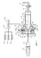
- FIG. 1is a side elevation view of the load limiting device having parts broken away and in section.
- FIG. 1Ais a view similar to FIG. 1 but showing that the adjusting mechanism has adjusted the position of the device to determine the extent of metal deformation and energy absorption by the load limiting device.
- FIG. 2is a section view taken in the direction of arrows 2 - 2 of FIG. 1 .
- FIG. 3is a section view taken in the direction of arrows 3 - 3 of FIG. 1 .
- the load limiter device generally indicated at 10is provided for mounting a seat belt buckle 28 on a vehicle generally indicated at 22 .
- the load limiter device 10includes a first tubular member 12 and a second tubular member 14 that is concentric with a central axis 16 of the first tubular member 12 and is slidable therein to form an extendible strut.
- the first tubular member 12is thus an outer tubular member and the second tubular member 14 is an inner tubular member, and these tubular members are telescopically arranged for movement therebetween.
- the first tubular member 12has a leg 20 that is attached to either the seat or a body panel of the vehicle 22 by a bolt 24 .
- the second tubular member 14has a leg 26 that is attached to the seat belt buckle 28 by a fabric strap 30 . Accordingly, when the seat belt buckle 28 is urged leftwardly by an occupant restraining force, the second tubular member 14 will travel leftwardly within the first tubular member 12 .
- a pair of plow members or shoes 36 and 38are captured between a conical ramp portion 42 of the second tubular member 14 and a conical ramp portion 44 of the first tubular member 12 so that the plow members 36 and 38 are positioned to interfere with the leftward travel of the second tubular member 14 .
- the plow members 36 and 38are shown as round balls but can be of other shapes.
- the plow members 36 and 38are held in place, and adjusted in position by an adjusting mechanism, generally indicated at 46 , as shown in the drawings.
- the adjusting mechanism 46includes an actuator plate 50 , a gear plate 52 , a pair of balls 56 and 58 , a drive gear 62 and a motor 64 .
- the adjusting mechanism 46is housed within a housing 68 provided on the first tubular member 12 .
- a bearing plate 70 of the housing 68has a journal 74 that receives a hub 76 of the gear plate 52 .
- the gear plate 52has teeth 78 that mesh with the drive gear 62 of the motor 64 .
- the balls 56 and 58are captured within tear-shaped recesses 82 and 84 of the gear plate 52 , and tear-shaped recesses 88 and 90 of the actuator plate 50 .
- the actuator plate 50has a depending leg 96 that is captured in a slot 98 of the housing 68 so that the actuator plate 50 cannot rotate.
- a control system generally indicated at 110is provided for operating the motor 64 .
- the control system 110includes a plurality of sensors 122 , 124 and 126 for sensing various conditions. These sensors can sense conditions such as vehicle speed, occupant weight, occupant position, seat position, or other operating variables. These sensors provide inputs to a controller 130 that will operate the motor 62 in response to the conditions sensed by the sensors 122 , 124 and 126 .
- the buckle 28acting through the strap 30 will urge the second tubular member 14 leftwardly as viewed in FIG. 1 .
- the restraint loadreaches a certain magnitude
- the plow shoes 36 and 38will begin to plow into the second tubular member 14 , creating grooves via the deformation of the metal of the second tubular member 14 as the second tubular member 14 travels to the left, toward the occupant. Accordingly, by virtue of the deformation of metal during the leftward travel of the second tubular member 14 , the maximum load imposed on the buckle 28 can be limited as determined by the extent of energy absorption occurring as a result of the deformation of the metal.
- the load limiter 10is an extendible strut, and the length of the strut increases as the second tubular member 14 travels to the left during the restraint of the occupant and energy is absorbed by deformation of the second of the tubular member 14 .
- the leftward travel of the inner tube 14may be limited by the provision of a stop.
- the housing 68can be engaged by the left-hand end of the inner tube 14 to stop the leftward travel.
- the right-hand end of the inner tube 14can have thickened material that withstands deformation by the plow shoes 36 and 38 to bring the inner tube to a stop.
- the load limiting device 10can be continuously or periodically adjusted by the sensors and the controller to adapt the load limiting device 10 to the restraint needs of the particular occupant under the then existing operating conditions of the vehicle.
- the load limiting deviceis replaced after the occurrence of an event that has resulted in deformation of the tubular members.
- load limiting device 10shown herein is just one example of a load limiting device for use in practicing the method of this invention.
- Another load limiting deviceis shown in my co-pending patent application, U.S. application Ser. No. 12/147,537 filed Jun. 27, 2008, now U.S. Pat. No. 7,784,831, issued Aug. 31, 2010.
- the inventionprovides a load limiting device and method by which the restraint load imposed upon a seated occupant is adapted and tailored to the particular needs of the seated occupant, depending on the operating variables, for example vehicle speed, occupant weight, etc.
- the load limiting deviceis an extendible strut that extends in length via metal deformation, and can be continuously adjusted at intervals during the driving of the vehicle, so that, upon the occurrence of an occupant restraining event, the load limiting device is ready for providing optimal restraint of the particular occupant.
Landscapes
- Engineering & Computer Science (AREA)
- Mechanical Engineering (AREA)
- Automotive Seat Belt Assembly (AREA)
Abstract
Description
Claims (10)
Priority Applications (3)
| Application Number | Priority Date | Filing Date | Title |
|---|---|---|---|
| US12/147,533US8091923B2 (en) | 2008-06-27 | 2008-06-27 | Adaptive seat belt load limiter and method |
| DE102009030511.4ADE102009030511B4 (en) | 2008-06-27 | 2009-06-25 | Load limiting device for securing a seat belt buckle |
| CN200910166933.7ACN102189975B (en) | 2008-06-27 | 2009-06-26 | Adaptive seat belt load limiter and method |
Applications Claiming Priority (1)
| Application Number | Priority Date | Filing Date | Title |
|---|---|---|---|
| US12/147,533US8091923B2 (en) | 2008-06-27 | 2008-06-27 | Adaptive seat belt load limiter and method |
Publications (2)
| Publication Number | Publication Date |
|---|---|
| US20090326765A1 US20090326765A1 (en) | 2009-12-31 |
| US8091923B2true US8091923B2 (en) | 2012-01-10 |
Family
ID=41448425
Family Applications (1)
| Application Number | Title | Priority Date | Filing Date |
|---|---|---|---|
| US12/147,533Active2030-06-03US8091923B2 (en) | 2008-06-27 | 2008-06-27 | Adaptive seat belt load limiter and method |
Country Status (3)
| Country | Link |
|---|---|
| US (1) | US8091923B2 (en) |
| CN (1) | CN102189975B (en) |
| DE (1) | DE102009030511B4 (en) |
Cited By (4)
| Publication number | Priority date | Publication date | Assignee | Title |
|---|---|---|---|---|
| US9821758B2 (en) | 2016-02-05 | 2017-11-21 | Ford Global Technologies, Llc | Pretensioning, force-limiting seat belt assembly |
| US10543807B2 (en) | 2018-01-03 | 2020-01-28 | Ford Global Technologies, Llc | Energy absorbing restraint system |
| US10821863B1 (en)* | 2019-06-24 | 2020-11-03 | Ford Global Technologies, Llc | Retention member for vehicle seating assembly |
| US11021131B2 (en) | 2017-01-23 | 2021-06-01 | Volkswagen Aktiengesellschaft | Safety belt device for a vehicle |
Families Citing this family (8)
| Publication number | Priority date | Publication date | Assignee | Title |
|---|---|---|---|---|
| US7784831B2 (en)* | 2008-06-27 | 2010-08-31 | Gm Global Technology Operations, Inc. | Seat belt load limiting device |
| FR2997352B1 (en)* | 2012-10-26 | 2016-03-25 | Dorel France Sa | CAR SEAT FOR CHILDREN WITH ACTIVE PROTECTIVE MEANS |
| EP2825422A4 (en)* | 2012-01-31 | 2016-10-19 | Rajasingham Arjuna Indraeswaran | SUPPORT FOR OCCUPANTS OF A VEHICLE |
| DE102014017788B4 (en)* | 2014-12-03 | 2020-03-26 | Trw Automotive Gmbh | Tongue |
| EP3121119B1 (en)* | 2015-07-22 | 2019-11-06 | AIRBUS HELICOPTERS DEUTSCHLAND GmbH | An energy absorbing system for absorbing energy of an object in a vehicle in a crash situation |
| DE102015010807B4 (en)* | 2015-08-21 | 2025-10-09 | Zf Automotive Germany Gmbh | Belt tensioners |
| DE102017204508A1 (en)* | 2017-03-17 | 2018-09-20 | Volkswagen Aktiengesellschaft | Seat belt device for a vehicle |
| JP2018203211A (en)* | 2017-06-09 | 2018-12-27 | 株式会社東海理化電機製作所 | Seat belt retractor |
Citations (26)
| Publication number | Priority date | Publication date | Assignee | Title |
|---|---|---|---|---|
| US3026972A (en) | 1959-04-13 | 1962-03-27 | Gen Dynamics Corp | Energy absorbing seat belt attachment |
| US3308908A (en)* | 1965-01-11 | 1967-03-14 | Lockheed Aircraft Corp | Energy absorber |
| US3680913A (en) | 1968-09-06 | 1972-08-01 | Rolf Seybold | Attachment device for a retaining belt |
| DE2301506A1 (en) | 1972-01-12 | 1973-08-02 | Nissan Motor | DEVICE FOR ABSORBING MECHANICAL ENERGY, IN PARTICULAR AS A SAFETY DEVICE |
| US3973650A (en)* | 1972-01-12 | 1976-08-10 | Nissan Motor Co., Ltd. | Mechanical energy absorbing device and safety harness using the same |
| US4258934A (en)* | 1978-05-23 | 1981-03-31 | Nippon Soken, Inc. | Seat belt tensioning device |
| US4886296A (en)* | 1987-09-25 | 1989-12-12 | Volkswagen Ag | Belt force limiting device |
| US4978139A (en)* | 1988-12-20 | 1990-12-18 | Mercedes-Benz Ag | Energy absorbing device for safety belts of motor vehicles |
| US5069482A (en) | 1989-10-09 | 1991-12-03 | Trw Repa Gmbh | Force limiter for safety belt restraining systems |
| US5431447A (en) | 1994-10-24 | 1995-07-11 | Trw Vehicle Safety Systems Inc. | Adjustable energy absorbing device for use in a vehicle seat belt restraint system |
| US5580091A (en)* | 1994-10-13 | 1996-12-03 | Takata Inc. | Energy management device for use with safety belt retractors |
| US5664807A (en) | 1995-03-29 | 1997-09-09 | Trw Occupant Restraint Systems Gmbh | Force limitation in a vehicle occupant restraining system |
| DE29820543U1 (en) | 1998-11-17 | 1999-04-29 | TRW Occupant Restraint Systems GmbH & Co. KG, 73553 Alfdorf | Fastening fitting for a belt buckle of a vehicle seat belt |
| US5971489A (en) | 1997-10-14 | 1999-10-26 | Breed Automotive Technology, Inc. | Load limiting device for a seat belt |
| US6056320A (en)* | 1998-10-23 | 2000-05-02 | Chrysler Corporation | Energy absorbing occupant restraint system |
| US6135564A (en) | 1997-10-21 | 2000-10-24 | Trw Occupant Restraint Systems Gmbh & Co. Kg | Force limiter for a vehicle occupant restraint system |
| US6199954B1 (en)* | 1998-04-03 | 2001-03-13 | Trw Occupany Restraint Systems Gmbh & Co., Kg | Belt tensioner with linear drive |
| US6299211B1 (en) | 1997-04-23 | 2001-10-09 | Trw Occupant Restraint Systems Gmbh & Co. Kg | Tensioner for a safety belt |
| US6425542B2 (en)* | 1999-12-22 | 2002-07-30 | Trw Occupant Restraint Systems Gmbh & Co. Kg | Belt retractor force limiter |
| WO2002087931A1 (en) | 2001-04-29 | 2002-11-07 | Yu, Tao | A seat belt having energy absorbing and controlling function |
| US6712394B2 (en) | 2001-02-16 | 2004-03-30 | Trw Occupant Restraint Systems Gmbh & Co. Kg | Belt tensioner |
| US7137648B2 (en) | 2003-07-14 | 2006-11-21 | Key Safety Systems, Inc. | Load limiting structure for vehicle occupant restraint system |
| DE102006034582A1 (en) | 2006-07-26 | 2008-02-14 | Trw Automotive Gmbh | Seat belt winder comprises a rotatable belt reel, a brake disk rotationally fixed to the belt reel, a brake lining, and a rotatable pressure element provided with an adjustment thread engaging in a counterthread assigned to a frame |
| US20090005935A1 (en)* | 2004-11-26 | 2009-01-01 | Anders Lenning | force limiter |
| US7784831B2 (en)* | 2008-06-27 | 2010-08-31 | Gm Global Technology Operations, Inc. | Seat belt load limiting device |
| US7997620B1 (en)* | 2010-03-10 | 2011-08-16 | GM Global Technology Operations LLC | Adaptive load-limiting seat belt buckle presenter |
- 2008
- 2008-06-27USUS12/147,533patent/US8091923B2/enactiveActive
- 2009
- 2009-06-25DEDE102009030511.4Apatent/DE102009030511B4/enactiveActive
- 2009-06-26CNCN200910166933.7Apatent/CN102189975B/enactiveActive
Patent Citations (26)
| Publication number | Priority date | Publication date | Assignee | Title |
|---|---|---|---|---|
| US3026972A (en) | 1959-04-13 | 1962-03-27 | Gen Dynamics Corp | Energy absorbing seat belt attachment |
| US3308908A (en)* | 1965-01-11 | 1967-03-14 | Lockheed Aircraft Corp | Energy absorber |
| US3680913A (en) | 1968-09-06 | 1972-08-01 | Rolf Seybold | Attachment device for a retaining belt |
| US3973650A (en)* | 1972-01-12 | 1976-08-10 | Nissan Motor Co., Ltd. | Mechanical energy absorbing device and safety harness using the same |
| DE2301506A1 (en) | 1972-01-12 | 1973-08-02 | Nissan Motor | DEVICE FOR ABSORBING MECHANICAL ENERGY, IN PARTICULAR AS A SAFETY DEVICE |
| US4258934A (en)* | 1978-05-23 | 1981-03-31 | Nippon Soken, Inc. | Seat belt tensioning device |
| US4886296A (en)* | 1987-09-25 | 1989-12-12 | Volkswagen Ag | Belt force limiting device |
| US4978139A (en)* | 1988-12-20 | 1990-12-18 | Mercedes-Benz Ag | Energy absorbing device for safety belts of motor vehicles |
| US5069482A (en) | 1989-10-09 | 1991-12-03 | Trw Repa Gmbh | Force limiter for safety belt restraining systems |
| US5580091A (en)* | 1994-10-13 | 1996-12-03 | Takata Inc. | Energy management device for use with safety belt retractors |
| US5431447A (en) | 1994-10-24 | 1995-07-11 | Trw Vehicle Safety Systems Inc. | Adjustable energy absorbing device for use in a vehicle seat belt restraint system |
| US5664807A (en) | 1995-03-29 | 1997-09-09 | Trw Occupant Restraint Systems Gmbh | Force limitation in a vehicle occupant restraining system |
| US6299211B1 (en) | 1997-04-23 | 2001-10-09 | Trw Occupant Restraint Systems Gmbh & Co. Kg | Tensioner for a safety belt |
| US5971489A (en) | 1997-10-14 | 1999-10-26 | Breed Automotive Technology, Inc. | Load limiting device for a seat belt |
| US6135564A (en) | 1997-10-21 | 2000-10-24 | Trw Occupant Restraint Systems Gmbh & Co. Kg | Force limiter for a vehicle occupant restraint system |
| US6199954B1 (en)* | 1998-04-03 | 2001-03-13 | Trw Occupany Restraint Systems Gmbh & Co., Kg | Belt tensioner with linear drive |
| US6056320A (en)* | 1998-10-23 | 2000-05-02 | Chrysler Corporation | Energy absorbing occupant restraint system |
| DE29820543U1 (en) | 1998-11-17 | 1999-04-29 | TRW Occupant Restraint Systems GmbH & Co. KG, 73553 Alfdorf | Fastening fitting for a belt buckle of a vehicle seat belt |
| US6425542B2 (en)* | 1999-12-22 | 2002-07-30 | Trw Occupant Restraint Systems Gmbh & Co. Kg | Belt retractor force limiter |
| US6712394B2 (en) | 2001-02-16 | 2004-03-30 | Trw Occupant Restraint Systems Gmbh & Co. Kg | Belt tensioner |
| WO2002087931A1 (en) | 2001-04-29 | 2002-11-07 | Yu, Tao | A seat belt having energy absorbing and controlling function |
| US7137648B2 (en) | 2003-07-14 | 2006-11-21 | Key Safety Systems, Inc. | Load limiting structure for vehicle occupant restraint system |
| US20090005935A1 (en)* | 2004-11-26 | 2009-01-01 | Anders Lenning | force limiter |
| DE102006034582A1 (en) | 2006-07-26 | 2008-02-14 | Trw Automotive Gmbh | Seat belt winder comprises a rotatable belt reel, a brake disk rotationally fixed to the belt reel, a brake lining, and a rotatable pressure element provided with an adjustment thread engaging in a counterthread assigned to a frame |
| US7784831B2 (en)* | 2008-06-27 | 2010-08-31 | Gm Global Technology Operations, Inc. | Seat belt load limiting device |
| US7997620B1 (en)* | 2010-03-10 | 2011-08-16 | GM Global Technology Operations LLC | Adaptive load-limiting seat belt buckle presenter |
Cited By (4)
| Publication number | Priority date | Publication date | Assignee | Title |
|---|---|---|---|---|
| US9821758B2 (en) | 2016-02-05 | 2017-11-21 | Ford Global Technologies, Llc | Pretensioning, force-limiting seat belt assembly |
| US11021131B2 (en) | 2017-01-23 | 2021-06-01 | Volkswagen Aktiengesellschaft | Safety belt device for a vehicle |
| US10543807B2 (en) | 2018-01-03 | 2020-01-28 | Ford Global Technologies, Llc | Energy absorbing restraint system |
| US10821863B1 (en)* | 2019-06-24 | 2020-11-03 | Ford Global Technologies, Llc | Retention member for vehicle seating assembly |
Also Published As
| Publication number | Publication date |
|---|---|
| US20090326765A1 (en) | 2009-12-31 |
| CN102189975A (en) | 2011-09-21 |
| DE102009030511A1 (en) | 2010-03-04 |
| DE102009030511B4 (en) | 2014-03-27 |
| CN102189975B (en) | 2013-10-23 |
Similar Documents
| Publication | Publication Date | Title |
|---|---|---|
| US8091923B2 (en) | Adaptive seat belt load limiter and method | |
| EP0911229B1 (en) | Safety restraint | |
| CN110546044B (en) | Seatbelt pretensioner retractor assembly including gas release opening | |
| CN110520336B (en) | Belt pretensioner retractor assembly including a piston safety valve member | |
| KR100492116B1 (en) | Seat belt retractor | |
| US5607118A (en) | Retractor with adjustable load limiting levels | |
| US20080185832A1 (en) | Seat Belt System | |
| US20090210115A1 (en) | Method for the Controlled Paying-Out of a Seatbelt of a Seatbelt System and Corresponding Restraint System | |
| JP3667318B2 (en) | Seat belt tightening device | |
| JP2008189300A (en) | Device for automatically supporting occupant in vehicle | |
| US6679135B1 (en) | Energy absorbing brake pedal | |
| EP3699037B1 (en) | Retractor pretensioner assembly | |
| JP2000504649A (en) | Safety devices for motor vehicles with controllable force limiting devices | |
| JP7532549B2 (en) | Retractor Pretensioner Assembly | |
| US7784831B2 (en) | Seat belt load limiting device | |
| US20130054094A1 (en) | Regulation method for a controllable energy absorber | |
| US8006927B2 (en) | Attenuated seatbelt stopper | |
| CN101065271B (en) | A force limiter | |
| US11577685B2 (en) | Adaptive load-limiting seatbelt assembly | |
| EP1568568B1 (en) | Collapsible steering column assembly | |
| US7077433B2 (en) | Three stage rotary strap extruder | |
| DE102008000966A1 (en) | Belt rolling unit for belt strap of belt system for passenger protection system in vehicle, has rolling module with spindle, on which belt strap is rolled | |
| US20250289493A1 (en) | Steering column for a motor vehicle | |
| JP2004175310A (en) | Steering gear | |
| KR100427872B1 (en) | Loadlimiter for automobile |
Legal Events
| Date | Code | Title | Description |
|---|---|---|---|
| AS | Assignment | Owner name:GM GLOBAL TECHNOLOGY OPERATIONS, INC., MICHIGAN Free format text:ASSIGNMENT OF ASSIGNORS INTEREST;ASSIGNOR:DONG, KE;REEL/FRAME:021198/0863 Effective date:20080613 | |
| AS | Assignment | Owner name:UNITED STATES DEPARTMENT OF THE TREASURY,DISTRICT Free format text:SECURITY AGREEMENT;ASSIGNOR:GM GLOBAL TECHNOLOGY OPERATIONS, INC.;REEL/FRAME:022201/0448 Effective date:20081231 Owner name:UNITED STATES DEPARTMENT OF THE TREASURY, DISTRICT Free format text:SECURITY AGREEMENT;ASSIGNOR:GM GLOBAL TECHNOLOGY OPERATIONS, INC.;REEL/FRAME:022201/0448 Effective date:20081231 | |
| AS | Assignment | Owner name:CITICORP USA, INC. AS AGENT FOR BANK PRIORITY SECU Free format text:SECURITY AGREEMENT;ASSIGNOR:GM GLOBAL TECHNOLOGY OPERATIONS, INC.;REEL/FRAME:022554/0538 Effective date:20090409 Owner name:CITICORP USA, INC. AS AGENT FOR HEDGE PRIORITY SEC Free format text:SECURITY AGREEMENT;ASSIGNOR:GM GLOBAL TECHNOLOGY OPERATIONS, INC.;REEL/FRAME:022554/0538 Effective date:20090409 | |
| AS | Assignment | Owner name:GM GLOBAL TECHNOLOGY OPERATIONS, INC.,MICHIGAN Free format text:RELEASE BY SECURED PARTY;ASSIGNOR:UNITED STATES DEPARTMENT OF THE TREASURY;REEL/FRAME:023126/0914 Effective date:20090709 Owner name:GM GLOBAL TECHNOLOGY OPERATIONS, INC.,MICHIGAN Free format text:RELEASE BY SECURED PARTY;ASSIGNORS:CITICORP USA, INC. AS AGENT FOR BANK PRIORITY SECURED PARTIES;CITICORP USA, INC. AS AGENT FOR HEDGE PRIORITY SECURED PARTIES;REEL/FRAME:023155/0769 Effective date:20090814 Owner name:GM GLOBAL TECHNOLOGY OPERATIONS, INC., MICHIGAN Free format text:RELEASE BY SECURED PARTY;ASSIGNOR:UNITED STATES DEPARTMENT OF THE TREASURY;REEL/FRAME:023126/0914 Effective date:20090709 Owner name:GM GLOBAL TECHNOLOGY OPERATIONS, INC., MICHIGAN Free format text:RELEASE BY SECURED PARTY;ASSIGNORS:CITICORP USA, INC. AS AGENT FOR BANK PRIORITY SECURED PARTIES;CITICORP USA, INC. AS AGENT FOR HEDGE PRIORITY SECURED PARTIES;REEL/FRAME:023155/0769 Effective date:20090814 | |
| AS | Assignment | Owner name:UNITED STATES DEPARTMENT OF THE TREASURY,DISTRICT Free format text:SECURITY AGREEMENT;ASSIGNOR:GM GLOBAL TECHNOLOGY OPERATIONS, INC.;REEL/FRAME:023156/0313 Effective date:20090710 Owner name:UNITED STATES DEPARTMENT OF THE TREASURY, DISTRICT Free format text:SECURITY AGREEMENT;ASSIGNOR:GM GLOBAL TECHNOLOGY OPERATIONS, INC.;REEL/FRAME:023156/0313 Effective date:20090710 | |
| AS | Assignment | Owner name:UAW RETIREE MEDICAL BENEFITS TRUST,MICHIGAN Free format text:SECURITY AGREEMENT;ASSIGNOR:GM GLOBAL TECHNOLOGY OPERATIONS, INC.;REEL/FRAME:023162/0237 Effective date:20090710 Owner name:UAW RETIREE MEDICAL BENEFITS TRUST, MICHIGAN Free format text:SECURITY AGREEMENT;ASSIGNOR:GM GLOBAL TECHNOLOGY OPERATIONS, INC.;REEL/FRAME:023162/0237 Effective date:20090710 | |
| AS | Assignment | Owner name:GM GLOBAL TECHNOLOGY OPERATIONS, INC., MICHIGAN Free format text:RELEASE BY SECURED PARTY;ASSIGNOR:UNITED STATES DEPARTMENT OF THE TREASURY;REEL/FRAME:025245/0909 Effective date:20100420 | |
| AS | Assignment | Owner name:GM GLOBAL TECHNOLOGY OPERATIONS, INC., MICHIGAN Free format text:RELEASE BY SECURED PARTY;ASSIGNOR:UAW RETIREE MEDICAL BENEFITS TRUST;REEL/FRAME:025315/0001 Effective date:20101026 | |
| AS | Assignment | Owner name:WILMINGTON TRUST COMPANY, DELAWARE Free format text:SECURITY AGREEMENT;ASSIGNOR:GM GLOBAL TECHNOLOGY OPERATIONS, INC.;REEL/FRAME:025324/0475 Effective date:20101027 | |
| AS | Assignment | Owner name:GM GLOBAL TECHNOLOGY OPERATIONS LLC, MICHIGAN Free format text:CHANGE OF NAME;ASSIGNOR:GM GLOBAL TECHNOLOGY OPERATIONS, INC.;REEL/FRAME:025781/0211 Effective date:20101202 | |
| STCF | Information on status: patent grant | Free format text:PATENTED CASE | |
| AS | Assignment | Owner name:GM GLOBAL TECHNOLOGY OPERATIONS LLC, MICHIGAN Free format text:RELEASE BY SECURED PARTY;ASSIGNOR:WILMINGTON TRUST COMPANY;REEL/FRAME:034384/0758 Effective date:20141017 | |
| FPAY | Fee payment | Year of fee payment:4 | |
| MAFP | Maintenance fee payment | Free format text:PAYMENT OF MAINTENANCE FEE, 8TH YEAR, LARGE ENTITY (ORIGINAL EVENT CODE: M1552); ENTITY STATUS OF PATENT OWNER: LARGE ENTITY Year of fee payment:8 | |
| MAFP | Maintenance fee payment | Free format text:PAYMENT OF MAINTENANCE FEE, 12TH YEAR, LARGE ENTITY (ORIGINAL EVENT CODE: M1553); ENTITY STATUS OF PATENT OWNER: LARGE ENTITY Year of fee payment:12 |