US8091570B2 - Corner brace - Google Patents
Corner braceDownload PDFInfo
- Publication number
- US8091570B2 US8091570B2US13/008,792US201113008792AUS8091570B2US 8091570 B2US8091570 B2US 8091570B2US 201113008792 AUS201113008792 AUS 201113008792AUS 8091570 B2US8091570 B2US 8091570B2
- Authority
- US
- United States
- Prior art keywords
- framework
- truss
- leg
- corner brace
- support
- Prior art date
- Legal status (The legal status is an assumption and is not a legal conclusion. Google has not performed a legal analysis and makes no representation as to the accuracy of the status listed.)
- Active
Links
Images


Classifications
- E—FIXED CONSTRUCTIONS
- E04—BUILDING
- E04H—BUILDINGS OR LIKE STRUCTURES FOR PARTICULAR PURPOSES; SWIMMING OR SPLASH BATHS OR POOLS; MASTS; FENCING; TENTS OR CANOPIES, IN GENERAL
- E04H15/00—Tents or canopies, in general
- E04H15/32—Parts, components, construction details, accessories, interior equipment, specially adapted for tents, e.g. guy-line equipment, skirts, thresholds
- E04H15/34—Supporting means, e.g. frames
- E04H15/44—Supporting means, e.g. frames collapsible, e.g. breakdown type
- E04H15/48—Supporting means, e.g. frames collapsible, e.g. breakdown type foldable, i.e. having pivoted or hinged means
- E04H15/50—Supporting means, e.g. frames collapsible, e.g. breakdown type foldable, i.e. having pivoted or hinged means lazy-tongs type
- E—FIXED CONSTRUCTIONS
- E04—BUILDING
- E04H—BUILDINGS OR LIKE STRUCTURES FOR PARTICULAR PURPOSES; SWIMMING OR SPLASH BATHS OR POOLS; MASTS; FENCING; TENTS OR CANOPIES, IN GENERAL
- E04H15/00—Tents or canopies, in general
- E04H15/32—Parts, components, construction details, accessories, interior equipment, specially adapted for tents, e.g. guy-line equipment, skirts, thresholds
- E04H15/34—Supporting means, e.g. frames
- E04H15/44—Supporting means, e.g. frames collapsible, e.g. breakdown type
- Y—GENERAL TAGGING OF NEW TECHNOLOGICAL DEVELOPMENTS; GENERAL TAGGING OF CROSS-SECTIONAL TECHNOLOGIES SPANNING OVER SEVERAL SECTIONS OF THE IPC; TECHNICAL SUBJECTS COVERED BY FORMER USPC CROSS-REFERENCE ART COLLECTIONS [XRACs] AND DIGESTS
- Y10—TECHNICAL SUBJECTS COVERED BY FORMER USPC
- Y10T—TECHNICAL SUBJECTS COVERED BY FORMER US CLASSIFICATION
- Y10T403/00—Joints and connections
- Y10T403/34—Branched
- Y10T403/341—Three or more radiating members
- Y10T403/342—Polyhedral
- Y—GENERAL TAGGING OF NEW TECHNOLOGICAL DEVELOPMENTS; GENERAL TAGGING OF CROSS-SECTIONAL TECHNOLOGIES SPANNING OVER SEVERAL SECTIONS OF THE IPC; TECHNICAL SUBJECTS COVERED BY FORMER USPC CROSS-REFERENCE ART COLLECTIONS [XRACs] AND DIGESTS
- Y10—TECHNICAL SUBJECTS COVERED BY FORMER USPC
- Y10T—TECHNICAL SUBJECTS COVERED BY FORMER US CLASSIFICATION
- Y10T403/00—Joints and connections
- Y10T403/44—Three or more members connected at single locus
Definitions
- This inventionrelates generally to folding, collapsible structures, and more particularly relates to a corner brace for a framework of a canopy shelter.
- Temporary shelters that can be easily transported and rapidly set up at emergency sitescan be particularly useful in providing temporary care and housing. Such shelters can also be useful for non-emergency outdoor gatherings, such as for temporary military posts, field trips, and the like.
- One known quickly erectable, collapsible shelterincludes a framework of X-shaped linkages, telescoping legs, and a canopy covering the framework.
- the legs of that shelterare capable of telescoping to about twice their stowed length, and the framework of X-shaped truss pairs is capable of horizontal extension between the legs to support a canopy.
- the frameworkcan be constructed of lightweight material, and the telescoping legs can be extended to raise the framework of the shelter.
- One modern type of tent structureprovides a lightweight roof structure with four roof rods joined together at the center by a head connector member, with each of the roof rods formed of two rod members interconnected by intermediate pivot connecting members.
- the roof rodsare supported on top of a base structure formed by four legs and scissors-type linkages connected to a top fixed connector and a lower sliding connector of each leg.
- Each intermediate pivot connecting member between the individual rod members of the roof rodsconfines upward rotation of the rod members to an uppermost, upwardly arching position, but allows the roof rods to be folded downwardly when the tent is collapsed.
- Reinforcing linking rods provided at the corners of the roof structureare coupled at one end to the lower sliding connectors on the legs, and are slidably coupled at the other end to the roof rods, to assist in stabilizing the roof rods in the upwardly arched position when the shelter is fully unfolded and extended.
- the sliding coupling of the corner linking rodsmust slide over a considerable length of the roof rods which can lead to abrasion and wear of the roof rods and eventually interfere with the sliding of the linking rods during setting up and taking down of the structure, without providing any significant reinforcing strength or vertical support of the roof structure when the shelter is fully unfolded and extended.
- Lightweight shelters with raised roof structuresare particularly useful for holding gatherings in inclement weather, to provide needed headroom and shed precipitation and debris, but raised roof structures can be particularly vulnerable to downward forces placed on a roof structure by strong winds.
- One approach to providing a lightweight shelter with a raised roof structurehas been to make the roof structure flexible so that it can move between a raised, upwardly arching configuration when weather permits, and a lowered, downwardly arching configuration if the downward force of the wind is sufficiently strong, to automatically present a reduced profile to strong winds when necessary.
- collapsible sheltersthat have a clear span across a middle portion of the perimeter truss assembly that is not directly connected to and supported by a leg. There thus remains a need for improved strength of the canopy on such unsupported sides of the canopy, to help prevent the unsupported sides from caving in due to heavy loading from strong winds.
- the present inventionmeets these and other needs.
- the present inventionprovides for a corner brace for a framework of a quickly erectable canopy shelter, in which the corner brace is connected between portions of a perimeter truss assembly about a leg of the framework of the canopy shelter, to provide improved strength and stability for a canopy shelter having a clear span across a middle portion of the perimeter truss framework of the canopy shelter that is not directly supported by a leg.
- the present inventionaccordingly provides a corner brace assembly for a framework of a quickly erectable canopy shelter, the framework of the canopy shelter including a leg and a perimeter truss assembly connected to a leg having an upper end and a lower end, and a slider member slidably mounted to the leg.
- the perimeter truss assemblyincludes first and second outer trusses of pairs of link members connected to the leg, each pair of link members of the first and second outer trusses including a first link member and a second link member pivotally connected together, the first link member having an outer end pivotally connected to the upper end of the leg, and the second link member having an outer end pivotally connected to the slider member.
- the corner brace assemblyincludes a corner brace mounting pin mounted to and extending from the first link member of the second outer truss; and a corner brace member.
- the corner brace mounting pinincludes an enlarged head spaced apart from the second outer truss.
- the corner brace memberincludes a support truss tube member pivotally connected to a support truss swivel bracket that is rotatably connected to an outer section of the first link member of the first outer truss on one side of the leg for rotational movement with respect to the first link member.
- the second end of the support truss tube memberincludes a support truss end fitting removably connected to an outer section of the first link member of the second outer truss on the other side of the leg, and the support truss end fitting includes a slot for removably receiving the corner brace mounting pin, to removably connect the first and second outer trusses together.
- at least one of the outer trusses of pairs of link membersis connected to a middle truss pair of link members.
- the support truss tube member of the corner braceincludes a support truss clip adapted to snap fit to one of the link members of the framework of the canopy shelter.
- the framework of the canopy shelterincludes a canopy framework support assembly including a peak beam member having an inner end and an outer end pivotally mounted to the leg to extend across the shelter.
- the peak beam membertypically includes an inner peak beam tube section and an outer peak beam tube section pivotally joined together through an over-center spacer.
- the over-center spacerincludes a locking flange allowing the inner peak beam tube section to rotate about the over-center spacer to an extended position braced against the locking flange.
- the inner end of the peak beam membermay be pivotally connected to a central peak hub assembly.
- the framework for the canopy sheltermay also include a support strut member having an outer end pivotally mounted to the slider member below the peak beam member, and an inner end of the support strut member pivotally connected to the peak beam member to support the peak beam member.
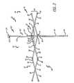
- FIG. 1is an outside elevational view of a corner portion of a framework of a canopy shelter, illustrating the corner brace according to the invention.
- FIG. 2is an inside elevational view of the corner portion of a framework of a canopy shelter of FIG. 1 .
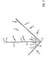
- FIG. 3is a top plan view of the corner portion of the corner portion of a framework of a canopy shelter of FIG. 1 .
- FIG. 4is a side elevational view of the corner portion of a framework of a canopy shelter of FIG. 1 .
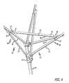
- FIG. 5is an enlarged top outside perspective view of the corner portion of a framework of a canopy shelter of FIG. 1 .
- FIG. 6is an enlarged bottom inside perspective view of the corner portion of a framework of a canopy shelter of FIG. 1 .
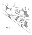
- FIG. 7is an enlarged perspective view of the swivel bracket of the support truss tube member of the corner brace of FIG. 1 .
- FIG. 8is an enlarged perspective view of the support truss end fitting of the support truss tube member of the corner brace of FIG. 1 .
- FIG. 9is an enlarged bottom perspective view of the support truss end fitting of the support truss tube member of the corner brace of FIG. 1 .
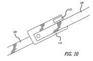
- FIG. 10is an enlarged perspective elevational view of the over-center spacer of the peak beam member of the canopy framework support assembly of the framework of a canopy shelter of FIG. 1 .
- FIG. 11is an enlarged side elevational view of the corner portion shown in FIG. 4 .
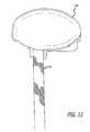
- FIG. 12is an enlarged top perspective view of the central peak hub assembly of the framework of a canopy shelter of FIG. 1 .
- the present inventionaccordingly provides for a corner brace assembly 20 for a framework 22 , only a portion of which is shown, of a quickly erectable canopy shelter, typically including a perimeter truss framework and a central truss framework, which is connected to legs of the canopy shelter to stabilize and support the collapsible shelter, as is described in U.S. Pat. No. 5,490,533, which is incorporated by reference herein.
- the corner brace assemblyis typically provided at a portion of the perimeter framework connected to a leg 24 having upper end 25 and lower end 26 .
- the framework of the canopy shelterpreferably has four legs, but can also have three, five, or more legs.
- a slider member 28is typically slidably mounted to the leg, such as at an upper section of the leg.
- the extendible perimeter assembly 30 of link members connecting legs of the framework togethertypically includes X-shaped outer trusses 32 formed of pairs of link members 34 that are pivotally connected together at pivot point 36 .
- the pairs of link membersinclude first link member 38 and second link member 40 .
- the first link memberhas an outer end 42 pivotally connected to the upper end of a leg, and the second link member having an outer end 44 pivotally connected to the slider member.
- the first and second link membersare thus connected together in a scissors configuration so as to be extendable from a first collapsed position extending horizontally between pairs of legs to a second extended position extending horizontally between the pairs of legs, as is described in U.S. Pat. No. 5,490,533.
- the extendible perimeter assembly of link membersmay also include one or more X-shaped middle trusses 52 not directly connected to the legs, and only supported by the outer trusses.
- the middle trussis similarly formed by a pair of link members 54 pivotally connected together at pivot point 56 , and includes a first link member 58 and a second link member 60 .
- the first link member of the middle trusshas a first end 62 pivotally connected to the inner end of the second link member of the adjacent outer truss
- the second link member of the middle trusshas a first end 64 pivotally connected to the inner end of the first link member of the adjacent outer truss.
- the middle trussis thus similarly formed in a scissors configuration so as to be extendable from a first collapsed position extending horizontally between pairs of legs to a second extended position extending horizontally between the pairs of legs, as is described in U.S. Pat. No. 5,490,533.
- the middle trussmay be connected to another middle truss at their inner ends 66 , or may be connected to another outer truss.
- the corner brace assembly of the present inventionincludes a support truss tube member 70 having a first end 72 and a second end 74 .
- the first end of the support truss tube memberis pivotally connected to a support truss swivel bracket or universal joint 76 that is in turn rotatably connected to an outer section 78 of the first link member of a first outer truss 80 on one side 82 of the leg for rotational movement with respect to the first link member, so that the support truss tube member is capable of pivoting, reciprocal movement and rotational movement with respect to the first link member of the first outer truss 80 .
- the second end of the support truss tube memberincludes a support truss end fitting 84 that is removably connected to an outer section 86 of the first link member of a second outer truss 88 on the other side 90 of the leg.
- the support truss end fittingincludes a slot 92 , such as a T-shaped slot, for receiving a pin or bolt 94 with a correspondingly similar configuration, mounted to and extending from the first link member of the second outer truss, and typically having an enlarged head 96 spaced apart from the second outer truss, allowing the support truss tube member to be rotated to slide the slot of the support truss end fitting over the extending pin on the first link member of the second outer truss, to removably connect the adjacent outer trusses at the leg together when the framework is in the extended configuration as shown.
- a slot 92such as a T-shaped slot
- the support truss tube member of the corner brace assemblymay optionally include a support truss clip 98 adapted to snap fit to one of the link members of the framework when the support truss end fitting is disconnected from the first link member of the second outer truss and the framework of the canopy shelter is to be folded and collapsed, such as for transporting or storing the canopy shelter.
- the canopy shelter frameworkincludes a canopy framework support assembly 100 including a peak beam member 102 having an outer end 104 pivotally mounted to the leg to extend across the shelter and movable between a lowered position (not shown) and a raised, upwardly extending position.
- each of the pole memberstypically comprises an inner peak beam tube section 106 and an outer peak beam tube section 108 that are pivotally joined together through an over-center spacer 110 .
- the over-center spaceradvantageously includes a locking flange 112 allowing the inner peak beam tube section to rotate about the over-center spacer from a collapsed position folded against the outer peak beam tube section to an unfolded, extended position shown in FIG. 10 and braced against the locking flange.
- the canopy framework support assemblymay also include a support strut member 114 with an outer end 116 pivotally mounted to the leg below the peak beam member.
- the support strut memberis pivotally mounted to the slider member.
- the support strut memberhas an inner end 118 with a support bracket 120 pivotally connected to the outer peak beam member to support the peak beam member in a raised, upwardly extending position as shown.
- the inner end 122 of the peak beam memberis pivotally connected to a central peak hub assembly 124 , which is adapted to be connected to a plurality of other peak beam members of the framework of the canopy shelter.
- a canopy cover(not shown) may be placed over the canopy framework support assembly secured to the tops of the legs of the canopy shelter.
Landscapes
- Engineering & Computer Science (AREA)
- Architecture (AREA)
- Civil Engineering (AREA)
- Structural Engineering (AREA)
- Tents Or Canopies (AREA)
- Drilling Tools (AREA)
- Measurement And Recording Of Electrical Phenomena And Electrical Characteristics Of The Living Body (AREA)
- Detergent Compositions (AREA)
Abstract
Description
Claims (1)
Priority Applications (1)
| Application Number | Priority Date | Filing Date | Title |
|---|---|---|---|
| US13/008,792US8091570B2 (en) | 2006-07-14 | 2011-01-18 | Corner brace |
Applications Claiming Priority (4)
| Application Number | Priority Date | Filing Date | Title |
|---|---|---|---|
| US11/486,503US7497227B2 (en) | 2006-07-14 | 2006-07-14 | Corner brace |
| US12/361,429US7673644B2 (en) | 2006-07-14 | 2009-01-28 | Corner brace |
| US12/708,487US7886758B2 (en) | 2006-07-14 | 2010-02-18 | Corner brace |
| US13/008,792US8091570B2 (en) | 2006-07-14 | 2011-01-18 | Corner brace |
Related Parent Applications (1)
| Application Number | Title | Priority Date | Filing Date |
|---|---|---|---|
| US12/708,487ContinuationUS7886758B2 (en) | 2006-07-14 | 2010-02-18 | Corner brace |
Publications (2)
| Publication Number | Publication Date |
|---|---|
| US20110120515A1 US20110120515A1 (en) | 2011-05-26 |
| US8091570B2true US8091570B2 (en) | 2012-01-10 |
Family
ID=38624378
Family Applications (4)
| Application Number | Title | Priority Date | Filing Date |
|---|---|---|---|
| US11/486,503Expired - Fee RelatedUS7497227B2 (en) | 2006-07-14 | 2006-07-14 | Corner brace |
| US12/361,429ActiveUS7673644B2 (en) | 2006-07-14 | 2009-01-28 | Corner brace |
| US12/708,487Expired - Fee RelatedUS7886758B2 (en) | 2006-07-14 | 2010-02-18 | Corner brace |
| US13/008,792ActiveUS8091570B2 (en) | 2006-07-14 | 2011-01-18 | Corner brace |
Family Applications Before (3)
| Application Number | Title | Priority Date | Filing Date |
|---|---|---|---|
| US11/486,503Expired - Fee RelatedUS7497227B2 (en) | 2006-07-14 | 2006-07-14 | Corner brace |
| US12/361,429ActiveUS7673644B2 (en) | 2006-07-14 | 2009-01-28 | Corner brace |
| US12/708,487Expired - Fee RelatedUS7886758B2 (en) | 2006-07-14 | 2010-02-18 | Corner brace |
Country Status (12)
| Country | Link |
|---|---|
| US (4) | US7497227B2 (en) |
| EP (1) | EP2044275B1 (en) |
| JP (1) | JP4897046B2 (en) |
| KR (1) | KR101403306B1 (en) |
| CN (1) | CN101490351B (en) |
| AT (1) | ATE497075T1 (en) |
| AU (1) | AU2007272715B2 (en) |
| BR (1) | BRPI0714414A2 (en) |
| CA (1) | CA2656596C (en) |
| DE (1) | DE602007012255D1 (en) |
| MX (1) | MX2009000435A (en) |
| WO (1) | WO2008008645A1 (en) |
Families Citing this family (8)
| Publication number | Priority date | Publication date | Assignee | Title |
|---|---|---|---|---|
| DE202006014789U1 (en)* | 2006-09-26 | 2008-02-07 | Daas, Kamal | Lattice support structure |
| US20100139725A1 (en)* | 2008-12-09 | 2010-06-10 | Jin-Sheng Lai | Umbrella Having A Detachable Structure |
| US8502182B2 (en)* | 2009-02-06 | 2013-08-06 | Micron Technology, Inc. | Memory device having self-aligned cell structure |
| CN104298040B (en)* | 2014-10-31 | 2018-07-06 | 京东方科技集团股份有限公司 | A kind of COA substrates and preparation method thereof and display device |
| JP6577288B2 (en)* | 2015-08-19 | 2019-09-18 | 大川工業株式会社 | Frame for portable awning |
| CN111082227B (en)* | 2019-12-31 | 2021-11-05 | 河南爱科瑞特电子科技有限公司 | Vehicle-mounted self-unfolding logarithmic period antenna and use method |
| USD1030094S1 (en)* | 2021-03-30 | 2024-06-04 | Mark Andrew Fraser | Collapsible shelter |
| USD1097037S1 (en)* | 2024-12-13 | 2025-10-07 | Xin Qiu | Canopy |
Citations (45)
| Publication number | Priority date | Publication date | Assignee | Title |
|---|---|---|---|---|
| US306011A (en)* | 1884-09-30 | And john i | ||
| US514726A (en)* | 1894-02-13 | John w | ||
| US1170188A (en) | 1915-04-26 | 1916-02-01 | Gold Medal Camp Furniture Mfg Co | Folding frame for portable buildings. |
| US1204329A (en) | 1916-05-01 | 1916-11-07 | John E Wilkins | Collapsible tent-frame. |
| US1712836A (en) | 1927-11-19 | 1929-05-14 | Mills August | Combination bed and tent |
| US1846011A (en) | 1929-10-05 | 1932-02-23 | Judson J Adams | Tent |
| US1853367A (en) | 1931-04-22 | 1932-04-12 | Ralph M Reeves | Collapsible tent frame |
| US2151908A (en) | 1938-04-21 | 1939-03-28 | Max E Gottlieb | Chapel tent |
| US2845292A (en) | 1956-02-21 | 1958-07-29 | Nielsen | Brace locking device |
| US3890989A (en)* | 1973-11-23 | 1975-06-24 | Benjamin Kuxhouse | Canopy supporting frame and canopy |
| US3942904A (en) | 1974-04-19 | 1976-03-09 | Kathet Corporation | Telescopically and circumferentially adjustable brace |
| US4201237A (en) | 1978-10-10 | 1980-05-06 | Crawford Lynn D | Pivotal frame structure for collapsible umbrella type tent |
| US4407317A (en) | 1981-03-16 | 1983-10-04 | Melvin Crandall | Umbrella reversal prevention structure |
| US4558713A (en) | 1982-10-29 | 1985-12-17 | American Canvas Company | Frame system and connectors for portable shelters |
| US4601301A (en) | 1985-06-19 | 1986-07-22 | Terry Hermanson | Umbrella with lazy tong structure |
| US4607656A (en) | 1983-09-26 | 1986-08-26 | Carter Mark C | Quick erection collapsible shelter |
| US4641676A (en) | 1984-01-23 | 1987-02-10 | Lynch James P | Collapsible canopy structure |
| US4779635A (en) | 1987-08-26 | 1988-10-25 | Lynch James P | Collapsible canopy with telescoping roof support structure |
| US4947884A (en) | 1989-05-24 | 1990-08-14 | Lynch James P | Collapsible canopy with auto erect roof support structure |
| US5022420A (en) | 1990-07-19 | 1991-06-11 | Brim Walter L | Lawn mower shade apparatus |
| US5035253A (en) | 1989-10-30 | 1991-07-30 | Bortles Allan D | Tent canopy rain awning |
| GB2258475A (en) | 1991-08-09 | 1993-02-10 | Tsai Ming Liang | Folding tent |
| WO1993013284A1 (en) | 1991-12-23 | 1993-07-08 | World Shelters, Inc. | Polyhedron building system having telescoping scissors |
| US5244001A (en) | 1991-01-04 | 1993-09-14 | Lynch James P | Collapsible canopy framework having captured scissor ends with non-compressive pivots |
| JPH06299735A (en) | 1993-04-15 | 1994-10-25 | Shiyuunan Chiiki Jiba Sangyo Shinko Center | Common frame for hammock and tent, completed hammock and completed tent |
| US5638853A (en) | 1996-03-07 | 1997-06-17 | Tsai; Tony M. L. | Tent structure |
| US5701923A (en) | 1996-03-07 | 1997-12-30 | Losi, Jr.; Raymond | Collapsible shelter |
| GB2320509A (en) | 1996-12-19 | 1998-06-24 | Kingfisher Lighting Limited | Collapsible portable shelter |
| US5771651A (en) | 1995-11-29 | 1998-06-30 | Shiina; Takaaki | Framework for small-scale building |
| JPH1162323A (en) | 1997-08-22 | 1999-03-05 | Shinsei:Kk | Open-close type tent |
| US5944040A (en) | 1997-05-23 | 1999-08-31 | Jang; Jung-Woo | Collapsible tent frame |
| US6173726B1 (en)* | 1998-12-09 | 2001-01-16 | Fiskars Inc. | Erectable shelter including a collapsible truss |
| EP1138852A2 (en) | 2000-03-30 | 2001-10-04 | Sven Melker Nilsson | Arrangement for a tent |
| US20020092555A1 (en) | 2001-01-16 | 2002-07-18 | Ting-Hsing Chen | Reinforcement structure for sun tent extension canopy |
| US20020189659A1 (en) | 1994-07-25 | 2002-12-19 | Carter Mark C. | Erectable canopy with reinforced roof structure |
| JP2003227249A (en) | 2002-02-01 | 2003-08-15 | Newtec Japan Co Ltd | Collapsible tent |
| US6651942B1 (en) | 2001-08-10 | 2003-11-25 | Kevin S. Yardley | Collapsible device for supporting a disposable plastic bag |
| US6772780B2 (en) | 2002-03-04 | 2004-08-10 | Roy Justin Price | Collapsible frame |
| US6779538B2 (en) | 2000-09-07 | 2004-08-24 | Gale Pacific Limited | Erectable, collapsible shelter |
| US20050016573A1 (en) | 2003-07-24 | 2005-01-27 | Weidan Wu | Portable collapsible tent |
| US6848461B2 (en) | 2003-01-23 | 2005-02-01 | Tony Tsai | Tent structure |
| JP2005290837A (en) | 2004-03-31 | 2005-10-20 | Kudoo Kk | Frame structure of foldable tent |
| US7168439B2 (en) | 2003-09-12 | 2007-01-30 | North Pole Limited | Collapsible gazebo frame with independent canopy support |
| US20070221263A1 (en) | 2006-03-22 | 2007-09-27 | Chia-Shu Tai | Reinforcement device of folding tent |
| US7367348B2 (en) | 2006-03-21 | 2008-05-06 | Ming-Liang Tsai | Collapsible tent structure |
Family Cites Families (5)
| Publication number | Priority date | Publication date | Assignee | Title |
|---|---|---|---|---|
| US2135961A (en)* | 1936-10-22 | 1938-11-08 | Elijah P Chenoweth | Tent frame |
| JP2526299Y2 (en)* | 1990-03-23 | 1997-02-19 | 日産ディーゼル工業株式会社 | Exhaust gas splitter |
| US5902195A (en)* | 1994-12-12 | 1999-05-11 | Pavonetti; Onofrio F. | Collapsible/portable soccer goal |
| KR20020062530A (en)* | 2001-01-22 | 2002-07-26 | 한주환 | Folding tent frame |
| KR20020018687A (en) | 2002-01-08 | 2002-03-08 | 김대환 | Structure of canopy |
- 2006
- 2006-07-14USUS11/486,503patent/US7497227B2/ennot_activeExpired - Fee Related
- 2007
- 2007-06-29JPJP2009520880Apatent/JP4897046B2/ennot_activeExpired - Fee Related
- 2007-06-29KRKR1020097002943Apatent/KR101403306B1/ennot_activeExpired - Fee Related
- 2007-06-29CACA2656596Apatent/CA2656596C/ennot_activeExpired - Fee Related
- 2007-06-29ATAT07799182Tpatent/ATE497075T1/ennot_activeIP Right Cessation
- 2007-06-29WOPCT/US2007/072482patent/WO2008008645A1/enactiveApplication Filing
- 2007-06-29EPEP07799182Apatent/EP2044275B1/ennot_activeNot-in-force
- 2007-06-29CNCN2007800266874Apatent/CN101490351B/ennot_activeExpired - Fee Related
- 2007-06-29MXMX2009000435Apatent/MX2009000435A/enactiveIP Right Grant
- 2007-06-29DEDE602007012255Tpatent/DE602007012255D1/enactiveActive
- 2007-06-29AUAU2007272715Apatent/AU2007272715B2/ennot_activeCeased
- 2007-06-29BRBRPI0714414-8A2Apatent/BRPI0714414A2/ennot_activeApplication Discontinuation
- 2009
- 2009-01-28USUS12/361,429patent/US7673644B2/enactiveActive
- 2010
- 2010-02-18USUS12/708,487patent/US7886758B2/ennot_activeExpired - Fee Related
- 2011
- 2011-01-18USUS13/008,792patent/US8091570B2/enactiveActive
Patent Citations (50)
| Publication number | Priority date | Publication date | Assignee | Title |
|---|---|---|---|---|
| US306011A (en)* | 1884-09-30 | And john i | ||
| US514726A (en)* | 1894-02-13 | John w | ||
| US1170188A (en) | 1915-04-26 | 1916-02-01 | Gold Medal Camp Furniture Mfg Co | Folding frame for portable buildings. |
| US1204329A (en) | 1916-05-01 | 1916-11-07 | John E Wilkins | Collapsible tent-frame. |
| US1712836A (en) | 1927-11-19 | 1929-05-14 | Mills August | Combination bed and tent |
| US1846011A (en) | 1929-10-05 | 1932-02-23 | Judson J Adams | Tent |
| US1853367A (en) | 1931-04-22 | 1932-04-12 | Ralph M Reeves | Collapsible tent frame |
| US2151908A (en) | 1938-04-21 | 1939-03-28 | Max E Gottlieb | Chapel tent |
| US2845292A (en) | 1956-02-21 | 1958-07-29 | Nielsen | Brace locking device |
| US3890989A (en)* | 1973-11-23 | 1975-06-24 | Benjamin Kuxhouse | Canopy supporting frame and canopy |
| US3942904A (en) | 1974-04-19 | 1976-03-09 | Kathet Corporation | Telescopically and circumferentially adjustable brace |
| US4201237A (en) | 1978-10-10 | 1980-05-06 | Crawford Lynn D | Pivotal frame structure for collapsible umbrella type tent |
| US4407317A (en) | 1981-03-16 | 1983-10-04 | Melvin Crandall | Umbrella reversal prevention structure |
| US4558713A (en) | 1982-10-29 | 1985-12-17 | American Canvas Company | Frame system and connectors for portable shelters |
| US4607656A (en) | 1983-09-26 | 1986-08-26 | Carter Mark C | Quick erection collapsible shelter |
| US4641676A (en) | 1984-01-23 | 1987-02-10 | Lynch James P | Collapsible canopy structure |
| US4601301A (en) | 1985-06-19 | 1986-07-22 | Terry Hermanson | Umbrella with lazy tong structure |
| US4779635A (en) | 1987-08-26 | 1988-10-25 | Lynch James P | Collapsible canopy with telescoping roof support structure |
| US4947884A (en) | 1989-05-24 | 1990-08-14 | Lynch James P | Collapsible canopy with auto erect roof support structure |
| US5035253A (en) | 1989-10-30 | 1991-07-30 | Bortles Allan D | Tent canopy rain awning |
| US5022420A (en) | 1990-07-19 | 1991-06-11 | Brim Walter L | Lawn mower shade apparatus |
| US5244001A (en) | 1991-01-04 | 1993-09-14 | Lynch James P | Collapsible canopy framework having captured scissor ends with non-compressive pivots |
| US5275188A (en) | 1991-08-09 | 1994-01-04 | Tsai Ming L | Modified folding tent |
| GB2258475A (en) | 1991-08-09 | 1993-02-10 | Tsai Ming Liang | Folding tent |
| WO1993013284A1 (en) | 1991-12-23 | 1993-07-08 | World Shelters, Inc. | Polyhedron building system having telescoping scissors |
| US5274980A (en) | 1991-12-23 | 1994-01-04 | World Shelters, Inc. | Polyhedron building system having telescoping scissors |
| JPH06299735A (en) | 1993-04-15 | 1994-10-25 | Shiyuunan Chiiki Jiba Sangyo Shinko Center | Common frame for hammock and tent, completed hammock and completed tent |
| US6601599B2 (en) | 1994-07-25 | 2003-08-05 | Mark C. Carter | Erectable canopy with reinforced roof structure |
| US20020189659A1 (en) | 1994-07-25 | 2002-12-19 | Carter Mark C. | Erectable canopy with reinforced roof structure |
| US6874520B2 (en) | 1994-07-25 | 2005-04-05 | Mark C. Carter | Erectable canopy with reinforced roof structure |
| US5771651A (en) | 1995-11-29 | 1998-06-30 | Shiina; Takaaki | Framework for small-scale building |
| US5638853A (en) | 1996-03-07 | 1997-06-17 | Tsai; Tony M. L. | Tent structure |
| US5701923A (en) | 1996-03-07 | 1997-12-30 | Losi, Jr.; Raymond | Collapsible shelter |
| US6035877A (en) | 1996-03-07 | 2000-03-14 | Losi, Jr.; Raymond | Collapsible shelter |
| GB2320509A (en) | 1996-12-19 | 1998-06-24 | Kingfisher Lighting Limited | Collapsible portable shelter |
| US5944040A (en) | 1997-05-23 | 1999-08-31 | Jang; Jung-Woo | Collapsible tent frame |
| JPH1162323A (en) | 1997-08-22 | 1999-03-05 | Shinsei:Kk | Open-close type tent |
| US6173726B1 (en)* | 1998-12-09 | 2001-01-16 | Fiskars Inc. | Erectable shelter including a collapsible truss |
| EP1138852A2 (en) | 2000-03-30 | 2001-10-04 | Sven Melker Nilsson | Arrangement for a tent |
| US6779538B2 (en) | 2000-09-07 | 2004-08-24 | Gale Pacific Limited | Erectable, collapsible shelter |
| US20020092555A1 (en) | 2001-01-16 | 2002-07-18 | Ting-Hsing Chen | Reinforcement structure for sun tent extension canopy |
| US6651942B1 (en) | 2001-08-10 | 2003-11-25 | Kevin S. Yardley | Collapsible device for supporting a disposable plastic bag |
| JP2003227249A (en) | 2002-02-01 | 2003-08-15 | Newtec Japan Co Ltd | Collapsible tent |
| US6772780B2 (en) | 2002-03-04 | 2004-08-10 | Roy Justin Price | Collapsible frame |
| US6848461B2 (en) | 2003-01-23 | 2005-02-01 | Tony Tsai | Tent structure |
| US20050016573A1 (en) | 2003-07-24 | 2005-01-27 | Weidan Wu | Portable collapsible tent |
| US7168439B2 (en) | 2003-09-12 | 2007-01-30 | North Pole Limited | Collapsible gazebo frame with independent canopy support |
| JP2005290837A (en) | 2004-03-31 | 2005-10-20 | Kudoo Kk | Frame structure of foldable tent |
| US7367348B2 (en) | 2006-03-21 | 2008-05-06 | Ming-Liang Tsai | Collapsible tent structure |
| US20070221263A1 (en) | 2006-03-22 | 2007-09-27 | Chia-Shu Tai | Reinforcement device of folding tent |
Also Published As
| Publication number | Publication date |
|---|---|
| AU2007272715A1 (en) | 2008-01-17 |
| US20090126770A1 (en) | 2009-05-21 |
| MX2009000435A (en) | 2009-01-29 |
| CN101490351B (en) | 2010-12-29 |
| CN101490351A (en) | 2009-07-22 |
| JP2009543962A (en) | 2009-12-10 |
| US20080011346A1 (en) | 2008-01-17 |
| KR101403306B1 (en) | 2014-06-05 |
| US20110120515A1 (en) | 2011-05-26 |
| US7886758B2 (en) | 2011-02-15 |
| US20100147346A1 (en) | 2010-06-17 |
| ATE497075T1 (en) | 2011-02-15 |
| EP2044275B1 (en) | 2011-01-26 |
| CA2656596A1 (en) | 2008-01-17 |
| US7673644B2 (en) | 2010-03-09 |
| AU2007272715B2 (en) | 2012-05-17 |
| KR20090033895A (en) | 2009-04-06 |
| WO2008008645A1 (en) | 2008-01-17 |
| DE602007012255D1 (en) | 2011-03-10 |
| JP4897046B2 (en) | 2012-03-14 |
| CA2656596C (en) | 2014-06-17 |
| EP2044275A1 (en) | 2009-04-08 |
| US7497227B2 (en) | 2009-03-03 |
| BRPI0714414A2 (en) | 2013-10-29 |
Similar Documents
| Publication | Publication Date | Title |
|---|---|---|
| US6382224B1 (en) | Erectable canopy with reinforced roof structure | |
| US7624747B2 (en) | Erectable canopy with reinforced roof structure | |
| US7530364B2 (en) | Erectable canopy with reinforced roof structure | |
| US8091570B2 (en) | Corner brace | |
| CA2494926C (en) | Erectable canopy with reinforced roof structure |
Legal Events
| Date | Code | Title | Description |
|---|---|---|---|
| STCF | Information on status: patent grant | Free format text:PATENTED CASE | |
| FPAY | Fee payment | Year of fee payment:4 | |
| AS | Assignment | Owner name:INTERNATIONAL E-Z UP, INC., CALIFORNIA Free format text:ASSIGNMENT OF ASSIGNORS INTEREST;ASSIGNOR:CARTER, MARK C.;REEL/FRAME:049334/0981 Effective date:20190521 | |
| AS | Assignment | Owner name:LBC CREDIT AGENCY SERVICES, LLC, AS AGENT, PENNSYL Free format text:SECURITY INTEREST;ASSIGNOR:INTERNATIONAL E-Z UP, INC.;REEL/FRAME:049344/0017 Effective date:20190531 Owner name:LBC CREDIT AGENCY SERVICES, LLC, AS AGENT, PENNSYLVANIA Free format text:SECURITY INTEREST;ASSIGNOR:INTERNATIONAL E-Z UP, INC.;REEL/FRAME:049344/0017 Effective date:20190531 | |
| MAFP | Maintenance fee payment | Free format text:PAYMENT OF MAINTENANCE FEE, 8TH YR, SMALL ENTITY (ORIGINAL EVENT CODE: M2552); ENTITY STATUS OF PATENT OWNER: SMALL ENTITY Year of fee payment:8 | |
| AS | Assignment | Owner name:JPMORGAN CHASE BANK, N.A., AS ADMINISTRATIVE AGENT, ILLINOIS Free format text:SECURITY INTEREST;ASSIGNOR:INTERNATIONAL E-Z UP, INC.;REEL/FRAME:060818/0784 Effective date:20220722 | |
| AS | Assignment | Owner name:INTERNATIONAL E-Z UP, INC., CALIFORNIA Free format text:RELEASE BY SECURED PARTY;ASSIGNOR:LBC CREDIT AGENCY SERVICES, LLC, AS AGENT;REEL/FRAME:060918/0053 Effective date:20220722 | |
| MAFP | Maintenance fee payment | Free format text:PAYMENT OF MAINTENANCE FEE, 12TH YR, SMALL ENTITY (ORIGINAL EVENT CODE: M2553); ENTITY STATUS OF PATENT OWNER: SMALL ENTITY Year of fee payment:12 |