US8090478B2 - Control for pressurized bladder in a patient support apparatus - Google Patents
Control for pressurized bladder in a patient support apparatusDownload PDFInfo
- Publication number
- US8090478B2 US8090478B2US11/916,766US91676606AUS8090478B2US 8090478 B2US8090478 B2US 8090478B2US 91676606 AUS91676606 AUS 91676606AUS 8090478 B2US8090478 B2US 8090478B2
- Authority
- US
- United States
- Prior art keywords
- pressure
- bladder
- patient
- patient support
- acceptable range
- Prior art date
- Legal status (The legal status is an assumption and is not a legal conclusion. Google has not performed a legal analysis and makes no representation as to the accuracy of the status listed.)
- Active, expires
Links
- 239000012530fluidSubstances0.000claimsabstractdescription175
- 238000000034methodMethods0.000claimsdescription20
- 230000008859changeEffects0.000claimsdescription17
- 238000004891communicationMethods0.000claimsdescription17
- 230000001105regulatory effectEffects0.000claimsdescription16
- 238000001514detection methodMethods0.000claimsdescription6
- 238000012544monitoring processMethods0.000claimsdescription4
- 230000004913activationEffects0.000claimsdescription2
- 239000003570airSubstances0.000description31
- XLYOFNOQVPJJNP-UHFFFAOYSA-NwaterSubstancesOXLYOFNOQVPJJNP-UHFFFAOYSA-N0.000description27
- 230000000977initiatory effectEffects0.000description8
- 239000006260foamSubstances0.000description5
- 230000008569processEffects0.000description4
- 230000003466anti-cipated effectEffects0.000description3
- 210000004197pelvisAnatomy0.000description3
- 230000009471actionEffects0.000description2
- 210000004712air sacAnatomy0.000description2
- 230000003111delayed effectEffects0.000description2
- 210000002414legAnatomy0.000description2
- 230000007246mechanismEffects0.000description2
- 230000004044responseEffects0.000description2
- 230000001225therapeutic effectEffects0.000description2
- 210000000689upper legAnatomy0.000description2
- 238000013022ventingMethods0.000description2
- 238000012935AveragingMethods0.000description1
- 208000004210Pressure UlcerDiseases0.000description1
- 230000006978adaptationEffects0.000description1
- 239000012080ambient airSubstances0.000description1
- 230000000712assemblyEffects0.000description1
- 238000000429assemblyMethods0.000description1
- 230000009286beneficial effectEffects0.000description1
- 230000015572biosynthetic processEffects0.000description1
- 238000004364calculation methodMethods0.000description1
- 244000309466calfSpecies0.000description1
- 238000004140cleaningMethods0.000description1
- 238000010276constructionMethods0.000description1
- 230000008602contractionEffects0.000description1
- 230000001276controlling effectEffects0.000description1
- 238000012937correctionMethods0.000description1
- 230000002596correlated effectEffects0.000description1
- 230000003247decreasing effectEffects0.000description1
- 230000001934delayEffects0.000description1
- 238000013461designMethods0.000description1
- 238000010586diagramMethods0.000description1
- 238000009429electrical wiringMethods0.000description1
- 239000007788liquidSubstances0.000description1
- 238000012423maintenanceMethods0.000description1
- 238000004519manufacturing processMethods0.000description1
- 235000012054mealsNutrition0.000description1
- 230000000474nursing effectEffects0.000description1
- 238000004091panningMethods0.000description1
- 230000001960triggered effectEffects0.000description1
Images


Classifications
- A—HUMAN NECESSITIES
- A47—FURNITURE; DOMESTIC ARTICLES OR APPLIANCES; COFFEE MILLS; SPICE MILLS; SUCTION CLEANERS IN GENERAL
- A47C—CHAIRS; SOFAS; BEDS
- A47C27/00—Spring, stuffed or fluid mattresses or cushions specially adapted for chairs, beds or sofas
- A47C27/08—Fluid mattresses
- A—HUMAN NECESSITIES
- A61—MEDICAL OR VETERINARY SCIENCE; HYGIENE
- A61G—TRANSPORT, PERSONAL CONVEYANCES, OR ACCOMMODATION SPECIALLY ADAPTED FOR PATIENTS OR DISABLED PERSONS; OPERATING TABLES OR CHAIRS; CHAIRS FOR DENTISTRY; FUNERAL DEVICES
- A61G7/00—Beds specially adapted for nursing; Devices for lifting patients or disabled persons
- A61G7/05—Parts, details or accessories of beds
- A61G7/057—Arrangements for preventing bed-sores or for supporting patients with burns, e.g. mattresses specially adapted therefor
- A61G7/05769—Arrangements for preventing bed-sores or for supporting patients with burns, e.g. mattresses specially adapted therefor with inflatable chambers
- A—HUMAN NECESSITIES
- A61—MEDICAL OR VETERINARY SCIENCE; HYGIENE
- A61G—TRANSPORT, PERSONAL CONVEYANCES, OR ACCOMMODATION SPECIALLY ADAPTED FOR PATIENTS OR DISABLED PERSONS; OPERATING TABLES OR CHAIRS; CHAIRS FOR DENTISTRY; FUNERAL DEVICES
- A61G2203/00—General characteristics of devices
- A61G2203/30—General characteristics of devices characterised by sensor means
- A61G2203/34—General characteristics of devices characterised by sensor means for pressure
- A—HUMAN NECESSITIES
- A61—MEDICAL OR VETERINARY SCIENCE; HYGIENE
- A61G—TRANSPORT, PERSONAL CONVEYANCES, OR ACCOMMODATION SPECIALLY ADAPTED FOR PATIENTS OR DISABLED PERSONS; OPERATING TABLES OR CHAIRS; CHAIRS FOR DENTISTRY; FUNERAL DEVICES
- A61G2203/00—General characteristics of devices
- A61G2203/30—General characteristics of devices characterised by sensor means
- A61G2203/42—General characteristics of devices characterised by sensor means for inclination
- Y—GENERAL TAGGING OF NEW TECHNOLOGICAL DEVELOPMENTS; GENERAL TAGGING OF CROSS-SECTIONAL TECHNOLOGIES SPANNING OVER SEVERAL SECTIONS OF THE IPC; TECHNICAL SUBJECTS COVERED BY FORMER USPC CROSS-REFERENCE ART COLLECTIONS [XRACs] AND DIGESTS
- Y10—TECHNICAL SUBJECTS COVERED BY FORMER USPC
- Y10T—TECHNICAL SUBJECTS COVERED BY FORMER US CLASSIFICATION
- Y10T137/00—Fluid handling
- Y10T137/8593—Systems
- Y10T137/85978—With pump
- Y10T137/86035—Combined with fluid receiver
- Y—GENERAL TAGGING OF NEW TECHNOLOGICAL DEVELOPMENTS; GENERAL TAGGING OF CROSS-SECTIONAL TECHNOLOGIES SPANNING OVER SEVERAL SECTIONS OF THE IPC; TECHNICAL SUBJECTS COVERED BY FORMER USPC CROSS-REFERENCE ART COLLECTIONS [XRACs] AND DIGESTS
- Y10—TECHNICAL SUBJECTS COVERED BY FORMER USPC
- Y10T—TECHNICAL SUBJECTS COVERED BY FORMER US CLASSIFICATION
- Y10T137/00—Fluid handling
- Y10T137/8593—Systems
- Y10T137/86389—Programmer or timer
Definitions
- the present inventionrelates to patient support surfaces which include a pressurized bladder and a controller for regulating the pressure of the bladder.
- These mattressesmay be powered mattresses wherein the pressure in the air bladders is actively regulated.
- some powered systemsinclude a controller which receives a signal from pressure sensors and controls the operation of an air supply to regulate the pressure within the bladders of the air mattress.
- One embodiment of the inventiontakes the form of an apparatus for supporting a patient that includes a patient support surface, at least one fluid containing bladder and a pressure control assembly.
- the at least one bladderis positioned to provide support for the patient when the patient is bearing on the patient support surface for at least a portion of the patient support surface.
- the pressure control assemblyis operably coupled with the at least one bladder and regulates the fluid pressure within the at least one bladder.
- the pressure control assemblyincludes a programmable controller which is programmed to monitor sensed pressure values of the fluid pressure within the at least one bladder and adjust the fluid pressure within the at least one bladder.
- the controlleris programmed wherein an acceptable range of pressure values is defined and the controller initiates adjustment of the fluid pressure within the at least one bladder when a sensed value is located outside the acceptable range of pressure and a time period following the sensing of the sensed value has elapsed without the fluid pressure within the at least one bladder returning to the acceptable range of pressure, where the time period has a variable length.
- the first bladdermay support the head and/or upper torso of a patient lying on the patient support surface while the second bladder supports the pelvic region of the same patient.
- the time periodmay have a length that is a function of the difference between the sensed value and the acceptable range of pressure.
- the time periodmay have a length that is determined by a selected one of a plurality of different algorithms. Selection of the selected one algorithm may be a function of the difference between the sensed value and the acceptable range of pressure.
- a first algorithmmay be selected when the difference between the sensed value and the acceptable range of pressure does not exceed a first window value.
- a second algorithmmay be selected when the difference between the sensed value and the acceptable range of pressure exceeds the first window value, where the time periods determined by the first algorithm have a first maximum value and the time periods determined by the second algorithm have a second maximum value. The first maximum value may be greater than the second maximum value.
- the time periods determined by the first algorithmmay have a variable length and the time periods determined by the second algorithm may have a substantially invariable length.
- the second algorithmmay initiate adjustment of the fluid pressure within the at least one bladder substantially immediately after determining that the difference between the sensed value and the acceptable range of pressure exceeds the first window value.
- the time periods determined by the first algorithmmay be a function of the stability of the sensed pressure values.
- the stability of the sensed pressure valuesmay be a function of a difference between a first variable representative of a current sensed pressure value and a second variable representative of a moving average of a most recent set of the sensed pressure values.
- the time periodsmay include time periods that are a function of the stability of the sensed pressure values.
- the stability of the sensed pressure valuesmay be a function of a difference between a first variable representative of a current sensed pressure value and a second variable representative of a moving average of a most recent set of the sensed pressure values.
- the difference between the first variable and the second variablemay be less than or equal to a predetermined maximum value for a predetermined time period.
- the controllermay initiate adjustment of the fluid pressure within the least one bladder after the time period elapses.
- the predetermined maximum valuemay correspond to a pressure difference of approximately 0.5 inches of water in the at least one bladder and the predetermined time period may be at least as great as approximately 30 seconds.
- the acceptable range of pressuremay be variable and the controller may calculate the acceptable range of pressure values as a function of the weight of the patient.
- the patient support surfacemay be an articulating surface having a plurality of configurations.
- the acceptable range of pressuremay be variable and the controller may calculate the acceptable range of pressures as a function of the configuration of the patient support surface.
- the pressure control assemblymay include a compressor in selective fluid communication with the at least one bladder.
- the compressormay controllably communicate fluid under pressure to the at least one bladder to thereby selectively adjust the fluid pressure within the at least one bladder.
- the pressure control assemblymay further include at least one valve for regulating a fluid flow in communication with the at least one bladder, where operation of the at least one valve is controlled by the controller.
- the controllermay define a sleep mode method of operation, where activation of the sleep mode increases the size of the acceptable range of pressure values.
- the controllermay remain in the sleep mode after adjustment of the fluid pressure.
- the patient supportmay include a first fluid containing bladder, which may be disposed proximate the head end of the patient support surface and positioned to provide support for the patient when the patient is bearing on a portion of the patient support proximate the head end, as well as a second fluid containing bladder, which may be disposed substantially centrally between the head end and the foot end of the patient support and positioned to provide support for the patient when the patient is bearing on a portion of the patient support proximate a midpoint between the head end and the foot end.
- the pressure control assemblymay be operably coupled with the first and second bladders and may regulate a first fluid pressure in the first bladder and a second fluid pressure in the second bladder.
- the pressure control assemblymay include a programmable controller, which may be programmed to monitor sensed pressure values of the first and second fluid pressures and separately adjust the first and second fluid pressures, where an acceptable range of pressure values is determined for each of the first and second bladders and the controller initiates adjustment of one of the first and second fluid pressures when one of the sensed pressure values is located outside the respective one of the acceptable ranges of pressure values and a time period following the sensing of the sensed value has elapsed without the fluid pressure within the respective one of the first and second bladders returning to the respective one of the acceptable ranges of pressure values.
- the time periodmay have a variable length.
- the patient supportmay further include a third fluid containing bladder disposed proximate the foot end of the patient support and positioned to provide support for the patient when the patient is bearing on a portion of the patient support proximate the foot end, where the pressure control assembly is operably coupled to the third bladder and regulates a third fluid pressure in the third bladder, the controller is programmed to monitor sensed pressure values of the third fluid pressure and independently adjust the third fluid pressure, where a third acceptable range of pressure values is determined for the third bladder and the controller initiates adjustment of the third fluid pressure when one of the sensed third fluid pressure values is located outside the third acceptable range of pressure values and a third time period following the sensing of the sensed value has elapsed without the fluid pressure within the third bladder returning to the third acceptable range of pressure values.
- the third time periodmay have a variable length.
- the patient supportmay include an articulating surface and may include a first section disposed proximate the head end, a second section disposed in a central portion of the patient support surface and a third section disposed proximate the foot end, the first, second and third sections being relatively articulatable, where the first bladder is disposed in the first section, the second bladder is disposed in the second section and the third bladder is disposed in the third section.
- the acceptable ranges of pressure values for the first and second bladdersmay be a function of the weight of the patient and/or a function of a position of the first section.
- the third acceptable range of pressure valuesmay be a function of the weight of the patient.
- the third rangemay or may not vary with changes in the position of the first section.
- the patient supportmay include a weight sensing device operably coupled with the controller and the acceptable range of pressure values for each of the first and second bladders may be a function of the weight of the patient.
- the first section of the patient supportmay be angularly repositionable relative to the second section.
- the controllermay initiate inflation of the second bladder to a value above the respective acceptable range of pressure values and return the second bladder to the respective acceptable range of pressure values upon detection of movement of the first section through a predefined angular amount.
- the first sectionmay be generally pivotable about a substantially horizontal axis and may be pivotally raised and lowered about the horizontal axis.
- the predefined angular amountmay be non-directional with respect to the pivotal raising and the lowering of the first section about the horizontal axis. In one embodiment, the predefined angular amount may be no greater than an angular rotation of approximately 3 degrees about the horizontal axis.
- the acceptable range of pressure values for the second bladdermay be a function of the position of the first section of the articulating patient support surface and the controller initiated inflation may occur when movement of the first section results in a change in the acceptable range of pressure values for the second bladder.
- the acceptable range of pressure values for the second bladdermay be a function of the position of the first section of the articulating patient support surface and the predefined angular amount may be sized where the controller initiated inflation is occurable without a change in the acceptable range of pressure values for the second bladder.
- the acceptable ranges of pressure values for the first and second bladdersmay define different ranges.
- a first algorithmmay be selected when the difference between the sensed value and the acceptable range of pressure does not exceed a first window value and a second algorithm may be selected when the difference between the sensed value and the acceptable range of pressure exceeds the first window value.
- the time periods determined by the first algorithmsmay have a first maximum value and the time periods determined by the second algorithms may have a second maximum value.
- the first maximum valuesmay be greater than the second maximum values.
- the first maximum valuesmay be at least as great as approximately 10 minutes.
- the time periods determined by the first algorithmsmay have a variable length and the second algorithms may initiate adjustment of the respective one of the first and second fluid pressures substantially immediately after determining that the difference between the sensed value and the respective acceptable rang of pressure exceeds the respective first window value.
- the patient support surfacemay be an articulating surface and includes a first section disposed proximate the head end and a second section disposed in a central portion of the patient support surface, the first and second sections being relatively articulatable and wherein the first bladder is disposed in the first section and the second bladder is disposed in the second section.
- the acceptable range of pressure values for the second bladdermay be a function of the position of the first section of the articulating patient support surface.
- the acceptable range of pressure values for each of the first and second bladdersis a function of the position of the first section of the articulating patient support surface.
- the pressure control assemblymay include a compressor in selective fluid communication with the first and second bladders, the compressor controllably communicating fluid under pressure to the first and second bladders to thereby selectively increase the fluid pressure within the first and second bladders.
- the pressure control assemblymay further include at least one valve for regulating a fluid flow in communication with the first and second bladders, operation of the at least one valve being controlled by the controller.
- the controllermay define a sleep mode method of operation wherein the sleep mode increases the size of the acceptable ranges of pressure values. The controller may remain in the sleep mode after adjustment of a respective one of the fluid pressures.
- Another embodiment of the inventiontakes the form of a method of supporting a patient.
- the methodincludes providing at least one fluid containing bladder to support at least a portion of the weight of the patient, monitoring the fluid pressure within the at least one bladder, and regulating the fluid pressure within the at least one bladder by defining an acceptable range of fluid pressures and adjusting the fluid pressure within the at least one bladder only when a fluid pressure value has been detected outside the acceptable range of fluid pressures and a time period following the detection of the fluid pressure value has elapsed without the fluid pressure within the at least one bladder returning to the acceptable range of fluid pressure values, the time period having a variable length.
- the time periodmay have a length that is a function of the difference between the fluid pressure value and the acceptable range of fluid pressure values.
- the time periodmay have a length that is determined by a selected one of a plurality of different algorithms. Selection of the selected one algorithm may be a function of the difference between the fluid pressure value and the acceptable range of fluid pressure values.
- a first algorithmmay be selected when the difference between the fluid pressure value and the acceptable range of fluid pressure values does not exceed a first window value.
- a second algorithmmay be selected when the difference between the fluid pressure value and the acceptable range of fluid pressure values exceeds the first window value, where the time periods determined by the first algorithm have a first maximum value and the time periods determined by the second algorithm have a second maximum value. The first maximum value may be greater than the second maximum value.
- the time periods determined by the first algorithmmay have a variable length and the time periods determined by the second algorithm may have a substantially invariable length.
- the second algorithmmay initiate adjustment of the fluid pressure within the bladder substantially immediately after determining that the difference between the fluid pressure value and the acceptable range of fluid pressure values exceeds the first window value.
- the time periods determined by the first algorithmmay be a function of the stability of the monitored fluid pressure values.
- the stability of the monitored fluid pressure valuesmay be a function of a difference between a first variable representative of a current monitored fluid pressure value and a second variable representative of a moving average of a most recent set of the monitored fluid pressure values.
- the difference between the first variable and the second variablemay be less than or equal to a predetermined maximum value for a predetermined time period.
- the controllermay initiate adjustment of the fluid pressure within the bladder after the time period elapses.
- the predetermined maximum valuemay correspond to a pressure difference of approximately 0.5 inches of water in the bladder and the predetermined time period may be at least as great as approximately 30 seconds.
- Still another embodiment of the inventiontakes the form of a pressure control assembly to regulate a fluid pressure in a bladder of a patient support.
- the pressure control assemblyincludes a sensor operable to sense fluid pressure within a bladder over time, and a programmable controller programmed to monitor sensed pressure, determine whether the sensed pressure is outside an acceptable range of pressure, the acceptable range having an upper boundary and a lower boundary, initiate adjustment of the fluid pressure within the bladder after a desired time period of delay following the sensing of sensed pressure has elapsed without the fluid pressure within the bladder returning to the acceptable range of pressure, change at least one of the upper boundary and the lower boundary of the acceptable range of pressure based on at least one of: a mode of operation of the patient support, a configuration of the patient support, and a characteristic of a person to be at least partially supported by the bladder, and determine the desired time period of delay based on at least one of: a difference between sensed pressure and the acceptable range of pressure, and an algorithm selected based on the difference between sensed pressure and the acceptable range of pressure.
- the pressure control assemblymay select a first algorithm when the difference between the sensed pressure and the acceptable range of pressure does not exceed a first window value.
- the pressure control assemblymay select a second algorithm when the difference between the sensed pressure and the acceptable range of pressure exceeds the first window value, where the time periods determined by the first algorithm have a first maximum value and the time periods determined by the second algorithm have a second maximum value. The first maximum value may be greater than the second maximum value.
- the time periods determined by the first algorithmmay have a variable length and the time periods determined by the second algorithm may have a substantially invariable length.
- the time periodsmay include time periods that are a function of the stability of the sensed pressure values.
- the pressure stability of the sensed pressure valuesmay be a function of a difference between a first variable representative of a current sensed pressure value and a second variable representative of a moving average of a most recent set of the sensed pressure values.
- the pressure control assemblymay include an air supply coupled to the controller, a manifold coupled to the air supply, and a valve coupled to the manifold and to the bladder to selectively provide pressurized air to the bladder.
- the sensormay be operably coupled between the valve and the bladder.
- the sensormay alternatively or additionally be operably coupled between the controller and the bladder.
- the sensormay be located within the bladder.
- Yet another embodiment of the inventiontakes the form of an air delivery system for a patient support including an inflatable support zone.
- the air delivery systemincludes an air supply, a valve coupled to the air supply, a pressure sensor operable to produce pressure signals indicative of air pressure with the support zone, and an air system controller programmed to determine a target pressure for the support zone, receive the pressure signals, determine whether pressure in the support zone deviates from the target pressure based on the received pressure signals, determine a time period to elapse before adjusting pressure in the support zone, wait for the time period to elapse, and adjust the pressure in the support zone after the time period has elapsed.
- the target pressuremay include an acceptable tolerance.
- the target pressuremay be determined based at least in part on a weight of a patient.
- the air delivery systemmay include an angle sensor operable to produce an angle signal indicative of a value of an angle of the support zone relative to a longitudinal axis of the support zone, and the target pressure may be determined based at least in part on the angle signal.
- the controllermay be programmed to determine, based on at least one of the pressure signals and the angle signal, whether a person being at least partially supported by the support zone has changed positions.
- the time periodmay have an adjustable length and the controller may be programmed to determine a desired length of the time period.
- the controllermay be responsive to a pressure signal from the pressure sensor, where the controller may use the pressure signal over time to determine a rate of change of pressure in the bladder.
- the controllermay adjust a target pressure for the bladder based on the rate of change of pressure in the bladder.
- the inflatable patient supportmay further comprise an additional bladder and an additional pressure sensor which communicates with the additional bladder.
- the controllermay be further responsive to the rate of change in the additional bladder.
- the controllermay be responsive to the pressure signal to accumulate a deviation of the actual pressure in the bladder from a target pressure over time as a measure of potential damage to the skin of a patient supported on the inflatable patient support.
- the controllermay adjust the target pressure of the bladder if the accumulated damage potential exceeds a predetermined value.
- the controllermay be responsive to the rate of change of pressure within bladders to determine whether a patient supported on the inflatable patient support has transitioned between a lying position and a sitting position.
- FIG. 1is a perspective view of a hospital bed, pressurized bladders and a control system
- FIG. 2is an exploded view of a portion of the hospital bed of FIG. 1 showing a configuration of the pressure control assembly
- FIG. 2 ais an exploded view of a portion of the hospital bed, showing another configuration of the pressure control assembly
- FIG. 2 bis an exploded view of a portion of the hospital bed, showing yet another configuration of the pressure control assembly
- FIG. 2 cis an exploded view of a portion of the hospital bed, showing yet another configuration of the pressure control assembly
- FIG. 3is an overview diagram of a flow chart depicting the autodelay function used with the adjustment of the fluid pressure
- FIG. 3 ais a detail view of the upper portion of the flow chart of FIG. 3 ;
- FIG. 3 bis a detail view of the lower portion of the flow chart of FIG. 3 ;
- FIG. 4is a flow chart depicting the determination of the stability of the fluid pressure within a pressurized bladder
- FIG. 5is a chart depicting the fluid pressure within a bladder over a period of time
- FIG. 6is another chart depicting the fluid pressure within a bladder over a period of time.
- FIG. 7is still another chart depicting the fluid pressure within a bladder over a period of time.
- a hospital bed 20is shown in FIG. 1 and includes a frame 22 and a mattress structure 23 .
- the mattress or patient support member 23has an upper patient support surface 24 on which a patient can be bearingly supported.
- the patient support surface 24has a head end 26 and an opposite foot end 28 .
- Patient support member 23 and patient support surface 24are articulatable, respectively.
- Patient support member 23can be positioned in a substantially planar configuration (not shown) so that patient support surface 24 forms a planar support surface for supporting a patient in the prone position in the same manner as a conventional non-articulating mattress.
- Patient support member 23 and patient support surface 24have at least three separate sections which are moveable relative to each other.
- a first section 30is located near head end 26
- a second section 32is located in the central portion of patient support surface 24
- a third section 34is located near foot end 28 .
- First section 30will typically support their head and upper torso
- second section 32will support their midsection
- third section 34will support their legs and feet.
- First section 30can pivot relative to second section 32 about a horizontal axis 36 located at the joint between first and second sections 30 , 32 .
- third section 34is pivotable relative to second section 32 about another horizontal axis 38 located at the joint between second and third sections 32 , 34 .
- first section 30has been raised about axis 36 and third section 34 has been lowered about axis 38 to place patient support surface 24 in a chair-like configuration.
- the movement of the first, second and third sections 30 , 32 , 34may also include limited translational movement and tilting movement relative to bed frame 22 .
- the articulation of a mattress and patient support surface between a planar configuration and a chair configurationis well known in the art.
- a chair bed structure suitable for use with the present inventionis disclosed by Foster et al. in U.S. Pat. No. 5,479,666 entitled FOOT EGRESS CHAIR BED, the disclosure of which is expressly incorporated herein by reference.
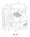
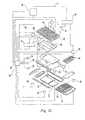
- Embodiments of an exemplary patient support member 23are shown in exploded schematic view in FIGS. 2 , 2 a , 2 b , and 2 c .
- Patient support member 23may include pressurizable bladders or support zones including bladders 40 , 42 , 44 , 46 and 48 .
- Schematically shown in FIGS. 2 , 2 a , 2 b , and 2 cis a pressure control assembly or fluid delivery system 50 that regulates the fluid pressure within bladders 40 , 42 , 44 , 46 and 48 .
- Bladders 40 , 42 and 44are designed to reduce interface pressures between the patient and patient support surface 24 and thereby inhibit the formation of pressure ulcers.
- Bladders 40 , 42 and 44may also be employed for therapeutic purposes as is known in the art. As shown in FIG. 2 c , bladders 46 , 48 may be provided to be used by a caregiver to help turn the patient when moving the patient, changing the bed linens or when otherwise desirable. Bladders 46 , 48 are normally uninflated but one of the two turning bladders 46 , 48 may be inflated when it is desired to turn the patient.
- First bladder 40is located in first section 30 and is positioned proximate head end 26 to provide support for that part of the patient bearing on patient support surface 24 proximate head end 28 .
- First bladder 40will typically provide support for the head and upper torso of the patient.
- Second bladder 42is located in second section 32 and is positioned substantially centrally between head end 26 and foot end 28 of patient support surface 24 to provide support for that part of the patient bearing on patient support surface 24 proximate a midpoint between head end 26 and foot end 28 .
- Second bladder 42will typically provide support for the pelvic region or midsection of the patient.
- Third bladder 44is located in third section 44 and is positioned near foot end 28 of patient support surface 24 to provide support for that part of the patient bearing on patient support surface 24 near foot end 28 .
- Third bladder 44will typically provide support for the lower legs and heels of the patient.
- a compressible or extendable foam support member 52is located in third section 34 and is positioned between second bladder 42 and third bladder 44 .
- the length of third section 34can be adjusted to place third bladder 44 in a position to support the heels of the patient with foam member 52 expanding and contracting to allow for the expansion and contraction of third section 34 .
- Foam member 52is positioned to provide support for portions of the thighs and upper calves of the patient which typically do not generate significant interface pressures on patient support surface 24 .
- a foam topper(not shown) may be placed over bladders 40 , 42 , 44 and extendable foam member 52 to form a generally continuous upper layer for patient support member 23 .
- Other suitable structures for use as patient support member 23are disclosed by Washburn et al.
- bladders 40 , 42 , 44 , 46 , 48are inflatable air bladders, however, alternative embodiments may use pressurizable bladders that are filled with other fluids that are either gaseous or liquid.
- FIG. 2schematically shows a pressure control assembly 50 , which regulates the fluid pressures within bladders 40 , 42 , 44 and includes one or more of a first, second and third pressure sensing devices 54 , 56 , 58 , e.g., pressure transducers, for monitoring the fluid pressure within at least one of first, second and third bladders 40 , 42 , 44 .
- a first, second and third pressure sensing devices 54 , 56 , 58e.g., pressure transducers
- sensors 54 , 56 , 58are installed within the bladders; i.e., device 54 is installed in first bladder 40 for measuring the fluid pressure within first bladder 40 ; device 56 is installed in second bladder 42 for measuring the fluid pressure within second bladder 42 ; and device 58 is installed in third bladder 44 for measuring the fluid pressure within third bladder 44 .
- the readings of pressure sensing devices 54 , 56 , 58are communicated to controller 60 via wiring.
- sensors 54 , 56 , 58are not located within the bladders.
- sensorsare coupled to the one or more bladders and also to the controller 60 between the controller and the bladder via fluid communication lines and electrical wiring 55 , 57 , 59 to provide a distal sensing mechanism as that term is known in the art.
- An example of a type of distal sensing systemcan be found in the VersaCare® and Zonecare® products manufactured by the assignee of the present invention.
- the one or more of sensors 54 , 56 , 58are located in line with valves 66 , 68 , 70 , to provide a proximal sensing mechanism as that term is known in the art.
- a type of proximal sensing systemcan be found in the Totalcare® product manufactured by the assignee of the present invention.
- Locating the sensors within the bladdersmay be desirable, for example to provide greater sensing accuracy and/or to reduce the time delay between sensing and controller responses. Locating the sensors outside the bladders, such as in either the distal or proximal sensing configuration may be desirable to reduce manufacturing costs or for other reasons. Additional pressure sensing devices (not shown) may be positioned to monitor the pressure in turning bladders 46 , 48 as shown in FIG. 2 c.
- bladders 40 , 42 , 44are not in direct fluid communication with each other.
- Each of the bladders 40 , 42 , 44may have a different fluid pressure.
- an air supplysuch as a compressor 62 which is mounted in the power supply box of hospital bed 20 , is employed to selectively supply each of the bladders 40 , 42 , 44 with pressurized air (i.e., air that is at a pressure above that of the ambient air pressure).
- An air blower or other suitable equipmentcould alternatively be used to supply pressurized air to bladders 40 , 42 , 44 .
- Various air handling circuitscan be employed to communicate the pressurized air discharged from compressor 62 to bladders 40 , 42 , 44 whereby the pressure within the bladders can be increased.
- air compressor 62has a discharge line 63 which feeds a manifold chamber 64 .
- the flow of pressurized air from manifold 64 to first bladder 40is regulated by valve 66 .
- Valve 68regulates the flow of pressurized air to bladder 42 from manifold 64 while valve 70 regulates the flow of pressurized air to bladder 44 from manifold 64 .
- the operation of each of the valves 66 , 68 and 70is regulated by controller 60 .
- Bladders 40 , 42 , 44can not only be selectively supplied with pressurized air by compressor 62 via manifold 64 and valves 66 , 68 , 70 , but they may also be selectively and independently vented when it desired to reduce the fluid pressure in one or more of the bladders 40 , 42 , 44 .
- a vent valve 72is in fluid communication with first bladder 40
- vent valve 74is in fluid communication with second bladder 42
- vent valve 76is in fluid communication with third bladder 44 .
- the operation of each of the vent valves 72 , 74 , 76is controlled by controller 60 .
- each of the vent valves 72 , 74 , 76are depicted as venting into box 78 .
- intake line 61 of compressor 62is shown in communication with box 78 .
- box 78represents a vacuum manifold, however, in alternative embodiments, valves 72 , 74 , 76 could vent into the ambient environment and intake line 61 could intake air from the ambient environment whereby box 78 would represent the ambient environment.
- the ability to apply a vacuum at the outlets of bladders 40 , 42may be beneficial when using bladders for therapeutic purposes which require relatively rapid changes in the pressure of the bladders.
- the pressure control assembly or air delivery system 50independently regulates the fluid pressure of the first, second and third bladders 40 , 42 , 44 and each of these bladders may have a different target pressure to which the fluid pressure in the different bladders 40 , 42 , 44 is separately and independently adjusted.
- pressure adjustment of the bladders 40 , 42 , 44may occur simultaneously or at different times or spaced apart time intervals.
- Each of the bladders or support zones 40 , 42 , 44may take the form of a single relatively large bladder or they may take the form of a bladder assembly having a plurality of smaller bladders in mutual fluid communication with the bladder assembly having an intake or “fill” valve and a vent valve.
- a bladder assembly 40could be formed by a series of smaller bladders that are in fluid communication with each other so that each of the smaller bladders forming bladder assembly 40 are each at the same approximate fluid pressure but wherein the smaller bladders forming bladder assembly 40 are not in communication with the bladders forming bladder assemblies 42 , 44 .
- bladder 40could be an assembly of smaller bladders that each have an intake or “fill” valve and vent valve and which are independently regulated by controller 60 .
- the bladders forming bladder assembly 40would each be regulated in accordance with a common set of instructions having a common target pressure while the smaller bladders forming bladder assembly 42 could be regulated in accordance with a different set of common instructions having a different target pressure than that used with bladder assembly 40 .
- bladders or support zones 40 , 42 , 44are each an assemblage of smaller bladders in mutual fluid communication whereby a single valve 66 , 68 , 70 can regulate the inflow of pressurized fluid into the respective bladder assemblages 40 , 42 , 44 and a single valve 72 , 74 , 76 can regulate the discharge of fluid from the respective bladder assemblages 40 , 42 , 44 .
- a dashed line 41indicates the division between bladder 40 and bladder 42 in FIG. 2 .
- valves 66 , 68 , 70 , 72 , 74 , 76are each conventional 12-volt DC solenoid valves.
- Bed 20may also include a plurality of load cells 80 positioned between a weigh frame on which patient support member 23 is mounted and the base frame of bed 20 .
- Load cells 80are in communication with controller 60 and allow the weight of the patient to be monitored. The use of such load cells on a hospital bed for determining the weight of a patient is well known in the art.
- Bed 20may also include a head section angle monitor 31 , such as an angle sensor to monitor changes in the elevation of the first section 30 or first bladder 40 relative to a longitudinal axis of the bed.
- first bladder 40is elevated by articulation of first section 30 relative to the frame 22 .
- a linear actuator 29drives the articulation of first section 30 .
- the linear actuator 29includes a potentiometer 31 which is driven by a motor (not shown). Rotation of a drive wheel of the potentiometer 31 changes the resistance value of the potentiometer 31 and thereby provides an indication of the length of linear actuator 29 .
- the length of linear actuator 29is correlated by the controller 60 to an angle of articulation of first section 30 relative to a longitudinal axis of frame 22 and the resulting angle of articulation of first bladder 40 .
- Other suitable means of determining the angle of articulation of first bladder 40may also be used, such as a ball switch.
- a ball switchmay be coupled to or integrated with either first section 30 or first bladder 40 .
- Programmable controller 60is configured to monitor the pressure values sensed by devices 54 , 56 , 58 and individually regulate the pressure of the fluid within bladders 40 , 42 , 44 by controlling the operation of compressor 62 and valves 66 , 68 , 70 , 72 , 74 , 76 .
- Air system controller 60also receives input from load cells 80 and a head motor potentiometer coupled to first section 30 so that the patient weight and the position of first section 30 can be used in the regulation of the fluid pressure within bladders or support zones 40 , 42 , 44 . Any suitable controller, or plurality of controllers, can be used to regulate the fluid pressures in bladders 40 , 42 , 44 .
- controller 60is an Atmel T89C51CC01 controller which is a 8051 based CMOS controller commercially available from Atmel Corporation having a place of business in San Jose, Calif.
- Bed 20may have a construction that is generally similar to that of a VersaCareTM bed commercially available from Hill-Rom Company, Inc. having a place of business in Batesville, Ind.
- Another bed structure that can be readily adapted for use with the present inventionis disclosed by Weismiller et al. in U.S. Pat. No. 5,715,548 entitled CHAIR BED the disclosure of which is expressly incorporated herein by reference.
- the operation of the pressure control assembly or air delivery system 50 in regulating the fluid pressure within bladders 40 , 42 , 44 , 46 , 48will now be discussed.
- Turning bladders 46 , 48are deflated in each of these modes except for the right turn-assist and left-turn assist modes.
- bladder 46is inflated while bladder 48 is deflated
- bladder 48is inflated while bladder 46 is deflated.
- the selected bladderis inflated to an extent that the patient is rotated to reach an approximately 20 degree angle with the major plane defined by patient support surface 24 .
- the inflated turn bladderstabilizes for 10 seconds and, after sounding an alarm, deflates quickly.
- This inflation of the turn bladdersmay be used to assist the caregiver in turning the patient, for example, during linen changes, dressing changes, bed panning, back care and other nursing procedures.
- the max-inflate modepressurizes each of the first, second and third bladders 40 , 42 , 43 to their maximum operating pressure to provide a firm patient support surface.
- the max-inflate modeis used for only short periods of time, e.g., when the patient is entering or exiting the bed or eating a meal.
- the pressure in bladders 40 , 42is maintained within a pressure range of 25 to 29 (inches water).
- the fluid pressure within bladders 40 , 42is maintained in a pressure range of 20 to 30 (inches water).
- the pressure relief modeseeks to reduce the interface pressure between patient support surface 24 and the patient by maintaining the pressure of each of the bladders 40 , 42 , 44 at a target pressure or within a window or range of acceptable pressures or within an acceptable tolerance of a target pressure.
- a separate target pressure or range of acceptable pressuresis defined for each of the bladders or zones 40 , 42 , 44 .
- These target pressures or ranges of acceptable pressuresare determined as a function of the weight of the patient.
- the acceptable range of pressuresis also a function of the position of section 30 with respect to a longitudinal axis of the bed 20 , or “head angle” position.
- FIGS. 5-7contains a chart setting forth the sensed pressure within one of the bladders 40 , 42 , 44 over time.
- FIGS. 5-7illustrate three different representative scenarios for the adjustment of the pressure which initiate the adjustment action after the elapse of different length time periods following the detection of a pressure value.
- FIGS. 5-7are concerned with the pressure in only one of the bladders 40 , 42 , 44 which are separately and independently monitored and adjusted. Thus, the pressure of the other two bladders would be monitored and adjusted, based upon separate pressure readings, in accordance with the monitoring and adjustment represented by the charts depicted in FIGS. 5-7 .
- the pressure in the bladders 40 , 42 , 44is separately and independently adjusted, the pressure adjustment of any or all of these bladders may occur at the same time or at spaced apart times. For example, if two (2) or more of the bladders are out of range and need to be deflated, then deflation of both bladders may occur at the same time or substantially simultaneously. However, if more than one (1) bladder needs to be inflated, it may be necessary to inflate the bladders sequentially instead of simultaneously. If the bladders are inflated sequentially, the bladders may each be assigned a priority, which is then used to determine the order of inflation.
- a higher prioritymay be assigned to the bladder having the greatest difference between sensed value and calculated value in the shortest amount of time (i.e., the greatest change in pressure in the least amount of time).
- articulation of a deck section of the bed 20may affect the priority. For instance, if the head section is articulated above thirty (30) degrees, then the seat section bladder may be given higher priority than the head section bladder and thus, inflated first.
- Other factors, including where the bladders are locatedi.e., foot, head, or seat section) may also be used to determine priority for adjusting the bladders.
- the pressure Tis the target pressure at which it is desired to maintain the bladder.
- Pressures A L and A Urepresent the lower and upper limit respectively of the range of acceptable pressure, i.e., Window A.
- target pressure Tis at the midpoint of Window A, however, alternative embodiments could employ upper and lower limits to the acceptable range defining Window A that are not equidistant from the target pressure value.
- a patient located on bed 20will occasionally reposition themselves on patient support surface 24 .
- the patientwill likely cause fluid pressure fluctuations in one or more of the bladders 40 , 42 , 44 .
- These pressure fluctuations caused by the repositioning exertions of the patientmay cause the fluid pressure in one or more of bladders 40 , 42 , 44 to reach a value outside the acceptable range of pressure values defined by Window A.
- the pressure reading within bladders 40 , 42 , 44will once again stabilize.
- the newly stabilized fluid pressuremay or may not be within the acceptable range of pressure values defined by Window A.
- the fluid pressure within one of the bladdersis actively adjusted during the course of the patient's repositioning exertions, it may prove necessary to “undo” the adjustment once the patient reached their new position on patient support surface 24 and the fluid pressure within the bladders has restabilized. Moreover, during repositioning, the patient may react to the inflation and/or deflation of bladders 40 , 42 , 44 and thereby prolong the cycle of pressure fluctuations and responsive adjustments. By delaying the adjustment of the fluid pressure after the initial detection of a pressure value outside the acceptable range of Window A some of these unnecessary fluid pressure adjustments can be avoided.
- a delay in returning the fluid pressure to a more acceptable valuecan be undesirable. For example, if the pressure diverges significantly above the acceptable range, the bladder could be damaged while, if the pressure diverges significantly below the acceptable range, the patient could “bottom out” and bear directly against the structure underlying the bladder.
- a second window or range of pressure valuesis defined immediately outside the range of acceptable pressure values both above and below the range of acceptable pressure values. This second set of ranges, i.e., Window B, is between pressure values A L and B L below Window A and is between pressure values A U and B U above Window A.
- a U and A Lare chosen so that when the pressure within the bladder is in Window A, the anticipated interface pressure between the patient and patient support surfaces will provide pressure relief to the patient on bed 20 .
- the values of B U and B Lare chosen such that when the pressure within the bladder falls outside of Window A and enters Window B, the anticipated interface pressure between the bladder and patient will be acceptable for a brief time period without requiring immediate adjustment of the pressure.
- the pressures defining Window B in the illustrated embodimentare chosen so that the anticipated interface pressures resulting from a Window B condition would be acceptable for a time period ranging from approximately 30 minutes to approximately 2 hours.
- the active adjustment of the pressureis only initiated if the pressure does not return to Window A within a variable time period.
- the illustrated embodimentalso imposes a maximum value of about 5 minutes upon this time period and if, after detecting a pressure value in Window B, the pressure has not yet returned to Window A and no pressure adjustment has been initiated after the elapse this maximum time period value, pressure control assembly 50 will initiate an adjustment of the pressure.
- the delay in the adjustment time periodis different for each Window B 1 . . . B N .
- the delay periodis different depending upon which Window B 1 . . . B N the measured pressure is in.
- Pressure values above B U and below B Ldefine an additional range of pressure values, i.e., Window C.
- Window CWhen the bladder pressure falls within Window C it will generally not provide any effective pressure relief to the patient.
- the bladder pressure enters Window Cit is adjusted within a time period that is less than the time delay associated with the lesser pressure divergences of Window B. For example, the time period between detecting a pressure value in Window C and initiating the adjustment of the pressure in that bladder could fall within a range from about 0 to about 60 seconds. In the illustrated embodiment, once a pressure in Window C an adjustment of the pressure within that bladder is initiated within about 30 seconds.
- FIG. 5illustrates the situation where the fluid pressure diverges downwardly from the target pressure into Window B, between times T 1 and T 2 , but does not extend into Window C.
- the pressure control assembly 50does not immediately initiate an adjustment of the pressure and it is only when the pressure has not returned to the acceptable pressure range by time period T 4 that an adjustment of the pressure is initiated.
- FIG. 6illustrates a situation where the pressure diverges more significantly upwardly from Window A and passes through Window B to reach a pressure in Window C. Once this value in Window C above pressure B U has been detected the adjustment of the pressure within the bladder is initiated without a time delay.
- FIG. 6depicts the correction of the pressure overshooting to a value slightly below Window A before it is corrected to the desired pressure within Window A.
- the measured pressureis not within Window A after the initial adjustment or corrective action (e.g., a controlled introduction of pressurized air into the bladder or a controlled partial venting of the bladder), a second adjustment will be allowed.
- a short delay periode.g., about 20 seconds, will then be required regardless of the pressure value and following adjustments will take place based upon the then current pressure value.
- the target pressure to which the adjustment seeks to return the pressureis not the actual central target pressure T as depicted in FIG. 6 .
- T Lwhich is slightly less than T
- T Uwhich is slightly greater than T.
- the pressureis returned to one of these two values as best depicted in FIG. 5 .
- T Lwhich is slightly less than T
- T Uwhich is slightly greater than T.
- FIGS. 6 and 7have been simplified and do not illustrate lines at pressure values T U and T L separately from the line at pressure value T. Similarly, for purposes of graphical clarity, Windows A, B and C are only labeled in FIG. 5 .
- a systemwherein the time delay associated with the initiation of the pressure adjustment varies between two different and fixed values with greater divergences from the acceptable pressure range, resulting in shorter time delays.
- a system having a variable time delayis provided by using a fixed time delay, e.g., five or ten minutes, when the pressure diverges into Window B and a shorter fixed time delay, e.g., 30 seconds or a minute, when the pressure diverges into Window C.
- a more sophisticated systemcan be used to provide even greater flexibility.
- the illustrated embodimentutilizes a short fixed time delay for when the detected pressure enters Window C, but utilizes a time delay that is a function of the stability of the pressure reading when the pressure is in Window B.
- a positive adjustment of the pressure to return the pressure to Window Aonly occurs if the pressure maintains a relatively stable value in Window B for a predefined time period or the maximum time period elapses without the pressure returning to Window A.
- FIG. 5illustrates a situation where the pressure diverges into Window B and remains stable within Window B from approximately time period T 2 to time period T 4 at which time the adjustment of the pressure is initiated.
- the pressurediverges into Window B and fluctuates within Window B from time period T 2 until after time period T 4 .
- the pressurethen stabilizes within Window B and remains relatively stable from approximately time period T 5 until time period T 7 when the pressure is positively adjusted and returned to Window A.
- the initial fluctuation of pressure in Window B in the situation depicted in FIG. 7delayed the adjustment of the pressure which only occurred after the pressure had stabilized within Window B. If the pressure had remained in Window B and remained erratic, an adjustment would have occurred after the elapse of the maximum time delay period, which in the illustrated embodiment is about 10 minutes.
- the pressure traces shown in FIGS. 5-7are idealized traces selected to illustrate the operation of the system and a “stable” pressure reading will typically not have the perfectly consistent character shown in the Figures. The stability of the pressure can be determined in various manners.
- the current pressure valuecan be compared to a moving average of the most recent pressure readings and when the current pressure values remain within a predefined range surrounding the moving average for a predefined time period, the pressure can be considered to have stabilized.
- the process used in the illustrated embodiment to assess the stability of the pressureis described in greater detail below.
- the “boundary” values of T, T U , T L , A U , A L , B U and B Lall remain constant over time.
- these boundary valuesmay be determined as a function of other variables that may include the patient weight, the angular position of section 30 , and the location of a patient on the mattress.
- the boundary valuesmay change, for example, if sensors detect a patient changing from a supine or prone position to a sitting up position, or moving from the center of the bed to the edge of the bed, or vice-versa.
- the boundary valuescan change over time.
- the patient weight readingscan also be employed to impose a delay on the adjustment of the fluid pressure within bladders 40 , 42 , 44 .
- a change of at least 5 pounds in the detected weight of the patientwill often be indicative of patient movement on the bed. Accordingly, whenever a change in the patient weight of at least 5 pounds is detected, all adjustments of bladder pressure can be delayed for a predefined time period, e.g., 30 or 60 seconds, to limit unnecessary pressure adjustments.
- the sleep modeis designed to minimize the disturbance of the patient.
- the air compressor noise and the raising and lowering of patient support surface 24 associated with the adjustment of the bladder pressureshas the potential to disturb the sleep of some patients.
- a sleep mode having a length of eight hoursis provided.
- the sleep modeoperates in a manner similar to the pressure relief mode but the maximum time period for initiating adjustment when the pressure is in Window B is increased from about 5 minutes to about 10 minutes and the maximum time period for initiating adjustment when the pressure is in Window C is increased from about 30 seconds to about 1 minute. It is also possible to increase the range of acceptable pressures defining Window A when entering the sleep mode to further minimize the number of times that the pressure within bladders 40 , 42 , 44 must be adjusted.
- the illustrated embodimentremains in the sleep mode after adjusting the pressure in the bladders and only returns to the normal pressure relief mode after an eight hour time period has elapsed, or, the sleep mode has been overridden by some other operation of the controller, e.g., placing the system in CPR (Max-inflate) mode or manually returning the controller to normal pressure relief mode.
- CPRMax-inflate
- the off modedeactivates the system and is used when cleaning or conducting maintenance on bed 20 or when bed 20 is not in use.
- the off modeis not employed when a patient is using bed 20 .
- the systemWhen the system is turned back on after being placed in the off mode, the system starts out in the pressure relief mode.
- the seat bladderi.e., bladder 42 will be subjected to a “seat boost” procedure.
- the pressure in bladder 42is increased to a relatively high pressure and then returned to the target pressure within Window A.
- This procedureis employed because bladder 42 can have two different volumes for a particular pressure value and the seat boosting operation ensures that bladder is at the desired volume for the target pressure.
- Such seat boosting proceduresare known in the art and are typically employed when the head section of the bed, e.g., section 30 , is being raised and has been raised by a sufficient amount to change the boundary value pressure values of the seat bladder.
- the illustrated embodimentemploys the seat boosting procedure whenever the angle of section 30 is altered by about 3 degrees or more regardless of whether it is being raised or lowered and regardless of whether the target pressure of any of the bladders 40 , 42 , 44 have been altered by the change in position of section 30 .
- a similar “seat boost” proceduremay alternatively or additionally be triggered by a change in a patient's location or position on the mattress. For example, if sensors detect the patient moving from a supine or prone position to a sitting up position, or from the center of the bed to an edge of the bed, or vice versa, pressure in bladder 42 may be adjusted according to the procedure described above.
- FIGS. 4 , 4 a , 4 b , 5 , 5 a , 5 b , 6An exemplary set of equations that are used with the illustrated embodiment and a description of the instructional logic underlying the operation of pressure control assembly 50 will now be presented with the aid of the flow charts illustrated in FIGS. 4 , 4 a , 4 b , 5 , 5 a , 5 b , 6 .
- the position of section 30is employed by some of the formulas defining the boundary values and the following regions have been defined for the position of section 30 or “Head_Elevation” for this purpose:
- Head_ElevationValue for use in Region Min. Angle Max. Angle Equations 0 0 degrees 7.5 degrees 7.5 degrees 1 3.5 degrees 15 degrees 15 degrees 2 11 degrees 30 degrees 30 degrees 3 26 degrees 45 degrees 45 degrees 4 41 degrees 65 degrees 60 degrees
- Pressure_Head(Patient_Weight/49.70)+((Head_Elevation/ ⁇ 77.4)+3.4) wherein: “Patient_Weight” is the weight of the patient in tenths of pounds with no decimal point; and “Head_Elevation” is in degrees.
- the obtained value of “Pressure_Head”is the target pressure value T for first bladder 40 measured in inches of water.
- the boundary values defining Window A for first bladder 40are then determined in accordance with the following table:
- B UHigh Pressure Low Pressure Boundary Value
- B LBoundary Value
- Pressure_Head + 1 B Lis set at the same value (inches water) as A L (inches water)
- the obtained value of “Pressure_Seat”is the target pressure value T for second bladder 42 measured in inches of water.
- the boundary values defining Window A for second bladder 42are then determined in accordance with the following table:
- Boundary ValueA U
- a LValue (T U ) Value (T L ) Pressure_Seat + 1 Pressure_Seat ⁇ 1 Pressure_ Seat + 0.5 Pressure_Seat ⁇ 0.5 (inches water) (inches water) (inches water) (inches water)
- Pressure_Seatis then used to determine the parameters of Window B in accordance with the following table:
- the flow chart depicted in FIG. 3is shown in greater detail in FIGS. 3 a and 3 b and illustrates the AutoDelay function of pressure control assembly 50 for one of bladders 40 , 42 , 44 .
- the AutoDelay functionhas four different states as represented by boxes 90 , 96 , 108 and 116 .
- State 1box 90 , generally corresponds to the pressure being within Window A;
- State 2generally corresponds to the pressure being within Window B;
- State 3generally corresponds to the pressure being within Window C and
- State 4corresponds to the initiation of an active adjustment of the pressure in the bladder.
- the “MS” or Major Sample pressure values utilized by algorithm depicted in FIG. 3are obtained by averaging the five most recent pressure values obtained from the relevant pressure sensing device which are each representative of the pressure readings over a 100 millisecond time period.
- the MS valueis representative of the pressure within the bladder during the previous 500 milliseconds.
- the TimeoutAis reset to 0 (if the system departs from Window A and State 1 , the TimeoutA value will represent the time elapsed since the pressure departed from Window A).
- the MS valueis checked to determine if it falls within Window C, if it is within Window C, the system proceeds to box 106 where the timer for Window C, i.e., TimerInC, is initiated. If, at box 92 , the MS value is not in Window C, the system proceeds to box 94 where it is determined whether the MS value is in Window B. If the MS value is not in Window B, the pressure must be in Window A and the system returns to box 90 .
- the systemproceeds to box 96 and enters State 2 .
- the current MS valueis checked to see if it has returned to Window A, if so, the system returns to box 90 without initiating an adjustment of the pressure. If the current MS value is outside Window A, the system proceeds to box 100 where the TimerOutA is checked to determine if the pressure has been outside Window A for more than 5 minutes. (In the sleep mode, this value is increased to 10 minutes.) If so, the system proceeds to box 116 where a flag for initiating the adjustment of the pressure is set. If the pressure has been outside Window A for less than 5 minutes, the system proceeds to box 102 where the stability of the pressure values is checked. ( FIG.
- box 108After initiating the Window C timer, box 108 indicates that the system is in State 3 and the system then proceeds to box 110 .
- the current MS valueis checked to see if it is in Window A, if so, the system returns to box 90 and State 1 without active adjustment of the pressure. If not, the system proceeds to box 112 where it is determined whether the current MS value is in Window B. If so, the system returns to box 96 and State 2 . If not, the system proceeds to box 114 where it is determined whether the system has been in State 3 , Window C, for more than 15 seconds. If the system has been in State 3 for less than 15 seconds, the system returns to box 110 via box 108 .
- the systemproceeds to box 116 and enters State 4 where a pressure adjustment is initiated by setting the AdjustReady Flag. After setting the AdjustReady Flag, the system proceeds to box 118 . It is determined whether the pressure adjustment procedure has been completed and the AdjustReady Flag been cleared. If the AdjustReady Flag has been cleared, the system returns to box 90 and State 1 . If the AdjustReady Flag has not been cleared, the system remains in State 4 and returns to box 116 .
- the AdjustReady Flagwhen actively adjusting the pressure of a bladder, if, 2 seconds after making the first adjustment, the pressure is within Window A, the AdjustReady Flag is cleared and the system returns to box 90 . If, 2 seconds after making the first adjustment, the pressure is not within Window A, a second adjustment is made. After making such a second adjustment, the AdjustReady Flag is cleared and the process returns to box 90 . Twenty seconds must elapse following such a second adjustment before an addition adjustment of the bladder pressure is allowed.
- box 102represents the determination of whether or not the pressure has been stable for the preceding 30 seconds.
- FIG. 4presents a flowchart representing the process by which this determination is made.
- Box 120represents the acquisition of an array of most recent pressure values (including at least the most recent five Major Sample values) for a single one of the bladders 40 , 42 , 44 .
- the systemthen proceeds to box 122 where the Count is incremented by 1.
- box 124it is determined whether the Count has reached 5. If not, the system returns to box 120 until the Count reaches 5 and the system can proceed to box 126 .
- the average of the most recent 5 Major Samplesi.e., a moving average, is calculated.
- the most recent Major Sampleis compared to average value of the most recent Major Samples. If the difference determined at box 128 is greater than 0.5 inches water, the pressure is considered not stable and the Stability Count is returned to 0. If the difference determined at box 128 is less than 0.5 inches water, the pressure is considered stable and the Stability Count is increased by 1. The value of the Stability Count is thereby representative of the time for which the pressure has remained stable with larger Stability Count values pertaining to longer periods of stable pressure values.
- the current Major Sample valueis set as the average value and the process returns to box 120 .
Landscapes
- Health & Medical Sciences (AREA)
- Nursing (AREA)
- Life Sciences & Earth Sciences (AREA)
- Animal Behavior & Ethology (AREA)
- General Health & Medical Sciences (AREA)
- Public Health (AREA)
- Veterinary Medicine (AREA)
- Invalid Beds And Related Equipment (AREA)
- Accommodation For Nursing Or Treatment Tables (AREA)
Abstract
Description
| “Head_Elevation” | |||||
| Value for use in | |||||
| Region | Min. Angle | Max. | Equations | ||
| 0 | 0 | degrees | 7.5 degrees | 7.5 | ||
| 1 | 3.5 | 15 | 15 | |||
| 2 | 11 | 30 | 30 | |||
| 3 | 26 | degrees | 45 degrees | 45 | ||
| 4 | 41 | degrees | 65 | 60 degrees | ||
Pressure_Head=(Patient_Weight/49.70)+((Head_Elevation/−77.4)+3.4)
wherein:
“Patient_Weight” is the weight of the patient in tenths of pounds with no decimal point; and “Head_Elevation” is in degrees. The obtained value of “Pressure_Head” is the target pressure value T for
| High Pressure | Low Pressure | Inflate Boundary | Deflate Boundary |
| Boundary Value (AU) | Boundary Value (AL) | Value (TU) | Value (TL) |
| Pressure_Head − 1 | Pressure_ Head + 0.5 | Pressure_Head − 0.5 | |
| (inches water) | (inches water) | (inches water) | (inches water) |
Pressure_Head=((Patient_Weight/100)+1)*3
wherein:
“Patient_Weight” is the weight of the patient in tenths of pounds with no decimal point. The obtained value of “Pressure_Head” is then used to determine the parameters of Window B in accordance with the following table:
| High Pressure | Low Pressure | ||
| Boundary Value (BU) | Boundary Value (BL) | ||
| Pressure_Head + 1 | BLis set at the same value | ||
| (inches water) | as AL(inches water) | ||
Pressure_Seat=(Patient_Weight/31.10)+((Head_Elevation/12.2)+1.8)
and when the Head_Elevation is greater than 55 degrees:
Pressure_Seat=((Patient_Weight/50)+4)*((Head_Elevation/12.2)+1)
wherein:
“Patient_Weight” is the weight of the patient in tenths of pounds with no decimal point; and
“Head_Elevation” is in degrees. The obtained value of “Pressure_Seat” is the target pressure value T for
| High Pressure | Low Pressure | Inflate Boundary | Deflate Boundary |
| Boundary Value (AU) | Boundary Value (AL) | Value (TU) | Value (TL) |
| Pressure_Seat − 1 | Pressure_ Seat + 0.5 | Pressure_Seat − 0.5 | |
| (inches water) | (inches water) | (inches water) | (inches water) |
Pressure_Seat=((Patient_Weight/50)+4)*((Head_Elevation/60)+1)
wherein:
“Patient_Weight” is the weight of the patient in tenths of pounds with no decimal point; and
“Head_Elevation” is in degrees. The obtained value of “Pressure_Seat” is then used to determine the parameters of Window B in accordance with the following table:
| High Pressure | Low Pressure | ||
| Boundary Value (BU) | Boundary Value (BL) | ||
| Pressure_Seat + 1 | BLis set at the same value | ||
| (inches water) | as AL(inches water) | ||
Pressure_Heel=((Patient_Weight/200)+1)
wherein:
“Patient_Weight” is the weight of the patient in tenths of pounds with no decimal point. The obtained value of “Pressure_Heel” is the target pressure value T for
| High Pressure | Low Pressure | Inflate Boundary | Deflate Boundary |
| Boundary Value (AU) | Boundary Value (AL) | Value (TU) | Value (TL) |
| Pressure_Heel + 0.50 | Pressure_Heel − 0.50 | Pressure_ Heel + 0.25 | Pressure_Heel − 0.25 |
| (inches water) | (inches water) | (inches water) | (inches water) |
Pressure_Heel=((Patient_Weight/200)+1)
wherein:
“Patient_Weight” is the weight of the patient in tenths of pounds with no decimal point. The obtained value of “Pressure_Heel” is then used to determine the parameters of Window B in accordance with the following table:
| High Pressure | Low Pressure |
| Boundary Value (BU) | Boundary Value (BL) |
| Pressure_Heel + 1.5 | Pressure_Heel − 1.5 or 0.0, whichever is |
| (inches water) | greater (inches water) |
Claims (34)
Priority Applications (1)
| Application Number | Priority Date | Filing Date | Title |
|---|---|---|---|
| US11/916,766US8090478B2 (en) | 2005-06-10 | 2006-06-12 | Control for pressurized bladder in a patient support apparatus |
Applications Claiming Priority (4)
| Application Number | Priority Date | Filing Date | Title |
|---|---|---|---|
| US68934005P | 2005-06-10 | 2005-06-10 | |
| US70264505P | 2005-07-26 | 2005-07-26 | |
| PCT/US2006/022732WO2006135845A2 (en) | 2005-06-10 | 2006-06-12 | Control for pressurized bladder in a patient support apparatus |
| US11/916,766US8090478B2 (en) | 2005-06-10 | 2006-06-12 | Control for pressurized bladder in a patient support apparatus |
Related Parent Applications (1)
| Application Number | Title | Priority Date | Filing Date |
|---|---|---|---|
| PCT/US2006/022732A-371-Of-InternationalWO2006135845A2 (en) | 2005-06-10 | 2006-06-12 | Control for pressurized bladder in a patient support apparatus |
Related Child Applications (1)
| Application Number | Title | Priority Date | Filing Date |
|---|---|---|---|
| US13/335,373ContinuationUS8620477B2 (en) | 2005-06-10 | 2011-12-22 | Control for pressurized bladder in a patient support apparatus |
Publications (2)
| Publication Number | Publication Date |
|---|---|
| US20100063638A1 US20100063638A1 (en) | 2010-03-11 |
| US8090478B2true US8090478B2 (en) | 2012-01-03 |
Family
ID=37532864
Family Applications (3)
| Application Number | Title | Priority Date | Filing Date |
|---|---|---|---|
| US11/916,766Active2028-04-21US8090478B2 (en) | 2005-06-10 | 2006-06-12 | Control for pressurized bladder in a patient support apparatus |
| US13/335,373ActiveUS8620477B2 (en) | 2005-06-10 | 2011-12-22 | Control for pressurized bladder in a patient support apparatus |
| US14/132,761ActiveUS9107511B2 (en) | 2005-06-10 | 2013-12-18 | Control for pressurized bladder in a patient support apparatus |
Family Applications After (2)
| Application Number | Title | Priority Date | Filing Date |
|---|---|---|---|
| US13/335,373ActiveUS8620477B2 (en) | 2005-06-10 | 2011-12-22 | Control for pressurized bladder in a patient support apparatus |
| US14/132,761ActiveUS9107511B2 (en) | 2005-06-10 | 2013-12-18 | Control for pressurized bladder in a patient support apparatus |
Country Status (5)
| Country | Link |
|---|---|
| US (3) | US8090478B2 (en) |
| EP (1) | EP1893822A4 (en) |
| JP (1) | JP5208732B2 (en) |
| AU (1) | AU2006257880B2 (en) |
| WO (1) | WO2006135845A2 (en) |
Cited By (43)
| Publication number | Priority date | Publication date | Assignee | Title |
|---|---|---|---|---|
| US20110083271A1 (en)* | 2009-10-09 | 2011-04-14 | Bhai Aziz A | Head of bed angle mounting, calibration, and monitoring system |
| US8839473B1 (en) | 2012-11-13 | 2014-09-23 | Alex Catala | Air mattress comfort adjustment system |
| US8893339B2 (en) | 2013-03-14 | 2014-11-25 | Select Comfort Corporation | System and method for adjusting settings of a bed with a remote control |
| US8973186B2 (en) | 2011-12-08 | 2015-03-10 | Hill-Rom Services, Inc. | Optimization of the operation of a patient-support apparatus based on patient response |
| US9107511B2 (en) | 2005-06-10 | 2015-08-18 | Hill-Rom Services, Inc. | Control for pressurized bladder in a patient support apparatus |
| US9370457B2 (en) | 2013-03-14 | 2016-06-21 | Select Comfort Corporation | Inflatable air mattress snoring detection and response |
| US9392879B2 (en) | 2013-03-14 | 2016-07-19 | Select Comfort Corporation | Inflatable air mattress system architecture |
| US9445751B2 (en) | 2013-07-18 | 2016-09-20 | Sleepiq Labs, Inc. | Device and method of monitoring a position and predicting an exit of a subject on or from a substrate |
| US9468307B2 (en) | 2012-09-05 | 2016-10-18 | Stryker Corporation | Inflatable mattress and control methods |
| US9504416B2 (en) | 2013-07-03 | 2016-11-29 | Sleepiq Labs Inc. | Smart seat monitoring system |
| US9510688B2 (en) | 2013-03-14 | 2016-12-06 | Select Comfort Corporation | Inflatable air mattress system with detection techniques |
| US9635953B2 (en) | 2013-03-14 | 2017-05-02 | Sleepiq Labs Inc. | Inflatable air mattress autofill and off bed pressure adjustment |
| US9655795B2 (en)* | 2012-04-10 | 2017-05-23 | Hill-Rom Services, Inc. | Occupant support with a migration sensitive bladder and method for migration detection |
| US9770114B2 (en) | 2013-12-30 | 2017-09-26 | Select Comfort Corporation | Inflatable air mattress with integrated control |
| US9844275B2 (en) | 2013-03-14 | 2017-12-19 | Select Comfort Corporation | Inflatable air mattress with light and voice controls |
| US9875633B2 (en) | 2014-09-11 | 2018-01-23 | Hill-Rom Sas | Patient support apparatus |
| US10058467B2 (en) | 2013-03-14 | 2018-08-28 | Sleep Number Corporation | Partner snore feature for adjustable bed foundation |
| US10092242B2 (en) | 2015-01-05 | 2018-10-09 | Sleep Number Corporation | Bed with user occupancy tracking |
| US10149549B2 (en) | 2015-08-06 | 2018-12-11 | Sleep Number Corporation | Diagnostics of bed and bedroom environment |
| US10182661B2 (en) | 2013-03-14 | 2019-01-22 | Sleep Number Corporation and Select Comfort Retail Corporation | Inflatable air mattress alert and monitoring system |
| US10448749B2 (en) | 2014-10-10 | 2019-10-22 | Sleep Number Corporation | Bed having logic controller |
| US10504353B2 (en) | 2015-07-27 | 2019-12-10 | Hill-Rom Services, Inc. | Customized bed exit warnings to modify patient behavior |
| USD877915S1 (en) | 2018-09-28 | 2020-03-10 | Stryker Corporation | Crib assembly |
| USD879966S1 (en) | 2018-09-28 | 2020-03-31 | Stryker Corporation | Crib assembly |
| US10674832B2 (en) | 2013-12-30 | 2020-06-09 | Sleep Number Corporation | Inflatable air mattress with integrated control |
| USD888963S1 (en) | 2018-09-28 | 2020-06-30 | Stryker Corporation | Cover assembly for a patient support |
| USD888962S1 (en) | 2018-09-28 | 2020-06-30 | Stryker Corporation | Cover assembly for a patient support |
| USD888964S1 (en) | 2018-09-28 | 2020-06-30 | Stryker Corporation | Crib assembly for a patient support |
| USD890914S1 (en) | 2018-10-31 | 2020-07-21 | Stryker Corporation | Pump |
| USD892159S1 (en) | 2018-10-31 | 2020-08-04 | Stryker Corporation | Display screen with animated graphical user interface |
| US10736432B2 (en) | 2014-07-18 | 2020-08-11 | Sleep Number Corporation | Automatic sensing and adjustment of a bed system |
| USD893543S1 (en) | 2018-10-31 | 2020-08-18 | Stryker Corporation | Display screen with graphical user interface |
| USD894223S1 (en) | 2018-10-31 | 2020-08-25 | Stryker Corporation | Display screen with animated graphical user interface |
| USD894226S1 (en) | 2018-10-31 | 2020-08-25 | Stryker Corporation | Display screen or portion thereof with graphical user interface |
| USD894957S1 (en) | 2018-10-31 | 2020-09-01 | Stryker Corporation | Display screen or portion thereof with graphical user interface |
| USD894956S1 (en) | 2018-10-31 | 2020-09-01 | Stryker Corporation | Display screen or portion thereof with graphical user interface |
| USD901940S1 (en) | 2018-09-28 | 2020-11-17 | Stryker Corporation | Patient support |
| US11173085B2 (en) | 2017-12-28 | 2021-11-16 | Stryker Corporation | Mattress cover for a mattress providing rotation therapy to a patient |
| US11246775B2 (en) | 2017-12-28 | 2022-02-15 | Stryker Corporation | Patient turning device for a patient support apparatus |
| US11439345B2 (en) | 2006-09-22 | 2022-09-13 | Sleep Number Corporation | Method and apparatus for monitoring vital signs remotely |
| USD977109S1 (en) | 2018-09-28 | 2023-01-31 | Stryker Corporation | Crib assembly for a patient support |
| US11737938B2 (en) | 2017-12-28 | 2023-08-29 | Sleep Number Corporation | Snore sensing bed |
| US12390379B2 (en) | 2017-12-28 | 2025-08-19 | Sleep Number Corporation | Bed having snore detection feature |
Families Citing this family (22)
| Publication number | Priority date | Publication date | Assignee | Title |
|---|---|---|---|---|
| US20110301432A1 (en) | 2010-06-07 | 2011-12-08 | Riley Carl W | Apparatus for supporting and monitoring a person |
| US8525680B2 (en) | 2009-09-18 | 2013-09-03 | Hill-Rom Services, Inc. | Apparatuses for supporting and monitoring a condition of a person |
| US8531307B2 (en)* | 2009-09-18 | 2013-09-10 | Hill-Rom Services, Inc. | Patient support surface index control |
| US9420895B2 (en)* | 2009-12-17 | 2016-08-23 | Stryker Corporation | Patient support |
| CN103974681B (en) | 2010-09-01 | 2017-12-26 | 亨特莱技术有限公司 | Patient support and method |
| EP2666406A3 (en) | 2012-05-22 | 2013-12-04 | Hill-Rom Services, Inc. | Occupant egress prediction systems, methods and devices |
| EP2667313B1 (en) | 2012-05-22 | 2021-08-04 | Hill-Rom Services, Inc. | Adverse condition detection, assessment, and response system |
| US9333136B2 (en) | 2013-02-28 | 2016-05-10 | Hill-Rom Services, Inc. | Sensors in a mattress cover |
| US9801767B2 (en)* | 2013-03-14 | 2017-10-31 | Kap Medical, Inc. | Patient support apparatus and method |
| DE102013104538B4 (en) | 2013-05-03 | 2015-05-21 | MAQUET GmbH | Operating table and method for controlling an operating table |
| US9504620B2 (en)* | 2014-07-23 | 2016-11-29 | American Sterilizer Company | Method of controlling a pressurized mattress system for a support structure |
| US20160242561A1 (en)* | 2015-02-25 | 2016-08-25 | Rapid Air Llc | Airbed control system for simultaneous articulation and pressure adjustment |
| US11058227B2 (en) | 2015-04-23 | 2021-07-13 | Sealy Technology, Llc | Systems and methods for adjusting the firmness and profile of a mattress assembly |
| US10413464B2 (en)* | 2015-05-05 | 2019-09-17 | Hill-Rom Services, Inc. | Multi-mode sacral unloading pressure relief in a patient support surface |
| EP3482734B1 (en)* | 2015-06-15 | 2020-12-09 | Allen Medical Systems, Inc. | Spine table positioner pad with pressure sensing and cooling features |
| EP3205268B1 (en) | 2016-02-11 | 2023-10-25 | Hill-Rom Services, Inc. | Hospital bed |
| US11071668B1 (en)* | 2018-06-04 | 2021-07-27 | Encompass Group, Llc. | Hospital bed with inflatable bladders with random inflation and related methods |
| CN111200573B (en)* | 2018-11-16 | 2022-02-22 | 迈普通信技术股份有限公司 | RPC request calling method and device |
| US11660242B2 (en) | 2019-06-17 | 2023-05-30 | Morgan Leigh Miller | Portable patient turning device |
| US12064383B2 (en) | 2019-08-08 | 2024-08-20 | Sizewise Rentals, L.L.C. | Method for reducing tissue interface pressure |
| US20210227991A1 (en)* | 2020-01-24 | 2021-07-29 | Patientech Llc | Controllable beds |
| US20230000261A1 (en)* | 2021-06-30 | 2023-01-05 | Karen D. Webster | Pressurized Vertical Cylinder Air Chamber Mattress |
Citations (138)
| Publication number | Priority date | Publication date | Assignee | Title |
|---|---|---|---|---|
| US2719986A (en) | 1950-12-16 | 1955-10-11 | Air Mass Inc | Hollow mattress and inflation control therefor |
| US3462778A (en) | 1966-02-25 | 1969-08-26 | Gaymar Ind Inc | Inflatable mattress and pressure system |
| US3879776A (en) | 1974-01-10 | 1975-04-29 | Morris Solen | Variable tension fluid mattress |
| US4224706A (en) | 1978-10-16 | 1980-09-30 | Dial-A-Firm, Inc. | Pneumatic bed |
| US4394784A (en) | 1981-07-08 | 1983-07-26 | Dial-A-Firm International, Inc. | Air bed with firmness control |
| US4542547A (en) | 1982-12-15 | 1985-09-24 | Hiroshi Muroi | Pnuematic mat with sensing means |
| US4634179A (en) | 1982-07-31 | 1987-01-06 | Aisin Seiki Kabushiki Kaisha | Air lumbar support device |
| US4694409A (en) | 1984-06-25 | 1987-09-15 | Monorail, Inc. | Microprocessor based air inflation control system |
| US4694520A (en) | 1986-01-15 | 1987-09-22 | Ssi Medical Services, Inc. | Patient support apparatus |
| US4700180A (en) | 1983-05-04 | 1987-10-13 | Vance Dwight A | Apparatus to indicate when a patient has evacuated a bed |
| US4711275A (en) | 1985-12-04 | 1987-12-08 | Pegasus Airwave Limited | Air supply and control apparatus for inflatable mattress |
| US4745647A (en) | 1985-12-30 | 1988-05-24 | Ssi Medical Services, Inc. | Patient support structure |
| US4751754A (en) | 1987-04-02 | 1988-06-21 | Hill-Rom Company, Inc. | Dual hydraulic hospital bed with emergency bypass circuit |
| US4768249A (en) | 1985-12-30 | 1988-09-06 | Ssi Medical Services, Inc. | Patient support structure |
| US4793428A (en) | 1988-02-29 | 1988-12-27 | Cobe Asdt, Inc. | Hospital bed with an integrated scale |
| US4797962A (en) | 1986-11-05 | 1989-01-17 | Air Plus, Inc. | Closed loop feedback air supply for air support beds |
| US4804052A (en) | 1987-11-30 | 1989-02-14 | Toledo Scale Corporation | Compensated multiple load cell scale |
| US4825486A (en) | 1987-06-05 | 1989-05-02 | Matsushita Electric Works, Ltd. | Bedsore-preventing air mattress controller |
| US4829616A (en) | 1985-10-25 | 1989-05-16 | Walker Robert A | Air control system for air bed |
| US4833614A (en) | 1986-04-08 | 1989-05-23 | Ikeda Bussan Co., Ltd. | Air support adjusting apparatus for seat of vehicle |
| US4833457A (en) | 1987-11-23 | 1989-05-23 | Graebe Jr William F | Immersion control device and associated alarm system |
| US4852195A (en) | 1987-10-16 | 1989-08-01 | Schulman David A | Fluid pressurized cushion |
| US4864671A (en) | 1988-03-28 | 1989-09-12 | Decubitus, Inc. | Controllably inflatable cushion |
| US4873737A (en) | 1985-10-11 | 1989-10-17 | Auping B.V. | Fluid filled mattress with height measuring and control devices |
| US4897890A (en) | 1983-01-05 | 1990-02-06 | Walker Robert A | Air control system for air bed |
| US4907845A (en) | 1988-09-16 | 1990-03-13 | Salomon Sa | Bed patient monitoring system |
| US4949412A (en) | 1986-11-05 | 1990-08-21 | Air Plus, Inc. | Closed loop feedback air supply for air support beds |
| US4974692A (en) | 1989-06-26 | 1990-12-04 | Ssi Medical Services, Inc. | Weigh bed |
| US4986738A (en) | 1988-10-12 | 1991-01-22 | Leggett & Platt Incorporated | Airflow control system pump and housing |
| US4989283A (en) | 1989-06-12 | 1991-02-05 | Research Development Foundation | Inflation control for air supports |
| US4993920A (en) | 1989-04-07 | 1991-02-19 | Harkleroad Barry A | Air mattress pumping and venting system |
| US4995124A (en) | 1988-10-20 | 1991-02-26 | Sustena, Inc. | Constant pressure load bearing air chamber |
| US5020176A (en) | 1989-10-20 | 1991-06-04 | Angel Echevarria Co., Inc. | Control system for fluid-filled beds |
| US5060174A (en) | 1990-04-18 | 1991-10-22 | Biomechanics Corporation Of America | Method and apparatus for evaluating a load bearing surface such as a seat |
| US5117518A (en) | 1988-03-14 | 1992-06-02 | Huntleigh Technology, Plc | Pressure controller |
| US5140309A (en) | 1991-03-12 | 1992-08-18 | Gaymar Industries, Inc. | Bed signalling apparatus |
| US5170364A (en)* | 1990-12-06 | 1992-12-08 | Biomechanics Corporation Of America | Feedback system for load bearing surface |
| US5184112A (en) | 1991-09-11 | 1993-02-02 | Gaymar Industries, Inc. | Bed patient position monitor |
| US5189742A (en) | 1992-03-09 | 1993-03-02 | Canon Kabushiki Kaisha | Pressure controlled inflatable pad apparatus |
| US5209126A (en) | 1991-01-04 | 1993-05-11 | Bonneville Scientific | Force sensor |
| US5232064A (en) | 1991-11-27 | 1993-08-03 | Intercomp Company | Weighing scale assembly |
| US5235319A (en) | 1992-05-11 | 1993-08-10 | Joseph C. Hill | Patient monitoring system |
| US5251349A (en) | 1989-03-09 | 1993-10-12 | Ssi Medical Services, Inc. | Multi-modal patient support system |
| US5253656A (en) | 1991-05-23 | 1993-10-19 | Rincoe Richard G | Apparatus and method for monitoring contact pressure between body parts and contact surfaces |
| US5269388A (en) | 1991-11-12 | 1993-12-14 | Stress-Tek, Inc. | Weighing bed |
| US5276432A (en) | 1992-01-15 | 1994-01-04 | Stryker Corporation | Patient exit detection mechanism for hospital bed |
| US5279010A (en) | 1988-03-23 | 1994-01-18 | American Life Support Technology, Inc. | Patient care system |
| US5325551A (en) | 1992-06-16 | 1994-07-05 | Stryker Corporation | Mattress for retarding development of decubitus ulcers |
| US5353012A (en) | 1992-05-14 | 1994-10-04 | Bartronix, Inc. | Bed position and activity sensing apparatus |
| US5393938A (en) | 1993-05-06 | 1995-02-28 | Bio Clinic Corporation | In-bed patient scale |
| US5393935A (en) | 1993-07-09 | 1995-02-28 | Ch Administration, Inc. | Portable scale |
| US5396671A (en) | 1993-05-23 | 1995-03-14 | Stacy; Peter C. | Pad for generating alternating pressure |
| US5410297A (en) | 1993-01-11 | 1995-04-25 | R. F. Technologies, Inc. | Capacitive patient presence monitor |
| US5494046A (en) | 1993-07-07 | 1996-02-27 | Senior Technologies, Inc. | Patient monitoring system |
| US5509154A (en) | 1994-11-01 | 1996-04-23 | Select Comfort Corporation | Air control system for an air bed |
| US5539942A (en) | 1993-12-17 | 1996-07-30 | Melou; Yves | Continuous airflow patient support with automatic pressure adjustment |
| US5542136A (en) | 1994-08-05 | 1996-08-06 | Stryker Corporation | Portable mattress for treating decubitus ulcers |
| US5560374A (en) | 1994-04-06 | 1996-10-01 | Hill-Rom, Inc. | Patient support apparatus and method |
| US5584084A (en) | 1994-11-14 | 1996-12-17 | Lake Medical Products, Inc. | Bed system having programmable air pump with electrically interlocking connectors |
| US5586347A (en) | 1992-05-06 | 1996-12-24 | Airlux Ag | Mattress with an integrated air system |
| US5606756A (en) | 1994-07-14 | 1997-03-04 | Price Manufacturing, Inc. | Air bedding system with diaphragm pump |
| US5611772A (en) | 1994-03-15 | 1997-03-18 | Kabushiki Kaisha Fuji Iryoki | Air massage device |
| US5611096A (en) | 1994-05-09 | 1997-03-18 | Kinetic Concepts, Inc. | Positional feedback system for medical mattress systems |
| US5623760A (en) | 1994-07-27 | 1997-04-29 | Bed-Check Corporation | Pressure sensitive switch |
| US5625914A (en) | 1996-02-01 | 1997-05-06 | Schwab; Patrick R. | Automatic mattress surface contour and support changing apparatus with wave sensors |
| US5630238A (en) | 1995-08-04 | 1997-05-20 | Hill-Rom, Inc. | Bed with a plurality of air therapy devices, having control modules and an electrical communication network |
| US5633627A (en) | 1994-09-23 | 1997-05-27 | Bed-Check Corporation | Hard-wired monitoring system for hospital bed or short term care patients |
| US5640145A (en) | 1994-10-11 | 1997-06-17 | Bed-Check Corporation | Remote controlled system for monitoring the occupancy of an infant bearing device |
| US5652985A (en) | 1994-06-03 | 1997-08-05 | Span-America Medical Systems, Inc. | Self-adjusting pressure relief support system and methodology |
| US5654694A (en) | 1994-09-23 | 1997-08-05 | Bed-Check Corporation | Mobile battery powered patient bed and chair occupancy monitoring system |
| US5664270A (en) | 1994-07-19 | 1997-09-09 | Kinetic Concepts, Inc. | Patient interface system |
| US5672849A (en) | 1994-03-31 | 1997-09-30 | Hill-Rom Company, Inc. | Patient weigh scale |
| US5699570A (en) | 1996-06-14 | 1997-12-23 | Span-America Medical Systems, Inc. | Pressure relief valve vent line mattress system and method |
| US5747745A (en) | 1995-07-26 | 1998-05-05 | Tedea-Huntleigh Intl. Ltd. | Weighting device for bedridden patients |
| US5774917A (en) | 1997-06-20 | 1998-07-07 | Liu; Antony Ching-Fong | Turn mattress inherently formed with side guards |
| US5780781A (en) | 1993-01-28 | 1998-07-14 | Centre Stephanois De Recherches Mecaniques Hydromecanique Et Frottement S.A. | Device for weighing a person confined to bed |
| US5780798A (en) | 1994-03-09 | 1998-07-14 | Hall-Jackson; John Alan | Bed occupant sensing device |
| US5815864A (en) | 1996-04-02 | 1998-10-06 | Sytron Corporation | Microprocessor controller and method of initializing and controlling low air loss floatation mattress |
| US5823278A (en) | 1994-10-13 | 1998-10-20 | Future Systems, Inc. | Caster mounted weighing system |
| US5831221A (en) | 1994-10-13 | 1998-11-03 | Future Sysems, Inc. | Caster mounted weighing system |
| US5846206A (en) | 1994-06-07 | 1998-12-08 | Biosys Ab | Method and apparatus for monitoring and estimating the awakeness of a person |
| US5848450A (en) | 1996-03-05 | 1998-12-15 | L&P Property Management Company | Air bed control |
| US5850644A (en) | 1995-08-22 | 1998-12-22 | Hsia; Yu Chun | Temperature and pressure control means for water bed |
| US5859390A (en) | 1996-10-23 | 1999-01-12 | Hill-Rom, Inc. | Hospital bed scale mounting apparatus |
| US5861582A (en) | 1996-01-23 | 1999-01-19 | Synapse Technology, Inc. | Patient weighing system |
| US5869788A (en) | 1997-05-30 | 1999-02-09 | Circuits And Systems, Inc. | Weighing scale with EMI/RFI shielding |
| US5879309A (en) | 1993-11-18 | 1999-03-09 | Johnson; Mark A. | Personal motion event monitor |
| US5944066A (en) | 1997-01-13 | 1999-08-31 | Support Systems International Industries | Method and apparatus for rapidly inflating an inflatable chamber in particular a chamber of a support device such as a mattress |
| US5947168A (en) | 1997-03-19 | 1999-09-07 | Support Systems International Industries | Method and apparatus for rapidly deflating and substantially totally emptying an inflatable chamber, in particular a chamber of a support device, such as a mattress |
| US5963997A (en) | 1997-03-24 | 1999-10-12 | Hagopian; Mark | Low air loss patient support system providing active feedback pressure sensing and correction capabilities for use as a bed mattress and a wheelchair seating system |
| US6009580A (en) | 1996-12-23 | 2000-01-04 | Support Systems International Industries | Method and apparatus for supporting an element to be supported, in particular the body of a patient, making it possible to support said element at a predetermined float line |
| US6014784A (en) | 1998-10-19 | 2000-01-18 | Taylor; Rex E. | Portable system for generating variable pressure point body support |
| US6021800A (en) | 1996-10-17 | 2000-02-08 | Huntleigh Technology, Plc | Pressure control system |
| US6025782A (en) | 1996-09-04 | 2000-02-15 | Newham; Paul | Device for monitoring the presence of a person using proximity induced dielectric shift sensing |
| US6034526A (en) | 1996-07-23 | 2000-03-07 | Support Systems International Industries | Apparatus for controlling the inflation pressure of a mattress in response to deformation of the mattress using impedance measurement |
| US6036660A (en) | 1996-12-24 | 2000-03-14 | Pegasus Egerton Limited | Patient movement detection |
| US6047424A (en) | 1995-08-04 | 2000-04-11 | Hill-Rom, Inc. | Bed having modular therapy devices |
| US6058537A (en) | 1998-07-13 | 2000-05-09 | Larson; Lynn D. | Pressure control apparatus for air mattresses |
| US6058538A (en) | 1998-10-07 | 2000-05-09 | Huntleigh Technology, Plc | Patient support |
| US6079068A (en) | 1996-12-23 | 2000-06-27 | Support Systems International Industries | Method and apparatus for supporting an element to be supported, in particular the body of a patient, the apparatus having a support device independent from the control device |
| US6092249A (en) | 1996-05-28 | 2000-07-25 | Deka Products Limited Partnership | Constant pressure seating system |
| US6094762A (en) | 1998-02-09 | 2000-08-01 | Hill-Rom Industries, S.A. | Method and apparatus for supporting an element to be supported, in particular the body of a patient, and having an integrated system for achieving pressure equilibrium dynamically and automatically |
| US6098222A (en) | 1989-03-09 | 2000-08-08 | Hill-Rom Company, Inc. | Vibratory patient support system |
| US6108843A (en) | 1997-05-15 | 2000-08-29 | Aihou Co., Ltd. | Air bed |
| US6111509A (en) | 1998-02-26 | 2000-08-29 | Bed-Check Corporation | Microprocessor based bed patient monitor |
| US6134732A (en) | 1996-11-28 | 2000-10-24 | Huntleigh Technology Plc | Alternating pad |
| US6145142A (en) | 1997-08-13 | 2000-11-14 | Gaymar Industries, Inc. | Apparatus and method for controlling a patient positioned upon a cushion |
| US6148461A (en) | 1997-08-09 | 2000-11-21 | Huntleigh Technology, Plc | Inflatable support |
| US6166644A (en) | 1998-09-10 | 2000-12-26 | Senior Technologies, Inc. | Patient monitoring system |
| US6223369B1 (en) | 1997-11-14 | 2001-05-01 | Span-America Medical Systems, Inc. | Patient support surfaces |
| US6239706B1 (en) | 1997-09-17 | 2001-05-29 | Matsushita Electric Industrial Co., Ltd. | In-bed state detection system |
| US6252512B1 (en) | 1999-03-05 | 2001-06-26 | Hill-Rom, Inc. | Monitoring system and method |
| US6273863B1 (en) | 1999-10-26 | 2001-08-14 | Andante Medical Devices, Ltd. | Adaptive weight bearing monitoring system for rehabilitation of injuries to the lower extremities |
| US20010015292A1 (en) | 1999-03-03 | 2001-08-23 | Peter Salgo | Patient weighing apparatus |
| US6307476B1 (en) | 1999-04-02 | 2001-10-23 | Bed-Check Corporation | Smart binary switch for use with an electronic patient monitor |
| US6349439B1 (en) | 1996-12-04 | 2002-02-26 | Huntleigh Technology, Plc | Alternating pad |
| US6362439B1 (en) | 2000-04-21 | 2002-03-26 | Stress-Tek, Inc. | Load-cell mounting assembly |
| US6378152B1 (en) | 1995-11-30 | 2002-04-30 | Hill-Rom Services, Inc. | Mattress structure |
| US6384715B1 (en) | 1998-07-15 | 2002-05-07 | Rostra Precision Controls, Inc. | Electronic control system for a variable support mechanism |
| US6412129B1 (en) | 2000-09-18 | 2002-07-02 | Race Wu | Inflation device capable of periodic inflation and deflation |
| US6417777B2 (en) | 2000-02-23 | 2002-07-09 | Bed-Check Corporation | Pressure sensitive mat with breathing tube apparatus |
| US20020196148A1 (en) | 2001-06-25 | 2002-12-26 | Colin Corporation | Patient detecting apparatus |
| US20030063010A1 (en) | 1998-02-26 | 2003-04-03 | Bed-Check Corporation | Microprocessor based bed patient monitor |
| US6544200B1 (en) | 2001-08-31 | 2003-04-08 | Bed-Check Corporation | Electronic patient monitor with automatically configured alarm parameters |
| US20030126670A1 (en)* | 2002-01-07 | 2003-07-10 | Graneto Joseph A. | Hair washing shower cap and method of manufacture |
| US20030145386A1 (en) | 2000-12-09 | 2003-08-07 | Daniel Kemp | Inflatable support |
| US6646556B1 (en) | 2000-06-09 | 2003-11-11 | Bed-Check Corporation | Apparatus and method for reducing the risk of decubitus ulcers |
| US20030209893A1 (en)* | 1992-05-05 | 2003-11-13 | Breed David S. | Occupant sensing system |
| US20030216670A1 (en)* | 2002-05-17 | 2003-11-20 | Beggs George R. | Integral, flexible, electronic patient sensing and monitoring system |
| US6686711B2 (en) | 2000-11-15 | 2004-02-03 | Comfortaire Corporation | Air mattress control system and method |
| US6721980B1 (en)* | 1998-10-28 | 2004-04-20 | Hill-Fom Services, Inc. | Force optimization surface apparatus and method |
| US6763541B2 (en)* | 2001-06-07 | 2004-07-20 | Select Comfort Corporation | Interactive air bed |
| US20040261182A1 (en) | 2003-06-25 | 2004-12-30 | Biggie Lydia B. | Apparatus and method for exact control of cross over pressures, including high and low pressures, by dynamically varying the compressor pump output in alternating pressure support surfaces |
| US6877178B2 (en) | 2001-03-15 | 2005-04-12 | Huntleigh Technology, Plc | Inflatable support |
| US7036171B2 (en)* | 2001-03-26 | 2006-05-02 | Sunflower Medical, Llc | Air mattress control unit |
| US7165280B2 (en)* | 2004-08-26 | 2007-01-23 | Chao-Jan Wang | Fluid-control medical mattress |
| US7424760B2 (en)* | 2002-04-11 | 2008-09-16 | Chaffee Robert B | Body support, comfort device |
| US7656299B2 (en)* | 2007-01-17 | 2010-02-02 | Hoana Medical, Inc. | Bed exit and patient detection system |
Family Cites Families (5)
| Publication number | Priority date | Publication date | Assignee | Title |
|---|---|---|---|---|
| JPH10277100A (en)* | 1997-04-07 | 1998-10-20 | Kenichiro Yamagishi | Mat for bedsore prevention |
| JP2000189472A (en)* | 1998-10-22 | 2000-07-11 | Denso Corp | Bedsore prevention apparatus |
| CA2477724A1 (en)* | 2002-03-18 | 2003-10-02 | Hill-Rom Services, Inc. | Hospital bed with controlled inflatable portion of patient support |
| WO2006135845A2 (en) | 2005-06-10 | 2006-12-21 | Hill-Rom Services, Inc. | Control for pressurized bladder in a patient support apparatus |
| EP2937070B1 (en)* | 2005-07-26 | 2017-02-22 | Hill-Rom Services, Inc. | System and method of controlling an air mattress |
- 2006
- 2006-06-12WOPCT/US2006/022732patent/WO2006135845A2/enactiveApplication Filing
- 2006-06-12EPEP06772871.7Apatent/EP1893822A4/ennot_activeWithdrawn
- 2006-06-12AUAU2006257880Apatent/AU2006257880B2/ennot_activeCeased
- 2006-06-12USUS11/916,766patent/US8090478B2/enactiveActive
- 2006-06-12JPJP2008516011Apatent/JP5208732B2/ennot_activeExpired - Fee Related
- 2011
- 2011-12-22USUS13/335,373patent/US8620477B2/enactiveActive
- 2013
- 2013-12-18USUS14/132,761patent/US9107511B2/enactiveActive
Patent Citations (151)
| Publication number | Priority date | Publication date | Assignee | Title |
|---|---|---|---|---|
| US2719986A (en) | 1950-12-16 | 1955-10-11 | Air Mass Inc | Hollow mattress and inflation control therefor |
| US3462778A (en) | 1966-02-25 | 1969-08-26 | Gaymar Ind Inc | Inflatable mattress and pressure system |
| US3879776A (en) | 1974-01-10 | 1975-04-29 | Morris Solen | Variable tension fluid mattress |
| US4224706A (en) | 1978-10-16 | 1980-09-30 | Dial-A-Firm, Inc. | Pneumatic bed |
| US4394784A (en) | 1981-07-08 | 1983-07-26 | Dial-A-Firm International, Inc. | Air bed with firmness control |
| US4634179A (en) | 1982-07-31 | 1987-01-06 | Aisin Seiki Kabushiki Kaisha | Air lumbar support device |
| US4542547A (en) | 1982-12-15 | 1985-09-24 | Hiroshi Muroi | Pnuematic mat with sensing means |
| US4890344A (en) | 1983-01-05 | 1990-01-02 | Walker Robert A | Air control system for air bed |
| US4897890A (en) | 1983-01-05 | 1990-02-06 | Walker Robert A | Air control system for air bed |
| US4700180A (en) | 1983-05-04 | 1987-10-13 | Vance Dwight A | Apparatus to indicate when a patient has evacuated a bed |
| US4694409A (en) | 1984-06-25 | 1987-09-15 | Monorail, Inc. | Microprocessor based air inflation control system |
| US4873737A (en) | 1985-10-11 | 1989-10-17 | Auping B.V. | Fluid filled mattress with height measuring and control devices |
| US4829616A (en) | 1985-10-25 | 1989-05-16 | Walker Robert A | Air control system for air bed |
| US4711275A (en) | 1985-12-04 | 1987-12-08 | Pegasus Airwave Limited | Air supply and control apparatus for inflatable mattress |
| US4768249A (en) | 1985-12-30 | 1988-09-06 | Ssi Medical Services, Inc. | Patient support structure |
| US4745647A (en) | 1985-12-30 | 1988-05-24 | Ssi Medical Services, Inc. | Patient support structure |
| US4694520A (en) | 1986-01-15 | 1987-09-22 | Ssi Medical Services, Inc. | Patient support apparatus |
| US4833614A (en) | 1986-04-08 | 1989-05-23 | Ikeda Bussan Co., Ltd. | Air support adjusting apparatus for seat of vehicle |
| US4949412A (en) | 1986-11-05 | 1990-08-21 | Air Plus, Inc. | Closed loop feedback air supply for air support beds |
| US4797962A (en) | 1986-11-05 | 1989-01-17 | Air Plus, Inc. | Closed loop feedback air supply for air support beds |
| US4751754A (en) | 1987-04-02 | 1988-06-21 | Hill-Rom Company, Inc. | Dual hydraulic hospital bed with emergency bypass circuit |
| US4825486A (en) | 1987-06-05 | 1989-05-02 | Matsushita Electric Works, Ltd. | Bedsore-preventing air mattress controller |
| US4852195A (en) | 1987-10-16 | 1989-08-01 | Schulman David A | Fluid pressurized cushion |
| US4833457A (en) | 1987-11-23 | 1989-05-23 | Graebe Jr William F | Immersion control device and associated alarm system |
| US4804052A (en) | 1987-11-30 | 1989-02-14 | Toledo Scale Corporation | Compensated multiple load cell scale |
| US4793428A (en) | 1988-02-29 | 1988-12-27 | Cobe Asdt, Inc. | Hospital bed with an integrated scale |
| US5117518A (en) | 1988-03-14 | 1992-06-02 | Huntleigh Technology, Plc | Pressure controller |
| US5279010A (en) | 1988-03-23 | 1994-01-18 | American Life Support Technology, Inc. | Patient care system |
| US4864671A (en) | 1988-03-28 | 1989-09-12 | Decubitus, Inc. | Controllably inflatable cushion |
| US4907845A (en) | 1988-09-16 | 1990-03-13 | Salomon Sa | Bed patient monitoring system |
| US4986738A (en) | 1988-10-12 | 1991-01-22 | Leggett & Platt Incorporated | Airflow control system pump and housing |
| US4995124A (en) | 1988-10-20 | 1991-02-26 | Sustena, Inc. | Constant pressure load bearing air chamber |
| US6098222A (en) | 1989-03-09 | 2000-08-08 | Hill-Rom Company, Inc. | Vibratory patient support system |
| US5251349A (en) | 1989-03-09 | 1993-10-12 | Ssi Medical Services, Inc. | Multi-modal patient support system |
| US4993920A (en) | 1989-04-07 | 1991-02-19 | Harkleroad Barry A | Air mattress pumping and venting system |
| US4989283A (en) | 1989-06-12 | 1991-02-05 | Research Development Foundation | Inflation control for air supports |
| US4974692A (en) | 1989-06-26 | 1990-12-04 | Ssi Medical Services, Inc. | Weigh bed |
| US5020176A (en) | 1989-10-20 | 1991-06-04 | Angel Echevarria Co., Inc. | Control system for fluid-filled beds |
| US5060174A (en) | 1990-04-18 | 1991-10-22 | Biomechanics Corporation Of America | Method and apparatus for evaluating a load bearing surface such as a seat |
| US5170364A (en)* | 1990-12-06 | 1992-12-08 | Biomechanics Corporation Of America | Feedback system for load bearing surface |
| US5209126A (en) | 1991-01-04 | 1993-05-11 | Bonneville Scientific | Force sensor |
| US5140309A (en) | 1991-03-12 | 1992-08-18 | Gaymar Industries, Inc. | Bed signalling apparatus |
| US5253656A (en) | 1991-05-23 | 1993-10-19 | Rincoe Richard G | Apparatus and method for monitoring contact pressure between body parts and contact surfaces |
| US5184112A (en) | 1991-09-11 | 1993-02-02 | Gaymar Industries, Inc. | Bed patient position monitor |
| US5269388A (en) | 1991-11-12 | 1993-12-14 | Stress-Tek, Inc. | Weighing bed |
| US5232064A (en) | 1991-11-27 | 1993-08-03 | Intercomp Company | Weighing scale assembly |
| US5276432A (en) | 1992-01-15 | 1994-01-04 | Stryker Corporation | Patient exit detection mechanism for hospital bed |
| US5189742A (en) | 1992-03-09 | 1993-03-02 | Canon Kabushiki Kaisha | Pressure controlled inflatable pad apparatus |
| US20030209893A1 (en)* | 1992-05-05 | 2003-11-13 | Breed David S. | Occupant sensing system |
| US5586347A (en) | 1992-05-06 | 1996-12-24 | Airlux Ag | Mattress with an integrated air system |
| US5235319A (en) | 1992-05-11 | 1993-08-10 | Joseph C. Hill | Patient monitoring system |
| US5353012A (en) | 1992-05-14 | 1994-10-04 | Bartronix, Inc. | Bed position and activity sensing apparatus |
| US5325551A (en) | 1992-06-16 | 1994-07-05 | Stryker Corporation | Mattress for retarding development of decubitus ulcers |
| US5410297A (en) | 1993-01-11 | 1995-04-25 | R. F. Technologies, Inc. | Capacitive patient presence monitor |
| US5780781A (en) | 1993-01-28 | 1998-07-14 | Centre Stephanois De Recherches Mecaniques Hydromecanique Et Frottement S.A. | Device for weighing a person confined to bed |
| US5393938A (en) | 1993-05-06 | 1995-02-28 | Bio Clinic Corporation | In-bed patient scale |
| US5396671A (en) | 1993-05-23 | 1995-03-14 | Stacy; Peter C. | Pad for generating alternating pressure |
| US5494046A (en) | 1993-07-07 | 1996-02-27 | Senior Technologies, Inc. | Patient monitoring system |
| US5393935A (en) | 1993-07-09 | 1995-02-28 | Ch Administration, Inc. | Portable scale |
| US5879309A (en) | 1993-11-18 | 1999-03-09 | Johnson; Mark A. | Personal motion event monitor |
| US5539942A (en) | 1993-12-17 | 1996-07-30 | Melou; Yves | Continuous airflow patient support with automatic pressure adjustment |
| US5780798A (en) | 1994-03-09 | 1998-07-14 | Hall-Jackson; John Alan | Bed occupant sensing device |
| US5611772A (en) | 1994-03-15 | 1997-03-18 | Kabushiki Kaisha Fuji Iryoki | Air massage device |
| US5672849A (en) | 1994-03-31 | 1997-09-30 | Hill-Rom Company, Inc. | Patient weigh scale |
| US5560374A (en) | 1994-04-06 | 1996-10-01 | Hill-Rom, Inc. | Patient support apparatus and method |
| US5611096A (en) | 1994-05-09 | 1997-03-18 | Kinetic Concepts, Inc. | Positional feedback system for medical mattress systems |
| US6353950B1 (en) | 1994-05-09 | 2002-03-12 | Kinetic Concepts, Inc. | Positional feedback system for medical mattress systems |
| US5652985A (en) | 1994-06-03 | 1997-08-05 | Span-America Medical Systems, Inc. | Self-adjusting pressure relief support system and methodology |
| US5846206A (en) | 1994-06-07 | 1998-12-08 | Biosys Ab | Method and apparatus for monitoring and estimating the awakeness of a person |
| US5606756A (en) | 1994-07-14 | 1997-03-04 | Price Manufacturing, Inc. | Air bedding system with diaphragm pump |
| US5664270A (en) | 1994-07-19 | 1997-09-09 | Kinetic Concepts, Inc. | Patient interface system |
| US5623760A (en) | 1994-07-27 | 1997-04-29 | Bed-Check Corporation | Pressure sensitive switch |
| US5542136A (en) | 1994-08-05 | 1996-08-06 | Stryker Corporation | Portable mattress for treating decubitus ulcers |
| US5654694A (en) | 1994-09-23 | 1997-08-05 | Bed-Check Corporation | Mobile battery powered patient bed and chair occupancy monitoring system |
| US5633627A (en) | 1994-09-23 | 1997-05-27 | Bed-Check Corporation | Hard-wired monitoring system for hospital bed or short term care patients |
| US5640145A (en) | 1994-10-11 | 1997-06-17 | Bed-Check Corporation | Remote controlled system for monitoring the occupancy of an infant bearing device |
| US5823278A (en) | 1994-10-13 | 1998-10-20 | Future Systems, Inc. | Caster mounted weighing system |
| US5831221A (en) | 1994-10-13 | 1998-11-03 | Future Sysems, Inc. | Caster mounted weighing system |
| US5652484A (en) | 1994-11-01 | 1997-07-29 | Select Comfort Corporation | Air control system for an air bed |
| US6483264B1 (en)* | 1994-11-01 | 2002-11-19 | Select Comfort Corporation | Air control system for an air bed |
| US6037723A (en) | 1994-11-01 | 2000-03-14 | Select Comfort Corporation | Air control system for an air bed |
| US5509154A (en) | 1994-11-01 | 1996-04-23 | Select Comfort Corporation | Air control system for an air bed |
| US5903941A (en) | 1994-11-01 | 1999-05-18 | Select Comfort Corporation | Air control system for an air bed |
| US5584084A (en) | 1994-11-14 | 1996-12-17 | Lake Medical Products, Inc. | Bed system having programmable air pump with electrically interlocking connectors |
| US5747745A (en) | 1995-07-26 | 1998-05-05 | Tedea-Huntleigh Intl. Ltd. | Weighting device for bedridden patients |
| US5630238A (en) | 1995-08-04 | 1997-05-20 | Hill-Rom, Inc. | Bed with a plurality of air therapy devices, having control modules and an electrical communication network |
| US6047424A (en) | 1995-08-04 | 2000-04-11 | Hill-Rom, Inc. | Bed having modular therapy devices |
| US5850644A (en) | 1995-08-22 | 1998-12-22 | Hsia; Yu Chun | Temperature and pressure control means for water bed |
| US6378152B1 (en) | 1995-11-30 | 2002-04-30 | Hill-Rom Services, Inc. | Mattress structure |
| US5861582A (en) | 1996-01-23 | 1999-01-19 | Synapse Technology, Inc. | Patient weighing system |
| US5625914A (en) | 1996-02-01 | 1997-05-06 | Schwab; Patrick R. | Automatic mattress surface contour and support changing apparatus with wave sensors |
| US5848450A (en) | 1996-03-05 | 1998-12-15 | L&P Property Management Company | Air bed control |
| US5815864A (en) | 1996-04-02 | 1998-10-06 | Sytron Corporation | Microprocessor controller and method of initializing and controlling low air loss floatation mattress |
| US6092249A (en) | 1996-05-28 | 2000-07-25 | Deka Products Limited Partnership | Constant pressure seating system |
| US5699570A (en) | 1996-06-14 | 1997-12-23 | Span-America Medical Systems, Inc. | Pressure relief valve vent line mattress system and method |
| US6034526A (en) | 1996-07-23 | 2000-03-07 | Support Systems International Industries | Apparatus for controlling the inflation pressure of a mattress in response to deformation of the mattress using impedance measurement |
| US6025782A (en) | 1996-09-04 | 2000-02-15 | Newham; Paul | Device for monitoring the presence of a person using proximity induced dielectric shift sensing |
| US6297738B1 (en) | 1996-09-04 | 2001-10-02 | Paul Newham | Modular system for monitoring the presence of a person using a variety of sensing devices |
| US6021800A (en) | 1996-10-17 | 2000-02-08 | Huntleigh Technology, Plc | Pressure control system |
| US5859390A (en) | 1996-10-23 | 1999-01-12 | Hill-Rom, Inc. | Hospital bed scale mounting apparatus |
| US6134732A (en) | 1996-11-28 | 2000-10-24 | Huntleigh Technology Plc | Alternating pad |
| US6349439B1 (en) | 1996-12-04 | 2002-02-26 | Huntleigh Technology, Plc | Alternating pad |
| US6079068A (en) | 1996-12-23 | 2000-06-27 | Support Systems International Industries | Method and apparatus for supporting an element to be supported, in particular the body of a patient, the apparatus having a support device independent from the control device |
| US6385803B1 (en) | 1996-12-23 | 2002-05-14 | Hill-Rom Industries S.A. | Method and apparatus for supporting an element to be support, in particular the body of a patient, the apparatus having a support device independent from the control device |
| US6009580A (en) | 1996-12-23 | 2000-01-04 | Support Systems International Industries | Method and apparatus for supporting an element to be supported, in particular the body of a patient, making it possible to support said element at a predetermined float line |
| US6036660A (en) | 1996-12-24 | 2000-03-14 | Pegasus Egerton Limited | Patient movement detection |
| US5944066A (en) | 1997-01-13 | 1999-08-31 | Support Systems International Industries | Method and apparatus for rapidly inflating an inflatable chamber in particular a chamber of a support device such as a mattress |
| US5947168A (en) | 1997-03-19 | 1999-09-07 | Support Systems International Industries | Method and apparatus for rapidly deflating and substantially totally emptying an inflatable chamber, in particular a chamber of a support device, such as a mattress |
| US5963997A (en) | 1997-03-24 | 1999-10-12 | Hagopian; Mark | Low air loss patient support system providing active feedback pressure sensing and correction capabilities for use as a bed mattress and a wheelchair seating system |
| US6108843A (en) | 1997-05-15 | 2000-08-29 | Aihou Co., Ltd. | Air bed |
| US5869788A (en) | 1997-05-30 | 1999-02-09 | Circuits And Systems, Inc. | Weighing scale with EMI/RFI shielding |
| US5774917A (en) | 1997-06-20 | 1998-07-07 | Liu; Antony Ching-Fong | Turn mattress inherently formed with side guards |
| US6148461A (en) | 1997-08-09 | 2000-11-21 | Huntleigh Technology, Plc | Inflatable support |
| US6145142A (en) | 1997-08-13 | 2000-11-14 | Gaymar Industries, Inc. | Apparatus and method for controlling a patient positioned upon a cushion |
| US6239706B1 (en) | 1997-09-17 | 2001-05-29 | Matsushita Electric Industrial Co., Ltd. | In-bed state detection system |
| US6223369B1 (en) | 1997-11-14 | 2001-05-01 | Span-America Medical Systems, Inc. | Patient support surfaces |
| US6094762A (en) | 1998-02-09 | 2000-08-01 | Hill-Rom Industries, S.A. | Method and apparatus for supporting an element to be supported, in particular the body of a patient, and having an integrated system for achieving pressure equilibrium dynamically and automatically |
| US6111509A (en) | 1998-02-26 | 2000-08-29 | Bed-Check Corporation | Microprocessor based bed patient monitor |
| US20030063010A1 (en) | 1998-02-26 | 2003-04-03 | Bed-Check Corporation | Microprocessor based bed patient monitor |
| US6441742B1 (en) | 1998-02-26 | 2002-08-27 | Bed-Check Corporation | Microprocessor based bed patient monitor |
| US6784797B2 (en) | 1998-02-26 | 2004-08-31 | Bed-Check Corporation | Microprocessor based bed patient monitor |
| US6058537A (en) | 1998-07-13 | 2000-05-09 | Larson; Lynn D. | Pressure control apparatus for air mattresses |
| US6384715B1 (en) | 1998-07-15 | 2002-05-07 | Rostra Precision Controls, Inc. | Electronic control system for a variable support mechanism |
| US20010001237A1 (en) | 1998-09-10 | 2001-05-17 | Senior Technologies, Inc. | Patient monitoring system |
| US6166644A (en) | 1998-09-10 | 2000-12-26 | Senior Technologies, Inc. | Patient monitoring system |
| US6058538A (en) | 1998-10-07 | 2000-05-09 | Huntleigh Technology, Plc | Patient support |
| US6014784A (en) | 1998-10-19 | 2000-01-18 | Taylor; Rex E. | Portable system for generating variable pressure point body support |
| US6721980B1 (en)* | 1998-10-28 | 2004-04-20 | Hill-Fom Services, Inc. | Force optimization surface apparatus and method |
| US20010015292A1 (en) | 1999-03-03 | 2001-08-23 | Peter Salgo | Patient weighing apparatus |
| US6252512B1 (en) | 1999-03-05 | 2001-06-26 | Hill-Rom, Inc. | Monitoring system and method |
| US6307476B1 (en) | 1999-04-02 | 2001-10-23 | Bed-Check Corporation | Smart binary switch for use with an electronic patient monitor |
| US6273863B1 (en) | 1999-10-26 | 2001-08-14 | Andante Medical Devices, Ltd. | Adaptive weight bearing monitoring system for rehabilitation of injuries to the lower extremities |
| US6417777B2 (en) | 2000-02-23 | 2002-07-09 | Bed-Check Corporation | Pressure sensitive mat with breathing tube apparatus |
| US6362439B1 (en) | 2000-04-21 | 2002-03-26 | Stress-Tek, Inc. | Load-cell mounting assembly |
| US6646556B1 (en) | 2000-06-09 | 2003-11-11 | Bed-Check Corporation | Apparatus and method for reducing the risk of decubitus ulcers |
| US6412129B1 (en) | 2000-09-18 | 2002-07-02 | Race Wu | Inflation device capable of periodic inflation and deflation |
| US6686711B2 (en) | 2000-11-15 | 2004-02-03 | Comfortaire Corporation | Air mattress control system and method |
| US6789284B2 (en) | 2000-12-09 | 2004-09-14 | Huntleigh Technology, Plc | Inflatable support |
| US20030145386A1 (en) | 2000-12-09 | 2003-08-07 | Daniel Kemp | Inflatable support |
| US6877178B2 (en) | 2001-03-15 | 2005-04-12 | Huntleigh Technology, Plc | Inflatable support |
| US7036171B2 (en)* | 2001-03-26 | 2006-05-02 | Sunflower Medical, Llc | Air mattress control unit |
| US6763541B2 (en)* | 2001-06-07 | 2004-07-20 | Select Comfort Corporation | Interactive air bed |
| US6583727B2 (en) | 2001-06-25 | 2003-06-24 | Colin Corporation | Patient detecting apparatus |
| US20020196148A1 (en) | 2001-06-25 | 2002-12-26 | Colin Corporation | Patient detecting apparatus |
| US6544200B1 (en) | 2001-08-31 | 2003-04-08 | Bed-Check Corporation | Electronic patient monitor with automatically configured alarm parameters |
| US20030126670A1 (en)* | 2002-01-07 | 2003-07-10 | Graneto Joseph A. | Hair washing shower cap and method of manufacture |
| US7424760B2 (en)* | 2002-04-11 | 2008-09-16 | Chaffee Robert B | Body support, comfort device |
| US20030216670A1 (en)* | 2002-05-17 | 2003-11-20 | Beggs George R. | Integral, flexible, electronic patient sensing and monitoring system |
| US20040261182A1 (en) | 2003-06-25 | 2004-12-30 | Biggie Lydia B. | Apparatus and method for exact control of cross over pressures, including high and low pressures, by dynamically varying the compressor pump output in alternating pressure support surfaces |
| US7165280B2 (en)* | 2004-08-26 | 2007-01-23 | Chao-Jan Wang | Fluid-control medical mattress |
| US7656299B2 (en)* | 2007-01-17 | 2010-02-02 | Hoana Medical, Inc. | Bed exit and patient detection system |
Non-Patent Citations (1)
| Title |
|---|
| International Search Report and the Written Opinion from PCT/US-6/22732 dated Jul. 21, 2008, (9 pages). |
Cited By (89)
| Publication number | Priority date | Publication date | Assignee | Title |
|---|---|---|---|---|
| US9107511B2 (en) | 2005-06-10 | 2015-08-18 | Hill-Rom Services, Inc. | Control for pressurized bladder in a patient support apparatus |
| US11439345B2 (en) | 2006-09-22 | 2022-09-13 | Sleep Number Corporation | Method and apparatus for monitoring vital signs remotely |
| US20110083271A1 (en)* | 2009-10-09 | 2011-04-14 | Bhai Aziz A | Head of bed angle mounting, calibration, and monitoring system |
| US8973186B2 (en) | 2011-12-08 | 2015-03-10 | Hill-Rom Services, Inc. | Optimization of the operation of a patient-support apparatus based on patient response |
| US20150150739A1 (en)* | 2011-12-08 | 2015-06-04 | Hill-Rom Services, Inc. | Optimization of the operation of a patient-support apparatus based on patient response |
| US10391009B2 (en)* | 2011-12-08 | 2019-08-27 | Hill-Rom Services, Inc. | Optimization of the operation of a patient-support apparatus based on patient response |
| US9655795B2 (en)* | 2012-04-10 | 2017-05-23 | Hill-Rom Services, Inc. | Occupant support with a migration sensitive bladder and method for migration detection |
| US10765225B2 (en) | 2012-04-10 | 2020-09-08 | Hill-Rom Services, Inc. | Occupant support with a migration sensitive bladder and method for migration detection |
| US11413202B2 (en) | 2012-09-05 | 2022-08-16 | Stryker Corporation | Inflatable mattress and control methods |
| US12023287B2 (en) | 2012-09-05 | 2024-07-02 | Stryker Corporation | Inflatable mattress and control methods |
| US9468307B2 (en) | 2012-09-05 | 2016-10-18 | Stryker Corporation | Inflatable mattress and control methods |
| US10682273B2 (en) | 2012-09-05 | 2020-06-16 | Stryker Corporation | Inflatable mattress and control methods |
| US8839473B1 (en) | 2012-11-13 | 2014-09-23 | Alex Catala | Air mattress comfort adjustment system |
| US11957250B2 (en) | 2013-03-14 | 2024-04-16 | Sleep Number Corporation | Bed system having central controller using pressure data |
| US12233009B2 (en) | 2013-03-14 | 2025-02-25 | Sleep Number Corporation | Controlling device for adjustable bed foundation |
| US9844275B2 (en) | 2013-03-14 | 2017-12-19 | Select Comfort Corporation | Inflatable air mattress with light and voice controls |
| US8893339B2 (en) | 2013-03-14 | 2014-11-25 | Select Comfort Corporation | System and method for adjusting settings of a bed with a remote control |
| US11766136B2 (en) | 2013-03-14 | 2023-09-26 | Sleep Number Corporation | Inflatable air mattress alert and monitoring system |
| US10058467B2 (en) | 2013-03-14 | 2018-08-28 | Sleep Number Corporation | Partner snore feature for adjustable bed foundation |
| US9370457B2 (en) | 2013-03-14 | 2016-06-21 | Select Comfort Corporation | Inflatable air mattress snoring detection and response |
| US11160683B2 (en) | 2013-03-14 | 2021-11-02 | Sleep Number Corporation | Inflatable air mattress snoring detection and response and related methods |
| US10182661B2 (en) | 2013-03-14 | 2019-01-22 | Sleep Number Corporation and Select Comfort Retail Corporation | Inflatable air mattress alert and monitoring system |
| US10194753B2 (en) | 2013-03-14 | 2019-02-05 | Sleep Number Corporation | System and method for adjusting settings of a bed with a remote control |
| US10201234B2 (en) | 2013-03-14 | 2019-02-12 | Sleep Number Corporation | Inflatable air mattress system architecture |
| US10251490B2 (en) | 2013-03-14 | 2019-04-09 | Sleep Number Corporation | Inflatable air mattress autofill and off bed pressure adjustment |
| US11712384B2 (en) | 2013-03-14 | 2023-08-01 | Sleep Number Corporation | Partner snore feature for adjustable bed foundation |
| US9635953B2 (en) | 2013-03-14 | 2017-05-02 | Sleepiq Labs Inc. | Inflatable air mattress autofill and off bed pressure adjustment |
| US10441086B2 (en) | 2013-03-14 | 2019-10-15 | Sleep Number Corporation | Inflatable air mattress system with detection techniques |
| US11122909B2 (en) | 2013-03-14 | 2021-09-21 | Sleep Number Corporation | Inflatable air mattress system with detection techniques |
| US10492969B2 (en) | 2013-03-14 | 2019-12-03 | Sleep Number Corporation | Partner snore feature for adjustable bed foundation |
| US11096849B2 (en) | 2013-03-14 | 2021-08-24 | Sleep Number Corporation | Partner snore feature for adjustable bed foundation |
| US12274369B2 (en) | 2013-03-14 | 2025-04-15 | Sleep Number Corporation | Bed system with star topology pump controller |
| US9392879B2 (en) | 2013-03-14 | 2016-07-19 | Select Comfort Corporation | Inflatable air mattress system architecture |
| US10632032B1 (en) | 2013-03-14 | 2020-04-28 | Sleep Number Corporation | Partner snore feature for adjustable bed foundation |
| US10646050B2 (en) | 2013-03-14 | 2020-05-12 | Sleep Number Corporation et al. | Inflatable air mattress alert and monitoring system |
| US11497321B2 (en) | 2013-03-14 | 2022-11-15 | Sleep Number Corporation | Inflatable air mattress system architecture |
| US9510688B2 (en) | 2013-03-14 | 2016-12-06 | Select Comfort Corporation | Inflatable air mattress system with detection techniques |
| US12226021B2 (en) | 2013-03-14 | 2025-02-18 | Sleep Number Corporation | Inflatable air mattress autofill and off bed pressure adjustment |
| US12193576B2 (en) | 2013-03-14 | 2025-01-14 | Sleep Number Corporation | Mattress control system |
| US12185839B2 (en) | 2013-03-14 | 2025-01-07 | Sleep Number Corporation | Mattress controller with alert system |
| US10980351B2 (en) | 2013-03-14 | 2021-04-20 | Sleep Number Corporation et al. | Inflatable air mattress autofill and off bed pressure adjustment |
| US10881219B2 (en) | 2013-03-14 | 2021-01-05 | Sleep Number Corporation | Inflatable air mattress system architecture |
| US12029323B2 (en) | 2013-03-14 | 2024-07-09 | Sleep Number Corporation | Bed system having mattress and wake-up control system |
| US9504416B2 (en) | 2013-07-03 | 2016-11-29 | Sleepiq Labs Inc. | Smart seat monitoring system |
| US9445751B2 (en) | 2013-07-18 | 2016-09-20 | Sleepiq Labs, Inc. | Device and method of monitoring a position and predicting an exit of a subject on or from a substrate |
| US9931085B2 (en) | 2013-07-18 | 2018-04-03 | Select Comfort Retail Corporation | Device and method of monitoring a position and predicting an exit of a subject on or from a substrate |
| US10674832B2 (en) | 2013-12-30 | 2020-06-09 | Sleep Number Corporation | Inflatable air mattress with integrated control |
| US9770114B2 (en) | 2013-12-30 | 2017-09-26 | Select Comfort Corporation | Inflatable air mattress with integrated control |
| US11744384B2 (en) | 2013-12-30 | 2023-09-05 | Sleep Number Corporation | Inflatable air mattress with integrated control |
| US10736432B2 (en) | 2014-07-18 | 2020-08-11 | Sleep Number Corporation | Automatic sensing and adjustment of a bed system |
| US10276021B2 (en) | 2014-09-11 | 2019-04-30 | Hill-Rom Sas | Patient support apparatus having articulated mattress support deck with load sensors |
| US9875633B2 (en) | 2014-09-11 | 2018-01-23 | Hill-Rom Sas | Patient support apparatus |
| US11896139B2 (en) | 2014-10-10 | 2024-02-13 | Sleep Number Corporation | Bed system having controller for an air mattress |
| US10448749B2 (en) | 2014-10-10 | 2019-10-22 | Sleep Number Corporation | Bed having logic controller |
| US12364342B2 (en) | 2014-10-10 | 2025-07-22 | Sleep Number Corporation | Bed system having controller for an air mattress |
| US11206929B2 (en) | 2014-10-10 | 2021-12-28 | Sleep Number Corporation | Bed having logic controller |
| US10716512B2 (en) | 2015-01-05 | 2020-07-21 | Sleep Number Corporation | Bed with user occupancy tracking |
| US12167921B2 (en) | 2015-01-05 | 2024-12-17 | Sleep Number Corporation | Bed with user weight tracking |
| US10092242B2 (en) | 2015-01-05 | 2018-10-09 | Sleep Number Corporation | Bed with user occupancy tracking |
| US11282365B2 (en) | 2015-07-27 | 2022-03-22 | Hill-Rom Services, Inc. | Customized bed exit warnings to modify patient behavior |
| US10504353B2 (en) | 2015-07-27 | 2019-12-10 | Hill-Rom Services, Inc. | Customized bed exit warnings to modify patient behavior |
| US10729255B2 (en) | 2015-08-06 | 2020-08-04 | Sleep Number Corporation | Diagnostics of bed and bedroom environment |
| US11849853B2 (en) | 2015-08-06 | 2023-12-26 | Sleep Number Corporation | Diagnostics of bed and bedroom environment |
| US12376686B2 (en) | 2015-08-06 | 2025-08-05 | Sleep Number Corporation | Diagnostics of bed and bedroom environment |
| US10149549B2 (en) | 2015-08-06 | 2018-12-11 | Sleep Number Corporation | Diagnostics of bed and bedroom environment |
| US11173085B2 (en) | 2017-12-28 | 2021-11-16 | Stryker Corporation | Mattress cover for a mattress providing rotation therapy to a patient |
| US12390379B2 (en) | 2017-12-28 | 2025-08-19 | Sleep Number Corporation | Bed having snore detection feature |
| US11712383B2 (en) | 2017-12-28 | 2023-08-01 | Stryker Corporation | Mattress cover for a mattress providing rotation therapy to a patient |
| US12239589B2 (en) | 2017-12-28 | 2025-03-04 | Stryker Corporation | Mattress cover and mattress assembly |
| US11730649B2 (en) | 2017-12-28 | 2023-08-22 | Stryker Corporation | Patient turning device for a patient support apparatus |
| US11737938B2 (en) | 2017-12-28 | 2023-08-29 | Sleep Number Corporation | Snore sensing bed |
| US11246775B2 (en) | 2017-12-28 | 2022-02-15 | Stryker Corporation | Patient turning device for a patient support apparatus |
| USD1014761S1 (en) | 2018-09-28 | 2024-02-13 | Stryker Corporation | Crib assembly for a patient support |
| USD877915S1 (en) | 2018-09-28 | 2020-03-10 | Stryker Corporation | Crib assembly |
| USD977109S1 (en) | 2018-09-28 | 2023-01-31 | Stryker Corporation | Crib assembly for a patient support |
| USD901940S1 (en) | 2018-09-28 | 2020-11-17 | Stryker Corporation | Patient support |
| USD879966S1 (en) | 2018-09-28 | 2020-03-31 | Stryker Corporation | Crib assembly |
| USD888963S1 (en) | 2018-09-28 | 2020-06-30 | Stryker Corporation | Cover assembly for a patient support |
| USD888962S1 (en) | 2018-09-28 | 2020-06-30 | Stryker Corporation | Cover assembly for a patient support |
| USD888964S1 (en) | 2018-09-28 | 2020-06-30 | Stryker Corporation | Crib assembly for a patient support |
| USD890914S1 (en) | 2018-10-31 | 2020-07-21 | Stryker Corporation | Pump |
| USD892159S1 (en) | 2018-10-31 | 2020-08-04 | Stryker Corporation | Display screen with animated graphical user interface |
| USD893543S1 (en) | 2018-10-31 | 2020-08-18 | Stryker Corporation | Display screen with graphical user interface |
| USD894223S1 (en) | 2018-10-31 | 2020-08-25 | Stryker Corporation | Display screen with animated graphical user interface |
| USD894226S1 (en) | 2018-10-31 | 2020-08-25 | Stryker Corporation | Display screen or portion thereof with graphical user interface |
| USD894957S1 (en) | 2018-10-31 | 2020-09-01 | Stryker Corporation | Display screen or portion thereof with graphical user interface |
| USD985756S1 (en) | 2018-10-31 | 2023-05-09 | Stryker Corporation | Pump |
| USD894956S1 (en) | 2018-10-31 | 2020-09-01 | Stryker Corporation | Display screen or portion thereof with graphical user interface |
| USD903094S1 (en) | 2018-10-31 | 2020-11-24 | Stryker Corporation | Pump |
Also Published As
| Publication number | Publication date |
|---|---|
| JP2008545513A (en) | 2008-12-18 |
| EP1893822A2 (en) | 2008-03-05 |
| JP5208732B2 (en) | 2013-06-12 |
| WO2006135845A3 (en) | 2009-04-23 |
| US20120174322A1 (en) | 2012-07-12 |
| AU2006257880B2 (en) | 2012-02-09 |
| US8620477B2 (en) | 2013-12-31 |
| US20140102567A1 (en) | 2014-04-17 |
| WO2006135845A2 (en) | 2006-12-21 |
| WO2006135845A8 (en) | 2010-01-14 |
| US20100063638A1 (en) | 2010-03-11 |
| AU2006257880A1 (en) | 2006-12-21 |
| US9107511B2 (en) | 2015-08-18 |
| EP1893822A4 (en) | 2013-07-03 |
Similar Documents
| Publication | Publication Date | Title |
|---|---|---|
| US9107511B2 (en) | Control for pressurized bladder in a patient support apparatus | |
| JP2008545513A6 (en) | Control means for pressurized bag in patient support device | |
| US9383251B2 (en) | Hospital bed having weigh scale system | |
| US10765225B2 (en) | Occupant support with a migration sensitive bladder and method for migration detection | |
| JP3004304B2 (en) | Modular low air loss patient support and automatic patient rotation and compression point removal method | |
| US6151739A (en) | Heel pressure management apparatus and method | |
| US7418751B1 (en) | Positional feedback system for medical mattress systems | |
| US10413464B2 (en) | Multi-mode sacral unloading pressure relief in a patient support surface | |
| US20180108239A1 (en) | Patient support apparatus having articulated mattress support deck with load sensors | |
| US20080005843A1 (en) | Body Support Apparatus Having Automatic Pressure Control and Related Methods | |
| GB2568875A (en) | Mattress and pump arrangement | |
| WO2025185779A1 (en) | A mattress having an automatic pressure adjustment | |
| GB2594135A (en) | Seat pad system | |
| HK1014634A (en) | Heel pressure management apparatus and method |
Legal Events
| Date | Code | Title | Description |
|---|---|---|---|
| AS | Assignment | Owner name:HILL-ROM SERVICES, INC.,DELAWARE Free format text:ASSIGNMENT OF ASSIGNORS INTEREST;ASSIGNORS:SKINNER, ANDREW F.;RICHARDS, SANDY M.;LUBBERS, DAVID P.;AND OTHERS;SIGNING DATES FROM 20081016 TO 20081209;REEL/FRAME:021964/0594 Owner name:HILL-ROM SERVICES, INC., DELAWARE Free format text:ASSIGNMENT OF ASSIGNORS INTEREST;ASSIGNORS:SKINNER, ANDREW F.;RICHARDS, SANDY M.;LUBBERS, DAVID P.;AND OTHERS;SIGNING DATES FROM 20081016 TO 20081209;REEL/FRAME:021964/0594 | |
| AS | Assignment | Owner name:HILL-ROM SERVICES, INC. (INDIANA CORPORATION), IND Free format text:CHANGE OF STATE OF INCORPORATION FROM DELAWARE TO INDIANA;ASSIGNOR:HILL-ROM SERVICES, INC. (DELAWARE CORPORATION);REEL/FRAME:027289/0555 Effective date:20101228 | |
| STCF | Information on status: patent grant | Free format text:PATENTED CASE | |
| FPAY | Fee payment | Year of fee payment:4 | |
| AS | Assignment | Owner name:JPMORGAN CHASE BANK, N.A., AS COLLATERAL AGENT, ILLINOIS Free format text:SECURITY INTEREST;ASSIGNORS:ALLEN MEDICAL SYSTEMS, INC.;HILL-ROM SERVICES, INC.;ASPEN SURGICAL PRODUCTS, INC.;AND OTHERS;REEL/FRAME:036582/0123 Effective date:20150908 Owner name:JPMORGAN CHASE BANK, N.A., AS COLLATERAL AGENT, IL Free format text:SECURITY INTEREST;ASSIGNORS:ALLEN MEDICAL SYSTEMS, INC.;HILL-ROM SERVICES, INC.;ASPEN SURGICAL PRODUCTS, INC.;AND OTHERS;REEL/FRAME:036582/0123 Effective date:20150908 | |
| AS | Assignment | Owner name:JPMORGAN CHASE BANK, N.A., AS COLLATERAL AGENT, ILLINOIS Free format text:SECURITY AGREEMENT;ASSIGNORS:HILL-ROM SERVICES, INC.;ASPEN SURGICAL PRODUCTS, INC.;ALLEN MEDICAL SYSTEMS, INC.;AND OTHERS;REEL/FRAME:040145/0445 Effective date:20160921 Owner name:JPMORGAN CHASE BANK, N.A., AS COLLATERAL AGENT, IL Free format text:SECURITY AGREEMENT;ASSIGNORS:HILL-ROM SERVICES, INC.;ASPEN SURGICAL PRODUCTS, INC.;ALLEN MEDICAL SYSTEMS, INC.;AND OTHERS;REEL/FRAME:040145/0445 Effective date:20160921 | |
| MAFP | Maintenance fee payment | Free format text:PAYMENT OF MAINTENANCE FEE, 8TH YEAR, LARGE ENTITY (ORIGINAL EVENT CODE: M1552); ENTITY STATUS OF PATENT OWNER: LARGE ENTITY Year of fee payment:8 | |
| AS | Assignment | Owner name:ANODYNE MEDICAL DEVICE, INC., FLORIDA Free format text:RELEASE BY SECURED PARTY;ASSIGNOR:JPMORGAN CHASE BANK, N.A.;REEL/FRAME:050254/0513 Effective date:20190830 Owner name:HILL-ROM COMPANY, INC., ILLINOIS Free format text:RELEASE BY SECURED PARTY;ASSIGNOR:JPMORGAN CHASE BANK, N.A.;REEL/FRAME:050254/0513 Effective date:20190830 Owner name:HILL-ROM SERVICES, INC., ILLINOIS Free format text:RELEASE BY SECURED PARTY;ASSIGNOR:JPMORGAN CHASE BANK, N.A.;REEL/FRAME:050254/0513 Effective date:20190830 Owner name:HILL-ROM, INC., ILLINOIS Free format text:RELEASE BY SECURED PARTY;ASSIGNOR:JPMORGAN CHASE BANK, N.A.;REEL/FRAME:050254/0513 Effective date:20190830 Owner name:ALLEN MEDICAL SYSTEMS, INC., ILLINOIS Free format text:RELEASE BY SECURED PARTY;ASSIGNOR:JPMORGAN CHASE BANK, N.A.;REEL/FRAME:050254/0513 Effective date:20190830 Owner name:MORTARA INSTRUMENT, INC., WISCONSIN Free format text:RELEASE BY SECURED PARTY;ASSIGNOR:JPMORGAN CHASE BANK, N.A.;REEL/FRAME:050254/0513 Effective date:20190830 Owner name:WELCH ALLYN, INC., NEW YORK Free format text:RELEASE BY SECURED PARTY;ASSIGNOR:JPMORGAN CHASE BANK, N.A.;REEL/FRAME:050254/0513 Effective date:20190830 Owner name:MORTARA INSTRUMENT SERVICES, INC., WISCONSIN Free format text:RELEASE BY SECURED PARTY;ASSIGNOR:JPMORGAN CHASE BANK, N.A.;REEL/FRAME:050254/0513 Effective date:20190830 Owner name:VOALTE, INC., FLORIDA Free format text:RELEASE BY SECURED PARTY;ASSIGNOR:JPMORGAN CHASE BANK, N.A.;REEL/FRAME:050254/0513 Effective date:20190830 | |
| AS | Assignment | Owner name:JPMORGAN CHASE BANK, N.A., ILLINOIS Free format text:SECURITY AGREEMENT;ASSIGNORS:HILL-ROM HOLDINGS, INC.;HILL-ROM, INC.;HILL-ROM SERVICES, INC.;AND OTHERS;REEL/FRAME:050260/0644 Effective date:20190830 | |
| AS | Assignment | Owner name:HILL-ROM HOLDINGS, INC., ILLINOIS Free format text:RELEASE OF SECURITY INTEREST AT REEL/FRAME 050260/0644;ASSIGNOR:JPMORGAN CHASE BANK, N.A.;REEL/FRAME:058517/0001 Effective date:20211213 Owner name:BARDY DIAGNOSTICS, INC., ILLINOIS Free format text:RELEASE OF SECURITY INTEREST AT REEL/FRAME 050260/0644;ASSIGNOR:JPMORGAN CHASE BANK, N.A.;REEL/FRAME:058517/0001 Effective date:20211213 Owner name:VOALTE, INC., FLORIDA Free format text:RELEASE OF SECURITY INTEREST AT REEL/FRAME 050260/0644;ASSIGNOR:JPMORGAN CHASE BANK, N.A.;REEL/FRAME:058517/0001 Effective date:20211213 Owner name:HILL-ROM, INC., ILLINOIS Free format text:RELEASE OF SECURITY INTEREST AT REEL/FRAME 050260/0644;ASSIGNOR:JPMORGAN CHASE BANK, N.A.;REEL/FRAME:058517/0001 Effective date:20211213 Owner name:WELCH ALLYN, INC., NEW YORK Free format text:RELEASE OF SECURITY INTEREST AT REEL/FRAME 050260/0644;ASSIGNOR:JPMORGAN CHASE BANK, N.A.;REEL/FRAME:058517/0001 Effective date:20211213 Owner name:ALLEN MEDICAL SYSTEMS, INC., ILLINOIS Free format text:RELEASE OF SECURITY INTEREST AT REEL/FRAME 050260/0644;ASSIGNOR:JPMORGAN CHASE BANK, N.A.;REEL/FRAME:058517/0001 Effective date:20211213 Owner name:HILL-ROM SERVICES, INC., ILLINOIS Free format text:RELEASE OF SECURITY INTEREST AT REEL/FRAME 050260/0644;ASSIGNOR:JPMORGAN CHASE BANK, N.A.;REEL/FRAME:058517/0001 Effective date:20211213 Owner name:BREATHE TECHNOLOGIES, INC., CALIFORNIA Free format text:RELEASE OF SECURITY INTEREST AT REEL/FRAME 050260/0644;ASSIGNOR:JPMORGAN CHASE BANK, N.A.;REEL/FRAME:058517/0001 Effective date:20211213 | |
| MAFP | Maintenance fee payment | Free format text:PAYMENT OF MAINTENANCE FEE, 12TH YEAR, LARGE ENTITY (ORIGINAL EVENT CODE: M1553); ENTITY STATUS OF PATENT OWNER: LARGE ENTITY Year of fee payment:12 |