US8090384B2 - System and method for generating a location estimate using a method of intersections - Google Patents
System and method for generating a location estimate using a method of intersectionsDownload PDFInfo
- Publication number
- US8090384B2 US8090384B2US12/023,841US2384108AUS8090384B2US 8090384 B2US8090384 B2US 8090384B2US 2384108 AUS2384108 AUS 2384108AUS 8090384 B2US8090384 B2US 8090384B2
- Authority
- US
- United States
- Prior art keywords
- location
- mobile device
- intersection
- calibration
- function
- Prior art date
- Legal status (The legal status is an assumption and is not a legal conclusion. Google has not performed a legal analysis and makes no representation as to the accuracy of the status listed.)
- Expired - Fee Related, expires
Links
Images


Classifications
- G—PHYSICS
- G01—MEASURING; TESTING
- G01S—RADIO DIRECTION-FINDING; RADIO NAVIGATION; DETERMINING DISTANCE OR VELOCITY BY USE OF RADIO WAVES; LOCATING OR PRESENCE-DETECTING BY USE OF THE REFLECTION OR RERADIATION OF RADIO WAVES; ANALOGOUS ARRANGEMENTS USING OTHER WAVES
- G01S5/00—Position-fixing by co-ordinating two or more direction or position line determinations; Position-fixing by co-ordinating two or more distance determinations
- G01S5/02—Position-fixing by co-ordinating two or more direction or position line determinations; Position-fixing by co-ordinating two or more distance determinations using radio waves
- G01S5/0205—Details
- G01S5/021—Calibration, monitoring or correction
- G—PHYSICS
- G01—MEASURING; TESTING
- G01S—RADIO DIRECTION-FINDING; RADIO NAVIGATION; DETERMINING DISTANCE OR VELOCITY BY USE OF RADIO WAVES; LOCATING OR PRESENCE-DETECTING BY USE OF THE REFLECTION OR RERADIATION OF RADIO WAVES; ANALOGOUS ARRANGEMENTS USING OTHER WAVES
- G01S5/00—Position-fixing by co-ordinating two or more direction or position line determinations; Position-fixing by co-ordinating two or more distance determinations
- G01S5/02—Position-fixing by co-ordinating two or more direction or position line determinations; Position-fixing by co-ordinating two or more distance determinations using radio waves
- G01S5/0205—Details
- G01S5/0244—Accuracy or reliability of position solution or of measurements contributing thereto
- G—PHYSICS
- G01—MEASURING; TESTING
- G01S—RADIO DIRECTION-FINDING; RADIO NAVIGATION; DETERMINING DISTANCE OR VELOCITY BY USE OF RADIO WAVES; LOCATING OR PRESENCE-DETECTING BY USE OF THE REFLECTION OR RERADIATION OF RADIO WAVES; ANALOGOUS ARRANGEMENTS USING OTHER WAVES
- G01S5/00—Position-fixing by co-ordinating two or more direction or position line determinations; Position-fixing by co-ordinating two or more distance determinations
- G01S5/02—Position-fixing by co-ordinating two or more direction or position line determinations; Position-fixing by co-ordinating two or more distance determinations using radio waves
- G01S5/0252—Radio frequency fingerprinting
- G01S5/02521—Radio frequency fingerprinting using a radio-map
- G01S5/02524—Creating or updating the radio-map
- G01S5/02525—Gathering the radio frequency fingerprints
- G01S5/02526—Gathering the radio frequency fingerprints using non-dedicated equipment, e.g. user equipment or crowd-sourcing
- H—ELECTRICITY
- H04—ELECTRIC COMMUNICATION TECHNIQUE
- H04W—WIRELESS COMMUNICATION NETWORKS
- H04W4/00—Services specially adapted for wireless communication networks; Facilities therefor
- H04W4/02—Services making use of location information
- H—ELECTRICITY
- H04—ELECTRIC COMMUNICATION TECHNIQUE
- H04W—WIRELESS COMMUNICATION NETWORKS
- H04W4/00—Services specially adapted for wireless communication networks; Facilities therefor
- H04W4/02—Services making use of location information
- H04W4/029—Location-based management or tracking services
Definitions
- the present subject matteris directed generally towards a system and method for estimating the location of a wireless mobile device that is in communication with a wireless communications network. More specifically, the present subject matter relates to the problem of estimating the location of a wireless mobile device using information from one or more Network Measurement Reports (“NMRs”) which may be generated by a wireless communications network or the mobile device.
- NMRsNetwork Measurement Reports
- wireless communication devicessuch as telephones, pagers, personal digital assistants, laptop computers, anti-theft devices, etc.
- mobile deviceshave become prevalent in today's society.
- the safety concern associated with the need to locate the mobile devicefor example in an emergency situation.
- FCCFederal Communication Commission
- FCC 94-102 E911the Federal Communication Commission
- wireless telecommunications providersare developing location-enabled services for their subscribers including roadside assistance, turn-by-turn driving directions, concierge services, location-specific billing rates and location-specific advertising.
- RFradio frequency
- the geolocation systemscan also use collateral information, e.g., information other than that derived for the RF measurement to assist in the geolocation of the mobile device, i.e., location of roads, dead-reckoning, topography, map matching, etc.
- collateral informatione.g., information other than that derived for the RF measurement to assist in the geolocation of the mobile device, i.e., location of roads, dead-reckoning, topography, map matching, etc.
- the mobile device to be locatedis typically identified and radio channel assignments determined by (a) monitoring the control information transmitted on radio channel for telephone calls being placed by the mobile device or on a wireline interface to detect calls of interest, i.e., 911, (b) a location request provided by a non-mobile device source, i.e., an enhanced services provider.
- a location requestprovided by a non-mobile device source, i.e., an enhanced services provider.
- the monitoring of the RF transmissions from the mobile device or wireline interfaces to identify calls of interestis known as “tipping”, and generally involves recognizing a call of interest being made from a mobile device and collecting the call setup information. Once the mobile device is identified and the call setup information is collected, the location determining system can be tasked to geolocate the mobile device.
- NMRsNetwork Measurement Reports
- the calibration data for these locationsmust be gathered and analyzed so that particular points (e.g., “grid points”) within the geographic region can be determined and associated with a particular set or sets of calibration data from, for example, one or more NMRs.
- the received signal level measurements reported by the mobile device to be geolocatedmay be compared with the data associated with the various grid points to estimate the location of the mobile device.
- the performance of a grid-based pattern matching system such as that disclosed hereinis typically dependent on stored received signal level measurements that accurately reflect the levels that are likely to be reported by the mobile device to be located.
- These grid pointsdo not necessarily have to be part of a uniform grid and usually will not be uniformly distributed throughout the geographic region.
- These non-uniform grid points (“NUGs”)once determined, can be assigned geographic coordinates so that the NUGs may be used in determining the location of a mobile device exhibiting certain attributes as discussed in more detail below.
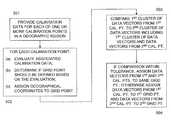
- an embodiment of the present subject matterprovides a method for assigning geographical coordinates to a grid point located in a geographic region for the location of a mobile device where the method provides calibration data for each of one or more calibration points in the geographic region and where for each of the calibration points the associated calibration data is evaluated and based on that evaluation a determination is made as to whether at least one grid point should be defined, and if so, geographical coordinates are assigned to the grid point.
- An additional embodiment of the present subject matterfurther includes in the above method a determination of geographical coordinates for each of a plurality of nodes of a uniform grid spanning the geographic region and for each of the grid points determining a closest node from the plurality of nodes and assigning characteristic data associated with the grid point to the closest node.
- a further embodimentincludes a method of assigning geographical coordinates to a grid point located in a geographic region for the location of a mobile device where calibration data for each of one or more calibration points in the geographic region are provided, and where for the calibration data associated with each of the calibration points the calibration data is evaluated, a determination is made based on the evaluation as to whether at least one grid point should be defined, and geographical coordinates are assigned to the grid point.
- a system for assigning geographical coordinates to a grid point located in a geographic regionwhere the system includes a database and a processor for receiving calibration data for each of one or more calibration points in the geographic region and for each of the calibration points the processor is programmed to evaluate the associated calibration data, determine if at least one grid point should be defined based on the evaluation, assign geographical coordinates to the at least one grid point, and populate the database with the geographical coordinates.
- a further embodiment of the present subject matterincludes in the above system circuitry for determining geographical coordinates for each of a plurality of nodes of a uniform grid spanning the geographic region, and circuitry for determining, for each of the at least one grid point, a closest node from the plurality of nodes and assigning characteristic data associated with the grid point to the closest node.
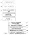
- Yet another embodiment of the present subject matterprovides a method of locating a mobile device.
- the methodcomprises the steps of providing a plurality of grid points in a geographic region, providing a plurality of network measurement reports for a mobile device in the geographic region, and comparing ones of the plurality of grid points to at least one parameter of ones of the plurality of network measurement reports.
- the methodfurther includes generating a first location estimate of the mobile device for each of the ones of said plurality of network measurement reports, and determining a second location estimate of the mobile device as a function of at least one of the generated first location estimates.
- An additional embodimentincludes the step of identifying and omitting outlier first location estimates by determining a Mahalanobis distance from each first location estimate to the second location estimate, determining a distance threshold from a median of the Mahalanobis distances multiplied by a predetermined factor, and determining a third location estimate by averaging two or more of said first location estimates. Another embodiment may also interpolate between ones of the plurality of grid points when more than one grid point corresponds to the at least one parameter of the plurality of network measurement reports. An additional embodiment may provide a default location for the second location estimate if a second location estimate cannot be determined as a function of at least one of the generated first location estimates.
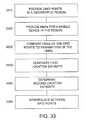
- An additional embodiment of the present subject matterprovides a method of improving a location estimate of a mobile device.
- the methodcomprises the steps of providing a plurality of grid points in a geographic region, providing a set of network measurement reports for a mobile device in the geographic region, the set of network measurement reports including one or more subsets of network measurement reports, and comparing ones of the plurality of grid points to at least one parameter of a subset of the network measurement reports.
- the methodfurther includes generating a first location estimate of the mobile device for each subset of network measurement reports, determining a second location estimate of the mobile device as a function of at least one of the generated first location estimates, and indicating an attribute of the second location estimate as a function of a parameter of a subset of the network measurement reports.
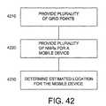
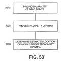
- Another embodiment of the present subject matterprovides a method of locating a mobile device in a geographic region.
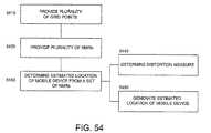
- the methodcomprises the steps of providing a plurality of grid points in a geographic region, each of the grid points including at least one characterizing parameter and each of the grid points located on a grid defined over the geographic region and providing a plurality of network measurement reports for a mobile device in the geographic region.
- the methodalso comprises determining an estimated location for the mobile device from one network measurement report as a function of the at least one parameter.
- An additional embodiment of the present subject matterprovides a method of locating a mobile device in a geographic region.
- the methodcomprises the steps of providing a plurality of grid points in a geographic region, each of the grid points including at least one characterizing parameter and each of the grid points located on a grid defined over the geographic region and providing a plurality of network measurement reports for a mobile device in the geographic region.
- the methodalso comprises determining an estimated location for the mobile device from a set of said plurality of network measurement reports as a function of the parameter.
- Yet another embodiment of the present subject matterprovides another method of estimating the location of a mobile device in a geographic region.
- the methodcomprises the steps of providing calibration data for each of one or more calibration points in a geographic region where the calibration data includes at least one characterizing parameter.
- a candidate network measurement report or set of network measurement reportsmay be received from a mobile device at an unknown location, where the network measurement report also includes at least one characterizing parameter.
- the methodfurther comprises defining a first region as a function of a first characterizing parameter and a predetermined range of said first parameter.
- a second regionmay be defined as a function of another characterizing parameter and a predetermined range of another parameter.
- a method of estimating the location of a mobile device in a geographic regionmay comprise the steps of providing one or more sets of calibration data for a plurality of calibration points in a geographic region where the calibration data includes at least one characterizing parameter and for each of select ones of the calibration points the calibration data includes plural data vectors.
- the methodmay also include receiving a candidate network measurement report or set of network measurement reports from a mobile device at an unknown location, where the network measurement report also includes at least one characterizing parameter.
- the methodalso includes defining a first region as a function of a first characterizing parameter and a predetermined range of the first parameter for a select one set of calibration data, and for the set of calibration data, defining a second region as a function of another characterizing parameter and a predetermined range of the another parameter. These steps may be repeated for each characterizing parameter in the set of calibration data and a clustering of the plural data vectors may be determined. The location of a mobile device may be estimated in the geographic region as a function of the clustering.
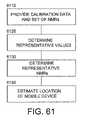
- Another embodiment of the present subject matterprovides a method of estimating the location of a mobile device in a geographic region comprising providing calibration data for each of one or more calibration points in a geographic region where the calibration data includes at least one characterizing parameter and receiving a set of network measurement reports from a mobile device at an unknown location where at least one of the network measurement reports in the set also includes at least one characterizing parameter.
- the methodmay also comprise determining a representative value for each available characterizing parameter in the set as a function of a variation of the available characterizing parameter in each network measurement report in the set and determining one or more representative network measurement reports as a function of the representative value.
- the methodmay then estimate the location of a mobile device in the geographic region as a function of the one or more representative network measurement reports.
- One embodiment of the present subject matterprovides a system for estimating the location of a mobile device in a geographic region comprising a database and a processor for receiving calibration data for each of one or more calibration points in a geographic region, the calibration data having at least one characterizing parameter and receiving a candidate network measurement report or set of network measurement reports from a mobile device at an unknown location, where the network measurement report also includes at least one characterizing parameter.
- the processormay be programmed to determine a first region as a function of a first characterizing parameter and a predetermined range of the first parameter and repeat the determination for each characterizing parameters in the calibration data.
- the processormay be further programmed to determine an intersection for each defined region, and estimate the location of a mobile device in the geographic region as a function of the intersection.
- Another embodiment of the present subject matterprovides a system for estimating the location of a mobile device in a geographic region comprising a database and a processor for receiving calibration data for each of one or more calibration points in a geographic region where the calibration data may include at least one characterizing parameter.
- the processormay also receive a set of network measurement reports from a mobile device at an unknown location, at least one of the network measurement reports in the set may also include at least one characterizing parameter.
- the processormay be programmed to determine a representative value for each available characterizing parameter in the set as a function of a variation of the available characterizing parameter in each network measurement report in the set, determine one or more representative network measurement reports as a function of the representative value, and estimate the location of a mobile device in the geographic region as a function of the one or more representative network measurement reports.
- FIG. 1is a flow chart for a method for assigning geographical coordinates according to an embodiment of the present subject matter.
- FIG. 2is a flow chart for a method for assigning geographical coordinates including a calibration point according to an embodiment of the present subject matter.
- FIG. 3is a flow chart for a method for assigning geographical coordinates including calibration data according to an embodiment of the present subject matter.
- FIG. 4is a flow chart for a method for assigning geographical coordinates including clustering of data according to an embodiment of the present subject matter.
- FIG. 5is a flow chart for a method for assigning geographical coordinates including clustering of data vectors according to an embodiment of the present subject matter.
- FIG. 6is a flow chart for a method for assigning geographical coordinates including clustering according to an embodiment of the present subject matter.
- FIG. 7is a flow chart for a method for assigning geographical coordinates including determining outliers according to an embodiment of the present subject matter.
- FIG. 8is a flow chart for a method for assigning geographical coordinates including clustering of data vectors at the same calibration point according to an embodiment of the present subject matter.
- FIG. 9is a flow chart for a method for assigning geographical coordinates including clustering of data vectors at the same calibration point according to an embodiment of the present subject matter.
- FIG. 10is a flow chart for a method for assigning geographical coordinates to a grid point according to an embodiment of the present subject matter.
- FIG. 11is a flow chart for a method for assigning geographical coordinates including assigning geographical coordinates to a grid point where only one calibration point is in a geographic region according to an embodiment of the present subject matter.
- FIG. 12is a flow chart for a method for assigning geographical coordinates including assigning geographical coordinates to a grid point where there are plural calibration points in a geographic region according to an embodiment of the present subject matter.
- FIG. 13is a flow chart for a method for assigning geographical coordinates including calibration data information according to an embodiment of the present subject matter.
- FIG. 14is a flow chart for a method for assigning geographical coordinates including evaluating calibration data according to an embodiment of the present subject matter.
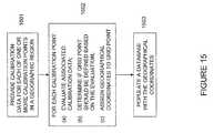
- FIG. 15is a flow chart for a method for assigning geographical coordinates including populating a database with the geographical coordinates according to an embodiment of the present subject matter.
- FIG. 16is a flow chart for a method for assigning geographical coordinates including database information according to an embodiment of the present subject matter.
- FIG. 17is a flow chart for a method for assigning geographical coordinates including determining geographical coordinates for nodes of a uniform grid according to an embodiment of the present subject matter.
- FIG. 18is a flow chart for a method for assigning geographical coordinates including characteristic data to nodes of uniform grid according to an embodiment of the present subject matter.
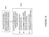
- FIG. 19is a flow chart for a method for assigning geographical coordinates for calibration data for each of one or more calibration points in a geographic region according to an embodiment of the present subject matter.
- FIG. 20is a block diagram for a system for assigning geographical coordinates according to an embodiment of the present subject matter.
- FIG. 21is a block diagram for a system for assigning geographical coordinates including a determination of clustering of plural data vectors according to an embodiment of the present subject matter.
- FIG. 22is a block diagram for a system for assigning geographical coordinates including comparing clusters of data vectors from different calibration points according to an embodiment of the present subject matter.
- FIG. 23is a block diagram for a system for assigning geographical coordinates including comparing clusters of data vectors from the same calibration point according to an embodiment of the present subject matter.
- FIG. 24is a block diagram for a system for assigning geographical coordinates including calibration data according to an embodiment of the present subject matter.
- FIG. 25is a block diagram for a system for assigning geographical coordinates including evaluating calibration data according to an embodiment of the present subject matter.
- FIG. 26is a block diagram for a system for assigning geographical coordinates including information for populating a database according to an embodiment of the present subject matter.
- FIG. 27is a block diagram for a system for assigning geographical coordinates including circuitry for determining geographical coordinates for nodes of a uniform grid according to an embodiment of the present subject matter.
- FIG. 28is a block diagram for a system for assigning geographical coordinates including characteristic data according to an embodiment of the present subject matter.
- FIG. 29is a flow chart for a method for locating a mobile device according to one embodiment of the present subject matter.
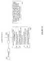
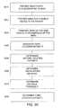
- FIG. 30is a flow chart for a method for locating a mobile device according to one embodiment of the present subject matter including identifying and omitting outlier first location estimates.
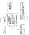
- FIG. 31is a flow chart for a method for locating a mobile device according to another embodiment of the present subject matter.
- FIG. 32is a flow chart for a method for locating a mobile device according to one embodiment of the present subject matter including omitting a first location estimate.
- FIG. 33is a flow chart for a method for locating a mobile device according to one embodiment of the present subject matter including interpolating between grid points.
- FIG. 34is a flow chart for a method for locating a mobile device according to another embodiment of the present subject matter including interpolating between grid points and/or assigning weights to selected grid points.
- FIG. 35is a flow chart for a method for locating a mobile device according to another embodiment of the present subject matter including providing a default location.
- FIG. 36is a flow chart for a method of improving a location estimate of a mobile device.
- FIG. 37is a flow chart for a method of improving a location estimate of a mobile device according to another embodiment of the present subject matter.
- FIG. 38is a flow chart for a method of improving a location estimate of a mobile device according to another embodiment of the present subject matter including omitting a first location estimate.
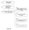
- FIG. 39is a flow chart for a method for locating a mobile device according to one embodiment of the present subject matter including identifying and omitting outlier first location estimates.
- FIG. 40is a flow chart for a method of improving a location estimate of a mobile device according to a further embodiment of the present subject matter.
- FIG. 41is a flow chart for a method of improving a location estimate of a mobile device according to a further embodiment of the present subject matter including providing a default location.
- FIGS. 42-55are flow charts for methods of locating a mobile device in a geographic region according embodiments of the present subject matter.
- FIGS. 56-64are flow charts for methods of estimating the location of a mobile device in a geographic region according to embodiments of the present subject matter.
- FIGS. 65-66are diagrams for systems for estimating the location of a mobile device in a geographic region according to embodiments of the present subject matter.
- the present subject matteris directed generally to the problem of estimating the location of a wireless mobile device using calibration data contained in one or more Network Measurement Reports (“NMRs”).
- NMRsNetwork Measurement Reports
- the calibration data for various pointsmust be gathered and analyzed so that particular points (e.g., “grid points”) within the geographic region can be determined and associated with a particular set or sets of calibration data from, for example, one or more NMRs.
- geographic coordinatesmay be assigned to grid points located in a geographic region.
- the grid pointsmay be non-uniformly spaced throughout the geographic region and hence may be referred to as non-uniform grid points (“NUGs”).
- NUGsnon-uniform grid points
- the location of a wireless mobile devicemay be estimated by comparing data reported by the mobile device to be geolocated with the data (and more particularly the characteristics derived from this data) associated with the various grid points to thereby estimate the location of the mobile.
- the system and/or method of the present subject mattermay apply to the situation where calibration data is available over discrete points in a 2-dimensional region “R” (3-D region is also contemplated such as within large multi-level structures).
- the calibration datamay be contained within a Network Measurement Report (“NMR”) as is known in the art or the calibration data may be obtained using other known methods.
- NMRNetwork Measurement Report
- the calibration datamay be obtained at each of several calibration points, which may be discrete points within region R each having geographical coordinates (e.g., latitude and longitude) associated therewith.
- the calibration datamay include, but is not limited to, the following: (a) signal strengths observed for signals transmitted by a set of transmitters of known location within or in proximity to the region R; (b) signal strength of a transmitter located at the calibration point as measured by a set of receivers of known location within or in proximity to the region R; (c) round trip time for a signal between the calibration point and an external known point; (d) time difference of arrival at the calibration point with respect pairs of external points located within or in proximity to region R as measured by either a receiver at the calibration point or the external points; (e) the serving cell or sector for a mobile wireless device operating at that calibration point; (f) the network state at the time of collection—a finite number of such states may be required to distinguish between network conditions that vary diurnally, weekly or in some other manner; and (g) combinations of the above.
- the case in (a)may apply to the Integrated Digital Enhanced Network (“IDEN”) specification
- (c)may apply to the Global System for Mobile communications (“GSM”) specification as in the Timing Advance (“TA”) parameter or the Round Trip Time (“RTT”) parameter in the Universal Mobile Telecommunications System (“UMTS”) specification
- (d)may apply to the UMTS specification
- the external receiversmay be the base stations.
- the calibration datamay be any of those measurements made by a mobile wireless device located at the calibration point or any measurement made on the transmissions or characteristics of the mobile wireless device at a set of external transmitter/receivers in the region R or in proximity thereto.
- the calibration datamay consist of many such sets (i.e., vectors) obtained at one or more calibration points.
- the data gatheringmay have resulted in either a single data vector or multiple data vectors, so that there are potentially multiple sets of data and/or data vectors associated with each calibration point.
- a NUG generator or a method to produce NUGsmay begin the NUG generation operation using, for example, one of more of the following: (a) a fixed uniform grid (“UG”) defined over the region R with the calibration point data being assigned to the fixed grid points by some rule (e.g., allocated by closest fixed grid point, a centroid of a set of fixed grid points, etc.); (b) random grid points to define the start of each NUG; (c) combinations of (a) and (b) depending on the characteristics of the calibration data; or (d) some other useful method.
- UGuniform grid
- the NUG generatormay evaluate the data vectors at a particular (candidate) calibration point, or at a fixed grid point to which the data vector(s) is/are assigned.
- This calibration point or grid pointmay serve as the root of a first NUG.
- the root of the NUGmay be the calibration data vector that initiates the creation of that NUG.
- the vectorsmay be examined using, for example, increasingly stringent tests of statistical sufficiency. In particular, a determination may be made as to whether the data vectors exhibit clustering. If the data exhibits tight clustering, the data for the next candidate calibration point may be aggregated to the former calibration point and the clustering property may be re-evaluated.
- the second calibration pointalso has a cluster but this cluster is sufficiently different than the cluster of the first calibration point
- a determinationmay be made that the data for the two considered calibration points should be allocated to the roots of separate NUGs.
- the aggregate clusteri.e., a cluster including data from both the first and second calibration points
- the data for the two calibration pointsmay be allocated to the same NUG.
- All adjacent calibration data pointsmay be similarly evaluated with respect to the first considered calibration point. Thus one or more of the adjacent calibration points may either wind up having all their data accumulated into a single NUG or, at the other extreme, each such calibration point may become the root of a separate NUG.
- the primary test made to determine the allocationmay be one of a variety of clustering tests, such as, for example, the K-means algorithm.
- Statistical similaritymay be determined by, for example, the probability density function (“pdf”) of the data parameters (e.g., neighboring cell signal levels, timing information, etc.), the mean and variance of the data parameters, the serving cell/sector, or other functions of the calibration data.
- PDFprobability density function
- Those measurements or parameter values that do not clustermay be referred to as outliers.
- the performance of a grid-based pattern matching system such as that disclosed hereinis typically dependent on stored received signal level measurements that accurately reflect the levels that are likely to be reported by the mobile device to be located. If the drive test data, for example, used to create the RF signal level grid contains outlier measurements, the statistically consistent value of the signal level will be distorted. Therefore, the present subject matter also describes a system and method used to identify and eliminate outlier signal level measurements and timing advance values (or in general, any parameter within the NMR) during NUG or grid creation so as to improve the estimate of the mean parameter value.
- neighbor cell control channel signal level measurement outlierscould be eliminated as follows: At each grid point, the average received signal level of a particular control channel signal may be computed from all of the measurements of that signal assigned to the grid point. The deviation of each individual measurement from the mean may be computed. Measurements that deviate by more than a configurable predetermined threshold from the mean may be omitted. The average may then be recomputed without the omitted outliers.
- the original mean valuewill be greatly influenced by any outlier measurements and thus may falsely identify too many of the measurements as outliers, or fail to detect outliers at all. For this reason, another parameter is used to only perform the outlier check if there are at least a minimum number of measurements.
- a clustermay be a region in N-dimensional NMR vector space where there is a sufficient number of such vectors with a mutual variation such that the mutual variation could be ascribed purely to noise in the measurement.
- a particular parameteris blocked (say by a large structure such as a building) that parameter would fall out of the original cluster. If sufficient such blocked locations have data falling near the original cluster, one may obtain a secondary cluster where the difference between the first and second clusters is the large variation in this particular parameter.
- any of the examined sets of data associated with a calibration pointexhibit more than one cluster, it may be necessary to define one or more co-located NUGs.
- these clusterscould form the roots of three co-located NUGs.
- the data in these NUGsmay grow depending on whether similar clusters can also be found in adjacent (or close) calibration points in which case the similar clusters may be aggregated to the original NUGs or, if the adjacent clusters are not similar, the adjacent clusters (or cluster) may form separate root NUGs (or NUG).
- data from adjacent calibration grid pointsmay be accumulated first and the statistical or clustering test performed thereafter.
- the determination of how one should separate out the data into NUGsmay be made.
- the techniquemay be repeated until all calibration grid points in the region R are exhausted.
- the NUGsmay fully cover the region R and each NUG may have statistically similar data accumulated into itself.
- the geometrical shapei.e., the shape defined by the union of locations of calibration points assigned to the NUG
- the amount of data accumulated into such NUGsis seen to be variable since these are determined by the statistical similarity of the data allocated to a NUG.
- NUGsbased not on statistical consistency of calibration data, but on other conditions such as (a) a minimum number of unique neighbors observed in data accumulated from allocated calibration grid points; (b) a minimum number of data vectors (NMRs); (c) a maximum and/or minimum NUG radius; (d) a specific set of neighboring cells; (e) a specific set of neighboring cells with power ordering; or (f) any combination of the above. Additionally, the method of using statistical consistency or similarity or data clustering combined with any of these other conditions may be employed.
- NUG characteristicsare a representation in that attempt to capture the nature and variability of the data associated with that NUG in a compact and representative form.
- These characteristicsmay include, but are not limited to, the following: (a) an ordered list of neighboring cells; (b) functions defined on the absolute neighboring cell power levels (e.g., mean, median, k th moment, cluster-mean, etc.); (c) functions defined on the relative neighboring cell power differences (e.g., mean, median, k th moment, cluster-mean, etc.); (d) serving cell/sector; (e) timing advance parameter (or equivalent); (f) individual pdf (probability density function or probability distribution function) of each neighboring cell power level; (g) joint pdf of neighboring cell power levels; (h) mean and variance of neighboring cell power levels; (i) mobile device orientation (e.g., indoors, outdoors, direction mobile device is facing (e.g., North, South, etc.), tilted upwards, azimuth, elevation, etc.); (j) a compact and/or efficient representation that enables retrieval of the calibration data NMR vectors assigned to this NUG; (k) the network state
- a pdfmay be generated using either the Parzen technique or the method of Gaussian mixtures or some variant thereof.
- that parametermay be set to a value dependent on the observed variance for a particular neighboring cell power level or the observed covariance matrix for a set of neighboring cell power levels.
- the location ascribed to the NUGmay be, for example, any internal point within the NUG. If the NUG contains only a single calibration point, the location of the NUG may be set as the location of the calibration point. If the NUG encompasses several calibration points, the location of any one of the calibration points or the centroid of such calibration points or some other similar measure may be used to define the NUG location. Also, in the case of multiple co-located NUGs, all such NUGs may have their assigned location set to the same value.
- calibration datamay be provided for each of one or more calibration points in a geographic region.
- calibration data associated with the calibration pointis evaluated and a determination is made as to whether a grid point, such as a NUG, should be defined. If it is determined that a grid point is to be defined, geographical coordinates are assigned to the grid point so that the grid point may be useful in estimating the location of a mobile device.
- FIG. 2is a flow chart for a method for assigning geographical coordinates including a calibration point according to an embodiment of the present subject matter.
- Blocks 201 and 202are similar to blocks 101 and 102 , respectively.
- the calibration pointmay be located on a predetermined fixed uniform grid defined over the geographic region or the calibration point may be randomly located within the geographic region.
- FIG. 3is a flow chart for a method for assigning geographical coordinates including calibration data according to an embodiment of the present subject matter.
- Blocks 301 and 302are similar to blocks 101 and 102 , respectively.
- the calibration data associated with one or more calibration pointsmay be comprised of information from a NMR, or the calibration data for a particular calibration point may be obtained from one or more mobile devices located at or in close proximity to the calibration point, or the calibration data for a particular calibration point may be obtained from a signal transmitted from a mobile device (or devices) located at or in close proximity to the calibration point where the signal is received by a receiver in or in proximity to the geographic region.
- FIG. 4is a flow chart for a method for assigning geographical coordinates including clustering of data according to an embodiment of the present subject matter.
- Blocks 401 and 402are similar to blocks 101 and 102 , respectively.
- the calibration datamay include multiple data vectors and, at block 414 , the evaluation of the data vectors may include a determination of clustering of the multiple data vectors as described above.
- Blocks 501 and 502are similar to blocks 101 and 102 , respectively.
- the determination of whether at least one grid point should be defined based on the evaluation of the calibration data associated with a calibration pointincludes a comparison of a first cluster of data vectors from a first calibration point to a second cluster of data vectors where the second cluster of data vectors includes the first cluster of data vectors as well as data vectors from a second calibration point.
- the comparison in block 503results in the difference between the first and second cluster of data vectors being within a predetermined tolerance value, then the data vectors from the first and second calibration points are assigned to the same grid point. However, if the comparison is not within tolerance, then the data vectors from the first calibration point are assigned to a first grid point and the data vectors from the second calibration point are assigned to a second grid point.
- the flow chart shown in FIG. 6illustrates another method for assigning geographical coordinates including clustering according to an embodiment of the present subject matter.
- blocks 601 , 602 , 603 , and 604are similar to blocks 501 , 502 , 503 , and 504 , respectively.
- the evaluation of calibration data for one or more calibration pointsmay include determining the clustering of plural data vectors using a K-means analysis.
- the comparing of clusters of data vectorsmay include determining a probability density function of an aspect of the data vectors.
- FIG. 7is a flow chart for a method for assigning geographical coordinates including determining outliers according to an embodiment of the present subject matter.
- Blocks 701 , 702 , 713 , and 714are similar to blocks 401 , 402 , 413 , and 414 , respectively.
- a determination of outlier data vectorsmay be made and the outlier data vectors may be eliminated from the determination of data vector clustering.
- a flow chartis represented for a method for assigning geographical coordinates including clustering of data vectors at the same calibration point according to an embodiment of the present subject matter.
- Blocks 801 and 802are similar to blocks 101 and 102 , respectively.
- the determination if at least one grid point should be defined based on the evaluation of calibration datamay include a comparison of a first cluster of data vectors associated with a first calibration point to a second cluster of data vectors associated with the first calibration point.
- the data vectors from the first and second clustersmay be assigned to the same grid point; otherwise, the data vectors from the first cluster may be assigned to a first grid point while the data vectors from the second cluster may be assigned to a second grid point.
- FIG. 9is a flow chart illustrating another method for assigning geographical coordinates including clustering of data vectors at the same calibration point according to an embodiment of the present subject matter.
- blocks 901 , 902 , 903 , and 904are similar to blocks 801 , 802 , 803 , and 804 , respectively.
- the geographical coordinates assigned to the first and second grid pointsmay be identical.
- Blocks 1001 and 1002are similar to blocks 101 and 102 , respectively.
- the geographical coordinates assigned to a first grid pointmay be different than the geographical coordinates assigned to a second grid point or the geographical coordinates assigned to a first grid point may be the same as the geographical coordinates assigned to a second grid point.
- FIG. 11is a flow chart for a method for assigning geographical coordinates including assigning geographical coordinates to a grid point where only one calibration point is in a geographic region according to an embodiment of the present subject matter.
- Blocks 1101 and 1102are similar to blocks 101 and 102 , respectively.
- the geographical coordinates assigned to a grid pointmay result in the grid point being located within a predetermined radius of the one calibration point.
- the geographical coordinates assigned to a grid pointmay be identical to the geographical coordinates of the calibration point.
- FIG. 12a flow chart is shown for a method for assigning geographical coordinates including assigning geographical coordinates to a grid point where there are plural calibration points in a geographic region according to an embodiment of the present subject matter.
- Blocks 1201 and 1202are similar to blocks 101 and 102 , respectively.
- the geographical coordinates assigned to a grid pointmay result in the grid point being located within a predetermined radius of a centroid of a polygon formed by connecting the multiple calibration points.
- FIG. 13is a flow chart for a method for assigning geographical coordinates including calibration data information according to an embodiment of the present subject matter.
- Blocks 1301 and 1302are similar to blocks 101 and 102 , respectively.
- the calibration datamay include one or more of the following: signal strength for a signal transmitted by a transmitter having a known location as received by a receiver at a calibration point; signal strength of a signal transmitted by a transmitter located at a calibration point as received by a receiver at a known location; round trip time for a signal traveling between a calibration point and a known location; timing advance of a signal received by a mobile device at a calibration point; time difference of arrival of plural signals at a calibration point with respect to a pair of known locations as measured by a receiver at a calibration point or at the known locations; the identification of a serving cell or serving sector of a mobile device located at a calibration point; a state of a wireless network serving a mobile device, and combinations thereof.
- FIG. 14is a flow chart for a method for assigning geographical coordinates including evaluating calibration data according to an embodiment of the present subject matter.
- Blocks 1401 and 1402are similar to blocks 101 and 102 , respectively.
- the evaluating of the calibration data associated with a calibration pointmay include an evaluation such as: a minimum number of unique neighboring calibration points as determined by calibration data of the neighboring calibration points; a minimum number of data vectors or network measurement reports; a predetermined maximum or minimum radius from a calibration point; a predetermined set of cells neighboring a cell serving a mobile device; and combinations thereof.
- FIG. 15is a flow chart for a method for assigning geographical coordinates including populating a database with the geographical coordinates according to an embodiment of the present subject matter.
- Blocks 1501 and 1502are similar to blocks 101 and 102 , respectively.
- a databasemay be populated with the geographical coordinates assigned to the grid points.
- FIG. 16is a flow chart for a method for assigning geographical coordinates including database information according to an embodiment of the present subject matter.
- Blocks 1601 , 1602 , and 1603are similar to blocks 1501 , 1502 , and 1503 , respectively.
- the databasemay be populated with information such as: a list of cells neighboring a cell serving a mobile device; a quantity that is a function of a power level of one or more cells neighboring a cell serving a mobile device; an identity of a cell or a sector serving a mobile device; a timing advance parameter; a geographical orientation of a mobile device; a location of a mobile device; network measurement report data vectors; a state of a network serving a mobile device; a confidence measure indicative of a reliability of the calibration data; and combinations thereof.
- FIG. 17a flow chart is presented for a method for assigning geographical coordinates including determining geographical coordinates for nodes of a uniform grid according to an embodiment of the present subject matter.
- Blocks 1701 and 1702are similar to blocks 101 and 102 , respectively.
- geographical coordinatesmay be determined for the nodes of a uniform grid spanning the geographic region.
- block 1704for each of the grid points, a determination of the closest node of the uniform grid is made and the characteristic data associated with the grid point may be assigned to the closest node.
- FIG. 18is a flow chart for a method for assigning geographical coordinates including characteristic data to nodes of uniform grid according to an embodiment of the present subject matter.
- blocks 1801 , 1802 , 1803 , and 1804are similar to blocks 1701 , 1702 , 1703 , and 1704 , respectively.
- the characteristic datamay include a list of cells neighboring a cell serving a mobile device; a quantity that is a function of a power level of one or more cells neighboring a cell serving a mobile device; an identity of a cell or a sector serving a mobile device; a timing advance parameter; a geographical orientation of a mobile device; a location of a mobile device; network measurement report data vectors; a state of a network serving a mobile device; a confidence measure indicative of a reliability of the calibration data; and combinations thereof.
- a flow chartis illustrated for a method for assigning geographical coordinates for calibration data for each of one or more calibration points in a geographic region according to an embodiment of the present subject matter.
- calibration datamay be provided for each of one or more calibration points in a geographic region.
- the calibration datais evaluated and a determination is made as to whether a grid point should be defined based on the evaluation. If it is determined that a grid point is to be defined, geographical coordinates are assigned to the grid point so that the grid point may be useful in estimating the location of a mobile device.
- a database 2001is operatively connected to a processor 2002 .
- the processor 2002is capable of receiving calibration data for each of one or more calibration points in a geographic region.
- the processor 2002may be programmed, as shown in block 2003 , to evaluate the calibration data associated with the calibration points, determine if at least one grid point should be defined based on the evaluation, assign geographical coordinates to the one or more grid points, and populate the database 2001 with the geographical coordinates.
- FIG. 21is a block diagram for a system for assigning geographical coordinates including a determination of clustering of plural data vectors according to an embodiment of the present subject matter.
- the database 2101 , the processor 2102 , and block 2103are similar to the database 2001 , the processor 2002 , and block 2003 , as described above, respectfully.
- the calibration datamay include multiple data vectors and the evaluating of the calibration data may include a determination of clustering of the multiple data vectors.
- FIG. 22is a block diagram for a system for assigning geographical coordinates including comparing clusters of data vectors from different calibration points according to an embodiment of the present subject matter.
- the database 2201 , the processor 2202 , block 2203 , and block 2214are similar to the database 2101 , the processor 2102 , block 2103 , and block 2114 , as described above, respectfully.
- the determination if at least one grid point should be defined based on the evaluationmay include comparing a first cluster of data vectors from a first one of the select calibration points to a second cluster of data vectors, where the second cluster of data vectors may include the first cluster of data vectors and data vectors from a second one of the select calibration points.
- the data vectors from the first and second calibration pointsmay be assigned to the same grid point; otherwise, the data vectors from the first calibration point may be assigned to a first grid point and the data vectors from the second calibration point may be assigned to a second grid point.
- FIG. 23is a block diagram for a system for assigning geographical coordinates including comparing clusters of data vectors from the same calibration point according to an embodiment of the present subject matter.
- the database 2301 , the processor 2302 , block 2303 , and block 2314are similar to the database 2101 , the processor 2102 , block 2103 , and block 2114 , as described above, respectfully.
- the determination if at least one grid point should be defined based on the evaluationmay include comparing a first cluster of data vectors from a first one of the select calibration points to a second cluster of data vectors from the first one of the select calibration points.
- the data vectors from the first and second calibration pointsmay be assigned to the same grid point; otherwise, the data vectors from the first cluster may be assigned to a first grid point and the data vectors from the second cluster may be assigned to a second grid point.
- FIG. 24a block diagram is presented representing a system for assigning geographical coordinates including calibration data according to an embodiment of the present subject matter.
- the database 2401 , the processor 2402 , and block 2403are similar to the database 2001 , the processor 2002 , and block 2003 , as described above, respectfully.
- the calibration datamay include: signal strength for a signal transmitted by a transmitter having a known location as received by a receiver at a calibration point; signal strength of a signal transmitted by a transmitter located at a calibration point as received by a receiver at a known location; round trip time for a signal traveling between a calibration point and a known location; timing advance of a signal received by a mobile device at a calibration point; time difference of arrival of multiple signals at a calibration point with respect to a pair of known locations as measured by a receiver at a calibration point or at the known locations; the identification of a serving cell or serving sector of a mobile device located at a calibration point; a state of a wireless network serving a mobile device, and combinations thereof.
- FIG. 25is a block diagram for a system for assigning geographical coordinates including evaluating calibration data according to an embodiment of the present subject matter.
- the database 2501 , the processor 2502 , and block 2503are similar to the database 2001 , the processor 2002 , and block 2003 , as described above, respectfully.
- the evaluation of the associated calibration datamay include an evaluation such as: a minimum number of unique neighboring calibration points as determined by calibration data of the neighboring calibration points; a minimum number of data vectors or network measurement reports; a predetermined maximum or minimum radius from a calibration point; a predetermined set of cells neighboring a cell serving a mobile device; and combinations thereof.
- FIG. 26is a block diagram for a system for assigning geographical coordinates including information for populating a database according to an embodiment of the present subject matter.
- the database 2601 and the processor 2602are similar to the database 2001 and the processor 2002 , as described above, respectfully.
- the processor 2602may be programmed to evaluate the calibration data associated with the calibration points, determine if at least one grid point should be defined based on the evaluation, assign geographical coordinates to the one or more grid points, populate the database 2601 with the geographical coordinates, and populate the database 2601 with information which may include: a list of cells neighboring a cell serving a mobile device; a quantity that is a function of a power level of one or more cells neighboring a cell serving a mobile device; an identity of a cell or a sector serving a mobile device; a timing advance parameter; a geographical orientation of a mobile device; a location of a mobile device; network measurement report data vectors; a state of a network serving a mobile device; a confidence measure indicative of a reliability of the calibration data; and combinations thereof.
- FIG. 27is a block diagram for a system for assigning geographical coordinates including circuitry for determining geographical coordinates for nodes of a uniform grid according to an embodiment of the present subject matter.
- the database 2701 , the processor 2702 , and block 2703are similar to the database 2601 , the processor 2602 , and block 2603 , as described above, respectfully.
- the systemmay further comprise circuitry 2704 for determining geographical coordinates for each of a plurality of nodes of a uniform grid spanning the geographic region, and circuitry 2705 for determining, for each of the one or more grid points, a closest node from the plurality of nodes of the uniform grid and assigning characteristic data associated with each of the grid point to its closest node.
- FIG. 28is a block diagram for a system for assigning geographical coordinates including characteristic data according to an embodiment of the present subject matter.
- the database 2801 , the processor 2802 , block 2803 , circuitry 2804 , and circuitry 2805are similar to the database 2701 , the processor 2702 , block 2703 , circuitry 2704 , and circuitry 2705 , as described above, respectfully.
- the characteristic datamay include: a list of cells neighboring a cell serving a mobile device; a quantity that is a function of a power level of one or more cells neighboring a cell serving a mobile device; an identity of a cell or a sector serving a mobile device; a timing advance parameter; a geographical orientation of a mobile device; a location of a mobile device; network measurement report data vectors; a state of a network serving a mobile device; a confidence measure indicative of a reliability of the calibration data; and combinations thereof.
- the time allowed to produce a locationmay be such that multiple NMRs and sets and subsets thereof may be available.
- mobile measurementsare reported at an approximate rate of approximately two per second.
- the time allowed to produce a locationmay be on the order of thirty seconds. It is therefore an aspect of embodiments of the present subject matter to improve location accuracy by combining individual locations from calibration data, e.g., multiple NMRs, to produce a final location estimate.
- Grid-based signal strength pattern matching location systemstypically determine a quantitative measure of how close each candidate grid point matches with mobile-reported measurement parameters. An estimate of a mobile device's location may then be given by a grid point having the closest match thereto or a location interpolated between several grid point locations. As multiple NMRs are generally available during the time allotted to report the estimated location of a mobile device, embodiments of the present subject matter may utilize each NMR to generate an independent location estimate. These independent or individual location estimates may then be averaged or another mathematical function employed thereon to produce a final estimated mobile location that may be statistically more accurate.
- a location status variablemay be utilized to identify the default location as a fall back location.
- a fall back locationis generally less accurate than a location estimate determined by a pattern matching location system; however, an exemplary location combiner may omit any fall back locations and average or combine location estimates determined by an exemplary pattern matching algorithm.
- a correlationmay exist between location accuracy and mismatch distance metrics, e.g., “cost” values.
- the correlationmay be exploited by flagging individual location estimates as having a high cost or metric (e.g., using a location status variable), and the corresponding location estimates are likely to possess a large location error.
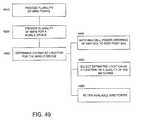
- Embodiments of the present subject mattermay present a refinement to the location combiner by skipping or omitting individual locations exceeding a predetermined “cost” threshold. Thus, the resulting location accuracy may be significantly improved.
- the correlation between mismatch distance metrics and location accuracymay be exploited by employing weighted averaging of the individual estimated locations, weighting by an inverse of the metrics, normalizing by a sum of the inverses, or any combination thereof.
- a further metric that may be utilized for weighting the contribution of individual location estimates to a final location estimatemay be the number of reporting neighboring cells.
- the fifth location estimatemay then be de-weighted in the final location estimation.
- Another embodiment of the present subject mattermay identify and omit outlier individual location estimates to improve the final location estimation. For example, a Mahalanobis distance from each individual location estimate to the final location estimate may be determined. A dynamic distance threshold may be determined from the median of these distances multiplied by a configurable factor. An individual location estimate having a distance to the final location estimate exceeding the threshold may be identified as an outlier. The final location estimate may then be re-determined with the outlier locations omitted. In the event that weighted averaging is utilized in such a determination, the weights may be re-determined prior to the final location estimation.
- NCneighboring cell
- An examination or evaluation of the location estimates derived from subsets of the NMRsmay provide an indication regarding the quality of the final location estimate.
- the confidence in the location estimatemay be high and thus represent a confidence measure on the location estimate.
- the fraction of total location estimates within a predetermined distance of the final location estimatemay also qualify as a confidence measure.
- each NMRfor each NMR, one may form a set of all subsets of a selected NMR. Therefore, in a non-limiting example of an ordered set of NCs given by ABC, a full set of subsets is ⁇ ABC, AB, AC, BC, A, B, C ⁇ .
- an estimated locationmay be derived utilizing any method of location.
- Each of the locations in this set of locations, Lmay possess an associated probability or other measure derived from the particular location method, thus defining a set M.
- a variety of schemesmay be defined and implemented upon the set L and the set of associated measures on L, given by M, such as, but not limited to: (a) computing the final estimated location by clustering the set L without any reference to the measures in M; (b) computing the final estimated location as the centroid of a region containing the tightest cluster in L having an aggregate measure higher than some pre-set value; (c) computing the final estimated location as the location of the NUG (e.g., centroid of the NUG) which occurs most often in L; (d) computing the final estimated location by clustering the subset of L obtained by dropping the least power member in the NMR successively (e.g., the subset ⁇ ABC, AB, A ⁇ ); (e) computing the final estimated location as the subset of L obtained by successively dropping the least power member in the NMR and with weighting by the corresponding measure in M.
- NUGe.g., centroid of the NUG
- the measure set Mprovides the joint probability for the subsets of the NMR.
- the marginal probability for A, B and Chas been determined.
- the marginal probabilities for A and Bmay be multiplied over the NUGs (or other locations). This generates the measure set M, and having the set L and set M defined, any one or combination of the methods in (a)-(e) described in the previous paragraph may be applied thereto for an estimation of an exemplary confidence measure.
- each subset of each NMRmay be assigned its respective measure in a now larger set M. It follows that the methods in (a)-(e) described above are equally applicable.
- a representative NMRmay be determined through a clustering algorithm applied to each parameter of the NMR viewed over the set of NMRs. The methods in (a)-(e) described above may then be applied to this representative NMR for an estimation of an exemplary confidence measure.
- a confidence measuremay be determined that provides an indication of the quality of the location estimate.
- the degree to which the individual locations are clustered around the final estimationmay provide an indication of the location error.
- the error estimatemay be determined as the average of the distances from each individual location to the final estimated location as a function of the following relationship:
- Nthe number of estimated locations
- d ithe Euclidean distance from the i th estimated location to the final estimated location.
- the error estimatemay also be determined as a function of the following relationship:
- Nis the number of estimated locations
- d iis the Euclidean distance from the i th estimated location to the final estimated location
- w iis a series of weighting factors
- an exemplary confidence measuremay also be defined upon an estimated location given by any function that increases as the number of subset locations agree with the final estimated location.
- a non-limiting example of such a functionmay be the fraction of total locations that agree with the final estimated location or the fraction of total locations that lie within a certain distance of the final estimated location.
- weightsmay be assigned to the location estimates by utilizing the parameters or functions employed in determining the estimated location to thereby weight the determination of the associated confidence measure.
- Further exemplary confidence measuresmay be a function of pdfs, distortion measures, Mahalanobis distances, etc. with respect to any one or sets of NUGs.
- Exemplary weighting quantitiesmay also be derived while estimating any location from single and multiple NMRs or their subsets, and may also be utilized to estimate location error.
- the magnitudes of these weighting quantitiesmay be correlated with the expected error. This relationship may be established graphically or in tabular format as a function of environmental characteristics (e.g., urban, suburban, seasonal, etc.). As a result, given a set of weighting quantities, an associated error may be predicted for a specific location estimate.
- cluster separationmay be employed between the highest aggregate weighted clusters to define an expected error.
- a distancemay be termed as an inverse confidence measure as the larger the distance becomes, the greater the chance of error in the final location estimate if the corresponding cluster were selected. It follows that if the aggregate weight for a distant cluster is small, this distance should be modified to de-weight the associated distance by the weight of the cluster.
- An exemplary determinationmay multiply the cluster distance by a ratio of the weight of a selected cluster to the weight of a distant cluster; however, many such variations of this fundamental idea are clearly conceivable and such an example should not limit the scope of the claims appended herewith.
- the error estimatewhen each of the individual location estimates are generally at the same location (e.g., each located at the same calibration or grid point) the resulting error estimate would be zero or near zero.
- the error estimatemay be bounded by a minimum error value such as, but not limited to, a configurable constant based upon the overall expected system accuracy (e.g., the 25th percentile of overall system error, etc.).
- the statistical averaged or weighted averaged location accuracyimproves as the number of individual location estimates averaged or determined increases.
- a final location estimate that comprises the average of two individual locationsmay generally be less accurate than a final location estimate comprising an average of twenty individual location estimates.
- the optimal number of location estimates to combine or consideris dependent upon several factors including, but not limited to, the speed of the mobile device, the rate of acquiring NMRs, etc. This relationship may also be utilized to improve the error estimate as the number of individual location estimates increases.
- a default error estimatemay be determined based upon an expected statistical accuracy of cell identification location. This determination may be a function of cell site geometry in an associated or corresponding operating market and may also be determined empirically through accuracy testing. Exemplary scenarios in which default locations may be encountered include, but are not limited to, when the NMR does not contain any NC measurements, when the available set of NMRs for the mobile device location generates a set of candidate locations that does not cluster (e.g., when the individual location estimates appear to be randomly distributed over a geographic region), when an NMR has very few reporting NCs and the confidence measure is poor, and combinations thereof.
- the coordinates of the cell serving a mobile devicemay be retrieved from a respective site database from the serving cell identifier.
- an exemplary default locationmay be a location that is a configurable distance away from the serving site.
- the configurable distancemay or may not be positioned at a heading along the serving sector azimuth.
- this datamay also be converted to an approximate range estimate from the serving site and utilized with other applicable parameters.
- the default locationmay be enhanced by selecting a location on the serving cell azimuth at a distance from the site given by a TA range estimate.
- an NMRmay include Time Difference of Arrival (“TDOA”) data
- this parametermay be utilized to derive a region within the cell to constrain the default location.
- TDOATime Difference of Arrival
- the TDOAassuming the base station time offsets are known, defines a hyperbola in the region of interest. An intersection of this hyperbola with the applicable TA region to this cell may be utilized as a default location estimate.
- a default location estimatemay be employed that does not rely on a serving sector heading if there exists a priori knowledge of sector coverage density. For example, if a sector coverage region can be determined (e.g., through drive testing, etc.), then the centroid of the sector coverage region may be stored in the respective site database by sector for each site and retrieved as a default location.
- a further aspect of embodiments of the present subject mattermay also improve location accuracy by interpolating between grid point locations when more than one grid point matches the calibration or reported data within a predetermined value.
- grid-based signal strength pattern matching location systemsdetermine a quantitative measure of how close each candidate grid point (e.g., NUG or UG) matches mobile device reported measurement parameters.
- the location estimate of the mobile devicemay be given by the grid point having a match within a predetermined range. Further, as the actual location of the mobile device is generally not constrained to lie at a grid point location, interpolation between grid points may result in a more accurate location estimate.
- an analysis of whether interpolation should be performedmay be determined as well as a selection of the appropriate grid or calibration points for the interpolation.
- Distance metricsmay also be determined on any number of grid points. Exemplary metrics are discussed above and may include, but are not limited to, pdfs, Mahalanobis distance between parameter vectors, ordering number between ordered NCs in the NMR, NUG, UG, and combinations thereof.
- the distance metric for each of N candidate grid pointsN>1
- interpolationoccurs between adjacent or nearby grid points.
- the distance from each interpolation candidate grid point to the minimum cost grid pointmay be less than a configurable distance threshold.
- one embodiment of the present subject mattermay employ weighted averaging to determine a final interpolated location.
- An exemplary weight assigned to the i th grid point in computing the final interpolated locationmay be determined by the following relationship:
- each grid pointmay provide one or a plurality of parameters and/or functions characterizing the grid point.
- an accurate estimation of the unknown locationmay be determined using a characterization of the grid points over a geographic region.
- a distortion measuremay be determined between available NMRs and grid point characteristics to assist in the estimation.
- embodiments of the present subject mattermay utilize any number of methods to determine a distortion measure, e.g., a mismatch distance between mobile reported measurements and a candidate grid point's stored measurement data.
- the associated “cost” valuemay also be inversely proportional to an increasing function of the probability that the mobile device is located at or in the vicinity of a grid point.
- a distortion measuremay comprise a combination of the values of each parameter in an NMR and each corresponding parameter in the grid point (NUG or UG) characteristics.
- the distortion measuremay generally increase as the mismatch between any of the parameters increases and vice versa.
- an exemplary cost valuemay be determined utilizing a Mahalanobis distance provided by the following relationship:
- NCCU⁇ ⁇ ( TA rpt - TA cand ) 2 + ⁇ i ⁇ ⁇ [ ( RxLevDiff ⁇ ( i ) 2 MAXDIFF 2 ) ⁇ NCCU ] ( 6 )
- ⁇0 or 1 which controls whether TA differences are included in the determination (e.g., 1 for GSM and 0 for iDEN)
- TA rptis the TA for the NMR
- TA candis the TA for the candidate grid point in the calibration database and/or a representative value
- RxLevDiff(i)represents the difference in RxLev (received signal strength) for the i th neighbor cell or serving cell
- NCCUrepresents an NC cost unit where an increasing
- Equation (7)provides a comparison between the signal strengths of the serving cell and the i th NC between NMR and candidate points
- Equation (8)provides a comparison between the signal strengths of the i th NC between NMR and candidate points
- Equation (9)provides a comparison between the signal strengths of a first common NC and the i th NC between NMR and candidate points
- Equation (10)provides a comparison between the average signal strengths of the NCs and the signal strengths of the i th NC between NMR and candidate points
- Equation (11)provides a comparison of the average signal strengths of the serving cells and NCs and the signal strengths of the i th serving cell and NC between NMR and candidate points.
- an estimated locationmay be generated for a mobile device given a received NMR and a region “R” over which a set “S” of grid points (NUGs or UGs) have been established.
- each grid pointmay include a series of parameters, components and/or functions characterizing the respective grid point.
- an estimation of that unknown locationmay be determined as a function of a characterization of the grid points over this region R.
- an estimated location of a mobile devicemay be determined using any single NMR (drawn from a set or subset of NMRs) by any number of the following methods or combinations thereof.
- one embodimentmay match an ordered list of NCs, where the ordering may be in terms of any one of a number of parameters characterizing the NMR, such as, for example, NC power level, in a respective NMR to a similarly ordered list of NCs in the grid point(s) (NUG or UG) and (a) generate the estimated location as the centroid of the best cluster of matching grid points, (b) generate the estimated location as the location of the highest joint probability matching grid point, (c) generate the estimated location as the (joint probability) weighted sum of the locations of a set of matching grid points, (d) generate the estimated location as the (joint probability) weighted sum of the clustered locations of a set of matching grid points (i.e., cluster the locations of the matching grid points and then apply a cumulative probability for all contained grid
- the methodmay evaluate those grid points (NUGs or UGs) including an ordered list thereof that may contain an ordered list in the NMR.
- the ordered list in the NMRmay form a subset of the ordered list in the grid point, and the method may (a) generate an estimated location as the centroid of the best cluster of matching grid points, (b) generate the estimated location as the location of the highest joint probability matching grid point, (c) generate the estimated location as the (joint probability) weighted sum of the locations of a set of matching grid points, (d) generate the estimated location as the (joint probability) weighted sum of the clustered locations of a set of matching grid points, (e) generate the estimated location by combining locations derived from NMR subsets, or any combination thereof.
- the methodmay utilize the highest power subset of NCs in the NMR (e.g., ordered from highest to lowest power) that provides either an exact match or is contained in the ordered list of NCs in the grid point.
- the methodmay then (a) generate an estimated location as the centroid of the best cluster of matching grid points, (b) generate the estimated location as the location of the highest joint probability matching grid point, (c) generate the estimated location as the (joint probability) weighted sum of the locations of a set of matching grid points, (d) generate the estimated location as the (joint probability) weighted sum of the clustered locations of a set of matching grid points, (e) generate the estimated location by combining locations derived from NMR subsets, or any combination thereof.
- the individual pdf of each NC power level or other parameter in the NMR over the set of available grid pointsmay be evaluated.
- a joint probabilitymay then be determined as the product of such marginal probabilities and an estimated location generated as (a) the location of the highest joint probability matching grid point, (b) the (joint probability) weighted sum of the locations of a set of matching grid points, (c) the (joint probability) weighted sum of the clustered locations of a set of matching grid points, (d) a combination of locations derived from NMR subsets, or any combination thereof.
- the joint probability of the NMR NC power levels or other parametersmay be evaluated over the set of available grid points.
- the methodmay then generate an estimated location as (a) the location of the highest joint probability matching grid point, (b) the (joint probability) weighted sum of the locations of a set of matching grid points, (c) the (joint probability) weighted sum of the clustered locations of a set of matching grid points, (d) a combination of locations derived from NMR subsets, or any combination thereof.
- a distortion measuremay be determined between the grid point measured parameters (e.g., mean NC power level, TA value, RTT value, etc.) and corresponding parameters in the NMR.
- Exemplary distortion measureshave been provided above and may be, but are not limited to, a Mahalanobis distance, etc. Any weighting in this distance over dissimilar parameters may also be optimized empirically or determined by calculation.
- the methodmay generate an estimated location as (a) the location of the grid point with a least distortion measure, (b) the weighted sum of the locations of the set of grid points (weights may also be applied as a function of the distortion measure), (c) the weighted sum of any one or multiple clustered locations of a set of grid points, (d) a combination of locations derived from NMR subsets (where the measure set M is the distortion measure).
- an estimated locationmay be selected by matching the NC power level or other parameter ordering in the NMR to the NC power or other parameter ordering in the grid points (NUG or UG) and utilize an ordering number evaluation.
- An exemplary ordering numbermay be an indicator regarding the number of relative shifts in position occurring between the NMR and the grid point(s) NC ordered power levels or other parameters.
- the NC power levelsmay be ordered as ABCDE whereas the selected grid point may provide an ordering of BACDE. This results in an ordering number of 1 (a single shift). Multiple variations of the ordering number may be considered and determined, however, these variations may be a measure of the distortion in ordering between the NC power levels evident in the grid point as compared to the NC parameters seen in the NMR.
- An aggregate ordering number for a set of NMRsmay then be obtained by combining the ordering numbers for each individual NMR.
- a final estimated locationmay be a grid point cluster having the smallest ordering number.
- the ordering number or ordering of an exemplary characteristicmay also be regarded as a distortion measure such that the method may generate an estimated location as (a) the location of the grid point with a least distortion measure, (b) the weighted sum of the locations of the set of grid points (weights may also be applied as a function of the distortion measure), (c) the weighted sum of any one or multiple clustered locations of a set of grid points, (d) a combination of locations derived from NMR subsets (where the measure set M is the distortion measure).
- embodiments of the present subject mattermay also filter parameters prior to generating an estimated location. For example, an embodiment may match the serving cell/sector of candidate grid points to the serving cell/sector of the NMR and then proceed with any of the methods previously described. A further embodiment may also filter candidate grid points using other available parameters (e.g., TA, RTT, etc.) for the NMR and then proceed with any of the methods previously described. This exemplary filtering may also be set wider than the actual parameter (TA, RTT, etc.) determined value by a configurable threshold.
- Candidate grid pointsmay also be filtered by utilizing a mobile orientation parameter (e.g., indoors, outdoors, facing North or South, titled upwards, azimuth and elevation, etc.) applied during construction of the grid points, by utilizing those grid points where the serving cell identifier and serving control channel agrees with the NMR data, by utilizing the magnitude of the serving cell forward link control channel received signal level (and applying a configurable tolerance to this parameter), by eliminating those grid points not having at least N (configurable) NC received signal levels in common with the NMR, or any combination thereof and then proceeding with any of the methods previously described.
- a mobile orientation parametere.g., indoors, outdoors, facing North or South, titled upwards, azimuth and elevation, etc.
- an estimated locationmay be generated for each NMR in a set of NMRs by any or all of the methods applicable to a single NMR as indicated above and a tightest cluster of a single NMR location may be determined.
- Such a determinationmay also utilize a metric derived while locating that NMR (e.g., joint probability, Mahalanobis distance, etc.) to weight the clusters.
- a representative NMRmay be generated from a set of NMRs and any or all of the methods applicable to a single NMR as indicated above may be applied thereto.
- the representative NMRmay be generated by obtaining a representative value for each of the NCs seen in the respective set of NMRs, and similarly obtaining a representative value for each of the other parameters seen in the NMRs.
- these representative valuesmay be obtained as a function of the available set of values, e.g., for NC power level mean or median power may be utilized.
- transitions in any of the parameters within the set of NMRsmay be observed. Transitions may be utilized in reducing the applicable region for an estimated location. As many parameters represent a range of location possibilities, when a parameter changes, it may be inferred that the region of interest is at a boundary of the ranges represented by the parameter prior to and after the change. Therefore, any one of these boundaries determined for any parameter change within the applicable set may reduce the candidate region for the mobile device location. Exemplary parameter changes may be, but are not limited to, changes in signal power levels with respect to a particular NC, rate or pattern of dropping in and out of a particular NC signal, changes in serving cell or sector, changes in TA, RTT or equivalent parameter, and combinations thereof.
- Additional embodimentsmay determine a distortion measure between the grid point characteristics or measured parameters and corresponding parameters of all NMRs taken collectively without reduction to representative values. Any weighting in this measure over dissimilar parameters may be optimized empirically.
- exemplary methodsmay generate an estimated location as (a) the location of the grid point having the least distortion measure, (b) the weighted sum of the locations of a set of grid points (any weights applied may also be a function of the distortion measure), (c) the weighted sum of clustered locations of a set of grid points, (d) as a combination of locations derived from NMR subsets (where the measure set M is now the distortion measure).
- Further embodimentsmay match a variety of parameters and functions generated and stored describing a grid point (i.e., the grid point characteristics) with similar parameters and functions determined for the set of NMRs by utilizing a distortion measure to evaluate the similarity therebetween.
- Exemplary parameters and functionsmay be, but are not limited to, the following: (a) an ordered list of neighboring cells; (b) functions defined on the absolute neighboring cell power levels (e.g., mean, median, k th moment, cluster-mean, etc.); (c) functions defined on the relative neighboring cell power differences (e.g., mean, median, k th moment, cluster-mean, etc.); (d) serving cell/sector; (e) timing advance parameter (or equivalent); (f) individual pdf (probability density function or probability distribution function) of each neighboring cell power level; (g) joint pdf of neighboring cell power levels; (h) mean and variance of neighboring cell power levels; (i) mobile device orientation (e.g., indoors, outdoors, direction mobile device is
- further embodimentsmay also construct a pdf for the set of NMRs and determine a similarity to the pdf for a grid point by a measure applicable to pdfs such as, but not limited to, the Bhattacharya distance, Kullback-Liebler divergence or other measures for probability distributions.
- a measure applicable to pdfssuch as, but not limited to, the Bhattacharya distance, Kullback-Liebler divergence or other measures for probability distributions.
- the methodmay generate an estimated location as (a) the location of the grid point with the least distortion measure, (b) the weighted sum of the locations of a set of grid points (any weights applied as a function of the distortion measure), (c) the weighted sum of clustered locations of a set of grid points, (d) a combination of locations derived from NMR subsets (where the measure set M is the distortion measure).
- One aspect of the present subject mattermay generate a location estimate of a mobile device through methods of intersections using any single NMR or set of NMRs.
- an exemplary intersection methodmay generate an estimated location based upon an observation that the region of validity for any one of the parameters in a particular NMR may define a region where the estimated location of a mobile device should exist.
- the power level or other parameter of a particular NCe.g., NC 1
- the particular NC power levelmay be within +/ ⁇ x dBm of P.
- every calibration data vectorprovides an associated location, and the location of each such data vector in a respective calibration data subset may form a representative region, R 1 , defining a region within a location space having a power constraint upon NC 1 .
- R 1may or may not be contiguous, and may even be empty.
- the value of xmay be increased by a predetermined value (or iteratively increased) until a nonempty region emerges and comprises valid calibration data points satisfying (e.g., falling into the range of) the obtained NMR power or parameter requirement. This may then define a region formed of discrete points in two dimensional location space. Similar regions may be constructed for each of the NCs and for each of the parameters or functions in the NMR. It follows that a range array may thus be generated containing range that define maximum and minimum values for each parameter of the form of two aggregated vectors.
- An intersection of the aforementioned regionsmay then be determined. If a non-empty intersection occurs, the range array may be modified to approach the actual NMR data vector. Any such modification may be attempted in each NC power level or other NMR parameter level individually. In this method, the intersection region may be reduced until the smallest (and possibly clustered) intersection occurs. An estimated location for a mobile device may then be determined as the centroid of this intersection or may be determined through an evaluation of the pdf or other exemplary statistical measure for the calibration data within the intersection or a selected region. Further, an estimated location may also be determined utilizing any one or combination of the methods described above with reference to the generation of a location estimate utilizing any single NMR or set of NMRs.
- the range arraymay be modified to be wider than the actual NMR vector until a feasible solution can be found. If no solution is found with the respective range array at a higher threshold, a subset of the NCs in the NMR may be evaluated (e.g., by dropping the lowest power NC in the NMR, etc.) and the entire process described above may then be employed.
- a distortion measuremay also be determined along with a respective range array that generates a finite intersection region.
- the applicable distortion measuremay be determined as, but not limited to, the largest width of any NMR NC power level or parameter level in the range array, a weighted combination of the individual widths of the NMR NC power or parameter levels in the range array, the area of the final intersection region, or any combination thereof. This distortion measure can then be an indicator of the quality or expected accuracy of the eventual location estimate.
- any subsets of the NMR(s)may be examined for intersection regions. If multiple disjoint regions occur with different NMR subsets, these disjointed regions may be regarded as a set of grid points (NUGs or UGs) and evaluated for an estimated location employing any one or combination of the methods described above with reference to the generation of a location estimate utilizing a single NMR or set of NMRs.
- NUGs or UGsgrid points
- a pdfmay be generated for each disjointed region, and then the techniques of location estimation described above utilizing any single NMR or set of NMRs may be employed to determine which of the regions may be the best location estimate.
- an exemplary intersection methodmay generate an estimated location for each NMR in the set of NMRs by any or all of the methods applicable to a single NMR as discussed in the previous paragraphs and (a) determine the tightest cluster of such single NMR locations (optionally using a metric derived while locating that NMR to weight the clusters such as a distortion measure (e.g., joint probability, Mahalanobis distance, cluster radius, etc.)), (b) if multiple disjoint regions occur for one or more NMRs, use the methods described above with reference to the generation of a location estimate utilizing any single NMR or set of NMRs to determine the most likely estimate for the location estimate, and/or (c) if multiple disjoint regions occur for some NMRs but not for others, utilizing regions having an appropriate weighting and/or utilizing a distortion measure and any additional weighting that may allocate a greater likelihood to those NMRs generating a non-disjoint region.
- a distortion measuree.g., joint probability, Mahalanobi
- an exemplary intersection methodmay also generate a representative NMR from the set of NMRs and apply the methods described above with regard to a single NMR to the representative NMR.
- the representative NMRmay be generated by determining a representative value for each of the NCs available in the set of NMRs and determining a representative value for each of the other parameters available in the respective NMRs.
- Exemplary representative valuesmay be obtained as a function of the available set of values (e.g., for NC power, mean or median).
- this exemplary methodmay also consider a set of NC power or parameter levels (applicable to each NMR NC level) when viewed over the set of NMRs and select that NC level requiring the narrowest range to provide a valid region.
- This power or parameter levelmay be the applicable level in the representative NMR. It should be noted that embodiments of the present subject matter employing this exemplary method may produce results different from the aforementioned grid point approach as calibration data too few in number to effectively emerge in a pdf of the grid point(s) to which the data are applied may, however, emerge in this exemplary method.
- FIG. 29is a flow chart for a method for locating a mobile device according to one embodiment of the present subject matter.
- a plurality of calibration or grid pointsmay be provided in a geographic region.
- a plurality of NMRsmay be provided for a mobile device in the geographic region.
- Ones of the plurality of grid pointsmay be compared to one or more parameters of ones of the plurality of NMRs in block 2930 .
- the comparisonmay further comprise generating a distortion measure that is a function of a combination of parameters of ones of the plurality of network measurement reports and corresponding parameters of ones of the plurality of grid points.
- An exemplary distortion measuremay be, but is not limited to, a Mahalanobis distance, a comparison of received signal strengths of a serving cell and a neighboring cell between ones of the plurality of NMRs and grid points, a comparison of received signal strengths of a neighboring cell between ones of the plurality of NMRs and grid points, a comparison of received signal strengths of a first common neighboring cell and another neighboring cell between ones of the plurality of NMRs and grid points, a comparison of average received signal strengths of reporting neighboring cells and received signal strengths of a neighboring cell between ones of the plurality of NMRs and grid points, a comparison of average received signal strengths of serving and reporting neighbor cells received signal strengths of a selected neighbor or serving cell between ones of the plurality of NMRs and grid points, and any combination thereof.
- a first location estimate of the mobile devicemay be generated for each of the ones of the plurality of NMRs in block 2940 , and in block 2950 , a second location estimate of the mobile device may be determined as a function of at least one of the generated first location estimates.
- FIG. 30is a flow chart for a method for locating a mobile device according to one embodiment of the present subject matter including identifying and omitting outlier first location estimates.
- blocks 3010 , 3020 , 3030 , 3040 and 3050are similar to blocks 2910 , 2920 , 2930 , 2940 and 2950 , respectively.
- the methodmay further determine a Mahalanobis distance from each first location estimate to the second location estimate and at block 3070 , determine a distance threshold from a median of the determined Mahalanobis distances multiplied by a predetermined factor.
- a third location estimatemay then be determined by averaging two or more of the first location estimates. In such a determination the first location estimates having a Mahalanobis distance to the second location estimate greater than a predetermined distance threshold may be omitted from the third location estimate determination.
- FIG. 31is a flow chart for a method for locating a mobile device according to another embodiment of the present subject matter.
- blocks 3110 , 3120 , 3130 , 3140 and 3150are similar to blocks 2910 , 2920 , 2930 , 2940 and 2950 , respectively.
- the determination of a second location estimatemay further comprise averaging two or more first location estimates, or at block 3152 , the determination of a second location estimate may further comprise employing a weighted averaging of ones of the first location estimates.
- the determination of a second location estimatemay further comprise weighting a first location estimate by an inverse of a distance metric, or at block 3154 , the determination of a second location estimate may further comprise normalizing a first location estimate by a sum of an inverse of a distance metric. Further, at block 3155 , the determination of a second location estimate may further comprise weighting a first location estimate as a function of the number of reporting neighboring cells to a serving cell serving the mobile device.
- FIG. 32is a flow chart for a method for locating a mobile device according to one embodiment of the present subject matter including omitting a first location estimate.
- blocks 3210 , 3220 , 3230 , 3240 and 3250are similar to blocks 2910 , 2920 , 2930 , 2940 and 2950 , respectively.
- the methodmay further omit a first location estimate having an error greater than a predetermined threshold.
- FIG. 33is a flow chart for a method for locating a mobile device according to one embodiment of the present subject matter including interpolating between grid points.
- blocks 3310 , 3320 , 3330 , 3340 and 3350are similar to blocks 2910 , 2920 , 2930 , 2940 and 2950 , respectively.
- the methodmay further interpolate between ones of the plurality of grid points when more than one grid point corresponds to a parameter of the plurality of NMRs.
- FIG. 34is a flow chart for a method for locating a mobile device according to another embodiment of the present subject matter including interpolating between grid points and/or assigning weights to selected grid points.
- blocks 3410 , 3420 , 3430 , 3440 , 3450 and 3460are similar to blocks 3310 , 3320 , 3330 , 3340 , 3350 and 3360 , respectively.
- the interpolationmay be a function of the relationship provided in Equation (3) above.
- a grid point having a C_Ratio i less than a predetermined thresholdmay be a candidate grid point for the interpolation in one embodiment and/or a grid point having a distance from the best corresponding grid point less than a predetermined threshold may be a candidate grid point for the interpolation.
- the interpolationmay also be a function of the relationship provided in Equation (4) above.
- the methodmay further assign weights to an i th grid point as a function of the relationship provided in Equation (5) above.
- FIG. 35is a flow chart for a method for locating a mobile device according to another embodiment of the present subject matter including providing a default location.
- blocks 3510 , 3520 , 3530 , 3540 , and 3550are similar to blocks 2910 , 2920 , 2930 , 2940 and 2950 , respectively.
- the methodmay further comprise providing a default location for the second location estimate if a second location estimate cannot be determined as a function of at least one of the generated first location estimates.
- the default locationmay be a predetermined distance from a serving cell serving the mobile device at a heading along a serving sector azimuth.
- the default locationmay be a function of timing advance or round trip time and/or may be an approximate range estimate from a serving cell serving the mobile device.
- the default locationmay be a region determined as a function of a TDOA measurement and/or where the region is the intersection of a hyperbola defined by said TDOA with a timing advance region applicable to a serving cell serving the mobile device.
- the default locationmay be determined as a function of a priori knowledge of sector coverage density.
- FIG. 36is a flow chart for a method of improving a location estimate of a mobile device.
- a plurality of grid points in a geographic regionmay be provided and at block 3620 , a set of NMRs for a mobile device in the geographic region may be provided.
- the set of NMRsmay or may not include one or more subsets of NMRs.
- ones of the plurality of grid pointsmay be compared to at least one parameter of a subset of the NMRs, and at block 3640 , a first location estimate of the mobile device may be generated for each subset of NMRs.
- a second location estimate of the mobile devicemay be determined as a function of at least one of the generated first location estimates at block 3650 , and at block 3660 , an attribute of the second location estimate may be indicated as a function of a parameter of a subset of the NMRs.
- the attributemay be determined as a function of any one or combination of a fraction of first location estimates corresponding with the second location estimate and a fraction of total first location estimates that lie within a predetermined distance of the second location estimate.
- FIG. 37is a flow chart for a method of improving a location estimate of a mobile device according to another embodiment of the present subject matter.
- blocks 3710 , 3720 , 3730 , 3740 , 3750 and 3760are similar to blocks 3610 , 3620 , 3630 , 3640 , 3650 and 3660 , respectively.
- the determination of a second location estimatemay further comprise clustering the set of NMRs without reference to parameters in any of the subsets of NMRs.
- the second location estimatemay be determined as the centroid of a region containing the tightest cluster of NMRs in the set of NMRs.
- the clustermay or may not possess an aggregate measure higher than a predetermined threshold.
- the second location estimatemay be determined as the centroid of ones of the plurality of grid points occurring most often in the set of NMRs.
- the determination of a second location estimatemay further comprise clustering a subset of NMRs as a function of power of neighboring cells.
- the determination of a second location estimatemay further comprise clustering a subset of NMRs as a function of power of neighboring cells and another parameter in the subset.
- the determination of a second location estimatemay further comprise averaging two or more first location estimates.
- the determination of a second location estimatemay also further comprise employing a weighted averaging of ones of the first location estimates.
- the determination of a second location estimatemay further comprise weighting a first location estimate by an inverse of a distance metric.
- the determination of a second location estimatemay also comprise normalizing a first location estimate by a sum of an inverse of a distance metric, and at block 3761 , the determination of a second location estimate may further comprise weighting a first location estimate as a function of the number of reporting neighboring cells to a serving cell serving the mobile device.
- the determination of a second location estimatemay further comprise weighting a first location estimate as a function of the indicated attribute. Exemplary weighting may be, but is not limited to, a Mahalanobis distance, a probability density function.
- FIG. 38is a flow chart for a method of improving a location estimate of a mobile device according to another embodiment of the present subject matter including omitting a first location estimate.
- blocks 3810 , 3820 , 3830 , 3840 , 3850 and 3860are similar to blocks 3610 , 3620 , 3630 , 3640 , 3650 and 3660 , respectively.
- the methodmay further omit a first location estimate having an error greater than a predetermined threshold.
- FIG. 39is a flow chart for a method for locating a mobile device according to one embodiment of the present subject matter including identifying and omitting outlier first location estimates.
- blocks 3910 , 3920 , 3930 , 3940 , 3950 and 3960are similar to blocks 3610 , 3620 , 3630 , 3640 , 3650 and 3660 respectively.
- the methodmay further determine a Mahalanobis distance from each first location estimate to the second location estimate and at block 3980 , determine a distance threshold from a median of the determined Mahalanobis distances multiplied by a predetermined factor.
- a third location estimatemay then be determined by averaging two or more of the first location estimates. In such a determination the first location estimates having a Mahalanobis distance to the second location estimate greater than a predetermined distance threshold may be omitted from the third location estimate determination.
- FIG. 40is a flow chart for a method of improving a location estimate of a mobile device according to a further embodiment of the present subject matter.
- blocks 4010 , 4020 , 4030 , 4040 , 4050 and 4060are similar to blocks 3610 , 3620 , 3630 , 3640 , 3650 and 3660 , respectively.
- the indication of an attribute of the second location estimatemay further comprise determining an error estimate as an average of distances from each first location estimate to the second location estimate.
- the error estimatemay be determined as a function of the relationship provided in Equation (1) above.
- the error estimatemay be determined as a function of the relationship provided in Equation (2) above.
- exemplary weighting factorsmay be, but are not limited to probabilities determined during the first location estimate generation, probabilities determined during the second location estimate determination, distortion function values determined during the first location estimate generation, distortion function values determined during the second location estimate determination, and combinations thereof.
- the error estimatemay be determined as a function of subset NMR cluster separation between a highest aggregate weighted cluster.
- FIG. 41is a flow chart for a method of improving a location estimate of a mobile device according to a further embodiment of the present subject matter including providing a default location.
- blocks 4110 , 4120 , 4130 , 4140 , 4150 and 4160are similar to blocks 3610 , 3620 , 3630 , 3640 , 3650 and 3660 , respectively.
- a default locationmay be provided for the second location estimate if the attribute is less than a predetermined threshold.
- the default locationmay be a predetermined distance from a serving cell serving the mobile device at a heading along a serving sector azimuth.
- the default locationmay be a function of timing advance or round trip time and/or may be an approximate range estimate from a serving cell serving the mobile device.
- the default locationmay be a region determined as a function of a TDOA measurement and/or where the region is the intersection of a hyperbola defined by said TDOA with a timing advance region applicable to a serving cell serving the mobile device.
- the default locationmay be determined as a function of a priori knowledge of sector coverage density.
- FIG. 42is a flow chart for a method of locating a mobile device in a geographic region according to an embodiment of the present subject matter.
- a plurality of grid pointsmay be provided in a geographic region where each of the grid points may include at least one characterizing parameter or characterizing function, and where each of the grid points is located on a grid defined over the geographic region.
- a plurality of NMRsmay be provided for a mobile device in the geographic region, and at block 4230 , an estimated location may be determined for the mobile device from one NMR as a function of the at least one parameter.
- one or more of the grid pointsmay be randomly located within the geographic region, and one or more of the grid points may be located on a predetermined fixed uniform grid defined over the geographic region.
- FIG. 43is a flow chart for a method of locating a mobile device in a geographic region according to another embodiment of the present subject matter.
- blocks 4310 , 4320 and 4330are similar to blocks 4210 , 4220 and 4230 , respectively.
- the determination of an estimated location for the mobile devicemay further include comparing an ordered list of cells neighboring a cell serving the mobile device in the one NMR to an ordered list of neighboring cells in the grid.
- the orderingmay be in terms of any one of a number of parameters characterizing a respective NMR, e.g., NC power level or NC measurement quality.
- an estimated locationmay be generated for the mobile device which may comprise a centroid of a cluster of best matching grid points in the grid, a highest joint probability matching grid point in the grid, a weighted sum of the locations of a set of matching grid points in the grid (exemplary weights may be defined by any number of means such as, but not limited to, a joint probability derived from individual pdfs, etc.), a weighted sum of clustered locations of a set of matching grid points in the grid (i.e., cluster the locations of the matching grid points and then apply a cumulative probability for all contained grid points in a cluster as a weight for the respective cluster), as a function of locations determined from subsets of the plurality of NMRs, or any combination thereof.
- a further embodimentmay also filter available grid points as a function of any one or combination of selected characteristics, such as, but not limited to, a matching of serving cell or sector for grid points in the grid to the serving cell (provided such a characterization is available for the respective grid points) or sector of the one NMR, a TA parameter from the one NMR, a RTT parameter from the one NMR, a mobile device orientation parameter, a serving cell identifier, a serving control channel, a magnitude of a serving cell forward link control channel received signal level, a predetermined number of cell received signal levels common to the one NMR, or any combination thereof.
- selected characteristicssuch as, but not limited to, a matching of serving cell or sector for grid points in the grid to the serving cell (provided such a characterization is available for the respective grid points) or sector of the one NMR, a TA parameter from the one NMR, a RTT parameter from the one NMR, a mobile device orientation parameter, a serving cell identifier, a serving control channel, a magnitude
- FIG. 44is a flow chart for a method of locating a mobile device in a geographic region according to an additional embodiment of the present subject matter.
- blocks 4410 , 4420 and 4430are similar to blocks 4210 , 4220 and 4230 , respectively.
- the determination of an estimated location for the mobile devicemay further include comparing an ordered list of cells neighboring a cell serving the mobile device in the one NMR to a similarly ordered list of neighboring cells in the grid.
- the orderingmay be in terms of any one of a number of parameters characterizing a respective NMR, e.g., NC power level.
- an estimated locationmay be generated for the mobile device which may comprise a centroid of a cluster of thus matched grid points, clustered by location, in the grid, a highest joint probability matching grid point in the grid, a weighted sum of the locations of a set of matching grid points in the grid (exemplary weights may be defined by any number of means such as, but not limited to, a joint probability derived from individual pdfs, etc.), a weighted sum of clustered locations of a set of matching grid points in the grid (i.e., cluster the locations of the matching grid points and then apply a cumulative probability for all contained grid points in a cluster as a weight for the respective cluster), as a function of locations determined from subsets of the plurality of NMRs, or any combination thereof
- a further embodimentmay also filter available grid points as a function of any one or combination of selected characteristics, such as, but not limited to, a matching of serving cell or sector for grid points (provided such a characterization is available for those grid points) in the grid to the serving cell or sector of the one NMR, a TA parameter from the one NMR, a RTT parameter from the one NMR, a mobile device orientation parameter, a serving cell identifier, a serving control channel, a magnitude of a serving cell forward link control channel received signal level, a predetermined number of cell received signal levels common to the one NMR, or any combination thereof.
- selected characteristicssuch as, but not limited to, a matching of serving cell or sector for grid points (provided such a characterization is available for those grid points) in the grid to the serving cell or sector of the one NMR, a TA parameter from the one NMR, a RTT parameter from the one NMR, a mobile device orientation parameter, a serving cell identifier, a serving control channel, a magnitude of
- FIG. 45is a flow chart for a method of locating a mobile device in a geographic region according to a further embodiment of the present subject matter.
- blocks 4510 , 4520 and 4530are similar to blocks 4210 , 4220 and 4230 , respectively.
- the determination of an estimated location for the mobile devicemay further include comparing an ordered list of cells neighboring a cell serving the mobile device in the one NMR to an ordered list of neighboring cells in the grid.
- the orderingmay be in terms of any one of a number of parameters characterizing a respective NMR, e.g., NC power level.
- a largest ordered subset of neighboring cells in the one NMRmay be utilized having either an exact match or is contained in the ordered list of neighboring cells in the grid.
- an estimated location of the mobile devicemay be generated that may comprise a centroid of a cluster, clustered by location, of thus matched grid points in the grid, a highest joint probability matching grid point in the grid, a weighted sum of the locations of a set of matching grid points in the grid (exemplary weights may be defined by any number of means such as, but not limited to, a joint probability derived from individual pdfs, etc.), a weighted sum of clustered locations of a set of matching grid points in the grid (i.e., cluster the locations of the matching grid points and then apply a cumulative probability for all contained grid points in a cluster as a weight for the respective cluster), and as a function of locations determined from subsets of the plurality of NMRs.
- a further embodimentmay also filter available grid points as a function of any one or combination of selected characteristics, such as, but not limited to, a matching of serving cell or sector for grid points (provided such a characterization is available for those grid points) in the grid to the serving cell or sector of the one NMR, a TA parameter from the one NMR, a RTT parameter from the one NMR, a mobile device orientation parameter, a serving cell identifier, a serving control channel, a magnitude of a serving cell forward link control channel received signal level, a predetermined number of cell received signal levels common to the one NMR, or any combination thereof.
- selected characteristicssuch as, but not limited to, a matching of serving cell or sector for grid points (provided such a characterization is available for those grid points) in the grid to the serving cell or sector of the one NMR, a TA parameter from the one NMR, a RTT parameter from the one NMR, a mobile device orientation parameter, a serving cell identifier, a serving control channel, a magnitude of
- FIG. 46is a flow chart for a method of locating a mobile device in a geographic region according to yet another embodiment of the present subject matter.
- blocks 4610 , 4620 and 4630are similar to blocks 4210 , 4220 and 4230 , respectively.
- the determination of an estimated location for the mobile devicemay further include evaluating a probability density function for each power level of a cell neighboring a cell serving the mobile device in the one NMR over each grid point of a set of available grid points in the grid.
- a joint probabilitymay then be determined as a function of the individual probability density functions, and at block 4660 , an estimated location of the mobile device may be generated that may comprise a centroid of a cluster of highest probability grid points, clustered by location, in the grid, a highest joint probability matching grid point in the grid, a weighted sum of the locations of a set of matching grid points in the grid (exemplary weights may be defined by any number of means such as, but not limited to, a joint probability derived from individual pdfs, etc.), a weighted sum of clustered locations of a set of matching grid points in the grid (i.e., cluster the locations of the matching grid points and then apply a cumulative probability for all contained grid points in a cluster as a weight for the respective cluster), and as a function of locations determined from subsets of the plurality of NMRs.
- a further embodimentmay also filter available grid points as a function of any one or combination of selected characteristics, such as, but not limited to, a matching of serving cell or sector for grid points (provided such a characterization is available for the respective grid points) in the grid to the serving cell or sector of the one NMR, a TA parameter from the one NMR, a RTT parameter from the one NMR, a mobile device orientation parameter, a serving cell identifier, a serving control channel, a magnitude of a serving cell forward link control channel received signal level, a predetermined number of cell received signal levels common to the one NMR, or any combination thereof.
- selected characteristicssuch as, but not limited to, a matching of serving cell or sector for grid points (provided such a characterization is available for the respective grid points) in the grid to the serving cell or sector of the one NMR, a TA parameter from the one NMR, a RTT parameter from the one NMR, a mobile device orientation parameter, a serving cell identifier, a serving control channel, a magnitude
- FIG. 47is a flow chart for a method of locating a mobile device in a geographic region according to yet another embodiment of the present subject matter.
- blocks 4710 , 4720 and 4730are similar to blocks 4210 , 4220 and 4230 , respectively.
- the determination of an estimated location for the mobile devicemay further include directly evaluating a joint probability (i.e., as an aggregate rather than through computation of the product of marginal pdfs) of power levels for at least one cell neighboring a cell serving the mobile device in the one NMR over a set of available grid points in the grid.
- an estimated location of the mobile devicemay be generated that may comprise a highest joint probability matching grid point in the grid, a weighted sum of the locations of a set of matching grid points in the grid (exemplary weights may be defined by any number of means such as, but not limited to, a joint probability derived from individual pdfs, etc.), a weighted sum of clustered locations of a set of matching grid points in the grid (i.e., cluster the locations of the matching grid points and then apply a cumulative probability for all contained grid points in a cluster as a weight for the respective cluster), and as a function of locations determined from subsets of the plurality of NMRs.
- a further embodimentmay also filter available grid points as a function of any one or combination of selected characteristics, such as, but not limited to, a matching of serving cell or sector for grid points (provided such a characterization is available for the respective grid points) in the grid to the serving cell or sector of the one NMR, a TA parameter from the one NMR, a RTT parameter from the one NMR, a mobile device orientation parameter, a serving cell identifier, a serving control channel, a magnitude of a serving cell forward link control channel received signal level, a predetermined number of cell received signal levels common to the one NMR, or any combination thereof.
- selected characteristicssuch as, but not limited to, a matching of serving cell or sector for grid points (provided such a characterization is available for the respective grid points) in the grid to the serving cell or sector of the one NMR, a TA parameter from the one NMR, a RTT parameter from the one NMR, a mobile device orientation parameter, a serving cell identifier, a serving control channel, a magnitude
- FIG. 48is a flow chart for a method of locating a mobile device in a geographic region according to yet another embodiment of the present subject matter.
- blocks 4810 , 4820 and 4830are similar to blocks 4210 , 4220 and 4230 , respectively.
- the determination of an estimated location for the mobile devicemay further include determining a distortion measure between a characteristic function or parameter of a grid point and a corresponding function or parameter obtained for the one NMR.
- an estimated location of the mobile devicemay be generated that may comprise a location of a grid point having the smallest distortion measure, a weighted sum of the locations of a set of matching grid points in the grid (where the weighting applied to each of the matching grid points may be a function of the distortion measure), a weighted sum of clustered locations of a set of matching grid points in the grid, as a function of locations determined from subsets of the plurality of NMRs, or any combination thereof.
- a further embodimentmay also filter available grid points as a function of any one or combination of selected characteristics, such as, but not limited to, a matching of serving cell or sector for grid points (provided such a characterization is available for the respective grid points) in the grid to the serving cell or sector of the one NMR, a TA parameter from the one NMR, a RTT parameter from the one NMR, a mobile device orientation parameter, a serving cell identifier, a serving control channel, a magnitude of a serving cell forward link control channel received signal level, a predetermined number of cell received signal levels common to the one NMR, or any combination thereof.
- the distortion measuremay be, but is not limited to, a Mahalanobis distance.
- FIG. 49is a flow chart for a method of locating a mobile device in a geographic region according to yet another embodiment of the present subject matter.
- blocks 4910 , 4920 and 4930are similar to blocks 4210 , 4220 and 4230 , respectively.
- the determination of an estimated location for the mobile devicemay further include matching cell power ordering of cells neighboring a cell serving the mobile device in the one NMR to neighboring cell power ordering in each of the grid points in the grid.
- an estimated locationmay then be selected as a function of a quality of the matching.
- the qualitymay be a function of a relative shift in the ordering sequence occurring between the one NMR and grid point cell power ordering.
- a further embodimentmay also filter available grid points as a function of any one or combination of selected characteristics, such as, but not limited to, a matching of serving cell or sector for grid points (provided such a characterization is available for the respective grid points) in the grid to the serving cell or sector of the one NMR, a TA parameter from the one NMR, a RTT parameter from the one NMR, a mobile device orientation parameter, a serving cell identifier, a serving control channel, a magnitude of a serving cell forward link control channel received signal level, a predetermined number of cell received signal levels common to the one NMR, or any combination thereof.
- selected characteristicssuch as, but not limited to, a matching of serving cell or sector for grid points (provided such a characterization is available for the respective grid points) in the grid to the serving cell or sector of the one NMR, a TA parameter from the one NMR, a RTT parameter from the one NMR, a mobile device orientation parameter, a serving cell identifier, a serving control channel, a magnitude
- FIG. 50is a flow chart for another method of locating a mobile device in a geographic region according to an embodiment of the present subject matter.
- a plurality of grid pointsmay be provided in a geographic region where each of the grid points may include at least one characterizing parameter and each of the grid points may be located on a grid defined over the geographic region.
- a plurality of NMRsmay be provided for a mobile device in the geographic region, and at block 5030 , an estimated location may be determined for the mobile device from a set of said plurality of network measurement reports as a function of the parameter.
- one or more of the grid pointsmay be randomly located within the geographic region, and one or more of the grid points may be located on a predetermined fixed uniform grid defined over the geographic region.
- FIG. 51is a flow chart for another method of locating a mobile device in a geographic region according to an embodiment of the present subject matter.
- blocks 5110 , 5120 and 5130are similar to blocks 5010 , 5020 and 5030 , respectively.
- the determination of an estimated location for the mobile devicemay also include determining a cluster for each NMR characteristic or parameter, clustered by location, in the set of NMRs.
- the clusteringmay further be weighted by an exemplary metric that may be, but is not limited to, a Mahalanobis distance, joint probability, probability density function, and any combination thereof.
- FIG. 52is a flow chart for another method of locating a mobile device in a geographic region according to an additional embodiment of the present subject matter.
- blocks 5210 , 5220 and 5230are similar to blocks 5010 , 5020 and 5030 , respectively.
- the determination of an estimated location for the mobile devicemay include determining a representative value for each parameter occurring in the set of NMRs.
- a cluster for each representative valuemay also be weighted by an exemplary metric (e.g., a Mahalanobis distance, joint probability, probability density function, etc.) to weight the cluster.
- an exemplary metrice.g., a Mahalanobis distance, joint probability, probability density function, etc.
- An exemplary representative valuemay be, but is not limited to, serving cell power level, neighboring cell power level, timing advance, round trip time, or any combination thereof. Further, the representative value may be determined as a function of a mean or median of a set of parameter values obtained over the set of NMRs.
- FIG. 53is a flow chart for another method of locating a mobile device in a geographic region according to a further embodiment of the present subject matter.
- blocks 5310 , 5320 and 5330are similar to blocks 5010 , 5020 and 5030 , respectively.
- the determination of an estimated location for the mobile devicemay also include observing a transition in a parameter occurring in one or more of the NMRs within an applicable set of NMRs.
- a location of the mobile devicemay be estimated on a boundary defined by a first range represented by the parameter before the transition and by a second range represented by the parameter after the transition.
- An exemplary parametermay be, but is not limited to, signal power level, signal quality, rate of dropping in/out of a neighboring cell signal, pattern of dropping in/out of a neighboring cell signal, changes in serving cell, changes in serving sector, RTT, TA, and any combinations thereof.
- FIG. 54is a flow chart for another method of locating a mobile device in a geographic region according to an additional embodiment of the present subject matter.
- blocks 5410 , 5420 and 5430are similar to blocks 5010 , 5020 and 5030 , respectively.
- the determination of an estimated location for the mobile devicemay also determine a distortion measure between a parameter or function of ones of the grid points and a corresponding parameter or function in each NMR in the set.
- an estimated location of the mobile devicemay be generated where the estimated location may be, but is not limited to, a location of the grid point having the smallest distortion measure, a weighted sum of the locations of a set of matching grid points in the grid (where the weighting applied to each grid point may be a function of the distortion measure), a weighted sum of clustered locations of a set of matching grid points in the grid (i.e., cluster the locations of the matching grid points and then apply a cumulative probability for all contained grid points in a cluster as a weight for the respective cluster), as a function of estimated locations determined from subsets of the set of NMRs by the preceding methods, and any combination thereof.
- An exemplary distortion measuremay be, but is not limited to, a Mahalanobis distance.
- FIG. 55is a flow chart for another method of locating a mobile device in a geographic region according to yet another embodiment of the present subject matter.
- blocks 5510 , 5520 and 5530are similar to blocks 5010 , 5020 and 5030 , respectively.
- the determination of an estimated location for the mobile devicemay determine a representative value for each cell neighboring a serving cell serving the mobile device in the set of NMRs. More generally, for each parameter type held in common by an non-empty subset of the NMRs, a representative value may be generated.
- a distortion measure for each representative valuemay be determined as a function of a comparison between a parameter of ones of the grid points and a corresponding parameter for each representative value.
- an estimated location of the mobile devicemay be generated where the estimated location may comprise a location of the grid point having the smallest overall distortion measure (computed over all parameters of the set of NMRs), a weighted sum of the locations of a set of matching grid points in the grid (where the weighting may be a function of the distortion measure), a weighted sum of clustered locations of a set of matching grid points in the grid, as a function of estimated locations determined from subsets of the set of NMRs by the preceding methods, or any combination thereof.
- FIG. 56is a flow chart for a method of estimating the location of a mobile device in a geographic region according to an embodiment of the present subject matter.
- calibration datamay be provided for each of one or more calibration points in a geographic region where the calibration data may include a collection of NMRs having associated known locations.
- each of the NMRsprovide at least one characterizing parameter.
- the calibration datamay take the form of a collection of NMRs having associated locations as discussed above.
- Exemplary NMRs in the calibration datamay be defined as an (n ⁇ 1) vector with n parameters.
- Exemplary parametersmay be, but are not limited to, observed power levels for adjacent neighbor cell control channels, TAs, RTTs, etc., each of which are a set of observed or collected information obtained at a particular location.
- a particular value of ni.e., the size of each NMR vector, may be variable (e.g., n may range from at least one to fifteen or higher within a respective calibration data set).
- a candidate NMRmay also be received from a mobile device at an unknown location. Thus, the geographical location from which the candidate NMR was generated should be estimated.
- a first regionmay be defined within the calibration data as a function of a first characterizing parameter of the candidate NMR and a predetermined range of the first parameter.
- a second regionmay be defined within the calibration data as a function of a second characterizing parameter of the candidate NMR and a predetermined range of the second parameter.
- the candidate NMR vectormay be provided by the following relationship:
- NMR_c[ P ⁇ ⁇ a Pb Ph TAd ] ⁇ ( 12 )
- the calibration datamay be examined for each NMR (or data vector) having a power level observed for cell A that may be within a predetermined range about the value Pa.
- a set of such exemplary NMRs (or data vectors) within the calibration data satisfying this conditiondefines a region R 1 in a two dimensional location space where a location is desired.
- each such piece of calibration datae.g., each NMR in the calibration data
- fitsi.e., fits the range constraint upon the first parameter
- the second characterizing parameter consideredis the power level observed for cell H
- the same techniquemay also be applied to generate a second region R 2 .
- These regionsmay then represent areas in a location space that are potential or candidate solution regions for the location of the unknown (e.g., candidate) NMR. The intersection of these two (or more) regions defines a region satisfying the two characterizing parameters considered within a respective range for each.
- a multitude of parametersmay be considered and a multitude of regions defined, thus, the simplistic example provided above should not limit the scope of the claims appended herewith.
- the steps represented by blocks 5620 and 5630may be repeated for each characterizing parameter in the candidate NMR and calibration data at block 5640 .
- An intersection of the defined regionsmay be determined at block 5650 and at block 5660 , the location of a mobile device in the geographic region may be estimated as a function of the intersection. It may be noted that any such intersection region may be equivalent to the geographic locations of the set of corresponding calibration points whose parameters, when suitably expanded in range define this intersection region. Alternatively, the intersection region can be equivalently treated as a subset of the original calibration points obtained by expanding the parameter ranges of the candidate NMR. Any one or plural calibration points may be located on a predetermined fixed uniform grid defined over the geographic region or randomly located within said geographic region.
- the calibration datamay also comprise information from at least one NMR, may be obtained from one or more mobile devices located in close proximity to the one calibration point, and/or may be obtained from a signal transmitted from a mobile device in close proximity to the one calibration point and received at a receiver in or in proximity to the geographic region.
- the calibration datamay include plural data vectors and the evaluating of the calibration data may comprise a determination of clustering of the plural data vectors.
- FIG. 57is a flow chart for another method of estimating the location of a mobile device in a geographic region according to an embodiment of the present subject matter.
- blocks 5710 , 5720 , 5730 , 5740 , 5750 and 5760are similar to blocks 5610 , 5620 , 5630 , 5640 , 5650 and 5660 , respectively.
- the estimation of the location of a mobile devicemay further comprise estimating the location of a mobile device as a function of a statistical measure for calibration data of select ones of the calibration points (these calibration points may correspond to the final intersection).
- An exemplary statistical measuremay be, but is not limited to, a probability density function.
- the estimated location of a mobile devicemay be the centroid of the intersection.
- FIG. 58is a flow chart for a method of estimating the location of a mobile device in a geographic region according to one embodiment of the present subject matter.
- blocks 5810 , 5820 , 5830 , 5840 , 5850 and 5860are similar to blocks 5610 , 5620 , 5630 , 5640 , 5650 and 5660 , respectively.
- the intersectionmay be determined as a function of a distortion measure.
- FIG. 59is a flow chart for a method of estimating the location of a mobile device in a geographic region according to a further embodiment of the present subject matter.
- blocks 5910 , 5920 , 5930 , 5940 , 5950 and 5960are similar to blocks 5610 , 5620 , 5630 , 5640 , 5650 and 5660 , respectively.
- the estimation of the location of a mobile devicemay comprise (a) comparing an ordered list of cells neighboring a cell serving the mobile device in the at least one NMR to an ordered list of neighboring cells in the intersection region or intersection (the ordering may be in terms of any one of a number of parameters characterizing a respective NMR, e.g., NC power level or NC measurement quality), and (b) generating an estimated location of the mobile device.
- the estimated locationmay be, but is not limited to, a centroid of a cluster of best matching calibration points in the intersection region, a highest joint probability matching calibration point in the intersection region, a weighted sum of the locations of a set of matching calibration points in the intersection region (exemplary weights may be defined by any number of means such as, but not limited to, a joint probability derived from individual pdfs, etc.), a weighted sum of clustered locations of a set of matching calibration points in the intersection region (i.e., cluster the locations of the matching grid points and then apply a cumulative probability for all contained grid points in a cluster as a weight for the respective cluster), as a function of estimated locations determined from a subset of the at least one NMR, or any combination thereof.
- the estimation of the location of a mobile devicemay comprise (a) comparing an ordered list of cells neighboring a cell serving the mobile device in the at least one NMR to a similarly ordered list of neighboring cells in the intersection region (the ordering may be in terms of any one of a number of parameters characterizing a respective NMR, e.g., NC power level), (b) if no exact match exists between the ordered list of neighboring cells of the at least one NMR and any calibration point in the intersection region then a subset of the largest ordered list of neighboring cells may be formed in the intersection region, and (c) generating an estimated location of the mobile device.
- the estimated locationmay be, but is not limited to, a centroid of a cluster of matched calibration points in the intersection region, a highest joint probability matching calibration point in the intersection region, a weighted sum of the locations of a set of matching calibration points in the intersection region (exemplary weights may be defined by any number of means such as, but not limited to, a joint probability derived from individual pdfs, etc.), a weighted sum of clustered locations of a set of matching calibration points in the intersection region (i.e., cluster the locations of the matching grid points and then apply a cumulative probability for all contained grid points in a cluster as a weight for the respective cluster), as a function of estimated locations determined from a subset of the at least one NMR, or any combination thereof.
- the estimation of the location of a mobile devicemay comprise in a further embodiment of the present subject matter (a) comparing an ordered list of cells neighboring a cell serving the mobile device in the at least one NMR to an ordered list of neighboring cells in the intersection region (the ordering may be in terms of any one of a number of parameters characterizing a respective NMR, e.g., NC power level), (b) if the ordered list of neighboring cells of the at least one NMR is not contained in the ordered list of neighboring cells for the intersection region, then a largest ordered subset of neighboring cells in the at least one NMR may be utilized having either an exact match or is contained in the ordered list of neighboring cells in the intersection region, and (c) generating an estimated location of the mobile device.
- the estimated locationmay be, but is not limited to, a centroid of a cluster of matched calibration points in the intersection region, a highest joint probability matching calibration point in the intersection region, a weighted sum of the locations of a set of matching calibration points in the intersection region (exemplary weights may be defined by any number of means such as, but not limited to, a joint probability derived from individual pdfs, etc.), a weighted sum of clustered locations of a set of matching calibration points in the intersection region (i.e., cluster the locations of the matching grid points and then apply a cumulative probability for all contained grid points in a cluster as a weight for the respective cluster), as a function of estimated locations determined from a subset of the at least one NMR, or any combination thereof.
- the estimation of the location of a mobile devicemay comprise (a) evaluating a pdf for each parameter of a cell neighboring a cell serving the mobile device in the at least one NMR over each calibration point in a set of available calibration points in the intersection region, (b) determining a joint probability as a function of the pdfs, and (c) generating an estimated location of the mobile device.
- the estimated locationmay be, but is not limited to, a centroid of a cluster of highest probability calibration points, clustered by location, in the intersection region, a highest joint probability matching calibration point in the intersection region, a weighted sum of the locations of a set of matching calibration points in the intersection region (exemplary weights may be defined by any number of means such as, but not limited to, a joint probability derived from individual pdfs, etc.), a weighted sum of clustered locations of a set of matching calibration points in the intersection region (i.e., cluster the locations of the matching grid points and then apply a cumulative probability for all contained grid points in a cluster as a weight for the respective cluster), as a function of estimated locations determined from a subset of the at least one NMR, or any combination thereof.
- the estimation of the location of a mobile devicemay comprise in one embodiment of the present subject matter (a) directly evaluating a joint probability (i.e., as an aggregate rather than through computation of the product of marginal pdfs) of power levels for at least one cell neighboring a cell serving the mobile device in the at least one NMR over a set of available calibration points in the intersection region, and (b) generating an estimated location of the mobile device.
- a joint probabilityi.e., as an aggregate rather than through computation of the product of marginal pdfs
- the estimated locationmay be, but is not limited to, a highest joint probability matching calibration point in the intersection region, a weighted sum of the locations of a set of matching calibration points in the intersection region (exemplary weights may be defined by any number of means such as, but not limited to, a joint probability derived from individual pdfs, etc.), a weighted sum of clustered locations of a set of matching calibration points in the intersection region (i.e., cluster the locations of the matching grid points and then apply a cumulative probability for all contained grid points in a cluster as a weight for the respective cluster), as a function of estimated locations determined from a subset of the at least one NMR, or any combination thereof.
- the estimation of the location of a mobile devicemay comprise in an additional embodiment of the present subject matter (a) determining a distortion measure between a characteristic function or parameter of a calibration point and a corresponding function or parameter in the at least one NMR and (b) generating an estimated location of the mobile device.
- the estimated locationmay be, but is not limited to, a location of a calibration point having the smallest distortion measure, a weighted sum of the locations of a set of matching calibration points in the intersection region (where the weighting applied to each of the matching calibration points may be a function of the distortion measure), a weighted sum of clustered locations of a set of matching calibration points in the intersection region, as a function of locations determined from a subset of the at least one NMR, or any combination thereof.
- Exemplary distortion measuresare described above and may be, but are not limited to, a Mahalanobis distance, etc.
- the estimation of the location of a mobile devicemay comprise (a) matching cell power ordering of cells neighboring a cell serving the mobile device in the at least one NMR to neighboring cell power ordering of calibration points in each of the calibration points in the intersection region and (b) selecting an estimated location as a function of a quality of the matching.
- the qualitymay be a function of a relative shift in the ordering sequence occurring between the at least one NMR and calibration point cell power ordering. It is also envisioned that this same concept may be applied to any other vector parameter characterizing NMRs and/or grid points and such an example should not limit the scope of the claims appended herewith.
- FIG. 60is a flow chart for a method of estimating the location of a mobile device in a geographic region.
- calibration datamay be provided for a plurality of calibration points in the geographic region.
- the calibration datamay include at least one characterizing parameter and for each of select ones of the calibration points the calibration data may also include plural data vectors.
- the calibration datamay include a collection of NMRs having associated known locations, each of the NMRs providing at least one characterizing parameter.
- the calibration datamay take the form of a collection of NMRs having associated locations as discussed above. Exemplary NMRs in the calibration data may be defined as an (n ⁇ 1) vector with n parameters.
- Exemplary parametersmay be, but are not limited to, observed power levels for adjacent neighbor cell control channels, TAs, RTTs, etc., each of which are a set of observed or collected information obtained at a particular location.
- a particular value of ni.e., the size of each NMR vector, may also be variable (e.g., n may range from at least one to fifteen or higher within a respective calibration data set).
- a candidate set of NMRsmay also be received from a mobile device at an unknown location. Thus, the geographical location from which the candidate set was generated should be estimated.
- a first region within the calibration datamay be defined as a function of a first characterizing parameter of the set of NMRs and a predetermined range of the first parameter.
- a second region within the calibration datamay be defined as a function of another characterizing parameter of the set of NMRs and a predetermined range of another parameter.
- the first characterizing parameter of the candidate set consideredis the power level observed for a first cell, A
- the calibration datamay be examined for each NMR in the set (or data vector) having a power level observed for cell A that may be within a predetermined range about the value Pa.
- Exemplary NMRs (or data vectors) within the calibration data satisfying this conditionmay defines a region in a two dimensional location space where a location is desired. As each such piece of calibration data that fits the range constraint upon the first parameter has an associated location, it follows that a collection of such pieces or data vectors of calibration data may define a region. Further, assuming the second characterizing parameter considered is the power level observed for cell B, the same technique may also be applied to generate a second region. These regions may then represent areas in a location space that are potential or candidate solution regions for the location of the unknown set of NMRs. The intersection of these two (or more) regions defines a region satisfying the two characterizing parameters considered within a respective range for each. Of course, a multitude of parameters may be considered and a multitude of regions defined, and an intersection of this multitude of regions may also be obtained. Thus, the simplistic example provided above should not limit the scope of the claims appended herewith.
- a clustering of the plural data vectorsmay be determined.
- the clusteringmay be determined as a function of a metric, such as, but not limited to, joint probability, Mahalanobis distance, cluster radius, etc. It may be noted that clustering may also be generally viewed as a process generating an intersection region.
- a location of a mobile device in the intersection regionmay be estimated as a function of the clustering.
- any number or combination of the calibration pointsmay be located on a predetermined fixed uniform grid defined over the geographic region or may be randomly located within the geographic region.
- any of the calibration datamay comprise information from a network measurement report.
- the calibration data for one of the calibration pointsmay be obtained from one or more mobile devices located in close proximity to the one calibration point in another embodiment, and/or the calibration data for one of the calibration points may be obtained from a signal transmitted from a mobile device in close proximity to the one calibration point and received at a receiver in or in proximity to the geographic region.
- FIG. 61is a flow chart for a method of estimating the location of a mobile device in a geographic region according to another embodiment of the present subject matter.
- calibration data for each of one or more calibration points in a geographic regionmay be provided where the calibration data includes at least one characterizing parameter.
- a set of network measurement reportsmay be received from a mobile device at an unknown location where at least one of the network measurement reports in the set also includes at least one characterizing parameter.
- a representative valuemay be determined for each available characterizing parameter in the set as a function of a variation of the available characterizing parameter in each network measurement report in the set.
- the representative valuemay be obtained as a function of an available set of representative values, may be determined as a function of a mean or median of an available set of representative values, or may be selected as a function of a predetermined range.
- one or more representative network measurement reportsmay be determined as a function of the representative value, and at block 6140 the location of a mobile device may be estimated in the geographic region as a function of the one or more representative network measurement reports. Any one or plural calibration points may be located on a predetermined fixed uniform grid defined over the geographic region or randomly located within the geographic region.
- the calibration datamay also comprise information from at least one NMR, may be obtained from one or more mobile devices located in close proximity to the one calibration point, and/or may be obtained from a signal transmitted from a mobile device in close proximity to the one calibration point and received at a receiver in or in proximity to the geographic region.
- the calibration datamay include plural data vectors and the evaluating of the calibration data may comprise a determination of clustering of the plural data vectors.
- FIG. 62is a flow chart for a method of estimating the location of a mobile device in a geographic region according to a further embodiment of the present subject matter.
- blocks 6210 , 6220 , 6230 and 6240are similar to blocks 6110 , 6120 , 6130 and 6140 , respectively.
- the methodmay further define a first region as a function of a first representative value for a first characterizing parameter and a predetermined range of the first value at block 6250 and at block 6260 define a second region as a function of a second representative value for a second characterizing parameter and a predetermined range of the second value.
- the steps represented by blocks 6250 and 6260may be repeated for each characterizing parameter in the one or more representative NMRs at block 6270 .
- an intersection of each defined regionmay be determined and at block 6290 , the location of a mobile device in the geographic region may be estimated as a function of the intersection.
- the location of a mobile devicemay be estimated as the centroid of the intersection, or at block 6292 , the location of the mobile device may be estimated as a function of a statistical measure for calibration data of select ones of the calibration points.
- An exemplary statistical measuremay be, but is not limited to, a probability density function.
- FIG. 63is a flow chart for a method of estimating the location of a mobile device in a geographic region according to an additional embodiment of the present subject matter.
- blocks 6310 , 6320 , 6330 , 6340 , 6350 , 6360 , 6370 , 6380 and 6390are similar to blocks 6210 , 6220 , 6230 , 6240 , 6250 , 6260 , 6270 , 6280 and 6290 , respectively.
- an intersection of each defined regionmay be determined as a function of a distortion measure.
- FIG. 64is a flow chart for a method of estimating the location of a mobile device in a geographic region according to a further embodiment of the present subject matter.
- blocks 6410 , 6420 , 6430 , 6440 , 6450 , 6460 , 6470 , 6480 and 6490are similar to blocks 6210 , 6220 , 6230 , 6240 , 6250 , 6260 , 6270 , 6280 and 6290 respectively.
- the estimation of the location of a mobile devicemay comprise (a) comparing an ordered list of cells neighboring a cell serving the mobile device in the one or more representative network measurement reports to an ordered list of neighboring cells in each calibration point of the intersection where the ordering may be a function of any parameter of the one or more representative network measurement reports (the ordering may be in terms of any one of a number of parameters characterizing a respective NMR, e.g., NC power level or NC measurement quality); and (b) generating an estimated location of the mobile device.
- the estimated locationmay be, but is not limited to, a centroid of a cluster of matching calibration points in the intersection; a highest joint probability matching calibration point in the intersection; a weighted sum of the locations of a set of matching calibration points in the intersection (exemplary weights may be defined by any number of means such as, but not limited to, a joint probability derived from individual pdfs, etc.); a weighted sum of clustered locations of a set of matching calibration points in the intersection (i.e., cluster the locations of the matching grid points and then apply a cumulative probability for all contained grid points in a cluster as a weight for the respective cluster), and as a function of estimated locations determined from a subset of the one or more representative network measurement reports, or any combination thereof.
- the estimation of the location of a mobile devicemay comprise (a) comparing an ordered list of cells neighboring a cell serving the mobile device in the one or more representative network measurement reports to an ordered list of neighboring cells in each calibration point of the intersection where the ordering may be a function of any parameter in the one or more representative network measurement reports (the ordering may be in terms of any one of a number of parameters characterizing a respective NMR, e.g., NC power level or NC measurement quality), (b) if no exact match is made between the ordered list of neighboring cells of the one or more representative network measurement reports and any calibration point in the intersection then forming a largest subset of the ordered list of neighboring cells in the calibration points that provide a match, and (c) generating an estimated location of the mobile device.
- the estimated locationmay be, but is not limited to, a centroid of a cluster of matching calibration points in the intersection, a highest joint probability matching calibration point in the intersection, a weighted sum of the locations of a set of matching calibration points in the intersection (exemplary weights may be defined by any number of means such as, but not limited to, a joint probability derived from individual pdfs, etc.), a weighted sum of clustered locations of a set of matching calibration points in the intersection (i.e., cluster the locations of the matching grid points and then apply a cumulative probability for all contained grid points in a cluster as a weight for the respective cluster), and as a function of estimated locations determined from a subset of the one or more representative network measurement reports, or any combination thereof.
- the estimation of the location of a mobile devicemay comprise in a further embodiment of the present subject matter (a) comparing an ordered list of cells neighboring a cell serving the mobile device in the one or more representative network measurement reports to an ordered list of neighboring cells in each calibration point of the intersection where the ordering may be a function of any parameter in the one or more representative network measurement reports (the ordering may be in terms of any one of a number of parameters characterizing a respective NMR, e.g., NC power level), (b) if the ordered list of neighboring cells of the one or more representative network measurement reports is not contained in the ordered list of neighboring cells for the intersection then using a largest subset of ordered neighboring cells in the one or more representative network measurement reports having either an exact match or contained in the ordered list of neighboring cells in the intersection, and (c) generating an estimated location of the mobile device.
- the estimated locationmay be, but is not limited to, a centroid of a cluster of matching calibration points in the intersection, a highest joint probability matching calibration point in the intersection, a weighted sum of the locations of a set of matching calibration points in the intersection (exemplary weights may be defined by any number of means such as, but not limited to, a joint probability derived from individual pdfs, etc.), a weighted sum of clustered locations of a set of matching calibration points in the intersection (i.e., cluster the locations of the matching grid points and then apply a cumulative probability for all contained grid points in a cluster as a weight for the respective cluster), and as a function of estimated locations determined from a subset of the one or more representative network measurement reports, or any combination thereof.
- the estimation of the location of a mobile devicemay comprise (a) evaluating a probability density function for each power level of a cell neighboring a cell serving the mobile device in the one or more representative network measurement reports over each calibration point in a set of available calibration points in the intersection, (b) determining a joint probability as a function of the individual probability density functions, and (c) generating an estimated location of the mobile device.
- the estimated locationmay be, but is not limited to, a highest joint probability matching calibration point in the intersection, a weighted sum of the locations of a set of matching calibration points in the intersection (exemplary weights may be defined by any number of means such as, but not limited to, a joint probability derived from individual pdfs, etc.), a weighted sum of clustered locations of a set of matching calibration points in the intersection (i.e., cluster the locations of the matching grid points and then apply a cumulative probability for all contained grid points in a cluster as a weight for the respective cluster), and as a function of estimated locations determined from a subset of the one or more representative network measurement reports, or any combination thereof.
- the estimation of the location of a mobile devicemay comprise in one embodiment of the present subject matter (a) directly evaluating a joint probability (i.e., as an aggregate rather than through computation of the product of marginal pdfs) of power levels for at least one cell neighboring a cell serving the mobile device in the one or more representative network measurement reports over a set of available calibration points in the intersection, and (b) generating an estimated location of the mobile device.
- a joint probabilityi.e., as an aggregate rather than through computation of the product of marginal pdfs
- the estimated locationmay be, but is not limited to, a highest joint probability matching calibration point in the intersection, a weighted sum of the locations of a set of matching calibration points in the intersection (exemplary weights may be defined by any number of means such as, but not limited to, a joint probability derived from individual pdfs, etc.), a weighted sum of clustered locations of a set of matching calibration points in the intersection (i.e., cluster the locations of the matching grid points and then apply a cumulative probability for all contained grid points in a cluster as a weight for the respective cluster), and as a function of estimated locations determined from a subset of the one or more representative network measurement reports, or any combination thereof.
- the estimation of the location of a mobile devicemay comprise in an additional embodiment of the present subject matter (a) determining a distortion measure between a parameter or function of a calibration point contained in the intersection and a corresponding parameter or function in the one or more network measurement reports, and (b) generating an estimated location of the mobile device.
- the estimated locationmay be, but is not limited to, a location of a calibration point having the smallest distortion measure, a weighting of the locations of a set of matching calibration points in the intersection (where the weighting applied to each of the matching calibration points may be a function of the distortion measure), a weighted sum of clustered locations of a set of matching calibration points in the intersection, and as a function of estimated locations determined from a subset of the one or more representative network measurement reports.
- Exemplary distortion measuresare described above and may be but, but are not limited to, a Mahalanobis distance, etc.
- the estimation of the location of a mobile devicemay comprise (a) matching cell power ordering of cells neighboring a cell serving the mobile device in the one or more representative network measurement reports to neighboring cell power ordering of calibration points in each of the calibration points in the intersection region, and (b) selecting an estimated location as a function of a quality of the matching.
- the qualitymay be a function of a relative shift in the ordering sequence occurring between the one or more representative network measurement reports and calibration point cell power ordering. It is also envisioned that this same concept may be applied to any other vector parameter characterizing NMRs and/or grid points and such an example should not limit the scope of the claims appended herewith.
- FIG. 65is a diagram for a system for estimating the location of a mobile device in a geographic region according to an embodiment of the present subject matter.
- the systemmay comprise a database and, at block 6520 , a processor operably connected thereto for receiving calibration data for each of one or more calibration points in a geographic region where the calibration data may include at least one characterizing parameter.
- the processormay also be programmed to receive an NMR from a mobile device at an unknown location.
- the processormay be programmed to determine a first region within the calibration data as a function of a first characterizing parameter of the received NMR and a predetermined range of the first parameter and repeat the determination for each characterizing parameter in the NMR at block 6521 , and determine an intersection for each defined region at block 6522 .
- the processormay be further programmed to estimate the location of a mobile device in the geographic region as a function of the intersection at block 6523 . Any one or plural calibration points may be located on a predetermined fixed uniform grid defined over the geographic region or randomly located within said geographic region.
- the calibration datamay also comprise information from at least one NMR, may be obtained from one or more mobile devices located in close proximity to the one calibration point, and/or may be obtained from a signal transmitted from a mobile device in close proximity to the one calibration point and received at a receiver in or in proximity to the geographic region.
- the calibration datamay include plural data vectors and the evaluating of the calibration data may comprise a determination of clustering of the plural data vectors.
- FIG. 66is a diagram for a system for estimating the location of a mobile device in a geographic region according to an additional embodiment of the present subject matter.
- the systemmay comprise a database and, at block 6620 , a processor operably connected thereto for receiving calibration data for each of one or more calibration points in a geographic region where the calibration data may include at least one characterizing parameter.
- the processormay also receive a set of network measurement reports from a mobile device at an unknown location, at least one of the network measurement reports in the set may also include at least one characterizing parameter.
- the processormay be programmed to determine a representative value for each available characterizing parameter in the set as a function of a variation of the available characterizing parameter in each network measurement report in the set at block 6621 and determine one or more representative network measurement reports as a function of the representative value at block 6622 .
- the processormay also be programmed to estimate the location of a mobile device in the geographic region as a function of the one or more representative network measurement reports.
- the processormay be programmed to determine a first region as a function of a first representative value for a first characterizing parameter and a predetermined range of the first value and repeat said determination for each characterizing parameter in the one or more representative network measurement reports, determine an intersection of each determined region.
- the processormay also be programmed to estimate the location of a mobile device in the geographic region as a function of the intersection.
- any one or plural calibration pointsmay be located on a predetermined fixed uniform grid defined over the geographic region or randomly located within said geographic region.
- the calibration datamay also comprise information from at least one NMR, may be obtained from one or more mobile devices located in close proximity to the one calibration point, and/or may be obtained from a signal transmitted from a mobile device in close proximity to the one calibration point and received at a receiver in or in proximity to the geographic region.
- the calibration datamay include plural data vectors and the evaluating of the calibration data may comprise a determination of clustering of the plural data vectors.
- FIGS. 1-66As shown by the various configurations and embodiments illustrated in FIGS. 1-66 , a method and system for generating a location estimate using a method of intersections have been described.
Landscapes
- Engineering & Computer Science (AREA)
- General Physics & Mathematics (AREA)
- Radar, Positioning & Navigation (AREA)
- Remote Sensing (AREA)
- Physics & Mathematics (AREA)
- Computer Networks & Wireless Communication (AREA)
- Signal Processing (AREA)
- Mobile Radio Communication Systems (AREA)
- Position Fixing By Use Of Radio Waves (AREA)
- Radar Systems Or Details Thereof (AREA)
- Paper (AREA)
- Navigation (AREA)
- Analysing Materials By The Use Of Radiation (AREA)
- Management, Administration, Business Operations System, And Electronic Commerce (AREA)
- Image Analysis (AREA)
- Measurement Of Velocity Or Position Using Acoustic Or Ultrasonic Waves (AREA)
- Stereophonic System (AREA)
- Developing Agents For Electrophotography (AREA)
Abstract
Description
where N is the number of estimated locations and diis the Euclidean distance from the ithestimated location to the final estimated location.
where N is the number of estimated locations, diis the Euclidean distance from the ithestimated location to the final estimated location, and wiis a series of weighting factors.
C_Ratioi=[Ci−Cmin]/[CN−Cmin] (3)
where Ciis a metric associated with an ithcandidate grid point, CNis a metric associated with the worst corresponding candidate grid point, and Cminis a metric associated with the best corresponding candidate grid point. It follows that grid points having a Cratioless than a predetermined and configurable threshold value may be a candidate for interpolation.
C_Ratioi=[Ci−Cmin]/[Cmin] (4)
where Ciis a metric associated with an ithgrid point and Cminis a metric associated with the best corresponding grid point. Equation (4) may thus enable an identification of appropriate grid points for interpolation when N is small. Equation (4) may also be performed to prevent interpolation between widely separated grid points.
where Ciis a metric associated with an ithgrid point. Weighted averaging may also be utilized rather than uniform weighting to ensure that the best matching grid point (i.e., minimum cost grid point) exerts a larger influence on the final location estimate.
where α is 0 or 1 which controls whether TA differences are included in the determination (e.g., 1 for GSM and 0 for iDEN), TArptis the TA for the NMR, TAcandis the TA for the candidate grid point in the calibration database and/or a representative value, RxLevDiff(i) represents the difference in RxLev (received signal strength) for the ithneighbor cell or serving cell, I is an index to neighbor or serving cells (e.g., if only NC received signal strengths are used and there are six reporting NCs, then i=1 to 6; if in addition, a serving cell signal strength is included then i=1 to 7), NCCU represents an NC cost unit where an increasing NCCU increases the cost penalty for RxLev difference relative to the cost penalty for TA difference, and MAXDIFF is a configurable parameter that limits the cost incurred for differences in signal strengths. MAXDIFF may be set to 20 dB or another configurable value. RxLev differences exceeding MAXDIFF would not incur an additional cost penalty.
RxLevDiff(i)=(RxLevServ−RxLevNeigh(i))NMR−(RxLevServ−RxLevNeigh(i))CND (7)
for i=1:6;
RxLevDiff(i)=(RxLevNeigh(i))NMR−(RxLevNeigh(i))CND (8)
for i=1:6;
RxLevDiff(i)=(RxLevNeigh(1)−RxLevNeigh(i))NMR−(RxLevNeigh(1)−RxLevNeigh(i))CND (9)
for i=2:6;
RxLevDiff(i)=(AvgRxLevNeigh−RxLevNeigh(i))NMR−(AvgRxLevNeigh−RxLevNeigh(i))CND (10)
for i=1:6;
RxLevDiff(i)=(AvgRxLev−RxLev(i))NMR−(AvgRxLev−RxLev(i))CND (11)
for i=1:7.
Claims (41)
Priority Applications (2)
| Application Number | Priority Date | Filing Date | Title |
|---|---|---|---|
| US12/023,841US8090384B2 (en) | 2007-02-05 | 2008-01-31 | System and method for generating a location estimate using a method of intersections |
| US13/302,754US8380220B2 (en) | 2007-02-05 | 2011-11-22 | System and method for generating a location estimate using a method of intersections |
Applications Claiming Priority (2)
| Application Number | Priority Date | Filing Date | Title |
|---|---|---|---|
| US89937907P | 2007-02-05 | 2007-02-05 | |
| US12/023,841US8090384B2 (en) | 2007-02-05 | 2008-01-31 | System and method for generating a location estimate using a method of intersections |
Related Child Applications (1)
| Application Number | Title | Priority Date | Filing Date |
|---|---|---|---|
| US13/302,754ContinuationUS8380220B2 (en) | 2007-02-05 | 2011-11-22 | System and method for generating a location estimate using a method of intersections |
Publications (2)
| Publication Number | Publication Date |
|---|---|
| US20080214205A1 US20080214205A1 (en) | 2008-09-04 |
| US8090384B2true US8090384B2 (en) | 2012-01-03 |
Family
ID=39675721
Family Applications (15)
| Application Number | Title | Priority Date | Filing Date |
|---|---|---|---|
| US12/014,018Expired - Fee RelatedUS8311018B2 (en) | 2007-02-05 | 2008-01-14 | System and method for optimizing location estimate of mobile unit |
| US12/019,575Expired - Fee RelatedUS8280384B2 (en) | 2007-02-05 | 2008-01-24 | System and method for predicting location accuracy of a mobile unit |
| US12/019,509Active2030-07-19US8170579B2 (en) | 2007-02-05 | 2008-01-24 | System and method for generating a location estimate using non-uniform grid points |
| US12/023,841Expired - Fee RelatedUS8090384B2 (en) | 2007-02-05 | 2008-01-31 | System and method for generating a location estimate using a method of intersections |
| US12/068,213Active2030-04-10US8175620B2 (en) | 2007-02-05 | 2008-02-04 | System and method for generating non-uniform grid points from calibration data |
| US12/026,480Active2031-03-16US8406753B2 (en) | 2007-02-05 | 2008-02-05 | System and method for generating a location estimate using uniform and non-uniform grid points |
| US12/026,372Active2033-01-26US8938252B2 (en) | 2007-02-05 | 2008-02-05 | System and method to collect and modify calibration data |
| US12/026,352Expired - Fee RelatedUS8254966B2 (en) | 2007-02-05 | 2008-02-05 | System and method to modify wireless network calibration data |
| US12/026,333ActiveUS7561104B2 (en) | 2007-02-05 | 2008-02-05 | Method to modify calibration data used to locate a mobile unit |
| US12/026,364Expired - Fee RelatedUS8326317B2 (en) | 2007-02-05 | 2008-02-05 | System and method to obtain calibration data using estimation techniques |
| US12/424,320Active2029-12-22US8400358B2 (en) | 2007-02-05 | 2009-04-15 | Method to modify calibration data used to locate a mobile unit |
| US13/302,754Active - ReinstatedUS8380220B2 (en) | 2007-02-05 | 2011-11-22 | System and method for generating a location estimate using a method of intersections |
| US13/612,271AbandonedUS20130012230A1 (en) | 2007-02-05 | 2012-09-12 | System and Method To Obtain Calibration Data Using Estimation Techniques |
| US13/771,542ActiveUS8786494B2 (en) | 2007-02-05 | 2013-02-20 | Method to modify calibration data used to locate a mobile unit |
| US14/518,868ActiveUS9097784B2 (en) | 2007-02-05 | 2014-10-20 | System and method to collect and modify calibration data |
Family Applications Before (3)
| Application Number | Title | Priority Date | Filing Date |
|---|---|---|---|
| US12/014,018Expired - Fee RelatedUS8311018B2 (en) | 2007-02-05 | 2008-01-14 | System and method for optimizing location estimate of mobile unit |
| US12/019,575Expired - Fee RelatedUS8280384B2 (en) | 2007-02-05 | 2008-01-24 | System and method for predicting location accuracy of a mobile unit |
| US12/019,509Active2030-07-19US8170579B2 (en) | 2007-02-05 | 2008-01-24 | System and method for generating a location estimate using non-uniform grid points |
Family Applications After (11)
| Application Number | Title | Priority Date | Filing Date |
|---|---|---|---|
| US12/068,213Active2030-04-10US8175620B2 (en) | 2007-02-05 | 2008-02-04 | System and method for generating non-uniform grid points from calibration data |
| US12/026,480Active2031-03-16US8406753B2 (en) | 2007-02-05 | 2008-02-05 | System and method for generating a location estimate using uniform and non-uniform grid points |
| US12/026,372Active2033-01-26US8938252B2 (en) | 2007-02-05 | 2008-02-05 | System and method to collect and modify calibration data |
| US12/026,352Expired - Fee RelatedUS8254966B2 (en) | 2007-02-05 | 2008-02-05 | System and method to modify wireless network calibration data |
| US12/026,333ActiveUS7561104B2 (en) | 2007-02-05 | 2008-02-05 | Method to modify calibration data used to locate a mobile unit |
| US12/026,364Expired - Fee RelatedUS8326317B2 (en) | 2007-02-05 | 2008-02-05 | System and method to obtain calibration data using estimation techniques |
| US12/424,320Active2029-12-22US8400358B2 (en) | 2007-02-05 | 2009-04-15 | Method to modify calibration data used to locate a mobile unit |
| US13/302,754Active - ReinstatedUS8380220B2 (en) | 2007-02-05 | 2011-11-22 | System and method for generating a location estimate using a method of intersections |
| US13/612,271AbandonedUS20130012230A1 (en) | 2007-02-05 | 2012-09-12 | System and Method To Obtain Calibration Data Using Estimation Techniques |
| US13/771,542ActiveUS8786494B2 (en) | 2007-02-05 | 2013-02-20 | Method to modify calibration data used to locate a mobile unit |
| US14/518,868ActiveUS9097784B2 (en) | 2007-02-05 | 2014-10-20 | System and method to collect and modify calibration data |
Country Status (6)
| Country | Link |
|---|---|
| US (15) | US8311018B2 (en) |
| EP (5) | EP2118810B1 (en) |
| AT (1) | ATE508374T1 (en) |
| CA (5) | CA2677087A1 (en) |
| DE (1) | DE602008006680D1 (en) |
| WO (5) | WO2008097694A1 (en) |
Cited By (7)
| Publication number | Priority date | Publication date | Assignee | Title |
|---|---|---|---|---|
| US20110117834A1 (en)* | 2007-05-22 | 2011-05-19 | Telstra Corporation Limited | Repeater system for extended cell coverage |
| US20130080457A1 (en)* | 2011-09-28 | 2013-03-28 | Vidya Narayanan | Discovering and automatically sizing a place of relevance |
| US20130130718A1 (en)* | 2011-11-18 | 2013-05-23 | Samsung Electronics Co., Ltd. | Method and apparatus for providing an alert on a user equipment entering an alerting area |
| US20160084936A1 (en)* | 2011-08-18 | 2016-03-24 | Rivada Research, Llc. | Method and System for Providing Enhanced Location Based Service (ELBS) Trilateration using a Single Device |
| US9661604B1 (en)* | 2016-06-30 | 2017-05-23 | HawkEye 360, Inc. | Determining emitter locations |
| US10466336B2 (en) | 2017-06-30 | 2019-11-05 | HawkEye 360, Inc. | Detecting radio signal emitter locations |
| US11237277B2 (en) | 2019-02-15 | 2022-02-01 | Horizon Technologies Consultants, Ltd. | Techniques for determining geolocations |
Families Citing this family (245)
| Publication number | Priority date | Publication date | Assignee | Title |
|---|---|---|---|---|
| US20020142844A1 (en) | 2001-02-06 | 2002-10-03 | Kerr Michael A. | Biometric broadband gaming system and method |
| US10430492B1 (en) | 2006-11-30 | 2019-10-01 | Nexrf, Corp. | System and method for handset positioning with dynamically updated RF fingerprinting |
| US9373116B1 (en) | 2001-07-05 | 2016-06-21 | NexRf Corporation | Player tracking using a wireless device for a casino property |
| US9408032B1 (en) | 2006-11-30 | 2016-08-02 | NexRf Corporation | Content delivery system, device and method |
| US8738024B1 (en) | 2008-03-29 | 2014-05-27 | Nexrf, Corp. | Delivering content within a boundary with beacons |
| US9615347B1 (en) | 2006-11-30 | 2017-04-04 | NEXRF Corp. | Location positioning engine system and method |
| US9507494B1 (en) | 2006-11-30 | 2016-11-29 | Nexrf, Corp. | Merchant controlled platform system and method |
| US9396487B1 (en) | 2006-11-30 | 2016-07-19 | NexRf Corporation | System and method for weighting content items |
| US8942995B1 (en) | 2001-02-06 | 2015-01-27 | Nexrf, Corp. | Mobile autonomous dynamic graphical user interface |
| US9349128B1 (en) | 2006-11-30 | 2016-05-24 | Nevrf Corporation | Targeted content delivery |
| US9773020B2 (en) | 2001-07-05 | 2017-09-26 | NEXRF Corp. | System and method for map based exploration |
| US8369264B2 (en) | 2005-10-28 | 2013-02-05 | Skyhook Wireless, Inc. | Method and system for selecting and providing a relevant subset of Wi-Fi location information to a mobile client device so the client device may estimate its position with efficient utilization of resources |
| US8244272B2 (en) | 2005-02-22 | 2012-08-14 | Skyhook Wireless, Inc. | Continuous data optimization of moved access points in positioning systems |
| US7796966B2 (en)* | 2005-03-15 | 2010-09-14 | Polaris Wireless, Inc. | Estimating the location of a wireless terminal based on calibrated signal-strength measurements |
| WO2008004823A1 (en)* | 2006-07-07 | 2008-01-10 | Electronics And Telecommunications Research Institute | Method and apparatus for transmitting signal in communication system |
| US8315233B2 (en) | 2006-07-07 | 2012-11-20 | Skyhook Wireless, Inc. | System and method of gathering WLAN packet samples to improve position estimates of WLAN positioning device |
| US9406079B1 (en) | 2006-11-30 | 2016-08-02 | NexRf Corporation | Content relevance weighting system |
| US9501786B1 (en) | 2006-11-30 | 2016-11-22 | Nexrf, Corp. | Interactive display system |
| US9043222B1 (en) | 2006-11-30 | 2015-05-26 | NexRf Corporation | User interface for geofence associated content |
| EP2118810B1 (en)* | 2007-02-05 | 2012-08-15 | Andrew Corporation | System and method for optimizing location estimate of mobile unit |
| US20090046678A1 (en)* | 2007-08-17 | 2009-02-19 | Industry-Academic Cooperation Foundation Of Kyung Hee University | Method for predicting the mobility in mobile ad hoc networks |
| US8892112B2 (en) | 2011-07-21 | 2014-11-18 | At&T Mobility Ii Llc | Selection of a radio access bearer resource based on radio access bearer resource historical information |
| US8706151B2 (en)* | 2007-10-30 | 2014-04-22 | Ntt Docomo, Inc. | User equipment terminal and signal power measurement method |
| US8447319B2 (en) | 2007-11-15 | 2013-05-21 | Andrew Llc | System and method for locating UMTS user equipment using measurement reports |
| US9025750B1 (en)* | 2007-11-16 | 2015-05-05 | Avaya Inc. | Method and apparatus for determining and utilizing local phone topography |
| US8693955B2 (en) | 2008-01-31 | 2014-04-08 | ShaoWei Pan | Method and apparatus for determining the location of a node in a wireless system |
| DE102008008499B4 (en)* | 2008-02-11 | 2009-12-31 | Siemens Aktiengesellschaft | Method for computer-aided calculation of the movement of an object from sensor data |
| US8625463B2 (en)* | 2008-03-20 | 2014-01-07 | International Business Machines Corporation | Method and apparatus for discovery and tracking of location of networked devices |
| US11706733B1 (en) | 2008-03-29 | 2023-07-18 | NEXRF Corp. | Location positioning engine system and method |
| US11729576B2 (en) | 2008-03-29 | 2023-08-15 | NEXRF Corp. | Targeted content delivery |
| ES2350663B1 (en)* | 2008-08-14 | 2011-11-18 | Vodafone España, S.A.U. | DETERMINATION OF THE POSITION OF A MOBILE STATION. |
| KR101058296B1 (en) | 2008-09-10 | 2011-08-22 | 삼성에스디에스 주식회사 | Real time location tracking method and system for mobile devices |
| US8347210B2 (en)* | 2008-09-26 | 2013-01-01 | Apple Inc. | Synchronizing video with audio beats |
| CN101453747B (en)* | 2008-10-31 | 2010-09-08 | 中国移动通信集团北京有限公司 | A traffic forecasting method and device |
| US9646008B2 (en)* | 2008-11-20 | 2017-05-09 | Sony Interactive Entertainment Inc. | Modifying virtual item states in conjunction with digital broadcast |
| CN102440043B (en)* | 2009-01-13 | 2015-03-11 | Jdsu英国有限公司 | Wireless communication network |
| CN105372627B (en)* | 2009-01-22 | 2018-06-05 | 维亚威解决方案英国有限公司 | The difference in asynchronous network between the base station timing offsets of paired base station is determined using location estimation |
| US8326319B2 (en)* | 2009-01-23 | 2012-12-04 | At&T Mobility Ii Llc | Compensation of propagation delays of wireless signals |
| WO2010096399A2 (en)* | 2009-02-17 | 2010-08-26 | Andrew Llc | Method and system for integrated timing measurements |
| US8160610B2 (en)* | 2009-03-18 | 2012-04-17 | Andrew Llc | System and method for locating mobile device in wireless communication network |
| WO2010114478A1 (en)* | 2009-03-31 | 2010-10-07 | Azimuth Intellectual Products Pte Ltd | Apparatus and methods for analysing goods cartons |
| WO2010120264A1 (en)* | 2009-04-17 | 2010-10-21 | Nokia Corporation | Determining a position of a terminal |
| US20110039623A1 (en)* | 2009-08-12 | 2011-02-17 | 3 Legged Dog, Inc. | Interactive system and method for digital artifact relocation and activation |
| US20110039622A1 (en)* | 2009-08-12 | 2011-02-17 | 3 Legged Dog, Inc. | Interactive system and method for digital artifact relocation and activation |
| US8406785B2 (en) | 2009-08-18 | 2013-03-26 | Skyhook Wireless, Inc. | Method and system for estimating range of mobile device to wireless installation |
| KR101089995B1 (en) | 2009-09-07 | 2011-12-05 | 연세대학교 산학협력단 | Fingerprint position tracking system and method |
| US8243626B2 (en)* | 2009-09-23 | 2012-08-14 | Apple Inc. | Estimating user device location in a wireless network |
| EP2513603A1 (en)* | 2009-12-15 | 2012-10-24 | Mapquest, Inc. | Computer-implemented methods and systems for mult-level geographic query |
| US9053513B2 (en) | 2010-02-25 | 2015-06-09 | At&T Mobility Ii Llc | Fraud analysis for a location aware transaction |
| US8254959B2 (en)* | 2010-02-25 | 2012-08-28 | At&T Mobility Ii Llc | Timed fingerprint locating for idle-state user equipment in wireless networks |
| US8224349B2 (en)* | 2010-02-25 | 2012-07-17 | At&T Mobility Ii Llc | Timed fingerprint locating in wireless networks |
| US9008684B2 (en) | 2010-02-25 | 2015-04-14 | At&T Mobility Ii Llc | Sharing timed fingerprint location information |
| US9196157B2 (en) | 2010-02-25 | 2015-11-24 | AT&T Mobolity II LLC | Transportation analytics employing timed fingerprint location information |
| US9253605B2 (en) | 2010-03-24 | 2016-02-02 | Skyhook Wireless, Inc. | System and method for resolving multiple location estimate conflicts in a WLAN-positioning system |
| US8782045B1 (en) | 2010-04-15 | 2014-07-15 | Google Inc. | Evaluating techniques for clustering geographic entities |
| US10721705B1 (en) | 2010-06-04 | 2020-07-21 | NEXRF Corp. | Content Relevance Weighting System |
| US8630657B2 (en) | 2010-06-11 | 2014-01-14 | Skyhook Wireless, Inc. | Systems for and methods of determining likelihood of reference point identity duplication in a positioning system |
| US8750894B1 (en) | 2010-06-23 | 2014-06-10 | Google Inc. | System and method of location estimation based on intersections and range estimation |
| US8447328B2 (en) | 2010-08-27 | 2013-05-21 | At&T Mobility Ii Llc | Location estimation of a mobile device in a UMTS network |
| US8606294B2 (en) | 2010-10-05 | 2013-12-10 | Skyhook Wireless, Inc. | Method of and system for estimating temporal demographics of mobile users |
| US8593952B2 (en)* | 2010-11-09 | 2013-11-26 | At&T Intellectual Property I, L.P. | Method and apparatus for locating a Wi-Fi hotspot for offloading wireless traffic |
| US9009629B2 (en) | 2010-12-01 | 2015-04-14 | At&T Mobility Ii Llc | Motion-based user interface feature subsets |
| US8933841B2 (en)* | 2010-12-13 | 2015-01-13 | The Governing Council Of The University Of Toronto | System and method for localization |
| US8509806B2 (en) | 2010-12-14 | 2013-08-13 | At&T Intellectual Property I, L.P. | Classifying the position of a wireless device |
| EP2652968A4 (en)* | 2010-12-17 | 2017-12-06 | Nokia Technologies Oy | Identification of points of interest and positioning based on points of interest |
| US8315647B2 (en)* | 2010-12-28 | 2012-11-20 | Trueposition, Inc. | Time and power based wireless location detection system |
| US8655377B2 (en) | 2010-12-28 | 2014-02-18 | Trueposition, Inc. | Time and power based wireless location and method of selecting location estimate solution |
| KR101781639B1 (en)* | 2011-01-13 | 2017-09-25 | 삼성전자주식회사 | Method and apparatus for non-calibrating auto frequency correction in portable terminal |
| WO2012112555A1 (en)* | 2011-02-14 | 2012-08-23 | Andrew Llc | Method for mobile location by dynamic clustering |
| WO2012117549A1 (en)* | 2011-03-03 | 2012-09-07 | 株式会社日立製作所 | Failure analysis device, and system and method for same |
| US8903414B2 (en)* | 2011-06-03 | 2014-12-02 | Apple Inc. | Location estimation using a probability density function |
| US8547870B2 (en)* | 2011-06-07 | 2013-10-01 | Qualcomm Incorporated | Hybrid positioning mechanism for wireless communication devices |
| US8509809B2 (en) | 2011-06-10 | 2013-08-13 | Qualcomm Incorporated | Third party device location estimation in wireless communication networks |
| US20120331561A1 (en) | 2011-06-22 | 2012-12-27 | Broadstone Andrew J | Method of and Systems for Privacy Preserving Mobile Demographic Measurement of Individuals, Groups and Locations Over Time and Space |
| US8649791B1 (en)* | 2011-06-23 | 2014-02-11 | Cellco Partnership | Automatic neighbor list generation for long-term evolution (LTE) |
| US8909244B2 (en) | 2011-06-28 | 2014-12-09 | Qualcomm Incorporated | Distributed positioning mechanism for wireless communication devices |
| US8526961B2 (en)* | 2011-06-29 | 2013-09-03 | Alcatel Lucent | Method and apparatus for mapping operating parameter in coverage area of wireless network |
| US8612410B2 (en) | 2011-06-30 | 2013-12-17 | At&T Mobility Ii Llc | Dynamic content selection through timed fingerprint location data |
| US9462497B2 (en) | 2011-07-01 | 2016-10-04 | At&T Mobility Ii Llc | Subscriber data analysis and graphical rendering |
| US8589318B2 (en) | 2011-07-15 | 2013-11-19 | Microsoft Corporation | Location determination using generalized fingerprinting |
| US8761799B2 (en) | 2011-07-21 | 2014-06-24 | At&T Mobility Ii Llc | Location analytics employing timed fingerprint location information |
| US9519043B2 (en) | 2011-07-21 | 2016-12-13 | At&T Mobility Ii Llc | Estimating network based locating error in wireless networks |
| US8897802B2 (en) | 2011-07-21 | 2014-11-25 | At&T Mobility Ii Llc | Selection of a radio access technology resource based on radio access technology resource historical information |
| US8949958B1 (en)* | 2011-08-25 | 2015-02-03 | Amazon Technologies, Inc. | Authentication using media fingerprinting |
| US8666390B2 (en) | 2011-08-29 | 2014-03-04 | At&T Mobility Ii Llc | Ticketing mobile call failures based on geolocated event data |
| US8923134B2 (en) | 2011-08-29 | 2014-12-30 | At&T Mobility Ii Llc | Prioritizing network failure tickets using mobile location data |
| GB2495467B (en) | 2011-09-02 | 2017-12-13 | Skype | Video coding |
| GB2495468B (en) | 2011-09-02 | 2017-12-13 | Skype | Video coding |
| AT511881B1 (en)* | 2011-09-08 | 2015-02-15 | Indoo Rs Gmbh | METHOD AND SYSTEM FOR LOCATING A COMMUNICATION DEVICE |
| EP2753946A4 (en)* | 2011-09-09 | 2015-06-10 | Numerex Corp | DYNAMIC REVERSE GEOREPERATION |
| US8463291B2 (en)* | 2011-09-13 | 2013-06-11 | Alcatel Lucent | KL-divergence kernel regression for non-gaussian fingerprint based localization |
| US8489114B2 (en) | 2011-09-19 | 2013-07-16 | Qualcomm Incorporated | Time difference of arrival based positioning system |
| US8457655B2 (en) | 2011-09-19 | 2013-06-04 | Qualcomm Incorporated | Hybrid time of arrival based positioning system |
| US8521181B2 (en) | 2011-09-19 | 2013-08-27 | Qualcomm Incorporated | Time of arrival based positioning system |
| US8755304B2 (en) | 2011-10-21 | 2014-06-17 | Qualcomm Incorporated | Time of arrival based positioning for wireless communication systems |
| US8762048B2 (en) | 2011-10-28 | 2014-06-24 | At&T Mobility Ii Llc | Automatic travel time and routing determinations in a wireless network |
| US8909247B2 (en) | 2011-11-08 | 2014-12-09 | At&T Mobility Ii Llc | Location based sharing of a network access credential |
| US8554246B2 (en) | 2011-11-21 | 2013-10-08 | Trueposition, Inc. | Combination of multiple baselines for location estimation |
| US9026133B2 (en) | 2011-11-28 | 2015-05-05 | At&T Mobility Ii Llc | Handset agent calibration for timing based locating systems |
| US8970432B2 (en) | 2011-11-28 | 2015-03-03 | At&T Mobility Ii Llc | Femtocell calibration for timing based locating systems |
| US8824325B2 (en) | 2011-12-08 | 2014-09-02 | Qualcomm Incorporated | Positioning technique for wireless communication system |
| CN103179582B (en)* | 2011-12-23 | 2016-08-03 | 中国移动通信集团河北有限公司 | A kind of room subsystem site selecting method and system |
| US9125067B2 (en)* | 2012-02-03 | 2015-09-01 | Commscope Technologies Llc | System and method for mobile location using ranked parameter labels |
| WO2013123646A1 (en) | 2012-02-22 | 2013-08-29 | Nokia Corporation | Method and apparatus for determining significant places |
| US8989775B2 (en)* | 2012-02-29 | 2015-03-24 | RetailNext, Inc. | Method and system for WiFi-based identification of person tracks |
| US9194934B2 (en) | 2012-03-09 | 2015-11-24 | Blackberry Limited | Location estimation using radio scene signatures |
| US9042907B2 (en) | 2012-03-09 | 2015-05-26 | Blackberry Limited | Location identification of a portable electronic device based on characteristics of an operating environment of the portable electronic device |
| US8750617B2 (en) | 2012-03-09 | 2014-06-10 | Blackberry Limited | Signature representation of data having high dimensionality |
| US8948809B2 (en)* | 2012-03-09 | 2015-02-03 | Blackberry Limited | Signature based connectivity prediction for portable electronic devices |
| EP2637035B1 (en)* | 2012-03-09 | 2014-06-18 | BlackBerry Limited | Location estimation using radio scene signatures |
| US9069634B2 (en) | 2012-03-09 | 2015-06-30 | Blackberry Limited | Signature representation of data with aliasing across synonyms |
| CN104285159A (en)* | 2012-03-15 | 2015-01-14 | 诺基亚公司 | Supports updating of stored information |
| US8983490B2 (en) | 2012-03-27 | 2015-03-17 | Microsoft Technology Licensing, Llc | Locating a mobile device |
| US9279878B2 (en) | 2012-03-27 | 2016-03-08 | Microsoft Technology Licensing, Llc | Locating a mobile device |
| US20130268232A1 (en)* | 2012-04-10 | 2013-10-10 | Qualcomm Incorporated | Informative Display for Statistical Positioning System |
| US8925104B2 (en) | 2012-04-13 | 2014-12-30 | At&T Mobility Ii Llc | Event driven permissive sharing of information |
| US8639266B2 (en) | 2012-04-18 | 2014-01-28 | Google Inc. | Using peer devices to locate a mobile device |
| US9103916B2 (en) | 2012-05-02 | 2015-08-11 | Texas Instruments Incorporated | Apparatus and method for indoor positioning |
| KR20130127668A (en)* | 2012-05-15 | 2013-11-25 | 삼성전자주식회사 | Method and apparatus for controlling inter-cluster interference in a multi cell network |
| US8929827B2 (en) | 2012-06-04 | 2015-01-06 | At&T Mobility Ii Llc | Adaptive calibration of measurements for a wireless radio network |
| WO2013188579A1 (en) | 2012-06-12 | 2013-12-19 | Trx Systems, Inc. | Wi-fi enhanced tracking algorithms |
| US9094929B2 (en) | 2012-06-12 | 2015-07-28 | At&T Mobility Ii Llc | Event tagging for mobile networks |
| US9326263B2 (en) | 2012-06-13 | 2016-04-26 | At&T Mobility Ii Llc | Site location determination using crowd sourced propagation delay and location data |
| US9046592B2 (en) | 2012-06-13 | 2015-06-02 | At&T Mobility Ii Llc | Timed fingerprint locating at user equipment |
| US8938258B2 (en) | 2012-06-14 | 2015-01-20 | At&T Mobility Ii Llc | Reference based location information for a wireless network |
| US8897805B2 (en) | 2012-06-15 | 2014-11-25 | At&T Intellectual Property I, L.P. | Geographic redundancy determination for time based location information in a wireless radio network |
| US9408174B2 (en) | 2012-06-19 | 2016-08-02 | At&T Mobility Ii Llc | Facilitation of timed fingerprint mobile device locating |
| US8630665B1 (en)* | 2012-06-25 | 2014-01-14 | Polaris Wireless, Inc. | Estimating the location of a wireless terminal despite apparently reasonable but misleading or erroneous empirical data |
| US8892054B2 (en) | 2012-07-17 | 2014-11-18 | At&T Mobility Ii Llc | Facilitation of delay error correction in timing-based location systems |
| US9351223B2 (en) | 2012-07-25 | 2016-05-24 | At&T Mobility Ii Llc | Assignment of hierarchical cell structures employing geolocation techniques |
| KR20150058412A (en)* | 2012-09-21 | 2015-05-28 | 트루포지션, 인크. | Time and power based wireless location and method of selecting location estimate solution |
| WO2014065735A1 (en)* | 2012-10-24 | 2014-05-01 | Telefonaktiebolaget L M Ericsson (Publ) | Positioning |
| US9612121B2 (en) | 2012-12-06 | 2017-04-04 | Microsoft Technology Licensing, Llc | Locating position within enclosure |
| US9451394B2 (en) | 2012-12-31 | 2016-09-20 | Elwha Llc | Cost-effective mobile connectivity protocols |
| US9713013B2 (en) | 2013-03-15 | 2017-07-18 | Elwha Llc | Protocols for providing wireless communications connectivity maps |
| US9980114B2 (en) | 2013-03-15 | 2018-05-22 | Elwha Llc | Systems and methods for communication management |
| US9635605B2 (en) | 2013-03-15 | 2017-04-25 | Elwha Llc | Protocols for facilitating broader access in wireless communications |
| US8965288B2 (en) | 2012-12-31 | 2015-02-24 | Elwha Llc | Cost-effective mobile connectivity protocols |
| US9781664B2 (en) | 2012-12-31 | 2017-10-03 | Elwha Llc | Cost-effective mobile connectivity protocols |
| US9832628B2 (en) | 2012-12-31 | 2017-11-28 | Elwha, Llc | Cost-effective mobile connectivity protocols |
| US9876762B2 (en) | 2012-12-31 | 2018-01-23 | Elwha Llc | Cost-effective mobile connectivity protocols |
| WO2014108757A1 (en)* | 2013-01-11 | 2014-07-17 | Nokia Corporation | Obtaining information for radio channel modeling |
| US9408178B2 (en) | 2013-01-22 | 2016-08-02 | Apple Inc. | Detecting mobile access points |
| US9612313B2 (en)* | 2013-02-25 | 2017-04-04 | Here Global B.V. | Supporting coverage area modeling |
| US9706382B2 (en) | 2013-03-15 | 2017-07-11 | Elwha Llc | Protocols for allocating communication services cost in wireless communications |
| US9781554B2 (en) | 2013-03-15 | 2017-10-03 | Elwha Llc | Protocols for facilitating third party authorization for a rooted communication device in wireless communications |
| US9596584B2 (en) | 2013-03-15 | 2017-03-14 | Elwha Llc | Protocols for facilitating broader access in wireless communications by conditionally authorizing a charge to an account of a third party |
| US9813887B2 (en) | 2013-03-15 | 2017-11-07 | Elwha Llc | Protocols for facilitating broader access in wireless communications responsive to charge authorization statuses |
| US9866706B2 (en) | 2013-03-15 | 2018-01-09 | Elwha Llc | Protocols for facilitating broader access in wireless communications |
| US9807582B2 (en) | 2013-03-15 | 2017-10-31 | Elwha Llc | Protocols for facilitating broader access in wireless communications |
| US9706060B2 (en) | 2013-03-15 | 2017-07-11 | Elwha Llc | Protocols for facilitating broader access in wireless communications |
| US9693214B2 (en) | 2013-03-15 | 2017-06-27 | Elwha Llc | Protocols for facilitating broader access in wireless communications |
| US9843917B2 (en) | 2013-03-15 | 2017-12-12 | Elwha, Llc | Protocols for facilitating charge-authorized connectivity in wireless communications |
| US9164164B2 (en)* | 2013-03-15 | 2015-10-20 | Ecole Polytechnique Federale De Lausanne (Epfl) | Indoor localization method and system |
| US9400321B2 (en) | 2013-06-05 | 2016-07-26 | Apple Inc. | Utilizing mobile wireless access gateways for location and context purposes |
| EP3008483B1 (en)* | 2013-06-14 | 2018-04-25 | Indoo.rs GmbH | Improved method for fingerprint based localization of mobile devices |
| US20150006255A1 (en)* | 2013-06-28 | 2015-01-01 | Streetlight Data, Inc. | Determining demographic data |
| US9661603B2 (en)* | 2013-08-30 | 2017-05-23 | Qualcomm Incorporated | Passive positioning utilizing beacon neighbor reports |
| US9282435B2 (en)* | 2013-08-31 | 2016-03-08 | Location Sentry Corp | Location spoofing detection |
| US20150065178A1 (en)* | 2013-09-03 | 2015-03-05 | Qualcomm Incorporated | Methods and apparatuses for providing positioning assistance data |
| US10469982B2 (en)* | 2013-09-11 | 2019-11-05 | Invensense, Inc. | System and method for enhanced integrated navigation with wireless angle of arrival |
| US9826439B2 (en) | 2013-09-30 | 2017-11-21 | Elwha Llc | Mobile device sharing facilitation methods and systems operable in network equipment |
| US9805208B2 (en) | 2013-09-30 | 2017-10-31 | Elwha Llc | Mobile device sharing facilitation methods and systems with recipient-dependent inclusion of a data selection |
| US9774728B2 (en) | 2013-09-30 | 2017-09-26 | Elwha Llc | Mobile device sharing facilitation methods and systems in a context of plural communication records |
| US9740875B2 (en) | 2013-09-30 | 2017-08-22 | Elwha Llc | Mobile device sharing facilitation methods and systems featuring exclusive data presentation |
| US9813891B2 (en) | 2013-09-30 | 2017-11-07 | Elwha Llc | Mobile device sharing facilitation methods and systems featuring a subset-specific source identification |
| US9838536B2 (en) | 2013-09-30 | 2017-12-05 | Elwha, Llc | Mobile device sharing facilitation methods and systems |
| US9288630B2 (en)* | 2013-10-28 | 2016-03-15 | Verizon Patent And Licensing Inc. | Method and apparatus for providing positioning services using multi-spacing clustering |
| US9137775B2 (en)* | 2013-10-30 | 2015-09-15 | Mediatek Inc. | Method for enhancing positioning measurement and communications apparatus utilizing the same |
| CN104636354B (en) | 2013-11-07 | 2018-02-06 | 华为技术有限公司 | A kind of position interest points clustering method and relevant apparatus |
| US9439097B2 (en)* | 2014-02-10 | 2016-09-06 | Alcatel Lucent | Selective signaling information sharing for CoMP enhancement |
| US10038982B2 (en) | 2014-02-18 | 2018-07-31 | Commscope Technologies Llc | System and method for information enhancement in a mobile environment |
| US9706515B1 (en)* | 2014-04-17 | 2017-07-11 | Vistar Media Inc. | Location data from mobile devices |
| WO2015162458A1 (en) | 2014-04-24 | 2015-10-29 | Singapore Telecommunications Limited | Knowledge model for personalization and location services |
| US10466056B2 (en) | 2014-04-25 | 2019-11-05 | Samsung Electronics Co., Ltd. | Trajectory matching using ambient signals |
| US9791572B2 (en) | 2014-05-16 | 2017-10-17 | Apple Inc. | Batch processing for improved georeferencing |
| US9775102B2 (en) | 2014-07-29 | 2017-09-26 | Aruba Networks, Inc. | Estimating a relative difference between signal strengths of wireless signals received by a device |
| US10503912B1 (en) | 2014-08-12 | 2019-12-10 | NEXRF Corp. | Multi-channel communication of data files |
| US10631123B2 (en)* | 2014-09-24 | 2020-04-21 | James Thomas O'Keeffe | System and method for user profile enabled smart building control |
| CN104535976A (en)* | 2014-12-22 | 2015-04-22 | 中国电子科技集团公司第三十八研究所 | Satellite alignment calibration method for phased array sensor |
| US10037374B2 (en)* | 2015-01-30 | 2018-07-31 | Qualcomm Incorporated | Measuring semantic and syntactic similarity between grammars according to distance metrics for clustered data |
| US10557915B2 (en)* | 2015-02-16 | 2020-02-11 | Here Global B.V. | Providing an indication of a heading of a mobile device |
| US9351111B1 (en) | 2015-03-06 | 2016-05-24 | At&T Mobility Ii Llc | Access to mobile location related information |
| US9813145B2 (en) | 2015-03-09 | 2017-11-07 | Orbital Atk, Inc. | Communications bandwidth enhancement using orthogonal spatial division multiplexing |
| US9788155B1 (en) | 2015-04-22 | 2017-10-10 | Michael A. Kerr | User interface for geofence associated content |
| WO2016169601A1 (en)* | 2015-04-23 | 2016-10-27 | Here Global B.V. | Supporting the use of radio maps |
| WO2017014011A1 (en)* | 2015-07-17 | 2017-01-26 | 株式会社村田製作所 | Position detection system and computer program |
| US10025961B2 (en) | 2015-07-27 | 2018-07-17 | Symbol Technologies, Llc | Arrangement for, and method of, enhancing accuracy of data collection for items located in a venue |
| US10902025B2 (en)* | 2015-08-20 | 2021-01-26 | Skyhook Wireless, Inc. | Techniques for measuring a property of interest in a dataset of location samples |
| EP3353669A4 (en)* | 2015-09-23 | 2019-04-24 | Sensoriant, Inc. | Method and system for using device states and user preferences to create user-friendly environments |
| CN106604390B (en) | 2015-10-15 | 2020-08-04 | 中国移动通信集团公司 | A method, base station and terminal for providing positioning service |
| CN106610486B (en)* | 2015-10-23 | 2019-05-10 | 华为技术有限公司 | A kind of method and apparatus of node locating |
| US9848301B2 (en)* | 2015-11-20 | 2017-12-19 | At&T Intellectual Property I, L.P. | Facilitation of mobile device geolocation |
| US10841852B2 (en) | 2015-12-09 | 2020-11-17 | DataSpark, PTE. LTD. | Transportation network monitoring using cellular radio metadata |
| WO2017102128A1 (en)* | 2015-12-17 | 2017-06-22 | Deutsche Telekom Ag | Method for an enhanced locating of a mobile station within a mobile cellular network |
| EP3182149B1 (en)* | 2015-12-17 | 2018-11-14 | Deutsche Telekom AG | Method for an enhanced locating of a mobile station within a mobile cellular network |
| US10546254B2 (en)* | 2016-01-26 | 2020-01-28 | Oracle International Corporation | System and method for efficient storage of point-to-point traffic patterns |
| US10176340B2 (en) | 2016-03-13 | 2019-01-08 | DataSpark, PTE. LTD. | Abstracted graphs from social relationship graph |
| US11157520B2 (en) | 2016-03-28 | 2021-10-26 | DataSpark, Pte Ltd. | Uniqueness level for anonymized datasets |
| US10151592B2 (en)* | 2016-04-28 | 2018-12-11 | Here Global B.V. | Map matching quality evaluation |
| CN106019345B (en)* | 2016-05-13 | 2018-10-30 | 深圳市沃特沃德股份有限公司 | A kind of method and its system for searching for pet based on mobile WIFI hot spot |
| US10838582B2 (en) | 2016-06-15 | 2020-11-17 | NEXRF Corp. | Mobile autonomous dynamic graphical user interface |
| US9635510B1 (en) | 2016-06-24 | 2017-04-25 | Athentek Innovations, Inc. | Database for Wi-Fi position estimation |
| US9998876B2 (en) | 2016-07-27 | 2018-06-12 | At&T Intellectual Property I, L.P. | Inferring user equipment location data based on sector transition |
| US20190173594A1 (en)* | 2016-08-05 | 2019-06-06 | Neonic Corporation | System and method for wireless location |
| US10243710B2 (en)* | 2016-09-06 | 2019-03-26 | Apple Inc. | Spectral aggregation to generate a wideband channel estimation |
| KR102612792B1 (en)* | 2016-10-28 | 2023-12-13 | 삼성전자주식회사 | Electronic device and method for determining entry in region of interest thereof |
| US10945096B2 (en) | 2017-02-17 | 2021-03-09 | DataSpark, PTE. LTD. | Mobility gene for visit data |
| WO2018151672A1 (en)* | 2017-02-17 | 2018-08-23 | Dataspark Pte. Ltd. | Trajectory analysis through fusion of multiple data sources |
| US20210172759A1 (en) | 2017-02-17 | 2021-06-10 | Dataspark Pte Ltd | Map Matching and Trajectory Analysis |
| WO2018150227A1 (en) | 2017-02-17 | 2018-08-23 | Dataspark Pte, Ltd | Mobility gene for trajectory data |
| CN106683419B (en)* | 2017-03-20 | 2020-03-20 | 联想(北京)有限公司 | Method for identifying traffic flow direction and electronic equipment |
| CN108934032B (en)* | 2017-05-24 | 2021-09-28 | 中国移动通信集团设计院有限公司 | Indoor ceiling antenna positioning method and device |
| US9974043B1 (en) | 2017-05-31 | 2018-05-15 | Aruba Networks, Inc. | Assigning a subset of access points in a wireless network to a high priority |
| US10037343B1 (en)* | 2017-06-14 | 2018-07-31 | Civic Resource Group International Incorporated | Sector-based retrieval of information associated with geographic locations |
| US10382883B2 (en)* | 2017-09-08 | 2019-08-13 | Netscout Systems, Inc. | Automatic calibration of geolocation analytic systems and operator network equipment parameters |
| CN109640336B (en) | 2017-09-30 | 2020-09-11 | 上海华为技术有限公司 | Radio frequency head end positioning method, radio frequency head end positioning system and computer medium |
| US20210041525A1 (en)* | 2018-02-16 | 2021-02-11 | Telefonaktiebolaget Lm Ericsson (Publ) | Similarity Metric Customized to Radio Measurement in Heterogeneous Wireless Networks and Use Thereof |
| US10877160B2 (en) | 2018-02-26 | 2020-12-29 | Cisco Technology, Inc. | Compensating for access point orientation errors with respect to a predefined area orientation |
| KR102045556B1 (en)* | 2018-02-28 | 2019-11-15 | 한국전자통신연구원 | Apparatus and method for controlling network device based on network service in communication system |
| CN110234163B (en)* | 2018-03-06 | 2022-03-29 | 中国移动通信集团海南有限公司 | Method, device, equipment and medium for positioning user terminal |
| US10516972B1 (en) | 2018-06-01 | 2019-12-24 | At&T Intellectual Property I, L.P. | Employing an alternate identifier for subscription access to mobile location information |
| US10345428B1 (en)* | 2018-06-08 | 2019-07-09 | Bae Systems Information And Electronic Systems Integration Inc. | Angle-based multiple-source geolocation method and geolocation geometry evaluation based on covariance matrix |
| CN110858954B (en)* | 2018-08-22 | 2021-07-27 | 中国移动通信集团河北有限公司 | Data processing method, apparatus, equipment and medium |
| US10349377B1 (en)* | 2018-09-06 | 2019-07-09 | Mapsted Corp. | Method and system for embedded device localization-based progressive indicators |
| US10735897B2 (en)* | 2018-09-06 | 2020-08-04 | Mapsted Corp. | Method and system for embedded device localization-based fault indication |
| US10588089B1 (en)* | 2018-09-21 | 2020-03-10 | Qualcomm Incorporated | Mitigation of calibration errors |
| CN111385805B (en)* | 2018-12-29 | 2022-08-19 | 中兴通讯股份有限公司 | Method and device for generating radio frequency fingerprint information base and positioning grids |
| CN110519769A (en)* | 2019-08-16 | 2019-11-29 | 中国联合网络通信集团有限公司海南省分公司 | Bus stop planning method and system based on the domain O Yu B numeric field data |
| CN110717280B (en)* | 2019-10-21 | 2023-02-28 | 上海原能细胞生物低温设备有限公司 | Method for calculating optimal grid through discrete points in plane space |
| US20210181373A1 (en)* | 2019-12-16 | 2021-06-17 | C Tech Development Corporation | Fast Realizations from Geostatistical Simulations |
| US11009583B1 (en) | 2019-12-23 | 2021-05-18 | At&T Intellectual Property I, L.P. | Refining and selecting timing data to increase accuracy of timing-based location for user equipment |
| CN112513576B (en)* | 2020-02-28 | 2022-05-06 | 华为技术有限公司 | Positioning method and device |
| EP3982297A1 (en)* | 2020-10-12 | 2022-04-13 | Aptiv Technologies Limited | Methods and systems for training a machine learning method |
| KR102389909B1 (en)* | 2020-10-16 | 2022-04-21 | 주식회사 케이티 | Apparatus and method for detecting abnormality of wireless network |
| US11864059B2 (en) | 2021-04-01 | 2024-01-02 | T-Mobile Usa, Inc. | Device position accuracy with network-based crowdsourcing |
| CN113259380B (en)* | 2021-06-15 | 2021-09-17 | 广东电网有限责任公司湛江供电局 | Method and device for detecting network attack of micro-grid in mountainous area |
| CN113390406B (en)* | 2021-06-16 | 2022-05-24 | 电子科技大学 | Multi-target data association and localization method based on passive multi-sensor system |
| US11956731B2 (en)* | 2021-12-28 | 2024-04-09 | Rakuten Symphony Singapore Pte. Ltd. | Electronic tilt coverage |
| CN114610825B (en)* | 2022-03-11 | 2025-01-03 | 阿波罗智联(北京)科技有限公司 | Method, device, electronic device and storage medium for confirming associated grid set |
| US12429358B2 (en)* | 2022-07-01 | 2025-09-30 | Cisco Technology, Inc. | Systems and methods for efficient grid-estimation of spherical geo-probability function |
| CN115314840B (en)* | 2022-08-03 | 2024-06-18 | 中国气象局武汉暴雨研究所 | Mobile positioning method and system for minute-level cycle assimilation numerical forecasting system |
| US12177696B2 (en) | 2023-04-25 | 2024-12-24 | T-Mobile Usa, Inc. | Location clustering and routing for 5G drive testing |
| CN117278150B (en)* | 2023-11-23 | 2024-02-09 | 成都工业学院 | Indoor wireless network signal measurement and calculation method, equipment and medium |
| CN118069730B (en)* | 2024-04-17 | 2024-07-30 | 中国信息通信研究院 | Data management display method, electronic device and storage medium |
Citations (130)
| Publication number | Priority date | Publication date | Assignee | Title |
|---|---|---|---|---|
| US3150372A (en) | 1959-06-23 | 1964-09-22 | Motorola Inc | Computing system |
| US3659085A (en) | 1970-04-30 | 1972-04-25 | Sierra Research Corp | Computer determining the location of objects in a coordinate system |
| US4728959A (en) | 1986-08-08 | 1988-03-01 | Ventana Sciences Inc. | Direction finding localization system |
| US4814751A (en) | 1987-02-27 | 1989-03-21 | Wildlife Materials, Inc. | Patient tracking system |
| US4845504A (en) | 1987-04-08 | 1989-07-04 | M/A-Com, Inc. | Mobile radio network for nationwide communications |
| US4891650A (en) | 1988-05-16 | 1990-01-02 | Trackmobile Inc. | Vehicle location system |
| US5056106A (en) | 1990-08-02 | 1991-10-08 | Wang James J | Golf course ranging and direction-finding system using spread-spectrum radiolocation techniques |
| US5218618A (en) | 1990-11-07 | 1993-06-08 | Hughes Aircraft Company | Cellular telephone service using spread spectrum transmission |
| US5218367A (en)* | 1992-06-01 | 1993-06-08 | Trackmobile | Vehicle tracking system |
| US5317323A (en) | 1993-03-05 | 1994-05-31 | E-Systems, Inc. | Passive high accuracy geolocation system and method |
| US5327144A (en) | 1993-05-07 | 1994-07-05 | Associated Rt, Inc. | Cellular telephone location system |
| US5365544A (en) | 1990-12-05 | 1994-11-15 | Interdigital Technology Corporation | CDMA communications and geolocation system and method |
| US5372144A (en) | 1992-12-01 | 1994-12-13 | Scimed Life Systems, Inc. | Navigability improved guidewire construction and method of using same |
| US5404376A (en) | 1993-09-09 | 1995-04-04 | Ericsson-Ge Mobile Communications Inc. | Navigation assistance for call handling in mobile telephone systems |
| US5423067A (en) | 1991-09-09 | 1995-06-06 | Nec Corporation | Digital mobile communications system and method for providing intensity/coverage reference maps using base stations and mobile stations |
| US5465289A (en) | 1993-03-05 | 1995-11-07 | E-Systems, Inc. | Cellular based traffic sensor system |
| US5506863A (en) | 1993-08-25 | 1996-04-09 | Motorola, Inc. | Method and apparatus for operating with a hopping control channel in a communication system |
| US5506864A (en) | 1990-12-05 | 1996-04-09 | Interdigital Technology Corporation | CDMA communications and geolocation system and method |
| US5508708A (en) | 1995-05-08 | 1996-04-16 | Motorola, Inc. | Method and apparatus for location finding in a CDMA system |
| US5512908A (en) | 1994-07-08 | 1996-04-30 | Lockheed Sanders, Inc. | Apparatus and method for locating cellular telephones |
| US5515419A (en) | 1992-06-01 | 1996-05-07 | Trackmobile | Tracking system and method for tracking a movable object carrying a cellular phone unit, and integrated personal protection system incorporating the tracking system |
| US5519760A (en) | 1994-06-22 | 1996-05-21 | Gte Laboratories Incorporated | Cellular network-based location system |
| US5592180A (en) | 1992-08-20 | 1997-01-07 | Nexus1994 Limited | Direction finding and mobile location system for trunked mobile radio systems |
| US5614914A (en) | 1994-09-06 | 1997-03-25 | Interdigital Technology Corporation | Wireless telephone distribution system with time and space diversity transmission for determining receiver location |
| US5675344A (en) | 1996-06-28 | 1997-10-07 | Motorola, Inc. | Method and apparatus for locating a mobile station in a spread spectrum communication system |
| US5815538A (en) | 1993-06-25 | 1998-09-29 | Omniplex, Inc. | Method and apparatus for determining location of a subscriber device in a wireless cellular communications system |
| US5825887A (en) | 1995-12-28 | 1998-10-20 | Trimble Navigation Limited | Transmitting and receiving apparatus for full code correlation operation under encryption for satellite positioning system |
| US5870029A (en) | 1996-07-08 | 1999-02-09 | Harris Corporation | Remote mobile monitoring and communication system |
| US5920278A (en) | 1997-05-28 | 1999-07-06 | Gregory D. Gibbons | Method and apparatus for identifying, locating, tracking, or communicating with remote objects |
| US5952969A (en) | 1997-08-18 | 1999-09-14 | Telefonakiebolaget L M Ericsson (Publ) | Method and system for determining the position of mobile radio terminals |
| US5960341A (en)* | 1994-09-28 | 1999-09-28 | U S West, Inc. | Positioning system having an RF-measurements databank |
| US5959580A (en) | 1994-11-03 | 1999-09-28 | Ksi Inc. | Communications localization system |
| US5973643A (en) | 1997-04-11 | 1999-10-26 | Corsair Communications, Inc. | Method and apparatus for mobile emitter location |
| US5987329A (en) | 1997-07-30 | 1999-11-16 | Ericsson Inc | System and method for mobile telephone location measurement using a hybrid technique |
| US6014102A (en) | 1998-04-17 | 2000-01-11 | Motorola, Inc. | Method and apparatus for calibrating location finding equipment within a communication system |
| US6047192A (en) | 1996-05-13 | 2000-04-04 | Ksi Inc. | Robust, efficient, localization system |
| WO2000034799A1 (en) | 1998-12-04 | 2000-06-15 | U.S. Wireless Corporation | Wireless location determination using spatial signature information |
| US6091362A (en) | 1999-01-08 | 2000-07-18 | Trueposition, Inc. | Bandwidth synthesis for wireless location system |
| US6097959A (en) | 1998-01-29 | 2000-08-01 | Ericsson Inc. | System and method for accurate positioning of mobile terminals |
| US6101178A (en) | 1997-07-10 | 2000-08-08 | Ksi Inc. | Pseudolite-augmented GPS for locating wireless telephones |
| US6108555A (en) | 1996-05-17 | 2000-08-22 | Ksi, Inc. | Enchanced time difference localization system |
| US6144711A (en) | 1996-08-29 | 2000-11-07 | Cisco Systems, Inc. | Spatio-temporal processing for communication |
| US6188351B1 (en) | 1998-08-13 | 2001-02-13 | Ericsson Inc. | Method for improving signal acquistion in a global positioning system receiver |
| US6191738B1 (en) | 1999-09-30 | 2001-02-20 | Motorola, Inc. | Method and apparatus for locating a remote unit within a communication system |
| US6201803B1 (en) | 1995-05-02 | 2001-03-13 | British Telecommunications Public Limited Company | Cellular radio location system |
| US6201499B1 (en) | 1998-02-03 | 2001-03-13 | Consair Communications | Time difference of arrival measurement system |
| US6204812B1 (en)* | 1998-10-09 | 2001-03-20 | Cell-Loc Inc. | Methods and apparatus to position a mobile receiver using downlink signals, part II |
| US6212319B1 (en) | 1997-11-27 | 2001-04-03 | Dassault Electronique | Electro-optical device, notably for optical distribution |
| US6233459B1 (en) | 1997-04-10 | 2001-05-15 | The Atlantis Company, Limited, Japan | System for providing Geolocation of a mobile transceiver |
| US6246884B1 (en) | 1998-08-19 | 2001-06-12 | Sigmaone Communications Corporation | System and method for measuring and locating a mobile station signal in a wireless communication system |
| US6263208B1 (en)* | 1999-05-28 | 2001-07-17 | Lucent Technologies Inc. | Geolocation estimation method for CDMA terminals based on pilot strength measurements |
| US6266534B1 (en)* | 1997-04-22 | 2001-07-24 | Ericsson Inc. | Systems and methods for locating remote terminals in radiocommunication systems |
| US6295455B1 (en) | 1999-06-11 | 2001-09-25 | Telefonaktiebolaget Lm Ericsson (Publ) | Methods and arrangements for locating a mobile telecommunications station |
| US6311043B1 (en) | 1998-10-27 | 2001-10-30 | Siemens Aktiengesellschaft | Method and measurement configuration for measuring the characteristics of radio channels |
| US6334059B1 (en) | 1999-01-08 | 2001-12-25 | Trueposition, Inc. | Modified transmission method for improving accuracy for e-911 calls |
| US6366241B2 (en) | 2000-06-26 | 2002-04-02 | Trueposition, Inc. | Enhanced determination of position-dependent signal characteristics of a wireless transmitter |
| US6388618B1 (en) | 1999-01-08 | 2002-05-14 | Trueposition, Inc. | Signal collection system for a wireless location system |
| US6407703B1 (en) | 2000-08-07 | 2002-06-18 | Lockheed Martin Corporation | Multi-platform geolocation method and system |
| US6442392B2 (en)* | 1997-11-06 | 2002-08-27 | Nokia Mobile Phones | Method and arrangement for locating a mobile station |
| US6463290B1 (en) | 1999-01-08 | 2002-10-08 | Trueposition, Inc. | Mobile-assisted network based techniques for improving accuracy of wireless location system |
| US6470195B1 (en) | 2000-10-31 | 2002-10-22 | Raytheon Company | Method and apparatus for modeling a smart antenna in a network planning tool |
| US6477161B1 (en) | 1998-12-21 | 2002-11-05 | Nortel Networks Limited | Downlink beamforming approach for frequency division duplex cellular systems |
| US6501955B1 (en) | 2000-06-19 | 2002-12-31 | Intel Corporation | RF signal repeater, mobile unit position determination system using the RF signal repeater, and method of communication therefor |
| US6539229B1 (en)* | 1998-08-20 | 2003-03-25 | Sony Corporation | System and method for mobile location detection in synchronous wireless systems |
| US6553322B1 (en) | 1999-09-29 | 2003-04-22 | Honeywell International Inc. | Apparatus and method for accurate pipeline surveying |
| US6571082B1 (en) | 1999-10-29 | 2003-05-27 | Verizon Laboratories Inc. | Wireless field test simulator |
| US20030139188A1 (en) | 2002-01-24 | 2003-07-24 | Chen Byron Hua | Geolocation using enhanced timing advance techniques |
| US6603761B1 (en) | 1999-09-17 | 2003-08-05 | Lucent Technologies Inc. | Using internet and internet protocols to bypass PSTN, GSM map, and ANSI-41 networks for wireless telephone call delivery |
| US20030190919A1 (en) | 2000-08-22 | 2003-10-09 | Jarko Niemenmaa | Method for positioning a mobile station |
| US6640106B2 (en) | 2001-09-20 | 2003-10-28 | Motorola, Inc. | Method and system for verifying the position of a mobile station using checkpoints |
| US20030203738A1 (en) | 2002-04-29 | 2003-10-30 | Brown Larry Michael | Method and apparatus for locating a remote unit within a communication system |
| US6646604B2 (en) | 1999-01-08 | 2003-11-11 | Trueposition, Inc. | Automatic synchronous tuning of narrowband receivers of a wireless location system for voice/traffic channel tracking |
| US20040043775A1 (en) | 2002-08-29 | 2004-03-04 | Kennedy Joseph P. | Tasking and reporting method and implementation for wireless appliance location systems |
| US20040132466A1 (en) | 2002-12-23 | 2004-07-08 | Kennedy Joseph P. | Method and apparatus for supporting multiple wireless carrier mobile station location requirements with a common network overlay location system |
| US6765531B2 (en) | 1999-01-08 | 2004-07-20 | Trueposition, Inc. | System and method for interference cancellation in a location calculation, for use in a wireless location system |
| US6771969B1 (en) | 2000-07-06 | 2004-08-03 | Harris Corporation | Apparatus and method for tracking and communicating with a mobile radio unit |
| US6782264B2 (en) | 1999-01-08 | 2004-08-24 | Trueposition, Inc. | Monitoring of call information in a wireless location system |
| US20040203921A1 (en) | 2003-03-21 | 2004-10-14 | Nicholas Bromhead | Sub-sector timing advance positions determinations |
| US20040218664A1 (en) | 2003-01-31 | 2004-11-04 | Kennedy Joseph P. | Method for angle of arrival determination on frequency hopping air interfaces |
| US20040252752A1 (en) | 2003-01-31 | 2004-12-16 | Kennedy Joseph P. | Method for calibrating an AOA location system for frequency hopping air interfaces |
| US6834234B2 (en) | 2000-11-22 | 2004-12-21 | Trimble Navigation, Limited | AINS land surveyor system with reprocessing, AINS-LSSRP |
| US6845240B2 (en) | 2000-12-11 | 2005-01-18 | Grayson Wireless | System and method for analog cellular radio geolocation |
| US6859172B2 (en) | 2003-02-17 | 2005-02-22 | Global Business Software Development Technologies, Inc. | System and method for locating a mobile phone |
| US20050040968A1 (en) | 2003-07-31 | 2005-02-24 | Chanakya Damarla | Method for RF fingerprinting |
| US20050058182A1 (en) | 2003-01-31 | 2005-03-17 | Kennedy Joseph P. | Method for calibrating an AOA location system for all frequencies in a frequency hopping signal |
| US6871077B2 (en) | 2001-10-09 | 2005-03-22 | Grayson Wireless | System and method for geolocating a wireless mobile unit from a single base station using repeatable ambiguous measurements |
| US6873290B2 (en) | 1999-01-08 | 2005-03-29 | Trueposition, Inc. | Multiple pass location processor |
| US6876859B2 (en) | 2001-07-18 | 2005-04-05 | Trueposition, Inc. | Method for estimating TDOA and FDOA in a wireless location system |
| US20050078033A1 (en) | 2003-10-14 | 2005-04-14 | Hitachi, Ltd. | System and method for position detection of a terminal in a network |
| US6882315B2 (en)* | 2001-10-18 | 2005-04-19 | Multispectral Solutions, Inc. | Object location system and method |
| US6901264B2 (en)* | 2001-04-25 | 2005-05-31 | Makor Issues And Rights Ltd. | Method and system for mobile station positioning in cellular communication networks |
| US20050136945A1 (en) | 2003-12-19 | 2005-06-23 | Kennedy Joseph P. | E-OTD augmentation to U-TDOA location system |
| US6920329B2 (en) | 2001-01-16 | 2005-07-19 | Allen Telecom | Method and system for applying wireless geolocation technology |
| US6922170B2 (en) | 2002-01-24 | 2005-07-26 | Motorola, Inc. | Methods and apparatus for determining a direction of arrival in a wireless communication system |
| US20050176442A1 (en) | 2004-02-11 | 2005-08-11 | Wen-Hua Ju | Estimating the location of inexpensive wireless terminals by using signal strength measurements |
| US20050192026A1 (en) | 2003-06-04 | 2005-09-01 | Carlson John P. | System and method for CDMA geolocation |
| US6952158B2 (en) | 2000-12-11 | 2005-10-04 | Kennedy Jr Joseph P | Pseudolite positioning system and method |
| US20050243936A1 (en) | 2003-03-28 | 2005-11-03 | Agrawala Ashok K | Method and system for determining user location in a wireless communication network |
| US20050266855A1 (en) | 2004-05-28 | 2005-12-01 | Guang Zeng | Method and system for radio map filtering via adaptive clustering |
| US20060003695A1 (en) | 2002-10-16 | 2006-01-05 | Kennedy Joseph P Jr | System and method of operation for network overlay geolocation systemwith repeaters |
| US20060003775A1 (en) | 1999-01-08 | 2006-01-05 | Bull Jeffrey F | Advanced triggers for location-based service applications in a wireless location system |
| US6987979B2 (en) | 2001-12-22 | 2006-01-17 | Telefonaktiebolaget Lm Ericsson (Publ) | Locating packet-switched mobile terminals using network initiated artificial cell hops |
| US6996392B2 (en) | 2002-09-03 | 2006-02-07 | Trueposition, Inc. | E911 overlay solution for GSM, for use in a wireless location system |
| US20060116130A1 (en) | 2002-10-16 | 2006-06-01 | Andrew Corporation | Network overlay location system and method for air interface with frequency stopping |
| US7057557B2 (en)* | 2001-04-20 | 2006-06-06 | Lg Electronics Inc. | Apparatus and method for estimating position of mobile communication terminal |
| WO2006088472A1 (en) | 2005-02-11 | 2006-08-24 | Trueposition, Inc. | Base transceiver station (bts) synchronization |
| US20060240836A1 (en) | 2003-03-03 | 2006-10-26 | Kennedy Joseph P Jr | Independently acquiring and tracking wireless communication system signaling channel assignments on communication links |
| US20060240843A1 (en) | 2006-05-22 | 2006-10-26 | Polaris Wireless, Inc. | Estimating the Location of a Wireless Terminal Based on Non-Uniform Locations |
| US20070087689A1 (en) | 2003-09-26 | 2007-04-19 | Martin Alles | System and method of operation for network overlay geolocation system with repeaters using am golay hadamard signatures |
| US20070111746A1 (en) | 2005-11-16 | 2007-05-17 | Anderson Robert J | Transmit-power control for wireless mobile services |
| US20070155489A1 (en) | 2005-12-30 | 2007-07-05 | Frederic Beckley | Device and network enabled geo-fencing for area sensitive gaming enablement |
| US20070155401A1 (en) | 2005-12-30 | 2007-07-05 | Trueposition Inc. | User plane uplink time difference of arrival (u-tdoa) |
| US7257411B2 (en)* | 2002-12-27 | 2007-08-14 | Ntt Docomo, Inc. | Selective fusion location estimation (SELFLOC) for wireless access technologies |
| US7260408B2 (en)* | 2004-02-20 | 2007-08-21 | Airespace, Inc. | Wireless node location mechanism using antenna pattern diversity to enhance accuracy of location estimates |
| US20070202885A1 (en) | 2003-06-24 | 2007-08-30 | Kennedy Joseph P Jr | Method For Sparse Network Deployment Accuracy Enhancements |
| US20080132247A1 (en) | 2006-12-01 | 2008-06-05 | Trueposition, Inc. | System for automatically determining cell transmitter parameters to facilitate the location of wireless devices |
| US20080132244A1 (en) | 2006-12-01 | 2008-06-05 | Trueposition, Inc. | Subscriptionless location of wireless devices |
| US20080137524A1 (en) | 2006-12-12 | 2008-06-12 | Trueposition, Inc. | Location of Wideband OFDM Transmitters With Limited Receiver Bandwidth |
| US20080160952A1 (en) | 2006-12-28 | 2008-07-03 | Trueposition, Inc. | Emergency wireless location system including a location determining receiver |
| US20080158059A1 (en) | 2006-12-27 | 2008-07-03 | Trueposition, Inc. | Portable, iterative geolocation of RF emitters |
| US20080160953A1 (en) | 2006-12-28 | 2008-07-03 | Trueposition, Inc. | Emergency wireless location system including a wireless transceiver |
| US7427952B2 (en) | 2005-04-08 | 2008-09-23 | Trueposition, Inc. | Augmentation of commercial wireless location system (WLS) with moving and/or airborne sensors for enhanced location accuracy and use of real-time overhead imagery for identification of wireless device locations |
| US20080248811A1 (en) | 2003-12-30 | 2008-10-09 | Trueposition, Inc. | TDOA/GPS Hybrid Wireless Location System |
| US20080261613A1 (en) | 2007-04-18 | 2008-10-23 | Anderson Robert J | Sparsed U-TDOA Wireless Location Networks |
| US20080261612A1 (en) | 2007-04-18 | 2008-10-23 | Mia Rashidus S | Sparsed U-TDOA Wireless Location Networks |
| US20080261611A1 (en) | 2007-04-18 | 2008-10-23 | Mia Rashidus S | Sparsed U-TDOA Wireless Location Networks |
| US20080261614A1 (en) | 2007-04-18 | 2008-10-23 | Mia Rashidus S | Sparsed U-TDOA Wireless Location Networks |
| US20090005061A1 (en) | 2005-12-30 | 2009-01-01 | Trueposition, Inc. | Location quality of service indicator |
| US7529236B2 (en)* | 2005-08-15 | 2009-05-05 | Technocom Corporation | Embedded wireless location validation benchmarking systems and methods |
| US7593738B2 (en) | 2005-12-29 | 2009-09-22 | Trueposition, Inc. | GPS synchronization for wireless communications stations |
Family Cites Families (82)
| Publication number | Priority date | Publication date | Assignee | Title |
|---|---|---|---|---|
| US5208756A (en)* | 1991-01-28 | 1993-05-04 | Song Han L | Vehicle locating and navigating system |
| JP2630200B2 (en) | 1993-06-07 | 1997-07-16 | 日本電気株式会社 | Orientation measuring method and apparatus |
| US5570412A (en) | 1994-09-28 | 1996-10-29 | U.S. West Technologies, Inc. | System and method for updating a location databank |
| US5657487A (en) | 1995-06-05 | 1997-08-12 | Airnet Communications Corporation | Mobile telephone location process making use of handoff data |
| US5715516A (en)* | 1995-10-18 | 1998-02-03 | Cellular Telecom, Ltd. | Method and apparatus for wireless communication employing collector arrays |
| US5781146A (en)* | 1996-03-11 | 1998-07-14 | Imaging Accessories, Inc. | Automatic horizontal and vertical scanning radar with terrain display |
| US5668374A (en)* | 1996-05-07 | 1997-09-16 | Core Laboratories N.V. | Method for stabilizing near-infrared models and determining their applicability |
| US5945948A (en)* | 1996-09-03 | 1999-08-31 | Motorola, Inc. | Method and apparatus for location finding in a communication system |
| US7714778B2 (en) | 1997-08-20 | 2010-05-11 | Tracbeam Llc | Wireless location gateway and applications therefor |
| US7903029B2 (en)* | 1996-09-09 | 2011-03-08 | Tracbeam Llc | Wireless location routing applications and architecture therefor |
| JP3328939B2 (en)* | 1996-11-25 | 2002-09-30 | トヨタ自動車株式会社 | Creation of vehicle navigation device and road shape data used for it |
| JP2845228B2 (en) | 1996-12-10 | 1999-01-13 | 日本電気株式会社 | Neighbor cell synchronization detection method |
| US6456852B2 (en) | 1997-01-08 | 2002-09-24 | Trafficmaster Usa, Inc. | Internet distributed real-time wireless location database |
| US6148261A (en)* | 1997-06-20 | 2000-11-14 | American Calcar, Inc. | Personal communication system to send and receive voice data positioning information |
| US6115605A (en) | 1997-08-29 | 2000-09-05 | Ppm, Inc. | Communication system and device using dynamic receiver addressing |
| US6553308B1 (en)* | 1999-04-29 | 2003-04-22 | Donnelly Corporation | Vehicle-based navigation system with smart map filtering, portable unit home-base registration and multiple navigation system preferential use |
| US6108558A (en) | 1998-04-21 | 2000-08-22 | Motorola, Inc. | Method for calculating a location of a remote Unit utilizing observed time difference (OTD) and real time difference (RTD) measurements. |
| US6449486B1 (en) | 1998-05-27 | 2002-09-10 | Polaris Wireless, Inc. | Multiple location estimates in a cellular communication system |
| US6496701B1 (en) | 1998-08-25 | 2002-12-17 | Lucent Technologies Inc. | Pattern-recognition-based geolocation |
| US6944465B2 (en) | 1998-09-22 | 2005-09-13 | Polaris Wireless, Inc. | Estimating the location of a mobile unit based on the elimination of improbable locations |
| US7257414B2 (en) | 1998-09-22 | 2007-08-14 | Polaris Wireless, Inc. | Estimating the Location of a Wireless Terminal Based on Non-Uniform Probabilities of Movement |
| US6393294B1 (en) | 1998-09-22 | 2002-05-21 | Polaris Wireless, Inc. | Location determination using RF fingerprinting |
| US7734298B2 (en) | 1998-09-22 | 2010-06-08 | Polaris Wireless, Inc. | Estimating the location of a wireless terminal based on signal path impairment |
| US7899467B2 (en) | 1998-09-22 | 2011-03-01 | Polaris Wireless, Inc. | Estimating the location of a wireless terminal based on the traits of the multipath components of a signal |
| US6269246B1 (en) | 1998-09-22 | 2001-07-31 | Ppm, Inc. | Location determination using RF fingerprinting |
| US20040198386A1 (en)* | 2002-01-16 | 2004-10-07 | Dupray Dennis J. | Applications for a wireless location gateway |
| US20030146871A1 (en)* | 1998-11-24 | 2003-08-07 | Tracbeam Llc | Wireless location using signal direction and time difference of arrival |
| US6104344A (en)* | 1999-03-24 | 2000-08-15 | Us Wireless Corporation | Efficient storage and fast matching of wireless spatial signatures |
| US6564065B1 (en)* | 1999-04-20 | 2003-05-13 | Lucent Technologies Inc. | Bayesian-update based location prediction method for CDMA systems |
| US7330150B1 (en)* | 1999-05-07 | 2008-02-12 | Garmin Corporation | Combined global positioning system receiver and radio |
| US6889053B1 (en) | 1999-07-26 | 2005-05-03 | Lucent Technologies Inc. | Likelihood-based geolocation prediction algorithms for CDMA systems using pilot strength measurements |
| GB0002547D0 (en) | 2000-02-03 | 2000-03-29 | Smartone Mobile Communications | Locating system |
| US20020007336A1 (en)* | 2000-04-04 | 2002-01-17 | Robbins Michael L. | Process for automated owner-occupied residental real estate valuation |
| US6545256B1 (en)* | 2000-04-20 | 2003-04-08 | Hamamatsu Photonics K.K. | Light receiving module and radiation detecting apparatus equipped with the same |
| US7343197B2 (en)* | 2000-05-30 | 2008-03-11 | Vladimir Shusterman | Multi-scale analysis and representation of physiological and health data |
| US6389308B1 (en)* | 2000-05-30 | 2002-05-14 | Vladimir Shusterman | System and device for multi-scale analysis and representation of electrocardiographic data |
| US6711404B1 (en)* | 2000-07-21 | 2004-03-23 | Scoreboard, Inc. | Apparatus and method for geostatistical analysis of wireless signal propagation |
| US6441752B1 (en)* | 2000-12-30 | 2002-08-27 | Mundi Fomukong | Method and apparatus for locating mobile units tracking another or within a prescribed geographic boundary |
| KR20040008148A (en)* | 2001-04-03 | 2004-01-28 | 에이티앤드티 와이어리스 서비시즈 인코포레이티드 | Methods and apparatus for mobile station location estimation |
| US20030135547A1 (en)* | 2001-07-23 | 2003-07-17 | Kent J. Thomas | Extensible modular communication executive with active message queue and intelligent message pre-validation |
| US7006834B2 (en)* | 2001-10-29 | 2006-02-28 | Qualcomm Incorporated | Base station time calibration using position measurement data sent by mobile stations during regular position location sessions |
| GB2384354A (en)* | 2002-01-18 | 2003-07-23 | Yeoman Group Plc | Navigation System |
| AUPS157702A0 (en)* | 2002-04-05 | 2002-05-16 | King, Quentin | System for providing tactile stimulation |
| FI113410B (en)* | 2002-05-31 | 2004-04-15 | Ekahau Oy | Probalistic model for positioning technique |
| US7298314B2 (en)* | 2002-08-19 | 2007-11-20 | Q-Track Corporation | Near field electromagnetic positioning system and method |
| US6839027B2 (en)* | 2002-11-15 | 2005-01-04 | Microsoft Corporation | Location measurement process for radio-frequency badges employing path constraints |
| US7433695B2 (en) | 2002-11-18 | 2008-10-07 | Polaris Wireless, Inc. | Computationally-efficient estimation of the location of a wireless terminal based on pattern matching |
| US6978124B2 (en) | 2002-12-11 | 2005-12-20 | Motorola, Inc. | Method and mobile station for autonomously determining an angle of arrival (AOA) estimation |
| US7460505B2 (en) | 2003-02-04 | 2008-12-02 | Polaris Wireless, Inc. | Location estimation of wireless terminals through pattern matching of signal-strength differentials |
| US7233799B2 (en)* | 2003-02-24 | 2007-06-19 | Polaris Wireless, Inc. | Location estimation of wireless terminals based on combinations of signal strength measurements and geometry-of-arrival measurements |
| US6992625B1 (en)* | 2003-04-25 | 2006-01-31 | Microsoft Corporation | Calibration of a device location measurement system that utilizes wireless signal strengths |
| US20040219932A1 (en)* | 2003-04-29 | 2004-11-04 | Verteuil Andre De | Efficient tracking method for location determination of mobile units |
| US7884760B2 (en)* | 2003-06-17 | 2011-02-08 | Telecom Italia S.P.A. | Method for the location of mobile terminals |
| US7250907B2 (en) | 2003-06-30 | 2007-07-31 | Microsoft Corporation | System and methods for determining the location dynamics of a portable computing device |
| US7116987B2 (en) | 2003-07-19 | 2006-10-03 | Polaris Wireless, Inc. | Location estimation of wireless terminals through pattern matching of deduced and empirical signal-strength measurements |
| WO2005043153A1 (en)* | 2003-10-27 | 2005-05-12 | Meyer Donald W | Transmissible spongiform encephalopathy detection in cervids, sheep and goats |
| US7035740B2 (en)* | 2004-03-24 | 2006-04-25 | Illumina, Inc. | Artificial intelligence and global normalization methods for genotyping |
| EP1589776A1 (en) | 2004-04-19 | 2005-10-26 | Telefonaktiebolaget LM Ericsson (publ) | Dynamic allocation of radio resources |
| US7359718B2 (en)* | 2004-04-30 | 2008-04-15 | Hong Kong Applied Science And Technology Research Institute Co., Ltd. | Location determination and location tracking in wireless networks |
| GB0410608D0 (en)* | 2004-05-12 | 2004-06-16 | Nokia Corp | Locating mobile terminals |
| JP4154609B2 (en)* | 2004-07-30 | 2008-09-24 | ソニー株式会社 | Satellite signal reception processing apparatus and satellite signal reception processing method |
| US20060121998A1 (en)* | 2004-12-03 | 2006-06-08 | Bernhardt David A | Transparent bowling ball finger grip |
| US7583763B2 (en)* | 2005-02-07 | 2009-09-01 | Mimopro Ltd. | Multi input multi output wireless communication reception method and apparatus |
| US7433652B2 (en) | 2005-03-07 | 2008-10-07 | Polaris Wireless, Inc. | Electro-magnetic propagation modeling |
| US20060242706A1 (en)* | 2005-03-11 | 2006-10-26 | Ross Robert B | Methods and systems for evaluating and generating anomaly detectors |
| US7796966B2 (en) | 2005-03-15 | 2010-09-14 | Polaris Wireless, Inc. | Estimating the location of a wireless terminal based on calibrated signal-strength measurements |
| US20060230018A1 (en)* | 2005-04-08 | 2006-10-12 | Caterpillar Inc. | Mahalanobis distance genetic algorithm (MDGA) method and system |
| US7636061B1 (en)* | 2005-04-21 | 2009-12-22 | Alan Thomas | Method and apparatus for location determination of people or objects |
| EP1961254A1 (en) | 2005-08-01 | 2008-08-27 | Koninklijke Philips Electronics N.V. | Method, apparatus and system for localization in a wireless network |
| EP1974565B1 (en) | 2005-10-07 | 2016-12-07 | Telefonaktiebolaget LM Ericsson (publ) | Adaptive enhanced cell identity positioning |
| KR101060320B1 (en)* | 2006-03-21 | 2011-08-29 | 스카이메터 코포레이션 | Private, auditable vehicle positioning system and on-board unit for it |
| US7480817B2 (en)* | 2006-03-31 | 2009-01-20 | International Business Machines Corporation | Method for replicating data based on probability of concurrent failure |
| US7437917B1 (en)* | 2006-05-25 | 2008-10-21 | Robert Bosch Gmbh | Method of evaluating a disc brake rotor |
| US7706811B2 (en)* | 2006-09-19 | 2010-04-27 | Broadphone Llc | Signal comparison-based location determining method |
| US7856234B2 (en)* | 2006-11-07 | 2010-12-21 | Skyhook Wireless, Inc. | System and method for estimating positioning error within a WLAN-based positioning system |
| EP2118810B1 (en)* | 2007-02-05 | 2012-08-15 | Andrew Corporation | System and method for optimizing location estimate of mobile unit |
| WO2008134595A1 (en)* | 2007-04-27 | 2008-11-06 | Pelago, Inc. | Determining locations of interest based on user visits |
| EP2160064B1 (en) | 2008-08-27 | 2012-07-18 | Tektronix International Sales GmbH | Method and location device for locating at least one user in a mobile wireless network |
| US8013785B2 (en) | 2009-12-31 | 2011-09-06 | Ntt Docomo, Inc. | Positioning system and positioning method |
| US8106817B2 (en) | 2009-12-31 | 2012-01-31 | Polaris Wireless, Inc. | Positioning system and positioning method |
| US8106818B2 (en) | 2009-12-31 | 2012-01-31 | Polaris Wireless, Inc. | Positioning system and positioning method |
| US8155394B2 (en) | 2010-07-13 | 2012-04-10 | Polaris Wireless, Inc. | Wireless location and facial/speaker recognition system |
- 2008
- 2008-01-14EPEP08727659Apatent/EP2118810B1/ennot_activeNot-in-force
- 2008-01-14USUS12/014,018patent/US8311018B2/ennot_activeExpired - Fee Related
- 2008-01-14CACA002677087Apatent/CA2677087A1/ennot_activeAbandoned
- 2008-01-14WOPCT/US2008/051014patent/WO2008097694A1/enactiveSearch and Examination
- 2008-01-24USUS12/019,575patent/US8280384B2/ennot_activeExpired - Fee Related
- 2008-01-24ATAT08728229Tpatent/ATE508374T1/ennot_activeIP Right Cessation
- 2008-01-24CACA002677093Apatent/CA2677093A1/ennot_activeAbandoned
- 2008-01-24WOPCT/US2008/051929patent/WO2008097725A1/enactiveApplication Filing
- 2008-01-24USUS12/019,509patent/US8170579B2/enactiveActive
- 2008-01-24DEDE602008006680Tpatent/DE602008006680D1/enactiveActive
- 2008-01-24EPEP08728229Apatent/EP2119263B1/ennot_activeNot-in-force
- 2008-01-31USUS12/023,841patent/US8090384B2/ennot_activeExpired - Fee Related
- 2008-01-31EPEP08728737.1Apatent/EP2119264B1/ennot_activeNot-in-force
- 2008-01-31CACA002677094Apatent/CA2677094A1/ennot_activeAbandoned
- 2008-01-31WOPCT/US2008/052683patent/WO2008097814A1/enactiveSearch and Examination
- 2008-02-04EPEP08725128Apatent/EP2111721B1/ennot_activeNot-in-force
- 2008-02-04WOPCT/US2008/001446patent/WO2008097505A2/enactiveSearch and Examination
- 2008-02-04USUS12/068,213patent/US8175620B2/enactiveActive
- 2008-02-04CACA002677101Apatent/CA2677101A1/ennot_activeAbandoned
- 2008-02-05USUS12/026,480patent/US8406753B2/enactiveActive
- 2008-02-05EPEP08729072Apatent/EP2119265A4/ennot_activeWithdrawn
- 2008-02-05CACA002677128Apatent/CA2677128A1/ennot_activeAbandoned
- 2008-02-05WOPCT/US2008/053080patent/WO2008097995A1/enactiveApplication Filing
- 2008-02-05USUS12/026,372patent/US8938252B2/enactiveActive
- 2008-02-05USUS12/026,352patent/US8254966B2/ennot_activeExpired - Fee Related
- 2008-02-05USUS12/026,333patent/US7561104B2/enactiveActive
- 2008-02-05USUS12/026,364patent/US8326317B2/ennot_activeExpired - Fee Related
- 2009
- 2009-04-15USUS12/424,320patent/US8400358B2/enactiveActive
- 2011
- 2011-11-22USUS13/302,754patent/US8380220B2/enactiveActive - Reinstated
- 2012
- 2012-09-12USUS13/612,271patent/US20130012230A1/ennot_activeAbandoned
- 2013
- 2013-02-20USUS13/771,542patent/US8786494B2/enactiveActive
- 2014
- 2014-10-20USUS14/518,868patent/US9097784B2/enactiveActive
Patent Citations (170)
| Publication number | Priority date | Publication date | Assignee | Title |
|---|---|---|---|---|
| US3150372A (en) | 1959-06-23 | 1964-09-22 | Motorola Inc | Computing system |
| US3659085A (en) | 1970-04-30 | 1972-04-25 | Sierra Research Corp | Computer determining the location of objects in a coordinate system |
| US4728959A (en) | 1986-08-08 | 1988-03-01 | Ventana Sciences Inc. | Direction finding localization system |
| US4814751A (en) | 1987-02-27 | 1989-03-21 | Wildlife Materials, Inc. | Patient tracking system |
| US4845504A (en) | 1987-04-08 | 1989-07-04 | M/A-Com, Inc. | Mobile radio network for nationwide communications |
| US4891650A (en) | 1988-05-16 | 1990-01-02 | Trackmobile Inc. | Vehicle location system |
| US5056106A (en) | 1990-08-02 | 1991-10-08 | Wang James J | Golf course ranging and direction-finding system using spread-spectrum radiolocation techniques |
| US5218618A (en) | 1990-11-07 | 1993-06-08 | Hughes Aircraft Company | Cellular telephone service using spread spectrum transmission |
| US5365544A (en) | 1990-12-05 | 1994-11-15 | Interdigital Technology Corporation | CDMA communications and geolocation system and method |
| US5506864A (en) | 1990-12-05 | 1996-04-09 | Interdigital Technology Corporation | CDMA communications and geolocation system and method |
| US5423067A (en) | 1991-09-09 | 1995-06-06 | Nec Corporation | Digital mobile communications system and method for providing intensity/coverage reference maps using base stations and mobile stations |
| US5218367A (en)* | 1992-06-01 | 1993-06-08 | Trackmobile | Vehicle tracking system |
| US5515419A (en) | 1992-06-01 | 1996-05-07 | Trackmobile | Tracking system and method for tracking a movable object carrying a cellular phone unit, and integrated personal protection system incorporating the tracking system |
| US5592180A (en) | 1992-08-20 | 1997-01-07 | Nexus1994 Limited | Direction finding and mobile location system for trunked mobile radio systems |
| US5372144A (en) | 1992-12-01 | 1994-12-13 | Scimed Life Systems, Inc. | Navigability improved guidewire construction and method of using same |
| US5317323A (en) | 1993-03-05 | 1994-05-31 | E-Systems, Inc. | Passive high accuracy geolocation system and method |
| US5465289A (en) | 1993-03-05 | 1995-11-07 | E-Systems, Inc. | Cellular based traffic sensor system |
| US5559864A (en) | 1993-03-05 | 1996-09-24 | E-Systems, Inc. | Cellular based traffic sensor system |
| US5608410A (en) | 1993-05-07 | 1997-03-04 | Associated Rt, Inc. | System for locating a source of bursty transmissions cross reference to related applications |
| US5327144A (en) | 1993-05-07 | 1994-07-05 | Associated Rt, Inc. | Cellular telephone location system |
| US5815538A (en) | 1993-06-25 | 1998-09-29 | Omniplex, Inc. | Method and apparatus for determining location of a subscriber device in a wireless cellular communications system |
| US5506863A (en) | 1993-08-25 | 1996-04-09 | Motorola, Inc. | Method and apparatus for operating with a hopping control channel in a communication system |
| US5404376A (en) | 1993-09-09 | 1995-04-04 | Ericsson-Ge Mobile Communications Inc. | Navigation assistance for call handling in mobile telephone systems |
| US5519760A (en) | 1994-06-22 | 1996-05-21 | Gte Laboratories Incorporated | Cellular network-based location system |
| US5512908A (en) | 1994-07-08 | 1996-04-30 | Lockheed Sanders, Inc. | Apparatus and method for locating cellular telephones |
| US5614914A (en) | 1994-09-06 | 1997-03-25 | Interdigital Technology Corporation | Wireless telephone distribution system with time and space diversity transmission for determining receiver location |
| US5960341A (en)* | 1994-09-28 | 1999-09-28 | U S West, Inc. | Positioning system having an RF-measurements databank |
| US6127975A (en) | 1994-11-03 | 2000-10-03 | Ksi, Incorporated | Single station communications localization system |
| US6288675B1 (en) | 1994-11-03 | 2001-09-11 | Ksi, Inc. | Single station communications localization system |
| US6288676B1 (en) | 1994-11-03 | 2001-09-11 | Ksi, Inc. | Apparatus and method for single station communications localization |
| US5959580A (en) | 1994-11-03 | 1999-09-28 | Ksi Inc. | Communications localization system |
| US6201803B1 (en) | 1995-05-02 | 2001-03-13 | British Telecommunications Public Limited Company | Cellular radio location system |
| US5736964A (en) | 1995-05-08 | 1998-04-07 | Motorola, Inc. | Method and apparatus for location finding in a CDMA system |
| US5508708A (en) | 1995-05-08 | 1996-04-16 | Motorola, Inc. | Method and apparatus for location finding in a CDMA system |
| US5825887A (en) | 1995-12-28 | 1998-10-20 | Trimble Navigation Limited | Transmitting and receiving apparatus for full code correlation operation under encryption for satellite positioning system |
| US6546256B1 (en) | 1996-05-13 | 2003-04-08 | Ksi Inc. | Robust, efficient, location-related measurement |
| US6047192A (en) | 1996-05-13 | 2000-04-04 | Ksi Inc. | Robust, efficient, localization system |
| US20080161015A1 (en) | 1996-05-13 | 2008-07-03 | Trueposition, Inc. | Robust, Efficient, Localization System |
| US7340259B2 (en) | 1996-05-13 | 2008-03-04 | Ksi Inc. | Robust, efficient, localization system |
| US6108555A (en) | 1996-05-17 | 2000-08-22 | Ksi, Inc. | Enchanced time difference localization system |
| US6119013A (en) | 1996-05-17 | 2000-09-12 | Ksi, Inc. | Enhanced time-difference localization system |
| US5675344A (en) | 1996-06-28 | 1997-10-07 | Motorola, Inc. | Method and apparatus for locating a mobile station in a spread spectrum communication system |
| US5870029A (en) | 1996-07-08 | 1999-02-09 | Harris Corporation | Remote mobile monitoring and communication system |
| US6144711A (en) | 1996-08-29 | 2000-11-07 | Cisco Systems, Inc. | Spatio-temporal processing for communication |
| US6233459B1 (en) | 1997-04-10 | 2001-05-15 | The Atlantis Company, Limited, Japan | System for providing Geolocation of a mobile transceiver |
| US5973643A (en) | 1997-04-11 | 1999-10-26 | Corsair Communications, Inc. | Method and apparatus for mobile emitter location |
| US6266534B1 (en)* | 1997-04-22 | 2001-07-24 | Ericsson Inc. | Systems and methods for locating remote terminals in radiocommunication systems |
| US5920278A (en) | 1997-05-28 | 1999-07-06 | Gregory D. Gibbons | Method and apparatus for identifying, locating, tracking, or communicating with remote objects |
| US6101178A (en) | 1997-07-10 | 2000-08-08 | Ksi Inc. | Pseudolite-augmented GPS for locating wireless telephones |
| US6771625B1 (en) | 1997-07-10 | 2004-08-03 | Ksi, Inc. | Pseudolite-augmented GPS for locating wireless telephones |
| US5987329A (en) | 1997-07-30 | 1999-11-16 | Ericsson Inc | System and method for mobile telephone location measurement using a hybrid technique |
| US5952969A (en) | 1997-08-18 | 1999-09-14 | Telefonakiebolaget L M Ericsson (Publ) | Method and system for determining the position of mobile radio terminals |
| US6442392B2 (en)* | 1997-11-06 | 2002-08-27 | Nokia Mobile Phones | Method and arrangement for locating a mobile station |
| US6212319B1 (en) | 1997-11-27 | 2001-04-03 | Dassault Electronique | Electro-optical device, notably for optical distribution |
| US6097959A (en) | 1998-01-29 | 2000-08-01 | Ericsson Inc. | System and method for accurate positioning of mobile terminals |
| US6201499B1 (en) | 1998-02-03 | 2001-03-13 | Consair Communications | Time difference of arrival measurement system |
| US6014102A (en) | 1998-04-17 | 2000-01-11 | Motorola, Inc. | Method and apparatus for calibrating location finding equipment within a communication system |
| US6188351B1 (en) | 1998-08-13 | 2001-02-13 | Ericsson Inc. | Method for improving signal acquistion in a global positioning system receiver |
| US6246884B1 (en) | 1998-08-19 | 2001-06-12 | Sigmaone Communications Corporation | System and method for measuring and locating a mobile station signal in a wireless communication system |
| US6539229B1 (en)* | 1998-08-20 | 2003-03-25 | Sony Corporation | System and method for mobile location detection in synchronous wireless systems |
| US6204812B1 (en)* | 1998-10-09 | 2001-03-20 | Cell-Loc Inc. | Methods and apparatus to position a mobile receiver using downlink signals, part II |
| US6311043B1 (en) | 1998-10-27 | 2001-10-30 | Siemens Aktiengesellschaft | Method and measurement configuration for measuring the characteristics of radio channels |
| WO2000034799A1 (en) | 1998-12-04 | 2000-06-15 | U.S. Wireless Corporation | Wireless location determination using spatial signature information |
| US6477161B1 (en) | 1998-12-21 | 2002-11-05 | Nortel Networks Limited | Downlink beamforming approach for frequency division duplex cellular systems |
| US6519465B2 (en) | 1999-01-08 | 2003-02-11 | Trueposition, Inc. | Modified transmission method for improving accuracy for E-911 calls |
| US7023383B2 (en) | 1999-01-08 | 2006-04-04 | Trueposition, Inc. | Multiple pass location processor |
| US6285321B1 (en) | 1999-01-08 | 2001-09-04 | Trueposition, Inc. | Station based processing method for a wireless location system |
| US6281834B1 (en) | 1999-01-08 | 2001-08-28 | Trueposition, Inc. | Calibration for wireless location system |
| US6317081B1 (en) | 1999-01-08 | 2001-11-13 | Trueposition, Inc. | Internal calibration method for receiver system of a wireless location system |
| US6317604B1 (en) | 1999-01-08 | 2001-11-13 | Trueposition, Inc. | Centralized database system for a wireless location system |
| US6334059B1 (en) | 1999-01-08 | 2001-12-25 | Trueposition, Inc. | Modified transmission method for improving accuracy for e-911 calls |
| US6351235B1 (en) | 1999-01-08 | 2002-02-26 | Trueposition, Inc. | Method and system for synchronizing receiver systems of a wireless location system |
| US6873290B2 (en) | 1999-01-08 | 2005-03-29 | Trueposition, Inc. | Multiple pass location processor |
| US6388618B1 (en) | 1999-01-08 | 2002-05-14 | Trueposition, Inc. | Signal collection system for a wireless location system |
| US6400320B1 (en) | 1999-01-08 | 2002-06-04 | Trueposition, Inc. | Antenna selection method for a wireless location system |
| US20060003775A1 (en) | 1999-01-08 | 2006-01-05 | Bull Jeffrey F | Advanced triggers for location-based service applications in a wireless location system |
| US6266013B1 (en) | 1999-01-08 | 2001-07-24 | Trueposition, Inc. | Architecture for a signal collection system of a wireless location system |
| US6463290B1 (en) | 1999-01-08 | 2002-10-08 | Trueposition, Inc. | Mobile-assisted network based techniques for improving accuracy of wireless location system |
| US20060030333A1 (en) | 1999-01-08 | 2006-02-09 | Ward Matthew L | Geo-fencing in a wireless location system |
| US6097336A (en) | 1999-01-08 | 2000-08-01 | Trueposition, Inc. | Method for improving the accuracy of a wireless location system |
| US6483460B2 (en) | 1999-01-08 | 2002-11-19 | Trueposition, Inc. | Baseline selection method for use in a wireless location system |
| US20020172223A1 (en) | 1999-01-08 | 2002-11-21 | Stilp Louis A. | Calibration for wireless location system |
| US6492944B1 (en) | 1999-01-08 | 2002-12-10 | Trueposition, Inc. | Internal calibration method for receiver system of a wireless location system |
| US6782264B2 (en) | 1999-01-08 | 2004-08-24 | Trueposition, Inc. | Monitoring of call information in a wireless location system |
| US6115599A (en) | 1999-01-08 | 2000-09-05 | Trueposition, Inc. | Directed retry method for use in a wireless location system |
| US6184829B1 (en) | 1999-01-08 | 2001-02-06 | Trueposition, Inc. | Calibration for wireless location system |
| US20030064734A1 (en) | 1999-01-08 | 2003-04-03 | Trueposition, Inc. | Modified transmission method for improving accuracy for E-911 calls |
| US6172644B1 (en) | 1999-01-08 | 2001-01-09 | Trueposition, Inc. | Emergency location method for a wireless location system |
| US6765531B2 (en) | 1999-01-08 | 2004-07-20 | Trueposition, Inc. | System and method for interference cancellation in a location calculation, for use in a wireless location system |
| US6563460B2 (en) | 1999-01-08 | 2003-05-13 | Trueposition, Inc. | Collision recovery in a wireless location system |
| US7167713B2 (en) | 1999-01-08 | 2007-01-23 | Trueposition, Inc. | Monitoring of call information in a wireless location system |
| US6091362A (en) | 1999-01-08 | 2000-07-18 | Trueposition, Inc. | Bandwidth synthesis for wireless location system |
| US7271765B2 (en) | 1999-01-08 | 2007-09-18 | Trueposition, Inc. | Applications processor including a database system, for use in a wireless location system |
| US6603428B2 (en) | 1999-01-08 | 2003-08-05 | Trueposition, Inc. | Multiple pass location processing |
| US6661379B2 (en) | 1999-01-08 | 2003-12-09 | Trueposition, Inc. | Antenna selection method for a wireless location system |
| US6646604B2 (en) | 1999-01-08 | 2003-11-11 | Trueposition, Inc. | Automatic synchronous tuning of narrowband receivers of a wireless location system for voice/traffic channel tracking |
| US6263208B1 (en)* | 1999-05-28 | 2001-07-17 | Lucent Technologies Inc. | Geolocation estimation method for CDMA terminals based on pilot strength measurements |
| US6295455B1 (en) | 1999-06-11 | 2001-09-25 | Telefonaktiebolaget Lm Ericsson (Publ) | Methods and arrangements for locating a mobile telecommunications station |
| US6603761B1 (en) | 1999-09-17 | 2003-08-05 | Lucent Technologies Inc. | Using internet and internet protocols to bypass PSTN, GSM map, and ANSI-41 networks for wireless telephone call delivery |
| US6553322B1 (en) | 1999-09-29 | 2003-04-22 | Honeywell International Inc. | Apparatus and method for accurate pipeline surveying |
| US6191738B1 (en) | 1999-09-30 | 2001-02-20 | Motorola, Inc. | Method and apparatus for locating a remote unit within a communication system |
| US6571082B1 (en) | 1999-10-29 | 2003-05-27 | Verizon Laboratories Inc. | Wireless field test simulator |
| US6839539B2 (en) | 2000-06-19 | 2005-01-04 | Intel Corporation | RF signal repeater in mobile communications systems |
| US6501955B1 (en) | 2000-06-19 | 2002-12-31 | Intel Corporation | RF signal repeater, mobile unit position determination system using the RF signal repeater, and method of communication therefor |
| US6366241B2 (en) | 2000-06-26 | 2002-04-02 | Trueposition, Inc. | Enhanced determination of position-dependent signal characteristics of a wireless transmitter |
| US6771969B1 (en) | 2000-07-06 | 2004-08-03 | Harris Corporation | Apparatus and method for tracking and communicating with a mobile radio unit |
| US6407703B1 (en) | 2000-08-07 | 2002-06-18 | Lockheed Martin Corporation | Multi-platform geolocation method and system |
| US20030190919A1 (en) | 2000-08-22 | 2003-10-09 | Jarko Niemenmaa | Method for positioning a mobile station |
| US6470195B1 (en) | 2000-10-31 | 2002-10-22 | Raytheon Company | Method and apparatus for modeling a smart antenna in a network planning tool |
| US6834234B2 (en) | 2000-11-22 | 2004-12-21 | Trimble Navigation, Limited | AINS land surveyor system with reprocessing, AINS-LSSRP |
| US6845240B2 (en) | 2000-12-11 | 2005-01-18 | Grayson Wireless | System and method for analog cellular radio geolocation |
| US6952158B2 (en) | 2000-12-11 | 2005-10-04 | Kennedy Jr Joseph P | Pseudolite positioning system and method |
| US20050164712A1 (en) | 2001-01-16 | 2005-07-28 | Kennedy Joseph P.Jr. | Method and system for applying wireless geolocation technology |
| US6920329B2 (en) | 2001-01-16 | 2005-07-19 | Allen Telecom | Method and system for applying wireless geolocation technology |
| US7057557B2 (en)* | 2001-04-20 | 2006-06-06 | Lg Electronics Inc. | Apparatus and method for estimating position of mobile communication terminal |
| US6901264B2 (en)* | 2001-04-25 | 2005-05-31 | Makor Issues And Rights Ltd. | Method and system for mobile station positioning in cellular communication networks |
| US6876859B2 (en) | 2001-07-18 | 2005-04-05 | Trueposition, Inc. | Method for estimating TDOA and FDOA in a wireless location system |
| US6640106B2 (en) | 2001-09-20 | 2003-10-28 | Motorola, Inc. | Method and system for verifying the position of a mobile station using checkpoints |
| US6871077B2 (en) | 2001-10-09 | 2005-03-22 | Grayson Wireless | System and method for geolocating a wireless mobile unit from a single base station using repeatable ambiguous measurements |
| US6882315B2 (en)* | 2001-10-18 | 2005-04-19 | Multispectral Solutions, Inc. | Object location system and method |
| US6987979B2 (en) | 2001-12-22 | 2006-01-17 | Telefonaktiebolaget Lm Ericsson (Publ) | Locating packet-switched mobile terminals using network initiated artificial cell hops |
| US20030139188A1 (en) | 2002-01-24 | 2003-07-24 | Chen Byron Hua | Geolocation using enhanced timing advance techniques |
| US6922170B2 (en) | 2002-01-24 | 2005-07-26 | Motorola, Inc. | Methods and apparatus for determining a direction of arrival in a wireless communication system |
| US20030203738A1 (en) | 2002-04-29 | 2003-10-30 | Brown Larry Michael | Method and apparatus for locating a remote unit within a communication system |
| US20040043775A1 (en) | 2002-08-29 | 2004-03-04 | Kennedy Joseph P. | Tasking and reporting method and implementation for wireless appliance location systems |
| US6996392B2 (en) | 2002-09-03 | 2006-02-07 | Trueposition, Inc. | E911 overlay solution for GSM, for use in a wireless location system |
| US20060154607A1 (en) | 2002-10-16 | 2006-07-13 | .Andrew Corporation | System and method for estimating the multi-path delays in a signal using a spatially blind antenna array |
| US20060141998A1 (en) | 2002-10-16 | 2006-06-29 | Andrew Corporation | Wireless communication network measurement data collection using infrastructure overlay-based handset location systems |
| US20060125695A1 (en) | 2002-10-16 | 2006-06-15 | Andrew Corporation | System and method for enhancing the accuracy of a location estimate |
| US20060003695A1 (en) | 2002-10-16 | 2006-01-05 | Kennedy Joseph P Jr | System and method of operation for network overlay geolocation systemwith repeaters |
| US20060116130A1 (en) | 2002-10-16 | 2006-06-01 | Andrew Corporation | Network overlay location system and method for air interface with frequency stopping |
| US20040132466A1 (en) | 2002-12-23 | 2004-07-08 | Kennedy Joseph P. | Method and apparatus for supporting multiple wireless carrier mobile station location requirements with a common network overlay location system |
| US7257411B2 (en)* | 2002-12-27 | 2007-08-14 | Ntt Docomo, Inc. | Selective fusion location estimation (SELFLOC) for wireless access technologies |
| US20050058182A1 (en) | 2003-01-31 | 2005-03-17 | Kennedy Joseph P. | Method for calibrating an AOA location system for all frequencies in a frequency hopping signal |
| US20040252752A1 (en) | 2003-01-31 | 2004-12-16 | Kennedy Joseph P. | Method for calibrating an AOA location system for frequency hopping air interfaces |
| US20040218664A1 (en) | 2003-01-31 | 2004-11-04 | Kennedy Joseph P. | Method for angle of arrival determination on frequency hopping air interfaces |
| US6859172B2 (en) | 2003-02-17 | 2005-02-22 | Global Business Software Development Technologies, Inc. | System and method for locating a mobile phone |
| US20060240836A1 (en) | 2003-03-03 | 2006-10-26 | Kennedy Joseph P Jr | Independently acquiring and tracking wireless communication system signaling channel assignments on communication links |
| US20040203921A1 (en) | 2003-03-21 | 2004-10-14 | Nicholas Bromhead | Sub-sector timing advance positions determinations |
| US20050243936A1 (en) | 2003-03-28 | 2005-11-03 | Agrawala Ashok K | Method and system for determining user location in a wireless communication network |
| US20050192026A1 (en) | 2003-06-04 | 2005-09-01 | Carlson John P. | System and method for CDMA geolocation |
| US20070202885A1 (en) | 2003-06-24 | 2007-08-30 | Kennedy Joseph P Jr | Method For Sparse Network Deployment Accuracy Enhancements |
| US20050040968A1 (en) | 2003-07-31 | 2005-02-24 | Chanakya Damarla | Method for RF fingerprinting |
| US20070087689A1 (en) | 2003-09-26 | 2007-04-19 | Martin Alles | System and method of operation for network overlay geolocation system with repeaters using am golay hadamard signatures |
| US20050078033A1 (en) | 2003-10-14 | 2005-04-14 | Hitachi, Ltd. | System and method for position detection of a terminal in a network |
| US20050136945A1 (en) | 2003-12-19 | 2005-06-23 | Kennedy Joseph P. | E-OTD augmentation to U-TDOA location system |
| US7440762B2 (en) | 2003-12-30 | 2008-10-21 | Trueposition, Inc. | TDOA/GPS hybrid wireless location system |
| US20080248811A1 (en) | 2003-12-30 | 2008-10-09 | Trueposition, Inc. | TDOA/GPS Hybrid Wireless Location System |
| US20050176442A1 (en) | 2004-02-11 | 2005-08-11 | Wen-Hua Ju | Estimating the location of inexpensive wireless terminals by using signal strength measurements |
| US7260408B2 (en)* | 2004-02-20 | 2007-08-21 | Airespace, Inc. | Wireless node location mechanism using antenna pattern diversity to enhance accuracy of location estimates |
| US20050266855A1 (en) | 2004-05-28 | 2005-12-01 | Guang Zeng | Method and system for radio map filtering via adaptive clustering |
| WO2006088472A1 (en) | 2005-02-11 | 2006-08-24 | Trueposition, Inc. | Base transceiver station (bts) synchronization |
| US7427952B2 (en) | 2005-04-08 | 2008-09-23 | Trueposition, Inc. | Augmentation of commercial wireless location system (WLS) with moving and/or airborne sensors for enhanced location accuracy and use of real-time overhead imagery for identification of wireless device locations |
| US7529236B2 (en)* | 2005-08-15 | 2009-05-05 | Technocom Corporation | Embedded wireless location validation benchmarking systems and methods |
| US20070111746A1 (en) | 2005-11-16 | 2007-05-17 | Anderson Robert J | Transmit-power control for wireless mobile services |
| US7593738B2 (en) | 2005-12-29 | 2009-09-22 | Trueposition, Inc. | GPS synchronization for wireless communications stations |
| US20090005061A1 (en) | 2005-12-30 | 2009-01-01 | Trueposition, Inc. | Location quality of service indicator |
| US20070155401A1 (en) | 2005-12-30 | 2007-07-05 | Trueposition Inc. | User plane uplink time difference of arrival (u-tdoa) |
| US20070155489A1 (en) | 2005-12-30 | 2007-07-05 | Frederic Beckley | Device and network enabled geo-fencing for area sensitive gaming enablement |
| US20060240843A1 (en) | 2006-05-22 | 2006-10-26 | Polaris Wireless, Inc. | Estimating the Location of a Wireless Terminal Based on Non-Uniform Locations |
| US20080132247A1 (en) | 2006-12-01 | 2008-06-05 | Trueposition, Inc. | System for automatically determining cell transmitter parameters to facilitate the location of wireless devices |
| US20080132244A1 (en) | 2006-12-01 | 2008-06-05 | Trueposition, Inc. | Subscriptionless location of wireless devices |
| US20080137524A1 (en) | 2006-12-12 | 2008-06-12 | Trueposition, Inc. | Location of Wideband OFDM Transmitters With Limited Receiver Bandwidth |
| US20080158059A1 (en) | 2006-12-27 | 2008-07-03 | Trueposition, Inc. | Portable, iterative geolocation of RF emitters |
| US20080160952A1 (en) | 2006-12-28 | 2008-07-03 | Trueposition, Inc. | Emergency wireless location system including a location determining receiver |
| US20080160953A1 (en) | 2006-12-28 | 2008-07-03 | Trueposition, Inc. | Emergency wireless location system including a wireless transceiver |
| US20080261611A1 (en) | 2007-04-18 | 2008-10-23 | Mia Rashidus S | Sparsed U-TDOA Wireless Location Networks |
| US20080261614A1 (en) | 2007-04-18 | 2008-10-23 | Mia Rashidus S | Sparsed U-TDOA Wireless Location Networks |
| US20080261612A1 (en) | 2007-04-18 | 2008-10-23 | Mia Rashidus S | Sparsed U-TDOA Wireless Location Networks |
| US20080261613A1 (en) | 2007-04-18 | 2008-10-23 | Anderson Robert J | Sparsed U-TDOA Wireless Location Networks |
Non-Patent Citations (36)
| Title |
|---|
| A.J. Paulraj, C.B. Papadias, "Space-Time Processing for Wireless Communications", IEEE Signal Processing Magazine, vol. 11, Nov. 1997, pp. 49-83. |
| Amir Leshem, Mati Wax, "Array Calibration in the Presence of Multipath," IEEE Transactions on Signal Processing, vol. 48, No. 1, pp. 53-59, Jan. 2000. |
| B. Yang, "Projection Approximation Subspace Tracking," IEEE Transactions on Signal Processing, vol. 43, No. 1, Jan. 1995, pp. 95-107. |
| C. Drane, M. MacNaughtan, and C. Scott, "Positioning GSM Telephones," IEEE Communications Magazine, Apr. 1998, pp. 46-54, 59. |
| C.H. Knapp and G.C. Carter, "The Generalized Correlation Method for Estimation of Time Delay," IEEE Transactions on Acoustics, Speech, and Signal Processing, vol. ASSP-24, No. 4, Aug. 1976, pp. 320-327. |
| D.J. Torrieri, "Statistical Theory of Passive Location Systems", IEEE Transactions Aerospace and Electronic Systems, vol. AES-20, No. 2, Mar. 1984, pp. 183-198. |
| G.W.K. Colman, "A Comparison of the Accuracy of TDOA and TOA Location Algorithms with Equivalent Receiver Geometry," Defence R&D Canada Technical Memorandum (DREO TM 2001-063), Oct. 2001, pp. 1-53. |
| I. Ziskind and M. Wax, "Maximum Likelihood Localization of Multiple Sources by Alternating Projection," IEEE Transactions on Acoustics, Speech, and Signal Porcessing, vol. 36, No. 10, pp. 1553-1560, Oct. 1988. |
| J. Caffery, Jr., and G. Stuber, "Overview of Radiolocation in CDMA Cellular Systems," IEEE Communications Magazine, Apr. 1998, pp. 38-45. |
| J. Caffery, Jr., and G. Stuber, "Subscriber Location in CDMA Cellular Networks," IEEE Transactions on Vehicular Technology, vol. 47, No. 2, May 1998, pp. 406-416. |
| J. Caffery. Jr., "A New Approach to the Geometry of TOA Location," IEEE, VTC 2000, pp. 1943-1949. |
| J.D. Bard, and F.M. Ham, "Time Difference of Arrival Dilution of Precision and Applications," IEEE Transactions on Signal Processing, vol. 47, No. 2, pp. 521-523, Feb. 1999. |
| K.C. Ho, and W. Xu, "An Accurate Algebraic Solution for Moving Source Location Using TDOA and FDOA Measurements", IEEE Transactions on Signal Processing, vol. 52, No. 9, Sep. 2004, pp. 2453-2463. |
| L. Mailaender, "On the Geolocation Bounds for Round-Trip Time-of-Arrival and All Non-Line-of-Sight Channels", EURASIP Journal on Advances in Signal Processing, vol. 2008, pp. 1-10. |
| L.Cong and W. Zhuang, "Non-Line-of-Sight Error Mitigation in TDOA Mobile Location", Process IEEE Global Telecommunications Conference, vol. 1, Sep. 2001, pp. 680-684. |
| M. Haardt, C. Brunner, J. Nossek, "Joint Estimation of 2-D Arrival Angles, Propagation Delays, and Doppler Frequencies in Wireless Communications," Proc. IEEE Digital Signal Processing Workshop, vol. 1, pp. 1-4, Bryce Canyon National Park, Utah, Aug. 1998. |
| M. Rahnema, "Overview of the GSM System and Protocol Architecture," IEEE Communications Magazine, Apr. 1993, pp. 92-100. |
| M. Vanderveen, C. Papadias, A. Paulraj, "Joint Angle and Delay Estimation (JADE) for Multipath Signals Arriving at an Antenna Array," IEEE Communications Letters, vol. 1, No. 1, Jan. 1997, pp. 12-14. |
| M. Vanderveen, C.B. Papadias, and A. Paulraj, "Joint Angle and Delay Estimation (JADE) for Multipath Signals Arriving at an Antenna Array", IEEE Communications Letters, vol. 1, No. 1, Jan. 1997, pp. 12-14. |
| M. Wax and I. Ziskind, "On Unique Localization of Multiple Sources by Passive Sensor Arrays," IEEE Transactions on Acoustics, Speech, and Signal Processing, vol. 37, No. 7, Jul. 1989, pp. 996-1000. |
| M.P. Wylie and J. Holtzman, "The Non-Line of Sight Problem in Mobile Location Estimation", Process IEEE 5th International Conference on Universal Personal Communications, vol. 2, Oct. 1996, pp. 827-831. |
| M.Silventoinen and T. Rantalainen, "Mobile Station Emergency Locating in GSM", Process IEEE International Conference, Personal Wireless Communications, vol. 1, 1996, pp. 232-238. |
| Mati Wax, "Position Location from Sensors with Position Uncertainty," IEEE Transactions Aerospace and Electronic Systems, vol. AES-19, No. 5, Sep. 1983, pp. 658-662. |
| N. Agarwal, L. Chaudran-Wadi, and V. Apte, "Capacity Analysis of the GSM Short Message Service", Indian Institute of Technology Bombay, www.cse.iitb.ac.in/~varsha/allpapers/wireless/ncc03cam.pdf, 2004, pp. 1-5. |
| N. Agarwal, L. Chaudran-Wadi, and V. Apte, "Capacity Analysis of the GSM Short Message Service", Indian Institute of Technology Bombay, www.cse.iitb.ac.in/˜varsha/allpapers/wireless/ncc03cam.pdf, 2004, pp. 1-5. |
| N.J. Thomas, D.G.M. Cruickshank and D.I. Laurenson, "Performance of a TDOA-AOA Hybrid Mobile Location System", 3G Mobile Communication Technologies, Conference Publication No. 477, Mar. 2001, pp. 216-220. |
| P.C. Chen, "A Non-Line-of-Sight Error Mitigation Algorithm in Location Estimation", Process IEEE Conference on Wireless Communications Networking, vol. 1, 1999, pp. 316-320. |
| R. Schmidt, "Multiple Emitter Location and Signal Parameter Estimation," IEEE Transactions on Antennas and Propagation, vol. AP-34, No. 3, Mar. 1986, pp. 276-280. |
| R.G. Stansfield, "Statistical Theory of DF Fixing", Journal IEE 94, Part III A, Oct. 1947, pp. 762-770. |
| S. Stein, "Algorithms for Ambiguity Function Processing," IEEE Transactions on Acoustics, Speech, and Signal Processing, vol. ASSP-29, No. 3, Jun. 1981, pp. 588-599. |
| T. Rappaport, J.H. Reed and B.D. Woerner, "Position Location Using Wireless Communications on Highways of the Future," IEEE Communications Magazine, Oct. 1996, pp. 33-41. |
| W.H. Foy, "Position-Location Solutions by Taylor-Series Estimation", IEEE Transactions Aerospace and Electronic Systems, vol. AES-12, No. 2, Mar. 1976, pp. 187-194. |
| Xin Wang, Zongxin Wang and Bob O'Dea, "A TOA-Based Location Algorithm Reducing the Errors Due to Non-Line-of-Sight (NLOS) Propagation," IEEE Trans. Vehicular Technology, vol. 52, No. 1, Jan. 2003, pp. 112-116. |
| Y. Chen, M. Zoltowski, "Joint Angle and Delay Estimation for DS-CDMA with Application to Reduced Dimension Space-Time Rake Receivers," Mar. 1999, pp. 2933-2936. |
| Y. Zhao, "Standardization of Mobile Phone Positioning for 3G Systems," IEEE Communications Magazine, Jul. 2002, pp. 108-116. |
| Y.T. Chan and K.C. Ho, "A Simple and Efficient Estimator for Hyperbolic Location", IEEE Transactions Signal Processing, vol. 42, No. 8, Aug. 1994, pp. 1905-1915. |
Cited By (23)
| Publication number | Priority date | Publication date | Assignee | Title |
|---|---|---|---|---|
| US9002260B2 (en)* | 2007-05-22 | 2015-04-07 | Telstra Corporation Limited | Repeater system for extended cell coverage |
| US20110117834A1 (en)* | 2007-05-22 | 2011-05-19 | Telstra Corporation Limited | Repeater system for extended cell coverage |
| US9843900B2 (en) | 2011-08-18 | 2017-12-12 | Rivada Research, Llc | Method and system for providing enhanced location based service (ELBS) trilateration using a single device |
| US20160084936A1 (en)* | 2011-08-18 | 2016-03-24 | Rivada Research, Llc. | Method and System for Providing Enhanced Location Based Service (ELBS) Trilateration using a Single Device |
| US9568585B2 (en)* | 2011-08-18 | 2017-02-14 | Rivada Research, Llc | Method and system for providing enhanced location based service (ELBS) trilateration using a single device |
| US20130080457A1 (en)* | 2011-09-28 | 2013-03-28 | Vidya Narayanan | Discovering and automatically sizing a place of relevance |
| US9432805B2 (en)* | 2011-09-28 | 2016-08-30 | Qualcomm Incorporated | Discovering and automatically sizing a place of relevance |
| US20130130718A1 (en)* | 2011-11-18 | 2013-05-23 | Samsung Electronics Co., Ltd. | Method and apparatus for providing an alert on a user equipment entering an alerting area |
| US9131338B2 (en)* | 2011-11-18 | 2015-09-08 | Samsung Electronics Co., Ltd. | Method and apparatus for providing an alert on a user equipment entering an alerting area |
| US20180007653A1 (en)* | 2016-06-30 | 2018-01-04 | HawkEye 360, Inc. | Determining emitter locations |
| US10813073B2 (en)* | 2016-06-30 | 2020-10-20 | HawkEye 360, Inc. | Determining emitter locations |
| US10057873B2 (en)* | 2016-06-30 | 2018-08-21 | HawkEye 360, Inc. | Determining emitter locations |
| US20190037520A1 (en)* | 2016-06-30 | 2019-01-31 | HawkEye 360, Inc. | Determining emitter locations |
| US10440677B2 (en)* | 2016-06-30 | 2019-10-08 | HawkEye 360, Inc. | Determining emitter locations |
| US11882540B2 (en) | 2016-06-30 | 2024-01-23 | HawkEye 360, Inc. | Determining emitter locations |
| US20190380105A1 (en)* | 2016-06-30 | 2019-12-12 | HawkEye 360, Inc. | Determining emitter locations |
| US9661604B1 (en)* | 2016-06-30 | 2017-05-23 | HawkEye 360, Inc. | Determining emitter locations |
| US11516763B2 (en)* | 2016-06-30 | 2022-11-29 | HawkEye 360, Inc. | Determining emitter locations |
| US11480649B2 (en) | 2017-06-30 | 2022-10-25 | HawkEye 360. Inc. | Detecting radio signal emitter locations |
| US10859668B2 (en) | 2017-06-30 | 2020-12-08 | HawkEye 360, Inc. | Detecting radio signal emitter locations |
| US10466336B2 (en) | 2017-06-30 | 2019-11-05 | HawkEye 360, Inc. | Detecting radio signal emitter locations |
| US11237277B2 (en) | 2019-02-15 | 2022-02-01 | Horizon Technologies Consultants, Ltd. | Techniques for determining geolocations |
| US11821997B2 (en) | 2019-02-15 | 2023-11-21 | Horizon Technologies Consultants, Ltd. | Techniques for determining geolocations |
Also Published As
Similar Documents
| Publication | Publication Date | Title |
|---|---|---|
| US8090384B2 (en) | System and method for generating a location estimate using a method of intersections | |
| US8289210B2 (en) | Location measurement acquisition adaptive optimization | |
| US8331953B2 (en) | System and method for estimating the location of a mobile device | |
| US9026094B2 (en) | Method and apparatus for use of performance history data in positioning method selection | |
| CN102947724B (en) | Apparatus and method for calibrating a radiolocation-based positioning device | |
| US9332389B1 (en) | Indoor-outdoor detector for estimating the location of a wireless terminal | |
| US8188920B2 (en) | Location measurement acquisition optimization with Monte Carlo simulation | |
| US20210041525A1 (en) | Similarity Metric Customized to Radio Measurement in Heterogeneous Wireless Networks and Use Thereof | |
| US10123298B1 (en) | Estimating the location of a wireless terminal based on detection of whether it is moving or stationary | |
| CN106796277A (en) | Position adjustment in mobile communications network | |
| EP1464194B1 (en) | Procedure and arrangement for calculation of distances | |
| JP6185804B2 (en) | Determination device, network node, determination method, and program | |
| JP2015064232A (en) | Determination device, network node, determination method, and program | |
| HK1182180B (en) | Apparatus and method for calibrating a radio positioning based position finding device |
Legal Events
| Date | Code | Title | Description |
|---|---|---|---|
| AS | Assignment | Owner name:COMMSCOPE, INC. OF NORTH CAROLINA, NORTH CAROLINA Free format text:ASSIGNMENT OF ASSIGNORS INTEREST;ASSIGNORS:ALLES, MARTIN;CARLSON, JOHN;MAHER, GEORGE;AND OTHERS;REEL/FRAME:020736/0636;SIGNING DATES FROM 20080312 TO 20080314 Owner name:COMMSCOPE, INC. OF NORTH CAROLINA, NORTH CAROLINA Free format text:ASSIGNMENT OF ASSIGNORS INTEREST;ASSIGNORS:ALLES, MARTIN;CARLSON, JOHN;MAHER, GEORGE;AND OTHERS;SIGNING DATES FROM 20080312 TO 20080314;REEL/FRAME:020736/0636 | |
| AS | Assignment | Owner name:BANK OF AMERICA, N.A., CALIFORNIA Free format text:PATENT SECURITY AGREEMENT SUPPLEMENT;ASSIGNORS:COMMSCOPE, INC. OF NORTH CAROLINA;ANDREW CORPORATION;REEL/FRAME:020884/0365 Effective date:20080425 Owner name:BANK OF AMERICA, N.A.,CALIFORNIA Free format text:PATENT SECURITY AGREEMENT SUPPLEMENT;ASSIGNORS:COMMSCOPE, INC. OF NORTH CAROLINA;ANDREW CORPORATION;REEL/FRAME:020884/0365 Effective date:20080425 | |
| AS | Assignment | Owner name:ALLEN TELECOM LLC, NORTH CAROLINA Free format text:PATENT RELEASE;ASSIGNOR:BANK OF AMERICA, N.A., AS ADMINISTRATIVE AGENT;REEL/FRAME:026039/0005 Effective date:20110114 Owner name:COMMSCOPE, INC. OF NORTH CAROLINA, NORTH CAROLINA Free format text:PATENT RELEASE;ASSIGNOR:BANK OF AMERICA, N.A., AS ADMINISTRATIVE AGENT;REEL/FRAME:026039/0005 Effective date:20110114 Owner name:ANDREW LLC (F/K/A ANDREW CORPORATION), NORTH CAROL Free format text:PATENT RELEASE;ASSIGNOR:BANK OF AMERICA, N.A., AS ADMINISTRATIVE AGENT;REEL/FRAME:026039/0005 Effective date:20110114 | |
| AS | Assignment | Owner name:JPMORGAN CHASE BANK, N.A., AS COLLATERAL AGENT, NE Free format text:SECURITY AGREEMENT;ASSIGNORS:ALLEN TELECOM LLC, A DELAWARE LLC;ANDREW LLC, A DELAWARE LLC;COMMSCOPE, INC. OF NORTH CAROLINA, A NORTH CAROLINA CORPORATION;REEL/FRAME:026276/0363 Effective date:20110114 | |
| AS | Assignment | Owner name:JPMORGAN CHASE BANK, N.A., AS COLLATERAL AGENT, NE Free format text:SECURITY AGREEMENT;ASSIGNORS:ALLEN TELECOM LLC, A DELAWARE LLC;ANDREW LLC, A DELAWARE LLC;COMMSCOPE, INC OF NORTH CAROLINA, A NORTH CAROLINA CORPORATION;REEL/FRAME:026272/0543 Effective date:20110114 | |
| AS | Assignment | Owner name:WILMINGTON TRUST, NATIONAL ASSOCIATION, AS COLLATERAL AGENT, CONNECTICUT Free format text:SECURITY INTEREST;ASSIGNORS:ALLEN TELECOM LLC;COMMSCOPE TECHNOLOGIES LLC;COMMSCOPE, INC. OF NORTH CAROLINA;AND OTHERS;REEL/FRAME:036201/0283 Effective date:20150611 Owner name:WILMINGTON TRUST, NATIONAL ASSOCIATION, AS COLLATE Free format text:SECURITY INTEREST;ASSIGNORS:ALLEN TELECOM LLC;COMMSCOPE TECHNOLOGIES LLC;COMMSCOPE, INC. OF NORTH CAROLINA;AND OTHERS;REEL/FRAME:036201/0283 Effective date:20150611 | |
| REMI | Maintenance fee reminder mailed | ||
| LAPS | Lapse for failure to pay maintenance fees | ||
| STCH | Information on status: patent discontinuation | Free format text:PATENT EXPIRED DUE TO NONPAYMENT OF MAINTENANCE FEES UNDER 37 CFR 1.362 | |
| FP | Lapsed due to failure to pay maintenance fee | Effective date:20160103 | |
| AS | Assignment | Owner name:COMMSCOPE, INC. OF NORTH CAROLINA, NORTH CAROLINA Free format text:RELEASE OF SECURITY INTEREST PATENTS (RELEASES RF 036201/0283);ASSIGNOR:WILMINGTON TRUST, NATIONAL ASSOCIATION;REEL/FRAME:042126/0434 Effective date:20170317 Owner name:COMMSCOPE TECHNOLOGIES LLC, NORTH CAROLINA Free format text:RELEASE OF SECURITY INTEREST PATENTS (RELEASES RF 036201/0283);ASSIGNOR:WILMINGTON TRUST, NATIONAL ASSOCIATION;REEL/FRAME:042126/0434 Effective date:20170317 Owner name:ALLEN TELECOM LLC, NORTH CAROLINA Free format text:RELEASE OF SECURITY INTEREST PATENTS (RELEASES RF 036201/0283);ASSIGNOR:WILMINGTON TRUST, NATIONAL ASSOCIATION;REEL/FRAME:042126/0434 Effective date:20170317 Owner name:REDWOOD SYSTEMS, INC., NORTH CAROLINA Free format text:RELEASE OF SECURITY INTEREST PATENTS (RELEASES RF 036201/0283);ASSIGNOR:WILMINGTON TRUST, NATIONAL ASSOCIATION;REEL/FRAME:042126/0434 Effective date:20170317 | |
| AS | Assignment | Owner name:COMMSCOPE TECHNOLOGIES LLC, NORTH CAROLINA Free format text:RELEASE BY SECURED PARTY;ASSIGNOR:JPMORGAN CHASE BANK, N.A.;REEL/FRAME:048840/0001 Effective date:20190404 Owner name:REDWOOD SYSTEMS, INC., NORTH CAROLINA Free format text:RELEASE BY SECURED PARTY;ASSIGNOR:JPMORGAN CHASE BANK, N.A.;REEL/FRAME:048840/0001 Effective date:20190404 Owner name:ANDREW LLC, NORTH CAROLINA Free format text:RELEASE BY SECURED PARTY;ASSIGNOR:JPMORGAN CHASE BANK, N.A.;REEL/FRAME:048840/0001 Effective date:20190404 Owner name:ALLEN TELECOM LLC, ILLINOIS Free format text:RELEASE BY SECURED PARTY;ASSIGNOR:JPMORGAN CHASE BANK, N.A.;REEL/FRAME:048840/0001 Effective date:20190404 Owner name:COMMSCOPE, INC. OF NORTH CAROLINA, NORTH CAROLINA Free format text:RELEASE BY SECURED PARTY;ASSIGNOR:JPMORGAN CHASE BANK, N.A.;REEL/FRAME:048840/0001 Effective date:20190404 Owner name:ALLEN TELECOM LLC, ILLINOIS Free format text:RELEASE BY SECURED PARTY;ASSIGNOR:JPMORGAN CHASE BANK, N.A.;REEL/FRAME:049260/0001 Effective date:20190404 Owner name:COMMSCOPE TECHNOLOGIES LLC, NORTH CAROLINA Free format text:RELEASE BY SECURED PARTY;ASSIGNOR:JPMORGAN CHASE BANK, N.A.;REEL/FRAME:049260/0001 Effective date:20190404 Owner name:COMMSCOPE, INC. OF NORTH CAROLINA, NORTH CAROLINA Free format text:RELEASE BY SECURED PARTY;ASSIGNOR:JPMORGAN CHASE BANK, N.A.;REEL/FRAME:049260/0001 Effective date:20190404 Owner name:REDWOOD SYSTEMS, INC., NORTH CAROLINA Free format text:RELEASE BY SECURED PARTY;ASSIGNOR:JPMORGAN CHASE BANK, N.A.;REEL/FRAME:049260/0001 Effective date:20190404 Owner name:ANDREW LLC, NORTH CAROLINA Free format text:RELEASE BY SECURED PARTY;ASSIGNOR:JPMORGAN CHASE BANK, N.A.;REEL/FRAME:049260/0001 Effective date:20190404 | |
| AS | Assignment | Owner name:BISON PATENT LICENSING, LLC, GEORGIA Free format text:ASSIGNMENT OF ASSIGNORS INTEREST;ASSIGNOR:COMMSCOPE TECHNOLOGIES LLC;REEL/FRAME:060641/0312 Effective date:20220628 | |
| AS | Assignment | Owner name:GEOSCOPE TECHNOLOGIES PTE. LTD., SINGAPORE Free format text:ASSIGNMENT OF ASSIGNORS INTEREST;ASSIGNOR:BISON PATENT LICENSING, LLC;REEL/FRAME:061493/0806 Effective date:20221010 |