US8089903B2 - Method and apparatus for providing a logical separation of a customer device and a service device connected to a data storage system - Google Patents
Method and apparatus for providing a logical separation of a customer device and a service device connected to a data storage systemDownload PDFInfo
- Publication number
- US8089903B2 US8089903B2US11/394,943US39494306AUS8089903B2US 8089903 B2US8089903 B2US 8089903B2US 39494306 AUS39494306 AUS 39494306AUS 8089903 B2US8089903 B2US 8089903B2
- Authority
- US
- United States
- Prior art keywords
- port
- switch
- communications
- storage
- management device
- Prior art date
- Legal status (The legal status is an assumption and is not a legal conclusion. Google has not performed a legal analysis and makes no representation as to the accuracy of the status listed.)
- Active, expires
Links
Images


Classifications
- H—ELECTRICITY
- H04—ELECTRIC COMMUNICATION TECHNIQUE
- H04L—TRANSMISSION OF DIGITAL INFORMATION, e.g. TELEGRAPHIC COMMUNICATION
- H04L67/00—Network arrangements or protocols for supporting network services or applications
- H04L67/01—Protocols
- H04L67/10—Protocols in which an application is distributed across nodes in the network
- H04L67/1097—Protocols in which an application is distributed across nodes in the network for distributed storage of data in networks, e.g. transport arrangements for network file system [NFS], storage area networks [SAN] or network attached storage [NAS]
- H—ELECTRICITY
- H04—ELECTRIC COMMUNICATION TECHNIQUE
- H04L—TRANSMISSION OF DIGITAL INFORMATION, e.g. TELEGRAPHIC COMMUNICATION
- H04L12/00—Data switching networks
- H04L12/28—Data switching networks characterised by path configuration, e.g. LAN [Local Area Networks] or WAN [Wide Area Networks]
- H04L12/46—Interconnection of networks
- H04L12/4641—Virtual LANs, VLANs, e.g. virtual private networks [VPN]
- H—ELECTRICITY
- H04—ELECTRIC COMMUNICATION TECHNIQUE
- H04L—TRANSMISSION OF DIGITAL INFORMATION, e.g. TELEGRAPHIC COMMUNICATION
- H04L41/00—Arrangements for maintenance, administration or management of data switching networks, e.g. of packet switching networks
Definitions
- a typical data storage systemstores and retrieves data for one or more external host devices (or simply hosts).
- a data storage systemtypically includes processing circuitry and a set of disk drives.
- the processing circuitryperforms load and store operations on the set of disk drives on behalf of the hosts.
- conventional processing circuitryincludes one or more ports, such as Ethernet ports, that allow the host devices to connect to the processing circuitry in order to exchange data with the disk drives.
- the data storage systemmay require servicing by a technician.
- the techniciantypically goes to the location where the data storage system resides and performs a service procedure on the data storage system.
- the systemmay require a hardware or software upgrade in order to integrate a design improvement or to fix a design defect.
- a circuit board of the processing circuitry or a disk drivemay fail and require replacement.
- the technicianPrior to servicing the data storage system, the technician typically connects a service device, such as a portable computer, to the system in order to perform a system diagnosis.
- the data storage systemincludes a single access port dedicated to host access of the storage system. Therefore, in order to diagnose the storage system the service technician must disconnect the host connection from the port and connect the service device to the storage system through the port.
- the data storage systemincludes two access ports: a host port dedicated for connection to host devices and a service port dedicated for technician access to the data storage system. In these systems, the technician can connect the service device to the service port to perform a diagnosis of the storage system.
- conventional data storage systemstypically include one or more ports that provide a technician with direct access to the system, via a portable computer, in order to diagnose and service the systems.
- a technicianIn order to diagnose the data storage system, a technician must disconnect the host device from the port and connect the service device to the storage system through the port. Such a process disrupts the host device's access to the storage system.
- the data storage systemincludes two access ports: a host port dedicated for connection to host devices and a service port dedicated for technician access to the data storage system.
- the portsdo not typically include any type of security mechanisms to prevent communications from occurring between devices attached to the ports.
- the service device connected to the service portcan access the host device or a network of host devices connected to the host port.
- the technicianconnects the service device to the service port to perform a diagnosis of the storage system, the service device can potentially gain unauthorized access to data stored on the host devices or introduce a computer virus to the host devices.
- a service devicecan be used to service the storage system, it can also potentially disrupt operation of the host devices.
- a data storage systemincludes storage array and a switch that is configurable to create numerous network topologies within the system and to maintain separate communications paths between different computerized devices or networks and the storage array.
- a user device and a service devicesuch as a system diagnosis device, can connect to the storage array through the switch.
- the switchcan be logically partitioned into two distinct switches to form two distinct, isolated communications paths between the devices and the storage array. With isolated communications pathways established in the switch, in use, the service device is unable to access the user device coupled to the storage array. As such, the isolated communications pathways limit or prevent the service device from accessing data stored on the user device or from spreading potentially malicious data or files, such as computer viruses to the user device.
- the inventionrelates to a method of forming a communication pathway with a storage array in a communications management device.
- the methodincludes connecting a switch of the communications management device with a storage processor of the storage array, the storage processor having a management port and a service port, the management port configured to provide a first device with access to the storage array and the service port configured to provide a second device with access to the storage array.
- the methodalso includes configuring a virtual local area network of the switch to establish a first communications path of the switch and a second communications path of the switch, the first communications path being isolated form the second communications path.
- the methodfurther includes conveying data between (i) a first port of the communications management device and at least one of the management port and the service port of the storage processor using the first communications path and (ii) a second port of the communications management device and at least one of the management port and the service port of the storage processor using the second communications path.
- the presence of the communications pathsallows both user devices and service devices to access the storage array while minimizing or spreading of potentially malicious data or files, such as computer viruses, between the devices.
- a communications management deviceincludes a first port, a second port, a switch electrically coupled to the first port and the second port, and a controller electrically coupled to the switch.
- the controller of the communications management deviceis configured to connect the switch of the communications management device with a storage processor of the storage array where the storage processor includes a management port and a service port, the management port configured to provide a first device with access to the storage array and the service port configured to provide a second device with access to the storage array.
- the controlleris further operable to configure a virtual local area network of the switch to establish a first communications path of the switch and a second communications path of the switch, the first communications path being isolated form the second communications path.
- the first communications pathis operable to convey data between the first port of the communications management device and at least one of the management port and the service port of the storage processor and the second communications path is operable to convey data between the second port of the communications management device and at least one of the management port and the service port of the storage processor.
- a data storage systemincludes a storage array having a storage processor and a communications management device.
- the storage processorincludes a management port and a service port where the management port is configured to provide a first network with access to the storage array and the service port is configured to provide a second network with access to the storage array.
- the communications management deviceincludes a first port, a second port, a switch electrically coupled to the first port and the second port, and a controller electrically coupled to the switch.
- the controlleris operable to connect the switch of the communications management device with the storage processor of the storage array.
- the controlleris further operable to configure a virtual local area network of the switch to establish a first communications path of the switch and a second communications path of the switch, the first communications path being isolated form the second communications path.
- the first communications pathis operable to convey data between the first port of the communications management device and at least one of the management port and the service port of the storage processor.
- the second communications pathis operable to convey data between the second port of the communications management device and at least one of the management port and the service port of the storage processor.
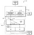
- FIG. 1illustrates a schematic representation of a data storage system, according to one embodiment of the invention.
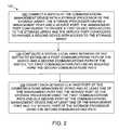
- FIG. 2is a flowchart that illustrates a procedure performed by a communication management device of FIG. 1 , according to one embodiment of the invention.
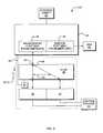
- FIG. 3illustrates a schematic representation of the communication management device of FIG. 1 , according to one embodiment of the invention.
- FIG. 4illustrates a configuration of the communication management device of FIG. 3 when electrically coupled to a storage area network (SAN), according to one embodiment of the invention.
- SANstorage area network
- FIG. 5illustrates a configuration of the communication management device of FIG. 3 when the storage array includes a network attached storage (NAS) device, according to one embodiment of the invention.
- NASnetwork attached storage
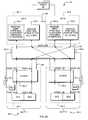
- FIG. 6Aillustrates a configuration of the data storage system having redundant communication management devices.
- FIG. 6Billustrates a configuration of the data storage system of FIG. 6A having switches configured to provide communication between the ports of the redundant communication management devices and the ports of the redundant storage processors of the data storage system, according to one embodiment of the invention.
- Embodiments of the inventionare directed to a method and apparatus for providing a logical separation of a customer device and a service device connected to a data storage system.
- a data storage systemincludes storage array and a switch that is configurable to create numerous network topologies within the system and to maintain separate communications paths between different computerized devices or networks and the storage array.
- a user device and a service devicesuch as a system diagnosis device, can connect to the storage array through the switch.
- the switchcan be logically partitioned into two distinct switches to form two distinct, isolated communications paths between the devices and the storage array. With isolated communications pathways established in the switch, in use, the service device is unable to access the user device coupled to the storage array. As such, the isolated communications pathways limit or prevent the service device from accessing data stored on the user device or from spreading potentially malicious data or files, such as computer viruses to the user device.
- FIG. 1illustrates an arrangement of a data storage system 20 .
- the system 20includes a data storage array 22 (e.g., a configuration of magnetic disk drives) having a storage processor 24 and a communications management device 26 coupled to the storage processor 24 .
- the storage array 22is configured to store and retrieve data for one or more external devices.
- the storage array 22is configured as a storage area network (SAN) that includes a collection of storage arrays 22 that are networked with each other and with a number of computer systems.
- the SANoperates as a server to serve data stored in the storage arrays 22 to end-user computers or systems.
- the storage array 22includes a network attached storage (NAS) device, such as a gateway or a server, which forms a front-end to the storage array 22 .
- NASnetwork attached storage
- the storage processor 24is configured to perform load and store operations on the storage array 22 on behalf of the external devices.
- the storage processor 24is also configured to provide the external devices, such as user devices 31 and service devices 33 , access to the storage array 22 .
- the storage processor 24includes a management port 28 and a service port 30 .
- a user device 31utilizes the management port 28 to load and store data relative to the storage array 22 while a service device 33 utilizes the storage port 30 to diagnose and service the storage array 22 .
- the user device 31can be a stand alone computer device or a data communications device, such as a router or switch, which allows connection of multiple computerized devices to the storage processor 24 .
- the communications management device 26is configured to isolate interaction or communication between the user and service devices 31 , 33 when coupled to the storage array 22 .
- the communications management device 26includes a first port 32 , a second port 34 , and a switch 36 electrically coupled to the first and second ports 32 , 34 .
- each of the ports 32 , 34is configured as an Ethernet port, such as an RJ45 port, to allow connection of a user device or network 31 and a service device or network 33 to the communications management device 26 using a cable, such as a twisted-pair Ethernet cable.
- the switch 36such as a Broadcom 532E 10/100Base-T/TX Ethernet switch is configured to electrically couple the ports 32 , 34 of the device 26 to the ports 28 , 30 of the storage processor 24 through an electrical connection 38 .
- the communications management device 26can include a midplane connector 38 , such as a Metral series connector distributed by FCI (FCI, France), that couples to the storage processor 24 through a midplane 40 .
- the communications management device 26is configured as a field replaceable unit (FRU) that can be electrically coupled to, or decoupled from, the storage array 22 .
- FRUfield replaceable unit
- a software algorithmconfigures a virtual local area networks (VLAN) associated with the switch 36 to create two distinct, isolated communications paths 42 , 44 .
- VLANvirtual local area networks
- the first communications path 42allows communication between a user device 31 coupled to the first port 32 and the management port 28 of the storage processor 24 while the second communications path 44 allows communication between a service device 33 coupled to the second port 32 and the service port 30 of the storage processor 24 .
- the use of separate isolated communications paths 42 , 44minimizes or prevents the device 33 coupled to the second port 34 from accessing the device 31 coupled to the first port 32 and vice versa.
- the switch 36 in this configurationtherefore, provides a level of security to the devices 31 , 33 coupled to the storage array 22 and minimizes the exchange of potentially damaging files, such as computer viruses, between the devices 31 , 33 .
- FIG. 2shows a procedure 100 describing operation of the communications management device 26 .
- the communications management device 26connects the switch 36 of the communications management device 26 with the storage processor 24 of the storage array 22 , the storage processor 24 having the management port 28 and the service port 30 , the management port 28 configured to provide a first device 31 with access to the storage array 22 and the service port 30 configured to provide a second device 33 with access to the storage array 22 .
- the connection between the switch 36 and the storage processorcan be formed as a result of an exchange of network addresses between the communications management device 26 and the storage processor 24 in an autonegotiation procedure.
- the communications management device 26configures a virtual local area network of the switch 36 to establish a first communications path 42 of the switch 36 and a second communications path 44 of the switch 36 , the first communications path 42 being isolated form the second communications path 44 .
- the communications management device 26effectively isolates the first port 32 and the first network 31 from the second port 34 and the second network 33 .
- the communications management device 26establishes the first and second communications paths 42 , 44 on the switch 36 utilizing a software application, as will be described below.
- the switch 36can be configured in hardware, such as by a manufacturer of the switch 36 to establish the first and second communications paths 42 , 44 .
- the communications management device 26conveys data between the first port 32 of the communications management device 26 and at least one of the management port 28 and the service port 30 of the storage processor 24 using the first communications path 42 and between a second port 34 of the communications management device 26 and at least one of the management port 28 and the service port 30 of the storage processor 24 using the second communications path 44 .
- the communications management device 26has configured the VLAN of the switch 36 such that the switch 26 forms the first communications path 42 between the first port 32 and the management port 28 of the storage processor 24 and forms the second communications path 44 between the second port 34 and the service port 30 of the storage processor 24 .
- the communications management device 26can configure the VLAN of the switch 36 in any number of ways.
- the communications management device 26can configure the VLAN of the switch to form a first communications path 42 between the first port 32 and the service port 30 of the storage processor 24 and a second communications path 44 between the second port 34 and the management port 28 of the storage processor 24 .
- the communications management device 26allows the connection of a service device 33 to the storage array 22 to provide diagnosis and service functions while providing a level of security to an attached user device 31 .
- the service device 33is unable to detect the presence of, or access, the user device 31 coupled to the first port 32 through the storage processor 24 .
- the separate communications paths 42 , 44limit or prevent the service device 33 from accessing data stored on the user device 31 and from spreading potentially malicious data or files, such as computer viruses to the user device 31 .
- the VLAN of the switch 36can be configured to create various network topologies within the system 20 in order to maintain separate communications paths between different computerized devices or networks 31 , 33 coupled to the storage array 22 .
- the switch 36can be configured using a number of different mechanisms.
- an external controllersuch as the storage processor 24 is operable to configure the VLAN of the switch 36 .
- the communications management device 26includes a local controller (e.g., disposed on the same circuit board as the switch 36 ) used to configure the VLAN. The local controller provides the communications management device 26 with a level of functionality separate from the functionality storage processor 24 or storage array 22 . Description of the communications management device 26 having such a controller is provided below.
- FIG. 3illustrates an arrangement of the communications management device 26 having a controller 50 electrically coupled to the switch 36 via interface 51 , such as a four-wire serial peripheral interface (SPI).
- the controller 50is operable to perform configuration and diagnostics operations with respect to the switch 36 and to control a set of status indicators 54 , such as light emitting diodes, associated with the communications management device 26 .
- the controller 50is a Cypress Microcontroller model number CY8C27443, distributed by Cypress Semiconductor Corporation.
- the controller 50includes an I2C switch (e.g., isolation module) 52 that allows for electrical communication between the controller 50 and the storage processor 24 over an I2C bus 56 and that isolates the controller 50 from the bus 56 (e.g., in the event that the controller 50 holds ether the data or clock lines low).
- I2C switch 52is a Philips PCA9546 I2C switch, distributed by Philips Semiconductors.
- the controller 50in one arrangement, is operable to configure the VLAN on the switch 36 based upon the requirements of the storage array 22 ( FIG. 1 ). For example, when the controller 50 electrically couples to the storage processor 24 , the controller 50 detects a configuration characteristic 58 of the storage array 22 where the configuration characteristic 58 indicates a particular configuration of the storage array 22 .
- the storage array 22can be configured as a storage area network (SAN) or can be configured to include a network attached storage (NAS) device, such as a gateway or a server, which forms a front-end to the storage array 22 .
- SANstorage area network
- NASnetwork attached storage
- the configuration characteristic 58therefore, allows the controller 50 to detect the “type” of storage array 22 to which it is connected and allows the controller 50 to configure the switch 50 to provide certain communication pathways 42 , 44 between the first and second ports 32 , 34 of the communications management device 26 and the management and service ports 28 , 30 of the storage processor 24 based upon the storage array “type.”
- FIG. 4illustrates an arrangement of the data storage system 20 where the storage array 22 is configured as part of a SAN.
- the controller 50detects a configuration characteristic 58 - 1 indicating that the storage array 22 is configured as part of the SAN. Detection of the configuration characteristic 58 - 1 can occur in a number of ways.
- the controller 50receives the configuration characteristic 58 - 1 as an electric signal from the storage processor 24 via the bus 56 where the signal identifies the SAN configuration of the storage array 22 .
- the controller 50is configured or encoded with the configuration characteristic 58 - 1 as a default. As such, upon electrical coupling to the storage processor 24 , the controller 50 automatically detects the SAN configuration of the storage array 22 .
- the controller 50configures the switch 36 to provide isolated communications paths between the first and second ports 32 , 34 of the communications management device 26 and the management and service ports 28 , 30 of the storage processor 24 , respectively.
- the controller 50configures a VLAN of the switch 26 to establish a first isolated communications path 42 on the switch 36 for communications between the first port 32 and the management port 28 and to establish a second isolated communications path 44 on the switch 36 for communications between the second port 34 and the service port 30 .
- the controller 50isolates the ports 32 , 34 to minimize or prevent interaction or communication between a user device 31 coupled to the first port and a service device 33 coupled to the second port 34 .
- FIG. 5illustrates another arrangement of the data storage system 20 where the storage array 22 is configured to include a NAS device 60 .
- the storage processor 24 and storage array 22are connected between a control station 59 (e.g., a device configured to provide connection of one or more user devices 31 ) and the NAS device 60 in a “daisy chain” configuration.
- a control station 59e.g., a device configured to provide connection of one or more user devices 31
- the NAS device 60in a “daisy chain” configuration.
- one port 28 of the storage processor 24is required to provide the control station 59 with access to the storage array 22 while the other port 30 of the storage processor 24 is required to provide the NAS device 60 with access to the storage array 22 .
- the controller 50detects a configuration characteristic 58 - 2 indicating that the storage array 22 includes a NAS device 60 .
- the controller 50receives the configuration characteristic 58 - 2 , such as an electric signal, from the storage processor 24 via the bus 56 .
- the controller 50configures the switch 50 such that communications from the first and second ports 32 , 34 are directed to the management port 28 on the storage processor 24 .
- the controller 50disables communications between the first and second ports 32 , 34 and the service port 30 , thereby allowing the service port 60 to connect to the NAS device 60 to allow data communication between the NAS device 60 and the storage array 22 .
- the controller 50when the controller 50 configures a VLAN of the switch 50 the controller 50 establishes a first isolated communications path 42 on the switch 36 for communications between the first port 32 of the device 26 and the management port 28 and establishes a second isolated communications path 44 on the switch 36 for communications between the second port 34 of the device 26 and the management port 34 .
- the control station 59can require intercommunication between the first and second ports 32 , 34 .
- the controller 50when the controller 50 establishes the first and second communications paths 42 , 44 on the switch 36 , the controller also establishes a third communications path 45 between the first and second isolated communications paths 42 , 44 to provide communications between the ports 32 , 34 and allow data transfer therebetween.
- the data storage system 20includes a storage array 22 having a single storage processor 24 that is coupled to a single communications management device 26 .
- the data storage system 20includes multiple storage processors and multiple communications management devices to provide failover redundancy in the system 20 .
- the data storage system 20includes first and second storage processors 24 - 1 , 24 - 1 interconnected with first and second communications management devices 26 - 1 , 26 - 2 by the midplane 40 .
- Each of the first and second communications management devices 26 - 1 , 26 - 2are configured as a field replaceable units (FRU) that can be electrically coupled to, or decoupled from, the midplane 40 .
- the communications management devices 26 - 1 , 26 - 2are “hot swappable,”allowing the devices 26 - 1 , 26 - 2 to be decoupled from and recoupled to the midplane 40 during operation of the system 20 without affecting the operability of the system 20 .
- the system 20 shown in FIGS. 6A and 6Bis configured to provide failover redundancy.
- the data storage system 20includes a connection 66 , such as a Common Management Information (CMI) path, between the first and second storage processors 24 - 1 , 24 - 1 .
- CMICommon Management Information
- Such a connection 66allows continued operation of the system 20 in the event of failure of one of the communications management devices 26 - 1 , 26 - 2 . For example, assume the first communications management device 26 - 1 fails.
- a user device 31 or a service device 33 coupled to the second communications management devices 26 - 2can access either of the management ports 28 - 1 , 28 - 2 or the service ports 30 - 1 , 30 - 2 , respectively, through the connection 66 to access the storage array 22 .
- the midplane 40includes multiple locations or slots 80 for coupling of the communications management devices 26 to the storage processors 24 .
- the midplane 40includes a first slot 80 - 1 that provides an electrical connection with the first communications management device 26 - 1 and a second slot 80 - 2 that provides an electrical connection with the second communications management device 26 - 1 .
- the midplane 40is further configured, such as by a hard wiring scheme, to provide data communication between the first port 32 - 1 , 32 - 2 of each device 26 - 1 , 26 - 2 and the first service processor 24 - 1 and between the second port 34 - 1 , 34 - 2 of each device 26 - 1 , 26 - 2 and the second service processor 24 - 1 .
- the midplane 40provides electrical coupling between the first port 32 - 1 of device 26 - 1 and the management port 28 - 1 of the first storage processor 24 - 1 , between the second port 34 - 1 of device 26 - 1 and the service port 30 - 2 of the second storage processor 24 - 2 , between the first port 32 - 2 of device 26 - 2 and the service port 30 - 1 of the first processor 24 - 1 , and between the second port 34 - 2 of the second device 26 - 2 and the management port 28 - 2 of the second storage processor 24 - 2 .
- Such a connection schemeprovides failover redundancy in the system 20 to allow a user device 31 or service device 33 to access the storage array 22 from either of the communications management devices 26 - 1 , 26 - 2 .
- the locations of the first and second ports 32 , 34 on each of the devices 26 - 1 , 26 - 2are “fixed” relative to each other.
- the first port 32is disposed on the communications management device 26 in a fixed location that is above the second port 34 .
- the wiring configuration of the midplane 40effectively “swaps” or reverses the functionality of the ports 34 , 34 . For example, returning to FIG.
- the first or top port 32 - 1when a communications management device 26 is inserted into the first slot 80 - 1 , the first or top port 32 - 1 electrically couples to a management port 28 while the second or bottom port 34 - 1 electrically couples to a service port 30 and when a communications management device 26 is inserted into the second slot 80 - 2 , the first or top port 32 - 2 electrically couples to a service port 30 while the second or bottom port 34 - 2 electrically couples to a management port 30 .
- the communications management device 26is operable to configure the topology of the switch 56 based upon the location or slot 80 into which the communications management device 26 is inserted.
- the system 20provides the communications management device 26 with a coupling characteristic 70 that indicates to the controller 50 the slot or location 50 of the communications management device 26 relative to the midplane 40 .
- the coupling characteristic 70is configured as a bit code signal delivered to the communications management device 26 by the midplane 40 . Based upon the coupling characteristic 70 received, the controller 50 configures the network topology of the switch 36 in a particular arrangement.
- the controller 50 - 1receives a coupling characteristic 70 - 1 , such as the bit code “01”, from the midplane 40 via bus 56 - 1 , which informs the controller 50 as to the location 80 - 1 of the device 26 - 1 .
- a coupling characteristic 70 - 1such as the bit code “01”
- the controller 50configures the VLAN of the switch 36 - 1 to establish a first communications path 42 - 1 between the top port 32 - 1 of the communications management device 26 - 1 and the management port 28 - 1 and to establish a second communications path 44 - 1 between the bottom port 34 - 1 of the communications management device 26 - 1 and the service port 30 - 2 .
- the controller 50 - 2receives a coupling characteristic 70 - 2 , such as the bit code “10”, from the midplane 40 via bus 56 - 2 , which informs the controller 50 - 2 as to the location 80 - 2 of the device 26 - 2 .
- a coupling characteristic 70 - 2such as the bit code “10”
- the controller 50 - 2configures the VLAN of the switch 36 - 2 to establish a first communications path 42 - 2 between the top port 32 - 2 of the communications management device 26 - 2 and the management port 28 - 2 and to establish a second communications path 44 - 2 between the bottom port 34 - 2 of the communications management device 26 - 2 and the service port 30 - 1 .
- a user device 31can always couple to the top port 32 on either communications management device 26 - 1 , 26 - 2 to access the storage array 22 and a service device can always couple to the bottom port 34 on either communications management device 26 - 1 , 26 - 2 to access the storage array 22 .
- the use of the coupling characteristic 70 to configure the switch 70therefore, minimizes or limits potential user confusion when attaching an electronic device (e.g., user device or service device) to the storage array 22 .
- the configuration characteristic 58indicates, to the communications management device 26 , a configuration of the storage array 22 .
- the storage array 22can be configured as a storage area network (SAN) or can be configured to include a network attached storage (NAS) device, such as a gateway or a server, which forms a front-end to the storage array 22 .
- the configuration characteristic 58indicates to the controller 50 the “type” of storage array 22 to which the device 26 is connected, either a SAN or a NAS device. Such description is by way of example only. While the configuration characteristic 58 can indicate connection to a either a SAN or a NAS device, the configuration characteristic 58 can indicate connection of the communications management device 26 to other types of storage arrays as well.
- the data storage systemincludes two storage processors 24 - 1 , 24 - 1 and two communications management devices 26 - 1 , 26 - 1 to provide failover redundancy in the system 20 .
- Such illustrationis by way of example only. In one arrangement, more than two storage processors 24 - 1 , 24 - 1 and two communications management devices 26 - 1 , 26 - 1 can be used to provide failover redundancy.
- each communications management device 26 - 1 , 26 - 2receives connection information 70 - 1 , 70 - 2 from the midplane 40 .
- each communications management device 26 - 1 , 26 - 2receives the connection information from one or both of the storage processors 24 - 1 , 24 - 2 .
- the first communications management device 26 - 1can receive connection information 70 - 1 from the first storage processor 24 - 1 and the second communications management device 26 - 2 can receive connection information 70 - 2 from the second storage processor 24 - 2 .
- the midplane 40is configured (e.g. hard wired) to provide electrical coupling between the ports 32 , 34 of the communications management device 26 and the ports 28 , 30 of the storage processor 24 .
- the midplane 40includes a communications management device connection 68 that allows electrically couples the switches 36 - 1 , 36 - 2 of the communications management devices 26 - 1 , 26 - 2 .
- Such an arrangementallows a service device 33 to access either the first service port 30 - 1 or the second service port 30 - 2 from either of the communications management devices 26 - 1 , 26 - 2 .
- the service device 33can access the first service port 30 - 1 through the first switch 36 - 1 and can access the second service port 30 - 2 through the second switch 36 - 2 via the communications management device connection 68 .
Landscapes
- Engineering & Computer Science (AREA)
- Computer Networks & Wireless Communication (AREA)
- Signal Processing (AREA)
- Computer Security & Cryptography (AREA)
- Computer And Data Communications (AREA)
Abstract
Description
Claims (11)
Priority Applications (2)
| Application Number | Priority Date | Filing Date | Title |
|---|---|---|---|
| US11/394,943US8089903B2 (en) | 2006-03-31 | 2006-03-31 | Method and apparatus for providing a logical separation of a customer device and a service device connected to a data storage system |
| PCT/US2006/045155WO2007114844A1 (en) | 2006-03-31 | 2006-11-21 | Method and apparatus for providing a logical separation of a customer device and a service device connected to a data storage system |
Applications Claiming Priority (1)
| Application Number | Priority Date | Filing Date | Title |
|---|---|---|---|
| US11/394,943US8089903B2 (en) | 2006-03-31 | 2006-03-31 | Method and apparatus for providing a logical separation of a customer device and a service device connected to a data storage system |
Publications (2)
| Publication Number | Publication Date |
|---|---|
| US20070237158A1 US20070237158A1 (en) | 2007-10-11 |
| US8089903B2true US8089903B2 (en) | 2012-01-03 |
Family
ID=37875878
Family Applications (1)
| Application Number | Title | Priority Date | Filing Date |
|---|---|---|---|
| US11/394,943Active2028-02-29US8089903B2 (en) | 2006-03-31 | 2006-03-31 | Method and apparatus for providing a logical separation of a customer device and a service device connected to a data storage system |
Country Status (2)
| Country | Link |
|---|---|
| US (1) | US8089903B2 (en) |
| WO (1) | WO2007114844A1 (en) |
Cited By (1)
| Publication number | Priority date | Publication date | Assignee | Title |
|---|---|---|---|---|
| US20170131921A1 (en)* | 2015-11-10 | 2017-05-11 | Lenovo Enterprise Solutions (Singapore) Pte. Ltd. | Rack mountable computer system that includes microarray storage systems |
Families Citing this family (7)
| Publication number | Priority date | Publication date | Assignee | Title |
|---|---|---|---|---|
| US8208386B2 (en)* | 2007-03-05 | 2012-06-26 | Hewlett-Packard Development Company, L.P. | Discovery of network devices |
| US8909980B1 (en)* | 2012-06-29 | 2014-12-09 | Emc Corporation | Coordinating processing for request redirection |
| US9363315B2 (en)* | 2012-08-28 | 2016-06-07 | Skyera, Llc | Integrated storage and switching for memory systems |
| US9424117B1 (en) | 2013-03-15 | 2016-08-23 | Emc Corporation | Virtual storage processor failover |
| US9537882B2 (en)* | 2014-12-19 | 2017-01-03 | Fedex Corporated Services, Inc. | Methods, systems, and devices for detecting and isolating device posing security threat |
| US9912754B2 (en)* | 2015-05-01 | 2018-03-06 | GM Global Technology Operations LLC | Vehicular data isolation device |
| JP6589505B2 (en)* | 2015-09-24 | 2019-10-16 | ヤマハ株式会社 | Router |
Citations (21)
| Publication number | Priority date | Publication date | Assignee | Title |
|---|---|---|---|---|
| US5283792A (en) | 1990-10-19 | 1994-02-01 | Benchmarq Microelectronics, Inc. | Power up/power down controller and power fail detector for processor |
| US5774640A (en) | 1991-10-21 | 1998-06-30 | Tandem Computers Incorporated | Method and apparatus for providing a fault tolerant network interface controller |
| US5935261A (en) | 1997-06-05 | 1999-08-10 | International Business Machines Corporation | Method and apparatus for detecting handling damage in a disk drive |
| US20030055968A1 (en) | 2001-09-17 | 2003-03-20 | Hochmuth Roland M. | System and method for dynamic configuration of network resources |
| US20030105859A1 (en)* | 2001-08-10 | 2003-06-05 | Garnett Paul J. | Intrusion detection |
| US6633905B1 (en) | 1998-09-22 | 2003-10-14 | Avocent Huntsville Corporation | System and method for accessing and operating personal computers remotely |
| US6651154B1 (en)* | 2000-07-11 | 2003-11-18 | International Business Machines Corporation | Method, system, and program for expanding the storage space in an array of storage units |
| US6678639B2 (en) | 2000-08-04 | 2004-01-13 | Sun Microsystems, Inc. | Automated problem identification system |
| US6681282B1 (en) | 2000-08-31 | 2004-01-20 | Hewlett-Packard Development Company, L.P. | Online control of a multiprocessor computer system |
| US20040028068A1 (en)* | 2002-08-06 | 2004-02-12 | Govind Kizhepat | Dual-mode network storage systems and methods |
| US20040068561A1 (en)* | 2002-10-07 | 2004-04-08 | Hitachi, Ltd. | Method for managing a network including a storage system |
| US6728908B1 (en) | 1999-11-18 | 2004-04-27 | California Institute Of Technology | I2C bus protocol controller with fault tolerance |
| US20050044199A1 (en)* | 2003-08-06 | 2005-02-24 | Kenta Shiga | Storage network management system and method |
| US6873268B2 (en) | 2000-01-21 | 2005-03-29 | Medtronic Minimed, Inc. | Microprocessor controlled ambulatory medical apparatus with hand held communication device |
| US20050114474A1 (en)* | 2003-11-20 | 2005-05-26 | International Business Machines Corporation | Automatic configuration of the network devices via connection to specific switch ports |
| US6910148B1 (en) | 2000-12-07 | 2005-06-21 | Nokia, Inc. | Router and routing protocol redundancy |
| US20050154841A1 (en) | 2001-05-08 | 2005-07-14 | Gautham Sastri | Data storage system for a multi-client network and method of managing such system |
| WO2005076120A1 (en)* | 2004-01-21 | 2005-08-18 | International Business Machines Corporation | Method and apparatus for controlling access to logical units |
| US20050182906A1 (en)* | 2004-02-18 | 2005-08-18 | Paresh Chatterjee | Systems and methods for cache synchronization between redundant storage controllers |
| US20060007491A1 (en) | 2004-07-06 | 2006-01-12 | Hitachi, Ltd. | Setting information holding storage system |
| US7039737B1 (en) | 2003-12-12 | 2006-05-02 | Emc Corporation | Method and apparatus for resource arbitration |
Family Cites Families (1)
| Publication number | Priority date | Publication date | Assignee | Title |
|---|---|---|---|---|
| US528792A (en)* | 1894-11-06 | Cultivator-plow |
- 2006
- 2006-03-31USUS11/394,943patent/US8089903B2/enactiveActive
- 2006-11-21WOPCT/US2006/045155patent/WO2007114844A1/enactiveApplication Filing
Patent Citations (22)
| Publication number | Priority date | Publication date | Assignee | Title |
|---|---|---|---|---|
| US5283792A (en) | 1990-10-19 | 1994-02-01 | Benchmarq Microelectronics, Inc. | Power up/power down controller and power fail detector for processor |
| US5774640A (en) | 1991-10-21 | 1998-06-30 | Tandem Computers Incorporated | Method and apparatus for providing a fault tolerant network interface controller |
| US5935261A (en) | 1997-06-05 | 1999-08-10 | International Business Machines Corporation | Method and apparatus for detecting handling damage in a disk drive |
| US6633905B1 (en) | 1998-09-22 | 2003-10-14 | Avocent Huntsville Corporation | System and method for accessing and operating personal computers remotely |
| US6728908B1 (en) | 1999-11-18 | 2004-04-27 | California Institute Of Technology | I2C bus protocol controller with fault tolerance |
| US6873268B2 (en) | 2000-01-21 | 2005-03-29 | Medtronic Minimed, Inc. | Microprocessor controlled ambulatory medical apparatus with hand held communication device |
| US6651154B1 (en)* | 2000-07-11 | 2003-11-18 | International Business Machines Corporation | Method, system, and program for expanding the storage space in an array of storage units |
| US6678639B2 (en) | 2000-08-04 | 2004-01-13 | Sun Microsystems, Inc. | Automated problem identification system |
| US6681282B1 (en) | 2000-08-31 | 2004-01-20 | Hewlett-Packard Development Company, L.P. | Online control of a multiprocessor computer system |
| US6910148B1 (en) | 2000-12-07 | 2005-06-21 | Nokia, Inc. | Router and routing protocol redundancy |
| US20050154841A1 (en) | 2001-05-08 | 2005-07-14 | Gautham Sastri | Data storage system for a multi-client network and method of managing such system |
| US20030105859A1 (en)* | 2001-08-10 | 2003-06-05 | Garnett Paul J. | Intrusion detection |
| US20030055968A1 (en) | 2001-09-17 | 2003-03-20 | Hochmuth Roland M. | System and method for dynamic configuration of network resources |
| US20040028068A1 (en)* | 2002-08-06 | 2004-02-12 | Govind Kizhepat | Dual-mode network storage systems and methods |
| US20040068561A1 (en)* | 2002-10-07 | 2004-04-08 | Hitachi, Ltd. | Method for managing a network including a storage system |
| US20050044199A1 (en)* | 2003-08-06 | 2005-02-24 | Kenta Shiga | Storage network management system and method |
| US7130900B2 (en)* | 2003-08-06 | 2006-10-31 | Hitachi, Ltd. | Storage network management system and method |
| US20050114474A1 (en)* | 2003-11-20 | 2005-05-26 | International Business Machines Corporation | Automatic configuration of the network devices via connection to specific switch ports |
| US7039737B1 (en) | 2003-12-12 | 2006-05-02 | Emc Corporation | Method and apparatus for resource arbitration |
| WO2005076120A1 (en)* | 2004-01-21 | 2005-08-18 | International Business Machines Corporation | Method and apparatus for controlling access to logical units |
| US20050182906A1 (en)* | 2004-02-18 | 2005-08-18 | Paresh Chatterjee | Systems and methods for cache synchronization between redundant storage controllers |
| US20060007491A1 (en) | 2004-07-06 | 2006-01-12 | Hitachi, Ltd. | Setting information holding storage system |
Non-Patent Citations (8)
| Title |
|---|
| Author Unknown, SunFire B100x and B200x Server Blade Installation and Setup Guide, Sun Microsystems, Mar. 2004, pp. 1 and 7-1 to 7-36.* |
| Author Unknown, Using Proliant Essentials Rapid Deployment Pack for Scripted Blade-Based Switch Configuration, pp. 1-23, Sep. 2003.* |
| D'Antonio, S., et al., "An Architecture for Automatic Configuration of Integrated Networks," Network Operations and Management Symposium, 2004, NOMS 2004, IEEE/IFIP, Seoul, Korea Apr. 19-23, 2004, Piscataway, NJ, USA, 2004, IEEE, vol. 1, Apr. 19, 2004, (pp. 351-364). |
| Data Sheet: EMC CLARiiON CX Series, EMC Corporation, 2004, 8 pages. |
| Hangai, Akira, "Project MegaGrid: Building the Oracle Grid Reference Achitecture,", EMC Corporation,: (online) 2005, as retrieved from the Internet: URL:http://regions.cmg.org/regions/kccmg/Impact2005/ProjectMegaGridTechnical-20050930.ppt, Mar. 28, 2007, (pp. 1-49). |
| http://www.storagesearch.com/fchub.html, "The Shift to NAS Gateways," visited Aug. 17, 2006, 4 pages. |
| The SunFire B100x and B200x Server Blade Installation and Setup Guide (The Guide) (Author Unknown, SunFire B100x and B200x Server Blade Installation and Setup Guide, Sun Microsystems, Mar. 2004, pp. 1 and 7-1 to 7-36.* |
| Written Opinion of the International Searching Authority, mailed Apr. 13, 2007, (8 pages). |
Cited By (2)
| Publication number | Priority date | Publication date | Assignee | Title |
|---|---|---|---|---|
| US20170131921A1 (en)* | 2015-11-10 | 2017-05-11 | Lenovo Enterprise Solutions (Singapore) Pte. Ltd. | Rack mountable computer system that includes microarray storage systems |
| US9870158B2 (en)* | 2015-11-10 | 2018-01-16 | Lenovo Enterprise Solutions (Singapore) Pte. Ltd. | Rack mountable computer system that includes microarray storage systems |
Also Published As
| Publication number | Publication date |
|---|---|
| WO2007114844A1 (en) | 2007-10-11 |
| US20070237158A1 (en) | 2007-10-11 |
Similar Documents
| Publication | Publication Date | Title |
|---|---|---|
| US8089903B2 (en) | Method and apparatus for providing a logical separation of a customer device and a service device connected to a data storage system | |
| US20030130969A1 (en) | Star intelligent platform management bus topology | |
| US6809505B2 (en) | Storage system and method of detecting an improper cable connection in the storage system | |
| US7597582B2 (en) | Backplane for use in a push-in rack for peripherals | |
| US20070234136A1 (en) | Method and apparatus for detecting the presence of errors in data transmitted between components in a data storage system using an I2C protocol | |
| JP2004213651A (en) | Non-interrupted (non-disruptive) power management | |
| US20080155096A1 (en) | Method and Apparatus for Relating Device Name to Physical Location of Device on a Network | |
| US20020156951A1 (en) | Method to validate system configuration | |
| US6675242B2 (en) | Communication bus controller including designation of primary and secondary status according to slot position | |
| US20040162928A1 (en) | High speed multiple ported bus interface reset control system | |
| US8031722B1 (en) | Techniques for controlling a network switch of a data storage system | |
| US20040168008A1 (en) | High speed multiple ported bus interface port state identification system | |
| US20040177198A1 (en) | High speed multiple ported bus interface expander control system | |
| Cisco | Product Overview | |
| US7228338B2 (en) | Multi-service platform module | |
| Cisco | Product Overview | |
| Cisco | Product Overview | |
| Cisco | Product Overview | |
| Cisco | Product Overview | |
| EP1349070A2 (en) | Method of locating a storage device | |
| Cisco | Product Overview | |
| Cisco | Product Overview | |
| Cisco | Product Overview | |
| Cisco | Product Overview | |
| Cisco | Product Overview |
Legal Events
| Date | Code | Title | Description |
|---|---|---|---|
| AS | Assignment | Owner name:EMC CORPORATION, MASSACHUSETTS Free format text:ASSIGNMENT OF ASSIGNORS INTEREST;ASSIGNORS:LEEF, PHILLIP;SULLIVAN, DOUGLAS;FERSON, MATTHEW;REEL/FRAME:017715/0527 Effective date:20060330 | |
| STCF | Information on status: patent grant | Free format text:PATENTED CASE | |
| FPAY | Fee payment | Year of fee payment:4 | |
| AS | Assignment | Owner name:CREDIT SUISSE AG, CAYMAN ISLANDS BRANCH, AS COLLATERAL AGENT, NORTH CAROLINA Free format text:SECURITY AGREEMENT;ASSIGNORS:ASAP SOFTWARE EXPRESS, INC.;AVENTAIL LLC;CREDANT TECHNOLOGIES, INC.;AND OTHERS;REEL/FRAME:040134/0001 Effective date:20160907 Owner name:THE BANK OF NEW YORK MELLON TRUST COMPANY, N.A., AS NOTES COLLATERAL AGENT, TEXAS Free format text:SECURITY AGREEMENT;ASSIGNORS:ASAP SOFTWARE EXPRESS, INC.;AVENTAIL LLC;CREDANT TECHNOLOGIES, INC.;AND OTHERS;REEL/FRAME:040136/0001 Effective date:20160907 Owner name:CREDIT SUISSE AG, CAYMAN ISLANDS BRANCH, AS COLLAT Free format text:SECURITY AGREEMENT;ASSIGNORS:ASAP SOFTWARE EXPRESS, INC.;AVENTAIL LLC;CREDANT TECHNOLOGIES, INC.;AND OTHERS;REEL/FRAME:040134/0001 Effective date:20160907 Owner name:THE BANK OF NEW YORK MELLON TRUST COMPANY, N.A., A Free format text:SECURITY AGREEMENT;ASSIGNORS:ASAP SOFTWARE EXPRESS, INC.;AVENTAIL LLC;CREDANT TECHNOLOGIES, INC.;AND OTHERS;REEL/FRAME:040136/0001 Effective date:20160907 | |
| AS | Assignment | Owner name:EMC IP HOLDING COMPANY LLC, MASSACHUSETTS Free format text:ASSIGNMENT OF ASSIGNORS INTEREST;ASSIGNOR:EMC CORPORATION;REEL/FRAME:040203/0001 Effective date:20160906 | |
| AS | Assignment | Owner name:THE BANK OF NEW YORK MELLON TRUST COMPANY, N.A., T Free format text:SECURITY AGREEMENT;ASSIGNORS:CREDANT TECHNOLOGIES, INC.;DELL INTERNATIONAL L.L.C.;DELL MARKETING L.P.;AND OTHERS;REEL/FRAME:049452/0223 Effective date:20190320 Owner name:THE BANK OF NEW YORK MELLON TRUST COMPANY, N.A., TEXAS Free format text:SECURITY AGREEMENT;ASSIGNORS:CREDANT TECHNOLOGIES, INC.;DELL INTERNATIONAL L.L.C.;DELL MARKETING L.P.;AND OTHERS;REEL/FRAME:049452/0223 Effective date:20190320 | |
| MAFP | Maintenance fee payment | Free format text:PAYMENT OF MAINTENANCE FEE, 8TH YEAR, LARGE ENTITY (ORIGINAL EVENT CODE: M1552); ENTITY STATUS OF PATENT OWNER: LARGE ENTITY Year of fee payment:8 | |
| AS | Assignment | Owner name:THE BANK OF NEW YORK MELLON TRUST COMPANY, N.A., TEXAS Free format text:SECURITY AGREEMENT;ASSIGNORS:CREDANT TECHNOLOGIES INC.;DELL INTERNATIONAL L.L.C.;DELL MARKETING L.P.;AND OTHERS;REEL/FRAME:053546/0001 Effective date:20200409 | |
| AS | Assignment | Owner name:WYSE TECHNOLOGY L.L.C., CALIFORNIA Free format text:RELEASE BY SECURED PARTY;ASSIGNOR:CREDIT SUISSE AG, CAYMAN ISLANDS BRANCH;REEL/FRAME:058216/0001 Effective date:20211101 Owner name:SCALEIO LLC, MASSACHUSETTS Free format text:RELEASE BY SECURED PARTY;ASSIGNOR:CREDIT SUISSE AG, CAYMAN ISLANDS BRANCH;REEL/FRAME:058216/0001 Effective date:20211101 Owner name:MOZY, INC., WASHINGTON Free format text:RELEASE BY SECURED PARTY;ASSIGNOR:CREDIT SUISSE AG, CAYMAN ISLANDS BRANCH;REEL/FRAME:058216/0001 Effective date:20211101 Owner name:MAGINATICS LLC, CALIFORNIA Free format text:RELEASE BY SECURED PARTY;ASSIGNOR:CREDIT SUISSE AG, CAYMAN ISLANDS BRANCH;REEL/FRAME:058216/0001 Effective date:20211101 Owner name:FORCE10 NETWORKS, INC., CALIFORNIA Free format text:RELEASE BY SECURED PARTY;ASSIGNOR:CREDIT SUISSE AG, CAYMAN ISLANDS BRANCH;REEL/FRAME:058216/0001 Effective date:20211101 Owner name:EMC IP HOLDING COMPANY LLC, TEXAS Free format text:RELEASE BY SECURED PARTY;ASSIGNOR:CREDIT SUISSE AG, CAYMAN ISLANDS BRANCH;REEL/FRAME:058216/0001 Effective date:20211101 Owner name:EMC CORPORATION, MASSACHUSETTS Free format text:RELEASE BY SECURED PARTY;ASSIGNOR:CREDIT SUISSE AG, CAYMAN ISLANDS BRANCH;REEL/FRAME:058216/0001 Effective date:20211101 Owner name:DELL SYSTEMS CORPORATION, TEXAS Free format text:RELEASE BY SECURED PARTY;ASSIGNOR:CREDIT SUISSE AG, CAYMAN ISLANDS BRANCH;REEL/FRAME:058216/0001 Effective date:20211101 Owner name:DELL SOFTWARE INC., CALIFORNIA Free format text:RELEASE BY SECURED PARTY;ASSIGNOR:CREDIT SUISSE AG, CAYMAN ISLANDS BRANCH;REEL/FRAME:058216/0001 Effective date:20211101 Owner name:DELL PRODUCTS L.P., TEXAS Free format text:RELEASE BY SECURED PARTY;ASSIGNOR:CREDIT SUISSE AG, CAYMAN ISLANDS BRANCH;REEL/FRAME:058216/0001 Effective date:20211101 Owner name:DELL MARKETING L.P., TEXAS Free format text:RELEASE BY SECURED PARTY;ASSIGNOR:CREDIT SUISSE AG, CAYMAN ISLANDS BRANCH;REEL/FRAME:058216/0001 Effective date:20211101 Owner name:DELL INTERNATIONAL, L.L.C., TEXAS Free format text:RELEASE BY SECURED PARTY;ASSIGNOR:CREDIT SUISSE AG, CAYMAN ISLANDS BRANCH;REEL/FRAME:058216/0001 Effective date:20211101 Owner name:DELL USA L.P., TEXAS Free format text:RELEASE BY SECURED PARTY;ASSIGNOR:CREDIT SUISSE AG, CAYMAN ISLANDS BRANCH;REEL/FRAME:058216/0001 Effective date:20211101 Owner name:CREDANT TECHNOLOGIES, INC., TEXAS Free format text:RELEASE BY SECURED PARTY;ASSIGNOR:CREDIT SUISSE AG, CAYMAN ISLANDS BRANCH;REEL/FRAME:058216/0001 Effective date:20211101 Owner name:AVENTAIL LLC, CALIFORNIA Free format text:RELEASE BY SECURED PARTY;ASSIGNOR:CREDIT SUISSE AG, CAYMAN ISLANDS BRANCH;REEL/FRAME:058216/0001 Effective date:20211101 Owner name:ASAP SOFTWARE EXPRESS, INC., ILLINOIS Free format text:RELEASE BY SECURED PARTY;ASSIGNOR:CREDIT SUISSE AG, CAYMAN ISLANDS BRANCH;REEL/FRAME:058216/0001 Effective date:20211101 | |
| AS | Assignment | Owner name:SCALEIO LLC, MASSACHUSETTS Free format text:RELEASE OF SECURITY INTEREST IN PATENTS PREVIOUSLY RECORDED AT REEL/FRAME (040136/0001);ASSIGNOR:THE BANK OF NEW YORK MELLON TRUST COMPANY, N.A., AS NOTES COLLATERAL AGENT;REEL/FRAME:061324/0001 Effective date:20220329 Owner name:EMC IP HOLDING COMPANY LLC (ON BEHALF OF ITSELF AND AS SUCCESSOR-IN-INTEREST TO MOZY, INC.), TEXAS Free format text:RELEASE OF SECURITY INTEREST IN PATENTS PREVIOUSLY RECORDED AT REEL/FRAME (040136/0001);ASSIGNOR:THE BANK OF NEW YORK MELLON TRUST COMPANY, N.A., AS NOTES COLLATERAL AGENT;REEL/FRAME:061324/0001 Effective date:20220329 Owner name:EMC CORPORATION (ON BEHALF OF ITSELF AND AS SUCCESSOR-IN-INTEREST TO MAGINATICS LLC), MASSACHUSETTS Free format text:RELEASE OF SECURITY INTEREST IN PATENTS PREVIOUSLY RECORDED AT REEL/FRAME (040136/0001);ASSIGNOR:THE BANK OF NEW YORK MELLON TRUST COMPANY, N.A., AS NOTES COLLATERAL AGENT;REEL/FRAME:061324/0001 Effective date:20220329 Owner name:DELL MARKETING CORPORATION (SUCCESSOR-IN-INTEREST TO FORCE10 NETWORKS, INC. AND WYSE TECHNOLOGY L.L.C.), TEXAS Free format text:RELEASE OF SECURITY INTEREST IN PATENTS PREVIOUSLY RECORDED AT REEL/FRAME (040136/0001);ASSIGNOR:THE BANK OF NEW YORK MELLON TRUST COMPANY, N.A., AS NOTES COLLATERAL AGENT;REEL/FRAME:061324/0001 Effective date:20220329 Owner name:DELL PRODUCTS L.P., TEXAS Free format text:RELEASE OF SECURITY INTEREST IN PATENTS PREVIOUSLY RECORDED AT REEL/FRAME (040136/0001);ASSIGNOR:THE BANK OF NEW YORK MELLON TRUST COMPANY, N.A., AS NOTES COLLATERAL AGENT;REEL/FRAME:061324/0001 Effective date:20220329 Owner name:DELL INTERNATIONAL L.L.C., TEXAS Free format text:RELEASE OF SECURITY INTEREST IN PATENTS PREVIOUSLY RECORDED AT REEL/FRAME (040136/0001);ASSIGNOR:THE BANK OF NEW YORK MELLON TRUST COMPANY, N.A., AS NOTES COLLATERAL AGENT;REEL/FRAME:061324/0001 Effective date:20220329 Owner name:DELL USA L.P., TEXAS Free format text:RELEASE OF SECURITY INTEREST IN PATENTS PREVIOUSLY RECORDED AT REEL/FRAME (040136/0001);ASSIGNOR:THE BANK OF NEW YORK MELLON TRUST COMPANY, N.A., AS NOTES COLLATERAL AGENT;REEL/FRAME:061324/0001 Effective date:20220329 Owner name:DELL MARKETING L.P. (ON BEHALF OF ITSELF AND AS SUCCESSOR-IN-INTEREST TO CREDANT TECHNOLOGIES, INC.), TEXAS Free format text:RELEASE OF SECURITY INTEREST IN PATENTS PREVIOUSLY RECORDED AT REEL/FRAME (040136/0001);ASSIGNOR:THE BANK OF NEW YORK MELLON TRUST COMPANY, N.A., AS NOTES COLLATERAL AGENT;REEL/FRAME:061324/0001 Effective date:20220329 Owner name:DELL MARKETING CORPORATION (SUCCESSOR-IN-INTEREST TO ASAP SOFTWARE EXPRESS, INC.), TEXAS Free format text:RELEASE OF SECURITY INTEREST IN PATENTS PREVIOUSLY RECORDED AT REEL/FRAME (040136/0001);ASSIGNOR:THE BANK OF NEW YORK MELLON TRUST COMPANY, N.A., AS NOTES COLLATERAL AGENT;REEL/FRAME:061324/0001 Effective date:20220329 | |
| AS | Assignment | Owner name:SCALEIO LLC, MASSACHUSETTS Free format text:RELEASE OF SECURITY INTEREST IN PATENTS PREVIOUSLY RECORDED AT REEL/FRAME (045455/0001);ASSIGNOR:THE BANK OF NEW YORK MELLON TRUST COMPANY, N.A., AS NOTES COLLATERAL AGENT;REEL/FRAME:061753/0001 Effective date:20220329 Owner name:EMC IP HOLDING COMPANY LLC (ON BEHALF OF ITSELF AND AS SUCCESSOR-IN-INTEREST TO MOZY, INC.), TEXAS Free format text:RELEASE OF SECURITY INTEREST IN PATENTS PREVIOUSLY RECORDED AT REEL/FRAME (045455/0001);ASSIGNOR:THE BANK OF NEW YORK MELLON TRUST COMPANY, N.A., AS NOTES COLLATERAL AGENT;REEL/FRAME:061753/0001 Effective date:20220329 Owner name:EMC CORPORATION (ON BEHALF OF ITSELF AND AS SUCCESSOR-IN-INTEREST TO MAGINATICS LLC), MASSACHUSETTS Free format text:RELEASE OF SECURITY INTEREST IN PATENTS PREVIOUSLY RECORDED AT REEL/FRAME (045455/0001);ASSIGNOR:THE BANK OF NEW YORK MELLON TRUST COMPANY, N.A., AS NOTES COLLATERAL AGENT;REEL/FRAME:061753/0001 Effective date:20220329 Owner name:DELL MARKETING CORPORATION (SUCCESSOR-IN-INTEREST TO FORCE10 NETWORKS, INC. AND WYSE TECHNOLOGY L.L.C.), TEXAS Free format text:RELEASE OF SECURITY INTEREST IN PATENTS PREVIOUSLY RECORDED AT REEL/FRAME (045455/0001);ASSIGNOR:THE BANK OF NEW YORK MELLON TRUST COMPANY, N.A., AS NOTES COLLATERAL AGENT;REEL/FRAME:061753/0001 Effective date:20220329 Owner name:DELL PRODUCTS L.P., TEXAS Free format text:RELEASE OF SECURITY INTEREST IN PATENTS PREVIOUSLY RECORDED AT REEL/FRAME (045455/0001);ASSIGNOR:THE BANK OF NEW YORK MELLON TRUST COMPANY, N.A., AS NOTES COLLATERAL AGENT;REEL/FRAME:061753/0001 Effective date:20220329 Owner name:DELL INTERNATIONAL L.L.C., TEXAS Free format text:RELEASE OF SECURITY INTEREST IN PATENTS PREVIOUSLY RECORDED AT REEL/FRAME (045455/0001);ASSIGNOR:THE BANK OF NEW YORK MELLON TRUST COMPANY, N.A., AS NOTES COLLATERAL AGENT;REEL/FRAME:061753/0001 Effective date:20220329 Owner name:DELL USA L.P., TEXAS Free format text:RELEASE OF SECURITY INTEREST IN PATENTS PREVIOUSLY RECORDED AT REEL/FRAME (045455/0001);ASSIGNOR:THE BANK OF NEW YORK MELLON TRUST COMPANY, N.A., AS NOTES COLLATERAL AGENT;REEL/FRAME:061753/0001 Effective date:20220329 Owner name:DELL MARKETING L.P. (ON BEHALF OF ITSELF AND AS SUCCESSOR-IN-INTEREST TO CREDANT TECHNOLOGIES, INC.), TEXAS Free format text:RELEASE OF SECURITY INTEREST IN PATENTS PREVIOUSLY RECORDED AT REEL/FRAME (045455/0001);ASSIGNOR:THE BANK OF NEW YORK MELLON TRUST COMPANY, N.A., AS NOTES COLLATERAL AGENT;REEL/FRAME:061753/0001 Effective date:20220329 Owner name:DELL MARKETING CORPORATION (SUCCESSOR-IN-INTEREST TO ASAP SOFTWARE EXPRESS, INC.), TEXAS Free format text:RELEASE OF SECURITY INTEREST IN PATENTS PREVIOUSLY RECORDED AT REEL/FRAME (045455/0001);ASSIGNOR:THE BANK OF NEW YORK MELLON TRUST COMPANY, N.A., AS NOTES COLLATERAL AGENT;REEL/FRAME:061753/0001 Effective date:20220329 | |
| AS | Assignment | Owner name:DELL MARKETING L.P. (ON BEHALF OF ITSELF AND AS SUCCESSOR-IN-INTEREST TO CREDANT TECHNOLOGIES, INC.), TEXAS Free format text:RELEASE OF SECURITY INTEREST IN PATENTS PREVIOUSLY RECORDED AT REEL/FRAME (053546/0001);ASSIGNOR:THE BANK OF NEW YORK MELLON TRUST COMPANY, N.A., AS NOTES COLLATERAL AGENT;REEL/FRAME:071642/0001 Effective date:20220329 Owner name:DELL INTERNATIONAL L.L.C., TEXAS Free format text:RELEASE OF SECURITY INTEREST IN PATENTS PREVIOUSLY RECORDED AT REEL/FRAME (053546/0001);ASSIGNOR:THE BANK OF NEW YORK MELLON TRUST COMPANY, N.A., AS NOTES COLLATERAL AGENT;REEL/FRAME:071642/0001 Effective date:20220329 Owner name:DELL PRODUCTS L.P., TEXAS Free format text:RELEASE OF SECURITY INTEREST IN PATENTS PREVIOUSLY RECORDED AT REEL/FRAME (053546/0001);ASSIGNOR:THE BANK OF NEW YORK MELLON TRUST COMPANY, N.A., AS NOTES COLLATERAL AGENT;REEL/FRAME:071642/0001 Effective date:20220329 Owner name:DELL USA L.P., TEXAS Free format text:RELEASE OF SECURITY INTEREST IN PATENTS PREVIOUSLY RECORDED AT REEL/FRAME (053546/0001);ASSIGNOR:THE BANK OF NEW YORK MELLON TRUST COMPANY, N.A., AS NOTES COLLATERAL AGENT;REEL/FRAME:071642/0001 Effective date:20220329 Owner name:EMC CORPORATION, MASSACHUSETTS Free format text:RELEASE OF SECURITY INTEREST IN PATENTS PREVIOUSLY RECORDED AT REEL/FRAME (053546/0001);ASSIGNOR:THE BANK OF NEW YORK MELLON TRUST COMPANY, N.A., AS NOTES COLLATERAL AGENT;REEL/FRAME:071642/0001 Effective date:20220329 Owner name:DELL MARKETING CORPORATION (SUCCESSOR-IN-INTEREST TO FORCE10 NETWORKS, INC. AND WYSE TECHNOLOGY L.L.C.), TEXAS Free format text:RELEASE OF SECURITY INTEREST IN PATENTS PREVIOUSLY RECORDED AT REEL/FRAME (053546/0001);ASSIGNOR:THE BANK OF NEW YORK MELLON TRUST COMPANY, N.A., AS NOTES COLLATERAL AGENT;REEL/FRAME:071642/0001 Effective date:20220329 Owner name:EMC IP HOLDING COMPANY LLC, TEXAS Free format text:RELEASE OF SECURITY INTEREST IN PATENTS PREVIOUSLY RECORDED AT REEL/FRAME (053546/0001);ASSIGNOR:THE BANK OF NEW YORK MELLON TRUST COMPANY, N.A., AS NOTES COLLATERAL AGENT;REEL/FRAME:071642/0001 Effective date:20220329 | |
| MAFP | Maintenance fee payment | Free format text:PAYMENT OF MAINTENANCE FEE, 12TH YEAR, LARGE ENTITY (ORIGINAL EVENT CODE: M1553); ENTITY STATUS OF PATENT OWNER: LARGE ENTITY Year of fee payment:12 |