US8089515B2 - Method and device for controlling auto focusing of a video camera by tracking a region-of-interest - Google Patents
Method and device for controlling auto focusing of a video camera by tracking a region-of-interestDownload PDFInfo
- Publication number
- US8089515B2 US8089515B2US12/087,207US8720709AUS8089515B2US 8089515 B2US8089515 B2US 8089515B2US 8720709 AUS8720709 AUS 8720709AUS 8089515 B2US8089515 B2US 8089515B2
- Authority
- US
- United States
- Prior art keywords
- roi
- region
- image frame
- tracking
- order
- Prior art date
- Legal status (The legal status is an assumption and is not a legal conclusion. Google has not performed a legal analysis and makes no representation as to the accuracy of the status listed.)
- Active, expires
Links
Images


Classifications
- G—PHYSICS
- G06—COMPUTING OR CALCULATING; COUNTING
- G06T—IMAGE DATA PROCESSING OR GENERATION, IN GENERAL
- G06T7/00—Image analysis
- G06T7/20—Analysis of motion
- G—PHYSICS
- G03—PHOTOGRAPHY; CINEMATOGRAPHY; ANALOGOUS TECHNIQUES USING WAVES OTHER THAN OPTICAL WAVES; ELECTROGRAPHY; HOLOGRAPHY
- G03B—APPARATUS OR ARRANGEMENTS FOR TAKING PHOTOGRAPHS OR FOR PROJECTING OR VIEWING THEM; APPARATUS OR ARRANGEMENTS EMPLOYING ANALOGOUS TECHNIQUES USING WAVES OTHER THAN OPTICAL WAVES; ACCESSORIES THEREFOR
- G03B13/00—Viewfinders; Focusing aids for cameras; Means for focusing for cameras; Autofocus systems for cameras
- G03B13/32—Means for focusing
- G03B13/34—Power focusing
- G03B13/36—Autofocus systems
- H—ELECTRICITY
- H04—ELECTRIC COMMUNICATION TECHNIQUE
- H04N—PICTORIAL COMMUNICATION, e.g. TELEVISION
- H04N23/00—Cameras or camera modules comprising electronic image sensors; Control thereof
- H04N23/60—Control of cameras or camera modules
- H04N23/67—Focus control based on electronic image sensor signals
- H04N23/673—Focus control based on electronic image sensor signals based on contrast or high frequency components of image signals, e.g. hill climbing method
Definitions
- the present inventionrelates to an electronic device equipped with a video imaging process capability, which device includes
- the inventionalso relates to a method and a corresponding program product.
- FIG. 1 ahas been presented a prior art example of the generic architecture of a passive auto-focus system arranged in connection with a digital imaging system 10 ′.
- auto-focus 12is the procedure of moving of the lens 14 in and out until the sharpest possible image I of the subject T is obtained.
- the lens 14has to be at a certain distance from an image sensor 11 to form a clear image I.
- the image sensor 11 of the device 10 ′produces (image) data I for the auto-focus unit 12 .
- Auto-focus unit 12calculates parameters for motor 13 adjusting the position of the lens 14 on the basis of the data.
- the motor 13adjusts the lens 14 owing to which the captured image I is more accurate.
- AAFactive auto-focus
- PAFpassive auto-focus
- the cameraemits a signal to the direction of the object (or scene) to capture in order to detect the distance of the subject.
- the signalcould be a sound wave, as it is the case in submarines under water, or an infrared wave.
- the time of the reflected waveis then used to calculate distance. Basically, this is similar to the Doppler radar principle. Based on the distance the auto-focus unit then tells the focus motor which way to move the lens and how far to move it.
- the camerasdetermine the distance to the subject by analyzing the image.
- the imageis first captured, and through a sensor, dedicated for the auto-focus, it is analyzed.
- the sensor specific for the auto-focus usehas a limited number of pixels. Thus, a portion of the image, only, is often utilized.
- a typical auto-focus sensor applied in PAFis a charge-coupled device (CCD). It provides input to algorithms that compute the contrast of the actual picture elements.
- the CCDis typically a single strip of 100 or 200 pixels, for example. Light from the scene hits this strip and the microprocessor looks at the values from each pixel. This data is then analyzed by checking the sharpness, horizontally or vertically, and/or its contrast. The obtained results are then sent as a feedback to the lens, which is adjusted to improve the sharpness and the contrast. So, for example, if the image is very blurred then it is understood that the lens needs to move forward in order to adjust the focus.
- ROI tracking process initializationIn the literature, different techniques were used for object identification and ROI tracking process initialization. Such a problem arises in many applications such as the initialization of region of interest (ROI) tracking in a video sequence.
- ROIregion of interest
- the skin color informationis used to detect the foreground.
- Some approachesapply feature-based refinement to distinguish faces from other parts of the body with similar color characteristics, e.g. hands.
- Such methodscannot be applicable in the general case where the target can be of any type, such as, for example, a car, an airplane, an athlete, an animal, etc.
- the targetis not necessarily of a particular type, e.g. human face, but can rather be any object, the identification can not be done automatically and user input becomes imminent.
- a tracking processis performed in order to localize the ROI in each frame.
- visual tracking of non-rigid objects in a video sequencecan be seen as a recursive-matching problem from which certain reliability is required.
- a region in the current frameis matched to a previous instance, or a model, of the target.
- the difficulty of the tracking problemis of multiple dimensions.
- 3D objects captured on a 2D video framedo not capture the depth of the objects. Changes in the object that occur with time, such as translation, rotation, deformation, etc., are not captured faithfully on the 2D screen. Tracking the object while it undergoes these changes is a challenging task.
- the objectmay also be affected by its surroundings and other external factors. Some examples of these are interference with other objects, occlusions, changes in background and lighting conditions, capturing conditions, camera motion, etc. All these numerous factors impede a robust and reliable tracking mechanism of the object-of-interest.
- the matchingcan be done based on the colour, shape or other features. Methods based on one of these aspects usually provide robustness in one sense but show weaknesses under some other scenarios. Finally, the tracking of shapes and features involves significant computational load. Therefore, algorithms that consider more than one multiple visual aspect of the target can enhance tracking performance but at the expense of higher computational load.
- the present inventionis intended to create a new type of electronic device equipped with video imaging process capability and auto-focus means, as well as an auto-focus method for video imaging.
- the characteristic features of the electronic device according to the inventionare stated in the accompanying Claim 1 while the characteristic features of the method applied in it are stated in Claim 17 .
- the inventionalso relates to a program product, the characteristic features of which are stated in the accompanying Claim 33 .
- the inventiondescribes algorithms to utilize in the auto-focus modules in cameras to improve video capturing.
- the approachesare based on utilizing a region of interest tracking technique to identify the optimal parameters for focus control.
- the inventionprovides means for efficiently keeping the focus on an object during video recording process.
- the inventionis composed of an algorithm for identifying an object, tracking it and an auto-focus unit which uses the tracking results to control the lens system.
- the inventionoptimizes the performance of the passive auto-focus lens by introducing a region of interest tracking technique, which makes the object of interest sharp and with the same size in proportion to the video frames along the video sequence.
- the techniquecan be implemented, for example, within an auto-focus unit. With the ROI tracking results a more accurate update on the lens movements is reached, while the camera is recording the auto-focus is done automatically.
- the region-of-interest (ROI) tracking in a video sequenceis performed applying macroblock-based region-of-interest tracking method.
- two histogramsmay be calculated in order to find out which pixels of the current macroblock of the current image frame are target pixels and which pixels are background pixels.
- the histogramsare calculated for the ROI region and for the background region of the previous frame.
- the information which regions belong to the ROI and which regions belong to backgroundhave been achieved from the ROI mask of the previous frame.
- the inventiondescribes a new approach characterized by tracking robustness and low computational complexity. These two features are the main measures of whether or not a tracking technique is implementable in an application targeting mobile devices where system resources are very limited.
- the tracking scheme according to the inventionprovides robustness to shape deformation, partial occlusion and environment variations while maintaining a low computational complexity with reliable and efficient performance.
- the inventionit is also possible to apply a semi-automatic identification of an object or a region of interest (ROI) in an image or a video frame.
- ROIregion of interest
- the local color-content inside and around the defined area including the object of interestis analyzed in order to distinguish between background and target.
- the output of this processmay be a mask describing the ROI.
- the developed algorithmis quite simple.
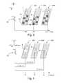
- FIG. 1 ashows a principle of a generic architecture of a passive auto-focus system according to the prior art
- FIG. 1 bshows a principle of a device according to the invention in which the identification and the tracking of the ROI is applied in connection with the determination of the spatial position of the ROI
- FIG. 2shows an example of the method according to the invention as a flowchart
- FIG. 3shows an illustration of the ROI tracking in the scene plane
- FIG. 4shows an illustration of the ROI tracking in the Z-plane
- FIG. 5shows an example of the ROI identification process according to the invention as a flowchart
- FIGS. 6 a and 6 bshow examples of the window selection procedure in order to define the area including the object of interest
- FIG. 7 ashows an example of the color-content based distinction of target from background using the color histograms corresponding to exocentric rectangular regions
- FIG. 7 bshows an example of the color histograms of the exocentric rectangular regions
- FIGS. 8 a and 8 bshow examples of the produced ROI masks of embodiments of FIGS. 6 a and 6 b
- FIG. 9shows an example of the ROI tracking process according to the invention as a flowchart
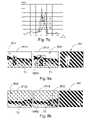
- FIGS. 10 a , 10 bshow principle examples of the generation of the block-wise histograms, for the background and the ROI,
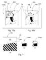
- FIG. 11show examples of the shape of the mask block and probability macroblocks in connection with the shape matching procedure
- FIGS. 12 a , 12 bshow a mask of the Y-component and the ROI mask as an example in the real imaging situation
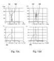
- FIGS. 13 a - 13 fshow examples of the color componentwise and probability histograms from the real imaging situation presented in FIGS. 12 a and 12 b.
- electronic devices 10include camera means 11 .
- examples of such devicesinclude mobile stations, PDA (Personal Digital Assistant) devices, and similar ‘smart communicators’ and also surveillance cameras.
- the concept ‘electronic device’can be understood very widely.
- itcan be a device, which is equipped, or which can be equipped with a digital video imaging capability.
- the inventionis described in connection with a mobile station 10 , by way of example.
- FIG. 1 bshows a rough schematic example of the functionalities in a device 10 , in as much as they relate to the invention.
- the camera means of the device 10can include the functional components or sub-modules 11 - 14 , which are, as such known, shown in FIG. 1 b and already described in connection with FIG. 1 a in the prior art section.
- These modules 11 - 14form a loop architecture, which is performed continuously in connection with the video recording.
- the video recordingmay be understood as well as the measures that are performed before the actual recording process (initialization measures) and also during the actual recording in which storing or network streaming of the video data is performed.
- At least part of the functionalities of the cameramay be performed by using data-processing means, i.e. CPU 15 - 17 .
- Thismay include one or more processor units or corresponding.
- the image processor CPUmay be mentioned with the auto-focus unit 12 included in that.
- the auto-focus unit 12may also be a separate entity which communicates with main processor CPU.
- the program product 30is implemented on either the HW or SW level, in order to perform actions according to the invention.
- the device 10can also include a display/viewfinder 18 on which information can be visualized to the user of the device 10 .
- the device 10also includes a processor functionality CPU, which includes functionalities for controlling the various operations of the device 10 .
- the actions relating to the auto-focusing process according to the inventioncan be performed using program 30 .
- the program 30 , or the code 31 forming itcan be written on a storage medium MEM in the device 10 , for example, on an updatable, non-volatile semiconductor memory, or, on the other hand, it can also be burned directly in a circuit CPU, 15 - 17 as an HW implementation.
- the code 31consists of a group of commands 31 . 1 - 31 . 18 to be performed in a set sequence, by means of which data processing according to a selected processing algorithm is achieved. In this case, data processing can be mainly understood actions and measures relating to ROI identification 15 that is performed before storing video recording process.
- Data processing meansalso in this connection the measures and actions performed by the ROI tracking 16 , determination process 17 of the spatial position of the ROI in the video frame and also an auto-focusing process 12 . These three actions are all performed during the actual video recording process, as will be explained in later in greater detail.
- FIG. 2presents as a flowchart an example of the main stages of the invention.
- the basic idea of the inventionis not intended to be limited to these steps or their performance order.
- other additional stepsmay also become into the question and/or the performance order of the presented (or currently not presented) steps may also vary, if that is possible.
- Theremay also be sub-processes, like the ROI tracking 204 that is performed independently relative to the other steps (code means 31 . 2 , 31 . 7 ). Owing to this the ROI tracking 204 , 16 provides always the most refresh ROI mask for the unit 17 that determines the spatial position of the ROI in a frame and which provides that coordinate information for the auto-focus unit 12 .
- the method according to the inventionmay be built on top of a passive auto-focus method if the invention is applied in connection with the video capturing process.
- the methodis basically divided into stages (tracking and updating the lens, or in general, optics 14 ).
- an object of interestis first identified. This identification may be performed either by the user aided or totally automatically by the device 10 .
- the region of interestis a target defined by a user or an application in a frame in a video sequence.
- the object Tis made the interest of the camera lens 14 and the focus is operated to get the sharpest image quality of this object.
- the region-of-interest (ROI) tracking algorithm 16is following it and sending feedback parameters to the auto-focus actuator (motor) 13 to move the auto-focus lens 14 accordingly backward or forward depending on the current situation.
- stage 202may be performed where the region-of-interest is identified in the viewfinder video (code means 31 . 1 ).
- This proceduremay include several sub-stages which are described in more details in connection with FIG. 5 which is explained more precisely hereinafter. Of course, other methods may also be applied in this ROI identification process. The invention is not intended to limit this to the embodiment presented in FIG. 5 .
- the video capturing processstarts in order to produce video for the desired purpose (for example, for storing to the memory MEM or for streaming to the network) (stage 203 ).
- the captured video image datai.e. the video frames, are processed at stage 203 ′ as a manner known as such after which they are stored to the memory MEM of the device 10 , for example.
- auto-focusis also performed in the loop 204 - 213 in order to adjust the focus lens system 14 and keep the target in the image as sharp as possible.
- a first stage 204 in this loop tracking of the ROIis performed in the current video frame by the ROI tracking unit 16 .
- This ROI tracking stage 204also includes several sub-stages which are also described as an embodiment more precisely in a little bit later. Basically any method may be used in this connection.
- Owing to the ROI tracking stage 204 achieved data/resultsmay be used in the next stage 205 that is the determination of the plane position of the ROI (code means 31 . 3 , 31 . 4 ).
- FIG. 3an example of the determination of the plane position of the ROI has been presented.
- the frame FR 1only exists on this current loop cycle.
- There the head Tis the ROI, i.e. the target, and its spatial position in the X-Y plane may vary between the frames FR 1 -FR 3 during the recording process.
- this stage 205the XY-coordinates of the ROI's new position in the image frame FR 1 -FR 3 are found. This information is then applied in connection with the auto-focus stage 210 .
- FIG. 4presents an example relating to that.
- the middle frame FR 2 ′presents the size of the target T at initial capturing point.
- the framesmay be achieved, for example, from the stage 202 , or from each loop cycle if the shape of the ROI changes during recording process.
- the ROI_ratioi.e. the initial (or current) size ratio of the ROI relative to the frame size may be named R 1 .
- the ROI Areameans the number of the pixels of the ROI.
- ROI_ratio_oldthe previous ratio obtained from some of the older frames
- an evaluation of how much movement on Z-axis took place between the consecutive frames FR 1 ′-FR 3 ′is performed. This is performed by analyzing the size ratio of the ROI T, with respect to frame size, between produced consecutive image frames (FR 1 ′-FR 3 ′). Using the ROI size variation results, the lens system 14 is adjusted in an established manner (code means 31 . 6 ). More precisely, if the current ROI_ratio is greater than R 1 (i.e. the target is nearer relative to the device 10 than desired/originally) then the lens 14 must be instructed to move backward. Owing to this the desired/original situation i.e. the size ratio R 1 of the ROI in the frame FR 2 ′ is achieved.
- Example of that kind of situationis presented in frame FR 1 ′. If the ROI_ratio is less than R 1 (i.e. the target is farther relative to the device 10 than desired/originally) then the lens 14 must be instructed to move forward. Owing to this the desired/original situation i.e. the size ratio R 1 of the ROI in the frame FR 2 ′ is achieved. This situation is presented in the frame FR 3 ′.
- the advantage achieved owing to the determination of the size ratio of the ROI in the current framerelates to the ROI tracking stage 204 .
- the adjusting of the auto-focus 14is based on the current measured values i.e. realized image content. Owing to the Z-axis determination of the target T the adjustment takes into account the area ratio of ROI with respect to whole frame and implicitly takes into account target motion by keeping enough space between target boundaries and frame boundaries. This will guarantee that ROI will stay in focus in the next frame without doing any estimation.
- stage 209the coordinates of the ROI and the distance of the ROI from the camera 10 is sent to the auto-focus unit 12 .
- the auto-focus unit 12extracts the pixels from the ROI, analyzes their sharpness and contrast. This may be performed by using the whole area of the ROI or at least part of the ROI.
- FIG. 3illustrates an embodiment in which only portions of the ROI are analyzed and used for fixing the auto-focus 12 .
- F 1 -F 4In the area of the frame FR 1 -FR 3 there are projected squares F 1 -F 4 or, in generally, areas which may be understood as focus points. One understands that they may cover the frame FR 1 -FR 3 mainly and evenly. Because the size ratio of the ROI is continuously adjusted to be reasonable relative to the frame size, the ROI or at least part of that is always on the area of one or more of the focus point F 1 -F 4 covering that at least partly. For example, in frame FR 2 the ROI is in the area of F 1 and only the data of the ROI of that area F 1 is then used in the sharpness and contrast analysis. This also reduces the need for calculation power.
- stage 211the unit 12 finds the parameters needed for updating the distance of the lens 14 from the target T.
- the auto-focus unit 12uses as well the movement in the Z-direction to update the new position of the lens 14 .
- stage 212the results/parameters determined by the auto-focus unit 12 is sent to the actuator/motor 13 in order to update the lens 14 position. This updating of the position of the lens 14 is not presented in details in this flowchart because that may be performed in a well known manner.
- stage 213If in stage 213 an end of recording is noticed then the process will be terminated to stage 214 .
- FIG. 5presents as an example a flowchart how these sub-stages of main stage 202 may be implemented.
- the device 10 presented in FIG. 1 bis equipped with corresponding functionality 15 which may be based on processor CPU and program codes 31 . 1 , 31 . 16 - 31 . 18 executed by that.
- the ROI identification processstarts 501 with displaying the image/frame of interest.
- the imaging scene/viewis displayed, including the target i.e. the ROI.
- FIGS. 6 a and 6 bpresent examples of the viewfinder views VFV 1 , VFV 2 (left side images).
- stage 502the user is asked to pick an object T 1 , T 2 from the image VFV 1 , VFV 2 .
- the usercan itself pick an object T 1 , T 2 of interest in the viewfinder video frame VFV 1 , VFV 2 that is currently viewed on the display 18 when the camera sensor 11 of the device 10 is aimed towards the desired scene BG 1 , T 1 , BG 2 , T 2 .
- the application in the camera device 10may also pick that object T 1 , T 2 for him. In order to perform this, a segmentation technique may be applied, for example.
- the useris asked to define the target T 1 , T 2 .
- the usermay draw a window or adjusts a rectangle WIN 1 , WIN 2 around the target T 1 , T 2 being in the frame VFV 1 , VFV 2 displayed on the display 18 in order to enclose the object of interest.
- the viewfinder views VFV 1 , VFV 2 relating to this window WIN 1 , WIN 2 definition step 502is presented in the right side of the FIGS. 6 a and 6 b .
- the target T 1i.e. the region of the interest is the walking couple and the sea scenery represents the background BG 1 .
- the target T 2is the boat and the mountain/water landscape represents the background BG 2 .
- the drawing of the window WIN 1 , WIN 2can be done on a touch screen if it is part of the system, otherwise UI displays a rectangle and the user can move it and resize it using some specified cursor keys of the keypad 19 , for example.
- the object T 1 , T 2 picked in stage 502is named also a region of interest (ROI 1 , ROI 2 ).
- the coordinates of the selected rectangle or window WIN 1 , WIN 2are determined in stage 503 and in stage 504 they are read and passed from the UI to the identification algorithm.
- the window coordinatesmay include, for example, top-left and bottom-right corners of the defined window WIN 1 , WIN 2 .
- the statistics of the colours in connection with the defined window WIN 1 , WIN 2are analyzed and as a result the object T 1 , T 2 inside the defined window WIN 1 , WIN 2 is automatically identified.
- the userIn the picking stage 502 the user must leave some safe zone around the target T 1 , T 2 when defining the window WIN 1 , WIN 2 .
- FIG. 7 adescribes the principle of the identification algorithm in a more detailed manner.
- the defined area in the viewfinder frame VFV 3i.e. the target T 3 is the face of the ice-hockey player.
- two other rectangles REC 1 , REC 2are constructed, which are close to the defined window WIN 3 (including the target T 3 ).
- Rectangles REC 1 , REC 2may be constructed by the algorithm itself (code means 31 . 17 ).
- One rectangle REC 2is inside the window WIN 3 defined by the user and the other rectangle REC 1 is outside of the defined window WIN 3 .
- the spacing between the edges of constructed rectangles REC 1 , REC 2is small with respect to their widths and lengths.
- the intensity histogramsare computed for each rectangle REC 1 , REC 2 and for the defined window WIN 3 . These histograms describe the corresponding luminance content of the concerned rectangle. Let h 0 , h 1 and h 2 be these histograms associated, respectively, with selected area WIN 3 , outside and inside rectangles REC 1 , REC 2 .
- histogram-based matchingfor each pixel within the selected window WIN 3 , is performed (code means 31 . 16 ).
- the matchingis followed by a binary dilation in order to uniformly expand the size of the ROI in controlled and well-defined manner (code means 31 . 18 ).
- Binary dilationmay be performed with neighbouring pixels, for example, 3 ⁇ 3 block. Other block sizes may also be applied depending on, for example, the frame resolution.
- the purpose of the binary dilation processis to fill in any small “holes” in the mask due to pixels (in ROI) but estimated in background based on their color content. Generally speaking, this is a unifying process in which the neighborhood of the current pixel is harmonized.
- the binary dilation filtershould not be too large in order not to expand the ROI region in background. This kind of application can applied simultaneously with pixel matching in order to achieve a significant reduction in complexity.
- FIG. 7 bpresents an example of the color histograms h 0 -h 2 of exocentric rectangular regions WIN 3 , REC 1 , REC 2 .
- stage 511the status of each pixel in the selected area WIN 3 is determined.
- the ratios representing the relative recurrencei.e. with respect the pixel count in WIN 3 , of the pixel colour both inside REC 2 and within the layer between WIN 3 and REC 1 are computed.
- stage 512is performed a test. If the calculated ratio r 1 ⁇ threshold 1 and the ratio r 2 >threshold 2 then a step to stage 513 is made.
- the value of threshold 2is to be chosen within the range [0.5, 0.7] whereas a good choice of threshold 1 would be within [0.05, 0.25].
- the threshold valuesmay also be chosen based on the ratios of the areas of REC 2 and the region between WIN 1 and REC 1 divided by the area of WIN 3 . For the sake of a simple and efficient implementation of the omni-directional dilation method, the current pixel of the defined area WIN 3 and all its 8 nearest neighbours are considered to be part of the ROI, i.e. the target T 3 , if both thresholding tests are satisfied.
- the ROI-mask(M 1 , M 2 in FIGS. 8 a , 8 b , if considering the imaging cases presented in FIGS. 6 a and 6 b ) is initialized accordingly at the current pixel and its neighbours. These steps, starting at stage 509 are repeated for the next pixel and this loop is continued until each of the pixels of the defined area WIN 3 are tested.
- stage 512If one, or both, of the conditions of the test of stage 512 fails then the current pixel of the defined area WIN 3 is considered not to be the part of the ROI i.e. the target T 3 . It is decided to belong to background and no further actions are then required. A step back to stage 509 is taken if there are still untested pixels in the area WIN 3 .
- stage totality 508When the stage totality 508 is entirely performed, then a step to stage 514 is taken. There it is possible to perform one or more possible refinement steps.
- the refinement stepsmay apply, for example, morphological filters. These may be used to guarantee regularity in the object shape by eliminating any irregularities, such as, holes, small isolated areas, etc.
- stage 515the produced ROI mask is passed to an algorithm that tracks the moving or not moving ROI in the video capturing process (stage 204 ).
- the useris informed in the UI that the automatic identification of the ROI has been performed and now it is possible to start the actual video recording process.
- the ROI masks M 1 , M 2 of the example cases of FIGS. 6 a and 6 bhave been presented in the right side of the FIGS. 8 a and 8 b .
- the target T 1 , T 2is indicated as white and the background BG 1 , BG 2 is indicated as black.
- the ROI identification solution described just abovetakes into account a very important factor. That is the simplification of the user interaction in order to keep any related application attractive and pleasant.
- the userdraws (on touch screen) or adjusts (using specified cursor keys) a rectangle WIN 1 -WIN 3 containing the target T 1 -T 3 .
- the algorithmreads the window WIN 1 -WIN 3 coordinates from the UI and automatically identifies the ROI in the manner just described above.
- the algorithmis of low computational complexity as it is based on color-histogram processing within the selected window WIN 1 -WIN 3 and simple morphological filters.
- the output of the identificationis a generated mask M 1 , M 2 for the ROI, which is easy to use in any ROI tracking approach during actual recording process. All these features make such method suitable for mobile device applications.
- This described method abovecan be implemented as the initialization of ROI tracker 16 which is intended to be described as a one example next in the below.
- Tracking of the region-of-interestis described next. It is the software module that makes use of the results of identification stage 202 described just above.
- the device 10may have functionality concerning this ROI tracking 16 . This may also be implemented by the processor CPU and program codes 31 . 2 , 31 . 7 - 31 . 15 executed by the processor CPU. A tracked object from the recorded video can then be used for improved and customized auto-focus 12 of the camera 10 , for example.
- the tracking process according to the inventioncan be understood as a two-stage approach.
- the first stepapplies localized colour histograms.
- the second phaseis applied only if the target i.e. the region-of-interest ROI and the neighbouring background regions, within a local area, share some colour content. In that case, simple shape matching is performed (code means 31 . 13 ).
- the goal of the tracking stage 204is to define a ROI mask M 5 describing the current location and shape of the target T 4 , T 5 in each frame FRC, FRP, FR and output a tracking window TWP, TWC, TW containing the target T 4 , T 5 .
- the designi.e. the size and place, for example
- the tracking window TWP, TWC, TWtakes into account the motion of the target T 4 , T 5 so that in the next future frame the target T 4 , T 5 is expected to stay within the window TWP, TWC, TW, i.e. keep a background BG 4 , BG 5 margin on the sides of the target T 4 , T 5 .
- the main stage 204assumes that the user defines a window or area presented in FIGS. 6 a and 6 b , or a region-of-interest ROI, around the targeted object T 4 , T 5 to give an idea of the location of the region-of-interest. Otherwise, there could be many potential objects in the video frame to choose from, and without a-priori information, it would be impossible to target the correct one.
- the next taskis to identify the object-of-interest within the defined window.
- Various algorithmscan be used to segment the object within the ROI and separate it form the background.
- the main stage 202 and the more detailed embodiment presented in FIG. 5performs these duties.
- the objectis identified by a mask (stage 515 ), which is fed to the tracking process 204 described next.
- the task of the tracking process 204is to update the mask M 5 and the tracking window TWC, TWP, TW in each frame FRC, FRP, FR and provide correct information about the object.
- the stages 205 - 212may then be successfully performed in determining the spatial position of the ROI for the auto-focus unit 12 .
- the input data to the ROI tracking stage 204includes the previous tracked frame FRP, FR (i.e. the image content of the previous frame), the image content of the current frame FRC and also the ROI mask M 5 of the previous frame FR.
- the ROI mask M 5is required in order to decide which parts of the previous frame FR represent background portions BG 5 and which parts of the previous frame FR represent the target T 5 .
- FIG. 10 apresents a previous frame FRP and FIG. 10 b shows the current frame FRC.
- frames FRP and FRCare not necessarily sequential as frame skipping might be applied so that tracking can keep up with the recording speed.
- the tracking window TWCis projected on the current frame FRC.
- the tracking window TWCis an area defined by the tracking algorithm and whose corner coordinates are updated dated at each cycle of the loop 204 . If the current loop of the tracking is the first, then the tracking window TWC may be generated based on the identified (initial) ROI mask produced in the stage 202 .
- the current tracking window TWCis divided into, i.e. macroblocks MB.
- Macroblock MBis a geometric entity representing a set of pixels belonging to an N-by-N square (for example, 8 ⁇ 8 or 16 ⁇ 16, for example).
- the colour histogram technique used in the first stageis applied on macro-block-wise. It provides a good tracking robustness.
- the current macroblock MB inside the current projected tracking window TWC of the current frame FRC and presented in dashed short linesis projected on the previous frame FRP (small block PMB in dashed in the previous frame FRP).
- the projecting measuremeans in this connection that in the previous frame FRP is defined an area PMB which location and size corresponds its location and size in the current frame FRC.
- stage 903is defined a search block SB presented dashed line in the previous frame FRP (in FIG. 10 a ).
- This search block SBsurrounds the projected macroblock PMB that was just projected there.
- the search block SB defined in the previous frame FRPrepresents the search area for the current macroblock MB.
- the search block SBis its own block for the each of the projected macroblocks PMB of the current tracking window TWC which are go through one by one by the algorithm (code means 31 . 8 ).
- the search block SBis constructed by enlarging the projected macroblock PMB in the previous frame FRP in each direction, as indicated by the double-headed arrows (code means 31 . 9 ).
- the distance of the enlargingmay be a constant and that may be equal to the estimated motion range (code means 31 . 10 ). Such a distance may represent the maximum possible motion range. It can be estimated adaptively based on previous values or can be set to a constant that is large enough to be an upper bound for displacements within video sequences (e.g. 16 or 32 ). Its purpose is to ensure that the best match for the current macroblock MB is inside this search block SB defined for it.
- FIG. 12 apresents the previous image frame FR and, more particular, its Y-component (if the applied color space is YUV).
- this component-wise frame FRmay now also be understood in this connection as the actual image frame that is observed.
- the content of the other components (U and V)would be very blurred (even if they would be printed by using the laser printing technology not to speak of offset printing used in patent publications). Due to this reason these other (U and V) component frames are not presented in this context.
- FIG. 12 athere are shown two projected macroblocks PMB 1 , PMB 2 which have their own search blocks SB 1 , SB 2 in the tracking window TW. It should be understood that though the blocks PMB 1 , PMB 2 , SB 1 , SB 2 are here presented now in this same figure, in reality they are tracked in order by the tracking loop stage 204 . Thus, one macroblock is under tracking process during the current tracking loop 204 .
- stage 904are computed two histograms (code means 31 . 11 ). These are background and ROI histograms.
- the histogramsare computed only for the pixels inside the search block SB, SB 1 , SB 2 , in the previous frame FRP, FR surrounding the projected macro-block PMB, PMB 1 , PMB 2 . This means that the pixels of the previous frame FRP, FR which are inside the area of the projected macroblock PMB, PMB 1 , PMB 2 of the previous frame FRP, FR are also taken into account when constructing ROI and background histograms of the search block SB, SB 1 , SB 2 of the previous frame FRP, FR.
- the histogramsrepresent the color content of the target and background portions inside the large dashed line block SB, SB 1 , SB 2 .
- the histogramsprovide a description of localized color distributions of ROI and background.
- histogramsfor two areas which are the ROI area and the background area.
- For each of the areaare constructed the Y, U and V component-wise histograms.
- YUVis only used as an example in this connection.
- An example of these histograms in the case of the real imaging situation shown in FIG. 12 aare presented in upper parts of FIGS. 13 a - 13 f .
- These histogramsdescribe the colour contents of the target and background regions inside the search block SB 1 , SB 2 defined in previous step.
- the histograms H 1 -H 3are YUV histograms of the case one target region T 5 i.e. the component-wise histograms of the search block SB 1 of the FIG.
- the histograms H 4 -H 6are YUV histograms of the case two target region T 5 i.e. the component wise histograms of the search block SB 2 of the FIG. 13 a .
- the histograms H 1 ′-H 3 ′are background portion BG 5 of search block SB 1 and histograms H 4 ′-H 6 ′ are the background's SB 2 .
- the status of the each pixel of the search block SB 1 , SB 2i.e. whether the pixel is a ROI pixel or a background pixel
- These six histogramsmay be constructed as follows. For every pixel in search block SB 1 , SB 2 in previous frame FR including also the projected macroblock area PMB 1 , PMB 2 of the previous frame FR is performed an analysis according to which:
- each bin (i.e. X-axis) in ROI histograms H 1 -H 6represents the number of pixels (Y-axis), whose color values fall into a specific range, belong to the target region T 5 in the search area SB 1 , SB 2 of the previous frame FR.
- background BG 5 histograms H 1 ′-H 6 ′represent number of pixels, within the search block SB 1 , SB 2 of the previous frame FR, that are discovered to be background pixels based on the ROI mask M 5 .
- FRCregion-of-interest
- the equations presented abovemeans that the sum of pixels with similar values belonging to the ROI is divided by the number of the pixels with similar values in the search block SB 1 in previous frame FR. This means that the probabilities are computed based on color distributions in search block of previous frame. The computed probabilities are then applied to the current macroblock in current frame. The probabilities indicate the status of the pixels of the current macroblock (MB) i.e. whether a given pixel of the current macroblock is more likely a ROI pixel or a background pixel (code means 31 . 12 ).
- FIGS. 11 b and 11 care presented two hypothetical examples of the probability macroblocks Pmb 1 , Pmb 2 for shape matching. These may be imagined to relate to the imaging case presented in FIGS. 10 a and 10 b .
- FIG. 11 ais presented a hypothetical ROI mask of the search block SB in which is projected i.e. defined a macroblock PMB.
- FIGS. 13 a - 13 fare also presented correspond probability histograms P 1 -P 6 which relate to the real imaging case presented in FIG. 12 a (YUV color components of search blocks SB 1 , SB 2 ).
- stage 905an examination relating to the colour content differences between the object and background of the search block area SB 1 , SB 2 . If histograms for at least one of the components Y, U, V are disjoint, i.e. for each bin either ROI or background histogram value is equal to zero, a step to stage 906 is then performed. In stage 906 all pixels of the current macro-block MB 1 , MB 2 in the current frame FRC corresponding to that bin are all assigned as ROI pixels or background pixels depending on the color of each pixel. More general, the here the statuses of the pixels of the macroblock are determined. This means that there may be both ROI pixels and/or background pixels in the macroblock.
- the ROI and background histograms for one of the color componentsare said to be disjoint if for every bin either the ROI histogram or background ground histogram is empty. On the other words, if there are pixels on the same bin in the histograms of both areas, then the disjoint condition is not valid. This basically means that for that particular color range, all pixels of the macroblock of the current frame are in ROI or all pixels are in background. This implies that for each pixel it is clear whether it belongs to the target or to the background and therefore no further processing is required in this case.
- this disjoint conditionis valid for the case one which histograms are presented in FIGS. 13 a , 13 c , 13 e .
- the disjoint conditionis in force in certain bin range (about 25-45).
- the probability histogramthere are only values 1 and 0 (i.e. not any intermediate values between 1 and 0 which will indicate that there are common colors for the compared ROI and background areas).
- the colour of the target and the neighbouring background regionsare exclusive, i.e. corresponding histograms have zero intersection, probabilities will be ones and zeros.
- the case bindicates this kind of situation.
- the blackindicates probability 1 and white implies probability 0.
- the abovealso means that the current mask is updated as stage 909 based on the colour histograms of the current macroblock MB 1 , MB 2 and any other measures, such as, for example, shape matching is not required because the situation is so clear.
- the next step 910is to check if there are any unmatched macroblocks left in the tracking window TWC of the current frame FRC and if there are then get the next macro-block in stage 911 and get back to stage 902 .
- the procedureis performed for each macro-block inside the projected tracking window TWC of the previous frame FRP, FR.
- stage 907is constructed a probability macro-block (if that was not constructed already in connection with analysing disjoint/congruent condition). Congruence means in this connection that the ROI and the background regions, inside the large block SB 1 , SB 2 in previous frame FR share some colors in the case of each component YUV and due to this reason the nature of the macroblock is not so clear. Due to the congruence the probability macroblock ( FIG. 11 c ) and all probability histograms P 4 -P 6 will have values less than 1 and more than 0 (at least one intermediate value is enough to indicate congruence).
- each entry (Y-axis)represents the probability Pu, Py, Pv of the corresponding pixel value (X-axis) being in the target.
- stage 907may be applied the shape-based technique. Shape matching may be performed in the probability domain.
- the probability macro-block Pmb 2 of the current frame FRCis matched to a mask region within the search block SB of the previous frame FRP. This is presented in FIGS. 11 a and 11 c.
- the ROI mask M 5is also applied when deciding if the pixel of the search block SB belongs to ROI or background in the previous frame.
- the shape-based matching of the ROI region performed in stage 908is applied within a “shape representation” i.e. mask with values equal to 0 or 1 and a probability macro-block with values between 0 and 1. At the end of this stage, false alarms can be eliminated and a decision on whether or not a pixel inside the macro-block of the current frame is in the background or in the target.
- the shape-based matching of the ROImay be performed by minimizing the sum of absolute difference (SAD). This is performed between the probability values of the current macroblock (the probability block) and values of candidate blocks in ROI mask (code means 31 . 14 , 31 . 15 ).
- the next stepis to find the best block in the ROI mask on stage 908 .
- the algorithmmakes a search in the ROI mask to find the macroblock sized area that is the closest, i.e. has least sum of absolute difference, to the current probability macroblock.
- the current macroblockhas probabilities Pmb(i,j) and ROI mask has values M(i,j) then it is performed a looking procedure for a block in the mask that has the minimum:
- the indexes (i,j)are going through the values of the current block.
- the parameters k 1 and k 2indicate the displacements of the mask block when performing the search. These displacements are performed in each direction pixel by pixel i.e. the matched macroblock is fitted to each location of the ROI mask area.
- a step to stage 909is performed in which the mask is updated.
- steps 910911 a loop is again initiated for the next macroblock of the current frame. If all macroblocks of the current frame have already been went through, then a step to main stage 205 is performed with the determined ROI mask. Also, the current tracking window is stored in order to be used that in the next loop cycle.
- the real time tracking algorithm described just aboveis very robust to all variabilities already described in prior art section. At the same time it is a computationally effective and memory-efficient technique so that it can be adopted in the current and upcoming electronic devices generating video sequences. It provides a capability to detect and handle colour similarity between target and background and robustness to shape deformation and partial occlusion. Generally speaking, it provides means for performing shape matching, i.e. matching in the probability domain.
- the algorithm according to the inventionperforms the matching without using any detailed features. This can act as an advantage in that it provides robustness to flexibility in position and shape.
- the auto-focus 12 according to the inventionis based on, for example, the passive scheme. It means that there is applied the image data produced by the sensor 11 .
- the auto-focus unit 12relies mainly on the sharpness (by computing edges on horizontal and vertical direction) and by using the contrast info. Only areas of the image may be considered for this analysis, for example.
- the actuating motor 13 of the lens systemupdates the position of one or more lens 14 .
- the method according to the inventionmay be used in that kind of auto-focus scheme by including the ROI identifier 15 and tracker 16 .
- the inventionitself doesn't depend on the used auto-focus scheme but the invention may also be implemented in connection with different kind of auto-focus schemes.
- the tracker 16will indicate the coordinates of the areas to analyze in the auto-focus unit 12 . This is performed via the spatial positioning unit of the ROI 17 . It determines these coordinates in stages 205 and 206 . The tracker 16 will also add a third dimension on the displacement of the object along the Z-axis. Owing to this spatial handling without any pre-estimation of the location of the ROI in the frame a more robust auto-focus will be achieved and also the moving targets are kept in good focus.
Landscapes
- Engineering & Computer Science (AREA)
- Multimedia (AREA)
- Physics & Mathematics (AREA)
- General Physics & Mathematics (AREA)
- Signal Processing (AREA)
- Computer Vision & Pattern Recognition (AREA)
- Theoretical Computer Science (AREA)
- Studio Devices (AREA)
- Image Analysis (AREA)
- Focusing (AREA)
- Automatic Focus Adjustment (AREA)
Abstract
Description
- a camera unit arranged to produce image frames from an imaging view which includes a region-of-interest ROI,
- an adjustable optics arranged in connection with the camera unit in order to focus the ROI on the camera unit,
- an identifier unit in order to identify a ROI from the image frame,
- a tracking unit in order to track the ROI from the image frames during the video imaging process and
- an auto-focus unit arranged to analyze the ROI on the basis of the tracking results provided by the tracking unit in order to adjust the optics.
(ii) If the current pixel of the search block SB1, SB2 of the previous frame FR is based on the ROI mask M5 discovered to be the background pixel, then the three background histograms H1′-H3′, H4′-H6′ are incremented in the appropriate bins computed in step (i),
(iii) If the current pixel is of the search block SB1, SB2 of the previous frame FR is based on the ROI mask M5 discovered to be inside the ROI, i.e. part of the ROI in previous frame FR falls inside SB1, SB2 and the pixel is in that part of the ROI, then the three ROI histograms H1-H3, H4-H6 are incremented in the appropriate bins computed in step (i).
Py(k)=ROI—Y_hist(k)/(ROI—Y_hist(k)+Background—Y_hist(k)),
Pu(k)=ROI—U_hist(k)/(ROI—U_hist(k)+Background—U_hist(k)),
Pv(k)=ROI—V_hist(k)/(ROI—V_hist(k)+Background—V_hist(k)).
Claims (36)
Applications Claiming Priority (1)
| Application Number | Priority Date | Filing Date | Title |
|---|---|---|---|
| PCT/FI2005/050495WO2007077283A1 (en) | 2005-12-30 | 2005-12-30 | Method and device for controlling auto focusing of a video camera by tracking a region-of-interest |
Publications (2)
| Publication Number | Publication Date |
|---|---|
| US20100045800A1 US20100045800A1 (en) | 2010-02-25 |
| US8089515B2true US8089515B2 (en) | 2012-01-03 |
Family
ID=38227943
Family Applications (1)
| Application Number | Title | Priority Date | Filing Date |
|---|---|---|---|
| US12/087,207Active2027-08-05US8089515B2 (en) | 2005-12-30 | 2005-12-30 | Method and device for controlling auto focusing of a video camera by tracking a region-of-interest |
Country Status (4)
| Country | Link |
|---|---|
| US (1) | US8089515B2 (en) |
| EP (1) | EP1966648A4 (en) |
| JP (1) | JP2009522591A (en) |
| WO (1) | WO2007077283A1 (en) |
Cited By (51)
| Publication number | Priority date | Publication date | Assignee | Title |
|---|---|---|---|---|
| US20100259630A1 (en)* | 2007-12-20 | 2010-10-14 | Olivier Le Meur | Device for helping the capture of images |
| US9131143B2 (en) | 2012-07-20 | 2015-09-08 | Blackberry Limited | Dynamic region of interest adaptation and image capture device providing same |
| US20150264337A1 (en)* | 2013-03-15 | 2015-09-17 | Pelican Imaging Corporation | Autofocus System for a Conventional Camera That Uses Depth Information from an Array Camera |
| US9584716B2 (en) | 2015-07-01 | 2017-02-28 | Sony Corporation | Method and apparatus for autofocus area selection by detection of moving objects |
| US20170064280A1 (en)* | 2015-09-01 | 2017-03-02 | Samsung Electronics Co., Ltd. | Image processing method and apparatus |
| US10019816B2 (en) | 2011-09-28 | 2018-07-10 | Fotonation Cayman Limited | Systems and methods for decoding image files containing depth maps stored as metadata |
| US10027901B2 (en) | 2008-05-20 | 2018-07-17 | Fotonation Cayman Limited | Systems and methods for generating depth maps using a camera arrays incorporating monochrome and color cameras |
| US10026183B2 (en) | 2015-05-01 | 2018-07-17 | Canon Kabushiki Kaisha | Method, system and apparatus for determining distance to an object in a scene |
| US10089740B2 (en) | 2014-03-07 | 2018-10-02 | Fotonation Limited | System and methods for depth regularization and semiautomatic interactive matting using RGB-D images |
| US10091405B2 (en) | 2013-03-14 | 2018-10-02 | Fotonation Cayman Limited | Systems and methods for reducing motion blur in images or video in ultra low light with array cameras |
| US10119808B2 (en) | 2013-11-18 | 2018-11-06 | Fotonation Limited | Systems and methods for estimating depth from projected texture using camera arrays |
| US10127682B2 (en) | 2013-03-13 | 2018-11-13 | Fotonation Limited | System and methods for calibration of an array camera |
| US10142560B2 (en) | 2008-05-20 | 2018-11-27 | Fotonation Limited | Capturing and processing of images including occlusions focused on an image sensor by a lens stack array |
| US10182216B2 (en) | 2013-03-15 | 2019-01-15 | Fotonation Limited | Extended color processing on pelican array cameras |
| US10225543B2 (en) | 2013-03-10 | 2019-03-05 | Fotonation Limited | System and methods for calibration of an array camera |
| US10250871B2 (en) | 2014-09-29 | 2019-04-02 | Fotonation Limited | Systems and methods for dynamic calibration of array cameras |
| US10261219B2 (en) | 2012-06-30 | 2019-04-16 | Fotonation Limited | Systems and methods for manufacturing camera modules using active alignment of lens stack arrays and sensors |
| US10306120B2 (en) | 2009-11-20 | 2019-05-28 | Fotonation Limited | Capturing and processing of images captured by camera arrays incorporating cameras with telephoto and conventional lenses to generate depth maps |
| US10311649B2 (en) | 2012-02-21 | 2019-06-04 | Fotonation Limited | Systems and method for performing depth based image editing |
| US10334241B2 (en) | 2012-06-28 | 2019-06-25 | Fotonation Limited | Systems and methods for detecting defective camera arrays and optic arrays |
| US10366472B2 (en) | 2010-12-14 | 2019-07-30 | Fotonation Limited | Systems and methods for synthesizing high resolution images using images captured by an array of independently controllable imagers |
| US10375302B2 (en) | 2011-09-19 | 2019-08-06 | Fotonation Limited | Systems and methods for controlling aliasing in images captured by an array camera for use in super resolution processing using pixel apertures |
| US10380752B2 (en) | 2012-08-21 | 2019-08-13 | Fotonation Limited | Systems and methods for estimating depth and visibility from a reference viewpoint for pixels in a set of images captured from different viewpoints |
| US10390005B2 (en) | 2012-09-28 | 2019-08-20 | Fotonation Limited | Generating images from light fields utilizing virtual viewpoints |
| US10455168B2 (en) | 2010-05-12 | 2019-10-22 | Fotonation Limited | Imager array interfaces |
| US10455218B2 (en) | 2013-03-15 | 2019-10-22 | Fotonation Limited | Systems and methods for estimating depth using stereo array cameras |
| US10462362B2 (en) | 2012-08-23 | 2019-10-29 | Fotonation Limited | Feature based high resolution motion estimation from low resolution images captured using an array source |
| US10542208B2 (en) | 2013-03-15 | 2020-01-21 | Fotonation Limited | Systems and methods for synthesizing high resolution images using image deconvolution based on motion and depth information |
| US10540806B2 (en) | 2013-09-27 | 2020-01-21 | Fotonation Limited | Systems and methods for depth-assisted perspective distortion correction |
| US10635713B2 (en)* | 2013-06-27 | 2020-04-28 | Tencent Technology (Shenzhen) Company Limited | Method and device for replacing the application visual control |
| US10686968B1 (en)* | 2019-02-27 | 2020-06-16 | Augentix Inc. | Motion detection method and circuit thereof |
| US10708492B2 (en) | 2013-11-26 | 2020-07-07 | Fotonation Limited | Array camera configurations incorporating constituent array cameras and constituent cameras |
| US10742861B2 (en) | 2011-05-11 | 2020-08-11 | Fotonation Limited | Systems and methods for transmitting and receiving array camera image data |
| US11270110B2 (en) | 2019-09-17 | 2022-03-08 | Boston Polarimetrics, Inc. | Systems and methods for surface modeling using polarization cues |
| US11290658B1 (en) | 2021-04-15 | 2022-03-29 | Boston Polarimetrics, Inc. | Systems and methods for camera exposure control |
| US11302012B2 (en) | 2019-11-30 | 2022-04-12 | Boston Polarimetrics, Inc. | Systems and methods for transparent object segmentation using polarization cues |
| US11525906B2 (en) | 2019-10-07 | 2022-12-13 | Intrinsic Innovation Llc | Systems and methods for augmentation of sensor systems and imaging systems with polarization |
| US11580667B2 (en) | 2020-01-29 | 2023-02-14 | Intrinsic Innovation Llc | Systems and methods for characterizing object pose detection and measurement systems |
| US20230057226A1 (en)* | 2021-08-23 | 2023-02-23 | Samsung Electronics Co., Ltd. | Method and electronic device for auto focus of scene |
| US11689813B2 (en) | 2021-07-01 | 2023-06-27 | Intrinsic Innovation Llc | Systems and methods for high dynamic range imaging using crossed polarizers |
| US11792538B2 (en) | 2008-05-20 | 2023-10-17 | Adeia Imaging Llc | Capturing and processing of images including occlusions focused on an image sensor by a lens stack array |
| US11797863B2 (en) | 2020-01-30 | 2023-10-24 | Intrinsic Innovation Llc | Systems and methods for synthesizing data for training statistical models on different imaging modalities including polarized images |
| US11953700B2 (en) | 2020-05-27 | 2024-04-09 | Intrinsic Innovation Llc | Multi-aperture polarization optical systems using beam splitters |
| US11954886B2 (en) | 2021-04-15 | 2024-04-09 | Intrinsic Innovation Llc | Systems and methods for six-degree of freedom pose estimation of deformable objects |
| US12020455B2 (en) | 2021-03-10 | 2024-06-25 | Intrinsic Innovation Llc | Systems and methods for high dynamic range image reconstruction |
| US12067746B2 (en) | 2021-05-07 | 2024-08-20 | Intrinsic Innovation Llc | Systems and methods for using computer vision to pick up small objects |
| US12069227B2 (en) | 2021-03-10 | 2024-08-20 | Intrinsic Innovation Llc | Multi-modal and multi-spectral stereo camera arrays |
| US12175741B2 (en) | 2021-06-22 | 2024-12-24 | Intrinsic Innovation Llc | Systems and methods for a vision guided end effector |
| US12172310B2 (en) | 2021-06-29 | 2024-12-24 | Intrinsic Innovation Llc | Systems and methods for picking objects using 3-D geometry and segmentation |
| US12293535B2 (en) | 2021-08-03 | 2025-05-06 | Intrinsic Innovation Llc | Systems and methods for training pose estimators in computer vision |
| US12340538B2 (en) | 2021-06-25 | 2025-06-24 | Intrinsic Innovation Llc | Systems and methods for generating and using visual datasets for training computer vision models |
Families Citing this family (41)
| Publication number | Priority date | Publication date | Assignee | Title |
|---|---|---|---|---|
| KR101354899B1 (en)* | 2007-08-29 | 2014-01-27 | 삼성전자주식회사 | Method for photographing panorama picture |
| KR101445606B1 (en)* | 2008-02-05 | 2014-09-29 | 삼성전자주식회사 | Digital photographing apparatus, method for controlling the same, and recording medium storing program to implement the method |
| JP4561919B2 (en)* | 2008-04-21 | 2010-10-13 | ソニー株式会社 | Imaging apparatus, image processing apparatus, and image processing method |
| KR101271098B1 (en)* | 2008-09-24 | 2013-06-04 | 삼성테크윈 주식회사 | Digital photographing apparatus, method for tracking, and recording medium storing program to implement the method |
| KR20100095833A (en)* | 2009-02-23 | 2010-09-01 | 주식회사 몬도시스템즈 | Apparatus and method for compressing pictures with roi-dependent compression parameters |
| JP5279653B2 (en)* | 2009-08-06 | 2013-09-04 | キヤノン株式会社 | Image tracking device, image tracking method, and computer program |
| JP5279654B2 (en)* | 2009-08-06 | 2013-09-04 | キヤノン株式会社 | Image tracking device, image tracking method, and computer program |
| US8964103B2 (en)* | 2010-02-16 | 2015-02-24 | Blackberry Limited | Method and apparatus for reducing continuous autofocus power consumption |
| US9135514B2 (en)* | 2010-05-21 | 2015-09-15 | Qualcomm Incorporated | Real time tracking/detection of multiple targets |
| KR101026410B1 (en)* | 2010-07-29 | 2011-04-07 | 엘아이지넥스원 주식회사 | Apparatus and method for extracting target, and the recording media storing the program performing the said method |
| TWI420906B (en) | 2010-10-13 | 2013-12-21 | Ind Tech Res Inst | Tracking system and method for regions of interest and computer program product thereof |
| TWI424361B (en)* | 2010-10-29 | 2014-01-21 | Altek Corp | Object tracking method |
| JP5979967B2 (en)* | 2011-06-30 | 2016-08-31 | キヤノン株式会社 | Image pickup apparatus having subject detection function, image pickup apparatus control method, and program |
| JP6083987B2 (en)* | 2011-10-12 | 2017-02-22 | キヤノン株式会社 | Imaging apparatus, control method thereof, and program |
| EP2792149A4 (en)* | 2011-12-12 | 2016-04-27 | Intel Corp | Scene segmentation using pre-capture image motion |
| EP2793457B1 (en)* | 2011-12-13 | 2019-05-08 | Sony Corporation | Image processing device, image processing method, and recording medium |
| CN103988227B (en)* | 2011-12-16 | 2017-08-04 | 诺基亚技术有限公司 | Method and apparatus for image capture target locking |
| DE102012008986B4 (en)* | 2012-05-04 | 2023-08-31 | Connaught Electronics Ltd. | Camera system with adapted ROI, motor vehicle and corresponding method |
| US20130328760A1 (en)* | 2012-06-08 | 2013-12-12 | Qualcomm Incorporated | Fast feature detection by reducing an area of a camera image |
| US10334181B2 (en) | 2012-08-20 | 2019-06-25 | Microsoft Technology Licensing, Llc | Dynamically curved sensor for optical zoom lens |
| US9836852B2 (en) | 2013-12-21 | 2017-12-05 | Qualcomm Incorporated | System and method to stabilize display of an object tracking box |
| CN103780841A (en)* | 2014-01-23 | 2014-05-07 | 深圳市金立通信设备有限公司 | Shooting method and shooting device |
| US9613181B2 (en)* | 2014-05-29 | 2017-04-04 | Globalfoundries Inc. | Semiconductor device structure including active region having an extension portion |
| US9609200B2 (en)* | 2014-09-24 | 2017-03-28 | Panavision International, L.P. | Distance measurement device for motion picture camera focus applications |
| GB2539027B (en) | 2015-06-04 | 2019-04-17 | Thales Holdings Uk Plc | Video compression with increased fidelity near horizon |
| KR102429427B1 (en)* | 2015-07-20 | 2022-08-04 | 삼성전자주식회사 | Image capturing apparatus and method for the same |
| US9898665B2 (en) | 2015-10-29 | 2018-02-20 | International Business Machines Corporation | Computerized video file analysis tool and method |
| CN105319725B (en)* | 2015-10-30 | 2018-01-02 | 中国科学院遗传与发育生物学研究所 | Super-resolution imaging method for fast moving objects |
| US9699371B1 (en)* | 2016-03-29 | 2017-07-04 | Sony Corporation | Image processing system with saliency integration and method of operation thereof |
| US10776992B2 (en)* | 2017-07-05 | 2020-09-15 | Qualcomm Incorporated | Asynchronous time warp with depth data |
| WO2020042126A1 (en)* | 2018-08-30 | 2020-03-05 | 华为技术有限公司 | Focusing apparatus, method and related device |
| US10705408B2 (en) | 2018-10-17 | 2020-07-07 | Sony Corporation | Electronic device to autofocus on objects of interest within field-of-view of electronic device |
| US20220138965A1 (en)* | 2019-02-05 | 2022-05-05 | Rey Focusing Ltd. | Focus tracking system |
| CN110248096B (en)* | 2019-06-28 | 2021-03-12 | Oppo广东移动通信有限公司 | Focusing method and apparatus, electronic device, computer-readable storage medium |
| WO2021080524A1 (en)* | 2019-10-23 | 2021-04-29 | Aselsan Elektroni̇k Sanayi̇ Ve Ti̇caret Anoni̇m Şi̇rketi̇ | Passive and adaptive focus optimization method for an optical system |
| WO2021179186A1 (en)* | 2020-03-10 | 2021-09-16 | 华为技术有限公司 | Focusing method and apparatus, and electronic device |
| CN111565300B (en)* | 2020-05-22 | 2020-12-22 | 深圳市百川安防科技有限公司 | Object-based video file processing method, device and system |
| CN112686175B (en)* | 2020-12-31 | 2025-02-14 | 北京仡修技术有限公司 | Face capture method, system and computer readable storage medium |
| US20220292801A1 (en)* | 2021-03-15 | 2022-09-15 | Plantronics, Inc. | Formatting Views of Whiteboards in Conjunction with Presenters |
| JP2024023072A (en)* | 2022-08-08 | 2024-02-21 | キヤノン株式会社 | Imaging device and imaging method |
| US20250131221A1 (en)* | 2023-10-19 | 2025-04-24 | Walmart Apollo, Llc | Scanning optical codes with improved energy efficiency |
Citations (17)
| Publication number | Priority date | Publication date | Assignee | Title |
|---|---|---|---|---|
| JPH06294987A (en) | 1994-04-15 | 1994-10-21 | Nikon Corp | Camera self-mode setting device |
| US5552823A (en) | 1992-02-15 | 1996-09-03 | Sony Corporation | Picture processing apparatus with object tracking |
| US5631697A (en)* | 1991-11-27 | 1997-05-20 | Hitachi, Ltd. | Video camera capable of automatic target tracking |
| US5812193A (en) | 1992-11-07 | 1998-09-22 | Sony Corporation | Video camera system which automatically follows subject changes |
| US6088060A (en)* | 1987-09-11 | 2000-07-11 | Canon Kabushiki Kaisha | Automatic focusing device |
| US6130964A (en) | 1997-02-06 | 2000-10-10 | U.S. Philips Corporation | Image segmentation and object tracking method and corresponding system |
| US6226388B1 (en) | 1999-01-05 | 2001-05-01 | Sharp Labs Of America, Inc. | Method and apparatus for object tracking for automatic controls in video devices |
| JP2003075717A (en) | 2001-09-06 | 2003-03-12 | Nikon Corp | Distance detection device |
| US20040004670A1 (en)* | 2002-03-14 | 2004-01-08 | Canon Kabushiki Kaisha | Image pickup apparatus having auto-focus control and image pickup method |
| US20040091158A1 (en)* | 2002-11-12 | 2004-05-13 | Nokia Corporation | Region-of-interest tracking method and device for wavelet-based video coding |
| US20040212723A1 (en) | 2003-04-22 | 2004-10-28 | Malcolm Lin | Image pickup apparatus and operating method |
| US6844818B2 (en)* | 1998-10-20 | 2005-01-18 | Vsd Limited | Smoke detection |
| US20050031325A1 (en) | 2003-08-06 | 2005-02-10 | Konica Minolta Photo Imaging, Inc. | Image taking apparatus and program product |
| US6901110B1 (en) | 2000-03-10 | 2005-05-31 | Obvious Technology | Systems and methods for tracking objects in video sequences |
| EP1560425A1 (en) | 2004-01-27 | 2005-08-03 | Fujinon Corporation | Autofocus system |
| US20050270410A1 (en) | 2004-06-03 | 2005-12-08 | Canon Kabushiki Kaisha | Image pickup apparatus and image pickup method |
| US20050270408A1 (en) | 2004-06-02 | 2005-12-08 | Samsung Electronics Co., Ltd. | Apparatus and method for auto-focusing in a mobile terminal |
Family Cites Families (2)
| Publication number | Priority date | Publication date | Assignee | Title |
|---|---|---|---|---|
| JPH06268894A (en)* | 1993-03-10 | 1994-09-22 | Hitachi Ltd | Automatic imaging device |
| JP3487436B2 (en)* | 1992-09-28 | 2004-01-19 | ソニー株式会社 | Video camera system |
- 2005
- 2005-12-30WOPCT/FI2005/050495patent/WO2007077283A1/enactiveApplication Filing
- 2005-12-30JPJP2008547998Apatent/JP2009522591A/enactivePending
- 2005-12-30USUS12/087,207patent/US8089515B2/enactiveActive
- 2005-12-30EPEP05821826Apatent/EP1966648A4/ennot_activeCeased
Patent Citations (17)
| Publication number | Priority date | Publication date | Assignee | Title |
|---|---|---|---|---|
| US6088060A (en)* | 1987-09-11 | 2000-07-11 | Canon Kabushiki Kaisha | Automatic focusing device |
| US5631697A (en)* | 1991-11-27 | 1997-05-20 | Hitachi, Ltd. | Video camera capable of automatic target tracking |
| US5552823A (en) | 1992-02-15 | 1996-09-03 | Sony Corporation | Picture processing apparatus with object tracking |
| US5812193A (en) | 1992-11-07 | 1998-09-22 | Sony Corporation | Video camera system which automatically follows subject changes |
| JPH06294987A (en) | 1994-04-15 | 1994-10-21 | Nikon Corp | Camera self-mode setting device |
| US6130964A (en) | 1997-02-06 | 2000-10-10 | U.S. Philips Corporation | Image segmentation and object tracking method and corresponding system |
| US6844818B2 (en)* | 1998-10-20 | 2005-01-18 | Vsd Limited | Smoke detection |
| US6226388B1 (en) | 1999-01-05 | 2001-05-01 | Sharp Labs Of America, Inc. | Method and apparatus for object tracking for automatic controls in video devices |
| US6901110B1 (en) | 2000-03-10 | 2005-05-31 | Obvious Technology | Systems and methods for tracking objects in video sequences |
| JP2003075717A (en) | 2001-09-06 | 2003-03-12 | Nikon Corp | Distance detection device |
| US20040004670A1 (en)* | 2002-03-14 | 2004-01-08 | Canon Kabushiki Kaisha | Image pickup apparatus having auto-focus control and image pickup method |
| US20040091158A1 (en)* | 2002-11-12 | 2004-05-13 | Nokia Corporation | Region-of-interest tracking method and device for wavelet-based video coding |
| US20040212723A1 (en) | 2003-04-22 | 2004-10-28 | Malcolm Lin | Image pickup apparatus and operating method |
| US20050031325A1 (en) | 2003-08-06 | 2005-02-10 | Konica Minolta Photo Imaging, Inc. | Image taking apparatus and program product |
| EP1560425A1 (en) | 2004-01-27 | 2005-08-03 | Fujinon Corporation | Autofocus system |
| US20050270408A1 (en) | 2004-06-02 | 2005-12-08 | Samsung Electronics Co., Ltd. | Apparatus and method for auto-focusing in a mobile terminal |
| US20050270410A1 (en) | 2004-06-03 | 2005-12-08 | Canon Kabushiki Kaisha | Image pickup apparatus and image pickup method |
Non-Patent Citations (4)
| Title |
|---|
| Micron Technology, "½-Inch 3-Megapixel CMOS Digital Image Sensor", Jul. 31, 2005. |
| Office action dated Jul. 14, 2010 from Japanese Application No. 2008-547998, 10 pages. |
| Office action dated May 13, 2011 from European Application No. 05821826.4, 7 pages. |
| The Office Action of parallel European application No. 05817665.2 dated Jan. 7, 2010. |
Cited By (87)
| Publication number | Priority date | Publication date | Assignee | Title |
|---|---|---|---|---|
| US20100259630A1 (en)* | 2007-12-20 | 2010-10-14 | Olivier Le Meur | Device for helping the capture of images |
| US12022207B2 (en) | 2008-05-20 | 2024-06-25 | Adeia Imaging Llc | Capturing and processing of images including occlusions focused on an image sensor by a lens stack array |
| US11412158B2 (en) | 2008-05-20 | 2022-08-09 | Fotonation Limited | Capturing and processing of images including occlusions focused on an image sensor by a lens stack array |
| US10142560B2 (en) | 2008-05-20 | 2018-11-27 | Fotonation Limited | Capturing and processing of images including occlusions focused on an image sensor by a lens stack array |
| US11792538B2 (en) | 2008-05-20 | 2023-10-17 | Adeia Imaging Llc | Capturing and processing of images including occlusions focused on an image sensor by a lens stack array |
| US12041360B2 (en) | 2008-05-20 | 2024-07-16 | Adeia Imaging Llc | Capturing and processing of images including occlusions focused on an image sensor by a lens stack array |
| US10027901B2 (en) | 2008-05-20 | 2018-07-17 | Fotonation Cayman Limited | Systems and methods for generating depth maps using a camera arrays incorporating monochrome and color cameras |
| US10306120B2 (en) | 2009-11-20 | 2019-05-28 | Fotonation Limited | Capturing and processing of images captured by camera arrays incorporating cameras with telephoto and conventional lenses to generate depth maps |
| US10455168B2 (en) | 2010-05-12 | 2019-10-22 | Fotonation Limited | Imager array interfaces |
| US11423513B2 (en) | 2010-12-14 | 2022-08-23 | Fotonation Limited | Systems and methods for synthesizing high resolution images using images captured by an array of independently controllable imagers |
| US12243190B2 (en) | 2010-12-14 | 2025-03-04 | Adeia Imaging Llc | Systems and methods for synthesizing high resolution images using images captured by an array of independently controllable imagers |
| US10366472B2 (en) | 2010-12-14 | 2019-07-30 | Fotonation Limited | Systems and methods for synthesizing high resolution images using images captured by an array of independently controllable imagers |
| US11875475B2 (en) | 2010-12-14 | 2024-01-16 | Adeia Imaging Llc | Systems and methods for synthesizing high resolution images using images captured by an array of independently controllable imagers |
| US10742861B2 (en) | 2011-05-11 | 2020-08-11 | Fotonation Limited | Systems and methods for transmitting and receiving array camera image data |
| US10375302B2 (en) | 2011-09-19 | 2019-08-06 | Fotonation Limited | Systems and methods for controlling aliasing in images captured by an array camera for use in super resolution processing using pixel apertures |
| US11729365B2 (en) | 2011-09-28 | 2023-08-15 | Adela Imaging LLC | Systems and methods for encoding image files containing depth maps stored as metadata |
| US12052409B2 (en) | 2011-09-28 | 2024-07-30 | Adela Imaging LLC | Systems and methods for encoding image files containing depth maps stored as metadata |
| US10984276B2 (en) | 2011-09-28 | 2021-04-20 | Fotonation Limited | Systems and methods for encoding image files containing depth maps stored as metadata |
| US20180197035A1 (en) | 2011-09-28 | 2018-07-12 | Fotonation Cayman Limited | Systems and Methods for Encoding Image Files Containing Depth Maps Stored as Metadata |
| US10019816B2 (en) | 2011-09-28 | 2018-07-10 | Fotonation Cayman Limited | Systems and methods for decoding image files containing depth maps stored as metadata |
| US10275676B2 (en) | 2011-09-28 | 2019-04-30 | Fotonation Limited | Systems and methods for encoding image files containing depth maps stored as metadata |
| US10430682B2 (en) | 2011-09-28 | 2019-10-01 | Fotonation Limited | Systems and methods for decoding image files containing depth maps stored as metadata |
| US10311649B2 (en) | 2012-02-21 | 2019-06-04 | Fotonation Limited | Systems and method for performing depth based image editing |
| US10334241B2 (en) | 2012-06-28 | 2019-06-25 | Fotonation Limited | Systems and methods for detecting defective camera arrays and optic arrays |
| US11022725B2 (en) | 2012-06-30 | 2021-06-01 | Fotonation Limited | Systems and methods for manufacturing camera modules using active alignment of lens stack arrays and sensors |
| US10261219B2 (en) | 2012-06-30 | 2019-04-16 | Fotonation Limited | Systems and methods for manufacturing camera modules using active alignment of lens stack arrays and sensors |
| US9131143B2 (en) | 2012-07-20 | 2015-09-08 | Blackberry Limited | Dynamic region of interest adaptation and image capture device providing same |
| US10380752B2 (en) | 2012-08-21 | 2019-08-13 | Fotonation Limited | Systems and methods for estimating depth and visibility from a reference viewpoint for pixels in a set of images captured from different viewpoints |
| US12437432B2 (en) | 2012-08-21 | 2025-10-07 | Adeia Imaging Llc | Systems and methods for estimating depth and visibility from a reference viewpoint for pixels in a set of images captured from different viewpoints |
| US12002233B2 (en) | 2012-08-21 | 2024-06-04 | Adeia Imaging Llc | Systems and methods for estimating depth and visibility from a reference viewpoint for pixels in a set of images captured from different viewpoints |
| US10462362B2 (en) | 2012-08-23 | 2019-10-29 | Fotonation Limited | Feature based high resolution motion estimation from low resolution images captured using an array source |
| US10390005B2 (en) | 2012-09-28 | 2019-08-20 | Fotonation Limited | Generating images from light fields utilizing virtual viewpoints |
| US10225543B2 (en) | 2013-03-10 | 2019-03-05 | Fotonation Limited | System and methods for calibration of an array camera |
| US11570423B2 (en) | 2013-03-10 | 2023-01-31 | Adeia Imaging Llc | System and methods for calibration of an array camera |
| US10958892B2 (en) | 2013-03-10 | 2021-03-23 | Fotonation Limited | System and methods for calibration of an array camera |
| US11272161B2 (en) | 2013-03-10 | 2022-03-08 | Fotonation Limited | System and methods for calibration of an array camera |
| US11985293B2 (en) | 2013-03-10 | 2024-05-14 | Adeia Imaging Llc | System and methods for calibration of an array camera |
| US10127682B2 (en) | 2013-03-13 | 2018-11-13 | Fotonation Limited | System and methods for calibration of an array camera |
| US10091405B2 (en) | 2013-03-14 | 2018-10-02 | Fotonation Cayman Limited | Systems and methods for reducing motion blur in images or video in ultra low light with array cameras |
| US10547772B2 (en) | 2013-03-14 | 2020-01-28 | Fotonation Limited | Systems and methods for reducing motion blur in images or video in ultra low light with array cameras |
| US10674138B2 (en) | 2013-03-15 | 2020-06-02 | Fotonation Limited | Autofocus system for a conventional camera that uses depth information from an array camera |
| US10638099B2 (en) | 2013-03-15 | 2020-04-28 | Fotonation Limited | Extended color processing on pelican array cameras |
| US20150264337A1 (en)* | 2013-03-15 | 2015-09-17 | Pelican Imaging Corporation | Autofocus System for a Conventional Camera That Uses Depth Information from an Array Camera |
| US10182216B2 (en) | 2013-03-15 | 2019-01-15 | Fotonation Limited | Extended color processing on pelican array cameras |
| US20190089947A1 (en)* | 2013-03-15 | 2019-03-21 | Fotonation Limited | Autofocus System for a Conventional Camera That Uses Depth Information from an Array Camera |
| US10542208B2 (en) | 2013-03-15 | 2020-01-21 | Fotonation Limited | Systems and methods for synthesizing high resolution images using image deconvolution based on motion and depth information |
| US10455218B2 (en) | 2013-03-15 | 2019-10-22 | Fotonation Limited | Systems and methods for estimating depth using stereo array cameras |
| US10122993B2 (en)* | 2013-03-15 | 2018-11-06 | Fotonation Limited | Autofocus system for a conventional camera that uses depth information from an array camera |
| US10635713B2 (en)* | 2013-06-27 | 2020-04-28 | Tencent Technology (Shenzhen) Company Limited | Method and device for replacing the application visual control |
| US10540806B2 (en) | 2013-09-27 | 2020-01-21 | Fotonation Limited | Systems and methods for depth-assisted perspective distortion correction |
| US10767981B2 (en) | 2013-11-18 | 2020-09-08 | Fotonation Limited | Systems and methods for estimating depth from projected texture using camera arrays |
| US11486698B2 (en) | 2013-11-18 | 2022-11-01 | Fotonation Limited | Systems and methods for estimating depth from projected texture using camera arrays |
| US10119808B2 (en) | 2013-11-18 | 2018-11-06 | Fotonation Limited | Systems and methods for estimating depth from projected texture using camera arrays |
| US10708492B2 (en) | 2013-11-26 | 2020-07-07 | Fotonation Limited | Array camera configurations incorporating constituent array cameras and constituent cameras |
| US10089740B2 (en) | 2014-03-07 | 2018-10-02 | Fotonation Limited | System and methods for depth regularization and semiautomatic interactive matting using RGB-D images |
| US10574905B2 (en) | 2014-03-07 | 2020-02-25 | Fotonation Limited | System and methods for depth regularization and semiautomatic interactive matting using RGB-D images |
| US11546576B2 (en) | 2014-09-29 | 2023-01-03 | Adeia Imaging Llc | Systems and methods for dynamic calibration of array cameras |
| US10250871B2 (en) | 2014-09-29 | 2019-04-02 | Fotonation Limited | Systems and methods for dynamic calibration of array cameras |
| US10026183B2 (en) | 2015-05-01 | 2018-07-17 | Canon Kabushiki Kaisha | Method, system and apparatus for determining distance to an object in a scene |
| US9584716B2 (en) | 2015-07-01 | 2017-02-28 | Sony Corporation | Method and apparatus for autofocus area selection by detection of moving objects |
| US10063832B2 (en)* | 2015-09-01 | 2018-08-28 | Samsung Electronics Co., Ltd. | Image processing method and apparatus |
| US20170064280A1 (en)* | 2015-09-01 | 2017-03-02 | Samsung Electronics Co., Ltd. | Image processing method and apparatus |
| US10686968B1 (en)* | 2019-02-27 | 2020-06-16 | Augentix Inc. | Motion detection method and circuit thereof |
| US11270110B2 (en) | 2019-09-17 | 2022-03-08 | Boston Polarimetrics, Inc. | Systems and methods for surface modeling using polarization cues |
| US11699273B2 (en) | 2019-09-17 | 2023-07-11 | Intrinsic Innovation Llc | Systems and methods for surface modeling using polarization cues |
| US11525906B2 (en) | 2019-10-07 | 2022-12-13 | Intrinsic Innovation Llc | Systems and methods for augmentation of sensor systems and imaging systems with polarization |
| US12099148B2 (en) | 2019-10-07 | 2024-09-24 | Intrinsic Innovation Llc | Systems and methods for surface normals sensing with polarization |
| US11982775B2 (en) | 2019-10-07 | 2024-05-14 | Intrinsic Innovation Llc | Systems and methods for augmentation of sensor systems and imaging systems with polarization |
| US11302012B2 (en) | 2019-11-30 | 2022-04-12 | Boston Polarimetrics, Inc. | Systems and methods for transparent object segmentation using polarization cues |
| US11842495B2 (en) | 2019-11-30 | 2023-12-12 | Intrinsic Innovation Llc | Systems and methods for transparent object segmentation using polarization cues |
| US12380568B2 (en) | 2019-11-30 | 2025-08-05 | Intrinsic Innovation Llc | Systems and methods for transparent object segmentation using polarization cues |
| US11580667B2 (en) | 2020-01-29 | 2023-02-14 | Intrinsic Innovation Llc | Systems and methods for characterizing object pose detection and measurement systems |
| US11797863B2 (en) | 2020-01-30 | 2023-10-24 | Intrinsic Innovation Llc | Systems and methods for synthesizing data for training statistical models on different imaging modalities including polarized images |
| US11953700B2 (en) | 2020-05-27 | 2024-04-09 | Intrinsic Innovation Llc | Multi-aperture polarization optical systems using beam splitters |
| US12020455B2 (en) | 2021-03-10 | 2024-06-25 | Intrinsic Innovation Llc | Systems and methods for high dynamic range image reconstruction |
| US12069227B2 (en) | 2021-03-10 | 2024-08-20 | Intrinsic Innovation Llc | Multi-modal and multi-spectral stereo camera arrays |
| US11290658B1 (en) | 2021-04-15 | 2022-03-29 | Boston Polarimetrics, Inc. | Systems and methods for camera exposure control |
| US11683594B2 (en) | 2021-04-15 | 2023-06-20 | Intrinsic Innovation Llc | Systems and methods for camera exposure control |
| US11954886B2 (en) | 2021-04-15 | 2024-04-09 | Intrinsic Innovation Llc | Systems and methods for six-degree of freedom pose estimation of deformable objects |
| US12067746B2 (en) | 2021-05-07 | 2024-08-20 | Intrinsic Innovation Llc | Systems and methods for using computer vision to pick up small objects |
| US12175741B2 (en) | 2021-06-22 | 2024-12-24 | Intrinsic Innovation Llc | Systems and methods for a vision guided end effector |
| US12340538B2 (en) | 2021-06-25 | 2025-06-24 | Intrinsic Innovation Llc | Systems and methods for generating and using visual datasets for training computer vision models |
| US12172310B2 (en) | 2021-06-29 | 2024-12-24 | Intrinsic Innovation Llc | Systems and methods for picking objects using 3-D geometry and segmentation |
| US11689813B2 (en) | 2021-07-01 | 2023-06-27 | Intrinsic Innovation Llc | Systems and methods for high dynamic range imaging using crossed polarizers |
| US12293535B2 (en) | 2021-08-03 | 2025-05-06 | Intrinsic Innovation Llc | Systems and methods for training pose estimators in computer vision |
| US20230057226A1 (en)* | 2021-08-23 | 2023-02-23 | Samsung Electronics Co., Ltd. | Method and electronic device for auto focus of scene |
| US11729504B2 (en)* | 2021-08-23 | 2023-08-15 | Samsung Electronics Co., Ltd. | Method and electronic device for auto focus of scene |
Also Published As
| Publication number | Publication date |
|---|---|
| WO2007077283A1 (en) | 2007-07-12 |
| US20100045800A1 (en) | 2010-02-25 |
| EP1966648A1 (en) | 2008-09-10 |
| EP1966648A4 (en) | 2011-06-15 |
| JP2009522591A (en) | 2009-06-11 |
Similar Documents
| Publication | Publication Date | Title |
|---|---|---|
| US8089515B2 (en) | Method and device for controlling auto focusing of a video camera by tracking a region-of-interest | |
| US9787905B2 (en) | Image processing apparatus, image display apparatus and imaging apparatus having the same, image processing method, and computer-readable medium storing image processing program for displaying an image having an image range associated with a display area | |
| KR101468351B1 (en) | Object tracking device, object tracking method, and control program | |
| KR101722803B1 (en) | Method, computer program, and device for hybrid tracking of real-time representations of objects in image sequence | |
| CN107707871B (en) | Image processing apparatus, image capturing apparatus, image processing method, and storage medium | |
| US9563967B2 (en) | Photographic subject tracking device and camera | |
| CN103578116A (en) | Apparatus and method for tracking object | |
| WO2009098894A1 (en) | Electronic camera and image processing method | |
| JP7223079B2 (en) | IMAGE PROCESSING APPARATUS, CONTROL METHOD THEREOF, AND IMAGING APPARATUS | |
| US20110074927A1 (en) | Method for determining ego-motion of moving platform and detection system | |
| US9947106B2 (en) | Method and electronic device for object tracking in a light-field capture | |
| JP3988574B2 (en) | Image processing device | |
| JPH1021408A (en) | Image extraction apparatus and method | |
| US10565712B2 (en) | Image processing apparatus and method for controlling the same | |
| KR20140026078A (en) | Apparatus and method for extracting object | |
| KR102629213B1 (en) | Method and Apparatus for Detecting Moving Objects in Perspective Motion Imagery | |
| US12008773B2 (en) | Object tracking apparatus and control method thereof using weight map based on motion vectors | |
| US12367605B2 (en) | Image processing apparatus, control method thereof, and image capturing apparatus | |
| CN114972517B (en) | Self-supervision depth estimation method based on RAFT | |
| JP5451364B2 (en) | Subject tracking device and control method thereof | |
| Gurrala et al. | Enhancing Safety and Security: Face Tracking and Detection in Dehazed Video Frames Using KLT and Viola-Jones Algorithms. | |
| CN111563912B (en) | Pedestrian tracking system and method | |
| CN113807124A (en) | Image processing method, image processing device, storage medium and electronic equipment | |
| AU2009230796A1 (en) | Location-based brightness transfer function | |
| US20250203194A1 (en) | Image processing device, image processing method, and program |
Legal Events
| Date | Code | Title | Description |
|---|---|---|---|
| AS | Assignment | Owner name:NOKIA CORPORATION,FINLAND Free format text:ASSIGNMENT OF ASSIGNORS INTEREST;ASSIGNORS:CHEBIL, FEHMI;BEN HADJ MILED, MOHAMED KHAMES;ISLAM, ASAD;SIGNING DATES FROM 20080812 TO 20080828;REEL/FRAME:022469/0001 Owner name:NOKIA CORPORATION, FINLAND Free format text:ASSIGNMENT OF ASSIGNORS INTEREST;ASSIGNORS:CHEBIL, FEHMI;BEN HADJ MILED, MOHAMED KHAMES;ISLAM, ASAD;SIGNING DATES FROM 20080812 TO 20080828;REEL/FRAME:022469/0001 | |
| FEPP | Fee payment procedure | Free format text:PAYOR NUMBER ASSIGNED (ORIGINAL EVENT CODE: ASPN); ENTITY STATUS OF PATENT OWNER: LARGE ENTITY | |
| STCF | Information on status: patent grant | Free format text:PATENTED CASE | |
| AS | Assignment | Owner name:NOKIA TECHNOLOGIES OY, FINLAND Free format text:ASSIGNMENT OF ASSIGNORS INTEREST;ASSIGNOR:NOKIA CORPORATION;REEL/FRAME:035564/0861 Effective date:20150116 | |
| FPAY | Fee payment | Year of fee payment:4 | |
| AS | Assignment | Owner name:OMEGA CREDIT OPPORTUNITIES MASTER FUND, LP, NEW YORK Free format text:SECURITY INTEREST;ASSIGNOR:WSOU INVESTMENTS, LLC;REEL/FRAME:043966/0574 Effective date:20170822 Owner name:OMEGA CREDIT OPPORTUNITIES MASTER FUND, LP, NEW YO Free format text:SECURITY INTEREST;ASSIGNOR:WSOU INVESTMENTS, LLC;REEL/FRAME:043966/0574 Effective date:20170822 | |
| AS | Assignment | Owner name:WSOU INVESTMENTS, LLC, CALIFORNIA Free format text:ASSIGNMENT OF ASSIGNORS INTEREST;ASSIGNOR:NOKIA TECHNOLOGIES OY;REEL/FRAME:043953/0822 Effective date:20170722 | |
| AS | Assignment | Owner name:BP FUNDING TRUST, SERIES SPL-VI, NEW YORK Free format text:SECURITY INTEREST;ASSIGNOR:WSOU INVESTMENTS, LLC;REEL/FRAME:049235/0068 Effective date:20190516 | |
| AS | Assignment | Owner name:WSOU INVESTMENTS, LLC, CALIFORNIA Free format text:RELEASE BY SECURED PARTY;ASSIGNOR:OCO OPPORTUNITIES MASTER FUND, L.P. (F/K/A OMEGA CREDIT OPPORTUNITIES MASTER FUND LP;REEL/FRAME:049246/0405 Effective date:20190516 | |
| FEPP | Fee payment procedure | Free format text:MAINTENANCE FEE REMINDER MAILED (ORIGINAL EVENT CODE: REM.); ENTITY STATUS OF PATENT OWNER: LARGE ENTITY | |
| FEPP | Fee payment procedure | Free format text:7.5 YR SURCHARGE - LATE PMT W/IN 6 MO, LARGE ENTITY (ORIGINAL EVENT CODE: M1555); ENTITY STATUS OF PATENT OWNER: LARGE ENTITY | |
| MAFP | Maintenance fee payment | Free format text:PAYMENT OF MAINTENANCE FEE, 8TH YEAR, LARGE ENTITY (ORIGINAL EVENT CODE: M1552); ENTITY STATUS OF PATENT OWNER: LARGE ENTITY Year of fee payment:8 | |
| AS | Assignment | Owner name:OT WSOU TERRIER HOLDINGS, LLC, CALIFORNIA Free format text:SECURITY INTEREST;ASSIGNOR:WSOU INVESTMENTS, LLC;REEL/FRAME:056990/0081 Effective date:20210528 | |
| AS | Assignment | Owner name:WSOU INVESTMENTS, LLC, CALIFORNIA Free format text:RELEASE BY SECURED PARTY;ASSIGNOR:TERRIER SSC, LLC;REEL/FRAME:056526/0093 Effective date:20210528 | |
| FEPP | Fee payment procedure | Free format text:MAINTENANCE FEE REMINDER MAILED (ORIGINAL EVENT CODE: REM.); ENTITY STATUS OF PATENT OWNER: LARGE ENTITY | |
| FEPP | Fee payment procedure | Free format text:11.5 YR SURCHARGE- LATE PMT W/IN 6 MO, LARGE ENTITY (ORIGINAL EVENT CODE: M1556); ENTITY STATUS OF PATENT OWNER: LARGE ENTITY | |
| MAFP | Maintenance fee payment | Free format text:PAYMENT OF MAINTENANCE FEE, 12TH YEAR, LARGE ENTITY (ORIGINAL EVENT CODE: M1553); ENTITY STATUS OF PATENT OWNER: LARGE ENTITY Year of fee payment:12 |