US8089247B2 - Power autonomous portable electric tool set - Google Patents
Power autonomous portable electric tool setDownload PDFInfo
- Publication number
- US8089247B2 US8089247B2US10/580,155US58015504AUS8089247B2US 8089247 B2US8089247 B2US 8089247B2US 58015504 AUS58015504 AUS 58015504AUS 8089247 B2US8089247 B2US 8089247B2
- Authority
- US
- United States
- Prior art keywords
- battery
- electric
- sub
- unit
- tool set
- Prior art date
- Legal status (The legal status is an assumption and is not a legal conclusion. Google has not performed a legal analysis and makes no representation as to the accuracy of the status listed.)
- Expired - Fee Related, expires
Links
- 238000007599dischargingMethods0.000claimsdescription53
- 238000012545processingMethods0.000claimsdescription53
- WHXSMMKQMYFTQS-UHFFFAOYSA-NLithiumChemical compound[Li]WHXSMMKQMYFTQS-UHFFFAOYSA-N0.000claimsdescription34
- HBBGRARXTFLTSG-UHFFFAOYSA-NLithium ionChemical compound[Li+]HBBGRARXTFLTSG-UHFFFAOYSA-N0.000claimsdescription34
- 229910052744lithiumInorganic materials0.000claimsdescription34
- 229910001416lithium ionInorganic materials0.000claimsdescription34
- 229920000642polymerPolymers0.000claimsdescription32
- 230000001276controlling effectEffects0.000claimsdescription27
- 230000006870functionEffects0.000claimsdescription19
- 108010001267Protein SubunitsProteins0.000claimsdescription15
- 238000005520cutting processMethods0.000claimsdescription12
- 238000003860storageMethods0.000claimsdescription12
- 230000006866deteriorationEffects0.000claimsdescription8
- 230000000007visual effectEffects0.000claimsdescription7
- 238000005259measurementMethods0.000claimsdescription5
- 230000002269spontaneous effectEffects0.000claimsdescription5
- 230000008859changeEffects0.000claimsdescription4
- 206010063493Premature ageingDiseases0.000claimsdescription3
- 208000032038Premature agingDiseases0.000claimsdescription3
- 230000003321amplificationEffects0.000claimsdescription3
- 235000013399edible fruitsNutrition0.000claimsdescription3
- 238000004519manufacturing processMethods0.000claimsdescription3
- 238000003199nucleic acid amplification methodMethods0.000claimsdescription3
- 238000013021overheatingMethods0.000claimsdescription3
- 238000013138pruningMethods0.000claimsdescription3
- 230000003213activating effectEffects0.000claimsdescription2
- 230000001681protective effectEffects0.000claimsdescription2
- 230000001105regulatory effectEffects0.000claimsdescription2
- 230000000977initiatory effectEffects0.000claims2
- 230000015556catabolic processEffects0.000claims1
- 238000006731degradation reactionMethods0.000claims1
- 238000010586diagramMethods0.000description9
- 238000000034methodMethods0.000description4
- 230000001360synchronised effectEffects0.000description4
- OJIJEKBXJYRIBZ-UHFFFAOYSA-Ncadmium nickelChemical compound[Ni].[Cd]OJIJEKBXJYRIBZ-UHFFFAOYSA-N0.000description3
- 229910052987metal hydrideInorganic materials0.000description3
- 238000011161developmentMethods0.000description2
- 230000018109developmental processEffects0.000description2
- 238000005516engineering processMethods0.000description2
- 230000007246mechanismEffects0.000description2
- 230000002159abnormal effectEffects0.000description1
- 230000005540biological transmissionEffects0.000description1
- 238000004364calculation methodMethods0.000description1
- 230000002860competitive effectEffects0.000description1
- 239000000470constituentSubstances0.000description1
- 230000005662electromechanicsEffects0.000description1
- 238000010438heat treatmentMethods0.000description1
- 230000010354integrationEffects0.000description1
- 230000007774longtermEffects0.000description1
- 238000012423maintenanceMethods0.000description1
- 238000007726management methodMethods0.000description1
- 238000012986modificationMethods0.000description1
- 230000004048modificationEffects0.000description1
- 229910052759nickelInorganic materials0.000description1
- PXHVJJICTQNCMI-UHFFFAOYSA-NnickelSubstances[Ni]PXHVJJICTQNCMI-UHFFFAOYSA-N0.000description1
- -1nickel metal hydrideChemical class0.000description1
- 235000019645odorNutrition0.000description1
- 239000005486organic electrolyteSubstances0.000description1
- 238000007747platingMethods0.000description1
- 230000035945sensitivityEffects0.000description1
- 238000006467substitution reactionMethods0.000description1
- 230000002459sustained effectEffects0.000description1
- 238000012360testing methodMethods0.000description1
- 235000013311vegetablesNutrition0.000description1
Images


Classifications
- H—ELECTRICITY
- H02—GENERATION; CONVERSION OR DISTRIBUTION OF ELECTRIC POWER
- H02J—CIRCUIT ARRANGEMENTS OR SYSTEMS FOR SUPPLYING OR DISTRIBUTING ELECTRIC POWER; SYSTEMS FOR STORING ELECTRIC ENERGY
- H02J7/00—Circuit arrangements for charging or depolarising batteries or for supplying loads from batteries
- H02J7/0013—Circuit arrangements for charging or depolarising batteries or for supplying loads from batteries acting upon several batteries simultaneously or sequentially
- A—HUMAN NECESSITIES
- A01—AGRICULTURE; FORESTRY; ANIMAL HUSBANDRY; HUNTING; TRAPPING; FISHING
- A01G—HORTICULTURE; CULTIVATION OF VEGETABLES, FLOWERS, RICE, FRUIT, VINES, HOPS OR SEAWEED; FORESTRY; WATERING
- A01G3/00—Cutting implements specially adapted for horticultural purposes; Delimbing standing trees
- A01G3/02—Secateurs; Flower or fruit shears
- A01G3/033—Secateurs; Flower or fruit shears having motor-driven blades
- A01G3/037—Secateurs; Flower or fruit shears having motor-driven blades the driving means being an electric motor
- H—ELECTRICITY
- H02—GENERATION; CONVERSION OR DISTRIBUTION OF ELECTRIC POWER
- H02J—CIRCUIT ARRANGEMENTS OR SYSTEMS FOR SUPPLYING OR DISTRIBUTING ELECTRIC POWER; SYSTEMS FOR STORING ELECTRIC ENERGY
- H02J7/00—Circuit arrangements for charging or depolarising batteries or for supplying loads from batteries
- H02J7/0042—Circuit arrangements for charging or depolarising batteries or for supplying loads from batteries characterised by the mechanical construction
- Y—GENERAL TAGGING OF NEW TECHNOLOGICAL DEVELOPMENTS; GENERAL TAGGING OF CROSS-SECTIONAL TECHNOLOGIES SPANNING OVER SEVERAL SECTIONS OF THE IPC; TECHNICAL SUBJECTS COVERED BY FORMER USPC CROSS-REFERENCE ART COLLECTIONS [XRACs] AND DIGESTS
- Y02—TECHNOLOGIES OR APPLICATIONS FOR MITIGATION OR ADAPTATION AGAINST CLIMATE CHANGE
- Y02E—REDUCTION OF GREENHOUSE GAS [GHG] EMISSIONS, RELATED TO ENERGY GENERATION, TRANSMISSION OR DISTRIBUTION
- Y02E60/00—Enabling technologies; Technologies with a potential or indirect contribution to GHG emissions mitigation
- Y02E60/10—Energy storage using batteries
- Y—GENERAL TAGGING OF NEW TECHNOLOGICAL DEVELOPMENTS; GENERAL TAGGING OF CROSS-SECTIONAL TECHNOLOGIES SPANNING OVER SEVERAL SECTIONS OF THE IPC; TECHNICAL SUBJECTS COVERED BY FORMER USPC CROSS-REFERENCE ART COLLECTIONS [XRACs] AND DIGESTS
- Y02—TECHNOLOGIES OR APPLICATIONS FOR MITIGATION OR ADAPTATION AGAINST CLIMATE CHANGE
- Y02P—CLIMATE CHANGE MITIGATION TECHNOLOGIES IN THE PRODUCTION OR PROCESSING OF GOODS
- Y02P70/00—Climate change mitigation technologies in the production process for final industrial or consumer products
- Y02P70/50—Manufacturing or production processes characterised by the final manufactured product
Definitions
- the present inventionrelates to the field of self-powered apparatuses and tools, more particularly power autonomous portable electric tools, and relates to a lithium-ion or polymer lithium battery-operated tool set of the aforementioned type.
- toolis generally defined as an apparatus or implement adapted to facilitate the physical work of an operator performing a task, or to perform said task while controlled by an operator.
- tool setis meant a tool and its autonomous rechargeable electric energy source, and the device for supplying the latter.
- tools of the aforementioned typeincluding: saws, lawnmowers, bush cutters, hedge cutters, impact spanners, pneumatic hammers.
- Such power autonomous portable electric tool setsgenerally include at least three distinct functional sub-units, namely, a first sub-unit forming an electric actuator and generating the mechanical operation of the tool, a second sub-unit forming an electric energy source and essentially including a rechargeable electrochemical battery, and a third sub-unit forming a charger capable of recharging the battery.
- the batteries that are currently used in the aforementioned tool setsare of the nickel-cadmium type, or of the nickel-metal hydride type. They have an energy capacity of about 30-50 watt-hour per kilogram.
- the total capacity of the battery carried by the operatoris between 120 and 200 watt-hours.
- This capacityis not always sufficient to provide the power autonomous portable electric tool sets with the energy required to operate half day, let alone a full day.
- the inventionaims at using the emerging technology of lithium-ion and lithium polymer batteries in the context of power autonomous portable electric tools.
- the lithium-ion and lithium polymer elementscannot naturally deliver too high a current and therefore require the base elements to be serially coupled so as to obtain high voltages, thereby making it possible to supply adequate voltages, in spite of a limited current.
- elementis meant an individual electric energy accumulator.
- the lithium-ion or lithium polymer base elementsare industrially manufactured according to standardized formats adapted to the applications. They are produced in bulk, at very competitive costs.
- the elements of the lithium-ion battery of the second sub-unit described hereinafterare in the commercial 18650 size that offers the best capacity to cost ratio. As a general rule, these elements are equipped with internal safety mechanisms which enable high capacity batteries to be used safely.
- the batteriesgenerally comprise at the most four serially associated elements or cells, the control of which, when charging and discharging, is not complex and is relatively easy to implement.
- the aim of the present inventionis to find a solution to the aforementioned problem.
- a power autonomous portable electric tool set of the aforementioned typei.e., which comprises at least the three functional sub-units mentioned previously, said tool set being characterized in that the first sub-unit is connected to the second sub-unit, at least during use of the tool, by a flexible electric cord, on the one hand, and in that the power supply of the actuator that constitutes it can be cutoff automatically and/or at will by the operator, on the other hand.
- the second sub-unitis portable and comprises a lithium-ion or lithium polymer battery formed by association of a series of cells, each cell comprising one element or a plurality of parallel elements, on the one hand, and one or a plurality of electric or electronic modules for controlling and/or managing the battery, these modules being located in the vicinity of said battery.
- the third charger sub-unitcomprises at least one electric power supply, the voltage and current of which are adapted to recharging the lithium-ion or lithium polymer battery. This third sub-unit is electrically connected to the second sub-unit by a disconnectable flexible cord.
- moduleis defined as a functional electric, electromechanic or electronic unit participating in the functions of the second sub-unit.
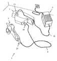
- FIG. 1is a perspective view of a tool set according to the invention, in the form of pruning scissors, during a charging phase;
- FIG. 2is a perspective view of the tool set of FIG. 1 , during use by an operator;
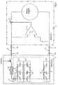
- FIG. 3is a synoptic diagram of a non-limiting embodiment of the tool in which the first sub-unit is equipped with a device for the automatic cutoff, at minimum low voltage, of its electric supply coming from the second sub-unit to which it is connected during use of the tool;
- FIG. 4is a synoptic diagram of a non-limiting embodiment of the tool in which the second sub-unit is equipped with a module for the automatic cutoff, at minimum low voltage, of the electric supply of the first sub-unit to which it is connected during use of the tool;
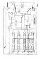
- FIG. 5is a synoptic diagram of a non-limiting embodiment of the tool, in which the second sub-unit is equipped with a module for the automatic cutoff of the charging at maximum high voltage of its electric supply, the latter being connected to the third charging sub-unit;
- FIG. 6is a synoptic diagram of a non-limiting embodiment of the tool, in which the second sub-unit is equipped with a module for the automatic cutoff of the charging at low current of its electric supply, the latter being connected to the third charging sub-unit;
- FIG. 7is a synoptic diagram of a non-limiting embodiment of the tool, in which the third charger sub-unit is equipped with a device for the automatic cutoff of the charging at maximum high voltage of the electric supply of the second sub-unit;
- FIG. 8is a synoptic diagram of a non-limiting embodiment of the tool, in which the third charger sub-unit is equipped with a device for the automatic cutoff of the charging at minimum low current of the electric supply of the second sub-unit;
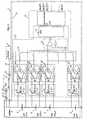
- FIG. 9is a synoptic diagram of a non-limiting embodiment of the tool, in which the second sub-unit is equipped with one or several modules capable of carrying out the following functions: a) the cutoff at minimum low voltage of the electric supply of the first sub-unit, when the first sub-unit is used by the operator; b) the automatic cutoff of the charging at maximum high voltage and, c) the automatic cutoff of the charging at minimum low current when the second sub-unit is connected to the third sub-unit during the charging operation; d) protection against short circuits; e) placing the battery in no consumption or very little consumption mode when the first sub-unit is not in use; 1) stopping the charging at excessive temperature;
- FIG. 10is a synoptic diagram of the second functional sub-unit that is integral with the tool set
- FIG. 11is an electronic skeleton diagram of some constituent elements of the second sub-unit shown in FIG. 10 ;
- FIG. 12is the schematic algorithm of one particularly efficient charging method.
- the power autonomous portable electric tool set 1includes at least three distinct functional sub-units 2 , 3 , and 4 , namely, a first sub-unit 2 forming an electric actuator and generating the mechanical operation of the tool, a second sub-unit 3 forming the electric energy source and essentially including a rechargeable lithium-ion or lithium polymer battery 5 , and a third sub-unit 4 forming a charger capable of recharging the battery 5 .
- the first sub-unit 2is connected to the second sub-unit 3 , at least during use of the tool, by a flexible electric cord 6 , on the one hand, and it is provided with a cutoff mechanism that makes it possible to disconnect the electric supply of the actuator 7 , as shown in FIG. 3 , which constitutes it, automatically and/or at will by the operator, on the other hand.
- the electric actuator 7 of the first sub-unit 2can be constituted, for example, by a direct current brush electric motor, or by a tri-phase synchronous brushless electric motor, with position sensors, or by a tri-phase synchronous brushless electric motor without position sensors.
- the second sub-unit 3can be carried by the operator, and, as shown in FIG. 3 , it is constituted by a lithium-ion or lithium polymer electrochemical battery 5 formed by serially associating cells 8 , each cell comprising one element or a plurality of elements 9 associated in parallel, on the one hand, and one or a plurality of electric or electronic modules for controlling and/or managing the battery, these modules being located in the vicinity of said battery, on the other hand. For example, they are fixed on the support of the battery and within the casing enclosing the second sub-unit 3 .
- the electric or electrical modulescan also be incorporated directly into the casing of the second sub-unit 3 , for example, by wedging.
- the connections and wiringare made easier and less fragile, and the measuring and control signals are less exposed to disturbances, losses or interferences and less subject to drifts, due to a reduced transmission distance.
- the third charger sub-unit 4comprises at least one electric energy source, in which the voltage and current are adapted to recharging the lithium-ion or lithium polymer battery 5 .
- This third charger sub-unit 4is electrically connected to the second 3 sub-unit by a disconnectable flexible cord 10 .
- the second and third sub-units 3 and 4can be in the form of a single unit integrating the two sub-units 3 and 4 , or in the form of two distinct physical entities that are electrically connected to one another by a disconnectable flexible cord during the charging phases. This latter alternative embodiment is naturally preferred in the context of the present application for reducing the load to be carried by the operator.
- the electric flexible cord 6 that connects the first sub-unit 2 to the second sub-unit 3can be provided with:
- the first sub-unit 2is equipped with a device for the automatic cutoff, at minimum low voltage, of its electric supply coming from the second sub-unit 3 to which it is connected during use of the tool.
- a device for the automatic cutoff, at minimum low voltage, of its electric supply coming from the second sub-unit 3 to which it is connected during use of the toolIt should be noted that lithium-ion or lithium polymer batteries should never be completely discharged; a mere discharge below the minimum voltage value recommended by the manufacturer leads irremediably to the deterioration of the battery. Therefore, it is necessary to equip the tool set with a device limiting the discharge voltage to remedy this drawback.
- the precision of this minimum discharge voltage limitationshould be on the order of 10%.
- a voltage comparator 11preferably with hysteresis, that compares the voltage of the battery 5 to a reference voltage, which is determined by the multiplication of minimum discharge voltage of an element recommended by the manufacturers of lithium-ion or lithium polymer battery elements by the number of battery cells in a series.
- This systemthus enables the cutoff of the electric supply of the first sub-unit 2 by acting directly on a cutoff member, for example, a MOS transistor or a relay 12 .
- This device 12can be located directly on the first sub-unit 2 , which is the case for this first embodiment, but also on the second sub-unit 3 , which corresponds to the next example of embodiment.
- the battery discharge voltage limitationis obtained during use of the tool by one of the electric or electronic modules for controlling and/or managing the battery 5 of the second sub-unit 3 to which it is connected by the flexible cord 6 during use of the tool.
- the embodimentis identical to that described hereinabove, the difference being that the electronic cutoff system is located on the second sub-unit 3 .
- the second sub-unit 3is equipped with a module for the automatic cutoff of the charging, at maximum high voltage, of its electric supply, the latter being connected to the third charger sub-unit 4 .
- a module for the automatic cutoff of the chargingat maximum high voltage, of its electric supply, the latter being connected to the third charger sub-unit 4 .
- lithium-ion or lithium polymer batteriesshould never be charged beyond a maximum voltage recommended or required by the manufacturer of the lithium-ion or lithium polymer battery used, as exceeding this charge voltage would irremediably lead to the deterioration of the battery elements. Therefore, it is necessary to equip the tool set 1 with a charge voltage limiting device in order to remedy this drawback.
- This maximum charge voltage limitationmust be very precisely set to at least 1%; it is obtained by an electronic system constituted by a voltage comparator 13 , preferably with hysteresis, that compares the battery voltage to a reference voltage, which is determined by the multiplication of the maximum charge voltage of an element as recommended by the manufacturer of the elements of the lithium-ion or lithium polymer battery that is used by the number of serially associated cells of the battery 5 .
- This systemthus enables the cutoff of the electric supply of the charging of the second sub-unit by acting directly on a cutoff member, for example, a MOS transistor or a relay 14 .
- This embodimentrequires an off-load voltage of the third charger sub-unit 4 that is greater than the reference voltage.
- This devicecan be located directly on the second sub-unit 3 , which is the case in this embodiment, but can also be mounted directly on the third charger sub-unit 4 , as explained hereinafter.
- the second sub-unit 3is equipped with a module for the automatic cutoff of its electric supply at minimum charge current, the latter being connected to the third charger sub-unit 4 .
- a module for the automatic cutoff of its electric supply at minimum charge currentthe latter being connected to the third charger sub-unit 4 .
- This limitation at minimum charge currentis obtained by a current comparing electronic system 15 constituted by a current comparator, preferably with memory, that compares, via a shunt or a current sensor 16 , the battery charging current to a reference current, which is determined by the multiplication of the end of charging current recommended by the manufacturer of the lithium-ion or lithium polymer battery elements used by the number of associated parallel elements constituting the cells of the battery 5 .
- This systemthus enables the cutoff of the electric supply of the charging of the second sub-unit 3 by acting directly on a cutoff member, for example, a MOS transistor or a relay 17 .
- this modulecan be located directly on the second sub-unit 3 , which is the case in this embodiment, but can also be directly mounted on the third charger sub-unit 4 , as explained in another embodiment disclosed hereinafter.
- a fifth embodimentit is the third charger sub-unit 4 that implements the limitation at maximum charge voltage by cutting off the electric supply of the second sub-unit 3 to which it is connected during the charging operation.
- This embodimentis identical to that described hereinabove, the difference being that the electronic cutoff system is located on the third charger sub-unit 4 .
- FIG. 8it is the third charger sub-unit 4 that implements the limitation at minimum charging current by cutting off the electric supply of the second sub-unit 3 to which it is connected during the charging operation.
- This embodimentis identical to that described hereinabove, the difference being that the electronic cutoff system is located on the third charger sub-unit 4 .
- These two last embodimentsare integrated into the third charger sub-unit 4 that transforms the alternating electric energy of the network into direct, pulsating or rectified voltage and current, adapted to recharging the lithium-ion or lithium polymer battery 5 , when the third charger sub-unit 4 is electrically connected to the second sub-unit 3 by a flexible cord 10 .
- the third charger sub-unit 4is electrically connected by a disconnectable flexible cord 10 to the second sub-unit 3 , for example, by a connector 23 .
- a seventh embodiment( FIG. 9 ) some of the six previously described embodiments will be allowed to cohabit, in order to obtain the control and/or management of the battery 5 in limiting the discharge voltage and in limiting of charge voltage and current. Concurrently with these limitations, it will be necessary to provide protection against the battery short circuits that could cause ill-timed heating and cause the battery 5 to catch fire. This protection against short circuits can be usefully obtained by a fuse or a circuit breaker 18 , or a similar component, mounted on at least one terminal of the battery 5 , preferably prior to any other connection.
- the battery 5be placed in no consumption or very little consumption mode, in order to prevent the battery voltage from dropping below the minimum voltage beyond which the battery 5 would deteriorate.
- This functioncan be carried out in a non-limiting manner by a switch 19 arranged at one of the terminals of the battery 5 , and preferably after the fuse or the breaker 18 , if the latter are installed.
- the manufacturers of lithium-ion or lithium polymer battery elementsalso recommend that, during charging and discharging, the battery 5 be protected against usage and recharging outside of certain temperature ranges.
- the temperature range recommended for use during dischargingis between ⁇ 15° C. and +60° C., and between 0° C. and 45° C. for charging.
- a temperature sensor 20capable of electrically isolating the lithium-ion or lithium polymer battery 5 on a terminal of the battery, in the vicinity of the fuse or the breaker 18 .
- the limitation at minimum charging currentcan be replaced by a system limiting the charging duration in time, as a function of the capacity of the elements, of the number of associated parallel elements in a cell of the battery 5 and of the maximum current delivered by the third charger sub-unit 4 .
- FIGS. 10 , 11 , 12According to an eighth, non-limiting and extremely efficient embodiment ( FIGS. 10 , 11 , 12 ) of the invention that has enabled the applicant to very safely obtain a cycle life of more than 1000 charging and discharging cycles, with a loss of capacity of less than 20%, over several years of testing; knowing that lithium-ion batteries are known for their risk of catching fire in view of their organic electrolyte and the very flammable lithium.
- the second sub-unit 3is equipped with a single control module 26 for controlling and/or managing the battery 5 in the form of at least one electronic board including at least one digital processing unit 21 , such as, for example, a microprocessor, a microcontroller, a digital signal processor, associated with a memory and with annexed digital and/or analog circuits capable, together, of performing some, and preferably all of the following tasks:
- a digital processing unit 21such as, for example, a microprocessor, a microcontroller, a digital signal processor, associated with a memory and with annexed digital and/or analog circuits capable, together, of performing some, and preferably all of the following tasks:
- Performing these various tasksis initiated and directed by the digital processing unit 21 , under the control of a program managing the functioning of the tool set 1 , while taking into account the user's commands and the values of various parameters measured in the area of the second sub-unit 3 , and possibly in the area of the first and/or third sub-unit(s) 2 and/or 4 .
- the control module 26constantly exploits the voltage measuring values for each cell 8 composing the battery 5 .
- the inventionprovides that for a battery 5 formed of serially associated n cells 8 , the voltage measuring values of each cell 8 are furnished by an acquisition electronic chain 27 ( FIG. 11 ) constituted mainly by identical n analog modules 28 mounted at the terminals of the n cells 8 , respectively, of the battery 5 and capable of measuring the voltage of the corresponding cell 8 , respectively; the values of the voltages measured by each of the n analog modules 28 being then directed, one after the other, via at least one analog multiplexer 29 and after amplification by an adapted circuit 30 , toward an input analog/digital converter 21 ′ of the digital processing unit 21 of the controlling and/or managing module 26 .
- the converter 21 ′can be either integrated into the unit 21 , or can form a circuit separated from the latter.
- the control module 26performs a sequential or cyclical check of the voltages of the various cells 8 , causing a high frequency refresh of the voltage data for each cell 8 available in the area of the digital processing unit 21 , thus making it possible to quickly take into account and react in the case of an abnormal voltage measuring value.
- the n analog modules 28 for measuring voltagesperform a subtraction for each cell 8 , respectively, between the voltage measured at its positive terminal and the voltage measured at its negative terminal, by a differential electronic circuit with operational amplifier 28 ′ using resistances 28 ′′ or input resistive elements.
- the differential electronic circuit with operational amplifier 28 ′ of each voltage measuring module 28comprises resistances or input resistive elements 28 ′′ having an impedance close to or greater than 1 Mohm, so as to obtain very low leakage currents which, by way of non-limiting example, are less than 1/20000th per hour of the total capacity of the battery 5 , the voltage measuring values of each cell 8 being preferably delivered with a measuring precision of at least 50 mV.
- the measuring precision of the desired voltagei.e., advantageous by at least 50 mV, is obtained by calibration during the manufacture of the electronic board of the control module 26 for controlling and managing the battery 5 , making it possible to individually compensate for the errors in voltage measuring module 28 .
- this calibrationcan involve programmatically inputting error correcting parameters in the digital processing unit 21 , as a function of the measurement of one or several very precise reference voltages which, for this calibration operation, are substituted for the voltages that are normally measured at the terminals of each cell 8 .
- the analog/digital converter 21 ′will output at least 10 data bits.
- the task of balancing the charging of the cells 8 with respect to one anotheris managed by the digital processing unit 21 which, based on the voltage measuring values of each cell 8 , and if necessary for each of them, controls the change in the charging current by dissipating circuits using electronic switchers 31 associated with resistive elements 31 ′.
- the method used to obtain a balanced charging of the battery 5can be, for example, that described in the commonly owned French Patent No. 2 862 813 filed by the Applicant on Nov. 20, 2003.
- the task of managing the discharginginvolves constantly checking the voltage data of each cell 8 by the digital processing unit 21 , interrupting the discharging when the unit detects that one of these voltages of a cell 8 has reached the minimum discharge threshold recommended by the manufacturer of lithium-ion or lithium polymer elements, and cutting off the discharging by deactivating the discharge switching component 32 , resulting in the tool of the first sub-unit 2 being stopped and, for example, in a non-limiting manner, by activating a sound or visual warning signal.
- the tasks of managing the charging, evaluating and displaying the capacity of the battery 5 and of protecting against excess current during the dischargingare continuously managed by the digital processing unit 21 due to an analog electronic circuit 33 measuring the charge and discharge current of the battery 5 .
- chargingis ended by opening the charge switching component 34 that is controlled by the digital processing unit 21 when, by the analog electronic circuit 33 measuring the charging and discharging current, said digital processing unit 21 detects a drop of the charging current down to a recommended threshold, for example 50 mA, for the battery 5 , on the one hand, or when the temperature of the battery 5 exceeds an authorized limiting value, for example 45° C., or yet when charging during for a period of time that is greater than a given fraction of the theoretical charging time, for example, about 20%.
- a recommended thresholdfor example 50 mA
- an authorized limiting valuefor example 45° C.
- the task of evaluating and displaying the capacity of the battery 5is managed by the digital processing unit 21 , the latter calculating said capacity by constantly taking into account, during charging and during use of the tool of the first sub-unit 2 the information related to the instantaneous charging and discharging current of the battery 5 delivered by the analog electronic circuit 33 for measuring the charging and discharging current, on the one hand, and the voltage measuring values of each cell 8 and, not necessarily but for a more accurate calculation, their known average internal resistance.
- the task of protecting against excess current during discharging of the battery 5 while the tool of the first sub-unit 2 is being used, adapted to preserve the lithium-ion or lithium polymer battery 5 from premature aging or from overheatinginvolves either cutting off the discharging current in the case of a very substantial pulsed overload of the maximum discharging current allowed for the battery 5 , or of an excess of the maximum limiting temperature allowed for the latter, or limiting the discharging current as a function of the energy consumed by the tool of the first sub-unit 2 during a certain sliding time period, knowing that the value of the energy and the sliding time period are experimentally predetermined as a function of the tool, its use and the cycle life desired for the lithium-ion or lithium polymer battery 5 of the second sub-unit 3 .
- the discharging current limitationis managed by the digital processing unit 21 by applying a pulse width modulation (PWM) control, generated either directly by the digital processing unit 21 , or by a special component, through a control stage 35 , to the discharge switching component 32 made, for example, in the form of an N-channel MOSFET type component.
- PWMpulse width modulation
- the digital processing unit 21automatically undertakes a storage managing task, which involves verifying whether or not the residual capacity of the battery 5 is greater than the storage capacity recommended by the manufacturers of lithium-ion or lithium polymer elements and, if the residual capacity is indeed greater than the storage capacity, having the digital processing unit 21 initiate an automatic discharge of the battery by resistive circuits 31 ′ connected in parallel on each cell 8 , until the storage capacity is reached, and, consequently, stopping all of the electronic circuits while placing the digital processing unit 21 in low consumption stand-by mode, and, if the capacity is below the storage capacity, having the digital processing unit 21 set off a sound and/or visual alarm.
- a storage managing taskwhich involves verifying whether or not the residual capacity of the battery 5 is greater than the storage capacity recommended by the manufacturers of lithium-ion or lithium polymer elements and, if the residual capacity is indeed greater than the storage capacity, having the digital processing unit 21 initiate an automatic discharge of the battery by resistive circuits 31 ′ connected in parallel on each cell 8 , until the storage capacity is reached, and, consequently,
- the digital processing unit 21is capable of detecting the live connection of the third charger sub-unit 4 to the battery 5 by a voltage measurement carried out by the control module 26 at least at one of the terminals 37 , preferably a positive terminal, of the second sub-unit 3 that are adapted to be connected to said third charger sub-unit 4 .
- this functionBy detecting the instant when at least one cell 8 has reached the minimum voltage recommended by the manufacturer, this function, possibly carried out by a particular adapted measuring circuit 36 , makes it possible to initiate an automatic recharging of the battery 5 , as long as the tool is stored in non-use phase.
- the digital processing unit 21that uses this information orders the interruption of the charging and sets off a sound and/or visual alarm.
- pair of terminals 37 for connecting to the third charger sub-unit 4 and the pair of terminals 37 for connecting to the tool of the first sub-unit 2have a common negative terminal connected to the ground, but have distinct positive terminal, to each of which a corresponding switching component 32 or 34 is coupled.
- the task of managing the information and diagnosticscan involve storing in the memory of the digital processing unit 21 information that is acquired during use of the tool, such as, for example, the number of recharges, the computation of the number of hours the tool was used, the change in the capacity of the battery 5 in time, the average energy consumed by the tool, or similar information; this information can be transmitted by a wire, radiofrequency, or infrared connection 40 toward a separate operating terminal, such as, for example a personal computer, an electronic personal assistant, or a GSM, which can possibly be connected to the Internet.
- a separate operating terminalsuch as, for example a personal computer, an electronic personal assistant, or a GSM, which can possibly be connected to the Internet.
- the control module 26 for controlling and/or managing the battery 5 of the second sub-unit 3 forming a rechargeable electric energy sourcecan be associated with an electronic module for controlling the actuator 7 and sensors thereof, for example, but in a non-limiting manner, on the same electronic board, using the same digital processing unit 21 , if necessary, knowing that the electric actuator 7 of the first sub-unit 2 can be constituted, for example, by a brush direct current electric motor, or by a brushless tri-phase synchronous motor with position sensors, or yet by a brushless tri-phase synchronous motor without position sensors.
- the digital processing unit 21will also include a device for controlling the running of the program for managing the tool set 1 and for the sequenced acquisition of the measuring values, which is symbolically shown in FIG. 12 .
- additional circuits for interrupting the connection of the second sub-unit 3 with the first or third sub-unit 2 or 4can be provided, in parallel to the aforementioned normal controlling system constructed around the digital processing unit 21 .
- control module 26 for controlling the battery 5can comprise for each cell 8 , redundant safety circuits 38 for stopping the charging, each of them being capable of individually controlling the general interruption of the charging, in the case of excess voltage in a cell 8 , by directly deactivating the charge switching component 34 without biasing the digital processing unit 21 .
- control module 26can comprise a discharge stopping redundant circuit 38 ′ ( FIG. 10 ) that is capable of ordering the interruption of the discharging if the measuring analog electronic circuit 33 detects a discharge current equal to or greater than a maximum value allowed for the battery 5 , by directly deactivating the discharge switching component 32 without biasing the digital processing unit 21 .
- the third charger sub-unit 4 adapted to recharging the lithium-ion or lithium polymer battery 5generates a voltage with a precision approximating 0.5% and a controlled current, both obtained by a special circuit for regulating voltage and current.
- Such circuitsare already known and do not need to be described any further.
- each functional sub-unit 2 , 3 , and 4is mounted (when the sub-units 3 and 4 are distinct) in a specific protective and/or gripping casing, which can be connected to one another in pair by disconnectable flexible cables 6 , 10 for transferring energy and transmitting the command and/or control signals between said sub-units 2 , 3 and 4 .
- the charging of the batterymay or may not be carried out with the cable 6 connecting the sub-units 2 and 3 to each other.
- the casing enclosing the first sub-unit 2also carries the tool and is ergonomically configured, at least in the area of one portion, so as to enable an easy, reliable, and comfortable grip by the user.
- analog control buttons or members, as well as the sound and/or light display and warning devicesare preferably present, partially in the area of the casing of the first sub-unit 2 and partially in the area of the casing of the second sub-unit 3 , as a function of their type and of the necessity for them to be accessible to the operator during actual use of the tool set 1 .
Landscapes
- Engineering & Computer Science (AREA)
- Power Engineering (AREA)
- Life Sciences & Earth Sciences (AREA)
- Environmental Sciences (AREA)
- Ecology (AREA)
- Forests & Forestry (AREA)
- Biodiversity & Conservation Biology (AREA)
- Secondary Cells (AREA)
- Charge And Discharge Circuits For Batteries Or The Like (AREA)
- Battery Mounting, Suspending (AREA)
- Portable Power Tools In General (AREA)
- Sawing (AREA)
- Percussive Tools And Related Accessories (AREA)
- Harvester Elements (AREA)
- Percussion Or Vibration Massage (AREA)
Abstract
Description
- one module among the electric or electronic module(s) for controlling and/or managing the battery equipping the
second sub-unit 3 is configured for the function of automatically cutting off the electric supply of thefirst sub-unit 2 when the battery voltage has reached a minimum low level prior to the deterioration, by significant loss of capacity and increase of spontaneous discharge, of the lithium-ion orlithium polymer battery 5 equipping thesecond sub-unit 3; - one module among the electric or electronic module(s) for controlling and/or managing the
battery 5 equipping thesecond sub-unit 3 is configured for the function of automatically cutting off the electric charging of thebattery 5 when the voltage delivered by thethird charger sub-unit 4, to which it is connected, has reached the maximum value prior to the deterioration, by significant loss of capacity and increase of spontaneous discharge, of the lithium-ion orlithium polymer battery 5 equipping thesecond sub-unit 3; - one module among the electric or electronic module(s) for controlling and/or managing the
battery 5 equipping thesecond sub-unit 3 is configured to carry out the function of automatically cutting off the electric charging of thebattery 5 when the current charging thebattery 5 has reached a minimum low level recommended or required by the manufacture of the lithium-ion orlithium polymer battery 5 equipping thesecond sub-unit 3; and - one module among the electric or electronic module(s) for controlling and/or managing the
battery 5 equipping thesecond sub-unit 3 is configured to carry out the function of protecting thebattery 5 against short circuits.
- one module among the electric or electronic module(s) for controlling and/or managing the battery equipping the
- a
connector 24 couplable to thesecond sub-unit 3; - a
connector 25 couplable to thefirst sub-unit 2; or - a
connector 25 couplable to thefirst sub-unit 2 and also asecond connector 24 couplable to thesecond sub-unit 3.
- a
- managing the charging;
- managing the discharging;
- balancing the charging of each
cell 8; - evaluating and displaying the capacity of the
battery 5; - protecting the
battery 5 when discharging against excess current when the tool is being used; - managing the tool during the storing phases;
- managing the alarms;
- managing and transmitting the information collected; and
- managing the diagnostics.
Claims (60)
Applications Claiming Priority (3)
| Application Number | Priority Date | Filing Date | Title |
|---|---|---|---|
| FR0313608 | 2003-11-20 | ||
| FR0313608AFR2862558B1 (en) | 2003-11-20 | 2003-11-20 | POWER AUTONOMOUS POWER PORTABLE TOOL |
| PCT/FR2004/002954WO2005053131A2 (en) | 2003-11-20 | 2004-11-19 | Power autonomous portable electric tool set |
Publications (2)
| Publication Number | Publication Date |
|---|---|
| US20070108944A1 US20070108944A1 (en) | 2007-05-17 |
| US8089247B2true US8089247B2 (en) | 2012-01-03 |
Family
ID=34531147
Family Applications (2)
| Application Number | Title | Priority Date | Filing Date |
|---|---|---|---|
| US10/579,917Expired - Fee RelatedUS7592773B2 (en) | 2003-11-20 | 2004-11-18 | Portable self-contained electric power tool |
| US10/580,155Expired - Fee RelatedUS8089247B2 (en) | 2003-11-20 | 2004-11-19 | Power autonomous portable electric tool set |
Family Applications Before (1)
| Application Number | Title | Priority Date | Filing Date |
|---|---|---|---|
| US10/579,917Expired - Fee RelatedUS7592773B2 (en) | 2003-11-20 | 2004-11-18 | Portable self-contained electric power tool |
Country Status (10)
| Country | Link |
|---|---|
| US (2) | US7592773B2 (en) |
| EP (2) | EP1685636B2 (en) |
| JP (4) | JP4949035B2 (en) |
| CN (2) | CN1883096B (en) |
| BR (2) | BRPI0416048A (en) |
| CA (2) | CA2546788C (en) |
| ES (2) | ES2607877T3 (en) |
| FR (1) | FR2862558B1 (en) |
| RU (2) | RU2345462C2 (en) |
| WO (2) | WO2005053915A2 (en) |
Cited By (16)
| Publication number | Priority date | Publication date | Assignee | Title |
|---|---|---|---|---|
| US8547066B2 (en) | 2010-11-03 | 2013-10-01 | Felco Motion Sa | Method and apparatus for powering an electric hand-held power tool device |
| US20130285613A1 (en)* | 2011-01-18 | 2013-10-31 | Nissan Motor Co., Ltd. | Battery control device |
| US9166422B2 (en) | 2007-02-26 | 2015-10-20 | Black & Decker Inc. | Battery based portable power supply |
| US9350168B2 (en) | 2011-05-31 | 2016-05-24 | Lg Chem, Ltd. | Voltage equalization apparatus for connecting power storage unit racks and power storage system including the same |
| US9872440B2 (en) | 2012-05-04 | 2018-01-23 | Felco Motion Sa | Handheld power tool |
| US10218189B2 (en)* | 2014-04-07 | 2019-02-26 | Dr. Ing. H.C. F. Porsche Aktiengesellschaft | Electrical energy storage system |
| US10408884B2 (en) | 2016-03-16 | 2019-09-10 | Tti (Macao Commercial Offshore) Limited | Power tool battery pack with wireless communication |
| US10601084B2 (en)* | 2014-07-11 | 2020-03-24 | Panasonic Intellectual Property Management Co., Ltd. | Storage battery pack and method of operating the same |
| US20200106230A1 (en)* | 2018-09-28 | 2020-04-02 | Hubbell Incorporated | Power tool with crimp localization |
| US10827655B2 (en) | 2017-06-26 | 2020-11-03 | Milwaukee Electric Tool Corporation | Battery charger |
| US10910851B2 (en)* | 2017-04-20 | 2021-02-02 | Ablic Inc. | Overcurrent, overcharge, and overdischarge detection and responsive switch control |
| US20210036523A1 (en)* | 2018-01-25 | 2021-02-04 | Volvo Construction Equipment Ab | Equalizer overload management |
| US11431224B2 (en) | 2017-02-15 | 2022-08-30 | Black & Decker Inc. | Power and home tools |
| US11457558B1 (en) | 2019-05-15 | 2022-10-04 | Hydro-Gear Limited Partnership | Autonomous vehicle navigation |
| US12172272B2 (en) | 2020-11-05 | 2024-12-24 | Techtronic Cordless Gp | Power tool control system |
| US12197184B2 (en) | 2020-06-21 | 2025-01-14 | Hubbell Incorporated | Power tool with crimp image |
Families Citing this family (84)
| Publication number | Priority date | Publication date | Assignee | Title |
|---|---|---|---|---|
| FR2862558B1 (en)* | 2003-11-20 | 2006-04-28 | Pellenc Sa | POWER AUTONOMOUS POWER PORTABLE TOOL |
| DE102004031601A1 (en)* | 2004-06-30 | 2006-02-09 | Hilti Ag | Battery pack for electric hand tool |
| US7408326B2 (en)* | 2005-04-08 | 2008-08-05 | Texas Instruments Incorporated | Battery pack system interface with multiple mode control states |
| EP1780867B1 (en)* | 2005-10-28 | 2016-11-30 | Black & Decker Inc. | Battery pack for cordless power tools |
| US7696721B2 (en)* | 2005-11-08 | 2010-04-13 | Emerson Electric Co. | Switching method and apparatus for AC/DC powered corded/cordless appliance and related apparatus |
| JP5574138B2 (en)* | 2006-09-19 | 2014-08-20 | 日立工機株式会社 | Adapter, combination of battery pack and adapter, and electric tool equipped with them |
| ES2678411T3 (en) | 2006-11-10 | 2018-08-10 | Lithium Balance A/S | Battery management system |
| KR100779515B1 (en) | 2006-11-20 | 2007-11-28 | 주식회사 월드에너지 | Portable pruning shears |
| DE102006062354A1 (en) | 2006-12-22 | 2008-06-26 | Andreas Stihl Ag & Co. Kg | Drive arrangement for a portable working device |
| EP2015421B1 (en)* | 2007-07-13 | 2016-03-09 | Black & Decker, Inc. | Reset mechanism for a battery pack |
| FR2920683B1 (en) | 2007-09-06 | 2010-02-12 | Pellenc Sa | MULTIPURPOSE ELECTROPORTATIVE DEVICES. |
| FR2925384B1 (en)* | 2007-12-20 | 2011-11-18 | Pellenc Sa | PORTABLE ELECTRIC CHAIN SAW |
| DE102008003786A1 (en)* | 2008-01-10 | 2009-07-16 | Robert Bosch Gmbh | Method for detecting a thermal overload situation in an electric hand tool |
| US8222868B2 (en)* | 2008-04-02 | 2012-07-17 | Techtronic Power Tools Technology Limited | Battery tester for rechargeable power tool batteries |
| TWI590929B (en)* | 2008-05-20 | 2017-07-11 | Max Co Ltd | Tool |
| JP5277795B2 (en)* | 2008-08-22 | 2013-08-28 | 日立工機株式会社 | Electric tool system |
| FR2935106B1 (en)* | 2008-08-22 | 2010-09-17 | Pellenc Sa | PORTABLE ELECTROPORTATIVE TOOL |
| FR2935175B1 (en)* | 2008-08-22 | 2011-02-11 | Pellenc Sa | DEVICE FOR DETERMINING THE RELATIVE POSITION BETWEEN TWO OR MORE OF WHICH IS AT LEAST MOVABLE, AND MACHINES AND APPARATUSES BY APPLYING |
| US8276280B2 (en)* | 2008-09-16 | 2012-10-02 | Republic Of Korea (Management: Rural Development Administration) | Electromotion trim scissors |
| RU2518520C2 (en)* | 2008-10-08 | 2014-06-10 | Макита Корпорейшн | Monitoring system of electric power-driven tool, battery power source of electric power-driven tool, and charging device for batteries of electric power-driven tool |
| US8575899B2 (en) | 2009-07-16 | 2013-11-05 | Schumacher Electric Corporation | Battery charger with automatic voltage detection |
| JP5427521B2 (en)* | 2009-09-04 | 2014-02-26 | 株式会社マキタ | Battery pack |
| JP5461221B2 (en) | 2010-02-12 | 2014-04-02 | 株式会社マキタ | Electric tool powered by multiple battery packs |
| US9136717B2 (en)* | 2010-03-26 | 2015-09-15 | Semiconductor Components Industries, Llc | Semiconductor integrated circuit |
| TWI416841B (en)* | 2010-06-10 | 2013-11-21 | Wistron Corp | Electricity storing device and electronic device |
| JP5453184B2 (en)* | 2010-06-28 | 2014-03-26 | 日立ビークルエナジー株式会社 | Battery control circuit |
| JP5582397B2 (en)* | 2010-08-31 | 2014-09-03 | 日立工機株式会社 | Electric tool and battery pack used for electric tool |
| DE102010042227A1 (en)* | 2010-10-08 | 2012-04-12 | Robert Bosch Gmbh | Method and charging station for electrically charging an electrical energy store |
| EP2637233B1 (en)* | 2010-11-04 | 2017-09-06 | Makita Corporation | Battery pack |
| RU2440653C1 (en)* | 2010-12-01 | 2012-01-20 | Аслан Узеирович Заммоев | Pruning shears with automatic drive |
| JP5579046B2 (en)* | 2010-12-27 | 2014-08-27 | 株式会社マキタ | Electric tool equipment |
| JP5744509B2 (en)* | 2010-12-28 | 2015-07-08 | 株式会社マキタ | Battery for power tools |
| FR2973815B1 (en)* | 2011-04-07 | 2014-08-29 | Pellenc Sa | AUTONOMOUS ELECTROPORTATIVE BLOWER WITH MODULAR AIR OUTPUT SPEED |
| US8884589B2 (en)* | 2011-09-14 | 2014-11-11 | Standard Microsystems Corporation | Method and system for power switch temperature regulation |
| DE102011121934A1 (en) | 2011-12-22 | 2013-06-27 | Andreas Stihl Ag & Co. Kg | Protection circuit for a battery pack |
| DE102011122058A1 (en)* | 2011-12-22 | 2013-06-27 | Andreas Stihl Ag & Co. Kg | "Back-packable battery pack" |
| DE102011122057A1 (en) | 2011-12-22 | 2013-06-27 | Andreas Stihl Ag & Co. Kg | Electric implement with an electrical load and a battery pack |
| DE102011121937A1 (en) | 2011-12-22 | 2013-06-27 | Andreas Stihl Ag & Co. Kg | Protection circuit for a battery pack |
| DE102011121940A1 (en) | 2011-12-22 | 2013-06-27 | Andreas Stihl Ag & Co. Kg | Debalancing protection circuit for a battery pack |
| WO2013139372A1 (en) | 2012-03-19 | 2013-09-26 | Husqvarna Ab | Power adapter for cordless power tools |
| EP2828907B1 (en) | 2012-03-19 | 2017-07-19 | Husqvarna AB | Carrier system for a backpack energy source, energy source and backpack energy source assembly |
| JP5946210B2 (en)* | 2012-05-14 | 2016-07-05 | エムケー精工株式会社 | Power supply |
| CN103427125B (en)* | 2012-05-15 | 2016-04-13 | 清华大学 | The round-robin method of sulfenyl polymer Li-ion battery |
| US9041344B2 (en)* | 2012-05-25 | 2015-05-26 | Timotion Technology Co., Ltd. | Standby battery box for electric cylinder |
| JP2014014890A (en)* | 2012-07-06 | 2014-01-30 | Hitachi Koki Co Ltd | Adapter |
| JP2014017952A (en)* | 2012-07-06 | 2014-01-30 | Hitachi Koki Co Ltd | Backpack power supply |
| EP2685587B1 (en)* | 2012-07-13 | 2016-12-21 | Braun GmbH | Consumer device presentation unit |
| CN103701163B (en)* | 2013-12-06 | 2018-05-01 | 深圳市大疆创新科技有限公司 | Battery, aircraft with battery and battery control method |
| JP2014100785A (en)* | 2014-01-15 | 2014-06-05 | Makita Corp | Power tool using plural battery packs as power source |
| DE102014201196A1 (en)* | 2014-01-23 | 2015-07-23 | Robert Bosch Gmbh | Method for operating a battery management system and battery management system |
| US9893384B2 (en) | 2014-05-18 | 2018-02-13 | Black & Decker Inc. | Transport system for convertible battery pack |
| JP6406568B2 (en)* | 2014-06-18 | 2018-10-17 | 勝行 戸津 | Driving operation method of power supply system for driving control of electric power tool |
| CN104115686A (en)* | 2014-06-20 | 2014-10-29 | 宁波大叶园林设备有限公司 | Lithium electric chain saw containing soft rope hard tube for continuation work |
| FR3028695B1 (en) | 2014-11-19 | 2017-12-22 | Pellenc Sa | SYSTEM AND METHOD FOR BIDIRECTIONAL AND SIMULTANEOUS COMMUNICATION. |
| WO2016199008A1 (en)* | 2015-06-10 | 2016-12-15 | Braun Gmbh | Method for controlling the battery capacity of a secondary battery and battery-driven household electrical appliance |
| TWI558064B (en)* | 2015-07-31 | 2016-11-11 | 宏碁股份有限公司 | Battery balancing device and battery balancing method thereof |
| CN105127958A (en)* | 2015-08-10 | 2015-12-09 | 浙江亚特电器有限公司 | Impact wrench |
| DE102015116508A1 (en)* | 2015-09-29 | 2017-03-30 | Metabowerke Gmbh | Power tool with several battery packs |
| CN106960556A (en)* | 2016-01-12 | 2017-07-18 | 正阳实业投资有限公司 | Electric tool data collection and application system and method |
| CN110365074B (en) | 2016-09-20 | 2022-02-11 | 华为技术有限公司 | Battery, terminal and charging system |
| US10424955B2 (en)* | 2016-10-28 | 2019-09-24 | Starkey Laboratories, Inc. | Charging system with compressible contacts |
| EP3336926B1 (en)* | 2016-12-16 | 2019-03-06 | Defond Electech Co., Ltd | A method and system for use in operably connecting a battery pack to a machine |
| CN107360872A (en)* | 2017-08-24 | 2017-11-21 | 德清绿色阳光农业生态有限公司 | New nursery stock trunk cutter device |
| GB201719483D0 (en)* | 2017-11-23 | 2018-01-10 | Deciwatt Ltd | Portable apparatus for generating electricity |
| CN108080723A (en)* | 2017-12-22 | 2018-05-29 | 宁波星瑞克中空铝条有限公司 | The saw cutting device of aluminum strip in a kind of hollow glass |
| KR102314575B1 (en)* | 2018-01-12 | 2021-10-20 | 주식회사 엘지에너지솔루션 | Charging-Recharging Device for Rechargeable Battery and Equipment for Activation Process of Rechargeable Battery Comprising the Same |
| CN108115622A (en)* | 2018-01-19 | 2018-06-05 | 杭州怡田工具制造有限公司 | A kind of electric tool with detachable battery powdered device |
| JP7036605B2 (en)* | 2018-01-30 | 2022-03-15 | プライムアースEvエナジー株式会社 | Battery state estimation device and battery state estimation method |
| US10875201B2 (en) | 2018-04-04 | 2020-12-29 | Swanstrom Tools Usa Inc. | Relief guard for hand tools |
| FR3082855B1 (en)* | 2018-06-22 | 2021-03-12 | Soc Des Anciens Etablissements L Geismar | MACHINE-TOOL SYSTEM, ESPECIALLY FOR WORK ON A RAILWAY TRACK |
| WO2020041229A1 (en)* | 2018-08-21 | 2020-02-27 | Milwaukee Electric Tool Corporation | Vehicle battery jump starter powered by a removable and rechargeable battery pack |
| DE102019202163A1 (en)* | 2019-02-19 | 2020-08-20 | Audi Ag | Protection device and method for switching off at least one battery cell in a battery system in the event of an electrical short circuit as well as motor vehicle, battery system and battery cell with the protection device |
| WO2021054302A1 (en)* | 2019-09-17 | 2021-03-25 | 京セラインダストリアルツールズ株式会社 | Power supply device, cable-equipped power supply device, and electric tool |
| CN110842838B (en)* | 2019-11-27 | 2022-02-15 | 东台市新杰科机械有限公司 | Electric wrench for building electric tower |
| CN213644585U (en)* | 2019-12-13 | 2021-07-09 | 苏州宝时得电动工具有限公司 | Spray gun and spray gun system |
| EP4074462A4 (en) | 2019-12-13 | 2023-06-21 | Positec Power Tools (Suzhou) Co., Ltd | Control device and electric power tool system |
| CN111758415B (en)* | 2020-04-20 | 2023-07-07 | 玉林市蚕业技术推广站 | Electric cutting device for mulberry branches |
| EP4007114A1 (en) | 2020-11-26 | 2022-06-01 | Guido Valentini | Method for operation of an electronic device equipped with two or more battery packs and respective electronic device |
| CN113366988A (en)* | 2021-05-20 | 2021-09-10 | 格力博(江苏)股份有限公司 | Power device and electric tool |
| CN113506943B (en)* | 2021-07-13 | 2024-03-12 | 格力博(江苏)股份有限公司 | Backpack type power supply equipment and backpack type tool system |
| CN113396716B (en)* | 2021-07-13 | 2022-12-02 | 格力博(江苏)股份有限公司 | A backpack garden tool |
| CN113829392A (en)* | 2021-09-23 | 2021-12-24 | 深圳市瑞田科技有限公司 | Electric scissors convenient to operation |
| FR3134026B1 (en) | 2022-04-05 | 2024-10-04 | Etesia | Motorized robot |
| CN115176614A (en)* | 2022-06-27 | 2022-10-14 | 广西电网有限责任公司玉林供电局 | High-voltage line near-electricity shutdown alarm insulation pole pruning saw |
Citations (19)
| Publication number | Priority date | Publication date | Assignee | Title |
|---|---|---|---|---|
| EP0291131A1 (en) | 1987-05-15 | 1988-11-17 | Emerson Electric Co. | Tool for intermediate voltage |
| EP0310717A1 (en) | 1987-10-06 | 1989-04-12 | Black & Decker Inc. | Battery pack |
| US5466545A (en)* | 1995-01-27 | 1995-11-14 | Fluke Corporation | Compact, shock resistant battery pack |
| US5808469A (en)* | 1995-01-06 | 1998-09-15 | Chrysler Corporation | Battery monitor for electric vehicles |
| US6087815A (en)* | 1997-04-23 | 2000-07-11 | Fiskars Inc. | Portable power system using DC to DC converter |
| US6218806B1 (en)* | 1998-06-03 | 2001-04-17 | Black & Decker Inc. | Method and apparatus for obtaining product use information |
| US6229280B1 (en)* | 1998-03-18 | 2001-05-08 | Makita Corporation | Power tool charging system having a charge level indicator and charge control functions |
| US6268710B1 (en)* | 1999-07-09 | 2001-07-31 | Fujitsu Limited | Battery monitor apparatus |
| US6285161B1 (en)* | 2000-09-11 | 2001-09-04 | O2 Micro International Limited | Battery cell charging system having voltage threshold and bleeder current generating circuits |
| US20010052758A1 (en) | 2000-03-17 | 2001-12-20 | Shigefumi Odaohhara | Power supply apparatus, electrical equipment and power supply method |
| EP1217710A1 (en) | 2000-12-21 | 2002-06-26 | Makita Corporation | Charging system and battery pack |
| US6433517B2 (en)* | 1998-02-28 | 2002-08-13 | Makita Corporation | Battery charger and charging method |
| US20030096158A1 (en)* | 2001-11-21 | 2003-05-22 | Hitachi Koki Co., Ltd. | Battery pack and cordless power tool using the same as power source |
| US6577105B1 (en)* | 1999-05-17 | 2003-06-10 | Matsushita Electric Industrial Co., Ltd. | Circuit and device for protecting secondary battery |
| US20040027094A1 (en)* | 2000-09-04 | 2004-02-12 | Sanders David Edwin | Battery monitoring network |
| US20050077878A1 (en)* | 2003-10-14 | 2005-04-14 | Dave Carrier | Protection methods, protection circuits and protective devices for secondary batteries, a power tool, charger and battery pack adapted to provide protection against fault conditions in the battery pack |
| FR2862813A1 (en) | 2003-11-20 | 2005-05-27 | Pellenc Sa | METHOD FOR BALANCED LOADING OF LITHIUM-ION OR POLYMER LITHIUM BATTERY |
| US7227335B2 (en)* | 2003-07-22 | 2007-06-05 | Makita Corporation | Method and apparatus for diagnosing the condition of a rechargeable battery |
| US7592773B2 (en)* | 2003-11-20 | 2009-09-22 | Pellenc (Sa) | Portable self-contained electric power tool |
Family Cites Families (49)
| Publication number | Priority date | Publication date | Assignee | Title |
|---|---|---|---|---|
| US920062A (en) | 1908-05-18 | 1909-04-27 | J G Brill Co | Passenger-car. |
| US1109237A (en) | 1913-05-06 | 1914-09-01 | Atlas Tack Company | Strip-feeding mechanism. |
| US1217710A (en) | 1914-09-22 | 1917-02-27 | United Lead Company | Metallic compound. |
| ES2054028T3 (en)† | 1989-03-31 | 1994-08-01 | Japan Storage Battery Co Ltd | CAM-LEVER MECHANISM AND MOTOR-DRIVEN HYDRAULIC TOOL. |
| US5680026A (en)† | 1994-03-21 | 1997-10-21 | Tyton Corporation | Tool belt with battery assembly |
| JP3470768B2 (en) | 1994-07-11 | 2003-11-25 | ソニー株式会社 | Charge / discharge device |
| US5773159A (en)† | 1995-07-18 | 1998-06-30 | Beard; Paul | Multicell configuration for lithium cells or the like |
| JP3421519B2 (en)† | 1996-02-13 | 2003-06-30 | 三洋電機株式会社 | Overcharge prevention circuit, overdischarge prevention circuit and charge / discharge control circuit |
| WO1997032383A1 (en)† | 1996-02-28 | 1997-09-04 | Meridian Wireless Technologies, Inc. | Automatic deep discharge circuit for rechargeable batteries |
| KR100262527B1 (en)† | 1996-06-29 | 2000-08-01 | 김영환 | Sense amplifier control circuits |
| US5814973A (en)* | 1996-09-20 | 1998-09-29 | Ericsson Inc. | Power unit and charger for a battery powered electrical apparatus and method |
| WO1998047404A1 (en)† | 1997-04-21 | 1998-10-29 | Davis Mckay H | Battery belt assembly and related methods |
| JP3767977B2 (en)† | 1997-06-24 | 2006-04-19 | 三洋電機株式会社 | Pack battery |
| US5898294A (en)† | 1997-08-19 | 1999-04-27 | Polystor Corporation | Control loop for pulse charging lithium ion cells |
| US6007940A (en)† | 1997-11-26 | 1999-12-28 | Celgard Llc | Portable power tool having low rate, rechargeable batteries |
| US6046575A (en)† | 1998-03-31 | 2000-04-04 | Motorola, Inc. | Fail safe circuit and battery pack using same |
| DE19945994A1 (en)† | 1998-09-24 | 2000-06-21 | Horst Dalferth | Power supply for electrical hand-held device, especially tool, has accumulator with cable, adapter that fits into tool's replaceable accumulator compartment with suitable contacts |
| US6268713B1 (en)† | 1999-02-26 | 2001-07-31 | Motorola, Inc. | Method for Li-Ion safety switch fault detection in smart batteries |
| JP2000249724A (en)* | 1999-02-26 | 2000-09-14 | Canon Inc | Information device, remaining amount notification method, and storage medium |
| US6254832B1 (en)† | 1999-03-05 | 2001-07-03 | Rainin Instrument Co., Inc. | Battery powered microprocessor controlled hand portable electronic pipette |
| JP3383607B2 (en)* | 1999-04-08 | 2003-03-04 | セイコーインスツルメンツ株式会社 | Battery condition monitoring circuit, battery device, and electronic device |
| RU2156533C1 (en)* | 1999-04-29 | 2000-09-20 | Никифоров Виктор Евгеньевич | Device for equalizing of voltage unbalance on connected cells of storage battery or batteries |
| DE19921675A1 (en) | 1999-05-11 | 2000-11-16 | Hornung Hans Georg | Method for acquiring parameters and measured quantities of battery packs and the like |
| US6242893B1 (en)† | 1999-06-24 | 2001-06-05 | Bren-Tronics, Inc. | Lithium-ion and lithium polymer battery recharging |
| US6324339B1 (en)† | 1999-11-29 | 2001-11-27 | Eveready Battery Company, Inc. | Battery pack including input and output waveform modification capability |
| US6399238B1 (en) | 1999-12-13 | 2002-06-04 | Alcatel | Module configuration |
| TW429637B (en)† | 1999-12-17 | 2001-04-11 | Synergy Scientech Corp | Electrical energy storage device |
| JP2001218377A (en)* | 2000-01-31 | 2001-08-10 | Oyo Denki Kk | Power unit for charge and discharge of secondary battery |
| US6307349B1 (en) | 2000-02-24 | 2001-10-23 | Intermec Ip Corp. | Battery pack having memory |
| DE10110642B4 (en)† | 2000-03-13 | 2005-06-16 | Nippon Telegraph And Telephone Corp. | Lithium-ion cell capacity estimation for electronic devices, involves estimating capacity of cell based on elapsed time from time when charge voltage reaches specified value to time when charge condition is changed |
| JP4126144B2 (en) | 2000-05-11 | 2008-07-30 | インターナショナル・ビジネス・マシーンズ・コーポレーション | Charging system, intelligent battery, and charging method |
| JP3681624B2 (en)* | 2000-08-31 | 2005-08-10 | 富士通株式会社 | Charging circuit, charging / discharging circuit, and battery pack |
| JP2002093466A (en)* | 2000-09-08 | 2002-03-29 | Matsushita Electric Ind Co Ltd | Charge control circuit |
| JP4366560B2 (en)† | 2001-02-06 | 2009-11-18 | ミツミ電機株式会社 | Secondary battery protection circuit |
| US6441589B1 (en)† | 2001-04-02 | 2002-08-27 | Bellsouth Intellectual Property Corporation | Portable battery recharge station |
| JP4447182B2 (en)* | 2001-04-05 | 2010-04-07 | 株式会社マキタ | Battery powered power tool |
| JP3926114B2 (en)* | 2001-04-18 | 2007-06-06 | 株式会社マキタ | Management method of multiple charging devices |
| JP2003061255A (en)* | 2001-08-21 | 2003-02-28 | Sony Corp | Secondary battery pack, integrated circuit thereof, and electronic equipment |
| JP4605952B2 (en)* | 2001-08-29 | 2011-01-05 | 株式会社日立製作所 | Power storage device and control method thereof |
| JP4263859B2 (en)* | 2001-10-09 | 2009-05-13 | 古河電池株式会社 | Storage battery maintenance management method |
| JP2003189462A (en)* | 2001-12-20 | 2003-07-04 | Mitsubishi Cable Ind Ltd | Secondary battery protection circuit |
| KR20030062549A (en)† | 2002-01-17 | 2003-07-28 | 엘지전자 주식회사 | Battery charging/discharging apparatus for controlling battery calibration |
| JP3844063B2 (en)* | 2002-02-01 | 2006-11-08 | ミツミ電機株式会社 | Secondary battery protection circuit |
| DE10206485B4 (en)* | 2002-02-16 | 2007-06-21 | Robert Bosch Gmbh | Power supply and electrical appliance |
| EP1363379A3 (en)† | 2002-05-13 | 2004-01-02 | Luxon Energy Devices Corporation | Power module for generating impulses of various levels |
| TWI230493B (en)* | 2002-10-11 | 2005-04-01 | Hitachi Koki Kk | Charging apparatus |
| US6765366B2 (en)* | 2002-10-25 | 2004-07-20 | Motorola, Inc. | Dual mount charger with inverting display |
| US7157882B2 (en)* | 2002-11-22 | 2007-01-02 | Milwaukee Electric Tool Corporation | Method and system for battery protection employing a selectively-actuated switch |
| DE10354871A1 (en)† | 2002-11-22 | 2004-10-28 | Milwaukee Electric Tool Corp., Brookfield | Method and system for protecting a battery |
- 2003
- 2003-11-20FRFR0313608Apatent/FR2862558B1/ennot_activeExpired - Fee Related
- 2004
- 2004-11-18WOPCT/FR2004/002946patent/WO2005053915A2/enactiveApplication Filing
- 2004-11-18BRBRPI0416048-7Apatent/BRPI0416048A/ennot_activeApplication Discontinuation
- 2004-11-18USUS10/579,917patent/US7592773B2/ennot_activeExpired - Fee Related
- 2004-11-18ESES04805483.7Tpatent/ES2607877T3/ennot_activeExpired - Lifetime
- 2004-11-18RURU2006121544/09Apatent/RU2345462C2/ennot_activeIP Right Cessation
- 2004-11-18CNCN200480034381XApatent/CN1883096B/ennot_activeExpired - Fee Related
- 2004-11-18CACA2546788Apatent/CA2546788C/ennot_activeExpired - Fee Related
- 2004-11-18EPEP04805483.7Apatent/EP1685636B2/ennot_activeExpired - Lifetime
- 2004-11-18JPJP2006540519Apatent/JP4949035B2/ennot_activeExpired - Fee Related
- 2004-11-19EPEP04805491.0Apatent/EP1685637B2/ennot_activeExpired - Lifetime
- 2004-11-19CNCN2004800341439Apatent/CN1883095B/ennot_activeExpired - Fee Related
- 2004-11-19RURU2006121550/09Apatent/RU2389118C2/ennot_activeIP Right Cessation
- 2004-11-19CACA2545137Apatent/CA2545137C/ennot_activeExpired - Fee Related
- 2004-11-19JPJP2006540521Apatent/JP5208421B2/ennot_activeExpired - Fee Related
- 2004-11-19ESES04805491.0Tpatent/ES2601727T3/ennot_activeExpired - Lifetime
- 2004-11-19USUS10/580,155patent/US8089247B2/ennot_activeExpired - Fee Related
- 2004-11-19BRBRPI0416741-4Apatent/BRPI0416741A/ennot_activeApplication Discontinuation
- 2004-11-19WOPCT/FR2004/002954patent/WO2005053131A2/enactiveApplication Filing
- 2010
- 2010-01-15JPJP2010006668Apatent/JP5118161B2/ennot_activeExpired - Fee Related
- 2011
- 2011-09-30JPJP2011215999Apatent/JP2012040683A/enactivePending
Patent Citations (20)
| Publication number | Priority date | Publication date | Assignee | Title |
|---|---|---|---|---|
| EP0291131A1 (en) | 1987-05-15 | 1988-11-17 | Emerson Electric Co. | Tool for intermediate voltage |
| EP0310717A1 (en) | 1987-10-06 | 1989-04-12 | Black & Decker Inc. | Battery pack |
| US5808469A (en)* | 1995-01-06 | 1998-09-15 | Chrysler Corporation | Battery monitor for electric vehicles |
| US5466545A (en)* | 1995-01-27 | 1995-11-14 | Fluke Corporation | Compact, shock resistant battery pack |
| US6087815A (en)* | 1997-04-23 | 2000-07-11 | Fiskars Inc. | Portable power system using DC to DC converter |
| US6433517B2 (en)* | 1998-02-28 | 2002-08-13 | Makita Corporation | Battery charger and charging method |
| US6229280B1 (en)* | 1998-03-18 | 2001-05-08 | Makita Corporation | Power tool charging system having a charge level indicator and charge control functions |
| US6218806B1 (en)* | 1998-06-03 | 2001-04-17 | Black & Decker Inc. | Method and apparatus for obtaining product use information |
| US6577105B1 (en)* | 1999-05-17 | 2003-06-10 | Matsushita Electric Industrial Co., Ltd. | Circuit and device for protecting secondary battery |
| US6268710B1 (en)* | 1999-07-09 | 2001-07-31 | Fujitsu Limited | Battery monitor apparatus |
| US20010052758A1 (en) | 2000-03-17 | 2001-12-20 | Shigefumi Odaohhara | Power supply apparatus, electrical equipment and power supply method |
| US20040027094A1 (en)* | 2000-09-04 | 2004-02-12 | Sanders David Edwin | Battery monitoring network |
| US6285161B1 (en)* | 2000-09-11 | 2001-09-04 | O2 Micro International Limited | Battery cell charging system having voltage threshold and bleeder current generating circuits |
| US20020079867A1 (en) | 2000-12-21 | 2002-06-27 | Makita Corporation | Charging system and battery pack |
| EP1217710A1 (en) | 2000-12-21 | 2002-06-26 | Makita Corporation | Charging system and battery pack |
| US20030096158A1 (en)* | 2001-11-21 | 2003-05-22 | Hitachi Koki Co., Ltd. | Battery pack and cordless power tool using the same as power source |
| US7227335B2 (en)* | 2003-07-22 | 2007-06-05 | Makita Corporation | Method and apparatus for diagnosing the condition of a rechargeable battery |
| US20050077878A1 (en)* | 2003-10-14 | 2005-04-14 | Dave Carrier | Protection methods, protection circuits and protective devices for secondary batteries, a power tool, charger and battery pack adapted to provide protection against fault conditions in the battery pack |
| FR2862813A1 (en) | 2003-11-20 | 2005-05-27 | Pellenc Sa | METHOD FOR BALANCED LOADING OF LITHIUM-ION OR POLYMER LITHIUM BATTERY |
| US7592773B2 (en)* | 2003-11-20 | 2009-09-22 | Pellenc (Sa) | Portable self-contained electric power tool |
Non-Patent Citations (1)
| Title |
|---|
| Canadian Office Action with partial English-language translation. |
Cited By (25)
| Publication number | Priority date | Publication date | Assignee | Title |
|---|---|---|---|---|
| US9166422B2 (en) | 2007-02-26 | 2015-10-20 | Black & Decker Inc. | Battery based portable power supply |
| US8547066B2 (en) | 2010-11-03 | 2013-10-01 | Felco Motion Sa | Method and apparatus for powering an electric hand-held power tool device |
| US20130285613A1 (en)* | 2011-01-18 | 2013-10-31 | Nissan Motor Co., Ltd. | Battery control device |
| US9077184B2 (en)* | 2011-01-18 | 2015-07-07 | Nissan Motor Co., Ltd. | Control device to control deterioration of batteries in a battery stack |
| US9350168B2 (en) | 2011-05-31 | 2016-05-24 | Lg Chem, Ltd. | Voltage equalization apparatus for connecting power storage unit racks and power storage system including the same |
| US9872440B2 (en) | 2012-05-04 | 2018-01-23 | Felco Motion Sa | Handheld power tool |
| US10218189B2 (en)* | 2014-04-07 | 2019-02-26 | Dr. Ing. H.C. F. Porsche Aktiengesellschaft | Electrical energy storage system |
| US10601084B2 (en)* | 2014-07-11 | 2020-03-24 | Panasonic Intellectual Property Management Co., Ltd. | Storage battery pack and method of operating the same |
| US10408884B2 (en) | 2016-03-16 | 2019-09-10 | Tti (Macao Commercial Offshore) Limited | Power tool battery pack with wireless communication |
| US11143707B2 (en) | 2016-03-16 | 2021-10-12 | Tti (Macao Commercial Offshore) Limited | Power tool battery pack with wireless communication |
| US11664703B2 (en) | 2017-02-15 | 2023-05-30 | Black & Decker Inc. | Power and home tools |
| US11431224B2 (en) | 2017-02-15 | 2022-08-30 | Black & Decker Inc. | Power and home tools |
| US10910851B2 (en)* | 2017-04-20 | 2021-02-02 | Ablic Inc. | Overcurrent, overcharge, and overdischarge detection and responsive switch control |
| US12262516B2 (en) | 2017-06-26 | 2025-03-25 | Milwaukee Electric Tool Corporation | Battery pack, charger and disconnect system |
| US10827655B2 (en) | 2017-06-26 | 2020-11-03 | Milwaukee Electric Tool Corporation | Battery charger |
| US11839066B2 (en) | 2017-06-26 | 2023-12-05 | Milwaukee Electric Tool Corporation | Battery charger |
| US20210036523A1 (en)* | 2018-01-25 | 2021-02-04 | Volvo Construction Equipment Ab | Equalizer overload management |
| US11768232B2 (en)* | 2018-01-25 | 2023-09-26 | Volvo Construction Equipment Ab | Equalizer overload management |
| US11621531B2 (en)* | 2018-09-28 | 2023-04-04 | Hubbell Incorporated | Power tool with crimp localization |
| US20200106230A1 (en)* | 2018-09-28 | 2020-04-02 | Hubbell Incorporated | Power tool with crimp localization |
| US11457558B1 (en) | 2019-05-15 | 2022-10-04 | Hydro-Gear Limited Partnership | Autonomous vehicle navigation |
| US11849668B1 (en) | 2019-05-15 | 2023-12-26 | Hydro-Gear Limited Partnership | Autonomous vehicle navigation |
| US12171159B1 (en) | 2019-05-15 | 2024-12-24 | Hydro-Gear Limited Partnership | Autonomous vehicle navigation |
| US12197184B2 (en) | 2020-06-21 | 2025-01-14 | Hubbell Incorporated | Power tool with crimp image |
| US12172272B2 (en) | 2020-11-05 | 2024-12-24 | Techtronic Cordless Gp | Power tool control system |
Also Published As
Similar Documents
| Publication | Publication Date | Title |
|---|---|---|
| US8089247B2 (en) | Power autonomous portable electric tool set | |
| US8963496B2 (en) | Lithium battery pack and system for charging the same | |
| US9859548B2 (en) | Shared control of thermistor and dual purpose thermistor line | |
| US8421416B2 (en) | Battery charge compensation | |
| Bergveld et al. | Battery management systems | |
| JP2010158161A5 (en) | ||
| US8274261B2 (en) | Cell monitoring and balancing | |
| US8547066B2 (en) | Method and apparatus for powering an electric hand-held power tool device | |
| US20130113438A1 (en) | Power Tool | |
| JP2006281404A (en) | Cordless power tool | |
| US20130095350A1 (en) | Battery pack and power tool | |
| US20250235946A1 (en) | Portable battery pack-powered welder | |
| US11811250B2 (en) | Removable battery pack and/or electrical consumer with an electromechanical interface for supplying energy | |
| JP2012009327A (en) | Battery pack and power tool having the same | |
| US20210376624A1 (en) | Battery Pack, System, Operation Status Transmission Method And Program | |
| CN118339735A (en) | Method for charging or discharging a replaceable energy storage device by means of an electrical device and system having a replaceable energy storage device and an electrical device for carrying out the method | |
| GB2447318A (en) | A Lithium Battery pack and system for charging the same | |
| JP2010129468A (en) | Battery pack and electric tool using the same |
Legal Events
| Date | Code | Title | Description |
|---|---|---|---|
| AS | Assignment | Owner name:PELLENC (SOCIETE ANONYME),FRANCE Free format text:ASSIGNMENT OF ASSIGNORS INTEREST;ASSIGNOR:PELLENC, ROGER;REEL/FRAME:018190/0613 Effective date:20060711 Owner name:PELLENC (SOCIETE ANONYME), FRANCE Free format text:ASSIGNMENT OF ASSIGNORS INTEREST;ASSIGNOR:PELLENC, ROGER;REEL/FRAME:018190/0613 Effective date:20060711 | |
| ZAAA | Notice of allowance and fees due | Free format text:ORIGINAL CODE: NOA | |
| ZAAB | Notice of allowance mailed | Free format text:ORIGINAL CODE: MN/=. | |
| STCF | Information on status: patent grant | Free format text:PATENTED CASE | |
| FEPP | Fee payment procedure | Free format text:PAT HOLDER NO LONGER CLAIMS SMALL ENTITY STATUS, ENTITY STATUS SET TO UNDISCOUNTED (ORIGINAL EVENT CODE: STOL); ENTITY STATUS OF PATENT OWNER: LARGE ENTITY | |
| FPAY | Fee payment | Year of fee payment:4 | |
| MAFP | Maintenance fee payment | Free format text:PAYMENT OF MAINTENANCE FEE, 8TH YEAR, LARGE ENTITY (ORIGINAL EVENT CODE: M1552); ENTITY STATUS OF PATENT OWNER: LARGE ENTITY Year of fee payment:8 | |
| FEPP | Fee payment procedure | Free format text:MAINTENANCE FEE REMINDER MAILED (ORIGINAL EVENT CODE: REM.); ENTITY STATUS OF PATENT OWNER: LARGE ENTITY | |
| LAPS | Lapse for failure to pay maintenance fees | Free format text:PATENT EXPIRED FOR FAILURE TO PAY MAINTENANCE FEES (ORIGINAL EVENT CODE: EXP.); ENTITY STATUS OF PATENT OWNER: LARGE ENTITY | |
| STCH | Information on status: patent discontinuation | Free format text:PATENT EXPIRED DUE TO NONPAYMENT OF MAINTENANCE FEES UNDER 37 CFR 1.362 | |
| FP | Lapsed due to failure to pay maintenance fee | Effective date:20240103 |