US8088551B2 - Methods of utilizing block copolymer to form patterns - Google Patents
Methods of utilizing block copolymer to form patternsDownload PDFInfo
- Publication number
- US8088551B2 US8088551B2US12/248,219US24821908AUS8088551B2US 8088551 B2US8088551 B2US 8088551B2US 24821908 AUS24821908 AUS 24821908AUS 8088551 B2US8088551 B2US 8088551B2
- Authority
- US
- United States
- Prior art keywords
- pattern
- radiation
- block copolymer
- regions
- substrate
- Prior art date
- Legal status (The legal status is an assumption and is not a legal conclusion. Google has not performed a legal analysis and makes no representation as to the accuracy of the status listed.)
- Active, expires
Links
- 229920001400block copolymerPolymers0.000titleclaimsabstractdescription74
- 238000000034methodMethods0.000titleclaimsabstractdescription39
- 239000000758substrateSubstances0.000claimsabstractdescription39
- 239000000203mixtureSubstances0.000claimsabstractdescription31
- 238000000059patterningMethods0.000claimsabstractdescription23
- 238000000206photolithographyMethods0.000claimsabstractdescription11
- 239000000463materialSubstances0.000claimsdescription115
- 230000005855radiationEffects0.000claimsdescription29
- 229920000359diblock copolymerPolymers0.000claimsdescription17
- -1fluoroalkyl silanesChemical class0.000claimsdescription13
- 230000005670electromagnetic radiationEffects0.000claimsdescription9
- 229920002120photoresistant polymerPolymers0.000claimsdescription9
- 238000007669thermal treatmentMethods0.000claimsdescription9
- XUIMIQQOPSSXEZ-UHFFFAOYSA-NSiliconChemical compound[Si]XUIMIQQOPSSXEZ-UHFFFAOYSA-N0.000claimsdescription8
- 238000003776cleavage reactionMethods0.000claimsdescription8
- 230000007017scissionEffects0.000claimsdescription8
- 229910052710siliconInorganic materials0.000claimsdescription8
- 239000010703siliconSubstances0.000claimsdescription8
- 238000000151depositionMethods0.000claimsdescription7
- PPBRXRYQALVLMV-UHFFFAOYSA-NStyreneChemical compoundC=CC1=CC=CC=C1PPBRXRYQALVLMV-UHFFFAOYSA-N0.000claimsdescription6
- 230000009477glass transitionEffects0.000claimsdescription6
- 229920000193polymethacrylatePolymers0.000claimsdescription3
- 229920001296polysiloxanePolymers0.000claimsdescription3
- 125000005931tert-butyloxycarbonyl groupChemical group[H]C([H])([H])C(OC(*)=O)(C([H])([H])[H])C([H])([H])[H]0.000claimsdescription3
- 230000001939inductive effectEffects0.000claims6
- 229910020486P2VPInorganic materials0.000claims1
- 229920000361Poly(styrene)-block-poly(ethylene glycol)Polymers0.000claims1
- 239000003795chemical substances by applicationSubstances0.000claims1
- 239000004205dimethyl polysiloxaneSubstances0.000claims1
- 238000004987plasma desorption mass spectroscopyMethods0.000claims1
- 229920000435poly(dimethylsiloxane)Polymers0.000claims1
- 238000009736wettingMethods0.000abstractdescription2
- 238000001338self-assemblyMethods0.000description27
- 238000010276constructionMethods0.000description20
- 238000012545processingMethods0.000description15
- 239000004065semiconductorSubstances0.000description14
- 230000000873masking effectEffects0.000description10
- 239000002904solventSubstances0.000description8
- 239000000126substanceSubstances0.000description8
- 239000004793PolystyreneSubstances0.000description7
- 229920001519homopolymerPolymers0.000description7
- 238000004519manufacturing processMethods0.000description7
- 230000008569processEffects0.000description7
- 229920001577copolymerPolymers0.000description6
- 239000004926polymethyl methacrylateSubstances0.000description5
- 229920002223polystyrenePolymers0.000description5
- VVQNEPGJFQJSBK-UHFFFAOYSA-NMethyl methacrylateChemical compoundCOC(=O)C(C)=CVVQNEPGJFQJSBK-UHFFFAOYSA-N0.000description4
- 239000002184metalSubstances0.000description4
- 229910052751metalInorganic materials0.000description4
- 230000007480spreadingEffects0.000description4
- 238000003892spreadingMethods0.000description4
- WGTYBPLFGIVFAS-UHFFFAOYSA-Mtetramethylammonium hydroxideChemical compound[OH-].C[N+](C)(C)CWGTYBPLFGIVFAS-UHFFFAOYSA-M0.000description4
- 239000011324beadSubstances0.000description3
- 230000003993interactionEffects0.000description3
- 229920003229poly(methyl methacrylate)Polymers0.000description3
- 206010073306Exposure to radiationDiseases0.000description2
- VYPSYNLAJGMNEJ-UHFFFAOYSA-NSilicium dioxideChemical compoundO=[Si]=OVYPSYNLAJGMNEJ-UHFFFAOYSA-N0.000description2
- 239000002253acidSubstances0.000description2
- 230000003321amplificationEffects0.000description2
- 238000004380ashingMethods0.000description2
- 238000000429assemblyMethods0.000description2
- 230000000712assemblyEffects0.000description2
- QVGXLLKOCUKJST-UHFFFAOYSA-Natomic oxygenChemical compound[O]QVGXLLKOCUKJST-UHFFFAOYSA-N0.000description2
- 230000015572biosynthetic processEffects0.000description2
- 230000008859changeEffects0.000description2
- 230000008021depositionEffects0.000description2
- 230000005055memory storageEffects0.000description2
- 230000004048modificationEffects0.000description2
- 238000012986modificationMethods0.000description2
- 229910021421monocrystalline siliconInorganic materials0.000description2
- 238000003199nucleic acid amplification methodMethods0.000description2
- 230000001590oxidative effectEffects0.000description2
- 229910052760oxygenInorganic materials0.000description2
- 239000001301oxygenSubstances0.000description2
- 229920000642polymerPolymers0.000description2
- 238000005389semiconductor device fabricationMethods0.000description2
- 241000894007speciesSpecies0.000description2
- 238000012546transferMethods0.000description2
- 241000446313LamellaSpecies0.000description1
- 206010034972Photosensitivity reactionDiseases0.000description1
- 229920003171Poly (ethylene oxide)Polymers0.000description1
- 229910052581Si3N4Inorganic materials0.000description1
- 229920002125Sokalan®Polymers0.000description1
- 230000009471actionEffects0.000description1
- 230000004075alterationEffects0.000description1
- 239000007864aqueous solutionSubstances0.000description1
- 238000006243chemical reactionMethods0.000description1
- 210000001072colonAnatomy0.000description1
- 150000001875compoundsChemical class0.000description1
- 239000004020conductorSubstances0.000description1
- 238000007796conventional methodMethods0.000description1
- 150000001925cycloalkenesChemical class0.000description1
- 230000000694effectsEffects0.000description1
- 229910052732germaniumInorganic materials0.000description1
- GNPVGFCGXDBREM-UHFFFAOYSA-Ngermanium atomChemical compound[Ge]GNPVGFCGXDBREM-UHFFFAOYSA-N0.000description1
- 239000011521glassSubstances0.000description1
- 230000006872improvementEffects0.000description1
- 230000006698inductionEffects0.000description1
- 230000010354integrationEffects0.000description1
- 150000002739metalsChemical class0.000description1
- 239000000693micelleSubstances0.000description1
- 230000005012migrationEffects0.000description1
- 238000013508migrationMethods0.000description1
- 230000007935neutral effectEffects0.000description1
- 125000002524organometallic groupChemical group0.000description1
- 230000000737periodic effectEffects0.000description1
- 239000012466permeateSubstances0.000description1
- 230000036211photosensitivityEffects0.000description1
- 229920000885poly(2-vinylpyridine)Polymers0.000description1
- 238000010791quenchingMethods0.000description1
- 229910000077silaneInorganic materials0.000description1
- 150000004819silanolsChemical class0.000description1
- 235000012239silicon dioxideNutrition0.000description1
- 239000000377silicon dioxideSubstances0.000description1
- HQVNEWCFYHHQES-UHFFFAOYSA-Nsilicon nitrideChemical compoundN12[Si]34N5[Si]62N3[Si]51N64HQVNEWCFYHHQES-UHFFFAOYSA-N0.000description1
- 239000000243solutionSubstances0.000description1
- 238000004528spin coatingMethods0.000description1
- 229920000428triblock copolymerPolymers0.000description1
Images


Classifications
- G—PHYSICS
- G03—PHOTOGRAPHY; CINEMATOGRAPHY; ANALOGOUS TECHNIQUES USING WAVES OTHER THAN OPTICAL WAVES; ELECTROGRAPHY; HOLOGRAPHY
- G03F—PHOTOMECHANICAL PRODUCTION OF TEXTURED OR PATTERNED SURFACES, e.g. FOR PRINTING, FOR PROCESSING OF SEMICONDUCTOR DEVICES; MATERIALS THEREFOR; ORIGINALS THEREFOR; APPARATUS SPECIALLY ADAPTED THEREFOR
- G03F7/00—Photomechanical, e.g. photolithographic, production of textured or patterned surfaces, e.g. printing surfaces; Materials therefor, e.g. comprising photoresists; Apparatus specially adapted therefor
- G03F7/26—Processing photosensitive materials; Apparatus therefor
- G03F7/40—Treatment after imagewise removal, e.g. baking
- B—PERFORMING OPERATIONS; TRANSPORTING
- B81—MICROSTRUCTURAL TECHNOLOGY
- B81C—PROCESSES OR APPARATUS SPECIALLY ADAPTED FOR THE MANUFACTURE OR TREATMENT OF MICROSTRUCTURAL DEVICES OR SYSTEMS
- B81C1/00—Manufacture or treatment of devices or systems in or on a substrate
- B81C1/00015—Manufacture or treatment of devices or systems in or on a substrate for manufacturing microsystems
- B81C1/00023—Manufacture or treatment of devices or systems in or on a substrate for manufacturing microsystems without movable or flexible elements
- B81C1/00031—Regular or irregular arrays of nanoscale structures, e.g. etch mask layer
- H—ELECTRICITY
- H01—ELECTRIC ELEMENTS
- H01L—SEMICONDUCTOR DEVICES NOT COVERED BY CLASS H10
- H01L21/00—Processes or apparatus adapted for the manufacture or treatment of semiconductor or solid state devices or of parts thereof
- H01L21/02—Manufacture or treatment of semiconductor devices or of parts thereof
- H01L21/027—Making masks on semiconductor bodies for further photolithographic processing not provided for in group H01L21/18 or H01L21/34
- H01L21/033—Making masks on semiconductor bodies for further photolithographic processing not provided for in group H01L21/18 or H01L21/34 comprising inorganic layers
- H01L21/0334—Making masks on semiconductor bodies for further photolithographic processing not provided for in group H01L21/18 or H01L21/34 comprising inorganic layers characterised by their size, orientation, disposition, behaviour, shape, in horizontal or vertical plane
- H01L21/0337—Making masks on semiconductor bodies for further photolithographic processing not provided for in group H01L21/18 or H01L21/34 comprising inorganic layers characterised by their size, orientation, disposition, behaviour, shape, in horizontal or vertical plane characterised by the process involved to create the mask, e.g. lift-off masks, sidewalls, or to modify the mask, e.g. pre-treatment, post-treatment
- H—ELECTRICITY
- H01—ELECTRIC ELEMENTS
- H01L—SEMICONDUCTOR DEVICES NOT COVERED BY CLASS H10
- H01L21/00—Processes or apparatus adapted for the manufacture or treatment of semiconductor or solid state devices or of parts thereof
- H01L21/02—Manufacture or treatment of semiconductor devices or of parts thereof
- H01L21/04—Manufacture or treatment of semiconductor devices or of parts thereof the devices having potential barriers, e.g. a PN junction, depletion layer or carrier concentration layer
- H01L21/18—Manufacture or treatment of semiconductor devices or of parts thereof the devices having potential barriers, e.g. a PN junction, depletion layer or carrier concentration layer the devices having semiconductor bodies comprising elements of Group IV of the Periodic Table or AIIIBV compounds with or without impurities, e.g. doping materials
- H01L21/30—Treatment of semiconductor bodies using processes or apparatus not provided for in groups H01L21/20 - H01L21/26
- H01L21/302—Treatment of semiconductor bodies using processes or apparatus not provided for in groups H01L21/20 - H01L21/26 to change their surface-physical characteristics or shape, e.g. etching, polishing, cutting
- H01L21/306—Chemical or electrical treatment, e.g. electrolytic etching
- H01L21/308—Chemical or electrical treatment, e.g. electrolytic etching using masks
- H01L21/3083—Chemical or electrical treatment, e.g. electrolytic etching using masks characterised by their size, orientation, disposition, behaviour, shape, in horizontal or vertical plane
- H01L21/3086—Chemical or electrical treatment, e.g. electrolytic etching using masks characterised by their size, orientation, disposition, behaviour, shape, in horizontal or vertical plane characterised by the process involved to create the mask, e.g. lift-off masks, sidewalls, or to modify the mask, e.g. pre-treatment, post-treatment
- H—ELECTRICITY
- H01—ELECTRIC ELEMENTS
- H01L—SEMICONDUCTOR DEVICES NOT COVERED BY CLASS H10
- H01L21/00—Processes or apparatus adapted for the manufacture or treatment of semiconductor or solid state devices or of parts thereof
- H01L21/02—Manufacture or treatment of semiconductor devices or of parts thereof
- H01L21/04—Manufacture or treatment of semiconductor devices or of parts thereof the devices having potential barriers, e.g. a PN junction, depletion layer or carrier concentration layer
- H01L21/18—Manufacture or treatment of semiconductor devices or of parts thereof the devices having potential barriers, e.g. a PN junction, depletion layer or carrier concentration layer the devices having semiconductor bodies comprising elements of Group IV of the Periodic Table or AIIIBV compounds with or without impurities, e.g. doping materials
- H01L21/30—Treatment of semiconductor bodies using processes or apparatus not provided for in groups H01L21/20 - H01L21/26
- H01L21/31—Treatment of semiconductor bodies using processes or apparatus not provided for in groups H01L21/20 - H01L21/26 to form insulating layers thereon, e.g. for masking or by using photolithographic techniques; After treatment of these layers; Selection of materials for these layers
- H01L21/3105—After-treatment
- H01L21/311—Etching the insulating layers by chemical or physical means
- H01L21/31144—Etching the insulating layers by chemical or physical means using masks
- H—ELECTRICITY
- H01—ELECTRIC ELEMENTS
- H01L—SEMICONDUCTOR DEVICES NOT COVERED BY CLASS H10
- H01L21/00—Processes or apparatus adapted for the manufacture or treatment of semiconductor or solid state devices or of parts thereof
- H01L21/02—Manufacture or treatment of semiconductor devices or of parts thereof
- H01L21/04—Manufacture or treatment of semiconductor devices or of parts thereof the devices having potential barriers, e.g. a PN junction, depletion layer or carrier concentration layer
- H01L21/18—Manufacture or treatment of semiconductor devices or of parts thereof the devices having potential barriers, e.g. a PN junction, depletion layer or carrier concentration layer the devices having semiconductor bodies comprising elements of Group IV of the Periodic Table or AIIIBV compounds with or without impurities, e.g. doping materials
- H01L21/30—Treatment of semiconductor bodies using processes or apparatus not provided for in groups H01L21/20 - H01L21/26
- H01L21/31—Treatment of semiconductor bodies using processes or apparatus not provided for in groups H01L21/20 - H01L21/26 to form insulating layers thereon, e.g. for masking or by using photolithographic techniques; After treatment of these layers; Selection of materials for these layers
- H01L21/3205—Deposition of non-insulating-, e.g. conductive- or resistive-, layers on insulating layers; After-treatment of these layers
- H01L21/321—After treatment
- H01L21/3213—Physical or chemical etching of the layers, e.g. to produce a patterned layer from a pre-deposited extensive layer
- H01L21/32139—Physical or chemical etching of the layers, e.g. to produce a patterned layer from a pre-deposited extensive layer using masks
- B—PERFORMING OPERATIONS; TRANSPORTING
- B81—MICROSTRUCTURAL TECHNOLOGY
- B81C—PROCESSES OR APPARATUS SPECIALLY ADAPTED FOR THE MANUFACTURE OR TREATMENT OF MICROSTRUCTURAL DEVICES OR SYSTEMS
- B81C2201/00—Manufacture or treatment of microstructural devices or systems
- B81C2201/01—Manufacture or treatment of microstructural devices or systems in or on a substrate
- B81C2201/0101—Shaping material; Structuring the bulk substrate or layers on the substrate; Film patterning
- B81C2201/0147—Film patterning
- B81C2201/0149—Forming nanoscale microstructures using auto-arranging or self-assembling material
- B—PERFORMING OPERATIONS; TRANSPORTING
- B81—MICROSTRUCTURAL TECHNOLOGY
- B81C—PROCESSES OR APPARATUS SPECIALLY ADAPTED FOR THE MANUFACTURE OR TREATMENT OF MICROSTRUCTURAL DEVICES OR SYSTEMS
- B81C2201/00—Manufacture or treatment of microstructural devices or systems
- B81C2201/01—Manufacture or treatment of microstructural devices or systems in or on a substrate
- B81C2201/0198—Manufacture or treatment of microstructural devices or systems in or on a substrate for making a masking layer
- G—PHYSICS
- G03—PHOTOGRAPHY; CINEMATOGRAPHY; ANALOGOUS TECHNIQUES USING WAVES OTHER THAN OPTICAL WAVES; ELECTROGRAPHY; HOLOGRAPHY
- G03F—PHOTOMECHANICAL PRODUCTION OF TEXTURED OR PATTERNED SURFACES, e.g. FOR PRINTING, FOR PROCESSING OF SEMICONDUCTOR DEVICES; MATERIALS THEREFOR; ORIGINALS THEREFOR; APPARATUS SPECIALLY ADAPTED THEREFOR
- G03F7/00—Photomechanical, e.g. photolithographic, production of textured or patterned surfaces, e.g. printing surfaces; Materials therefor, e.g. comprising photoresists; Apparatus specially adapted therefor
- G03F7/004—Photosensitive materials
- G03F7/039—Macromolecular compounds which are photodegradable, e.g. positive electron resists
- G03F7/0392—Macromolecular compounds which are photodegradable, e.g. positive electron resists the macromolecular compound being present in a chemically amplified positive photoresist composition
- H—ELECTRICITY
- H10—SEMICONDUCTOR DEVICES; ELECTRIC SOLID-STATE DEVICES NOT OTHERWISE PROVIDED FOR
- H10B—ELECTRONIC MEMORY DEVICES
- H10B69/00—Erasable-and-programmable ROM [EPROM] devices not provided for in groups H10B41/00 - H10B63/00, e.g. ultraviolet erasable-and-programmable ROM [UVEPROM] devices
- H—ELECTRICITY
- H10—SEMICONDUCTOR DEVICES; ELECTRIC SOLID-STATE DEVICES NOT OTHERWISE PROVIDED FOR
- H10B—ELECTRONIC MEMORY DEVICES
- H10B99/00—Subject matter not provided for in other groups of this subclass
- H10B99/10—Memory cells having a cross-point geometry
Definitions
- a continuing goal of semiconductor processingis to increase integration density. This goal of increasing circuit density permeates through fabrication of all types of circuitry, including memory, logic and sensors. Significant improvement in integrated circuit density may be achieved by reducing the size of individual structures in layouts in which there is a large number of repeating units, such as with integrated memory.
- the individual structures of integrated memorymay be comprised by memory-storage units.
- Example memory-storage unitsare NAND unit cells, dynamic random access (DRAM) unit cells, and cross-point memory unit cells.
- Photolithographyis a conventional method utilized for fabrication of integrated components. Photolithography utilizes light to pattern a photosensitive material. The photolithographically-patterned photosensitive material may then be utilized as a mask for patterning underlying materials to form integrated circuit components.
- the minimum feature sizemay be dictated by, for example, a wavelength utilized during the photolithography.
- block copolymersAlthough the utilization of block copolymers shows promise for increasing integrated circuit density, there are technical obstacles to overcome before block copolymers are adopted for wide-scale use in semiconductor device fabrication.
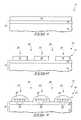
- FIGS. 1-5illustrate a portion of a semiconductor construction at various process stages of an example embodiment.
- FIGS. 6-8illustrate the portion of the semiconductor construction of FIG. 2 at various process stages subsequent to FIG. 2 in accordance with another example embodiment.
- FIGS. 9-14illustrate a portion of a semiconductor construction at various process stages of another example embodiment.
- FIG. 15illustrates a portion of a semiconductor construction at a process stage subsequent to that of FIG. 2 in accordance with another example embodiment.
- FIG. 16illustrates a portion of a semiconductor construction at a process stage subsequent to that of FIG. 11 in accordance with another example embodiment.
- Some embodimentsinclude methods in which material is provided over a substrate and patterned into a first masking pattern. Subsequently, the material is treated to form repeating segments within the material, and then one or more of the segments is selectively removed to form a second masking pattern superimposed within the first masking pattern. Example embodiments are described with reference to FIGS. 1-16 .
- the construction 10includes a semiconductor substrate 12 and a material 18 formed over the substrate.
- Substrate 12comprises a base 14 , and a material 16 supported over the base.
- semiconductor substrateand “semiconductor substrate” mean any construction comprising semiconductive material, including, but not limited to, bulk semiconductive materials such as a semiconductive wafer (either alone or in assemblies comprising other materials thereon), and semiconductive material layers (either alone or in assemblies comprising other materials).
- substraterefers to any supporting structure, including, but not limited to, the semiconductive substrates described above.
- Base 14may correspond to a semiconductor material, and in some embodiments may correspond to a monocrystalline silicon wafer.
- Material 16represents a material which is to be patterned during fabrication of integrated circuitry.
- Material 16may be an electrically insulative material (for instance, may comprise one or more of silicon nitride, silicon dioxide, etc.), an electrically conductive material (for instance, may comprise one or more of various metals, metal-containing compositions, conductively-doped semiconductor material, etc.) or a semiconductive material (for instance, silicon, germanium, etc.).
- an electrically insulative materialfor instance, may comprise one or more of silicon nitride, silicon dioxide, etc.
- an electrically conductive materialfor instance, may comprise one or more of various metals, metal-containing compositions, conductively-doped semiconductor material, etc.
- a semiconductive materialfor instance, silicon, germanium, etc.
- NAND unit cellsthere may be a plurality of gate materials stacked over the base; with such gate materials ultimately being simultaneously patterned to form a plurality of gate constructions supported by the base.
- cross-point memorythere may be a plurality of materials stacked over base 14 ; with such materials ultimately being simultaneously patterned to form a plurality of lines extending across the base.
- DRAMthere may be a plurality of materials stacked over base 14 ; with such materials ultimately being simultaneously patterned to form a plurality of wordlines and/or bitlines extending across the base.
- Material 18is radiation-sensitive so that it may be patterned by photolithographic methodology, and comprises block copolymer.
- material 18may comprise a blend of block copolymer and conventional photoresist.
- material 18may comprise, consist essentially of, or consist of a material which includes both the self-assembling properties of block copolymers and the photosensitivity of photoresist materials.
- Material 18may have one or more “leaving groups”, which are either radiation-releasable and/or releasable after interaction with additional species that are radiation-releasable, (e.g. photo-acids). Such leaving groups may be referred to as leaving groups that may be released through radiation-induced cleavage.
- Copolymersare polymers derived from two or more different monomeric species.
- Block copolymerscontain two or more homopolymer subunits linked by covalent bonds. The union of the homopolymer subunits may utilize an intermediate non-repeating linkage, known as a junction block.
- the term “block copolymer”may be generic for any heterogeneous material that can micro-phase separate to form domains on sub-lithographic-length scales.
- Block copolymersmay be, for example, organic, organo-metallic, or organo-Si.
- Block copolymers with two distinct blocksmay be referred to as diblock copolymers.
- Block copolymersmay be identified by the number of distinct homopolymer subunits contained therein.
- block copolymers containing only two distinct homopolymer subunitsmay be referred to as diblock copolymers, and block copolymers containing only three distinct homopolymer subunits may be referred to as triblock copolymers.
- Example block copolymersthat may be utilized in applications in which the copolymer is dispersed in conventional photoresist are polystyrene-b-poly (2-vinylpyridine) (PS-b-P2VP); polystyrene-b-poly (ethylene-alt-propylene); polystyrene-b-poly(methylmethacrylate) (PS-b-PMMA); polystyrene-block-poly(ethylene oxide) (PS-b-PEO); and polystyrene-b-poly(dimethyl-siloxane) (PS-b-PDMS).
- PS-b-P2VPpolystyrene-b-poly (2-vinylpyridine)
- PS-b-PMMApolystyrene-b-poly(methylmethacrylate)
- PS-b-PEOpolystyrene-block-poly(ethylene oxide)
- PS-b-PDMSpolystyrene-b-poly
- Example block copolymers that may be utilized in applications in which the copolymer is utilized as a radiation-sensitive compoundare copolymers analogous to PS-b-PMMA, and comprising modified subunits that contain leaving groups that may be released through radiation-induced cleavage; with such molecules being base soluble after cleavage of the leaving groups in some embodiments.
- the modified subunitsmay be the polystyrene subunit alone, the methylmethacrylate subunit alone, or both the polystyrene subunit and the methylmethacrylate subunit.
- such modificationmay utilize poly ⁇ 4-[(tert-butoxycarbonyl)oxy]styrene ⁇ in place of the polystyrene, with the tert-butoxyl group being a leaving group that may be released through radiation-induced cleavage; and if the methylmethacrylate subunit is modified, such modification may utilize cycloolefin-polymethacrylate in place of methylmethacrylate, with the cycloolefin being a group that may be released through radiation-induced cleavage.
- block polymersare PS-b-PS modified -b-PMMA and PS-b-PMMA-b-PMMA modified ; where PS modified and PMMA modified are derivatives of polystyrene and poly(methylmethacrylate), respectively.
- Material 18may be deposited over material 16 utilizing any suitable methodology, including, for example, spin-on methodologies.
- Material 18may be treated with a so-called “soft bake” after deposition of material 18 .
- the soft bakemay be at a temperature that is near or below the glass transition temperature (Tg) of material 18 .
- the soft bakemay be at a temperature of from about 110° C. to about 120° C., while material 18 has a Tg of from about 140° C. to about 150° C.
- the soft bakemay be utilized to remove solvent that was present in material 18 as a carrier during deposition of material 18 .
- Material 18may be photolithographically patterned, and FIG. 2 shows construction 10 at a processing stage after photolithographic patterning of material 18 .
- the patterninghas formed material 18 into a patterned mask 19 .
- Patterned mask 19includes a plurality of masking features 20 , 22 and 24 , which are spaced from one another by intervening gaps 26 and 28 .
- the patterned mask of FIG. 2i.e., the mask formed by photolithographic patterning of material 18
- the photolithographic patterning of material 18comprises exposure of some regions of material 18 to electromagnetic radiation (i.e. actinic radiation), while leaving other regions unexposed; followed by utilization of a developer solution to remove either the exposed or unexposed regions, and to leave the non-removed regions as the patterned mask.
- electromagnetic radiationi.e. actinic radiation
- the exposure of some regions of material 18 to electromagnetic radiationmay be considered to be exposure of material 18 to patterned electromagnetic radiation.
- the patterned electromagnetic radiationmay be of any suitable wavelength, and may, for example, be 365 nanometer wavelength radiation, 248 nanometer wavelength radiation, 193 nanometer wavelength radiation, extreme ultraviolet (EUV) radiation, etc.
- material 18may receive a thermal treatment after the exposure to the electromagnetic radiation, and prior to the utilization of the developer.
- thermal treatmentmay be referred to as a “post exposure bake”, and may be utilized to enhance migration of chemicals (for instance acid) within chemically-amplified photoresist.
- the post exposure bakemay be conducted at a temperature of less than or equal to a glass temperature of material 18 (with the glass transition temperature being a temperature of at least about 100° C. and less than or equal to about 150° C. in some embodiments); and in some embodiments may be conducted at a temperature of from about 90° C. to about 120° C.
- the conventional photoresistmay be a chemically-amplified resist. If the addition of the block copolymer influences a rate of chemical amplification, the concentration of amplifying chemical and/or the duration of a post-exposure bake may be adjusted to compensate for such influence. For instance, the chemistry or the concentration of a photoacid generator (PAG) may be adjusted.
- PAGphotoacid generator
- such block copolymermay be utilized in combination with chemical amplifiers (such as, for example, PAGs).
- chemical amplifierssuch as, for example, PAGs.
- the duration and temperature of the post-exposure bake and/or photoacid generator chemistry, and/or photoacid quench chemistrymay be adjusted to obtain desired amplification of the effect of the electromagnetic radiation exposure.
- the exposure to radiationmay convert the subunits of the block copolymer to polyhydroxystyrene (PHOST) and polyacrylic acid (PAA) or similar subunits that may be developed and selectively removed/left from the subunits in unexposed regions.
- PHOSTpolyhydroxystyrene
- PAApolyacrylic acid
- such conversionmay be chemically amplified with a post exposure bake.
- the specific chemistry described hereinis an example chemistry, and other embodiments may utilize other chemistries to achieve similar results.
- the exposure to the electromagnetic radiation, and the post-exposure bake(in embodiments utilizing a post-exposure bake), cause some portions of material 18 to be modified relative to other portions.
- the developer mentioned previouslyis then utilized to selectively remove either the modified portions, or the unmodified portions.
- the developermay be a conventional developer suitable for selectively dissolving either the modified or unmodified portions, and may, for example, comprise an aqueous solution of tetramethylammonium hydroxide (TMAH).
- TMAHtetramethylammonium hydroxide
- the block copolymer in exposed regionsmay be “developable” by the action of a photoacid generator, and/or the developer may be configured for selectively dissolving the block copolymer in exposed regions without extracting significant amounts of block copolymer from the unexposed regions.
- An upper surface of material 16is uncovered within gaps 26 and 28 .
- the uncovered upper surface of material 16may be coated, grafted and/or functionalized to change properties of the upper surface so that it becomes less wettable relative to material 18 . Such can impede material 18 from accumulating across gaps 26 and 28 in subsequent processing (discussed below).
- the amount of material 18 , size of gaps 26 and 28 , and parameters of the subsequent processingmay be adjusted so that material 18 does not disperse entirely across gaps 26 and 28 regardless of whether or not the upper surface of material 16 is treated. It is noted, however, that there may alternatively be some embodiments in which it is desired for material 18 to extend entirely across gaps 26 and 28 after the subsequent processing.
- the block copolymermay be a diblock copolymer, and in such embodiments may be generically represented as A-B, where the “A” represents one of the homopolymer subunits, the “B” represents the other of the homopolymer subunits, and the hyphen represents a covalent bond.
- a pattern resulting from self-assembly of diblock copolymermay be designated by the shorthand A-B:B-A:A-B:B-A; where the hyphen represents covalent interactions, and the colon represents non-covalent interactions.
- features 32may comprise the A subunits of the block copolymer
- features 34may comprise the B subunits of the block copolymer, or vice versa.
- the features 32 and 34differ from one another relative to the wetting of air and substrate interfaces, and this leads to the self-assembly of the features 32 and 34 into the pattern shown in FIG. 3 .
- FIG. 3illustrates one of many configurations that may result from self-assembly of block copolymer.
- FIG. 15shows another configuration that may result from self-assembly of the block copolymer.
- the features 32may include other components in addition to one of the subunits of the block copolymer.
- the features 32may include such other substances as well as including one of the subunits of the block copolymer.
- features 32may be considered to alternate with features 34 along a cross-section through masking blocks 20 , 22 and 24 ; and in such embodiments the features 32 and 34 along such cross-section may be considered to comprise alternating first and second segments formed from the block copolymer.
- the features 34may be considered to correspond to a second patterned mask 35 that is formed from the first patterned mask 19 . Also, a pattern of the features 34 may be referred to as a second pattern. Such second pattern may be considered to be within the first pattern corresponding to the pattern of features 20 , 22 and 24 , or to be superimposed on the first pattern corresponding to the pattern of features 20 , 22 and 24 .
- FIG. 3illustrates one of many configurations that may result from self-assembly of block copolymer.
- FIG. 15shows another configuration that may result from self-assembly of the block copolymer.
- features 34are cylinders extending into and out of the page relative to the cross-sectional views of the figures. In other embodiments the features may be lamellae, micelles, or surface-perpendicular cylinders.
- the conditions utilized to induce self-assembly of the copolymermay be thermal conditions, and may utilize a temperature greater than about the glass transition temperature of material 18 (such temperature may be from greater than 150° C. to less than or equal to about 250° C. in some embodiments).
- self-assemblymay be induced during a solvent anneal step, where the material is exposed to the partial pressure of an appropriate solvent vapor.
- the blocks 20 , 22 and 24 of the first patterned mask 19are shown to have undergone reflow during exposure to the conditions utilized to induce self-assembly of the copolymer. Such reflow has changed the shape of blocks 20 , 22 and 24 so that the individual blocks have now spread, and become dome-shaped. The spreading of the blocks has reduced the size of gaps 26 and 28 relative to the initial size present at the processing stage of FIG. 2 .
- the amount of spreading of the individual blocksmay be influenced by numerous factors, which may include one or more of the following: the composition of the blocks, the initial volume of the blocks, the initial shape of the blocks, the temperature of a treatment utilized to induce self-assembly of the block copolymer, the duration of such treatment, the type of solvent utilized if a solvent anneal is utilized to induce the self-assembly, and a drive to minimize a total area of an air interface. Additionally, the amount of spreading of individual blocks may be influenced by a composition of the surface of material 16 , and specifically by the contact angle of material 18 relative to surface 16 . In some embodiments, at least some of the surface 16 exposed within gaps 26 and 28 may be treated to render the surface non-wettable by material 18 ( FIG.
- Such treatment of surface 16may include, for example, exposure of the surface to one or more fluoroalkyl silanes and/or silicones; and may be conducted before or after formation of blocks 20 , 22 and 24 over surface 16 .
- the gaps 26 and 28are closed as material 18 ( FIG. 2 ) reflows during the self-assembly anneal to form the second mask 35 , and the features 34 are then formed to be uniformly periodic across the entire surface 16 .
- features 34may be referred to as grapho-epitaxial alignment, and may form the features 34 to a pitch that is substantially smaller than a minimum pitch achievable by photolithographic exposure. For instance, features 34 may be formed to a pitch that is less than or equal to one-half of the minimum pitch achievable by the photolithographic process utilized to form the blocks 20 , 22 and 24 of FIG. 2 .
- most of the features 32are selectively removed relative to features 34 , to leave features 34 of patterned mask 35 remaining over material 16 .
- Some of the features 32remain beneath features 34 in the shown embodiment due to anisotropy of the etch utilized to remove features 32 .
- One method of selectively removing the shown portions of features 32 relative to features 34is to first selectively modify features 34 relative to features 32 by oxidizing or metalizing the features 34 (i.e., incorporating oxygen or metal into features 34 ), and to subsequently remove portions of features 32 by ashing with O 2 plasma. If the embodiment of FIG. 15 were utilized instead of that of FIG. 3 , a punch-through etch may be conducted to remove at least part of the outer skin (which one of the features 34 in the FIG. 15 embodiment) and thereby expose features 32 for subsequent removal.
- the patterned mask 35may be utilized to fabricate a pattern within material 16 .
- material 16may be representative of one or more materials utilized for fabrication of memory architecture (e.g., NAND, DRAM and/or cross-point memory).
- the transfer of a pattern into material 16may represent patterning of one or more materials into structures of memory architecture.
- the features 34may be used to define locations of integrated circuit components within substrate 12 .
- patterning of material 16may represent patterning of one or more gate materials of NAND unit cells; may represent patterning of a plurality of lines of cross-point memory cells; and/or may represent patterning of wordlines and/or bitlines of DRAM.
- features 32 and 34 of FIG. 5may be removed in subsequent processing; and in other embodiments, features 32 and 34 may be left to become incorporated into an integrated circuit construction.
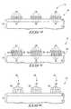
- FIG. 6shows construction 10 at a processing stage subsequent to that of FIG. 2 in accordance with an embodiment in which the self-assembly of block copolymer has formed lamella rather than cylinders. Accordingly, the material 18 of FIG. 2 has assembled into alternating segments of features 32 and 34 .
- the features 32 and 34may correspond to the A subunit of a diblock copolymer, and to the B subunit of the diblock copolymer, respectively.
- the construction of FIG. 6may be induced by any suitable method, including, for example, changing the volume fractions of the A and B subunits relative to the volume fractions that would form the construction of FIG. 3 .
- the shown lamellaemay form if the surfaces of material 16 that are covered by blocks 22 , 24 and 26 are neutral relative to wettability by features 32 and 34 (i.e., if features 32 and 34 both wet the surfaces to a comparable amount), and if features 32 are preferentially formed along an air interface relative to features 34 .
- composition 18 of FIG. 2consists of diblock material
- the structure of FIG. 6may result from induction of self-assembly of the diblock copolymer.
- masking blocks 20 , 22 and 24are converted into structures in which only repeating segments formed from the self-assembly are present after the self-assembly.
- the blocks 20 , 22 and 24 at the processing stage of FIG. 6may comprise other components in addition to the segments formed from self-assembly of the diblock copolymer.
- the blocks 20 , 22 and 24 at the processing stage of FIG. 6are illustrated to be less dome-shaped and less spread than analogous blocks at the processing stage of FIG. 3 .
- Such difference between FIGS. 3 and 6is provided to illustrate that the amount of spreading of blocks 20 , 22 and 24 that occurs during inducement of self-assembly of block copolymer may be adjusted by adjusting one or more of the parameters discussed above with reference to FIG.3 .
- one of the two types of features 32 and 34 of FIG. 6may be selectively removed relative to the other. If features 34 are to be selectively removed, there can be an etch partially into features 32 to expose features 34 for subsequent removal.
- FIG. 7shows construction 10 after the features 32 have been selectively removed relative to the features 34 .
- the remaining features 34form a patterned mask of upwardly projecting structures over material 16 .
- FIG. 8shows construction 10 after the pattern of the patterned mask of FIG. 7 has been transferred into material 16 with one or more suitable etches.
- FIGS. 1-8illustrate embodiments in which photolithographic processing is utilized to form a first pattern within a photosensitive material comprising block copolymer, and then self-assembly of the block copolymer is utilized to form a second pattern superimposed on the first pattern.
- Other methods besides photolithographymay be utilized to form the first pattern.
- FIGS. 9-12illustrate an example process in which differences of wettability of a substrate surface are utilized to induce the first pattern in a material comprising block copolymer.
- the construction 50comprises a substrate 52 .
- substrate 52may be a semiconductor substrate.
- substrate 52may be a monocrystalline silicon wafer.
- Substrate 52comprises an upper surface 53 .
- the upper surface 53may initially consist of silicon or doped silicon.
- a plurality of regions 54are illustrated, with such regions corresponding to segments of upper surface 53 that have been changed in composition relative to the remainder of upper surface 53 . Such change in composition will alter wettability of a block copolymer-containing material that is to be subsequently formed over substrate 52 .
- the treatment of the upper surfacemay comprise subjecting the upper surface to one or more fluoroalkyl silanes and/or silanols.
- regions 54may correspond to portions of the upper surface that have been exposed to perfluoroalkyl silane. Photoresist may be utilized to protect portions of surface 53 which are not to be altered during the treatment that is utilized to form the alterations that lead to regions 54 .
- the regions of upper surface 53 that have not been treatedmay be referred to as first regions 51 of the upper surface, and the treated regions 54 may be referred to as second regions of the upper surface.
- material 60is deposited over substrate 52 ( FIG. 10 ); and the material then redistributes to not be over the regions 54 of the surface of substrate 52 , and to accumulate (or bead) over the regions 51 of the surface ( FIG. 11 ).
- Material 60comprises block copolymer, and in some embodiments consists of block copolymer dispersed in a carrier solvent.
- the block copolymermay comprise any suitable block copolymer, and in some embodiments is a diblock copolymer consisting of either polystyrene-block-vinylpyridine or polystyrene-block-ethylene oxide.
- the block copolymerdisperses from regions 54 along the upper surface of material 52 , and beads over regions 51 along such upper surface, due to the differences in wettability of material 60 relative to regions 51 and 54 .
- regions 51may be configured to be wettable by material 60
- regions 54are configured to be non-wettable, and such may cause material 60 to accumulate over regions 51 while dispersing from over regions 54 .
- the material 60 of FIG. 11forms a patterned mask 62 having masking features 64 , 66 and 68 , which are spaced from one another by gaps 63 over the regions 54 .
- the pattern of the masking features 64 , 66 and 68 of the patterned mask 62may be referred to as a first pattern.
- Material 60may be deposited by any suitable method, including, for example, spin-casting.
- the patterned mask 62may be subjected to a low-temperature bake (i.e., a bake at a temperature of less than about the glass transition temperature of material 60 , which may be less than or equal to 150° C. in some embodiments) to remove carrier solvent; and in other embodiments such bake may be omitted.
- the low-temperature bakemay induce the dewetting from regions 54 .
- patterned mask 62is subjected to conditions which induce self-assembly of the block copolymer therein.
- the self-assembly within the block copolymeris shown converting material 60 into features 70 and 72 .
- Features 70are in the form of cylinders extending into and out of the page relative to the cross-sectional view of FIG. 12 .
- Feature 72is over and between the features 70 .
- features 70may be considered to alternate with features 72 along the a cross-section through masking blocks 64 , 66 and 68 ; and in such embodiments the features 70 and 72 along such cross-section may be considered to comprise alternating first and second segments formed from the block copolymer.
- solvent treatment and thermal treatmente.g., baking
- the features 70may be considered to correspond to a second patterned mask 74 that is formed from the first patterned mask 62 . Also, a pattern of the features 70 may be referred to as a second pattern, and such second pattern may be considered to be superimposed on the first pattern corresponding to the pattern of features 64 , 66 and 68 .
- features 70are cylinders in the shown embodiment, in other embodiments the features may have other shapes.
- the featuresmay be lamellar.
- the construction of FIG. 12may comprise alternating segments of features 70 and 72 analogous to the alternating segments 32 and 34 shown in FIG. 6 .
- FIG. 12illustrates one of many configurations that may result from self-assembly of block copolymer.
- FIG. 16shows another configuration that may result from self-assembly of the block copolymer.
- most of the features 72are selectively removed relative to features 70 , to leave features 70 of patterned mask 74 remaining over substrate 52 .
- portions of the features 72remain under the features 70 due to anisotropy of the etch utilized to remove features 72 .
- One method of selectively removing the shown portions of features 72 relative to features 70is to first selectively modify features 70 relative to features 72 by oxidizing or metalizing the features 70 (i.e., incorporating oxygen or metal into features 70 ), and to subsequently remove portions of features 72 by ashing with O 2 plasma.
- the patterned mask 74has been utilized to fabricate a pattern within substrate 52 .
- substrate 52may be utilized for fabrication of memory architecture (e.g., NAND, DRAM and/or cross-point memory).
- the transfer of a pattern into substrate 52may represent patterning of one or more materials into structures of memory architecture.
- the features 70may be used to define locations of integrated circuit components within substrate 52 .
- patterning of the substratemay represent patterning of one or more gate materials of NAND unit cells; may represent patterning of a plurality of lines of cross-point memory cells; and/or may represent patterning of wordlines and/or bitlines of DRAM.
- features 70 and/or modified regions 54may be removed in subsequent processing; and in other embodiments, features 70 and/or modified regions 54 may be left to become incorporated into an integrated circuit construction.
- FIGS. 1-16induce self-assembly of block copolymer to form masking features that extend horizontally across a substrate surface (specifically, the features 34 of FIG. 4 , the features 34 of FIG. 7 , and the features 70 of FIG. 13 ).
- self-assembly of block copolymermay form structures that extend vertically (i.e., project primarily upwardly) relative to a substrate surface. Such vertical structures may be utilized for various applications in semiconductor fabrication, including, for example, fabrication of contact openings to wiring or other electrically conductive structures.
Landscapes
- Engineering & Computer Science (AREA)
- Manufacturing & Machinery (AREA)
- Microelectronics & Electronic Packaging (AREA)
- General Physics & Mathematics (AREA)
- Physics & Mathematics (AREA)
- Condensed Matter Physics & Semiconductors (AREA)
- Computer Hardware Design (AREA)
- Power Engineering (AREA)
- Chemical & Material Sciences (AREA)
- Inorganic Chemistry (AREA)
- Nanotechnology (AREA)
- Analytical Chemistry (AREA)
- Exposure Of Semiconductors, Excluding Electron Or Ion Beam Exposure (AREA)
- Photosensitive Polymer And Photoresist Processing (AREA)
- Semiconductor Memories (AREA)
Abstract
Description
Claims (15)
Priority Applications (4)
| Application Number | Priority Date | Filing Date | Title |
|---|---|---|---|
| US12/248,219US8088551B2 (en) | 2008-10-09 | 2008-10-09 | Methods of utilizing block copolymer to form patterns |
| PCT/US2009/056504WO2010042290A2 (en) | 2008-10-09 | 2009-09-10 | Methods of utilizing block copolymer to form patterns |
| TW098132347ATWI426544B (en) | 2008-10-09 | 2009-09-24 | Methods of utilizing block copolymer to form patterns |
| US13/309,442US8394579B2 (en) | 2008-10-09 | 2011-12-01 | Methods of forming patterns |
Applications Claiming Priority (1)
| Application Number | Priority Date | Filing Date | Title |
|---|---|---|---|
| US12/248,219US8088551B2 (en) | 2008-10-09 | 2008-10-09 | Methods of utilizing block copolymer to form patterns |
Related Child Applications (1)
| Application Number | Title | Priority Date | Filing Date |
|---|---|---|---|
| US13/309,442ContinuationUS8394579B2 (en) | 2008-10-09 | 2011-12-01 | Methods of forming patterns |
Publications (2)
| Publication Number | Publication Date |
|---|---|
| US20100092873A1 US20100092873A1 (en) | 2010-04-15 |
| US8088551B2true US8088551B2 (en) | 2012-01-03 |
Family
ID=42099153
Family Applications (2)
| Application Number | Title | Priority Date | Filing Date |
|---|---|---|---|
| US12/248,219Active2030-06-21US8088551B2 (en) | 2008-10-09 | 2008-10-09 | Methods of utilizing block copolymer to form patterns |
| US13/309,442ActiveUS8394579B2 (en) | 2008-10-09 | 2011-12-01 | Methods of forming patterns |
Family Applications After (1)
| Application Number | Title | Priority Date | Filing Date |
|---|---|---|---|
| US13/309,442ActiveUS8394579B2 (en) | 2008-10-09 | 2011-12-01 | Methods of forming patterns |
Country Status (3)
| Country | Link |
|---|---|
| US (2) | US8088551B2 (en) |
| TW (1) | TWI426544B (en) |
| WO (1) | WO2010042290A2 (en) |
Cited By (4)
| Publication number | Priority date | Publication date | Assignee | Title |
|---|---|---|---|---|
| US20120077127A1 (en)* | 2008-10-09 | 2012-03-29 | Micron Technology, Inc. | Methods Of Forming Patterns |
| US8715917B2 (en) | 2012-10-04 | 2014-05-06 | International Business Machines Corporation | Simultaneous photoresist development and neutral polymer layer formation |
| US9107291B2 (en) | 2012-11-21 | 2015-08-11 | International Business Machines Corporation | Formation of a composite pattern including a periodic pattern self-aligned to a prepattern |
| US9738765B2 (en) | 2015-02-19 | 2017-08-22 | International Business Machines Corporation | Hybrid topographical and chemical pre-patterns for directed self-assembly of block copolymers |
Families Citing this family (44)
| Publication number | Priority date | Publication date | Assignee | Title |
|---|---|---|---|---|
| US8993221B2 (en)* | 2012-02-10 | 2015-03-31 | Pixelligent Technologies, Llc | Block co-polymer photoresist |
| US8394483B2 (en) | 2007-01-24 | 2013-03-12 | Micron Technology, Inc. | Two-dimensional arrays of holes with sub-lithographic diameters formed by block copolymer self-assembly |
| US8083953B2 (en) | 2007-03-06 | 2011-12-27 | Micron Technology, Inc. | Registered structure formation via the application of directed thermal energy to diblock copolymer films |
| US8557128B2 (en) | 2007-03-22 | 2013-10-15 | Micron Technology, Inc. | Sub-10 nm line features via rapid graphoepitaxial self-assembly of amphiphilic monolayers |
| US7959975B2 (en) | 2007-04-18 | 2011-06-14 | Micron Technology, Inc. | Methods of patterning a substrate |
| US8097175B2 (en) | 2008-10-28 | 2012-01-17 | Micron Technology, Inc. | Method for selectively permeating a self-assembled block copolymer, method for forming metal oxide structures, method for forming a metal oxide pattern, and method for patterning a semiconductor structure |
| US8294139B2 (en) | 2007-06-21 | 2012-10-23 | Micron Technology, Inc. | Multilayer antireflection coatings, structures and devices including the same and methods of making the same |
| US8372295B2 (en) | 2007-04-20 | 2013-02-12 | Micron Technology, Inc. | Extensions of self-assembled structures to increased dimensions via a “bootstrap” self-templating method |
| US8404124B2 (en)* | 2007-06-12 | 2013-03-26 | Micron Technology, Inc. | Alternating self-assembling morphologies of diblock copolymers controlled by variations in surfaces |
| US8080615B2 (en) | 2007-06-19 | 2011-12-20 | Micron Technology, Inc. | Crosslinkable graft polymer non-preferentially wetted by polystyrene and polyethylene oxide |
| KR101291223B1 (en) | 2007-08-09 | 2013-07-31 | 한국과학기술원 | Method of forming fine pattern using block copolymer |
| US8999492B2 (en) | 2008-02-05 | 2015-04-07 | Micron Technology, Inc. | Method to produce nanometer-sized features with directed assembly of block copolymers |
| US8101261B2 (en) | 2008-02-13 | 2012-01-24 | Micron Technology, Inc. | One-dimensional arrays of block copolymer cylinders and applications thereof |
| US8426313B2 (en) | 2008-03-21 | 2013-04-23 | Micron Technology, Inc. | Thermal anneal of block copolymer films with top interface constrained to wet both blocks with equal preference |
| US8425982B2 (en) | 2008-03-21 | 2013-04-23 | Micron Technology, Inc. | Methods of improving long range order in self-assembly of block copolymer films with ionic liquids |
| US8114300B2 (en) | 2008-04-21 | 2012-02-14 | Micron Technology, Inc. | Multi-layer method for formation of registered arrays of cylindrical pores in polymer films |
| US8114301B2 (en) | 2008-05-02 | 2012-02-14 | Micron Technology, Inc. | Graphoepitaxial self-assembly of arrays of downward facing half-cylinders |
| US9487600B2 (en) | 2010-08-17 | 2016-11-08 | Uchicago Argonne, Llc | Ordered nanoscale domains by infiltration of block copolymers |
| US8304493B2 (en) | 2010-08-20 | 2012-11-06 | Micron Technology, Inc. | Methods of forming block copolymers |
| US8980418B2 (en) | 2011-03-24 | 2015-03-17 | Uchicago Argonne, Llc | Sequential infiltration synthesis for advanced lithography |
| US9684234B2 (en)* | 2011-03-24 | 2017-06-20 | Uchicago Argonne, Llc | Sequential infiltration synthesis for enhancing multiple-patterning lithography |
| NL2008951A (en)* | 2011-06-23 | 2013-01-02 | Asml Netherlands Bv | Self -assemblable polymer and methods for use in lithography. |
| NL2008952A (en) | 2011-06-23 | 2013-01-02 | Asml Netherlands Bv | Self-assemblable polymer and method for use in lithography. |
| US8900963B2 (en) | 2011-11-02 | 2014-12-02 | Micron Technology, Inc. | Methods of forming semiconductor device structures, and related structures |
| US20130200498A1 (en)* | 2012-02-03 | 2013-08-08 | Applied Materials, Inc. | Methods and apparatus for lithography using a resist array |
| US9005877B2 (en)* | 2012-05-15 | 2015-04-14 | Tokyo Electron Limited | Method of forming patterns using block copolymers and articles thereof |
| JP6031420B2 (en) | 2012-08-31 | 2016-11-24 | ダウ グローバル テクノロジーズ エルエルシー | Polymer containing terminal group containing photoacid generator, photoresist containing said polymer and device manufacturing method |
| JP5937549B2 (en) | 2012-08-31 | 2016-06-22 | ダウ グローバル テクノロジーズ エルエルシー | Photoacid generator compound, polymer containing terminal group containing photoacid generator compound, and production method |
| US9087699B2 (en) | 2012-10-05 | 2015-07-21 | Micron Technology, Inc. | Methods of forming an array of openings in a substrate, and related methods of forming a semiconductor device structure |
| US8980538B2 (en) | 2013-03-14 | 2015-03-17 | Tokyo Electron Limited | Chemi-epitaxy in directed self-assembly applications using photo-decomposable agents |
| US20140273534A1 (en) | 2013-03-14 | 2014-09-18 | Tokyo Electron Limited | Integration of absorption based heating bake methods into a photolithography track system |
| US9147574B2 (en) | 2013-03-14 | 2015-09-29 | Tokyo Electron Limited | Topography minimization of neutral layer overcoats in directed self-assembly applications |
| US8975009B2 (en) | 2013-03-14 | 2015-03-10 | Tokyo Electron Limited | Track processing to remove organic films in directed self-assembly chemo-epitaxy applications |
| US9136110B2 (en)* | 2013-03-15 | 2015-09-15 | Tokyo Electron Limited | Multi-step bake apparatus and method for directed self-assembly lithography control |
| US9229328B2 (en) | 2013-05-02 | 2016-01-05 | Micron Technology, Inc. | Methods of forming semiconductor device structures, and related semiconductor device structures |
| KR102394998B1 (en) | 2013-09-04 | 2022-05-04 | 도쿄엘렉트론가부시키가이샤 | Uv-assisted stripping of hardened photoresist to create chemical templates for directed self-assembly |
| US10014184B2 (en) | 2013-09-05 | 2018-07-03 | Applied Materials, Inc. | Methods and apparatus for forming a resist array using chemical mechanical planarization |
| US9625815B2 (en)* | 2013-09-27 | 2017-04-18 | Intel Corporation | Exposure activated chemically amplified directed self-assembly (DSA) for back end of line (BEOL) pattern cutting and plugging |
| US9177795B2 (en) | 2013-09-27 | 2015-11-03 | Micron Technology, Inc. | Methods of forming nanostructures including metal oxides |
| US9793137B2 (en) | 2013-10-20 | 2017-10-17 | Tokyo Electron Limited | Use of grapho-epitaxial directed self-assembly applications to precisely cut logic lines |
| US9349604B2 (en) | 2013-10-20 | 2016-05-24 | Tokyo Electron Limited | Use of topography to direct assembly of block copolymers in grapho-epitaxial applications |
| DE102015222782A1 (en) | 2015-11-18 | 2017-05-18 | Sirona Dental Systems Gmbh | Method for visualizing a dental situation |
| US9947597B2 (en) | 2016-03-31 | 2018-04-17 | Tokyo Electron Limited | Defectivity metrology during DSA patterning |
| US12104249B2 (en) | 2019-07-18 | 2024-10-01 | Uchicago Argonne, Llc | Sequential infiltration synthesis of group 13 oxide electronic materials |
Citations (15)
| Publication number | Priority date | Publication date | Assignee | Title |
|---|---|---|---|---|
| US5707784A (en) | 1992-09-16 | 1998-01-13 | Fujitsu Ltd. | Method of forming chemically amplified resist pattern and manufacturing for semiconductor device by using the chemically amplified resist pattern |
| US5759739A (en) | 1993-04-15 | 1998-06-02 | Shin-Etsu Chemical Co., Ltd. | Resist composition with polymeric dissolution inhibitor and alkali soluble resin |
| US20050233597A1 (en) | 2002-11-05 | 2005-10-20 | International Business Machines Corp. | Nonlithographic method to produce self-aligned mask, articles produced by same and compositions for same |
| US20060046205A1 (en) | 2004-07-22 | 2006-03-02 | Jung-Hwan Hah | Mask pattern for semiconductor device fabrication, method of forming the same, and method of fabricating finely patterned semiconductor device |
| US20070212522A1 (en) | 2005-06-10 | 2007-09-13 | Babak Heidari | Imprint stamp comprising Cyclic Olefin copolymer |
| US20080041818A1 (en) | 2006-08-15 | 2008-02-21 | Kabushiki Kaisha Toshiba | Method for pattern formation |
| US7405034B2 (en)* | 2001-08-01 | 2008-07-29 | State Of Oregon Acting By And Through The State Board Of Higher Education On Behalf Of Portland State University | Polymeric structures, particularly microstructures, and methods for making same |
| US20080193658A1 (en) | 2007-02-08 | 2008-08-14 | Micron Technology, Inc. | Methods using block copolymer self-assembly for sub-lithographic patterning |
| US20090035668A1 (en)* | 2007-07-30 | 2009-02-05 | Gregory Breyta | Method and materials for patterning a neutral surface |
| US20090042146A1 (en)* | 2007-08-09 | 2009-02-12 | Kyoung Taek Kim | Method of forming fine patterns using a block copolymer |
| US20090087664A1 (en)* | 2005-10-14 | 2009-04-02 | Wisconsin Alumni Research Foundation | Directed assembly of triblock copolymers |
| WO2009056504A1 (en) | 2007-10-31 | 2009-05-07 | Icera Inc | Processing signals in a wireless network |
| US20090155725A1 (en)* | 2007-12-14 | 2009-06-18 | Shi-Yong Yi | Method of fine patterning semiconductor device |
| US7560141B1 (en)* | 2008-11-11 | 2009-07-14 | International Business Machines Corporation | Method of positioning patterns from block copolymer self-assembly |
| US7651735B2 (en)* | 2007-03-23 | 2010-01-26 | International Business Machines Corporation | Orienting, positioning, and forming nanoscale structures |
Family Cites Families (2)
| Publication number | Priority date | Publication date | Assignee | Title |
|---|---|---|---|---|
| US6746825B2 (en)* | 2001-10-05 | 2004-06-08 | Wisconsin Alumni Research Foundation | Guided self-assembly of block copolymer films on interferometrically nanopatterned substrates |
| US8088551B2 (en)* | 2008-10-09 | 2012-01-03 | Micron Technology, Inc. | Methods of utilizing block copolymer to form patterns |
- 2008
- 2008-10-09USUS12/248,219patent/US8088551B2/enactiveActive
- 2009
- 2009-09-10WOPCT/US2009/056504patent/WO2010042290A2/enactiveApplication Filing
- 2009-09-24TWTW098132347Apatent/TWI426544B/enactive
- 2011
- 2011-12-01USUS13/309,442patent/US8394579B2/enactiveActive
Patent Citations (16)
| Publication number | Priority date | Publication date | Assignee | Title |
|---|---|---|---|---|
| US5707784A (en) | 1992-09-16 | 1998-01-13 | Fujitsu Ltd. | Method of forming chemically amplified resist pattern and manufacturing for semiconductor device by using the chemically amplified resist pattern |
| US5759739A (en) | 1993-04-15 | 1998-06-02 | Shin-Etsu Chemical Co., Ltd. | Resist composition with polymeric dissolution inhibitor and alkali soluble resin |
| US7405034B2 (en)* | 2001-08-01 | 2008-07-29 | State Of Oregon Acting By And Through The State Board Of Higher Education On Behalf Of Portland State University | Polymeric structures, particularly microstructures, and methods for making same |
| US20050233597A1 (en) | 2002-11-05 | 2005-10-20 | International Business Machines Corp. | Nonlithographic method to produce self-aligned mask, articles produced by same and compositions for same |
| US20060046205A1 (en) | 2004-07-22 | 2006-03-02 | Jung-Hwan Hah | Mask pattern for semiconductor device fabrication, method of forming the same, and method of fabricating finely patterned semiconductor device |
| US20070212522A1 (en) | 2005-06-10 | 2007-09-13 | Babak Heidari | Imprint stamp comprising Cyclic Olefin copolymer |
| US20090087664A1 (en)* | 2005-10-14 | 2009-04-02 | Wisconsin Alumni Research Foundation | Directed assembly of triblock copolymers |
| US20080041818A1 (en) | 2006-08-15 | 2008-02-21 | Kabushiki Kaisha Toshiba | Method for pattern formation |
| US20080193658A1 (en) | 2007-02-08 | 2008-08-14 | Micron Technology, Inc. | Methods using block copolymer self-assembly for sub-lithographic patterning |
| US7651735B2 (en)* | 2007-03-23 | 2010-01-26 | International Business Machines Corporation | Orienting, positioning, and forming nanoscale structures |
| US20090035668A1 (en)* | 2007-07-30 | 2009-02-05 | Gregory Breyta | Method and materials for patterning a neutral surface |
| US7790350B2 (en)* | 2007-07-30 | 2010-09-07 | International Business Machines Corporation | Method and materials for patterning a neutral surface |
| US20090042146A1 (en)* | 2007-08-09 | 2009-02-12 | Kyoung Taek Kim | Method of forming fine patterns using a block copolymer |
| WO2009056504A1 (en) | 2007-10-31 | 2009-05-07 | Icera Inc | Processing signals in a wireless network |
| US20090155725A1 (en)* | 2007-12-14 | 2009-06-18 | Shi-Yong Yi | Method of fine patterning semiconductor device |
| US7560141B1 (en)* | 2008-11-11 | 2009-07-14 | International Business Machines Corporation | Method of positioning patterns from block copolymer self-assembly |
Non-Patent Citations (11)
| Title |
|---|
| C.T. Black, et al. "Polymer self assembly in semiconductor microelectronics" IBM J. Res. & Dev., vol. 51 No. 5 Sep. 2007, pp. 605-633. |
| Erik W. Edwards, et al. "Mechanism and Kinetics of Ordering in Diblock Copolymer Thin Films on Chemically Nanopatterned Substrates" Journal of Polymer Science Part B, Polymer Physics, vol. 43, pp. 344-3459 2005 Wiley Periodicals, Inc. |
| Gabriel G. Baralia, et al. "Nanodecoding by Dewetting" Advanced Materials 2007, 19, pp. 4453-4459. |
| Kim, Yun Jun, "Synthesis of diblock copolymer containing photoacid-generator by RAFT PMSE 24" Internet Post dated Feb. 5, 2009, one page, http://oasys.acs.org/acs/237/nm/htsearch.cgi?words=Yun+Jun+Kim&action=search&formac.... |
| Kim, Yun Jun, "Synthesis of diblock copolymer containing photoacid-generator by RAFT PMSE 24" Internet Post dated Feb. 5, 2009, one page, http://oasys2.confex.com/acs/237nm/techprogram/P1249484.HTM. |
| Laurence Ressier, et al. "Control of micro- and nanopatterns of octadecyltrimethoxysilane monolayers using nanoimprint lithography and atmospheric chemical vapor deposition" J. Vac. Sci Technol. B 25(a), Jan./Feb. 2007, 2007 American Vacuum Society, pp. 17-18. |
| Li, Mingqi, et al., "Block copolymer patterns and templates" Materials Today, Sep. 2006, vol. 9, No. 9, pp. 30-39. |
| Mary E. Anderson, et al. "Combining Conventional Lithography with Molecular Self-Assembly for Chemical Patterning" Advanced Materials, 2006, 18, pp. 3258-3260. |
| Mingqi Li et al., "Spatially Controlled Fabrication of Nanoporous Block Copolymers" Chem. Mater. Apr. 22, 2004, 16, 3800-3808. |
| R.V. Martinez, et al. "Sequential and parallel patterning by local chemical nanolithography" Institute of Physics Publishing, Nanotechnology 18 (2007), 2007 IOP Publishing Ltd., pp. 1-6. |
| Sunggook Park, et al. "Chemical patterning of sub-50-nm half pitches via nanoimprint lithography" Science Direct, Micronelectronic Engineering, 2005 Elsevier B.V., pp. 682-688. |
Cited By (6)
| Publication number | Priority date | Publication date | Assignee | Title |
|---|---|---|---|---|
| US20120077127A1 (en)* | 2008-10-09 | 2012-03-29 | Micron Technology, Inc. | Methods Of Forming Patterns |
| US8394579B2 (en)* | 2008-10-09 | 2013-03-12 | Micron Technology, Inc. | Methods of forming patterns |
| US8715917B2 (en) | 2012-10-04 | 2014-05-06 | International Business Machines Corporation | Simultaneous photoresist development and neutral polymer layer formation |
| US9107291B2 (en) | 2012-11-21 | 2015-08-11 | International Business Machines Corporation | Formation of a composite pattern including a periodic pattern self-aligned to a prepattern |
| US9738765B2 (en) | 2015-02-19 | 2017-08-22 | International Business Machines Corporation | Hybrid topographical and chemical pre-patterns for directed self-assembly of block copolymers |
| US10059820B2 (en) | 2015-02-19 | 2018-08-28 | International Business Machines Corporation | Hybrid topographical and chemical pre-patterns for directed self-assembly of block copolymers |
Also Published As
| Publication number | Publication date |
|---|---|
| WO2010042290A2 (en) | 2010-04-15 |
| US8394579B2 (en) | 2013-03-12 |
| TWI426544B (en) | 2014-02-11 |
| WO2010042290A3 (en) | 2010-06-24 |
| TW201023246A (en) | 2010-06-16 |
| US20120077127A1 (en) | 2012-03-29 |
| US20100092873A1 (en) | 2010-04-15 |
Similar Documents
| Publication | Publication Date | Title |
|---|---|---|
| US8088551B2 (en) | Methods of utilizing block copolymer to form patterns | |
| US7790350B2 (en) | Method and materials for patterning a neutral surface | |
| US11538684B2 (en) | UV-assisted stripping of hardened photoresist to create chemical templates for directed self-assembly | |
| US8399174B2 (en) | Method of forming fine patterns using a block copolymer | |
| US8334089B2 (en) | Method of fine patterning semiconductor device | |
| US9285682B2 (en) | Pre-patterned hard mask for ultrafast lithographic imaging | |
| US8173034B2 (en) | Methods of utilizing block copolymer to form patterns | |
| US9107291B2 (en) | Formation of a composite pattern including a periodic pattern self-aligned to a prepattern | |
| SG185804A1 (en) | Methods of forming patterns on substrates | |
| US20150303055A1 (en) | Methods for fabricating integrated circuits including surface treating for directed self-assembly | |
| US10727078B2 (en) | Methods of forming fine patterns | |
| US9881793B2 (en) | Neutral hard mask and its application to graphoepitaxy-based directed self-assembly (DSA) patterning | |
| US9613820B1 (en) | Method of forming patterns | |
| US9563122B2 (en) | Method to harden photoresist for directed self-assembly processes | |
| US20160035565A1 (en) | Methods for fabricating integrated circuits using directed self-assembly chemoepitaxy | |
| JP2017157590A (en) | Pattern forming method | |
| US9455154B2 (en) | Methods for fabricating guide patterns and methods for fabricating integrated circuits using such guide patterns |
Legal Events
| Date | Code | Title | Description |
|---|---|---|---|
| AS | Assignment | Owner name:MICRON TECHNOLOGY, INC.,IDAHO Free format text:ASSIGNMENT OF ASSIGNORS INTEREST;ASSIGNORS:SILLS, SCOTT;MILLWARD, DAN;REEL/FRAME:021654/0543 Effective date:20081007 Owner name:MICRON TECHNOLOGY, INC., IDAHO Free format text:ASSIGNMENT OF ASSIGNORS INTEREST;ASSIGNORS:SILLS, SCOTT;MILLWARD, DAN;REEL/FRAME:021654/0543 Effective date:20081007 | |
| FEPP | Fee payment procedure | Free format text:PAYOR NUMBER ASSIGNED (ORIGINAL EVENT CODE: ASPN); ENTITY STATUS OF PATENT OWNER: LARGE ENTITY | |
| STCF | Information on status: patent grant | Free format text:PATENTED CASE | |
| CC | Certificate of correction | ||
| FPAY | Fee payment | Year of fee payment:4 | |
| AS | Assignment | Owner name:U.S. BANK NATIONAL ASSOCIATION, AS COLLATERAL AGENT, CALIFORNIA Free format text:SECURITY INTEREST;ASSIGNOR:MICRON TECHNOLOGY, INC.;REEL/FRAME:038669/0001 Effective date:20160426 Owner name:U.S. BANK NATIONAL ASSOCIATION, AS COLLATERAL AGEN Free format text:SECURITY INTEREST;ASSIGNOR:MICRON TECHNOLOGY, INC.;REEL/FRAME:038669/0001 Effective date:20160426 | |
| AS | Assignment | Owner name:MORGAN STANLEY SENIOR FUNDING, INC., AS COLLATERAL AGENT, MARYLAND Free format text:PATENT SECURITY AGREEMENT;ASSIGNOR:MICRON TECHNOLOGY, INC.;REEL/FRAME:038954/0001 Effective date:20160426 Owner name:MORGAN STANLEY SENIOR FUNDING, INC., AS COLLATERAL Free format text:PATENT SECURITY AGREEMENT;ASSIGNOR:MICRON TECHNOLOGY, INC.;REEL/FRAME:038954/0001 Effective date:20160426 | |
| AS | Assignment | Owner name:U.S. BANK NATIONAL ASSOCIATION, AS COLLATERAL AGENT, CALIFORNIA Free format text:CORRECTIVE ASSIGNMENT TO CORRECT THE REPLACE ERRONEOUSLY FILED PATENT #7358718 WITH THE CORRECT PATENT #7358178 PREVIOUSLY RECORDED ON REEL 038669 FRAME 0001. ASSIGNOR(S) HEREBY CONFIRMS THE SECURITY INTEREST;ASSIGNOR:MICRON TECHNOLOGY, INC.;REEL/FRAME:043079/0001 Effective date:20160426 Owner name:U.S. BANK NATIONAL ASSOCIATION, AS COLLATERAL AGEN Free format text:CORRECTIVE ASSIGNMENT TO CORRECT THE REPLACE ERRONEOUSLY FILED PATENT #7358718 WITH THE CORRECT PATENT #7358178 PREVIOUSLY RECORDED ON REEL 038669 FRAME 0001. ASSIGNOR(S) HEREBY CONFIRMS THE SECURITY INTEREST;ASSIGNOR:MICRON TECHNOLOGY, INC.;REEL/FRAME:043079/0001 Effective date:20160426 | |
| AS | Assignment | Owner name:JPMORGAN CHASE BANK, N.A., AS COLLATERAL AGENT, ILLINOIS Free format text:SECURITY INTEREST;ASSIGNORS:MICRON TECHNOLOGY, INC.;MICRON SEMICONDUCTOR PRODUCTS, INC.;REEL/FRAME:047540/0001 Effective date:20180703 Owner name:JPMORGAN CHASE BANK, N.A., AS COLLATERAL AGENT, IL Free format text:SECURITY INTEREST;ASSIGNORS:MICRON TECHNOLOGY, INC.;MICRON SEMICONDUCTOR PRODUCTS, INC.;REEL/FRAME:047540/0001 Effective date:20180703 | |
| AS | Assignment | Owner name:MICRON TECHNOLOGY, INC., IDAHO Free format text:RELEASE BY SECURED PARTY;ASSIGNOR:U.S. BANK NATIONAL ASSOCIATION, AS COLLATERAL AGENT;REEL/FRAME:047243/0001 Effective date:20180629 | |
| MAFP | Maintenance fee payment | Free format text:PAYMENT OF MAINTENANCE FEE, 8TH YEAR, LARGE ENTITY (ORIGINAL EVENT CODE: M1552); ENTITY STATUS OF PATENT OWNER: LARGE ENTITY Year of fee payment:8 | |
| AS | Assignment | Owner name:MICRON TECHNOLOGY, INC., IDAHO Free format text:RELEASE BY SECURED PARTY;ASSIGNOR:MORGAN STANLEY SENIOR FUNDING, INC., AS COLLATERAL AGENT;REEL/FRAME:050937/0001 Effective date:20190731 | |
| AS | Assignment | Owner name:MICRON TECHNOLOGY, INC., IDAHO Free format text:RELEASE BY SECURED PARTY;ASSIGNOR:JPMORGAN CHASE BANK, N.A., AS COLLATERAL AGENT;REEL/FRAME:051028/0001 Effective date:20190731 Owner name:MICRON SEMICONDUCTOR PRODUCTS, INC., IDAHO Free format text:RELEASE BY SECURED PARTY;ASSIGNOR:JPMORGAN CHASE BANK, N.A., AS COLLATERAL AGENT;REEL/FRAME:051028/0001 Effective date:20190731 | |
| MAFP | Maintenance fee payment | Free format text:PAYMENT OF MAINTENANCE FEE, 12TH YEAR, LARGE ENTITY (ORIGINAL EVENT CODE: M1553); ENTITY STATUS OF PATENT OWNER: LARGE ENTITY Year of fee payment:12 |