US8088067B2 - Tissue aberration corrections in ultrasound therapy - Google Patents
Tissue aberration corrections in ultrasound therapyDownload PDFInfo
- Publication number
- US8088067B2 US8088067B2US10/328,584US32858402AUS8088067B2US 8088067 B2US8088067 B2US 8088067B2US 32858402 AUS32858402 AUS 32858402AUS 8088067 B2US8088067 B2US 8088067B2
- Authority
- US
- United States
- Prior art keywords
- tissue
- target site
- correction factors
- transducer
- acoustic energy
- Prior art date
- Legal status (The legal status is an assumption and is not a legal conclusion. Google has not performed a legal analysis and makes no representation as to the accuracy of the status listed.)
- Active, expires
Links
- 238000012937correctionMethods0.000titleclaimsabstractdescription86
- 238000002604ultrasonographyMethods0.000titleclaimsdescription25
- 238000002560therapeutic procedureMethods0.000titleclaimsdescription9
- 230000004075alterationEffects0.000titledescription7
- 230000005284excitationEffects0.000claimsabstractdescription52
- 238000003384imaging methodMethods0.000claimsabstractdescription6
- 210000001519tissueAnatomy0.000claimsdescription278
- 238000000034methodMethods0.000claimsdescription59
- 230000010363phase shiftEffects0.000claimsdescription39
- 238000009877renderingMethods0.000claimsdescription34
- 210000000988bone and boneAnatomy0.000claimsdescription28
- 238000002591computed tomographyMethods0.000claimsdescription13
- 238000004364calculation methodMethods0.000claimsdescription11
- 210000004556brainAnatomy0.000claimsdescription9
- 230000001934delayEffects0.000claimsdescription3
- 238000006073displacement reactionMethods0.000claimsdescription3
- 210000003625skullAnatomy0.000description74
- 239000010410layerSubstances0.000description34
- 238000011282treatmentMethods0.000description17
- 210000003205muscleAnatomy0.000description12
- 210000005013brain tissueAnatomy0.000description11
- 210000004872soft tissueAnatomy0.000description10
- 230000005540biological transmissionEffects0.000description8
- 239000013598vectorSubstances0.000description8
- 206010028980NeoplasmDiseases0.000description6
- 230000008859changeEffects0.000description6
- 230000006870functionEffects0.000description6
- 230000008569processEffects0.000description6
- 238000002679ablationMethods0.000description5
- 238000004458analytical methodMethods0.000description5
- 230000001054cortical effectEffects0.000description5
- 239000000463materialSubstances0.000description5
- 239000002356single layerSubstances0.000description5
- 238000012546transferMethods0.000description5
- 210000000056organAnatomy0.000description4
- 230000011218segmentationEffects0.000description4
- 241001269524DuraSpecies0.000description3
- 230000001276controlling effectEffects0.000description3
- 230000002596correlated effectEffects0.000description3
- 230000008878couplingEffects0.000description3
- 238000010168coupling processMethods0.000description3
- 238000005859coupling reactionMethods0.000description3
- 230000006872improvementEffects0.000description3
- 239000007788liquidSubstances0.000description3
- 238000012552reviewMethods0.000description3
- 238000012285ultrasound imagingMethods0.000description3
- XLYOFNOQVPJJNP-UHFFFAOYSA-NwaterSubstancesOXLYOFNOQVPJJNP-UHFFFAOYSA-N0.000description3
- 230000037182bone densityEffects0.000description2
- 230000003247decreasing effectEffects0.000description2
- 238000010586diagramMethods0.000description2
- 210000003734kidneyAnatomy0.000description2
- 210000004185liverAnatomy0.000description2
- 238000002595magnetic resonance imagingMethods0.000description2
- 238000005259measurementMethods0.000description2
- 239000000523sampleSubstances0.000description2
- 230000001225therapeutic effectEffects0.000description2
- 238000010521absorption reactionMethods0.000description1
- 238000013459approachMethods0.000description1
- 238000003491arrayMethods0.000description1
- 230000008499blood brain barrier functionEffects0.000description1
- 210000001218blood-brain barrierAnatomy0.000description1
- 201000011510cancerDiseases0.000description1
- 239000000919ceramicSubstances0.000description1
- 238000005352clarificationMethods0.000description1
- 239000002131composite materialSubstances0.000description1
- 230000000875corresponding effectEffects0.000description1
- 238000013461designMethods0.000description1
- 230000001066destructive effectEffects0.000description1
- 230000000694effectsEffects0.000description1
- 238000011156evaluationMethods0.000description1
- 238000012804iterative processMethods0.000description1
- 238000012544monitoring processMethods0.000description1
- 230000017074necrotic cell deathEffects0.000description1
- 230000007658neurological functionEffects0.000description1
- 229920002379silicone rubberPolymers0.000description1
- 239000004945silicone rubberSubstances0.000description1
- 238000007920subcutaneous administrationMethods0.000description1
- 238000001356surgical procedureMethods0.000description1
- 230000001131transforming effectEffects0.000description1
Images


Classifications
- A—HUMAN NECESSITIES
- A61—MEDICAL OR VETERINARY SCIENCE; HYGIENE
- A61N—ELECTROTHERAPY; MAGNETOTHERAPY; RADIATION THERAPY; ULTRASOUND THERAPY
- A61N7/00—Ultrasound therapy
- A61N7/02—Localised ultrasound hyperthermia
- A—HUMAN NECESSITIES
- A61—MEDICAL OR VETERINARY SCIENCE; HYGIENE
- A61B—DIAGNOSIS; SURGERY; IDENTIFICATION
- A61B90/00—Instruments, implements or accessories specially adapted for surgery or diagnosis and not covered by any of the groups A61B1/00 - A61B50/00, e.g. for luxation treatment or for protecting wound edges
- A61B90/36—Image-producing devices or illumination devices not otherwise provided for
- A61B90/37—Surgical systems with images on a monitor during operation
- A61B2090/374—NMR or MRI
- A—HUMAN NECESSITIES
- A61—MEDICAL OR VETERINARY SCIENCE; HYGIENE
- A61B—DIAGNOSIS; SURGERY; IDENTIFICATION
- A61B90/00—Instruments, implements or accessories specially adapted for surgery or diagnosis and not covered by any of the groups A61B1/00 - A61B50/00, e.g. for luxation treatment or for protecting wound edges
- A61B90/36—Image-producing devices or illumination devices not otherwise provided for
- A61B90/37—Surgical systems with images on a monitor during operation
- A61B2090/376—Surgical systems with images on a monitor during operation using X-rays, e.g. fluoroscopy
- A—HUMAN NECESSITIES
- A61—MEDICAL OR VETERINARY SCIENCE; HYGIENE
- A61B—DIAGNOSIS; SURGERY; IDENTIFICATION
- A61B90/00—Instruments, implements or accessories specially adapted for surgery or diagnosis and not covered by any of the groups A61B1/00 - A61B50/00, e.g. for luxation treatment or for protecting wound edges
- A61B90/36—Image-producing devices or illumination devices not otherwise provided for
- A61B90/37—Surgical systems with images on a monitor during operation
- A61B2090/378—Surgical systems with images on a monitor during operation using ultrasound
- A—HUMAN NECESSITIES
- A61—MEDICAL OR VETERINARY SCIENCE; HYGIENE
- A61B—DIAGNOSIS; SURGERY; IDENTIFICATION
- A61B8/00—Diagnosis using ultrasonic, sonic or infrasonic waves
- A61B8/08—Clinical applications
- A61B8/0808—Clinical applications for diagnosis of the brain
- A61B8/0816—Clinical applications for diagnosis of the brain using echo-encephalography
- A—HUMAN NECESSITIES
- A61—MEDICAL OR VETERINARY SCIENCE; HYGIENE
- A61B—DIAGNOSIS; SURGERY; IDENTIFICATION
- A61B8/00—Diagnosis using ultrasonic, sonic or infrasonic waves
- A61B8/08—Clinical applications
- A61B8/0858—Clinical applications involving measuring tissue layers, e.g. skin, interfaces
Definitions
- the present inventionrelates to systems and methods for performing noninvasive procedures using acoustic energy, and, more particularly, to systems and methods for focusing ultrasonic energy through inhomogeneous tissues to treat underlying tissue.
- Tissuesuch as a benign or malignant tumor
- a skull or other region of a bodymay be treated invasively, e.g., by surgically removing the tissue, or non-invasively, e.g., using thermal ablation.
- Both approachesmay effectively treat certain localized conditions within the brain, but involve delicate procedures in which it is desired to avoid destroying or damaging otherwise healthy tissue.
- These treatmentsmay not be appropriate for conditions in which diseased tissue is integrated into healthy tissue, unless destroying the healthy tissue is unlikely to affect neurological function significantly.
- Thermal ablationas may be accomplished using focused ultrasound, has particular appeal for treating tissue within the brain and other tissue regions deep within the body, because it generally does not disturb intervening or surrounding healthy tissue. Focused ultrasound may also be attractive, because acoustic energy generally penetrates well through soft tissues, and ultrasonic energy, in particular, may be focused towards focal zones having a cross-section of only a few millimeters due to relatively short wavelengths (e.g., as small as 1.5 millimeters (mm) in cross-section at one Megahertz (1 MHz)). Thus, ultrasonic energy may be focused at a region deep within the body, such as a cancerous tumor or other diseased tissue, to ablate the diseased tissue without significantly damaging surrounding healthy tissue.
- a region deep within the bodysuch as a cancerous tumor or other diseased tissue
- a piezoelectric transducermay be used that includes a plurality of transducer elements.
- a controllermay provide drive signals to each of the transducer elements, thereby causing the transducer elements to transmit acoustic energy such that constructive interference occurs at a “focal zone.”
- sufficient acoustic energymay be delivered to heat tissue within the focal zone until tissue necrosis occurs, i.e., until the tissue is destroyed.
- tissue along the path through which the acoustic energy passes (“the pass zone”) outside the focal zoneis heated only minimally, if at all, thereby minimizing damaging tissue outside the focal zone.
- the acoustic energymay interact with the tissue through multiple processes: propagation, scattering, absorption, reflection, and refraction.
- the intensity of the acoustic energy transmitted by the transducer arraygenerally determines the therapeutic effectiveness, i.e., the volume of tissue destroyed within the focal zone (although there may be some losses as the acoustic energy interacts with intervening tissue between the transducer and the focal zone).
- the size of the focus zonemay also depend upon system parameters, such as transducer element characteristics, frequency of the acoustic energy, and focal depth (the distance from the transducer to the focal zone), as well as patient-related parameters, such as tissue inhomogeneity.
- the relative phase of drive signals delivered to each transducer elementmay be adjusted based upon the distance of the respective transducer element from the focal zone.
- an average speed of soundis used to approximate the speed at which the acoustic energy passes through tissue, e.g., 1540 meters per second (m/s), and to predict the location of the focal zone.
- tissue homogeneitymay vary significantly from patient to patient, and even between different tissue regions within the same patient. Tissue inhomogeneity may decrease intensity of the acoustic energy at the focal zone and may even move the location of the focal zone within the patient's body. Specifically, because the speed of sound differs in different types of tissue, as portions of a beam of acoustic energy travel along different paths towards the focal zone, they may experience a relative phase shift or time delay, which may change the intensity at the focal zone and/or move the location of the focal zone.
- the speed of sound through fatis approximately 1460 meters per second (m/s)
- the speed of sound through muscleis approximately 1600 meters per second (m/s).
- the speed of sound through bone tissueis much faster, for example, approximately 3000 meters per second (m/s) for skull bone tissue.
- the speed of soundalso varies in different organs.
- the speed of sound in brain tissueis approximately 1570 meters per second (m/s), approximately 1555 meters per second (m/s) in the liver, and approximately 1565 meters per second (m/s) in the kidney.
- a beam of acoustic energyhas a relatively wide aperture where it enters the body, different parts of the acoustic energy may pass through different tissue pass zones, and therefore may pass through different tissue types.
- portions of the acoustic energymay experience different speeds of sound, which may shift the relative phases of acoustic energy transmitted from respective transducer elements.
- This phase shiftingmay decrease the constructive interference of the acoustic energy at the focal zone, which may reduce the effectiveness of the treatment, or may even move the focal zone in an unpredictable manner.
- a layer of fatthat is only seven millimeters (7 mm) thick within muscle tissue may introduce a phase shift of 180° at an ultrasonic frequency of one Megahertz (1 MHz), which would change desired constructive interference at the focal zone into destructive interference.
- Tissue inhomogeneitymay also cause refraction of acoustic energy at the boundaries of tissue regions having different speeds of sound. Refraction may decrease constructive interference, and hence, the intensity of the acoustic energy at the focal zone, particularly when the acoustic energy passes through bone. Thus, inhomogeneous tissue structures may generate beam aberrations and refractions, which may distort the focus and reduce the intensity, thus affecting treatment efficiency.
- the present inventionis directed to systems and methods for performing noninvasive procedures using acoustic energy, and, more particularly, to systems and methods for focusing ultrasonic energy through inhomogeneous tissue to treat underlying tissue.
- a systemfor delivering acoustic energy through intervening tissue into a target site within a tissue region.
- the systemmay include a transducer array including a plurality of transducer elements configured for transmitting acoustic energy, e.g., ultrasonic energy, along respective pass zones through the intervening tissue towards the target, site.
- acoustic energye.g., ultrasonic energy
- the systemmay include an imager for imaging the tissue region, the imager generating image data including tissue types of the intervening tissue.
- the imagermay be a magnetic resonance imager, a computer tomography imager, or an ultrasound imager.
- the imagermay generate one or more images including intensity data that include a relative density of respective tissue types.
- the imagermay generate a plurality of two-dimensional images including the intervening tissue, e.g., image slices, or may generate one- or three-dimensional images.
- a processoris coupled to the imager for receiving image data to determine boundaries between a plurality of tissue types within the intervening tissue and generate respective correction factors for the transducer elements to compensate for refraction occurring at the boundaries between the tissue types within the respective pass zones.
- the respective correction factorsmay compensate for variations in speed of sound of the tissue types within the respective pass zones.
- the processormay be configured for converting a plurality of two-dimensional images into one or more three-dimensional renderings including the intervening tissue.
- the processormay automatically determine the boundaries between different tissue types within the intervening tissue based upon the three-dimensional rendering(s).
- the image datamay include intensity data that may identify a relative density of respective tissue types, and the processor may be configured for analyzing the intensity data to identify regions including different tissue types. Once the regions of different tissue types are identified, the processor may be configured for automatically determining the boundaries between the identified regions of different tissue types, and generating the correction factors.
- the systemmay include a display for displaying the three-dimensional rendering(s) and/or the two-dimensional images, and a user interface for interacting with the rendering(s) and/or images to identify tissue types within the intervening tissue manually.
- the processormay be configured for automatically determining the boundaries between the plurality of tissue types based upon two-dimensional images acquired by the imager.
- the systemmay include a controller coupled to the processor and the transducer array that may be configured for receiving the correction factors from the processor and providing excitation signals to the transducer elements based upon the correction factors.
- the correction factorsmay include phase correction factors associated with respective transducer elements
- the controllermay include a phase adjuster for adjusting phases of excitation signals provided to the transducer elements based upon the phase correction factors, which is required in continuous wave mode.
- the processormay be configured to adjust transmit time of respective transducer elements which may be required in pulse transmission mode.
- the excitation factorsmay include amplitude correction factors associated with the transducer elements, and the controller may include one or more amplifiers for amplifying the excitation signals provided to the transducer elements based upon the amplitude correction factors.
- a methodfor focusing acoustic energy transmitted from a plurality of transducer elements of a transducer array through intervening tissue into a target site within a tissue region.
- the target siteis a tumor or other tissue structure within a brain
- the intervening tissuemay include skull bone tissue, skin, and/or dura matter.
- the target sitemay be a tumor or other tissue structure within soft tissue, and the intervening tissue may include, bone, fat, muscle, and/or organ tissue.
- One or more imagesmay be acquired of a portion of the tissue region that includes the intervening tissue and the target site.
- the one or more imagesmay include a plurality of image slices selected from magnetic resonance images, computer tomography images, and/or ultrasound images of the tissue region.
- Boundariesmay be determined between different tissue types within the intervening tissue from the one or more images.
- one or more three-dimensional renderingsmay be volumetrically reconstructed of the tissue region from the image slices. Regions of different tissue types within the tissue region may be identified based upon the three-dimensional rendering, and three-dimensional boundaries between the identified regions of different tissue types may be identified within the tissue region. This process may be performed automatically by a processor or controller, manually by an operator, or by a combination of manual and automatic procedures.
- the images of the tissue regionmay include intensity data that identify a relative density of different tissue types.
- the intensity datamay be analyzed directly to identify regions including the plurality of tissue types and/or may be reconstructed into one or more three-dimensional renderings before being analyzed. Once the tissue types are identified, the boundaries between the identified regions of different tissue types may be determined.
- Respective excitation correction factorsmay be generated for each transducer element of the transducer array to compensate for variations in speed of sound of the tissue types within pass zones extending from respective transducer elements through the intervening tissue towards the target site and/or to compensate for refraction occurring at the boundaries between the tissue types within the pass zones.
- the transducer elementsmay then be driven with excitation signals based, at least in part, upon the excitation correction factors, thereby focusing acoustic energy from the transducer array at the target site.
- the excitation correction factorsmay be generated to correct for displacement of a focal zone of the transducer away from the target site and/or to correct for defocusing of the focal zone at the target site.
- sufficient acoustic energyis focused at the target site for sufficient time to ablate tissue at the target site, as is well known in the art.
- the excitation correction factorsmay include phase shift factors
- the step of generating excitation correction factorsmay include generating the phase shift factors, at least in part, by conducting ray calculations.
- the ray calculationsmay be based upon hypothetical rays extending from each transducer element to the target site (forward ray calculations) and/or from the target site to each transducer element (reverse ray calculations).
- the excitation correction factorsmay include time delays, and the excitation correction factors may be generated by determining a respective propagation time along a pass zone extending from each transducer element through boundaries between successive tissue types and the target site.
- the propagation timemay be based, at least in part, upon the speed of sound in the successive tissue types, refraction at the boundaries between the successive tissue types, and/or a distance of a resultant path (the pass zone) between the respective transducer element and the target site.
- a methodfor focusing acoustic energy to ablate a target site within a tissue region with a transducer array comprising a plurality of transducer elements.
- One or more imagesmay be acquired of the tissue region that includes the target site and intervening tissue between the transducer array and the target site. Boundaries may be determined between a plurality of tissue types within the intervening tissue based upon the one or more images, e.g., using the systems and methods described above.
- Correction factorsmay be generated for each transducer element of the transducer array to compensate for refraction occurring at the boundaries between the tissue types within pass zones extending from respective transducer elements through the intervening tissue to the target site and for variations in speed of sound of the tissue types within the pass zones.
- the transducer elementsmay be driven with excitation signals based, at least in part, upon the correction factors to focus acoustic energy from the transducer elements at the target site for sufficient time to ablate tissue at the target site.
- the correction factorsmay include phase correction factors associated with respective transducer elements, and the phases of excitation signals provided to the respective transducer elements may be adjusted based upon the phase correction factors.
- the excitation factorsmay include amplitude correction factors associated with respective transducer elements, and the excitation signals provided to the respective transducer elements may be amplified based upon the amplitude correction factors.
- FIG. 1is a schematic diagram of an ultrasound therapy system, in accordance with the present invention.
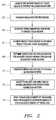
- FIG. 2is a flow diagram of a method for determining excitation correction factors and driving transducer elements using the determined factors, in accordance with the present invention.
- FIG. 3is a perspective cross-sectional view of a portion of a patient's skull.
- FIG. 4is a cross-sectional view of a patient's skull, showing representative rays of ultrasonic energy refracting as they are transmitted through the skull.
- FIG. 5is a cross sectional view of a portion of a patient's body being treated using the ultrasound therapy system of FIG. 1 .
- FIG. 6is a schematic representation of beams of acoustic energy transmitted by a transducer array and refracted by a prism-shaped tissue region.
- FIG. 7is a schematic representation of beams of acoustic energy transmitted by a transducer array and refracted by a prism-shaped tissue region with a vertex facing the transducer array.
- FIG. 1shows a preferred embodiment of a focused ultrasound system 10 , in accordance with the present invention, that includes an imager 12 , an acoustic transducer 14 , a beam former or signal adjuster 18 , a controller 20 , a frequency generator 22 , and a system image and display computer 40 .
- the system 10may also include a user interface 25 , such as a touch screen, a keyboard, and/or a mouse (not shown), and/or a display 27 .
- the system 10may determine characteristics within a skull 28 of a patient 30 and/or may deliver acoustic energy to tissue within the skull 28 , as explained further below.
- the systemis configured for delivering ultrasonic energy, e.g., between ten kilohertz (0.01 MHz) and ten Megahertz (10 MHz) to tissue within the skull 28 or other tissue region.
- the transducer 14includes a plurality of “n” transducer elements 16 (“n” being an integer greater than one), thereby providing a multiple element transducer array.
- the transducer 14may include a flexible or semi-rigid base or panel that may conform to the shape of the skull 28 .
- the transducer 14may be pre-curved (e.g. biased to a spherical or other concave shape), as shown in FIG. 1 , such that the transducer 14 may be placed on or near a portion of a skull 28 .
- the transducer 14may be planar, parabolic, or any other suitable shape, e.g., circular, elliptical, and the like.
- the transducer elements 16may be mounted to or otherwise arranged on the base of the transducer 14 in a predetermined pattern.
- the transducer elements 16may be arranged substantially symmetrically about a central axis or in an orthogonal grid pattern (not shown).
- the transducer elements 16may be mounted in silicone rubber or any other material suitable for dampening any mechanical coupling between the transducer elements 16 .
- the transducer elements 16may be one square centimeter (1 cm 2 ) piezoelectric ceramic elements. Other materials may also be used; for example, the transducer elements 16 may be formed from one or more pieces of piezocomposite material or other material that converts electrical energy to acoustic energy.
- the transducer elements 16may be configured for electrical resonance at a specific frequency or number of frequencies such that loads to amplifiers 24 i are mainly resistive.
- the transducer elements 16 of the transducer 14are electrically coupled to the signal adjuster 18 , which is, in turn, electrically coupled to the frequency generator 22 .
- the frequency generator 22may provide a common radio frequency (RF) signal as an input signal to the signal adjuster 18 .
- the frequency generator 22may be any type of generator capable of producing appropriate signals for the signal adjuster 18 .
- the frequency generator 22 and signal adjuster 18drive the individual transducer elements 16 with excitation signals such that the transducer elements 16 transmit acoustic energy.
- the excitation signals provided to each of the transducer elements 16have the same frequency, but may have different phases and/or amplitudes in order to transmit acoustic energy through the skull 28 and focus the energy at a selected region within the skull 28 , i.e., within the patient's brain (not shown).
- Signalsmay be provided to the transducer elements 16 of the transducer 14 by a driving arrangement similar to that reported in Daum et al., “Design and Evaluation of a Feedback Based Phased Array System for Ultrasound Surgery,” IEEE Trans. Ultrason. Ferroelectr. Freq. Control 45(2):431-4, 1998, the disclosure of which is expressly incorporated herein by reference, but with a driving frequency selected between about one hundred kilohertz (100 kHz) and about ten Megahertz (10 MHz).
- the power and phase to each transducer element 16may be manually controlled or automatically controlled using software and feedback.
- the signal adjuster 18includes a plurality of “n” amplifiers 24 1 - 24 N and “n” phase shifters 26 1 - 26 n , (where “n” corresponds to the number of transducer elements 16 coupled to the signal adjuster 18 ) that are coupled in respective sets of amplifiers 24 and phase shifters 26 .
- the input signal from the frequency generator 22is split such that each of the phase shifters 26 receives the signal from the frequency generator 22 .
- Each phase shifter 26 and amplifier 24 setrepresents a channel of the signal adjuster 18 that is coupled to a respective transducer element 16 .
- the phase shifters 26may adjust the phase of the incoming signal from the frequency generator 22 by respective phase shift factors ⁇ 1 - ⁇ n .
- the phase shifters 26provide approximately one degree precision (8-bit resolution), although lower phase resolution may be adequate for many applications.
- the amplifiers 24amplify the signals from the phase shifters 26 to provide amplified excitation signals to the transducer elements 16 , e.g., via coaxial cables or other connections, which may individually connect the amplifiers 24 and respective transducer elements 16 .
- individual transducer elements 16may be switched off (set to an amplitude of zero) if the pass zones of the respective transducer elements include air pockets, if the beam incidence angle is too low, or in light of other factors.
- An internal power meter (not shown) in the signal adjuster 18may monitor power supplied by the amplifiers 24 .
- phase shift factors ⁇ 1 - ⁇ n of the phase shifters 26allow the acoustic energy transmitted by the transducer elements 16 to be steered, i.e., allow the “focal zone” (the region in space towards which the acoustic energy is focused) to be moved, e.g., along a “z” axis (an axis extending orthogonally from the transmission surface of the transducer 14 into the skull 28 , not shown) and/or along the “x” or “y” axes.
- the component of each phase shift factor associated with steeringmay be computed using known techniques, e.g., using average speed of sound in the body and the distance from each transducer element 16 to a target site of interest (the intended focal zone within a tissue region).
- phase shift factorsmay also compensate for phase distortion of the ultrasonic energy transmitted by each transducer element 16 that is caused when the acoustic energy passes through tissue within the skull 28 .
- the component of each phase shift factor ⁇ 1 - ⁇ n associated with phase distortionmay compensate for perturbations and distortions introduced by the bone of the skull, the skin/skull interface, the dura matter/skull interface, by variations in skull thickness, and/or by structural considerations such as air-filled or liquid-filled pockets in the skull 28 (all not shown).
- phase shift factors ⁇ 1 - ⁇ nThe two components that make up the phase shift factors ⁇ 1 - ⁇ n , i.e., the steering components and the phase distortion components, are summed to determine the composite phase shift factors ⁇ 1 - ⁇ n for the respective channels in order to focus ultrasonic energy at a desired steering angle relative to the “z” axis and at a desired distance (“focal distance”) from the transducer 14 .
- the phase shift factors ⁇ 1 - ⁇ nare determined by the system image and display computer 40 , which may be coupled to the controller 20 and to the imager 12 .
- the controller 20itself may include all of the hardware components and/or software modules necessary to determine the phase shift factors ⁇ 1 - ⁇ n , instead of the separate computer 40 .
- the system image and display computer 40may include one or more software modules, hardware components, firmware, hardwiring, or any combinations of these.
- system image and display computer 40may be a general or special purpose digital data processor programmed with software in a conventional manner to generate the phase shift factors ⁇ 1 - ⁇ n , which may be transferred to the controller 20 for subsequent transfer to the phase shifters 26 or directly to the phase shifters 26 based upon images received from the imager 12 .
- the system image and display computer 40may determine the phase shift factors ⁇ 1 - ⁇ n by automatically analyzing images and identifying tissue characteristics of interest from the images. Sufficient information is provided by the imager 12 to the system image and display computer 40 to determine the phase shift factors ⁇ 1 - ⁇ n . Alternatively, a user may manually analyze the images and identify tissue characteristics, or a combination of automatic and manual analysis may be used.
- the imager 12may obtain images of the interior of the skull 28 from which boundaries of the skull bone tissue, and optionally other tissue regions therein, may be determined.
- the imager 12may be a Magnetic Resonance Imaging (MRI) device, a Computer Tomography (CT) device, or an Ultrasound Imaging (UIS) device (not shown).
- the imagesmay be one-dimensional images or preferably two-dimensional images of sectional planes through the site of interest. Alternatively, three-dimensional images may also be received from the imager 12 .
- the imager 12is a CT device, the imager 12 may determine and provide a CT number (also called a Hounsfield number) for each pixel in images provided by the imager 12 .
- a CT numberalso called a Hounsfield number
- the system image and display computer 40may generate a three-dimensional rendering of the skull 28 from images received from the imager 12 and determine the skull bone tissue boundaries from the three-dimensional rendering. For example, the system image and display computer 40 may divide the three-dimensional rendering into “voxels” (volume pixels of the three-dimensional image). Tissue boundaries of the imaged tissue may then be determined based upon the three-dimensional renderings, as explained below. Alternatively, the tissue boundaries may be determined and/or inferred from two-dimensional images. The images received from the imager 12 and/or the three-dimensional rendering may also be displayed on display 27 for review and/or analysis by a physician, technician, or other operator.
- FIG. 2an exemplary procedure for analyzing images of a tissue region to be treated is shown, e.g., to control delivering therapeutic energy to a target site within the tissue region.
- the methodis used in conjunction with focused ultrasound therapy, i.e., involving a multiple element transducer array that is placed adjacent the tissue region and used to deliver acoustic energy into the tissue region to the target site.
- the tissue regionis a patient's skull
- the target siteis a tumor or other tissue structure within the patient's brain.
- an imagermay acquire one or more images of the target region, e.g., the interior of the patient's skull.
- the imagermay be any of a variety of imaging devices, such as an MRI device, a CT device, or an ULS device.
- the imagesare at least one-dimensional, e.g., a plurality of vectors, and preferably are two-dimensional, e.g., a plurality of spaced-apart image planes or “slices” through the tissue region of interest.
- the tissue regionmay be a skull, and the images may be multiple slices through the skull that may be used to identify a tumor or other tissue structure within the patient's brain.
- image data representing the imagesare transferred to a processor, such as the system image and display computer 40 shown in FIG. 1 .
- the imager 12 and the system image and display computer 40may be directly coupled to one another, i.e., may be at the same location.
- the imager 12(and consequently the patient 30 ) may be at one location, and the image data from the imager 12 may be transferred to a remote system image and display computer 40 , which may receive data from multiple imagers (not shown).
- Such transfermay be over any wire or wireless network, such as a telephonic network or the Internet.
- a central system image and display computer 40may exchange data with multiple remote sites, e.g., hospitals or other treatment facilities.
- the transfer of image datamay occur immediately upon acquiring the images from the patient, for example, if the patient is undergoing treatment.
- the image datamay be stored at the imager location, e.g., in memory or on a compact disc (CD) or other portable storage device.
- a set of reference imagesmay be obtained of the tissue region at some time before performing the treatment.
- the transfermay be completed automatically or may occur only upon instruction from a physician or other operator.
- the image datamay be manipulated to generate one or more three-dimensional renderings and/or to generate treatment parameters.
- a three-dimensional rendering of at least some tissues within the tissue regionmay be generated, which may be segmented into tissue types.
- This analysismay include a pass zone, i.e., a portion of the tissue region disposed between the transducer being used to treat the patient and the tissue structure targeted for treatment.
- the analysisincludes the pass zones of each transducer element of the transducer array, i.e., the paths that acoustic energy travels from respective transducer elements through intervening tissue to the target site.
- the three-dimensional renderingmay be interpolated from multiple two-dimensional images, e.g., to fill in gaps between adjacent spaced-apart image slices, thereby creating a three-dimensional image that may be used for subsequent analysis.
- two-dimensional imagesmay be analyzed directly.
- the three-dimensional rendering(s)may be segmented and classified into tissue types, e.g., to determine the boundaries between the different tissue types within the imaged tissue region.
- the rendering(s) or image(s)may be defined by individual “voxels” (volume pixels of a three-dimensional image or area pixels of a two-dimensional image). Each voxel in the image may be mapped automatically into a location data set and correlated to a tissue type.
- each voxelmay be assigned coordinates identifying its location in space, e.g., (X, Y) for a two-dimensional location data set and (X, Y, Z) for a three-dimensional location data set, and a tissue type (T), resulting in a data set including (X, Y, T) or (X, Y, Z, T) coordinates for each voxel.
- coordinates identifying its location in spacee.g., (X, Y) for a two-dimensional location data set and (X, Y, Z) for a three-dimensional location data set
- Ttissue type
- the processormay automatically determine the tissue types using known algorithms. For example, intensity of portions of the images received from the imager (or the three-dimensional rendering itself) may be correlated to different tissue types using methods well known in the art, such as anatomical template matching. Alternatively, an operator may review the rendering(s) and/or image(s) to identify the different tissue types to be assigned to the individual voxels.
- segmentationmay then be performed, e.g., to determine the boundaries between one or more different tissue types within the tissue region imaged in the image data.
- thismay include determining boundaries between layers of tissue within the skull bone itself, between the skin/skull interface, and/or between the dura matter/skull interface.
- This proceduremay be automatic, semi-automatic, or manual.
- a physician or other operatormay review the rendering(s) and/or image(s) on a display and manually segment them by tracing boundaries between one or more like tissue types, by changing thresholds, and the like.
- a suitable interface devicesuch as a touch screen or a mouse controlling a pointer on a display showing the rendering(s) or image(s), may be used to identify and connect like tissue types.
- an expanding area algorithmmay be used to fill each region of the rendering(s) and/or image(s) designated by a user based upon intensity variations in the image. For example, clicking on a mouse while a pointer is located within a portion of an image having a first intensity or identified tissue type may execute the expanding area algorithm to fill an entire region having like intensity or tissue type to the portion identified with the pointer.
- a fully automatic segmentation algorithmmay be used to segment each tissue region based upon intensity variations or other classified parameters in the image.
- one or more three-dimensional renderings or images of the tissue regionmay be interpolated from a plurality of spaced-apart two-dimensional images upon completing segmentation.
- the number of two-dimensional images necessary to interpolate an effective three-dimensional renderingmay depend on the geometrical rate of change of the tissue region and the desired accuracy of the interpolation, as will be appreciated by those skilled in the art.
- correction factorsmay be determined based upon the two- or three-dimensional rendering(s) or image(s), which may be used to assist subsequent treatment of the tissue region. Exemplary systems and methods for determining these correction factors are disclosed in U.S. application Ser. No. 09/738,514, filed Dec. 15, 2000, the disclosure of which is expressly incorporated herein by reference.
- the correction factorsaccount for different speeds of sound that may be encountered by acoustic energy passing through different tissue types in respective segmented tissue regions.
- the correction factorsmay account for refraction of acoustic energy that may occur at boundaries of the segmented tissue regions, as explained further below.
- the resulting correction factorsmay be used to assist a particular course of treatment, preferably focusing acoustic energy at a target site within the imaged tissue region.
- the correction factorsmay be transferred to a focused ultrasound system, such as the controller 20 , signal adjuster 18 , and transducer 14 shown in FIG. 1 .
- the focused ultrasound systemmay use the correction factors to control a beam former or signal adjuster, such as the signal adjuster 18 shown in FIG. 1 , which delivers excitation or drive signals to the transducer based upon the correction factors.
- a beam former or signal adjustersuch as the signal adjuster 18 shown in FIG. 1
- one or more base signalsmay be supplied to a signal adjuster 18 , e.g., by a frequency generator 22 , as described above.
- the base signal(s)may be split into a plurality of channels, preferably into individual channels corresponding to respective transducer elements 16 of the transducer 14 .
- the phase of the signals for the respective channelsmay be adjusted by the signal adjuster 18 according to phase correction factors received by the controller 20 .
- the phasesmay be adjusted to compensate for acoustic energy from respective transducer elements 16 passing through different tissue types and/or encountering one or more tissue boundaries. This may be in addition to other phase adjustments provided to focus the acoustic energy at a particular location or in a particular shape focal zone or to compensate for transducer element variations, as is known to those skilled in the art.
- the phase-adjusted signalsmay be amplified based upon amplitude correction factors, e.g., by amplifiers 24 , which may amplify the excitation signals.
- the signals for the respective channelsmay be amplified before they are phase-adjusted.
- the amplified and phase-adjusted excitation signalsmay be delivered to the transducer 14 to drive the respective transducer elements 16 .
- the transducer elements 16convert the excitation signals into acoustic energy that is transmitted from the respective transducer elements 16 of the transducer 14 into the imaged tissue region of the patient 30 , i.e., through any intervening tissue to a target site within the tissue region, e.g., within a skull 28 .
- imagesmay be acquired, e.g., using the same imager that acquired the reference image data, to monitor the progress of the treatment.
- the imagesmay be transferred to a processor, such as the system image and display computer 40 of FIG. 1 , for real time or nearly real time monitoring.
- the acquired treatment imagesmay be compared with the previously acquired reference images. If necessary, the treatment parameters may be adjusted, e.g., by providing further amplitude and/or phase correction factors, to modify the energy delivered to the tissue region and reflect events as they unfold, e.g., using the same procedures described above, thereby transforming the treatment into a controlled process.
- the skull 28includes two layers 50 , 54 of cortical bone and an intermediate layer 52 of trabecular bone.
- a transducer element 16 xis shown adjacent the skull 28 that may emit acoustic energy into the skull 28 in a direction of propagation identified by a vector 96 intersecting the skull at point r 0 .
- two perpendicular vectors 88 , 90may be determined that extend along the surface 38 of the skull 28 from the point of interest r 0 on the skull's surface 38 in the x and y directions, respectively, or other imaging coordinate system.
- the vectors 88 , 90may be used to calculate a vector 94 that is normal to the surface 38 using known methods.
- a scalar productmay be calculated of the vector 94 and the vector 96 identifying the incident angle:
- ⁇360 ⁇ f ⁇ ⁇ D ⁇ ( 1 c 0 - 1 c s ) ( 3 )
- fis the driving frequency
- c 0is the average speed of sound in tissue
- c sis the speed of sound in skull bone tissue
- Dis the thickness of the skull.
- Tissue inhomogeneitymay cause refraction that alters the path, and hence the distance traveled by the ultrasonic energy traveling along the path.
- the phase of the ultrasonic energy transmitted by the transducer element at the focal zonemay thereby be further shifted, which may decrease the constructive interference and hence the intensity of the ultrasonic energy delivered to the focal zone.
- refraction of the ultrasonic energy at one or more boundary layersmay be considered in determining the excitation factors (as indicated in step 68 of FIG. 2 ) for the transducer elements, so that constructive interference of the ultrasonic energy at the focal zone is maximized.
- FIG. 4is a cross-sectional view of a pass zone Z 1 that extends between a transducer array 14 and a target region (as identified by the focal zone P 1 ), which may be a tumor or other tissue structure within brain tissue 69 .
- the transducer array 14includes one row of transducer elements 16 and is placed adjacent to the patient's skin 70 over the skull bone tissue 72 .
- a layer of coupling material 74e.g., water or acoustic gel, may be provided between the transducer array 14 and the skin 70 , as shown, to improve acoustic coupling between the transducer 14 and the skin 70 .
- skull bone tissue 72typically includes an intermediate layer of trabecular bone between two layers of cortical bone. Trabecular bone and cortical bone have different densities, which vary their respective speeds of sound. As a first approximation, however, the skull bone tissue 72 may be considered to be homogenous and an average speed of sound in skull bone tissue of three thousand meters per second (3000 m/s) may be used for the entire bone tissue region 72 . Alternatively, the multiple layers of bone tissue within the skull 72 may be segmented (not shown) and the speeds of sound and the distance traveled through each segmented region may be separately considered in accordance with the teachings of the present invention, if desired or necessary to improve focus spatial peak power (the maximum power intensity of acoustic energy delivered to the focal zone).
- focus spatial peak powerthe maximum power intensity of acoustic energy delivered to the focal zone.
- exemplary transducer elements 16 a , 16 b on the transducer array 14would transmit acoustic energy directly focused on an intended focal zone P 1 , as represented by rays B 1 , B 2 , respectively. Because the acoustic energy may refract at (at least) two locations, i.e., the boundary between the skin 70 and the bone 72 and the boundary between the bone 72 and the brain tissue 69 , these rays may not reflect the actual path followed by the acoustic energy transmitted by the transducer elements 16 a , 16 b . It is noted that acoustic energy that is normal to a boundary of a tissue region will not be refracted by the boundary.
- ray R 1may represent an actual path that may result from the acoustic energy transmitted by transducer element 16 a due to refraction at the boundary between the skin tissue 70 and the bone tissue 72 .
- Ray R 2may then represent the actual path of the acoustic energy passing through the brain tissue 69 to actual focal zone P 1 ′ due to refraction at the boundary between the bone tissue 72 and the brain tissue 69 .
- the acoustic energymay travel a different distance than predicted, and therefore may shift the phase of the acoustic energy from an expected value at the focal zone P 1 to an actual value as a result of the new path from transducer element 16 a to the focal zone P 1 (as a clarification, in phased arrays the focal point is defined by the electronic phase map that is feeding the elements. In the case of FIG. 4 ., a different phase map will shift the focus from P 1 back to P 1 , as explained below using rays R 3 , R 4 ).
- one or more ray calculationsmay be performed between the transducer elements 16 and the intended focal zone P 1 , taking into consideration refraction of the acoustic energy transmitted by the respective transducer elements 16 .
- FIG. 4shows rays R 3 , R 4 , which represent the necessary path of travel to focus acoustic energy transmitted by the transducer element 16 a at the focal zone P 1 taking into account the refraction.
- These raysmay be interpolated from a forward calculation, i.e., determining the path of acoustic energy from the point of transmission at the respective transducer element 16 through the various tissue regions encountered until a desired phase shift is achieved at the focal zone to create the desired constructive interference.
- a reverse ray calculationmay be performed, beginning at the focal zone P 1 through the various tissue regions to the respective transducer element 16 .
- each raywhich corresponds to the distance traveled by the acoustic energy transmitted by the respective transducer element may then be computed.
- a distance L3 of ray R 3 extending through the skull bone tissue 72may be computed by identifying the voxel coordinates on the boundaries intercepted by the ray R 3 .
- the distance L3 in Equation 5may be used to determine the phase shift caused by the skull bone tissue 72 and determine the necessary phase shift factors ⁇ 1 - ⁇ n .
- the brain tissue 69may also cause a phase shift in the acoustic energy due to the difference between the average speed of sound in body tissue typically used to determine the phase shift factors ⁇ 1 - ⁇ n and the actual speed of sound in brain tissue 69 .
- the distance L4 traveled by the second ray R 4 through the brain tissue 69 to the focal zone P 1may be computed for further phase shift correction, based on the voxel coordinates of the boundary between the skull bone tissue 72 and the voxel coordinates of the focal zone P 1 .
- Acoustic energy used in ultrasound therapyis typically continuous waves, rather than discrete rays, but the use of rays should adequately represent the waves themselves to allow reasonably accurate calculations to be performed. Since transducer elements have a finite size, improved accuracy may be achieved by using multiple rays per element, calculating the required phase for each ray and using the average phase for the element. The result may be an iterative process, whereby hypothetical rays are projected through the boundaries of the successive tissue layers until appropriate correction factors are determined that position the focal zone of the acoustic energy at the target site.
- Excitation correction factorsmay be computed using either phase or timing.
- the excitation correction factorsmay be based on actual propagation times for the refracted acoustic energy passing through the one or more segmented tissue regions. The actual propagation times may be used to determine corrected transmissions times for each of the transducer elements 16 so that the acoustic energy transmitted by the transducer elements 16 constructively interferes at the focal zone P 1 .
- the propagation time T of ray R through a tissue regionis:
- TL V ⁇ Sec , ( 6 )
- Vthe speed of sound through the tissue (e.g., three thousand meters per second (3000 m/s) for skull bone tissue)
- Lthe length of a ray R in the tissue, i.e., the distance that the representative ray would travel through the tissue region.
- the actual trajectory and derived propagation time of acoustic energy from respective transducer elementsmay be determined.
- the propagation time for acoustic energy from transducer element 16 a to pass through the skull bone 72may be determined using the speed of sound through the bone tissue, e.g., three thousand meters per second (3000 m/s) and used to compute corrective delay times.
- the propagation time for representative ray R 4may be determined using Equation 5, and a speed of sound in brain tissue of 1570 meters per second (m/s). The propagation times for the rays R 3 , R 4 may then be summed to yield a propagation time correcting for tissue inhomogeneity, including refraction, for the acoustic energy transmitted from the transducer element 16 a.
- Corrected propagation times for refracted rays transmitted from transducer element 16 b and the other transducer elements 16 to the focal zone P 1may be computed in similar fashion.
- the corrected propagation times for each of the transducer elements 16may be provided to a processor, such as the controller 20 coupled to the transducer 14 or the system image and display computer 40 (not shown, see FIG. 1 ), to determine corrective time delays for excitation signals delivered to each respective transducer element 16 such that the collective acoustic energy transmitted by the transducer 14 constructively interferes at the focal zone P 1 .
- refraction within multiple bone tissue layersmay also be considered when determining phase compensation due to distances traveled in the respective tissue layers as part of a three-layer model.
- the skullconsists of individual homogeneous layers, and that the speed of sound may correlate linearly to the bone density (and consequently to speed of sound), e.g., as measured by CT or ultrasound imaging.
- the speed of soundmay be approximately 2500 meters per second (m/s) for the central layer 52 and approximately 2900 meters per second (m/s) for the inner and outer layers 50 , 54 .
- the expected phase shift across the skull 28 using this three-layer modelis:
- phase correction based on the skull's densitymay help improve focusing of ultrasound energy from the array 14 .
- the mean CT image intensity along the ultrasound axis of propagatione.g., the vector 96 in FIG. 3
- the speed of soundmay be correlated.
- each voxelmay be assigned an intensity value, assuming that the intensity is linearly proportional to bone density and the density is scaled to MKS units using air and water in the image as reference intensities.
- Mean intensitymay be determined by summing the CT intensity values along the axis of propagation 96 inside the bone 28 and dividing by the total number summed of voxels.
- the voxelsmay include air-filled or liquid-filled pockets.
- the speed of sound for liquid-filled voxelsis assumed to be the speed of sound in water. It is also assumed that complete reflection will occur when acoustic energy encounters an air-filled pocket.
- Phase corrections due to skull densitymay be calculated empirically, e.g., as the difference between actual measured phase shift resulting from acoustic energy passing through the skull and the theoretical phase shift given by Equation 3 (for a single-layer model).
- An empirical correction factorhas been obtained by fitting (using a polynomial curve fit) percent error as a function of the mean intensity, namely:
- Equation 8TABLE 1 A 0 1.1424e ⁇ 008 A 1 ⁇ 7.5377e ⁇ 005 A 2 0.1645 A 3 ⁇ 118.689 These coefficients may be used in Equation 8, and the resulting Equation 8 correction factor may be applied to Equation 3 as part of a single-layer homogeneous model to yield a corrected phase shift of:
- the density and thickness measurementsmay also be applied towards adjusting the skull speed of sound.
- the speedmay be fit as a function of density according to:
- Equation 8A polynomial fit as shown in Equation 8 may be used to find the speed of sound values. For the three layer model, two speeds of sound are calculated. These two speeds are the speed c i for the cortical layers and the speed c ii of the trabecular (central) bone. Given the thicknesses D 1 , D 2 , and D 3 , respectively, for the three bone layers 50 , 52 , 54 , the speed c ii of the cortical layer is fit as a function of density according to:
- c i ⁇ ( ⁇ )( D 1 + D 3 ) ⁇ [ D 1 + D 2 + D 3 c 0 - D 2 c ii - ⁇ ⁇ ( ⁇ ) 360 ⁇ f ⁇ ⁇ D ] - 1 . ( 11 )
- the polynomial fit for c i ( ⁇ )is performed using Equation 8 over a series of trial functions for c ii .
- the final speeds of soundare the c i ( ⁇ ) and c ii ( ⁇ ) that most closely correlate by standard deviation or other methods with direct skull measurements obtained by fitting a large sample of skulls.
- the power supplied to a patient's skulldepends on the type of therapy.
- approximately one to three electrical kilowatts (1-3 kW)may be delivered for approximately ten to thirty (10-30) seconds.
- about one hundred times less power than that used during ablationmay be used, e.g., due to preformed gas bubbles in the area of interest.
- the ablation powermay be reduced by the preformed gas bubbles.
- bursts of energymay also reduce, if not eliminate, effects on phase due to standing waves that may otherwise occur if the transducer elements 16 continuously transmit energy.
- the systems and methods described hereinmay also be used for transmitting acoustic energy to a target site within soft tissue, e.g., located behind a layer of fat.
- the ultrasound therapy system 10may be identical or similar to the system 10 of FIG. 1 , and so like reference numbers have been used for like components.
- a transducer 14 including a plurality of transducer elements 16may be disposed on or near the exterior surface of the patient 30 .
- the transducer 14may assume any suitable shape including, for example, curved, planar, and/or parabolic shapes.
- the transducer 14is configured for focusing ultrasonic energy at a desired focal distance from the surface of the array 14 , i.e., into the patient 30 .
- the phase shift of the acoustic energymay be corrected due to the fat tissue regions in the pass zone.
- soft tissuei.e. not including bone tissue
- fat tissuemay create greater phase shifts than other soft tissue, such as muscles or organs.
- the speed of sound in fat tissueis approximately 1460 meters per second (m/s), which is farther from the average speed of sound (approximately 1540 m/s) typically used in conventional procedures.
- this difference in local speed of soundmay cause a significant decrease in intensity of the acoustic energy delivered to the focal zone due to decreased constructive interference of the acoustic energy transmitted by collectively by the transducer elements.
- muscle tissuehas the next largest difference from the average speed of sound, namely sixteen hundred meters per second (approximately 1600 m/s). While muscle tissue may cause phase shifts that may decrease constructive interference, the impact is generally substantially less than that of fat tissue regions and therefore may be ignored in most cases.
- the speed of sound in liversis approximately 1555 meters per second (m/s)
- the speed of sound in kidneysis approximately 1565 meters per second (m/s). Such small deviations from the average speed of sound may only cause small or negligible aberrations that may be ignored except where the highest transmission of ultrasound energy to the focal zone is required.
- the fat tissue regionsmay be segmented and excitation correction factors computed based upon the actual speed of sound in, and refraction caused, by the fat tissue regions, similar to the methods described above for bone tissue.
- additional improvement in the correctionmay be obtained by segmenting muscle tissue regions and using the speed of sound in, and refraction caused by, the muscle tissue regions to calculate excitation correction factors.
- the remaining soft tissue regionsmay be considered to be part of the muscle tissue regions, or may be separately segmented and analyzed, if desired.
- FIG. 6shows an exemplary tissue region that includes a segmented fat tissue region 180 in a pass zone Z 2 located between a transducer 14 and a desired focal zone P 2 .
- the remaining tissue 182 between the transducer 14 and the fat tissue region 180is assumed to be muscle tissue.
- Other tissue regions in the pass zone Z 2are not shown to simplify the example.
- the exemplary segmented fat tissue region 180has a uniformly changing thickness across a plane that extends substantially parallel to a plane defined by the transducer 14 .
- Such a tissue regionmay be modeled as a prism.
- Two exemplary rays of acoustic energy B 3 , B 4are shown being transmitted from transducer elements 16 a , 16 b , respectively, on opposite ends of the transducer 14 .
- the rays B 3 , B 4are intended to be focused on a desired focal zone P 2 , as demonstrated by dashed lines.
- the desired focal zone P 2may be selected by an operator for treatment, e.g., using an imaging system, as described above.
- refractioncauses the two rays B 3 , B 4 (and similarly acoustic energy transmitted by the other transducer elements 16 of the transducer 14 ), to be focused on a new focal zone P 4 at a different location than the desired focal zone P 2 .
- the actual paths of the beam B 3 , B 4 through and after the prism of fat tissue 180are indicated by solid lines B 3 ′, B 3 ′′, B 4 ′, B 4 ′′ (as compared with the dashed lines that indicate the path the acoustic energy would follow if there was no refraction). Since the rate of change of the depth of the tissue region 180 is monotonic and linear, the acoustic energy refracts proportionally across the acoustic beam as it passes through the tissue region 180 . The phases of the beams are shifted proportionally in such a way that the beams are steered to constructively interfere at the actual focal zone P 4 . Constructive interference at the shifted focal zone P 4 may not appreciably degraded, although the desired intensity of energy delivery may not occur at the desired focal zone P 2 .
- the displacement of the focal zone P 2 due to refraction by the tissue region 180may be corrected, e.g., using the methodology described above with reference to FIG. 2 , to steer the beam of acoustic energy back to the desired focal zone P 2 .
- Phase shift factors ⁇ 1 - ⁇ n or corrected propagation times for each transducer elementmay be determined, e.g., using a forward or reverse ray calculation, as described above.
- New rays R 6 , R 7 , R 8are shown as an actual path desired for acoustic energy transmitted by transducer element 16 a taking into consideration Snell's law (Equation 4 above), the segmented boundaries of the tissue region 180 , and the speeds of sound in the tissue region 180 and adjacent (muscle) tissue regions, similar to the methods described above. Similar rays, and resultant phase correction factors, may be computed for the other transducer elements 16 of the transducer 14 to provide a beam of acoustic energy that is focused on the focal zone P 2 .
- tissue aberrationmay redirect the focal zone to a location beyond which the electronic steering capabilities of the transducer can correct (e.g., because the elements are not small enough).
- a corrective algorithmmay attempt to steer the focal zone back to the desired focal zone, but, because it cannot, most of the energy may not be delivered to the desired location.
- the transducermay be moved mechanically, e.g., along the surface of the tissue structure, to relocate the focal zone towards the target site.
- FIG. 7another example of a segmented tissue region 190 is shown that may be modeled as a prism, where two faces 192 a , 192 b and a vertex 194 of the prism intercept the acoustic energy transmitted by the transducer 14 .
- the rate of change of depth with distance through each face 192 a , 192 bis assumed to be monotonic and linear in this example for illustration.
- the tissue region 190is located such that the acoustic energy transmitted by the transducer 14 is substantially bisected.
- Three exemplary rays B 6 , B 7 , B 8 of acoustic energyare shown being transmitted by respective transducer elements 16 a , 16 b , 16 c .
- the acoustic energy represented by the rays B 6 , B 7 , B 8are intended to be focused onto a focal zone P 6 . Due to refraction by the prism shaped tissue region 190 , however, the rays B 7 and B 8 (and other acoustic energy transmitted by transducer elements 16 that impinge upon the boundary 192 b of the tissue region 190 ), are focused towards an actual focal zone P 8 .
- the ray B 6(and other acoustic energy transmitted by the transducer elements 16 that impinge upon the boundary 192 a ) are focused on a focal zone P 10 , thereby effectively bisecting the acoustic energy transmitted by the transducer 14 .
- the focal zones P 8 and P 10may be symmetrically positioned with respect to the desired focal zone P 6 .
- Each shifted focal zones P 8 , P 10may receive about half of the acoustic energy intended for the desired focal zone P 6 .
- the acoustic energyis divided and delivered to focal zones P 8 , P 10 substantially symmetrically positioned with respect to the desired focal zone P 6
- the acoustic energy focused on each focal zone P 8 , P 10may constructively interfere within known tolerances.
- the beams of acoustic energy impinging upon each boundary of the tissue region 190may be corrected, as described above, to focus the acoustic energy transmitted by the transducer 14 towards the desired focal zone P 6 .
- the transducer 14 shown in FIGS. 1 and 5may include a different number of transducer elements 16 than that shown.
- the phase shift factors ⁇ 1 - ⁇ nmay be pre-stored in the channels of the signal adjuster 18 instead of being provided by the controller 20 .
- functions described abovemay be performed by the imager 12 , the signal adjuster 18 , the system image and display computer 40 , and/or by an operator using the system 10 , e.g., calculating densities, determining tissue types and/or tissue boundaries, and/or providing corrective data to the controller 20 and/or signal adjuster 18 , e.g., phase shift factors ⁇ 1 - ⁇ n and/or amplitudes of excitation signal used to drive the transducer elements 16 .
Landscapes
- Health & Medical Sciences (AREA)
- Public Health (AREA)
- Engineering & Computer Science (AREA)
- Nuclear Medicine, Radiotherapy & Molecular Imaging (AREA)
- Radiology & Medical Imaging (AREA)
- Life Sciences & Earth Sciences (AREA)
- Animal Behavior & Ethology (AREA)
- Biomedical Technology (AREA)
- General Health & Medical Sciences (AREA)
- Veterinary Medicine (AREA)
- Ultra Sonic Daignosis Equipment (AREA)
- Surgical Instruments (AREA)
- Pharmaceuticals Containing Other Organic And Inorganic Compounds (AREA)
- Apparatus For Radiation Diagnosis (AREA)
- Magnetic Resonance Imaging Apparatus (AREA)
- Thermotherapy And Cooling Therapy Devices (AREA)
- Saccharide Compounds (AREA)
Abstract
Description

r=r0+Dn. (2)
where f is the driving frequency, c0is the average speed of sound in tissue, csis the speed of sound in skull bone tissue, and D is the thickness of the skull.
where θ1, θ2are the angles between the normal to the surface and the incident and refracted rays in the respective tissue regions and C1, C2are the speeds of sound in the respective tissue regions. Because refraction at the boundary between soft tissue and bone may be significant, consideration of refraction to correct tissue aberration may be particularly useful in treating the brain with ultrasonic energy.
L3=((Xa−Xb)2+(Ya−Yb)2+(Za−Zb)2)1/2. (5)
The distance L3 in Equation 5 may be used to determine the phase shift caused by the
where V is the speed of sound through the tissue (e.g., three thousand meters per second (3000 m/s) for skull bone tissue) and L is the length of a ray R in the tissue, i.e., the distance that the representative ray would travel through the tissue region.
with cnequal to the speed of sound in the nthlayer and Dnbeing the thickness of the nthlayer.
where there are N+1 coefficients Anto be determined for an Nthdegree fit, and ρ is the density. Applying a third order fit using a 117 point data set and five skulls at 0.51 Megahertz (MHz) yielded coefficients, in MKS units, of:
| TABLE 1 | |||
| A0 | 1.1424e−008 | ||
| A1 | −7.5377e−005 | ||
| A2 | 0.1645 | ||
| A3 | −118.689 | ||
These coefficients may be used in Equation 8, and the resulting Equation 8 correction factor may be applied to Equation 3 as part of a single-layer homogeneous model to yield a corrected phase shift of:
where Φ contains the initial phase values obtained using Equation 3.
where φ(ρ) is the measured phase shift as a function of density. A polynomial fit as shown in Equation 8 may be used to find the speed of sound values. For the three layer model, two speeds of sound are calculated. These two speeds are the speed cifor the cortical layers and the speed ciiof the trabecular (central) bone. Given the thicknesses D1, D2, and D3, respectively, for the three
The polynomial fit for ci(ρ) is performed using Equation 8 over a series of trial functions for cii. The final speeds of sound are the ci(ρ) and cii(ρ) that most closely correlate by standard deviation or other methods with direct skull measurements obtained by fitting a large sample of skulls.
Claims (26)
Priority Applications (8)
| Application Number | Priority Date | Filing Date | Title |
|---|---|---|---|
| US10/328,584US8088067B2 (en) | 2002-12-23 | 2002-12-23 | Tissue aberration corrections in ultrasound therapy |
| EP03813647AEP1581306B1 (en) | 2002-12-23 | 2003-12-01 | Tissue aberration corrections in ultrasound therapy |
| AU2003303187AAU2003303187A1 (en) | 2002-12-23 | 2003-12-01 | Tissue aberration corrections in ultrasound therapy |
| CNB2003801074445ACN100479889C (en) | 2002-12-23 | 2003-12-01 | Tissue aberration correction in ultrasound therapy |
| DE60332490TDE60332490D1 (en) | 2002-12-23 | 2003-12-01 | TISSUE ABORTION CORRECTIONS IN ULTRASOUND THERAPY |
| JP2004561771AJP4558504B2 (en) | 2002-12-23 | 2003-12-01 | Correction of tissue abnormalities in ultrasonic therapy |
| PCT/IB2003/005551WO2004056421A1 (en) | 2002-12-23 | 2003-12-01 | Tissue aberration corrections in ultrasound therapy |
| AT03813647TATE466624T1 (en) | 2002-12-23 | 2003-12-01 | TISSUE ABERRATION CORRECTIONS IN ULTRASOUND THERAPY |
Applications Claiming Priority (1)
| Application Number | Priority Date | Filing Date | Title |
|---|---|---|---|
| US10/328,584US8088067B2 (en) | 2002-12-23 | 2002-12-23 | Tissue aberration corrections in ultrasound therapy |
Publications (2)
| Publication Number | Publication Date |
|---|---|
| US20040122323A1 US20040122323A1 (en) | 2004-06-24 |
| US8088067B2true US8088067B2 (en) | 2012-01-03 |
Family
ID=32594519
Family Applications (1)
| Application Number | Title | Priority Date | Filing Date |
|---|---|---|---|
| US10/328,584Active2029-03-09US8088067B2 (en) | 2002-12-23 | 2002-12-23 | Tissue aberration corrections in ultrasound therapy |
Country Status (8)
| Country | Link |
|---|---|
| US (1) | US8088067B2 (en) |
| EP (1) | EP1581306B1 (en) |
| JP (1) | JP4558504B2 (en) |
| CN (1) | CN100479889C (en) |
| AT (1) | ATE466624T1 (en) |
| AU (1) | AU2003303187A1 (en) |
| DE (1) | DE60332490D1 (en) |
| WO (1) | WO2004056421A1 (en) |
Cited By (47)
| Publication number | Priority date | Publication date | Assignee | Title |
|---|---|---|---|---|
| US20100100015A1 (en)* | 2004-07-09 | 2010-04-22 | Boston Scientific Scimed, Inc. | Ultrasound systems and methods for treatng ischemic limbs or tissue affected by peripheral arterial disease |
| US20100262013A1 (en)* | 2009-04-14 | 2010-10-14 | Smith David M | Universal Multiple Aperture Medical Ultrasound Probe |
| US20120033867A1 (en)* | 2005-01-19 | 2012-02-09 | Dermaspect, Llc | Devices and methods for identifying and monitoring changes of a suspect area of a patient |
| US20130034288A1 (en)* | 2006-11-17 | 2013-02-07 | Searete Llc | Distortion compensated imaging |
| US20130041249A1 (en)* | 2011-08-10 | 2013-02-14 | Rares Salomir | Method for temperature control in magnetic resonance-guided volumetric ultrasound therapy |
| US20130178740A1 (en)* | 2012-01-05 | 2013-07-11 | Samsung Medison Co., Ltd. | Method and apparatus for providing ultrasound image |
| US8602993B2 (en) | 2008-08-08 | 2013-12-10 | Maui Imaging, Inc. | Imaging with multiple aperture medical ultrasound and synchronization of add-on systems |
| US8684936B2 (en) | 2006-10-25 | 2014-04-01 | Maui Imaging, Inc. | Method and apparatus to produce ultrasonic images using multiple apertures |
| US8743660B1 (en) | 2012-10-19 | 2014-06-03 | Tad Hogg | System for coupling acoustics waves in small devices |
| US8852103B2 (en) | 2011-10-17 | 2014-10-07 | Butterfly Network, Inc. | Transmissive imaging and related apparatus and methods |
| US8979871B2 (en) | 2009-08-13 | 2015-03-17 | Monteris Medical Corporation | Image-guided therapy of a tissue |
| US9146313B2 (en) | 2006-09-14 | 2015-09-29 | Maui Imaging, Inc. | Point source transmission and speed-of-sound correction using multi-aperature ultrasound imaging |
| US9177543B2 (en) | 2009-08-26 | 2015-11-03 | Insightec Ltd. | Asymmetric ultrasound phased-array transducer for dynamic beam steering to ablate tissues in MRI |
| WO2015168781A1 (en)* | 2014-05-06 | 2015-11-12 | Conceptualiz Inc. | System and method for interactive 3d surgical planning and modelling of surgical implants |
| US9192355B2 (en) | 2006-02-06 | 2015-11-24 | Maui Imaging, Inc. | Multiple aperture ultrasound array alignment fixture |
| US9220478B2 (en) | 2010-04-14 | 2015-12-29 | Maui Imaging, Inc. | Concave ultrasound transducers and 3D arrays |
| US9265484B2 (en) | 2011-12-29 | 2016-02-23 | Maui Imaging, Inc. | M-mode ultrasound imaging of arbitrary paths |
| US9282945B2 (en) | 2009-04-14 | 2016-03-15 | Maui Imaging, Inc. | Calibration of ultrasound probes |
| US9333038B2 (en) | 2000-06-15 | 2016-05-10 | Monteris Medical Corporation | Hyperthermia treatment and probe therefore |
| US9339256B2 (en) | 2007-10-01 | 2016-05-17 | Maui Imaging, Inc. | Determining material stiffness using multiple aperture ultrasound |
| US9433383B2 (en) | 2014-03-18 | 2016-09-06 | Monteris Medical Corporation | Image-guided therapy of a tissue |
| US9504484B2 (en) | 2014-03-18 | 2016-11-29 | Monteris Medical Corporation | Image-guided therapy of a tissue |
| US9510806B2 (en) | 2013-03-13 | 2016-12-06 | Maui Imaging, Inc. | Alignment of ultrasound transducer arrays and multiple aperture probe assembly |
| US9572549B2 (en) | 2012-08-10 | 2017-02-21 | Maui Imaging, Inc. | Calibration of multiple aperture ultrasound probes |
| US9667889B2 (en) | 2013-04-03 | 2017-05-30 | Butterfly Network, Inc. | Portable electronic devices with integrated imaging capabilities |
| US9668714B2 (en) | 2010-04-14 | 2017-06-06 | Maui Imaging, Inc. | Systems and methods for improving ultrasound image quality by applying weighting factors |
| US9788813B2 (en) | 2010-10-13 | 2017-10-17 | Maui Imaging, Inc. | Multiple aperture probe internal apparatus and cable assemblies |
| US9852727B2 (en) | 2010-04-28 | 2017-12-26 | Insightec, Ltd. | Multi-segment ultrasound transducers |
| US9883848B2 (en) | 2013-09-13 | 2018-02-06 | Maui Imaging, Inc. | Ultrasound imaging using apparent point-source transmit transducer |
| US20180085606A1 (en)* | 2016-09-23 | 2018-03-29 | SonaCare Medical, LLC | System, apparatus and method for high-intensity focused ultrasound (hifu) and/or ultrasound delivery while protecting critical structures |
| US9986969B2 (en) | 2012-09-06 | 2018-06-05 | Maui Imaging, Inc. | Ultrasound imaging system memory architecture |
| US10024950B1 (en) | 2012-10-19 | 2018-07-17 | Tad Hogg | Acoustic field coupling with micro-devices |
| US10226234B2 (en) | 2011-12-01 | 2019-03-12 | Maui Imaging, Inc. | Motion detection using ping-based and multiple aperture doppler ultrasound |
| US10330782B2 (en) | 2014-11-07 | 2019-06-25 | Tessonics Corporation | Ultrasonic adaptive beamforming method and its application for transcranial imaging |
| US10327830B2 (en) | 2015-04-01 | 2019-06-25 | Monteris Medical Corporation | Cryotherapy, thermal therapy, temperature modulation therapy, and probe apparatus therefor |
| US10401493B2 (en) | 2014-08-18 | 2019-09-03 | Maui Imaging, Inc. | Network-based ultrasound imaging system |
| US20190344099A1 (en)* | 2014-12-10 | 2019-11-14 | Tal Tlusty | Systems and methods for optimizing transskull acoustic treatment |
| US10675113B2 (en) | 2014-03-18 | 2020-06-09 | Monteris Medical Corporation | Automated therapy of a three-dimensional tissue region |
| US10835215B2 (en) | 2012-09-12 | 2020-11-17 | Convergent Life Sciences, Inc. | Method and apparatus for laser ablation under ultrasound guidance |
| US10856846B2 (en) | 2016-01-27 | 2020-12-08 | Maui Imaging, Inc. | Ultrasound imaging with sparse array probes |
| US20210161394A1 (en)* | 2018-08-12 | 2021-06-03 | The Trustees Of Columbia University In The City Of New York | System, method, and computer-accessible medium for non-invasive temperature estimation |
| WO2021217247A1 (en)* | 2020-04-27 | 2021-11-04 | Profound Medical Inc. | Automated magnetic resonance image segmentation for ultrasound thermal therapy control |
| WO2024009143A1 (en) | 2022-07-07 | 2024-01-11 | Insightec Ltd. | Systems and methods for registering images obtained using different imaging modalities |
| US12167209B2 (en) | 2012-09-06 | 2024-12-10 | Maui Imaging, Inc. | Ultrasound imaging system memory architecture |
| US12179042B2 (en) | 2017-02-23 | 2024-12-31 | Oron Zachar | Transcranial ultrasound focusing |
| US12190627B2 (en) | 2015-03-30 | 2025-01-07 | Maui Imaging, Inc. | Ultrasound imaging systems and methods for detecting object motion |
| US12329566B2 (en) | 2022-01-04 | 2025-06-17 | University Of Utah Research Foundation | Systems and methods for modulation of deep brain circuits |
Families Citing this family (137)
| Publication number | Priority date | Publication date | Assignee | Title |
|---|---|---|---|---|
| US6050943A (en) | 1997-10-14 | 2000-04-18 | Guided Therapy Systems, Inc. | Imaging, therapy, and temperature monitoring ultrasonic system |
| US6618620B1 (en) | 2000-11-28 | 2003-09-09 | Txsonics Ltd. | Apparatus for controlling thermal dosing in an thermal treatment system |
| US7914453B2 (en) | 2000-12-28 | 2011-03-29 | Ardent Sound, Inc. | Visual imaging system for ultrasonic probe |
| US8088067B2 (en) | 2002-12-23 | 2012-01-03 | Insightec Ltd. | Tissue aberration corrections in ultrasound therapy |
| US7611462B2 (en)* | 2003-05-22 | 2009-11-03 | Insightec-Image Guided Treatment Ltd. | Acoustic beam forming in phased arrays including large numbers of transducer elements |
| US7377900B2 (en)* | 2003-06-02 | 2008-05-27 | Insightec - Image Guided Treatment Ltd. | Endo-cavity focused ultrasound transducer |
| CN101090670B (en)* | 2004-08-17 | 2010-05-26 | 特赫尼恩研究与发展基金有限公司 | Ultrasound imaging-guided tissue destruction systems and methods |
| US8409099B2 (en) | 2004-08-26 | 2013-04-02 | Insightec Ltd. | Focused ultrasound system for surrounding a body tissue mass and treatment method |
| US7393325B2 (en) | 2004-09-16 | 2008-07-01 | Guided Therapy Systems, L.L.C. | Method and system for ultrasound treatment with a multi-directional transducer |
| US9011336B2 (en)* | 2004-09-16 | 2015-04-21 | Guided Therapy Systems, Llc | Method and system for combined energy therapy profile |
| US7824348B2 (en) | 2004-09-16 | 2010-11-02 | Guided Therapy Systems, L.L.C. | System and method for variable depth ultrasound treatment |
| US8750983B2 (en)* | 2004-09-20 | 2014-06-10 | P Tech, Llc | Therapeutic system |
| US20120165848A1 (en) | 2010-08-02 | 2012-06-28 | Guided Therapy Systems, Llc | System and method for treating cartilage |
| US8535228B2 (en) | 2004-10-06 | 2013-09-17 | Guided Therapy Systems, Llc | Method and system for noninvasive face lifts and deep tissue tightening |
| US8444562B2 (en) | 2004-10-06 | 2013-05-21 | Guided Therapy Systems, Llc | System and method for treating muscle, tendon, ligament and cartilage tissue |
| US10864385B2 (en) | 2004-09-24 | 2020-12-15 | Guided Therapy Systems, Llc | Rejuvenating skin by heating tissue for cosmetic treatment of the face and body |
| US20060111744A1 (en) | 2004-10-13 | 2006-05-25 | Guided Therapy Systems, L.L.C. | Method and system for treatment of sweat glands |
| US9694212B2 (en) | 2004-10-06 | 2017-07-04 | Guided Therapy Systems, Llc | Method and system for ultrasound treatment of skin |
| JP2008522642A (en) | 2004-10-06 | 2008-07-03 | ガイデッド セラピー システムズ, エル.エル.シー. | Method and system for beauty enhancement |
| US8690779B2 (en) | 2004-10-06 | 2014-04-08 | Guided Therapy Systems, Llc | Noninvasive aesthetic treatment for tightening tissue |
| US9827449B2 (en) | 2004-10-06 | 2017-11-28 | Guided Therapy Systems, L.L.C. | Systems for treating skin laxity |
| US11883688B2 (en) | 2004-10-06 | 2024-01-30 | Guided Therapy Systems, Llc | Energy based fat reduction |
| US11235179B2 (en) | 2004-10-06 | 2022-02-01 | Guided Therapy Systems, Llc | Energy based skin gland treatment |
| US8133180B2 (en) | 2004-10-06 | 2012-03-13 | Guided Therapy Systems, L.L.C. | Method and system for treating cellulite |
| JP5094402B2 (en) | 2004-10-06 | 2012-12-12 | ガイデッド セラピー システムズ, エル.エル.シー. | Method and system for ultrasonic tissue processing |
| US7758524B2 (en) | 2004-10-06 | 2010-07-20 | Guided Therapy Systems, L.L.C. | Method and system for ultra-high frequency ultrasound treatment |
| US11724133B2 (en) | 2004-10-07 | 2023-08-15 | Guided Therapy Systems, Llc | Ultrasound probe for treatment of skin |
| US11207548B2 (en) | 2004-10-07 | 2021-12-28 | Guided Therapy Systems, L.L.C. | Ultrasound probe for treating skin laxity |
| US7628756B2 (en)* | 2005-03-07 | 2009-12-08 | Terumo Cardiovascular Systems Corporation | Extracorporeal emboli detector |
| WO2006096755A2 (en)* | 2005-03-07 | 2006-09-14 | The Brigham And Women's Hospital, Inc. | Adaptive ultrasound delivery system |
| US20070016039A1 (en)* | 2005-06-21 | 2007-01-18 | Insightec-Image Guided Treatment Ltd. | Controlled, non-linear focused ultrasound treatment |
| CN101252970B (en)* | 2005-08-30 | 2011-06-15 | 皇家飞利浦电子股份有限公司 | Combined Imaging and Therapy Transducer with Therapy Transducer Amplifier |
| US10219815B2 (en)* | 2005-09-22 | 2019-03-05 | The Regents Of The University Of Michigan | Histotripsy for thrombolysis |
| US7873181B1 (en)* | 2005-09-23 | 2011-01-18 | The United States Of America As Represented By The Administrator Of The National Aeronautics And Space Administration | Visual image sensor organ replacement: implementation |
| US20080262350A1 (en)* | 2005-11-18 | 2008-10-23 | Imarx Therapeutics, Inc. | Ultrasound Apparatus and Method to Treat an Ischemic Stroke |
| US8353848B2 (en)* | 2005-11-21 | 2013-01-15 | Alere Switzerland Gmbh | Test device |
| JP5087007B2 (en) | 2005-11-23 | 2012-11-28 | インサイテック・リミテッド | Hierarchical switching ultra high density ultrasonic array |
| US20070142699A1 (en)* | 2005-12-16 | 2007-06-21 | Acoustx Corporation | Methods and implantable apparatuses for treating an esophageal disorder such as gastroesophageal reflux disease |
| US20070142884A1 (en)* | 2005-12-16 | 2007-06-21 | Acoustx Corporation | Methods and apparatuses for treating an esophageal disorder such as gastroesophageal reflux disease |
| US20070208331A1 (en)* | 2006-03-02 | 2007-09-06 | Chu Michael S | Systems and methods of treatment within a gastrointestinal lumen |
| US8235901B2 (en)* | 2006-04-26 | 2012-08-07 | Insightec, Ltd. | Focused ultrasound system with far field tail suppression |
| US9566454B2 (en) | 2006-09-18 | 2017-02-14 | Guided Therapy Systems, Llc | Method and sysem for non-ablative acne treatment and prevention |
| JP4992034B2 (en)* | 2006-10-13 | 2012-08-08 | 岡山県 | Biological measurement device and biostimulation device |
| US20090024034A1 (en)* | 2006-10-19 | 2009-01-22 | Romain Moreau-Gobard | Relative position determination medical ultrasound scans |
| US20080183077A1 (en)* | 2006-10-19 | 2008-07-31 | Siemens Corporate Research, Inc. | High intensity focused ultrasound path determination |
| FR2912817B1 (en)* | 2007-02-21 | 2009-05-22 | Super Sonic Imagine Sa | METHOD FOR OPTIMIZING WAVE FOCUSING THROUGH AN INTRODUCING ELEMENT OF ABERATIONS |
| JP2010526589A (en) | 2007-05-07 | 2010-08-05 | ガイデッド セラピー システムズ, エル.エル.シー. | Method and system for modulating a mediant using acoustic energy |
| US20150174388A1 (en) | 2007-05-07 | 2015-06-25 | Guided Therapy Systems, Llc | Methods and Systems for Ultrasound Assisted Delivery of a Medicant to Tissue |
| US8251908B2 (en) | 2007-10-01 | 2012-08-28 | Insightec Ltd. | Motion compensated image-guided focused ultrasound therapy system |
| US20090088625A1 (en)* | 2007-10-01 | 2009-04-02 | Kenneth Oosting | Photonic Based Non-Invasive Surgery System That Includes Automated Cell Control and Eradication Via Pre-Calculated Feed-Forward Control Plus Image Feedback Control For Targeted Energy Delivery |
| WO2014152463A1 (en)* | 2013-03-15 | 2014-09-25 | Cyberheart, Inc. | Apparatus and method for real-time tracking of tissue structures |
| WO2009122485A1 (en)* | 2008-03-31 | 2009-10-08 | 岡山県 | Biological measurement system and biological stimulation system |
| JP5235477B2 (en)* | 2008-04-14 | 2013-07-10 | キヤノン株式会社 | Ultrasonic image forming method and ultrasonic apparatus |
| KR20110091832A (en) | 2008-06-06 | 2011-08-12 | 얼테라, 인크 | Tissue Imaging and Treatment Systems |
| US12102473B2 (en) | 2008-06-06 | 2024-10-01 | Ulthera, Inc. | Systems for ultrasound treatment |
| WO2010042146A2 (en)* | 2008-10-08 | 2010-04-15 | Stephen William Smith | Ultrasound brain scanning apparatus |
| US8425424B2 (en) | 2008-11-19 | 2013-04-23 | Inightee Ltd. | Closed-loop clot lysis |
| CA2748362A1 (en) | 2008-12-24 | 2010-07-01 | Michael H. Slayton | Methods and systems for fat reduction and/or cellulite treatment |
| US20100179425A1 (en)* | 2009-01-13 | 2010-07-15 | Eyal Zadicario | Systems and methods for controlling ultrasound energy transmitted through non-uniform tissue and cooling of same |
| US8617073B2 (en) | 2009-04-17 | 2013-12-31 | Insightec Ltd. | Focusing ultrasound into the brain through the skull by utilizing both longitudinal and shear waves |
| US9623266B2 (en) | 2009-08-04 | 2017-04-18 | Insightec Ltd. | Estimation of alignment parameters in magnetic-resonance-guided ultrasound focusing |
| US9289154B2 (en)* | 2009-08-19 | 2016-03-22 | Insightec Ltd. | Techniques for temperature measurement and corrections in long-term magnetic resonance thermometry |
| US20110046475A1 (en)* | 2009-08-24 | 2011-02-24 | Benny Assif | Techniques for correcting temperature measurement in magnetic resonance thermometry |
| US20120165670A1 (en)* | 2009-09-03 | 2012-06-28 | Koninklijke Philips Electronics N.V. | Contralateral array based correction of transcranial ultrasound aberration |
| CN101664321B (en)* | 2009-09-07 | 2011-06-15 | 无锡祥生科技有限公司 | Group sound velocity real-time adjustable ultrasound diagnostic equipment and wave beam synthesis method thereof |
| EP2489034B1 (en) | 2009-10-14 | 2016-11-30 | Insightec Ltd. | Mapping ultrasound transducers |
| US8368401B2 (en)* | 2009-11-10 | 2013-02-05 | Insightec Ltd. | Techniques for correcting measurement artifacts in magnetic resonance thermometry |
| US8715186B2 (en) | 2009-11-24 | 2014-05-06 | Guided Therapy Systems, Llc | Methods and systems for generating thermal bubbles for improved ultrasound imaging and therapy |
| US20110160619A1 (en)* | 2009-12-31 | 2011-06-30 | Lctank Llc | Method and apparatus for a scented alarm clock based on sleep state |
| JP5645421B2 (en)* | 2010-02-23 | 2014-12-24 | キヤノン株式会社 | Ultrasonic imaging apparatus and delay control method |
| US8932237B2 (en) | 2010-04-28 | 2015-01-13 | Insightec, Ltd. | Efficient ultrasound focusing |
| WO2011156624A2 (en)* | 2010-06-09 | 2011-12-15 | Regents Of The University Of Minnesota | Dual mode ultrasound transducer (dmut) system and method for controlling delivery of ultrasound therapy |
| US9504446B2 (en) | 2010-08-02 | 2016-11-29 | Guided Therapy Systems, Llc | Systems and methods for coupling an ultrasound source to tissue |
| US9981148B2 (en) | 2010-10-22 | 2018-05-29 | Insightec, Ltd. | Adaptive active cooling during focused ultrasound treatment |
| US8857438B2 (en) | 2010-11-08 | 2014-10-14 | Ulthera, Inc. | Devices and methods for acoustic shielding |
| KR101286401B1 (en)* | 2010-11-11 | 2013-07-15 | 삼성메디슨 주식회사 | Ultrasound system and method for providing preview image |
| EP2494925A1 (en)* | 2011-03-03 | 2012-09-05 | Koninklijke Philips Electronics N.V. | Calculating the speed of ultrasound in at least two tissue types |
| JP2012192133A (en)* | 2011-03-18 | 2012-10-11 | Fujifilm Corp | Ultrasound diagnostic apparatus and ultrasound image producing method |
| US20130012816A1 (en) | 2011-07-10 | 2013-01-10 | Guided Therapy Systems, Llc | Methods and systems for controlling acoustic energy deposition into a medium |
| WO2013012641A1 (en) | 2011-07-11 | 2013-01-24 | Guided Therapy Systems, Llc | Systems and methods for coupling an ultrasound source to tissue |
| US12402802B2 (en) | 2011-08-31 | 2025-09-02 | Insightec Ltd. | Avoiding MRI-interference with co-existing systems |
| US9263663B2 (en) | 2012-04-13 | 2016-02-16 | Ardent Sound, Inc. | Method of making thick film transducer arrays |
| FR2991807B1 (en)* | 2012-06-06 | 2014-08-29 | Centre Nat Rech Scient | DEVICE AND METHOD FOR FOCUSING PULSES |
| EP2676702A1 (en)* | 2012-06-21 | 2013-12-25 | Koninklijke Philips N.V. | Improved high intensity focused ultrasound targeting |
| US9510802B2 (en) | 2012-09-21 | 2016-12-06 | Guided Therapy Systems, Llc | Reflective ultrasound technology for dermatological treatments |
| EP2722012B1 (en)* | 2012-10-18 | 2015-06-03 | Storz Medical AG | Device for shock wave treatment of the human brain |
| EP2938401A2 (en)* | 2012-12-31 | 2015-11-04 | Perseus-Biomed Inc. | Phased array energy aiming and tracking for ablation treatment |
| US9903928B2 (en)* | 2013-02-06 | 2018-02-27 | Regents Of The University Of Minnesota | Beam steering with resonance along a trajectory |
| KR102189678B1 (en)* | 2013-02-15 | 2020-12-11 | 삼성전자주식회사 | A method, apparatus and HIFU system for generating ultrasound forming multi-focuses using medical image in region of interest |
| CN104027893B (en) | 2013-03-08 | 2021-08-31 | 奥赛拉公司 | Apparatus and method for multifocal ultrasound therapy |
| WO2014146022A2 (en) | 2013-03-15 | 2014-09-18 | Guided Therapy Systems Llc | Ultrasound treatment device and methods of use |
| JP6271145B2 (en)* | 2013-04-09 | 2018-01-31 | 株式会社日立製作所 | MEDICAL IMAGE GUIDANCE DEVICE AND MEDICAL IMAGE GUIDANCE METHOD |
| KR102207919B1 (en)* | 2013-06-18 | 2021-01-26 | 삼성전자주식회사 | Method, apparatus and system for generating ultrasound |
| WO2015003154A1 (en) | 2013-07-03 | 2015-01-08 | Histosonics, Inc. | Articulating arm limiter for cavitational ultrasound therapy system |
| US10780298B2 (en) | 2013-08-22 | 2020-09-22 | The Regents Of The University Of Michigan | Histotripsy using very short monopolar ultrasound pulses |
| WO2015040230A1 (en)* | 2013-09-23 | 2015-03-26 | Koninklijke Philips N.V. | Medical apparatus for treating cells with vibrations |
| WO2015160708A1 (en) | 2014-04-18 | 2015-10-22 | Ulthera, Inc. | Band transducer ultrasound therapy |
| WO2016097867A2 (en)* | 2014-12-19 | 2016-06-23 | Université Pierre Et Marie Curie (Paris 6) | Implantable ultrasound generating treating device for brain treatment, apparatus comprising such device and method implementing such device |
| JP6979882B2 (en)* | 2015-06-24 | 2021-12-15 | ザ リージェンツ オブ ザ ユニヴァシティ オブ ミシガン | Tissue disruption therapy systems and methods for the treatment of brain tissue |
| JP6224674B2 (en)* | 2015-10-27 | 2017-11-01 | ジーイー・メディカル・システムズ・グローバル・テクノロジー・カンパニー・エルエルシー | Ultrasonic diagnostic apparatus and control program therefor |
| ES2939604T3 (en) | 2016-01-18 | 2023-04-25 | Ulthera Inc | Compact ultrasonic device having an annular ultrasonic array peripherally electrically connected to a flexible printed circuit board |
| US11253729B2 (en) | 2016-03-11 | 2022-02-22 | Sorbonne Universite | External ultrasound generating treating device for spinal cord and/or spinal nerve treatment, apparatus comprising such device and method |
| WO2017153798A1 (en) | 2016-03-11 | 2017-09-14 | Université Pierre Et Marie Curie (Paris 6) | Implantable ultrasound generating treating device for spinal cord and/or spinal nerve treatment, apparatus comprising such device and method |
| JP2019524221A (en)* | 2016-07-14 | 2019-09-05 | インサイテック リミテッド | Ultrasonic focusing based on precedents |
| WO2018026738A1 (en)* | 2016-08-01 | 2018-02-08 | Bhaskar Ramamurthy | Ultrasound guided opening of blood-brain barrier |
| PL3981466T3 (en) | 2016-08-16 | 2023-11-20 | Ulthera, Inc. | Systems and methods for cosmetic ultrasound treatment of skin |
| US10589129B2 (en)* | 2016-09-14 | 2020-03-17 | Insightec, Ltd. | Therapeutic ultrasound with reduced interference from microbubbles |
| GB201617255D0 (en)* | 2016-10-11 | 2016-11-23 | Oxford University Innovation Limited | Modular ultrasound apparatus and methods |
| US10299699B2 (en)* | 2016-11-28 | 2019-05-28 | Biosense Webster (Israel) Ltd. | Computerized tomography image correction |
| US11908584B2 (en) | 2017-05-15 | 2024-02-20 | Ne Scientific, Llc | Methods and systems for modeling a necrotized tissue volume in an ablation procedure |
| US20180325424A1 (en)* | 2017-05-15 | 2018-11-15 | Andrea Borsic | Method for Estimating Thermal Ablation Volume and Geometry |
| US11266311B2 (en)* | 2017-06-08 | 2022-03-08 | Arizona Board Of Regents On Behalf Of Arizona State University | Systems and methods for generating an elastogram of brain tissue using mesoscopic wavelength ultrasound |
| US11123575B2 (en) | 2017-06-29 | 2021-09-21 | Insightec, Ltd. | 3D conformal radiation therapy with reduced tissue stress and improved positional tolerance |
| US20190083065A1 (en)* | 2017-09-19 | 2019-03-21 | Shuki Vitek | Focal cavitation signal measurement |
| GB201717397D0 (en)* | 2017-10-23 | 2017-12-06 | Brainomix Ltd | Tomographic data analysis |
| US10739316B2 (en)* | 2017-12-11 | 2020-08-11 | Insightec, Ltd. | Phased array calibration for geometry and aberration correction |
| JP6861624B2 (en)* | 2017-12-22 | 2021-04-21 | 株式会社日立製作所 | Ultrasonic transmitter / receiver and ultrasonic transmitter / receiver method |
| TWI797235B (en) | 2018-01-26 | 2023-04-01 | 美商奧賽拉公司 | Systems and methods for simultaneous multi-focus ultrasound therapy in multiple dimensions |
| US11944849B2 (en) | 2018-02-20 | 2024-04-02 | Ulthera, Inc. | Systems and methods for combined cosmetic treatment of cellulite with ultrasound |
| US11596812B2 (en) | 2018-04-06 | 2023-03-07 | Regents Of The University Of Minnesota | Wearable transcranial dual-mode ultrasound transducers for neuromodulation |
| CN108606811A (en)* | 2018-04-12 | 2018-10-02 | 上海交通大学医学院附属上海儿童医学中心 | A kind of ultrasound stone age detecting system and its method |
| US11872085B2 (en)* | 2018-06-06 | 2024-01-16 | Insightec, Ltd. | Focused ultrasound system with optimized monitoring of cavitation |
| CN112533673B (en)* | 2018-06-06 | 2024-03-29 | 医视特有限公司 | Improved reflection autofocus |
| AU2019389001B2 (en) | 2018-11-28 | 2025-08-14 | Histosonics, Inc. | Histotripsy systems and methods |
| US12318637B2 (en)* | 2019-05-31 | 2025-06-03 | Sunnybrook Research Institute | Systems and methods for reducing thermal skull-induced aberrations during transcranial ultrasound therapeutic procedures |
| US12377293B2 (en) | 2019-07-15 | 2025-08-05 | Ulthera, Inc. | Systems and methods for measuring elasticity with imaging of ultrasound multi-focus shearwaves in multiple dimensions |
| WO2021014221A1 (en)* | 2019-07-25 | 2021-01-28 | Insightec, Ltd. | Aberration corrections for dynamically changing media during ultrasound therapy |
| CN110680398A (en)* | 2019-10-11 | 2020-01-14 | 深圳开立生物医疗科技股份有限公司 | Ultrasonic echo imaging method and system and ultrasonic equipment |
| US11813485B2 (en) | 2020-01-28 | 2023-11-14 | The Regents Of The University Of Michigan | Systems and methods for histotripsy immunosensitization |
| JP2023540482A (en) | 2020-08-27 | 2023-09-25 | ザ リージェンツ オブ ザ ユニバーシティー オブ ミシガン | Ultrasonic transducer with transmitting and receiving functions for histotripsy |
| FR3114032B1 (en) | 2020-09-15 | 2024-01-12 | Commissariat Energie Atomique | METHOD FOR GENERATING AN ACOUSTIC WAVEFRONT THROUGH A WALL |
| US20240159897A1 (en)* | 2021-03-09 | 2024-05-16 | Katholieke Universiteit Leuven, Ku Leuven Research & Development | Flexible ultrasound transducer |
| US20240042242A1 (en)* | 2022-07-28 | 2024-02-08 | Cordance Medical Inc. | Rapid calculation of parameters for delivering ultrasound energy to selected locations in the brain |
| US12310793B2 (en)* | 2022-08-02 | 2025-05-27 | City University Of Hong Kong | System and method for photoacoustic imaging and ultrasound imaging |
| EP4608504A1 (en) | 2022-10-28 | 2025-09-03 | Histosonics, Inc. | Histotripsy systems and methods |
| CN116439749A (en)* | 2023-05-06 | 2023-07-18 | 中国医学科学院生物医学工程研究所 | Skull contour measurement method, device, electronic equipment and storage medium |
| CN117503203B (en)* | 2024-01-03 | 2024-03-22 | 之江实验室 | A phase distortion correction method and system for ultrasonic ring array imaging |
Citations (177)
| Publication number | Priority date | Publication date | Assignee | Title |
|---|---|---|---|---|
| US2795709A (en) | 1953-12-21 | 1957-06-11 | Bendix Aviat Corp | Electroplated ceramic rings |
| US3142035A (en) | 1960-02-04 | 1964-07-21 | Harris Transducer Corp | Ring-shaped transducer |
| US3942150A (en) | 1974-08-12 | 1976-03-02 | The United States Of America As Represented By The Secretary Of The Navy | Correction of spatial non-uniformities in sonar, radar, and holographic acoustic imaging systems |
| US3974475A (en) | 1971-10-07 | 1976-08-10 | Hoffmann-La Roche Inc. | Method of and apparatus for focusing ultrasonic waves in a focal line |
| US3992693A (en) | 1972-12-04 | 1976-11-16 | The Bendix Corporation | Underwater transducer and projector therefor |
| US4000493A (en) | 1971-04-12 | 1976-12-28 | Eastman Kodak Company | Acoustooptic scanner apparatus and method |
| US4339952A (en) | 1979-04-26 | 1982-07-20 | Ontario Cancer Institute | Cylindrical transducer ultrasonic scanner |
| US4454597A (en) | 1982-05-03 | 1984-06-12 | The United States Of America As Represented By The Secretary Of The Navy | Conformal array compensating beamformer |
| US4478083A (en) | 1982-06-30 | 1984-10-23 | Siemens Aktiengesellschaft | Plane reconstruction ultrasound tomography device |
| US4505156A (en) | 1983-06-21 | 1985-03-19 | Sound Products Company L.P. | Method and apparatus for switching multi-element transducer arrays |
| US4526168A (en) | 1981-05-14 | 1985-07-02 | Siemens Aktiengesellschaft | Apparatus for destroying calculi in body cavities |
| US4537074A (en) | 1983-09-12 | 1985-08-27 | Technicare Corporation | Annular array ultrasonic transducers |
| US4549533A (en) | 1984-01-30 | 1985-10-29 | University Of Illinois | Apparatus and method for generating and directing ultrasound |
| US4858597A (en) | 1983-06-01 | 1989-08-22 | Richard Wolf Gmbh | Piezoelectric transducer for the destruction of concretions within an animal body |
| US4865042A (en) | 1985-08-16 | 1989-09-12 | Hitachi, Ltd. | Ultrasonic irradiation system |
| US4888746A (en) | 1987-09-24 | 1989-12-19 | Richard Wolf Gmbh | Focussing ultrasound transducer |
| US4889122A (en) | 1985-11-29 | 1989-12-26 | Aberdeen University | Divergent ultrasound arrays |
| US4893284A (en) | 1988-05-27 | 1990-01-09 | General Electric Company | Calibration of phased array ultrasound probe |
| US4937767A (en) | 1986-12-24 | 1990-06-26 | Hewlett-Packard Company | Method and apparatus for adjusting the intensity profile of an ultrasound beam |
| US5209221A (en) | 1988-03-01 | 1993-05-11 | Richard Wolf Gmbh | Ultrasonic treatment of pathological tissue |
| US5247935A (en) | 1992-03-19 | 1993-09-28 | General Electric Company | Magnetic resonance guided focussed ultrasound surgery |
| US5271400A (en) | 1992-04-01 | 1993-12-21 | General Electric Company | Tracking system to monitor the position and orientation of a device using magnetic resonance detection of a sample contained within the device |
| US5275165A (en) | 1992-11-06 | 1994-01-04 | General Electric Company | Magnetic resonance guided ultrasound therapy system with inclined track to move transducers in a small vertical space |
| US5291890A (en) | 1991-08-29 | 1994-03-08 | General Electric Company | Magnetic resonance surgery using heat waves produced with focussed ultrasound |
| US5307816A (en) | 1991-08-21 | 1994-05-03 | Kabushiki Kaisha Toshiba | Thrombus resolving treatment apparatus |
| US5307812A (en) | 1993-03-26 | 1994-05-03 | General Electric Company | Heat surgery system monitored by real-time magnetic resonance profiling |
| US5318025A (en) | 1992-04-01 | 1994-06-07 | General Electric Company | Tracking system to monitor the position and orientation of a device using multiplexed magnetic resonance detection |
| US5329930A (en) | 1993-10-12 | 1994-07-19 | General Electric Company | Phased array sector scanner with multiplexed acoustic transducer elements |
| US5368032A (en) | 1993-11-09 | 1994-11-29 | General Electric Company | Manually positioned focussed energy system guided by medical imaging |
| US5368031A (en) | 1993-08-29 | 1994-11-29 | General Electric Company | Magnetic resonance surgery using heat waves produced with a laser fiber |
| US5379642A (en) | 1993-07-19 | 1995-01-10 | Diasonics Ultrasound, Inc. | Method and apparatus for performing imaging |
| US5391140A (en) | 1993-01-29 | 1995-02-21 | Siemens Aktiengesellschaft | Therapy apparatus for locating and treating a zone in the body of a life form with acoustic waves |
| US5413550A (en) | 1993-07-21 | 1995-05-09 | Pti, Inc. | Ultrasound therapy system with automatic dose control |
| US5443068A (en) | 1994-09-26 | 1995-08-22 | General Electric Company | Mechanical positioner for magnetic resonance guided ultrasound therapy |
| US5474071A (en) | 1991-03-05 | 1995-12-12 | Technomed Medical Systems | Therapeutic endo-rectal probe and apparatus constituting an application thereof for destroying cancer tissue, in particular of the prostate, and preferably in combination with an imaging endo-cavitary-probe |
| US5485839A (en) | 1992-02-28 | 1996-01-23 | Kabushiki Kaisha Toshiba | Method and apparatus for ultrasonic wave medical treatment using computed tomography |
| US5490840A (en) | 1994-09-26 | 1996-02-13 | General Electric Company | Targeted thermal release of drug-polymer conjugates |
| US5507790A (en) | 1994-03-21 | 1996-04-16 | Weiss; William V. | Method of non-invasive reduction of human site-specific subcutaneous fat tissue deposits by accelerated lipolysis metabolism |
| US5520188A (en) | 1994-11-02 | 1996-05-28 | Focus Surgery Inc. | Annular array transducer |
| US5526814A (en) | 1993-11-09 | 1996-06-18 | General Electric Company | Automatically positioned focussed energy system guided by medical imaging |
| US5549638A (en) | 1994-05-17 | 1996-08-27 | Burdette; Everette C. | Ultrasound device for use in a thermotherapy apparatus |
| US5553618A (en) | 1993-03-12 | 1996-09-10 | Kabushiki Kaisha Toshiba | Method and apparatus for ultrasound medical treatment |
| US5573497A (en) | 1994-11-30 | 1996-11-12 | Technomed Medical Systems And Institut National | High-intensity ultrasound therapy method and apparatus with controlled cavitation effect and reduced side lobes |
| US5582578A (en) | 1995-08-01 | 1996-12-10 | Duke University | Method for the comminution of concretions |
| US5590653A (en) | 1993-03-10 | 1997-01-07 | Kabushiki Kaisha Toshiba | Ultrasonic wave medical treatment apparatus suitable for use under guidance of magnetic resonance imaging |
| US5601526A (en) | 1991-12-20 | 1997-02-11 | Technomed Medical Systems | Ultrasound therapy apparatus delivering ultrasound waves having thermal and cavitation effects |
| US5605154A (en) | 1995-06-06 | 1997-02-25 | Duke University | Two-dimensional phase correction using a deformable ultrasonic transducer array |
| US5617371A (en) | 1995-02-08 | 1997-04-01 | Diagnostic/Retrieval Systems, Inc. | Method and apparatus for accurately determing the location of signal transducers in a passive sonar or other transducer array system |
| US5617857A (en) | 1995-06-06 | 1997-04-08 | Image Guided Technologies, Inc. | Imaging system having interactive medical instruments and methods |
| US5643179A (en) | 1993-12-28 | 1997-07-01 | Kabushiki Kaisha Toshiba | Method and apparatus for ultrasonic medical treatment with optimum ultrasonic irradiation control |
| US5662170A (en) | 1994-11-22 | 1997-09-02 | Baker Hughes Incorporated | Method of drilling and completing wells |
| US5665054A (en) | 1994-01-27 | 1997-09-09 | Technomed Medical Systems S.A. | Control method for hyperthermia treatment apparatus using ultrasound |
| US5676673A (en) | 1994-09-15 | 1997-10-14 | Visualization Technology, Inc. | Position tracking and imaging system with error detection for use in medical applications |
| US5687729A (en) | 1994-06-22 | 1997-11-18 | Siemens Aktiengesellschaft | Source of therapeutic acoustic waves introducible into the body of a patient |
| US5694936A (en) | 1994-09-17 | 1997-12-09 | Kabushiki Kaisha Toshiba | Ultrasonic apparatus for thermotherapy with variable frequency for suppressing cavitation |
| US5711300A (en) | 1995-08-16 | 1998-01-27 | General Electric Company | Real time in vivo measurement of temperature changes with NMR imaging |
| US5739625A (en) | 1994-05-09 | 1998-04-14 | The Secretary Of State For Defence In Her Britannic Majesty's Government Of The United Kingdom Of Great Britain And Northern Island | Segmented ring transducers |
| US5759162A (en) | 1992-03-10 | 1998-06-02 | Siemens Aktiengesellschaft | Method and apparatus for ultrasound tissue therapy |
| US5769790A (en) | 1996-10-25 | 1998-06-23 | General Electric Company | Focused ultrasound surgery system guided by ultrasound imaging |
| US5810008A (en) | 1996-12-03 | 1998-09-22 | Isg Technologies Inc. | Apparatus and method for visualizing ultrasonic images |
| US5873845A (en) | 1997-03-17 | 1999-02-23 | General Electric Company | Ultrasound transducer with focused ultrasound refraction plate |
| US5938608A (en) | 1995-03-03 | 1999-08-17 | Siemens Aktiengesellschaft | Therapy apparatus for carrying out treatment with focused ultrasound |
| US5938600A (en) | 1995-12-14 | 1999-08-17 | U.S. Philips Corporation | Method and device for heating by means of ultrasound |
| US5947900A (en) | 1998-04-13 | 1999-09-07 | General Electric Company | Dynamic scan plane tracking using MR position monitoring |
| US5984881A (en) | 1995-03-31 | 1999-11-16 | Kabushiki Kaisha Toshiba | Ultrasound therapeutic apparatus using a therapeutic ultrasonic wave source and an ultrasonic probe |
| JPH11313833A (en) | 1992-02-28 | 1999-11-16 | Toshiba Corp | Ultrasound therapy equipment |
| US6004269A (en) | 1993-07-01 | 1999-12-21 | Boston Scientific Corporation | Catheters for imaging, sensing electrical potentials, and ablating tissue |
| US6023636A (en) | 1997-06-25 | 2000-02-08 | Siemens Aktiengesellschaft | Magnetic resonance apparatus and method for determining the location of a positionable object in a subject |
| US6042556A (en)* | 1998-09-04 | 2000-03-28 | University Of Washington | Method for determining phase advancement of transducer elements in high intensity focused ultrasound |
| US6071239A (en) | 1997-10-27 | 2000-06-06 | Cribbs; Robert W. | Method and apparatus for lipolytic therapy using ultrasound energy |
| US6113559A (en) | 1997-12-29 | 2000-09-05 | Klopotek; Peter J. | Method and apparatus for therapeutic treatment of skin with ultrasound |
| US6128522A (en) | 1997-05-23 | 2000-10-03 | Transurgical, Inc. | MRI-guided therapeutic unit and methods |
| US6128958A (en) | 1997-09-11 | 2000-10-10 | The Regents Of The University Of Michigan | Phased array system architecture |
| DE4345308C2 (en) | 1992-07-15 | 2001-02-01 | Fukuda Denshi Kk | Medical ultrasonic diagnosis system |
| US6193659B1 (en) | 1997-07-15 | 2001-02-27 | Acuson Corporation | Medical ultrasonic diagnostic imaging method and apparatus |
| US6242915B1 (en) | 1999-08-27 | 2001-06-05 | General Electric Company | Field-frequency lock system for magnetic resonance system |
| US6263230B1 (en) | 1997-05-08 | 2001-07-17 | Lucent Medical Systems, Inc. | System and method to determine the location and orientation of an indwelling medical device |
| US6289233B1 (en) | 1998-11-25 | 2001-09-11 | General Electric Company | High speed tracking of interventional devices using an MRI system |
| FR2806611A1 (en) | 2000-03-22 | 2001-09-28 | Hossein Kafai | Medical ultrasonic imaging device for examination of jaw region uses ultrasonic probes arranged on either side of face |
| US20010031922A1 (en) | 1999-12-23 | 2001-10-18 | Therus Corporation | Ultrasound transducers for imaging and therapy |
| US6309355B1 (en) | 1998-12-22 | 2001-10-30 | The Regents Of The University Of Michigan | Method and assembly for performing ultrasound surgery using cavitation |
| US6334846B1 (en) | 1995-03-31 | 2002-01-01 | Kabushiki Kaisha Toshiba | Ultrasound therapeutic apparatus |
| US20020035779A1 (en) | 2000-06-09 | 2002-03-28 | Robert Krieg | Method for three-dimensionally correcting distortions and magnetic resonance apparatus for implementing the method |
| US6392330B1 (en) | 2000-06-05 | 2002-05-21 | Pegasus Technologies Ltd. | Cylindrical ultrasound receivers and transceivers formed from piezoelectric film |
| US6397094B1 (en) | 1998-01-09 | 2002-05-28 | Koninklijke Philips Electronics N.V. | MR method utilizing microcoils situated in the examination zone |
| US20020082589A1 (en) | 2000-12-27 | 2002-06-27 | Insightec - Image Guided Treatement Ltd. | Systems and methods for ultrasound assisted lipolysis |
| US6419648B1 (en) | 2000-04-21 | 2002-07-16 | Insightec-Txsonics Ltd. | Systems and methods for reducing secondary hot spots in a phased array focused ultrasound system |
| US6424597B1 (en) | 1998-11-27 | 2002-07-23 | Commissariat A L'energie Atomique | Multielements ultrasonic contact transducer |
| WO2002058791A1 (en) | 2000-12-15 | 2002-08-01 | The Brigham And Women's Hospital, Inc. | Method and system for calculating phase and amplitude corrections in ultrasound therapy |
| US6428532B1 (en) | 1998-12-30 | 2002-08-06 | The General Hospital Corporation | Selective tissue targeting by difference frequency of two wavelengths |
| US6461314B1 (en) | 1999-02-02 | 2002-10-08 | Transurgical, Inc. | Intrabody hifu applicator |
| US6475150B2 (en) | 2000-12-01 | 2002-11-05 | The Regents Of The University Of California | System and method for ultrasonic tomography |
| US6478739B1 (en) | 2001-05-11 | 2002-11-12 | The Procter & Gamble Company | Ultrasonic breast examination system |
| US6506154B1 (en) | 2000-11-28 | 2003-01-14 | Insightec-Txsonics, Ltd. | Systems and methods for controlling a phased array focused ultrasound system |
| US6506171B1 (en) | 2000-07-27 | 2003-01-14 | Insightec-Txsonics, Ltd | System and methods for controlling distribution of acoustic energy around a focal point using a focused ultrasound system |
| US6511428B1 (en) | 1998-10-26 | 2003-01-28 | Hitachi, Ltd. | Ultrasonic medical treating device |
| US6522142B1 (en) | 2001-12-14 | 2003-02-18 | Insightec-Txsonics Ltd. | MRI-guided temperature mapping of tissue undergoing thermal treatment |
| US6523272B1 (en) | 2001-08-03 | 2003-02-25 | George B. Morales | Measuring device and method of manufacture |
| US20030060820A1 (en) | 1997-07-08 | 2003-03-27 | Maguire Mark A. | Tissue ablation device assembly and method for electrically isolating a pulmonary vein ostium from an atrial wall |
| US6559644B2 (en) | 2001-05-30 | 2003-05-06 | Insightec - Txsonics Ltd. | MRI-based temperature mapping with error compensation |
| US6566878B1 (en) | 1999-09-09 | 2003-05-20 | Hitachi Medical Corporation | Magnetic resonance imaging device and method therefor |
| US6582381B1 (en) | 2000-07-31 | 2003-06-24 | Txsonics Ltd. | Mechanical positioner for MRI guided ultrasound therapy system |
| US6599256B1 (en) | 1999-09-10 | 2003-07-29 | Transurgical, Inc. | Occlusion of tubular anatomical structures by energy application |
| US6613004B1 (en) | 2000-04-21 | 2003-09-02 | Insightec-Txsonics, Ltd. | Systems and methods for creating longer necrosed volumes using a phased array focused ultrasound system |
| US6613005B1 (en) | 2000-11-28 | 2003-09-02 | Insightec-Txsonics, Ltd. | Systems and methods for steering a focused ultrasound array |
| US6618620B1 (en) | 2000-11-28 | 2003-09-09 | Txsonics Ltd. | Apparatus for controlling thermal dosing in an thermal treatment system |
| US6618608B1 (en) | 1999-11-30 | 2003-09-09 | Txsonics, Ltd. | Thermal imaging of fat and muscle using a simultaneous phase and magnitude double echo sequence |
| US6626854B2 (en) | 2000-12-27 | 2003-09-30 | Insightec - Txsonics Ltd. | Systems and methods for ultrasound assisted lipolysis |
| US6626855B1 (en) | 1999-11-26 | 2003-09-30 | Therus Corpoation | Controlled high efficiency lesion formation using high intensity ultrasound |
| US20030187371A1 (en) | 2002-03-27 | 2003-10-02 | Insightec-Txsonics Ltd. | Systems and methods for enhanced focused ultrasound ablation using microbubbles |
| US6629929B1 (en) | 2002-11-08 | 2003-10-07 | Koninklijke Philips Electronics N.V. | Method and apparatus for automatically setting the transmit aperture and apodization of an ultrasound transducer array |
| US6666833B1 (en) | 2000-11-28 | 2003-12-23 | Insightec-Txsonics Ltd | Systems and methods for focussing an acoustic energy beam transmitted through non-uniform tissue medium |
| US6676601B1 (en) | 1999-05-26 | 2004-01-13 | Technomed Medical Systems, S.A. | Apparatus and method for location and treatment using ultrasound |
| US6679855B2 (en) | 2000-11-07 | 2004-01-20 | Gerald Horn | Method and apparatus for the correction of presbyopia using high intensity focused ultrasound |
| US20040030251A1 (en) | 2002-05-10 | 2004-02-12 | Ebbini Emad S. | Ultrasound imaging system and method using non-linear post-beamforming filter |
| US6705994B2 (en)* | 2002-07-08 | 2004-03-16 | Insightec - Image Guided Treatment Ltd | Tissue inhomogeneity correction in ultrasound imaging |
| US20040068186A1 (en) | 2001-01-22 | 2004-04-08 | Kazunari Ishida | Ultrasonic therapeutic probe and ultrasonic device |
| US6733450B1 (en) | 2000-07-27 | 2004-05-11 | Texas Systems, Board Of Regents | Therapeutic methods and apparatus for use of sonication to enhance perfusion of tissue |
| US6735461B2 (en) | 2001-06-19 | 2004-05-11 | Insightec-Txsonics Ltd | Focused ultrasound system with MRI synchronization |
| US20040122323A1 (en) | 2002-12-23 | 2004-06-24 | Insightec-Txsonics Ltd | Tissue aberration corrections in ultrasound therapy |
| US6761691B2 (en) | 2000-07-21 | 2004-07-13 | Fuji Photo Film Co., Ltd. | Image forming method used in ultrasonic diagnosis, ultrasonic diagnostic apparatus, signal processing apparatus, and recording medium for recording signal processing program |
| US6770031B2 (en) | 2000-12-15 | 2004-08-03 | Brigham And Women's Hospital, Inc. | Ultrasound therapy |
| US6770039B2 (en) | 2001-11-09 | 2004-08-03 | Duke University | Method to reduce tissue injury in shock wave lithotripsy |
| US6788619B2 (en) | 2001-09-07 | 2004-09-07 | Shell Oil Company | Concentrating seismic energy in a selected target point in an underground formation |
| US6790180B2 (en) | 2001-12-03 | 2004-09-14 | Insightec-Txsonics Ltd. | Apparatus, systems, and methods for measuring power output of an ultrasound transducer |
| US20040210134A1 (en) | 2003-04-17 | 2004-10-21 | Kullervo Hynynen | Shear mode therapeutic ultrasound |
| US6824516B2 (en) | 2002-03-11 | 2004-11-30 | Medsci Technologies, Inc. | System for examining, mapping, diagnosing, and treating diseases of the prostate |
| US20050033201A1 (en) | 2003-08-07 | 2005-02-10 | Olympus Corporation | Ultrasonic surgical system |
| WO2005058029A2 (en) | 2003-12-17 | 2005-06-30 | Mentor Graphics Corporation | Mask creation with hierarchy management using cover cells |
| US20050203444A1 (en) | 2002-10-25 | 2005-09-15 | Compex Medical S.A. | Ultrasound therapeutic device |
| US6961606B2 (en) | 2001-10-19 | 2005-11-01 | Koninklijke Philips Electronics N.V. | Multimodality medical imaging system and method with separable detector devices |
| US20050251046A1 (en) | 2004-03-29 | 2005-11-10 | Yuko Yamamoto | Probe array producing method |
| US7001379B2 (en) | 1999-06-25 | 2006-02-21 | Boston Scientific Scimed, Inc. | Method and system for heating solid tissue |
| WO2006018837A2 (en) | 2004-08-17 | 2006-02-23 | Technion Research & Development Foundation Ltd. | Ultrasonic image-guided tissue-damaging procedure |
| US20060052661A1 (en) | 2003-01-23 | 2006-03-09 | Ramot At Tel Aviv University Ltd. | Minimally invasive control surgical system with feedback |
| US20060052701A1 (en) | 1998-09-18 | 2006-03-09 | University Of Washington | Treatment of unwanted tissue by the selective destruction of vasculature providing nutrients to the tissue |
| WO2006025001A1 (en) | 2004-09-01 | 2006-03-09 | Koninklijke Philips Electronics, N.V. | Magnetic resonance marker based position and orientation probe |
| US20060058678A1 (en) | 2004-08-26 | 2006-03-16 | Insightec - Image Guided Treatment Ltd. | Focused ultrasound system for surrounding a body tissue mass |
| US20060058671A1 (en)* | 2004-08-11 | 2006-03-16 | Insightec-Image Guided Treatment Ltd | Focused ultrasound system with adaptive anatomical aperture shaping |
| US20060106300A1 (en) | 2003-04-24 | 2006-05-18 | Universiteit Utrecht Holding B.V. | Selective MR imaging of magnetic susceptibility deviations |
| US7077820B1 (en) | 2002-10-21 | 2006-07-18 | Advanced Medical Optics, Inc. | Enhanced microburst ultrasonic power delivery system and method |
| US20060173385A1 (en) | 2003-06-04 | 2006-08-03 | Lars Lidgren | Ultrasound probe having a central opening |
| US7094205B2 (en) | 2001-04-06 | 2006-08-22 | Alfred E. Mann Institute For Biomedical Engineering At The University Of Southern California | High-resolution 3D ultrasonic transmission imaging |
| WO2006087649A1 (en) | 2005-02-17 | 2006-08-24 | Koninklijke Philips Electronics, N.V. | Method and apparatus for the visualization of the focus generated using focused ultrasound |
| US20060206105A1 (en) | 2005-03-09 | 2006-09-14 | Rajiv Chopra | Treatment of diseased tissue using controlled ultrasonic heating |
| US20060229594A1 (en) | 2000-01-19 | 2006-10-12 | Medtronic, Inc. | Method for guiding a medical device |
| US7128711B2 (en) | 2002-03-25 | 2006-10-31 | Insightec, Ltd. | Positioning systems and methods for guided ultrasound therapy systems |
| US20070016039A1 (en) | 2005-06-21 | 2007-01-18 | Insightec-Image Guided Treatment Ltd. | Controlled, non-linear focused ultrasound treatment |
| US7175596B2 (en) | 2001-10-29 | 2007-02-13 | Insightec-Txsonics Ltd | System and method for sensing and locating disturbances in an energy path of a focused ultrasound system |
| US7175599B2 (en) | 2003-04-17 | 2007-02-13 | Brigham And Women's Hospital, Inc. | Shear mode diagnostic ultrasound |
| US20070055140A1 (en) | 2003-07-11 | 2007-03-08 | Kagayaki Kuroda | Self-referencing/body motion tracking non-invasive internal temperature distribution measurement method and apparatus using magnetic resonance tomographic imaging technique |
| EP1774920A1 (en) | 2004-06-21 | 2007-04-18 | Hiroshi Furuhata | Ultrasonic brain infarction treating device |
| US20070098232A1 (en) | 2005-09-14 | 2007-05-03 | University Of Washington | Using optical scattering to measure properties of ultrasound contrast agent shells |
| WO2007073551A1 (en) | 2005-12-22 | 2007-06-28 | Boston Scientific Scimed, Inc. | Device and method for determining the location of a vascular opening prior to application of hifu energy to seal the opening |
| US20070167781A1 (en) | 2005-11-23 | 2007-07-19 | Insightec Ltd. | Hierarchical Switching in Ultra-High Density Ultrasound Array |
| US20070197918A1 (en) | 2003-06-02 | 2007-08-23 | Insightec - Image Guided Treatment Ltd. | Endo-cavity focused ultrasound transducer |
| US7264592B2 (en) | 2002-06-28 | 2007-09-04 | Alfred E. Mann Institute For Biomedical Engineering At The University Of Southern California | Scanning devices for three-dimensional ultrasound mammography |
| US7264597B2 (en) | 2001-10-04 | 2007-09-04 | Institut National De La Sante Et De Lacrecherchedmedicale | Device and method for producing high-pressure ultrasonic pulses |
| US7267650B2 (en) | 2002-12-16 | 2007-09-11 | Cardiac Pacemakers, Inc. | Ultrasound directed guiding catheter system and method |
| US20080027342A1 (en) | 2006-07-28 | 2008-01-31 | Mattias Rouw | Prioritized Multicomplexor Sensing Circuit |
| US20080031090A1 (en) | 2006-08-01 | 2008-02-07 | Insightec, Ltd | Transducer surface mapping |
| US20080033278A1 (en) | 2006-08-01 | 2008-02-07 | Insightec Ltd. | System and method for tracking medical device using magnetic resonance detection |
| US20080082026A1 (en) | 2006-04-26 | 2008-04-03 | Rita Schmidt | Focused ultrasound system with far field tail suppression |
| WO2008050278A1 (en) | 2006-10-23 | 2008-05-02 | Koninklijke Philips Electronics, N.V. | Symmetric and preferentially steered random arrays for ultrasound therapy |
| US20080108900A1 (en) | 2006-09-29 | 2008-05-08 | Chih-Kung Lee | Ultrasound transducer apparatus |
| WO2008075203A2 (en) | 2006-06-21 | 2008-06-26 | Martinswerk Gmbh | Process for the production of aluminum hydroxide |
| US20080183077A1 (en) | 2006-10-19 | 2008-07-31 | Siemens Corporate Research, Inc. | High intensity focused ultrasound path determination |
| WO2008119054A1 (en) | 2007-03-27 | 2008-10-02 | Abqmr, Inc. | System and method for detecting labeled entities using microcoil magnetic mri |
| US7505808B2 (en) | 2004-04-28 | 2009-03-17 | Sunnybrook Health Sciences Centre | Catheter tracking with phase information |
| US7510536B2 (en) | 1999-09-17 | 2009-03-31 | University Of Washington | Ultrasound guided high intensity focused ultrasound treatment of nerves |
| US7511501B2 (en) | 2007-05-11 | 2009-03-31 | General Electric Company | Systems and apparatus for monitoring internal temperature of a gradient coil |
| US20090088623A1 (en) | 2007-10-01 | 2009-04-02 | Insightec, Ltd. | Motion compensated image-guided focused ultrasound therapy system |
| WO2009055587A1 (en) | 2007-10-23 | 2009-04-30 | Abqmr, Inc. | Microcoil magnetic resonance detectors |
| US7553284B2 (en) | 2005-02-02 | 2009-06-30 | Vaitekunas Jeffrey J | Focused ultrasound for pain reduction |
| US7603162B2 (en) | 2004-01-28 | 2009-10-13 | Siemens Aktiengesellschaft | Imaging tomography apparatus with fluid-containing chambers forming out-of-balance compensating weights for a rotating part |
| US7611462B2 (en) | 2003-05-22 | 2009-11-03 | Insightec-Image Guided Treatment Ltd. | Acoustic beam forming in phased arrays including large numbers of transducer elements |
| US7652410B2 (en) | 2006-08-01 | 2010-01-26 | Insightec Ltd | Ultrasound transducer with non-uniform elements |
Family Cites Families (6)
| Publication number | Priority date | Publication date | Assignee | Title |
|---|---|---|---|---|
| US5318028A (en)* | 1993-06-07 | 1994-06-07 | Westinghouse Electric Corporation | High resolution ultrasound mammography system and boundary array scanner therefor |
| US5558092A (en)* | 1995-06-06 | 1996-09-24 | Imarx Pharmaceutical Corp. | Methods and apparatus for performing diagnostic and therapeutic ultrasound simultaneously |
| US5590657A (en)* | 1995-11-06 | 1997-01-07 | The Regents Of The University Of Michigan | Phased array ultrasound system and method for cardiac ablation |
| US5752515A (en)* | 1996-08-21 | 1998-05-19 | Brigham & Women's Hospital | Methods and apparatus for image-guided ultrasound delivery of compounds through the blood-brain barrier |
| US6425867B1 (en)* | 1998-09-18 | 2002-07-30 | University Of Washington | Noise-free real time ultrasonic imaging of a treatment site undergoing high intensity focused ultrasound therapy |
| JP3706501B2 (en)* | 1999-05-14 | 2005-10-12 | 技術研究組合医療福祉機器研究所 | Ultrasonic therapy device |
- 2002
- 2002-12-23USUS10/328,584patent/US8088067B2/enactiveActive
- 2003
- 2003-12-01EPEP03813647Apatent/EP1581306B1/ennot_activeExpired - Lifetime
- 2003-12-01AUAU2003303187Apatent/AU2003303187A1/ennot_activeAbandoned
- 2003-12-01ATAT03813647Tpatent/ATE466624T1/ennot_activeIP Right Cessation
- 2003-12-01WOPCT/IB2003/005551patent/WO2004056421A1/enactiveApplication Filing
- 2003-12-01CNCNB2003801074445Apatent/CN100479889C/ennot_activeExpired - Lifetime
- 2003-12-01DEDE60332490Tpatent/DE60332490D1/ennot_activeExpired - Lifetime
- 2003-12-01JPJP2004561771Apatent/JP4558504B2/ennot_activeExpired - Lifetime
Patent Citations (197)
| Publication number | Priority date | Publication date | Assignee | Title |
|---|---|---|---|---|
| US2795709A (en) | 1953-12-21 | 1957-06-11 | Bendix Aviat Corp | Electroplated ceramic rings |
| US3142035A (en) | 1960-02-04 | 1964-07-21 | Harris Transducer Corp | Ring-shaped transducer |
| US4000493A (en) | 1971-04-12 | 1976-12-28 | Eastman Kodak Company | Acoustooptic scanner apparatus and method |
| US3974475A (en) | 1971-10-07 | 1976-08-10 | Hoffmann-La Roche Inc. | Method of and apparatus for focusing ultrasonic waves in a focal line |
| US3992693A (en) | 1972-12-04 | 1976-11-16 | The Bendix Corporation | Underwater transducer and projector therefor |
| US3942150A (en) | 1974-08-12 | 1976-03-02 | The United States Of America As Represented By The Secretary Of The Navy | Correction of spatial non-uniformities in sonar, radar, and holographic acoustic imaging systems |
| US4339952A (en) | 1979-04-26 | 1982-07-20 | Ontario Cancer Institute | Cylindrical transducer ultrasonic scanner |
| US4526168A (en) | 1981-05-14 | 1985-07-02 | Siemens Aktiengesellschaft | Apparatus for destroying calculi in body cavities |
| US4454597A (en) | 1982-05-03 | 1984-06-12 | The United States Of America As Represented By The Secretary Of The Navy | Conformal array compensating beamformer |
| US4478083A (en) | 1982-06-30 | 1984-10-23 | Siemens Aktiengesellschaft | Plane reconstruction ultrasound tomography device |
| US4858597A (en) | 1983-06-01 | 1989-08-22 | Richard Wolf Gmbh | Piezoelectric transducer for the destruction of concretions within an animal body |
| US4505156A (en) | 1983-06-21 | 1985-03-19 | Sound Products Company L.P. | Method and apparatus for switching multi-element transducer arrays |
| US4537074A (en) | 1983-09-12 | 1985-08-27 | Technicare Corporation | Annular array ultrasonic transducers |
| US4549533A (en) | 1984-01-30 | 1985-10-29 | University Of Illinois | Apparatus and method for generating and directing ultrasound |
| US4865042A (en) | 1985-08-16 | 1989-09-12 | Hitachi, Ltd. | Ultrasonic irradiation system |
| US4889122A (en) | 1985-11-29 | 1989-12-26 | Aberdeen University | Divergent ultrasound arrays |
| US4937767A (en) | 1986-12-24 | 1990-06-26 | Hewlett-Packard Company | Method and apparatus for adjusting the intensity profile of an ultrasound beam |
| US4888746A (en) | 1987-09-24 | 1989-12-19 | Richard Wolf Gmbh | Focussing ultrasound transducer |
| US5209221A (en) | 1988-03-01 | 1993-05-11 | Richard Wolf Gmbh | Ultrasonic treatment of pathological tissue |
| US4893284A (en) | 1988-05-27 | 1990-01-09 | General Electric Company | Calibration of phased array ultrasound probe |
| US5666954A (en) | 1991-03-05 | 1997-09-16 | Technomed Medical Systems Inserm-Institut National De La Sante Et De La Recherche Medicale | Therapeutic endo-rectal probe, and apparatus constituting an application thereof for destroying cancer tissue, in particular of the prostate, and preferably in combination with an imaging endo-cavitary-probe |
| US5474071A (en) | 1991-03-05 | 1995-12-12 | Technomed Medical Systems | Therapeutic endo-rectal probe and apparatus constituting an application thereof for destroying cancer tissue, in particular of the prostate, and preferably in combination with an imaging endo-cavitary-probe |
| US5307816A (en) | 1991-08-21 | 1994-05-03 | Kabushiki Kaisha Toshiba | Thrombus resolving treatment apparatus |
| US5291890A (en) | 1991-08-29 | 1994-03-08 | General Electric Company | Magnetic resonance surgery using heat waves produced with focussed ultrasound |
| US5601526A (en) | 1991-12-20 | 1997-02-11 | Technomed Medical Systems | Ultrasound therapy apparatus delivering ultrasound waves having thermal and cavitation effects |
| JPH11313833A (en) | 1992-02-28 | 1999-11-16 | Toshiba Corp | Ultrasound therapy equipment |
| US5485839A (en) | 1992-02-28 | 1996-01-23 | Kabushiki Kaisha Toshiba | Method and apparatus for ultrasonic wave medical treatment using computed tomography |
| US5759162A (en) | 1992-03-10 | 1998-06-02 | Siemens Aktiengesellschaft | Method and apparatus for ultrasound tissue therapy |
| US5247935A (en) | 1992-03-19 | 1993-09-28 | General Electric Company | Magnetic resonance guided focussed ultrasound surgery |
| US5318025A (en) | 1992-04-01 | 1994-06-07 | General Electric Company | Tracking system to monitor the position and orientation of a device using multiplexed magnetic resonance detection |
| US5271400A (en) | 1992-04-01 | 1993-12-21 | General Electric Company | Tracking system to monitor the position and orientation of a device using magnetic resonance detection of a sample contained within the device |
| DE4345308C2 (en) | 1992-07-15 | 2001-02-01 | Fukuda Denshi Kk | Medical ultrasonic diagnosis system |
| US5275165A (en) | 1992-11-06 | 1994-01-04 | General Electric Company | Magnetic resonance guided ultrasound therapy system with inclined track to move transducers in a small vertical space |
| US5743863A (en) | 1993-01-22 | 1998-04-28 | Technomed Medical Systems And Institut National | High-intensity ultrasound therapy method and apparatus with controlled cavitation effect and reduced side lobes |
| US5391140A (en) | 1993-01-29 | 1995-02-21 | Siemens Aktiengesellschaft | Therapy apparatus for locating and treating a zone in the body of a life form with acoustic waves |
| US5590653A (en) | 1993-03-10 | 1997-01-07 | Kabushiki Kaisha Toshiba | Ultrasonic wave medical treatment apparatus suitable for use under guidance of magnetic resonance imaging |
| US5897495A (en) | 1993-03-10 | 1999-04-27 | Kabushiki Kaisha Toshiba | Ultrasonic wave medical treatment apparatus suitable for use under guidance of magnetic resonance imaging |
| US5553618A (en) | 1993-03-12 | 1996-09-10 | Kabushiki Kaisha Toshiba | Method and apparatus for ultrasound medical treatment |
| US5722411A (en) | 1993-03-12 | 1998-03-03 | Kabushiki Kaisha Toshiba | Ultrasound medical treatment apparatus with reduction of noise due to treatment ultrasound irradiation at ultrasound imaging device |
| US5327884A (en) | 1993-03-26 | 1994-07-12 | General Electric Company | Heat surgery system monitored by real-time magnetic resonance temperature profiling |
| US5307812A (en) | 1993-03-26 | 1994-05-03 | General Electric Company | Heat surgery system monitored by real-time magnetic resonance profiling |
| US5323779A (en) | 1993-03-26 | 1994-06-28 | General Electric Company | Heat surgery system monitored by real-time magnetic resonance temperature profiling |
| US6004269A (en) | 1993-07-01 | 1999-12-21 | Boston Scientific Corporation | Catheters for imaging, sensing electrical potentials, and ablating tissue |
| US5379642A (en) | 1993-07-19 | 1995-01-10 | Diasonics Ultrasound, Inc. | Method and apparatus for performing imaging |
| US5413550A (en) | 1993-07-21 | 1995-05-09 | Pti, Inc. | Ultrasound therapy system with automatic dose control |
| US5368031A (en) | 1993-08-29 | 1994-11-29 | General Electric Company | Magnetic resonance surgery using heat waves produced with a laser fiber |
| US5329930A (en) | 1993-10-12 | 1994-07-19 | General Electric Company | Phased array sector scanner with multiplexed acoustic transducer elements |
| US5526814A (en) | 1993-11-09 | 1996-06-18 | General Electric Company | Automatically positioned focussed energy system guided by medical imaging |
| US5368032A (en) | 1993-11-09 | 1994-11-29 | General Electric Company | Manually positioned focussed energy system guided by medical imaging |
| US5643179A (en) | 1993-12-28 | 1997-07-01 | Kabushiki Kaisha Toshiba | Method and apparatus for ultrasonic medical treatment with optimum ultrasonic irradiation control |
| US5665054A (en) | 1994-01-27 | 1997-09-09 | Technomed Medical Systems S.A. | Control method for hyperthermia treatment apparatus using ultrasound |
| US5507790A (en) | 1994-03-21 | 1996-04-16 | Weiss; William V. | Method of non-invasive reduction of human site-specific subcutaneous fat tissue deposits by accelerated lipolysis metabolism |
| US5739625A (en) | 1994-05-09 | 1998-04-14 | The Secretary Of State For Defence In Her Britannic Majesty's Government Of The United Kingdom Of Great Britain And Northern Island | Segmented ring transducers |
| US5549638A (en) | 1994-05-17 | 1996-08-27 | Burdette; Everette C. | Ultrasound device for use in a thermotherapy apparatus |
| US5687729A (en) | 1994-06-22 | 1997-11-18 | Siemens Aktiengesellschaft | Source of therapeutic acoustic waves introducible into the body of a patient |
| US5676673A (en) | 1994-09-15 | 1997-10-14 | Visualization Technology, Inc. | Position tracking and imaging system with error detection for use in medical applications |
| US5694936A (en) | 1994-09-17 | 1997-12-09 | Kabushiki Kaisha Toshiba | Ultrasonic apparatus for thermotherapy with variable frequency for suppressing cavitation |
| US5443068A (en) | 1994-09-26 | 1995-08-22 | General Electric Company | Mechanical positioner for magnetic resonance guided ultrasound therapy |
| US5490840A (en) | 1994-09-26 | 1996-02-13 | General Electric Company | Targeted thermal release of drug-polymer conjugates |
| US5520188A (en) | 1994-11-02 | 1996-05-28 | Focus Surgery Inc. | Annular array transducer |
| US5662170A (en) | 1994-11-22 | 1997-09-02 | Baker Hughes Incorporated | Method of drilling and completing wells |
| US5573497A (en) | 1994-11-30 | 1996-11-12 | Technomed Medical Systems And Institut National | High-intensity ultrasound therapy method and apparatus with controlled cavitation effect and reduced side lobes |
| US5617371A (en) | 1995-02-08 | 1997-04-01 | Diagnostic/Retrieval Systems, Inc. | Method and apparatus for accurately determing the location of signal transducers in a passive sonar or other transducer array system |
| US5938608A (en) | 1995-03-03 | 1999-08-17 | Siemens Aktiengesellschaft | Therapy apparatus for carrying out treatment with focused ultrasound |
| US6267734B1 (en) | 1995-03-31 | 2001-07-31 | Kabushiki Kaisha Toshiba | Ultrasound therapeutic apparatus |
| US6334846B1 (en) | 1995-03-31 | 2002-01-01 | Kabushiki Kaisha Toshiba | Ultrasound therapeutic apparatus |
| US5984881A (en) | 1995-03-31 | 1999-11-16 | Kabushiki Kaisha Toshiba | Ultrasound therapeutic apparatus using a therapeutic ultrasonic wave source and an ultrasonic probe |
| US5617857A (en) | 1995-06-06 | 1997-04-08 | Image Guided Technologies, Inc. | Imaging system having interactive medical instruments and methods |
| US5605154A (en) | 1995-06-06 | 1997-02-25 | Duke University | Two-dimensional phase correction using a deformable ultrasonic transducer array |
| US5582578A (en) | 1995-08-01 | 1996-12-10 | Duke University | Method for the comminution of concretions |
| US5711300A (en) | 1995-08-16 | 1998-01-27 | General Electric Company | Real time in vivo measurement of temperature changes with NMR imaging |
| US5938600A (en) | 1995-12-14 | 1999-08-17 | U.S. Philips Corporation | Method and device for heating by means of ultrasound |
| US5769790A (en) | 1996-10-25 | 1998-06-23 | General Electric Company | Focused ultrasound surgery system guided by ultrasound imaging |
| US5810008A (en) | 1996-12-03 | 1998-09-22 | Isg Technologies Inc. | Apparatus and method for visualizing ultrasonic images |
| US5873845A (en) | 1997-03-17 | 1999-02-23 | General Electric Company | Ultrasound transducer with focused ultrasound refraction plate |
| US6263230B1 (en) | 1997-05-08 | 2001-07-17 | Lucent Medical Systems, Inc. | System and method to determine the location and orientation of an indwelling medical device |
| US6374132B1 (en) | 1997-05-23 | 2002-04-16 | Transurgical, Inc. | MRI-guided therapeutic unit and methods |
| US6128522A (en) | 1997-05-23 | 2000-10-03 | Transurgical, Inc. | MRI-guided therapeutic unit and methods |
| US6023636A (en) | 1997-06-25 | 2000-02-08 | Siemens Aktiengesellschaft | Magnetic resonance apparatus and method for determining the location of a positionable object in a subject |
| US20030060820A1 (en) | 1997-07-08 | 2003-03-27 | Maguire Mark A. | Tissue ablation device assembly and method for electrically isolating a pulmonary vein ostium from an atrial wall |
| US6193659B1 (en) | 1997-07-15 | 2001-02-27 | Acuson Corporation | Medical ultrasonic diagnostic imaging method and apparatus |
| US6128958A (en) | 1997-09-11 | 2000-10-10 | The Regents Of The University Of Michigan | Phased array system architecture |
| US6071239A (en) | 1997-10-27 | 2000-06-06 | Cribbs; Robert W. | Method and apparatus for lipolytic therapy using ultrasound energy |
| US6113559A (en) | 1997-12-29 | 2000-09-05 | Klopotek; Peter J. | Method and apparatus for therapeutic treatment of skin with ultrasound |
| US6397094B1 (en) | 1998-01-09 | 2002-05-28 | Koninklijke Philips Electronics N.V. | MR method utilizing microcoils situated in the examination zone |
| US5947900A (en) | 1998-04-13 | 1999-09-07 | General Electric Company | Dynamic scan plane tracking using MR position monitoring |
| US6042556A (en)* | 1998-09-04 | 2000-03-28 | University Of Washington | Method for determining phase advancement of transducer elements in high intensity focused ultrasound |
| US20060052701A1 (en) | 1998-09-18 | 2006-03-09 | University Of Washington | Treatment of unwanted tissue by the selective destruction of vasculature providing nutrients to the tissue |
| US6511428B1 (en) | 1998-10-26 | 2003-01-28 | Hitachi, Ltd. | Ultrasonic medical treating device |
| US6289233B1 (en) | 1998-11-25 | 2001-09-11 | General Electric Company | High speed tracking of interventional devices using an MRI system |
| US6424597B1 (en) | 1998-11-27 | 2002-07-23 | Commissariat A L'energie Atomique | Multielements ultrasonic contact transducer |
| US6413216B1 (en) | 1998-12-22 | 2002-07-02 | The Regents Of The University Of Michigan | Method and assembly for performing ultrasound surgery using cavitation |
| US6309355B1 (en) | 1998-12-22 | 2001-10-30 | The Regents Of The University Of Michigan | Method and assembly for performing ultrasound surgery using cavitation |
| US6428532B1 (en) | 1998-12-30 | 2002-08-06 | The General Hospital Corporation | Selective tissue targeting by difference frequency of two wavelengths |
| US6461314B1 (en) | 1999-02-02 | 2002-10-08 | Transurgical, Inc. | Intrabody hifu applicator |
| US20030004439A1 (en) | 1999-02-02 | 2003-01-02 | Transurgical, Inc. | Intrabody HIFU applicator |
| US6676601B1 (en) | 1999-05-26 | 2004-01-13 | Technomed Medical Systems, S.A. | Apparatus and method for location and treatment using ultrasound |
| US7001379B2 (en) | 1999-06-25 | 2006-02-21 | Boston Scientific Scimed, Inc. | Method and system for heating solid tissue |
| US6242915B1 (en) | 1999-08-27 | 2001-06-05 | General Electric Company | Field-frequency lock system for magnetic resonance system |
| US6566878B1 (en) | 1999-09-09 | 2003-05-20 | Hitachi Medical Corporation | Magnetic resonance imaging device and method therefor |
| US6599256B1 (en) | 1999-09-10 | 2003-07-29 | Transurgical, Inc. | Occlusion of tubular anatomical structures by energy application |
| US7510536B2 (en) | 1999-09-17 | 2009-03-31 | University Of Washington | Ultrasound guided high intensity focused ultrasound treatment of nerves |
| US6626855B1 (en) | 1999-11-26 | 2003-09-30 | Therus Corpoation | Controlled high efficiency lesion formation using high intensity ultrasound |
| US6618608B1 (en) | 1999-11-30 | 2003-09-09 | Txsonics, Ltd. | Thermal imaging of fat and muscle using a simultaneous phase and magnitude double echo sequence |
| US6719694B2 (en) | 1999-12-23 | 2004-04-13 | Therus Corporation | Ultrasound transducers for imaging and therapy |
| US20010031922A1 (en) | 1999-12-23 | 2001-10-18 | Therus Corporation | Ultrasound transducers for imaging and therapy |
| US20050096542A1 (en) | 1999-12-23 | 2005-05-05 | Lee Weng | Ultrasound transducers for imaging and therapy |
| US20060229594A1 (en) | 2000-01-19 | 2006-10-12 | Medtronic, Inc. | Method for guiding a medical device |
| FR2806611A1 (en) | 2000-03-22 | 2001-09-28 | Hossein Kafai | Medical ultrasonic imaging device for examination of jaw region uses ultrasonic probes arranged on either side of face |
| US6419648B1 (en) | 2000-04-21 | 2002-07-16 | Insightec-Txsonics Ltd. | Systems and methods for reducing secondary hot spots in a phased array focused ultrasound system |
| US6613004B1 (en) | 2000-04-21 | 2003-09-02 | Insightec-Txsonics, Ltd. | Systems and methods for creating longer necrosed volumes using a phased array focused ultrasound system |
| US6392330B1 (en) | 2000-06-05 | 2002-05-21 | Pegasus Technologies Ltd. | Cylindrical ultrasound receivers and transceivers formed from piezoelectric film |
| US20020035779A1 (en) | 2000-06-09 | 2002-03-28 | Robert Krieg | Method for three-dimensionally correcting distortions and magnetic resonance apparatus for implementing the method |
| US6761691B2 (en) | 2000-07-21 | 2004-07-13 | Fuji Photo Film Co., Ltd. | Image forming method used in ultrasonic diagnosis, ultrasonic diagnostic apparatus, signal processing apparatus, and recording medium for recording signal processing program |
| US6506171B1 (en) | 2000-07-27 | 2003-01-14 | Insightec-Txsonics, Ltd | System and methods for controlling distribution of acoustic energy around a focal point using a focused ultrasound system |
| US6733450B1 (en) | 2000-07-27 | 2004-05-11 | Texas Systems, Board Of Regents | Therapeutic methods and apparatus for use of sonication to enhance perfusion of tissue |
| US6582381B1 (en) | 2000-07-31 | 2003-06-24 | Txsonics Ltd. | Mechanical positioner for MRI guided ultrasound therapy system |
| US6612988B2 (en) | 2000-08-29 | 2003-09-02 | Brigham And Women's Hospital, Inc. | Ultrasound therapy |
| US6679855B2 (en) | 2000-11-07 | 2004-01-20 | Gerald Horn | Method and apparatus for the correction of presbyopia using high intensity focused ultrasound |
| US6618620B1 (en) | 2000-11-28 | 2003-09-09 | Txsonics Ltd. | Apparatus for controlling thermal dosing in an thermal treatment system |
| US6613005B1 (en) | 2000-11-28 | 2003-09-02 | Insightec-Txsonics, Ltd. | Systems and methods for steering a focused ultrasound array |
| US6666833B1 (en) | 2000-11-28 | 2003-12-23 | Insightec-Txsonics Ltd | Systems and methods for focussing an acoustic energy beam transmitted through non-uniform tissue medium |
| US6506154B1 (en) | 2000-11-28 | 2003-01-14 | Insightec-Txsonics, Ltd. | Systems and methods for controlling a phased array focused ultrasound system |
| US6475150B2 (en) | 2000-12-01 | 2002-11-05 | The Regents Of The University Of California | System and method for ultrasonic tomography |
| WO2002058791A1 (en) | 2000-12-15 | 2002-08-01 | The Brigham And Women's Hospital, Inc. | Method and system for calculating phase and amplitude corrections in ultrasound therapy |
| US6770031B2 (en) | 2000-12-15 | 2004-08-03 | Brigham And Women's Hospital, Inc. | Ultrasound therapy |
| US6645162B2 (en) | 2000-12-27 | 2003-11-11 | Insightec - Txsonics Ltd. | Systems and methods for ultrasound assisted lipolysis |
| US20020082589A1 (en) | 2000-12-27 | 2002-06-27 | Insightec - Image Guided Treatement Ltd. | Systems and methods for ultrasound assisted lipolysis |
| US6626854B2 (en) | 2000-12-27 | 2003-09-30 | Insightec - Txsonics Ltd. | Systems and methods for ultrasound assisted lipolysis |
| US20040068186A1 (en) | 2001-01-22 | 2004-04-08 | Kazunari Ishida | Ultrasonic therapeutic probe and ultrasonic device |
| US7094205B2 (en) | 2001-04-06 | 2006-08-22 | Alfred E. Mann Institute For Biomedical Engineering At The University Of Southern California | High-resolution 3D ultrasonic transmission imaging |
| US6478739B1 (en) | 2001-05-11 | 2002-11-12 | The Procter & Gamble Company | Ultrasonic breast examination system |
| US6559644B2 (en) | 2001-05-30 | 2003-05-06 | Insightec - Txsonics Ltd. | MRI-based temperature mapping with error compensation |
| US6735461B2 (en) | 2001-06-19 | 2004-05-11 | Insightec-Txsonics Ltd | Focused ultrasound system with MRI synchronization |
| US6523272B1 (en) | 2001-08-03 | 2003-02-25 | George B. Morales | Measuring device and method of manufacture |
| US6788619B2 (en) | 2001-09-07 | 2004-09-07 | Shell Oil Company | Concentrating seismic energy in a selected target point in an underground formation |
| US7264597B2 (en) | 2001-10-04 | 2007-09-04 | Institut National De La Sante Et De Lacrecherchedmedicale | Device and method for producing high-pressure ultrasonic pulses |
| US6961606B2 (en) | 2001-10-19 | 2005-11-01 | Koninklijke Philips Electronics N.V. | Multimodality medical imaging system and method with separable detector devices |
| US7175596B2 (en) | 2001-10-29 | 2007-02-13 | Insightec-Txsonics Ltd | System and method for sensing and locating disturbances in an energy path of a focused ultrasound system |
| US6770039B2 (en) | 2001-11-09 | 2004-08-03 | Duke University | Method to reduce tissue injury in shock wave lithotripsy |
| US6790180B2 (en) | 2001-12-03 | 2004-09-14 | Insightec-Txsonics Ltd. | Apparatus, systems, and methods for measuring power output of an ultrasound transducer |
| US6522142B1 (en) | 2001-12-14 | 2003-02-18 | Insightec-Txsonics Ltd. | MRI-guided temperature mapping of tissue undergoing thermal treatment |
| US6824516B2 (en) | 2002-03-11 | 2004-11-30 | Medsci Technologies, Inc. | System for examining, mapping, diagnosing, and treating diseases of the prostate |
| US7128711B2 (en) | 2002-03-25 | 2006-10-31 | Insightec, Ltd. | Positioning systems and methods for guided ultrasound therapy systems |
| US20030187371A1 (en) | 2002-03-27 | 2003-10-02 | Insightec-Txsonics Ltd. | Systems and methods for enhanced focused ultrasound ablation using microbubbles |
| US6951540B2 (en) | 2002-05-10 | 2005-10-04 | Regents Of The University Of Minnesota | Ultrasound imaging system and method using non-linear post-beamforming filter |
| US20040030251A1 (en) | 2002-05-10 | 2004-02-12 | Ebbini Emad S. | Ultrasound imaging system and method using non-linear post-beamforming filter |
| US7264592B2 (en) | 2002-06-28 | 2007-09-04 | Alfred E. Mann Institute For Biomedical Engineering At The University Of Southern California | Scanning devices for three-dimensional ultrasound mammography |
| US6705994B2 (en)* | 2002-07-08 | 2004-03-16 | Insightec - Image Guided Treatment Ltd | Tissue inhomogeneity correction in ultrasound imaging |
| US7077820B1 (en) | 2002-10-21 | 2006-07-18 | Advanced Medical Optics, Inc. | Enhanced microburst ultrasonic power delivery system and method |
| US20050203444A1 (en) | 2002-10-25 | 2005-09-15 | Compex Medical S.A. | Ultrasound therapeutic device |
| US6629929B1 (en) | 2002-11-08 | 2003-10-07 | Koninklijke Philips Electronics N.V. | Method and apparatus for automatically setting the transmit aperture and apodization of an ultrasound transducer array |
| US7267650B2 (en) | 2002-12-16 | 2007-09-11 | Cardiac Pacemakers, Inc. | Ultrasound directed guiding catheter system and method |
| US20040122323A1 (en) | 2002-12-23 | 2004-06-24 | Insightec-Txsonics Ltd | Tissue aberration corrections in ultrasound therapy |
| US20060052661A1 (en) | 2003-01-23 | 2006-03-09 | Ramot At Tel Aviv University Ltd. | Minimally invasive control surgical system with feedback |
| US7344509B2 (en) | 2003-04-17 | 2008-03-18 | Kullervo Hynynen | Shear mode therapeutic ultrasound |
| US20040210134A1 (en) | 2003-04-17 | 2004-10-21 | Kullervo Hynynen | Shear mode therapeutic ultrasound |
| US7175599B2 (en) | 2003-04-17 | 2007-02-13 | Brigham And Women's Hospital, Inc. | Shear mode diagnostic ultrasound |
| US20060106300A1 (en) | 2003-04-24 | 2006-05-18 | Universiteit Utrecht Holding B.V. | Selective MR imaging of magnetic susceptibility deviations |
| US7611462B2 (en) | 2003-05-22 | 2009-11-03 | Insightec-Image Guided Treatment Ltd. | Acoustic beam forming in phased arrays including large numbers of transducer elements |
| US20100056962A1 (en) | 2003-05-22 | 2010-03-04 | Kobi Vortman | Acoustic Beam Forming in Phased Arrays Including Large Numbers of Transducer Elements |
| US20070197918A1 (en) | 2003-06-02 | 2007-08-23 | Insightec - Image Guided Treatment Ltd. | Endo-cavity focused ultrasound transducer |
| US7377900B2 (en) | 2003-06-02 | 2008-05-27 | Insightec - Image Guided Treatment Ltd. | Endo-cavity focused ultrasound transducer |
| US20060173385A1 (en) | 2003-06-04 | 2006-08-03 | Lars Lidgren | Ultrasound probe having a central opening |
| US20070055140A1 (en) | 2003-07-11 | 2007-03-08 | Kagayaki Kuroda | Self-referencing/body motion tracking non-invasive internal temperature distribution measurement method and apparatus using magnetic resonance tomographic imaging technique |
| US20050033201A1 (en) | 2003-08-07 | 2005-02-10 | Olympus Corporation | Ultrasonic surgical system |
| WO2005058029A2 (en) | 2003-12-17 | 2005-06-30 | Mentor Graphics Corporation | Mask creation with hierarchy management using cover cells |
| US7603162B2 (en) | 2004-01-28 | 2009-10-13 | Siemens Aktiengesellschaft | Imaging tomography apparatus with fluid-containing chambers forming out-of-balance compensating weights for a rotating part |
| US20050251046A1 (en) | 2004-03-29 | 2005-11-10 | Yuko Yamamoto | Probe array producing method |
| US7505808B2 (en) | 2004-04-28 | 2009-03-17 | Sunnybrook Health Sciences Centre | Catheter tracking with phase information |
| EP1774920A1 (en) | 2004-06-21 | 2007-04-18 | Hiroshi Furuhata | Ultrasonic brain infarction treating device |
| US7699780B2 (en) | 2004-08-11 | 2010-04-20 | Insightec—Image-Guided Treatment Ltd. | Focused ultrasound system with adaptive anatomical aperture shaping |
| US20060058671A1 (en)* | 2004-08-11 | 2006-03-16 | Insightec-Image Guided Treatment Ltd | Focused ultrasound system with adaptive anatomical aperture shaping |
| WO2006018837A2 (en) | 2004-08-17 | 2006-02-23 | Technion Research & Development Foundation Ltd. | Ultrasonic image-guided tissue-damaging procedure |
| US20060058678A1 (en) | 2004-08-26 | 2006-03-16 | Insightec - Image Guided Treatment Ltd. | Focused ultrasound system for surrounding a body tissue mass |
| WO2006025001A1 (en) | 2004-09-01 | 2006-03-09 | Koninklijke Philips Electronics, N.V. | Magnetic resonance marker based position and orientation probe |
| US7553284B2 (en) | 2005-02-02 | 2009-06-30 | Vaitekunas Jeffrey J | Focused ultrasound for pain reduction |
| WO2006087649A1 (en) | 2005-02-17 | 2006-08-24 | Koninklijke Philips Electronics, N.V. | Method and apparatus for the visualization of the focus generated using focused ultrasound |
| US20060206105A1 (en) | 2005-03-09 | 2006-09-14 | Rajiv Chopra | Treatment of diseased tissue using controlled ultrasonic heating |
| US20070016039A1 (en) | 2005-06-21 | 2007-01-18 | Insightec-Image Guided Treatment Ltd. | Controlled, non-linear focused ultrasound treatment |
| US20070098232A1 (en) | 2005-09-14 | 2007-05-03 | University Of Washington | Using optical scattering to measure properties of ultrasound contrast agent shells |
| US20070167781A1 (en) | 2005-11-23 | 2007-07-19 | Insightec Ltd. | Hierarchical Switching in Ultra-High Density Ultrasound Array |
| WO2007073551A1 (en) | 2005-12-22 | 2007-06-28 | Boston Scientific Scimed, Inc. | Device and method for determining the location of a vascular opening prior to application of hifu energy to seal the opening |
| US20080082026A1 (en) | 2006-04-26 | 2008-04-03 | Rita Schmidt | Focused ultrasound system with far field tail suppression |
| WO2008075203A2 (en) | 2006-06-21 | 2008-06-26 | Martinswerk Gmbh | Process for the production of aluminum hydroxide |
| US20080027342A1 (en) | 2006-07-28 | 2008-01-31 | Mattias Rouw | Prioritized Multicomplexor Sensing Circuit |
| US20080031090A1 (en) | 2006-08-01 | 2008-02-07 | Insightec, Ltd | Transducer surface mapping |
| US7535794B2 (en) | 2006-08-01 | 2009-05-19 | Insightec, Ltd. | Transducer surface mapping |
| US20080033278A1 (en) | 2006-08-01 | 2008-02-07 | Insightec Ltd. | System and method for tracking medical device using magnetic resonance detection |
| US7652410B2 (en) | 2006-08-01 | 2010-01-26 | Insightec Ltd | Ultrasound transducer with non-uniform elements |
| US20080108900A1 (en) | 2006-09-29 | 2008-05-08 | Chih-Kung Lee | Ultrasound transducer apparatus |
| US20080183077A1 (en) | 2006-10-19 | 2008-07-31 | Siemens Corporate Research, Inc. | High intensity focused ultrasound path determination |
| WO2008050278A1 (en) | 2006-10-23 | 2008-05-02 | Koninklijke Philips Electronics, N.V. | Symmetric and preferentially steered random arrays for ultrasound therapy |
| WO2008119054A1 (en) | 2007-03-27 | 2008-10-02 | Abqmr, Inc. | System and method for detecting labeled entities using microcoil magnetic mri |
| US7511501B2 (en) | 2007-05-11 | 2009-03-31 | General Electric Company | Systems and apparatus for monitoring internal temperature of a gradient coil |
| US20090088623A1 (en) | 2007-10-01 | 2009-04-02 | Insightec, Ltd. | Motion compensated image-guided focused ultrasound therapy system |
| WO2009055587A1 (en) | 2007-10-23 | 2009-04-30 | Abqmr, Inc. | Microcoil magnetic resonance detectors |
Non-Patent Citations (50)
| Title |
|---|
| "Abstract" Focus Surgery, http://www.focus-surgery.com/Sanghvi.htm, accessed Jan. 3, 2003. |
| "How does HIFU create a lesion?" http://www.edap-hifu.com/eng/physicians/hifu/2d-hifu-lesion.htm, accessed Jan. 3, 2003. |
| "How is Ablatherm treatment performed?" http://www.edap-hifu.com/eng/physicians/hifu/3c-treatment-treat-description.htm, accessed Jan. 3, 2003. |
| "Prostate Cancer Phase I Clinical Trials Using High Intensity Focused Ultrasound (HIFU)," Focus Surgery, http://www.focus-surgery.com/PCT%20Treatment%20with%20HIFU.htm, accessed Jan. 3, 2003. |
| "What are the physical principles?" http://www.edap-hifu.com/eng/physicians/hifu/2c-hifu-physical.htm, accessed Jan. 3, 2003. |
| "What is HIFU? HIFU: High Intensity Focused Ultrasound," http://www.edap-hifu.com/eng/physicians/hifu2a-hifu-overview.htm, accessed Jan. 3, 2003. |
| Botros et al. A Hybrid Computational Model for Ultrasound Phased-Array Heating in Presence of Strongly Scattering Obstacles. IEEE Transactions on Biomedical Engineering, vol. 44, No. 11, Nov. 1997.* |
| Botros et al., "A hybrid computational model for ultrasound phased-array heating in presence of strongly scattering obstacles," IEEE Trans. on Biomed. Eng., vol. 44, No. 11, pp. 1039-1050 (Nov. 1997). |
| Cain et al., "Concentric-ring and Sector-vortex Phased-array Applicators for Ultrasound Hperthermia," IEEE Trans. on Microwave Theory & Techniques, vol. MTT-34, No. 5, pp. 542-551 (May 1986). |
| Chen et al., "MR Acoustic Radiation Force Imaging: Comparison of Encoding Gradients." |
| Cline et al., "Focused US system for MR imaging-guide tumor ablation," Radiology, v. 194, No. 3, pp. 731-738 (Mar. 1995). |
| Cline et al., "MR Temperature mapping of focused ultrasound surgery," Magnetic Resonance in Medicine, vol. 32, No. 6, pp. 628-636 (1994). |
| Cline et al., "Simultaneous magnetic resonance phase and magnitude temperature maps in muscle," Magnetic Resonance in Medicine, vol. 35, No. 3, pp. 309-315 (Mar. 1996). |
| Daum et al., "Design and evaluation of a feedback based phased array system for ultrasound surgery," IEEE Trans. Ultrason. Ferroelec. Freq. Control, vol. 45, No. 2, pp. 431-434 (1998). |
| de Senneville et al., "Real-time adaptive methods for treatment of mobile organs by MRI-controlled high-intensity focussed Ultrasound," Magnetic Resonance in Medicine 57:319-330 (2007). |
| Exablate 2000 Specification, InSightec, Ltd. (2 pages). |
| FDA Approves Exablate 2000 as Non-invasive surgery for Fibroids, Oct. 22, 2004. |
| Fjield et al, "The Combined Concentric-ring and Sector-vortex Phased Array for MRI Guided Ultrasound Surgery," IEEE Trans. on Ultrasonics, Ferroelectrics and Freq. Cont., vol. 44, No. 5, pp. 1157-1167 (Sep. 1997). |
| Herbert et al., "Energy-based adaptive focusing of waves: application to ultrasonic transcranial therapy," 8th Intl. Symp. on Therapeutic Ultrasound. |
| Huber et al. A New Noninvasive Approach in Breast Cancer Therapy Using Magnetic Resonance Imaging-guided Focused Ultrasound Surgery. Cancer Research 61, 8441-8447, Dec. 1, 2001].* |
| Huber et al., "A New Noninvasive Approach in Breast Cancer Therapy Using Magnetic Resonance Imaging-Guided Focussed Ultrasound Surgery," Cancer Research 61, 8441-8447 (Dec. 2001). |
| International Preliminary Report on Patentability in International Patent Application No. PCT/IB2004/001512, mailed Dec. 8, 2005. |
| International Search Report and Written Opinion in Internation Patent Application No. PCT/IB2010/000971, mailed Jul. 29, 2010 (9 pages). |
| International Search Report and Written Opinion in International Patent Application No. PCT/IB2004/001498, dated Aug. 31, 2004. |
| International Search Report and Written Opinion in International Patent Application No. PCT/IB2005/002273, mailed Dec. 20, 2005. |
| International Search Report and Written Opinion in International Patent Application No. PCT/IB2005/002413, mailed Nov. 22, 2005. |
| International Search Report and Written Opinion in International Patent Application No. PCT/IB2006/001641, mailed Sep. 25, 2006. |
| International Search Report and Written Opinion in International Patent Application No. PCT/IB2006/003300, mailed Feb. 14, 2008. |
| International Search Report and Written Opinion in International Patent Application No. PCT/IB2007/001079, mailed Dec. 10, 2007. |
| International Search Report and Written Opinion in International Patent Application No. PCT/IB2007/002134, mailed Dec. 13, 2007. |
| International Search Report and Written Opinion in International Patent Application No. PCT/IB2007/002140, mailed Dec. 29, 2008. |
| International Search Report and Written Opinion in International Patent Application No. PCT/IB2008/003069, mailed Apr. 27, 2009. |
| International Search Report and Written Opinion in International Patent Application No. PCT/IB2010/000189, mailed Jun. 1, 2010. |
| International Search Report for PCT/IB03/05551 completion date Mar. 2, 2004 (5 pages). |
| Jolesz et al. Integration of Interventional MRI With Computer-Assisted Surgery. Journal of Magnetic Resonance Imaging 13:69-77 (2001).* |
| Jolesz et al., "Integration of interventional MRI with computer-assisted surgery," J. Magnetic Resonance Imaging. 12:69-77 (2001). |
| Kohler et al., "Volumetric HIFU Ablation guided by multiplane MRI thermometry," 8th Intl. Symp. on Therapeutic Ultrasound, edited by E.S. Ebbini, U. of Minn. (Sep. 2009). |
| Kowalski et al., "Optimization of electromagnetic phased-arrays for hyperthermia via magnetic resonance temperature estimation," IEEE Trans. on Biomed. Eng., vol. 49, No. 11, pp. 1229-1241 (Nov. 2002). |
| Maxwell et al., "Noninvasive thrombolysis using pulsed ultrasound cavitation therapy-Histotripsy," Abstract, U.S. Natl. Lib. of Med., NIH, Ultrasound Med. Biol. (Oct. 23, 2009). |
| McDannold et al., "Magnetic resonance acoustic radiation force imaging," Med. Phys. vol. 35, No. 8, pp. 3748-3758 (Aug. 2008). |
| McDannold et al., "MRI evaluation of thermal ablation of tumors and focused ultrasounds," JMRI vol. 8, No. 1, pp. 91-100 (1998). |
| Medel et al., "Sonothrombolysis: An emerging modality for the management of stroke," Neurosurgery, vol. 65, No. 5, pp. 979-993. |
| Mougenot et al., "MR monitoring of the near-field HIFU heating," 8th Intl. Symp. on Therapeutic Ultrasound, edited by E.S. Ebbini, U. of Minn. (Sep. 2009). |
| Partial International Search Report and Written Opinion in International Patent Application No. PCT/IB2007/001079, dated Sep. 25, 2007. |
| Vimeux et al., "Real-time control of focused ultrasound heating based on rapid MR thermometry," Investig. Radiology, vol. 43, No. 3, pp. 190-193. |
| Vykhodtseva et al. MRI Detection of the Thermal Effects of Focused Ultrasound on the Brain. Ultrasound in Med. & Biol., vol. 26, No. 5, pp. 871-880, 2000.* |
| Vykhodtseva et al., "MRI detection of the thermal effects of focused ultrasound on the brain," Ultrasound in Med. & Biol., vol. 26, No. 5, pp. 871-880 (2000). |
| Written Opinion in International Patent Application No. PCT/IB03/05551, mailed Sep. 10, 2004. |
| Written Opinion in International Patent Application No. PCT/IL01/00340, mailed Feb. 24, 2003. |
| Written Opinion in International Patent Application No. PCT/IL02/00477, mailed Feb. 25, 2003. |
Cited By (103)
| Publication number | Priority date | Publication date | Assignee | Title |
|---|---|---|---|---|
| US9387042B2 (en) | 2000-06-15 | 2016-07-12 | Monteris Medical Corporation | Hyperthermia treatment and probe therefor |
| US9333038B2 (en) | 2000-06-15 | 2016-05-10 | Monteris Medical Corporation | Hyperthermia treatment and probe therefore |
| US20100100015A1 (en)* | 2004-07-09 | 2010-04-22 | Boston Scientific Scimed, Inc. | Ultrasound systems and methods for treatng ischemic limbs or tissue affected by peripheral arterial disease |
| US20120033867A1 (en)* | 2005-01-19 | 2012-02-09 | Dermaspect, Llc | Devices and methods for identifying and monitoring changes of a suspect area of a patient |
| US9723270B2 (en) | 2005-01-19 | 2017-08-01 | Dermaspect Llc | Devices and methods for identifying and monitoring changes of a suspect area of a patient |
| US9192355B2 (en) | 2006-02-06 | 2015-11-24 | Maui Imaging, Inc. | Multiple aperture ultrasound array alignment fixture |
| US9526475B2 (en) | 2006-09-14 | 2016-12-27 | Maui Imaging, Inc. | Point source transmission and speed-of-sound correction using multi-aperture ultrasound imaging |
| US9146313B2 (en) | 2006-09-14 | 2015-09-29 | Maui Imaging, Inc. | Point source transmission and speed-of-sound correction using multi-aperature ultrasound imaging |
| US9986975B2 (en) | 2006-09-14 | 2018-06-05 | Maui Imaging, Inc. | Point source transmission and speed-of-sound correction using multi-aperture ultrasound imaging |
| US8684936B2 (en) | 2006-10-25 | 2014-04-01 | Maui Imaging, Inc. | Method and apparatus to produce ultrasonic images using multiple apertures |
| US9072495B2 (en) | 2006-10-25 | 2015-07-07 | Maui Imaging, Inc. | Method and apparatus to produce ultrasonic images using multiple apertures |
| US9420994B2 (en) | 2006-10-25 | 2016-08-23 | Maui Imaging, Inc. | Method and apparatus to produce ultrasonic images using multiple apertures |
| US8670633B2 (en)* | 2006-11-17 | 2014-03-11 | Invention Science Fund I | Distortion compensated imaging |
| US20130034288A1 (en)* | 2006-11-17 | 2013-02-07 | Searete Llc | Distortion compensated imaging |
| US10675000B2 (en) | 2007-10-01 | 2020-06-09 | Maui Imaging, Inc. | Determining material stiffness using multiple aperture ultrasound |
| US9339256B2 (en) | 2007-10-01 | 2016-05-17 | Maui Imaging, Inc. | Determining material stiffness using multiple aperture ultrasound |
| US8602993B2 (en) | 2008-08-08 | 2013-12-10 | Maui Imaging, Inc. | Imaging with multiple aperture medical ultrasound and synchronization of add-on systems |
| US10206662B2 (en) | 2009-04-14 | 2019-02-19 | Maui Imaging, Inc. | Calibration of ultrasound probes |
| US20100262013A1 (en)* | 2009-04-14 | 2010-10-14 | Smith David M | Universal Multiple Aperture Medical Ultrasound Probe |
| US9282945B2 (en) | 2009-04-14 | 2016-03-15 | Maui Imaging, Inc. | Calibration of ultrasound probes |
| US11051791B2 (en)* | 2009-04-14 | 2021-07-06 | Maui Imaging, Inc. | Calibration of ultrasound probes |
| US10188462B2 (en) | 2009-08-13 | 2019-01-29 | Monteris Medical Corporation | Image-guided therapy of a tissue |
| US9510909B2 (en) | 2009-08-13 | 2016-12-06 | Monteris Medical Corporation | Image-guide therapy of a tissue |
| US9211157B2 (en) | 2009-08-13 | 2015-12-15 | Monteris Medical Corporation | Probe driver |
| US10610317B2 (en) | 2009-08-13 | 2020-04-07 | Monteris Medical Corporation | Image-guided therapy of a tissue |
| US8979871B2 (en) | 2009-08-13 | 2015-03-17 | Monteris Medical Corporation | Image-guided therapy of a tissue |
| US9271794B2 (en) | 2009-08-13 | 2016-03-01 | Monteris Medical Corporation | Monitoring and noise masking of thermal therapy |
| US9177543B2 (en) | 2009-08-26 | 2015-11-03 | Insightec Ltd. | Asymmetric ultrasound phased-array transducer for dynamic beam steering to ablate tissues in MRI |
| US11998395B2 (en) | 2010-02-18 | 2024-06-04 | Maui Imaging, Inc. | Point source transmission and speed-of-sound correction using multi-aperture ultrasound imaging |
| US11172911B2 (en) | 2010-04-14 | 2021-11-16 | Maui Imaging, Inc. | Systems and methods for improving ultrasound image quality by applying weighting factors |
| US9220478B2 (en) | 2010-04-14 | 2015-12-29 | Maui Imaging, Inc. | Concave ultrasound transducers and 3D arrays |
| US9247926B2 (en) | 2010-04-14 | 2016-02-02 | Maui Imaging, Inc. | Concave ultrasound transducers and 3D arrays |
| US9668714B2 (en) | 2010-04-14 | 2017-06-06 | Maui Imaging, Inc. | Systems and methods for improving ultrasound image quality by applying weighting factors |
| US10835208B2 (en) | 2010-04-14 | 2020-11-17 | Maui Imaging, Inc. | Concave ultrasound transducers and 3D arrays |
| US9852727B2 (en) | 2010-04-28 | 2017-12-26 | Insightec, Ltd. | Multi-segment ultrasound transducers |
| US12350101B2 (en) | 2010-10-13 | 2025-07-08 | Maui Imaging, Inc. | Concave ultrasound transducers and 3D arrays |
| US9788813B2 (en) | 2010-10-13 | 2017-10-17 | Maui Imaging, Inc. | Multiple aperture probe internal apparatus and cable assemblies |
| US20130041249A1 (en)* | 2011-08-10 | 2013-02-14 | Rares Salomir | Method for temperature control in magnetic resonance-guided volumetric ultrasound therapy |
| US8583211B2 (en)* | 2011-08-10 | 2013-11-12 | Siemens Aktiengesellschaft | Method for temperature control in magnetic resonance-guided volumetric ultrasound therapy |
| US9028412B2 (en) | 2011-10-17 | 2015-05-12 | Butterfly Network, Inc. | Transmissive imaging and related apparatus and methods |
| US9033884B2 (en) | 2011-10-17 | 2015-05-19 | Butterfly Network, Inc. | Transmissive imaging and related apparatus and methods |
| US9022936B2 (en) | 2011-10-17 | 2015-05-05 | Butterfly Network, Inc. | Transmissive imaging and related apparatus and methods |
| US8852103B2 (en) | 2011-10-17 | 2014-10-07 | Butterfly Network, Inc. | Transmissive imaging and related apparatus and methods |
| US9149255B2 (en) | 2011-10-17 | 2015-10-06 | Butterfly Network, Inc. | Image-guided high intensity focused ultrasound and related apparatus and methods |
| US9155521B2 (en) | 2011-10-17 | 2015-10-13 | Butterfly Network, Inc. | Transmissive imaging and related apparatus and methods |
| US9198637B2 (en) | 2011-10-17 | 2015-12-01 | Butterfly Network, Inc. | Transmissive imaging and related apparatus and methods |
| US9268015B2 (en) | 2011-10-17 | 2016-02-23 | Butterfly Network, Inc. | Image-guided high intensity focused ultrasound and related apparatus and methods |
| US9268014B2 (en) | 2011-10-17 | 2016-02-23 | Butterfly Network, Inc. | Transmissive imaging and related apparatus and methods |
| US9247924B2 (en) | 2011-10-17 | 2016-02-02 | Butterfly Networks, Inc. | Transmissive imaging and related apparatus and methods |
| US10226234B2 (en) | 2011-12-01 | 2019-03-12 | Maui Imaging, Inc. | Motion detection using ping-based and multiple aperture doppler ultrasound |
| US10617384B2 (en) | 2011-12-29 | 2020-04-14 | Maui Imaging, Inc. | M-mode ultrasound imaging of arbitrary paths |
| US9265484B2 (en) | 2011-12-29 | 2016-02-23 | Maui Imaging, Inc. | M-mode ultrasound imaging of arbitrary paths |
| US20130178740A1 (en)* | 2012-01-05 | 2013-07-11 | Samsung Medison Co., Ltd. | Method and apparatus for providing ultrasound image |
| US12343210B2 (en) | 2012-02-21 | 2025-07-01 | Maui Imaging, Inc. | Determining material stiffness using multiple aperture ultrasound |
| US12186133B2 (en) | 2012-03-26 | 2025-01-07 | Maui Imaging, Inc. | Systems and methods for improving ultrasound image quality by applying weighting factors |
| US10548678B2 (en) | 2012-06-27 | 2020-02-04 | Monteris Medical Corporation | Method and device for effecting thermal therapy of a tissue |
| US9572549B2 (en) | 2012-08-10 | 2017-02-21 | Maui Imaging, Inc. | Calibration of multiple aperture ultrasound probes |
| US11253233B2 (en) | 2012-08-10 | 2022-02-22 | Maui Imaging, Inc. | Calibration of multiple aperture ultrasound probes |
| US10064605B2 (en) | 2012-08-10 | 2018-09-04 | Maui Imaging, Inc. | Calibration of multiple aperture ultrasound probes |
| US12171621B2 (en) | 2012-08-10 | 2024-12-24 | Maui Imaging, Inc. | Calibration of multiple aperture ultrasound probes |
| US12167209B2 (en) | 2012-09-06 | 2024-12-10 | Maui Imaging, Inc. | Ultrasound imaging system memory architecture |
| US9986969B2 (en) | 2012-09-06 | 2018-06-05 | Maui Imaging, Inc. | Ultrasound imaging system memory architecture |
| US10835215B2 (en) | 2012-09-12 | 2020-11-17 | Convergent Life Sciences, Inc. | Method and apparatus for laser ablation under ultrasound guidance |
| US8743659B1 (en) | 2012-10-19 | 2014-06-03 | Tad Hogg | Systems and methods for communicating in a multi-device environment |
| US8755252B1 (en) | 2012-10-19 | 2014-06-17 | Tad Hogg | Acoustics for power and communication in small devices |
| US10024950B1 (en) | 2012-10-19 | 2018-07-17 | Tad Hogg | Acoustic field coupling with micro-devices |
| US8837258B1 (en) | 2012-10-19 | 2014-09-16 | Tad Hogg | Method and apparatus for determining acoustic communication rate in micro-devices |
| US8743660B1 (en) | 2012-10-19 | 2014-06-03 | Tad Hogg | System for coupling acoustics waves in small devices |
| US8760972B1 (en) | 2012-10-19 | 2014-06-24 | Tad Hogg | Method and apparatus for broadcasting an acoustic signal from a micro-device |
| US8787115B1 (en) | 2012-10-19 | 2014-07-22 | Tad Hogg | Acoustics for power and communication in small devices |
| US11016165B1 (en)* | 2012-10-19 | 2021-05-25 | Cbn Nano Technologies Inc. | Acoustic fields and micro-devices |
| US9510806B2 (en) | 2013-03-13 | 2016-12-06 | Maui Imaging, Inc. | Alignment of ultrasound transducer arrays and multiple aperture probe assembly |
| US10267913B2 (en) | 2013-03-13 | 2019-04-23 | Maui Imaging, Inc. | Alignment of ultrasound transducer arrays and multiple aperture probe assembly |
| US9667889B2 (en) | 2013-04-03 | 2017-05-30 | Butterfly Network, Inc. | Portable electronic devices with integrated imaging capabilities |
| US12426855B2 (en) | 2013-09-13 | 2025-09-30 | Maui Imaging, Inc. | Ultrasound imaging using apparent point-source transmit transducer |
| US9883848B2 (en) | 2013-09-13 | 2018-02-06 | Maui Imaging, Inc. | Ultrasound imaging using apparent point-source transmit transducer |
| US10653392B2 (en) | 2013-09-13 | 2020-05-19 | Maui Imaging, Inc. | Ultrasound imaging using apparent point-source transmit transducer |
| US9486170B2 (en) | 2014-03-18 | 2016-11-08 | Monteris Medical Corporation | Image-guided therapy of a tissue |
| US9492121B2 (en) | 2014-03-18 | 2016-11-15 | Monteris Medical Corporation | Image-guided therapy of a tissue |
| US9700342B2 (en) | 2014-03-18 | 2017-07-11 | Monteris Medical Corporation | Image-guided therapy of a tissue |
| US9504484B2 (en) | 2014-03-18 | 2016-11-29 | Monteris Medical Corporation | Image-guided therapy of a tissue |
| US10675113B2 (en) | 2014-03-18 | 2020-06-09 | Monteris Medical Corporation | Automated therapy of a three-dimensional tissue region |
| US10092367B2 (en) | 2014-03-18 | 2018-10-09 | Monteris Medical Corporation | Image-guided therapy of a tissue |
| US9433383B2 (en) | 2014-03-18 | 2016-09-06 | Monteris Medical Corporation | Image-guided therapy of a tissue |
| US10342632B2 (en) | 2014-03-18 | 2019-07-09 | Monteris Medical Corporation | Image-guided therapy of a tissue |
| WO2015168781A1 (en)* | 2014-05-06 | 2015-11-12 | Conceptualiz Inc. | System and method for interactive 3d surgical planning and modelling of surgical implants |
| US10401493B2 (en) | 2014-08-18 | 2019-09-03 | Maui Imaging, Inc. | Network-based ultrasound imaging system |
| US12204023B2 (en) | 2014-08-18 | 2025-01-21 | Maui Imaging, Inc. | Network-based ultrasound imaging system |
| US10330782B2 (en) | 2014-11-07 | 2019-06-25 | Tessonics Corporation | Ultrasonic adaptive beamforming method and its application for transcranial imaging |
| US20190344099A1 (en)* | 2014-12-10 | 2019-11-14 | Tal Tlusty | Systems and methods for optimizing transskull acoustic treatment |
| US12190627B2 (en) | 2015-03-30 | 2025-01-07 | Maui Imaging, Inc. | Ultrasound imaging systems and methods for detecting object motion |
| US11672583B2 (en) | 2015-04-01 | 2023-06-13 | Monteris Medical Corporation | Cryotherapy, thermal therapy, temperature modulation therapy, and probe apparatus therefor |
| US10327830B2 (en) | 2015-04-01 | 2019-06-25 | Monteris Medical Corporation | Cryotherapy, thermal therapy, temperature modulation therapy, and probe apparatus therefor |
| US12048587B2 (en) | 2016-01-27 | 2024-07-30 | Maui Imaging, Inc. | Ultrasound imaging with sparse array probes |
| US10856846B2 (en) | 2016-01-27 | 2020-12-08 | Maui Imaging, Inc. | Ultrasound imaging with sparse array probes |
| US10300308B2 (en)* | 2016-09-23 | 2019-05-28 | SonaCare Medical, LLC | System, apparatus and method for high-intensity focused ultrasound (HIFU) and/or ultrasound delivery while protecting critical structures |
| US20180085606A1 (en)* | 2016-09-23 | 2018-03-29 | SonaCare Medical, LLC | System, apparatus and method for high-intensity focused ultrasound (hifu) and/or ultrasound delivery while protecting critical structures |
| US12179042B2 (en) | 2017-02-23 | 2024-12-31 | Oron Zachar | Transcranial ultrasound focusing |
| US20210161394A1 (en)* | 2018-08-12 | 2021-06-03 | The Trustees Of Columbia University In The City Of New York | System, method, and computer-accessible medium for non-invasive temperature estimation |
| WO2021217247A1 (en)* | 2020-04-27 | 2021-11-04 | Profound Medical Inc. | Automated magnetic resonance image segmentation for ultrasound thermal therapy control |
| US11191980B2 (en) | 2020-04-27 | 2021-12-07 | Profound Medical Inc. | Automated magnetic resonance image segmentation for ultrasound thermal therapy control |
| US12329566B2 (en) | 2022-01-04 | 2025-06-17 | University Of Utah Research Foundation | Systems and methods for modulation of deep brain circuits |
| WO2024009143A1 (en) | 2022-07-07 | 2024-01-11 | Insightec Ltd. | Systems and methods for registering images obtained using different imaging modalities |
Also Published As
| Publication number | Publication date |
|---|---|
| WO2004056421A1 (en) | 2004-07-08 |
| AU2003303187A1 (en) | 2004-07-14 |
| CN1732031A (en) | 2006-02-08 |
| ATE466624T1 (en) | 2010-05-15 |
| EP1581306A1 (en) | 2005-10-05 |
| US20040122323A1 (en) | 2004-06-24 |
| CN100479889C (en) | 2009-04-22 |
| JP4558504B2 (en) | 2010-10-06 |
| EP1581306B1 (en) | 2010-05-05 |
| JP2006511265A (en) | 2006-04-06 |
| DE60332490D1 (en) | 2010-06-17 |
Similar Documents
| Publication | Publication Date | Title |
|---|---|---|
| US8088067B2 (en) | Tissue aberration corrections in ultrasound therapy | |
| US8617073B2 (en) | Focusing ultrasound into the brain through the skull by utilizing both longitudinal and shear waves | |
| US20240252846A1 (en) | Ultrasound autofocusing using reflections | |
| US6770031B2 (en) | Ultrasound therapy | |
| US6612988B2 (en) | Ultrasound therapy | |
| Tanter et al. | Focusing and steering through absorbing and aberrating layers: Application to ultrasonic propagation through the skull | |
| US6705994B2 (en) | Tissue inhomogeneity correction in ultrasound imaging | |
| US10589129B2 (en) | Therapeutic ultrasound with reduced interference from microbubbles | |
| US11879973B2 (en) | Echo-based focusing correction | |
| US20230000466A1 (en) | Adaptive single-bubble-based autofocusing and power adjustment in ultrasound procedures | |
| US20060058671A1 (en) | Focused ultrasound system with adaptive anatomical aperture shaping | |
| US20190030375A1 (en) | Transcranial ultrasound focusing | |
| CN107205720B (en) | Ultrasonic adaptive beam forming method and application thereof to transcranial imaging | |
| US10765892B1 (en) | Systems and methods for optimizing transcranial ultrasound focusing | |
| JP2023517858A (en) | Differential Prediction of Aberration Correction for Ultrasound Therapy | |
| US12179042B2 (en) | Transcranial ultrasound focusing | |
| EP1429659A1 (en) | Ultrasound therapy | |
| Rosnitskiy et al. | Treatment planning and aberration correction algorithm for HIFU ablation of renal tumors | |
| JP4394440B2 (en) | Ultrasound treatment |
Legal Events
| Date | Code | Title | Description |
|---|---|---|---|
| AS | Assignment | Owner name:INSIGHTEC-TXSONICS LTD., ISRAEL Free format text:ASSIGNMENT OF ASSIGNORS INTEREST;ASSIGNORS:VORTMAN, KOBI;VITEK, SHUKI;REEL/FRAME:013644/0553 Effective date:20021223 | |
| AS | Assignment | Owner name:INSIGHTEC - IMAGE GUIDED TREATMENT LTD.,ISRAEL Free format text:MERGER;ASSIGNOR:INSIGHTEC TXSONICS LTD.;REEL/FRAME:024120/0685 Effective date:20050712 Owner name:INSIGHTEC - IMAGE GUIDED TREATMENT LTD., ISRAEL Free format text:MERGER;ASSIGNOR:INSIGHTEC TXSONICS LTD.;REEL/FRAME:024120/0685 Effective date:20050712 | |
| AS | Assignment | Owner name:INSIGHTEC LTD.,ISRAEL Free format text:CHANGE OF NAME;ASSIGNOR:INSIGHTEC - IMAGE GUIDED TREATMENT LTD.;REEL/FRAME:024128/0942 Effective date:20051102 Owner name:INSIGHTEC LTD., ISRAEL Free format text:CHANGE OF NAME;ASSIGNOR:INSIGHTEC - IMAGE GUIDED TREATMENT LTD.;REEL/FRAME:024128/0942 Effective date:20051102 | |
| FEPP | Fee payment procedure | Free format text:PAYOR NUMBER ASSIGNED (ORIGINAL EVENT CODE: ASPN); ENTITY STATUS OF PATENT OWNER: LARGE ENTITY | |
| STCF | Information on status: patent grant | Free format text:PATENTED CASE | |
| FPAY | Fee payment | Year of fee payment:4 | |
| MAFP | Maintenance fee payment | Free format text:PAYMENT OF MAINTENANCE FEE, 8TH YEAR, LARGE ENTITY (ORIGINAL EVENT CODE: M1552); ENTITY STATUS OF PATENT OWNER: LARGE ENTITY Year of fee payment:8 | |
| AS | Assignment | Owner name:PERCEPTIVE CREDIT HOLDINGS III, LP, NEW YORK Free format text:SECURITY INTEREST;ASSIGNORS:INSIGHTEC, INC.;INSIGHTEC LTD.;REEL/FRAME:061365/0820 Effective date:20220831 | |
| FEPP | Fee payment procedure | Free format text:MAINTENANCE FEE REMINDER MAILED (ORIGINAL EVENT CODE: REM.); ENTITY STATUS OF PATENT OWNER: LARGE ENTITY | |
| FEPP | Fee payment procedure | Free format text:11.5 YR SURCHARGE- LATE PMT W/IN 6 MO, LARGE ENTITY (ORIGINAL EVENT CODE: M1556); ENTITY STATUS OF PATENT OWNER: LARGE ENTITY | |
| MAFP | Maintenance fee payment | Free format text:PAYMENT OF MAINTENANCE FEE, 12TH YEAR, LARGE ENTITY (ORIGINAL EVENT CODE: M1553); ENTITY STATUS OF PATENT OWNER: LARGE ENTITY Year of fee payment:12 |