US8087545B2 - Counter mounted dispensing system - Google Patents
Counter mounted dispensing systemDownload PDFInfo
- Publication number
- US8087545B2 US8087545B2US12/901,732US90173210AUS8087545B2US 8087545 B2US8087545 B2US 8087545B2US 90173210 AUS90173210 AUS 90173210AUS 8087545 B2US8087545 B2US 8087545B2
- Authority
- US
- United States
- Prior art keywords
- container
- product container
- dispensing tube
- piston
- pump
- Prior art date
- Legal status (The legal status is an assumption and is not a legal conclusion. Google has not performed a legal analysis and makes no representation as to the accuracy of the status listed.)
- Expired - Fee Related
Links
Images


Classifications
- A—HUMAN NECESSITIES
- A47—FURNITURE; DOMESTIC ARTICLES OR APPLIANCES; COFFEE MILLS; SPICE MILLS; SUCTION CLEANERS IN GENERAL
- A47K—SANITARY EQUIPMENT NOT OTHERWISE PROVIDED FOR; TOILET ACCESSORIES
- A47K5/00—Holders or dispensers for soap, toothpaste, or the like
- A47K5/06—Dispensers for soap
- A47K5/12—Dispensers for soap for liquid or pasty soap
- A47K2005/1218—Table mounted; Dispensers integrated with the mixing tap
Definitions
- the present inventiongenerally relates to product dispensing systems, and, more particularly, relates to counter mounted dispensing systems, wherein refill product containers are mounted in the dispensing system under a counter.
- Dispensing systemstypically include mechanisms for selectively receiving refill product containers so that, when the product container mounted in the dispensing system is empty, it can be removed and replaced by a new, full product container.
- the removal of an empty product container and replacement thereof by a new product containercan be very difficult.
- the individual removing the old product container and installing the new onemust either due so blindly, by reaching under the counter and removing and installing by feel alone, or must get down below the counter to be able to view the elements involved in the removal and installation.
- the product containers and the mechanisms for their selective receiptare typically placed in tight quarters, most often between a sink basin and one or more walls. Thus, even if the individual bends down below the counter to view the elements, manipulating those elements might be difficult.
- cylindrical refill product containersare provided, and they generally are secured to the elements of the dispensing system through relative rotation, i.e., the refill product container is rotated relative to the container-receiving elements of the dispensing system in order to be selectively installed or removed therefrom.
- the cylindrical shape of the refill product containersallow them to be rotated in these tight quarters, it should be appreciated that they do not provide a maximum refill container volume, inasmuch as a refill container with a square cross-section having sides equal to the diameter of the cross-section of a cylindrical container would, assuming they are of the same height, provide a larger volume for the product held in the container.
- containers of square or rectangular cross-sectionmight not be permitted to rotate. If provision could be made for their selective receipt, refill product containers having rectangular cross-sections would be preferred, because they would maximize the utilization of scarce space and provide more product than the cylindrical counterpart.
- improvementsare provided in a counter mounted dispensing system that selectively receives product containers under the counter for dispensing the product above the counter, wherein the product container, when received under the counter, is in close proximity to a wall. Improvements are made by providing a container receptacle under the counter to define a position of receipt for the product container, and providing the product container with a shape such that, at the position of receipt, the product container cannot be rotated along its vertical axis because, upon such rotation, the product container would come into contact with a wall and be thereby forced out of the position of receipt. In accordance with this improvement, the product container is received in the container receptacle and held thereby without the need for rotating the product container.
- a counter mounted dispensing systemfor receiving a product container without the need for rotating the product container relative to other elements of the dispenser.
- a counter mounted dispensing systemcomprising a product container having a collar key; a bottom support having an open end for the insertion of the product container; and a container release mechanism in the bottle support.
- the container release mechanismincludes a release ring that is movable between a container support position and a container release position, and the release ring is biased to the container support position.
- At least one protrusion having a ramped surface and a support surfaceis provided on the collar key, and at least one protrusion having a ramped surface and a support surface is provided on the release ring such that, upon insertion of the product container into the open end of the bottle support, the ramped surface of the at least one protrusion on the collar key contacts the ramped surface of the at least one protrusion on the release ring and the ramped surfaces interact to move the release ring against the bias toward the container support position until the ramped surfaces pass one another and the release ring is moved back to the container support position by the bias against the release ring and the support surface on the collar key rests on the support surface on the release ring such that the product container is held in the bottle support.
- a counter mounted dispensing systemprovides means for facilitating the blind installation of a product container therein.
- a counter mounted dispensing systemincludes a product container; and a bottle support having an alignment skirt defining an open end of the bottle support for the insertion of the product container.
- the alignment skirtprovides a specific cross-sectional shape
- the product containerincludes a body having a complimentary cross-sectional shape such that the product container may only be inserted into the open end of the bottle support in a given orientation wherein the cross-sectional shapes of the body and the bottle support are in the same orientation.
- the product containerhas a neck, a body, and a shoulder extending from the neck to the body, and the shoulder contacts the open end of the alignment skirt of the bottle support, when the cross-sectional shapes of the body and the bottle support are not in the same orientation.
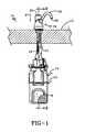
- FIG. 1is a perspective view of a counter mounted dispensing system in accordance with this invention, shown as it might be mounted to a counter;
- FIG. 2is a side, cross-sectional view of the counter mounted dispensing system of FIG. 1 , taken along the line 2 - 2 in FIG. 1 ;
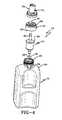
- FIG. 3is a perspective view of the bottle support of the dispensing system
- FIG. 4is an assembly diagram of the product container and pump mechanisms in accordance with a particular embodiment of this invention.
- FIG. 5shows the product container and pump mechanism of FIG. 4 as assembled
- FIG. 6is a perspective view of a collar key used in this invention.
- FIG. 7is a top view of the collar key
- FIG. 8is a bottom view of the collar key
- FIG. 9is a perspective view of a collar key fitted on a product container over pump mechanisms assembled into the product container;
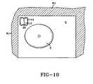
- FIG. 10is a bottom plan view generally representing a an under-the-counter environment in which a counter mounted dispensing system of this invention may be mounted;
- FIG. 11is a perspective view of a bottle support that is to receive a product container, showing the product container out of proper alignment for such receipt;
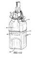
- FIG. 12is a perspective view of a bottle support receiving a product container, the product container being in proper alignment for such receipt;
- FIG. 13is a bottom plan view of the bottle support, showing an optional lock plate therein for interaction with optional elements on a collar key;
- FIGS. 14A-Care exploded views of the interaction of a single protrusion on the collar key with a single protrusion on the release ring of the bottle support, it being appreciated that the other protrusions on the release ring and collar key interact similarly, to selectively retain a production container in the bottle support.
- FIGS. 1 and 2a counter mounted dispensing system in accordance with this invention is shown and designated by the numeral 10 .
- system 10is shown as it might be mounted to a counter C.
- System 10includes product container 12 holding product P to be dispensed when product container 12 is properly mounted in system 10 .
- the product P held within container 12will be a liquid or other generally flowable material that can be pumped against gravity to be dispensed.
- Container 12is received in bottle support 14 , and dispensing head 16 is secured to bottle support 14 at connector 15 , preferably without the need for rotating bottle support 14 relative to head 16 .
- Pumping mechanism 18is secured to container 12 and actuated to dispense product P.
- the present inventionis particularly concerned with hand soap and hand sanitizing dispensers, and therefore, it should be appreciated that the product P may be dispensed as either a liquid or foam, according to the particular type of pump mechanism employed. Virtually any type of pump mechanism 18 may be employed, and, thus, undue emphasis should not be placed on the particular pump mechanism shown in the figures and disclosed herein.
- Dispensing head 16includes plunger 20 , which is pressed downwardly in the direction of arrow A to push pump actuator 22 to operate pump mechanism 18 to force product P through dispensing tube port 24 ( FIG. 4 ) and dispensing tube 26 of pump mechanism 18 , up and out of spout 28 , in the direction of arrow B. More basic or more complicated designs of pump mechanisms and dispensing heads and pump actuators may be employed, as these elements are only of concern in a particular embodiment of this invention. The main focus of this invention is on the concepts relating to the receipt of a product container in a bottle support, particularly in the environment of a counter mounted dispensing system that is mounted in close proximity to a wall. Initially, the elements of the counter mounted dispensing system are disclosed, and the advantages realized when mounting the system close to a wall are disclosed thereafter.
- Bottle support 14is shown alone in FIG. 3 , and includes neck 30 , dispensing head connector 32 , and alignment skirt 34 .
- Alignment skirt 34provides open end 36 for the insertion of container 12
- a container release mechanism generally designated by the numeral 38 and located at neck 30serves to support container 12 when it is fully inserted into bottle support 14 in an appropriate orientation.
- Container release mechanism 38includes release ring 40 , which is rotatably mounted at neck 30 and movable between a container support position and a container release position. Release ring 40 is normally biased to the container support position, in the direction of arrow C, by an appropriate bias force.
- the bias forceis provided here by compression spring 42 , acting between spring plate 44 and ring tab 46 A.
- Alternative biasing meansmay be employed.
- ring tabsare provided and designated by the numeral 46 , and distinguished by letter designations A and B.
- a third ring tabexists in the embodiment shown, spaced substantially equidistant from 46 A and 46 B, but it cannot be seen in the views shown. Movement of release ring 40 in the direction of arrow C is limited by contact between one or more ring tabs 46 A, 46 B (or the unseen ring tab) and associated tab stops 48 A, 48 B (or a stop associated with the unseen ring tab).
- the container release positionis reached by rotating release ring 40 in the direction of arrow D, and movement in that direction is limited by contact between ring tab 46 A and spring plate 44 .
- Ring tab 46 Ais the preferred tab to access when manipulating release ring 40 , because it is easy to grip both spring plate 44 and ring tab 46 A to squeeze ring tab 46 A toward spring plate 44 .
- Container release mechanism 38interacts with a collar key secured on the container 12 , over the pump mechanism, to selectively retain the product container in and release container 12 from bottle support 14 .
- Container 12includes threaded neck 50 defining an open top 52 , which, in accordance with this embodiment, receives a standard foam pump 54 with a one-way valve dip tube 56 .
- Foam pump 54is associated with container 12 by being inserted into open top 52 with radial flange 58 of foam pump 54 resting on open top 52 .
- Threaded cap 59threads onto threaded neck 50 , over foam pump 54 , and provides piston aperture 60 , through which piston 62 of foam pump 54 extends.
- Suction pump member 64snaps onto cap 59 through a snap fit between radial channel 66 , in cap 59 , and radial flange (not seen), on the inside diameter of suction pump member 64 .
- Suction pump member 64is preferably similar to that shown in U.S. Pat. No. 7,431,182 incorporated herein by reference.
- pump mechanism 18is not necessarily pertinent to all aspects of this invention.
- this inventionis not to be limited to or by any particular type of pump mechanism.
- foaming pumps or non-foaming pumpsmay be employed, and pumps employed in this invention need not have suction pump members. Indeed, it is not absolutely necessary that a pump mechanism be carried by the product container inasmuch as the pump mechanics may be provided elsewhere in the dispenser system so long as some type of access is provided to the contents of the product container.
- Container release mechanism 38interacts with a collar key on product container 12 to selectively retain the container in and release the container from bottle support 14 .
- the collar keyis more particularly disclosed with reference to FIGS. 6-9 , wherein it is shown and designated by the numeral 70 .
- Collar key 70fits over suction pump member 64 and cap 59 , and provides actuator aperture 72 for piston portion 65 of suction pump member 64 .
- Aperture 72is disclosed here as an “actuator” aperture because this aperture lets actuator 22 ( FIG. 2 ) ultimately actuate the pump mechanism of foam pump 54 held by container 12 .
- actuator 22actuates pump 54 through contact with piston portion 65 of suction pump 64 , which, in turn, actuates piston 62 of pump 54 , but the invention is not limited thereto or thereby.
- Collar key 70also includes dispensing tube slot 74 for dispensing tube port 24 and dispensing tube 26 ( FIG. 2 ).
- Actuator aperture 72 and dispensing tube slot 74are numbered individually because they do not necessarily have to be provided as one aperture in collar key 70 , as they are shown in the figures.
- Collar key 70is secured to cap 59 by a plurality of inwardly projecting steps 76 that snap under bottom 78 of cap 59 . More particularly, collar key 70 is slid over cap 59 , and the inner dimensions of collar key 70 are such that beveled surfaces 80 of inwardly projecting steps 76 intimately contact cap 59 and are urged outwardly thereby, snapping into place under bottom 78 of cap 59 and being retained by catch surface 81 once steps 76 pass thereby. It is preferred that this permanently locks collar key 70 onto and over cap 59 and the particular pump mechanism (here 18 ) retained thereby. At least one notch 82 on collar key 70 is provided to fit over at least one lug 84 located at the base of neck 50 of container 12 .
- collar key 70when fit over lug 84 in this manner, cannot be rotated relative to container 12 , because such rotation would cause notch 82 to dig into lug 84 and possibly damage container 12 , ultimately poking a hole in lug 84 .
- Bottle support 14is retained under counter C such that an individual installing product container 12 into bottle support 14 must either do so blindly, by reaching under the counter C and installing by feel alone, or must get down below the counter to see the elements involved in the installation.
- Bottle support 14 and product container 12are shown in a preferred mounting position, near a corner of a room, between sink basin S and walls W 1 and W 2 .
- product container 12has a generally rectangular cross-section (but for its detents) and, with such a shape and in such a position of receipt as that shown, cannot be rotate along its vertical axis (represented by the center point drawn on container 12 in FIG. 10 ) because, upon such rotation, the product container would come into contact with one or more of walls W 1 and W 2 and would be forced out of the position of receipt.
- product container 12cannot be configured to be received in bottle support 14 through relative rotation, as, for example, by the threaded engagement typically used in the art.
- a circular cross sectionwould permit relative rotation, but would necessarily provide a refill container of lesser volume, as shown at phantom lines in FIG. 10 .
- product container 12preferably includes a rectangular cross section, fits close to a wall when received in bottle support 14 such that it cannot rotate at that position of receipt, and is received by bottle support 14 without rotating product container 12 relative to bottle support 14 .
- product container 12is simply pushed up into bottle support 14 , and mechanisms interact and move to hold product container 12 .
- product container 12should preferably be positioned in a given orientation for receipt in bottle support 14 . This is true for receiving product container 12 in a specific orientation relative to walls and sink basins under the counter, as just disclosed above, and also for receiving product container 12 in the proper orientation due to structural features on collar key 70 and neck 30 , in order to ensure that the correct type of product is being dispensed and to ensure that the dispensing tube 26 and pump piston 62 are properly oriented for proper actuation of the pump mechanism 18 .
- alignment skirt 34 of bottle support 14includes detent 86 , on at least one sidewall 88 , extending to open end 36
- product container 12likewise has body 90 that includes detent 92 on a complimentary sidewall such that product container 12 may only be inserted into open end 36 of bottle support 14 in a given orientation wherein the cross-sectional shapes of body 90 and alignment skirt 34 are in the same orientation, i.e., with detent 86 aligned with detent 92 .
- product container 12preferably includes at least one finger grip detent 96 that will accept an installer's fingers to provide a place for gripping product container 12 even when very close to a wall, such as wall W 1 or W 2 .
- dispensing tube 26During insertion of container 12 into bottle support 14 , dispensing tube 26 must be inserted up through an aperture in the top of connector 15 , and sloped surface 23 ( FIG. 2 ) is provided in order to urge the flexible dispensing tube 26 toward and through the aperture. Thus, even the threading of the dispensing tube up and through the proper channels can be achieved blindly without squatting down below the counter.
- collar key 70 and neck 30may be “keyed” to one another according to the type of product or products permitted or intended to be dispensed from a given dispensing system.
- Collar key 70 and neck 30may be formed with specific cross-sections, as shown at rib 98 on collar key 70 ( FIGS. 6-9 ), which mates with channel 100 in neck 30 ( FIGS. 11 , 12 ).
- a separate lock plate elementmay also be employed, as shown at the numeral 110 in FIG. 13 .
- Lock plate 110would include male and/or female members at specific locations, and collar key 70 would include complimentary female and/or male members for mating with the male and/or female members on lock plate 110 , such that only a given collar key 70 corresponding with a desired type of product could be received in neck 30 having a given lock plate 110 . This would help with product verification for quality control.
- lock plate 110is shown with male member 112 and collar key 70 is shown with female member 114 at a complimentary location. It should be appreciated that lock plate 110 may be a separate element or may be manufactured directly into neck 30 .
- FIGS. 13 and 14 A-Cshow exploded views of the release ring 40 at ring tab 46 B and its interaction with collar key 70 on container 12 .
- container release mechanism 38interacts with protrusions 120 A, 120 B, 120 C ( FIG. 7 ) on collar key 70 to receive container 12 without the need for rotating container 12 relative to bottle support 14 .
- ramped surfaces 122 A, 122 B, 122 C on protrusions 120 A, 120 B, 120 Ccontact ramped surfaces 124 A, 124 B, 124 C on protrusions 126 A, 126 B, 126 C on release ring 40 , which is biased to the position of FIGS. 3 and 12 by spring 42 acting between spring plate 44 and finger tab 46 A extending from release ring 40 .
- spring 42acting between spring plate 44 and finger tab 46 A extending from release ring 40 .
- continued insertion of product container 12 into bottle support 14causes the various ramped surfaces to push against one another, forcing release ring 40 in the direction of arrow E against spring 42 .
- spring 42forces release ring 40 back to its biased position, and support surfaces 134 A, 134 B, 134 C of protrusions 126 A, 126 B, 126 C rest under support surfaces 136 A, 136 B, 136 C of protrusions 120 A, 120 B, 120 C to hold product container 12 in bottle support 14 .
- spring 42causes release ring 40 to move in the direction of arrow F and “snap” into place once the protrusions pass each other, and this makes it easy for an installer to hear that the product container has been properly installed, even without having to get under a counter and observe the installation.
- Product container 12may be blindly removed from bottle support 14 by feeling for one of finger tabs 46 and moving it against spring 42 to move the support surfaces of the protrusions out of alignment.
Landscapes
- Health & Medical Sciences (AREA)
- Public Health (AREA)
- Closures For Containers (AREA)
- Containers And Packaging Bodies Having A Special Means To Remove Contents (AREA)
Abstract
Description
Claims (1)
Priority Applications (1)
| Application Number | Priority Date | Filing Date | Title |
|---|---|---|---|
| US12/901,732US8087545B2 (en) | 2005-07-25 | 2010-10-11 | Counter mounted dispensing system |
Applications Claiming Priority (2)
| Application Number | Priority Date | Filing Date | Title |
|---|---|---|---|
| US11/188,266US7815074B2 (en) | 2005-07-25 | 2005-07-25 | Counter mounted dispensing system |
| US12/901,732US8087545B2 (en) | 2005-07-25 | 2010-10-11 | Counter mounted dispensing system |
Related Parent Applications (1)
| Application Number | Title | Priority Date | Filing Date |
|---|---|---|---|
| US11/188,266ContinuationUS7815074B2 (en) | 2005-07-25 | 2005-07-25 | Counter mounted dispensing system |
Publications (2)
| Publication Number | Publication Date |
|---|---|
| US20110024447A1 US20110024447A1 (en) | 2011-02-03 |
| US8087545B2true US8087545B2 (en) | 2012-01-03 |
Family
ID=37678125
Family Applications (2)
| Application Number | Title | Priority Date | Filing Date |
|---|---|---|---|
| US11/188,266Active2026-04-25US7815074B2 (en) | 2005-07-25 | 2005-07-25 | Counter mounted dispensing system |
| US12/901,732Expired - Fee RelatedUS8087545B2 (en) | 2005-07-25 | 2010-10-11 | Counter mounted dispensing system |
Family Applications Before (1)
| Application Number | Title | Priority Date | Filing Date |
|---|---|---|---|
| US11/188,266Active2026-04-25US7815074B2 (en) | 2005-07-25 | 2005-07-25 | Counter mounted dispensing system |
Country Status (2)
| Country | Link |
|---|---|
| US (2) | US7815074B2 (en) |
| CA (1) | CA2553111C (en) |
Cited By (14)
| Publication number | Priority date | Publication date | Assignee | Title |
|---|---|---|---|---|
| US20130270300A1 (en)* | 2012-04-17 | 2013-10-17 | Gojo Industries, Inc. | Water-driven dispensing systems employing concentrated product |
| US10278549B1 (en) | 2016-10-31 | 2019-05-07 | Gpcp Ip Holdings Llc | Counter-mounted skincare product dispenser |
| US11253111B2 (en) | 2019-08-22 | 2022-02-22 | Gpcp Ip Holdings Llc | Skin care product dispensers and associated self-foaming compositions |
| US11738988B1 (en) | 2022-11-17 | 2023-08-29 | Sharkninja Operating Llc | Ingredient container valve control |
| US11745996B1 (en) | 2022-11-17 | 2023-09-05 | Sharkninja Operating Llc | Ingredient containers for use with beverage dispensers |
| US11871867B1 (en) | 2023-03-22 | 2024-01-16 | Sharkninja Operating Llc | Additive container with bottom cover |
| US11925287B1 (en) | 2023-03-22 | 2024-03-12 | Sharkninja Operating Llc | Additive container with inlet tube |
| US12084334B2 (en) | 2022-11-17 | 2024-09-10 | Sharkninja Operating Llc | Ingredient container |
| US12096880B2 (en)* | 2022-05-13 | 2024-09-24 | Sharkninja Operating Llc | Flavorant for beverage carbonation system |
| US12103840B2 (en) | 2022-11-17 | 2024-10-01 | Sharkninja Operating Llc | Ingredient container with sealing valve |
| US12116257B1 (en) | 2023-03-22 | 2024-10-15 | Sharkninja Operating Llc | Adapter for beverage dispenser |
| US12213617B2 (en) | 2022-05-13 | 2025-02-04 | Sharkninja Operating Llc | Flavored beverage carbonation process |
| USD1091308S1 (en) | 2022-12-23 | 2025-09-02 | Sharkninja Operating Llc | Ingredient container |
| USD1092208S1 (en) | 2022-12-23 | 2025-09-09 | Sharkninja Operating Llc | Cap of ingredient container |
Families Citing this family (22)
| Publication number | Priority date | Publication date | Assignee | Title |
|---|---|---|---|---|
| US8544698B2 (en) | 2007-03-26 | 2013-10-01 | Gojo Industries, Inc. | Foam soap dispenser with stationary dispensing tube |
| US20090152293A1 (en) | 2007-12-12 | 2009-06-18 | Sayers Richard C | Counter-mounted solution dispenser with counter-protective platform |
| US8100299B2 (en)* | 2007-12-31 | 2012-01-24 | Kimberly-Clark Worldwide, Inc. | Counter-mounted viscous liquid dispenser and mounting system |
| CA2733047A1 (en)* | 2010-03-02 | 2011-09-02 | Gojo Industries, Inc. | Counter mounted dispensing system with above-counter refill unit |
| US8573447B2 (en) | 2010-03-18 | 2013-11-05 | Dispensing Dynamics International | Dispensing system |
| US8485395B2 (en)* | 2011-08-02 | 2013-07-16 | Gojo Industries, Inc. | Dispenser lockout mechanism |
| WO2013119874A2 (en) | 2012-02-08 | 2013-08-15 | Simplehuman, Llc | Liquid dispensing units |
| US9427117B2 (en)* | 2013-02-20 | 2016-08-30 | Keith A. Barclay | Quick disconnect built-in dispenser |
| US8800815B1 (en) | 2013-02-25 | 2014-08-12 | Pibed Limited | Container for use with a counter mounted dispensing system |
| KR101897572B1 (en)* | 2013-06-26 | 2018-10-31 | 코웨이 주식회사 | Apparatus for automatic fluid extracting and method for the same |
| CN104627543B (en)* | 2013-11-11 | 2017-05-10 | 科勒公司 | Dispenser system for disposable wipes |
| US10034584B2 (en) | 2014-03-04 | 2018-07-31 | Gojo Industries, Inc. | Fluid dispenser and fluid refill system for fluid dispenser |
| CA2922625A1 (en)* | 2015-03-06 | 2016-09-06 | Simplehuman, Llc | Foaming soap dispensers |
| US11058261B2 (en) | 2015-07-15 | 2021-07-13 | Gojo Industries, Inc. | Bulk refill protection sensor for dispensing system |
| WO2017120157A1 (en)* | 2016-01-05 | 2017-07-13 | Gojo Industries, Inc. | Systems and methods for monitoring and controlling dispenser fluid refill |
| WO2020232285A1 (en) | 2019-05-16 | 2020-11-19 | Dispensing Dynamics International, Inc. | Fragrance dispensers and methods |
| USD920385S1 (en)* | 2019-08-07 | 2021-05-25 | Dart Industries Inc. | Water pump |
| US11992164B2 (en)* | 2019-09-03 | 2024-05-28 | Peter Bai | Counter mount foam dispenser |
| US11297983B2 (en)* | 2019-09-03 | 2022-04-12 | Peter Bai | Countermount foam dispenser |
| US11234563B2 (en)* | 2019-09-03 | 2022-02-01 | Peter Bai | Countermount foam dispenser |
| CA3147987A1 (en) | 2021-02-05 | 2022-08-05 | Simplehuman, Llc | Push-pump for dispensing soap or other liquids |
| US11759060B2 (en) | 2021-02-08 | 2023-09-19 | Simplehuman, Llc | Portable consumer liquid pump |
Citations (4)
| Publication number | Priority date | Publication date | Assignee | Title |
|---|---|---|---|---|
| US1789338A (en)* | 1929-02-08 | 1931-01-20 | West Disinfecting Co | Liquid-soap-dispensing device |
| US20030089741A1 (en)* | 2001-11-09 | 2003-05-15 | Hubmann Curtis H. | Non-removable device for attaching a dispenser to a container |
| US6929150B2 (en)* | 1999-09-15 | 2005-08-16 | Technical Concepts, Llc | System and method for dispensing soap |
| US7621426B2 (en)* | 2004-12-15 | 2009-11-24 | Joseph Kanfer | Electronically keyed dispensing systems and related methods utilizing near field frequency response |
Family Cites Families (13)
| Publication number | Priority date | Publication date | Assignee | Title |
|---|---|---|---|---|
| US3233787A (en)* | 1962-12-17 | 1966-02-08 | Rollin W Emerson | Foot-operated, bottled-liquid dispensing apparatus |
| US4280638A (en)* | 1979-10-22 | 1981-07-28 | Ici Americas Inc. | Fluid dispensing apparatus |
| US5781942A (en) | 1989-07-12 | 1998-07-21 | Sloan Valve Company | Wash stations and method of operation |
| US5226566A (en) | 1990-09-05 | 1993-07-13 | Scott Paper Company | Modular counter mounted fluid dispensing apparatus |
| US5240147A (en)* | 1991-02-26 | 1993-08-31 | Scott Paper Company | Secured disposable liquid soap dispenser |
| US5332129A (en)* | 1993-06-16 | 1994-07-26 | Moen Incorporated | Soap dispenser assembly |
| US5476197A (en)* | 1995-01-27 | 1995-12-19 | Bobrick Washroom Equipment, Inc. | Spout assembly for fluid dispenser |
| US5632414A (en) | 1995-11-30 | 1997-05-27 | Bobrick Washroom Equipment, Inc. | No-touch fluid dispenser |
| US5832972A (en)* | 1996-07-26 | 1998-11-10 | Ecolab Inc. | Dilution dispensing system with product lock-out |
| US6142342A (en) | 1999-05-28 | 2000-11-07 | Kimberly-Clark Worldwide, Inc. | Counter-mounted viscous liquid dispenser having improved reservoir assembly |
| US6119901A (en)* | 1999-06-03 | 2000-09-19 | Bobrick Washroom Equipment, Inc. | Rotatable coupling for fluid dispenser |
| DE10109671C1 (en)* | 2001-02-28 | 2002-05-02 | Draeger Medical Ag | Device for delivering gas to a ventilator |
| US7025227B2 (en)* | 2003-09-26 | 2006-04-11 | Sloan Valve Company | Electronic soap dispenser |
- 2005
- 2005-07-25USUS11/188,266patent/US7815074B2/enactiveActive
- 2006
- 2006-07-24CACA2553111Apatent/CA2553111C/enactiveActive
- 2010
- 2010-10-11USUS12/901,732patent/US8087545B2/ennot_activeExpired - Fee Related
Patent Citations (4)
| Publication number | Priority date | Publication date | Assignee | Title |
|---|---|---|---|---|
| US1789338A (en)* | 1929-02-08 | 1931-01-20 | West Disinfecting Co | Liquid-soap-dispensing device |
| US6929150B2 (en)* | 1999-09-15 | 2005-08-16 | Technical Concepts, Llc | System and method for dispensing soap |
| US20030089741A1 (en)* | 2001-11-09 | 2003-05-15 | Hubmann Curtis H. | Non-removable device for attaching a dispenser to a container |
| US7621426B2 (en)* | 2004-12-15 | 2009-11-24 | Joseph Kanfer | Electronically keyed dispensing systems and related methods utilizing near field frequency response |
Cited By (20)
| Publication number | Priority date | Publication date | Assignee | Title |
|---|---|---|---|---|
| US20130270300A1 (en)* | 2012-04-17 | 2013-10-17 | Gojo Industries, Inc. | Water-driven dispensing systems employing concentrated product |
| US8851335B2 (en)* | 2012-04-17 | 2014-10-07 | Gojo Industries, Inc. | Water-driven dispensing systems employing concentrated product |
| US20140367421A1 (en)* | 2012-04-17 | 2014-12-18 | Gojo Industries, Inc. | Water-driven dispensing systems employing concentrated product |
| US9301653B2 (en)* | 2012-04-17 | 2016-04-05 | Gojo Industries, Inc. | Water-driven dispensing systems employing concentrated product |
| US10278549B1 (en) | 2016-10-31 | 2019-05-07 | Gpcp Ip Holdings Llc | Counter-mounted skincare product dispenser |
| US11253111B2 (en) | 2019-08-22 | 2022-02-22 | Gpcp Ip Holdings Llc | Skin care product dispensers and associated self-foaming compositions |
| US12213617B2 (en) | 2022-05-13 | 2025-02-04 | Sharkninja Operating Llc | Flavored beverage carbonation process |
| US12096880B2 (en)* | 2022-05-13 | 2024-09-24 | Sharkninja Operating Llc | Flavorant for beverage carbonation system |
| US12006202B1 (en) | 2022-11-17 | 2024-06-11 | Sharkninja Operating Llc | Ingredient container valve control |
| US12084334B2 (en) | 2022-11-17 | 2024-09-10 | Sharkninja Operating Llc | Ingredient container |
| US11745996B1 (en) | 2022-11-17 | 2023-09-05 | Sharkninja Operating Llc | Ingredient containers for use with beverage dispensers |
| US12103840B2 (en) | 2022-11-17 | 2024-10-01 | Sharkninja Operating Llc | Ingredient container with sealing valve |
| US12122661B2 (en) | 2022-11-17 | 2024-10-22 | Sharkninja Operating Llc | Ingredient container valve control |
| US11738988B1 (en) | 2022-11-17 | 2023-08-29 | Sharkninja Operating Llc | Ingredient container valve control |
| US12410048B2 (en) | 2022-11-17 | 2025-09-09 | Sharkninja Operating Llc | Ingredient container |
| USD1091308S1 (en) | 2022-12-23 | 2025-09-02 | Sharkninja Operating Llc | Ingredient container |
| USD1092208S1 (en) | 2022-12-23 | 2025-09-09 | Sharkninja Operating Llc | Cap of ingredient container |
| US11925287B1 (en) | 2023-03-22 | 2024-03-12 | Sharkninja Operating Llc | Additive container with inlet tube |
| US11871867B1 (en) | 2023-03-22 | 2024-01-16 | Sharkninja Operating Llc | Additive container with bottom cover |
| US12116257B1 (en) | 2023-03-22 | 2024-10-15 | Sharkninja Operating Llc | Adapter for beverage dispenser |
Also Published As
| Publication number | Publication date |
|---|---|
| US20110024447A1 (en) | 2011-02-03 |
| CA2553111A1 (en) | 2007-01-25 |
| US20070017932A1 (en) | 2007-01-25 |
| CA2553111C (en) | 2014-09-23 |
| US7815074B2 (en) | 2010-10-19 |
Similar Documents
| Publication | Publication Date | Title |
|---|---|---|
| US8087545B2 (en) | Counter mounted dispensing system | |
| US8640926B2 (en) | Dispenser with flexible cover | |
| US8485395B2 (en) | Dispenser lockout mechanism | |
| JP4573839B2 (en) | Dispenser | |
| US5826755A (en) | Liquid dispenser with selectably attachable actuator | |
| EP3102336B1 (en) | Dispensing pump with cup spring | |
| AU768226B2 (en) | Compact fluid pump | |
| JP2007508915A5 (en) | ||
| US11723494B2 (en) | Dispenser for soap and sanitizer | |
| EP2328690A2 (en) | Pump having a flexible mechanism for engagement with a dispenser | |
| US7290683B2 (en) | Secure surface mounted dispensing system | |
| US9968227B2 (en) | Liquid dispensing system | |
| US6041974A (en) | Wall mounted fluid dispenser | |
| US20080237263A1 (en) | Liquid Dispenser with Reservoir and Pump Attaching Mechanism | |
| HK1096009B (en) | Universal collar key |
Legal Events
| Date | Code | Title | Description |
|---|---|---|---|
| ZAAA | Notice of allowance and fees due | Free format text:ORIGINAL CODE: NOA | |
| ZAAB | Notice of allowance mailed | Free format text:ORIGINAL CODE: MN/=. | |
| STCF | Information on status: patent grant | Free format text:PATENTED CASE | |
| FPAY | Fee payment | Year of fee payment:4 | |
| MAFP | Maintenance fee payment | Free format text:PAYMENT OF MAINTENANCE FEE, 8TH YEAR, LARGE ENTITY (ORIGINAL EVENT CODE: M1552); ENTITY STATUS OF PATENT OWNER: LARGE ENTITY Year of fee payment:8 | |
| AS | Assignment | Owner name:PNC BANK, NATIONAL ASSOCIATION, PENNSYLVANIA Free format text:SECURITY INTEREST;ASSIGNOR:GOJO INDUSTRIES, INC.;REEL/FRAME:051228/0667 Effective date:20101029 | |
| FEPP | Fee payment procedure | Free format text:MAINTENANCE FEE REMINDER MAILED (ORIGINAL EVENT CODE: REM.); ENTITY STATUS OF PATENT OWNER: LARGE ENTITY | |
| AS | Assignment | Owner name:PNC BANK, NATIONAL ASSOCIATION, PENNSYLVANIA Free format text:SECURITY INTEREST;ASSIGNOR:GOJO INDUSTRIES, INC.;REEL/FRAME:065369/0253 Effective date:20231026 | |
| AS | Assignment | Owner name:SILVER POINT FINANCE, LLC, AS COLLATERAL AGENT, CONNECTICUT Free format text:SECURITY INTEREST;ASSIGNOR:GOJO INDUSTRIES, INC.;REEL/FRAME:065382/0587 Effective date:20231026 | |
| LAPS | Lapse for failure to pay maintenance fees | Free format text:PATENT EXPIRED FOR FAILURE TO PAY MAINTENANCE FEES (ORIGINAL EVENT CODE: EXP.); ENTITY STATUS OF PATENT OWNER: LARGE ENTITY | |
| STCH | Information on status: patent discontinuation | Free format text:PATENT EXPIRED DUE TO NONPAYMENT OF MAINTENANCE FEES UNDER 37 CFR 1.362 | |
| FP | Lapsed due to failure to pay maintenance fee | Effective date:20240103 |