US8086318B2 - Portable assemblies, systems, and methods for providing functional or therapeutic neurostimulation - Google Patents
Portable assemblies, systems, and methods for providing functional or therapeutic neurostimulationDownload PDFInfo
- Publication number
- US8086318B2 US8086318B2US11/595,556US59555606AUS8086318B2US 8086318 B2US8086318 B2US 8086318B2US 59555606 AUS59555606 AUS 59555606AUS 8086318 B2US8086318 B2US 8086318B2
- Authority
- US
- United States
- Prior art keywords
- power source
- neurostimulation
- electrode
- circuitry
- assembly
- Prior art date
- Legal status (The legal status is an assumption and is not a legal conclusion. Google has not performed a legal analysis and makes no representation as to the accuracy of the status listed.)
- Active, expires
Links
- 238000000034methodMethods0.000titleabstractdescription37
- 230000000712assemblyEffects0.000titleabstractdescription24
- 238000000429assemblyMethods0.000titleabstractdescription24
- 230000001225therapeutic effectEffects0.000titledescription18
- 230000000638stimulationEffects0.000claimsabstractdescription88
- 230000001070adhesive effectEffects0.000claimsdescription19
- 239000000853adhesiveSubstances0.000claimsdescription17
- 238000004891communicationMethods0.000claimsdescription14
- 230000000007visual effectEffects0.000claimsdescription8
- 238000005286illuminationMethods0.000claimsdescription7
- 210000003205muscleAnatomy0.000abstractdescription49
- 210000005036nerveAnatomy0.000abstractdescription12
- 238000002405diagnostic procedureMethods0.000abstractdescription2
- 238000012154short term therapyMethods0.000abstractdescription2
- 210000001519tissueAnatomy0.000description32
- 238000011282treatmentMethods0.000description30
- 230000006870functionEffects0.000description23
- 239000006187pillSubstances0.000description22
- 239000003814drugSubstances0.000description15
- 238000002560therapeutic procedureMethods0.000description15
- 229940079593drugDrugs0.000description14
- 208000002193PainDiseases0.000description12
- 230000033001locomotionEffects0.000description12
- 238000004873anchoringMethods0.000description8
- 230000008878couplingEffects0.000description8
- 238000010168coupling processMethods0.000description8
- 238000005859coupling reactionMethods0.000description8
- 238000002513implantationMethods0.000description8
- 230000002093peripheral effectEffects0.000description8
- 230000008901benefitEffects0.000description7
- 230000000694effectsEffects0.000description7
- 238000001356surgical procedureMethods0.000description7
- 230000035876healingEffects0.000description6
- 239000000463materialSubstances0.000description6
- 230000013011matingEffects0.000description6
- 230000000737periodic effectEffects0.000description6
- 230000002441reversible effectEffects0.000description6
- 208000027418Wounds and injuryDiseases0.000description5
- 238000005452bendingMethods0.000description5
- 210000000988bone and boneAnatomy0.000description5
- 210000004556brainAnatomy0.000description5
- 230000003750conditioning effectEffects0.000description5
- 239000004020conductorSubstances0.000description5
- 210000003414extremityAnatomy0.000description5
- 239000007943implantSubstances0.000description5
- 208000014674injuryDiseases0.000description5
- 238000011084recoveryMethods0.000description5
- 230000004936stimulating effectEffects0.000description5
- 208000001132OsteoporosisDiseases0.000description4
- 239000003990capacitorSubstances0.000description4
- 238000009434installationMethods0.000description4
- 229910052751metalInorganic materials0.000description4
- 230000002232neuromuscularEffects0.000description4
- 230000008569processEffects0.000description4
- 239000004820Pressure-sensitive adhesiveSubstances0.000description3
- 208000005392SpasmDiseases0.000description3
- 230000003385bacteriostatic effectEffects0.000description3
- 230000002051biphasic effectEffects0.000description3
- 230000015556catabolic processEffects0.000description3
- 230000002354daily effectEffects0.000description3
- 230000006378damageEffects0.000description3
- 238000006731degradation reactionMethods0.000description3
- 238000003745diagnosisMethods0.000description3
- 208000037265diseases, disorders, signs and symptomsDiseases0.000description3
- 230000004064dysfunctionEffects0.000description3
- 238000005516engineering processMethods0.000description3
- 230000005284excitationEffects0.000description3
- 208000015181infectious diseaseDiseases0.000description3
- 238000003780insertionMethods0.000description3
- 230000037431insertionEffects0.000description3
- 238000007726management methodMethods0.000description3
- 239000002184metalSubstances0.000description3
- 230000037230mobilityEffects0.000description3
- 230000004118muscle contractionEffects0.000description3
- 230000004220muscle functionEffects0.000description3
- 230000003387muscularEffects0.000description3
- 230000004007neuromodulationEffects0.000description3
- 230000004044responseEffects0.000description3
- 230000037390scarringEffects0.000description3
- 210000001364upper extremityAnatomy0.000description3
- 208000007101Muscle CrampDiseases0.000description2
- 206010040880Skin irritationDiseases0.000description2
- 208000006011StrokeDiseases0.000description2
- 108010057266Type A Botulinum ToxinsProteins0.000description2
- 206010052428WoundDiseases0.000description2
- 230000009471actionEffects0.000description2
- 210000003484anatomyAnatomy0.000description2
- 230000002785anti-thrombosisEffects0.000description2
- 210000004369bloodAnatomy0.000description2
- 239000008280bloodSubstances0.000description2
- 229940089093botoxDrugs0.000description2
- 244000309466calfSpecies0.000description2
- 210000003169central nervous systemAnatomy0.000description2
- 210000002808connective tissueAnatomy0.000description2
- 238000010276constructionMethods0.000description2
- 230000008602contractionEffects0.000description2
- 239000013078crystalSubstances0.000description2
- 125000004122cyclic groupChemical group0.000description2
- 238000010586diagramMethods0.000description2
- 201000010099diseaseDiseases0.000description2
- 230000003203everyday effectEffects0.000description2
- 230000005021gaitEffects0.000description2
- 230000001976improved effectEffects0.000description2
- 230000030214innervationEffects0.000description2
- 230000002452interceptive effectEffects0.000description2
- 210000003141lower extremityAnatomy0.000description2
- 238000012423maintenanceMethods0.000description2
- 230000007246mechanismEffects0.000description2
- 239000007769metal materialSubstances0.000description2
- 239000002991molded plasticSubstances0.000description2
- 201000006417multiple sclerosisDiseases0.000description2
- 230000001537neural effectEffects0.000description2
- 238000004806packaging method and processMethods0.000description2
- 239000004033plasticSubstances0.000description2
- 230000002980postoperative effectEffects0.000description2
- 230000002028prematureEffects0.000description2
- 239000010453quartzSubstances0.000description2
- 210000002979radial nerveAnatomy0.000description2
- 231100000241scarToxicity0.000description2
- 239000000565sealantSubstances0.000description2
- VYPSYNLAJGMNEJ-UHFFFAOYSA-Nsilicon dioxideInorganic materialsO=[Si]=OVYPSYNLAJGMNEJ-UHFFFAOYSA-N0.000description2
- NDVLTYZPCACLMA-UHFFFAOYSA-Nsilver oxideChemical compound[O-2].[Ag+].[Ag+]NDVLTYZPCACLMA-UHFFFAOYSA-N0.000description2
- 230000036556skin irritationEffects0.000description2
- 231100000475skin irritationToxicity0.000description2
- 210000001738temporomandibular jointAnatomy0.000description2
- 238000012546transferMethods0.000description2
- 230000008733traumaEffects0.000description2
- 206010011906DeathDiseases0.000description1
- 208000005189EmbolismDiseases0.000description1
- 206010019196Head injuryDiseases0.000description1
- 206010061218InflammationDiseases0.000description1
- WHXSMMKQMYFTQS-UHFFFAOYSA-NLithiumChemical compound[Li]WHXSMMKQMYFTQS-UHFFFAOYSA-N0.000description1
- 208000008238Muscle SpasticityDiseases0.000description1
- 208000010428Muscle WeaknessDiseases0.000description1
- 206010028372Muscular weaknessDiseases0.000description1
- 208000023178Musculoskeletal diseaseDiseases0.000description1
- 206010033799ParalysisDiseases0.000description1
- 239000004642PolyimideSubstances0.000description1
- 206010037714QuadriplegiaDiseases0.000description1
- 208000002847Surgical WoundDiseases0.000description1
- 208000001435ThromboembolismDiseases0.000description1
- 208000007536ThrombosisDiseases0.000description1
- 206010046543Urinary incontinenceDiseases0.000description1
- 230000003187abdominal effectEffects0.000description1
- 230000004913activationEffects0.000description1
- 208000005298acute painDiseases0.000description1
- 230000003044adaptive effectEffects0.000description1
- 238000004026adhesive bondingMethods0.000description1
- 230000003466anti-cipated effectEffects0.000description1
- 238000013459approachMethods0.000description1
- 208000020538atrophic muscular diseaseDiseases0.000description1
- 229920000249biocompatible polymerPolymers0.000description1
- 230000004397blinkingEffects0.000description1
- 230000000903blocking effectEffects0.000description1
- 230000017531blood circulationEffects0.000description1
- 230000036770blood supplyEffects0.000description1
- 230000010478bone regenerationEffects0.000description1
- 239000012876carrier materialSubstances0.000description1
- 208000015114central nervous system diseaseDiseases0.000description1
- 230000002490cerebral effectEffects0.000description1
- 206010008129cerebral palsyDiseases0.000description1
- 230000008859changeEffects0.000description1
- 230000001055chewing effectEffects0.000description1
- 230000001684chronic effectEffects0.000description1
- 239000003086colorantSubstances0.000description1
- 230000006835compressionEffects0.000description1
- 238000007906compressionMethods0.000description1
- 230000001010compromised effectEffects0.000description1
- 229920001940conductive polymerPolymers0.000description1
- 230000001054cortical effectEffects0.000description1
- 230000003247decreasing effectEffects0.000description1
- 230000007850degenerationEffects0.000description1
- 210000000852deltoid muscleAnatomy0.000description1
- 230000001419dependent effectEffects0.000description1
- 238000013461designMethods0.000description1
- 238000001514detection methodMethods0.000description1
- 208000035475disorderDiseases0.000description1
- 230000009977dual effectEffects0.000description1
- 230000007937eatingEffects0.000description1
- 230000002526effect on cardiovascular systemEffects0.000description1
- 230000002500effect on skinEffects0.000description1
- 229920001971elastomerPolymers0.000description1
- 239000000806elastomerSubstances0.000description1
- 206010015037epilepsyDiseases0.000description1
- 238000011156evaluationMethods0.000description1
- 238000012854evaluation processMethods0.000description1
- 210000000744eyelidAnatomy0.000description1
- 230000008921facial expressionEffects0.000description1
- 238000001914filtrationMethods0.000description1
- 239000000796flavoring agentSubstances0.000description1
- 235000019634flavorsNutrition0.000description1
- 230000003370grooming effectEffects0.000description1
- 230000036541healthEffects0.000description1
- 230000001771impaired effectEffects0.000description1
- 230000001939inductive effectEffects0.000description1
- 230000004054inflammatory processEffects0.000description1
- 230000016507interphaseEffects0.000description1
- 229910001947lithium oxideInorganic materials0.000description1
- 238000013508migrationMethods0.000description1
- 230000005012migrationEffects0.000description1
- 238000012544monitoring processMethods0.000description1
- 230000007383nerve stimulationEffects0.000description1
- 230000001508neuroinhibitory effectEffects0.000description1
- 230000007971neurological deficitEffects0.000description1
- 230000000926neurological effectEffects0.000description1
- 239000002581neurotoxinSubstances0.000description1
- 231100000618neurotoxinToxicity0.000description1
- 210000000056organAnatomy0.000description1
- 230000008520organizationEffects0.000description1
- 230000000399orthopedic effectEffects0.000description1
- 239000000123paperSubstances0.000description1
- 230000001769paralizing effectEffects0.000description1
- 230000036961partial effectEffects0.000description1
- 210000005259peripheral bloodAnatomy0.000description1
- 239000011886peripheral bloodSubstances0.000description1
- 210000001428peripheral nervous systemAnatomy0.000description1
- 239000002985plastic filmSubstances0.000description1
- 229920000052poly(p-xylylene)Polymers0.000description1
- 229920001721polyimidePolymers0.000description1
- 229920000642polymerPolymers0.000description1
- 239000002861polymer materialSubstances0.000description1
- 238000011176poolingMethods0.000description1
- 230000002265preventionEffects0.000description1
- 238000012545processingMethods0.000description1
- 230000002035prolonged effectEffects0.000description1
- 238000011321prophylaxisMethods0.000description1
- 238000011002quantificationMethods0.000description1
- 230000009467reductionEffects0.000description1
- 230000002829reductive effectEffects0.000description1
- 230000001105regulatory effectEffects0.000description1
- 230000002040relaxant effectEffects0.000description1
- 238000011160researchMethods0.000description1
- 238000012552reviewMethods0.000description1
- 239000004065semiconductorSubstances0.000description1
- 230000001953sensory effectEffects0.000description1
- 238000012163sequencing techniqueMethods0.000description1
- 229910001923silver oxideInorganic materials0.000description1
- 208000017520skin diseaseDiseases0.000description1
- 208000018198spasticityDiseases0.000description1
- 210000000278spinal cordAnatomy0.000description1
- 208000020431spinal cord injuryDiseases0.000description1
- 210000002784stomachAnatomy0.000description1
- 238000007920subcutaneous administrationMethods0.000description1
- 239000013589supplementSubstances0.000description1
- 238000011477surgical interventionMethods0.000description1
- 230000009747swallowingEffects0.000description1
- 230000017423tissue regenerationEffects0.000description1
- 238000012549trainingMethods0.000description1
- 239000012780transparent materialSubstances0.000description1
- 230000007384vagal nerve stimulationEffects0.000description1
- 230000021542voluntary musculoskeletal movementEffects0.000description1
- XLYOFNOQVPJJNP-UHFFFAOYSA-NwaterSubstancesOXLYOFNOQVPJJNP-UHFFFAOYSA-N0.000description1
- 238000005303weighingMethods0.000description1
- 238000003466weldingMethods0.000description1
- 230000037303wrinklesEffects0.000description1
Images


Classifications
- A—HUMAN NECESSITIES
- A61—MEDICAL OR VETERINARY SCIENCE; HYGIENE
- A61N—ELECTROTHERAPY; MAGNETOTHERAPY; RADIATION THERAPY; ULTRASOUND THERAPY
- A61N1/00—Electrotherapy; Circuits therefor
- A61N1/18—Applying electric currents by contact electrodes
- A61N1/32—Applying electric currents by contact electrodes alternating or intermittent currents
- A61N1/36—Applying electric currents by contact electrodes alternating or intermittent currents for stimulation
- A61N1/36014—External stimulators, e.g. with patch electrodes
- A61N1/36017—External stimulators, e.g. with patch electrodes with leads or electrodes penetrating the skin
- A—HUMAN NECESSITIES
- A61—MEDICAL OR VETERINARY SCIENCE; HYGIENE
- A61N—ELECTROTHERAPY; MAGNETOTHERAPY; RADIATION THERAPY; ULTRASOUND THERAPY
- A61N1/00—Electrotherapy; Circuits therefor
- A61N1/02—Details
- A61N1/04—Electrodes
- A61N1/0404—Electrodes for external use
- A61N1/0408—Use-related aspects
- A61N1/0456—Specially adapted for transcutaneous electrical nerve stimulation [TENS]
- A—HUMAN NECESSITIES
- A61—MEDICAL OR VETERINARY SCIENCE; HYGIENE
- A61N—ELECTROTHERAPY; MAGNETOTHERAPY; RADIATION THERAPY; ULTRASOUND THERAPY
- A61N1/00—Electrotherapy; Circuits therefor
- A61N1/02—Details
- A61N1/04—Electrodes
- A61N1/0404—Electrodes for external use
- A61N1/0472—Structure-related aspects
- A61N1/0492—Patch electrodes
- A—HUMAN NECESSITIES
- A61—MEDICAL OR VETERINARY SCIENCE; HYGIENE
- A61N—ELECTROTHERAPY; MAGNETOTHERAPY; RADIATION THERAPY; ULTRASOUND THERAPY
- A61N1/00—Electrotherapy; Circuits therefor
- A61N1/18—Applying electric currents by contact electrodes
- A61N1/32—Applying electric currents by contact electrodes alternating or intermittent currents
- A61N1/36—Applying electric currents by contact electrodes alternating or intermittent currents for stimulation
- A61N1/36003—Applying electric currents by contact electrodes alternating or intermittent currents for stimulation of motor muscles, e.g. for walking assistance
- A—HUMAN NECESSITIES
- A61—MEDICAL OR VETERINARY SCIENCE; HYGIENE
- A61N—ELECTROTHERAPY; MAGNETOTHERAPY; RADIATION THERAPY; ULTRASOUND THERAPY
- A61N1/00—Electrotherapy; Circuits therefor
- A61N1/18—Applying electric currents by contact electrodes
- A61N1/32—Applying electric currents by contact electrodes alternating or intermittent currents
- A61N1/36—Applying electric currents by contact electrodes alternating or intermittent currents for stimulation
- A61N1/36014—External stimulators, e.g. with patch electrodes
- A61N1/36021—External stimulators, e.g. with patch electrodes for treatment of pain
- A—HUMAN NECESSITIES
- A61—MEDICAL OR VETERINARY SCIENCE; HYGIENE
- A61N—ELECTROTHERAPY; MAGNETOTHERAPY; RADIATION THERAPY; ULTRASOUND THERAPY
- A61N1/00—Electrotherapy; Circuits therefor
- A61N1/18—Applying electric currents by contact electrodes
- A61N1/32—Applying electric currents by contact electrodes alternating or intermittent currents
- A61N1/36—Applying electric currents by contact electrodes alternating or intermittent currents for stimulation
- A61N1/372—Arrangements in connection with the implantation of stimulators
- A61N1/37211—Means for communicating with stimulators
- A61N1/37235—Aspects of the external programmer
- A61N1/37247—User interfaces, e.g. input or presentation means
- A—HUMAN NECESSITIES
- A61—MEDICAL OR VETERINARY SCIENCE; HYGIENE
- A61N—ELECTROTHERAPY; MAGNETOTHERAPY; RADIATION THERAPY; ULTRASOUND THERAPY
- A61N1/00—Electrotherapy; Circuits therefor
- A61N1/18—Applying electric currents by contact electrodes
- A61N1/32—Applying electric currents by contact electrodes alternating or intermittent currents
- A61N1/36—Applying electric currents by contact electrodes alternating or intermittent currents for stimulation
- A61N1/372—Arrangements in connection with the implantation of stimulators
- A61N1/378—Electrical supply
- H—ELECTRICITY
- H01—ELECTRIC ELEMENTS
- H01M—PROCESSES OR MEANS, e.g. BATTERIES, FOR THE DIRECT CONVERSION OF CHEMICAL ENERGY INTO ELECTRICAL ENERGY
- H01M50/00—Constructional details or processes of manufacture of the non-active parts of electrochemical cells other than fuel cells, e.g. hybrid cells
- H01M50/20—Mountings; Secondary casings or frames; Racks, modules or packs; Suspension devices; Shock absorbers; Transport or carrying devices; Holders
- H01M50/204—Racks, modules or packs for multiple batteries or multiple cells
- H01M50/207—Racks, modules or packs for multiple batteries or multiple cells characterised by their shape
- H01M50/213—Racks, modules or packs for multiple batteries or multiple cells characterised by their shape adapted for cells having curved cross-section, e.g. round or elliptic
- A—HUMAN NECESSITIES
- A61—MEDICAL OR VETERINARY SCIENCE; HYGIENE
- A61H—PHYSICAL THERAPY APPARATUS, e.g. DEVICES FOR LOCATING OR STIMULATING REFLEX POINTS IN THE BODY; ARTIFICIAL RESPIRATION; MASSAGE; BATHING DEVICES FOR SPECIAL THERAPEUTIC OR HYGIENIC PURPOSES OR SPECIFIC PARTS OF THE BODY
- A61H39/00—Devices for locating or stimulating specific reflex points of the body for physical therapy, e.g. acupuncture
- A61H39/002—Using electric currents
- A—HUMAN NECESSITIES
- A61—MEDICAL OR VETERINARY SCIENCE; HYGIENE
- A61N—ELECTROTHERAPY; MAGNETOTHERAPY; RADIATION THERAPY; ULTRASOUND THERAPY
- A61N1/00—Electrotherapy; Circuits therefor
- A61N1/02—Details
- A61N1/04—Electrodes
- A61N1/05—Electrodes for implantation or insertion into the body, e.g. heart electrode
- A61N1/0526—Head electrodes
- A61N1/0529—Electrodes for brain stimulation
- A—HUMAN NECESSITIES
- A61—MEDICAL OR VETERINARY SCIENCE; HYGIENE
- A61N—ELECTROTHERAPY; MAGNETOTHERAPY; RADIATION THERAPY; ULTRASOUND THERAPY
- A61N1/00—Electrotherapy; Circuits therefor
- A61N1/02—Details
- A61N1/04—Electrodes
- A61N1/05—Electrodes for implantation or insertion into the body, e.g. heart electrode
- A61N1/0551—Spinal or peripheral nerve electrodes
- A—HUMAN NECESSITIES
- A61—MEDICAL OR VETERINARY SCIENCE; HYGIENE
- A61N—ELECTROTHERAPY; MAGNETOTHERAPY; RADIATION THERAPY; ULTRASOUND THERAPY
- A61N1/00—Electrotherapy; Circuits therefor
- A61N1/18—Applying electric currents by contact electrodes
- A61N1/32—Applying electric currents by contact electrodes alternating or intermittent currents
- A61N1/36—Applying electric currents by contact electrodes alternating or intermittent currents for stimulation
- A61N1/36014—External stimulators, e.g. with patch electrodes
- A61N1/3603—Control systems
- A61N1/36034—Control systems specified by the stimulation parameters
- Y—GENERAL TAGGING OF NEW TECHNOLOGICAL DEVELOPMENTS; GENERAL TAGGING OF CROSS-SECTIONAL TECHNOLOGIES SPANNING OVER SEVERAL SECTIONS OF THE IPC; TECHNICAL SUBJECTS COVERED BY FORMER USPC CROSS-REFERENCE ART COLLECTIONS [XRACs] AND DIGESTS
- Y02—TECHNOLOGIES OR APPLICATIONS FOR MITIGATION OR ADAPTATION AGAINST CLIMATE CHANGE
- Y02E—REDUCTION OF GREENHOUSE GAS [GHG] EMISSIONS, RELATED TO ENERGY GENERATION, TRANSMISSION OR DISTRIBUTION
- Y02E60/00—Enabling technologies; Technologies with a potential or indirect contribution to GHG emissions mitigation
- Y02E60/10—Energy storage using batteries
Definitions
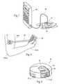
- Another aspect of the inventionprovides assemblies, systems, and methods for providing neurostimulation comprising at least one electrode, a carrier sized and configured to be worn by a user, an electronics pod removably carried on-board the carrier, the electronics pod including circuitry configured to generate a stimulation pulse to the electrode, and a power input bay carried on-board the electronics pod that is electrically coupled to the circuitry, the power input bay being sized and configured to accept a disposable power source.
- FIG. 7is a perspective view of a neurostimulation assembly of the type shown in FIG. 1 coupled to an external programming instrument.
- At least a portion of, and likely a larger surface area than the undersurface of the carrier 16includes a disposable adhesive region or patch 18 .
- the adhesive region 18may be an integral component of the carrier 16 (as shown in 3 A), or a separate component (as shown in 3 B).
- the function of the adhesive region 18is to temporarily secure the carrier 16 to an external skin surface during use.
- an inert, conventional pressure sensitive adhesive or tapecan be used.
- the dermal adhesive regioncontains a bacteriostatic sealant that prevents skin irritation or superficial infection, which could lead to premature removal.
- an individualwill be instructed to remove and discard the power source 32 about once a day, replacing it with a fresh power source 32 .
- This arrangementsimplifies meeting the power demands of the electronics pod 20 while easily allowing the prescription of therapies of differing duration (e.g., remove and replace the power source every other day or once a week to provide the stimulation on a prescribed, intermittent basis).
- the use of the neurostimulation assembly 10will thereby parallel a normal, accustomed medication regime, with the power source 32 being replaced in the same frequency an individual administers medication in pill form.
- the power source 32may be provided in an over-molded housing 34 to ease attachment and removal.
- the microcontroller circuitry 24may be responsible for the following functions:
- the power sourceis isolated from all circuitry via a MOSFET switch that requires active closure by the circuitry on the power source.
- the microcontroller circuit 24monitors VHH for detection of a VHH power supply failure, system failures, and optimizing VHH for the exhibited electrode circuit impedance.
- Microcontroller circuitry 24selects the electrode connections to carry the stimulus current (and time the interphase delay) via address lines.
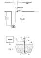
- the electrode 14 and lead 12can comprise, e.g., one or more coiled metal wires with in an open or flexible elastomer core.
- the wirecan be insulated, e.g., with a biocompatible polymer film, such as polyfluorocarbon, polyimide, or parylene.
- the electrode 14 and lead 12are desirably coated with a textured, bacteriostatic material, which helps to stabilize the electrode in a way that still permits easy removal at a later date and increases tolerance.
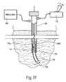
- the following illustrationwill describe the use of a neurostimulator assembly 10 that will be worn on the patient's exterior skin surface. It is to be appreciated that the neurostimulator assembly 10 could be carried by the patient or temporarily secured to a bed or other structure and the lead(s) 12 extend to the assembly 10 .
- the carrier 16is placed on the skin in a desirable region that allows electrical connectivity to the lead 12 and associated connector 29 ′ (see FIGS. 2 and 3A ).
- the carrier 16is secured in place with the pressure sensitive adhesive 18 on the bottom of the carrier.
- the adhesive regiondesirably contains a bacteriostatic sealant that prevents skin irritation or superficial infection, which could lead to premature removal.
- Instructions for use 56may accompany the neurostimulation system 54 .
- the instructions 56prescribe use of the neurostimulation assembly 10 , including the periodic removal and replacement of the power source 32 with a fresh power source 32 .
- the instructions 56prescribe a neurostimulation regime that includes a periodic “powering” or dosing, via power source replacement, of the neurostimulation assembly 10 in the same fashion that pill-based medication regime directs periodic “dosing” of the medication by taking of a pill.
- a power source 32becomes the therapeutic equivalent of a pill (i.e., it is part of a user action taken to extend treatment).
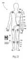
- C5-6 tetraplegicsare unable to extend their elbow. Without elbow extension, they are limited to accessing only the area directly in front of their body, requiring assistance in many of their activities of daily living. They rely on the use of their biceps muscle to perform most of their upper extremity tasks. With limited or no hand function they rely on adaptive equipment to accomplish many self care activities such as grooming and hygiene as well as feeding.
- the individualwill be scheduled for a second phase of treatment if electrical stimulation of the radial nerve innervation to the triceps using the surface or percutaneous stimulation program provides active elbow extension expanding the individual's previous work space.
- the neurostimulation system 150also desirably includes a container 52 holding a prescribed number of replacement power sources 32 , and instructions for use 56 that prescribe use of the neurostimulation assembly 102 , including the periodic removal and replacement of a power source 32 with a fresh power source 32 .
- Localized pain in any area of the bodycan be treated with the neurostimulation assembly 10 and/or neurostimulation system 54 by applying it directly to the effected area.
- the neurostimulation assembly 10 and/or neurostimulation system 54works by interfering with or blocking pain signals from reaching the brain.
Landscapes
- Health & Medical Sciences (AREA)
- Life Sciences & Earth Sciences (AREA)
- Engineering & Computer Science (AREA)
- Veterinary Medicine (AREA)
- Nuclear Medicine, Radiotherapy & Molecular Imaging (AREA)
- Radiology & Medical Imaging (AREA)
- Biomedical Technology (AREA)
- Animal Behavior & Ethology (AREA)
- General Health & Medical Sciences (AREA)
- Public Health (AREA)
- Biophysics (AREA)
- Heart & Thoracic Surgery (AREA)
- Pain & Pain Management (AREA)
- Human Computer Interaction (AREA)
- Physical Education & Sports Medicine (AREA)
- Chemical & Material Sciences (AREA)
- Chemical Kinetics & Catalysis (AREA)
- Electrochemistry (AREA)
- General Chemical & Material Sciences (AREA)
- Electrotherapy Devices (AREA)
Abstract
Description
Claims (9)
Priority Applications (11)
| Application Number | Priority Date | Filing Date | Title |
|---|---|---|---|
| US11/595,556US8086318B2 (en) | 2004-02-12 | 2006-11-10 | Portable assemblies, systems, and methods for providing functional or therapeutic neurostimulation |
| US11/729,333US8467875B2 (en) | 2004-02-12 | 2007-03-28 | Stimulation of dorsal genital nerves to treat urologic dysfunctions |
| AU2007254204AAU2007254204A1 (en) | 2006-05-18 | 2007-05-17 | Portable assemblies, systems, and methods for providing functional or therapeutic neurostimulation |
| JP2009511074AJP2009537226A (en) | 2006-05-18 | 2007-05-17 | Portable assembly, system, and method for providing functional or therapeutic neural stimulation |
| CA002652565ACA2652565A1 (en) | 2006-05-18 | 2007-05-17 | Portable assemblies, systems, and methods for providing functional or therapeutic neurostimulation |
| PCT/US2007/011867WO2007136726A2 (en) | 2006-05-18 | 2007-05-17 | Portable assemblies, systems, and methods for providing functional or therapeutic neurostimulation |
| EP07777138AEP2024018A4 (en) | 2006-05-18 | 2007-05-17 | Portable assemblies, systems, and methods for providing functional or therapeutic neurostimulation |
| US11/978,824US20080065182A1 (en) | 2004-02-12 | 2007-10-30 | Portable assemblies, systems, and methods for providing functional or therapeutic neurostimulation |
| US11/981,424US20080161874A1 (en) | 2004-02-12 | 2007-10-31 | Systems and methods for a trial stage and/or long-term treatment of disorders of the body using neurostimulation |
| US11/981,113US20080132969A1 (en) | 2004-02-12 | 2007-10-31 | Systems and methods for bilateral stimulation of left and right branches of the dorsal genital nerves to treat urologic dysfunctions |
| US13/173,957US20110257701A1 (en) | 2004-02-12 | 2011-06-30 | Portable assemblies, systems and methods for providing functional or therapeutic neurostimulation |
Applications Claiming Priority (5)
| Application Number | Priority Date | Filing Date | Title |
|---|---|---|---|
| US10/777,771US7120499B2 (en) | 2004-02-12 | 2004-02-12 | Portable percutaneous assemblies, systems and methods for providing highly selective functional or therapeutic neuromuscular stimulation |
| US55194504P | 2004-03-10 | 2004-03-10 | |
| US11/056,591US7376467B2 (en) | 2004-02-12 | 2005-02-11 | Portable assemblies, systems and methods for providing functional or therapeutic neuromuscular stimulation |
| US80131506P | 2006-05-18 | 2006-05-18 | |
| US11/595,556US8086318B2 (en) | 2004-02-12 | 2006-11-10 | Portable assemblies, systems, and methods for providing functional or therapeutic neurostimulation |
Related Parent Applications (2)
| Application Number | Title | Priority Date | Filing Date |
|---|---|---|---|
| US10/777,771Continuation-In-PartUS7120499B2 (en) | 2004-02-12 | 2004-02-12 | Portable percutaneous assemblies, systems and methods for providing highly selective functional or therapeutic neuromuscular stimulation |
| US11/056,591Continuation-In-PartUS7376467B2 (en) | 2004-02-12 | 2005-02-11 | Portable assemblies, systems and methods for providing functional or therapeutic neuromuscular stimulation |
Related Child Applications (3)
| Application Number | Title | Priority Date | Filing Date |
|---|---|---|---|
| US11/149,654Continuation-In-PartUS7565198B2 (en) | 2003-09-12 | 2005-06-10 | Systems and methods for bilateral stimulation of left and right branches of the dorsal genital nerves to treat dysfunctions, such as urinary incontinence |
| US11/729,333Continuation-In-PartUS8467875B2 (en) | 2004-02-12 | 2007-03-28 | Stimulation of dorsal genital nerves to treat urologic dysfunctions |
| US11/978,824DivisionUS20080065182A1 (en) | 2004-02-12 | 2007-10-30 | Portable assemblies, systems, and methods for providing functional or therapeutic neurostimulation |
Publications (2)
| Publication Number | Publication Date |
|---|---|
| US20070123952A1 US20070123952A1 (en) | 2007-05-31 |
| US8086318B2true US8086318B2 (en) | 2011-12-27 |
Family
ID=38122317
Family Applications (3)
| Application Number | Title | Priority Date | Filing Date |
|---|---|---|---|
| US11/595,556Active2027-09-20US8086318B2 (en) | 2004-02-12 | 2006-11-10 | Portable assemblies, systems, and methods for providing functional or therapeutic neurostimulation |
| US11/978,824AbandonedUS20080065182A1 (en) | 2004-02-12 | 2007-10-30 | Portable assemblies, systems, and methods for providing functional or therapeutic neurostimulation |
| US13/173,957AbandonedUS20110257701A1 (en) | 2004-02-12 | 2011-06-30 | Portable assemblies, systems and methods for providing functional or therapeutic neurostimulation |
Family Applications After (2)
| Application Number | Title | Priority Date | Filing Date |
|---|---|---|---|
| US11/978,824AbandonedUS20080065182A1 (en) | 2004-02-12 | 2007-10-30 | Portable assemblies, systems, and methods for providing functional or therapeutic neurostimulation |
| US13/173,957AbandonedUS20110257701A1 (en) | 2004-02-12 | 2011-06-30 | Portable assemblies, systems and methods for providing functional or therapeutic neurostimulation |
Country Status (1)
| Country | Link |
|---|---|
| US (3) | US8086318B2 (en) |
Cited By (71)
| Publication number | Priority date | Publication date | Assignee | Title |
|---|---|---|---|---|
| US20100036445A1 (en)* | 2008-08-01 | 2010-02-11 | Ndi Medical Llc. | Portable assemblies, systems, and methods for providing functional or therapeutic neurostimulation |
| US8903494B2 (en) | 2012-11-26 | 2014-12-02 | Thync, Inc. | Wearable transdermal electrical stimulation devices and methods of using them |
| US20140371802A1 (en)* | 2013-06-17 | 2014-12-18 | Adi Mashiach | Flexible Control Housing for Disposable Patch |
| US9002458B2 (en) | 2013-06-29 | 2015-04-07 | Thync, Inc. | Transdermal electrical stimulation devices for modifying or inducing cognitive state |
| US9101768B2 (en) | 2013-03-15 | 2015-08-11 | Globus Medical, Inc. | Spinal cord stimulator system |
| US9333334B2 (en) | 2014-05-25 | 2016-05-10 | Thync, Inc. | Methods for attaching and wearing a neurostimulator |
| US9393401B2 (en) | 2014-05-25 | 2016-07-19 | Thync Global, Inc. | Wearable transdermal neurostimulator having cantilevered attachment |
| US9393430B2 (en) | 2014-05-17 | 2016-07-19 | Thync Global, Inc. | Methods and apparatuses for control of a wearable transdermal neurostimulator to apply ensemble waveforms |
| US9399126B2 (en) | 2014-02-27 | 2016-07-26 | Thync Global, Inc. | Methods for user control of neurostimulation to modify a cognitive state |
| US9440070B2 (en) | 2012-11-26 | 2016-09-13 | Thyne Global, Inc. | Wearable transdermal electrical stimulation devices and methods of using them |
| US9452287B2 (en) | 2013-01-21 | 2016-09-27 | Cala Health, Inc. | Devices and methods for controlling tremor |
| US9592160B2 (en) | 2014-09-16 | 2017-03-14 | Garwood Medical Devices, Llc | Wound care bandage and method of wound healing |
| US20170136228A1 (en)* | 2014-05-19 | 2017-05-18 | Commissariat A L'energie Atomique Et Aux Energies Alternatives | Cutaneous device, in particular a pulse generator for electrical stimulation |
| US9802041B2 (en) | 2014-06-02 | 2017-10-31 | Cala Health, Inc. | Systems for peripheral nerve stimulation to treat tremor |
| USD802779S1 (en) | 2015-12-28 | 2017-11-14 | Omron Healthcare Co., Ltd. | Nerve stimulator |
| US9849289B2 (en) | 2009-10-20 | 2017-12-26 | Nyxoah SA | Device and method for snoring detection and control |
| US9855032B2 (en) | 2012-07-26 | 2018-01-02 | Nyxoah SA | Transcutaneous power conveyance device |
| US9872997B2 (en) | 2013-03-15 | 2018-01-23 | Globus Medical, Inc. | Spinal cord stimulator system |
| US9878170B2 (en) | 2013-03-15 | 2018-01-30 | Globus Medical, Inc. | Spinal cord stimulator system |
| US9887574B2 (en) | 2013-03-15 | 2018-02-06 | Globus Medical, Inc. | Spinal cord stimulator system |
| USD810311S1 (en)* | 2014-07-10 | 2018-02-13 | Eric Ye Chen | Butterfly-shaped stimulation system |
| US9943686B2 (en) | 2009-10-20 | 2018-04-17 | Nyxoah SA | Method and device for treating sleep apnea based on tongue movement |
| US9956405B2 (en) | 2015-12-18 | 2018-05-01 | Thyne Global, Inc. | Transdermal electrical stimulation at the neck to induce neuromodulation |
| US9956393B2 (en) | 2015-02-24 | 2018-05-01 | Elira, Inc. | Systems for increasing a delay in the gastric emptying time for a patient using a transcutaneous electro-dermal patch |
| USD821596S1 (en) | 2016-11-28 | 2018-06-26 | Omron Healthcare Co., Ltd. | Pad |
| USD821595S1 (en) | 2016-11-28 | 2018-06-26 | Omron Healthcare Co., Ltd. | Nerve stimulator |
| US10052097B2 (en) | 2012-07-26 | 2018-08-21 | Nyxoah SA | Implant unit delivery tool |
| US10118035B2 (en) | 2015-02-24 | 2018-11-06 | Elira, Inc. | Systems and methods for enabling appetite modulation and/or improving dietary compliance using an electro-dermal patch |
| US10118696B1 (en) | 2016-03-31 | 2018-11-06 | Steven M. Hoffberg | Steerable rotating projectile |
| US10155112B2 (en) | 2014-04-25 | 2018-12-18 | Meredith Benderson Hillig | Apparatus for neurostimulation |
| US20190070057A1 (en)* | 2017-09-01 | 2019-03-07 | Rachel J. Conner | Lifepace Vibraband System |
| US10258788B2 (en) | 2015-01-05 | 2019-04-16 | Thync Global, Inc. | Electrodes having surface exclusions |
| US10293161B2 (en) | 2013-06-29 | 2019-05-21 | Thync Global, Inc. | Apparatuses and methods for transdermal electrical stimulation of nerves to modify or induce a cognitive state |
| US10335302B2 (en) | 2015-02-24 | 2019-07-02 | Elira, Inc. | Systems and methods for using transcutaneous electrical stimulation to enable dietary interventions |
| US10376145B2 (en) | 2015-02-24 | 2019-08-13 | Elira, Inc. | Systems and methods for enabling a patient to achieve a weight loss objective using an electrical dermal patch |
| USD859673S1 (en) | 2017-10-03 | 2019-09-10 | Omron Healthcare Co., Ltd. | Pad for nerve stimulator device |
| US10426945B2 (en) | 2015-01-04 | 2019-10-01 | Thync Global, Inc. | Methods and apparatuses for transdermal stimulation of the outer ear |
| USD863573S1 (en) | 2017-10-03 | 2019-10-15 | Omron Healthcare Co., Ltd. | Electrical nerve stimulator |
| US10485972B2 (en) | 2015-02-27 | 2019-11-26 | Thync Global, Inc. | Apparatuses and methods for neuromodulation |
| US10537703B2 (en) | 2012-11-26 | 2020-01-21 | Thync Global, Inc. | Systems and methods for transdermal electrical stimulation to improve sleep |
| USD875264S1 (en)* | 2018-09-07 | 2020-02-11 | D.K. Electronics, LLC | Electric muscle stimulator |
| US10589089B2 (en) | 2017-10-25 | 2020-03-17 | Epineuron Technologies Inc. | Systems and methods for delivering neuroregenerative therapy |
| US10646708B2 (en) | 2016-05-20 | 2020-05-12 | Thync Global, Inc. | Transdermal electrical stimulation at the neck |
| USD888971S1 (en) | 2018-04-26 | 2020-06-30 | Omron Healthcare Co., Ltd. | Belt for nerve stimulator |
| US10751537B2 (en) | 2009-10-20 | 2020-08-25 | Nyxoah SA | Arced implant unit for modulation of nerves |
| US10765863B2 (en) | 2015-02-24 | 2020-09-08 | Elira, Inc. | Systems and methods for using a transcutaneous electrical stimulation device to deliver titrated therapy |
| US10765856B2 (en) | 2015-06-10 | 2020-09-08 | Cala Health, Inc. | Systems and methods for peripheral nerve stimulation to treat tremor with detachable therapy and monitoring units |
| US10792495B2 (en) | 2016-12-01 | 2020-10-06 | Thimble Bioelectronics, Inc. | Neuromodulation device and method for use |
| US10814137B2 (en) | 2012-07-26 | 2020-10-27 | Nyxoah SA | Transcutaneous power conveyance device |
| US10814130B2 (en) | 2016-07-08 | 2020-10-27 | Cala Health, Inc. | Dry electrodes for transcutaneous nerve stimulation |
| US10814131B2 (en) | 2012-11-26 | 2020-10-27 | Thync Global, Inc. | Apparatuses and methods for neuromodulation |
| US10864367B2 (en) | 2015-02-24 | 2020-12-15 | Elira, Inc. | Methods for using an electrical dermal patch in a manner that reduces adverse patient reactions |
| US11033731B2 (en) | 2015-05-29 | 2021-06-15 | Thync Global, Inc. | Methods and apparatuses for transdermal electrical stimulation |
| US11235148B2 (en) | 2015-12-18 | 2022-02-01 | Thync Global, Inc. | Apparatuses and methods for transdermal electrical stimulation of nerves to modify or induce a cognitive state |
| US11247045B2 (en) | 2017-10-25 | 2022-02-15 | Epineuron Technologies Inc. | Systems and methods for delivering neuroregenerative therapy |
| US11247043B2 (en) | 2019-10-01 | 2022-02-15 | Epineuron Technologies Inc. | Electrode interface devices for delivery of neuroregenerative therapy |
| US11253712B2 (en) | 2012-07-26 | 2022-02-22 | Nyxoah SA | Sleep disordered breathing treatment apparatus |
| US11278724B2 (en) | 2018-04-24 | 2022-03-22 | Thync Global, Inc. | Streamlined and pre-set neuromodulators |
| US11318310B1 (en) | 2015-10-26 | 2022-05-03 | Nevro Corp. | Neuromodulation for altering autonomic functions, and associated systems and methods |
| US11331480B2 (en) | 2017-04-03 | 2022-05-17 | Cala Health, Inc. | Systems, methods and devices for peripheral neuromodulation for treating diseases related to overactive bladder |
| US11344722B2 (en) | 2016-01-21 | 2022-05-31 | Cala Health, Inc. | Systems, methods and devices for peripheral neuromodulation for treating diseases related to overactive bladder |
| US11534608B2 (en) | 2015-01-04 | 2022-12-27 | Ist, Llc | Methods and apparatuses for transdermal stimulation of the outer ear |
| US11590352B2 (en) | 2019-01-29 | 2023-02-28 | Nevro Corp. | Ramped therapeutic signals for modulating inhibitory interneurons, and associated systems and methods |
| US11596785B2 (en) | 2015-09-23 | 2023-03-07 | Cala Health, Inc. | Systems and methods for peripheral nerve stimulation in the finger or hand to treat hand tremors |
| US11712637B1 (en) | 2018-03-23 | 2023-08-01 | Steven M. Hoffberg | Steerable disk or ball |
| US11857778B2 (en) | 2018-01-17 | 2024-01-02 | Cala Health, Inc. | Systems and methods for treating inflammatory bowel disease through peripheral nerve stimulation |
| US11890468B1 (en) | 2019-10-03 | 2024-02-06 | Cala Health, Inc. | Neurostimulation systems with event pattern detection and classification |
| US11957895B2 (en) | 2015-02-24 | 2024-04-16 | Elira, Inc. | Glucose-based modulation of electrical stimulation to enable weight loss |
| WO2024163927A1 (en)* | 2023-02-03 | 2024-08-08 | Abraham Mickey Ellis | Dynamic modulation of electrical variables in nerve stimulation to produce functional muscle movement without muscle fatigue |
| US12233265B2 (en) | 2016-08-25 | 2025-02-25 | Cala Health, Inc. | Systems and methods for treating cardiac dysfunction through peripheral nerve stimulation |
| US12251560B1 (en) | 2019-08-13 | 2025-03-18 | Cala Health, Inc. | Connection quality determination for wearable neurostimulation systems |
Families Citing this family (169)
| Publication number | Priority date | Publication date | Assignee | Title |
|---|---|---|---|---|
| US7343202B2 (en) | 2004-02-12 | 2008-03-11 | Ndi Medical, Llc. | Method for affecting urinary function with electrode implantation in adipose tissue |
| US20080161874A1 (en)* | 2004-02-12 | 2008-07-03 | Ndi Medical, Inc. | Systems and methods for a trial stage and/or long-term treatment of disorders of the body using neurostimulation |
| US8467875B2 (en) | 2004-02-12 | 2013-06-18 | Medtronic, Inc. | Stimulation of dorsal genital nerves to treat urologic dysfunctions |
| US8165692B2 (en) | 2004-06-10 | 2012-04-24 | Medtronic Urinary Solutions, Inc. | Implantable pulse generator power management |
| US7761167B2 (en) | 2004-06-10 | 2010-07-20 | Medtronic Urinary Solutions, Inc. | Systems and methods for clinician control of stimulation systems |
| US9205255B2 (en) | 2004-06-10 | 2015-12-08 | Medtronic Urinary Solutions, Inc. | Implantable pulse generator systems and methods for providing functional and/or therapeutic stimulation of muscles and/or nerves and/or central nervous system tissue |
| US8195304B2 (en) | 2004-06-10 | 2012-06-05 | Medtronic Urinary Solutions, Inc. | Implantable systems and methods for acquisition and processing of electrical signals |
| US7239918B2 (en) | 2004-06-10 | 2007-07-03 | Ndi Medical Inc. | Implantable pulse generator for providing functional and/or therapeutic stimulation of muscles and/or nerves and/or central nervous system tissue |
| US9308382B2 (en) | 2004-06-10 | 2016-04-12 | Medtronic Urinary Solutions, Inc. | Implantable pulse generator systems and methods for providing functional and/or therapeutic stimulation of muscles and/or nerves and/or central nervous system tissue |
| US8874205B2 (en)* | 2009-03-20 | 2014-10-28 | ElectroCore, LLC | Device and methods for non-invasive electrical stimulation and their use for vagal nerve stimulation |
| US9174066B2 (en) | 2009-03-20 | 2015-11-03 | ElectroCore, LLC | Devices and methods for non-invasive capacitive electrical stimulation and their use for vagus nerve stimulation on the neck of a patient |
| US9126050B2 (en) | 2009-03-20 | 2015-09-08 | ElectroCore, LLC | Non-invasive vagus nerve stimulation devices and methods to treat or avert atrial fibrillation |
| US8983628B2 (en) | 2009-03-20 | 2015-03-17 | ElectroCore, LLC | Non-invasive vagal nerve stimulation to treat disorders |
| US8874227B2 (en) | 2009-03-20 | 2014-10-28 | ElectroCore, LLC | Devices and methods for non-invasive capacitive electrical stimulation and their use for vagus nerve stimulation on the neck of a patient |
| US11297445B2 (en) | 2005-11-10 | 2022-04-05 | Electrocore, Inc. | Methods and devices for treating primary headache |
| US10441780B2 (en) | 2005-11-10 | 2019-10-15 | Electrocore, Inc. | Systems and methods for vagal nerve stimulation |
| US9089719B2 (en)* | 2009-03-20 | 2015-07-28 | ElectroCore, LLC | Non-invasive methods and devices for inducing euphoria in a patient and their therapeutic application |
| US8676324B2 (en) | 2005-11-10 | 2014-03-18 | ElectroCore, LLC | Electrical and magnetic stimulators used to treat migraine/sinus headache, rhinitis, sinusitis, rhinosinusitis, and comorbid disorders |
| US20110125203A1 (en) | 2009-03-20 | 2011-05-26 | ElectroCore, LLC. | Magnetic Stimulation Devices and Methods of Therapy |
| US11351363B2 (en) | 2005-11-10 | 2022-06-07 | Electrocore, Inc. | Nerve stimulation devices and methods for treating cardiac arrhythmias |
| US8041428B2 (en) | 2006-02-10 | 2011-10-18 | Electrocore Llc | Electrical stimulation treatment of hypotension |
| US9037247B2 (en) | 2005-11-10 | 2015-05-19 | ElectroCore, LLC | Non-invasive treatment of bronchial constriction |
| US8868177B2 (en) | 2009-03-20 | 2014-10-21 | ElectroCore, LLC | Non-invasive treatment of neurodegenerative diseases |
| US10537728B2 (en) | 2005-11-10 | 2020-01-21 | ElectroCore, LLC | Vagal nerve stimulation to avert or treat stroke or transient ischemic attack |
| US9119953B2 (en) | 2005-11-10 | 2015-09-01 | ElectroCore, LLC | Non-invasive treatment of a medical condition by vagus nerve stimulation |
| US8812112B2 (en) | 2005-11-10 | 2014-08-19 | ElectroCore, LLC | Electrical treatment of bronchial constriction |
| US8676330B2 (en) | 2009-03-20 | 2014-03-18 | ElectroCore, LLC | Electrical and magnetic stimulators used to treat migraine/sinus headache and comorbid disorders |
| US20090292328A1 (en)* | 2005-11-30 | 2009-11-26 | Corlius Fourie Birkill | Medical Device |
| WO2007092062A1 (en) | 2006-02-10 | 2007-08-16 | Electrocore, Inc. | Methods and apparatus for treating anaphylaxis using electrical modulation |
| US8195296B2 (en) | 2006-03-03 | 2012-06-05 | Ams Research Corporation | Apparatus for treating stress and urge incontinence |
| US20100174340A1 (en)* | 2006-04-18 | 2010-07-08 | Electrocore, Inc. | Methods and Apparatus for Applying Energy to Patients |
| US20070265675A1 (en)* | 2006-05-09 | 2007-11-15 | Ams Research Corporation | Testing Efficacy of Therapeutic Mechanical or Electrical Nerve or Muscle Stimulation |
| US9480846B2 (en) | 2006-05-17 | 2016-11-01 | Medtronic Urinary Solutions, Inc. | Systems and methods for patient control of stimulation systems |
| US8160710B2 (en) | 2006-07-10 | 2012-04-17 | Ams Research Corporation | Systems and methods for implanting tissue stimulation electrodes in the pelvic region |
| US20090012592A1 (en)* | 2006-07-10 | 2009-01-08 | Ams Research Corporation | Tissue anchor |
| US20080021354A1 (en)* | 2006-07-17 | 2008-01-24 | David Abel Ostrov | Device for increasing focus through alternating stimulations |
| US7647113B2 (en)* | 2006-12-21 | 2010-01-12 | Ams Research Corporation | Electrode implantation in male external urinary sphincter |
| US9427573B2 (en) | 2007-07-10 | 2016-08-30 | Astora Women's Health, Llc | Deployable electrode lead anchor |
| US20100049289A1 (en) | 2007-07-10 | 2010-02-25 | Ams Research Corporation | Tissue anchor |
| US9757554B2 (en)* | 2007-08-23 | 2017-09-12 | Bioness Inc. | System for transmitting electrical current to a bodily tissue |
| US9089707B2 (en) | 2008-07-02 | 2015-07-28 | The Board Of Regents, The University Of Texas System | Systems, methods and devices for paired plasticity |
| US8457757B2 (en) | 2007-11-26 | 2013-06-04 | Micro Transponder, Inc. | Implantable transponder systems and methods |
| US20110288615A1 (en)* | 2007-11-26 | 2011-11-24 | The Board Of Regents, The University Of Texas System | Implantable Therapeutic Systems Including Neurostimulation Circuits, Devices, Systems and Methods |
| US8700177B2 (en)* | 2008-08-01 | 2014-04-15 | Ndi Medical, Llc | Systems and methods for providing percutaneous electrical stimulation |
| WO2010056438A2 (en) | 2008-11-13 | 2010-05-20 | Proteus Biomedical, Inc. | Shielded stimulation and sensing system and method |
| JP2012508627A (en)* | 2008-11-13 | 2012-04-12 | プロテウス バイオメディカル インコーポレイテッド | Pacing and stimulation systems, devices, and methods |
| US7974705B2 (en)* | 2008-11-13 | 2011-07-05 | Proteus Biomedical, Inc. | Multiplexed multi-electrode neurostimulation devices |
| GB0823213D0 (en)* | 2008-12-19 | 2009-01-28 | Sky Medical Technology Ltd | Treatment |
| US20100217340A1 (en)* | 2009-02-23 | 2010-08-26 | Ams Research Corporation | Implantable Medical Device Connector System |
| US9539433B1 (en) | 2009-03-18 | 2017-01-10 | Astora Women's Health, Llc | Electrode implantation in a pelvic floor muscular structure |
| US11229790B2 (en) | 2013-01-15 | 2022-01-25 | Electrocore, Inc. | Mobile phone for treating a patient with seizures |
| US9375571B2 (en) | 2013-01-15 | 2016-06-28 | ElectroCore, LLC | Mobile phone using non-invasive nerve stimulation |
| US9254383B2 (en) | 2009-03-20 | 2016-02-09 | ElectroCore, LLC | Devices and methods for monitoring non-invasive vagus nerve stimulation |
| US20190240486A1 (en) | 2009-03-20 | 2019-08-08 | Electrocore, Inc. | Non-invasive treatment of neurodegenerative diseases |
| US9333347B2 (en) | 2010-08-19 | 2016-05-10 | ElectroCore, LLC | Devices and methods for non-invasive electrical stimulation and their use for vagal nerve stimulation on the neck of a patient |
| US10252074B2 (en)* | 2009-03-20 | 2019-04-09 | ElectroCore, LLC | Nerve stimulation methods for averting imminent onset or episode of a disease |
| US8918178B2 (en) | 2009-03-20 | 2014-12-23 | ElectroCore, LLC | Non-invasive vagal nerve stimulation to treat disorders |
| US8983629B2 (en) | 2009-03-20 | 2015-03-17 | ElectroCore, LLC | Non-invasive vagal nerve stimulation to treat disorders |
| US9248286B2 (en) | 2009-03-20 | 2016-02-02 | ElectroCore, LLC | Medical self-treatment using non-invasive vagus nerve stimulation |
| US10512769B2 (en) | 2009-03-20 | 2019-12-24 | Electrocore, Inc. | Non-invasive magnetic or electrical nerve stimulation to treat or prevent autism spectrum disorders and other disorders of psychological development |
| US10232178B2 (en) | 2009-03-20 | 2019-03-19 | Electrocore, Inc. | Non-invasive magnetic or electrical nerve stimulation to treat or prevent dementia |
| US9403001B2 (en) | 2009-03-20 | 2016-08-02 | ElectroCore, LLC | Non-invasive magnetic or electrical nerve stimulation to treat gastroparesis, functional dyspepsia, and other functional gastrointestinal disorders |
| US8914122B2 (en) | 2009-03-20 | 2014-12-16 | ElectroCore, LLC | Devices and methods for non-invasive capacitive electrical stimulation and their use for vagus nerve stimulation on the neck of a patient |
| US9174045B2 (en) | 2009-03-20 | 2015-11-03 | ElectroCore, LLC | Non-invasive electrical and magnetic nerve stimulators used to treat overactive bladder and urinary incontinence |
| US10220207B2 (en)* | 2009-03-20 | 2019-03-05 | Electrocore, Inc. | Nerve stimulation methods for averting imminent onset or episode of a disease |
| US10376696B2 (en)* | 2009-03-20 | 2019-08-13 | Electrocore, Inc. | Medical self-treatment using non-invasive vagus nerve stimulation |
| US10286212B2 (en) | 2009-03-20 | 2019-05-14 | Electrocore, Inc. | Nerve stimulation methods for averting imminent onset or episode of a disease |
| EP2414035B1 (en) | 2009-04-03 | 2014-07-30 | Stryker Corporation | Delivery assembly for percutaneously delivering and deploying an electrode array at a target location, the assembly capable of steering the electrode array to the target location |
| US8483832B2 (en) | 2009-05-20 | 2013-07-09 | ElectroCore, LLC | Systems and methods for selectively applying electrical energy to tissue |
| US8929998B2 (en) | 2009-09-30 | 2015-01-06 | Mayo Foundation For Medical Education And Research | Percutaneous placement of electrodes |
| US8380312B2 (en) | 2009-12-31 | 2013-02-19 | Ams Research Corporation | Multi-zone stimulation implant system and method |
| US8463388B2 (en)* | 2010-03-09 | 2013-06-11 | Hivox Biotek Inc. | Electronic low-frequency pulse patch of a one-piece structure and method for manufacturing the same |
| CN102198309B (en)* | 2010-03-24 | 2013-11-13 | 翰沃生电科技股份有限公司 | One-piece structure electronic low-frequency pulse patch and its manufacturing method |
| US8473072B2 (en)* | 2010-06-08 | 2013-06-25 | Axelgaard Manufacturing Company, Ltd. | Customizable medical electrode |
| US20120016441A1 (en)* | 2010-07-19 | 2012-01-19 | Sergei Belov | Device for electric pulse stimulation of healing of wounds |
| US9358381B2 (en) | 2011-03-10 | 2016-06-07 | ElectroCore, LLC | Non-invasive vagal nerve stimulation to treat disorders |
| US20200086108A1 (en) | 2010-08-19 | 2020-03-19 | Electrocore, Inc. | Vagal nerve stimulation to reduce inflammation associated with an aneurysm |
| US12208263B2 (en) | 2011-01-12 | 2025-01-28 | Electrocore, Inc. | Devices and methods for non-invasive vagal nerve stimulation |
| US11400288B2 (en) | 2010-08-19 | 2022-08-02 | Electrocore, Inc | Devices and methods for electrical stimulation and their use for vagus nerve stimulation on the neck of a patient |
| US12377260B2 (en) | 2010-08-19 | 2025-08-05 | Electrocord, Inc. | Vagal nerve stimulation |
| US11191953B2 (en)* | 2010-08-19 | 2021-12-07 | Electrocore, Inc. | Systems and methods for vagal nerve stimulation |
| US9669226B2 (en) | 2010-09-07 | 2017-06-06 | Empi, Inc. | Methods and systems for reducing interference in stimulation treatment |
| US8788048B2 (en)* | 2010-11-11 | 2014-07-22 | Spr Therapeutics, Llc | Systems and methods for the treatment of pain through neural fiber stimulation |
| US12168121B2 (en) | 2010-11-19 | 2024-12-17 | Electrocore, Inc. | Devices and methods for treating or preventing development disorders |
| US11432760B2 (en) | 2011-01-12 | 2022-09-06 | Electrocore, Inc. | Devices and methods for remote therapy and patient monitoring |
| US10173048B2 (en) | 2011-03-10 | 2019-01-08 | Electrocore, Inc. | Electrical and magnetic stimulators used to treat migraine/sinus headache, rhinitis, sinusitis, rhinosinusitis, and comorbid disorders |
| US11458297B2 (en) | 2011-03-10 | 2022-10-04 | Electrocore, Inc | Electrical and magnetic stimulators used to treat migraine/sinus headache, rhinitis, sinusitis, rhinosinusitis, and comorbid disorders |
| US9399134B2 (en) | 2011-03-10 | 2016-07-26 | ElectroCore, LLC | Non-invasive vagal nerve stimulation to treat disorders |
| US11511109B2 (en) | 2011-03-10 | 2022-11-29 | Electrocore, Inc. | Non-invasive magnetic or electrical nerve stimulation to treat gastroparesis, functional dyspepsia, and other functional gastrointestinal disorders |
| USD683320S1 (en)* | 2011-04-05 | 2013-05-28 | Ndi Medical Llc | Electrical controller |
| WO2012166467A1 (en) | 2011-05-27 | 2012-12-06 | Stryker Corporation | Assembly for percutaneously inserting an implantable medical device, steering the device to a target location and deploying the device |
| US9220887B2 (en) | 2011-06-09 | 2015-12-29 | Astora Women's Health LLC | Electrode lead including a deployable tissue anchor |
| US20130197607A1 (en) | 2011-06-28 | 2013-08-01 | Greatbatch Ltd. | Dual patient controllers |
| US20130006330A1 (en) | 2011-06-28 | 2013-01-03 | Greatbatch, Ltd. | Dual patient controllers |
| US8954148B2 (en) | 2011-06-28 | 2015-02-10 | Greatbatch, Ltd. | Key fob controller for an implantable neurostimulator |
| US9566426B2 (en) | 2011-08-31 | 2017-02-14 | ElectroCore, LLC | Systems and methods for vagal nerve stimulation |
| WO2013036399A2 (en) | 2011-09-08 | 2013-03-14 | Ams Research Corporation | Implantable electrode assembly |
| US20140228721A1 (en)* | 2011-10-19 | 2014-08-14 | Sympara Medical, Inc. | Methods and Devices for Treating Hypertension |
| USD704848S1 (en)* | 2012-01-13 | 2014-05-13 | Modular Therapeutx, Llc | Portable TENS device |
| US9764133B2 (en) | 2012-01-13 | 2017-09-19 | Modular Therapeutx, Llc | Portable TENS apparatus and method of use thereof |
| US11857369B1 (en) | 2012-01-16 | 2024-01-02 | Vall A. Iliev | System and method for generation and display of ultrasound imaging data |
| WO2013111137A2 (en) | 2012-01-26 | 2013-08-01 | Rainbow Medical Ltd. | Wireless neurqstimulatqrs |
| US10265514B2 (en) | 2014-02-14 | 2019-04-23 | Medtronic, Inc. | Sensing and stimulation system |
| US20150012066A1 (en)* | 2012-03-22 | 2015-01-08 | Wendell Martin Underwood | Noninvasive delivery and control of stimulation signals |
| US10369370B2 (en)* | 2012-04-26 | 2019-08-06 | Medtronic, Inc. | Trial stimulation systems |
| EP2841156A1 (en) | 2012-04-26 | 2015-03-04 | Medtronic, Inc. | Trial stimulation systems |
| WO2013162709A1 (en)* | 2012-04-26 | 2013-10-31 | Medtronic, Inc. | Trial stimulation systems |
| US20130338729A1 (en)* | 2012-06-16 | 2013-12-19 | Donald Spector | Self-contained adhesive patch for electrical stimulation for pain relief and muscle fatigue |
| IN2014DN10262A (en)* | 2012-06-19 | 2015-08-07 | Nestec Sa | |
| US10293160B2 (en) | 2013-01-15 | 2019-05-21 | Electrocore, Inc. | Mobile phone for treating a patient with dementia |
| US9174049B2 (en) | 2013-01-27 | 2015-11-03 | ElectroCore, LLC | Systems and methods for electrical stimulation of sphenopalatine ganglion and other branches of cranial nerves |
| CA2901310A1 (en)* | 2013-02-22 | 2014-08-28 | Thync, Inc. | Methods and apparatuses for networking neuromodulation of a group of individuals |
| CN105073187B (en)* | 2013-03-01 | 2018-05-08 | Empi有限公司 | System and method for the wireless control of noninvasive electrotherapy |
| CA2903843C (en) | 2013-03-15 | 2019-03-05 | Alfred E. Mann Foundation For Scientific Research | Current sensing multiple output current stimulators with fast turn on time |
| US10905894B2 (en) | 2013-03-15 | 2021-02-02 | Prezacor, Inc. | Therapeutic bioelectromagnetic fields, pain relief devices, and related methods |
| CN105163653B (en) | 2013-03-15 | 2018-07-06 | Empi有限公司 | Personalized image-based guidance for energy-based therapy devices |
| US9427581B2 (en) | 2013-04-28 | 2016-08-30 | ElectroCore, LLC | Devices and methods for treating medical disorders with evoked potentials and vagus nerve stimulation |
| WO2014179685A1 (en) | 2013-05-03 | 2014-11-06 | Nevro Corporation | Molded headers for implantable signal generators, and associated systems and methods |
| US20150273215A1 (en)* | 2014-03-26 | 2015-10-01 | Pacesetter, Inc. | Systems and methods for assessment of pain and other parameters during trial neurostimulation |
| US9780596B2 (en) | 2013-07-29 | 2017-10-03 | Alfred E. Mann Foundation For Scientific Research | Microprocessor controlled class E driver |
| US9205258B2 (en) | 2013-11-04 | 2015-12-08 | ElectroCore, LLC | Nerve stimulator system |
| WO2015196164A2 (en) | 2014-06-21 | 2015-12-23 | Accelemed, Llc | Method and apparatus for neuromodulation treatments of pain and other conditions |
| WO2015179177A1 (en) | 2014-05-20 | 2015-11-26 | Nevro Corporation | Implanted pulse generators with reduced power consumption via signal strength/duration characteristics, and associated systems and methods |
| US9782584B2 (en) | 2014-06-13 | 2017-10-10 | Nervana, LLC | Transcutaneous electrostimulator and methods for electric stimulation |
| US10130809B2 (en) | 2014-06-13 | 2018-11-20 | Nervana, LLC | Transcutaneous electrostimulator and methods for electric stimulation |
| CA2958210C (en) | 2014-08-15 | 2023-09-26 | Axonics Modulation Technologies, Inc. | Integrated electromyographic clinician programmer for use with an implantable neurostimulator |
| CA3208375A1 (en) | 2014-08-15 | 2016-02-18 | Axonics, Inc. | External pulse generator device and associated methods for trial nerve stimulation |
| ES2782556T3 (en) | 2014-08-15 | 2020-09-15 | Axonics Modulation Tech Inc | System for neurostimulation electrode configurations based on neuronal location |
| AU2015301398B2 (en) | 2014-08-15 | 2020-05-21 | Axonics Modulation Technologies, Inc. | Implantable lead affixation structure for nerve stimulation to alleviate bladder dysfunction and other indications |
| AU2015301401B2 (en) | 2014-08-15 | 2020-01-16 | Axonics Modulation Technologies, Inc. | Electromyographic lead positioning and stimulation titration in a nerve stimulation system for treatment of overactive bladder |
| EP3191176B1 (en) | 2014-10-22 | 2024-04-10 | Nevro Corp. | Systems and methods for extending the life of an implanted pulse generator battery |
| EP3223904B1 (en)* | 2014-11-26 | 2019-11-27 | SPR Therapeutics, Inc. | Electrical stimulator for peripheral stimulation |
| JP6751718B2 (en) | 2015-01-09 | 2020-09-09 | アクソニクス モジュレーション テクノロジーズ インコーポレイテッド | Mounting devices and related methods for use with neurostimulation charging devices |
| CN107427675B (en) | 2015-01-09 | 2021-10-26 | 艾克索尼克斯股份有限公司 | Patient remote control and associated method for use with a neurostimulation system |
| CA2973192C (en) | 2015-01-09 | 2023-04-04 | Axonics Modulation Technologies, Inc. | Improved antenna and methods of use for an implantable nerve stimulator |
| PL3244965T3 (en) | 2015-01-13 | 2023-07-24 | Theranica Bio-Electronics Ltd. | Treatment of headaches by electrical stimulation |
| US10463854B2 (en) | 2015-02-24 | 2019-11-05 | Elira, Inc. | Systems and methods for managing symptoms associated with dysmenorrhea using an electro-dermal patch |
| US10154922B1 (en)* | 2015-02-24 | 2018-12-18 | Elira, Inc. | Systems and methods for enabling appetite modulation and/or improving dietary compliance using percutaneous electrical neurostimulation |
| US9517344B1 (en) | 2015-03-13 | 2016-12-13 | Nevro Corporation | Systems and methods for selecting low-power, effective signal delivery parameters for an implanted pulse generator |
| EP3271004A4 (en)* | 2015-03-18 | 2019-01-30 | Bennett, Renee | Electrostimulation device with percutaneous leads |
| US9782589B2 (en) | 2015-06-10 | 2017-10-10 | Bluewind Medical Ltd. | Implantable electrostimulator for improving blood flow |
| AU2016291554B2 (en) | 2015-07-10 | 2021-01-07 | Axonics Modulation Technologies, Inc. | Implantable nerve stimulator having internal electronics without ASIC and methods of use |
| EP3352845B1 (en) | 2015-09-21 | 2022-08-17 | Theranica Bio-Electronics Ltd. | Apparatus for improving sensory nerve sensitivity |
| US9713707B2 (en) | 2015-11-12 | 2017-07-25 | Bluewind Medical Ltd. | Inhibition of implant migration |
| AU2016382867B2 (en) | 2015-12-31 | 2021-12-23 | Nevro Corp. | Controller for nerve stimulation circuit and associated systems and methods |
| JP6876363B2 (en) | 2016-01-29 | 2021-05-26 | アクソニクス モジュレーション テクノロジーズ インコーポレイテッド | Methods and systems for frequency adjustment that optimize the charging of implantable neurostimulators |
| WO2017139784A1 (en) | 2016-02-12 | 2017-08-17 | Axonics Modulation Technologies, Inc. | External pulse generator device and associated methods for trial nerve stimulation |
| WO2017165410A1 (en)* | 2016-03-21 | 2017-09-28 | Nalu Medical, Inc. | Devices and methods for positioning external devices in relation to implanted devices |
| US20180214341A1 (en)* | 2016-08-24 | 2018-08-02 | Nainar Amalan Pradeep Jeyaprakash | Passive Anaerobic and Aerobic Exercise Assist System for the Inactive and Sedentary Population |
| US11357980B2 (en) | 2016-09-29 | 2022-06-14 | Theranica Bio-Electronics Ltd. | Apparatus for applying an electrical signal to a subject |
| US10124178B2 (en) | 2016-11-23 | 2018-11-13 | Bluewind Medical Ltd. | Implant and delivery tool therefor |
| WO2018126062A1 (en) | 2016-12-30 | 2018-07-05 | Nalu Medical, Inc. | Stimulation apparatus |
| US20180185631A1 (en)* | 2016-12-30 | 2018-07-05 | Bluewind Medical Ltd. | Extracorporeal patch |
| AU2018265016B2 (en) | 2017-05-09 | 2023-01-05 | Nalu Medical, Inc. | Stimulation apparatus |
| EP3630271B1 (en) | 2017-05-21 | 2023-11-01 | Theranica Bio-Electronics Ltd. | Apparatus for providing pain relief therapy |
| US20180353764A1 (en) | 2017-06-13 | 2018-12-13 | Bluewind Medical Ltd. | Antenna configuration |
| WO2019070871A1 (en)* | 2017-10-04 | 2019-04-11 | Prezacor, Inc. | Therapeutic bioelectromagnetic fields, pain relief devices and related methods |
| WO2019152553A1 (en) | 2018-01-30 | 2019-08-08 | Jon Parker | Efficient use of an implantable pulse generator battery, and associated systems and methods |
| WO2019165108A1 (en) | 2018-02-22 | 2019-08-29 | Axonics Modulation Technologies, Inc. | Neurostimulation leads for trial nerve stimulation and methods of use |
| CN110612089A (en)* | 2018-08-10 | 2019-12-24 | 瑞泽麦克斯有限责任公司 | Pain management device |
| USD904629S1 (en) | 2018-08-16 | 2020-12-08 | Spr Therapeutics, Inc. | Electrical stimulator |
| US10933238B2 (en) | 2019-01-31 | 2021-03-02 | Nevro Corp. | Power control circuit for sterilized devices, and associated systems and methods |
| US11642537B2 (en) | 2019-03-11 | 2023-05-09 | Axonics, Inc. | Charging device with off-center coil |
| WO2020242900A1 (en) | 2019-05-24 | 2020-12-03 | Axonics Modulation Technologies, Inc. | Trainer device for a neurostimulator programmer and associated methods of use with a neurostimulation system |
| US11439829B2 (en) | 2019-05-24 | 2022-09-13 | Axonics, Inc. | Clinician programmer methods and systems for maintaining target operating temperatures |
| US12420103B1 (en) | 2020-08-20 | 2025-09-23 | Axonics, Inc. | Neurostimulation leads with reduced current leakage |
| US11400299B1 (en) | 2021-09-14 | 2022-08-02 | Rainbow Medical Ltd. | Flexible antenna for stimulator |
| USD1001086S1 (en)* | 2023-07-31 | 2023-10-10 | Ting Huang | Heated apparel controller |
| USD1013646S1 (en)* | 2023-10-26 | 2024-02-06 | Yuan Chen | Controller |
Citations (44)
| Publication number | Priority date | Publication date | Assignee | Title |
|---|---|---|---|---|
| US3939841A (en) | 1974-03-06 | 1976-02-24 | Dohring Albert A | Acupuncture needle guide and restraint |
| US3943932A (en) | 1975-01-17 | 1976-03-16 | Yen Kong Woo | Acupuncture needles and holder |
| US4398545A (en) | 1979-10-10 | 1983-08-16 | Cyclotechnical Medical Industries, Inc. | Pain-blocking bandage |
| US4512351A (en) | 1982-11-19 | 1985-04-23 | Cordis Corporation | Percutaneous lead introducing system and method |
| US5397338A (en) | 1993-03-29 | 1995-03-14 | Maven Labs, Inc. | Electrotherapy device |
| US5449378A (en) | 1992-05-08 | 1995-09-12 | Schouenborg; Jens | Method and apparatus for the electric stimulation of skin receptors |
| EP0743533A2 (en) | 1995-05-16 | 1996-11-20 | Hewlett-Packard Company | Battery powered electronic device for exchanging information with a battery mailbox |
| US5607461A (en) | 1995-10-20 | 1997-03-04 | Nexmed, Inc. | Apparatus and method for delivering electrical stimulus to tissue |
| US5721482A (en) | 1996-01-16 | 1998-02-24 | Hewlett-Packard Company | Intelligent battery and method for providing an advance low battery warning for a battery powered device such as a defibrillator |
| US5857968A (en) | 1997-11-24 | 1999-01-12 | Benja-Athon; Anuthep | Coupling device in electroacupuncture |
| US5861015A (en) | 1997-05-05 | 1999-01-19 | Benja-Athon; Anuthep | Modulation of the nervous system for treatment of pain and related disorders |
| US5861016A (en) | 1997-05-28 | 1999-01-19 | Swing; Fred P. | Method of wound healing using electrical stimulation and acupuncture needles |
| US5948006A (en)* | 1998-10-14 | 1999-09-07 | Advanced Bionics Corporation | Transcutaneous transmission patch |
| US5957951A (en) | 1998-03-06 | 1999-09-28 | Cazaux; Patrick | Portable device for acupuncture-type percutaneous treatment |
| US6016451A (en) | 1998-06-24 | 2000-01-18 | Sanchez-Rodarte; Salvador | Neurological stabilizer device |
| US6016449A (en)* | 1997-10-27 | 2000-01-18 | Neuropace, Inc. | System for treatment of neurological disorders |
| US6020082A (en) | 1998-02-19 | 2000-02-01 | Summit Microelectronics, Inc. | Integrated battery identification system and method for determination of battery type and voltage level operability |
| US6026328A (en) | 1986-03-24 | 2000-02-15 | Case Western Reserve University | Functional neuromuscular stimulation system with shielded percutaneous interface |
| US6072299A (en) | 1998-01-26 | 2000-06-06 | Medtronic Physio-Control Manufacturing Corp. | Smart battery with maintenance and testing functions |
| US6108579A (en) | 1996-04-15 | 2000-08-22 | Pacesetter, Inc. | Battery monitoring apparatus and method for programmers of cardiac stimulating devices |
| US6200265B1 (en) | 1999-04-16 | 2001-03-13 | Medtronic, Inc. | Peripheral memory patch and access method for use with an implantable medical device |
| US6208902B1 (en)* | 1998-10-26 | 2001-03-27 | Birinder Bob Boveja | Apparatus and method for adjunct (add-on) therapy for pain syndromes utilizing an implantable lead and an external stimulator |
| US6257906B1 (en) | 1999-02-08 | 2001-07-10 | 3Com Corporation | Functionally illuminated electronic connector with improved light dispersion |
| US6275737B1 (en) | 1998-10-14 | 2001-08-14 | Advanced Bionics Corporation | Transcutaneous transmission pouch |
| US6338347B1 (en) | 2000-04-04 | 2002-01-15 | Yun-Yin Chung | Blood circulation stimulator |
| US20020019652A1 (en) | 1999-07-08 | 2002-02-14 | Cyclotec Advanced Medical Technologies | Two part tens bandage |
| US6366809B1 (en)* | 1997-04-08 | 2002-04-02 | Survivalink Corporation | Defibrillator battery with memory and status indication guage |
| US20020077572A1 (en)* | 1998-06-03 | 2002-06-20 | Neurocontrol Corporation | Percutaneous intramuscular stimulation system |
| US6445955B1 (en) | 1999-07-08 | 2002-09-03 | Stephen A. Michelson | Miniature wireless transcutaneous electrical neuro or muscular-stimulation unit |
| US20030014088A1 (en) | 1998-06-03 | 2003-01-16 | Neurocontrol Corporation | Treatment of shoulder dysfunction using a percutaneous intramuscular stimulation system |
| US20030028170A1 (en) | 1998-08-31 | 2003-02-06 | Birch Point Medical, Inc. | Controlled dosage drug delivery |
| US20030032859A1 (en) | 2000-04-03 | 2003-02-13 | Amir Belson | Endoscope with single step guiding apparatus |
| US20030065368A1 (en) | 2001-08-17 | 2003-04-03 | Martin Van Der Hoeven | Muscle stimulator apparatus |
| US20030074030A1 (en) | 2001-09-28 | 2003-04-17 | Vertis Neuroscience, Inc. | Method and apparatus for controlling percutaneous electrical signals |
| US20030078633A1 (en) | 2001-09-28 | 2003-04-24 | Firlik Andrew D. | Methods and implantable apparatus for electrical therapy |
| US20030120259A1 (en) | 2000-10-24 | 2003-06-26 | Scimed Life Systems, Inc. | Deflectable tip guide in guide system |
| US6607500B2 (en) | 1999-07-08 | 2003-08-19 | Cyclotec Advanced Medical Technologies, Inc. | Integrated cast and muscle stimulation system |
| US6622037B2 (en) | 2000-04-05 | 2003-09-16 | Polytronics, Ltd. | Transdermal administrating device |
| US20030195599A1 (en) | 1999-12-01 | 2003-10-16 | Bishay Jon M. | Method and apparatus for deploying a percutaneous probe |
| US20050182457A1 (en) | 2004-02-12 | 2005-08-18 | Ndi Medical, Llc | Portable assemblies, systems and methods for providing functional or therapeutic neuromuscular stimulation |
| US6955864B1 (en) | 2001-09-21 | 2005-10-18 | Defibtech, Llc | Medical device battery pack with active status indication |
| US20050277844A1 (en) | 2004-06-10 | 2005-12-15 | Ndi Medical, Inc. | Implantable system and methods for acquisition and processing of electrical signals from muscles and/or nerves and/or central nervous system tissue |
| US20060004421A1 (en) | 2004-02-12 | 2006-01-05 | Bennett Maria E | Systems and methods for bilateral stimulation of left and right branches of the dorsal genital nerves to treat dysfunctions, such as urinary incontinence |
| US20080097564A1 (en) | 2003-07-18 | 2008-04-24 | Peter Lathrop | Electrotherapeutic Device |
Family Cites Families (10)
| Publication number | Priority date | Publication date | Assignee | Title |
|---|---|---|---|---|
| US4904472A (en)* | 1987-04-10 | 1990-02-27 | The University Of Virginia Alumni Patent Foundation | Use of adenosine antagonists in the treatment of bradyarrhythmias and mechanical dysfunction associated with cardiopulmonary resuscitation |
| US5458624A (en)* | 1993-10-06 | 1995-10-17 | Vitatron Medical, B.V. | Cardiac pacing system with improved end-of-life detector |
| US6200328B1 (en)* | 1998-05-01 | 2001-03-13 | Sub Q, Incorporated | Device and method for facilitating hemostasis of a biopsy tract |
| US6337347B1 (en)* | 1998-06-18 | 2002-01-08 | The Research & Development Institute, Inc. | Autoinducer compounds |
| US7016727B2 (en)* | 2001-11-05 | 2006-03-21 | Koninklijke Philips Electronics N.V. | Cartridge having a power source and electrode pad for defibrillator having a rechargeable battery |
| US7343202B2 (en)* | 2004-02-12 | 2008-03-11 | Ndi Medical, Llc. | Method for affecting urinary function with electrode implantation in adipose tissue |
| US20080161874A1 (en)* | 2004-02-12 | 2008-07-03 | Ndi Medical, Inc. | Systems and methods for a trial stage and/or long-term treatment of disorders of the body using neurostimulation |
| US7120499B2 (en)* | 2004-02-12 | 2006-10-10 | Ndi Medical, Llc | Portable percutaneous assemblies, systems and methods for providing highly selective functional or therapeutic neuromuscular stimulation |
| US8068918B2 (en)* | 2007-03-09 | 2011-11-29 | Enteromedics Inc. | Remote monitoring and control of implantable devices |
| US20110054569A1 (en)* | 2009-09-01 | 2011-03-03 | Zitnik Ralph J | Prescription pad for treatment of inflammatory disorders |
- 2006
- 2006-11-10USUS11/595,556patent/US8086318B2/enactiveActive
- 2007
- 2007-10-30USUS11/978,824patent/US20080065182A1/ennot_activeAbandoned
- 2011
- 2011-06-30USUS13/173,957patent/US20110257701A1/ennot_activeAbandoned
Patent Citations (47)
| Publication number | Priority date | Publication date | Assignee | Title |
|---|---|---|---|---|
| US3939841A (en) | 1974-03-06 | 1976-02-24 | Dohring Albert A | Acupuncture needle guide and restraint |
| US3943932A (en) | 1975-01-17 | 1976-03-16 | Yen Kong Woo | Acupuncture needles and holder |
| US4398545A (en) | 1979-10-10 | 1983-08-16 | Cyclotechnical Medical Industries, Inc. | Pain-blocking bandage |
| US4512351A (en) | 1982-11-19 | 1985-04-23 | Cordis Corporation | Percutaneous lead introducing system and method |
| US6026328A (en) | 1986-03-24 | 2000-02-15 | Case Western Reserve University | Functional neuromuscular stimulation system with shielded percutaneous interface |
| US5449378A (en) | 1992-05-08 | 1995-09-12 | Schouenborg; Jens | Method and apparatus for the electric stimulation of skin receptors |
| US5397338A (en) | 1993-03-29 | 1995-03-14 | Maven Labs, Inc. | Electrotherapy device |
| EP0743533A2 (en) | 1995-05-16 | 1996-11-20 | Hewlett-Packard Company | Battery powered electronic device for exchanging information with a battery mailbox |
| US5607461A (en) | 1995-10-20 | 1997-03-04 | Nexmed, Inc. | Apparatus and method for delivering electrical stimulus to tissue |
| US5721482A (en) | 1996-01-16 | 1998-02-24 | Hewlett-Packard Company | Intelligent battery and method for providing an advance low battery warning for a battery powered device such as a defibrillator |
| US6108579A (en) | 1996-04-15 | 2000-08-22 | Pacesetter, Inc. | Battery monitoring apparatus and method for programmers of cardiac stimulating devices |
| US6366809B1 (en)* | 1997-04-08 | 2002-04-02 | Survivalink Corporation | Defibrillator battery with memory and status indication guage |
| US5861015A (en) | 1997-05-05 | 1999-01-19 | Benja-Athon; Anuthep | Modulation of the nervous system for treatment of pain and related disorders |
| US5861016A (en) | 1997-05-28 | 1999-01-19 | Swing; Fred P. | Method of wound healing using electrical stimulation and acupuncture needles |
| US6016449A (en)* | 1997-10-27 | 2000-01-18 | Neuropace, Inc. | System for treatment of neurological disorders |
| US5857968A (en) | 1997-11-24 | 1999-01-12 | Benja-Athon; Anuthep | Coupling device in electroacupuncture |
| US6072299A (en) | 1998-01-26 | 2000-06-06 | Medtronic Physio-Control Manufacturing Corp. | Smart battery with maintenance and testing functions |
| US6020082A (en) | 1998-02-19 | 2000-02-01 | Summit Microelectronics, Inc. | Integrated battery identification system and method for determination of battery type and voltage level operability |
| US5957951A (en) | 1998-03-06 | 1999-09-28 | Cazaux; Patrick | Portable device for acupuncture-type percutaneous treatment |
| US20030014088A1 (en) | 1998-06-03 | 2003-01-16 | Neurocontrol Corporation | Treatment of shoulder dysfunction using a percutaneous intramuscular stimulation system |
| US20020077572A1 (en)* | 1998-06-03 | 2002-06-20 | Neurocontrol Corporation | Percutaneous intramuscular stimulation system |
| US6845271B2 (en) | 1998-06-03 | 2005-01-18 | Neurocontrol Corporation | Treatment of shoulder dysfunction using a percutaneous intramuscular stimulation system |
| US6016451A (en) | 1998-06-24 | 2000-01-18 | Sanchez-Rodarte; Salvador | Neurological stabilizer device |
| US20030028170A1 (en) | 1998-08-31 | 2003-02-06 | Birch Point Medical, Inc. | Controlled dosage drug delivery |
| US7031768B2 (en) | 1998-08-31 | 2006-04-18 | Birch Point Medical, Inc. | Controlled dosage drug delivery |
| US6275737B1 (en) | 1998-10-14 | 2001-08-14 | Advanced Bionics Corporation | Transcutaneous transmission pouch |
| US5948006A (en)* | 1998-10-14 | 1999-09-07 | Advanced Bionics Corporation | Transcutaneous transmission patch |
| US6208902B1 (en)* | 1998-10-26 | 2001-03-27 | Birinder Bob Boveja | Apparatus and method for adjunct (add-on) therapy for pain syndromes utilizing an implantable lead and an external stimulator |
| US6257906B1 (en) | 1999-02-08 | 2001-07-10 | 3Com Corporation | Functionally illuminated electronic connector with improved light dispersion |
| US6200265B1 (en) | 1999-04-16 | 2001-03-13 | Medtronic, Inc. | Peripheral memory patch and access method for use with an implantable medical device |
| US20020019652A1 (en) | 1999-07-08 | 2002-02-14 | Cyclotec Advanced Medical Technologies | Two part tens bandage |
| US6445955B1 (en) | 1999-07-08 | 2002-09-03 | Stephen A. Michelson | Miniature wireless transcutaneous electrical neuro or muscular-stimulation unit |
| US6607500B2 (en) | 1999-07-08 | 2003-08-19 | Cyclotec Advanced Medical Technologies, Inc. | Integrated cast and muscle stimulation system |
| US20030195599A1 (en) | 1999-12-01 | 2003-10-16 | Bishay Jon M. | Method and apparatus for deploying a percutaneous probe |
| US6904324B2 (en) | 1999-12-01 | 2005-06-07 | Meagan Medical, Inc. | Method and apparatus for deploying a percutaneous probe |
| US20030032859A1 (en) | 2000-04-03 | 2003-02-13 | Amir Belson | Endoscope with single step guiding apparatus |
| US6338347B1 (en) | 2000-04-04 | 2002-01-15 | Yun-Yin Chung | Blood circulation stimulator |
| US6622037B2 (en) | 2000-04-05 | 2003-09-16 | Polytronics, Ltd. | Transdermal administrating device |
| US20030120259A1 (en) | 2000-10-24 | 2003-06-26 | Scimed Life Systems, Inc. | Deflectable tip guide in guide system |
| US20030065368A1 (en) | 2001-08-17 | 2003-04-03 | Martin Van Der Hoeven | Muscle stimulator apparatus |
| US6955864B1 (en) | 2001-09-21 | 2005-10-18 | Defibtech, Llc | Medical device battery pack with active status indication |
| US20030074030A1 (en) | 2001-09-28 | 2003-04-17 | Vertis Neuroscience, Inc. | Method and apparatus for controlling percutaneous electrical signals |
| US20030078633A1 (en) | 2001-09-28 | 2003-04-24 | Firlik Andrew D. | Methods and implantable apparatus for electrical therapy |
| US20080097564A1 (en) | 2003-07-18 | 2008-04-24 | Peter Lathrop | Electrotherapeutic Device |
| US20050182457A1 (en) | 2004-02-12 | 2005-08-18 | Ndi Medical, Llc | Portable assemblies, systems and methods for providing functional or therapeutic neuromuscular stimulation |
| US20060004421A1 (en) | 2004-02-12 | 2006-01-05 | Bennett Maria E | Systems and methods for bilateral stimulation of left and right branches of the dorsal genital nerves to treat dysfunctions, such as urinary incontinence |
| US20050277844A1 (en) | 2004-06-10 | 2005-12-15 | Ndi Medical, Inc. | Implantable system and methods for acquisition and processing of electrical signals from muscles and/or nerves and/or central nervous system tissue |
Non-Patent Citations (1)
| Title |
|---|
| NeuroControl Corporation, NeuroControl StIM System brochure. |
Cited By (131)
| Publication number | Priority date | Publication date | Assignee | Title |
|---|---|---|---|---|
| US8463383B2 (en) | 2008-08-01 | 2013-06-11 | Ndi Medical, Inc. | Portable assemblies, systems, and methods for providing functional or therapeutic neurostimulation |
| US20100036445A1 (en)* | 2008-08-01 | 2010-02-11 | Ndi Medical Llc. | Portable assemblies, systems, and methods for providing functional or therapeutic neurostimulation |
| US9849289B2 (en) | 2009-10-20 | 2017-12-26 | Nyxoah SA | Device and method for snoring detection and control |
| US9943686B2 (en) | 2009-10-20 | 2018-04-17 | Nyxoah SA | Method and device for treating sleep apnea based on tongue movement |
| US11857791B2 (en) | 2009-10-20 | 2024-01-02 | Nyxoah SA | Arced implant unit for modulation of nerves |
| US9950166B2 (en) | 2009-10-20 | 2018-04-24 | Nyxoah SA | Acred implant unit for modulation of nerves |
| US11273307B2 (en) | 2009-10-20 | 2022-03-15 | Nyxoah SA | Method and device for treating sleep apnea |
| US10716940B2 (en) | 2009-10-20 | 2020-07-21 | Nyxoah SA | Implant unit for modulation of small diameter nerves |
| US10751537B2 (en) | 2009-10-20 | 2020-08-25 | Nyxoah SA | Arced implant unit for modulation of nerves |
| US10898717B2 (en) | 2009-10-20 | 2021-01-26 | Nyxoah SA | Device and method for snoring detection and control |
| US10814137B2 (en) | 2012-07-26 | 2020-10-27 | Nyxoah SA | Transcutaneous power conveyance device |
| US11253712B2 (en) | 2012-07-26 | 2022-02-22 | Nyxoah SA | Sleep disordered breathing treatment apparatus |
| US9855032B2 (en) | 2012-07-26 | 2018-01-02 | Nyxoah SA | Transcutaneous power conveyance device |
| US11730469B2 (en) | 2012-07-26 | 2023-08-22 | Nyxoah SA | Implant unit delivery tool |
| US10918376B2 (en) | 2012-07-26 | 2021-02-16 | Nyxoah SA | Therapy protocol activation triggered based on initial coupling |
| US10052097B2 (en) | 2012-07-26 | 2018-08-21 | Nyxoah SA | Implant unit delivery tool |
| US10716560B2 (en) | 2012-07-26 | 2020-07-21 | Nyxoah SA | Implant unit delivery tool |
| US10814131B2 (en) | 2012-11-26 | 2020-10-27 | Thync Global, Inc. | Apparatuses and methods for neuromodulation |
| US10537703B2 (en) | 2012-11-26 | 2020-01-21 | Thync Global, Inc. | Systems and methods for transdermal electrical stimulation to improve sleep |
| US9440070B2 (en) | 2012-11-26 | 2016-09-13 | Thyne Global, Inc. | Wearable transdermal electrical stimulation devices and methods of using them |
| US8903494B2 (en) | 2012-11-26 | 2014-12-02 | Thync, Inc. | Wearable transdermal electrical stimulation devices and methods of using them |
| US10625074B2 (en) | 2013-01-21 | 2020-04-21 | Cala Health, Inc. | Devices and methods for controlling tremor |
| US9452287B2 (en) | 2013-01-21 | 2016-09-27 | Cala Health, Inc. | Devices and methods for controlling tremor |
| US12161858B2 (en) | 2013-01-21 | 2024-12-10 | Cala Health, Inc. | Devices and methods for controlling tremor |
| US10850090B2 (en) | 2013-01-21 | 2020-12-01 | Cala Health, Inc. | Devices and methods for controlling tremor |
| US9887574B2 (en) | 2013-03-15 | 2018-02-06 | Globus Medical, Inc. | Spinal cord stimulator system |
| US10810614B2 (en) | 2013-03-15 | 2020-10-20 | Cirtec Medical Corp. | Spinal cord stimulator system |
| US9440076B2 (en) | 2013-03-15 | 2016-09-13 | Globus Medical, Inc. | Spinal cord stimulator system |
| US9872986B2 (en) | 2013-03-15 | 2018-01-23 | Globus Medical, Inc. | Spinal cord stimulator system |
| US9872997B2 (en) | 2013-03-15 | 2018-01-23 | Globus Medical, Inc. | Spinal cord stimulator system |
| US9878170B2 (en) | 2013-03-15 | 2018-01-30 | Globus Medical, Inc. | Spinal cord stimulator system |
| US9492665B2 (en) | 2013-03-15 | 2016-11-15 | Globus Medical, Inc. | Spinal cord stimulator system |
| US9550062B2 (en) | 2013-03-15 | 2017-01-24 | Globus Medical, Inc | Spinal cord stimulator system |
| US10265526B2 (en) | 2013-03-15 | 2019-04-23 | Cirtec Medical Corp. | Spinal cord stimulator system |
| US9623246B2 (en) | 2013-03-15 | 2017-04-18 | Globus Medical, Inc. | Spinal cord stimulator system |
| US10335597B2 (en) | 2013-03-15 | 2019-07-02 | Cirtec Medical Corp. | Spinal cord stimulator system |
| US9956409B2 (en) | 2013-03-15 | 2018-05-01 | Globus Medical, Inc. | Spinal cord stimulator system |
| US9101768B2 (en) | 2013-03-15 | 2015-08-11 | Globus Medical, Inc. | Spinal cord stimulator system |
| US10149977B2 (en) | 2013-03-15 | 2018-12-11 | Cirtec Medical Corp. | Spinal cord stimulator system |
| US9308369B2 (en) | 2013-03-15 | 2016-04-12 | Globus Medical, Inc. | Spinal cord stimulator system |
| US11704688B2 (en) | 2013-03-15 | 2023-07-18 | Cirtec Medical Corp. | Spinal cord stimulator system |
| US10016605B2 (en) | 2013-03-15 | 2018-07-10 | Globus Medical, Inc. | Spinal cord stimulator system |
| US10016602B2 (en) | 2013-03-15 | 2018-07-10 | Globus Medical, Inc. | Spinal cord stimulator system |
| US11642534B2 (en) | 2013-06-17 | 2023-05-09 | Nyxoah SA | Programmable external control unit |
| US11298549B2 (en) | 2013-06-17 | 2022-04-12 | Nyxoah SA | Control housing for disposable patch |
| US10512782B2 (en) | 2013-06-17 | 2019-12-24 | Nyxoah SA | Remote monitoring and updating of a medical device control unit |
| US20140371802A1 (en)* | 2013-06-17 | 2014-12-18 | Adi Mashiach | Flexible Control Housing for Disposable Patch |
| US9643022B2 (en)* | 2013-06-17 | 2017-05-09 | Nyxoah SA | Flexible control housing for disposable patch |
| US9233244B2 (en) | 2013-06-29 | 2016-01-12 | Thync, Inc. | Transdermal electrical stimulation devices for modifying or inducing cognitive state |
| US9014811B2 (en) | 2013-06-29 | 2015-04-21 | Thync, Inc. | Transdermal electrical stimulation methods for modifying or inducing cognitive state |
| US9002458B2 (en) | 2013-06-29 | 2015-04-07 | Thync, Inc. | Transdermal electrical stimulation devices for modifying or inducing cognitive state |
| US10293161B2 (en) | 2013-06-29 | 2019-05-21 | Thync Global, Inc. | Apparatuses and methods for transdermal electrical stimulation of nerves to modify or induce a cognitive state |
| US9968780B2 (en) | 2014-02-27 | 2018-05-15 | Thync Global, Inc. | Methods for user control of neurostimulation to modify a cognitive state |
| US9399126B2 (en) | 2014-02-27 | 2016-07-26 | Thync Global, Inc. | Methods for user control of neurostimulation to modify a cognitive state |
| US10155112B2 (en) | 2014-04-25 | 2018-12-18 | Meredith Benderson Hillig | Apparatus for neurostimulation |
| US9517351B2 (en) | 2014-05-17 | 2016-12-13 | Thyne Global, Inc. | Methods and apparatuses for amplitude-modulated ensemble waveforms for neurostimulation |
| US9393430B2 (en) | 2014-05-17 | 2016-07-19 | Thync Global, Inc. | Methods and apparatuses for control of a wearable transdermal neurostimulator to apply ensemble waveforms |
| US11116970B2 (en)* | 2014-05-19 | 2021-09-14 | Commissariat A L'energie Atomique Et Aux Energies Alternatives | Cutaneous device, in particular a pulse generator for electrical stimulation |
| US20170136228A1 (en)* | 2014-05-19 | 2017-05-18 | Commissariat A L'energie Atomique Et Aux Energies Alternatives | Cutaneous device, in particular a pulse generator for electrical stimulation |
| US9333334B2 (en) | 2014-05-25 | 2016-05-10 | Thync, Inc. | Methods for attaching and wearing a neurostimulator |
| US9474891B2 (en)* | 2014-05-25 | 2016-10-25 | Thync Global, Inc. | Transdermal neurostimulator adapted to reduce capacitive build-up |
| US9393401B2 (en) | 2014-05-25 | 2016-07-19 | Thync Global, Inc. | Wearable transdermal neurostimulator having cantilevered attachment |
| US10173060B2 (en) | 2014-06-02 | 2019-01-08 | Cala Health, Inc. | Methods for peripheral nerve stimulation |
| US10549093B2 (en) | 2014-06-02 | 2020-02-04 | Cala Health, Inc. | Method for peripheral nerve stimulation |
| US10905879B2 (en) | 2014-06-02 | 2021-02-02 | Cala Health, Inc. | Methods for peripheral nerve stimulation |
| US10561839B2 (en) | 2014-06-02 | 2020-02-18 | Cala Health, Inc. | Systems for peripheral nerve stimulation |
| US12109413B2 (en) | 2014-06-02 | 2024-10-08 | Cala Health, Inc. | Systems and methods for peripheral nerve stimulation to treat tremor |
| US10960207B2 (en) | 2014-06-02 | 2021-03-30 | Cala Health, Inc. | Systems for peripheral nerve stimulation |
| US9802041B2 (en) | 2014-06-02 | 2017-10-31 | Cala Health, Inc. | Systems for peripheral nerve stimulation to treat tremor |
| US10179238B2 (en) | 2014-06-02 | 2019-01-15 | Cala Health, Inc. | Systems for peripheral nerve stimulation |
| USD810311S1 (en)* | 2014-07-10 | 2018-02-13 | Eric Ye Chen | Butterfly-shaped stimulation system |
| US9592160B2 (en) | 2014-09-16 | 2017-03-14 | Garwood Medical Devices, Llc | Wound care bandage and method of wound healing |
| US12144987B2 (en) | 2015-01-04 | 2024-11-19 | Ist, Llc | Methods and apparatuses for transdermal stimulation of the outer ear |
| US11534608B2 (en) | 2015-01-04 | 2022-12-27 | Ist, Llc | Methods and apparatuses for transdermal stimulation of the outer ear |
| US10426945B2 (en) | 2015-01-04 | 2019-10-01 | Thync Global, Inc. | Methods and apparatuses for transdermal stimulation of the outer ear |
| US10258788B2 (en) | 2015-01-05 | 2019-04-16 | Thync Global, Inc. | Electrodes having surface exclusions |
| US10864367B2 (en) | 2015-02-24 | 2020-12-15 | Elira, Inc. | Methods for using an electrical dermal patch in a manner that reduces adverse patient reactions |
| US10335302B2 (en) | 2015-02-24 | 2019-07-02 | Elira, Inc. | Systems and methods for using transcutaneous electrical stimulation to enable dietary interventions |
| US10765863B2 (en) | 2015-02-24 | 2020-09-08 | Elira, Inc. | Systems and methods for using a transcutaneous electrical stimulation device to deliver titrated therapy |
| US10143840B2 (en) | 2015-02-24 | 2018-12-04 | Elira, Inc. | Systems and methods for enabling appetite modulation and/or improving dietary compliance using an electro-dermal patch |
| US9956393B2 (en) | 2015-02-24 | 2018-05-01 | Elira, Inc. | Systems for increasing a delay in the gastric emptying time for a patient using a transcutaneous electro-dermal patch |
| US11712562B2 (en) | 2015-02-24 | 2023-08-01 | Elira, Inc. | Systems and methods for using a transcutaneous electrical stimulation device to deliver titrated therapy |
| US11197613B2 (en) | 2015-02-24 | 2021-12-14 | Elira, Inc. | Systems and methods for enabling a patient to achieve a weight loss objective using an electrical dermal patch |
| US10376145B2 (en) | 2015-02-24 | 2019-08-13 | Elira, Inc. | Systems and methods for enabling a patient to achieve a weight loss objective using an electrical dermal patch |
| US10118035B2 (en) | 2015-02-24 | 2018-11-06 | Elira, Inc. | Systems and methods for enabling appetite modulation and/or improving dietary compliance using an electro-dermal patch |
| US11957895B2 (en) | 2015-02-24 | 2024-04-16 | Elira, Inc. | Glucose-based modulation of electrical stimulation to enable weight loss |
| US10485972B2 (en) | 2015-02-27 | 2019-11-26 | Thync Global, Inc. | Apparatuses and methods for neuromodulation |
| US11033731B2 (en) | 2015-05-29 | 2021-06-15 | Thync Global, Inc. | Methods and apparatuses for transdermal electrical stimulation |
| US10765856B2 (en) | 2015-06-10 | 2020-09-08 | Cala Health, Inc. | Systems and methods for peripheral nerve stimulation to treat tremor with detachable therapy and monitoring units |
| US12157001B2 (en) | 2015-06-10 | 2024-12-03 | Cala Health, Inc. | Systems and methods for peripheral nerve stimulation to treat tremor with detachable therapy and monitoring units |
| US12420082B2 (en) | 2015-09-23 | 2025-09-23 | Cala Health, Inc. | Systems and methods for peripheral nerve stimulation in the finger or hand |
| US11596785B2 (en) | 2015-09-23 | 2023-03-07 | Cala Health, Inc. | Systems and methods for peripheral nerve stimulation in the finger or hand to treat hand tremors |
| US11318310B1 (en) | 2015-10-26 | 2022-05-03 | Nevro Corp. | Neuromodulation for altering autonomic functions, and associated systems and methods |
| US12201834B2 (en) | 2015-12-18 | 2025-01-21 | Thync Global, Inc. | Apparatuses and methods for transdermal electrical stimulation of nerves to modify or induce a cognitive state |
| US11235148B2 (en) | 2015-12-18 | 2022-02-01 | Thync Global, Inc. | Apparatuses and methods for transdermal electrical stimulation of nerves to modify or induce a cognitive state |
| US9956405B2 (en) | 2015-12-18 | 2018-05-01 | Thyne Global, Inc. | Transdermal electrical stimulation at the neck to induce neuromodulation |
| USD802779S1 (en) | 2015-12-28 | 2017-11-14 | Omron Healthcare Co., Ltd. | Nerve stimulator |
| US11918806B2 (en) | 2016-01-21 | 2024-03-05 | Cala Health, Inc. | Systems, methods and devices for peripheral neuromodulation of the leg |
| US12357824B2 (en) | 2016-01-21 | 2025-07-15 | Cala Health, Inc. | Systems, methods and devices for peripheral neuromodulation |
| US11344722B2 (en) | 2016-01-21 | 2022-05-31 | Cala Health, Inc. | Systems, methods and devices for peripheral neuromodulation for treating diseases related to overactive bladder |
| US11230375B1 (en) | 2016-03-31 | 2022-01-25 | Steven M. Hoffberg | Steerable rotating projectile |
| US10118696B1 (en) | 2016-03-31 | 2018-11-06 | Steven M. Hoffberg | Steerable rotating projectile |
| US10646708B2 (en) | 2016-05-20 | 2020-05-12 | Thync Global, Inc. | Transdermal electrical stimulation at the neck |
| US10814130B2 (en) | 2016-07-08 | 2020-10-27 | Cala Health, Inc. | Dry electrodes for transcutaneous nerve stimulation |
| US12233265B2 (en) | 2016-08-25 | 2025-02-25 | Cala Health, Inc. | Systems and methods for treating cardiac dysfunction through peripheral nerve stimulation |
| USD821595S1 (en) | 2016-11-28 | 2018-06-26 | Omron Healthcare Co., Ltd. | Nerve stimulator |
| USD821596S1 (en) | 2016-11-28 | 2018-06-26 | Omron Healthcare Co., Ltd. | Pad |
| US10792495B2 (en) | 2016-12-01 | 2020-10-06 | Thimble Bioelectronics, Inc. | Neuromodulation device and method for use |
| US11801383B2 (en) | 2016-12-01 | 2023-10-31 | Hinge Health, Inc. | Neuromodulation device and method for use |
| US11331480B2 (en) | 2017-04-03 | 2022-05-17 | Cala Health, Inc. | Systems, methods and devices for peripheral neuromodulation for treating diseases related to overactive bladder |
| US12161865B2 (en) | 2017-04-03 | 2024-12-10 | Cala Health, Inc. | Systems, methods and devices for peripheral neuromodulation |
| US20190070057A1 (en)* | 2017-09-01 | 2019-03-07 | Rachel J. Conner | Lifepace Vibraband System |
| USD859673S1 (en) | 2017-10-03 | 2019-09-10 | Omron Healthcare Co., Ltd. | Pad for nerve stimulator device |
| USD863573S1 (en) | 2017-10-03 | 2019-10-15 | Omron Healthcare Co., Ltd. | Electrical nerve stimulator |
| US10589089B2 (en) | 2017-10-25 | 2020-03-17 | Epineuron Technologies Inc. | Systems and methods for delivering neuroregenerative therapy |
| US12318608B2 (en) | 2017-10-25 | 2025-06-03 | Epineuron Technologies Inc. | Devices and methods for delivering neuroregenerative therapy |
| US11247045B2 (en) | 2017-10-25 | 2022-02-15 | Epineuron Technologies Inc. | Systems and methods for delivering neuroregenerative therapy |
| US11247044B2 (en) | 2017-10-25 | 2022-02-15 | Epineuron Technologies Inc. | Devices for delivering neuroregenerative therapy |
| US11857778B2 (en) | 2018-01-17 | 2024-01-02 | Cala Health, Inc. | Systems and methods for treating inflammatory bowel disease through peripheral nerve stimulation |
| US11712637B1 (en) | 2018-03-23 | 2023-08-01 | Steven M. Hoffberg | Steerable disk or ball |
| US11833352B2 (en) | 2018-04-24 | 2023-12-05 | Thync Global, Inc. | Streamlined and pre-set neuromodulators |
| US11278724B2 (en) | 2018-04-24 | 2022-03-22 | Thync Global, Inc. | Streamlined and pre-set neuromodulators |
| US12420093B2 (en) | 2018-04-24 | 2025-09-23 | Thync Global, Inc. | Wearable neuromodulator devices |
| USD888971S1 (en) | 2018-04-26 | 2020-06-30 | Omron Healthcare Co., Ltd. | Belt for nerve stimulator |
| USD875264S1 (en)* | 2018-09-07 | 2020-02-11 | D.K. Electronics, LLC | Electric muscle stimulator |
| US11590352B2 (en) | 2019-01-29 | 2023-02-28 | Nevro Corp. | Ramped therapeutic signals for modulating inhibitory interneurons, and associated systems and methods |
| US12251560B1 (en) | 2019-08-13 | 2025-03-18 | Cala Health, Inc. | Connection quality determination for wearable neurostimulation systems |
| US11247043B2 (en) | 2019-10-01 | 2022-02-15 | Epineuron Technologies Inc. | Electrode interface devices for delivery of neuroregenerative therapy |
| US11364381B2 (en) | 2019-10-01 | 2022-06-21 | Epineuron Technologies Inc. | Methods for delivering neuroregenerative therapy and reducing post-operative and chronic pain |
| US11890468B1 (en) | 2019-10-03 | 2024-02-06 | Cala Health, Inc. | Neurostimulation systems with event pattern detection and classification |
| WO2024163927A1 (en)* | 2023-02-03 | 2024-08-08 | Abraham Mickey Ellis | Dynamic modulation of electrical variables in nerve stimulation to produce functional muscle movement without muscle fatigue |
Also Published As
| Publication number | Publication date |
|---|---|
| US20070123952A1 (en) | 2007-05-31 |
| US20110257701A1 (en) | 2011-10-20 |
| US20080065182A1 (en) | 2008-03-13 |
Similar Documents
| Publication | Publication Date | Title |
|---|---|---|
| US8086318B2 (en) | Portable assemblies, systems, and methods for providing functional or therapeutic neurostimulation | |
| US7376467B2 (en) | Portable assemblies, systems and methods for providing functional or therapeutic neuromuscular stimulation | |
| WO2007136726A2 (en) | Portable assemblies, systems, and methods for providing functional or therapeutic neurostimulation | |
| US7571002B2 (en) | Portable percutaneous assemblies, systems and methods for providing highly selective functional or therapeutic neuromuscular stimulation | |
| US8463383B2 (en) | Portable assemblies, systems, and methods for providing functional or therapeutic neurostimulation | |
| US9616234B2 (en) | System and method for neuro-stimulation | |
| JP4125339B2 (en) | Portable assembly, system and method for providing functional or therapeutic neuromuscular stimulation | |
| HK1098715B (en) | Portable assemblies and systems for providing functional or therapeutic neuromuscular stimulation | |
| JP2008100105A (en) | Portable assembly, system and method for providing functional or therapeutic neuromuscular stimulation |
Legal Events
| Date | Code | Title | Description |
|---|---|---|---|
| AS | Assignment | Owner name:NDI MEDICAL, LLC, OHIO Free format text:ASSIGNMENT OF ASSIGNORS INTEREST;ASSIGNORS:STROTHER, ROBERT B.;THROPE, GEOFFREY B.;GALECKI, STEVEN M.;AND OTHERS;REEL/FRAME:018894/0170 Effective date:20070123 | |
| AS | Assignment | Owner name:NDI MEDICAL, INC., OHIO Free format text:ASSIGNMENT OF ASSIGNORS INTEREST;ASSIGNOR:NDI MEDICAL, LLC;REEL/FRAME:019341/0104 Effective date:20070417 | |
| AS | Assignment | Owner name:NDI MEDICAL, LLC, OHIO Free format text:ASSIGNMENT OF ASSIGNORS INTEREST;ASSIGNOR:NDI MEDICAL, INC.;REEL/FRAME:020886/0049 Effective date:20080415 | |
| AS | Assignment | Owner name:NDI MEDICAL, LLC - CHARTER NO. 1766209, OHIO Free format text:ASSIGNMENT OF ASSIGNORS INTEREST;ASSIGNOR:NDI MEDICAL LLC - CHARTER NO. 1296496;REEL/FRAME:022277/0619 Effective date:20081203 | |
| AS | Assignment | Owner name:NATIONAL INSTITUTES OF HEALTH (NIH), U.S. DEPT. OF Free format text:CONFIRMATORY LICENSE;ASSIGNOR:NDI MEDICAL, LLC;REEL/FRAME:025882/0789 Effective date:20110228 | |
| STCF | Information on status: patent grant | Free format text:PATENTED CASE | |
| AS | Assignment | Owner name:OHIO DEVELOPMENT SERVICES AGENCY, OHIO Free format text:SECURITY INTEREST;ASSIGNOR:SPR THERAPEUTICS, LLC;REEL/FRAME:033809/0771 Effective date:20140924 | |
| FPAY | Fee payment | Year of fee payment:4 | |
| AS | Assignment | Owner name:SPR THERAPEUTICE, LLC, OHIO Free format text:ASSIGNMENT OF ASSIGNORS INTEREST;ASSIGNOR:NDI MEDICAL, LLC;REEL/FRAME:043746/0882 Effective date:20170327 | |
| AS | Assignment | Owner name:SPR THERAPEUTICS, LLC, OHIO Free format text:CORRECTIVE ASSIGNMENT TO CORRECT THE RECEIVING PARTY DATA PREVIOUSLY RECORDED AT REEL: 043746 FRAME: 0882. ASSIGNOR(S) HEREBY CONFIRMS THE ASSIGNMENT;ASSIGNOR:NDI MEDICAL, LLC;REEL/FRAME:044128/0118 Effective date:20170327 | |
| AS | Assignment | Owner name:THE DIRECTOR OF THE OHIO DEVELOPMENT SERVICES AGENCY, OHIO Free format text:SECURITY INTEREST;ASSIGNOR:SPR THERAPEUTICS, INC.;REEL/FRAME:044414/0575 Effective date:20170907 Owner name:THE DIRECTOR OF THE OHIO DEVELOPMENT SERVICES AGENCY, OHIO Free format text:SECURITY INTEREST;ASSIGNOR:SPR THERAPEUTICS, INC.;REEL/FRAME:044715/0395 Effective date:20170907 Owner name:THE DIRECTOR OF THE OHIO DEVELOPMENT SERVICES AGEN Free format text:SECURITY INTEREST;ASSIGNOR:SPR THERAPEUTICS, INC.;REEL/FRAME:044414/0575 Effective date:20170907 Owner name:THE DIRECTOR OF THE OHIO DEVELOPMENT SERVICES AGEN Free format text:SECURITY INTEREST;ASSIGNOR:SPR THERAPEUTICS, INC.;REEL/FRAME:044715/0395 Effective date:20170907 | |
| AS | Assignment | Owner name:SPR THERAPEUTICS, INC., OHIO Free format text:CHANGE OF NAME;ASSIGNOR:SPR THERAPEUTICS, LLC;REEL/FRAME:044716/0812 Effective date:20170908 | |
| FEPP | Fee payment procedure | Free format text:ENTITY STATUS SET TO SMALL (ORIGINAL EVENT CODE: SMAL); ENTITY STATUS OF PATENT OWNER: SMALL ENTITY | |
| MAFP | Maintenance fee payment | Free format text:PAYMENT OF MAINTENANCE FEE, 8TH YR, SMALL ENTITY (ORIGINAL EVENT CODE: M2552); ENTITY STATUS OF PATENT OWNER: SMALL ENTITY Year of fee payment:8 | |
| AS | Assignment | Owner name:SPR THERAPEUTICS, INC., OHIO Free format text:RELEASE BY SECURED PARTY;ASSIGNOR:THE DIRECTOR OF THE OHIO DEVELOPMENT SERVICES AGENCY;REEL/FRAME:050728/0721 Effective date:20191011 Owner name:SPR THERAPEUTICS, INC., OHIO Free format text:RELEASE BY SECURED PARTY;ASSIGNOR:THE DIRECTOR OF THE OHIO DEVELOPMENT SERVICES AGENCY;REEL/FRAME:050728/0676 Effective date:20191011 | |
| MAFP | Maintenance fee payment | Free format text:PAYMENT OF MAINTENANCE FEE, 12TH YR, SMALL ENTITY (ORIGINAL EVENT CODE: M2553); ENTITY STATUS OF PATENT OWNER: SMALL ENTITY Year of fee payment:12 | |
| AS | Assignment | Owner name:SLR INVESTMENT CORP., AS AGENT, NEW YORK Free format text:INTELLECTUAL PROPERTY SECURITY AGREEMENT;ASSIGNOR:SPR THERAPEUTICS, INC.;REEL/FRAME:066381/0075 Effective date:20240130 Owner name:GEMINO HEALTHCARE FINANCE, LLC, PENNSYLVANIA Free format text:SECURITY INTEREST;ASSIGNOR:SPR THERAPEUTICS, INC.;REEL/FRAME:066412/0400 Effective date:20240130 | |
| AS | Assignment | Owner name:SPR THERAPEUTICS, INC., FORMERLY KNOWN AS SPR THERAPEUTICS, LLC, OHIO Free format text:RELEASE BY SECURED PARTY;ASSIGNOR:THE DIRECTOR OF DEVELOPMENT, STATE OF OHIO, FORMERLY KNOWN AS THE DIRECTOR OF THE OHIO DEVELOPMENT SERVICES AGENCY;REEL/FRAME:066526/0025 Effective date:20240126 Owner name:SPR THERAPEUTICS, INC., FORMERLY KNOWN AS SPR THERAPEUTICS, LLC, OHIO Free format text:RELEASE BY SECURED PARTY;ASSIGNOR:THE DIRECTOR OF DEVELOPMENT, STATE OF OHIO, FORMERLY KNOWN AS THE DIRECTOR OF THE OHIO DEVELOPMENT SERVICES AGENCY;REEL/FRAME:066415/0750 Effective date:20240126 |