US8086301B2 - Method and apparatus for cufflessly and non-invasively measuring wrist blood pressure in association with communication device - Google Patents
Method and apparatus for cufflessly and non-invasively measuring wrist blood pressure in association with communication deviceDownload PDFInfo
- Publication number
- US8086301B2 US8086301B2US12/075,377US7537708AUS8086301B2US 8086301 B2US8086301 B2US 8086301B2US 7537708 AUS7537708 AUS 7537708AUS 8086301 B2US8086301 B2US 8086301B2
- Authority
- US
- United States
- Prior art keywords
- blood pressure
- pulse wave
- ecg
- highest
- user
- Prior art date
- Legal status (The legal status is an assumption and is not a legal conclusion. Google has not performed a legal analysis and makes no representation as to the accuracy of the status listed.)
- Expired - Fee Related, expires
Links
Images


Classifications
- A—HUMAN NECESSITIES
- A61—MEDICAL OR VETERINARY SCIENCE; HYGIENE
- A61B—DIAGNOSIS; SURGERY; IDENTIFICATION
- A61B5/00—Measuring for diagnostic purposes; Identification of persons
- A61B5/02—Detecting, measuring or recording for evaluating the cardiovascular system, e.g. pulse, heart rate, blood pressure or blood flow
- A61B5/021—Measuring pressure in heart or blood vessels
- A—HUMAN NECESSITIES
- A61—MEDICAL OR VETERINARY SCIENCE; HYGIENE
- A61B—DIAGNOSIS; SURGERY; IDENTIFICATION
- A61B5/00—Measuring for diagnostic purposes; Identification of persons
- A61B5/02—Detecting, measuring or recording for evaluating the cardiovascular system, e.g. pulse, heart rate, blood pressure or blood flow
- A61B5/021—Measuring pressure in heart or blood vessels
- A61B5/02108—Measuring pressure in heart or blood vessels from analysis of pulse wave characteristics
- A61B5/02125—Measuring pressure in heart or blood vessels from analysis of pulse wave characteristics of pulse wave propagation time
- A—HUMAN NECESSITIES
- A61—MEDICAL OR VETERINARY SCIENCE; HYGIENE
- A61B—DIAGNOSIS; SURGERY; IDENTIFICATION
- A61B5/00—Measuring for diagnostic purposes; Identification of persons
- A61B5/0002—Remote monitoring of patients using telemetry, e.g. transmission of vital signals via a communication network
- A—HUMAN NECESSITIES
- A61—MEDICAL OR VETERINARY SCIENCE; HYGIENE
- A61B—DIAGNOSIS; SURGERY; IDENTIFICATION
- A61B5/00—Measuring for diagnostic purposes; Identification of persons
- A61B5/24—Detecting, measuring or recording bioelectric or biomagnetic signals of the body or parts thereof
- A61B5/316—Modalities, i.e. specific diagnostic methods
- A61B5/318—Heart-related electrical modalities, e.g. electrocardiography [ECG]
- A61B5/346—Analysis of electrocardiograms
- A61B5/349—Detecting specific parameters of the electrocardiograph cycle
Definitions
- the present inventionrelates to the use of a pulse wave generated around an artery of a human body. More particularly, the present invention relates to a method and apparatus for acquiring a pulse wave signal and an electrocardiogram (ECG) signal using a pressure sensor, an infrared sensor, and an electrode and providing an analyzed result as a blood pressure value of an artery of a brachium.
- ECGelectrocardiogram
- the occurrence of diseases related to high blood pressuresuch as heart disease and strokes has been shown to increase with a decrease of physical activity and a correlation with certain dietary habits.
- one of reasons that the importance of preventing diseases related to high blood pressure in societyis that the occurrence of diseases related to high blood pressure rapidly increases with an increase in age.
- One of the methods of diagnosing and preventing the occurrence of diseases related to high bloodis to periodically measure blood pressure.
- Arterial blood pressureis determined by the flow of blood, the elasticity of a blood vessel, contraction resistance, etc., and is a vital sign indicating an abnormal symptom in organs related to high blood pressure.
- High blood pressurecan damage all major organs in the body.
- an invasive methodThere are two basic methods of measuring blood pressure, i.e. an invasive method and a non-invasive method.
- an invasive methodwhich can continuously monitor arterial blood pressure and take an arterial blood sample on demand for analyzing gas of the arterial blood, is used.
- the invasive methodis very cumbersome in preparation and treatment, may cause a complication such as damage to tissues due to infection or blood vessel obstruction.
- the invasive methodis mostly applied to critically ill patients, and patient management in such cases requires a great deal of care use, there is a concern regarding complications associate with use of the invasive method.
- the non-invasive method of measuring blood pressure using a cuffis mainly used.
- the non-invasive methodhas disadvantages that blood pressure cannot be continuously monitored, a difference may occur according to subjectivity of the person taking the measurement, etc.
- an aspect of the present inventionis to provide an apparatus for providing and storing non-invasive continuous blood pressure values so as to provide continuous blood pressure measurement by establishing an algorithm for acquiring a waveform of a pulse wave generated at a specific arterial region of a human body.
- the inventionin an exemplary embodiment, may include an output from an infrared sensor, an electrocardiogram signal, and processing a detected pulse wave using a pressure sensor, the infrared sensor, and an electrode.
- the aforementioned exemplary aspect of the inventionincludes application of a pulse wave sensing system for considerably improving erroneous measurements associated with conventional blood pressure measurement apparatuses that does not use a cuff.
- reliabilitycan be increased by applying an accurate waveform detecting method that takes into consideration various conditions of the environment in which it is used.
- the present inventionprovides in increased reliability can by applying an algorithm for calculating correct blood pressure values.
- the present inventionpermits the performance of self-health management at any time by conveniently putting on the pulse wave sensing system on a wrist, and continuous blood pressure monitoring can be performed in hospitals without troubling the patients.
- a cuffless non-invasive continuous blood pressure measurement apparatustypically includes a signal detector, a pulse wave signal analyzer, a pulse wave signal display unit, an interface unit, and a power supply unit.
- the signal detectorincludes a sensor unit converting more than one of an infrared sensor output signal, a pulse wave signal, and an electrocardiogram (ECG) signal detected from a wrist arterial region into analog signals and outputting the analog signals.
- ECGelectrocardiogram
- the pulse wave signal analyzerconverts the pulse wave signal, which was an analog signal processed by the signal detector, into a digital signal, and the pulse wave signal display unit displays a continuous blood pressure value of a brachium artery from the digitized pulse wave signal.
- the interface unittakes charge of data communication with an external device, and the power supply unit supplies power to the measurement apparatus.
- a method of cufflessly and non-invasively measuring blood pressure at a person's wristwhich, in association with a communication device, the method comprising: detecting a magnitude difference between more than one pulse wave signals detected from a wrist of a user; detecting feature points from electrocardiogram (ECG) and pulse wave signals detected from the user; extracting variables needed to calculate the highest blood pressure and the lowest blood pressure using the detected feature points; and calculating the highest blood pressure and the lowest blood pressure of the user by deducing a scatter diagram using the extracted variables.
- ECGelectrocardiogram
- an apparatus for cufflessly and non-invasively measuring blood pressure at a person's wrist in association with a communication devicecomprising: a sensor unit for measuring necessary electrocardiogram (ECG) and pulse wave signals from a user; a controller for controlling the measured signals; and a display unit for displaying the controlled signals to the user.
- ECGelectrocardiogram
- FIG. 1is a perspective view of an apparatus for cufflessly and non-invasively measuring blood pressure at a person's wrist according to an exemplary embodiment of the present invention
- FIGS. 2A and 2Bare respectively a front view and a side view of a sensor unit of the apparatus illustrated in FIG. 1 according to an exemplary embodiment of the present invention
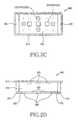
- FIGS. 2C and 2Dare respectively a front view and a side view of the sensor unit of the apparatus illustrated in FIG. 1 , which includes an optical sensor, according to another exemplary embodiment of the present invention
- FIG. 2Eis a side view of the sensor unit of the apparatus illustrated in FIG. 1 , which is put on a wrist, of a user, according to an exemplary embodiment of the present invention
- FIG. 3is a side view of an apparatus for cufflessly and non-invasively measuring blood pressure at a person's wrist according to an exemplary embodiment of the present invention
- FIG. 4is a conceptual diagram of a blood pressure measurement apparatus according to an exemplary embodiment of the present invention.
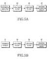
- FIGS. 5A , 5 B, and 5 Care respective circuit diagrams of an analog signal processing unit for processing signals from a pressure sensor, an infrared sensor, and an electrocardiogram (ECG) sensor according to an exemplary embodiment of the present invention
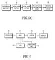
- FIG. 6is a circuit diagram of a controller including an input unit, a state display unit, and a display unit according to an exemplary embodiment of the present invention
- FIG. 7is a flowchart of a blood pressure measuring method according to an exemplary embodiment of the present invention.
- FIG. 8Ais a flowchart of a blood pressure measuring method according to an exemplary embodiment of the present invention.
- FIG. 8Bis a graph of an ECG signal and four pulse waveforms acquired through a clinical demonstration using a device for detecting a blood pressure value of a radial artery according to an exemplary embodiment of the present invention.
- FIGS. 9A , 9 B, and 9 Care scatter graphs of the lowest blood pressure value, the highest blood pressure value, and a pulse pressure value calculated using a calculation algorithm and actual values obtained from a clinical demonstration according to an exemplary embodiment of the present invention.
- wound blood pressurerefers to a measurement made in the region of the wrist. It should also be understood that the forearm could also be considered as being within such a region.
- FIG. 1is a perspective view of an apparatus for cufflessly and non-invasively measuring wrist blood pressure according to an exemplary embodiment of the present invention.
- the reference numeral 100denotes the total configuration of a portable continuous blood pressure measurement apparatus 300 according to an exemplary embodiment of the present invention.
- the non-invasive continuous blood pressure measurement apparatus 300adapted for arrangement on a wrist region of a user, and the apparatus 300 is typically driven via a measurement button 101 .
- a normal or abnormal operation stateis displayed by a state display Light Emitting Diode (LED) 107 .
- Continuous blood pressure measured using the apparatus 300is displayed by a display unit 109 of the apparatus 300 .
- LEDLight Emitting Diode
- Signals measured using the apparatus 300are a pulse wave signal, an infrared signal for measuring light intensity through incidence and reflection thereof, and an ECG signal, and in order to measure the ECG, the ECG measurement unit 201 measures an ECG of a user via a finger arranged thereon.
- a pressure and positionare adjusted using a wristband 113 of the apparatus 300 .
- the continuous blood pressure measured using the apparatus 300can be transmitted to a cellular phone or other communication device via a communication terminal 150 .
- the apparatus 300is switched to a measurement mode by pushing the measurement button 101 , which in this case is arranged in the upper right side of the apparatus 300 .
- a sensor unit ( 200 shown in FIG. 2 )is typically disposed near a radial artery region ( 350 a shown in FIG. 3 ) of a wrist 350 w , and the apparatus 300 is adapted for arrangement around or in the region of the wrist 350 w of the user using the wristband 113 of the apparatus 300 .
- the stable pulse waveis measured by adjusting pressure applied to the sensor unit ( 200 shown in FIG. 2 ).
- An ECG signalis measured by contact of a finger of the other hand, which is free from the apparatus 300 , with an ECG sensor 201 of the apparatus 300 .
- the measured pulse wave and ECG signalare stored in a Random Access Memory (RAM) ( 455 of FIG. 4 ) included in a controller ( 450 of FIG. 4 ) of the apparatus 300 .
- RAMRandom Access Memory
- FIG. 2shows two exemplary types of the sensor unit 200 of a continuous blood pressure measurement apparatus according to an exemplary embodiment of the present invention.
- FIGS. 2A and 2Brespectively illustrate a front view and a side view of the sensor unit 200 of the apparatus 300 illustrated in FIG. 1 according to an exemplary embodiment of the present invention, wherein the sensor unit includes a pressure sensor and an ECG sensor
- FIGS. 2C and 2Drespectively show a front view and a side view of the sensor unit 200 of the apparatus illustrated in FIG. 1 , which includes an optical sensor, according to another exemplary embodiment of the present invention, in which the sensor unit includes a pressure sensor, an ECG sensor, and an optical sensor.
- the sensor unit 200typically includes more than one pressure sensor 203 , a Printed Circuit Board (PCB) 210 to which the pressure sensors 203 are arranged, a gel type epoxy processed unit 220 that typically surrounds the sensors 203 and the PCB 210 , and a portion filled with gel 230 .
- Each pressure sensor 203 used in the present inventionconverts a pressure signal to an electrical signal and measures a pressure of blood flowing through a blood vessel, which is affected to the blood vessel, by being put on a radial artery.
- the more than one pressure sensors 203are arranged on the PCB 210 , and in order to prevent the gel of a portion to which pressure of the pressure sensors 203 in a vessel of the sensor unit 200 is applied from leaking out and changing the overall the density of the gel 230 in the vessel of the sensor unit 200 , the gel 230 of a portion of the sensor unit 200 touched to the wrist 350 w of the user is processed by the epoxy processed unit 220 . Since the gel 230 is used as a transmitter for transmitting a pulse wave signal, a pulse wave signal transmitted to each pressure sensor 203 varies according to density and a configuration of the gel 230 .
- a pulse wave signal transmitted to each pressure sensor 203varies according to an angle and pressure achieved between the radial artery region ( 350 a of FIG. 3 ) of the user and the sensor unit 200 , and the magnitude of each pulse wave signal output from the more than one pressure sensors 203 varies according to an amount of pressure applied to the wrist 350 w .
- This variation output by the more than one pressure sensorsis used to correct the magnitude of a detected pulse wave to absolute pressure, the absolute pressure is processed by a calculation algorithm, and a calculated signal is used for continuous blood pressure analysis.
- the sensor unit 200 for selecting a correct position of an artery and extracting a clear pulse wave signalpreferably typically includes at least one pressure sensor 203 , and outputs such pressure sensors 203 , an ECG signal detected from an electrode installed in a wrist strap, and a pulse wave signal can be used for accurate and highly repeatable continuous blood pressure analysis.
- the sensor unit 200includes an ECG sensor 201 , a plurality of infrared sensors 202 , a plurality of pressure sensors 203 , a PCB 210 to which the pressure sensors 203 are fixed, a gel type epoxy processed unit 220 surrounding the infrared sensors 202 .
- the ECG sensor 201detects an ECG signal indicating electrical activity of a heart and transmits the ECG signal to an analog signal processing unit ( 411 shown in FIG. 4 ).
- an analog signal processing unit411 shown in FIG. 4 .
- the ECG sensor 201detects an ECG signal indicating electrical activity of a heart and transmits the ECG signal to an analog signal processing unit ( 411 shown in FIG. 4 ).
- an analog signal processing unit411 shown in FIG. 4 .
- two additional electrodesare typically used in a strap region.
- two electrodes in the sensor unit 200 and the electrode ( 201 of FIG. 1 ) located in the outside of the apparatus 300are used to acquire the ECG signal.
- the infrared sensor 202typically includes a photo diode and an LED, and light emitted by the LED is multiply diffused through the skin, subcutaneous fat, muscles, and a radial artery around the wrist 350 w of the user and received by the photo diode, generating an analog output signal.
- the infrared sensors 202 of the sensor unit 200are typically located around a group of the pressure sensors 203 , and an output signal of each infrared sensor 202 is processed by a calculation program of the controller ( 450 shown in FIG. 4 ), forming a vector component.
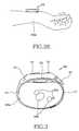
- FIG. 2Eis a side view of a sensor unit of the apparatus 300 illustrated in FIG. 1 , which is put on a wrist of a user, according to an exemplary embodiment of the present invention.
- FIG. 3is a side view of an apparatus for cufflessly and non-invasively measuring wrist blood pressure according to an exemplary embodiment of the present invention.
- FIG. 3shows an exemplary configuration of the continuous blood pressure measurement apparatus and includes the configuration illustrated in FIG. 1 .
- the configuration of the apparatuswill now be described.
- the non-invasive continuous blood pressure measurement apparatus 300is put on around the wrist region 350 w of the user and operated using the measurement button 101 , and a normal or abnormal operating state is displayed by the status display LED 107 .
- Continuous blood pressure that is measured using the apparatus 300is displayed by the display unit 109 of the apparatus 300 .
- Signals measured using the apparatus 300are a pulse wave signal, an infrared signal for measuring light intensity through incidence and reflection thereof, and an ECG signal, and in order to measure the ECG, the user 350 typically arranges a finger on the ECG sensor unit 201 .
- pressure and position of the sensor unit 200 applied to the artery region 350 a passing through a radial bone 350 b of the wrist 350 w of the userare adjusted using the wristband 113 .
- the continuous blood pressure measured using the apparatus 300can be transmitted via the terminal 150 of a communication device in order to communicate with an external device ( 470 shown in FIG. 4 ).
- FIG. 4is a conceptual diagram of a blood pressure measurement apparatus according to an exemplary embodiment of the present invention.
- a pulse wave signalis measured using the ECG sensor 201 , at least one infrared sensor 202 for measuring a correct pulse wave signal, and at least one pressure sensor 203 from the operand 350 corresponding to the user.
- An ECG signal measured using the ECG sensor 201is filtered and amplified by the analog signal processing unit corresponding to an SC 1 411 .
- the analog signal processed ECG signalis then input to an analog input terminal of an Analog/Digital (A/D) converter 451 of the controller 450 , converted to a digital signal, and stored in the RAM 455 .
- A/DAnalog/Digital
- Each infrared sensor signalwhich is measured using the at least one infrared sensor 202 , is filtered and amplified by an analog signal processing unit corresponding to an SC 2 413 .
- This analog signal processed infrared sensor signalis input to the analog input terminal of the A/D converter 451 of the controller 450 , converted to a digital signal, digital signal processed by a Digital Signal Processor (DSP) 453 using a position and depth analysis program stored in a Read Only Memory (ROM) 457 , and displayed on the display unit 109 .
- DSPDigital Signal Processor
- the infrared sensor signalis used to compensate individual conditions varying according to a user, such as a measured position and the depth of an artery.
- a pulse wave signal measured using a plurality of pressure sensors 203is filtered and amplified by an analog signal processing unit corresponding to an SC 3 415 , input to the analog input terminal of the A/D converter 451 , displayed on the display unit 109 , and stored in the RAM 455 .
- the ECG signal and the pulse wave signal stored in the RAM 455is a digital signal processed by the DSP 453 using a continuous blood pressure analysis program stored in the ROM 457 , and the analysis result is displayed on the display unit 109 and stored in a flash memory 459 .
- the stored continuous blood pressure result valuecan be transmitted to an external device 470 , such as a Personal Computer (PC) or a Personal Digital Assistant (PDA), or a server, by using the interface terminal 150 , such as an external communication terminal.
- an external device 470such as a Personal Computer (PC) or a Personal Digital Assistant (PDA), or a server
- the interface terminal 150such as an external communication terminal.
- external inputs 103 and 105are used.
- FIGS. 5A , 5 B, and 5 Care respective diagrams of circuits for processing analog signals measured from the pressure sensor 203 , the infrared sensor 202 , and the ECG sensor 201 used in the continuous blood pressure measurement apparatus 300 according to an exemplary embodiment of the present invention.
- FIG. 5Ais a circuit diagram of a unit for processing an analog signal from a pressure sensor according to an exemplary embodiment of the present invention, showing a circuit taking charge of analog signal processing of a pulse wave signal measured by the pressure sensor 203 of the continuous blood pressure and artery elasticity measurement apparatus 300 .
- a pulse wave signal having two polarities measured by the pressure sensor ( 203 of FIG. 4 ) from the user's wrist 350 wis input to the input terminal of the analog signal processing unit ( 415 of FIG. 4 ).
- a signal unnecessary to analyze continuous blood pressure and artery elasticityis removed using a High Pass Filter (HPF) 23 , whose cut-off frequency is 0.1 Hz for cutting off low-band noise lower than 0.1 Hz, and a 4 th order Low Pass Filter (LPF) 25 , whose cut-off frequency is 10 Hz for cutting off high-band noise higher than 10 Hz.
- HPFHigh Pass Filter
- LPFLow Pass Filter
- the noise-cancelled signalis secondary amplified by a reverse amplification circuit 27 not to be saturated higher than a supplied voltage and is input to the analog input terminal of the A/D converter ( 451 of FIG. 4 ) of the controller ( 450 of FIG. 4 ) in order to be converted to a digital signal.
- FIG. 5Bis a circuit diagram of a unit for processing an analog signal from an infrared sensor according to an exemplary embodiment of the present invention, showing a circuit taking charge of analog signal processing of an infrared sensor signal measured by the infrared sensor ( 202 shown in FIG. 4 ) of the continuous blood pressure measurement apparatus 300 .
- a signal unnecessary to analyze artery position informationis removed using an HPF 33 whose cut-off frequency is 0.1 Hz for cutting off low-band noise lower than 0.1 Hz and a 4 th order LPF 35 whose cut-off frequency is 10 Hz for cutting off high-band noise higher than 10 Hz.
- the noise-cancelled signalis secondary amplified by a reverse amplification circuit 37 not to be saturated higher than a supplied voltage and is input to the analog input terminal of the A/D converter ( 451 of FIG. 4 ) of the controller ( 450 of FIG. 4 ) in order to be converted to a digital signal.
- FIG. 5Cis a circuit diagram of a unit for processing an analog signal from an ECG sensor according to another exemplary embodiment of the present invention, showing a circuit taking charge of analog signal processing of an ECG signal measured by the ECG sensor ( 201 of FIG. 4 ) of the continuous blood pressure measurement apparatus 300 .
- an ECG signalis a signal shown by converting an activity potential of a heart measured by three electrodes, i.e. the ECG sensors ( 201 of FIG. 4 ), to a voltage, and if a Common Mode Rejection Ratio (CMRR) indicating a ratio of common mode noise input through the human body increases, the common mode noise is removed using a differential amplifier 41 , and only a potential difference between a + electrode and a ⁇ electrode is amplified.
- CMRRCommon Mode Rejection Ratio
- a signal unnecessary to analyze continuous blood pressureis removed using an HPF 43 whose cut-off frequency is 1 Hz for cutting off low-band noise lower than 1 Hz, a 4 th order LPF 45 whose cut-off frequency is 30 Hz for cutting off high-band noise higher than 30 Hz, and a notch filter 47 for removing noise due to the general-use frequency (50/60 Hz) input through the electrodes.
- the noise-cancelled signalis secondary amplified by a reverse amplification circuit 49 not to be saturated higher than a supplied voltage and is input to the analog input terminal of the A/D converter ( 451 of FIG. 4 ) of the controller ( 450 of FIG. 4 ) in order to be converted to a digital signal.
- FIG. 6is a circuit diagram of the controller 450 including an input unit, the state display unit 107 , and a display unit 111 in the continuous blood pressure measurement apparatus 300 according to another exemplary embodiment of the present invention.
- the controller 450(shown in FIG. 4 ) in the continuous blood pressure measurement apparatus 300 according to the current exemplary embodiment that includes the display unit 109 of the apparatus 300 , the measurement button 101 for measuring measurement in the apparatus 300 , the measurement buttons 103 and 105 for external inputs, the state display LED 107 displaying an operating state of the apparatus 300 , and the communication terminal 150 for interfacing with the external device 470 , such as a PC or PDA.
- the external device 470such as a PC or PDA.
- Analog signal processed pulse wave signal, infrared sensor signal, and ECG signalare input to the analog input terminal of the A/D converter ( 451 shown in FIG. 4 ) and converted to digital signals.
- the pulse wave signalis displayed on the display unit 109 and stored in the RAM 455 of the controller 450 (shown in FIG. 4 ).
- a continuous blood pressure valueis deduced using the continuous blood pressure analysis program stored in the ROM ( 457 in FIG. 4 ) of the controller 450 and displayed on the display unit 109 .
- Calculated result datais stored in the flash memory 459 of the controller 450 and can be transmitted to the external device 470 , such as a cellular phone, via the communication terminal 150 .
- the controller 450calculates data on an 8-bit basis, has a 16-channel analog input terminal, selects a signal of which an input exists using a multiplexer (MUX) 71 , and outputs the selected signal via an output circuit.
- the equipped A/D converter 451has 10-bit resolution, and since the controller 450 includes the external communication terminal 150 (shown in FIG. 1 ), the controller 450 can interface with the external device 470 , such as a PC or PDA, without an additional communication interface.
- the controller 450also can store the calculation program using the ROM ( 457 of FIG. 4 ).
- controller 450can process input data by itself, memory mapping is necessary to expand data storage memory and connect a display Liquid Crystal Display (LCD).
- LCDLiquid Crystal Display
- address and data busesare preferably be used.
- an AVRuses an address (16 bits)/data (8 bits) method and uses the same pins as lower address data, data and an address are divided using a latch 73 .
- a data storage memory and an LCDare memory mapped with each other, and in order to generate a chip selecting signal, a digital signal is converted to an analog signal using a decoder 75 .
- the controller 450forms a vector component by mixing more than infrared sensor signals using the calculation program stored in the ROM 457 , searches for correct position and depth information of an artery using the formed vector component, and can show a continuous blood pressure analysis result by comparing and analyzing a measured pulse wave signal and an ECG signal.
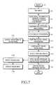
- FIG. 7is a flowchart illustrating exemplary steps of a blood pressure measuring method in the continuous blood pressure measurement apparatus 300 according to an exemplary embodiment of the present invention.
- a signal generated due to the measurement button ( 101 of FIG. 1 )is input to the external inputs ( 103 and 105 shown in FIG. 4 ) of the controller ( 450 shown in FIG. 4 ) in step F 3 .
- the controller450 shown in FIG. 4
- step F 3By acquiring artery position and depth information using at least one infrared sensor ( 202 shown in FIG. 4 ), measuring a pulse wave signal using the pressure sensor ( 203 shown in FIG. 4 ), and measuring an ECG signal using the ECG sensor ( 201 shown in FIG.
- an analog signal processorperforms processes the ECG signal, the infrared sensor signal, and the pulse wave signal in step F 7 .
- Each one of the analog signal processed ECG signal, infrared sensor signal, and pulse wave signalis input to the analog input terminal of the A/D converter ( 451 shown in FIG. 4 ) of the controller ( 450 shown in FIG. 4 ) and converted to a digital signal in step F 9 .
- a digital LPFis applied to the radial pulse wave signal converted to the digital signal, and after trends are removed in step F 11 , the radial pulse wave signal is displayed in step F 12 .
- step F 13By calculating a non-distorted radial artery pressure value from the signal processed radial pulse wave signal using position and depth information from the infrared sensor signal and an R-peak timing of the ECG signal to be described later, variation due to a pressure difference is compensated in step F 13 , feature points are detected from the compensated radial pulse wave signal in step F 15 , and an algorithm for calculating a brachial blood pressure value is applied based on the feature points in step F 17 .
- a per-minute pulse rateis calculated from the detection of the feature points of the pulse wave in step F 16 , the calculated pulse rate is displayed in step F 19 , and a systolic blood pressure value and a diastolic blood pressure value calculated based on the algorithm are displayed in step F 21 .
- the algorithm calculation processwill be described with reference to FIG. 8A .
- FIG. 8Ais a flowchart of a calculation process of the continuous blood pressure measuring algorithm according to an exemplary embodiment of the present invention.
- an R-peakis detected from a P-QRS-T waveform indicating one period of electric activity of a heart using an ECG signal.
- the R-peakdenotes a de-polarization timing of the left ventricle of the heart.
- a beginning point, the highest point, and a notch pointare detected from respective pulse wave signals.
- a pulse wave signal using infraredis used to compensate the detection of the highest point.
- the calculation process using the algorithmends, and the highest blood pressure value and the lowest blood pressure value are then displayed in step D 11 .
- FIG. 8Bis a graph of an ECG signal E 1 and four pulse waveforms E 2 through E 5 acquired through a clinical demonstration using a device for detecting a blood pressure value of a radial artery according to an exemplary embodiment of the present invention.
- FIG. 8Bfeature points detected by using the blood pressure calculation algorithm described in FIG. 7 are shown.
- an R-peak G 1is detected from a P-QRS-T waveform indicating one period of electric activity of a heart from the ECG signal E 1 .
- the R-peak G 1denotes a de-polarization timing of the left ventricle of a heart.
- a beginning point G 2 , the highest point G 4 , and a notch point G 3are detected from the respective pulse wave signals E 2 through E 5 .
- FIGS. 9A , 9 B, and 9 Care scatter graphs of the lowest blood pressure value, the highest blood pressure value, and a pulse pressure value calculated using the calculation algorithm and actual values obtained from a clinical demonstration according to an exemplary embodiment of the present invention.
- the showing scatter graphs of representative variablesare deduced by applying the algorithm according to an exemplary embodiment of the present invention to the highest blood pressure value and the lowest blood pressure value invasively detected using catheters and the ECG signal E 1 and the pulse waveforms E 2 through E 5 detected by a continuous blood pressure measurement apparatus for clinical validation.
- FIG. 9Ashows a scatter graph and a linear regression line of a time value from the R-peak G 1 , which is a variable showing high correlation with the highest blood pressure value among the extracted variables, to the pulse wave highest point G 4
- FIG. 9Bshows a scatter graph and a linear regression line of a time value from the pulse wave highest point G 4 , which is a variable showing high correlation with the lowest blood pressure value among the extracted variables, to the pulse wave notch point G 3
- FIG. 9Ashows a scatter graph and a linear regression line of a
- 9Cshows a scatter graph and a linear regression line of an absolute value of a compensated pulse pressure value, which is used for compensation as an absolute pressure value by setting a criterion of pressure applied to a wrist region using magnitude differences between at least one of the pulse wave signals E 2 through E 5 , and an area value from pulse wave beginning point G 2 to the pulse wave notch point G 3 .
- a time difference between an R-peak of an ECG signal and the highest point of a pulse wavehas strong correlation with the highest blood pressure
- the time from the highest point of the pulse wave to a notch pointhas strong correlation with the lowest blood pressure. Since these values are expressed by time, these values are not concerned with measured pressure.
- a direct line connecting a beginning point of the pulse wave and the notch point and an area between a waveform of the pulse wave and a direct line connecting a beginning point of the pulse wave and the notch pointhas strong correlation with pulse pressure indicating a difference between the highest blood pressure and the lowest blood pressure.
- the three correlation expressionsare deduced from a clinical demonstration, and the highest blood pressure, the lowest blood pressure, and mean blood pressure can be obtained from two of the three correlation expressions or a set of any of them.
- the highest and lowest blood pressure valuescan be transmitted to an external device, such as a nurse's station, network, health monitoring system, etc. periodically and or when the values exceed a predetermined threshold.
- the thresholdcould be either higher or lower than a preset range.
- a non-invasive continuous blood pressure measurement apparatuswhich can be easily used on a person and have portability, and a method thereof can be applied to the development of a system for considerably improving the accuracy of conventional blood pressure measurement apparatuses that do not use a cuff and show quantitative values of accurate blood pressure considering various measurement conditions. Accordingly, the apparatus and method can be positively used for early diagnosis of heart/blood related diseases.
- the apparatuscan be a requisite health care device in a well-being society. While the invention has been shown and described with reference to a certain preferred exemplary embodiments thereof, it will be understood by those skilled in the art that various changes in form and details may be made therein without departing from the spirit of the invention and the scope of the appended claims.
Landscapes
- Health & Medical Sciences (AREA)
- Life Sciences & Earth Sciences (AREA)
- Cardiology (AREA)
- Biomedical Technology (AREA)
- Medical Informatics (AREA)
- Biophysics (AREA)
- Pathology (AREA)
- Engineering & Computer Science (AREA)
- Veterinary Medicine (AREA)
- Heart & Thoracic Surgery (AREA)
- Physics & Mathematics (AREA)
- Molecular Biology (AREA)
- Surgery (AREA)
- Animal Behavior & Ethology (AREA)
- General Health & Medical Sciences (AREA)
- Public Health (AREA)
- Physiology (AREA)
- Vascular Medicine (AREA)
- Measuring Pulse, Heart Rate, Blood Pressure Or Blood Flow (AREA)
Abstract
Description
Claims (11)
Applications Claiming Priority (3)
| Application Number | Priority Date | Filing Date | Title |
|---|---|---|---|
| KR10-2007-0024163 | 2007-03-12 | ||
| KR24163/2007 | 2007-03-12 | ||
| KR1020070024163AKR100871230B1 (en) | 2007-03-12 | 2007-03-12 | Non-invasive, non-invasive wrist blood pressure measurement method and apparatus that interoperate with a communication device |
Publications (2)
| Publication Number | Publication Date |
|---|---|
| US20080228089A1 US20080228089A1 (en) | 2008-09-18 |
| US8086301B2true US8086301B2 (en) | 2011-12-27 |
Family
ID=39493531
Family Applications (1)
| Application Number | Title | Priority Date | Filing Date |
|---|---|---|---|
| US12/075,377Expired - Fee RelatedUS8086301B2 (en) | 2007-03-12 | 2008-03-11 | Method and apparatus for cufflessly and non-invasively measuring wrist blood pressure in association with communication device |
Country Status (4)
| Country | Link |
|---|---|
| US (1) | US8086301B2 (en) |
| EP (1) | EP1970000B1 (en) |
| KR (1) | KR100871230B1 (en) |
| CN (1) | CN101264011B (en) |
Cited By (18)
| Publication number | Priority date | Publication date | Assignee | Title |
|---|---|---|---|---|
| US20160235325A1 (en)* | 2015-02-17 | 2016-08-18 | Chang-An Chou | Cardiovascular monitoring device |
| US9636023B2 (en) | 2014-03-12 | 2017-05-02 | John M. Geesbreght | Portable rapid vital sign apparatus and method |
| CN107106054A (en)* | 2014-09-08 | 2017-08-29 | 苹果公司 | Blood Pressure Monitoring Using a Multifunctional Wrist-Worn Device |
| EP3241494A1 (en) | 2016-05-04 | 2017-11-08 | Valtronic Technologies (Holding) SA | Device for detecting or monitoring bioelectrical parameters |
| US10178975B2 (en) | 2015-03-19 | 2019-01-15 | Htc Corporation | Detecting system and mobile electronic apparatus, and method for detecting physiological characteristic thereof method thereof |
| US10444067B2 (en) | 2014-10-31 | 2019-10-15 | Industrial Technology Research Institute | Optical sensing apparatus and measuring method thereof |
| US10448848B2 (en) | 2015-10-06 | 2019-10-22 | Samsung Electronics Co., Ltd. | Apparatus and method for measuring bioinformation |
| US10660532B2 (en) | 2016-10-25 | 2020-05-26 | Samsung Electronics Co., Ltd. | Blood pressure measurement apparatus, portable pressure measurement apparatus, and calibration method for blood pressure measurement apparatus |
| US10849555B1 (en) | 2015-09-29 | 2020-12-01 | Apple Inc. | Devices and systems for correcting errors in blood pressure measurements |
| US11478606B1 (en) | 2020-01-08 | 2022-10-25 | New Heights Energy, LLC | Wearable devices and methods for providing therapy to a user and/or for measuring physiological parameters of the user |
| US11490852B1 (en) | 2021-08-09 | 2022-11-08 | hemal b kurani | Wearable device for detecting microorganisms, sterilizing pathogens, and environmental monitoring |
| US11660009B2 (en) | 2019-07-11 | 2023-05-30 | Samsung Electronics Co., Ltd. | Apparatus and method for estimating bio-information |
| US11911134B2 (en) | 2020-07-23 | 2024-02-27 | Samsung Electronics Co., Ltd. | Apparatus and method for estimating bio-information |
| US12023153B2 (en) | 2017-02-13 | 2024-07-02 | Apple Inc. | Light restriction designs in optical sensing applications having shared windows |
| US12064224B2 (en) | 2017-09-26 | 2024-08-20 | Apple Inc. | Concentric architecture for optical sensing |
| US12072288B2 (en) | 2014-09-02 | 2024-08-27 | Apple Inc. | Multiple light paths architecture and obscuration methods for signal and perfusion index optimization |
| US12296108B2 (en) | 2022-03-10 | 2025-05-13 | Therabody, Inc. | Device for providing multiple types of therapy to a user |
| US12343170B2 (en) | 2018-08-01 | 2025-07-01 | Samsung Electronics Co., Ltd. | Bio-information measuring apparatus and bio-information measuring method |
Families Citing this family (89)
| Publication number | Priority date | Publication date | Assignee | Title |
|---|---|---|---|---|
| KR100732600B1 (en)* | 2005-07-21 | 2007-06-27 | 삼성전자주식회사 | Portable device having biosignal-measuring instrument |
| US20080221930A1 (en) | 2007-03-09 | 2008-09-11 | Spacelabs Medical, Inc. | Health data collection tool |
| KR101366809B1 (en)* | 2007-09-06 | 2014-02-24 | 삼성전자주식회사 | Blood pressure measuring apparatus and method of measuring blood pressure |
| US8398556B2 (en)* | 2008-06-30 | 2013-03-19 | Covidien Lp | Systems and methods for non-invasive continuous blood pressure determination |
| US9044146B2 (en)* | 2008-10-06 | 2015-06-02 | Korea Institute Of Oriental Medicine | Arm-fastening device for pulse diagnosis, pulse sensor, pulse diagnosis apparatus comprising the device and sensor, and method for manufacturing pulse sensor |
| KR20100060141A (en)* | 2008-11-27 | 2010-06-07 | 삼성전자주식회사 | Portable device for measuring blood pressure and method thereof |
| US9604020B2 (en) | 2009-10-16 | 2017-03-28 | Spacelabs Healthcare Llc | Integrated, extendable anesthesia system |
| CN102667423B (en) | 2009-10-16 | 2016-06-08 | 太空实验室健康护理有限公司 | light enhanced flow tube |
| EP3503115A3 (en) | 2010-03-21 | 2019-10-23 | Spacelabs Healthcare LLC | Patient monitoring system |
| CN101933801B (en)* | 2010-08-31 | 2013-06-19 | 天津九安医疗电子股份有限公司 | Digital manometer |
| WO2012068567A1 (en) | 2010-11-19 | 2012-05-24 | Spacelabs Healthcare, Llc | Dual serial bus interface |
| CN102106725B (en)* | 2011-03-02 | 2013-03-27 | 哈尔滨工业大学 | Traditional Chinese medical pulse condition sensor merging photoelectricity and pressure |
| US9629566B2 (en)* | 2011-03-11 | 2017-04-25 | Spacelabs Healthcare Llc | Methods and systems to determine multi-parameter managed alarm hierarchy during patient monitoring |
| CN103517669B (en)* | 2011-03-11 | 2016-04-20 | 太空实验室健康护理有限公司 | The method and system of multiparameter administrative alert grade is determined during patient monitoring |
| GB201111138D0 (en) | 2011-06-30 | 2011-08-17 | Leman Micro Devices Uk Ltd | Personal health data collection |
| CN102293642A (en)* | 2011-08-04 | 2011-12-28 | 浙江富美家健康科技有限公司 | Blood pressure measuring method and blood-pressure meter implementing method |
| CN102429649B (en)* | 2011-12-14 | 2014-02-19 | 中国航天员科研训练中心 | Continuous Blood Pressure Measurement Device |
| CN102397064B (en)* | 2011-12-14 | 2014-02-19 | 中国航天员科研训练中心 | Continuous Blood Pressure Measurement Device |
| CN102551690B (en)* | 2011-12-29 | 2013-10-09 | 乐普(北京)医疗器械股份有限公司 | Adaptive analysis method of human body signal |
| US9204809B2 (en)* | 2012-02-01 | 2015-12-08 | Hong Kong Applied Science and Technology Research Institute Company Limited | Blood pressure measuring device and method of calibrating thereof |
| KR101288391B1 (en) | 2012-03-08 | 2013-07-22 | 주식회사 유메딕스 | Blood pressure measuring method and blood pressure measuring device accordingly |
| WO2014037874A1 (en)* | 2012-09-10 | 2014-03-13 | Koninklijke Philips N.V. | Device and method to improve dependability of physiological parameter measurements |
| US20140196131A1 (en)* | 2013-01-07 | 2014-07-10 | Salutron, Inc. | User authentication based on a wrist vein pattern |
| JP2016509868A (en)* | 2013-02-13 | 2016-04-04 | ルマン・ミクロ・デバイシズ・ソシエテ・アノニムLeman Micro Devices Sa | Noninvasive blood analysis |
| FI20136306L (en)* | 2013-03-22 | 2014-09-23 | Murata Manufacturing Co | Improved blood pressure monitoring method |
| FI124971B (en)* | 2013-03-22 | 2015-04-15 | Murata Manufacturing Co | Blood pressure measuring device and blood pressure calibration method |
| US10987026B2 (en) | 2013-05-30 | 2021-04-27 | Spacelabs Healthcare Llc | Capnography module with automatic switching between mainstream and sidestream monitoring |
| US9626478B2 (en) | 2013-10-24 | 2017-04-18 | Logitech Europe, S.A. | System and method for tracking biological age over time based upon heart rate variability |
| US20150116125A1 (en)* | 2013-10-24 | 2015-04-30 | JayBird LLC | Wristband with removable activity monitoring device |
| US9314172B2 (en) | 2013-10-24 | 2016-04-19 | JayBird LLC | System and method for providing a training load schedule for peak performance positioning |
| US9622685B2 (en) | 2013-10-24 | 2017-04-18 | Logitech Europe, S.A. | System and method for providing a training load schedule for peak performance positioning using earphones with biometric sensors |
| US9864843B2 (en) | 2013-10-24 | 2018-01-09 | Logitech Europe S.A. | System and method for identifying performance days |
| US9848828B2 (en) | 2013-10-24 | 2017-12-26 | Logitech Europe, S.A. | System and method for identifying fatigue sources |
| US10078734B2 (en) | 2013-10-24 | 2018-09-18 | Logitech Europe, S.A. | System and method for identifying performance days using earphones with biometric sensors |
| USD777186S1 (en) | 2014-12-24 | 2017-01-24 | Logitech Europe, S.A. | Display screen or portion thereof with a graphical user interface |
| US20150230754A1 (en)* | 2014-02-14 | 2015-08-20 | Kevin Willis | Restraint System |
| US20150250398A1 (en)* | 2014-03-06 | 2015-09-10 | Medsense Inc. | Sensor module for simultaneously measuring ecg and pulse signal |
| US9931076B2 (en)* | 2014-06-18 | 2018-04-03 | Hong Kong Applied Science and Technology Research Institute Company Limited | Method and device for tonometric blood pressure measurement |
| KR101646529B1 (en)* | 2014-07-10 | 2016-08-08 | 연세대학교 산학협력단 | Apparatus and method for automatic detection of arterial blood pressure |
| US10092197B2 (en)* | 2014-08-27 | 2018-10-09 | Apple Inc. | Reflective surfaces for PPG signal detection |
| KR102299361B1 (en) | 2014-09-03 | 2021-09-07 | 삼성전자주식회사 | Apparatus and method for monitoring blood pressure, wearable device having function of blood pressure monitoring |
| US10694960B2 (en) | 2014-09-29 | 2020-06-30 | Microsoft Technology Licensing, Llc | Wearable pulse pressure wave sensing device |
| US9848825B2 (en)* | 2014-09-29 | 2017-12-26 | Microsoft Technology Licensing, Llc | Wearable sensing band |
| US9849538B2 (en) | 2014-12-24 | 2017-12-26 | Logitech Europe, S.A. | Watertight welding methods and components |
| KR102411658B1 (en) | 2015-01-15 | 2022-06-21 | 삼성전자주식회사 | Apparatus for detecting information of the living body |
| CN104622440B (en)* | 2015-02-09 | 2018-02-09 | 中国科学院深圳先进技术研究院 | The method and device of punctuate during a kind of extraction pulse wave |
| KR102384225B1 (en)* | 2015-03-06 | 2022-04-07 | 삼성전자주식회사 | System and method for sensing blood pressure |
| RU2703639C2 (en)* | 2015-03-13 | 2019-10-21 | Конинклейке Филипс Н.В. | Device for photoplethysmography |
| KR20160115017A (en)* | 2015-03-25 | 2016-10-06 | 삼성전자주식회사 | Apparatus and method for sensing information of the living body |
| USD784961S1 (en) | 2015-06-05 | 2017-04-25 | Logitech Europe, S.A. | Ear cushion |
| JP6510913B2 (en) | 2015-07-01 | 2019-05-08 | 浜松ホトニクス株式会社 | Blood pressure ratio calculation device, blood pressure ratio calculation method, blood pressure ratio calculation program, and recording medium for recording the program |
| US9913591B2 (en)* | 2015-07-02 | 2018-03-13 | Verily Life Sciences Llc | Wrist-mounted device with integrated electronics |
| US9729953B2 (en) | 2015-07-24 | 2017-08-08 | Logitech Europe S.A. | Wearable earbuds having a reduced tip dimension |
| KR102434701B1 (en) | 2015-09-01 | 2022-08-22 | 삼성전자주식회사 | Apparatus and method for acquiring bio- information and apparatus for detecting bio- information |
| US10537284B1 (en) | 2015-09-30 | 2020-01-21 | Apple Inc. | Enhanced sensor signal collection and reflection of reflected and/or scattered light |
| US9743745B2 (en) | 2015-10-02 | 2017-08-29 | Logitech Europe S.A. | Optimized cord clip |
| US10117015B2 (en) | 2015-10-20 | 2018-10-30 | Logitech Europe, S.A. | Earphones optimized for users with small ear anatomy |
| US10559220B2 (en) | 2015-10-30 | 2020-02-11 | Logitech Europe, S.A. | Systems and methods for creating a neural network to provide personalized recommendations using activity monitoring devices with biometric sensors |
| US10292606B2 (en) | 2015-11-05 | 2019-05-21 | Logitech Europe, S.A. | System and method for determining performance capacity |
| US9986323B2 (en) | 2015-11-19 | 2018-05-29 | Logitech Europe, S.A. | Earphones with attachable expansion pack |
| CN108348178B (en) | 2015-11-26 | 2021-01-05 | 华为技术有限公司 | Blood pressure parameter detection method and user terminal |
| US10129628B2 (en) | 2016-02-01 | 2018-11-13 | Logitech Europe, S.A. | Systems, methods and devices for providing an exertion recommendation based on performance capacity |
| US10420474B2 (en) | 2016-02-01 | 2019-09-24 | Logitech Europe, S.A. | Systems and methods for gathering and interpreting heart rate data from an activity monitoring device |
| US10112075B2 (en) | 2016-02-01 | 2018-10-30 | Logitech Europe, S.A. | Systems, methods and devices for providing a personalized exercise program recommendation |
| JP6172351B1 (en) | 2016-07-05 | 2017-08-02 | オムロンヘルスケア株式会社 | Sphygmomanometer |
| CN107788965A (en) | 2016-09-05 | 2018-03-13 | 京东方科技集团股份有限公司 | A kind of determination method and device of blood pressure |
| CN106419879B (en)* | 2016-09-22 | 2020-10-30 | 上海潓美医疗科技有限公司 | Blood pressure dynamic monitoring system and method based on radial artery biosensor technology |
| KR102655671B1 (en) | 2016-10-12 | 2024-04-05 | 삼성전자주식회사 | Apparatus and method for estimating bio-information |
| US10722125B2 (en)* | 2016-10-31 | 2020-07-28 | Livemetric (Medical) S.A. | Blood pressure signal acquisition using a pressure sensor array |
| WO2018082211A1 (en)* | 2016-11-02 | 2018-05-11 | 华为技术有限公司 | Smart wearable device |
| TWI653029B (en)* | 2016-12-01 | 2019-03-11 | 深禾醫學科技股份有限公司 | Pulse detection module and blood pressure measuring device therewith |
| US11000193B2 (en) | 2017-01-04 | 2021-05-11 | Livemetric (Medical) S.A. | Blood pressure measurement system using force resistive sensor array |
| KR101872395B1 (en)* | 2017-01-12 | 2018-06-28 | 주식회사 룩센테크놀러지 | Multi-channel readout signal overlap-protecting switching circuit and method thereof |
| CN108926335A (en)* | 2017-05-26 | 2018-12-04 | 深圳市玉成创新科技有限公司 | Based on pulse wave and cardiac electrical blood pressure acquisition methods and its system and device |
| EP3430991A1 (en)* | 2017-07-21 | 2019-01-23 | Koninklijke Philips N.V. | Apparatus and method for determining blood pressure of a subject |
| KR102042700B1 (en)* | 2017-11-17 | 2019-11-08 | 가천대학교 산학협력단 | System and method for estimating blood pressure based on deep learning |
| KR102580267B1 (en)* | 2018-01-18 | 2023-09-19 | 삼성전자주식회사 | Apparatus for measuring biological signal |
| KR102158498B1 (en)* | 2018-01-19 | 2020-09-22 | 한국과학기술원 | piezo-electric based blood pressure measuring apparatus using piezo-electric pulse device |
| KR102544669B1 (en) | 2018-04-12 | 2023-06-16 | 삼성전자주식회사 | Apparatus and method for measuring bio-information |
| PL425374A1 (en)* | 2018-04-26 | 2019-11-04 | Invis Spolka Z Ograniczona Odpowiedzialnoscia | Elastic measuring insert |
| US11690520B2 (en)* | 2018-06-20 | 2023-07-04 | Samsung Electronics Co., Ltd. | Apparatus and method for measuring bio-information |
| CN109157202B (en)* | 2018-09-18 | 2021-06-01 | 东北大学 | Cardiovascular disease early warning system based on multi-physiological signal deep fusion |
| KR102640331B1 (en)* | 2018-10-19 | 2024-02-26 | 삼성전자주식회사 | Apparatus and method for estimating bio-information, and apparatus for supporting bio-information estimation |
| CN118902469A (en) | 2019-06-26 | 2024-11-08 | 太空实验室健康护理有限公司 | Modifying monitored physiological data using data of body worn sensors |
| US11523766B2 (en) | 2020-06-25 | 2022-12-13 | Spacelabs Healthcare L.L.C. | Systems and methods of analyzing and displaying ambulatory ECG data |
| IL275999A (en)* | 2020-07-12 | 2022-02-01 | Cardiacsense Ltd | A measurement device for measuring physiological parameters |
| WO2022101809A1 (en)* | 2020-11-10 | 2022-05-19 | University Of Southern California | Noninvasive heart failure detection |
| US20240071617A1 (en) | 2021-01-15 | 2024-02-29 | Kyocera Corporation | Electronic device |
| CN116421162A (en)* | 2023-05-04 | 2023-07-14 | 深圳市安博健康科技有限公司 | Tension method pressure pulse wave sensor |
Citations (10)
| Publication number | Priority date | Publication date | Assignee | Title |
|---|---|---|---|---|
| US5033471A (en) | 1988-03-23 | 1991-07-23 | Colin Electronics Co., Ltd. | Method and apparatus measuring blood pressure |
| US5535753A (en)* | 1994-10-04 | 1996-07-16 | Rutgers University | Apparatus and methods for the noninvasive measurement of cardiovascular system parameters |
| US6361501B1 (en)* | 1997-08-26 | 2002-03-26 | Seiko Epson Corporation | Pulse wave diagnosing device |
| US6413223B1 (en) | 1999-06-01 | 2002-07-02 | Massachussetts Institute Of Technology | Cuffless continuous blood pressure monitor |
| US6669648B1 (en) | 1999-03-30 | 2003-12-30 | Cnsystems Medizintechnik Gmbh | Continuous non-invasive sphygmomanometer |
| WO2004019754A2 (en) | 2002-08-31 | 2004-03-11 | Youin Bio Tech Co., Ltd | Automatic blood pressure measuring instrument and method thereof |
| KR20050067651A (en) | 2003-12-29 | 2005-07-05 | 학교법인연세대학교 | Non-invasive blood pressure measuring system using volume pulse |
| JP2006149846A (en) | 2004-11-30 | 2006-06-15 | Olympus Corp | Blood vessel observation system |
| US20070021676A1 (en) | 2005-07-21 | 2007-01-25 | Samsung Electronics Co., Ltd. | Portable device having biosignal-measuring instrument |
| KR20070075515A (en) | 2006-01-13 | 2007-07-24 | (주)한별메디텍 | Non-invasive continuous blood pressure, arterial elasticity measuring device and method |
- 2007
- 2007-03-12KRKR1020070024163Apatent/KR100871230B1/ennot_activeExpired - Fee Related
- 2008
- 2008-03-11USUS12/075,377patent/US8086301B2/ennot_activeExpired - Fee Related
- 2008-03-12CNCN2008100837769Apatent/CN101264011B/ennot_activeExpired - Fee Related
- 2008-03-12EPEP08004559.4Apatent/EP1970000B1/ennot_activeCeased
Patent Citations (10)
| Publication number | Priority date | Publication date | Assignee | Title |
|---|---|---|---|---|
| US5033471A (en) | 1988-03-23 | 1991-07-23 | Colin Electronics Co., Ltd. | Method and apparatus measuring blood pressure |
| US5535753A (en)* | 1994-10-04 | 1996-07-16 | Rutgers University | Apparatus and methods for the noninvasive measurement of cardiovascular system parameters |
| US6361501B1 (en)* | 1997-08-26 | 2002-03-26 | Seiko Epson Corporation | Pulse wave diagnosing device |
| US6669648B1 (en) | 1999-03-30 | 2003-12-30 | Cnsystems Medizintechnik Gmbh | Continuous non-invasive sphygmomanometer |
| US6413223B1 (en) | 1999-06-01 | 2002-07-02 | Massachussetts Institute Of Technology | Cuffless continuous blood pressure monitor |
| WO2004019754A2 (en) | 2002-08-31 | 2004-03-11 | Youin Bio Tech Co., Ltd | Automatic blood pressure measuring instrument and method thereof |
| KR20050067651A (en) | 2003-12-29 | 2005-07-05 | 학교법인연세대학교 | Non-invasive blood pressure measuring system using volume pulse |
| JP2006149846A (en) | 2004-11-30 | 2006-06-15 | Olympus Corp | Blood vessel observation system |
| US20070021676A1 (en) | 2005-07-21 | 2007-01-25 | Samsung Electronics Co., Ltd. | Portable device having biosignal-measuring instrument |
| KR20070075515A (en) | 2006-01-13 | 2007-07-24 | (주)한별메디텍 | Non-invasive continuous blood pressure, arterial elasticity measuring device and method |
Non-Patent Citations (1)
| Title |
|---|
| Im, Jae J.; et al.; "A Study for the Development of a Noninvasive Continuous Blood Pressure Measuring System by Analyzing Radial Artery Pulse From a Wrist;" Engineering in Medicine and Biology Society; Sep. 1995; XP 010215080. |
Cited By (28)
| Publication number | Priority date | Publication date | Assignee | Title |
|---|---|---|---|---|
| US9636023B2 (en) | 2014-03-12 | 2017-05-02 | John M. Geesbreght | Portable rapid vital sign apparatus and method |
| US12072288B2 (en) | 2014-09-02 | 2024-08-27 | Apple Inc. | Multiple light paths architecture and obscuration methods for signal and perfusion index optimization |
| CN107106054A (en)* | 2014-09-08 | 2017-08-29 | 苹果公司 | Blood Pressure Monitoring Using a Multifunctional Wrist-Worn Device |
| US12220213B2 (en) | 2014-09-08 | 2025-02-11 | Apple Inc. | Blood pressure monitoring using a multi-function wrist-worn device |
| CN107106054B (en)* | 2014-09-08 | 2021-11-02 | 苹果公司 | Blood pressure monitoring with a multifunctional wrist-worn device |
| US10772512B2 (en) | 2014-09-08 | 2020-09-15 | Apple Inc. | Blood pressure monitoring using a multi-function wrist-worn device |
| US10444067B2 (en) | 2014-10-31 | 2019-10-15 | Industrial Technology Research Institute | Optical sensing apparatus and measuring method thereof |
| US20160235325A1 (en)* | 2015-02-17 | 2016-08-18 | Chang-An Chou | Cardiovascular monitoring device |
| US9782098B2 (en)* | 2015-02-17 | 2017-10-10 | MD Biomedical, Inc. | Cardiovascular monitoring device |
| US10178975B2 (en) | 2015-03-19 | 2019-01-15 | Htc Corporation | Detecting system and mobile electronic apparatus, and method for detecting physiological characteristic thereof method thereof |
| US10849555B1 (en) | 2015-09-29 | 2020-12-01 | Apple Inc. | Devices and systems for correcting errors in blood pressure measurements |
| US10881307B1 (en) | 2015-09-29 | 2021-01-05 | Apple Inc. | Devices and systems for correcting errors in blood pressure measurements |
| US10448848B2 (en) | 2015-10-06 | 2019-10-22 | Samsung Electronics Co., Ltd. | Apparatus and method for measuring bioinformation |
| US11517211B2 (en) | 2015-10-06 | 2022-12-06 | Samsung Electronics Co., Ltd. | Apparatus and method for measuring bioinformation |
| EP3241494A1 (en) | 2016-05-04 | 2017-11-08 | Valtronic Technologies (Holding) SA | Device for detecting or monitoring bioelectrical parameters |
| US10660532B2 (en) | 2016-10-25 | 2020-05-26 | Samsung Electronics Co., Ltd. | Blood pressure measurement apparatus, portable pressure measurement apparatus, and calibration method for blood pressure measurement apparatus |
| US12023153B2 (en) | 2017-02-13 | 2024-07-02 | Apple Inc. | Light restriction designs in optical sensing applications having shared windows |
| US12064224B2 (en) | 2017-09-26 | 2024-08-20 | Apple Inc. | Concentric architecture for optical sensing |
| US12318178B2 (en) | 2017-09-26 | 2025-06-03 | Apple Inc. | Concentric architecture for optical sensing |
| US12343170B2 (en) | 2018-08-01 | 2025-07-01 | Samsung Electronics Co., Ltd. | Bio-information measuring apparatus and bio-information measuring method |
| US11660009B2 (en) | 2019-07-11 | 2023-05-30 | Samsung Electronics Co., Ltd. | Apparatus and method for estimating bio-information |
| US11944757B2 (en) | 2020-01-08 | 2024-04-02 | New Heights Energy, LLC | Therapy devices for providing pressure therapy and breathing therapy to a user and/or for measuring physiological parameters of the user |
| US11969557B1 (en) | 2020-01-08 | 2024-04-30 | New Heights Energy, LLC | Wearable devices for providing pressure therapy to a user |
| US11478606B1 (en) | 2020-01-08 | 2022-10-25 | New Heights Energy, LLC | Wearable devices and methods for providing therapy to a user and/or for measuring physiological parameters of the user |
| US12311116B2 (en) | 2020-01-08 | 2025-05-27 | Therabody, Inc. | Wearable devices for providing vibration therapy to a user |
| US11911134B2 (en) | 2020-07-23 | 2024-02-27 | Samsung Electronics Co., Ltd. | Apparatus and method for estimating bio-information |
| US11490852B1 (en) | 2021-08-09 | 2022-11-08 | hemal b kurani | Wearable device for detecting microorganisms, sterilizing pathogens, and environmental monitoring |
| US12296108B2 (en) | 2022-03-10 | 2025-05-13 | Therabody, Inc. | Device for providing multiple types of therapy to a user |
Also Published As
| Publication number | Publication date |
|---|---|
| EP1970000A3 (en) | 2008-09-24 |
| EP1970000A2 (en) | 2008-09-17 |
| KR20080083505A (en) | 2008-09-18 |
| CN101264011A (en) | 2008-09-17 |
| US20080228089A1 (en) | 2008-09-18 |
| EP1970000B1 (en) | 2016-04-27 |
| CN101264011B (en) | 2011-06-22 |
| KR100871230B1 (en) | 2008-11-28 |
Similar Documents
| Publication | Publication Date | Title |
|---|---|---|
| US8086301B2 (en) | Method and apparatus for cufflessly and non-invasively measuring wrist blood pressure in association with communication device | |
| KR20210005644A (en) | Method for estimating blood pressure and arterial stiffness based on light volumetric variability recording (PPG) signal | |
| US20190059752A1 (en) | Method and apparatus for cuff less blood pressure monitoring based on simultaneously measured ECG and PPG signals designed in wristband form for continuous wearing | |
| KR100855043B1 (en) | Non-invasive continuous blood pressure, arterial elasticity measurement method | |
| KR101564066B1 (en) | Bio-signal measuring device differently operated according to counter parts | |
| WO2002085203A1 (en) | Central blood pressure waveform estimating device and peripheral blood pressure waveform detecting device | |
| US20090182204A1 (en) | Body composition, circulation, and vital signs monitor and method | |
| KR100877207B1 (en) | Non-invasive continuous blood pressure, arterial elasticity measuring device | |
| KR100855042B1 (en) | Non-invasive continuous blood pressure, arterial elasticity measuring device | |
| Ali et al. | Design and implementation of a low-cost blood pressure measuring device | |
| WO2010036854A2 (en) | Portable cardio waveform acquisition and heart rate variability (hrv) analysis | |
| KR100877212B1 (en) | Non-invasive continuous blood pressure, arterial elasticity measuring device | |
| JP7462572B2 (en) | Apparatus, system for determining stress and/or pain levels, method of operating said system, and computer readable medium having computer readable code for carrying out the method of operating said system | |
| US20150157217A1 (en) | Analysis System for Cardiac Information and Analyzing Method Thereof | |
| KR100697211B1 (en) | Blood pressure measurement system and method using unrestrained pulse wave arrival time measurement | |
| KR20200095151A (en) | Non-pressure wrist-type blood pressure measuring device and blood pressure estimation method using the same | |
| Fattah et al. | Wrist-card: PPG sensor based wrist wearable unit for low cost personalized cardio healthcare system | |
| WO2021249850A1 (en) | Wearable device | |
| JP2003000555A (en) | Central blood pressure waveform estimating device and peripheral blood pressure waveform detecting device | |
| Almahouzi et al. | An integrated biosignals wearable system for low-cost blood pressure monitoring | |
| Das et al. | Real time Blood Pressure Detection System using YOLOv3 method | |
| Slabov | Development and investigation of long-term, unobtrusive blood pressure monitoring system | |
| KR20070043440A (en) | Toilet seat system for estimating blood pressure using unrestrained pulse wave delivery time and velocity measurement | |
| WO2023283312A1 (en) | Non-invasive arterial tonometry system and method using cellular polypropylene film sensors | |
| Jamkhanawala | Noninvasive photoplethysmographic monitoring of pulse wave velocity and vascular stiffness for hypertension applications |
Legal Events
| Date | Code | Title | Description |
|---|---|---|---|
| AS | Assignment | Owner name:SAMSUNG ELECTRONICS CO., LTD., KOREA, REPUBLIC OF Free format text:ASSIGNMENT OF ASSIGNORS INTEREST;ASSIGNORS:CHO, JAE-GEOL;JUNG, SUN-TAE;IM, JAE-JUNG;REEL/FRAME:020685/0627 Effective date:20080311 | |
| AS | Assignment | Owner name:SAMSUNG ELECTRONICS CO.; LTD., KOREA, REPUBLIC OF Free format text:CORRECTIVE ASSIGNMENT TO CORRECT THE THIRD INVENTOR'S NAME, PREVIOUSLY RECORDED AT REEL 020685, FRAME 0627.;ASSIGNORS:CHO, JAE-GEOL;JUNG, SUN-TAE;IM, JAE-JOONG;REEL/FRAME:021027/0104;SIGNING DATES FROM 20080510 TO 20080511 Owner name:SAMSUNG ELECTRONICS CO.; LTD., KOREA, REPUBLIC OF Free format text:CORRECTIVE ASSIGNMENT TO CORRECT THE THIRD INVENTOR'S NAME, PREVIOUSLY RECORDED AT REEL 020685, FRAME 0627;ASSIGNORS:CHO, JAE-GEOL;JUNG, SUN-TAE;IM, JAE-JOONG;SIGNING DATES FROM 20080510 TO 20080511;REEL/FRAME:021027/0104 | |
| ZAAA | Notice of allowance and fees due | Free format text:ORIGINAL CODE: NOA | |
| ZAAB | Notice of allowance mailed | Free format text:ORIGINAL CODE: MN/=. | |
| FEPP | Fee payment procedure | Free format text:PAYOR NUMBER ASSIGNED (ORIGINAL EVENT CODE: ASPN); ENTITY STATUS OF PATENT OWNER: LARGE ENTITY | |
| STCF | Information on status: patent grant | Free format text:PATENTED CASE | |
| FPAY | Fee payment | Year of fee payment:4 | |
| MAFP | Maintenance fee payment | Free format text:PAYMENT OF MAINTENANCE FEE, 8TH YEAR, LARGE ENTITY (ORIGINAL EVENT CODE: M1552); ENTITY STATUS OF PATENT OWNER: LARGE ENTITY Year of fee payment:8 | |
| FEPP | Fee payment procedure | Free format text:MAINTENANCE FEE REMINDER MAILED (ORIGINAL EVENT CODE: REM.); ENTITY STATUS OF PATENT OWNER: LARGE ENTITY | |
| LAPS | Lapse for failure to pay maintenance fees | Free format text:PATENT EXPIRED FOR FAILURE TO PAY MAINTENANCE FEES (ORIGINAL EVENT CODE: EXP.); ENTITY STATUS OF PATENT OWNER: LARGE ENTITY | |
| STCH | Information on status: patent discontinuation | Free format text:PATENT EXPIRED DUE TO NONPAYMENT OF MAINTENANCE FEES UNDER 37 CFR 1.362 | |
| FP | Lapsed due to failure to pay maintenance fee | Effective date:20231227 |