US8085050B2 - Robust inversion systems and methods for azimuthally sensitive resistivity logging tools - Google Patents
Robust inversion systems and methods for azimuthally sensitive resistivity logging toolsDownload PDFInfo
- Publication number
- US8085050B2 US8085050B2US12/299,760US29976007AUS8085050B2US 8085050 B2US8085050 B2US 8085050B2US 29976007 AUS29976007 AUS 29976007AUS 8085050 B2US8085050 B2US 8085050B2
- Authority
- US
- United States
- Prior art keywords
- formation
- tool
- resistivity
- frequency
- antenna
- Prior art date
- Legal status (The legal status is an assumption and is not a legal conclusion. Google has not performed a legal analysis and makes no representation as to the accuracy of the status listed.)
- Active
Links
Images


Classifications
- G—PHYSICS
- G01—MEASURING; TESTING
- G01V—GEOPHYSICS; GRAVITATIONAL MEASUREMENTS; DETECTING MASSES OR OBJECTS; TAGS
- G01V3/00—Electric or magnetic prospecting or detecting; Measuring magnetic field characteristics of the earth, e.g. declination, deviation
- G01V3/18—Electric or magnetic prospecting or detecting; Measuring magnetic field characteristics of the earth, e.g. declination, deviation specially adapted for well-logging
- G01V3/30—Electric or magnetic prospecting or detecting; Measuring magnetic field characteristics of the earth, e.g. declination, deviation specially adapted for well-logging operating with electromagnetic waves
- G—PHYSICS
- G01—MEASURING; TESTING
- G01V—GEOPHYSICS; GRAVITATIONAL MEASUREMENTS; DETECTING MASSES OR OBJECTS; TAGS
- G01V3/00—Electric or magnetic prospecting or detecting; Measuring magnetic field characteristics of the earth, e.g. declination, deviation
- G01V3/18—Electric or magnetic prospecting or detecting; Measuring magnetic field characteristics of the earth, e.g. declination, deviation specially adapted for well-logging
- G01V3/26—Electric or magnetic prospecting or detecting; Measuring magnetic field characteristics of the earth, e.g. declination, deviation specially adapted for well-logging operating with magnetic or electric fields produced or modified either by the surrounding earth formation or by the detecting device
- G01V3/28—Electric or magnetic prospecting or detecting; Measuring magnetic field characteristics of the earth, e.g. declination, deviation specially adapted for well-logging operating with magnetic or electric fields produced or modified either by the surrounding earth formation or by the detecting device using induction coils
Definitions
- a typical resistivity logging toolincludes a transmitter antenna and a pair of receiver antennas located at different distances from the transmitter antenna along the axis of the tool.
- the transmitter antennais used to create electromagnetic fields in the surrounding formation.
- the electromagnetic fields in the formationinduce an electrical voltage in each receiver antenna. Due to geometric spreading and absorption by the surrounding earth formation, the induced voltages in the two receiving antennas have different phases and amplitudes.
- phase difference ( ⁇ ) and amplitude ratio (attenuation, A) of the induced voltages in the receiver antennasare indicative of the resistivity of the formation.
- the formation region (as defined by a radial distance from the tool axis) to which such a resistivity measurement pertainsis a function of the frequency of the transmitter and the distance from the transmitter to the mid-point between the two receivers.
- ⁇phase difference
- Aamplitude ratio
- the resistivities measured at the various depths of investigation by such a resistivity logging toolwill be the same. However, if the resistivities corresponding to the various depths of investigation are different, such differences indicate that the formation being measured is electrically anisotropic. In electrically anisotropic formations, the anisotropy is generally attributable to extremely fine layering during the sedimentary build-up of the formation.
- resistivities R x and R y in directions x and y, respectivelyare the same, but resistivity R z in the z direction is different from R x and R y .
- the resistivity in a direction parallel to the plane of the formationi.e., the x-y plane
- R hthe resistivity in the direction perpendicular to the plane of the formation
- R vthe vertical resistivity
- FIG. 1shows an illustrative logging while drilling environment including dipping formation beds
- FIG. 2shows an illustrative wireline logging environment including dipping formation beds
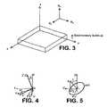
- FIG. 3is a schematic perspective view of a Cartesian coordinate system in a sedimentary earth formation
- FIG. 4shows a relationship between the coordinate systems of a borehole and a dipping formation bed
- FIG. 5shows a coordinate system for specifying the orientation of tilted loop antennas
- FIG. 6shows a block diagram of the circuitry used in accordance with the present invention.
- FIGS. 7A-7Nshow various illustrative antenna configurations for a resistivity logging tool
- FIG. 8shows an illustrative electromagnetic resistivity logging tool having compensated measurements
- FIG. 9is an illustrative graph of measured amplitude attenuation versus resistivity
- FIG. 10is an illustrative graph of measured phase shift versus resistivity
- FIG. 11shows an illustrative division of a borehore circumference into azimuthal bins
- FIG. 12shows an illustrative graph of measured phase resistivity as a function of rotation angle for different signal frequencies
- FIG. 13shows an illustrative graph of measured phase resistivity as a function of rotation angle for different transmitter-receiver spacings
- FIG. 14is an illustrative graph comparing phase and attenuation resistivities for different relative dip angles
- FIG. 15is an illustrative graph comparing phase resistivity as a function of dip angle for different transmitter-receiver spacings
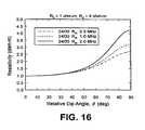
- FIG. 16is an illustrative graph comparing phase resistivity as a function of dip angle for different signal frequencies
- FIG. 17is a flow diagram of an illustrative resistivity logging method
- FIG. 18is an illustrative graph of the tool response at one azimuthal orientation
- FIG. 19is an illustrative graph of the tool response at an azimuthal orientation opposite that of FIG. 18 ;
- FIG. 20is an illustrative graph of the difference between the tool responses of FIGS. 18 and 19 .
- Some of the disclosed methods and systemsmeasure sinusoidal variation of azimuthally sensitive resistivity logging tool measurements, determine parameters representative of the sinusoidal variation, and perform inversion based on the sinusoidal parameters. When cast in this manner, the inversion process may yield more accurate and consistent resistivity and dip angle estimates.
- the sinusoidal parameterspreferably take the form of average and peak-to-peak measurements, but may also take other forms. Moreover, use of such sinusoidal parameters enables a condensed representation of the resistivity logging tool measurements, enabling significantly more efficient communication and storage of these measurements. The condensed representations continue to enable directional boundary detection and geosteering.
- FIG. 1An illustrative logging while drilling (LWD) environment is shown in FIG. 1 .
- a drilling platform 102supports a derrick 104 having a traveling block 106 for raising and lowering a drill string 108 .
- a kelly 110supports the drill string 8 as it is lowered through a rotary table 12 .
- a drill bit 14is driven by a downhole motor and/or rotation of the drill string 8 . As bit 14 rotates, it creates a borehole 16 that passes through various formations 18 .
- a pump 20circulates drilling fluid through a feed pipe 22 to kelly 10 , downhole through the interior of drill string 8 , through orifices in drill bit 14 , back to the surface via the annulus around drill string 8 , and into a retention pit 24 .
- the drilling fluidtransports cuttings from the borehole into the pit 24 and aids in maintaining the borehole integrity.
- FIG. 1An illustrative logging while drilling (LWD) environment is shown in FIG. 1 .
- a drilling platform 102is equipped with a derrick 104 that supports a hoist 106 for raising and lowering a drill string 108 .
- the hoist 106suspends a top drive 110 that is used to rotate the drill string 108 and to lower the drill string through the well head 112 .
- Connected to the lower end of the drill string 108is a drill bit 114 . As bit 114 rotates, it creates a borehole 120 that passes through various formations 118 .
- a pump 116circulates drilling fluid through a supply pipe 118 to top drive 110 , downhole through the interior of drill string 108 , through orifices in drill bit 114 , back to the surface via the annulus around drill string 108 , and into a retention pit 124 .
- the drilling fluidtransports cuttings from the borehole into the pit 124 and aids in maintaining the integrity of the borehole 120 .
- downhole sensorsincluding resistivity logging tool 126
- an acoustic telemetry transmitter 128that transmits telemetry signals in the form of acoustic vibrations in the tubing wall of drill string 108 .
- An acoustic telemetry receiver array 130may be coupled to tubing below the top drive 110 to receive transmitted telemetry signals.
- One or more repeater modules 132may be optionally provided along the drill string to receive and retransmit the telemetry signals.
- An electromagnetic resistivity logging tool 126is integrated into the bottom-hole assembly near the bit 114 . As the bit extends the borehole through the formations, logging tool 126 collects measurements relating to various formation properties as well as the tool orientation and position and various other drilling conditions.
- the logging tool 126may take the form of a drill collar, i.e., a thick-walled tubular that provides weight and rigidity to aid the drilling process.
- a telemetry sub 128may be included to transfer tool measurements to a surface receiver 130 and to receive commands from the surface receiver. In some alternative embodiments, the telemetry sub 128 collects and stores tool measurements for later retrieval when the tool is brought back to the surface.
- the orientation measurementsmay be performed using an azimuthal orientation indicator, which may include magnetometers, inclinometers, and/or accelerometers, though other sensor types such as gyroscopes may be used.
- the toolincludes a 3-axis fluxgate magnetometer and a 3-axis accelerometer.
- the combination of those two sensor systemsenables the measurement of the toolface angle, borehole inclination angle, and borehole azimuth angle.
- the toolface and hole inclination anglesare calculated from the accelerometer sensor output.
- the magnetometer sensor outputsare used to calculate the hole azimuth.
- the drill string 108is removed from the borehole as shown in FIG. 2 .
- logging operationscan be conducted using a wireline logging tool 134 , i.e., a sensing instrument sonde suspended by a cable 142 having conductors for transporting power to the tool and telemetry from the tool to the surface.
- a resistivity imaging portion of the logging tool 134may have centralizing arms 136 that center the tool within the borehole as the tool is pulled uphole.
- a logging facility 144collects measurements from the logging tool 134 , and includes computing facilities for processing and storing the measurements gathered by the logging tool.
- FIGS. 1 and 2show formations 118 that are not perpendicular to the borehole, a situation that may occur naturally or may occur due to directional drilling operations.
- FIG. 3shows a portion of a sedimentary formation bed, with the z-axis oriented perpendicular to the plane of the formation in the direction of the sedimentary accretion.
- the formation resistivity when measured along this axisis often different than formation resistivity measured in the x-y plane.
- the x-axisis chosen to be oriented in the direction of deepest descent, i.e., “downhill”.
- the relationship between the formation coordinate system and the borehole coordinate systemis shown in FIG. 4 .
- the z-axis of the borehole coordinate systemis aligned with the borehole's long axis, and the x-axis of the borehole coordinate system is directed to the north side (or alternatively, the high side) of the hole.
- the two coordinate systemsare related by two rotations. Beginning with the formation coordinate system (x,y,z), a first rotation of angle ⁇ is made about the z axis. The resulting coordinate system is denoted (x′,y′,z′).
- Angle ⁇is the relative strike angle, which indicates the direction of the formation dip relative to the borehole's coordinate system.
- a second rotation of angle ⁇is then made about the y′ axis. This aligns the formation coordinate system with the borehole coordinate system.
- Angle ⁇is the relative dip angle, which is the slope angle of the beds relative to the long axis of the borehole.
- the vertical resistivityis generally found to be the resistivity as measured perpendicular to the plane of the formation
- the horizontal resistivityis the resistivity as measured within the plane of the formation. Determination of each of these parameters (dip angle, strike angle, vertical resistivity, and horizontal resistivity) is desirable. Accordingly, disclosed herein is an improved downhole method and apparatus for simultaneously determining the horizontal resistivity, vertical resistivity, and relative dip angle for anisotropic earth formations.
- Some system embodimentsemploy an electromagnetic logging tool having an antenna configuration in which a transmitter antenna and a receiver antenna are oriented in non-parallel planes such that the vertical resistivity and the relative dip angle are decoupled.
- either the transmitter or the receiveris mounted in a conventional orientation in a first plane that is normal to the tool axis, and the other antenna is mounted in a second plane that is not parallel to the first plane.
- the disclosed embodimentsare suitable for LWD applications, and are also applicable to wireline and possibly other applications.
- this steering capabilityis achieved by providing transmitter and receiver antennas that are mounted in non-parallel planes and computing the azimuthal difference or the ratio of the phase-based or amplitude-based responses of the receiver antennas. With such an antenna arrangement, the azimuthal ratio or difference of the responses indicates whether the resistivity of an approaching bed is higher or lower than the resistivity of the present bed. With such information, the driller may steer the drilling apparatus in order to maintain the borehole in a desired geological bed.
- FIG. 5shows a coordinate system for specifying the orientation of a loop antenna.
- the tool coordinate system(x′′, y′′, z′′) has a z-axis oriented parallel to the long axis of the logging tool.
- the x-axisis directed to the “tool face scribe line” that is used to specify the tool orientation.
- the orientation of the loop antennais represented by a normal vector N that is perpendicular to the plane of the loop antenna windings.
- the tilt angle of the antennais the angle ⁇ between the z-axis and the normal vector N.
- the azimuthal orientation ⁇ of the loop antennais the angle ⁇ between the x-axis and the projection of the normal vector N in the x-y plane.
- FIG. 6shows an illustrative logging tool 10 having N coaxial transmitter antennas T 1 , T 2 , T 3 , . . . , T N spaced along the length of the logging tool.
- Illustrative logging tool 10also has two tilted receiver antennas R 1 and R 2 that are axially spaced apart from the transmitter antennas and from each other.
- the transmitter and receiver antennasare mounted in recesses in tool 10 and are protected by a non-conductive material or a material with non-conducting apertures.
- each receiver antennaincludes a pair of coils, with one coil tuned to f 1 and one coil tuned to f 2 .
- the coils in each pairmay be located side by side around the periphery of tool 10 or may be concentrically stacked.
- the transmitter and receiver antennasmay be fabricated in accordance with the teachings of U.S. Pat. No. 4,940,943. It should be appreciated that the body of tool 10 is preferably made of steel in order to prevent tool 10 from becoming a weak link in the drill string 14 .
- logging tool 10also has the requisite electronic circuitry for processing the signals received by the receivers antennas as disclosed further below, thereby converting the received signals into a log or another indication of formation resistivity. It should also be appreciated that the processed signals can be recorded within the electronics section of tool 10 or may be coneyed to the surface by a telemetry system for concurrent processing and readout at the surface.
- the distance between the coils used for R 1 and R 2is preferably six inches along the longitudinal axis of tool 10 , but other receiver spacings may also be used.
- the distance between the receiver pair and the successively spaced transmitterswill vary in some applications, as discussed hereinafter in greater detail.
- a preferred configurationcontains a distance between T 1 and R 1 /R 2 of 12 inches/18 inches; a distance between T 2 and R 1 /R 2 of 24 inches/30 inches; and a distance between T 3 and R 1 /R 2 of 36 inches/42 inches.
- amplifiers A 1 , A 2 , A 3 . . . A Nare coupled to the transmitter coils T 1 , T 2 , T 3 . . . T N , respectively.
- Each of the amplifiersis in turn driven by an oscillators F 1 , F 2 , F 3 . . . F N .
- the operating frequencies of the oscillatorsare preferably between about 0.5 MHz up to about 4 MHz. Because of power attenuation at greater depths of investigation, such as is the case with the longer spaced transmitters, the frequencies preferably conform to the relationship F 1 ⁇ F 2 ⁇ F 3 ⁇ . . . F N .
- the oscillators F 1 , F 2 , F 3 . . . F Nare controlled by a transmitter enable circuit 30 , which interfaces with a microprocessor 32 , which in turn interfaces with a communication interface circuit 34 and an analog-to-digital (A/D) converter 36 .
- Communication interface circuit 34enables communication between the microprocessor 32 and a tool controller, integrated memory, a telemetry unit, and/or an external port for communicating with operators or computers once the tool has been removed from the borehole.
- the receiver antennas R 1 and R 2are respectively connected to amplifiers 40 and 42 , which are connected, respectively, to mixer circuits 44 and 46 .
- Oscillators F 1 , F 2 , F 3 . . . F Nare coupled to an oscillator select circuit 48 , the output of which is connected to the inputs of mixer circuits 44 and 46 .
- Oscillator select circuit 48interfaces to microprocessor 32 to determine which oscillater is to be coupled to the mixer circuits.
- the respective outputs of mixer circuits 44 and 46drive low pass filters 50 and 52 , respectively, the outputs of which drive amplitude measurement circuits 54 and 56 , respectively.
- the outputs of amplitude measurement circuits 54 and 56are connected to a multiplexer circuit 60 .
- the outputs of low pass filter circuits 50 and 52are also connected to the inputs of a relative phase measurement circuit 62 , the output of which is fed into multiplexer 60 .
- multiplexer 60forwards a selected one of its inputs to A/D converter 36 for sampling and conversion into a digital value that the microprocessor can store and process.
- the microprocessor 32further acquires tool orientation measurements from orientation sensors 70 , and determines a tool orientation to be associated with each resistivity measurement derived from the sampled receiver signals.
- the oscillators F 1 ′, F 2 ′, F 3 ′ . . . F N ′are designed to provide frequencies very near the corresponding frequencies F 1 , F 2 , F 3 . . . F N .
- F Ncan be set at a frequency of 1.998 MHz and thus provide an intermediate frequency coming out of mixer circuits 44 and 46 of 0.002 MHz (2 KHz).
- F 2 ′ and F 3 ′can be set at 1.998 MHz and 0.998 MHz, respectively.
- the only signals that pass to low pass filters 50 and 52will be the intermediate frequencies which are obtained by mixing the frequencies of F 1 , F 2 , F 3 . . . F N with the frequencies F 1 ′, F 2 ′, F 3 ′ . . . F N ′, respectively.
- amplitude measurement circuit 54provides a measure of the amplitude of the signal received by receiver antenna R 1
- amplitude measurement circuit 56measures the amplitude of the incoming signals received by receiver antenna R 2
- relative phase measurement circuit 62provides an indication of the phase difference between the signals received at receiver antenna R 1 and the signals received at receiver antenna R 2 .
- the amplitude measurements (A) and the phase measurements ( ⁇ )are each indicative of formation resistivity.
- the frequencies F 1 , F 2 , F 3 . . . F Ncould all be the same frequency, though some embodiments employ different frequencies to account for increased power loss in the formation for larger transmitter-receiver antenna spacings.
- the individual transmitter antennasfire in sequence, though in some alternative embodiments, simultaneous operation of the transmitter antennas is possible.
- simultaneous transmission of all of the transmitter signalswill usually require additional filters and processing circuitry to enable the instrument to properly discriminate between the different frequencies.
- FIGS. 7A-7Nillustrate a variety of contemplated transmitter/receiver antenna configurations, each having azimuthal sensitivity due to a tilted transmitter antenna, a tilted receiver antenna, or both.
- FIG. 7Ashows tool having a coaxial transmitter antenna T 1 and a tilted receiver antenna R 1 .
- FIG. 7Bshows a tool having a tilted transmitter antenna T 1 and a coaxial receiver antenna R 1 .
- the antenna configurationdoes not necessarily include a coaxial antenna.
- FIG. 7Cshows a tool having a transmitter antenna T 1 tilted at an angle ⁇ T1 and a receiver antenna R 1 tilted at an angle ⁇ R1 .
- FIGS. 7A-7Cprovide useful resistivity measurements, such measurements generally suffer from asymmetric responses at bed boundaries, often making the resistivity logs unnecessarily difficult to interpret.
- FIG. 7Dshows a tool having a tilted receiver antenna R 1 positioned midway between two coaxial transmitter antennas T 1 , T 2 .
- FIG. 7Eshows a tool having a coaxial receiver antenna R 1 positioned midway between two tilted transmitter antennas T 1 , T 2 .
- the titlted transmitter antennas of FIG. 7Eare parallel, but this is optional, as shown by the transmitter antennas in FIG. 7F , which are tilted at opposite azimuthal angles.
- FIG. 7Gshows a tool having a first transmitter antenna T 1 tilted at an angle ⁇ T1 , a second transmitter antenna T 2 tilted at an angle ⁇ T2 , and a receiver antenna R 1 tilted at an angle ⁇ R1 .
- FIGS. 7A-7Gare suitable for making absolute (non-differential) attenuation and phase shift measurements. While such measurements are useful, they may not have sufficient spatial resolution.
- differential antenna configurationsmay be employed.
- FIG. 7Hshows a tool having a coaxial transmitter antenna T 1 and a pair of tilted receiver antennas R 1 and R 2 .
- FIG. 7Ishows a tool having a tilted transmitter antenna T 1 and a pair of coaxial receiver antennas R 1 and R 2 .
- This antenna configurationdoes not necessarily include a coaxial antenna, and the pair of receiver antennas are not necessarily parallel.
- 7Jshows a tool having a transmitter antenna T 1 tilted at an angle ⁇ T1 , a first receiver antenna R 1 tilted at an angle ⁇ R1 , and a second receiver antenna R 2 tilted at an angle ⁇ R2 .
- FIG. 7Kshows an antenna configuration having a pair of co-located receiver antennas R 1 and R 2 that are tilted in different azimuthal directions.
- This antenna configurationmay be particularly suitable for deriving a directional steering signal.
- FIG. 7Lshows a tool having a pair of tilted receiver antennas R 1 and R 2 having a midpoint centered between two coaxial transmitter antennas T 1 and T 2 .
- FIG. 7Mshows a tool having a pair of coaxial receiver antennas R 1 and R 2 having a midpoint centered between two tilted transmitter antennas T 1 and T 2 .
- the tilted antennasmay be parallel, but are not necessarily so.
- the transmitter and receiver rolesmay be exchanged in accordance with the principle of reciprocity.
- FIG. 7Nshows a pair of coaxial transmitter antennas T 1 and T 2 having a midpoint centered between two tilted receiver antennas R 1 and R 2 . Furthermore, in each of the foregoing antenna configurations, additional transmitter and receiver antennas may be present to enable measurements at additional transmitter-receiver antenna spacings.
- FIG. 8illustrates the amplitude and phase measurements that may be made by a compensated resistivity logging tool 802 .
- receiver antennas 810 and 812measure signals having an attenuation A 1 and A 2 , respectively, and having phase shifts ⁇ 1 and ⁇ 2 , respectively. From these measurements a first differential attenuation (logA 2 -logA 1 ) and differential phase ( ⁇ 2 - ⁇ 1 ) can be determined.
- receiver antennas 810 and 812measure signals having an attenuation A 4 and A 3 , respectively, and having phase shifts ⁇ 4 and ⁇ 3 , respectively.
- a second differential attenuation (logA 4 -logA 3 ) and second differential phase ( ⁇ 4 - ⁇ 3 )can be determined.
- the first and second differential attenuation measurementscan then be averaged together (as can the first and second differential phase measurements) to obtain a compensated measurement, i.e., a measurement in which fixed biases in the electronics are canceled.
- the disclosed logging tools and methodsemploy one or more tilted antennas to obtain azimuthally-sensitive resistivity measurements.
- the circumference of the tool (or borehole)is divided into azimuthal bins as shown in FIG. 11 , and as the tool rotates and the tool face scribe line passes through each azimuthal bin, a set of resistivity measurements is made within each bin at a given position in the borehole.
- the number of binsranges as low as 6 or 8 bins, and as high as 16 or 32 bins.
- multiple measurement setsmay be obtained within each bin and combined (e.g., by averaging).
- FIG. 12illustrates the azimuthal dependence of phase resistivity measurements at different frequencies in a dipping anisotropic formation.
- FIG. 13illustrates the azimuthal dependence of phase resistivity measurements at different transmitter-receiver spacings.
- the resistivity measurementsare approximately sinusoidal. The sinusoidal-like nature of these measurements is preferably exploited to condense the azimuthally-dependent measurements into a representative set of characteristic parameters.
- the characteristic parametersare (1) a mean value, (2) a max-to-min difference value, and (3) an identifier for the location of the peak of the sinusoid (e.g., an azimuthal bin number). Other sets of representative characteristic parameters may also be employed.
- a tthe cross-sectional area of the transmitter coil
- ⁇the relative dip angle (the angle between the tool axis and the normal to the formation).
- the HMDproduces magnetic fields H hx and H hz
- the VMDproduces magnetic fields H vx and H vz as follows:
- H hxM T ⁇ sin ⁇ ⁇ ⁇ 4 ⁇ ⁇ ⁇ ( e i ⁇ ⁇ k h ⁇ L L 3 ⁇ [ 3 ⁇ sin 2 ⁇ ⁇ - 1 + k n 2 ⁇ L 2 ⁇ cos 2 ⁇ ⁇ + i ⁇ ⁇ k h ⁇ L sin 2 ⁇ ⁇ + i ⁇ ⁇ k h ⁇ L ⁇ - 3 ⁇ i ⁇ ⁇ k h ⁇ L ⁇ ⁇ sin 2 ⁇ ⁇ ] - i ⁇ ⁇ k h sin 2 ⁇ ⁇ ⁇ e i ⁇ ⁇ k h ⁇ L ⁇ ⁇ ⁇ ) ⁇ e i ⁇ ⁇ k h ⁇ L [ 3 ]
- H hzM T ⁇ cos ⁇ ⁇ ⁇ 4 ⁇ ⁇ ⁇ ( e i ⁇ ⁇ k h ⁇ L L 3 ⁇ [ 3 ⁇ co
- Vi ⁇ ⁇ ⁇ A r ⁇ ⁇ ⁇ ⁇ I t ⁇ A t 4 ⁇ ⁇ ⁇ ⁇ L 3 ⁇ ( [ 2 - i ⁇ ⁇ k h ⁇ L ] ⁇ e i ⁇ ⁇ k h ⁇ L - i ⁇ ⁇ k h ⁇ L ⁇ ⁇ e i ⁇ ⁇ k h ⁇ L ⁇ ⁇ ⁇ ) [ 9 ]
- Equation [9]shows that the induced voltage, V, depends on k h and ⁇ .
- k hdepends on ⁇ h ; and ⁇ depends on ⁇ h , ⁇ v , and ⁇ .
- ⁇ v and ⁇are dependent, and this dependency prevents convergence of a simultaneous solution for ⁇ h , ⁇ v , and ⁇ .
- the above formulationis for an coaxial transmitter with a tilted receiver, the theory of reciprocity provides that the same result also applies to a tilted transmitter with an untilted receiver. Indeed, both the transmitter and the receiver may be tilted, provided that the respective angles of tilt are not the same, i.e., ⁇ T ⁇ R .
- FIGS. 14-16illustrate the dip dependence of the sinusoid peak values for a typical earth formation having a horizontal resistivity of 1 ohm-m and a vertical resistivity of 4 ohm-m.
- FIG. 14depicts amplitude attenuation resistivity and phase shift resistivity as a function of relative dip angle using a single transmitter-receiver pair at a single frequency.
- FIG. 15depicts phase shift resistivity as a function of relative dip angle using three transmitter-receiver pair spacings at a single frequency.
- FIG. 16depicts phase shift resistivity as a function of relative dip angle using a single transmitter-receiver pair at three different frequencies.
- FIG. 17shows an illustrative resistivity logging process to determine horizontal resistivity, vertical resistivity, and relative dip angle as a function of position along the borehole.
- the logging tooldrives the selected transmit antenna at the selected frequency, and measures the receiver responses.
- the logging toolfurther measures the tool position and orientation to be associated with the measured receiver responses.
- the receiver responsesmay be absolute phase shift, absolute attenuation, differential phase shift, and/or differential attenuation.
- the position and orientation informationis used to associate the measured receiver responses with an azimuthal bin. If multiple measurements are obtained for a given bin, the measurements may be combined, e.g., by averaging.
- a testis made to determine if there are more measurements to be made at this position in the borehole (e.g., a test to see if the measured tool position is still within a predetermined range). If so, blocks 1702 - 1708 are repeated.
- the characteristic parametersare inverted to determine one or more of the formation strike angle, the formation dip angle, the formation resistivity (horizontal or vertical), and the formation anisotropy.
- the determined formation measurementsare stored in the form of a log, which may be optionally displayed and updated in block 1716 .
- a testis made to determine whether the logging should continue (e.g., whether the drilling process is ongoing), and if so, blocks 1702 - 1718 are repeated.
- the inversion processcan take the form of a look-up table-based search with interpolation, but is preferably performed with a closed-form forward model of the tool responses that are expected in response to estimates of the formation dip, resistivity, and anisotropy. Beginning with random, arbitrary, or in some cases, predetermined, estimates of the formation dip, resistivity, and anisotropy, the inversion process repeatedly updates these estimates until the sinusoidal parameter values predicted by the forward model match the measured sinusoidal parameter values to within some predetermined threshold.
- the update routinemay, for example, employ the Levenberg-Marquardt method discussed by Tianfei Zhu and Larry D. Brown, “Two-dimensional Velocity Inversion and Synthetic Seismogram Computation,” Geophysics, vol. 52, no. 1, January 1987, p. 37-50.
- the measured characteristic parameter valuesare the mean and the max-to-min difference values of the differential phase shift measured as a function of azimuth at each of three or more transmit frequencies.
- the characteristic parameter valuesare the mean and max-to-min difference values of the differential attenuation measured as a function of azimuth at three or more transmitter-to-receiver spacings.
- both phase and attenuation informationare measured and used as the basis of the inversion. Other characteristic parameter values are possible and may be used.
- the tool response to a boundary between isotropic formationsexhibits a sinusoidal response much like those shown in FIGS. 12 and 13 .
- the maximum value of the responseoccurs in the azimuthal direction towards nearby boundaries with regions of higher conductivity and in the azimuthal direction away from nearby boundaries with regions of lower conductivity.
- the minimum value of the responseoccurs in the azimuthal direction away from boundaries with regions of higher conductivity and in the azimuthal direction toward nearby boundaries with regions of lower conductivity.
- the direction of the steering signalis consistent as the tool crosses a boundary.
- the max-to-min difference and the peak orientation indicatorcan be used as the steering signal.
- a max-to-mean difference and peak orientation indicatorcould be employed to similar effect.
- a ratio of max-to-min valueis employed.
- the drilling operatormay combine the steering signal information with tool position and orientation measurements and knowledge derived from test holes or seismic surveys to formulate directional steering decisions.
- the steering signals described hereinare expected to be particularly effective at enabling a drilling operator to effectively detect and enter a payzone and at enabling the drilling operator to maintain a borehole course that maximizes the borehole interval in the payzone.
Landscapes
- Physics & Mathematics (AREA)
- Life Sciences & Earth Sciences (AREA)
- Engineering & Computer Science (AREA)
- Remote Sensing (AREA)
- Electromagnetism (AREA)
- Environmental & Geological Engineering (AREA)
- Geology (AREA)
- General Life Sciences & Earth Sciences (AREA)
- General Physics & Mathematics (AREA)
- Geophysics (AREA)
- Geophysics And Detection Of Objects (AREA)
- Measurement Of Resistance Or Impedance (AREA)
Abstract
Description
MT
MT
where
- kh=the complex wave number in the horizontal direction
- kv=the complex wave number in the vertical direction
- ω=the angular frequency (in radians/second) of the transmitter coil=2πf
- f=the frequency of the transmitter coil (in Hertz)
- μ=the magnetic permeability of the formation (assume μ=μair)
- σh=the horizontal conductivity of the formation
- σv=the vertical conductivity of the formation
- εh=the horizontal dielectric constant (assumed)
- εv=the vertical dielectric constant (assumed)
- L=the distance between the transmitter coil and the receiver coil, and
- i=√{square root over (−1)}
Hz=(Hhx+Hvx)sin θ+(Hvz+Hhz)cos θ [7a]
and the Hxfield (the field perpendicular to the z-axis of the tool and in the x-z plane of the formation coordinate system) is given by the equation
Hx=(Hhx+Hvx)cos θ−(Hvz+Hhz)sin θ. [7b]
V=iωArμ(Hzcos ξR+Hxsin ξRcos α+Hysin ξRsin α) [8]
where Aris the cross-sectional area of the receiver coil. From the foregoing equations, it can be shown that when the transmitter and receiver antennas are parallel, the induced receiver voltage is
Claims (20)
Applications Claiming Priority (1)
| Application Number | Priority Date | Filing Date | Title |
|---|---|---|---|
| PCT/US2007/064221WO2008115229A1 (en) | 2007-03-16 | 2007-03-16 | Robust inversion systems and methods for azimuthally sensitive resistivity logging tools |
Publications (2)
| Publication Number | Publication Date |
|---|---|
| US20100156424A1 US20100156424A1 (en) | 2010-06-24 |
| US8085050B2true US8085050B2 (en) | 2011-12-27 |
Family
ID=39766192
Family Applications (1)
| Application Number | Title | Priority Date | Filing Date |
|---|---|---|---|
| US12/299,760ActiveUS8085050B2 (en) | 2007-03-16 | 2007-03-16 | Robust inversion systems and methods for azimuthally sensitive resistivity logging tools |
Country Status (6)
| Country | Link |
|---|---|
| US (1) | US8085050B2 (en) |
| AU (1) | AU2007349251B2 (en) |
| BR (1) | BRPI0711465B1 (en) |
| GB (1) | GB2459067B (en) |
| NO (2) | NO343049B1 (en) |
| WO (1) | WO2008115229A1 (en) |
Cited By (36)
| Publication number | Priority date | Publication date | Assignee | Title |
|---|---|---|---|---|
| US20100117655A1 (en)* | 1999-01-28 | 2010-05-13 | Halliburton Energy Services, Inc. | Tool for Azimuthal Resistivity Measurement and Bed Boundary Detection |
| US20110175899A1 (en)* | 2007-03-27 | 2011-07-21 | Halliburton Energy Services, Inc. | Systems and methods for displaying logging data |
| US20110291855A1 (en)* | 2008-10-01 | 2011-12-01 | Homan Dean M | Logging tool with antennas having equal tilt angles |
| US20110309833A1 (en)* | 2010-06-22 | 2011-12-22 | Jian Yang | Determining resistivity anistotropy and formation structure for vertical wellbore sections |
| US20120105076A1 (en)* | 2010-11-02 | 2012-05-03 | Smith International, Inc. | Method of correcting resistivity measurements for toll bending effects |
| US8222902B2 (en) | 2006-07-11 | 2012-07-17 | Halliburton Energy Services, Inc. | Modular geosteering tool assembly |
| US8274289B2 (en) | 2006-12-15 | 2012-09-25 | Halliburton Energy Services, Inc. | Antenna coupling component measurement tool having rotating antenna configuration |
| US20130226461A1 (en)* | 2011-04-18 | 2013-08-29 | Halliburton Energy Services, Inc. | Method for real-time downhole processing and detection of bed boundary for geosteering application |
| US20130239673A1 (en)* | 2010-06-24 | 2013-09-19 | Schlumberger Technology Corporation | Systems and Methods for Collecting One or More Measurements in a Borehole |
| US8593147B2 (en) | 2006-08-08 | 2013-11-26 | Halliburton Energy Services, Inc. | Resistivity logging with reduced dip artifacts |
| US20140132420A1 (en)* | 2012-11-09 | 2014-05-15 | Greatwall Drilling Company | Apparatus and Method for Multi-Mode and Multi-Depth Resistivity Measurements |
| US8749243B2 (en) | 2010-06-22 | 2014-06-10 | Halliburton Energy Services, Inc. | Real time determination of casing location and distance with tilted antenna measurement |
| US20140257704A1 (en)* | 2013-03-05 | 2014-09-11 | Ce Liu | Apparatus and Method for Bed Boundary Detection |
| US8917094B2 (en) | 2010-06-22 | 2014-12-23 | Halliburton Energy Services, Inc. | Method and apparatus for detecting deep conductive pipe |
| US20150011159A1 (en)* | 2013-07-05 | 2015-01-08 | Gilat Satellite Networks Ltd. | System for dual frequency range mobile two-way satellite communications |
| US9002649B2 (en) | 2010-07-16 | 2015-04-07 | Halliburton Energy Services, Inc. | Efficient inversion systems and methods for directionally-sensitive resistivity logging tools |
| US9110188B2 (en) | 2013-07-12 | 2015-08-18 | Halliburton Energy Services, Inc. | Detecting bed boundary locations based on gradients determined from measurements from multiple tool depths in a wellbore |
| US9115569B2 (en) | 2010-06-22 | 2015-08-25 | Halliburton Energy Services, Inc. | Real-time casing detection using tilted and crossed antenna measurement |
| US20160041233A1 (en)* | 2014-08-08 | 2016-02-11 | Halliburton Energy Services, Inc. | Low-noise fluxgate magnetometer with increased operating temperature range |
| US9268053B2 (en) | 2013-06-12 | 2016-02-23 | Well Resolutions Technology | Apparatus and methods for making azimuthal resistivity measurements |
| US9310508B2 (en) | 2010-06-29 | 2016-04-12 | Halliburton Energy Services, Inc. | Method and apparatus for sensing elongated subterranean anomalies |
| US9364905B2 (en) | 2010-03-31 | 2016-06-14 | Halliburton Energy Services, Inc. | Multi-step borehole correction scheme for multi-component induction tools |
| US9411068B2 (en) | 2008-11-24 | 2016-08-09 | Halliburton Energy Services, Inc. | 3D borehole imager |
| US9575202B2 (en)* | 2013-08-23 | 2017-02-21 | Baker Hughes Incorporated | Methods and devices for extra-deep azimuthal resistivity measurements |
| US9678240B2 (en) | 2013-07-18 | 2017-06-13 | Halliburton Energy Services, Inc. | Detecting boundary locations of multiple subsurface layers |
| US9732559B2 (en) | 2008-01-18 | 2017-08-15 | Halliburton Energy Services, Inc. | EM-guided drilling relative to an existing borehole |
| US9752428B2 (en) | 2012-12-18 | 2017-09-05 | Halliburton Energy Services, Inc. | Methods and apparatus to acquire compensated signals for determination of formation parameters |
| US9909414B2 (en) | 2009-08-20 | 2018-03-06 | Halliburton Energy Services, Inc. | Fracture characterization using directional electromagnetic resistivity measurements |
| US10087744B2 (en) | 2013-01-17 | 2018-10-02 | Halliburton Energy Services, Inc. | Fast formation dip angle estimation systems and methods |
| US20180371900A1 (en)* | 2011-03-07 | 2018-12-27 | Halliburton Energy Services, Inc. | Signal Processing Methods for Steering to an Underground Target |
| US10317563B2 (en) | 2015-10-26 | 2019-06-11 | Halliburton Energy Services, Inc. | Frequency ratiometric processing of resistivity logging tool data |
| US10330818B2 (en) | 2011-10-31 | 2019-06-25 | Halliburton Energy Services, Inc. | Multi-component induction logging systems and methods using real-time OBM borehole correction |
| US10358911B2 (en) | 2012-06-25 | 2019-07-23 | Halliburton Energy Services, Inc. | Tilted antenna logging systems and methods yielding robust measurement signals |
| US20200270980A1 (en)* | 2017-12-14 | 2020-08-27 | Halliburton Energy Services, Inc. | Azimuth Estimation For Directional Drilling |
| US11307322B2 (en)* | 2016-09-19 | 2022-04-19 | Halliburton Energy Services, Inc. | Mixed inversion using a coarse layer model |
| US11454102B2 (en) | 2016-05-11 | 2022-09-27 | Baker Hughes, LLC | Methods and systems for optimizing a drilling operation based on multiple formation measurements |
Families Citing this family (35)
| Publication number | Priority date | Publication date | Assignee | Title |
|---|---|---|---|---|
| US6163155A (en) | 1999-01-28 | 2000-12-19 | Dresser Industries, Inc. | Electromagnetic wave resistivity tool having a tilted antenna for determining the horizontal and vertical resistivities and relative dip angle in anisotropic earth formations |
| EP1956395A1 (en)* | 2007-02-06 | 2008-08-13 | Services Pétroliers Schlumberger | An antenna of an electromagnetic probe for investigating geological formations |
| WO2008115229A1 (en) | 2007-03-16 | 2008-09-25 | Halliburton Energy Services, Inc. | Robust inversion systems and methods for azimuthally sensitive resistivity logging tools |
| US8207738B2 (en)* | 2009-03-24 | 2012-06-26 | Smith International Inc. | Non-planar antennae for directional resistivity logging |
| US20100305862A1 (en)* | 2009-06-02 | 2010-12-02 | Smith International, Inc. | Borehole compensated resistivity logging tool having an asymmetric antenna spacing |
| US8547103B2 (en)* | 2010-03-15 | 2013-10-01 | Baker Hughes Incorporated | Multiple depths of investigation using two transmitters |
| US8669765B2 (en)* | 2010-03-15 | 2014-03-11 | Baker Hughes Incorporated | Estimating a parameter of interest with transverse receiver toroid |
| CN102870014B (en)* | 2010-04-15 | 2017-01-18 | 哈里伯顿能源服务公司 | Processing and geosteering with rotating tool |
| AU2011361786B2 (en)* | 2011-03-07 | 2014-12-18 | Halliburton Energy Services, Inc. | Signal processing methods for steering to an underground target |
| US9239403B2 (en)* | 2011-08-29 | 2016-01-19 | Hallibburton Energy Services, Inc. | Apparatus and methods of controlling recordation of resistivity-related readings in determining formation resistivity |
| WO2013048375A1 (en) | 2011-09-27 | 2013-04-04 | Halliburton Energy Services, Inc. | Systems and methods of robust determination of boundaries |
| BR112014011728A2 (en) | 2011-11-15 | 2017-05-09 | Halliburton Energy Services Inc | method and apparatus of operation, and machine readable storage device |
| WO2013074411A2 (en)* | 2011-11-15 | 2013-05-23 | Halliburton Energy Services, Inc. | Enhanced resistivity measurement apparatus, methods, and systems |
| MX348211B (en) | 2012-06-29 | 2017-06-05 | Halliburton Energy Services Inc | Multi - axial induction borehole imager. |
| CA2876326A1 (en)* | 2012-06-29 | 2014-01-03 | Halliburton Energy Services, Inc. | Full tensor micro-impedance imaging |
| BR112015000699A2 (en)* | 2012-07-13 | 2017-06-27 | Halliburton Energy Services Inc | resistivity profile estimation method of anisotropic formation using a multi-component induction tool |
| CA2895018C (en)* | 2012-12-31 | 2019-02-12 | Halliburton Energy Services, Inc. | Deep azimuthal system with multi-pole sensors |
| BR112015012050A2 (en) | 2012-12-31 | 2019-12-17 | Halliburton Energy Services Inc | formation imaging with multipole antennas |
| US20140253131A1 (en)* | 2013-03-05 | 2014-09-11 | Ce Liu | Apparatus and Method for Directional Resistivity Measurement While Drilling Using Slot Antenna |
| WO2014142982A1 (en) | 2013-03-15 | 2014-09-18 | Halliburton Energy Services, Inc. | Identifying unconventional formations |
| WO2015084390A1 (en) | 2013-12-06 | 2015-06-11 | Halliburton Energy Services, Inc. | Fracture detection and characterization using resistivity images |
| US10365395B2 (en) | 2014-03-11 | 2019-07-30 | Halliburton Energy Services, Inc. | Multi-component induction logging systems and methods using blended-model inversion |
| US10295698B2 (en) | 2014-04-03 | 2019-05-21 | Halliburton Energy Services, Inc. | Multi-component induction logging systems and methods using selected frequency inversion |
| WO2016099504A1 (en)* | 2014-12-18 | 2016-06-23 | Halliburton Energy Services, Inc. | Shoulder effect reduction |
| GB2545372B (en)* | 2014-12-31 | 2020-10-21 | Halliburton Energy Services Inc | Improving geosteering inversion using look-ahead look-around electromagnetic tool |
| CN107002488A (en) | 2014-12-31 | 2017-08-01 | 哈利伯顿能源服务公司 | Formation logging using multicomponent signal-based measurements of anisotropic permittivity and resistivity |
| US10190411B2 (en)* | 2015-11-12 | 2019-01-29 | Halliburton Energy Services, Inc. | Downhole fluid characterization methods and systems using multi-electrode configurations |
| US10261209B2 (en)* | 2016-02-29 | 2019-04-16 | China Petroleum & Chemical Corporation | Near-bit ultradeep measurement system for geosteering and formation evaluation |
| US10317565B2 (en)* | 2016-03-10 | 2019-06-11 | Halliburton Energy Services, Inc. | Induction logging borehole correction for water-based mud |
| US11035981B2 (en) | 2018-11-16 | 2021-06-15 | Halliburton Energy Services, Inc. | Air-hang calibration for resistivity-logging tool |
| CN110005398B (en)* | 2019-04-04 | 2024-03-22 | 中国石油大学(北京) | Method and device for determining design parameters of electromagnetic wave resistivity logging instrument while drilling |
| GB2639419A (en)* | 2022-10-25 | 2025-09-24 | China Petroleum & Chem Corp | Data compression determination and processing method for resistivity logging, and system |
| US12326078B2 (en) | 2023-07-19 | 2025-06-10 | Halliburton Energy Services, Inc. | Effective resistivity models for geosteering decisions |
| CN117328862B (en)* | 2023-12-01 | 2024-02-13 | 齐鲁工业大学(山东省科学院) | Holographic logging method and transmitting and receiving circuit applied to azimuth logging while drilling tool |
| CN120447076B (en)* | 2025-07-11 | 2025-09-12 | 中国石油大学(华东) | Rapid calculation method for electromagnetic wave logging response while drilling by far detection of complex stratum structure |
Citations (146)
| Publication number | Priority date | Publication date | Assignee | Title |
|---|---|---|---|---|
| US2901689A (en) | 1957-01-23 | 1959-08-25 | Engineering Res Corp | Method of exploring the earth with electromagnetic energy |
| US3014177A (en) | 1957-06-24 | 1961-12-19 | Shell Oil Co | Electromagnetic earth surveying apparatus |
| US3187252A (en) | 1961-12-18 | 1965-06-01 | Shell Oil Co | Electromagnetic well surveying method and apparatus for obtaining both a dip and conductivity anisotropy of a formation |
| US3286163A (en) | 1963-01-23 | 1966-11-15 | Chevron Res | Method for mapping a salt dome at depth by measuring the travel time of electromagnetic energy emitted from a borehole drilled within the salt dome |
| US3412815A (en) | 1966-11-14 | 1968-11-26 | Chevron Res | Electromagnetic radiation method for guiding the drilling of oil wells after the borehole has entered a massive earth formation of chemically deposited material, by a mistake, accident, or the like |
| US3510757A (en) | 1966-09-01 | 1970-05-05 | Schlumberger Technology Corp | Formation dip measuring methods and apparatus using induction coils |
| US3539911A (en) | 1968-06-21 | 1970-11-10 | Dresser Ind | Induction well logging apparatus having investigative field of asymmetric sensitivity |
| US3561007A (en) | 1967-09-12 | 1971-02-02 | Schlumberger Technology Corp | Methods and apparatus for investigating earth formations utilizing rotating electromagnetic fields |
| US3808520A (en) | 1973-01-08 | 1974-04-30 | Chevron Res | Triple coil induction logging method for determining dip, anisotropy and true resistivity |
| US3982176A (en) | 1974-12-11 | 1976-09-21 | Texaco Inc. | Combination radio frequency dielectric and conventional induction logging system |
| US4302722A (en) | 1979-06-15 | 1981-11-24 | Schlumberger Technology Corporation | Induction logging utilizing resistive and reactive induced signal components to determine conductivity and coefficient of anisotropy |
| US4319191A (en) | 1980-01-10 | 1982-03-09 | Texaco Inc. | Dielectric well logging with radially oriented coils |
| US4360777A (en) | 1979-12-31 | 1982-11-23 | Schlumberger Technology Corporation | Induction dipmeter apparatus and method |
| US4536714A (en) | 1982-04-16 | 1985-08-20 | Schlumberger Technology Corporation | Shields for antennas of borehole logging devices |
| EP0093519B1 (en) | 1982-04-29 | 1985-08-28 | Mobil Oil Corporation | Method of preparing high silica zeolites with control of zeolite morphology |
| US4553097A (en) | 1982-09-30 | 1985-11-12 | Schlumberger Technology Corporation | Well logging apparatus and method using transverse magnetic mode |
| US4611173A (en) | 1983-01-11 | 1986-09-09 | Halliburton Company | Induction logging system featuring variable frequency corrections for propagated geometrical factors |
| US4610313A (en) | 1984-02-15 | 1986-09-09 | Reed Tool Company | Drill bit having a failure indicator |
| US4636731A (en) | 1984-12-31 | 1987-01-13 | Texaco Inc. | Propagation anisotropic well logging system and method |
| US4651101A (en) | 1984-02-27 | 1987-03-17 | Schlumberger Technology Corporation | Induction logging sonde with metallic support |
| US4697190A (en) | 1984-11-02 | 1987-09-29 | Coal Industry (Patents) Limited | Borehole located directional antennae means for electromagnetic sensing systems |
| US4700142A (en) | 1986-04-04 | 1987-10-13 | Vector Magnetics, Inc. | Method for determining the location of a deep-well casing by magnetic field sensing |
| US4780857A (en) | 1987-12-02 | 1988-10-25 | Mobil Oil Corporation | Method for logging the characteristics of materials forming the walls of a borehole |
| US4785247A (en) | 1983-06-27 | 1988-11-15 | Nl Industries, Inc. | Drill stem logging with electromagnetic waves and electrostatically-shielded and inductively-coupled transmitter and receiver elements |
| US4791373A (en) | 1986-10-08 | 1988-12-13 | Kuckes Arthur F | Subterranean target location by measurement of time-varying magnetic field vector in borehole |
| US4808929A (en) | 1983-11-14 | 1989-02-28 | Schlumberger Technology Corporation | Shielded induction sensor for well logging |
| USRE32913E (en) | 1982-04-16 | 1989-04-25 | Schlumberger Technology Corp. | Shields for antennas of borehole logging devices |
| US4845433A (en) | 1984-05-31 | 1989-07-04 | Schlumberger Technology Corporation | Apparatus for microinductive investigation of earth formations |
| US4873488A (en) | 1985-04-03 | 1989-10-10 | Schlumberger Technology Corporation | Induction logging sonde with metallic support having a coaxial insulating sleeve member |
| US4899112A (en) | 1987-10-30 | 1990-02-06 | Schlumberger Technology Corporation | Well logging apparatus and method for determining formation resistivity at a shallow and a deep depth |
| US4933640A (en) | 1988-12-30 | 1990-06-12 | Vector Magnetics | Apparatus for locating an elongated conductive body by electromagnetic measurement while drilling |
| US4940943A (en) | 1988-04-19 | 1990-07-10 | Baroid Technology, Inc. | Method and apparatus for optimizing the reception pattern of the antenna of a propagating electromagnetic wave logging tool |
| US4945987A (en) | 1986-12-31 | 1990-08-07 | Institut Francais Du Petrole | Method and device for taking measurements and/or carrying out interventions in a sharply inclined well section and its application to production of seismic profiles |
| US4949045A (en) | 1987-10-30 | 1990-08-14 | Schlumberger Technology Corporation | Well logging apparatus having a cylindrical housing with antennas formed in recesses and covered with a waterproof rubber layer |
| US4962490A (en) | 1990-01-18 | 1990-10-09 | Mobil Oil Corporation | Acoustic logging method for determining the dip angle and dip direction of a subsurface formation fracture |
| US4980643A (en) | 1989-09-28 | 1990-12-25 | Halliburton Logging Services, Inc. | Induction logging and apparatus utilizing skew signal measurements in dipping beds |
| US5089779A (en) | 1990-09-10 | 1992-02-18 | Develco, Inc. | Method and apparatus for measuring strata resistivity adjacent a borehole |
| US5115198A (en) | 1989-09-14 | 1992-05-19 | Halliburton Logging Services, Inc. | Pulsed electromagnetic dipmeter method and apparatus employing coils with finite spacing |
| US5160925A (en) | 1991-04-17 | 1992-11-03 | Smith International, Inc. | Short hop communication link for downhole mwd system |
| US5200705A (en) | 1991-10-31 | 1993-04-06 | Schlumberger Technology Corporation | Dipmeter apparatus and method using transducer array having longitudinally spaced transducers |
| US5210495A (en) | 1991-05-28 | 1993-05-11 | Schlumberger Technology Corp. | Electromagnetic logging method and apparatus with scanned magnetic dipole direction |
| US5230386A (en) | 1991-06-14 | 1993-07-27 | Baker Hughes Incorporated | Method for drilling directional wells |
| US5239448A (en) | 1991-10-28 | 1993-08-24 | International Business Machines Corporation | Formulation of multichip modules |
| US5241273A (en) | 1991-06-24 | 1993-08-31 | Schlumberger Technology Corporation | Method for controlling directional drilling in response to horns detected by electromagnetic energy propagation resistivity measurements |
| US5243290A (en) | 1991-05-28 | 1993-09-07 | Schlumberger Technology Corporation | Apparatus and method of logging using slot antenna having two nonparallel elements |
| US5260662A (en) | 1990-09-10 | 1993-11-09 | Baker Hughes Incorporated | Conductivity method and apparatus for measuring strata resistivity adjacent a borehole |
| US5278507A (en) | 1991-06-14 | 1994-01-11 | Baroid Technology, Inc. | Well logging method and apparatus providing multiple depth of investigation using multiple transmitters and single receiver pair having depth of investigation independent of formation resistivity |
| US5329448A (en) | 1991-08-07 | 1994-07-12 | Schlumberger Technology Corporation | Method and apparatus for determining horizontal conductivity and vertical conductivity of earth formations |
| US5332048A (en) | 1992-10-23 | 1994-07-26 | Halliburton Company | Method and apparatus for automatic closed loop drilling system |
| US5343152A (en) | 1992-11-02 | 1994-08-30 | Vector Magnetics | Electromagnetic homing system using MWD and current having a funamental wave component and an even harmonic wave component being injected at a target well |
| GB2279149A (en) | 1993-05-31 | 1994-12-21 | Sekiyushigen Kaihatsu Kabushik | Directional induction logging |
| US5389881A (en) | 1992-07-22 | 1995-02-14 | Baroid Technology, Inc. | Well logging method and apparatus involving electromagnetic wave propagation providing variable depth of investigation by combining phase angle and amplitude attenuation |
| US5402068A (en) | 1988-03-24 | 1995-03-28 | Baker Hughes Incorporated | Method and apparatus for logging-while-drilling with improved performance through cancellation of systemic errors through combination of signals, utilization of dedicated transmitter drivers, and utilization of selected reference signals |
| FR2699286B1 (en) | 1992-12-15 | 1995-04-28 | Inst Francais Du Petrole | Device and method for measuring the conductivity of geological formations around a well. |
| US5424293A (en) | 1992-07-24 | 1995-06-13 | Cassella Ag | Phenylimidazolidine derivatives and their use |
| US5428293A (en) | 1991-10-22 | 1995-06-27 | Halliburton Logging Services, Inc. | Logging while drilling apparatus with multiple depth of resistivity investigation |
| US5442294A (en) | 1990-09-10 | 1995-08-15 | Baker Hughes Incorporated | Conductivity method and apparatus for measuring strata resistivity adjacent a borehole |
| US5448227A (en) | 1992-01-21 | 1995-09-05 | Schlumberger Technology Corporation | Method of and apparatus for making near-bit measurements while drilling |
| RU2043656C1 (en) | 1992-09-25 | 1995-09-10 | Валерий Аркадьевич Шафтан | Method of computational tomography |
| US5475309A (en) | 1994-01-21 | 1995-12-12 | Atlantic Richfield Company | Sensor in bit for measuring formation properties while drilling including a drilling fluid ejection nozzle for ejecting a uniform layer of fluid over the sensor |
| US5485089A (en) | 1992-11-06 | 1996-01-16 | Vector Magnetics, Inc. | Method and apparatus for measuring distance and direction by movable magnetic field source |
| US5501285A (en) | 1993-07-20 | 1996-03-26 | Lamine; Etienne | Method for controlling the head of a drilling or core-drilling device and apparatus for carrying out this method |
| US5530358A (en) | 1994-01-25 | 1996-06-25 | Baker Hughes, Incorporated | Method and apparatus for measurement-while-drilling utilizing improved antennas |
| US5550473A (en) | 1995-03-29 | 1996-08-27 | Atlantic Richfield Company | Method for locating thin bed hydrocarbon reserves utilizing electrical anisotropy |
| US5563512A (en) | 1994-06-14 | 1996-10-08 | Halliburton Company | Well logging apparatus having a removable sleeve for sealing and protecting multiple antenna arrays |
| US5589775A (en) | 1993-11-22 | 1996-12-31 | Vector Magnetics, Inc. | Rotating magnet for distance and direction measurements from a first borehole to a second borehole |
| US5594343A (en) | 1994-12-02 | 1997-01-14 | Schlumberger Technology Corporation | Well logging apparatus and method with borehole compensation including multiple transmitting antennas asymmetrically disposed about a pair of receiving antennas |
| US5602541A (en) | 1991-05-15 | 1997-02-11 | Baroid Technology, Inc. | System for drilling deviated boreholes |
| US5656930A (en) | 1995-02-06 | 1997-08-12 | Halliburton Company | Method for determining the anisotropic properties of a subterranean formation consisting of a thinly laminated sand/shale sequence using an induction type logging tool |
| US5720355A (en) | 1993-07-20 | 1998-02-24 | Baroid Technology, Inc. | Drill bit instrumentation and method for controlling drilling or core-drilling |
| US5725059A (en) | 1995-12-29 | 1998-03-10 | Vector Magnetics, Inc. | Method and apparatus for producing parallel boreholes |
| RU2107313C1 (en) | 1996-07-12 | 1998-03-20 | Дворецкий Петр Иванович | Method of geophysical studies of holes of complex configuration based on usage of directed wide-band electromagnetic pulses excited by cylindrical slot array |
| US5757191A (en) | 1994-12-09 | 1998-05-26 | Halliburton Energy Services, Inc. | Virtual induction sonde for steering transmitted and received signals |
| US5781436A (en) | 1996-07-26 | 1998-07-14 | Western Atlas International, Inc. | Method and apparatus for transverse electromagnetic induction well logging |
| US5813480A (en) | 1995-02-16 | 1998-09-29 | Baker Hughes Incorporated | Method and apparatus for monitoring and recording of operating conditions of a downhole drill bit during drilling operations |
| US5864058A (en) | 1994-09-23 | 1999-01-26 | Baroid Technology, Inc. | Detecting and reducing bit whirl |
| US5886526A (en) | 1996-06-19 | 1999-03-23 | Schlumberger Technology Corporation | Apparatus and method for determining properties of anisotropic earth formations |
| US5892460A (en) | 1997-03-06 | 1999-04-06 | Halliburton Energy Services, Inc. | Logging while drilling tool with azimuthal sensistivity |
| US5923170A (en) | 1997-04-04 | 1999-07-13 | Vector Magnetics, Inc. | Method for near field electromagnetic proximity determination for guidance of a borehole drill |
| US6044325A (en) | 1998-03-17 | 2000-03-28 | Western Atlas International, Inc. | Conductivity anisotropy estimation method for inversion processing of measurements made by a transverse electromagnetic induction logging instrument |
| US6057784A (en) | 1997-09-02 | 2000-05-02 | Schlumberger Technology Corporatioin | Apparatus and system for making at-bit measurements while drilling |
| US6147496A (en) | 1996-07-01 | 2000-11-14 | Shell Oil Company | Determining electrical conductivity of a laminated earth formation using induction logging |
| US6158532A (en) | 1998-03-16 | 2000-12-12 | Ryan Energy Technologies, Inc. | Subassembly electrical isolation connector for drill rod |
| US6163155A (en) | 1999-01-28 | 2000-12-19 | Dresser Industries, Inc. | Electromagnetic wave resistivity tool having a tilted antenna for determining the horizontal and vertical resistivities and relative dip angle in anisotropic earth formations |
| US6181138B1 (en) | 1999-02-22 | 2001-01-30 | Halliburton Energy Services, Inc. | Directional resistivity measurements for azimuthal proximity detection of bed boundaries |
| US6191586B1 (en) | 1998-06-10 | 2001-02-20 | Dresser Industries, Inc. | Method and apparatus for azimuthal electromagnetic well logging using shielded antennas |
| US6218842B1 (en) | 1999-08-04 | 2001-04-17 | Halliburton Energy Services, Inc. | Multi-frequency electromagnetic wave resistivity tool with improved calibration measurement |
| US6218841B1 (en) | 1996-10-30 | 2001-04-17 | Baker Hughes Incorporated | Method and apparatus for determining dip angle, and horizontal and vertical conductivities using multi frequency measurments and a model |
| US6230822B1 (en) | 1995-02-16 | 2001-05-15 | Baker Hughes Incorporated | Method and apparatus for monitoring and recording of the operating condition of a downhole drill bit during drilling operations |
| US6297639B1 (en) | 1999-12-01 | 2001-10-02 | Schlumberger Technology Corporation | Method and apparatus for directional well logging with a shield having sloped slots |
| US6304086B1 (en) | 1999-09-07 | 2001-10-16 | Schlumberger Technology Corporation | Method and apparatus for evaluating the resistivity of formations with high dip angles or high-contrast thin layers |
| US6351127B1 (en) | 1999-12-01 | 2002-02-26 | Schlumberger Technology Corporation | Shielding method and apparatus for selective attenuation of an electromagnetic energy field component |
| US6353321B1 (en) | 2000-01-27 | 2002-03-05 | Halliburton Energy Services, Inc. | Uncompensated electromagnetic wave resistivity tool for bed boundary detection and invasion profiling |
| US6359438B1 (en) | 2000-01-28 | 2002-03-19 | Halliburton Energy Services, Inc. | Multi-depth focused resistivity imaging tool for logging while drilling applications |
| US6373254B1 (en) | 1998-06-05 | 2002-04-16 | Schlumberger Technology Corporation | Method and apparatus for controlling the effect of contact impedance on a galvanic tool in a logging-while-drilling application |
| US6466020B2 (en) | 2001-03-19 | 2002-10-15 | Vector Magnetics, Llc | Electromagnetic borehole surveying method |
| US6476609B1 (en) | 1999-01-28 | 2002-11-05 | Dresser Industries, Inc. | Electromagnetic wave resistivity tool having a tilted antenna for geosteering within a desired payzone |
| US20030055565A1 (en) | 2001-06-26 | 2003-03-20 | Dzevat Omeragic | Subsurface formation parameters from tri-axial measurements |
| US6538447B2 (en) | 2000-12-13 | 2003-03-25 | Halliburton Energy Services, Inc. | Compensated multi-mode elctromagnetic wave resistivity tool |
| US6541979B2 (en) | 2000-12-19 | 2003-04-01 | Schlumberger Technology Corporation | Multi-coil electromagnetic focusing methods and apparatus to reduce borehole eccentricity effects |
| US20030062197A1 (en) | 2001-10-01 | 2003-04-03 | Moran David P. | Roller cone drill bit having lubrication contamination detector and lubrication positive pressure maintenance system |
| US20030076107A1 (en) | 2001-08-03 | 2003-04-24 | Baker Hughes Incorporated | Method and apparatus for a multi-component induction instrument measuring system for geosteering and formation resistivity data interpretation in horizontal, vertical and deviated wells |
| US6566881B2 (en) | 1999-12-01 | 2003-05-20 | Schlumberger Technology Corporation | Shielding method and apparatus using transverse slots |
| US6571886B1 (en) | 1995-02-16 | 2003-06-03 | Baker Hughes Incorporated | Method and apparatus for monitoring and recording of the operating condition of a downhole drill bit during drilling operations |
| US6573722B2 (en) | 2000-12-15 | 2003-06-03 | Schlumberger Technology Corporation | Method and apparatus for cancellation of borehole effects due to a tilted or transverse magnetic dipole |
| US6614229B1 (en) | 2000-03-27 | 2003-09-02 | Schlumberger Technology Corporation | System and method for monitoring a reservoir and placing a borehole using a modified tubular |
| US6648082B2 (en) | 2000-11-07 | 2003-11-18 | Halliburton Energy Services, Inc. | Differential sensor measurement method and apparatus to detect a drill bit failure and signal surface operator |
| US6691802B2 (en) | 2000-11-07 | 2004-02-17 | Halliburton Energy Services, Inc. | Internal power source for downhole detection system |
| US6710600B1 (en) | 1994-08-01 | 2004-03-23 | Baker Hughes Incorporated | Drillpipe structures to accommodate downhole testing |
| US6736222B2 (en) | 2001-11-05 | 2004-05-18 | Vector Magnetics, Llc | Relative drill bit direction measurement |
| US6778127B2 (en) | 2001-03-28 | 2004-08-17 | Larry G. Stolarczyk | Drillstring radar |
| US6777940B2 (en) | 2002-11-08 | 2004-08-17 | Ultima Labs, Inc. | Apparatus and method for resistivity well logging |
| US6810331B2 (en) | 2002-09-25 | 2004-10-26 | Halliburton Energy Services, Inc. | Fixed-depth of investigation log for multi-spacing multi-frequency LWD resistivity tools |
| US6814162B2 (en) | 2002-08-09 | 2004-11-09 | Smith International, Inc. | One cone bit with interchangeable cutting structures, a box-end connection, and integral sensory devices |
| US20050006090A1 (en) | 2003-07-08 | 2005-01-13 | Baker Hughes Incorporated | Electrical imaging in conductive and non-conductive mud |
| US6850068B2 (en) | 2001-04-18 | 2005-02-01 | Baker Hughes Incorporated | Formation resistivity measurement sensor contained onboard a drill bit (resistivity in bit) |
| US20050083063A1 (en) | 2003-08-08 | 2005-04-21 | Schlumberger Technology Corporation | Electromagnetic method for determining dip angles independent of mud type and borehole environment |
| US6885943B2 (en) | 2002-09-20 | 2005-04-26 | Halliburton Energy Services, Inc. | Simultaneous resolution enhancement and dip correction of resistivity logs through nonlinear iterative deconvolution |
| US20050140373A1 (en) | 2003-05-22 | 2005-06-30 | Schlumberger Technology Corporation | Directional electromagnetic wave resistivity apparatus and method |
| US6944546B2 (en) | 2003-10-01 | 2005-09-13 | Halliburton Energy Services, Inc. | Method and apparatus for inversion processing of well logging data in a selected pattern space |
| US20050218898A1 (en) | 2004-04-01 | 2005-10-06 | Schlumberger Technology Corporation | [a combined propagation and lateral resistivity downhole tool] |
| US6958610B2 (en) | 2001-06-03 | 2005-10-25 | Halliburton Energy Services, Inc. | Method and apparatus measuring electrical anisotropy in formations surrounding a wellbore |
| US20060015256A1 (en) | 2004-07-15 | 2006-01-19 | Baker Hughes Incorporated | Apparent dip angle calculation and image compression based on region of interest |
| US20060011385A1 (en) | 2004-07-14 | 2006-01-19 | Schlumberger Technology Corporation | Apparatus and system for well placement and reservoir characterization |
| WO2006030489A1 (en) | 2004-09-14 | 2006-03-23 | Idemitsu Kosan Co., Ltd. | Refrigerator oil composition |
| US7017662B2 (en) | 2003-11-18 | 2006-03-28 | Halliburton Energy Services, Inc. | High temperature environment tool system and method |
| US7038455B2 (en) | 2003-08-05 | 2006-05-02 | Halliburton Energy Services, Inc. | Electromagnetic wave resistivity tool |
| US7046010B2 (en) | 2003-12-22 | 2006-05-16 | Halliburton Energy Services, Inc. | Multi-mode microresistivity tool in boreholes drilled with conductive mud |
| US20060125479A1 (en) | 2002-03-04 | 2006-06-15 | Baker Hughes Incorporated | Method for signal enhancement in azimuthal propagation resistivity while drilling |
| US20060272859A1 (en) | 2005-06-07 | 2006-12-07 | Pastusek Paul E | Method and apparatus for collecting drill bit performance data |
| US7207215B2 (en) | 2003-12-22 | 2007-04-24 | Halliburton Energy Services, Inc. | System, method and apparatus for petrophysical and geophysical measurements at the drilling bit |
| US7227363B2 (en) | 2001-06-03 | 2007-06-05 | Gianzero Stanley C | Determining formation anisotropy based in part on lateral current flow measurements |
| US20070272442A1 (en) | 2005-06-07 | 2007-11-29 | Pastusek Paul E | Method and apparatus for collecting drill bit performance data |
| US20070278008A1 (en) | 2006-06-05 | 2007-12-06 | Vector Magnetics Llc | Electromagnetically determining the relative location of a drill bit using a solenoid source installed on a steel casing |
| US7316277B2 (en) | 2004-03-27 | 2008-01-08 | Schlumberger Technology Corporation | Bottom hole assembly |
| US20080018895A1 (en)* | 2001-08-28 | 2008-01-24 | Jon Opsal | Detector configurations for optical metrology |
| US7345487B2 (en) | 2002-09-25 | 2008-03-18 | Halliburton Energy Services, Inc. | Method and system of controlling drilling direction using directionally sensitive resistivity readings |
| US20080136419A1 (en) | 2004-07-14 | 2008-06-12 | Schlumberger Technology Corporation | Apparatus and system for well placement and reservoir characterization |
| US7394257B2 (en) | 2005-03-30 | 2008-07-01 | Schlumberger Technology Corporation | Modular downhole tool system |
| US7427863B2 (en) | 2003-12-22 | 2008-09-23 | Halliburton Energy Services, Inc. | Method and system for calculating resistivity of an earth formation |
| WO2008115229A1 (en) | 2007-03-16 | 2008-09-25 | Halliburton Energy Services, Inc. | Robust inversion systems and methods for azimuthally sensitive resistivity logging tools |
| US20090015260A1 (en) | 2006-06-19 | 2009-01-15 | Bittar Michael S | Antenna cutout in a downhole tubular |
| US7657377B2 (en)* | 2007-05-31 | 2010-02-02 | Cbg Corporation | Azimuthal measurement-while-drilling (MWD) tool |
| US7659722B2 (en) | 1999-01-28 | 2010-02-09 | Halliburton Energy Services, Inc. | Method for azimuthal resistivity measurement and bed boundary detection |
| GB2468734A (en) | 2008-01-18 | 2010-09-22 | Halliburton Energy Serv Inc | Em-guided drilling relative to an existing borehole |
| US7848887B2 (en) | 2004-04-21 | 2010-12-07 | Schlumberger Technology Corporation | Making directional measurements using a rotating and non-rotating drilling apparatus |
- 2007
- 2007-03-16WOPCT/US2007/064221patent/WO2008115229A1/enactiveApplication Filing
- 2007-03-16BRBRPI0711465-6Apatent/BRPI0711465B1/ennot_activeIP Right Cessation
- 2007-03-16AUAU2007349251Apatent/AU2007349251B2/ennot_activeCeased
- 2007-03-16GBGB0913958Apatent/GB2459067B/enactiveActive
- 2007-03-16USUS12/299,760patent/US8085050B2/enactiveActive
- 2009
- 2009-07-13NONO20092661Apatent/NO343049B1/enunknown
- 2018
- 2018-02-05NONO20180182Apatent/NO344986B1/enunknown
Patent Citations (178)
| Publication number | Priority date | Publication date | Assignee | Title |
|---|---|---|---|---|
| US2901689A (en) | 1957-01-23 | 1959-08-25 | Engineering Res Corp | Method of exploring the earth with electromagnetic energy |
| US3014177A (en) | 1957-06-24 | 1961-12-19 | Shell Oil Co | Electromagnetic earth surveying apparatus |
| US3187252A (en) | 1961-12-18 | 1965-06-01 | Shell Oil Co | Electromagnetic well surveying method and apparatus for obtaining both a dip and conductivity anisotropy of a formation |
| US3286163A (en) | 1963-01-23 | 1966-11-15 | Chevron Res | Method for mapping a salt dome at depth by measuring the travel time of electromagnetic energy emitted from a borehole drilled within the salt dome |
| US3510757A (en) | 1966-09-01 | 1970-05-05 | Schlumberger Technology Corp | Formation dip measuring methods and apparatus using induction coils |
| US3412815A (en) | 1966-11-14 | 1968-11-26 | Chevron Res | Electromagnetic radiation method for guiding the drilling of oil wells after the borehole has entered a massive earth formation of chemically deposited material, by a mistake, accident, or the like |
| US3561007A (en) | 1967-09-12 | 1971-02-02 | Schlumberger Technology Corp | Methods and apparatus for investigating earth formations utilizing rotating electromagnetic fields |
| US3539911A (en) | 1968-06-21 | 1970-11-10 | Dresser Ind | Induction well logging apparatus having investigative field of asymmetric sensitivity |
| US3808520A (en) | 1973-01-08 | 1974-04-30 | Chevron Res | Triple coil induction logging method for determining dip, anisotropy and true resistivity |
| US3982176A (en) | 1974-12-11 | 1976-09-21 | Texaco Inc. | Combination radio frequency dielectric and conventional induction logging system |
| US4302722A (en) | 1979-06-15 | 1981-11-24 | Schlumberger Technology Corporation | Induction logging utilizing resistive and reactive induced signal components to determine conductivity and coefficient of anisotropy |
| US4360777A (en) | 1979-12-31 | 1982-11-23 | Schlumberger Technology Corporation | Induction dipmeter apparatus and method |
| US4319191A (en) | 1980-01-10 | 1982-03-09 | Texaco Inc. | Dielectric well logging with radially oriented coils |
| US4536714A (en) | 1982-04-16 | 1985-08-20 | Schlumberger Technology Corporation | Shields for antennas of borehole logging devices |
| USRE32913E (en) | 1982-04-16 | 1989-04-25 | Schlumberger Technology Corp. | Shields for antennas of borehole logging devices |
| EP0093519B1 (en) | 1982-04-29 | 1985-08-28 | Mobil Oil Corporation | Method of preparing high silica zeolites with control of zeolite morphology |
| US4553097A (en) | 1982-09-30 | 1985-11-12 | Schlumberger Technology Corporation | Well logging apparatus and method using transverse magnetic mode |
| US4611173A (en) | 1983-01-11 | 1986-09-09 | Halliburton Company | Induction logging system featuring variable frequency corrections for propagated geometrical factors |
| US4785247A (en) | 1983-06-27 | 1988-11-15 | Nl Industries, Inc. | Drill stem logging with electromagnetic waves and electrostatically-shielded and inductively-coupled transmitter and receiver elements |
| US4808929A (en) | 1983-11-14 | 1989-02-28 | Schlumberger Technology Corporation | Shielded induction sensor for well logging |
| US4610313A (en) | 1984-02-15 | 1986-09-09 | Reed Tool Company | Drill bit having a failure indicator |
| US4651101A (en) | 1984-02-27 | 1987-03-17 | Schlumberger Technology Corporation | Induction logging sonde with metallic support |
| US4845433A (en) | 1984-05-31 | 1989-07-04 | Schlumberger Technology Corporation | Apparatus for microinductive investigation of earth formations |
| US4697190A (en) | 1984-11-02 | 1987-09-29 | Coal Industry (Patents) Limited | Borehole located directional antennae means for electromagnetic sensing systems |
| US4636731A (en) | 1984-12-31 | 1987-01-13 | Texaco Inc. | Propagation anisotropic well logging system and method |
| US4873488A (en) | 1985-04-03 | 1989-10-10 | Schlumberger Technology Corporation | Induction logging sonde with metallic support having a coaxial insulating sleeve member |
| US4700142A (en) | 1986-04-04 | 1987-10-13 | Vector Magnetics, Inc. | Method for determining the location of a deep-well casing by magnetic field sensing |
| US4791373A (en) | 1986-10-08 | 1988-12-13 | Kuckes Arthur F | Subterranean target location by measurement of time-varying magnetic field vector in borehole |
| US4945987A (en) | 1986-12-31 | 1990-08-07 | Institut Francais Du Petrole | Method and device for taking measurements and/or carrying out interventions in a sharply inclined well section and its application to production of seismic profiles |
| US4899112A (en) | 1987-10-30 | 1990-02-06 | Schlumberger Technology Corporation | Well logging apparatus and method for determining formation resistivity at a shallow and a deep depth |
| US4949045A (en) | 1987-10-30 | 1990-08-14 | Schlumberger Technology Corporation | Well logging apparatus having a cylindrical housing with antennas formed in recesses and covered with a waterproof rubber layer |
| US4780857A (en) | 1987-12-02 | 1988-10-25 | Mobil Oil Corporation | Method for logging the characteristics of materials forming the walls of a borehole |
| US5402068A (en) | 1988-03-24 | 1995-03-28 | Baker Hughes Incorporated | Method and apparatus for logging-while-drilling with improved performance through cancellation of systemic errors through combination of signals, utilization of dedicated transmitter drivers, and utilization of selected reference signals |
| US4940943A (en) | 1988-04-19 | 1990-07-10 | Baroid Technology, Inc. | Method and apparatus for optimizing the reception pattern of the antenna of a propagating electromagnetic wave logging tool |
| US4933640A (en) | 1988-12-30 | 1990-06-12 | Vector Magnetics | Apparatus for locating an elongated conductive body by electromagnetic measurement while drilling |
| US5115198A (en) | 1989-09-14 | 1992-05-19 | Halliburton Logging Services, Inc. | Pulsed electromagnetic dipmeter method and apparatus employing coils with finite spacing |
| US4980643A (en) | 1989-09-28 | 1990-12-25 | Halliburton Logging Services, Inc. | Induction logging and apparatus utilizing skew signal measurements in dipping beds |
| US4962490A (en) | 1990-01-18 | 1990-10-09 | Mobil Oil Corporation | Acoustic logging method for determining the dip angle and dip direction of a subsurface formation fracture |
| US5089779A (en) | 1990-09-10 | 1992-02-18 | Develco, Inc. | Method and apparatus for measuring strata resistivity adjacent a borehole |
| US5260662A (en) | 1990-09-10 | 1993-11-09 | Baker Hughes Incorporated | Conductivity method and apparatus for measuring strata resistivity adjacent a borehole |
| US5442294A (en) | 1990-09-10 | 1995-08-15 | Baker Hughes Incorporated | Conductivity method and apparatus for measuring strata resistivity adjacent a borehole |
| US5160925A (en) | 1991-04-17 | 1992-11-03 | Smith International, Inc. | Short hop communication link for downhole mwd system |
| US5160925C1 (en) | 1991-04-17 | 2001-03-06 | Halliburton Co | Short hop communication link for downhole mwd system |
| US5602541A (en) | 1991-05-15 | 1997-02-11 | Baroid Technology, Inc. | System for drilling deviated boreholes |
| US5210495A (en) | 1991-05-28 | 1993-05-11 | Schlumberger Technology Corp. | Electromagnetic logging method and apparatus with scanned magnetic dipole direction |
| US5243290A (en) | 1991-05-28 | 1993-09-07 | Schlumberger Technology Corporation | Apparatus and method of logging using slot antenna having two nonparallel elements |
| US5278507A (en) | 1991-06-14 | 1994-01-11 | Baroid Technology, Inc. | Well logging method and apparatus providing multiple depth of investigation using multiple transmitters and single receiver pair having depth of investigation independent of formation resistivity |
| US5230386A (en) | 1991-06-14 | 1993-07-27 | Baker Hughes Incorporated | Method for drilling directional wells |
| US5241273A (en) | 1991-06-24 | 1993-08-31 | Schlumberger Technology Corporation | Method for controlling directional drilling in response to horns detected by electromagnetic energy propagation resistivity measurements |
| US5241273B1 (en) | 1991-06-24 | 1996-02-20 | Schlumberger Technology Corp | Method for controlling directional drilling in response to horns detected by electromagnetic energy progagation resistivity measurements |
| US5329448A (en) | 1991-08-07 | 1994-07-12 | Schlumberger Technology Corporation | Method and apparatus for determining horizontal conductivity and vertical conductivity of earth formations |
| EP0527089B1 (en) | 1991-08-07 | 1996-09-25 | Schlumberger Limited | Method and apparatus for determining horizontal conductivity and vertical conductivity of earth formations |
| US5428293A (en) | 1991-10-22 | 1995-06-27 | Halliburton Logging Services, Inc. | Logging while drilling apparatus with multiple depth of resistivity investigation |
| US5239448A (en) | 1991-10-28 | 1993-08-24 | International Business Machines Corporation | Formulation of multichip modules |
| US5200705A (en) | 1991-10-31 | 1993-04-06 | Schlumberger Technology Corporation | Dipmeter apparatus and method using transducer array having longitudinally spaced transducers |
| US5448227A (en) | 1992-01-21 | 1995-09-05 | Schlumberger Technology Corporation | Method of and apparatus for making near-bit measurements while drilling |
| US5389881A (en) | 1992-07-22 | 1995-02-14 | Baroid Technology, Inc. | Well logging method and apparatus involving electromagnetic wave propagation providing variable depth of investigation by combining phase angle and amplitude attenuation |
| US5424293A (en) | 1992-07-24 | 1995-06-13 | Cassella Ag | Phenylimidazolidine derivatives and their use |
| RU2043656C1 (en) | 1992-09-25 | 1995-09-10 | Валерий Аркадьевич Шафтан | Method of computational tomography |
| US5332048A (en) | 1992-10-23 | 1994-07-26 | Halliburton Company | Method and apparatus for automatic closed loop drilling system |
| US5343152A (en) | 1992-11-02 | 1994-08-30 | Vector Magnetics | Electromagnetic homing system using MWD and current having a funamental wave component and an even harmonic wave component being injected at a target well |
| US5485089A (en) | 1992-11-06 | 1996-01-16 | Vector Magnetics, Inc. | Method and apparatus for measuring distance and direction by movable magnetic field source |
| FR2699286B1 (en) | 1992-12-15 | 1995-04-28 | Inst Francais Du Petrole | Device and method for measuring the conductivity of geological formations around a well. |
| US5508616A (en) | 1993-05-31 | 1996-04-16 | Sekiyushigen Kaihatsu Kabushiki Kaisha | Apparatus and method for determining parameters of formations surrounding a borehole in a preselected direction |
| GB2279149A (en) | 1993-05-31 | 1994-12-21 | Sekiyushigen Kaihatsu Kabushik | Directional induction logging |
| US5501285A (en) | 1993-07-20 | 1996-03-26 | Lamine; Etienne | Method for controlling the head of a drilling or core-drilling device and apparatus for carrying out this method |
| US5720355A (en) | 1993-07-20 | 1998-02-24 | Baroid Technology, Inc. | Drill bit instrumentation and method for controlling drilling or core-drilling |
| US5589775A (en) | 1993-11-22 | 1996-12-31 | Vector Magnetics, Inc. | Rotating magnet for distance and direction measurements from a first borehole to a second borehole |
| US5475309A (en) | 1994-01-21 | 1995-12-12 | Atlantic Richfield Company | Sensor in bit for measuring formation properties while drilling including a drilling fluid ejection nozzle for ejecting a uniform layer of fluid over the sensor |
| US6150822A (en) | 1994-01-21 | 2000-11-21 | Atlantic Richfield Company | Sensor in bit for measuring formation properties while drilling |
| US5530358A (en) | 1994-01-25 | 1996-06-25 | Baker Hughes, Incorporated | Method and apparatus for measurement-while-drilling utilizing improved antennas |
| US5563512A (en) | 1994-06-14 | 1996-10-08 | Halliburton Company | Well logging apparatus having a removable sleeve for sealing and protecting multiple antenna arrays |
| US6710600B1 (en) | 1994-08-01 | 2004-03-23 | Baker Hughes Incorporated | Drillpipe structures to accommodate downhole testing |
| US5864058A (en) | 1994-09-23 | 1999-01-26 | Baroid Technology, Inc. | Detecting and reducing bit whirl |
| US5594343A (en) | 1994-12-02 | 1997-01-14 | Schlumberger Technology Corporation | Well logging apparatus and method with borehole compensation including multiple transmitting antennas asymmetrically disposed about a pair of receiving antennas |
| US5757191A (en) | 1994-12-09 | 1998-05-26 | Halliburton Energy Services, Inc. | Virtual induction sonde for steering transmitted and received signals |
| US5656930A (en) | 1995-02-06 | 1997-08-12 | Halliburton Company | Method for determining the anisotropic properties of a subterranean formation consisting of a thinly laminated sand/shale sequence using an induction type logging tool |
| US6230822B1 (en) | 1995-02-16 | 2001-05-15 | Baker Hughes Incorporated | Method and apparatus for monitoring and recording of the operating condition of a downhole drill bit during drilling operations |
| US6540033B1 (en) | 1995-02-16 | 2003-04-01 | Baker Hughes Incorporated | Method and apparatus for monitoring and recording of the operating condition of a downhole drill bit during drilling operations |
| US5813480A (en) | 1995-02-16 | 1998-09-29 | Baker Hughes Incorporated | Method and apparatus for monitoring and recording of operating conditions of a downhole drill bit during drilling operations |
| US7066280B2 (en) | 1995-02-16 | 2006-06-27 | Baker Hughes Incorporated | Method and apparatus for monitoring and recording of the operating condition of a downhole drill bit during drilling operations |
| US6626251B1 (en) | 1995-02-16 | 2003-09-30 | Baker Hughes Incorporated | Method and apparatus for monitoring and recording of the operating condition of a downhole drill bit during drilling operations |
| US6543312B2 (en) | 1995-02-16 | 2003-04-08 | Baker Hughes Incorporated | Method and apparatus for monitoring and recording of the operating condition of a downhole drill bit during drilling operations |
| US6571886B1 (en) | 1995-02-16 | 2003-06-03 | Baker Hughes Incorporated | Method and apparatus for monitoring and recording of the operating condition of a downhole drill bit during drilling operations |
| US5550473A (en) | 1995-03-29 | 1996-08-27 | Atlantic Richfield Company | Method for locating thin bed hydrocarbon reserves utilizing electrical anisotropy |
| US5725059A (en) | 1995-12-29 | 1998-03-10 | Vector Magnetics, Inc. | Method and apparatus for producing parallel boreholes |
| EP0814349B1 (en) | 1996-06-19 | 2006-11-15 | Anadrill International SA | Apparatus and method for determining properties of anisotropic earth formations |
| US5886526A (en) | 1996-06-19 | 1999-03-23 | Schlumberger Technology Corporation | Apparatus and method for determining properties of anisotropic earth formations |
| US6147496A (en) | 1996-07-01 | 2000-11-14 | Shell Oil Company | Determining electrical conductivity of a laminated earth formation using induction logging |
| RU2107313C1 (en) | 1996-07-12 | 1998-03-20 | Дворецкий Петр Иванович | Method of geophysical studies of holes of complex configuration based on usage of directed wide-band electromagnetic pulses excited by cylindrical slot array |
| US5999883A (en) | 1996-07-26 | 1999-12-07 | Western Atlas International, Inc. | Conductivity anisotropy estimation method for inversion processing of measurements made by a transverse electromagnetic induction logging instrument |
| US5854991A (en) | 1996-07-26 | 1998-12-29 | Western Atlas International, Inc. | Method for inversion processing of transverse electromagnetic induction well logging measurements |
| US5781436A (en) | 1996-07-26 | 1998-07-14 | Western Atlas International, Inc. | Method and apparatus for transverse electromagnetic induction well logging |
| EP0840142B1 (en) | 1996-10-30 | 2004-04-14 | Baker Hughes Incorporated | Method and apparatus for determining dip angle, and horizontal and vertical conductivities |
| US6218841B1 (en) | 1996-10-30 | 2001-04-17 | Baker Hughes Incorporated | Method and apparatus for determining dip angle, and horizontal and vertical conductivities using multi frequency measurments and a model |
| US5892460A (en) | 1997-03-06 | 1999-04-06 | Halliburton Energy Services, Inc. | Logging while drilling tool with azimuthal sensistivity |
| US5923170A (en) | 1997-04-04 | 1999-07-13 | Vector Magnetics, Inc. | Method for near field electromagnetic proximity determination for guidance of a borehole drill |
| US6057784A (en) | 1997-09-02 | 2000-05-02 | Schlumberger Technology Corporatioin | Apparatus and system for making at-bit measurements while drilling |
| US6158532A (en) | 1998-03-16 | 2000-12-12 | Ryan Energy Technologies, Inc. | Subassembly electrical isolation connector for drill rod |
| US6044325A (en) | 1998-03-17 | 2000-03-28 | Western Atlas International, Inc. | Conductivity anisotropy estimation method for inversion processing of measurements made by a transverse electromagnetic induction logging instrument |
| US6373254B1 (en) | 1998-06-05 | 2002-04-16 | Schlumberger Technology Corporation | Method and apparatus for controlling the effect of contact impedance on a galvanic tool in a logging-while-drilling application |
| US6191586B1 (en) | 1998-06-10 | 2001-02-20 | Dresser Industries, Inc. | Method and apparatus for azimuthal electromagnetic well logging using shielded antennas |
| US6163155A (en) | 1999-01-28 | 2000-12-19 | Dresser Industries, Inc. | Electromagnetic wave resistivity tool having a tilted antenna for determining the horizontal and vertical resistivities and relative dip angle in anisotropic earth formations |
| US7557579B2 (en) | 1999-01-28 | 2009-07-07 | Halliburton Energy Services, Inc. | Electromagnetic wave resistivity tool having a tilted antenna for determining the horizontal and vertical resistivities and relative dip angle in anisotropic earth formations |
| US20030051914A1 (en) | 1999-01-28 | 2003-03-20 | Bittar Michael S. | Electromagnetic wave resistivity tool having a tilted antenna for geosteering within a desired payzone |
| US7138803B2 (en) | 1999-01-28 | 2006-11-21 | Halliburton Energy Services, Inc. | Electromagnetic wave resistivity tool having a tilted antenna for geosteering within a desired payzone |
| US20060244455A1 (en)* | 1999-01-28 | 2006-11-02 | Halliburton Energy Services, Inc. | Electromagnetic Wave Resistivity Tool Having A Tilted Antenna For Geosteering Within A Desired Payzone |
| US7265552B2 (en) | 1999-01-28 | 2007-09-04 | Halliburton Energy Services, Inc. | Electromagnetic wave resistivity tool having a tilted antenna for geosteering within a desired payzone |
| US7019528B2 (en) | 1999-01-28 | 2006-03-28 | Halliburton Energy Services, Inc. | Electromagnetic wave resistivity tool having a tilted antenna for geosteering within a desired payzone |
| US6476609B1 (en) | 1999-01-28 | 2002-11-05 | Dresser Industries, Inc. | Electromagnetic wave resistivity tool having a tilted antenna for geosteering within a desired payzone |
| US20050024060A1 (en) | 1999-01-28 | 2005-02-03 | Bittar Michael S. | Electromagnetic wave resistivity tool having a tilted antenna for geosteering within a desired payzone |
| US7557580B2 (en) | 1999-01-28 | 2009-07-07 | Halliburton Energy Services, Inc. | Electromagnetic wave resistivity tool having a tilted antenna for geosteering within a desired payzone |
| US7659722B2 (en) | 1999-01-28 | 2010-02-09 | Halliburton Energy Services, Inc. | Method for azimuthal resistivity measurement and bed boundary detection |
| EP2110687B1 (en) | 1999-01-28 | 2011-08-17 | Halliburton Energy Services, Inc. | Electromagnetic wave resistivity tool having tilted antenna |
| US6911824B2 (en) | 1999-01-28 | 2005-06-28 | Halliburton Energy Services, Inc. | Electromagnetic wave resistivity tool having a tilted antenna for geosteering within a desired payzone |
| US6181138B1 (en) | 1999-02-22 | 2001-01-30 | Halliburton Energy Services, Inc. | Directional resistivity measurements for azimuthal proximity detection of bed boundaries |
| US6218842B1 (en) | 1999-08-04 | 2001-04-17 | Halliburton Energy Services, Inc. | Multi-frequency electromagnetic wave resistivity tool with improved calibration measurement |
| US6304086B1 (en) | 1999-09-07 | 2001-10-16 | Schlumberger Technology Corporation | Method and apparatus for evaluating the resistivity of formations with high dip angles or high-contrast thin layers |
| US6297639B1 (en) | 1999-12-01 | 2001-10-02 | Schlumberger Technology Corporation | Method and apparatus for directional well logging with a shield having sloped slots |
| US6351127B1 (en) | 1999-12-01 | 2002-02-26 | Schlumberger Technology Corporation | Shielding method and apparatus for selective attenuation of an electromagnetic energy field component |
| US6566881B2 (en) | 1999-12-01 | 2003-05-20 | Schlumberger Technology Corporation | Shielding method and apparatus using transverse slots |
| US6353321B1 (en) | 2000-01-27 | 2002-03-05 | Halliburton Energy Services, Inc. | Uncompensated electromagnetic wave resistivity tool for bed boundary detection and invasion profiling |
| US6359438B1 (en) | 2000-01-28 | 2002-03-19 | Halliburton Energy Services, Inc. | Multi-depth focused resistivity imaging tool for logging while drilling applications |
| US6863127B2 (en) | 2000-03-27 | 2005-03-08 | Schlumberger Technology Corporation | System and method for making an opening in a subsurface tubular for reservoir monitoring |
| US6614229B1 (en) | 2000-03-27 | 2003-09-02 | Schlumberger Technology Corporation | System and method for monitoring a reservoir and placing a borehole using a modified tubular |
| US6691802B2 (en) | 2000-11-07 | 2004-02-17 | Halliburton Energy Services, Inc. | Internal power source for downhole detection system |
| US6648082B2 (en) | 2000-11-07 | 2003-11-18 | Halliburton Energy Services, Inc. | Differential sensor measurement method and apparatus to detect a drill bit failure and signal surface operator |
| US6538447B2 (en) | 2000-12-13 | 2003-03-25 | Halliburton Energy Services, Inc. | Compensated multi-mode elctromagnetic wave resistivity tool |
| US6573722B2 (en) | 2000-12-15 | 2003-06-03 | Schlumberger Technology Corporation | Method and apparatus for cancellation of borehole effects due to a tilted or transverse magnetic dipole |
| RU2305300C2 (en) | 2000-12-15 | 2007-08-27 | Шлюмбергер Текнолоджи Бв | Device for suppressing influences of well, caused by directional or transverse magnetic dipole (variants), device, meant for positioning on a cable, and method for changing flow of axial electric current (variants) |
| US6541979B2 (en) | 2000-12-19 | 2003-04-01 | Schlumberger Technology Corporation | Multi-coil electromagnetic focusing methods and apparatus to reduce borehole eccentricity effects |
| RU2279697C2 (en) | 2000-12-19 | 2006-07-10 | Шлюмбергер Текнолоджи Б.В. | Device and method of measurement of electromagnet property of ground bed crossed by borehole |
| US6466020B2 (en) | 2001-03-19 | 2002-10-15 | Vector Magnetics, Llc | Electromagnetic borehole surveying method |
| US6778127B2 (en) | 2001-03-28 | 2004-08-17 | Larry G. Stolarczyk | Drillstring radar |
| US6850068B2 (en) | 2001-04-18 | 2005-02-01 | Baker Hughes Incorporated | Formation resistivity measurement sensor contained onboard a drill bit (resistivity in bit) |
| US7227363B2 (en) | 2001-06-03 | 2007-06-05 | Gianzero Stanley C | Determining formation anisotropy based in part on lateral current flow measurements |
| US6958610B2 (en) | 2001-06-03 | 2005-10-25 | Halliburton Energy Services, Inc. | Method and apparatus measuring electrical anisotropy in formations surrounding a wellbore |
| US20030055565A1 (en) | 2001-06-26 | 2003-03-20 | Dzevat Omeragic | Subsurface formation parameters from tri-axial measurements |
| US6900640B2 (en) | 2001-08-03 | 2005-05-31 | Baker Hughes Incorporated | Method and apparatus for a multi-component induction instrument measuring system for geosteering and formation resistivity data interpretation in horizontal, vertical and deviated wells |
| US20030076107A1 (en) | 2001-08-03 | 2003-04-24 | Baker Hughes Incorporated | Method and apparatus for a multi-component induction instrument measuring system for geosteering and formation resistivity data interpretation in horizontal, vertical and deviated wells |
| US20040196047A1 (en) | 2001-08-03 | 2004-10-07 | Baker Hughes Incorporated | Method and apparatus for a multi-component induction instrument measuring system for geosteering and formation resistivity data interpretation in horizontal, vertical and deviated wells |
| US20080018895A1 (en)* | 2001-08-28 | 2008-01-24 | Jon Opsal | Detector configurations for optical metrology |
| US20030062197A1 (en) | 2001-10-01 | 2003-04-03 | Moran David P. | Roller cone drill bit having lubrication contamination detector and lubrication positive pressure maintenance system |
| US6698536B2 (en) | 2001-10-01 | 2004-03-02 | Smith International, Inc. | Roller cone drill bit having lubrication contamination detector and lubrication positive pressure maintenance system |
| US6736222B2 (en) | 2001-11-05 | 2004-05-18 | Vector Magnetics, Llc | Relative drill bit direction measurement |
| US20060125479A1 (en) | 2002-03-04 | 2006-06-15 | Baker Hughes Incorporated | Method for signal enhancement in azimuthal propagation resistivity while drilling |
| US6814162B2 (en) | 2002-08-09 | 2004-11-09 | Smith International, Inc. | One cone bit with interchangeable cutting structures, a box-end connection, and integral sensory devices |
| US6885943B2 (en) | 2002-09-20 | 2005-04-26 | Halliburton Energy Services, Inc. | Simultaneous resolution enhancement and dip correction of resistivity logs through nonlinear iterative deconvolution |
| US7345487B2 (en) | 2002-09-25 | 2008-03-18 | Halliburton Energy Services, Inc. | Method and system of controlling drilling direction using directionally sensitive resistivity readings |
| US6810331B2 (en) | 2002-09-25 | 2004-10-26 | Halliburton Energy Services, Inc. | Fixed-depth of investigation log for multi-spacing multi-frequency LWD resistivity tools |
| US6777940B2 (en) | 2002-11-08 | 2004-08-17 | Ultima Labs, Inc. | Apparatus and method for resistivity well logging |
| US20050140373A1 (en) | 2003-05-22 | 2005-06-30 | Schlumberger Technology Corporation | Directional electromagnetic wave resistivity apparatus and method |
| US20050006090A1 (en) | 2003-07-08 | 2005-01-13 | Baker Hughes Incorporated | Electrical imaging in conductive and non-conductive mud |
| US7038455B2 (en) | 2003-08-05 | 2006-05-02 | Halliburton Energy Services, Inc. | Electromagnetic wave resistivity tool |
| US20050083063A1 (en) | 2003-08-08 | 2005-04-21 | Schlumberger Technology Corporation | Electromagnetic method for determining dip angles independent of mud type and borehole environment |
| US7202670B2 (en) | 2003-08-08 | 2007-04-10 | Schlumberger Technology Corporation | Method for characterizing a subsurface formation with a logging instrument disposed in a borehole penetrating the formation |
| US6944546B2 (en) | 2003-10-01 | 2005-09-13 | Halliburton Energy Services, Inc. | Method and apparatus for inversion processing of well logging data in a selected pattern space |
| US7017662B2 (en) | 2003-11-18 | 2006-03-28 | Halliburton Energy Services, Inc. | High temperature environment tool system and method |
| US20070186639A1 (en) | 2003-12-22 | 2007-08-16 | Spross Ronald L | System, method and apparatus for petrophysical and geophysical measurements at the drilling bit |
| US7207215B2 (en) | 2003-12-22 | 2007-04-24 | Halliburton Energy Services, Inc. | System, method and apparatus for petrophysical and geophysical measurements at the drilling bit |
| US7427863B2 (en) | 2003-12-22 | 2008-09-23 | Halliburton Energy Services, Inc. | Method and system for calculating resistivity of an earth formation |
| US7046010B2 (en) | 2003-12-22 | 2006-05-16 | Halliburton Energy Services, Inc. | Multi-mode microresistivity tool in boreholes drilled with conductive mud |
| US7316277B2 (en) | 2004-03-27 | 2008-01-08 | Schlumberger Technology Corporation | Bottom hole assembly |
| US20050218898A1 (en) | 2004-04-01 | 2005-10-06 | Schlumberger Technology Corporation | [a combined propagation and lateral resistivity downhole tool] |
| US7848887B2 (en) | 2004-04-21 | 2010-12-07 | Schlumberger Technology Corporation | Making directional measurements using a rotating and non-rotating drilling apparatus |
| US7786733B2 (en) | 2004-07-14 | 2010-08-31 | Schlumberger Technology Corporation | Apparatus and system for well placement and reservoir characterization |
| US20080136419A1 (en) | 2004-07-14 | 2008-06-12 | Schlumberger Technology Corporation | Apparatus and system for well placement and reservoir characterization |
| US20060011385A1 (en) | 2004-07-14 | 2006-01-19 | Schlumberger Technology Corporation | Apparatus and system for well placement and reservoir characterization |
| US20060015256A1 (en) | 2004-07-15 | 2006-01-19 | Baker Hughes Incorporated | Apparent dip angle calculation and image compression based on region of interest |
| WO2006030489A1 (en) | 2004-09-14 | 2006-03-23 | Idemitsu Kosan Co., Ltd. | Refrigerator oil composition |
| US7394257B2 (en) | 2005-03-30 | 2008-07-01 | Schlumberger Technology Corporation | Modular downhole tool system |
| US20070272442A1 (en) | 2005-06-07 | 2007-11-29 | Pastusek Paul E | Method and apparatus for collecting drill bit performance data |
| US20060272859A1 (en) | 2005-06-07 | 2006-12-07 | Pastusek Paul E | Method and apparatus for collecting drill bit performance data |
| US20070278008A1 (en) | 2006-06-05 | 2007-12-06 | Vector Magnetics Llc | Electromagnetically determining the relative location of a drill bit using a solenoid source installed on a steel casing |
| US20090015260A1 (en) | 2006-06-19 | 2009-01-15 | Bittar Michael S | Antenna cutout in a downhole tubular |
| WO2008115229A1 (en) | 2007-03-16 | 2008-09-25 | Halliburton Energy Services, Inc. | Robust inversion systems and methods for azimuthally sensitive resistivity logging tools |
| US7657377B2 (en)* | 2007-05-31 | 2010-02-02 | Cbg Corporation | Azimuthal measurement-while-drilling (MWD) tool |
| GB2468734A (en) | 2008-01-18 | 2010-09-22 | Halliburton Energy Serv Inc | Em-guided drilling relative to an existing borehole |
Non-Patent Citations (97)
Cited By (55)
| Publication number | Priority date | Publication date | Assignee | Title |
|---|---|---|---|---|
| US9465132B2 (en) | 1999-01-28 | 2016-10-11 | Halliburton Energy Services, Inc. | Tool for azimuthal resistivity measurement and bed boundary detection |
| US20100117655A1 (en)* | 1999-01-28 | 2010-05-13 | Halliburton Energy Services, Inc. | Tool for Azimuthal Resistivity Measurement and Bed Boundary Detection |
| US10119388B2 (en) | 2006-07-11 | 2018-11-06 | Halliburton Energy Services, Inc. | Modular geosteering tool assembly |
| US8222902B2 (en) | 2006-07-11 | 2012-07-17 | Halliburton Energy Services, Inc. | Modular geosteering tool assembly |
| US8593147B2 (en) | 2006-08-08 | 2013-11-26 | Halliburton Energy Services, Inc. | Resistivity logging with reduced dip artifacts |
| US9851467B2 (en) | 2006-08-08 | 2017-12-26 | Halliburton Energy Services, Inc. | Tool for azimuthal resistivity measurement and bed boundary detection |
| US9157315B2 (en) | 2006-12-15 | 2015-10-13 | Halliburton Energy Services, Inc. | Antenna coupling component measurement tool having a rotating antenna configuration |
| US8274289B2 (en) | 2006-12-15 | 2012-09-25 | Halliburton Energy Services, Inc. | Antenna coupling component measurement tool having rotating antenna configuration |
| US20110175899A1 (en)* | 2007-03-27 | 2011-07-21 | Halliburton Energy Services, Inc. | Systems and methods for displaying logging data |
| US9638022B2 (en) | 2007-03-27 | 2017-05-02 | Halliburton Energy Services, Inc. | Systems and methods for displaying logging data |
| US9732559B2 (en) | 2008-01-18 | 2017-08-15 | Halliburton Energy Services, Inc. | EM-guided drilling relative to an existing borehole |
| US20110291855A1 (en)* | 2008-10-01 | 2011-12-01 | Homan Dean M | Logging tool with antennas having equal tilt angles |
| US9411068B2 (en) | 2008-11-24 | 2016-08-09 | Halliburton Energy Services, Inc. | 3D borehole imager |
| US9909414B2 (en) | 2009-08-20 | 2018-03-06 | Halliburton Energy Services, Inc. | Fracture characterization using directional electromagnetic resistivity measurements |
| US10365392B2 (en) | 2010-03-31 | 2019-07-30 | Halliburton Energy Services, Inc. | Multi-step borehole correction scheme for multi-component induction tools |
| US9364905B2 (en) | 2010-03-31 | 2016-06-14 | Halliburton Energy Services, Inc. | Multi-step borehole correction scheme for multi-component induction tools |
| US8917094B2 (en) | 2010-06-22 | 2014-12-23 | Halliburton Energy Services, Inc. | Method and apparatus for detecting deep conductive pipe |
| US9115569B2 (en) | 2010-06-22 | 2015-08-25 | Halliburton Energy Services, Inc. | Real-time casing detection using tilted and crossed antenna measurement |
| US20110309833A1 (en)* | 2010-06-22 | 2011-12-22 | Jian Yang | Determining resistivity anistotropy and formation structure for vertical wellbore sections |
| US9933541B2 (en)* | 2010-06-22 | 2018-04-03 | Schlumberger Technology Corporation | Determining resistivity anisotropy and formation structure for vertical wellbore sections |
| US8749243B2 (en) | 2010-06-22 | 2014-06-10 | Halliburton Energy Services, Inc. | Real time determination of casing location and distance with tilted antenna measurement |
| US20130239673A1 (en)* | 2010-06-24 | 2013-09-19 | Schlumberger Technology Corporation | Systems and Methods for Collecting One or More Measurements in a Borehole |
| US9310508B2 (en) | 2010-06-29 | 2016-04-12 | Halliburton Energy Services, Inc. | Method and apparatus for sensing elongated subterranean anomalies |
| US9002649B2 (en) | 2010-07-16 | 2015-04-07 | Halliburton Energy Services, Inc. | Efficient inversion systems and methods for directionally-sensitive resistivity logging tools |
| US20120105076A1 (en)* | 2010-11-02 | 2012-05-03 | Smith International, Inc. | Method of correcting resistivity measurements for toll bending effects |
| US8536871B2 (en)* | 2010-11-02 | 2013-09-17 | Schlumberger Technology Corporation | Method of correcting resistivity measurements for toll bending effects |
| US20180371900A1 (en)* | 2011-03-07 | 2018-12-27 | Halliburton Energy Services, Inc. | Signal Processing Methods for Steering to an Underground Target |
| US10655463B2 (en)* | 2011-03-07 | 2020-05-19 | Halliburton Energy Services, Inc. | Signal processing methods for steering to an underground target |
| US9534485B2 (en)* | 2011-04-18 | 2017-01-03 | Halliburton Energy Services, Inc. | Method for real-time downhole processing and detection of bed boundary for geosteering application |
| US20130226461A1 (en)* | 2011-04-18 | 2013-08-29 | Halliburton Energy Services, Inc. | Method for real-time downhole processing and detection of bed boundary for geosteering application |
| US10330818B2 (en) | 2011-10-31 | 2019-06-25 | Halliburton Energy Services, Inc. | Multi-component induction logging systems and methods using real-time OBM borehole correction |
| US10358911B2 (en) | 2012-06-25 | 2019-07-23 | Halliburton Energy Services, Inc. | Tilted antenna logging systems and methods yielding robust measurement signals |
| US20140132420A1 (en)* | 2012-11-09 | 2014-05-15 | Greatwall Drilling Company | Apparatus and Method for Multi-Mode and Multi-Depth Resistivity Measurements |
| US9752428B2 (en) | 2012-12-18 | 2017-09-05 | Halliburton Energy Services, Inc. | Methods and apparatus to acquire compensated signals for determination of formation parameters |
| US10087744B2 (en) | 2013-01-17 | 2018-10-02 | Halliburton Energy Services, Inc. | Fast formation dip angle estimation systems and methods |
| US20140257704A1 (en)* | 2013-03-05 | 2014-09-11 | Ce Liu | Apparatus and Method for Bed Boundary Detection |
| US9341734B2 (en)* | 2013-03-05 | 2016-05-17 | Ce Liu | Apparatus and method for bed boundary detection |
| US11008850B2 (en) | 2013-06-12 | 2021-05-18 | Well Resolutions Technology | Apparatus and methods for making azimuthal resistivity measurements |
| US9645276B2 (en) | 2013-06-12 | 2017-05-09 | Well Resolutions Technology | Apparatus and methods for making azimuthal resistivity measurements |
| US9767153B2 (en) | 2013-06-12 | 2017-09-19 | Well Resolutions Technology | Apparatus and methods for making azimuthal resistivity measurements |
| US12241358B2 (en) | 2013-06-12 | 2025-03-04 | Well Resolutions Technology | Apparatus and methods for making azimuthal resistivity measurements |
| US9268053B2 (en) | 2013-06-12 | 2016-02-23 | Well Resolutions Technology | Apparatus and methods for making azimuthal resistivity measurements |
| US9391692B2 (en)* | 2013-07-05 | 2016-07-12 | Gilat Satellite Networks Ltd. | System for dual frequency range mobile two-way satellite communications |
| US20150011159A1 (en)* | 2013-07-05 | 2015-01-08 | Gilat Satellite Networks Ltd. | System for dual frequency range mobile two-way satellite communications |
| US9110188B2 (en) | 2013-07-12 | 2015-08-18 | Halliburton Energy Services, Inc. | Detecting bed boundary locations based on gradients determined from measurements from multiple tool depths in a wellbore |
| US9678240B2 (en) | 2013-07-18 | 2017-06-13 | Halliburton Energy Services, Inc. | Detecting boundary locations of multiple subsurface layers |
| US9575202B2 (en)* | 2013-08-23 | 2017-02-21 | Baker Hughes Incorporated | Methods and devices for extra-deep azimuthal resistivity measurements |
| US10114081B2 (en)* | 2014-08-08 | 2018-10-30 | Halliburton Energy Services, Inc. | Low-noise fluxgate magnetometer with increased operating temperature range |
| US20160041233A1 (en)* | 2014-08-08 | 2016-02-11 | Halliburton Energy Services, Inc. | Low-noise fluxgate magnetometer with increased operating temperature range |
| US10466309B2 (en)* | 2014-08-08 | 2019-11-05 | Halliburton Energy Services, Inc. | Low-noise fluxgate magnetometer with increased operating temperature range |
| US10317563B2 (en) | 2015-10-26 | 2019-06-11 | Halliburton Energy Services, Inc. | Frequency ratiometric processing of resistivity logging tool data |
| US11454102B2 (en) | 2016-05-11 | 2022-09-27 | Baker Hughes, LLC | Methods and systems for optimizing a drilling operation based on multiple formation measurements |
| US11307322B2 (en)* | 2016-09-19 | 2022-04-19 | Halliburton Energy Services, Inc. | Mixed inversion using a coarse layer model |
| US20200270980A1 (en)* | 2017-12-14 | 2020-08-27 | Halliburton Energy Services, Inc. | Azimuth Estimation For Directional Drilling |
| US11578586B2 (en)* | 2017-12-14 | 2023-02-14 | Halliburton Energy Services, Inc. | Azimuth estimation for directional drilling |
Also Published As
| Publication number | Publication date |
|---|---|
| BRPI0711465A2 (en) | 2011-11-16 |
| NO20092661L (en) | 2009-10-09 |
| GB2459067B (en) | 2011-11-30 |
| US20100156424A1 (en) | 2010-06-24 |
| WO2008115229A1 (en) | 2008-09-25 |
| AU2007349251A1 (en) | 2008-09-25 |
| NO344986B1 (en) | 2020-08-10 |
| GB2459067A (en) | 2009-10-14 |
| AU2007349251B2 (en) | 2011-02-24 |
| NO20180182A1 (en) | 2009-10-09 |
| BRPI0711465B1 (en) | 2018-04-24 |
| NO343049B1 (en) | 2018-10-15 |
| GB0913958D0 (en) | 2009-09-16 |
Similar Documents
| Publication | Publication Date | Title |
|---|---|---|
| US8085050B2 (en) | Robust inversion systems and methods for azimuthally sensitive resistivity logging tools | |
| US9329298B2 (en) | Antenna coupling component measurement tool having a rotating antenna configuration | |
| US9002649B2 (en) | Efficient inversion systems and methods for directionally-sensitive resistivity logging tools | |
| US6476609B1 (en) | Electromagnetic wave resistivity tool having a tilted antenna for geosteering within a desired payzone | |
| US8085049B2 (en) | Electromagnetic wave resistivity tool having a tilted antenna for geosteering within a desired payzone | |
| AU2010357606A1 (en) | Efficient inversion systems and methods for directionally-sensitive resistivity logging tools | |
| US20170298725A1 (en) | Signal Processing Methods for Steering to an Underground Target | |
| US10227861B2 (en) | Cross-coupling based determination of anisotropic formation properties |
Legal Events
| Date | Code | Title | Description |
|---|---|---|---|
| AS | Assignment | Owner name:HALLIBURTON ENERGY SERVICES, INC,TEXAS Free format text:ASSIGNMENT OF ASSIGNORS INTEREST;ASSIGNORS:BITTAR, MICHAEL S.;HU, GUOYU (DAVID);SIGNING DATES FROM 20070227 TO 20070228;REEL/FRAME:019318/0480 Owner name:HALLIBURTON ENERGY SERVICES, INC, TEXAS Free format text:ASSIGNMENT OF ASSIGNORS INTEREST;ASSIGNORS:BITTAR, MICHAEL S.;HU, GUOYU (DAVID);SIGNING DATES FROM 20070227 TO 20070228;REEL/FRAME:019318/0480 | |
| AS | Assignment | Owner name:HALLIBURTON ENERGY SERVICES, INC.,TEXAS Free format text:ASSIGNMENT OF ASSIGNORS INTEREST;ASSIGNORS:BITTAR, MICHAEL S.;HU, GUOYU;SIGNING DATES FROM 20080930 TO 20081104;REEL/FRAME:021792/0599 Owner name:HALLIBURTON ENERGY SERVICES, INC., TEXAS Free format text:ASSIGNMENT OF ASSIGNORS INTEREST;ASSIGNORS:BITTAR, MICHAEL S.;HU, GUOYU;SIGNING DATES FROM 20080930 TO 20081104;REEL/FRAME:021792/0599 | |
| FEPP | Fee payment procedure | Free format text:PAYOR NUMBER ASSIGNED (ORIGINAL EVENT CODE: ASPN); ENTITY STATUS OF PATENT OWNER: LARGE ENTITY | |
| STCF | Information on status: patent grant | Free format text:PATENTED CASE | |
| FPAY | Fee payment | Year of fee payment:4 | |
| MAFP | Maintenance fee payment | Free format text:PAYMENT OF MAINTENANCE FEE, 8TH YEAR, LARGE ENTITY (ORIGINAL EVENT CODE: M1552); ENTITY STATUS OF PATENT OWNER: LARGE ENTITY Year of fee payment:8 | |
| MAFP | Maintenance fee payment | Free format text:PAYMENT OF MAINTENANCE FEE, 12TH YEAR, LARGE ENTITY (ORIGINAL EVENT CODE: M1553); ENTITY STATUS OF PATENT OWNER: LARGE ENTITY Year of fee payment:12 |