US8084982B2 - HVAC actuator with output torque compensation - Google Patents
HVAC actuator with output torque compensationDownload PDFInfo
- Publication number
- US8084982B2 US8084982B2US12/273,413US27341308AUS8084982B2US 8084982 B2US8084982 B2US 8084982B2US 27341308 AUS27341308 AUS 27341308AUS 8084982 B2US8084982 B2US 8084982B2
- Authority
- US
- United States
- Prior art keywords
- motor
- actuator
- hvac component
- torque
- motion
- Prior art date
- Legal status (The legal status is an assumption and is not a legal conclusion. Google has not performed a legal analysis and makes no representation as to the accuracy of the status listed.)
- Active, expires
Links
Images


Classifications
- F—MECHANICAL ENGINEERING; LIGHTING; HEATING; WEAPONS; BLASTING
- F16—ENGINEERING ELEMENTS AND UNITS; GENERAL MEASURES FOR PRODUCING AND MAINTAINING EFFECTIVE FUNCTIONING OF MACHINES OR INSTALLATIONS; THERMAL INSULATION IN GENERAL
- F16K—VALVES; TAPS; COCKS; ACTUATING-FLOATS; DEVICES FOR VENTING OR AERATING
- F16K31/00—Actuating devices; Operating means; Releasing devices
- F16K31/02—Actuating devices; Operating means; Releasing devices electric; magnetic
- F16K31/04—Actuating devices; Operating means; Releasing devices electric; magnetic using a motor
- F16K31/046—Actuating devices; Operating means; Releasing devices electric; magnetic using a motor with electric means, e.g. electric switches, to control the motor or to control a clutch between the valve and the motor
Definitions
- the disclosurerelates generally to HVAC actuators.
- HVAC actuatorssuch as spring return actuators are used in a wide variety of applications, including but not limited to air dampers, water valves and the like.
- a spring return actuatorhas a motor that drives a drive train.
- the drive trainoften functions as a sort of transmission, turning a low torque, high speed motor output into a high torque, low speed drive train output that is sufficient to open an air damper, a water valve, or the like.
- a spring return actuatormay have one or more return springs that oppose a driving direction of the motor.
- a spring return actuatormay be configured such that the motor drives an HVAC component (e.g. damper) from a closed position to an open position, while the return spring drives the HVAC component from the open position to the closed position.
- a spring return actuatormay be configured such that the motor drives an HVAC component from an open position to a closed position, while the return spring drives the HVAC component from the closed position to the open position.
- the motorproduces a constant maximum output torque while the opposing force produced by the return spring varies in accordance with the relative displacement of the spring as the actuator moves between open and closed positions.
- the constant maximum output torque of the motoris often set to meet a minimum torque rating (e.g. 5 N ⁇ m, 10 N ⁇ m, etc.) at the HVAC component across the full range of motion of the actuator.
- a spring return actuatormay have one or more end stops, either internally within the spring return actuator itself or perhaps in conjunction with the HVAC component that is driven by the spring return actuator.
- the motormoves the spring return actuator and impacts an end stop, force is transferred through the motor, drive train and/or the HVAC component.
- a minimum torque ratinge.g. 5 nm, 10 nm, etc.
- the torque produced by the motor and thus the force that is transferred through the motor, drive train and/or the HVAC component when an end stop is impactedcan be significantly higher than the minimum torque rating of the actuator. This is particularly so when an end stop is reached when the return spring is not fully displaced, i.e. not providing a maximum opposing force to the motor.
- the drive train and related componentsoften must be built to withstand substantially higher torques than the minimum torque rating of the actuator. This, however, can significantly increase the cost of such spring return actuators.
- the disclosurerelates generally to HVAC actuators, and more particularly, to a spring return actuator that can adjust the maximum output torque of the motor with the varying spring return force of the HVAC actuator as the HVAC actuator moves through its range of motion. In some cases, this may provide a more constant force to the HVAC component and reduce the force that is applied through the motor, drive train and/or the HVAC component when an end stop is reached.
- the disclosurealso relates to an HVAC actuator that is configured to discover and store the location of one or more end stop(s), and to slow the motor down before the end stop(s) is reached. This may reduce the force that is applied through the motor, drive train and/or the HVAC component when an end stop is reached.
- a spring return actuatormay include a motor as well as a drive train that is engaged with the motor, wherein the drive train is configured to drive an HVAC component across a range of motion.
- the spring return actuatormay include a return spring that is in opposition to a driving direction of the motor.
- a controllermay be configured to regulate the maximum output torque of the motor in accordance with a varying opposing torque provided by the return spring, such that the drive train outputs a relatively constant maximum output torque to the HVAC component when the HVAC component is being driven through at least part of its range of motion.
- the spring return actuatormay include a motor and a drive train that is engaged with the motor.
- the drive trainmay have an output that rotates between a closed position and an open position, thereby defining a range of motion between the closed position and the open position.
- the spring return actuatormay include a controller that controls the motor by providing the motor with a maximum torque output limit that varies over the range of motion.
- an actuatorthat includes a motor and a drive train that is engaged with the motor such that the drive train is configured to drive an HVAC component from a closed position to an open position (or visa-versa).
- the actuatormay include a return spring that drives the HVAC component from the open position to the closed position (or visa-versa).
- a controllermay be configured to regulate a torque output of the motor so that the drive train provides a relatively constant maximum torque to the HVAC component when driving the HVAC component from the closed position to the open position (or visa-versa).
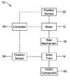
- FIG. 1is a schematic view of an illustrative but non-limiting spring return actuator
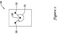
- FIG. 2is a schematic view of an illustrative HVAC component that may be actuated via the spring return actuator of FIG. 1 ;
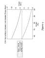
- FIG. 3is a graph showing the torque applied to a load using a constant torque motor
- FIG. 4is a graph showing the torque applied to a load using a variable torque motor.
- FIG. 5is a flow diagram showing an illustrative but non-limiting method that may be carried out using an actuator such as the spring return actuator of FIG. 1 .
- HVAC component actuatorssuch as spring return actuators. While an HVAC component actuator is described and shown as a spring return actuator, it will be appreciated that in some cases, the HVAC component actuator may not include a return spring or other biasing structure. For example, and in some instances, the HVAC component actuator may use a motor to drive an HVAC component in both directions, rather than using a motor to drive in a first direction and a return spring or other biasing structure to drive the HVAC component in a second direction. In some cases, an HVAC component actuator may include an on-board power supply such as a battery that can be used as a fail-safe in powering the motor long enough to drive an HVAC component in a desired direction in the case of a power failure.
- an HVAC component actuatormay include an on-board power supply such as a battery that can be used as a fail-safe in powering the motor long enough to drive an HVAC component in a desired direction in the case of a power failure.
- FIG. 1shows an illustrative but non-limiting example of a spring return actuator 10 .
- Spring return actuator 10may be considered as including a motor 12 .
- motor 12may be a DC motor, an AC motor, a stepper motor, or any other suitable type of motor, as desired.
- the torque output of motor 12may be adjustable by, for example, altering the current (or voltage) that is applied to motor 12 .
- the maximum output torque of the motor 12may be set by limiting or clipping the current (or voltage) that is applied to motor 12 .
- motor 12may engage with a drive train 14 .
- drive train 14may function as a transmission, taking a relatively high speed, low torque output from motor 12 and turning it into a relatively low speed, high torque output that is suitable for driving an HVAC component 16 between two or more positions.
- HVAC component 16may, for example, be an air damper, a fluid valve such as a ball valve, or the like.
- the particular gearing present within drive train 14may be customized to provide an appropriate balance of speed and torque, depending on the physical characteristics and/or requirements of HVAC component 16 .
- the drive train 14may be configured to have an appropriate speed reduction and thus provide an appropriate level of torque.
- drive train 14may provide a speed reduction of about 1000:1, about 2000:1, about 3000:1, or any other suitable speed reduction as desired.
- spring return actuator 10may include a bias mechanism 18 . While bias mechanism is schematically illustrated as being disposed between motor 12 and drive train 14 , it will be appreciated that this is not necessary in all situations. In some cases, for example, bias mechanism 18 may instead be disposed between drive train 14 and HVAC component 16 , between HVAC component 16 and a fixed bracket or duct, or at any other suitable location. Bias mechanism 18 may be any suitable structure that can provide a bias force that opposes at least one driving direction of motor 12 . In some cases, bias mechanism 18 may be a resilient material such as a rubber, a gas cylinder, a hydraulic component, or the like. In some instances, bias mechanism 18 may be one or more return springs. If, for example, motor 12 drives HVAC component 16 in a first direction, bias mechanism 18 may drive HVAC component 16 in an opposing direction.
- spring return actuator 10may include a controller 20 .
- Controller 20may, for example, monitor and/or adjust the speed of motor 12 .
- controller 20may alter the speed of motor 12 in order to slow down the motor 12 when approaching an end stop in drive train 14 and/or HVAC component 16 .
- spring return actuator 10may include one or more sensors that are in communication with controller 20 to provide controller 20 with information pertaining to the speed of motor 12 and/or the relative position of motor 12 , drive train 14 and/or HVAC component 16 .
- spring return actuator 10may include a first position sensor 22 that is disposed proximate to motor 12 and that is in communication with controller 20 as well as a second position sensor 24 that is disposed proximate to drive train 14 and that is in communication with controller 20 .
- Spring return actuator 10may include both first position sensor 22 and second position sensor 24 .
- one or both of the position sensorsmay be omitted or perhaps replaced with any other desired type of position or speed sensor, as desired.
- An optical encodermay be used as a sensor, if desired.
- first position sensor 22may be a sensor that outputs a signal related to motor rotation.
- first position sensor 22may be a Hall sensor that outputs an incremental signal that represents motor rotations, although other types of sensors may be used.
- Second position sensor 24may be a position potentiometer sensor, but this is not required. In some instances, such as if first position sensor 22 is a Hall sensor, there may be a known relationship between Hall counts and motor rotation that can be used to ascertain how many rotations motor 12 has undergone, and thus determine a position of drive train 14 . Controller 20 may rely upon both sensors, or may, in some cases, operate in accordance with a signal from first position sensor 22 as long as it is in relative agreement with a signal from second position sensor 24 .
- controller 20may alter and/or limit the current (and/or voltage) that is provided to the motor 12 in order to adjust the maximum output torque provided by the motor 12 and/or drive train 14 .
- the amplitude of the current (and/or voltage)may be controlled and/or limited.
- other characteristics of the current and/or voltagemay be altered or limited.
- PWMPulse Width Modulated
- controller 20may be programmed or otherwise configured to control the operation of motor 12 .
- a bias mechanism 18may be provided, and may include a return spring that opposes the driving force of motor 12 .
- controller 20may be configured to, for example, operate motor 12 in a manner that permits motor 12 to provide a maximum output torque at the output of the HVAC actuator that remains constant or at least substantially constant over at least a portion of a range of motion of the HVAC actuator.
- the output torquemay be constant or at least substantially constant over all or substantially all of the range of motion of HVAC actuator.
- the controller 20may provide a torque output limit at the output of the motor 12 that increases in accordance with the increasing return spring force provided by the return spring over all or substantially all of the range of motion of the HVAC actuator.
- drive train 14may have an output shaft or gear that drives the HVAC component 16 .
- the output shaft or gearmay be considered as rotating through a range of motion.
- the range of motionmay be defined not in terms of the rotation of the output shaft, but rather in terms of the rotation or other movement of HVAC component 16 in response to the rotating output shaft or gear.
- the range of motionmay be defined as the path traveled (either via the output shaft or HVAC component 16 ) between end points.
- an illustrative HVAC component 16is schematically shown as having a shaft 26 that may, for example, be driven by drive train 14 ( FIG. 1 ) as well as being connected to whatever portion of HVAC component 16 may be opened or closed. If HVAC component 16 is an air damper, shaft 26 may be connected to the damper itself. If HVAC component 16 is a fluid valve such as a ball valve, shaft 26 may engage the ball valve ball itself.
- the illustrative HVAC component 16is seen as including a first end point 28 and a second end point 30 , with a range of motion 32 defined therebetween. In some cases, first end point 28 and/or second end point 30 may represent mechanical limits of drive train 14 ( FIG. 1 ) or the HVAC component 16 . In some instances, first end point 28 and/or second end point 30 may be adjustable end points that may, for example, be set by an installer to prevent damage or set other limits to particular aspects or portions of HVAC component 16 .
- controller 20may be configured to instruct motor 12 , perhaps by controlling the current (and/or voltage) provided to motor 12 , to output to drive train 14 an amount of torque that equals or substantially equals a rated torque value plus an amount that is related to the magnitude (but opposite in direction) of the opposing torque provided to drive train 14 by bias mechanism 18 .
- the rated torquemay be a predetermined value that provides sufficient torque to sufficiently move HVAC component 16 .
- controller 20may be configured to instruct motor 12 to provide a maximum output torque that varies with the opposing torque provided by bias mechanism 18 , to thereby provide a constant or substantially constant net torque to HVAC component 16 across the range of motion 32 of the HVAC component 16 .
- controller 20may be considered as regulating motor 12 to provide a variable maximum allowed torque.
- the maximum allowed output torquemay, for example, vary with respect to position along the range of motion 32 ( FIG. 2 ).
- controller 20may be programmed with a lookup table that provides values that are related to the opposing torque provided by bias mechanism 18 at a number of different locations or positions along the range of motion 32 ( FIG. 2 ). In some instances, controller 20 may be programmed with a mathematical relationship that relates the current location of the HVAC actuator 16 and bias mechanism 18 opposing torque. It is contemplated that in some cases, controller 20 may be in communication with a sensor (not shown) that provides the controller 20 with an estimate of the actual opposing torque provided by bias mechanism 18 , but this is not required. In other cases, the controller 20 may be programmed with a lookup table that provides a value that is related to the maximum output torque of the motor 12 at a number of different locations or positions along the range of motion 32 ( FIG. 2 ).
- FIGS. 3 and 4are graphs illustrating an advantage of using controller 20 to regulate or compensate the maximum output torque provided by motor 12 across a range of motion of an HVAC actuator.
- the motoris illustrated as providing a constant output torque of 10 N ⁇ m (Newton meters).
- N ⁇ mNewton meters
- the stroke percentageis another way of identifying the current location of an HVAC actuator along the range of motion of the HVAC actuator.
- the spring forcemay be approximated by Hooke's law, which states that the spring force is proportional to elongation (or compression) relative to an equilibrium position.
- FIG. 4shows limiting the maximum output torque of the motor across the stroke length.
- the maximum torque output of the motorchanges in accordance with the opposing torque applied by the spring force.
- the motoroutputs about 5.5 N ⁇ m of torque while the torque provided by the spring force is about 0.5 N ⁇ m.
- a net torque applied to the loadsuch as HVAC component 16
- the motor torque and the opposing torque provided by the spring forceboth increase.
- the net torque applied to the loadremains essentially constant at, in this particular example, about 5 N ⁇ m.
- the drive traindoes not have to be as heavily constructed, particularly when an intervening end point is impacted.
- controller 20may have the ability to learn where end points have been set, and/or may be in communication with one or more position sensors (not illustrated) that are disposed proximate any adjustable endstops.
- first end point 28 and second end point 30may be predetermined and/or arranged or set by an installer. In some instances, the exact position of first end point 28 and/or second end point 30 may be discovered by controller 20 , such as when a blockage is encountered and motor 12 stalls, or may be detected by the aforementioned position sensors disposed proximate any adjustable endstops.
- spring return actuator 10may also encounter other points along the travel path (such as along range of motion 32 , in FIG. 2 ) that may be unexpected such as temporary blockages (e.g. ice within an air damper). It will be appreciated that, in some cases, the chance of damage occurring to the HVAC actuator increases if motor 12 is operating at full speed when an end stop or blockage is encountered.
- controller 20may be configured to save the location to a memory.
- the end stop and/or blockage locationmay be saved to permanent (e.g. non-volatile) memory.
- the locationmay be determined via one or more of first position sensor 22 or second position sensor 24 ( FIG. 1 ), or by any other suitable technique.
- controller 20may instruct motor 12 to slow down when approaching an identified blockage location or end point.
- spring return actuator 10may drive HVAC component 16 at a constant or substantially constant motor speed, other than perhaps initial startup or when approaching a known or discovered blockage or known end point. It will be appreciated that when motor 12 first starts, there may be a brief period of time while the torque output by motor 12 must overcome inertia within the motor 12 , drive train 14 and HVAC component 16 , as well as any frictional forces. When approaching a known blockage position or known end point, the speed may be reduced, but perhaps not instantly, as motor 12 , drive train 14 and/or HVAC component 16 may have a certain amount of momentum.
- the amount that the motor speed drops when approaching a blockage or end stop positionmay be programmed into controller 20 , and may depend on the physical characteristics of motor 12 , drive train 14 , HVAC component 16 and the like.
- motor 12may have a normal speed of about 3000 rpm. When approaching a blockage position, motor 12 may drop its speed to about 1000 rpm. Again, merely to illustrate but not limit, motor 12 may reduce its speed when, for example, HVAC actuator 16 is about 5 degrees away from the blockage or end point position. This parameter may also be subject to change, depending on the physical characteristics of the individual components.
- controller 20may instruct motor 12 to slow down to a new slower speed that represents a particular fraction of its original speed when drive train 14 is at a particular rotational position relative to the stored or preprogrammed blockage or end point position. Consequently, drive train 14 may be moving more slowly when the blockage or end point is encountered, thereby lessening potential damage to drive train 14 , and in some cases, allowing the motor, drive train and/or HVAC component to be manufactured in a less robust manner. It will be appreciated that by slowing down just before reaching a stored blockage and/or end point, rather than simply stopping, HVAC component 16 may be able to be actuated closer to an actual end point, especially if a discovered blockage position has disappeared or has otherwise been overcome. For example, in an air damper, there may be a temporary blockage caused by ice. Once the ice melts, the temporary blockage may disappear and thus drive train 14 is not stopped unnecessarily.
- FIG. 5is a flow diagram showing an illustrative method that may be carried out using an actuator as discussed herein. While FIG. 5 pertains to an actuator that drives the motor in both directions (no return spring), it will be appreciated that this method may also be carried out using a spring return actuator. In FIG. 5 , there is a separate flow path for clockwise rotation and counterclockwise rotation. If the actuator includes bias mechanism 18 ( FIG. 1 ), it will be appreciated that one flow path will pertain to driving HVAC component 16 ( FIG. 1 ) from a closed position to an open position (or visa-versa) while the other flow path may not be carried out because bias mechanism 18 , rather than motor 12 , may be used to drive HVAC component 16 from the open position to the closed position.
- controlbegins at decision block 34 , where a controller such as controller 20 ( FIG. 1 ) determines if the motor is driving in a clockwise direction or a counterclockwise direction.
- a controllersuch as controller 20 ( FIG. 1 ) determines if the motor is driving in a clockwise direction or a counterclockwise direction.
- One of these directionsmay, for example, drive HVAC component 16 ( FIG. 1 ) towards an open position while the other direction may, for example, drive HVAC component 16 towards a closed position.
- the actuatorincludes a bias mechanism such as bias mechanism 18 ( FIG. 1 ) only one side of this flow diagram may be carried out.
Landscapes
- Engineering & Computer Science (AREA)
- General Engineering & Computer Science (AREA)
- Mechanical Engineering (AREA)
- Control Of Electric Motors In General (AREA)
Abstract
Description
Claims (21)
Priority Applications (5)
| Application Number | Priority Date | Filing Date | Title |
|---|---|---|---|
| US12/273,413US8084982B2 (en) | 2008-11-18 | 2008-11-18 | HVAC actuator with output torque compensation |
| EP09828102.5AEP2356523B1 (en) | 2008-11-18 | 2009-11-17 | Hvac actuator with output torque compensation |
| PCT/US2009/064754WO2010059608A2 (en) | 2008-11-18 | 2009-11-17 | Hvac actuator with output torque compensation |
| CN2009801546157ACN102282514B (en) | 2008-11-18 | 2009-11-17 | Heating ventilation and air-condition actuator with output torque compensation |
| EP19157574.5AEP3528061A1 (en) | 2008-11-18 | 2009-11-17 | Hvac actuator with output torque compensation |
Applications Claiming Priority (1)
| Application Number | Priority Date | Filing Date | Title |
|---|---|---|---|
| US12/273,413US8084982B2 (en) | 2008-11-18 | 2008-11-18 | HVAC actuator with output torque compensation |
Publications (2)
| Publication Number | Publication Date |
|---|---|
| US20100123421A1 US20100123421A1 (en) | 2010-05-20 |
| US8084982B2true US8084982B2 (en) | 2011-12-27 |
Family
ID=42171469
Family Applications (1)
| Application Number | Title | Priority Date | Filing Date |
|---|---|---|---|
| US12/273,413Active2030-03-29US8084982B2 (en) | 2008-11-18 | 2008-11-18 | HVAC actuator with output torque compensation |
Country Status (4)
| Country | Link |
|---|---|
| US (1) | US8084982B2 (en) |
| EP (2) | EP3528061A1 (en) |
| CN (1) | CN102282514B (en) |
| WO (1) | WO2010059608A2 (en) |
Cited By (19)
| Publication number | Priority date | Publication date | Assignee | Title |
|---|---|---|---|---|
| US20100060219A1 (en)* | 2008-09-08 | 2010-03-11 | Emerson Electric Co. | Blower motor for hvac systems |
| US20100253270A1 (en)* | 2009-04-06 | 2010-10-07 | Belimo Holding Ag | Method and devices for driving a damper |
| US8487580B2 (en)* | 2008-09-08 | 2013-07-16 | Nidec Motor Corporation | Blower motor for HVAC systems |
| US20140370795A1 (en)* | 2013-06-13 | 2014-12-18 | Ford Global Technologies, Llc | Vehicle speed controlled active grille shutter system |
| US8922140B2 (en) | 2011-11-09 | 2014-12-30 | Honeywell International Inc. | Dual potentiometer address and direction selection for an actuator |
| US8972064B2 (en) | 2011-11-09 | 2015-03-03 | Honeywell International Inc. | Actuator with diagnostics |
| US9106171B2 (en) | 2013-05-17 | 2015-08-11 | Honeywell International Inc. | Power supply compensation for an actuator |
| US9168828B2 (en) | 2013-05-21 | 2015-10-27 | Johnson Electric S.A. | Actuator with progressive gear |
| US20150333669A1 (en)* | 2012-06-26 | 2015-11-19 | Johnson Controls Technology Company | Hvac actuator with soft stall control |
| US20160156299A1 (en)* | 2012-06-26 | 2016-06-02 | Johnson Controls Technology Company | Hvac actuator with automatic end stop recalibration |
| US20160159477A1 (en)* | 2014-05-09 | 2016-06-09 | Purdue Research Foundation | Resonance motor direct drive flapping wing micro air vehicle system |
| US9509242B2 (en) | 2012-06-26 | 2016-11-29 | Johnson Controls Technology Company | Systems and method for speed and torque control of a DC motor |
| US10199962B2 (en) | 2015-03-18 | 2019-02-05 | Johnson Controls Technology Company | Plug and play universal input actuator |
| US10550952B1 (en) | 2018-09-07 | 2020-02-04 | Honeywell International Inc. | Method and apparatus for parking a return spring HVAC actuator at a closed position |
| US10634379B2 (en) | 2017-09-28 | 2020-04-28 | Honeywell International Inc. | Actuators with condition tracking |
| US10900582B2 (en)* | 2016-09-23 | 2021-01-26 | Taco, Inc. | High voltage high efficiency valve |
| US11224777B2 (en) | 2019-02-25 | 2022-01-18 | Honeywell International Inc. | Fire and smoke actuator with temperature-dependent operating speed |
| US20220065476A1 (en)* | 2020-09-02 | 2022-03-03 | Johnson Controls Tyco IP Holdings LLP | Incremental actuator with feedback control diagnostics |
| US12431621B2 (en) | 2023-01-26 | 2025-09-30 | Honeywell International Inc. | Compact dual band antenna |
Families Citing this family (5)
| Publication number | Priority date | Publication date | Assignee | Title |
|---|---|---|---|---|
| US9667188B2 (en) | 2011-04-05 | 2017-05-30 | Belimo Holding Ag | Flow control actuator |
| US20130049644A1 (en)* | 2011-08-22 | 2013-02-28 | Hansen Corporation | Actuator for an airflow damper |
| US9845963B2 (en) | 2014-10-31 | 2017-12-19 | Honeywell International Inc. | Economizer having damper modulation |
| US10698399B2 (en)* | 2016-04-12 | 2020-06-30 | Johnson Controls Technology Company | HVAC system with equipment failure prediction |
| US20170295058A1 (en) | 2016-04-12 | 2017-10-12 | Johnson Controls Technology Company | Devices and methods for network integration of an hvac device |
Citations (271)
| Publication number | Priority date | Publication date | Assignee | Title |
|---|---|---|---|---|
| US23902A (en) | 1859-05-10 | Butterfly-valve | ||
| US105925A (en) | 1870-08-02 | Improvement in stop-plates for hydrants | ||
| US2414947A (en) | 1944-09-18 | 1947-01-28 | Doyle Mfg Corp | Engine governor |
| US2761647A (en) | 1951-05-02 | 1956-09-04 | Ivan V Zeck | Valve for internal combustion engine carburetor |
| CH320865A (en) | 1953-12-16 | 1957-04-15 | Danfoss Ved Ing Mads Clausen F | Thermostatically controlled radiator valve |
| US2965354A (en) | 1957-08-26 | 1960-12-20 | Grove Valve & Regulator Co | Valve construction |
| US3569810A (en) | 1968-11-20 | 1971-03-09 | Allis Chalmers Mfg Co | Pulse width modulator with pulse width limiting |
| US3579072A (en) | 1967-11-03 | 1971-05-18 | Rank Organisation Ltd | Servo position control including integral control in foreward and feedback controls |
| US3742267A (en) | 1969-09-27 | 1973-06-26 | Papst Motoren Kg | Fan arrangement having automatic control capability |
| US3750780A (en) | 1972-01-21 | 1973-08-07 | Gen Motors Corp | Brake operated throttle override device |
| US3807709A (en) | 1970-09-24 | 1974-04-30 | Nippon Denso Co | Carburetor |
| US3839662A (en) | 1973-05-08 | 1974-10-01 | Telemecanique Electrique | Motorized valve control |
| US3931557A (en) | 1974-11-13 | 1976-01-06 | General Motors Corporation | DC Motor stall protection circuit |
| US3937974A (en) | 1974-08-30 | 1976-02-10 | General Electric Company | Starter-generator utilizing phase controlled rectifiers to drive a dynamoelectric machine as a brushless DC motor in the starting mode with starter position sense variation with speed |
| US3967227A (en) | 1975-01-10 | 1976-06-29 | Texas Instruments Incorporated | Actuator system with ambient temperature compensation |
| US4027216A (en) | 1975-08-01 | 1977-05-31 | Portec, Inc. | Control device for a synchronous motor |
| US4038589A (en) | 1975-11-20 | 1977-07-26 | Westinghouse Electric Corporation | Controlled post-synchronizing on brushless synchronous motors |
| US4086519A (en) | 1977-02-25 | 1978-04-25 | Electro-Craft Corporation | Hall effect shaft angle position encoder |
| US4090434A (en) | 1977-03-07 | 1978-05-23 | Connor Engineering & Manufacturing, Inc. | Variable induction apparatus with a primary fluid flow controlled induction damper |
| US4099704A (en) | 1975-12-26 | 1978-07-11 | Hitachi, Ltd. | Vacuum valve apparatus |
| US4139807A (en) | 1977-07-12 | 1979-02-13 | Sundstrand Corporation | Rotor short-circuiting switch |
| US4177716A (en) | 1978-02-21 | 1979-12-11 | Gerald J. Bowe | Automatic energy saver and fire damper for exhaust systems |
| US4227664A (en) | 1979-04-23 | 1980-10-14 | Sperry Corporation | Stall current limiter for servo drive systems |
| US4251024A (en) | 1978-02-23 | 1981-02-17 | Paragon Resources, Inc. | Automatic vent damper |
| US4286303A (en) | 1979-03-19 | 1981-08-25 | Franklin Electric Co., Inc. | Protection system for an electric motor |
| US4292802A (en) | 1978-12-27 | 1981-10-06 | General Electric Company | Method and apparatus for increasing compressor inlet pressure |
| US4295085A (en) | 1979-05-25 | 1981-10-13 | General Electric Company | Phase lock loop commutation position control and method |
| US4311950A (en) | 1980-03-28 | 1982-01-19 | Goldin Rodion G | Excitation system for a synchronous machine |
| US4315202A (en) | 1979-04-19 | 1982-02-09 | Associated Electrical Industries Limited | Synchronous motors |
| US4322668A (en) | 1976-11-12 | 1982-03-30 | Canadian General Electric Company Ltd. | Power control of a stalling motor |
| US4337821A (en) | 1978-11-28 | 1982-07-06 | Nippondenso Co., Ltd. | Air conditioner system for automobiles |
| US4364111A (en) | 1980-05-20 | 1982-12-14 | Westran Corporation | Electronically controlled valve actuator |
| US4364004A (en) | 1980-01-29 | 1982-12-14 | Bourbeau Frank J | Self-controlled polyphase synchronous motor drive system |
| US4364301A (en) | 1979-09-21 | 1982-12-21 | Aisin Seiki Kabushiki Kaisha | Vacuum actuator |
| US4372485A (en) | 1980-12-01 | 1983-02-08 | Mccabe Francis J | Thermally activated, automatic damper and damper operator |
| US4379986A (en) | 1981-08-24 | 1983-04-12 | Marquette Metal Products Co. | Stall sensing circuit for shaded pole motors |
| US4393597A (en) | 1979-12-26 | 1983-07-19 | Societe D'applications Generales | Stabilized sighting devices for vehicles |
| US4407264A (en) | 1981-12-02 | 1983-10-04 | Pettorino Arthur J | Adjustable fresh air damper for combustion |
| US4414498A (en) | 1981-02-23 | 1983-11-08 | Advanced Semiconductor Materials Die Bonding, Inc. | Stepping motor drive circuit |
| US4422028A (en) | 1981-05-12 | 1983-12-20 | Westinghouse Electric Corp. | Brushless excitation system with a holding current resistor |
| US4423364A (en) | 1982-03-29 | 1983-12-27 | Honeywell Inc. | Electric motor damper drive with backup power pack |
| US4423362A (en) | 1982-05-19 | 1983-12-27 | General Electric Company | Electric vehicle current regulating system |
| US4424472A (en) | 1980-10-10 | 1984-01-03 | Microbo, S.A. | Programmable robot |
| US4424799A (en) | 1981-01-14 | 1984-01-10 | Patterson Tommy W | Automatic adjustable air baffle |
| US4434932A (en) | 1981-07-07 | 1984-03-06 | Nippondenso Co., Ltd. | Air-conditioner control system for automobiles |
| US4439139A (en) | 1982-02-26 | 1984-03-27 | Honeywell Inc. | Furnace stack damper control apparatus |
| US4445075A (en) | 1981-04-30 | 1984-04-24 | Rotork Controls Limited | Valve actuators |
| US4456166A (en) | 1982-02-08 | 1984-06-26 | Hitachi, Ltd. | Temperature control system for air conditioners |
| US4458583A (en) | 1981-05-08 | 1984-07-10 | Nippondenso Co., Ltd. | Air conditioner control system for automotive vehicles |
| US4473783A (en) | 1983-05-20 | 1984-09-25 | National Semiconductor Corporation | Motor control circuit |
| US4473856A (en) | 1980-12-29 | 1984-09-25 | Matsushita Electric Industrial Co., Ltd. | Overcurrent protection apparatus for DC motor |
| US4491775A (en) | 1981-10-26 | 1985-01-01 | Colin Frank Norton | Motor operating parameter sensing apparatus |
| US4501155A (en) | 1983-06-29 | 1985-02-26 | Rheometrics, Inc. | Compensated rheometer |
| US4530395A (en) | 1982-10-14 | 1985-07-23 | Parker Electronics, Inc. | Single zone HVAC controlled for operation in multiple zone arrangement |
| US4531450A (en) | 1982-10-21 | 1985-07-30 | Nihon Plast Co., Ltd. | Multi-stage actuator |
| DE3402759A1 (en) | 1984-01-27 | 1985-08-01 | Robert Bosch Gmbh, 7000 Stuttgart | CURRENT CONTROLLER FOR ELECTROMAGNETIC ACTUATORS |
| US4546293A (en) | 1982-08-24 | 1985-10-08 | Sundstrand Corporation | Motor control for a brushless DC motor |
| US4547715A (en) | 1984-07-09 | 1985-10-15 | Motorola, Inc. | Current control circuit |
| US4547720A (en) | 1982-10-08 | 1985-10-15 | Newelec Pretoria Ltd. | Induction motor start-stall detection apparatus and method |
| US4556194A (en) | 1984-11-11 | 1985-12-03 | Asahi/America Inc. | Motor operated valve |
| US4557418A (en) | 1983-12-19 | 1985-12-10 | Leemhuis Louis J | Energy conservation conditioned air system |
| US4572333A (en) | 1984-04-16 | 1986-02-25 | Honeywell Inc. | Speed governing and decoupling drive mechanism |
| US4578605A (en) | 1982-11-08 | 1986-03-25 | Ebm Elektrobau Mulfingen Gmbh & Co. | Electric motor with a system for monitoring speed |
| US4591775A (en) | 1984-02-17 | 1986-05-27 | Siemens Aktiengesellschaft | Electric synchronous machine which is excited via rotating rectifiers |
| US4591773A (en) | 1983-12-29 | 1986-05-27 | Alps Electric Co., Ltd. | Motor driving circuit for motor actuator |
| US4591774A (en) | 1981-05-21 | 1986-05-27 | Dataproducts Corporation | High performance incremental motion system using a closed loop stepping motor |
| US4608527A (en) | 1982-12-20 | 1986-08-26 | Sundstrand Corporation | Phase advance waveform generator for brushless DC actuator system controller |
| US4613798A (en) | 1985-04-01 | 1986-09-23 | Baumann Peter H | Electric-powered spring-return actuating device |
| US4618808A (en) | 1985-01-30 | 1986-10-21 | International Business Machines Corporation | Electromagnetic actuator system using stepper motor with closed loop position sensing, electronic commutation and dynamic position and anomaly correction |
| US4623826A (en) | 1984-07-31 | 1986-11-18 | John Brown Inc. | Stall protection circuit for brushless motor control |
| US4633152A (en) | 1984-11-29 | 1986-12-30 | Abex Corporation | Direct current motor controller |
| US4651068A (en) | 1984-10-01 | 1987-03-17 | Electro-Craft Corporation | Brushless motor control circuitry with optimum current vector control |
| US4656410A (en) | 1984-08-09 | 1987-04-07 | Fukuo Shibata | Construction of single-phase electric rotating machine |
| US4656407A (en) | 1985-06-14 | 1987-04-07 | A.R.A. Manufacturing Company Of Delware, Inc. | Electric motor servo control system and method |
| US4659973A (en) | 1986-04-30 | 1987-04-21 | Siemens Energy & Automation, Inc. | Brushless exciter for controlling excitation of a synchronous machine |
| US4691689A (en) | 1985-12-06 | 1987-09-08 | B. D. Wait Co. Limited | One piece adjustable damper |
| US4701839A (en) | 1984-11-09 | 1987-10-20 | International Cybernetic Corporation | Sampled data servo control system with field orientation |
| US4704569A (en) | 1986-06-20 | 1987-11-03 | Westinghouse Electric Corp. | Dynamoelectric machine excitation system with improved gate module |
| US4720792A (en) | 1984-11-26 | 1988-01-19 | Fujitsu Limited | Method and apparatus for controlling operation of a throttle |
| US4725765A (en) | 1985-11-18 | 1988-02-16 | Ford Motor Company | Method and apparatus for the protection of D.C. motors under stalled conditions |
| US4746850A (en) | 1987-02-12 | 1988-05-24 | Westinghouse Electric Corp. | Start-up system for a synchronous motor drive |
| US4751438A (en) | 1985-12-18 | 1988-06-14 | Sundstrand Corporation | Brushless DC motor control |
| US4771643A (en) | 1982-05-13 | 1988-09-20 | Honeywell Inc. | Spring return for motor driven loads |
| US4780653A (en) | 1987-03-05 | 1988-10-25 | Pulse Electronics, Inc. | Anti-stall motor drive |
| US4818908A (en) | 1985-08-12 | 1989-04-04 | Matsushita Electric Industrial Co., Ltd. | Brushless motor having phase advance |
| US4823063A (en) | 1985-04-02 | 1989-04-18 | Plessey Incorporated | Authority limiter |
| US4825138A (en) | 1986-07-10 | 1989-04-25 | Dipl. Ing. Hitzinger Gesellschaft Mbh | Brushless synchronous motor with short-circuited protective winding for the field winding of the rotor |
| US4835448A (en) | 1987-12-28 | 1989-05-30 | Sundstrand Corporation | Brushless DC motor torque control |
| US4834282A (en) | 1987-02-25 | 1989-05-30 | Abel Tenorio | Device for use with flue dampers |
| US4839579A (en) | 1987-07-10 | 1989-06-13 | Wataru Ito | Resistive steering sensor |
| US4844115A (en) | 1988-10-31 | 1989-07-04 | Bowers Rudy M | Butterfly valve |
| US4844110A (en) | 1988-06-29 | 1989-07-04 | The Phasor Corporation | Control system for remotely controlled motor operated valve |
| US4888533A (en) | 1986-04-25 | 1989-12-19 | Matsushita Electric Industrial Co Ltd | Brushless DC motor |
| US4897583A (en) | 1989-03-07 | 1990-01-30 | Sundstrand Corporation | Variable speed variable torque brushless DC motor |
| US4937508A (en) | 1989-05-12 | 1990-06-26 | Sundstrand Corporation | VSCF start system with precision voltage |
| US4939441A (en) | 1989-10-27 | 1990-07-03 | Sundstrand Corporation | Excitation system for a brushless generator having separate AC and DC exciter field windings |
| US4949021A (en) | 1988-11-14 | 1990-08-14 | Sunstrand Corporation | Variable speed constant frequency start system with selectable input power limiting |
| US4969756A (en) | 1990-03-19 | 1990-11-13 | General Motors Corporation | Motor driven actuator speed control |
| US4985666A (en) | 1988-08-30 | 1991-01-15 | Sony Corporation | Safety device for video cassette recorder |
| US5012168A (en) | 1990-02-20 | 1991-04-30 | Ford Motor Company | Method and apparatus for detecting stall current in an energized electric motor |
| US5017846A (en) | 1990-04-05 | 1991-05-21 | General Electric Company | Stall protection circuit for an electronically commutated motor |
| US5020423A (en) | 1990-07-20 | 1991-06-04 | Mestek, Inc. | Rotating blade damper with blade lock and stop mechanism |
| US5029263A (en) | 1989-10-19 | 1991-07-02 | Sundstrand Corporation | Electric start control of a VSCF system |
| US5038062A (en) | 1989-10-12 | 1991-08-06 | Shicoh Engineering Co., Ltd. | Swing-arm type linear d.c. brushless motor |
| US5047681A (en) | 1989-01-11 | 1991-09-10 | Gec Alsthom Sa | Constant power synchronous motor with microprocessor control |
| US5053688A (en) | 1989-03-07 | 1991-10-01 | Sundstrand Corporation | Feedback circuit for eliminating DC offset in drive current of an AC motor |
| US5053689A (en) | 1986-07-22 | 1991-10-01 | University Of Texas At Austin | Method and apparatus for improving performance of AC machines |
| US5081405A (en) | 1991-04-01 | 1992-01-14 | Honeywell Inc. | Electrical actuator with means for preventing dither at a limit switch |
| US5087866A (en) | 1991-05-22 | 1992-02-11 | Lucas Industries | Temperature compensating circuit for LVDT and control system |
| US5096156A (en) | 1991-04-22 | 1992-03-17 | Beutler Heating & Air Conditioning, Inc. | Motorized damper apparatus |
| US5097189A (en) | 1989-07-18 | 1992-03-17 | Canon Kabushiki Kaisha | Recording apparatus |
| US5113125A (en) | 1991-05-01 | 1992-05-12 | Westinghouse Electric Corp. | AC drive with optimized torque |
| US5117900A (en) | 1991-04-15 | 1992-06-02 | American Standard Inc. | System for providing individual comfort control |
| US5132602A (en) | 1990-10-02 | 1992-07-21 | Calsonic International, Inc. | Actuator positioning apparatus |
| US5139230A (en) | 1991-07-31 | 1992-08-18 | Asahi/America, Inc. | Travel stop assembly for valves |
| US5151063A (en) | 1989-10-03 | 1992-09-29 | Zexel Corporation | Air conditioning distribution system |
| US5153493A (en) | 1991-02-04 | 1992-10-06 | Barber-Colman Company | Non-bridge type electronic actuator control |
| US5168202A (en) | 1991-08-30 | 1992-12-01 | Platt Saco Lowell Corporation | Microprocessor control of electric motors |
| US5169121A (en) | 1990-12-24 | 1992-12-08 | Mitsubishi Electronics America, Inc. | Damper control mechanism |
| DE4218782A1 (en) | 1992-06-06 | 1993-01-14 | Zahnradfabrik Friedrichshafen | METHOD FOR CONTROLLING ELECTRICAL, CURRENT-CONTROLLED ACTUATORS |
| US5182498A (en) | 1991-11-27 | 1993-01-26 | Honeywell Inc. | Spring return rotary actuator |
| US5200661A (en) | 1989-12-15 | 1993-04-06 | Shramo Daniel J | Slotless, brushless, large air gap electric motor |
| US5251815A (en) | 1992-12-18 | 1993-10-12 | American Standard Inc. | Self powered and balancing air damper |
| US5274315A (en) | 1991-06-18 | 1993-12-28 | Montenero O.M.T.P. Officina Meccanica Di Finocchi Paolo & C. Snc | Card web comb driving system in machines for the textile industry |
| US5291106A (en) | 1992-11-23 | 1994-03-01 | General Motors Corporation | Single current regulator for controlled motoring and braking of a DC-fed electric motor |
| DE4234421A1 (en) | 1992-10-13 | 1994-04-14 | Bosch Gmbh Robert | Device for the current-controlled control of several actuators by means of a control computer |
| US5363025A (en) | 1992-12-30 | 1994-11-08 | Honeywell Inc. | Actuator employing unidirectional motor for bidirectional rotational positioning |
| US5367236A (en) | 1992-09-21 | 1994-11-22 | Pitney Bowes Inc. | DC motor stall-detection system |
| US5373205A (en) | 1992-12-29 | 1994-12-13 | Cincinnati Milacron Inc. | Method and apparatus for limiting motor current |
| US5384527A (en) | 1993-05-12 | 1995-01-24 | Sundstrand Corporation | Rotor position detector with back EMF voltage estimation |
| US5406186A (en) | 1994-01-25 | 1995-04-11 | Sundstrand Corporation | One switch multi-phase modulator |
| US5409194A (en) | 1990-04-12 | 1995-04-25 | Crouzet Electromenager | Variable flow electrically controlled valve |
| US5416397A (en) | 1993-10-04 | 1995-05-16 | Ford Motor Company | Linear motor control system and method of use |
| US5416652A (en) | 1990-10-12 | 1995-05-16 | Servo Track Writer Corporation | Apparatus for, and methods of, recording signals in tracks on a memory member without a reference index |
| US5430362A (en) | 1993-05-12 | 1995-07-04 | Sundstrand Corporation | Engine starting system utilizing multiple controlled acceleration rates |
| US5429090A (en) | 1994-02-28 | 1995-07-04 | Coltec Industries Inc. | Fail safe throttle positioning system |
| US5440486A (en) | 1993-06-01 | 1995-08-08 | Chrysler Corporation | Predictive electric motor positioning device, normal operating system therefor |
| US5449986A (en) | 1994-04-21 | 1995-09-12 | Dozor; David M. | Linearizing decoupling controller for electric motors |
| US5450999A (en) | 1994-07-21 | 1995-09-19 | Ems Control Systems International | Variable air volume environmental management system including a fuzzy logic control system |
| US5461293A (en) | 1993-05-12 | 1995-10-24 | Sundstrand Corporation | Rotor position detector |
| US5467808A (en) | 1993-01-14 | 1995-11-21 | Eclipse Blinds Limited | Blind or curtain suspension system |
| US5488286A (en) | 1993-05-12 | 1996-01-30 | Sundstrand Corporation | Method and apparatus for starting a synchronous machine |
| US5493200A (en) | 1993-05-12 | 1996-02-20 | Sundstrand Corporation | Control for a brushless generator |
| US5495163A (en) | 1993-05-12 | 1996-02-27 | Sundstrand Corporation | Control for a brushless generator operable in generating and starting modes |
| US5495162A (en) | 1993-05-12 | 1996-02-27 | Sundstrand Corporation | Position-and-velocity sensorless control for starter generator electrical system using generator back-EMF voltage |
| US5497326A (en) | 1994-08-03 | 1996-03-05 | The Cherry Corporation | Intelligent commutation pulse detection system to control electric D.C. motors used with automobile accessories |
| US5514947A (en) | 1995-01-31 | 1996-05-07 | National Semiconductor Corporation | Phase lead compensation circuit for an integrated switching regulator |
| US5513611A (en) | 1993-07-22 | 1996-05-07 | Societe D'applications Generales D'electricite Et De Mecanique (Sagem) | Throttle control system with motor linkage and position control |
| US5517415A (en) | 1994-10-26 | 1996-05-14 | Trw Inc. | Method and apparatus for detecting a motor stall condition in an electric assist steering system |
| US5519295A (en) | 1994-04-06 | 1996-05-21 | Honeywell Inc. | Electrically operated actuator having a capacitor storing energy for returning the actuator to a preferred position upon power failure |
| US5565750A (en) | 1995-08-30 | 1996-10-15 | The Louis Allis Company | Apparatus for applying field excitation to a synchronous electric motor |
| US5567874A (en) | 1994-05-24 | 1996-10-22 | Nippondenso Co., Ltd. | Rotary position detecting device |
| US5587641A (en) | 1988-12-05 | 1996-12-24 | Sundstrand Corporation | VSCF start system with precise voltage control |
| US5594322A (en) | 1993-05-12 | 1997-01-14 | Sundstrand Corporation | Starter/generator system with variable-frequency exciter control |
| US5610457A (en) | 1994-02-07 | 1997-03-11 | Kabushiki Kaisha Sankyo Seiki Seisakusho | Brushless motor with hall elements for controlling drive circuit and for detecting a position of rotor by use of magnetic flux varying means |
| US5617001A (en) | 1995-02-13 | 1997-04-01 | Texas Instruments Incorporated | A.C. motor starting control circuit utilizing triggerable semiconductor switching device |
| US5619085A (en) | 1989-12-15 | 1997-04-08 | Shramo; Daniel J. | Slotless, brushless, large air-gap electric motor |
| US5656911A (en) | 1994-12-27 | 1997-08-12 | Fuji Electric Company | Circuit for driving permanent-magnet synchronous motor using proportional controller |
| US5677605A (en) | 1989-08-22 | 1997-10-14 | Unique Mobility, Inc. | Brushless DC motor using phase timing advancement |
| US5703473A (en) | 1996-01-02 | 1997-12-30 | Cherry Semiconductor Corporation | Programmable PWM output voltage independent of supply |
| US5710498A (en) | 1994-12-06 | 1998-01-20 | Trinova Corporation | Method and apparatus for friction compensation |
| US5710755A (en) | 1993-11-15 | 1998-01-20 | Pitney Bowes | Communication system for control applications |
| US5723918A (en) | 1996-03-08 | 1998-03-03 | Honeywell Inc. | Bi-directional actuator using a random direction AC motor |
| US5740880A (en) | 1995-12-07 | 1998-04-21 | Ford Global Technologies, Inc. | Speed tracking of induced armature field in electric power assisted steering |
| US5744921A (en) | 1996-05-02 | 1998-04-28 | Siemens Electric Limited | Control circuit for five-phase brushless DC motor |
| US5760707A (en) | 1993-06-23 | 1998-06-02 | Kabushiki Kaisha Sankyo Seiki Seisakusho | Method of transmitting multiple serial signals |
| US5767643A (en) | 1996-02-02 | 1998-06-16 | Siliconix Incorporated | Commutation delay generator for a multiphase brushless DC motor |
| US5777447A (en) | 1995-05-29 | 1998-07-07 | Nippondenso Co., Ltd. | Control apparatus for brushless DC motor |
| US5775415A (en) | 1993-07-07 | 1998-07-07 | Nippondenso Co., Ltd. | Air conditioning system |
| US5793180A (en) | 1996-05-22 | 1998-08-11 | Sgs-Thomson Microelectronics S.R.L. | Fully digital drive system for brushless motor with voltage or current profiles read from a digital memory |
| US5796194A (en) | 1996-07-15 | 1998-08-18 | General Electric Company | Quadrature axis winding for sensorless rotor angular position control of single phase permanent magnet motor |
| US5798196A (en) | 1995-07-05 | 1998-08-25 | Nikon Corporation | Pattern transfer method utilizing distribution condition evaluation by charged particle beam |
| US5804696A (en) | 1992-10-05 | 1998-09-08 | Fisher Controls International, Inc. | Electro-pneumatic converter calibration |
| US5815381A (en) | 1997-06-06 | 1998-09-29 | Burr-Brown Corporation | Single-barrier closed loop DC-to-DC converter and method |
| US5814962A (en) | 1995-06-08 | 1998-09-29 | Minolta Co., Ltd. | Servo controller |
| US5835302A (en) | 1991-07-31 | 1998-11-10 | Seagate Technology, Inc. | Compensating for variations in torque capability of voice coil motors |
| US5850130A (en) | 1996-04-19 | 1998-12-15 | Matsushita Electric Industrial Co., Ltd. | Driving apparatus for a brushless motor and rotor position detecting apparatus for the motor |
| US5859518A (en) | 1997-12-22 | 1999-01-12 | Micro Linear Corporation | Switched reluctance motor controller with sensorless rotor position detection |
| US5874796A (en) | 1995-02-10 | 1999-02-23 | Petersen; Christian C. | Permanent magnet D.C. motor having a radially-disposed working flux gap |
| US5876014A (en) | 1995-09-13 | 1999-03-02 | Sankyo Seiki Mfg Co., Ltd. | Motor damper |
| US5912542A (en) | 1997-03-10 | 1999-06-15 | Universal Instruments Corporation | Variable load inductance compensation for motor drive circuits |
| US5912543A (en) | 1995-11-16 | 1999-06-15 | Deutsche Thomson-Brandt Gmbh | Circuit having a digital controller for operation of a synchronous T motor |
| US5921277A (en) | 1997-04-24 | 1999-07-13 | Bernal; Richard G. | Air duct damper |
| US5923728A (en) | 1997-05-09 | 1999-07-13 | Matsushita Electric Industrial Co., Ltd. | Motor controller |
| US5964455A (en) | 1997-06-13 | 1999-10-12 | Lord Corporation | Method for auto-calibration of a controllable damper suspension system |
| US5970997A (en) | 1995-02-15 | 1999-10-26 | Johnson Service Company | Smart actuator control |
| US5986369A (en) | 1997-08-19 | 1999-11-16 | Siemens Building Technologies, Inc. | Actuator having piezoelectric braking element |
| US5983890A (en) | 1998-01-09 | 1999-11-16 | Canadian Gas Research Institute | Fireplace having multi-zone heating control |
| US5990643A (en) | 1998-07-24 | 1999-11-23 | Advanced Motion Controls, Inc. | Sensorless commutation position detection for brushless D.C. motors |
| US5995710A (en) | 1998-07-24 | 1999-11-30 | Advanced Motion Controls, Inc. | Speed control for brushless DC motors |
| US6002234A (en) | 1995-06-05 | 1999-12-14 | Kollmorgen Corporation | System and method for controlling brushless permanent magnet motors |
| US6049194A (en) | 1997-07-25 | 2000-04-11 | Kokusan Denki Co., Ltd. | Generating apparatus including magneto acting as power supply |
| US6051948A (en) | 1998-11-13 | 2000-04-18 | Honeywell Inc. | Bidirectional positioning actuator with limited positioning range |
| US6061258A (en) | 1997-08-11 | 2000-05-09 | Stmicroelectronics S.R.L. | Monitoring of current in an inductive load, PWM driven through a bridge stage |
| US6075332A (en) | 1998-05-14 | 2000-06-13 | Mccann; Roy A. | Predictive conductive angle motor control system for brake-by-wire application |
| US6076368A (en) | 1997-02-05 | 2000-06-20 | Emerson Electric Co. | Electrically operated fluid control device |
| US6078204A (en) | 1996-12-19 | 2000-06-20 | Texas Instruments Incorporated | High current drain-to-gate clamp/gate-to-source clamp for external power MOS transistors |
| US6078158A (en) | 1998-12-04 | 2000-06-20 | International Business Machines Corporation | Disk drive motor spin-up control |
| US6084365A (en) | 1999-04-29 | 2000-07-04 | Siemens Building Technologies, Inc. | Actuator having timer-controlled power switching device |
| EP0895346A3 (en) | 1997-07-31 | 2000-08-02 | Honeywell Inc. | Drive circuit and method for an electric actuator with spring return |
| US6105927A (en) | 1993-06-24 | 2000-08-22 | Zelczer; Alex | Fluid flow control damper assembly and method |
| US6114827A (en) | 1996-12-30 | 2000-09-05 | Plaset Spa | Device for controlling a synchronous electric motor with a permanent magnet rotor |
| US6140626A (en) | 1998-04-23 | 2000-10-31 | Turbochef Technologies, Inc. | System for rapid air temperature modification in a recycling oven |
| US6164623A (en) | 1998-06-11 | 2000-12-26 | Aisan Kogyo Kabushiki Kaisha | Throttle valve control device |
| US6181091B1 (en) | 1999-07-22 | 2001-01-30 | International Business Machines Corporation | Apparatus and method for control of a multi-pole brushless DC motor in the event of saturation detection |
| US6181557B1 (en) | 1999-10-29 | 2001-01-30 | Motorola, Inc. | Electronic component, method of cooling, and damper therefor |
| US6198243B1 (en) | 1999-02-23 | 2001-03-06 | Johnson Controls Technology Co. | Method for automatically determining range of movement of an electromechanical actuator |
| US6222333B1 (en) | 1999-12-10 | 2001-04-24 | Texas Instruments Incorporated | DC brushless motor controller apparatus and method |
| US6236179B1 (en) | 2000-02-21 | 2001-05-22 | Lockheed Martin Energy Research Corporation | Constant power speed range extension of surface mounted PM motors |
| US6246232B1 (en) | 1999-01-08 | 2001-06-12 | Alps Electric Co., Ltd. | Rotation sensor for generating electric signals corresponding to turning angle and turning direction of detection target |
| US6244564B1 (en) | 2000-02-10 | 2001-06-12 | Kabushuki Kaisha Sankyo Seiki Seisakusho | Motor-type damper unit |
| US6271641B1 (en) | 1999-03-29 | 2001-08-07 | Matsushita Electric Industrial Co., Ltd. | Step motor driving device |
| US6279374B1 (en) | 1998-04-13 | 2001-08-28 | Smc Kabushiki Kaisha | Compensating method and compensating apparatus for positioner |
| JP2001258288A (en) | 2000-03-13 | 2001-09-21 | Hino Motors Ltd | Drive control circuit for actuator |
| US6307336B1 (en) | 1999-09-27 | 2001-10-23 | Mts Systems Corporation | Closed loop control of PWM duty cycle |
| US6313601B1 (en) | 1999-06-14 | 2001-11-06 | Teac Corporation | Speed control of a motor |
| US6318966B1 (en) | 1999-04-06 | 2001-11-20 | York International Corporation | Method and system for controlling a compressor |
| US6324085B2 (en) | 1999-12-27 | 2001-11-27 | Denso Corporation | Power converter apparatus and related method |
| US6326758B1 (en) | 1999-12-15 | 2001-12-04 | Reliance Electric Technologies, Llc | Integrated diagnostics and control systems |
| US6329777B1 (en) | 1998-11-18 | 2001-12-11 | Denso Corporation | Motor drive control apparatus and method having motor current limit function upon motor lock |
| US6348752B1 (en) | 1992-04-06 | 2002-02-19 | General Electric Company | Integral motor and control |
| JP2002070588A (en) | 2000-09-04 | 2002-03-08 | Hitachi Ltd | Electronic control throttle device |
| US6364211B1 (en) | 2000-08-30 | 2002-04-02 | Saleh A. Saleh | Wireless damper and duct fan system |
| US6369540B1 (en) | 2000-11-21 | 2002-04-09 | Honeywell International Inc. | Bypass circuit for use in DC brush motor control |
| US6367337B1 (en) | 2000-05-03 | 2002-04-09 | Cts Corporation | Non-contacting sensor for measuring relative displacement between two rotating shafts |
| US6373207B1 (en) | 2000-07-11 | 2002-04-16 | Kalish Inc. | Braking system for a DC motor |
| US6373211B1 (en) | 1999-09-17 | 2002-04-16 | Delphi Technologies, Inc. | Extended speed range operation of permanent magnet brushless machines using optimal phase angle control in the voltage mode operation |
| US6407524B1 (en) | 1998-12-24 | 2002-06-18 | Nsk Ltd. | Control apparatus for an electrical power steering apparatus |
| US6418891B2 (en) | 2000-03-13 | 2002-07-16 | Walbro Japan, Inc. | Internal combustion engine |
| US6446539B1 (en) | 2000-12-14 | 2002-09-10 | Leopold J. Niessen | Dual end stop actuator and method |
| US6495981B2 (en) | 2001-02-12 | 2002-12-17 | Johnson Controls Technology Company | Motorized actuator with a variable stall level |
| US6508072B1 (en) | 1998-10-26 | 2003-01-21 | Toshiba Carrier Corporation | Air conditioner outdoor unit drive control unit |
| US6524209B2 (en) | 2000-10-17 | 2003-02-25 | Harmonic Drive Systems, Inc. | Absolute sensor |
| US6549871B1 (en) | 2001-05-03 | 2003-04-15 | Delphi Technologies, Inc. | Current estimation for an electric machine |
| US6548981B1 (en) | 1999-02-10 | 2003-04-15 | Sony Corporation | Actuator |
| US6557826B2 (en) | 2001-09-17 | 2003-05-06 | Michael A. Moore | Low leakage butterfly damper |
| US6577978B1 (en) | 1998-03-20 | 2003-06-10 | Sensors & Software Inc. | Microprocessor and microcontroller stabilized geophysical instruments |
| US6577097B2 (en) | 2001-08-13 | 2003-06-10 | Delphi Technologies, Inc. | Method and system for controlling a synchronous machine using a changeable cycle-conduction angle |
| US6580235B2 (en) | 2000-07-17 | 2003-06-17 | Johnson Controls Automotive Electronics | Electric motor with two modes of power supply switching |
| US6593716B1 (en) | 2000-11-21 | 2003-07-15 | Honeywell International Inc. | Circuit using current limiting to reduce power consumption of actuator with DC brush motor |
| US6605912B1 (en) | 1998-06-25 | 2003-08-12 | Delphi Technologies, Inc. | Method for controlling a permanent magnet motor |
| US6626002B1 (en) | 1998-08-31 | 2003-09-30 | Hitachi, Ltd. | Controller for PWM/PAM motor, air conditioner, and method of motor control |
| US6631781B2 (en) | 1999-08-17 | 2003-10-14 | Trw Lucas Varity Electric Steering, Ltd. | Method and apparatus for controlling an electric powered assisted steering system using an adaptive blending torque filter |
| US6647329B2 (en) | 2000-04-07 | 2003-11-11 | Delphi Technologies, Inc. | Damping of voltage-controlled brushless motors for electric power steering systems |
| US6655652B2 (en) | 2000-05-19 | 2003-12-02 | Siemens Aktiengesellschaft | Position controller for a drive-actuated valve having inherent safety design |
| US6683427B2 (en) | 2001-09-26 | 2004-01-27 | S.N.R. Roulements | Device for controlling an electronically commutated motor |
| US6686713B2 (en) | 2001-09-26 | 2004-02-03 | S.N.R. Roulements | Pulse-controlled electric power-assisted steering system |
| US6694287B2 (en) | 2001-08-30 | 2004-02-17 | Delphi Technologies, Inc. | Phase angle diagnostics for sinusoidal controlled electric machine |
| US6732438B2 (en) | 2002-04-02 | 2004-05-11 | Delphi Technologies, Inc. | Rotary position sensor |
| US6741048B2 (en) | 2001-09-26 | 2004-05-25 | S.N.R. Roulements | Pulse-controlled electronically commutated motor |
| US6791219B1 (en) | 2003-06-18 | 2004-09-14 | Bvr Technologies Company | Contactless electro-mechanical actuator with coupled electronic motor commutation and output position sensors |
| US6798635B2 (en) | 2000-07-28 | 2004-09-28 | Swedish Control Systems Aktiebolag | Method and arrangement for determining the position of an electromagnetic actuator |
| US6801011B2 (en) | 2001-03-26 | 2004-10-05 | Kabushiki Kaisha Yaskawa Denki | Magnetic pole position estimating method and control apparatus for synchronous motor |
| US20040211200A1 (en)* | 2003-04-24 | 2004-10-28 | Mcmillan Scott D. | Current control loop for actuator and method |
| US6812667B2 (en) | 2002-07-15 | 2004-11-02 | Matsushita Electric Industrial Co., Ltd. | Motor driver |
| US6826499B2 (en) | 2001-10-01 | 2004-11-30 | Delphi Technologies, Inc. | Method and apparatus for calibrating and initializing an electronically commutated motor |
| US6828752B2 (en) | 2002-09-25 | 2004-12-07 | Hitachi, Ltd. | Driving equipment and semiconductor equipment for alternating-current motor |
| US6828919B1 (en) | 2000-01-11 | 2004-12-07 | American Superconductor Corporation | Exciter assembly telemetry |
| US20050034539A1 (en) | 2003-08-14 | 2005-02-17 | Tan Leeling | Motor torque variation compensation |
| US6874468B2 (en) | 2003-01-20 | 2005-04-05 | Mitsubishi Denki Kabushiki Kaisha | Throttle valve control device |
| US6900613B2 (en) | 2002-12-03 | 2005-05-31 | Sanden Corporation | Motor control apparatus |
| US6900607B2 (en) | 2001-08-17 | 2005-05-31 | Delphi Technologies, Inc. | Combined feedforward and feedback parameter estimation for electric machines |
| US6911794B2 (en) | 2003-05-08 | 2005-06-28 | Wavecrest Laboratories, Llc | Precision adaptive motor control in cruise control system having various motor control schemes |
| US6914399B2 (en) | 2002-07-09 | 2005-07-05 | Delphi Technologies | Active deadtime control for improved torque ripple performance in electric machines |
| US6954044B2 (en) | 2003-12-11 | 2005-10-11 | Honeywell International Inc. | Electric motor with speed control |
| US7188481B2 (en) | 2002-10-30 | 2007-03-13 | Honeywell International Inc. | Adjustable damper actuator |
| US7265512B2 (en) | 2005-08-30 | 2007-09-04 | Honeywell International Inc. | Actuator with feedback for end stop positioning |
| US20080051024A1 (en) | 2006-08-25 | 2008-02-28 | Siemens Building Technologies, Inc. | Damper actuator assembly with speed control |
| US7446494B2 (en) | 2006-10-10 | 2008-11-04 | Honeywell International Inc. | HVAC actuator having torque compensation |
| US20080303475A1 (en)* | 2007-06-07 | 2008-12-11 | Patel Nitinkumar R | Method and system for torque control in permanent magnet machines |
| US7637245B2 (en) | 2005-10-20 | 2009-12-29 | Denso Corporation | Method and system for controlling an actuator to rotate a valve |
Family Cites Families (6)
| Publication number | Priority date | Publication date | Assignee | Title |
|---|---|---|---|---|
| JPH112147A (en)* | 1997-06-12 | 1999-01-06 | Nissan Motor Co Ltd | Engine intake air volume adjustment device |
| JPH11311133A (en)* | 1998-04-27 | 1999-11-09 | Aisin Seiki Co Ltd | Throttle valve control device |
| US6367740B1 (en)* | 2000-05-16 | 2002-04-09 | The Boeing Company | Air foil having a hybrid leading edge construction |
| US6979965B2 (en)* | 2003-04-24 | 2005-12-27 | Honeywell International Inc. | Spring return actuator for a damper |
| DE102004036054A1 (en)* | 2003-08-16 | 2005-03-03 | Luk Lamellen Und Kupplungsbau Beteiligungs Kg | Compensation of motor vehicle drive train lifting vibrations during setting off of the vehicle by use of a compensating value for clutch displacement stored in an engine operating map in a control unit |
| WO2007006162A1 (en)* | 2005-07-14 | 2007-01-18 | Belimo Holding Ag | Actuator |
- 2008
- 2008-11-18USUS12/273,413patent/US8084982B2/enactiveActive
- 2009
- 2009-11-17EPEP19157574.5Apatent/EP3528061A1/ennot_activeWithdrawn
- 2009-11-17WOPCT/US2009/064754patent/WO2010059608A2/enactiveApplication Filing
- 2009-11-17CNCN2009801546157Apatent/CN102282514B/enactiveActive
- 2009-11-17EPEP09828102.5Apatent/EP2356523B1/ennot_activeNot-in-force
Patent Citations (280)
| Publication number | Priority date | Publication date | Assignee | Title |
|---|---|---|---|---|
| US23902A (en) | 1859-05-10 | Butterfly-valve | ||
| US105925A (en) | 1870-08-02 | Improvement in stop-plates for hydrants | ||
| US2414947A (en) | 1944-09-18 | 1947-01-28 | Doyle Mfg Corp | Engine governor |
| US2761647A (en) | 1951-05-02 | 1956-09-04 | Ivan V Zeck | Valve for internal combustion engine carburetor |
| CH320865A (en) | 1953-12-16 | 1957-04-15 | Danfoss Ved Ing Mads Clausen F | Thermostatically controlled radiator valve |
| US2965354A (en) | 1957-08-26 | 1960-12-20 | Grove Valve & Regulator Co | Valve construction |
| US3579072A (en) | 1967-11-03 | 1971-05-18 | Rank Organisation Ltd | Servo position control including integral control in foreward and feedback controls |
| US3569810A (en) | 1968-11-20 | 1971-03-09 | Allis Chalmers Mfg Co | Pulse width modulator with pulse width limiting |
| US3742267A (en) | 1969-09-27 | 1973-06-26 | Papst Motoren Kg | Fan arrangement having automatic control capability |
| US3807709A (en) | 1970-09-24 | 1974-04-30 | Nippon Denso Co | Carburetor |
| US3750780A (en) | 1972-01-21 | 1973-08-07 | Gen Motors Corp | Brake operated throttle override device |
| US3839662A (en) | 1973-05-08 | 1974-10-01 | Telemecanique Electrique | Motorized valve control |
| US3937974A (en) | 1974-08-30 | 1976-02-10 | General Electric Company | Starter-generator utilizing phase controlled rectifiers to drive a dynamoelectric machine as a brushless DC motor in the starting mode with starter position sense variation with speed |
| US3931557A (en) | 1974-11-13 | 1976-01-06 | General Motors Corporation | DC Motor stall protection circuit |
| US3967227A (en) | 1975-01-10 | 1976-06-29 | Texas Instruments Incorporated | Actuator system with ambient temperature compensation |
| US4027216A (en) | 1975-08-01 | 1977-05-31 | Portec, Inc. | Control device for a synchronous motor |
| US4038589A (en) | 1975-11-20 | 1977-07-26 | Westinghouse Electric Corporation | Controlled post-synchronizing on brushless synchronous motors |
| US4099704A (en) | 1975-12-26 | 1978-07-11 | Hitachi, Ltd. | Vacuum valve apparatus |
| US4322668A (en) | 1976-11-12 | 1982-03-30 | Canadian General Electric Company Ltd. | Power control of a stalling motor |
| US4086519A (en) | 1977-02-25 | 1978-04-25 | Electro-Craft Corporation | Hall effect shaft angle position encoder |
| US4090434A (en) | 1977-03-07 | 1978-05-23 | Connor Engineering & Manufacturing, Inc. | Variable induction apparatus with a primary fluid flow controlled induction damper |
| US4139807A (en) | 1977-07-12 | 1979-02-13 | Sundstrand Corporation | Rotor short-circuiting switch |
| US4177716A (en) | 1978-02-21 | 1979-12-11 | Gerald J. Bowe | Automatic energy saver and fire damper for exhaust systems |
| US4251024A (en) | 1978-02-23 | 1981-02-17 | Paragon Resources, Inc. | Automatic vent damper |
| US4337821A (en) | 1978-11-28 | 1982-07-06 | Nippondenso Co., Ltd. | Air conditioner system for automobiles |
| US4292802A (en) | 1978-12-27 | 1981-10-06 | General Electric Company | Method and apparatus for increasing compressor inlet pressure |
| US4286303A (en) | 1979-03-19 | 1981-08-25 | Franklin Electric Co., Inc. | Protection system for an electric motor |
| US4315202A (en) | 1979-04-19 | 1982-02-09 | Associated Electrical Industries Limited | Synchronous motors |
| US4227664A (en) | 1979-04-23 | 1980-10-14 | Sperry Corporation | Stall current limiter for servo drive systems |
| US4295085A (en) | 1979-05-25 | 1981-10-13 | General Electric Company | Phase lock loop commutation position control and method |
| US4364301A (en) | 1979-09-21 | 1982-12-21 | Aisin Seiki Kabushiki Kaisha | Vacuum actuator |
| US4393597A (en) | 1979-12-26 | 1983-07-19 | Societe D'applications Generales | Stabilized sighting devices for vehicles |
| US4364004A (en) | 1980-01-29 | 1982-12-14 | Bourbeau Frank J | Self-controlled polyphase synchronous motor drive system |
| US4311950A (en) | 1980-03-28 | 1982-01-19 | Goldin Rodion G | Excitation system for a synchronous machine |
| US4364111A (en) | 1980-05-20 | 1982-12-14 | Westran Corporation | Electronically controlled valve actuator |
| US4424472A (en) | 1980-10-10 | 1984-01-03 | Microbo, S.A. | Programmable robot |
| US4372485A (en) | 1980-12-01 | 1983-02-08 | Mccabe Francis J | Thermally activated, automatic damper and damper operator |
| US4473856A (en) | 1980-12-29 | 1984-09-25 | Matsushita Electric Industrial Co., Ltd. | Overcurrent protection apparatus for DC motor |
| US4424799A (en) | 1981-01-14 | 1984-01-10 | Patterson Tommy W | Automatic adjustable air baffle |
| US4414498A (en) | 1981-02-23 | 1983-11-08 | Advanced Semiconductor Materials Die Bonding, Inc. | Stepping motor drive circuit |
| US4445075A (en) | 1981-04-30 | 1984-04-24 | Rotork Controls Limited | Valve actuators |
| US4458583A (en) | 1981-05-08 | 1984-07-10 | Nippondenso Co., Ltd. | Air conditioner control system for automotive vehicles |
| US4422028A (en) | 1981-05-12 | 1983-12-20 | Westinghouse Electric Corp. | Brushless excitation system with a holding current resistor |
| US4591774A (en) | 1981-05-21 | 1986-05-27 | Dataproducts Corporation | High performance incremental motion system using a closed loop stepping motor |
| US4434932A (en) | 1981-07-07 | 1984-03-06 | Nippondenso Co., Ltd. | Air-conditioner control system for automobiles |
| US4379986A (en) | 1981-08-24 | 1983-04-12 | Marquette Metal Products Co. | Stall sensing circuit for shaded pole motors |
| US4491775A (en) | 1981-10-26 | 1985-01-01 | Colin Frank Norton | Motor operating parameter sensing apparatus |
| US4407264A (en) | 1981-12-02 | 1983-10-04 | Pettorino Arthur J | Adjustable fresh air damper for combustion |
| US4456166A (en) | 1982-02-08 | 1984-06-26 | Hitachi, Ltd. | Temperature control system for air conditioners |
| US4439139A (en) | 1982-02-26 | 1984-03-27 | Honeywell Inc. | Furnace stack damper control apparatus |
| US4423364A (en) | 1982-03-29 | 1983-12-27 | Honeywell Inc. | Electric motor damper drive with backup power pack |
| US4771643A (en) | 1982-05-13 | 1988-09-20 | Honeywell Inc. | Spring return for motor driven loads |
| US4423362A (en) | 1982-05-19 | 1983-12-27 | General Electric Company | Electric vehicle current regulating system |
| US4546293A (en) | 1982-08-24 | 1985-10-08 | Sundstrand Corporation | Motor control for a brushless DC motor |
| US4547720A (en) | 1982-10-08 | 1985-10-15 | Newelec Pretoria Ltd. | Induction motor start-stall detection apparatus and method |
| US4530395A (en) | 1982-10-14 | 1985-07-23 | Parker Electronics, Inc. | Single zone HVAC controlled for operation in multiple zone arrangement |
| US4531450A (en) | 1982-10-21 | 1985-07-30 | Nihon Plast Co., Ltd. | Multi-stage actuator |
| US4578605A (en) | 1982-11-08 | 1986-03-25 | Ebm Elektrobau Mulfingen Gmbh & Co. | Electric motor with a system for monitoring speed |
| US4608527A (en) | 1982-12-20 | 1986-08-26 | Sundstrand Corporation | Phase advance waveform generator for brushless DC actuator system controller |
| US4473783A (en) | 1983-05-20 | 1984-09-25 | National Semiconductor Corporation | Motor control circuit |
| US4501155A (en) | 1983-06-29 | 1985-02-26 | Rheometrics, Inc. | Compensated rheometer |
| US4557418A (en) | 1983-12-19 | 1985-12-10 | Leemhuis Louis J | Energy conservation conditioned air system |
| US4591773A (en) | 1983-12-29 | 1986-05-27 | Alps Electric Co., Ltd. | Motor driving circuit for motor actuator |
| DE3402759A1 (en) | 1984-01-27 | 1985-08-01 | Robert Bosch Gmbh, 7000 Stuttgart | CURRENT CONTROLLER FOR ELECTROMAGNETIC ACTUATORS |
| US4591775A (en) | 1984-02-17 | 1986-05-27 | Siemens Aktiengesellschaft | Electric synchronous machine which is excited via rotating rectifiers |
| US4572333A (en) | 1984-04-16 | 1986-02-25 | Honeywell Inc. | Speed governing and decoupling drive mechanism |
| US4547715A (en) | 1984-07-09 | 1985-10-15 | Motorola, Inc. | Current control circuit |
| US4623826A (en) | 1984-07-31 | 1986-11-18 | John Brown Inc. | Stall protection circuit for brushless motor control |
| US4656410A (en) | 1984-08-09 | 1987-04-07 | Fukuo Shibata | Construction of single-phase electric rotating machine |
| US4651068A (en) | 1984-10-01 | 1987-03-17 | Electro-Craft Corporation | Brushless motor control circuitry with optimum current vector control |
| US4701839A (en) | 1984-11-09 | 1987-10-20 | International Cybernetic Corporation | Sampled data servo control system with field orientation |
| US4556194A (en) | 1984-11-11 | 1985-12-03 | Asahi/America Inc. | Motor operated valve |
| US4720792A (en) | 1984-11-26 | 1988-01-19 | Fujitsu Limited | Method and apparatus for controlling operation of a throttle |
| US4633152A (en) | 1984-11-29 | 1986-12-30 | Abex Corporation | Direct current motor controller |
| US4618808A (en) | 1985-01-30 | 1986-10-21 | International Business Machines Corporation | Electromagnetic actuator system using stepper motor with closed loop position sensing, electronic commutation and dynamic position and anomaly correction |
| US4613798A (en) | 1985-04-01 | 1986-09-23 | Baumann Peter H | Electric-powered spring-return actuating device |
| US4823063A (en) | 1985-04-02 | 1989-04-18 | Plessey Incorporated | Authority limiter |
| US4656407A (en) | 1985-06-14 | 1987-04-07 | A.R.A. Manufacturing Company Of Delware, Inc. | Electric motor servo control system and method |
| US4818908A (en) | 1985-08-12 | 1989-04-04 | Matsushita Electric Industrial Co., Ltd. | Brushless motor having phase advance |
| US4725765A (en) | 1985-11-18 | 1988-02-16 | Ford Motor Company | Method and apparatus for the protection of D.C. motors under stalled conditions |
| US4691689A (en) | 1985-12-06 | 1987-09-08 | B. D. Wait Co. Limited | One piece adjustable damper |
| US4751438A (en) | 1985-12-18 | 1988-06-14 | Sundstrand Corporation | Brushless DC motor control |
| US4888533A (en) | 1986-04-25 | 1989-12-19 | Matsushita Electric Industrial Co Ltd | Brushless DC motor |
| US4659973A (en) | 1986-04-30 | 1987-04-21 | Siemens Energy & Automation, Inc. | Brushless exciter for controlling excitation of a synchronous machine |
| US4704569A (en) | 1986-06-20 | 1987-11-03 | Westinghouse Electric Corp. | Dynamoelectric machine excitation system with improved gate module |
| US4825138A (en) | 1986-07-10 | 1989-04-25 | Dipl. Ing. Hitzinger Gesellschaft Mbh | Brushless synchronous motor with short-circuited protective winding for the field winding of the rotor |
| US5053689A (en) | 1986-07-22 | 1991-10-01 | University Of Texas At Austin | Method and apparatus for improving performance of AC machines |
| US4746850A (en) | 1987-02-12 | 1988-05-24 | Westinghouse Electric Corp. | Start-up system for a synchronous motor drive |
| US4834282A (en) | 1987-02-25 | 1989-05-30 | Abel Tenorio | Device for use with flue dampers |
| US4780653A (en) | 1987-03-05 | 1988-10-25 | Pulse Electronics, Inc. | Anti-stall motor drive |
| US4839579A (en) | 1987-07-10 | 1989-06-13 | Wataru Ito | Resistive steering sensor |
| US4835448A (en) | 1987-12-28 | 1989-05-30 | Sundstrand Corporation | Brushless DC motor torque control |
| US4844110A (en) | 1988-06-29 | 1989-07-04 | The Phasor Corporation | Control system for remotely controlled motor operated valve |
| US4985666A (en) | 1988-08-30 | 1991-01-15 | Sony Corporation | Safety device for video cassette recorder |
| US4844115A (en) | 1988-10-31 | 1989-07-04 | Bowers Rudy M | Butterfly valve |
| US4949021A (en) | 1988-11-14 | 1990-08-14 | Sunstrand Corporation | Variable speed constant frequency start system with selectable input power limiting |
| US5587641A (en) | 1988-12-05 | 1996-12-24 | Sundstrand Corporation | VSCF start system with precise voltage control |
| US5047681A (en) | 1989-01-11 | 1991-09-10 | Gec Alsthom Sa | Constant power synchronous motor with microprocessor control |
| US5053688A (en) | 1989-03-07 | 1991-10-01 | Sundstrand Corporation | Feedback circuit for eliminating DC offset in drive current of an AC motor |
| US4897583A (en) | 1989-03-07 | 1990-01-30 | Sundstrand Corporation | Variable speed variable torque brushless DC motor |
| US4937508A (en) | 1989-05-12 | 1990-06-26 | Sundstrand Corporation | VSCF start system with precision voltage |
| US5097189A (en) | 1989-07-18 | 1992-03-17 | Canon Kabushiki Kaisha | Recording apparatus |
| US5677605A (en) | 1989-08-22 | 1997-10-14 | Unique Mobility, Inc. | Brushless DC motor using phase timing advancement |
| US5151063A (en) | 1989-10-03 | 1992-09-29 | Zexel Corporation | Air conditioning distribution system |
| US5038062A (en) | 1989-10-12 | 1991-08-06 | Shicoh Engineering Co., Ltd. | Swing-arm type linear d.c. brushless motor |
| US5029263A (en) | 1989-10-19 | 1991-07-02 | Sundstrand Corporation | Electric start control of a VSCF system |
| US4939441A (en) | 1989-10-27 | 1990-07-03 | Sundstrand Corporation | Excitation system for a brushless generator having separate AC and DC exciter field windings |
| US5619085A (en) | 1989-12-15 | 1997-04-08 | Shramo; Daniel J. | Slotless, brushless, large air-gap electric motor |
| US5425165A (en) | 1989-12-15 | 1995-06-20 | Shramo; Daniel J. | Method of making a slotless, brushless, large air-gap electric motor |
| US5200661A (en) | 1989-12-15 | 1993-04-06 | Shramo Daniel J | Slotless, brushless, large air gap electric motor |
| US5012168A (en) | 1990-02-20 | 1991-04-30 | Ford Motor Company | Method and apparatus for detecting stall current in an energized electric motor |
| US4969756A (en) | 1990-03-19 | 1990-11-13 | General Motors Corporation | Motor driven actuator speed control |
| US5017846A (en) | 1990-04-05 | 1991-05-21 | General Electric Company | Stall protection circuit for an electronically commutated motor |
| US5409194A (en) | 1990-04-12 | 1995-04-25 | Crouzet Electromenager | Variable flow electrically controlled valve |
| US5020423A (en) | 1990-07-20 | 1991-06-04 | Mestek, Inc. | Rotating blade damper with blade lock and stop mechanism |
| US5132602A (en) | 1990-10-02 | 1992-07-21 | Calsonic International, Inc. | Actuator positioning apparatus |
| US5519546A (en) | 1990-10-12 | 1996-05-21 | Servo Track Writer Corporation | Apparatus for, and methods of, recording signals in tracks on a memory member without using reference indices such as clock signals |
| US5416652A (en) | 1990-10-12 | 1995-05-16 | Servo Track Writer Corporation | Apparatus for, and methods of, recording signals in tracks on a memory member without a reference index |
| US5169121A (en) | 1990-12-24 | 1992-12-08 | Mitsubishi Electronics America, Inc. | Damper control mechanism |
| US5153493A (en) | 1991-02-04 | 1992-10-06 | Barber-Colman Company | Non-bridge type electronic actuator control |
| US5081405A (en) | 1991-04-01 | 1992-01-14 | Honeywell Inc. | Electrical actuator with means for preventing dither at a limit switch |
| US5117900A (en) | 1991-04-15 | 1992-06-02 | American Standard Inc. | System for providing individual comfort control |
| US5096156A (en) | 1991-04-22 | 1992-03-17 | Beutler Heating & Air Conditioning, Inc. | Motorized damper apparatus |
| US5113125A (en) | 1991-05-01 | 1992-05-12 | Westinghouse Electric Corp. | AC drive with optimized torque |
| US5087866A (en) | 1991-05-22 | 1992-02-11 | Lucas Industries | Temperature compensating circuit for LVDT and control system |
| US5274315A (en) | 1991-06-18 | 1993-12-28 | Montenero O.M.T.P. Officina Meccanica Di Finocchi Paolo & C. Snc | Card web comb driving system in machines for the textile industry |
| US5139230A (en) | 1991-07-31 | 1992-08-18 | Asahi/America, Inc. | Travel stop assembly for valves |
| US5835302A (en) | 1991-07-31 | 1998-11-10 | Seagate Technology, Inc. | Compensating for variations in torque capability of voice coil motors |
| US5168202A (en) | 1991-08-30 | 1992-12-01 | Platt Saco Lowell Corporation | Microprocessor control of electric motors |
| US5182498A (en) | 1991-11-27 | 1993-01-26 | Honeywell Inc. | Spring return rotary actuator |
| US6414408B1 (en) | 1992-04-06 | 2002-07-02 | General Electric Company | Integral motor and control |
| US6348752B1 (en) | 1992-04-06 | 2002-02-19 | General Electric Company | Integral motor and control |
| US5550449A (en) | 1992-06-06 | 1996-08-27 | Zf Friedrichshafen Ag | Process for driving electric, current-controlled actuators |
| DE4218782A1 (en) | 1992-06-06 | 1993-01-14 | Zahnradfabrik Friedrichshafen | METHOD FOR CONTROLLING ELECTRICAL, CURRENT-CONTROLLED ACTUATORS |
| US5367236A (en) | 1992-09-21 | 1994-11-22 | Pitney Bowes Inc. | DC motor stall-detection system |
| US5804696A (en) | 1992-10-05 | 1998-09-08 | Fisher Controls International, Inc. | Electro-pneumatic converter calibration |
| DE4234421A1 (en) | 1992-10-13 | 1994-04-14 | Bosch Gmbh Robert | Device for the current-controlled control of several actuators by means of a control computer |
| US5291106A (en) | 1992-11-23 | 1994-03-01 | General Motors Corporation | Single current regulator for controlled motoring and braking of a DC-fed electric motor |
| US5251815A (en) | 1992-12-18 | 1993-10-12 | American Standard Inc. | Self powered and balancing air damper |
| US5373205A (en) | 1992-12-29 | 1994-12-13 | Cincinnati Milacron Inc. | Method and apparatus for limiting motor current |
| US5363025A (en) | 1992-12-30 | 1994-11-08 | Honeywell Inc. | Actuator employing unidirectional motor for bidirectional rotational positioning |
| US5467808A (en) | 1993-01-14 | 1995-11-21 | Eclipse Blinds Limited | Blind or curtain suspension system |
| US5461293A (en) | 1993-05-12 | 1995-10-24 | Sundstrand Corporation | Rotor position detector |
| US5594322A (en) | 1993-05-12 | 1997-01-14 | Sundstrand Corporation | Starter/generator system with variable-frequency exciter control |
| US5495163A (en) | 1993-05-12 | 1996-02-27 | Sundstrand Corporation | Control for a brushless generator operable in generating and starting modes |
| US5495162A (en) | 1993-05-12 | 1996-02-27 | Sundstrand Corporation | Position-and-velocity sensorless control for starter generator electrical system using generator back-EMF voltage |
| US5493200A (en) | 1993-05-12 | 1996-02-20 | Sundstrand Corporation | Control for a brushless generator |
| US5430362A (en) | 1993-05-12 | 1995-07-04 | Sundstrand Corporation | Engine starting system utilizing multiple controlled acceleration rates |
| US5488286A (en) | 1993-05-12 | 1996-01-30 | Sundstrand Corporation | Method and apparatus for starting a synchronous machine |
| US5384527A (en) | 1993-05-12 | 1995-01-24 | Sundstrand Corporation | Rotor position detector with back EMF voltage estimation |
| US5440486A (en) | 1993-06-01 | 1995-08-08 | Chrysler Corporation | Predictive electric motor positioning device, normal operating system therefor |
| US5760707A (en) | 1993-06-23 | 1998-06-02 | Kabushiki Kaisha Sankyo Seiki Seisakusho | Method of transmitting multiple serial signals |
| US6105927A (en) | 1993-06-24 | 2000-08-22 | Zelczer; Alex | Fluid flow control damper assembly and method |
| US5775415A (en) | 1993-07-07 | 1998-07-07 | Nippondenso Co., Ltd. | Air conditioning system |
| US5513611A (en) | 1993-07-22 | 1996-05-07 | Societe D'applications Generales D'electricite Et De Mecanique (Sagem) | Throttle control system with motor linkage and position control |
| US5416397A (en) | 1993-10-04 | 1995-05-16 | Ford Motor Company | Linear motor control system and method of use |
| US5710755A (en) | 1993-11-15 | 1998-01-20 | Pitney Bowes | Communication system for control applications |
| US5406186A (en) | 1994-01-25 | 1995-04-11 | Sundstrand Corporation | One switch multi-phase modulator |
| US5610457A (en) | 1994-02-07 | 1997-03-11 | Kabushiki Kaisha Sankyo Seiki Seisakusho | Brushless motor with hall elements for controlling drive circuit and for detecting a position of rotor by use of magnetic flux varying means |
| US5429090A (en) | 1994-02-28 | 1995-07-04 | Coltec Industries Inc. | Fail safe throttle positioning system |
| US5519295A (en) | 1994-04-06 | 1996-05-21 | Honeywell Inc. | Electrically operated actuator having a capacitor storing energy for returning the actuator to a preferred position upon power failure |
| US5449986A (en) | 1994-04-21 | 1995-09-12 | Dozor; David M. | Linearizing decoupling controller for electric motors |
| US5567874A (en) | 1994-05-24 | 1996-10-22 | Nippondenso Co., Ltd. | Rotary position detecting device |
| US5450999A (en) | 1994-07-21 | 1995-09-19 | Ems Control Systems International | Variable air volume environmental management system including a fuzzy logic control system |
| US5497326A (en) | 1994-08-03 | 1996-03-05 | The Cherry Corporation | Intelligent commutation pulse detection system to control electric D.C. motors used with automobile accessories |
| US5517415A (en) | 1994-10-26 | 1996-05-14 | Trw Inc. | Method and apparatus for detecting a motor stall condition in an electric assist steering system |
| US5710498A (en) | 1994-12-06 | 1998-01-20 | Trinova Corporation | Method and apparatus for friction compensation |
| US5656911A (en) | 1994-12-27 | 1997-08-12 | Fuji Electric Company | Circuit for driving permanent-magnet synchronous motor using proportional controller |
| US5514947A (en) | 1995-01-31 | 1996-05-07 | National Semiconductor Corporation | Phase lead compensation circuit for an integrated switching regulator |
| US5874796A (en) | 1995-02-10 | 1999-02-23 | Petersen; Christian C. | Permanent magnet D.C. motor having a radially-disposed working flux gap |
| US5617001A (en) | 1995-02-13 | 1997-04-01 | Texas Instruments Incorporated | A.C. motor starting control circuit utilizing triggerable semiconductor switching device |
| US5970997A (en) | 1995-02-15 | 1999-10-26 | Johnson Service Company | Smart actuator control |
| US5777447A (en) | 1995-05-29 | 1998-07-07 | Nippondenso Co., Ltd. | Control apparatus for brushless DC motor |
| US6002234A (en) | 1995-06-05 | 1999-12-14 | Kollmorgen Corporation | System and method for controlling brushless permanent magnet motors |
| US5814962A (en) | 1995-06-08 | 1998-09-29 | Minolta Co., Ltd. | Servo controller |
| US5798196A (en) | 1995-07-05 | 1998-08-25 | Nikon Corporation | Pattern transfer method utilizing distribution condition evaluation by charged particle beam |
| US5565750A (en) | 1995-08-30 | 1996-10-15 | The Louis Allis Company | Apparatus for applying field excitation to a synchronous electric motor |
| US5876014A (en) | 1995-09-13 | 1999-03-02 | Sankyo Seiki Mfg Co., Ltd. | Motor damper |
| US5912543A (en) | 1995-11-16 | 1999-06-15 | Deutsche Thomson-Brandt Gmbh | Circuit having a digital controller for operation of a synchronous T motor |
| US5740880A (en) | 1995-12-07 | 1998-04-21 | Ford Global Technologies, Inc. | Speed tracking of induced armature field in electric power assisted steering |
| US5703473A (en) | 1996-01-02 | 1997-12-30 | Cherry Semiconductor Corporation | Programmable PWM output voltage independent of supply |
| US5767643A (en) | 1996-02-02 | 1998-06-16 | Siliconix Incorporated | Commutation delay generator for a multiphase brushless DC motor |
| US5723918A (en) | 1996-03-08 | 1998-03-03 | Honeywell Inc. | Bi-directional actuator using a random direction AC motor |
| US5850130A (en) | 1996-04-19 | 1998-12-15 | Matsushita Electric Industrial Co., Ltd. | Driving apparatus for a brushless motor and rotor position detecting apparatus for the motor |
| US5744921A (en) | 1996-05-02 | 1998-04-28 | Siemens Electric Limited | Control circuit for five-phase brushless DC motor |
| US5793180A (en) | 1996-05-22 | 1998-08-11 | Sgs-Thomson Microelectronics S.R.L. | Fully digital drive system for brushless motor with voltage or current profiles read from a digital memory |
| US5796194A (en) | 1996-07-15 | 1998-08-18 | General Electric Company | Quadrature axis winding for sensorless rotor angular position control of single phase permanent magnet motor |
| US5986419A (en) | 1996-07-15 | 1999-11-16 | General Electric Company | Quadrature axis winding for sensorless rotor angular position control of single phase permanent magnet motor |
| US6078204A (en) | 1996-12-19 | 2000-06-20 | Texas Instruments Incorporated | High current drain-to-gate clamp/gate-to-source clamp for external power MOS transistors |
| US6114827A (en) | 1996-12-30 | 2000-09-05 | Plaset Spa | Device for controlling a synchronous electric motor with a permanent magnet rotor |
| US6076368A (en) | 1997-02-05 | 2000-06-20 | Emerson Electric Co. | Electrically operated fluid control device |
| US5912542A (en) | 1997-03-10 | 1999-06-15 | Universal Instruments Corporation | Variable load inductance compensation for motor drive circuits |
| US5921277A (en) | 1997-04-24 | 1999-07-13 | Bernal; Richard G. | Air duct damper |
| US5923728A (en) | 1997-05-09 | 1999-07-13 | Matsushita Electric Industrial Co., Ltd. | Motor controller |
| US5815381A (en) | 1997-06-06 | 1998-09-29 | Burr-Brown Corporation | Single-barrier closed loop DC-to-DC converter and method |
| US5964455A (en) | 1997-06-13 | 1999-10-12 | Lord Corporation | Method for auto-calibration of a controllable damper suspension system |
| US6049194A (en) | 1997-07-25 | 2000-04-11 | Kokusan Denki Co., Ltd. | Generating apparatus including magneto acting as power supply |
| EP0895346A3 (en) | 1997-07-31 | 2000-08-02 | Honeywell Inc. | Drive circuit and method for an electric actuator with spring return |
| US6249100B1 (en) | 1997-07-31 | 2001-06-19 | Honeywell International Inc. | Drive circuit and method for an electric actuator with spring return |
| US6061258A (en) | 1997-08-11 | 2000-05-09 | Stmicroelectronics S.R.L. | Monitoring of current in an inductive load, PWM driven through a bridge stage |
| US5986369A (en) | 1997-08-19 | 1999-11-16 | Siemens Building Technologies, Inc. | Actuator having piezoelectric braking element |
| US5859518A (en) | 1997-12-22 | 1999-01-12 | Micro Linear Corporation | Switched reluctance motor controller with sensorless rotor position detection |
| US5983890A (en) | 1998-01-09 | 1999-11-16 | Canadian Gas Research Institute | Fireplace having multi-zone heating control |
| US6577978B1 (en) | 1998-03-20 | 2003-06-10 | Sensors & Software Inc. | Microprocessor and microcontroller stabilized geophysical instruments |
| US6279374B1 (en) | 1998-04-13 | 2001-08-28 | Smc Kabushiki Kaisha | Compensating method and compensating apparatus for positioner |
| US6140626A (en) | 1998-04-23 | 2000-10-31 | Turbochef Technologies, Inc. | System for rapid air temperature modification in a recycling oven |
| US6075332A (en) | 1998-05-14 | 2000-06-13 | Mccann; Roy A. | Predictive conductive angle motor control system for brake-by-wire application |
| US6164623A (en) | 1998-06-11 | 2000-12-26 | Aisan Kogyo Kabushiki Kaisha | Throttle valve control device |
| US6605912B1 (en) | 1998-06-25 | 2003-08-12 | Delphi Technologies, Inc. | Method for controlling a permanent magnet motor |
| US5990643A (en) | 1998-07-24 | 1999-11-23 | Advanced Motion Controls, Inc. | Sensorless commutation position detection for brushless D.C. motors |
| US5995710A (en) | 1998-07-24 | 1999-11-30 | Advanced Motion Controls, Inc. | Speed control for brushless DC motors |
| US6626002B1 (en) | 1998-08-31 | 2003-09-30 | Hitachi, Ltd. | Controller for PWM/PAM motor, air conditioner, and method of motor control |
| US6508072B1 (en) | 1998-10-26 | 2003-01-21 | Toshiba Carrier Corporation | Air conditioner outdoor unit drive control unit |
| US6051948A (en) | 1998-11-13 | 2000-04-18 | Honeywell Inc. | Bidirectional positioning actuator with limited positioning range |
| US6329777B1 (en) | 1998-11-18 | 2001-12-11 | Denso Corporation | Motor drive control apparatus and method having motor current limit function upon motor lock |
| US6078158A (en) | 1998-12-04 | 2000-06-20 | International Business Machines Corporation | Disk drive motor spin-up control |
| US6407524B1 (en) | 1998-12-24 | 2002-06-18 | Nsk Ltd. | Control apparatus for an electrical power steering apparatus |
| US6246232B1 (en) | 1999-01-08 | 2001-06-12 | Alps Electric Co., Ltd. | Rotation sensor for generating electric signals corresponding to turning angle and turning direction of detection target |
| US6548981B1 (en) | 1999-02-10 | 2003-04-15 | Sony Corporation | Actuator |
| US6198243B1 (en) | 1999-02-23 | 2001-03-06 | Johnson Controls Technology Co. | Method for automatically determining range of movement of an electromechanical actuator |
| US6271641B1 (en) | 1999-03-29 | 2001-08-07 | Matsushita Electric Industrial Co., Ltd. | Step motor driving device |
| US6318966B1 (en) | 1999-04-06 | 2001-11-20 | York International Corporation | Method and system for controlling a compressor |
| US6084365A (en) | 1999-04-29 | 2000-07-04 | Siemens Building Technologies, Inc. | Actuator having timer-controlled power switching device |
| US6313601B1 (en) | 1999-06-14 | 2001-11-06 | Teac Corporation | Speed control of a motor |
| US6181091B1 (en) | 1999-07-22 | 2001-01-30 | International Business Machines Corporation | Apparatus and method for control of a multi-pole brushless DC motor in the event of saturation detection |
| US6631781B2 (en) | 1999-08-17 | 2003-10-14 | Trw Lucas Varity Electric Steering, Ltd. | Method and apparatus for controlling an electric powered assisted steering system using an adaptive blending torque filter |
| US6373211B1 (en) | 1999-09-17 | 2002-04-16 | Delphi Technologies, Inc. | Extended speed range operation of permanent magnet brushless machines using optimal phase angle control in the voltage mode operation |
| US6307336B1 (en) | 1999-09-27 | 2001-10-23 | Mts Systems Corporation | Closed loop control of PWM duty cycle |
| US6181557B1 (en) | 1999-10-29 | 2001-01-30 | Motorola, Inc. | Electronic component, method of cooling, and damper therefor |
| US6222333B1 (en) | 1999-12-10 | 2001-04-24 | Texas Instruments Incorporated | DC brushless motor controller apparatus and method |
| US6326758B1 (en) | 1999-12-15 | 2001-12-04 | Reliance Electric Technologies, Llc | Integrated diagnostics and control systems |
| US6324085B2 (en) | 1999-12-27 | 2001-11-27 | Denso Corporation | Power converter apparatus and related method |
| US6828919B1 (en) | 2000-01-11 | 2004-12-07 | American Superconductor Corporation | Exciter assembly telemetry |
| US6244564B1 (en) | 2000-02-10 | 2001-06-12 | Kabushuki Kaisha Sankyo Seiki Seisakusho | Motor-type damper unit |
| US6236179B1 (en) | 2000-02-21 | 2001-05-22 | Lockheed Martin Energy Research Corporation | Constant power speed range extension of surface mounted PM motors |
| US6418891B2 (en) | 2000-03-13 | 2002-07-16 | Walbro Japan, Inc. | Internal combustion engine |
| JP2001258288A (en) | 2000-03-13 | 2001-09-21 | Hino Motors Ltd | Drive control circuit for actuator |
| US6647329B2 (en) | 2000-04-07 | 2003-11-11 | Delphi Technologies, Inc. | Damping of voltage-controlled brushless motors for electric power steering systems |
| US6367337B1 (en) | 2000-05-03 | 2002-04-09 | Cts Corporation | Non-contacting sensor for measuring relative displacement between two rotating shafts |
| US6655652B2 (en) | 2000-05-19 | 2003-12-02 | Siemens Aktiengesellschaft | Position controller for a drive-actuated valve having inherent safety design |
| US6373207B1 (en) | 2000-07-11 | 2002-04-16 | Kalish Inc. | Braking system for a DC motor |
| US6580235B2 (en) | 2000-07-17 | 2003-06-17 | Johnson Controls Automotive Electronics | Electric motor with two modes of power supply switching |
| US6798635B2 (en) | 2000-07-28 | 2004-09-28 | Swedish Control Systems Aktiebolag | Method and arrangement for determining the position of an electromagnetic actuator |
| US6364211B1 (en) | 2000-08-30 | 2002-04-02 | Saleh A. Saleh | Wireless damper and duct fan system |
| JP2002070588A (en) | 2000-09-04 | 2002-03-08 | Hitachi Ltd | Electronic control throttle device |
| US6524209B2 (en) | 2000-10-17 | 2003-02-25 | Harmonic Drive Systems, Inc. | Absolute sensor |
| US6940241B2 (en) | 2000-11-21 | 2005-09-06 | Honeywell International Inc. | Circuit using current limiting to reduce power consumption of actuator with DC brush motor |
| US6369540B1 (en) | 2000-11-21 | 2002-04-09 | Honeywell International Inc. | Bypass circuit for use in DC brush motor control |
| US6822409B2 (en) | 2000-11-21 | 2004-11-23 | Honeywell International Inc. | Circuit using current limiting to reduce power consumption of actuator with DC brush motor |
| US6593716B1 (en) | 2000-11-21 | 2003-07-15 | Honeywell International Inc. | Circuit using current limiting to reduce power consumption of actuator with DC brush motor |
| US6446539B1 (en) | 2000-12-14 | 2002-09-10 | Leopold J. Niessen | Dual end stop actuator and method |
| US6495981B2 (en) | 2001-02-12 | 2002-12-17 | Johnson Controls Technology Company | Motorized actuator with a variable stall level |
| US6801011B2 (en) | 2001-03-26 | 2004-10-05 | Kabushiki Kaisha Yaskawa Denki | Magnetic pole position estimating method and control apparatus for synchronous motor |
| US6549871B1 (en) | 2001-05-03 | 2003-04-15 | Delphi Technologies, Inc. | Current estimation for an electric machine |
| US6577097B2 (en) | 2001-08-13 | 2003-06-10 | Delphi Technologies, Inc. | Method and system for controlling a synchronous machine using a changeable cycle-conduction angle |
| US6900607B2 (en) | 2001-08-17 | 2005-05-31 | Delphi Technologies, Inc. | Combined feedforward and feedback parameter estimation for electric machines |
| US6694287B2 (en) | 2001-08-30 | 2004-02-17 | Delphi Technologies, Inc. | Phase angle diagnostics for sinusoidal controlled electric machine |
| US6557826B2 (en) | 2001-09-17 | 2003-05-06 | Michael A. Moore | Low leakage butterfly damper |
| US6741048B2 (en) | 2001-09-26 | 2004-05-25 | S.N.R. Roulements | Pulse-controlled electronically commutated motor |
| US6686713B2 (en) | 2001-09-26 | 2004-02-03 | S.N.R. Roulements | Pulse-controlled electric power-assisted steering system |
| US6683427B2 (en) | 2001-09-26 | 2004-01-27 | S.N.R. Roulements | Device for controlling an electronically commutated motor |
| US6826499B2 (en) | 2001-10-01 | 2004-11-30 | Delphi Technologies, Inc. | Method and apparatus for calibrating and initializing an electronically commutated motor |
| US6732438B2 (en) | 2002-04-02 | 2004-05-11 | Delphi Technologies, Inc. | Rotary position sensor |
| US6914399B2 (en) | 2002-07-09 | 2005-07-05 | Delphi Technologies | Active deadtime control for improved torque ripple performance in electric machines |
| US6812667B2 (en) | 2002-07-15 | 2004-11-02 | Matsushita Electric Industrial Co., Ltd. | Motor driver |
| US6828752B2 (en) | 2002-09-25 | 2004-12-07 | Hitachi, Ltd. | Driving equipment and semiconductor equipment for alternating-current motor |
| US7188481B2 (en) | 2002-10-30 | 2007-03-13 | Honeywell International Inc. | Adjustable damper actuator |
| US6900613B2 (en) | 2002-12-03 | 2005-05-31 | Sanden Corporation | Motor control apparatus |
| US6874468B2 (en) | 2003-01-20 | 2005-04-05 | Mitsubishi Denki Kabushiki Kaisha | Throttle valve control device |
| US7021072B2 (en) | 2003-04-24 | 2006-04-04 | Honeywell International Inc. | Current control loop for actuator and method |
| US20040211200A1 (en)* | 2003-04-24 | 2004-10-28 | Mcmillan Scott D. | Current control loop for actuator and method |
| US6911794B2 (en) | 2003-05-08 | 2005-06-28 | Wavecrest Laboratories, Llc | Precision adaptive motor control in cruise control system having various motor control schemes |
| US6791219B1 (en) | 2003-06-18 | 2004-09-14 | Bvr Technologies Company | Contactless electro-mechanical actuator with coupled electronic motor commutation and output position sensors |
| US20050034539A1 (en) | 2003-08-14 | 2005-02-17 | Tan Leeling | Motor torque variation compensation |
| US6954044B2 (en) | 2003-12-11 | 2005-10-11 | Honeywell International Inc. | Electric motor with speed control |
| US7265512B2 (en) | 2005-08-30 | 2007-09-04 | Honeywell International Inc. | Actuator with feedback for end stop positioning |
| US7637245B2 (en) | 2005-10-20 | 2009-12-29 | Denso Corporation | Method and system for controlling an actuator to rotate a valve |
| US20080051024A1 (en) | 2006-08-25 | 2008-02-28 | Siemens Building Technologies, Inc. | Damper actuator assembly with speed control |
| US7446494B2 (en) | 2006-10-10 | 2008-11-04 | Honeywell International Inc. | HVAC actuator having torque compensation |
| US20080303475A1 (en)* | 2007-06-07 | 2008-12-11 | Patel Nitinkumar R | Method and system for torque control in permanent magnet machines |
Non-Patent Citations (14)
| Title |
|---|
| "Belimo Direct Coupled Actuators Spring Return, TF, LF, NF, AF Series," Kele Catolog, 2 pages, 2008. |
| "Johnson Controls Direct Coupled Actuators Spring Return, M9200 Series," Kele Catolog, 2 pages, 2008. |
| "Siemens Direct Coupled Actuators Spring Return, GMA, GCA Series," Kele Catolog, 2 pages, 2008. |
| "Siemens Direct Coupled Actuators Spring Return, GMA, GCA Series," Kele Solutions, 2 pages, 2001. |
| "SimpleServo Technical Section," 19 pages, prior to Aug. 30, 2005. |
| "TAC Direct Coupled Actuators Spring Return, MA, MF, MS Series," Kele Catalog 2 pages, 2008. |
| Analog Devices Inc., "Current Loop Control of a Brushless DC Motor with Hall Sensors Using the ADMC401," 19 pages, Oct. 2001. |
| Horowitz et al., XP-002297359, Field-Effect Transistors, Chapter 3, 5 pages, 1998. |
| http://www.drbrushless.com/articles/advuni/, "Advanced Unipolar PWM Technique," 2 pages, printed Aug. 12, 2005. |
| http://www.drbrushless.com/articles/dcbctheory/, "DC Brushless Commutation Theory Basics," 1 page, printed Aug. 12, 2005. |
| http://www.drbrushless.com/articles/smartini/, "Smart Position Initialization Procedure for Sinusoidal Brushless Motor with Incremental Encoder without Hall Sensors in the Presence of Load Torque," 3 pages, printed Aug. 12, 2005. |
| http://www.wikipedia.org/wiki/Brushless Motor, "Brushless DC Electric Motor," 2 pages, printed Aug. 4, 2005. |
| Morgan, "Spectra Motor Rotation Control," 4 pages, prior to Nov. 18, 2008. |
| US 5,428,170, 6/1995, Labriola, II (withdrawn). |
Cited By (27)
| Publication number | Priority date | Publication date | Assignee | Title |
|---|---|---|---|---|
| US8487580B2 (en)* | 2008-09-08 | 2013-07-16 | Nidec Motor Corporation | Blower motor for HVAC systems |
| US20100060219A1 (en)* | 2008-09-08 | 2010-03-11 | Emerson Electric Co. | Blower motor for hvac systems |
| US8294393B2 (en)* | 2008-09-08 | 2012-10-23 | Nidec Motor Corporation | Blower motor for HVAC systems |
| US8786234B2 (en)* | 2009-04-06 | 2014-07-22 | Belimo Holding Ag | Method and devices for driving a damper |
| US20100253270A1 (en)* | 2009-04-06 | 2010-10-07 | Belimo Holding Ag | Method and devices for driving a damper |
| US8922140B2 (en) | 2011-11-09 | 2014-12-30 | Honeywell International Inc. | Dual potentiometer address and direction selection for an actuator |
| US8972064B2 (en) | 2011-11-09 | 2015-03-03 | Honeywell International Inc. | Actuator with diagnostics |
| US20150333669A1 (en)* | 2012-06-26 | 2015-11-19 | Johnson Controls Technology Company | Hvac actuator with soft stall control |
| US20160156299A1 (en)* | 2012-06-26 | 2016-06-02 | Johnson Controls Technology Company | Hvac actuator with automatic end stop recalibration |
| US9465370B2 (en)* | 2012-06-26 | 2016-10-11 | Johnson Controls Technology Company | HVAC actuator with soft stall control |
| US9509242B2 (en) | 2012-06-26 | 2016-11-29 | Johnson Controls Technology Company | Systems and method for speed and torque control of a DC motor |
| US9641122B2 (en)* | 2012-06-26 | 2017-05-02 | Johnson Controls Technology Company | HVAC actuator with automatic end stop recalibration |
| US9106171B2 (en) | 2013-05-17 | 2015-08-11 | Honeywell International Inc. | Power supply compensation for an actuator |
| US9168828B2 (en) | 2013-05-21 | 2015-10-27 | Johnson Electric S.A. | Actuator with progressive gear |
| US10363811B2 (en)* | 2013-06-13 | 2019-07-30 | Ford Global Technologies, Llc | Vehicle speed controlled active grille shutter system |
| US20140370795A1 (en)* | 2013-06-13 | 2014-12-18 | Ford Global Technologies, Llc | Vehicle speed controlled active grille shutter system |
| US20160159477A1 (en)* | 2014-05-09 | 2016-06-09 | Purdue Research Foundation | Resonance motor direct drive flapping wing micro air vehicle system |
| US10199962B2 (en) | 2015-03-18 | 2019-02-05 | Johnson Controls Technology Company | Plug and play universal input actuator |
| US11527972B2 (en) | 2015-03-18 | 2022-12-13 | Johnson Controls Technology Company | Plug and play universal input actuator |
| US10900582B2 (en)* | 2016-09-23 | 2021-01-26 | Taco, Inc. | High voltage high efficiency valve |
| US10634379B2 (en) | 2017-09-28 | 2020-04-28 | Honeywell International Inc. | Actuators with condition tracking |
| US11466884B2 (en) | 2017-09-28 | 2022-10-11 | Honeywell International Inc. | Actuators with condition tracking |
| US10550952B1 (en) | 2018-09-07 | 2020-02-04 | Honeywell International Inc. | Method and apparatus for parking a return spring HVAC actuator at a closed position |
| US11224777B2 (en) | 2019-02-25 | 2022-01-18 | Honeywell International Inc. | Fire and smoke actuator with temperature-dependent operating speed |
| US20220065476A1 (en)* | 2020-09-02 | 2022-03-03 | Johnson Controls Tyco IP Holdings LLP | Incremental actuator with feedback control diagnostics |
| US11982453B2 (en)* | 2020-09-02 | 2024-05-14 | Tyco Fire & Security Gmbh | Incremental actuator with feedback control diagnostics |
| US12431621B2 (en) | 2023-01-26 | 2025-09-30 | Honeywell International Inc. | Compact dual band antenna |
Also Published As
| Publication number | Publication date |
|---|---|
| EP3528061A1 (en) | 2019-08-21 |
| WO2010059608A2 (en) | 2010-05-27 |
| WO2010059608A3 (en) | 2010-09-30 |
| CN102282514A (en) | 2011-12-14 |
| CN102282514B (en) | 2013-10-30 |
| EP2356523A2 (en) | 2011-08-17 |
| EP2356523B1 (en) | 2019-04-03 |
| EP2356523A4 (en) | 2018-07-18 |
| US20100123421A1 (en) | 2010-05-20 |
Similar Documents
| Publication | Publication Date | Title |
|---|---|---|
| US8084982B2 (en) | HVAC actuator with output torque compensation | |
| US8084980B2 (en) | HVAC actuator with internal heating | |
| US7265512B2 (en) | Actuator with feedback for end stop positioning | |
| US12146580B2 (en) | Actuator and method of operating the actuator | |
| US6979965B2 (en) | Spring return actuator for a damper | |
| US9219394B2 (en) | Actuator arrangement with worm gear and rotational output having an encoder | |
| JP5167084B2 (en) | Automotive actuator | |
| CN102549325A (en) | Electrically operated valve actuator with electro-mechanical end stop detection device | |
| KR20140148485A (en) | Actuating drive for an air passage apparatus and method for controlling an actuating drive | |
| JP4391576B1 (en) | Torque limiter and valve actuator | |
| EP0692155B1 (en) | Synchronous motor system employing a non-synchronous motor for enhanced torque output | |
| US10550952B1 (en) | Method and apparatus for parking a return spring HVAC actuator at a closed position | |
| JP2016200041A (en) | Actuator control device, actuator, valve drive device, and actuator control method | |
| US7380433B2 (en) | Method for calibration of a positional sensor on a rotational actuator device for control of a gas exchange valve in an internal combustion engine | |
| KR100971528B1 (en) | How to initialize an incremental position sensor | |
| KR20050036923A (en) | A proportional control valve system | |
| CN106899255B (en) | A kind of closing feature Antipinch detection method and device | |
| US9803731B2 (en) | Actuator device having cam and follower and controller configured to employ rate-based methodology to identify positioning of follower on cam at predetermined location | |
| KR101600347B1 (en) | Actuator control apparatus | |
| JP2009257471A (en) | Control device and control method of electric actuator |
Legal Events
| Date | Code | Title | Description |
|---|---|---|---|
| AS | Assignment | Owner name:HONEYWELL INTERNATIONAL INC.,NEW JERSEY Free format text:ASSIGNMENT OF ASSIGNORS INTEREST;ASSIGNORS:GRABINGER, CORY;CARLSON, NATHAN;CHROMY, IVO;AND OTHERS;SIGNING DATES FROM 20081119 TO 20081120;REEL/FRAME:022147/0944 Owner name:HONEYWELL INTERNATIONAL INC., NEW JERSEY Free format text:ASSIGNMENT OF ASSIGNORS INTEREST;ASSIGNORS:GRABINGER, CORY;CARLSON, NATHAN;CHROMY, IVO;AND OTHERS;SIGNING DATES FROM 20081119 TO 20081120;REEL/FRAME:022147/0944 | |
| STCF | Information on status: patent grant | Free format text:PATENTED CASE | |
| FPAY | Fee payment | Year of fee payment:4 | |
| MAFP | Maintenance fee payment | Free format text:PAYMENT OF MAINTENANCE FEE, 8TH YEAR, LARGE ENTITY (ORIGINAL EVENT CODE: M1552); ENTITY STATUS OF PATENT OWNER: LARGE ENTITY Year of fee payment:8 | |
| MAFP | Maintenance fee payment | Free format text:PAYMENT OF MAINTENANCE FEE, 12TH YEAR, LARGE ENTITY (ORIGINAL EVENT CODE: M1553); ENTITY STATUS OF PATENT OWNER: LARGE ENTITY Year of fee payment:12 |