US8083781B2 - Bone plate system providing dynamic compression - Google Patents
Bone plate system providing dynamic compressionDownload PDFInfo
- Publication number
- US8083781B2 US8083781B2US11/561,095US56109506AUS8083781B2US 8083781 B2US8083781 B2US 8083781B2US 56109506 AUS56109506 AUS 56109506AUS 8083781 B2US8083781 B2US 8083781B2
- Authority
- US
- United States
- Prior art keywords
- bone
- plate
- plates
- bridge
- elastic polymer
- Prior art date
- Legal status (The legal status is an assumption and is not a legal conclusion. Google has not performed a legal analysis and makes no representation as to the accuracy of the status listed.)
- Active, expires
Links
- 210000000988bone and boneAnatomy0.000titleclaimsabstractdescription158
- 230000006835compressionEffects0.000titledescription13
- 238000007906compressionMethods0.000titledescription13
- 229920000642polymerPolymers0.000claimsabstractdescription23
- 230000000087stabilizing effectEffects0.000claimsabstractdescription9
- 208000010392Bone FracturesDiseases0.000claimsdescription40
- 239000012634fragmentSubstances0.000claimsdescription25
- 230000033001locomotionEffects0.000claimsdescription8
- 238000006073displacement reactionMethods0.000claimsdescription7
- 239000000835fiberSubstances0.000claimsdescription7
- 239000004699Ultra-high molecular weight polyethyleneSubstances0.000claimsdescription6
- 229920000785ultra high molecular weight polyethylenePolymers0.000claimsdescription6
- 230000000670limiting effectEffects0.000claimsdescription5
- 229920001778nylonPolymers0.000claimsdescription3
- 230000002441reversible effectEffects0.000claimsdescription2
- 230000013011matingEffects0.000claims1
- 230000008602contractionEffects0.000abstractdescription22
- 230000000399orthopedic effectEffects0.000abstractdescription4
- 230000007246mechanismEffects0.000description10
- 230000035876healingEffects0.000description9
- 238000004146energy storageMethods0.000description6
- 239000002184metalSubstances0.000description6
- 229910052751metalInorganic materials0.000description6
- 238000000034methodMethods0.000description5
- 230000008901benefitEffects0.000description4
- 230000000717retained effectEffects0.000description3
- 230000003068static effectEffects0.000description3
- JOYRKODLDBILNP-UHFFFAOYSA-NEthyl urethaneChemical compoundCCOC(N)=OJOYRKODLDBILNP-UHFFFAOYSA-N0.000description2
- 239000004677NylonSubstances0.000description2
- 239000000560biocompatible materialSubstances0.000description2
- 230000008859changeEffects0.000description2
- 239000000463materialSubstances0.000description2
- 239000007769metal materialSubstances0.000description2
- 230000004044responseEffects0.000description2
- 238000000926separation methodMethods0.000description2
- 230000006641stabilisationEffects0.000description2
- 238000011105stabilizationMethods0.000description2
- 206010003694AtrophyDiseases0.000description1
- RTAQQCXQSZGOHL-UHFFFAOYSA-NTitaniumChemical compound[Ti]RTAQQCXQSZGOHL-UHFFFAOYSA-N0.000description1
- 230000009471actionEffects0.000description1
- 230000037444atrophyEffects0.000description1
- 238000005452bendingMethods0.000description1
- 239000002131composite materialSubstances0.000description1
- 238000010276constructionMethods0.000description1
- 238000013270controlled releaseMethods0.000description1
- 230000002939deleterious effectEffects0.000description1
- 238000009826distributionMethods0.000description1
- 239000007943implantSubstances0.000description1
- 238000009434installationMethods0.000description1
- 230000002452interceptive effectEffects0.000description1
- 230000014759maintenance of locationEffects0.000description1
- 238000004519manufacturing processMethods0.000description1
- 239000002906medical wasteSubstances0.000description1
- 229910001092metal group alloyInorganic materials0.000description1
- 230000001097osteosynthetic effectEffects0.000description1
- 238000004806packaging method and processMethods0.000description1
- 229920001296polysiloxanePolymers0.000description1
- 230000002829reductive effectEffects0.000description1
- 238000010008shearingMethods0.000description1
- 238000004904shorteningMethods0.000description1
- 239000007787solidSubstances0.000description1
- 239000010935stainless steelSubstances0.000description1
- 229910001220stainless steelInorganic materials0.000description1
- 238000001356surgical procedureMethods0.000description1
- 239000010936titaniumSubstances0.000description1
- 229910052719titaniumInorganic materials0.000description1
Images


Classifications
- A—HUMAN NECESSITIES
- A61—MEDICAL OR VETERINARY SCIENCE; HYGIENE
- A61B—DIAGNOSIS; SURGERY; IDENTIFICATION
- A61B17/00—Surgical instruments, devices or methods
- A61B17/56—Surgical instruments or methods for treatment of bones or joints; Devices specially adapted therefor
- A61B17/58—Surgical instruments or methods for treatment of bones or joints; Devices specially adapted therefor for osteosynthesis, e.g. bone plates, screws or setting implements
- A61B17/68—Internal fixation devices, including fasteners and spinal fixators, even if a part thereof projects from the skin
- A61B17/80—Cortical plates, i.e. bone plates; Instruments for holding or positioning cortical plates, or for compressing bones attached to cortical plates
- A61B17/8004—Cortical plates, i.e. bone plates; Instruments for holding or positioning cortical plates, or for compressing bones attached to cortical plates with means for distracting or compressing the bone or bones
- A—HUMAN NECESSITIES
- A61—MEDICAL OR VETERINARY SCIENCE; HYGIENE
- A61B—DIAGNOSIS; SURGERY; IDENTIFICATION
- A61B17/00—Surgical instruments, devices or methods
- A61B17/56—Surgical instruments or methods for treatment of bones or joints; Devices specially adapted therefor
- A61B17/58—Surgical instruments or methods for treatment of bones or joints; Devices specially adapted therefor for osteosynthesis, e.g. bone plates, screws or setting implements
- A61B17/68—Internal fixation devices, including fasteners and spinal fixators, even if a part thereof projects from the skin
- A61B17/84—Fasteners therefor or fasteners being internal fixation devices
- A61B17/842—Flexible wires, bands or straps
Definitions
- This inventionrelates to surgical devices generally and more specifically to orthopedic bone plates suitable for internally fixating and stabilizing fractured bones.
- Bone platesare among the most common artificial orthopedic implants, and are commonly used to stabilize and internally fixate bony fractures.
- a conventional bone plateis essentially a rigid metal plate drilled with guide holes through which bone screws can be passed. Bone screws are usually inserted through the mounting holes and threaded into the bone above and below the fracture to fix the bone plate, thereby stabilizing and fixating the fracture. Often the bone plate is removed after healing has occurred (although not necessarily).
- Some bone platesinclude provision for introducing compression across the fracture when setting the plate.
- the method of producing compressionrelies on an unusual bone screw or an unusual relationship between the screw and the mounting holes.
- Such methodscan introduce initial compression, but the compression is difficult to maintain.
- Small movements of the boneinteract with the typically high-modulus metallic plate, causing large fluctuations of the compressive load.
- some resorptionmay occur as a prelude to osteosynthetic growth, resulting in contraction of the bone in the region of the fracture. Even small contractions will produce slack sufficient to leave the fracture without compression (because the high-modulus metal plate cannot accommodate the contraction).
- the present inventionis an orthopedic bone plate system or bone bridge, suitable for internally fixating and stabilizing fractured bones, comprising: an elongated structure, capable of contraction in a longitudinal direction and having at least two ends, the structure having at least two fixation points adapted to be fixated to a fractured bone with the fixation points on opposing sides of a fracture.
- An elastic, polymer cableis longitudinally stretched and coupled in tension to the elongated structure, capable of causing the structure to contract in the longitudinal direction.
- FIG. 1is an elevated perspective view of a generalized construction of the bone bridge apparatus of the present invention.
- FIG. 2is a plan view from above of an apparatus representing a first embodiment in accordance with the invention
- FIG. 3is an elevation view of the apparatus of FIG. 1 ;
- FIG. 4is a plan view from below of the apparatus of FIGS. 1 and 2 ;
- FIG. 5is a partially exploded, cross sectional view, taken along section line 4 of FIG. 1 , showing details of a locking mechanism
- FIG. 6is a side view of the apparatus of the invention in relation to a fractured bone, showing how the apparatus may be employed in a method of fixing a fractured bone;
- FIG. 7is an elevated perspective view of an apparatus representing a second embodiment in accordance with the invention.
- FIGS. 8 a , 8 b and 8 care a plan view, side view and cross-sectional view, respectively, of the apparatus of FIG. 7 ( 8 c being cross-sectional along lines 8 c - 8 c in FIG. 8 a ) in accordance with the invention.
- FIG. 9is an elevated perspective view of the apparatus of FIG. 7 surgically installed across a bone fracture and in operation in accordance with the invention.
- FIG. 10is a graph of force as a function of extension for a bone plate in accordance with the invention, illustrating elastic and energy storage characteristics.
- the apparatus of the inventionincludes a contractible, stabilizing structure 1 adapted to contract longitudinally in response to an elastic, polymer cable in sustainable tension.
- the structure 1is adapted to be fixed to a bone at least at two points or bone plates 2 and 3 on opposing sides of a bone fracture.
- the plates 2 and 3are then urged toward one another under elastic tension applied to the structure by an elastomeric (elastic polymer) cable component 4 a and 4 b , tending to compress the interposed bone fracture.
- the plates 2 and 3are guided to move or slide with a single degree of freedom in a longitudinal direction by a guide structure 5 coupled to the plates 2 and 3 .
- the elastomeric cableis adapted to maintain a predetermined compression in a predetermined range across the fracture, notwithstanding any contraction or expansion of up to several millimeters, as set forth more particularly below.
- the bone plate system of the inventionalso includes a locking mechanism for locking the bone plates in a pre-tensioned, extended position.
- the fixation pointsare retained in an extended, pre-tensioned position before and during fixation to the fractured bone.
- the locking mechanismis released, causing the pre-set tension to be transferred to the bone, tending to compress the fracture by a pre-determined force generally linearly increasing with separation of the bone plates but controlled to only change by limited amounts over the operative range of motion of the apparatus, as hereinafter described in greater detail with respect to FIG. 10 .
- the bone and bone platethus become a mechanical system in equilibrium: in the longitudinal direction the bone plate, under tension from the elastomeric cable, supplies tension which is countered by equal longitudinal compression of the bone across the fracture. Though capable of contraction in the longitudinal dimension, the bone plate is generally rigid in transverse, shear, and torque directions to stabilize and splint the fracture during healing.
- FIG. 2shows generally at 8 a particular first embodiment of a bone plate system in accordance with the invention.
- the embodimentincludes three slidable members, 10 , 11 and 12 , slidably mounted on a rail 14 .
- three slidable membersare shown, this number is not intended as a limitation, but merely as an illustration. In most embodiments, at least two such members should be provided; more may be used.
- the inventioncould include only a single slidable member on a rail, with the rail adapted for fixation to the bone.
- two slidable rails coupled together telescopicallycould be used, both rails adapted for fixation to the bone at fixation points.
- the significant relationshipis that at least two points of fixation are provided, capable of elastically loaded displacement in relation to each other in a longitudinal direction.
- the stabilizing structurecomprising the slidable members 10 - 12 and rail 14 preferably provides structural stability in at least two degrees of freedom: specifically, the structure should be substantially rigid with respect to bending moment and torque about the longitudinal axis of the structure. These qualities permit the structure to splint a fracture much like a conventional bone plate. However, unlike conventional bone plates, the bone plate of the invention is capable of more significant contraction (or in some embodiments, expansion) in the longitudinal direction.
- holes 16 through members 10 and 12are suitably provided with diameter sufficient to pass a shaft (but not a head) of a bone screw.
- bone screwsmay be passed transversely through the holes and threaded into a bone below the holes, thus fixing the slidable members 10 and 12 to a (fractured) bone at two points disposed on opposing sides of a fracture.
- transverse grooves or slots 18can be used and are also shown. These allow the bone plate to be fixed by looping cable (cerclage) circumferentially around the bone and plate, with the cable seating in the groove or slots 18 . The cable (not shown) is then tightened to grip the bone and plate in the manner of a lashing. Either the cerclage-cable, bone screws, or other means of fixation may be used either alternatively or in combination, without departing from the scope of the invention.
- FIG. 4shows slots 19 in rail 14 , generally aligned with the holes 16 in the slidable members 10 and 12 .
- the slotsallow passage of bone screws in an embodiment adapted for fixation by bone screws; the length of the slots should be sufficient to accommodate the desired contraction and/or expansion of the contractible structure during healing. For example, in one embodiment enough slot length should be provided to permit 1 to 5 millimeters of contraction or expansion.
- FIG. 4also shows that one or more run or runs of an elastomeric cable 20 are fixed in tension at opposite ends between opposite slidable members 10 and 12 . The cable runs longitudinally and internally through the rail, between the slidable members 10 and 12 . Cable ends are fixed and anchor points 22 and 24 on the slidable members.
- the length of available cableis pre-determined before delivery of the system. More particularly, in some embodiments the bone plate is supplied in an extended position with the cable pre-tensioned to a desired tension. In such embodiments the separation of the slidable members (and hence the tension in the cable) is maintained by at least one locking mechanism 26 which releasably hinders contraction of the device until the locking mechanism is released by a surgeon. Details of the locking mechanism 26 are discussed below, in connection with FIG. 5 .
- Elastomeric bumpers 28 and 29are optionally positioned on one or more of the slidable members, capable of contacting the rail 14 . These bumpers optionally act as limits or “stops” to the longitudinal contraction of the stabilizing structure. In many applications it may be desired to limit the potential for contraction of the device. If the device is pre-tensioned and locked with a known clearance between the bumpers 28 and 29 and the ends of rail 14 , then the maximum contraction will be limited by the clearance. Once the clearance is taken up, the elastomeric bumpers 28 and 29 provide for a controlled release of compressive force as the ends of rail 14 contact the bumpers and limit contraction.
- a cable suitable for use as elastomeric cable 20 in the inventionshould have at least two qualities: a) relatively high breaking strength, in the range at least 200 and preferably 400 lbs for a cable of 1-2 mm in diameter, and b) the ability to maintain the tension within a desired range notwithstanding substantial displacement (plus or minus) of the fracture. It is known that fractures may slightly contract due to resorption prior to healing, which may create shortening of the bone of up to of several millimeters. It is also known that living bone under changing loads flexes, extending and contracting in response to load. For this reason, to maintain proper compression on the fracture the cable in the invention should preferably possess specific force/extension characteristics at the working tension (in the 50-450 Newton range).
- an axial modulus parameter Qas the cable tension (in Newtons) multiplied by the cable's static (unloaded) length, divided by the quantity working length minus unloaded length.
- this axial modulus Qshould preferably be below 1400 (Newtons), and more preferably in the Range of 160 to 1800 Newtons. Higher values impose difficulties in accurately imposing and maintaining tension, based on the precision of the assumed cable take-up mechanism. In other words, Q values below 1800 are preferred so that the working elongation is a manageable displacement at the working tension
- the cable's force/extension characteristicshould be relatively linear in the working region.
- Weaker elastomeric cables(such as urethane monofilament) are capable of significant contraction/extension while maintaining substantially constant tension; but such cables are not suitable because they exert insufficient working tension.
- metal alloy cablesexert significant tension but do not maintain the working tension within a zone of tolerance if stretched or slackened by millimeters. Metal cables cannot stretch over the load ranges required, primarily because of their high elastic modulus.
- Suitable cable diameters for this applicationwould be in the 1.0-2.0 millimeter range; working lengths are typically in the 10-30 cm range, constrained by the length of the bone plate apparatus.
- Suitable cablepreferably should also allow substantial elongation without danger of failure. For this reason the cable should preferably be capable of extension by a substantial percentage, preferably 50 and more preferably at least 100 percent, without significant risk of failure.
- bio-compatible materialsshould be employed, more specifically, bio-compatible materials that can be suitably sterilized and preferably packaged in hermetically sealed packaging for distribution.
- a suitable cablecan be engineered as at least relatively lower strength, monofilament polymer core (for example, nylon, silicone or urethane core) surrounded by a woven, relatively higher strength polymer jacket woven from ultra-high molecular weight polyethylene fibers.
- the jacket fiberssignificantly increase the strength, reliability, and maximum extension before failure of the cable.
- FIG. 5shows details of a locking mechanism, suitable for use in a pre-loaded embodiment of the bone plate.
- the slidable member 10can be seen to partially surround the rail 14 , with a slidable fit between the parts.
- a slot, hole or notch 30is provided in the rail 14 , capable of receiving a matching tab or tongue 31 of a key 32 .
- the wall of said notch 30is indicated at 34 .
- a second notch, hole or slot 36is also provided in the slidable member 10 .
- slots, holes or notches 30 and 36are aligned with the cable 20 set to the desired, pre-determined tension; then the key 32 is inserted, transfixing the assembly of rail 14 , slidable member 10 and key 32 .
- the keyis retained because the tension in cable 20 is transferred to a shearing compression across the tongue 30 of key 32 .
- the bone platemay be retained in a pre-loaded, tensioned and expanded configuration until the key 32 is withdrawn.
- a method of fixing a fracture in accordance with the inventioncan be visualized by reference to FIG. 6 .
- the bone plate system or bone bridge(generally at 8 ) is shown in relation to a long bone 40 , with a fracture at 42 .
- the bone plate systemis pre-tensioned and locked as described above; otherwise, the device should be pre-tensioned and locked as a preliminary step.
- the fractureis first reduced (typically during open surgery). The surgeon then places the bone plate adjacent to the bone, across the fracture in a splint-like configuration, with the longitudinal axis (defined by the permitted direction of contraction of the bone plate) across the fracture.
- the bone plateis fixed to the bone by fixing opposing slidable members 10 and 12 to the bone on opposite sides of the fracture 42 .
- a further slidable member(or multiple members) may be positioned to further support and stabilize the fracture, as shown.
- the slidable membersmay be fixed, for example, by placement of bone screws passed through the fixation holes 16 .
- cerclagemay be wrapped around the bone and engaged in the slots.
- the keys 32are removed. With the keys removed, there is no obstacle (other than the bone) to contraction of the slidable members toward one another.
- the bone platetends to contract under the tension of the cable 20 , drawing the slidable members toward one another and compressing the fracture by a predetermined and controlled load.
- the keysare then discarded by a method proper for medical waste.
- FIG. 7shows generally a particular second embodiment of a bone plate system or bone bridge 100 in accordance with the invention in a relaxed state.
- the embodimentincludes a first fixed bone plate 102 and a second movable bone plate 104 each of which has a set of countersunk holes or apertures 106 and 108 through which bone screws or other fasteners may extend to individually affix the plates 102 and 104 to different bone fragments on different sides of a bone fracture.
- a hollow U-shaped cylindrical tube 110has a 180 degree reverse bend 115 at its proximal end and defines two parallel spaced-apart legs 112 and 114 open at their distal ends.
- the plates 102 and 104 and the U-shaped tube 110are preferably fabricated from stainless steel or titanium.
- the legs 112 and 114extend through the plates 102 and 104 in cylindrical channels or passages 120 and 122 in plate 102 and cylindrical channels or passages 124 and 126 in plate 104 .
- the passages 120 , 122 , 124 and 126are of a slightly larger inside diameter than the outside diameter of the legs 112 and 114 and therefore the plates 102 and 104 are free to slide up and down along the legs 112 and 114 of the tube 110 , subject to retention at the far ends of the tube 110 as further described below.
- An elastic polymer cable or microcable 130extends around the curved outer end 132 of the plate 104 and extends down the interior of the legs 112 and 114 from the distal end (open end) of the U-shaped tube 110 to the proximal end of the tube 110 (closed end, at the bend 115 ) toward the curved outer end 134 of the plate 102 .
- the elastic polymer microcable 130preferably comprises a relatively lower strength, elastic polymer core, such as nylon, clad in a relatively stronger woven jacket, said woven jacket including ultra-high molecular weight polyethylene fibers.
- the ends of the elastic microcable 130are secured within the tube 110 by being crimped in place in proximity to the proximal end of the tube 110 at the working position of the fixed plate 102 which operationally attaches the ends of the microcable 130 to the plate 102 .
- the microcable 130stretches allowing the movable plate 104 to slide along the legs 112 and 114 away from the fixed plate 102 under controlled tension provided by the elastic microcable 130 which continuously engages the movable plate 104 .
- the tensile force provided by the elastic microcable 130is applied as a compressive force on a bone fracture that promotes healing when the bone plates 102 and 104 are secured to opposing bone fragments and deployed across a bone fracture and the plates 102 and 104 are suitably spaced apart.
- FIGS. 8 a - 8 cgenerally show different views of the bone plate system or bone bridge 100 in accordance with the invention again in a relaxed state.
- FIGS. 8 a and 8 billustrate how the tube 110 wraps around the curved outer end 134 of the fixed plate 102 at its bend 115 while the microcable 130 correspondingly wraps around the curved outer end 132 of the movable plate 104 .
- the legs 112 and 114 of the U-shaped tube 110run through the matching passages 120 and 122 , and 124 and 126 that are disposed on opposite transverse sides of the plates 102 and 104 allowing the plates to be slidably engaged on the legs of the tube 110 .
- FIGS. 8 a and 8 balso show holes 140 and 142 in the tube 110 at opposite sides of the bend 115 that are in line with the legs 112 and 114 .
- the holes 140 and 142allow the ends 144 and 146 of the microcable 130 to extend out of the proximal end of the tube 110 during assembly so that the full passage of the microcable down the legs 112 and 114 can be visually confirmed prior to their being crimped in place and the cable ends being trimmed off.
- FIG. 8 cshows the legs 112 and 114 of the tube passing through the passages 124 and 126 in the plate 104 , depicts the countersink 145 of one of the apertures 108 and illustrates the transverse concave configuration 148 of the bone bridge which allows for easier centering on generally convex bone surfaces.
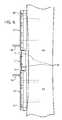
- FIG. 9shows the second embodiment of a bone plate system or bone bridge 100 in accordance with the invention surgically installed across a bone fracture 150 .
- the bone bridge 100is in a tensioned state following the plates 102 and 104 being spaced apart at a fixed distance to provide a controlled amount of compression, held in position during surgical installation and subsequently released to allow compressive force to be applied to a fracture.
- the bone screws 160 and 162are installed to anchor the movable plate 104 onto the bone fragment 152 .
- the bone screw 162 and 164are installed to anchor the fixed plate 102 onto the opposing bone fragment 154 .
- the microcable 130is engaged with and around the movable plate 104 while the tube 110 is engaged with and around the fixed plate 102 .
- the plates 102 and 104are spaced apart along the legs 112 and 114 with the microcable in tension pulling the plates toward each other and correspondingly furnishing the compressive force illustrated by arrows 170 on the fracture 150 .
- the graph of FIG. 10illustrates force vs. displacement and energy storage in the apparatus of the invention.
- the force as a function of displacementis substantially linear with a limited rate of change (slope) in a significant region of the graph.
- the inventionis pre-tensioned or biased at a point 80 on curve 81 , calculated to be in a substantially linear region of the curve 81 by the elastic microcable.
- the bias point 80is predetermined to allow room for contraction and/or expansion without either a) breaking the cable, or b) incurring excessively low or excessively high tension.
- the bias point of the cable in the inventiondeparts from prior bone plates, which have useful active ranges of only tenths of a millimeter due to the extremely high modulus of the solid metal parts as previously used.
- the graph of FIG. 10also illustrates energy storage in the apparatus of the invention, which is an alternate way of viewing or describing the action of the apparatus.
- the total area under the curve 81represents the energy stored in the apparatus of the invention (primarily in the elastomeric cable) with the tension set at the predetermined bias point.
- the apparatuscan contract to the limit 82 , performing work equal to the hatched area 86 (part of the total area under 81 ).
- the bias pointis set at a point such that the pre-loaded apparatus stores energy of at least 0.1 Joules. More preferably, the preloaded apparatus stores energy of at least 0.5 Joules, more specifically in the range 0.5 to 10 Joules. This energy storage is believed to provide significant advantage over the relatively low energy storage of prior cables.
- FIG. 10also shows that the elastic curve of the device has a corner, and rolls off rapidly at lower extensions (region 88 ) as, for example, the rails contact the elastomeric bumpers 28 and 29 in the first embodiment shown, limiting the range of contraction.
- the energy storage capacity of the inventionprovides advantage in at least two ways: the bone plate better accommodates contraction and expansion during healing, and the tension provides a dynamic load on the bone during healing, thereby preventing “stress shielding” and the resulting atrophy of bone which can occur with static metal bone plates.
- One of the slidable members 10 or 12could be integrated with the rail 14 , allowing the second member to slide for contraction.
- Variants of the railcould be used, including telescoping rails, multiple rails, tongue and groove slots, dovetailed slots and tongue, or other telescoping or contractible mechanisms.
- the U-shaped tube 110could have a different cross section such as being square or hexagonal.
- a single tube 110could be employed in a manner similar to a rail with the microcable running down the tube but connected at opposite ends to opposing plates.
- slidable members and/or railcould be contoured in cross section, and the contact points between the members and the bone could be varied. For example, minimal contact feet could be employed, or aggressive features such as teeth could be provided to grip the bone.
- minimal contact feetcould be employed, or aggressive features such as teeth could be provided to grip the bone.
Landscapes
- Health & Medical Sciences (AREA)
- Orthopedic Medicine & Surgery (AREA)
- Surgery (AREA)
- Life Sciences & Earth Sciences (AREA)
- Heart & Thoracic Surgery (AREA)
- Nuclear Medicine, Radiotherapy & Molecular Imaging (AREA)
- Engineering & Computer Science (AREA)
- Biomedical Technology (AREA)
- Neurology (AREA)
- Medical Informatics (AREA)
- Molecular Biology (AREA)
- Animal Behavior & Ethology (AREA)
- General Health & Medical Sciences (AREA)
- Public Health (AREA)
- Veterinary Medicine (AREA)
- Surgical Instruments (AREA)
- Materials For Medical Uses (AREA)
Abstract
Description
Claims (14)
Priority Applications (1)
| Application Number | Priority Date | Filing Date | Title |
|---|---|---|---|
| US11/561,095US8083781B2 (en) | 2006-06-16 | 2006-11-17 | Bone plate system providing dynamic compression |
Applications Claiming Priority (2)
| Application Number | Priority Date | Filing Date | Title |
|---|---|---|---|
| US11/454,344US8257404B2 (en) | 2006-06-16 | 2006-06-16 | Bone plate with dynamic compression |
| US11/561,095US8083781B2 (en) | 2006-06-16 | 2006-11-17 | Bone plate system providing dynamic compression |
Related Parent Applications (1)
| Application Number | Title | Priority Date | Filing Date |
|---|---|---|---|
| US11/454,344Continuation-In-PartUS8257404B2 (en) | 2006-06-16 | 2006-06-16 | Bone plate with dynamic compression |
Publications (2)
| Publication Number | Publication Date |
|---|---|
| US20070293864A1 US20070293864A1 (en) | 2007-12-20 |
| US8083781B2true US8083781B2 (en) | 2011-12-27 |
Family
ID=38834007
Family Applications (2)
| Application Number | Title | Priority Date | Filing Date |
|---|---|---|---|
| US11/454,344Active2027-07-18US8257404B2 (en) | 2006-06-16 | 2006-06-16 | Bone plate with dynamic compression |
| US11/561,095Active2029-03-24US8083781B2 (en) | 2006-06-16 | 2006-11-17 | Bone plate system providing dynamic compression |
Family Applications Before (1)
| Application Number | Title | Priority Date | Filing Date |
|---|---|---|---|
| US11/454,344Active2027-07-18US8257404B2 (en) | 2006-06-16 | 2006-06-16 | Bone plate with dynamic compression |
Country Status (2)
| Country | Link |
|---|---|
| US (2) | US8257404B2 (en) |
| WO (1) | WO2007149325A2 (en) |
Cited By (10)
| Publication number | Priority date | Publication date | Assignee | Title |
|---|---|---|---|---|
| USD717433S1 (en)* | 2013-07-07 | 2014-11-11 | Seyed Salman Samani | Orthopedic dual sliding compression plate |
| USD734853S1 (en) | 2009-10-14 | 2015-07-21 | Nuvasive, Inc. | Bone plate |
| US20150238238A1 (en)* | 2014-02-27 | 2015-08-27 | Biomedical Enterprises, Inc. | Method and apparatus for use of a compressing plate |
| US20150289910A1 (en)* | 2014-04-12 | 2015-10-15 | Seyed Alireza Mirghasemi | Modular bone plate |
| US9615866B1 (en) | 2004-10-18 | 2017-04-11 | Nuvasive, Inc. | Surgical fixation system and related methods |
| US9883897B2 (en) | 2014-09-25 | 2018-02-06 | Biomedical Enterprises, Inc. | Method and apparatus for a compressing plate |
| US11123117B1 (en) | 2011-11-01 | 2021-09-21 | Nuvasive, Inc. | Surgical fixation system and related methods |
| US11241263B1 (en) | 2018-03-06 | 2022-02-08 | William E. Nordt, III | Bone plate apparatus with articulating joints |
| US12023075B2 (en) | 2022-03-21 | 2024-07-02 | Ryan J. Niver | Bone fixation systems and methods for fixating bones |
| US12127773B2 (en) | 2022-06-15 | 2024-10-29 | DePuy Synthes Products, Inc. | Orthopedic fixation system and methods of use thereof |
Families Citing this family (36)
| Publication number | Priority date | Publication date | Assignee | Title |
|---|---|---|---|---|
| US8262656B2 (en)* | 2004-09-03 | 2012-09-11 | A.M. Surgical, Inc. | External fixation device for fractures |
| US7699874B2 (en)* | 2006-03-01 | 2010-04-20 | Warsaw Orthopedic, Inc. | Low profile spinal rod connector system |
| US7641675B2 (en)* | 2006-03-08 | 2010-01-05 | Warsaw Orthopedic, Inc. | Flexible bone plates and methods for dynamic spinal stabilization |
| US7842037B2 (en)* | 2006-09-27 | 2010-11-30 | Dupuy Products, Inc. | Flexible bone fixation device |
| US8262710B2 (en) | 2006-10-24 | 2012-09-11 | Aesculap Implant Systems, Llc | Dynamic stabilization device for anterior lower lumbar vertebral fusion |
| US20080147124A1 (en)* | 2006-10-31 | 2008-06-19 | Haidukewych George J | Bone plate system with slidable compression holes |
| US8206390B2 (en)* | 2006-11-02 | 2012-06-26 | Warsaw Orthopedic, Inc. | Uni-directional ratcheting bone plate assembly |
| US20090043341A1 (en)* | 2007-08-09 | 2009-02-12 | Aesculap, Inc. | Dynamic extension plate for anterior cervical fusion and method of installation |
| US8414599B1 (en) | 2007-12-31 | 2013-04-09 | Dallen Medical, Inc. | Dynamic suture tensioning device and methods |
| US8613755B1 (en) | 2008-03-18 | 2013-12-24 | Dallen Medical, Inc. | Knotless dynamic suture tensioning device and methods |
| US8177811B2 (en)* | 2008-07-25 | 2012-05-15 | Clariance | Joint prosthesis for total lumbar arthroplasty by posterior approach |
| WO2010017649A1 (en)* | 2008-08-15 | 2010-02-18 | Ao Technology Ag | Bone fixation device |
| WO2010025405A1 (en)* | 2008-08-29 | 2010-03-04 | Life Spine, Inc. | Single-sided dynamic spine plates |
| US8579901B1 (en) | 2009-06-17 | 2013-11-12 | Dallen Medical, Inc. | Suture band buckle and methods |
| US8808333B2 (en) | 2009-07-06 | 2014-08-19 | Zimmer Gmbh | Periprosthetic bone plates |
| US8715297B1 (en) | 2009-07-14 | 2014-05-06 | Dallen Medical, Inc. | Flat suture banding system and methods |
| US8668696B2 (en) | 2009-08-20 | 2014-03-11 | Dallen Medical, Inc. | Low friction buckle tightening systems and methods |
| US8974456B2 (en) | 2011-05-19 | 2015-03-10 | Dallen Medical, Inc. | Hybrid medical device implant with migration management |
| US9414927B2 (en) | 2011-12-08 | 2016-08-16 | Imds Llc | Shoulder arthroplasty |
| US9439768B2 (en) | 2011-12-08 | 2016-09-13 | Imds Llc | Glenoid vault fixation |
| US9414873B2 (en) | 2012-01-05 | 2016-08-16 | The Cleveland Clinic Foundation | Modular bone fixation system |
| US9788957B2 (en) | 2012-12-07 | 2017-10-17 | Cleveland Clinic Foundation | Glenoid vault fixation |
| US9999454B2 (en) | 2013-12-05 | 2018-06-19 | A&E Advanced Closure Systems, Llc | Bone plate system and method |
| EP2990756B1 (en)* | 2013-12-27 | 2019-08-21 | Cmiws Co., Ltd. | Strain sensor and strain sensor installation method |
| USD749740S1 (en)* | 2014-11-17 | 2016-02-16 | Biomet C.V. | Fusion bone plate |
| US10123831B2 (en) | 2015-03-03 | 2018-11-13 | Pioneer Surgical Technology, Inc. | Bone compression device and method |
| US9615931B2 (en)* | 2015-03-20 | 2017-04-11 | Globus Medical, Inc. | Surgical plate systems |
| US10130358B2 (en) | 2015-10-07 | 2018-11-20 | Arthrex, Inc. | Devices for controlling the unloading of superelastic and shape memory orthopedic implants |
| IT201700006369A1 (en)* | 2017-01-20 | 2018-07-20 | Orthofix Srl | Internal plate fixation device |
| CN112367937A (en) | 2018-06-29 | 2021-02-12 | 先锋外科技术公司 | Bone plating system |
| CN109259837B (en)* | 2018-08-09 | 2021-01-01 | 盐城日升月恒智能科技有限公司 | Rope wheel bone extension fixture |
| CN112826579A (en)* | 2019-12-02 | 2021-05-25 | 青岛大学附属医院 | Static-dynamic conversion type herringbone crest locking dynamic compression plate system |
| CN113317857A (en)* | 2020-02-28 | 2021-08-31 | 西安市中心医院 | Assembled adjustable clavicle fixing device with resetting function and use method thereof |
| US11877779B2 (en) | 2020-03-26 | 2024-01-23 | Xtant Medical Holdings, Inc. | Bone plate system |
| US20240099748A1 (en) | 2020-12-17 | 2024-03-28 | Dgt Medical Limited | A bone fixation device and system and method for using the device |
| US11883080B1 (en)* | 2022-07-13 | 2024-01-30 | Globus Medical, Inc | Reverse dynamization implants |
Citations (9)
| Publication number | Priority date | Publication date | Assignee | Title |
|---|---|---|---|---|
| US5458642A (en)* | 1994-01-18 | 1995-10-17 | Beer; John C. | Synthetic intervertebral disc |
| US5797912A (en)* | 1995-09-22 | 1998-08-25 | Terray Corporation | Washer for use with a bone screw |
| US6682530B2 (en)* | 2002-01-14 | 2004-01-27 | Robert A Dixon | Dynamized vertebral stabilizer using an outrigger implant |
| US20050043732A1 (en)* | 2003-08-18 | 2005-02-24 | Dalton Brian E. | Cervical compression plate assembly |
| US20050192581A1 (en)* | 2004-02-27 | 2005-09-01 | Molz Fred J. | Radiopaque, coaxial orthopedic tether design and method |
| US20050203519A1 (en)* | 2004-03-09 | 2005-09-15 | Jurgen Harms | Rod-like element for application in spinal or trauma surgery, and stabilization device with such a rod-like element |
| US20060235405A1 (en)* | 2005-03-31 | 2006-10-19 | Hawkes David T | Active compression orthopedic plate system and method for using the same |
| US20060264941A1 (en)* | 2005-05-06 | 2006-11-23 | Sumner Technologies, Llc | Pedicle screw-based dynamic posterior stabilization systems and methods |
| US20060264937A1 (en)* | 2005-05-04 | 2006-11-23 | White Patrick M | Mobile spine stabilization device |
Family Cites Families (10)
| Publication number | Priority date | Publication date | Assignee | Title |
|---|---|---|---|---|
| US2387131A (en)* | 1943-04-08 | 1945-10-16 | Fernandez Pedro Eduardo Gomez | Indirect seam or suture for wounds |
| US3244170A (en)* | 1962-11-23 | 1966-04-05 | Robert T Mcelvenny | Compression type bone splint |
| US6120505A (en)* | 1995-06-01 | 2000-09-19 | Acumed, Inc. | Wire clamp assembly |
| US5415661A (en)* | 1993-03-24 | 1995-05-16 | University Of Miami | Implantable spinal assist device |
| US5607430A (en)* | 1995-08-25 | 1997-03-04 | Biomet, Inc. | Bone stabilization implant having a bone plate portion with integral cable clamping means |
| EP0999795A1 (en)* | 1997-07-31 | 2000-05-17 | Plus Endoprothetik Ag | Device for stiffening and/or correcting a vertebral column or such like |
| US6645211B2 (en)* | 2001-02-07 | 2003-11-11 | Howmedica Osteonics Corp. | Orthopedic support system and method of installation |
| US6755833B1 (en)* | 2001-12-14 | 2004-06-29 | Kamaljit S. Paul | Bone support assembly |
| US7811312B2 (en)* | 2002-12-04 | 2010-10-12 | Morphographics, Lc | Bone alignment implant and method of use |
| US20060264935A1 (en)* | 2005-05-04 | 2006-11-23 | White Patrick M | Orthopedic stabilization device |
- 2006
- 2006-06-16USUS11/454,344patent/US8257404B2/enactiveActive
- 2006-11-17USUS11/561,095patent/US8083781B2/enactiveActive
- 2007
- 2007-06-15WOPCT/US2007/014069patent/WO2007149325A2/enactiveApplication Filing
Patent Citations (9)
| Publication number | Priority date | Publication date | Assignee | Title |
|---|---|---|---|---|
| US5458642A (en)* | 1994-01-18 | 1995-10-17 | Beer; John C. | Synthetic intervertebral disc |
| US5797912A (en)* | 1995-09-22 | 1998-08-25 | Terray Corporation | Washer for use with a bone screw |
| US6682530B2 (en)* | 2002-01-14 | 2004-01-27 | Robert A Dixon | Dynamized vertebral stabilizer using an outrigger implant |
| US20050043732A1 (en)* | 2003-08-18 | 2005-02-24 | Dalton Brian E. | Cervical compression plate assembly |
| US20050192581A1 (en)* | 2004-02-27 | 2005-09-01 | Molz Fred J. | Radiopaque, coaxial orthopedic tether design and method |
| US20050203519A1 (en)* | 2004-03-09 | 2005-09-15 | Jurgen Harms | Rod-like element for application in spinal or trauma surgery, and stabilization device with such a rod-like element |
| US20060235405A1 (en)* | 2005-03-31 | 2006-10-19 | Hawkes David T | Active compression orthopedic plate system and method for using the same |
| US20060264937A1 (en)* | 2005-05-04 | 2006-11-23 | White Patrick M | Mobile spine stabilization device |
| US20060264941A1 (en)* | 2005-05-06 | 2006-11-23 | Sumner Technologies, Llc | Pedicle screw-based dynamic posterior stabilization systems and methods |
Non-Patent Citations (2)
| Title |
|---|
| Sarin et al. (A Novel Iso-Elastic Cerclage Cable for Treatment of Fractures). Kinamed, Inc. Poster presented at 2005 Orthopedic Research Society (held Feb. 20-23, 2005).* |
| Sarin et al. (Novel Iso-Elastic Cerclage Cable for Fracture Treatment). Kinamed Inc. Dated Sep. 23-25, 2004, Rome, Italy. Journal of Bone and Joint Surgery-British Volume. vol. 90-B. Issue SUPP-I, 189. International Society for Technology in Arthroplasy.* |
Cited By (13)
| Publication number | Priority date | Publication date | Assignee | Title |
|---|---|---|---|---|
| US9615866B1 (en) | 2004-10-18 | 2017-04-11 | Nuvasive, Inc. | Surgical fixation system and related methods |
| USD754857S1 (en) | 2009-10-14 | 2016-04-26 | Nuvasive, Inc. | Bone plate |
| USD734853S1 (en) | 2009-10-14 | 2015-07-21 | Nuvasive, Inc. | Bone plate |
| US11123117B1 (en) | 2011-11-01 | 2021-09-21 | Nuvasive, Inc. | Surgical fixation system and related methods |
| USD717433S1 (en)* | 2013-07-07 | 2014-11-11 | Seyed Salman Samani | Orthopedic dual sliding compression plate |
| US9408647B2 (en)* | 2014-02-27 | 2016-08-09 | Biomedical Enterprises, Inc. | Method and apparatus for use of a compressing plate |
| US20150238238A1 (en)* | 2014-02-27 | 2015-08-27 | Biomedical Enterprises, Inc. | Method and apparatus for use of a compressing plate |
| US20150289910A1 (en)* | 2014-04-12 | 2015-10-15 | Seyed Alireza Mirghasemi | Modular bone plate |
| US9962204B2 (en)* | 2014-04-12 | 2018-05-08 | Seyed Alireza Mirghasemi | Modular bone plate |
| US9883897B2 (en) | 2014-09-25 | 2018-02-06 | Biomedical Enterprises, Inc. | Method and apparatus for a compressing plate |
| US11241263B1 (en) | 2018-03-06 | 2022-02-08 | William E. Nordt, III | Bone plate apparatus with articulating joints |
| US12023075B2 (en) | 2022-03-21 | 2024-07-02 | Ryan J. Niver | Bone fixation systems and methods for fixating bones |
| US12127773B2 (en) | 2022-06-15 | 2024-10-29 | DePuy Synthes Products, Inc. | Orthopedic fixation system and methods of use thereof |
Also Published As
| Publication number | Publication date |
|---|---|
| US20070293864A1 (en) | 2007-12-20 |
| WO2007149325A2 (en) | 2007-12-27 |
| US8257404B2 (en) | 2012-09-04 |
| WO2007149325A3 (en) | 2008-06-05 |
| US20080015589A1 (en) | 2008-01-17 |
Similar Documents
| Publication | Publication Date | Title |
|---|---|---|
| US8083781B2 (en) | Bone plate system providing dynamic compression | |
| US8226693B2 (en) | Bone bridge providing dynamic compression on bone fractures | |
| US7942876B2 (en) | Intra-medullary implant with active compression | |
| US11213322B2 (en) | Dynamic spinal stabilization with rod-cord longitudinal connecting members | |
| US4655203A (en) | Bone fracture surgical device | |
| US6589246B1 (en) | Method of applying an active compressive force continuously across a fracture | |
| CN102421381B (en) | Bone fixation component with self-retaining strap | |
| US8506599B2 (en) | Dynamic stabilization assembly with frusto-conical connection | |
| CA2734065C (en) | Bone fixation device | |
| US7625395B2 (en) | Implantable screw for stabilization of a joint or a bone fracture | |
| US10722344B2 (en) | Adjustable fixation device | |
| AU2015320378B2 (en) | Implant devices and systems for stabilized fixation of bone and soft tissue | |
| US20130304133A1 (en) | Cable anchor systems and methods | |
| JP2023541866A (en) | Headless compression screw with attachment mechanism | |
| US9345469B2 (en) | Vector compression system | |
| US20220233221A1 (en) | Balanced axial compression assembly for bone | |
| CN217310717U (en) | Degradable fixed sheath and cruciate ligament reconstruction system thereof | |
| US12161318B2 (en) | Re-tensionable suture anchor system and related methods | |
| Gautier | Bridge plating | |
| GB2427141A (en) | A bone fixator allowing predetermined relative movement between the ends of a fractured bone |
Legal Events
| Date | Code | Title | Description |
|---|---|---|---|
| AS | Assignment | Owner name:POLY 5 GROUP LLC, CALIFORNIA Free format text:ASSIGNMENT OF ASSIGNORS INTEREST;ASSIGNORS:REIMELS, WILLIAM J;HACK, BRADFORD H;REEL/FRAME:022729/0274 Effective date:20070622 | |
| AS | Assignment | Owner name:KINAMED INCORPORATED, CALIFORNIA Free format text:SECURITY AGREEMENT;ASSIGNOR:POLY-5 GROUP, LLC;REEL/FRAME:023085/0985 Effective date:20090716 | |
| AS | Assignment | Owner name:ACCELERATED ORTHOPEDIC REPAIR, LLC, NEVADA Free format text:ASSIGNMENT OF ASSIGNORS INTEREST;ASSIGNOR:POLY-5 GROUP, LLC;REEL/FRAME:025323/0055 Effective date:20091208 | |
| FEPP | Fee payment procedure | Free format text:PAYOR NUMBER ASSIGNED (ORIGINAL EVENT CODE: ASPN); ENTITY STATUS OF PATENT OWNER: SMALL ENTITY | |
| STCF | Information on status: patent grant | Free format text:PATENTED CASE | |
| FPAY | Fee payment | Year of fee payment:4 | |
| AS | Assignment | Owner name:KINAMED, INC., CALIFORNIA Free format text:ASSIGNMENT OF ASSIGNORS INTEREST;ASSIGNOR:ACCELERATED ORTHOPEDIC REPAIR, LLC;REEL/FRAME:039615/0014 Effective date:20160708 | |
| MAFP | Maintenance fee payment | Free format text:PAYMENT OF MAINTENANCE FEE, 8TH YR, SMALL ENTITY (ORIGINAL EVENT CODE: M2552); ENTITY STATUS OF PATENT OWNER: SMALL ENTITY Year of fee payment:8 | |
| MAFP | Maintenance fee payment | Free format text:PAYMENT OF MAINTENANCE FEE, 12TH YR, SMALL ENTITY (ORIGINAL EVENT CODE: M2553); ENTITY STATUS OF PATENT OWNER: SMALL ENTITY Year of fee payment:12 |