US8083743B2 - Craniospinal fusion method and apparatus - Google Patents
Craniospinal fusion method and apparatusDownload PDFInfo
- Publication number
- US8083743B2 US8083743B2US11/832,646US83264607AUS8083743B2US 8083743 B2US8083743 B2US 8083743B2US 83264607 AUS83264607 AUS 83264607AUS 8083743 B2US8083743 B2US 8083743B2
- Authority
- US
- United States
- Prior art keywords
- cranium
- plate member
- plate
- human
- accommodation space
- Prior art date
- Legal status (The legal status is an assumption and is not a legal conclusion. Google has not performed a legal analysis and makes no representation as to the accuracy of the status listed.)
- Active, expires
Links
- 238000007500overflow downdraw methodMethods0.000title1
- 210000000988bone and boneAnatomy0.000claimsabstractdescription116
- 239000000463materialSubstances0.000claimsabstractdescription81
- 230000004927fusionEffects0.000claimsabstractdescription59
- 230000004308accommodationEffects0.000claimsabstractdescription46
- 239000011248coating agentSubstances0.000claimsdescription5
- 238000000576coating methodMethods0.000claimsdescription5
- 229910052751metalInorganic materials0.000claimsdescription5
- 239000002184metalSubstances0.000claimsdescription5
- 230000034127bone morphogenesisEffects0.000claims2
- 238000000034methodMethods0.000abstractdescription13
- 230000006641stabilisationEffects0.000abstractdescription11
- 238000011105stabilizationMethods0.000abstractdescription11
- 230000009467reductionEffects0.000abstractdescription10
- 230000002159abnormal effectEffects0.000abstractdescription7
- 210000000133brain stemAnatomy0.000abstractdescription7
- 210000000278spinal cordAnatomy0.000abstractdescription4
- 210000003625skullAnatomy0.000description10
- 239000000126substanceSubstances0.000description8
- 230000006835compressionEffects0.000description6
- 238000007906compressionMethods0.000description6
- 238000001356surgical procedureMethods0.000description6
- 208000032170Congenital AbnormalitiesDiseases0.000description5
- 230000002980postoperative effectEffects0.000description5
- 206010057115PlatybasiaDiseases0.000description4
- 210000001142backAnatomy0.000description4
- 239000000316bone substituteSubstances0.000description4
- 208000037265diseases, disorders, signs and symptomsDiseases0.000description4
- 208000035475disorderDiseases0.000description4
- 230000006870functionEffects0.000description4
- 230000007246mechanismEffects0.000description4
- GUVRBAGPIYLISA-UHFFFAOYSA-Ntantalum atomChemical compound[Ta]GUVRBAGPIYLISA-UHFFFAOYSA-N0.000description4
- 210000004204blood vesselAnatomy0.000description3
- 230000008468bone growthEffects0.000description3
- 239000002131composite materialSubstances0.000description3
- 238000005516engineering processMethods0.000description3
- 230000012010growthEffects0.000description3
- 230000033001locomotionEffects0.000description3
- 206010039073rheumatoid arthritisDiseases0.000description3
- 230000000087stabilizing effectEffects0.000description3
- 210000001519tissueAnatomy0.000description3
- 238000013519translationMethods0.000description3
- 208000006096Attention Deficit Disorder with HyperactivityDiseases0.000description2
- 208000036864Attention deficit/hyperactivity diseaseDiseases0.000description2
- 206010023204Joint dislocationDiseases0.000description2
- 206010028980NeoplasmDiseases0.000description2
- 230000006978adaptationEffects0.000description2
- 208000015802attention deficit-hyperactivity diseaseDiseases0.000description2
- 230000001684chronic effectEffects0.000description2
- 150000001875compoundsChemical class0.000description2
- 230000001054cortical effectEffects0.000description2
- 230000003412degenerative effectEffects0.000description2
- 229910052588hydroxylapatiteInorganic materials0.000description2
- 230000007774longtermEffects0.000description2
- XYJRXVWERLGGKC-UHFFFAOYSA-Dpentacalcium;hydroxide;triphosphateChemical compound[OH-].[Ca+2].[Ca+2].[Ca+2].[Ca+2].[Ca+2].[O-]P([O-])([O-])=O.[O-]P([O-])([O-])=O.[O-]P([O-])([O-])=OXYJRXVWERLGGKC-UHFFFAOYSA-D0.000description2
- 230000008569processEffects0.000description2
- 239000007787solidSubstances0.000description2
- 208000011580syndromic diseaseDiseases0.000description2
- 210000000115thoracic cavityAnatomy0.000description2
- 208000036640Asperger diseaseDiseases0.000description1
- 201000006062Asperger syndromeDiseases0.000description1
- 206010003805AutismDiseases0.000description1
- 208000020706Autistic diseaseDiseases0.000description1
- 102000008186CollagenHuman genes0.000description1
- 108010035532CollagenProteins0.000description1
- 208000027205Congenital diseaseDiseases0.000description1
- 206010017076FractureDiseases0.000description1
- 206010019196Head injuryDiseases0.000description1
- 206010019233HeadachesDiseases0.000description1
- 206010023509KyphosisDiseases0.000description1
- 241001465754MetazoaSpecies0.000description1
- 206010028570MyelopathyDiseases0.000description1
- 206010028836Neck painDiseases0.000description1
- 208000004286OsteochondrodysplasiasDiseases0.000description1
- 206010031243Osteogenesis imperfectaDiseases0.000description1
- 206010040030Sensory lossDiseases0.000description1
- 229910001069Ti alloyInorganic materials0.000description1
- RTAQQCXQSZGOHL-UHFFFAOYSA-NTitaniumChemical compound[Ti]RTAQQCXQSZGOHL-UHFFFAOYSA-N0.000description1
- 206010049514Traumatic fractureDiseases0.000description1
- 208000027418Wounds and injuryDiseases0.000description1
- 230000019552anatomical structure morphogenesisEffects0.000description1
- 230000000712assemblyEffects0.000description1
- 238000000429assemblyMethods0.000description1
- 238000005452bendingMethods0.000description1
- 239000000560biocompatible materialSubstances0.000description1
- 230000015572biosynthetic processEffects0.000description1
- 210000002805bone matrixAnatomy0.000description1
- 201000011510cancerDiseases0.000description1
- 239000000919ceramicSubstances0.000description1
- 229920001436collagenPolymers0.000description1
- 230000000295complement effectEffects0.000description1
- 239000004020conductorSubstances0.000description1
- 238000010276constructionMethods0.000description1
- 230000006378damageEffects0.000description1
- 230000000991decompressive effectEffects0.000description1
- 230000003247decreasing effectEffects0.000description1
- 230000003111delayed effectEffects0.000description1
- 230000008021depositionEffects0.000description1
- 238000013461designMethods0.000description1
- 230000006866deteriorationEffects0.000description1
- 238000005553drillingMethods0.000description1
- 206010013932dyslexiaDiseases0.000description1
- 230000000694effectsEffects0.000description1
- 230000002708enhancing effectEffects0.000description1
- 238000002594fluoroscopyMethods0.000description1
- 208000021302gastroesophageal reflux diseaseDiseases0.000description1
- 125000001475halogen functional groupChemical group0.000description1
- 231100000869headacheToxicity0.000description1
- 208000035231inattentive type attention deficit hyperactivity diseaseDiseases0.000description1
- 238000010348incorporationMethods0.000description1
- 208000015181infectious diseaseDiseases0.000description1
- 208000014674injuryDiseases0.000description1
- 238000003780insertionMethods0.000description1
- 230000037431insertionEffects0.000description1
- 238000007689inspectionMethods0.000description1
- 230000005226mechanical processes and functionsEffects0.000description1
- 229910001092metal group alloyInorganic materials0.000description1
- 239000007769metal materialSubstances0.000description1
- 230000005012migrationEffects0.000description1
- 238000013508migrationMethods0.000description1
- 239000000203mixtureSubstances0.000description1
- 210000003205muscleAnatomy0.000description1
- 230000007971neurological deficitEffects0.000description1
- 230000000926neurological effectEffects0.000description1
- 230000007658neurological functionEffects0.000description1
- 235000003715nutritional statusNutrition0.000description1
- 230000011164ossificationEffects0.000description1
- 230000007170pathologyEffects0.000description1
- 230000035790physiological processes and functionsEffects0.000description1
- 239000011148porous materialSubstances0.000description1
- 230000007425progressive declineEffects0.000description1
- 230000001737promoting effectEffects0.000description1
- 238000011084recoveryMethods0.000description1
- 238000002271resectionMethods0.000description1
- 201000002859sleep apneaDiseases0.000description1
- 241000894007speciesSpecies0.000description1
- 206010062920spondyloepiphyseal dysplasiaDiseases0.000description1
- 201000002962spondyloepiphyseal dysplasia with congenital joint dislocationsDiseases0.000description1
- 150000003431steroidsChemical class0.000description1
- 239000000758substrateSubstances0.000description1
- 238000011477surgical interventionMethods0.000description1
- 208000024891symptomDiseases0.000description1
- 229910052715tantalumInorganic materials0.000description1
- 239000010936titaniumSubstances0.000description1
- 229910052719titaniumInorganic materials0.000description1
- 230000008733traumaEffects0.000description1
- 210000001186vagus nerveAnatomy0.000description1
- 230000007998vessel formationEffects0.000description1
- 210000002517zygapophyseal jointAnatomy0.000description1
Images


Classifications
- A—HUMAN NECESSITIES
- A61—MEDICAL OR VETERINARY SCIENCE; HYGIENE
- A61B—DIAGNOSIS; SURGERY; IDENTIFICATION
- A61B17/00—Surgical instruments, devices or methods
- A61B17/56—Surgical instruments or methods for treatment of bones or joints; Devices specially adapted therefor
- A61B17/58—Surgical instruments or methods for treatment of bones or joints; Devices specially adapted therefor for osteosynthesis, e.g. bone plates, screws or setting implements
- A61B17/68—Internal fixation devices, including fasteners and spinal fixators, even if a part thereof projects from the skin
- A61B17/80—Cortical plates, i.e. bone plates; Instruments for holding or positioning cortical plates, or for compressing bones attached to cortical plates
- A61B17/8061—Cortical plates, i.e. bone plates; Instruments for holding or positioning cortical plates, or for compressing bones attached to cortical plates specially adapted for particular bones
- A61B17/8071—Cortical plates, i.e. bone plates; Instruments for holding or positioning cortical plates, or for compressing bones attached to cortical plates specially adapted for particular bones for the jaw
- A—HUMAN NECESSITIES
- A61—MEDICAL OR VETERINARY SCIENCE; HYGIENE
- A61B—DIAGNOSIS; SURGERY; IDENTIFICATION
- A61B17/00—Surgical instruments, devices or methods
- A61B17/56—Surgical instruments or methods for treatment of bones or joints; Devices specially adapted therefor
- A61B17/58—Surgical instruments or methods for treatment of bones or joints; Devices specially adapted therefor for osteosynthesis, e.g. bone plates, screws or setting implements
- A61B17/68—Internal fixation devices, including fasteners and spinal fixators, even if a part thereof projects from the skin
- A61B17/70—Spinal positioners or stabilisers, e.g. stabilisers comprising fluid filler in an implant
- A61B17/7055—Spinal positioners or stabilisers, e.g. stabilisers comprising fluid filler in an implant connected to sacrum, pelvis or skull
- A—HUMAN NECESSITIES
- A61—MEDICAL OR VETERINARY SCIENCE; HYGIENE
- A61B—DIAGNOSIS; SURGERY; IDENTIFICATION
- A61B17/00—Surgical instruments, devices or methods
- A61B17/56—Surgical instruments or methods for treatment of bones or joints; Devices specially adapted therefor
- A61B17/58—Surgical instruments or methods for treatment of bones or joints; Devices specially adapted therefor for osteosynthesis, e.g. bone plates, screws or setting implements
- A61B17/68—Internal fixation devices, including fasteners and spinal fixators, even if a part thereof projects from the skin
- A61B17/80—Cortical plates, i.e. bone plates; Instruments for holding or positioning cortical plates, or for compressing bones attached to cortical plates
- A—HUMAN NECESSITIES
- A61—MEDICAL OR VETERINARY SCIENCE; HYGIENE
- A61B—DIAGNOSIS; SURGERY; IDENTIFICATION
- A61B17/00—Surgical instruments, devices or methods
- A61B17/56—Surgical instruments or methods for treatment of bones or joints; Devices specially adapted therefor
- A61B17/58—Surgical instruments or methods for treatment of bones or joints; Devices specially adapted therefor for osteosynthesis, e.g. bone plates, screws or setting implements
- A61B17/88—Osteosynthesis instruments; Methods or means for implanting or extracting internal or external fixation devices
- A61B17/8875—Screwdrivers, spanners or wrenches
- A61B17/8886—Screwdrivers, spanners or wrenches holding the screw head
- A61B17/8891—Screwdrivers, spanners or wrenches holding the screw head at its periphery
- A—HUMAN NECESSITIES
- A61—MEDICAL OR VETERINARY SCIENCE; HYGIENE
- A61B—DIAGNOSIS; SURGERY; IDENTIFICATION
- A61B17/00—Surgical instruments, devices or methods
- A61B17/56—Surgical instruments or methods for treatment of bones or joints; Devices specially adapted therefor
- A61B17/58—Surgical instruments or methods for treatment of bones or joints; Devices specially adapted therefor for osteosynthesis, e.g. bone plates, screws or setting implements
- A61B17/68—Internal fixation devices, including fasteners and spinal fixators, even if a part thereof projects from the skin
- A61B17/80—Cortical plates, i.e. bone plates; Instruments for holding or positioning cortical plates, or for compressing bones attached to cortical plates
- A61B17/8085—Cortical plates, i.e. bone plates; Instruments for holding or positioning cortical plates, or for compressing bones attached to cortical plates with pliable or malleable elements or having a mesh-like structure, e.g. small strips
- A—HUMAN NECESSITIES
- A61—MEDICAL OR VETERINARY SCIENCE; HYGIENE
- A61B—DIAGNOSIS; SURGERY; IDENTIFICATION
- A61B17/00—Surgical instruments, devices or methods
- A61B2017/00004—(bio)absorbable, (bio)resorbable or resorptive
- Y—GENERAL TAGGING OF NEW TECHNOLOGICAL DEVELOPMENTS; GENERAL TAGGING OF CROSS-SECTIONAL TECHNOLOGIES SPANNING OVER SEVERAL SECTIONS OF THE IPC; TECHNICAL SUBJECTS COVERED BY FORMER USPC CROSS-REFERENCE ART COLLECTIONS [XRACs] AND DIGESTS
- Y10—TECHNICAL SUBJECTS COVERED BY FORMER USPC
- Y10S—TECHNICAL SUBJECTS COVERED BY FORMER USPC CROSS-REFERENCE ART COLLECTIONS [XRACs] AND DIGESTS
- Y10S606/00—Surgery
- Y10S606/902—Cortical plate specifically adapted for a particular bone
- Y10S606/903—Cranial and facial plate
Definitions
- the present inventionrelates to a method and apparatus for fixation, stabilization and fusion of the human occipitocervical junction.
- the normal range of motion of the craniospinal junctionincludes 27° of flexion and extension, and 90° of lateral rotation; the craniospinal junction is thus the most mobile and articulatable part of the human body. It is also the most active part of the human body in movement throughout the day, typically performing greater than 3 million motions a year.
- the craniospinal junctiontransmits the entire nervous structure to the body (with the exception of the vagus nerve), and is thus unfortunately susceptible to a host of degenerative disorders.
- Emblematic of theseis rheumatoid arthritis, a chronic degenerative condition that arises in 2% of the population, causing predictable changes in the joints and bone structure of the cervical spine, often including vertical migration of the odontoid and trauma to the ligamentous structures of the craniocervical junction.
- rheumatoid arthritissufferers develop atlantoaxial subluxation and 9% develop basilar invagination. Clinically these patients invariably experience severe neck pain and neurological deficits, including weakness and sensory loss. Untreated, patients suffer progressive decline, losing the ability to walk. The untreated patient with myelopathy due to compression of the spinal cord has a 50% likelihood of dying within 1 year. Surgical intervention is therefore necessary to stabilize the craniocervical junction, restore neurologic function and prevent further neurologic deterioration.
- occipitocervical stabilization in rheumatoid arthritiscan be especially challenging because of such factors as poor bone quality, poor nutritional status and long term steroid use.
- cranio-cervical instabilitycan include approximately 3,000 fractures of the upper spine related to head trauma each year; congenital diseases, including Down's, Morquio's and spondyloepiphyseal dysplasia syndromes, with a prevalence of at least 50,000; osteogenesis imperfecta, with a prevalence of 7,000 patients; cancer, with about 1000 cases per year; and numerous causes of bone softening. Tumors and infections may also cause destruction of the stabilizing elements.
- the largest group of patients suffering from poor craniocervical stabilizationlies in the pediatric group amongst a large group of children who have been misdiagnosed with neuropsychiatric disorders, such as Asperger's Syndrome, autism, Attention Deficit Hyperactivity Disorder and forms of dyslexia who harbor underlying disorders of the brainstem and spinal cord which result from subtle and sometimes gross anomalies which result in mechanical deformation and abnormal stresses of the neuraxis at the craniocervical junction.
- Various disordershave been found to frequently result in chronic and subtle neurological changes: retroflexion of the odontoid, platybasia, non-traditional forms of basilar invagination and an abnormal clivo-axial angle, which can result in deformity of the brainstem and upper spinal cord.
- the clivioaxial angleis depicted in FIG. 1
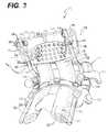
- an example of basilar invaginationis depicted in the image that is shown in FIG. 2
- compression to the brainstemis clearly visible.
- These conditionshave been reported to cause such symptoms as sleep apnea, delayed speech, gastroesophageal reflux, and altered behavior such as attention deficit disorder, headaches, and a myriad of other sensori-motor syndromes.
- the ubiquity of craniospinal junction pathologyhas only recently been appreciated.
- fixation deviceshave been described such as those that are disclosed in U.S. Pat. Nos. 5,030,220; 5,034,011; 5,545,164; 5,507,745; 6,547,790; 6,524,315; 6,902,565 B2 and U.S. Published Patent Applications US2005/0288669 A1; US2005/0283153 A1 and US2005/0080417 A1, all of which are hereby incorporated by reference as if set forth fully herein.
- a method for effecting fusion of the human occipitocervical junctionincludes steps of effecting fusion of a first portion of a bone forming material based structural member to a human cranium; and effecting fusion of a second portion of the bone forming material based structural member to a least one portion of a human cervical spine, whereby a fusion of the human occipitocervical junction is achieved.
- An article for use in the surgical fusion of the human occipitocervical junctionincludes a plate member having an outer edge, an outer surface and an inner surface that is constructed and arranged to be secured to a human cranium, the plate member being configured so as to define a graft accommodation space between the inner surface of the plate member and the cranium when the plate member has been secured to the cranium, the graft accommodation space being defined in part by a portion of the outer edge that is elevated with respect to a portion of the inner surface that is contacting the cranium so that the graft accommodation space is open to a space outside of the graft accommodation space, whereby a bone material based structural member may be positioned within the graft accommodation space so as to be fused to the cranium and to extend away from the plate member.
- a system for effecting fusion of the human occipitocervical junctionincludes a first bone material based structural member that is positioned so as to facilitate fusion of a first portion thereof to a human cranium and a second portion thereof to a cervical vertebral body; a second bone material based structural member that is positioned so as to facilitate fusion of a first portion thereof to a human cranium and a second portion thereof to a cervical vertebral body; and a transverse connector that is positioned to compress the first bone material based structural member and the second bone material based structural member against a vertebral body.
- a system for effecting fusion of the human occipitocervical junctionincludes surgically implantable instrumentation including a first support rod; a second support rod; cranium attachment means for attaching respective first portions of the first and second support rods to a human cranium; vertebral attachment means for attaching respective second portions of the first and second support rods to a human cervical vertebral body; and wherein the first and second support rods are contoured to ensure a postoperative craniospinal angle that is within a range of about 80° to about 90°.
- a system for effecting fusion of the human cranio-cervical junctionincludes surgically implantable instrumentation preferably including cranium attachment structure for attaching to a human cranium; two appendages that are integral with the cranium attachment structure; vertebral attachment structure for attaching respective second portions of the first and second appendages to a human cervical vertebral body; and wherein the first and second appendages are contoured to ensure a postoperative clivo-axial angle of about 155° to about 165°.
- FIG. 1is an image depicting the clivo-axial angle in a human, with an abnormal clivo-axial angle being shown;
- FIG. 2is an annotated image depicting compression of the brainstem as a result of an abnormal clivo-axial angle in a human
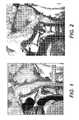
- FIG. 3is a fragmentary perspective view of a system for effecting fusion of the human occipitocervical junction according to a preferred embodiment of the invention
- FIG. 4is a fragmentary cross-sectional view of a portion of the system that is depicted in FIG. 3 ;
- FIG. 5is a fragmentary cross-sectional view depicting a fastening assembly that is constructed according to a preferred embodiment of the invention
- FIG. 6is a fragmentary top plan view of the fastening assembly that is depicted in FIG. 5 ;
- FIG. 7is a diagrammatical depiction of a fastening tool that is designed to be used in conjunction with the fastening assembly that is depicted in FIG. 5 , shown in a first operative position;
- FIG. 8is a diagrammatical depiction of the fastening tool that is shown in FIG. 7 , shown in a second operative position;
- FIG. 9is a fragmentary side elevational view of one component of the system that is depicted in FIG. 3 ;
- FIG. 10is a cross-sectional view depicting certain components of the system that is shown in FIG. 3 ;
- FIG. 11is a fragmentary cross-sectional view depicting certain components of the portion of the system shown FIG. 3 that is depicted in FIG. 10 ;
- FIG. 12is a diagrammatical depiction of certain components of the portion of the system that is shown in FIG. 10 .
- FIG. 13is a fragmentary perspective view of a system for effecting fusion of the human occipitocervical junction according to alternative embodiment of the invention.
- the present inventionrelates to a system and method for stabilizing and fusing the human craniospinal junction.
- the technologyis predicated upon the importance of first, reduction of the deformity at the craniospinal junction, and second of providing the surface area available for and the mileau most conducive to formation of bone fusion. It accomplishes the latter by providing greater bone surface available for bone fusion, and through application of load to the graft.
- the technologyinvolves fewer steps to apply, therefore provides for faster application, and shorter surgery with respect to conventional processes.
- a system 10 for use in the surgical fusion of the human occipitocervical junctionincludes a first bone forming material based structural member 12 and a second bone forming material based structural member 14 .
- the two bone forming material based structural members 12 , 14may be bone grafts that are harvested from another part of the patient's body, such as a rib, grafts from a cadaver, or a material that is constructed and arranged to facilitate the growth of bone.
- the inventionis accordingly not limited to bone, but may use bone substitutes or non-osseous materials to accomplish long-term fixation of the cranium to the spine.
- the two bone forming material based structural members 12 , 14may be fabricated from a metallurgically bonded porous metal coating that is constructed and arranged to encompass and contain bone graft material, such as the material that is marketed under the trade name TRABECULAR METAL by Zimmer Inc. of Warsaw, Ind.
- the two bone forming material based structural members 12 , 14could alternatively be fabricated from a bone forming material such as a bone substitute that is fabricated from a collagen base and contains bone forming materials, or bone enhancing chemicals.
- a bone forming materialcould be embodied as a fabricated mesh that functions as a bone conductor (that a form into which bone growth would occur, or as a bone-like medium such as coralline hydroxyapatite, which serves as an osteoconductor for blood vessel formation and subsequent deposition of bone, which could be injected or poured into the space between the bones to be fused.
- the bone forming materialcould be embodied as a metallic mesh-like substance that encourages or enables bone growth, such as tantalum mesh, which could be molded to fit into the space between the occiput and the spine, a bone allograft or a xenograft.
- the first bone forming material based structural member 12has a first portion 16 that is positioned and biased against the cranial bone so as to promote bone fusion between the cranial bone and the first bone forming material based structural member 12 .
- the second bone forming material based structural member 14has a first portion 18 that is positioned and biased against the cranial bone so as to promote bone fusion between the cranial bone and the second bone forming material based structural member 14 .
- these functions of positioning, support, biasing and promotion of fusionare effected through the use of the unique occipital connection system 23 , which will be described in greater detail below.
- the bone forming material based structural members 12 , 14preferably each have transverse cross-sectional area of approximately 1 cm 2 .
- the first and second bone forming material based structural members 12 , 14further respectively have second portions 20 , 22 that are positioned and biased against at least one cervical vertebral body of a human cervical spine so as to promote bone fusion between the cervical vertebral body and the respective bone forming material based structural member 12 , 14 .
- this functionis effected through the use of the unique vertebral connection system 100 , which will be described in greater detail below.
- the system 10facilitates a fusion between said bone forming material based structural members 12 , 14 and both the C1 and C2 cervical vertebral bodies.
- the inseparable connection system 23includes a plate member 24 that is shaped so as to define an outer edge 26 , an outer surface 28 and an inner surface 30 , as is best shown in FIG. 4 .
- Plate member 24is preferably shaped to define a graft accommodation space 32 between the plate member 24 and the cranium.
- the graft accommodation spaceis preferably defined in part by a flange 25 defined in the plate member 24 by a portion of the plate member 24 including the caudal portion of the outer edge 26 that is elevated away from the cranium with respect to a portion of the inner surface 30 that is contacting the cranium so that the graft accommodation space 32 is open to a space outside of the graft accommodation space 32 .
- the inner surface of flange 25is substantially parallel to and spaced apart from the cranium, defining a graft accommodation space between the inner flange surface and the cranium when the plate member has been secured to the cranium.
- the plate member 24is preferably a monolithic plate, composed of metal, poyetheretherketone (PEEK), bio-absorbable compound, bone or bone substitute.
- the plate member 24preferably has a thickness of more than 1 mm and less than 1 cm at the edges, and may vary in thickness. For instance the plate edge 26 may be 1 mm, but the central part may be increased to 15 mm.
- the plate member 24may be ovoid, rectangular, polyhedral or a composite of straight edges and curves, and thus is not confined to a particular shape or perimeter.
- the plate member 24may be coated or made of a bio-compatible material, or coated with substances which are known to improve or accelerate surface attachment, or to promote bone fusion.
- the plate member 24may or may not contain a metallurgically bonded porous metal coating.
- the plate member 24may be slightly curved so as to be complementary to the curve of the cranium, or may be flat, or may undergo a contouring process by the surgeon or assistant at the time of surgery.
- the flange 25is an elevated contour arising from the plate member 24 . As shown in FIGS. 3-4 , the perimeter of the flange 25 is formed by a free outer flange edge, wherein the entire remainder of the perimeter is directly connected to the plate member. FIGS. 3-4 further show that the perimeter of flange 25 defines the boundary of the graft accommodation space and that the graft accommodation space is configured as a substantially enclosed cavity.
- the flange 25makes available for fusion the underlying cranial surface; the elevation of the flange 25 exposes the cranial bone surface to the overlying bone graft.
- the flange 25may be constructed from the same material as the remainder of the plate member 24 , or it may be a constructed as a separate component that is attachable to the plate member 24 .
- the purpose of the flange 25is to incorporate, to enclose or to provide a fulcrum in which bone graft materials or substitutes, or other materials, may be held for the purpose of achieving a bone union or other permanent rigid or non-rigid attachment between the cranium and the spine.
- the flange 25may be non-perforate, or single or multiply perforate, and could be composed of a mesh or mesh-like construction.
- the flange 25is preferably perforated to allow in-growth of bodily tissue or blood vessels.
- the flangehas a perforated plus non-perforated surface area of more than 15% of the area of the plate component.
- the thickness of the flange 25is 0.5 to 5 mm thickness.
- the purpose of the flange 25is to entrap the bone forming substances or other structural members in close union with the underlying cranium, and to facilitate in the case of bone, morphogenesis through application of load; that is, through pressure and stabilization of the bone forming substances to enhance the milieu favoring new bone formation.
- flange 25has a concave configuration adapted to form a pocket with the cranium when plate member 24 is secured to the cranium.
- the flange 25may have a facility to be mechanically altered in shape to further compress the graft.
- the flange 25will preferably rise from the plane of the portion of the plate member 24 that contacts the cranial bone for a distance that is more than about 5 mm, to allow placement of a thickness of material that is adequate to provide stability for growth. It is envisioned that malleable, or woven-bone forming substrates could be used to promote fusion, or indeed provide the scaffolding itself for fusion. Conversely, other materials could be used beneath the flange 25 to provide non-osseous, non-rigid fixation.
- Flange 25will preferably allow the passage or inset of rods, plates or other materials for connecting the cranial plate to the spine. The purpose of this is to lower the profile of the rod, and to minimize the potential deformity of overlying tissue.
- a rodmay pass through a perforation in a mesh of the flange to connect to the triple screw.
- the flangemay have a groove, a pop-out section or possess the faculty of perforability to allow passage of the stabilization element connecting cranium to spine.
- the flange 25might serve to provide attachment for a non-osseous union between the cranium and spine.
- the flange 25thus may have both a physiological function and a mechanical function.
- Flange 25is envisioned in the preferred embodiment to arise from the lower aspect of the plate member 24 .
- alternate embodimentswould allow positioning of a single or multiple flanges in various locations, such as the middle, the upper or the sides of the plate.
- the flangeshould not be construed to exist only as an elevation from the lower edge of the plate, but, for instance, may be centered on the plate; a rim of plate could thus fully encompass the flange(s).
- flange 25Whilst the preferred embodiment of the flange 25 is curved to minimize profile by conforming to anatomic contour, alternate forms may include box-like constructs, or even a multiplicity of shapes and sizes that could be chosen for a given application, and then be secondarily attached to the plate.
- a low profile, curved flangecould be applied to the plate over the cranium of an asthenic child where the thickness of skin and muscle contraindicate thickness of construct; another embodiment, for a larger person, may be a larger box-like adaptation designed to facilitate the incorporation of a more rectanguloid, synthetic bone-forming substance or other non-osseous compound. It is thus envisioned that a multiplicity of options to accomplish different goals in persons (or other species of animal) of different morphology.
- the first portion 18 of the second bone material based structural member 14is preferably positioned within the graft accommodation space 32 defined by the flange 25 so that the inner surface 30 of the plate member 24 is biased to provide compressive pressure against the second bone material based structural member 14 .
- This compressionwill facilitate bone fusion between the second bone material based structural member 14 and the cranium.
- the first portion 16 of the first bone material based structural member 12is similarly positioned within the graft accommodation space 32 and impressively biased against the cranial bone to promote bone fusion.
- the plate member 24could be fabricated so as to include more than one graft accommodation space, so that each of the two structural members 12 , 14 could be separately positioned within different accommodation spaces that are defined by the inner surface 30 of the plate member 24 .
- the inner surface 30 of the plate member 24is preferably composed of a material that promotes fusion to bone. This could be accomplished by coating the plate member 24 with anyone of a number of conventional bone growth promoting substances or by fabricating the plate member 24 from a porous material that is constructed and arranged to encompass and contain bone graft material, such as the TRABECULAR METAL material described above.
- Plate member 24further preferably has a plurality of perforations 34 defined therein. Perforations 34 preferably have a minimum diameter of at least 400 microns, so as to best facilitate the growth of blood vessels within the newly formed bone tissue.
- a portion 48 of the outer surface 28 of the plate member 24may be grooved in order to accommodate instrumentation, as will be described in greater detail below.
- Plate member 24preferably has a plurality of pre-drilled threaded mounting holes 36 , 38 , 40 , 44 , 46 , 72 defined therein for facilitating attachment of the plate member 24 to first portions 54 , 58 of first and second support rods 50 , 52 by means of first and second fastening assemblies 62 , 64 , respectively.
- the plate member 24will therefore preferably include manifold screw holes in order to permit the support rods 50 , 52 to be secured to the plate member 24 and locations that are most suitable for an individual patient.
- a central screw hole 40will serve to anchor a central plate screw 42 .
- the central screw hole(s)lie(s) approximately in the midline of the patient's body and cranium in order to permit placement of screw(s) into the thickest part of the skull, which usually runs from the inion to the opisthion. These holes may be threaded, partially threaded or not threaded.
- additional holes 38 , 44 , 46 , 72will be positioned to receive additional screws, called the triple screws 70 .
- the triple screws 70 engaged in the platewill serve to anchor the stabilization elements (rods, plates or other) from the cervical spine.
- These holesmay be single or multiple; the holes may cluster, may overlap, may be placed in an arc, or contiguously or in separately locations.
- the holesmay be placed around the edge of the flange, or on the flat portion of the plate. These holes may be reinforced with extra thickness, and may be threaded or not.
- Second portions 56 , 60 of the first and second support rods 50 , 52are secured to the cervical spine of the patient, as will be described in greater detail below.
- the central plate screw 42provides primary attachment of the plate to the skull. It is robust, cortically threaded, of variable length, preferably having a month within a range of about 7 mm to about 12 mm.
- the central plate screw 42preferably has a thickness within a range of about 2 mm to about 10 mm, with a blunted end. It may have a spiral lock feature that locks the screw 42 into the plate member 24 , or not. It may be lagged to provide increased loading pressure on the plate member 24 , or not.
- Itcan be made of titanium alloy, of bone, or of a bone forming or bone compatible substance. For example, a ceramic, or hydroxyl-apatite composite or metal alloy/bone composite could be used.
- a screw/rivetcould be used in lieu of the central plate screw 42 for rapid application.
- the screw or screw/rivetwould preferably have torque strength of greater than 35 inch lb and generate sufficient pullout strength to prevent dislodgement from the cortex.
- the screw or screw/rivetwould be placed near the middle of the plate member 24 , and be fashioned to pass through the central screw hole 40 on the plate member 24 .
- the first and second support rods 50 , 52provide the main structural connection between the cranium and the upper cervical spine during the immediate postoperative period.
- Support rods 50 , 52are preferably standard titanium rods, approximately of 3-4 mm gauge, bent to conform to the correct craniospinal angle. The salient differences from other rods currently available are two-fold.
- the firstis an angle reflecting the corrected reduction of the angle ( ⁇ angle, FIG. 9 ) between the cranium and that of the spine; in the preferred embodiment this will be pre-set within a range of about 75° to about 90°.
- the first and second support rodsare contoured to ensure a postoperative craniospinal relationship that confers a clivo-axial angle (the angle between the dorsum of the second cervical vertebra and the dorsum of the clivus) approaching about 145-165°, and more preferably about 155 to 165°.
- the degree of ventral brainstem compressionshould be rendered close to zero, by virtue of the reduction of angulation between the cranium and spine, and in some cases by the posterior translation of cranium upon spine.
- the craniospinal support rods 50 , 52will have a pre-established rise option (the ⁇ rise, FIG. 9 ), to accommodate the non-linearity of the level of the posterior ring of the first cervical vertebra C1 to the surface of the lamina of C2 and lateral mass of C3. Accordingly, the presence of the pre-established ⁇ rise will allow the support rods 50 , 52 to contact the C1 and C2 laminae.
- Fastening assembly 62is shown in greater detail in FIG. 5 .
- an unthreaded hole 68is defined in the first portion 54 of the first support rod 50 and a threaded hole 72 is provided in the plate member 24 .
- Fastening assembly 62advantageously includes a unique triple screw 70 that has a first threaded portion 70 at an intermediate section thereof that is sized and pitched to mate with the threaded hole 72 in the plate member 24 and a second threaded portion 76 at a lower section thereof that is constructed and arranged to be screwed into the cranial bone 78 .
- Triple screws 70have the unique characteristic of deriving stability from fixation within the skull, the plate member 24 and around the rod or plate that connects the cranium to the spine.
- the triple screw 70is tri-purposive: first, it connects the plate to the cranium; second, it connects the cranium to the craniospinal connecting devices; third, it eliminates plate torque around the central screw 42 . In so doing, it eliminates one of the steps common to all other craniospinal devices: that of an additional and independent means of attaching the plate member 24 to the craniospinal rod or plate connector.
- Triple screws 70are so-called because they possess three functional portions of the screw length: a threaded portion for attachment to the cranial bone 78 , a threaded, or non threaded, portion to engage the plate member 24 , and a threaded portion for attaching the support rod 50 .
- the central or intermediate portionmay be threaded to enhance binding to the plate member 24 , or non-threaded to allow a lag effect upon the plate member 24 , in order to allow the insertion of the screw to tighten the plate down to the cranial bone 78 , depending upon the requirements of the particular stabilization.
- the triple screws 70may be placed in one of many potential screw holes on each side of the plate member 24 , in order to accommodate to the variability of the system that attaches the cranium to the cervical spine. Whilst the triple screws 70 are shown in the upper portion of the plate in the illustrated embodiment, they may in another embodiment be placed in the lower aspect of the plate. They are not limited to being positioned at lateral opposite sides of the plate member 24 , but may be placed near the middle of the plate member 24 . The triple screw 70 can be turned to any direction to accommodate the craniospinal rod or connector system.
- the triple screw 70will preferably be inserted through the plate and screwed into the skull.
- the triple screw 70will provide increased stability to the plate and rod system by virtue of the combined fixation of the screw within the plate and the skull.
- the triple screw 70may be threaded at the level of the skull with a cortical or cancellous thread, or could in another embodiment utilize a rivet-type fixation. In any event, the internal portion of the screw is firmly fixated to the skull.
- Triple screw 70further includes a third threaded portion 80 at an upper portion thereof that is sized in pitch to mate with an internally threaded hexagonal nut 82 .
- FIG. 6which provides a top plan view of the fastening assembly 62 , an upper surface of the triple screw 70 is provided with a slot for receiving a screwdriver blade.
- FIGS. 7 and 8depict a unique tool 86 that is constructed and arranged to be used in conjunction with the fastening assembly 62 and the triple screw 70 .
- Tool 86includes a handle 88 and a shaft 90 that may be provided with a universal joint 92 for accessibility purposes, e.g. to accommodate non-orthogonal placement of the screw. For instance, if access to the triple screw 70 is encumbered by a patient's diverence, the screw may be inserted at an angle.
- a screwdriver blade 94is provided at a distal end of the shaft 90 and is preferably sized and shaped to be effectively received by the slot 84 that is defined in the upper surface of the triple screw 70 .
- tool 86preferably includes a sleeve 96 that is slidable upwardly and downwardly on the lower portion of the shaft 90 between a first retracted position that is shown in FIG. 7 and a second, extended operative position that is shown in FIG. 8 .
- Sleeve 96is shaped to define an internally threaded socket that mates with the external thread 80 of the triple screw 70 .
- Sleeve 96is further mounted to the shaft 90 so that it is prevented from rotating with respect to the shaft 90 . Accordingly, a surgeon may use the tool 86 in the operative position that is shown in FIG.
- system 10further includes a unique vertical connection system 100 for positioning and biasing the second portions 20 , 22 of the first and second bone forming material based structural members 12 , 14 against at least one cervical vertebral body of a human cervical spine so as to promote bone fusion between the cervical vertebral body and the respective bone forming material based structural member 12 , 14 .
- the vertebral connection system 100includes a transverse connector 110 that is positioned to compress the first bone material based structural member 20 and the second bone material based structural member 22 against a vertebral body such as the vertebral body C2 that is depicted in FIG. 10 .
- the transverse connector 110serves several purposes. First, the transverse connector 110 holds the graft material (the bone, bone substitute or other non-osseous material) into close contact, and usually under pressure, with the underlying spinal vertebrae, to facilitate in-growth of blood vessels or other tissue, as is dramatically depicted in FIGS. 10 and 11 . Second, the transverse connector 110 stabilizes the two sides of the system 10 , connecting the respective support rods 50 , 52 from one side to that of the other, thereby decreasing the potential for toggling.
- the graft materialthe bone, bone substitute or other non-osseous material
- the transverse connector 110is connected to the first structural support rod 50 at one portion thereof that includes a first clamping structure 112 for releasably clamping one end of the transverse connector 110 to the first structural support rod 50 .
- the first clamping structure 112includes a curved plate portion 116 that curves about most of the circumference of a first structural support rod 50 .
- a screw 120extends through first and second holes that are defined in the curved plate portion 116 for tightening and loosening the first clamping mechanism 112 with respect to the first structural support rod 50 .
- the transverse connector 110is connected to the second structural support rod 52 at a second portion thereof that includes a second clamping mechanism 114 for releasably clamping a second, opposite end of the transverse connector 110 to the second structural support rod 52 .
- the second clamping structure 114includes a curved plate portion 118 that curves about most of the circumference of the second structural support rod 52 .
- a screw 122extends through first and second holes that are defined in the curved plate portion 118 .
- the curved plate portions 116 , 118 of the respective clamping mechanisms 112 , 114preferably extend around the circumference of the respective support rod 50 , 52 as viewed in transverse cross-section for an angular distance of at least three radians.
- the clamping screws 120 , 122are preferably positioned on the medial side of the respective support rod 50 , 52 .
- the transverse connector 110is preferably curved so as to be concave on a side thereof that is positioned to contact the first bone material based structural member 20 and said second bone based structural member 22 .
- the transverse connector 110further preferably includes structure for permitting adjustment of a length of the transverse connector 110 , whereby a lateral spacing distance between said first and second laterally spaced structural support rods may be adjusted. In the preferred embodiment, this is accomplished by constructing the transverse connector 110 out of two separate components that are attachable to each other, specifically a first curved connector portion 124 and a second curved connector portion 126 , as is best shown in FIG. 12 .
- the first connector portion 124has a plurality of adjustment holes 130 defined therein while the second connector portion 126 similarly has a plurality of adjustment holes 132 defined therein.
- a top-loading screw member 128which is best shown in FIG. 10 , is provided for securing the first connector portion 124 to the second connector portion 126 and is preferably applied centrally in a precise manner in order to stabilize the first and second connector portions 124 , 126 .
- Screw member 128is preferably although not necessarily a lock screw having a snap off head.
- a Vernier scale optionmay be used to generate the best precise fit, but other adaptations may be used, with the most important requirement being that a secure fit is created.
- the graft loading transverse connector component arms 124 , 126are preferably curved, and may possess a plurality of curve sizes to accommodate the specific graft or implanted material size. In one possible alternative embodiment, the transverse connector arms are straight with a rise to accommodate the underlying material.
- the surgically implantable instrumentation of the system 10may alternatively be fabricated from a bioabsorbable material that progressively loses its strength and mass over time as it is absorbed into the human body.
- the ideal bioabsorbable materialwould have a composition that would retain sufficient strength for a sufficient period of time for adequate bone fusion and bone mass to develop so that the first and second bone forming material based structural members 12 , 14 would provide adequate structural strength to maintain the fusion of the human occipitocervical junction at all times and under all foreseeable circumstances.
- a system 140that is constructed according to an alternative embodiment of the invention includes an integrated fixation member 142 having a plate portion 144 and first and second appendages 146 , 148 that are integral and preferably unitary with the plate portion 144 .
- the appendages 146 , 148would intimately relate to the posterior ring of C1 (the first vertebra and the lateral mass of C2, C3 and to any of the lower vertebrae, even as low as the thoracic vertebrae
- the goal of the monolithic designwould be to simplify and increase the efficiency of application and stabilization of the device to the craniospinal junction.
- Plate portion 144is preferably constructed identically to the plate portion described above with reference to the previously described embodiment except as is described otherwise herein.
- the first and second appendages 146 , 148are preferably rigid and in the preferred embodiment are fabricated from a pair of generally parallel extending rod members 150 , 152 .
- Appendages 146 , 148are preferably preformed as described above with reference to the first embodiment of the invention so as to be bent at an angle reflecting the corrected reduction of the angle ( ⁇ angle, FIG. 9 ) between the cranium and that of the spine, which in the preferred embodiment this will be pre-set within a range of about 75° to about 90°.
- the first and second integrated appendages 146 , 148are contoured to ensure a postoperative craniospinal relationship that confers a clivo-axial angle (the angle between the dorsum of the second cervical vertebra and the dorsum of the clivus) approaching about 155-165° and more preferably about 155-165°.
- the degree of ventral brainstem compressionshould be rendered zero, by virtue of the reduction of angulation between the cranium and spine, and in some cases by the posterior translation of cranium upon spine.
- the integrated appendages 146 , 148preferably incorporate a pre-established rise option (the ⁇ rise, described above with reference to FIG. 9 ), to accommodate the non-linearity of the level of the posterior ring of the first cervical vertebra C1 to the surface of the lamina of C2 and lateral mass of C3.
- the presence of the pre-established ⁇ risewill allow the integrated appendages 146 , 148 to contact the C1 and C2 laminae, as shown in FIG. 13 .
- adjustment slots 156 , 158are provided in the first and second appendages 146 , 148 , respectively, to permit positional adjustment of the integrated fixation member 142 with respect to the pedicle screws 102 , 104 that are used to secure the first and second appendages 146 , 148 , respectively, to the C2 vertebrae.
- adjustment slot 158as well as adjustment slot 156 may include a plurality of prepositioned apertures or adjustment holes 160 , 162 to permit indexing of the pedicle screw 104 within the appendage 148 or variability of screw purchase.
- adjustment slots 154may be provided in the respective portions of the first and second appendages 146 , 148 that are constructed and arranged to be secured to the C1 vertebrae by pedicle screws 106 , 108 .
- This portion of the appendages 146 , 148is preferably constructed so as to be slightly flared at the C1 vertebrae to allow lateral variability.
- the appendages 146 , 148may be solid, tubular, porous or even a metallurgically bonded porous metal coating that is constructed and arranged to encompass and contain bone graft material, such as the material that is marketed under the trade name TRABECULAR METAL by Zimmer Inc. of Warsaw, Ind.
- a method for achieving occipitocervical fusionwill now be described.
- the patientis first positioned prone with a Mayfield pin headrest in an appropriate sterile surgical environment.
- the posterior cranium (subocciput)will then be surgically exposed.
- the suboccipital bonewill then preferably be lightly drilled or sculpted in order to create a flat and even surface for the positioning of the plate member 24 .
- the plate member 24will then be aligned with the long axis of the patient's body and will be positioned symmetrically about the midline axis, so that the central screw hole 40 is preferably bisected by the midline axis of the patient's cranium as viewed in rear elevation. The center of the central screw hole 40 will then be marked on the cranium, and the plate member 24 will be removed.
- a central holewill then be surgically drilled in the cranium, preferably to a depth of 5-10 mm. using a high speed drill, then by a conventional surgical hand drill to complete the drilling, preferably to a total depth of between about 8 mm to about 12 mm.
- the screw holewill be tapped to a depth that is about 1 mm. longer than the screw to be used. (For example, for a 10 mm screw, tap to 11 mm depth).
- the plate member 24will then be repositioned on the midline.
- the central cortical screw 42will then be inserted into the tapped hole and tightened, lagging down the plate member 24 to achieve solid fixation.
- the left pre-contoured support rod 50is loosely positioned within the first clamping mechanism on 12 of the transverse connector 110 and is secured to the left C1 and C2 screws 102 , 106 .
- the triple screw position for the first fastening assembly 62 that best aligns with the pre-contoured occipito-cervical rod 50is then selected.
- the triple screw purchase selectedis then drilled in the cranium.
- the lateral screw purchasemay then be tapped if it is not been pre-threaded.
- the triple screw 70is inserted.
- the Mayfield headholderis then released, and an open reduction of the craniocervical junction is performed under fluoroscopy and under direct inspection. It is ensured that the abnormal angulation (kyphosis) of the craniospinal angle, and any abnormal translation of the skull is reduced, and that there is no rotation or lateral bending and no subluxation at lower spinal levels.
- the head-holderis then relocked.
- the clivioaxial angleis then measured with the goal of achieving an optimal clivioaxial angle of 150° to 165°.
- the support rods 50 , 52are then placed into the triple screws 70 within the respective fastening assembly 62 , 64 and the hex nuts 82 are placed over the screws 70 and tightened.
- the exposed suboccipital bone, the posterior ring of C1 and the lamina and facet joints of C2are then surgically decorticated.
- the first portions 16 , 18 of the first and second bone forming material based structural member 12 , 14are then inserted into the graft accommodation space 32 that is defined between the plate member 24 and the cranium, as is best shown in FIG. 4 .
- the cephalad part of the bone forming material based structural membershould be fashioned to fit precisely and under pressure beneath the flange 25 of the plate member 24 .
- the caudal edge 26 of the plate member 24may now be bent down towards the cranium to further compress the graft.
- the caudal end of the graftshould lie on the decorticated C1 and C2 (and lower levels where indicated) dorsal elements.
- the graft loading transverse connectoris then positioned to hold down, under pressure, the portions of the first and second bone forming material based structural members 12 , 14 that are positioned over and against the C1 and C2 dorsal elements. This is best illustrated in FIGS. 10 and 11 .
- the locking screws 120 , 122are then tightened on the transverse connector.
- Demineralized bone matrixmay then be applied to the fusion areas and more cancellous bone may be applied to complete the fusion.
- a layered wound closureis then performed conventionally over a drain.
- a method according to an alternative embodiment of the inventionwould utilize the integrated fixation member 142 that is depicted in FIG. 13 .
- the preferred stepsare preferably slightly reordered. First, placement of the screws into the lateral mass or ring or C1 and into the lateral mass or pedicle of C2, or into the lateral masses of the lower cervical or thoracic vertebrae would be performed.
- the monolithic construct including the plate portion 144 and the integrated appendages 146 , 148which are surrogates for the rods 56 and 58 described with reference to the first embodiment of the invention, is applied over the screw heads.
- the plate portion 144is screwed to the skull 23 with the central screw 42 .
- the top loading nuts 106 , 108are then tightened down over the screw heads of the vertebral screws.
- this methodis identical to the method first described above.
Landscapes
- Health & Medical Sciences (AREA)
- Orthopedic Medicine & Surgery (AREA)
- Surgery (AREA)
- Life Sciences & Earth Sciences (AREA)
- Biomedical Technology (AREA)
- Public Health (AREA)
- Neurology (AREA)
- Engineering & Computer Science (AREA)
- Veterinary Medicine (AREA)
- Heart & Thoracic Surgery (AREA)
- Medical Informatics (AREA)
- Molecular Biology (AREA)
- Animal Behavior & Ethology (AREA)
- General Health & Medical Sciences (AREA)
- Nuclear Medicine, Radiotherapy & Molecular Imaging (AREA)
- Neurosurgery (AREA)
- Prostheses (AREA)
- Surgical Instruments (AREA)
Abstract
Description
Claims (26)
Priority Applications (6)
| Application Number | Priority Date | Filing Date | Title |
|---|---|---|---|
| US11/832,646US8083743B2 (en) | 2007-01-29 | 2007-08-01 | Craniospinal fusion method and apparatus |
| US12/234,521US8403965B2 (en) | 2007-01-29 | 2008-09-19 | Vertebra attachment method and system |
| US12/688,848US8182511B2 (en) | 2007-01-29 | 2010-01-15 | Craniospinal fusion method and apparatus |
| US13/163,650US8858470B2 (en) | 2007-01-29 | 2011-06-17 | Method for treating a neurological disorder |
| US13/335,248US9107717B2 (en) | 2007-01-29 | 2011-12-22 | Craniospinal fusion method and apparatus |
| US14/815,044US9827023B2 (en) | 2007-01-29 | 2015-07-31 | Craniospinal fusion method and apparatus |
Applications Claiming Priority (2)
| Application Number | Priority Date | Filing Date | Title |
|---|---|---|---|
| US88702207P | 2007-01-29 | 2007-01-29 | |
| US11/832,646US8083743B2 (en) | 2007-01-29 | 2007-08-01 | Craniospinal fusion method and apparatus |
Related Child Applications (3)
| Application Number | Title | Priority Date | Filing Date |
|---|---|---|---|
| US11/832,643Continuation-In-PartUS8043342B2 (en) | 2007-01-29 | 2007-08-01 | Craniospinal fusion method and apparatus |
| US12/688,848Continuation-In-PartUS8182511B2 (en) | 2007-01-29 | 2010-01-15 | Craniospinal fusion method and apparatus |
| US13/335,248ContinuationUS9107717B2 (en) | 2007-01-29 | 2011-12-22 | Craniospinal fusion method and apparatus |
Publications (2)
| Publication Number | Publication Date |
|---|---|
| US20080234755A1 US20080234755A1 (en) | 2008-09-25 |
| US8083743B2true US8083743B2 (en) | 2011-12-27 |
Family
ID=39775523
Family Applications (3)
| Application Number | Title | Priority Date | Filing Date |
|---|---|---|---|
| US11/832,646Active2029-01-01US8083743B2 (en) | 2007-01-29 | 2007-08-01 | Craniospinal fusion method and apparatus |
| US11/832,643Active2028-08-26US8043342B2 (en) | 2007-01-29 | 2007-08-01 | Craniospinal fusion method and apparatus |
| US13/335,248Active2029-10-08US9107717B2 (en) | 2007-01-29 | 2011-12-22 | Craniospinal fusion method and apparatus |
Family Applications After (2)
| Application Number | Title | Priority Date | Filing Date |
|---|---|---|---|
| US11/832,643Active2028-08-26US8043342B2 (en) | 2007-01-29 | 2007-08-01 | Craniospinal fusion method and apparatus |
| US13/335,248Active2029-10-08US9107717B2 (en) | 2007-01-29 | 2011-12-22 | Craniospinal fusion method and apparatus |
Country Status (1)
| Country | Link |
|---|---|
| US (3) | US8083743B2 (en) |
Cited By (3)
| Publication number | Priority date | Publication date | Assignee | Title |
|---|---|---|---|---|
| US20110004250A1 (en)* | 2007-11-29 | 2011-01-06 | Uribe Juan S | Apparatus for Occipital-Cervical Fixation Enabling Supplemental Occipital Bone Fixation |
| US20120116455A1 (en)* | 2007-01-29 | 2012-05-10 | Polaris Biotechnology, Inc. | Craniospinal fusion method and apparatus |
| US9827023B2 (en) | 2007-01-29 | 2017-11-28 | Life Spine, Inc. | Craniospinal fusion method and apparatus |
Families Citing this family (27)
| Publication number | Priority date | Publication date | Assignee | Title |
|---|---|---|---|---|
| US8182511B2 (en) | 2007-01-29 | 2012-05-22 | Polaris Biotechnology, Inc. | Craniospinal fusion method and apparatus |
| US8403965B2 (en) | 2007-01-29 | 2013-03-26 | Polaris Biotechnology, Inc. | Vertebra attachment method and system |
| US8556939B2 (en)* | 2008-01-08 | 2013-10-15 | Fraser Cummins Henderson | Mathematical relationship of strain, neurological dysfunction and abnormal behavior resulting from neurological dysfunction of the brainstem |
| US20090036894A1 (en)* | 2007-01-29 | 2009-02-05 | Polaris Biotechnology, Inc. | Method of treating a neurological condition through correction and stabilization of the clivo-axial angle |
| US9204908B2 (en) | 2007-07-26 | 2015-12-08 | Dynamic Spine, Llc | Segmental orthopedic device for spinal elongation and for treatment of scoliosis |
| US8790380B2 (en)* | 2007-07-26 | 2014-07-29 | Dynamic Spine, Llc | Segmental orthopaedic device for spinal elongation and for treatment of scoliosis |
| WO2009089395A2 (en)* | 2008-01-08 | 2009-07-16 | Polaris Biotechnology, Inc. | Osteointegration apparatus |
| EP2330991B1 (en)* | 2008-07-02 | 2015-09-02 | Life Spine, Inc. | Craniospinal fusion method and apparatus |
| US20100222825A1 (en)* | 2009-03-02 | 2010-09-02 | Warsaw Orthopedic, Inc. | Side-loading occipital vertebral fixation system |
| US9439685B2 (en) | 2009-05-12 | 2016-09-13 | Bullard Spine, Llc | Multi-layer osteoinductive, osteogenic, and osteoconductive carrier |
| AU2011264818B2 (en) | 2010-06-10 | 2015-06-18 | Globus Medical, Inc. | Low-profile, uniplanar bone screw |
| US9387013B1 (en) | 2011-03-01 | 2016-07-12 | Nuvasive, Inc. | Posterior cervical fixation system |
| US8668723B2 (en) | 2011-07-19 | 2014-03-11 | Neurostructures, Inc. | Anterior cervical plate |
| EP3384864A1 (en) | 2013-01-29 | 2018-10-10 | III Chester Evan Sutterlin | Occipital plate assemblies with polyaxial head connectors |
| WO2014199398A2 (en)* | 2013-06-10 | 2014-12-18 | All India Institute Of Medical Sciences | Novel techniques for reduction of basilar invagination and atlanto axial dislocation and surgical instruments thereof |
| US9629664B2 (en) | 2014-01-20 | 2017-04-25 | Neurostructures, Inc. | Anterior cervical plate |
| US9486250B2 (en) | 2014-02-20 | 2016-11-08 | Mastros Innovations, LLC. | Lateral plate |
| US10512547B2 (en) | 2017-05-04 | 2019-12-24 | Neurostructures, Inc. | Interbody spacer |
| US10980641B2 (en) | 2017-05-04 | 2021-04-20 | Neurostructures, Inc. | Interbody spacer |
| US10624678B2 (en) | 2017-06-20 | 2020-04-21 | A-Line Orthopaedics Corporation | Clamp implant for posterior arch of the atlas |
| US11076892B2 (en) | 2018-08-03 | 2021-08-03 | Neurostructures, Inc. | Anterior cervical plate |
| US11071629B2 (en) | 2018-10-13 | 2021-07-27 | Neurostructures Inc. | Interbody spacer |
| CN109700517B (en)* | 2019-02-01 | 2024-03-19 | 西安增材制造国家研究院有限公司 | Auxiliary resetting device for atlantoaxial dislocation and manufacturing method thereof |
| US11382761B2 (en) | 2020-04-11 | 2022-07-12 | Neurostructures, Inc. | Expandable interbody spacer |
| US11304817B2 (en) | 2020-06-05 | 2022-04-19 | Neurostructures, Inc. | Expandable interbody spacer |
| US11717419B2 (en) | 2020-12-10 | 2023-08-08 | Neurostructures, Inc. | Expandable interbody spacer |
| CN114129308B (en)* | 2021-11-15 | 2025-01-10 | 中国人民解放军空军军医大学 | A 3D printed fixed fusion integrated posterior cervical occipital fusion prosthesis |
Citations (86)
| Publication number | Priority date | Publication date | Assignee | Title |
|---|---|---|---|---|
| US1135699A (en) | 1914-10-01 | 1915-04-13 | Margaret Knauber | Adjustable fixture stud and support. |
| US1739009A (en)* | 1929-08-07 | 1929-12-10 | Lorber Charles | Flag holder |
| US1750769A (en) | 1922-07-29 | 1930-03-18 | Ohio Brass Co | Insulator pin |
| US2669405A (en)* | 1949-08-01 | 1954-02-16 | Donnelly Electronices Inc | Television antenna |
| US3073022A (en)* | 1959-04-03 | 1963-01-15 | Gen Motors Corp | Shot-peening treatments |
| US4456005A (en) | 1982-09-30 | 1984-06-26 | Lichty Terry K | External compression bone fixation device |
| US4653481A (en) | 1985-07-24 | 1987-03-31 | Howland Robert S | Advanced spine fixation system and method |
| US4655199A (en) | 1985-03-29 | 1987-04-07 | Acromed Corporation | Spinal column straightening apparatus |
| US4762122A (en)* | 1987-02-06 | 1988-08-09 | Barclay Slocum | Device and method for pelvic osteotomy fixation |
| US4790702A (en) | 1986-03-27 | 1988-12-13 | Maganias Nicholas H | Nut and bolt assembly |
| US4800874A (en)* | 1986-07-15 | 1989-01-31 | Vereinigte Edelstahlwerke A.G. | Anatomical bone plate and/or transfixion plate |
| US4805602A (en) | 1986-11-03 | 1989-02-21 | Danninger Medical Technology | Transpedicular screw and rod system |
| US5030220A (en) | 1990-03-29 | 1991-07-09 | Advanced Spine Fixation Systems Incorporated | Spine fixation system |
| US5034011A (en) | 1990-08-09 | 1991-07-23 | Advanced Spine Fixation Systems Incorporated | Segmental instrumentation of the posterior spine |
| US5129900A (en) | 1990-07-24 | 1992-07-14 | Acromed Corporation | Spinal column retaining method and apparatus |
| US5133716A (en)* | 1990-11-07 | 1992-07-28 | Codespi Corporation | Device for correction of spinal deformities |
| US5176680A (en) | 1990-02-08 | 1993-01-05 | Vignaud Jean Louis | Device for the adjustable fixing of spinal osteosynthesis rods |
| US5269784A (en) | 1991-12-10 | 1993-12-14 | Synthes (U.S.A.) | Screw nut for plate osteosynthesis |
| US5360429A (en)* | 1992-02-20 | 1994-11-01 | Jbs Societe Anonyme | Device for straightening, fixing, compressing, and elongating cervical vertebrae |
| US5470333A (en)* | 1993-03-11 | 1995-11-28 | Danek Medical, Inc. | System for stabilizing the cervical and the lumbar region of the spine |
| US5507745A (en)* | 1994-02-18 | 1996-04-16 | Sofamor, S.N.C. | Occipito-cervical osteosynthesis instrumentation |
| US5545228A (en) | 1991-08-15 | 1996-08-13 | Smith & Nephew Richards Inc. | Offset bone bolt |
| US5545164A (en) | 1992-12-28 | 1996-08-13 | Advanced Spine Fixation Systems, Incorporated | Occipital clamp assembly for cervical spine rod fixation |
| US5611354A (en)* | 1992-11-12 | 1997-03-18 | Alleyne; Neville | Cardiac protection device |
| US5643261A (en) | 1994-03-10 | 1997-07-01 | Schafer Micomed Gmbh | Osteosynthesis device |
| US5653710A (en) | 1993-11-23 | 1997-08-05 | Haerle; Anton | Osteosynthetic force transmitting member |
| US5733285A (en) | 1995-07-13 | 1998-03-31 | Fastenetix, Llc | Polyaxial locking mechanism |
| US5800435A (en)* | 1996-10-09 | 1998-09-01 | Techsys, Llc | Modular spinal plate for use with modular polyaxial locking pedicle screws |
| US5968047A (en) | 1996-04-05 | 1999-10-19 | Reed; Thomas Mills | Fixation devices |
| US6039738A (en) | 1997-07-03 | 2000-03-21 | Depuy Orthopaedics, Inc. | Fastener |
| US6056753A (en) | 1998-07-13 | 2000-05-02 | Jackson; Roger P. | Set screw for use with osteosynthesis apparatus |
| US6059786A (en) | 1998-10-22 | 2000-05-09 | Jackson; Roger P. | Set screw for medical implants |
| US6080579A (en)* | 1997-11-26 | 2000-06-27 | Charlotte-Mecklenburg Hospital Authority | Method for producing human intervertebral disc cells |
| US6125526A (en) | 1999-05-12 | 2000-10-03 | Robert Bosch Corporation | Method of fastening a first member to a second member |
| US6129730A (en) | 1999-02-10 | 2000-10-10 | Depuy Acromed, Inc. | Bi-fed offset pitch bone screw |
| US6129728A (en) | 1998-02-18 | 2000-10-10 | Walter Lorenz Surgical, Inc. | Method and apparatus for mandibular osteosynthesis |
| US6146382A (en) | 1998-09-23 | 2000-11-14 | Spinal Concepts, Inc. | Occipito-cervical stabilization system and method |
| US6179841B1 (en) | 1997-01-06 | 2001-01-30 | Medtronic Sofamor Danek, Incorporated | Set screw for use with osteosynthesis apparatus |
| US6193719B1 (en) | 1995-08-24 | 2001-02-27 | Sofamor S.N.C. | Threaded clamping plug for interconnecting two implants of a spinal osteosynthesis instrumentation or other implants |
| US6221073B1 (en)* | 1999-08-20 | 2001-04-24 | Kinetikos Medical, Inc. | Wrist fusion apparatus and method |
| US6224596B1 (en) | 1997-01-06 | 2001-05-01 | Roger P. Jackson | Set screw for use with osteosynthesis apparatus |
| US6319254B1 (en) | 1999-04-22 | 2001-11-20 | Newdeal | Compression osteosynthesis screw, and an ancillaty device for use therewith |
| US6325803B1 (en) | 1998-02-18 | 2001-12-04 | Walter Lorenz Surgical, Inc. | Method and apparatus for mandibular osteosynthesis |
| US6355043B1 (en) | 1999-03-01 | 2002-03-12 | Sulzer Orthopedics Ltd. | Bone screw for anchoring a marrow nail |
| US6423067B1 (en) | 1999-04-29 | 2002-07-23 | Theken Surgical Llc | Nonlinear lag screw with captive driving device |
| US20020120268A1 (en) | 2001-02-21 | 2002-08-29 | Roger Berger | Occipital plate and system for spinal stabilization |
| US6454772B1 (en) | 2000-12-08 | 2002-09-24 | Roger P. Jackson | Set screw for medical implant with gripping side slots |
| US6454768B1 (en) | 2000-12-05 | 2002-09-24 | Roger P. Jackson | Removable gripping set screw |
| US6520990B1 (en) | 1990-10-05 | 2003-02-18 | Sdgi Holdings, Inc. | Lateral fixation plates for a spinal system |
| US6524315B1 (en)* | 2000-08-08 | 2003-02-25 | Depuy Acromed, Inc. | Orthopaedic rod/plate locking mechanism |
| US6565566B1 (en) | 2000-03-22 | 2003-05-20 | Spinal Concepts, Inc. | Sacral screw assembly and method |
| US20030153913A1 (en) | 2002-02-13 | 2003-08-14 | Moti Altarac | Occipital plate and rod system |
| US20030176863A1 (en) | 2000-09-22 | 2003-09-18 | Showa Ika Kohgyo Co., Ltd. | Rod for cervical vertebra and connecting system thereof |
| US6623486B1 (en)* | 1999-09-13 | 2003-09-23 | Synthes (U.S.A.) | bone plating system |
| US20040030388A1 (en)* | 2002-05-30 | 2004-02-12 | Null William B. | Laminoplasty devices and methods |
| US6726687B2 (en) | 2000-12-08 | 2004-04-27 | Jackson Roger P | Closure plug for open-headed medical implant |
| US6761721B2 (en)* | 2000-01-24 | 2004-07-13 | Depuy Acromed, Inc. | Transverse connector |
| US20040153070A1 (en)* | 2003-02-03 | 2004-08-05 | Barker B. Thomas | Midline occipital vertebral fixation system |
| US6783527B2 (en) | 2001-10-30 | 2004-08-31 | Sdgi Holdings, Inc. | Flexible spinal stabilization system and method |
| US20050038438A1 (en) | 2003-08-11 | 2005-02-17 | Depuy Acromed, Inc. | Distraction screw |
| US20050080417A1 (en) | 2003-10-14 | 2005-04-14 | Eurosurgical Sa | Occipital fixation device |
| US20050143737A1 (en) | 2003-12-31 | 2005-06-30 | John Pafford | Dynamic spinal stabilization system |
| US20050159750A1 (en) | 2003-12-30 | 2005-07-21 | Thomas Doherty | Bone anchor assemblies and methods of manufacturing bone anchor assemblies |
| US6928900B2 (en) | 1998-08-04 | 2005-08-16 | V O Design And Innovation Limited | Tool for shearing bolts |
| US20050216001A1 (en) | 2004-03-23 | 2005-09-29 | Stryker Spine | Sphere and bone plate |
| US20050283248A1 (en)* | 2003-08-05 | 2005-12-22 | Gordon Charles R | Expandable intervertebral implant with spacer |
| US20050283153A1 (en) | 2004-06-17 | 2005-12-22 | Poyner Jeffrey W | Orthopedic fixation system and method of use |
| US20050288669A1 (en) | 2004-06-14 | 2005-12-29 | Abdou M S | Occipito fixation system and method of use |
| US20060004363A1 (en)* | 2004-05-25 | 2006-01-05 | University Of Utah Research Foundation | Occipitocervical plate |
| US6997927B2 (en) | 2000-12-08 | 2006-02-14 | Jackson Roger P | closure for rod receiving orthopedic implant having a pair of spaced apertures for removal |
| US20060079895A1 (en) | 2004-09-30 | 2006-04-13 | Mcleer Thomas J | Methods and devices for improved bonding of devices to bone |
| US7033358B2 (en) | 2000-11-07 | 2006-04-25 | Jean Taylor | Vertebral arthrodesis equipment |
| US7052499B2 (en) | 1998-02-18 | 2006-05-30 | Walter Lorenz Surgical, Inc. | Method and apparatus for bone fracture fixation |
| US20060173543A1 (en)* | 2002-07-30 | 2006-08-03 | Brau Salvador A | Support device for vertebral fusion |
| US20060217710A1 (en)* | 2005-03-07 | 2006-09-28 | Abdou M S | Occipital fixation system and method of use |
| US7131303B1 (en)* | 2004-11-17 | 2006-11-07 | Electronics, Inc. | Shot peening of orthopaedic implants for tissue adhesion |
| US20060264946A1 (en) | 2003-03-26 | 2006-11-23 | Young Robert A | Locking bone plate |
| WO2007005561A2 (en) | 2005-06-30 | 2007-01-11 | Depuy Spine Sarl | Orthopedic clamping hook assembly |
| WO2007044716A1 (en) | 2005-10-07 | 2007-04-19 | Alphatec Spine, Inc. | Adjustable occipital plate |
| US7213999B2 (en) | 2004-01-30 | 2007-05-08 | Torque-Traction Technologies, Llc. | Fastener with opposite hand threads for securing two components together |
| US7235079B2 (en) | 2004-11-18 | 2007-06-26 | Acumed Llc | Composite bone fasteners |
| US20080039843A1 (en) | 2006-08-11 | 2008-02-14 | Abdou M S | Spinal motion preservation devices and methods of use |
| US7354442B2 (en) | 2003-05-05 | 2008-04-08 | Warsaw Orthopedic, Inc. | Bone anchor and methods of using the same |
| US20080086124A1 (en)* | 2006-10-04 | 2008-04-10 | Forton Charles R | Occipito-cervical stabilization system and method |
| US20080125781A1 (en)* | 2006-11-28 | 2008-05-29 | Zimmer Spine, Inc. | Adjustable occipital plate |
| US7537596B2 (en) | 2003-06-20 | 2009-05-26 | Acumed Llc | Bone plates with intraoperatively tapped apertures |
Family Cites Families (27)
| Publication number | Priority date | Publication date | Assignee | Title |
|---|---|---|---|---|
| US3906550A (en)* | 1973-12-27 | 1975-09-23 | William Rostoker | Prosthetic device having a porous fiber metal structure |
| US5558674A (en) | 1993-12-17 | 1996-09-24 | Smith & Nephew Richards, Inc. | Devices and methods for posterior spinal fixation |
| US6554862B2 (en)* | 1996-11-27 | 2003-04-29 | Ethicon, Inc. | Graft ligament anchor and method for attaching a graft ligament to a bone |
| US6749361B2 (en) | 1997-10-06 | 2004-06-15 | Werner Hermann | Shackle element for clamping a fixation rod, a method for making a shackle element, a hook with a shackle element and a rode connector with a shackle element |
| US6238396B1 (en) | 1999-10-07 | 2001-05-29 | Blackstone Medical, Inc. | Surgical cross-connecting apparatus and related methods |
| US7691145B2 (en) | 1999-10-22 | 2010-04-06 | Facet Solutions, Inc. | Prostheses, systems and methods for replacement of natural facet joints with artificial facet joint surfaces |
| AU2003287273C1 (en) | 2002-10-30 | 2010-01-07 | Zimmer Spine, Inc. | Spinal stabilization system insertion and methods |
| US20060293660A1 (en) | 2005-06-03 | 2006-12-28 | Lewis Edward L | Connector for attaching an alignment rod to a bone structure |
| US8298292B2 (en) | 2003-04-16 | 2012-10-30 | Howmedica Osteonics Corp. | Craniofacial implant |
| US7473267B2 (en) | 2003-04-25 | 2009-01-06 | Warsaw Orthopedic, Inc. | System and method for minimally invasive posterior fixation |
| US7635365B2 (en) | 2003-08-28 | 2009-12-22 | Ellis Thomas J | Bone plates |
| US7708764B2 (en) | 2003-11-10 | 2010-05-04 | Simonson Peter M | Method for creating an artificial facet |
| US7083622B2 (en) | 2003-11-10 | 2006-08-01 | Simonson Peter M | Artificial facet joint and method |
| US7572282B2 (en) | 2004-04-23 | 2009-08-11 | Depuy Spine Sarl | Spinal fixation plates and plate extensions |
| WO2006017641A2 (en) | 2004-08-03 | 2006-02-16 | Vertech Innovations, L.L.C. | Spinous process reinforcement device and method |
| US7766940B2 (en) | 2004-12-30 | 2010-08-03 | Depuy Spine, Inc. | Posterior stabilization system |
| DE102004061280A1 (en) | 2004-12-13 | 2006-06-22 | Intercus Gmbh | Osteo synthetic unit for vertebrae of cervical for surface adjacent to vertebral body, has connecting bat whose end is connected with supporting plate, where end surfaces of supporting plate are arranged approximately parallel to each other |
| US7824433B2 (en) | 2005-05-03 | 2010-11-02 | Williams Lytton A | Bone anchored surgical mesh |
| US7871426B2 (en) | 2006-03-21 | 2011-01-18 | Spinefrontier, LLS | Spinous process fixation device |
| US20070299441A1 (en) | 2006-06-09 | 2007-12-27 | Zachary M. Hoffman | Adjustable Occipital Plate |
| US7776070B2 (en) | 2006-08-02 | 2010-08-17 | Warsaw Orthopedic, Inc. | Occipital plating systems and methods |
| US20090036894A1 (en) | 2007-01-29 | 2009-02-05 | Polaris Biotechnology, Inc. | Method of treating a neurological condition through correction and stabilization of the clivo-axial angle |
| US8403965B2 (en) | 2007-01-29 | 2013-03-26 | Polaris Biotechnology, Inc. | Vertebra attachment method and system |
| US8083743B2 (en) | 2007-01-29 | 2011-12-27 | Polaris Biotechnology, Inc. | Craniospinal fusion method and apparatus |
| US8556939B2 (en) | 2008-01-08 | 2013-10-15 | Fraser Cummins Henderson | Mathematical relationship of strain, neurological dysfunction and abnormal behavior resulting from neurological dysfunction of the brainstem |
| WO2009089395A2 (en) | 2008-01-08 | 2009-07-16 | Polaris Biotechnology, Inc. | Osteointegration apparatus |
| EP2330991B1 (en) | 2008-07-02 | 2015-09-02 | Life Spine, Inc. | Craniospinal fusion method and apparatus |
- 2007
- 2007-08-01USUS11/832,646patent/US8083743B2/enactiveActive
- 2007-08-01USUS11/832,643patent/US8043342B2/enactiveActive
- 2011
- 2011-12-22USUS13/335,248patent/US9107717B2/enactiveActive
Patent Citations (95)
| Publication number | Priority date | Publication date | Assignee | Title |
|---|---|---|---|---|
| US1135699A (en) | 1914-10-01 | 1915-04-13 | Margaret Knauber | Adjustable fixture stud and support. |
| US1750769A (en) | 1922-07-29 | 1930-03-18 | Ohio Brass Co | Insulator pin |
| US1739009A (en)* | 1929-08-07 | 1929-12-10 | Lorber Charles | Flag holder |
| US2669405A (en)* | 1949-08-01 | 1954-02-16 | Donnelly Electronices Inc | Television antenna |
| US3073022A (en)* | 1959-04-03 | 1963-01-15 | Gen Motors Corp | Shot-peening treatments |
| US4456005A (en) | 1982-09-30 | 1984-06-26 | Lichty Terry K | External compression bone fixation device |
| US4655199A (en) | 1985-03-29 | 1987-04-07 | Acromed Corporation | Spinal column straightening apparatus |
| US4653481A (en) | 1985-07-24 | 1987-03-31 | Howland Robert S | Advanced spine fixation system and method |
| US4790702A (en) | 1986-03-27 | 1988-12-13 | Maganias Nicholas H | Nut and bolt assembly |
| US4800874A (en)* | 1986-07-15 | 1989-01-31 | Vereinigte Edelstahlwerke A.G. | Anatomical bone plate and/or transfixion plate |
| US4805602A (en) | 1986-11-03 | 1989-02-21 | Danninger Medical Technology | Transpedicular screw and rod system |
| US4762122A (en)* | 1987-02-06 | 1988-08-09 | Barclay Slocum | Device and method for pelvic osteotomy fixation |
| US5176680A (en) | 1990-02-08 | 1993-01-05 | Vignaud Jean Louis | Device for the adjustable fixing of spinal osteosynthesis rods |
| US5030220A (en) | 1990-03-29 | 1991-07-09 | Advanced Spine Fixation Systems Incorporated | Spine fixation system |
| US5129900A (en) | 1990-07-24 | 1992-07-14 | Acromed Corporation | Spinal column retaining method and apparatus |
| US5129900B1 (en) | 1990-07-24 | 1998-12-29 | Acromed Corp | Spinal column retaining method and apparatus |
| US5034011A (en) | 1990-08-09 | 1991-07-23 | Advanced Spine Fixation Systems Incorporated | Segmental instrumentation of the posterior spine |
| US6520990B1 (en) | 1990-10-05 | 2003-02-18 | Sdgi Holdings, Inc. | Lateral fixation plates for a spinal system |
| US5133716A (en)* | 1990-11-07 | 1992-07-28 | Codespi Corporation | Device for correction of spinal deformities |
| US5545228A (en) | 1991-08-15 | 1996-08-13 | Smith & Nephew Richards Inc. | Offset bone bolt |
| US5269784A (en) | 1991-12-10 | 1993-12-14 | Synthes (U.S.A.) | Screw nut for plate osteosynthesis |
| US5360429A (en)* | 1992-02-20 | 1994-11-01 | Jbs Societe Anonyme | Device for straightening, fixing, compressing, and elongating cervical vertebrae |
| US5611354A (en)* | 1992-11-12 | 1997-03-18 | Alleyne; Neville | Cardiac protection device |
| US5545164A (en) | 1992-12-28 | 1996-08-13 | Advanced Spine Fixation Systems, Incorporated | Occipital clamp assembly for cervical spine rod fixation |
| US5470333A (en)* | 1993-03-11 | 1995-11-28 | Danek Medical, Inc. | System for stabilizing the cervical and the lumbar region of the spine |
| US5653710A (en) | 1993-11-23 | 1997-08-05 | Haerle; Anton | Osteosynthetic force transmitting member |
| US5507745A (en)* | 1994-02-18 | 1996-04-16 | Sofamor, S.N.C. | Occipito-cervical osteosynthesis instrumentation |
| US5643261A (en) | 1994-03-10 | 1997-07-01 | Schafer Micomed Gmbh | Osteosynthesis device |
| US5733285A (en) | 1995-07-13 | 1998-03-31 | Fastenetix, Llc | Polyaxial locking mechanism |
| US6193719B1 (en) | 1995-08-24 | 2001-02-27 | Sofamor S.N.C. | Threaded clamping plug for interconnecting two implants of a spinal osteosynthesis instrumentation or other implants |
| US5968047A (en) | 1996-04-05 | 1999-10-19 | Reed; Thomas Mills | Fixation devices |
| US5800435A (en)* | 1996-10-09 | 1998-09-01 | Techsys, Llc | Modular spinal plate for use with modular polyaxial locking pedicle screws |
| US6179841B1 (en) | 1997-01-06 | 2001-01-30 | Medtronic Sofamor Danek, Incorporated | Set screw for use with osteosynthesis apparatus |
| US6224596B1 (en) | 1997-01-06 | 2001-05-01 | Roger P. Jackson | Set screw for use with osteosynthesis apparatus |
| US6039738A (en) | 1997-07-03 | 2000-03-21 | Depuy Orthopaedics, Inc. | Fastener |
| US6080579A (en)* | 1997-11-26 | 2000-06-27 | Charlotte-Mecklenburg Hospital Authority | Method for producing human intervertebral disc cells |
| US7052499B2 (en) | 1998-02-18 | 2006-05-30 | Walter Lorenz Surgical, Inc. | Method and apparatus for bone fracture fixation |
| US6325803B1 (en) | 1998-02-18 | 2001-12-04 | Walter Lorenz Surgical, Inc. | Method and apparatus for mandibular osteosynthesis |
| US6129728A (en) | 1998-02-18 | 2000-10-10 | Walter Lorenz Surgical, Inc. | Method and apparatus for mandibular osteosynthesis |
| US6056753A (en) | 1998-07-13 | 2000-05-02 | Jackson; Roger P. | Set screw for use with osteosynthesis apparatus |
| US6928900B2 (en) | 1998-08-04 | 2005-08-16 | V O Design And Innovation Limited | Tool for shearing bolts |
| US6146382A (en) | 1998-09-23 | 2000-11-14 | Spinal Concepts, Inc. | Occipito-cervical stabilization system and method |
| US6059786A (en) | 1998-10-22 | 2000-05-09 | Jackson; Roger P. | Set screw for medical implants |
| US6102913A (en) | 1998-10-22 | 2000-08-15 | Jackson; Roger P. | Removeable set screw for medical implant |
| US6129730A (en) | 1999-02-10 | 2000-10-10 | Depuy Acromed, Inc. | Bi-fed offset pitch bone screw |
| US6355043B1 (en) | 1999-03-01 | 2002-03-12 | Sulzer Orthopedics Ltd. | Bone screw for anchoring a marrow nail |
| US6319254B1 (en) | 1999-04-22 | 2001-11-20 | Newdeal | Compression osteosynthesis screw, and an ancillaty device for use therewith |
| US6423067B1 (en) | 1999-04-29 | 2002-07-23 | Theken Surgical Llc | Nonlinear lag screw with captive driving device |
| US6125526A (en) | 1999-05-12 | 2000-10-03 | Robert Bosch Corporation | Method of fastening a first member to a second member |
| US6221073B1 (en)* | 1999-08-20 | 2001-04-24 | Kinetikos Medical, Inc. | Wrist fusion apparatus and method |
| US6623486B1 (en)* | 1999-09-13 | 2003-09-23 | Synthes (U.S.A.) | bone plating system |
| US6761721B2 (en)* | 2000-01-24 | 2004-07-13 | Depuy Acromed, Inc. | Transverse connector |
| US6565566B1 (en) | 2000-03-22 | 2003-05-20 | Spinal Concepts, Inc. | Sacral screw assembly and method |
| US6547790B2 (en) | 2000-08-08 | 2003-04-15 | Depuy Acromed, Inc. | Orthopaedic rod/plate locking mechanisms and surgical methods |
| US6524315B1 (en)* | 2000-08-08 | 2003-02-25 | Depuy Acromed, Inc. | Orthopaedic rod/plate locking mechanism |
| US20030176863A1 (en) | 2000-09-22 | 2003-09-18 | Showa Ika Kohgyo Co., Ltd. | Rod for cervical vertebra and connecting system thereof |
| US7033358B2 (en) | 2000-11-07 | 2006-04-25 | Jean Taylor | Vertebral arthrodesis equipment |
| US6454768B1 (en) | 2000-12-05 | 2002-09-24 | Roger P. Jackson | Removable gripping set screw |
| US6454772B1 (en) | 2000-12-08 | 2002-09-24 | Roger P. Jackson | Set screw for medical implant with gripping side slots |
| US6726687B2 (en) | 2000-12-08 | 2004-04-27 | Jackson Roger P | Closure plug for open-headed medical implant |
| US6997927B2 (en) | 2000-12-08 | 2006-02-14 | Jackson Roger P | closure for rod receiving orthopedic implant having a pair of spaced apertures for removal |
| US20020120268A1 (en) | 2001-02-21 | 2002-08-29 | Roger Berger | Occipital plate and system for spinal stabilization |
| US20050124994A1 (en) | 2001-02-21 | 2005-06-09 | Synthes (Usa) | Occipital plate and system for spinal stabilization |
| US6902565B2 (en) | 2001-02-21 | 2005-06-07 | Synthes (U.S.A.) | Occipital plate and system for spinal stabilization |
| US7018379B2 (en) | 2001-10-30 | 2006-03-28 | Sdgi Holdings, Inc. | Flexible spinal stabilization system and method |
| US6783527B2 (en) | 2001-10-30 | 2004-08-31 | Sdgi Holdings, Inc. | Flexible spinal stabilization system and method |
| US20030153913A1 (en) | 2002-02-13 | 2003-08-14 | Moti Altarac | Occipital plate and rod system |
| US20040030388A1 (en)* | 2002-05-30 | 2004-02-12 | Null William B. | Laminoplasty devices and methods |
| US20060173543A1 (en)* | 2002-07-30 | 2006-08-03 | Brau Salvador A | Support device for vertebral fusion |
| WO2004069038A2 (en) | 2003-02-03 | 2004-08-19 | Sdgi Holdings, Inc. | Midline occipital vertebral fixation system |
| US20040153070A1 (en)* | 2003-02-03 | 2004-08-05 | Barker B. Thomas | Midline occipital vertebral fixation system |
| US20060264946A1 (en) | 2003-03-26 | 2006-11-23 | Young Robert A | Locking bone plate |
| US7354442B2 (en) | 2003-05-05 | 2008-04-08 | Warsaw Orthopedic, Inc. | Bone anchor and methods of using the same |
| US7537596B2 (en) | 2003-06-20 | 2009-05-26 | Acumed Llc | Bone plates with intraoperatively tapped apertures |
| US20050283248A1 (en)* | 2003-08-05 | 2005-12-22 | Gordon Charles R | Expandable intervertebral implant with spacer |
| US20050038438A1 (en) | 2003-08-11 | 2005-02-17 | Depuy Acromed, Inc. | Distraction screw |
| US20050080417A1 (en) | 2003-10-14 | 2005-04-14 | Eurosurgical Sa | Occipital fixation device |
| US20050159750A1 (en) | 2003-12-30 | 2005-07-21 | Thomas Doherty | Bone anchor assemblies and methods of manufacturing bone anchor assemblies |
| US20050143737A1 (en) | 2003-12-31 | 2005-06-30 | John Pafford | Dynamic spinal stabilization system |
| US7213999B2 (en) | 2004-01-30 | 2007-05-08 | Torque-Traction Technologies, Llc. | Fastener with opposite hand threads for securing two components together |
| US20050216001A1 (en) | 2004-03-23 | 2005-09-29 | Stryker Spine | Sphere and bone plate |
| US20060004363A1 (en)* | 2004-05-25 | 2006-01-05 | University Of Utah Research Foundation | Occipitocervical plate |
| US20050288669A1 (en) | 2004-06-14 | 2005-12-29 | Abdou M S | Occipito fixation system and method of use |
| US20050283153A1 (en) | 2004-06-17 | 2005-12-22 | Poyner Jeffrey W | Orthopedic fixation system and method of use |
| US7303563B2 (en) | 2004-06-17 | 2007-12-04 | Sdgi Holdings, Inc. | Orthopedic fixation system and method of use |
| US20060079895A1 (en) | 2004-09-30 | 2006-04-13 | Mcleer Thomas J | Methods and devices for improved bonding of devices to bone |
| US7131303B1 (en)* | 2004-11-17 | 2006-11-07 | Electronics, Inc. | Shot peening of orthopaedic implants for tissue adhesion |
| US7235079B2 (en) | 2004-11-18 | 2007-06-26 | Acumed Llc | Composite bone fasteners |
| US20060217710A1 (en)* | 2005-03-07 | 2006-09-28 | Abdou M S | Occipital fixation system and method of use |
| WO2007005561A2 (en) | 2005-06-30 | 2007-01-11 | Depuy Spine Sarl | Orthopedic clamping hook assembly |
| US20070118121A1 (en)* | 2005-10-07 | 2007-05-24 | Alphatec Spine, Inc. | Adjustable occipital plate |
| WO2007044716A1 (en) | 2005-10-07 | 2007-04-19 | Alphatec Spine, Inc. | Adjustable occipital plate |
| US20080039843A1 (en) | 2006-08-11 | 2008-02-14 | Abdou M S | Spinal motion preservation devices and methods of use |
| US20080086124A1 (en)* | 2006-10-04 | 2008-04-10 | Forton Charles R | Occipito-cervical stabilization system and method |
| US20080125781A1 (en)* | 2006-11-28 | 2008-05-29 | Zimmer Spine, Inc. | Adjustable occipital plate |
Non-Patent Citations (8)
Cited By (6)
| Publication number | Priority date | Publication date | Assignee | Title |
|---|---|---|---|---|
| US20120116455A1 (en)* | 2007-01-29 | 2012-05-10 | Polaris Biotechnology, Inc. | Craniospinal fusion method and apparatus |
| US9107717B2 (en)* | 2007-01-29 | 2015-08-18 | Life Spine, Inc. | Craniospinal fusion method and apparatus |
| US9827023B2 (en) | 2007-01-29 | 2017-11-28 | Life Spine, Inc. | Craniospinal fusion method and apparatus |
| US20110004250A1 (en)* | 2007-11-29 | 2011-01-06 | Uribe Juan S | Apparatus for Occipital-Cervical Fixation Enabling Supplemental Occipital Bone Fixation |
| US8568459B2 (en)* | 2007-11-29 | 2013-10-29 | University Of South Florida | Apparatus for occipital-cervical fixation enabling supplemental occipital bone fixation |
| US9226776B2 (en) | 2007-11-29 | 2016-01-05 | University Of South Florida | Apparatus for occipital-cervical fixation enabling supplemental occipital bone fixation |
Also Published As
| Publication number | Publication date |
|---|---|
| US8043342B2 (en) | 2011-10-25 |
| US20120116455A1 (en) | 2012-05-10 |
| US9107717B2 (en) | 2015-08-18 |
| US20080234766A1 (en) | 2008-09-25 |
| US20080234755A1 (en) | 2008-09-25 |
Similar Documents
| Publication | Publication Date | Title |
|---|---|---|
| US8083743B2 (en) | Craniospinal fusion method and apparatus | |
| US8403965B2 (en) | Vertebra attachment method and system | |
| US8187302B2 (en) | Osteointegration apparatus | |
| US6843790B2 (en) | Anatomic posterior lumbar plate | |
| US5925047A (en) | Coupled rod, anterior vertebral body screw, and staple assembly | |
| JP4731482B2 (en) | Anterior spinal instrument | |
| US8623062B2 (en) | System and method to stablize a spinal column including a spinolaminar locking plate | |
| US9532822B2 (en) | Pedicle screw with reverse spiral cut and methods thereof | |
| US20090036894A1 (en) | Method of treating a neurological condition through correction and stabilization of the clivo-axial angle | |
| EP2249717B1 (en) | Spinal fixation device | |
| JP4354825B2 (en) | Spinal osteosynthesis device | |
| US8182511B2 (en) | Craniospinal fusion method and apparatus | |
| US8556939B2 (en) | Mathematical relationship of strain, neurological dysfunction and abnormal behavior resulting from neurological dysfunction of the brainstem | |
| NZ256231A (en) | Anterior thoracolumbar plate; slotted mounting at one end to allow adjustment | |
| WO1991016020A1 (en) | Transpedicular screw system and method of use | |
| EP2330991B1 (en) | Craniospinal fusion method and apparatus | |
| US9827023B2 (en) | Craniospinal fusion method and apparatus | |
| US20210085369A1 (en) | Posterior lumbar plate | |
| WO2009064536A1 (en) | Vertebra attachment method and system |
Legal Events
| Date | Code | Title | Description |
|---|---|---|---|
| AS | Assignment | Owner name:POLARIS BIOTECHNOLOGY, INC., PENNSYLVANIA Free format text:ASSIGNMENT OF ASSIGNORS INTEREST;ASSIGNORS:HENDERSON, FRASER CUMMINS;NEWMAN, JOHN W.;REEL/FRAME:020483/0437;SIGNING DATES FROM 20080131 TO 20080204 Owner name:POLARIS BIOTECHNOLOGY, INC., PENNSYLVANIA Free format text:ASSIGNMENT OF ASSIGNORS INTEREST;ASSIGNORS:HENDERSON, FRASER CUMMINS;NEWMAN, JOHN W.;SIGNING DATES FROM 20080131 TO 20080204;REEL/FRAME:020483/0437 | |
| STCF | Information on status: patent grant | Free format text:PATENTED CASE | |
| AS | Assignment | Owner name:LIFE SPINE, INC., ILLINOIS Free format text:SECURITY INTEREST;ASSIGNOR:POLARIS BIOTECHNOLOGY, INC.;REEL/FRAME:033921/0068 Effective date:20140801 Owner name:LIFE SPINE, INC., ILLINOIS Free format text:ASSIGNMENT OF ASSIGNORS INTEREST;ASSIGNOR:POLARIS BIOTECHNOLOGY, INC.;REEL/FRAME:033921/0104 Effective date:20140924 | |
| FPAY | Fee payment | Year of fee payment:4 | |
| AS | Assignment | Owner name:MB FINANCIAL BANK, N.A., ILLINOIS Free format text:SECURITY INTEREST;ASSIGNORS:LIFE SPINE, INC.;GIZMO MEDICAL, LLC;REEL/FRAME:040491/0791 Effective date:20161025 Owner name:ST CLOUD CAPITAL PARTNERS III SBIC, LP, CALIFORNIA Free format text:SECURITY INTEREST;ASSIGNORS:GIZMO MEDICAL, LLC;LIFE SPINE, INC.;REEL/FRAME:040497/0926 Effective date:20161025 | |
| AS | Assignment | Owner name:LIFE SPINE, INC., ILLINOIS Free format text:RELEASE BY SECURED PARTY;ASSIGNOR:BMO HARRIS BANK N.A.;REEL/FRAME:040511/0788 Effective date:20161028 | |
| AS | Assignment | Owner name:ST CLOUD CAPITAL PARTNERS III SBIC, LP, CALIFORNIA Free format text:CORRECTIVE ASSIGNMENT TO CORRECT THE LEGAL DOCUMENT ATTACHED TO THE FILING PREVIOUSLY RECORDED AT REEL: 040497 FRAME: 0926. ASSIGNOR(S) HEREBY CONFIRMS THE SECURITY INTEREST;ASSIGNORS:GIZMO MEDIACL, LLC;LIFE SPINE, INC.;REEL/FRAME:042084/0917 Effective date:20161025 Owner name:ST CLOUD CAPITAL PARTNERS III SBIC, LP, CALIFORNIA Free format text:CORRECTIVE ASSIGNMENT TO CORRECT THE LEGAL DOCUMENT PREVIOUSLY RECORDED AT REEL: 040497 FRAME: 0926. ASSIGNOR(S) HEREBY CONFIRMS THE ASSIGNMENT;ASSIGNORS:GIZMO MEDICAL, LLC;LIFE SPINE, INC.;REEL/FRAME:042243/0607 Effective date:20161025 | |
| FEPP | Fee payment procedure | Free format text:MAINTENANCE FEE REMINDER MAILED (ORIGINAL EVENT CODE: REM.); ENTITY STATUS OF PATENT OWNER: SMALL ENTITY | |
| FEPP | Fee payment procedure | Free format text:7.5 YR SURCHARGE - LATE PMT W/IN 6 MO, SMALL ENTITY (ORIGINAL EVENT CODE: M2555); ENTITY STATUS OF PATENT OWNER: SMALL ENTITY | |
| MAFP | Maintenance fee payment | Free format text:PAYMENT OF MAINTENANCE FEE, 8TH YR, SMALL ENTITY (ORIGINAL EVENT CODE: M2552); ENTITY STATUS OF PATENT OWNER: SMALL ENTITY Year of fee payment:8 | |
| AS | Assignment | Owner name:GIZMO MEDICAL, LLC, ILLINOIS Free format text:RELEASE BY SECURED PARTY;ASSIGNOR:FIFTH THIRD BANK, NATIONAL ASSOCIATION;REEL/FRAME:054843/0755 Effective date:20201218 Owner name:LIFE SPINE, INC., ILLINOIS Free format text:RELEASE BY SECURED PARTY;ASSIGNOR:FIFTH THIRD BANK, NATIONAL ASSOCIATION;REEL/FRAME:054843/0755 Effective date:20201218 Owner name:ST. CLOUD CAPITAL PARTNERS III SBIC, LP, CALIFORNIA Free format text:SECURITY INTEREST;ASSIGNORS:LIFE SPINE, INC.;GIZMO MEDICAL, LLC;REEL/FRAME:054844/0239 Effective date:20201218 | |
| FEPP | Fee payment procedure | Free format text:MAINTENANCE FEE REMINDER MAILED (ORIGINAL EVENT CODE: REM.); ENTITY STATUS OF PATENT OWNER: SMALL ENTITY | |
| FEPP | Fee payment procedure | Free format text:11.5 YR SURCHARGE- LATE PMT W/IN 6 MO, SMALL ENTITY (ORIGINAL EVENT CODE: M2556); ENTITY STATUS OF PATENT OWNER: SMALL ENTITY | |
| MAFP | Maintenance fee payment | Free format text:PAYMENT OF MAINTENANCE FEE, 12TH YR, SMALL ENTITY (ORIGINAL EVENT CODE: M2553); ENTITY STATUS OF PATENT OWNER: SMALL ENTITY Year of fee payment:12 |