US8083691B2 - Apparatus and method for sensing force - Google Patents
Apparatus and method for sensing forceDownload PDFInfo
- Publication number
- US8083691B2 US8083691B2US12/269,684US26968408AUS8083691B2US 8083691 B2US8083691 B2US 8083691B2US 26968408 AUS26968408 AUS 26968408AUS 8083691 B2US8083691 B2US 8083691B2
- Authority
- US
- United States
- Prior art keywords
- probe body
- catheter
- axially
- proximal
- push
- Prior art date
- Legal status (The legal status is an assumption and is not a legal conclusion. Google has not performed a legal analysis and makes no representation as to the accuracy of the status listed.)
- Active, expires
Links
- 238000000034methodMethods0.000titleabstractdescription22
- 239000000523sampleSubstances0.000claimsabstractdescription83
- 238000005259measurementMethods0.000claimsdescription24
- 230000007246mechanismEffects0.000claimsdescription18
- 230000033001locomotionEffects0.000claimsdescription14
- 238000006073displacement reactionMethods0.000claims1
- 210000001519tissueAnatomy0.000description20
- 239000012530fluidSubstances0.000description15
- 238000002679ablationMethods0.000description13
- 238000004891communicationMethods0.000description6
- 238000003780insertionMethods0.000description6
- 230000037431insertionEffects0.000description6
- 238000013507mappingMethods0.000description6
- 239000000463materialSubstances0.000description6
- 238000002001electrophysiologyMethods0.000description5
- 230000007831electrophysiologyEffects0.000description5
- 230000001225therapeutic effectEffects0.000description5
- 238000004873anchoringMethods0.000description4
- 230000002262irrigationEffects0.000description4
- 238000003973irrigationMethods0.000description4
- 238000002324minimally invasive surgeryMethods0.000description4
- 230000004044responseEffects0.000description4
- 210000002784stomachAnatomy0.000description4
- 238000011282treatmentMethods0.000description3
- 230000008901benefitEffects0.000description2
- 230000005540biological transmissionEffects0.000description2
- 239000008280bloodSubstances0.000description2
- 210000004369bloodAnatomy0.000description2
- 210000004204blood vesselAnatomy0.000description2
- 210000001124body fluidAnatomy0.000description2
- 239000011248coating agentSubstances0.000description2
- 238000000576coating methodMethods0.000description2
- 230000008878couplingEffects0.000description2
- 238000010168coupling processMethods0.000description2
- 238000005859coupling reactionMethods0.000description2
- 238000003384imaging methodMethods0.000description2
- 239000000203mixtureSubstances0.000description2
- 238000012986modificationMethods0.000description2
- 230000004048modificationEffects0.000description2
- BASFCYQUMIYNBI-UHFFFAOYSA-NplatinumChemical compound[Pt]BASFCYQUMIYNBI-UHFFFAOYSA-N0.000description2
- -1polytetrafluoroethylenePolymers0.000description2
- 229920001343polytetrafluoroethylenePolymers0.000description2
- 239000004810polytetrafluoroethyleneSubstances0.000description2
- 230000008569processEffects0.000description2
- 238000012545processingMethods0.000description2
- 230000003068static effectEffects0.000description2
- 241000124008MammaliaSpecies0.000description1
- FAPWRFPIFSIZLT-UHFFFAOYSA-MSodium chlorideChemical compound[Na+].[Cl-]FAPWRFPIFSIZLT-UHFFFAOYSA-M0.000description1
- 206010052428WoundDiseases0.000description1
- 208000027418Wounds and injuryDiseases0.000description1
- XAGFODPZIPBFFR-UHFFFAOYSA-NaluminiumChemical compound[Al]XAGFODPZIPBFFR-UHFFFAOYSA-N0.000description1
- 229910052782aluminiumInorganic materials0.000description1
- 210000003484anatomyAnatomy0.000description1
- 230000000712assemblyEffects0.000description1
- 238000000429assemblyMethods0.000description1
- 238000000418atomic force spectrumMethods0.000description1
- 238000005452bendingMethods0.000description1
- 230000000747cardiac effectEffects0.000description1
- 210000000038chestAnatomy0.000description1
- 230000001143conditioned effectEffects0.000description1
- 239000004020conductorSubstances0.000description1
- 238000007796conventional methodMethods0.000description1
- 125000004122cyclic groupChemical group0.000description1
- 238000013461designMethods0.000description1
- 238000003745diagnosisMethods0.000description1
- 238000002405diagnostic procedureMethods0.000description1
- 201000010099diseaseDiseases0.000description1
- 208000037265diseases, disorders, signs and symptomsDiseases0.000description1
- 239000012636effectorSubstances0.000description1
- 238000005516engineering processMethods0.000description1
- 230000005284excitationEffects0.000description1
- 239000000835fiberSubstances0.000description1
- 238000013152interventional procedureMethods0.000description1
- 210000005246left atriumAnatomy0.000description1
- 238000000968medical method and processMethods0.000description1
- 238000012978minimally invasive surgical procedureMethods0.000description1
- 230000003287optical effectEffects0.000description1
- 230000037361pathwayEffects0.000description1
- 210000004303peritoneumAnatomy0.000description1
- 229910052697platinumInorganic materials0.000description1
- 229920001296polysiloxanePolymers0.000description1
- 230000000241respiratory effectEffects0.000description1
- 238000005096rolling processMethods0.000description1
- 230000008054signal transmissionEffects0.000description1
- 239000011780sodium chlorideSubstances0.000description1
- 238000005476solderingMethods0.000description1
- 229910001220stainless steelInorganic materials0.000description1
- 239000010935stainless steelSubstances0.000description1
- 238000001356surgical procedureMethods0.000description1
- 238000002560therapeutic procedureMethods0.000description1
- 238000012546transferMethods0.000description1
- 210000002438upper gastrointestinal tractAnatomy0.000description1
- 210000005166vasculatureAnatomy0.000description1
- 210000001835visceraAnatomy0.000description1
Images


Classifications
- A—HUMAN NECESSITIES
- A61—MEDICAL OR VETERINARY SCIENCE; HYGIENE
- A61B—DIAGNOSIS; SURGERY; IDENTIFICATION
- A61B5/00—Measuring for diagnostic purposes; Identification of persons
- A61B5/68—Arrangements of detecting, measuring or recording means, e.g. sensors, in relation to patient
- A61B5/6846—Arrangements of detecting, measuring or recording means, e.g. sensors, in relation to patient specially adapted to be brought in contact with an internal body part, i.e. invasive
- A61B5/6885—Monitoring or controlling sensor contact pressure
- A—HUMAN NECESSITIES
- A61—MEDICAL OR VETERINARY SCIENCE; HYGIENE
- A61B—DIAGNOSIS; SURGERY; IDENTIFICATION
- A61B17/00—Surgical instruments, devices or methods
- A61B17/28—Surgical forceps
- A61B17/29—Forceps for use in minimally invasive surgery
- A—HUMAN NECESSITIES
- A61—MEDICAL OR VETERINARY SCIENCE; HYGIENE
- A61M—DEVICES FOR INTRODUCING MEDIA INTO, OR ONTO, THE BODY; DEVICES FOR TRANSDUCING BODY MEDIA OR FOR TAKING MEDIA FROM THE BODY; DEVICES FOR PRODUCING OR ENDING SLEEP OR STUPOR
- A61M25/00—Catheters; Hollow probes
- A61M25/01—Introducing, guiding, advancing, emplacing or holding catheters
- A61M25/0105—Steering means as part of the catheter or advancing means; Markers for positioning
- A—HUMAN NECESSITIES
- A61—MEDICAL OR VETERINARY SCIENCE; HYGIENE
- A61B—DIAGNOSIS; SURGERY; IDENTIFICATION
- A61B1/00—Instruments for performing medical examinations of the interior of cavities or tubes of the body by visual or photographical inspection, e.g. endoscopes; Illuminating arrangements therefor
- A61B1/005—Flexible endoscopes
- A—HUMAN NECESSITIES
- A61—MEDICAL OR VETERINARY SCIENCE; HYGIENE
- A61B—DIAGNOSIS; SURGERY; IDENTIFICATION
- A61B10/00—Instruments for taking body samples for diagnostic purposes; Other methods or instruments for diagnosis, e.g. for vaccination diagnosis, sex determination or ovulation-period determination; Throat striking implements
- A61B10/02—Instruments for taking cell samples or for biopsy
- A61B10/06—Biopsy forceps, e.g. with cup-shaped jaws
- A—HUMAN NECESSITIES
- A61—MEDICAL OR VETERINARY SCIENCE; HYGIENE
- A61B—DIAGNOSIS; SURGERY; IDENTIFICATION
- A61B18/00—Surgical instruments, devices or methods for transferring non-mechanical forms of energy to or from the body
- A61B18/04—Surgical instruments, devices or methods for transferring non-mechanical forms of energy to or from the body by heating
- A61B18/12—Surgical instruments, devices or methods for transferring non-mechanical forms of energy to or from the body by heating by passing a current through the tissue to be heated, e.g. high-frequency current
- A61B18/14—Probes or electrodes therefor
- A61B18/1492—Probes or electrodes therefor having a flexible, catheter-like structure, e.g. for heart ablation
- A—HUMAN NECESSITIES
- A61—MEDICAL OR VETERINARY SCIENCE; HYGIENE
- A61B—DIAGNOSIS; SURGERY; IDENTIFICATION
- A61B17/00—Surgical instruments, devices or methods
- A61B2017/00477—Coupling
- A—HUMAN NECESSITIES
- A61—MEDICAL OR VETERINARY SCIENCE; HYGIENE
- A61B—DIAGNOSIS; SURGERY; IDENTIFICATION
- A61B17/00—Surgical instruments, devices or methods
- A61B17/28—Surgical forceps
- A61B17/29—Forceps for use in minimally invasive surgery
- A61B2017/2901—Details of shaft
- A61B2017/2902—Details of shaft characterized by features of the actuating rod
- A—HUMAN NECESSITIES
- A61—MEDICAL OR VETERINARY SCIENCE; HYGIENE
- A61B—DIAGNOSIS; SURGERY; IDENTIFICATION
- A61B18/00—Surgical instruments, devices or methods for transferring non-mechanical forms of energy to or from the body
- A61B2018/00053—Mechanical features of the instrument of device
- A61B2018/00273—Anchoring means for temporary attachment of a device to tissue
- A—HUMAN NECESSITIES
- A61—MEDICAL OR VETERINARY SCIENCE; HYGIENE
- A61B—DIAGNOSIS; SURGERY; IDENTIFICATION
- A61B18/00—Surgical instruments, devices or methods for transferring non-mechanical forms of energy to or from the body
- A61B2018/00636—Sensing and controlling the application of energy
- A61B2018/00696—Controlled or regulated parameters
- A61B2018/00702—Power or energy
- A—HUMAN NECESSITIES
- A61—MEDICAL OR VETERINARY SCIENCE; HYGIENE
- A61B—DIAGNOSIS; SURGERY; IDENTIFICATION
- A61B18/00—Surgical instruments, devices or methods for transferring non-mechanical forms of energy to or from the body
- A61B2018/00636—Sensing and controlling the application of energy
- A61B2018/00773—Sensed parameters
- A61B2018/00791—Temperature
- A61B2018/00815—Temperature measured by a thermistor
- A—HUMAN NECESSITIES
- A61—MEDICAL OR VETERINARY SCIENCE; HYGIENE
- A61B—DIAGNOSIS; SURGERY; IDENTIFICATION
- A61B18/00—Surgical instruments, devices or methods for transferring non-mechanical forms of energy to or from the body
- A61B2018/00636—Sensing and controlling the application of energy
- A61B2018/00773—Sensed parameters
- A61B2018/00839—Bioelectrical parameters, e.g. ECG, EEG
- A—HUMAN NECESSITIES
- A61—MEDICAL OR VETERINARY SCIENCE; HYGIENE
- A61B—DIAGNOSIS; SURGERY; IDENTIFICATION
- A61B34/00—Computer-aided surgery; Manipulators or robots specially adapted for use in surgery
- A61B34/30—Surgical robots
- A61B2034/301—Surgical robots for introducing or steering flexible instruments inserted into the body, e.g. catheters or endoscopes
- A—HUMAN NECESSITIES
- A61—MEDICAL OR VETERINARY SCIENCE; HYGIENE
- A61B—DIAGNOSIS; SURGERY; IDENTIFICATION
- A61B90/00—Instruments, implements or accessories specially adapted for surgery or diagnosis and not covered by any of the groups A61B1/00 - A61B50/00, e.g. for luxation treatment or for protecting wound edges
- A61B90/06—Measuring instruments not otherwise provided for
- A61B2090/064—Measuring instruments not otherwise provided for for measuring force, pressure or mechanical tension
- A61B2090/065—Measuring instruments not otherwise provided for for measuring force, pressure or mechanical tension for measuring contact or contact pressure
- A—HUMAN NECESSITIES
- A61—MEDICAL OR VETERINARY SCIENCE; HYGIENE
- A61B—DIAGNOSIS; SURGERY; IDENTIFICATION
- A61B2218/00—Details of surgical instruments, devices or methods for transferring non-mechanical forms of energy to or from the body
- A61B2218/001—Details of surgical instruments, devices or methods for transferring non-mechanical forms of energy to or from the body having means for irrigation and/or aspiration of substances to and/or from the surgical site
- A61B2218/002—Irrigation
- A—HUMAN NECESSITIES
- A61—MEDICAL OR VETERINARY SCIENCE; HYGIENE
- A61B—DIAGNOSIS; SURGERY; IDENTIFICATION
- A61B5/00—Measuring for diagnostic purposes; Identification of persons
- A61B5/01—Measuring temperature of body parts ; Diagnostic temperature sensing, e.g. for malignant or inflamed tissue
- A—HUMAN NECESSITIES
- A61—MEDICAL OR VETERINARY SCIENCE; HYGIENE
- A61B—DIAGNOSIS; SURGERY; IDENTIFICATION
- A61B5/00—Measuring for diagnostic purposes; Identification of persons
- A61B5/24—Detecting, measuring or recording bioelectric or biomagnetic signals of the body or parts thereof
Definitions
- the inventionrelates generally to minimally-invasive instruments and systems, such as manually or robotically steerable catheter systems, and more particularly to steerable catheter systems for performing minimally invasive diagnostic and therapeutic procedures.
- Minimally invasive proceduresare preferred over conventional techniques wherein the patient's body cavity is open to permit the surgeon's hands access to internal organs.
- a highly controllable yet minimally sized systemto facilitate imaging, diagnosis, and treatment of tissues which may lie deep within a patient, and which may be accessed via naturally-occurring pathways, such as blood vessels, other lumens, via surgically-created wounds of minimized size, or combinations thereof.
- the physician operatorcan push on the proximal end of the catheter and attempt to feel the distal end make contact with pertinent tissue structures, such as the walls of the heart.
- tissue structures or other objectssuch as other instruments, prostheses, or the like.
- Such an estimation of the forceis quite challenging and somewhat imprecise given the generally compliant nature of many minimally-invasive instruments, associated frictional loads, dynamic positioning of the instrument versus nearby tissue structures, and other factors.
- Manually and robotically-navigated interventional systems and devicesare well suited for performing a variety of minimally invasive procedures.
- Manually-navigated cathetersgenerally have one or more handles extending from their proximal end with which the operator may steer the pertinent instrument.
- Robotically-navigated cathetersmay have a proximal interface configured to interface with a catheter driver comprising, for example, one or more motors configured to induce navigation of the catheter in response to computer-based automation commands, commands input by the operator at a master input device, combinations thereof, or the like.
- a medical systemcomprises a medical probe, a dithering mechanism, and at least one sensor.
- the medical probeincludes an elongated probe body (e.g., an intravascular catheter body) having a proximal section, a distal section, and an axially translatable section between the proximal and distal sections, a lumen axially extending within the probe body, and an axially translatable section disposed between the proximal and distal sections of the probe body.
- the axially translatable section of the probe bodycomprises an axially flexible member (e.g., a bellows).
- the axially translatable section of the probe bodycomprises at least one seal that allows one of the proximal and distal sections of the probe body to slide within the other of the proximal and distal sections of the probe body.
- the medical probefurther comprises a push-pull rod slidably disposed within the lumen, with the distal end of the push-pull rod being affixed to the probe body at a point distal to the axially flexible section (e.g., at the distal end of the probe body) and the proximal end of the push-pull rod extending from the proximal end of the probe body.
- the medical probefurther comprises a coil wrapped around the push-pull rod, with the coefficient of friction between the coil and the lumen being less than the coefficient of friction between the push-pull rod and the lumen.
- the medical systemmay further include an operative medical element mounted to the distal section of the probe body.
- the dithering mechanismis mechanically coupled to the proximal end of the push-pull rod, and is configured for cyclically displacing the push-pull rod axially back and forth within the lumen of the probe body, such that the proximal and distal sections of the probe body are axially displaced relative to each other via the axially translatable section.
- the sensor(s), which in one embodiment, may be mounted to the ditherer,are configured for sensing an external force axially applied to the distal tip of the probe body.
- the medical systemfurther comprises a drive mechanism affixed to the proximal section of the probe body for effecting movement of the probe body within at least one degree of freedom.
- the medical probemay further include at least one control element (e.g., a steering wire) extending within the probe body, in which case, the drive mechanism may include an adapter coupled to the control element(s) for deflecting the distal tip of the probe body in at least one direction.
- the control element(s)may be affixed to the probe body at a point proximal to the axially translatable section.
- the push-pull rodmay be configured for being axially displaced by the ditherer relative to the drive mechanism.
- the medical systemcomprises an introducer sheath having a lumen in which the probe body is disposed
- the drive mechanismmay be configured for axially displacing the probe body and the introducer sheath relative to each other.
- the medical systemfurther comprises a computer configured for obtaining a baseline force measurement by receiving signals from the force sensor(s) when the push-pull rod is dithered back and forth without an external axial force applied to the distal tip of the probe body, for obtaining a total force measurement by receiving signals from the force sensor(s) when the push-pull rod is dithered back and forth with an external axial force applied to the distal tip of the probe body, and computing the external axial force applied to the distal tip of the probe body by subtracting the baseline force measurement from the total force measurement.
- a medical methodcomprises introducing a medical probe having an elongated probe body into a patient (e.g., intravascularly), axially dithering the distal end of the probe body back and forth relative to the proximal end of the probe body, and sensing a force applied between tissue of the patient and the distal end of the probe body while the distal end of the probe body is axially dithered.
- a medical probehaving an elongated probe body into a patient (e.g., intravascularly), axially dithering the distal end of the probe body back and forth relative to the proximal end of the probe body, and sensing a force applied between tissue of the patient and the distal end of the probe body while the distal end of the probe body is axially dithered.
- the medical probeis operated to perform a therapeutic or diagnostic function on the patient.
- Another methodcomprises robotically controlling movement of the medical probe within at least one degree of freedom (e.g., deflecting the distal end of the medical probe in at least one direction).
- the force applied between the tissue and the distal end of the probe bodymay be measured by obtaining a baseline force measurement when the distal end of the probe body is axially dithered back and forth without an external axial force axially applied between the tissue and the distal end of the probe body, obtaining a total force measurement when the distal end of the probe body is dithered back and forth with the external axial force axially applied between the tissue and the distal end of the probe body, and subtracting the baseline force measurement from the total force measurement.
- FIG. 1is a perspective view of a medical robotic system constructed in accordance with one embodiment of the present inventions
- FIG. 2is a perspective view of a robotic catheter assembly used in the medical robotic system of FIG. 1 ;
- FIG. 3is a top view of the robotic catheter assembly of FIG. 2 ;
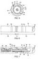
- FIG. 4is a cross-sectional view of the combination of an introducer sheath and working catheter used in the robotic catheter assembly of FIG. 2 , particularly taken along the line 4 - 4 ;
- FIG. 5is a cross-sectional view of the working catheter used in the robotic catheter assembly of FIG. 2 , particularly taken along the line 4 - 4 ;
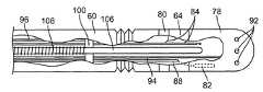
- FIG. 6is a plan view of the distal end of the working catheter used in the robotic catheter assembly of FIG. 2 ;
- FIG. 7is a partially cut-away view of the distal end of the working catheter used in the robotic catheter assembly of FIG. 2 ;
- FIG. 8is a conceptual view of a force sensing assembly used in the robotic catheter assembly of FIG. 2 ;
- FIG. 9illustrates a method of operating the robotic catheter system of FIG. 1 to sense a force applied between endocardial tissue and the distal end of the working catheter illustrated in FIG. 6 ;
- FIG. 10is a plan view of the distal end of another working catheter used in the robotic catheter assembly of FIG. 2 ;
- FIG. 11illustrates a method of operating the robotic catheter system of FIG. 1 to sense a force applied between the inner lining of a stomach and the distal end of the working catheter illustrated in FIG. 10 ;
- FIG. 12is a perspective view of the distal end of still another working catheter used in the robotic catheter assembly of FIG. 2 ;
- FIG. 13is a perspective view of the distal end of yet another working catheter used in the robotic catheter assembly of FIG. 2 .
- proximal and distalrefer to direction close to and away from, respectively, an operator (e.g., surgeon, physician, nurse, technician, etc.) who would insert the medical device into the patient, with the tip-end (i.e., distal end) of the device inserted inside a patient's body first.
- an operatore.g., surgeon, physician, nurse, technician, etc.
- the catheter end inserted inside the patient's bodywould be the distal end of the catheter, while the catheter end left outside the patient's body would be the proximal end of the catheter.
- U.S. patent application Ser. No. 11/678,001(the '001 application), which is commonly assigned with the present application, discloses robotically-navigated interventional systems and methods having the capability to sense force between a distal end of a working instrument (such as a catheter) and the surface of a body cavity or lumen (referred to collectively as a “body space”).
- the robotic systemnot only detects contact between the working instrument and the surface, but also measures the magnitude of the force, also called the load.
- Such systems and methodscan also be used to detect contact with tissue structures.
- the robotic system described in the '001 applicationcomprises a robotic instrument driver that directly interfaces with a coaxial arrangement of an introducer sheath and a guide catheter, and an operator control station for remotely controlling movements of the introducer sheath and guide catheter through the instrument driver.
- a working catheterwhich can be manually operated by a physician, is disposed through the robotic guide catheter (typically via a Touhy valve), which in turn, is disposed through the robotic introducer sheath.
- the instrument drivercomprises two actuation mechanisms (referred to as “splayers”) that tension control wires within the introducer sheath and guide sheath to provide them with steering actuation.
- the instrument drivermay move the splayers relative to each other to provide independent insertion or retraction movements to the introducer sheath and guide catheter along a longitudinal axis.
- the robotic system described in the '001 applicationmeasures a force applied to the distal end of the working catheter using a dithering technique.
- the working catheteris “dithered” with respect to the guide catheter by moving the guide catheter back and forth in a repeated cyclic motion to overcome frictional challenges, normally complicating a measurement of loads at the distal end of the working catheter when in contact with a surface. That is, if a user were to position the working catheter down the lumen of the guide catheter, so that the distal end of the working catheter extends out slightly beyond the distal end of the guide catheter, it may be difficult to accurately sense force applied to the distal end of the working catheter due to the complications of the physical relationship with the associated guide catheter.
- the static coefficient of frictionis applicable, and as such, there are relatively large frictional forces keeping the working catheter in place relative to the guide catheter (no relative movement between the two).
- the dithering motionis used to effectively break loose this frictional coupling.
- the dithering motionis provided by a ditherer that is mechanically coupled to the proximal end of the working catheter extending out from the proximal end of the guide catheter.
- a bellowsis provided on the Touhy valve through which the working catheter is inserted into the guide catheter to facilitate dithering of the working catheter.
- Sensorsare provided on the ditherer for measuring forces applied at the distal end of the working catheter and transmitted through the shaft of the working catheter to the ditherer.
- the dynamic frictionis baselined by measuring the insertion and withdrawal forces generated by the moving working catheter. Thus, any additional force that is measured by the application of external forces to the distal end of the working catheter can be calculated by subtracting the baseline frictional force from the total measured force.
- the specific dithering technique discussed in the '001 applicationprovides an accurate technique for sensing forces applied to the distal end of a manually operated working catheter.
- the embodiment disclosed hereinprovides a dithering technique for sensing forces applied to the distal end of a robotic working catheter (e.g., a robotically steerable catheter having a therapeutic and/or diagnostic function) despite the fact that the proximal end of the working catheter would be affixed to a robotically controlled actuator, such as a splayer.
- the system 10generally comprises an operating table 12 having a movable support-arm assembly 14 , an operator control station 16 located remotely from the operating table 12 , and a robotic catheter assembly 18 mounted to the support-arm assembly 14 above the operating table 12 .
- Exemplary robotic catheter systemsthat may be modified for constructing and using embodiments of the present invention are disclosed in detail in the following U.S. patent applications, which are all expressly incorporated herein by reference in their entirety: U.S. patent application Ser. No. 11/678,001, filed Feb. 22, 2007; U.S. patent application Ser. No. 11/073,363, filed Mar. 4, 2005; U.S. patent application Ser. No.
- the control station 16comprises a user interface 20 that is operatively connected to the robotic catheter assembly 18 .
- a physician or other user 22may interact with the user interface 20 to operate the robotic catheter assembly 18 .
- the user interface 20is connected to the robotic catheter assembly 18 via a cable 24 or the like, thereby providing one or more communication links capable of transferring signals between the control station 16 and the robotic catheter assembly 18 .
- the user interface 20may be located in a geographically remote location and communication is accomplished, at least in part, over a wide area network such as the Internet.
- the user interface 20may also be connected to the robotic catheter assembly 18 via a local area network or even wireless network that is not located at a geographically remote location.
- the control station 16also comprises one or more monitors 26 used to display various aspects of the robotic instrument system 10 .
- monitors 26used to display various aspects of the robotic instrument system 10 .
- an image of the introducer sheath and working cathetermay be displayed in real time on the monitors 26 to provide the physician 22 with the current orientation of the various devices as they are positioned, for example, within a body lumen or region of interest.
- the control station 16further comprises a computer 28 , which may comprise a personal computer or other type of computer work station for performing the data processing operations disclosed herein.
- the support-arm assembly 14is configured for movably supporting the robotic catheter assembly 18 above the operating table 12 to provide convenient access to the desired portions of the patient (not shown) and provide a means to lock the catheter assembly 18 into position subsequent to the preferred placement.
- the support-arm assembly 14comprises a series of rigid links 30 coupled by electronically braked joints 32 , which prevent joint motion when unpowered, and allow joint motion when energized by the control station 16 .
- the rigid links 30may be coupled by more conventional mechanically lockable joints, which may be locked and unlocked manually using, for example, locking pins, screws, or clamps.
- the rigid links 30preferably comprise a light but strong material, such as high-gage aluminum, shaped to withstand the stresses and strains associated with precisely maintaining three-dimensional position of the weight of the catheter assembly 18 .
- the catheter assembly 18comprises a robotic instrument driver 34 , a robotic introducer sheath 36 and a robotic working catheter 38 mounted to the instrument driver 34 in a coaxial relationship, and a dithering force sensing assembly 40 mounted to the instrument driver 16 in mechanical communication with the proximal end of the working catheter 38 .
- the robotic catheter assembly 18may also include a drape (not shown) that covers the instrument driver 34 .
- the introducer sheath 36comprises an elongated sheath body 42 having a proximal end 44 and a distal end 46 , and a working lumen 48 extending through the sheath body 42 between the proximal and distal ends 44 , 46 .
- the geometry and size of the working lumen 48will be selected in accordance with the cross-sectional geometry and size of the working catheter 38 .
- the sheath body 42may be composed of a low-friction inner layer 50 (e.g., a coating of silicone or polytetrafluoroethylene) to provide a low-friction surface to accommodate movement of the working catheter 38 within the working lumen 48 , a stiffening layer 52 (e.g., a braided material or a metallic spine) disposed over the outer surface of the inner layer 50 , and an outer layer 54 disposed over the outer surface of the stiffening layer 52 .
- a low-friction inner layer 50e.g., a coating of silicone or polytetrafluoroethylene
- a stiffening layer 52e.g., a braided material or a metallic spine
- the introducer sheath 36further comprises a control element in the form of steering wire 56 extending through a steering lumen 58 disposed within the wall of the sheath body 42 , and in particular, the outer layer 54 .
- the distal end of the steering wire 56is suitably mounted to an anchoring element (not shown) at the distal end 46 of the sheath body 42 , and the proximal end of the steering wire 56 extends out the proximal end 44 of the sheath body 42 , so that it can be suitably coupled to instrument driver 34 , as discussed in further detail below.
- the proximal end 44 of the sheath body 42includes an aperture (not shown) through which the steering wire 56 exits to the instrument driver 34 .
- the distal end 44 of the sheath body 42can be alternately deflected and straightened via actuation of the steering wire 56 .
- the working catheter 38may include any number of types of catheters, but in the illustrated embodiment, takes the form of an electrophysiology/ablation catheter.
- the forces sensed at the distal end of the cathetercan be conveyed to an ablation generator (not shown).
- the ablation generatormay be operated as long as the sensed force is with the range required to provide effective treatment.
- the ablation generatormay automatically cease conveying ablation energy to the catheter if the sensed force falls outside of this requirement range.
- the ablation generatormay automatically compute and set and particular ablation power, ablation time, temperature, etc., as a function of the sensed force.
- the working catheter 38may alternatively or additionally carry other types of operative elements, such as a tool or device (also called end effectors) (e.g. an imaging device or cutting tool disposed on the distal end of the catheter 38 ).
- a tool or devicealso called end effectors
- the working catheter 38may take the form of an endoscopic surgical instrument or other elongated medical instrument. If not used intravascularly, the working catheter 38 can be rigid or semi-rigid.
- the working catheter 38passes through the lumen 48 of the introducer sheath 36 , and is thus, moveable relative thereto. As shown in FIGS. 2 and 3 , the working catheter 38 projects distally with respect to the distal end 44 of the sheath body 42 . Of course, the working catheter 38 may be withdrawn proximally such that its distal end is substantially flush with the distal end 44 of the sheath body 42 , or withdrawn proximally even further such that its distal end is disposed within the distal end 44 of the sheath body 42 .
- the working catheter 38may be movably positioned within the working lumen 48 of the introducer sheath 36 to enable relative insertion of the two devices, relative rotation, or “roll” of the two devices, and relative steering or bending of the two devices relative to each other, particularly when the distal end of the working catheter 38 is inserted beyond the distal tip of the introducer sheath 36 .
- the working catheter 38comprises an elongated catheter body 60 having a proximal end 62 and a distal end 64 .
- the catheter body 60can be divided into three sections: a proximal shaft section 66 , a distal section 68 , and an axially flexible section 70 between the proximal and distal sections 66 , 68 . As best shown in FIG.
- the proximal section 66 of the catheter body 60may be composed of a low-friction inner lubricious layer 72 , a stiffening layer 74 (e.g., a braided material or a metallic spine) disposed over the outer surface of the inner layer 72 , and an outer layer 76 disposed over the outer surface of the stiffening layer 74 . Because the proximal section 66 is structurally reinforced by inclusion of the stiffening layer 74 , torque transmission and insertability of the catheter 38 is enhanced, while also providing enough cantilever bendability to facilitate access to remote tissue locations, such as the chambers of the heart. As best shown in FIG. 5 , the distal section 68 of the catheter body 60 is composed of the inner lubricious layer 72 and the outer layer 76 , and is more laterally flexible than the proximal section 66 due to the lack of a stiffening layer.
- a stiffening layer 74e.g., a braided material or a metallic spine
- the axially flexible section 70 of the catheter body 60which in the illustrated embodiment takes the form of a bellows, can axially elongate and contract in much the same way as an accordion, thereby allowing the distal section 68 to be axially displaced relative to the proximal section 66 in response to the application of an axial force to the distal section 68 .
- this featureallows the distal end 64 of the catheter body 60 to be axially dithered back and forth, while also facilitating the transfer of axial forces externally applied to the distal end 64 of the catheter body 60 to the force sensing assembly 40 .
- the working catheter 38takes the form of an electrophysiology/ablation catheter, and thus, comprises an ablation electrode, and in particular, a tip electrode 78 , and an electrophysiology mapping electrode, and in particular, a ring electrode 80 mounted around the distal end 64 of the catheter body 60 proximal to the tip electrode 78 .
- the electrodes 78 , 80may be composed of a suitably electrically conductive material, such as stainless steel or platinum.
- the cathetermay further comprise a temperature sensor 82 (shown in phantom), such as a thermocouple or thermistor, suitably mounted within the tip electrode 78 .
- the catheter 38comprises electrical leads 84 extending through a wire lumen 86 (shown in FIGS. 4 and 5 ) within the catheter body 60 , with the distal ends of the electrical leads 84 respectively terminating at the tip electrode 78 and ring electrode 80 , and the proximal ends of the electrical leads 84 terminating in the instrument driver 34 (described in further detail below).
- the catheter 38also comprises an electrical lead 88 extending through a wire lumen 90 (shown in FIGS. 4 and 5 ) within the catheter body 60 , with the distal end of the electrical lead 88 terminating at the temperature sensor 82 , and the proximal end of the electrical lead 88 terminating in the instrument driver 34 (described in further detail below).
- the tip electrode 78optionally includes fluid irrigation ports 92 through which a fluid, such as saline, can flow.
- the catheter 38comprises a fluid lumen 94 extending through the catheter body 60 , with the distal end of the fluid lumen 94 terminating within the tip electrode 78 in fluid communication with the irrigation ports 92 , and the proximal end of the fluid lumen 94 terminating in the instrument driver 34 (described in further detail below).
- the catheter 38further comprises a plurality of control elements (in this case, four) in the form of steering wires 96 extending through respective steering lumens 98 disposed within the wall of the catheter body 60 , and in particular, the outer layer 76 of the proximal section 66 .
- the catheter 38further comprises an anchoring element 100 , and in particular an anchoring ring, embedded within the outer layer 76 of the proximal section 66 of the catheter body 60 .
- the distal ends of the steering wires 96(only one shown in FIG.
- the proximal end of the steering wiresextend out the proximal end 62 of the catheter body 60 , so that it can be suitably coupled to instrument driver 34 (described in further detail below).
- the proximal end 62 of the catheter body 60includes apertures (not shown) through which the respective steering wires 96 exit to the instrument driver 34 .
- the distal end 64 of catheter body 60can be alternately deflected in four different directions and straightened via actuation of the steering wires 96 .
- the catheter 38further comprises a central lumen 104 extending within the catheter body 60 between the proximal and distal ends 62 , 64 of the catheter body 60 , and a push-pull rod 106 slidably disposed within the central lumen 104 .
- the distal end of the push-pull rod 106is affixed to the catheter body 60 at a point distal to the axially flexible section 70 , and in particular, to the distal end 64 of the catheter body 60 (e.g., by soldering it to the inner surface of the tip electrode 78 ).
- the proximal end of the push-pull rod 106extends out from the proximal end 62 of the catheter body 60 , so that it can be suitably coupled to the force sensing assembly 40 , as will be described in further detail below.
- the push-pull rod 106may also function as a “safety wire” to protect the patient if the distal shaft section 68 of the catheter body 60 .
- the push-pull rod 106may also be used as an electrical lead 84 in lieu of the electrical leads 84 discussed above.
- the push-pull rod 106preferably includes an electrically conductive core and an electrically insulative coating disposed over the core.
- the catheter 38optionally comprises a coil 108 affixed around the push-pull rod 106 .
- the coil 108may be composed of a material or be coated with a material that has a lower coefficient of friction than that of the push-pull rod 106 .
- the coil 108may be coated with polytetrafluoroethylene. In this manner, friction between the push-pull rod 106 and the lumen 104 , which may otherwise be excessive if too much surface area of the push-pull rod 106 is in contact with the central lumen 104 when the proximal shaft section 66 is articulated in response to actuation of one of the steering wires 96 , is reduced.
- the coil 108also facilitates the centering of the push-pull rod 106 within the lumen 104 .
- the instrument driver 34provides robotic steering actuation, as well as robotic insertion and retraction actuation, to the introducer sheath 36 and working catheter 38 in accordance with control signals transmitted from the control station 16 (shown in FIG. 1 ).
- the instrument driver 34comprises a housing 110 that contains motors (not shown), an introducer sheath adapter 112 (“sprayer”) to which the proximal end 44 of the sheath body 42 is operably mounted, and a working catheter adapter 114 (“splayer”) to which the proximal end 62 of the catheter body 60 is operably mounted.
- the respective adapters 112 , 114are mechanically interfaced to the housing 110 in such a manner that they may be axially displaced relative to each other via operation of the motors, thereby effecting insertion or retraction movements of the respective introducer sheath 36 and working catheter 38 relative to each other, and thus, relative to the operating table 12 (shown in FIG. 1 ).
- Each of the adapters 112 , 114also comprise one or more rotating spools or drums 116 that can selectively tension or release the steering wires 56 , 96 disposed within the respective sheath body 42 and catheter body 60 , thereby effecting deflection of the distal ends 46 , 64 of the sheath and catheter bodies 42 , 60 .
- Each of the adapters 112 , 114may optionally be capable of rotating or rolling the sheath body 42 and catheter body 60 relative to each other. If the working catheter 38 alternatively or additionally includes an operative element requiring mechanical actuation, the catheter adapter 114 may include additional spools (not shown) for tensioning control elements (not shown) coupled to the operative element.
- RFradio frequency
- electrophysiology mapping equipmentcan be coupled to the electrical connector 118 to allow the transmission of RF energy and temperature signals between the RF generator and the tip electrode 78 and temperature sensor 82 (shown in FIGS. 6 and 7 ), and to allow the transmission of signals between the ring electrode 80 (shown in FIGS. 6 and 7 ) and the electrophysiology mapping equipment.
- the proximal end of the fluid lumen 94exits from the proximal end 62 of the catheter body 60 into the catheter adapter 114 , which then exit the catheter adapter 114 and terminate in a luer connector 120 .
- a fluid pump(not shown) can be coupled to the luer connector 120 to allow the conveyance of the fluid between the pump out through the fluid delivery ports 92 on the tip electrode 78 (shown in FIGS. 6 and 7 ).
- the proximal end of the push-pull rod 106exits from the proximal end 62 of the catheter body 60 into the catheter adapter 114 , which then exits the catheter adapter 114 and terminates in the force sensing assembly 40 .
- the force sensing assembly 40comprises a mechanical ditherer 122 and a force sensor 124 . Although only one force sensor 124 is shown and described, multiple force sensors can be used.
- the ditherer 122is mounted to the housing 110 of the instrument driver 34 proximal to the catheter adapter 114 .
- the ditherer 122is coupled to the proximal end of the push-pull rod 106 , so that the push-pull rod 106 can be axially dithered back and forth, thereby axially dithering the distal end 64 of the catheter body 60 back and forth.
- the length or stroke of the ditheringmay be adjusted depending on the nature of the procedure, but generally is less than a few millimeters. In some embodiments, the stroke of the dithering may be less than about 1.5 mm.
- the frequency of the ditheringmay be several cycles per second, e.g., 10-20 Hz, thereby ensuring that any static friction is broken.
- the force sensor 124may be disposed at various locations, including at the distal end 64 of the catheter body 60 .
- the force sensor 124is disposed on the ditherer 122 .
- the force sensor 124is used to detect the force or load that is being applied to the distal end 64 of the catheter body 60 by detecting the force or load that is applied at the proximal end of the push-pull rod 106 .
- the force sensor 124is able to sense the insertion and withdrawal forces applied to the distal end 64 of the catheter body 60 via the ditherer 122 .
- the force sensing assembly 40may optionally comprise a strain-gage (not shown) located at the distal end of the push-pull rod 106 for sensing lateral or deflection forces applied to the distal end 64 of the catheter body 60 .
- the catheter 38may also comprise a sensor, e.g., an optical or capacitive sensor (not shown), located at the distal end 64 of the catheter body 60 to confirm that the distal end 64 is dithering back and forth.
- FIG. 8one embodiment of a force sensing assembly 40 used for measuring a force at the distal end 64 of the catheter body 60 will be described.
- the distal end 64 of the catheter body 60dithers with respect to the introducer sheath 36 .
- the ditherer 122will drive the push-pull rod 106 through the force sensor 124 , which will measure the direct force needed to insert and retract the push-pull rod 106 within the lumen 104 of the working catheter 38 .
- the ditherer 122is mechanically grounded (via a mechanical linkage 126 ) to the proximal end 62 of the catheter body 60 , and is thus, stationary relative to the introducer sheath 36 .
- the force sensor 124 and push-pull rod 106move together relative to the proximal end 62 of the catheter body 60 .
- the force sensing assembly 40is in operable communication with control station 16 via the communication link 24 for data processing.
- condition electronics 128receives the electrical signals generated by the force sensor 124 , and the computer 28 processes the conditioned electrical signals.
- a representation of the axial force applied at the distal end 64 of the catheter body 60can be displayed on the monitor 26 .
- the force profiles or waveforms obtained from the force signalscan be used to accurately estimate the contact forces at the distal end 64 of the catheter body 60 .
- the computer 28obtains a baseline force measurement by receiving signals from force sensor 124 when the push-pull rod 106 is dithered back and forth and while an external axial force is not applied to the distal end 64 of the catheter body 60 .
- the computer 28may then later obtain a total force measurement by receiving signals from the force sensor 124 when the push-pull rod 106 is dithered back and forth and an external axial force is applied to the distal end 64 of the catheter body 60 (e.g., when the distal tip of the catheter 38 contacts tissue).
- the computer 28then computes the external axial force applied to the distal end 64 of the catheter body 60 by subtracting the baseline force measurement from the total force measurement.
- the total force measurementmay capture signal induced by physiological cycles, such as the respiratory cycle and heart cycle.
- the force sensing assembly 40may comprise a filter (not shown) for separating the physiological variations within the total force measurement.
- the introducer sheath 36With the working catheter 38 retracted therein, is intravascularly introduced through a puncture within the patient's body and robotically advanced through the vasculature of the patient to a target site, such as a chamber of the heart, as illustrated in FIG. 9 a .
- a target sitesuch as a chamber of the heart
- the introducer sheath 36is transeptally introduced into the left atrium of the heart.
- the working catheter 38is then robotically advanced out of the introducer sheath 36 , as shown in FIG. 9 b .
- the distal end of the working catheter 38is then axially dithered back and forth relative to the proximal end of the working catheter 38 , as shown by the arrows in FIG. 9 c .
- thisis accomplished by operating the ditherer 122 to axially dither the push-pull rod 106 back and forth, thereby dithering the distal end of the working catheter 38 back and forth via operation of the bellows 70 .
- the distal end of the working catheter 38is axially dithered back and forth when an external axial force is not presently applied between the tissue and the distal end of the working catheter 38 , and measuring the force at the force sensor 124 to obtain a baseline force measurement. While the distal end of the working catheter 38 is dithered, it is then robotically moved within at least one-degree of freedom (e.g., by deflecting the distal end of the working catheter 38 ), thereby placing it in contact with tissue, as shown in FIG. 9 d . Because the force at the force sensor 124 is continuously measured, the total force measurement will be obtained as the distal end of the working catheter 38 is placed into contact with the tissue. The axial force applied between the tissue and the distal end of the working catheter 38 can then be computed (in this case, by the computer 28 ) by subtracting the baseline force measurement from the total force measurement.
- the operative elements at the distal end of the working catheter 38can then be operated to perform the therapeutic and/or diagnostic function (in this case, tissue ablation and/or mapping) on the patient.
- the distal end of the working catheter 38can be moved to a different region on the tissue.
- the axial force applied between the tissue and the distal end of the working catheter 38can again then be measured and the operative elements at the distal end of the working catheter 38 operated to again perform the therapeutic and/or diagnostic function.
- FIG. 10illustrates a working catheter 150 having an elongated catheter body 152 , a pair of grasper arms 154 affixed to the distal end of the catheter body 152 , and a cable 156 extending through the catheter body 152 and coupled to the grasper arms 154 .
- the grasper arms 154can be spring-loaded to open relative to each other, in which case, the cable 156 can be pulled to close the arms 154 relative to each other.
- the working catheter 150includes an axially flexible section 158 , and a push-pull rod 160 slidably disposed within a central lumen 162 extending through the catheter body 152 .
- the distal end of the push-pull rod 160is affixed to the catheter body 152 at a point distal to the axially flexible section 158 , and in particular, to the distal end of the catheter body 150 , and a proximal end that extends out from the proximal end of the catheter body 152 , so that it can be suitably coupled to the force sensing assembly 40 in the manner discussed above.
- the catheter 150optionally comprises a centering coil 162 affixed around the push-pull rod 160 .
- the force sensing mechanism disclosed hereincan be used to perform medical procedures in anatomical regions other than the heart.
- the working catheter 150can be used to perform a surgical procedure within the cavity of the stomach 170 while sensing the force between the grasper arms 154 and the wall of the stomach to prevent perforation of the inner lining of the stomach.
- a working catheter 200is similar to the working catheter 38 , with the exception that instead of an axially flexible section (e.g., an bellows), the working catheter 200 includes an axially translatable section 70 that has a seal 202 suitably mounted to the distal end of the proximal shaft section 66 .
- the seal 202includes an annular aperture 204 through which the distal shaft section 68 is disposed. The diameter of the aperture 204 is equal to or less than the outer diameter of the distal shaft section 68 .
- the distal shaft section 68is slidably disposed within the proximal shaft section 66 via the seal 202 , which prevents bodily fluids, such as blood, from entering the working catheter 200 via the interface between the proximal and distal shaft sections 66 , 68 .
- the distal end of the push-pull rod 106is affixed to the distal shaft section 68 , and thus, is displaced with the distal shaft section 68 in the manner and with the result described above with respect to the working catheter 38 .
- the seal 200may be composed of a suitable material, such as rubber, to allow the proximal and distal shaft sections 66 , 68 to easily slide relative to the each other while maintaining a good seal therebetween.
- the proximal end of the distal shaft section 68preferably includes an annular flange 206 that abuts the seal 202 during the farthest extent of distal shaft section 68 , thereby preventing the distal shaft section 68 from disengaging from the proximal shaft section 66 .
- the seal 202is suitably mounted to the proximal end of the distal shaft section 68 , in which case, the proximal shaft section 66 will be slidably disposed within the distal shaft section 68 via the seal 202 .
- the working catheter 200includes a pair of seals 202 —one seal 202 ( 1 ) mounted to the distal end of the proximal shaft section 66 , and another seal 202 ( 2 ) mounted within the proximal shaft section 66 proximal to the first seal 202 ( 1 ).
- Each of the seals 202includes an annular aperture 204 through which the distal shaft section 68 is disposed.
- the seals 202provide suitable bearing surfaces that maintain axial alignment of the distal shaft section 68 within the proximal shaft section 66 .
- the distal end of the fluid lumen 94 extending through the catheter body 60terminates in an aperture 208 within the proximal seal 202 ( 2 ).
- fluidcan be conveyed into a chamber 210 formed between the seals 202 , thereby creating a positive pressure therein.
- any bodily fluids, such as blood, that would otherwise leak through the distal seal 202 ( 1 )is prevented from entering the working catheter 200 due to the positive pressure.
- apertures 212are formed in the distal shaft section 68 through which the positively pressurized fluid can be conveyed to the irrigation ports 92 on the electrode 78 to provide the irrigation function described above.
Landscapes
- Health & Medical Sciences (AREA)
- Life Sciences & Earth Sciences (AREA)
- Surgery (AREA)
- General Health & Medical Sciences (AREA)
- Engineering & Computer Science (AREA)
- Veterinary Medicine (AREA)
- Biomedical Technology (AREA)
- Heart & Thoracic Surgery (AREA)
- Public Health (AREA)
- Animal Behavior & Ethology (AREA)
- Medical Informatics (AREA)
- Molecular Biology (AREA)
- Biophysics (AREA)
- Physics & Mathematics (AREA)
- Pathology (AREA)
- Ophthalmology & Optometry (AREA)
- Nuclear Medicine, Radiotherapy & Molecular Imaging (AREA)
- Hematology (AREA)
- Anesthesiology (AREA)
- Pulmonology (AREA)
- Media Introduction/Drainage Providing Device (AREA)
Abstract
Description
Claims (14)
Priority Applications (3)
| Application Number | Priority Date | Filing Date | Title |
|---|---|---|---|
| US12/269,684US8083691B2 (en) | 2008-11-12 | 2008-11-12 | Apparatus and method for sensing force |
| US12/641,145US8372019B2 (en) | 2008-11-12 | 2009-12-17 | Apparatus and method for sensing force on a robotically controlled medical instrument |
| US13/756,239US9480820B2 (en) | 2008-11-12 | 2013-01-31 | Apparatus and method for sensing force on a robotically controlled medical instrument |
Applications Claiming Priority (1)
| Application Number | Priority Date | Filing Date | Title |
|---|---|---|---|
| US12/269,684US8083691B2 (en) | 2008-11-12 | 2008-11-12 | Apparatus and method for sensing force |
Related Child Applications (2)
| Application Number | Title | Priority Date | Filing Date |
|---|---|---|---|
| US12/641,145Continuation-In-PartUS8372019B2 (en) | 2008-11-12 | 2009-12-17 | Apparatus and method for sensing force on a robotically controlled medical instrument |
| US12/641,145DivisionUS8372019B2 (en) | 2008-11-12 | 2009-12-17 | Apparatus and method for sensing force on a robotically controlled medical instrument |
Publications (2)
| Publication Number | Publication Date |
|---|---|
| US20100121138A1 US20100121138A1 (en) | 2010-05-13 |
| US8083691B2true US8083691B2 (en) | 2011-12-27 |
Family
ID=42165838
Family Applications (3)
| Application Number | Title | Priority Date | Filing Date |
|---|---|---|---|
| US12/269,684Active2030-02-19US8083691B2 (en) | 2008-11-12 | 2008-11-12 | Apparatus and method for sensing force |
| US12/641,145Active2028-12-25US8372019B2 (en) | 2008-11-12 | 2009-12-17 | Apparatus and method for sensing force on a robotically controlled medical instrument |
| US13/756,239Active2031-06-07US9480820B2 (en) | 2008-11-12 | 2013-01-31 | Apparatus and method for sensing force on a robotically controlled medical instrument |
Family Applications After (2)
| Application Number | Title | Priority Date | Filing Date |
|---|---|---|---|
| US12/641,145Active2028-12-25US8372019B2 (en) | 2008-11-12 | 2009-12-17 | Apparatus and method for sensing force on a robotically controlled medical instrument |
| US13/756,239Active2031-06-07US9480820B2 (en) | 2008-11-12 | 2013-01-31 | Apparatus and method for sensing force on a robotically controlled medical instrument |
Country Status (1)
| Country | Link |
|---|---|
| US (3) | US8083691B2 (en) |
Cited By (61)
| Publication number | Priority date | Publication date | Assignee | Title |
|---|---|---|---|---|
| US20110153253A1 (en)* | 2009-12-23 | 2011-06-23 | Assaf Govari | Calibration system for a pressure-sensitive catheter |
| US20110153252A1 (en)* | 2009-12-23 | 2011-06-23 | Assaf Govari | Actuator-based calibration system for a pressure-sensitive catheter |
| US20120150075A1 (en)* | 2010-12-10 | 2012-06-14 | Doron Moshe Ludwin | System and method for detection of metal disturbance based on mutual inductance measurement |
| US8374670B2 (en) | 2010-01-22 | 2013-02-12 | Biosense Webster, Inc. | Catheter having a force sensing distal tip |
| US8380276B2 (en) | 2010-08-16 | 2013-02-19 | Biosense Webster, Inc. | Catheter with thin film pressure sensing distal tip |
| US8437832B2 (en) | 2008-06-06 | 2013-05-07 | Biosense Webster, Inc. | Catheter with bendable tip |
| US8475450B2 (en) | 2008-12-30 | 2013-07-02 | Biosense Webster, Inc. | Dual-purpose lasso catheter with irrigation |
| US8535308B2 (en) | 2007-10-08 | 2013-09-17 | Biosense Webster (Israel), Ltd. | High-sensitivity pressure-sensing probe |
| US8600472B2 (en) | 2008-12-30 | 2013-12-03 | Biosense Webster (Israel), Ltd. | Dual-purpose lasso catheter with irrigation using circumferentially arranged ring bump electrodes |
| US8608735B2 (en) | 2009-12-30 | 2013-12-17 | Biosense Webster (Israel) Ltd. | Catheter with arcuate end section |
| US8731859B2 (en) | 2010-10-07 | 2014-05-20 | Biosense Webster (Israel) Ltd. | Calibration system for a force-sensing catheter |
| US20140148673A1 (en)* | 2012-11-28 | 2014-05-29 | Hansen Medical, Inc. | Method of anchoring pullwire directly articulatable region in catheter |
| US8784413B2 (en) | 2007-10-08 | 2014-07-22 | Biosense Webster (Israel) Ltd. | Catheter with pressure sensing |
| US8798952B2 (en) | 2010-06-10 | 2014-08-05 | Biosense Webster (Israel) Ltd. | Weight-based calibration system for a pressure sensitive catheter |
| US8852130B2 (en) | 2009-12-28 | 2014-10-07 | Biosense Webster (Israel), Ltd. | Catheter with strain gauge sensor |
| US8920415B2 (en) | 2009-12-16 | 2014-12-30 | Biosense Webster (Israel) Ltd. | Catheter with helical electrode |
| US20150073245A1 (en)* | 2008-12-31 | 2015-03-12 | St. Jude Medical, Atrial Fibrillation Division, Inc. | System and method for measuring force and torque applied to a catheter electrode tip |
| US8979772B2 (en) | 2010-11-03 | 2015-03-17 | Biosense Webster (Israel), Ltd. | Zero-drift detection and correction in contact force measurements |
| US9101734B2 (en) | 2008-09-09 | 2015-08-11 | Biosense Webster, Inc. | Force-sensing catheter with bonded center strut |
| US9101396B2 (en) | 2010-06-30 | 2015-08-11 | Biosense Webster (Israel) Ltd. | Pressure sensing for a multi-arm catheter |
| US9211094B2 (en) | 2010-12-10 | 2015-12-15 | Biosense Webster (Israel), Ltd. | System and method for detection of metal disturbance based on contact force measurement |
| US9220433B2 (en) | 2011-06-30 | 2015-12-29 | Biosense Webster (Israel), Ltd. | Catheter with variable arcuate distal section |
| US9326700B2 (en) | 2008-12-23 | 2016-05-03 | Biosense Webster (Israel) Ltd. | Catheter display showing tip angle and pressure |
| US9662169B2 (en) | 2011-07-30 | 2017-05-30 | Biosense Webster (Israel) Ltd. | Catheter with flow balancing valve |
| US9687289B2 (en) | 2012-01-04 | 2017-06-27 | Biosense Webster (Israel) Ltd. | Contact assessment based on phase measurement |
| US9898937B2 (en) | 2012-09-28 | 2018-02-20 | Applied Medical Resources Corporation | Surgical training model for laparoscopic procedures |
| US9922579B2 (en) | 2013-06-18 | 2018-03-20 | Applied Medical Resources Corporation | Gallbladder model |
| US9940849B2 (en) | 2013-03-01 | 2018-04-10 | Applied Medical Resources Corporation | Advanced surgical simulation constructions and methods |
| US9959786B2 (en) | 2012-09-27 | 2018-05-01 | Applied Medical Resources Corporation | Surgical training model for laparoscopic procedures |
| US9999475B2 (en) | 2013-02-15 | 2018-06-19 | Intuitive Surgical Operations, Inc. | Actuated cannula seal |
| US10081727B2 (en) | 2015-05-14 | 2018-09-25 | Applied Medical Resources Corporation | Synthetic tissue structures for electrosurgical training and simulation |
| US10121391B2 (en) | 2012-09-27 | 2018-11-06 | Applied Medical Resources Corporation | Surgical training model for laparoscopic procedures |
| US10140889B2 (en) | 2013-05-15 | 2018-11-27 | Applied Medical Resources Corporation | Hernia model |
| US10198966B2 (en) | 2013-07-24 | 2019-02-05 | Applied Medical Resources Corporation | Advanced first entry model for surgical simulation |
| US10198965B2 (en) | 2012-08-03 | 2019-02-05 | Applied Medical Resources Corporation | Simulated stapling and energy based ligation for surgical training |
| US10223936B2 (en) | 2015-06-09 | 2019-03-05 | Applied Medical Resources Corporation | Hysterectomy model |
| US10307205B2 (en) | 2010-12-10 | 2019-06-04 | Biosense Webster (Israel) Ltd. | System and method for detection of metal disturbance based on orthogonal field components |
| US10332425B2 (en) | 2015-07-16 | 2019-06-25 | Applied Medical Resources Corporation | Simulated dissectible tissue |
| US10327808B2 (en) | 2012-02-15 | 2019-06-25 | Intuitive Surgical Operations, Inc. | Low friction cannula seals for minimally invasive robotic surgery |
| US10350423B2 (en) | 2016-02-04 | 2019-07-16 | Cardiac Pacemakers, Inc. | Delivery system with force sensor for leadless cardiac device |
| US10350390B2 (en) | 2011-01-20 | 2019-07-16 | Auris Health, Inc. | System and method for endoluminal and translumenal therapy |
| US10354556B2 (en) | 2015-02-19 | 2019-07-16 | Applied Medical Resources Corporation | Simulated tissue structures and methods |
| US10395559B2 (en) | 2012-09-28 | 2019-08-27 | Applied Medical Resources Corporation | Surgical training model for transluminal laparoscopic procedures |
| US10490105B2 (en) | 2015-07-22 | 2019-11-26 | Applied Medical Resources Corporation | Appendectomy model |
| US10535281B2 (en) | 2012-09-26 | 2020-01-14 | Applied Medical Resources Corporation | Surgical training model for laparoscopic procedures |
| US10657845B2 (en) | 2013-07-24 | 2020-05-19 | Applied Medical Resources Corporation | First entry model |
| US10667720B2 (en) | 2011-07-29 | 2020-06-02 | Auris Health, Inc. | Apparatus and methods for fiber integration and registration |
| US10679520B2 (en) | 2012-09-27 | 2020-06-09 | Applied Medical Resources Corporation | Surgical training model for laparoscopic procedures |
| US10688278B2 (en) | 2009-11-30 | 2020-06-23 | Biosense Webster (Israel), Ltd. | Catheter with pressure measuring tip |
| US10706743B2 (en) | 2015-11-20 | 2020-07-07 | Applied Medical Resources Corporation | Simulated dissectible tissue |
| US10720084B2 (en) | 2015-10-02 | 2020-07-21 | Applied Medical Resources Corporation | Hysterectomy model |
| US10796606B2 (en) | 2014-03-26 | 2020-10-06 | Applied Medical Resources Corporation | Simulated dissectible tissue |
| US10818201B2 (en) | 2014-11-13 | 2020-10-27 | Applied Medical Resources Corporation | Simulated tissue models and methods |
| US10847057B2 (en) | 2017-02-23 | 2020-11-24 | Applied Medical Resources Corporation | Synthetic tissue structures for electrosurgical training and simulation |
| US10854112B2 (en) | 2010-10-01 | 2020-12-01 | Applied Medical Resources Corporation | Portable laparoscopic trainer |
| US11030922B2 (en) | 2017-02-14 | 2021-06-08 | Applied Medical Resources Corporation | Laparoscopic training system |
| US11120708B2 (en) | 2016-06-27 | 2021-09-14 | Applied Medical Resources Corporation | Simulated abdominal wall |
| US11158212B2 (en) | 2011-10-21 | 2021-10-26 | Applied Medical Resources Corporation | Simulated tissue structure for surgical training |
| US11403968B2 (en) | 2011-12-20 | 2022-08-02 | Applied Medical Resources Corporation | Advanced surgical simulation |
| US11628022B2 (en) | 2017-09-05 | 2023-04-18 | Covidien Lp | Collision handling algorithms for robotic surgical systems |
| US12383274B1 (en)* | 2024-04-12 | 2025-08-12 | Cilag Gmbh International | Shaft deflection detection system for a surgical instrument |
Families Citing this family (66)
| Publication number | Priority date | Publication date | Assignee | Title |
|---|---|---|---|---|
| US8918212B2 (en) | 2009-06-24 | 2014-12-23 | Intuitive Surgical Operations, Inc. | Arm with a combined shape and force sensor |
| WO2011137336A1 (en)* | 2010-04-30 | 2011-11-03 | President And Fellows Of Harvard College | Motion compensating catheter device |
| JP6318088B2 (en)* | 2011-07-26 | 2018-04-25 | アンフォラ メディカル, インコーポレイテッド | Apparatus and method for modulating pelvic nerve tissue |
| US10743932B2 (en) | 2011-07-28 | 2020-08-18 | Biosense Webster (Israel) Ltd. | Integrated ablation system using catheter with multiple irrigation lumens |
| US10791950B2 (en) | 2011-09-30 | 2020-10-06 | Biosense Webster (Israel) Ltd. | In-vivo calibration of contact force-sensing catheters using auto zero zones |
| US9387048B2 (en) | 2011-10-14 | 2016-07-12 | Intuitive Surgical Operations, Inc. | Catheter sensor systems |
| US10238837B2 (en) | 2011-10-14 | 2019-03-26 | Intuitive Surgical Operations, Inc. | Catheters with control modes for interchangeable probes |
| US9452276B2 (en) | 2011-10-14 | 2016-09-27 | Intuitive Surgical Operations, Inc. | Catheter with removable vision probe |
| US20130303944A1 (en) | 2012-05-14 | 2013-11-14 | Intuitive Surgical Operations, Inc. | Off-axis electromagnetic sensor |
| US9956042B2 (en) | 2012-01-13 | 2018-05-01 | Vanderbilt University | Systems and methods for robot-assisted transurethral exploration and intervention |
| JP5940864B2 (en)* | 2012-04-12 | 2016-06-29 | カール シュトルツ ゲゼルシャフト ミット ベシュレンクテル ハフツング ウント コンパニー コマンディートゲゼルシャフト | Medical manipulator |
| WO2013158983A1 (en) | 2012-04-20 | 2013-10-24 | Vanderbilt University | Robotic device for establishing access channel |
| US9539726B2 (en)* | 2012-04-20 | 2017-01-10 | Vanderbilt University | Systems and methods for safe compliant insertion and hybrid force/motion telemanipulation of continuum robots |
| US9687303B2 (en) | 2012-04-20 | 2017-06-27 | Vanderbilt University | Dexterous wrists for surgical intervention |
| US10213130B2 (en) | 2012-07-12 | 2019-02-26 | Siemens Healthcare Gmbh | Compressable catheter tip with image-based force sensing |
| EP2737922B1 (en)* | 2012-11-28 | 2016-05-04 | Hansen Medical, Inc. | Catheter having unirail pullwire architecture |
| CN103083781B (en)* | 2013-01-10 | 2014-08-06 | 南京航空航天大学 | Modularized initiative bent intervention catheter and motion method thereof |
| US9566414B2 (en) | 2013-03-13 | 2017-02-14 | Hansen Medical, Inc. | Integrated catheter and guide wire controller |
| US20140276394A1 (en) | 2013-03-15 | 2014-09-18 | Hansen Medical, Inc. | Input device for controlling a catheter |
| US9283046B2 (en) | 2013-03-15 | 2016-03-15 | Hansen Medical, Inc. | User interface for active drive apparatus with finite range of motion |
| US10849702B2 (en) | 2013-03-15 | 2020-12-01 | Auris Health, Inc. | User input devices for controlling manipulation of guidewires and catheters |
| US9498291B2 (en) | 2013-03-15 | 2016-11-22 | Hansen Medical, Inc. | Touch-free catheter user interface controller |
| US11020016B2 (en) | 2013-05-30 | 2021-06-01 | Auris Health, Inc. | System and method for displaying anatomy and devices on a movable display |
| EP3243476B1 (en) | 2014-03-24 | 2019-11-06 | Auris Health, Inc. | Systems and devices for catheter driving instinctiveness |
| JP2017516620A (en) | 2014-05-23 | 2017-06-22 | アンフォラ メディカル, インコーポレイテッド | Methods and devices for treatment of pelvic conditions |
| EP3200718A4 (en) | 2014-09-30 | 2018-04-25 | Auris Surgical Robotics, Inc | Configurable robotic surgical system with virtual rail and flexible endoscope |
| HK1244652A1 (en)* | 2014-10-20 | 2018-08-17 | Research Development International Corporation | Steerable micro-endoscope |
| US10314463B2 (en) | 2014-10-24 | 2019-06-11 | Auris Health, Inc. | Automated endoscope calibration |
| US10682176B2 (en) | 2015-08-25 | 2020-06-16 | Biosense Webster (Israel) Ltd. | System and method for controlling catheter power based on contact force |
| US10143526B2 (en) | 2015-11-30 | 2018-12-04 | Auris Health, Inc. | Robot-assisted driving systems and methods |
| US11037464B2 (en) | 2016-07-21 | 2021-06-15 | Auris Health, Inc. | System with emulator movement tracking for controlling medical devices |
| US9931025B1 (en)* | 2016-09-30 | 2018-04-03 | Auris Surgical Robotics, Inc. | Automated calibration of endoscopes with pull wires |
| EP3576596A4 (en) | 2016-12-02 | 2021-01-06 | Vanderbilt University | STEERABLE ENDOSCOPE WITH CONTINUOUS MANIPULATOR |
| US10244926B2 (en) | 2016-12-28 | 2019-04-02 | Auris Health, Inc. | Detecting endolumenal buckling of flexible instruments |
| US11278366B2 (en) | 2017-04-27 | 2022-03-22 | Canon U.S.A., Inc. | Method for controlling a flexible manipulator |
| KR102643758B1 (en) | 2017-05-12 | 2024-03-08 | 아우리스 헬스, 인코포레이티드 | Biopsy devices and systems |
| US10299870B2 (en) | 2017-06-28 | 2019-05-28 | Auris Health, Inc. | Instrument insertion compensation |
| US10426559B2 (en) | 2017-06-30 | 2019-10-01 | Auris Health, Inc. | Systems and methods for medical instrument compression compensation |
| US11007641B2 (en) | 2017-07-17 | 2021-05-18 | Canon U.S.A., Inc. | Continuum robot control methods and apparatus |
| US10967504B2 (en) | 2017-09-13 | 2021-04-06 | Vanderbilt University | Continuum robots with multi-scale motion through equilibrium modulation |
| US10016900B1 (en) | 2017-10-10 | 2018-07-10 | Auris Health, Inc. | Surgical robotic arm admittance control |
| US10145747B1 (en) | 2017-10-10 | 2018-12-04 | Auris Health, Inc. | Detection of undesirable forces on a surgical robotic arm |
| EP3684282B1 (en) | 2017-12-06 | 2024-02-21 | Auris Health, Inc. | Systems to correct for uncommanded instrument roll |
| WO2019113391A1 (en) | 2017-12-08 | 2019-06-13 | Auris Health, Inc. | System and method for medical instrument navigation and targeting |
| US10974034B2 (en) | 2017-12-11 | 2021-04-13 | Acclarent, Inc. | Force measurement instrument for sinuplasty procedure |
| US11510736B2 (en) | 2017-12-14 | 2022-11-29 | Auris Health, Inc. | System and method for estimating instrument location |
| US11517715B2 (en)* | 2018-01-02 | 2022-12-06 | Biosense Webster (Israel) Ltd. | Deflectable medical probe |
| KR20240118200A (en) | 2018-02-13 | 2024-08-02 | 아우리스 헬스, 인코포레이티드 | System and method for driving medical instrument |
| WO2019211150A1 (en)* | 2018-05-02 | 2019-11-07 | Koninklijke Philips N.V. | Intraluminal medical imaging interface devices and systems |
| US11179213B2 (en) | 2018-05-18 | 2021-11-23 | Auris Health, Inc. | Controllers for robotically-enabled teleoperated systems |
| CN112236184B (en) | 2018-06-05 | 2024-06-11 | 美敦力瓦斯科尔勒公司 | Medical catheter |
| CN112236183A (en)* | 2018-06-05 | 2021-01-15 | 美敦力瓦斯科尔勒公司 | medical catheter |
| WO2020012578A1 (en)* | 2018-07-11 | 2020-01-16 | オリンパス株式会社 | Endoscope |
| CN112839607A (en)* | 2018-09-11 | 2021-05-25 | 直观外科手术操作公司 | Generation of graphical representations of forces |
| CN112804959B (en) | 2018-09-28 | 2025-01-28 | 奥瑞斯健康公司 | Robotic systems and methods for accompanying endoscopic and percutaneous medical procedures |
| KR102852843B1 (en) | 2018-09-28 | 2025-09-03 | 아우리스 헬스, 인코포레이티드 | System and method for docking medical devices |
| WO2020264418A1 (en) | 2019-06-28 | 2020-12-30 | Auris Health, Inc. | Console overlay and methods of using same |
| CN114364423B (en) | 2019-07-19 | 2023-03-31 | 科林达斯公司 | Load sensing of elongate medical devices in robotic actuation |
| EP3769706A1 (en)* | 2019-07-23 | 2021-01-27 | Erbe Elektromedizin GmbH | Cryoprobe |
| CN114727838A (en)* | 2019-09-11 | 2022-07-08 | 直观外科手术操作公司 | Shaking system and method for maintaining grip |
| WO2021137108A1 (en) | 2019-12-31 | 2021-07-08 | Auris Health, Inc. | Alignment interfaces for percutaneous access |
| EP4084721B1 (en) | 2019-12-31 | 2025-10-01 | Auris Health, Inc. | Anatomical feature identification and targeting |
| WO2021137109A1 (en) | 2019-12-31 | 2021-07-08 | Auris Health, Inc. | Alignment techniques for percutaneous access |
| US11737663B2 (en) | 2020-03-30 | 2023-08-29 | Auris Health, Inc. | Target anatomical feature localization |
| CN115638907B (en)* | 2022-11-26 | 2025-09-05 | 重庆石墨烯研究院有限公司 | A flexible pressure sensor and its preparation method |
| WO2025117456A1 (en)* | 2023-11-28 | 2025-06-05 | Canon U.S.A., Inc. | Apparatus for catheter insertion and locking detection and method for performing same |
Citations (17)
| Publication number | Priority date | Publication date | Assignee | Title |
|---|---|---|---|---|
| US4815476A (en)* | 1988-03-28 | 1989-03-28 | Cordis Corporation | Biopsy forceps with locking handle |
| US5318525A (en)* | 1992-04-10 | 1994-06-07 | Medtronic Cardiorhythm | Steerable electrode catheter |
| US5766196A (en)* | 1994-06-06 | 1998-06-16 | Tnco, Inc. | Surgical instrument with steerable distal end |
| US5911694A (en)* | 1996-08-22 | 1999-06-15 | Olympus Optical Co., Ltd. | Endoceliac physical quantity measuring apparatus having excellent measuring resolution |
| US6068604A (en)* | 1998-04-09 | 2000-05-30 | Smith & Nephew, Inc. | Cartilage indentor instrument |
| EP1285634A1 (en)* | 2001-08-21 | 2003-02-26 | Computer Motion, Inc. | Robotically controlled surgical instrument with visual force-feedback |
| US20030055360A1 (en)* | 2001-09-05 | 2003-03-20 | Zeleznik Matthew A. | Minimally invasive sensing system for measuring rigidity of anatomical matter |
| US6726699B1 (en)* | 2000-08-15 | 2004-04-27 | Computer Motion, Inc. | Instrument guide |
| US20040254566A1 (en)* | 2003-01-31 | 2004-12-16 | Gianni Plicchi | Apparatus for the maneuvering of flexible catheters in the human cardiovascular system |
| US20050222554A1 (en) | 2004-03-05 | 2005-10-06 | Wallace Daniel T | Robotic catheter system |
| US20050250989A1 (en)* | 2004-02-03 | 2005-11-10 | Keita Suzuki | Endoscopic therapeutic instrument, endoscope, and endoscopic therapeutic system |
| US20060095022A1 (en) | 2004-03-05 | 2006-05-04 | Moll Frederic H | Methods using a robotic catheter system |
| US20060276775A1 (en) | 2005-05-03 | 2006-12-07 | Hansen Medical, Inc. | Robotic catheter system |
| US20070043338A1 (en) | 2004-03-05 | 2007-02-22 | Hansen Medical, Inc | Robotic catheter system and methods |
| US20070156123A1 (en) | 2005-12-09 | 2007-07-05 | Hansen Medical, Inc | Robotic catheter system and methods |
| US20070197896A1 (en) | 2005-12-09 | 2007-08-23 | Hansen Medical, Inc | Robotic catheter system and methods |
| US20070233044A1 (en) | 2006-02-22 | 2007-10-04 | Hansen Medical, Inc. | Apparatus for measuring distal forces on a working instrument |
Family Cites Families (7)
| Publication number | Priority date | Publication date | Assignee | Title |
|---|---|---|---|---|
| US5279547A (en)* | 1991-01-03 | 1994-01-18 | Alcon Surgical Inc. | Computer controlled smart phacoemulsification method and apparatus |
| US5417709A (en)* | 1994-04-12 | 1995-05-23 | Symbiosis Corporation | Endoscopic instrument with end effectors forming suction and/or irrigation lumens |
| US6855123B2 (en)* | 2002-08-02 | 2005-02-15 | Flow Cardia, Inc. | Therapeutic ultrasound system |
| WO2003072165A2 (en)* | 2002-02-28 | 2003-09-04 | Ekos Corporation | Ultrasound assembly for use with a catheter |
| US20030204199A1 (en)* | 2002-04-30 | 2003-10-30 | Novak Theodore A. D. | Device and method for ultrasonic tissue excision with tissue selectivity |
| US10863945B2 (en)* | 2004-05-28 | 2020-12-15 | St. Jude Medical, Atrial Fibrillation Division, Inc. | Robotic surgical system with contact sensing feature |
| US10058716B2 (en)* | 2008-09-03 | 2018-08-28 | Nanyang Technological University | Micro-emulsifier for arterial thrombus removal |
- 2008
- 2008-11-12USUS12/269,684patent/US8083691B2/enactiveActive
- 2009
- 2009-12-17USUS12/641,145patent/US8372019B2/enactiveActive
- 2013
- 2013-01-31USUS13/756,239patent/US9480820B2/enactiveActive
Patent Citations (17)
| Publication number | Priority date | Publication date | Assignee | Title |
|---|---|---|---|---|
| US4815476A (en)* | 1988-03-28 | 1989-03-28 | Cordis Corporation | Biopsy forceps with locking handle |
| US5318525A (en)* | 1992-04-10 | 1994-06-07 | Medtronic Cardiorhythm | Steerable electrode catheter |
| US5766196A (en)* | 1994-06-06 | 1998-06-16 | Tnco, Inc. | Surgical instrument with steerable distal end |
| US5911694A (en)* | 1996-08-22 | 1999-06-15 | Olympus Optical Co., Ltd. | Endoceliac physical quantity measuring apparatus having excellent measuring resolution |
| US6068604A (en)* | 1998-04-09 | 2000-05-30 | Smith & Nephew, Inc. | Cartilage indentor instrument |
| US6726699B1 (en)* | 2000-08-15 | 2004-04-27 | Computer Motion, Inc. | Instrument guide |
| EP1285634A1 (en)* | 2001-08-21 | 2003-02-26 | Computer Motion, Inc. | Robotically controlled surgical instrument with visual force-feedback |
| US20030055360A1 (en)* | 2001-09-05 | 2003-03-20 | Zeleznik Matthew A. | Minimally invasive sensing system for measuring rigidity of anatomical matter |
| US20040254566A1 (en)* | 2003-01-31 | 2004-12-16 | Gianni Plicchi | Apparatus for the maneuvering of flexible catheters in the human cardiovascular system |
| US20050250989A1 (en)* | 2004-02-03 | 2005-11-10 | Keita Suzuki | Endoscopic therapeutic instrument, endoscope, and endoscopic therapeutic system |
| US20050222554A1 (en) | 2004-03-05 | 2005-10-06 | Wallace Daniel T | Robotic catheter system |
| US20060095022A1 (en) | 2004-03-05 | 2006-05-04 | Moll Frederic H | Methods using a robotic catheter system |
| US20070043338A1 (en) | 2004-03-05 | 2007-02-22 | Hansen Medical, Inc | Robotic catheter system and methods |
| US20060276775A1 (en) | 2005-05-03 | 2006-12-07 | Hansen Medical, Inc. | Robotic catheter system |
| US20070156123A1 (en) | 2005-12-09 | 2007-07-05 | Hansen Medical, Inc | Robotic catheter system and methods |
| US20070197896A1 (en) | 2005-12-09 | 2007-08-23 | Hansen Medical, Inc | Robotic catheter system and methods |
| US20070233044A1 (en) | 2006-02-22 | 2007-10-04 | Hansen Medical, Inc. | Apparatus for measuring distal forces on a working instrument |
Cited By (111)
| Publication number | Priority date | Publication date | Assignee | Title |
|---|---|---|---|---|
| US8900229B2 (en) | 2007-10-08 | 2014-12-02 | Biosense Webster (Israel) Ltd. | High-sensitivity pressure-sensing probe |
| US8535308B2 (en) | 2007-10-08 | 2013-09-17 | Biosense Webster (Israel), Ltd. | High-sensitivity pressure-sensing probe |
| US8784413B2 (en) | 2007-10-08 | 2014-07-22 | Biosense Webster (Israel) Ltd. | Catheter with pressure sensing |
| US10357310B2 (en) | 2008-06-06 | 2019-07-23 | Biosense Webster (Israel) Ltd. | Catheter with bendable tip |
| US9345533B2 (en) | 2008-06-06 | 2016-05-24 | Biosense Webster, Inc. | Catheter with bendable tip |
| US8437832B2 (en) | 2008-06-06 | 2013-05-07 | Biosense Webster, Inc. | Catheter with bendable tip |
| US8818485B2 (en) | 2008-06-06 | 2014-08-26 | Biosense Webster, Inc. | Catheter with bendable tip |
| US9101734B2 (en) | 2008-09-09 | 2015-08-11 | Biosense Webster, Inc. | Force-sensing catheter with bonded center strut |
| US9326700B2 (en) | 2008-12-23 | 2016-05-03 | Biosense Webster (Israel) Ltd. | Catheter display showing tip angle and pressure |
| US8600472B2 (en) | 2008-12-30 | 2013-12-03 | Biosense Webster (Israel), Ltd. | Dual-purpose lasso catheter with irrigation using circumferentially arranged ring bump electrodes |
| US8475450B2 (en) | 2008-12-30 | 2013-07-02 | Biosense Webster, Inc. | Dual-purpose lasso catheter with irrigation |
| US20150073245A1 (en)* | 2008-12-31 | 2015-03-12 | St. Jude Medical, Atrial Fibrillation Division, Inc. | System and method for measuring force and torque applied to a catheter electrode tip |
| US11383063B2 (en) | 2009-11-30 | 2022-07-12 | Biosense Webster (Israel) Ltd. | Catheter with pressure measuring tip |
| US10688278B2 (en) | 2009-11-30 | 2020-06-23 | Biosense Webster (Israel), Ltd. | Catheter with pressure measuring tip |
| US9131981B2 (en) | 2009-12-16 | 2015-09-15 | Biosense Webster (Israel) Ltd. | Catheter with helical electrode |
| US8920415B2 (en) | 2009-12-16 | 2014-12-30 | Biosense Webster (Israel) Ltd. | Catheter with helical electrode |
| US8521462B2 (en)* | 2009-12-23 | 2013-08-27 | Biosense Webster (Israel), Ltd. | Calibration system for a pressure-sensitive catheter |
| US20110153252A1 (en)* | 2009-12-23 | 2011-06-23 | Assaf Govari | Actuator-based calibration system for a pressure-sensitive catheter |
| US20110153253A1 (en)* | 2009-12-23 | 2011-06-23 | Assaf Govari | Calibration system for a pressure-sensitive catheter |
| US8374819B2 (en)* | 2009-12-23 | 2013-02-12 | Biosense Webster (Israel), Ltd. | Actuator-based calibration system for a pressure-sensitive catheter |
| US8990039B2 (en) | 2009-12-23 | 2015-03-24 | Biosense Webster (Israel) Ltd. | Calibration system for a pressure-sensitive catheter |
| US8852130B2 (en) | 2009-12-28 | 2014-10-07 | Biosense Webster (Israel), Ltd. | Catheter with strain gauge sensor |
| US8608735B2 (en) | 2009-12-30 | 2013-12-17 | Biosense Webster (Israel) Ltd. | Catheter with arcuate end section |
| US8374670B2 (en) | 2010-01-22 | 2013-02-12 | Biosense Webster, Inc. | Catheter having a force sensing distal tip |
| US8798952B2 (en) | 2010-06-10 | 2014-08-05 | Biosense Webster (Israel) Ltd. | Weight-based calibration system for a pressure sensitive catheter |
| US9603669B2 (en) | 2010-06-30 | 2017-03-28 | Biosense Webster (Israel) Ltd. | Pressure sensing for a multi-arm catheter |
| US9101396B2 (en) | 2010-06-30 | 2015-08-11 | Biosense Webster (Israel) Ltd. | Pressure sensing for a multi-arm catheter |
| US8380276B2 (en) | 2010-08-16 | 2013-02-19 | Biosense Webster, Inc. | Catheter with thin film pressure sensing distal tip |
| US10854112B2 (en) | 2010-10-01 | 2020-12-01 | Applied Medical Resources Corporation | Portable laparoscopic trainer |
| US12154454B2 (en) | 2010-10-01 | 2024-11-26 | Applied Medical Resources Corporation | Portable laparoscopic trainer |
| US8731859B2 (en) | 2010-10-07 | 2014-05-20 | Biosense Webster (Israel) Ltd. | Calibration system for a force-sensing catheter |
| US8979772B2 (en) | 2010-11-03 | 2015-03-17 | Biosense Webster (Israel), Ltd. | Zero-drift detection and correction in contact force measurements |
| US10307205B2 (en) | 2010-12-10 | 2019-06-04 | Biosense Webster (Israel) Ltd. | System and method for detection of metal disturbance based on orthogonal field components |
| US9044244B2 (en)* | 2010-12-10 | 2015-06-02 | Biosense Webster (Israel), Ltd. | System and method for detection of metal disturbance based on mutual inductance measurement |
| US9211094B2 (en) | 2010-12-10 | 2015-12-15 | Biosense Webster (Israel), Ltd. | System and method for detection of metal disturbance based on contact force measurement |
| US20120150075A1 (en)* | 2010-12-10 | 2012-06-14 | Doron Moshe Ludwin | System and method for detection of metal disturbance based on mutual inductance measurement |
| US10350390B2 (en) | 2011-01-20 | 2019-07-16 | Auris Health, Inc. | System and method for endoluminal and translumenal therapy |
| US9220433B2 (en) | 2011-06-30 | 2015-12-29 | Biosense Webster (Israel), Ltd. | Catheter with variable arcuate distal section |
| US9717559B2 (en) | 2011-06-30 | 2017-08-01 | Biosense Webster (Israel) Ltd. | Catheter with adjustable arcuate distal section |
| US11419518B2 (en) | 2011-07-29 | 2022-08-23 | Auris Health, Inc. | Apparatus and methods for fiber integration and registration |
| US10667720B2 (en) | 2011-07-29 | 2020-06-02 | Auris Health, Inc. | Apparatus and methods for fiber integration and registration |
| US9662169B2 (en) | 2011-07-30 | 2017-05-30 | Biosense Webster (Israel) Ltd. | Catheter with flow balancing valve |
| US10751120B2 (en) | 2011-07-30 | 2020-08-25 | Biosense Webster (Israel) Ltd. | Catheter with flow balancing valve |
| US11158212B2 (en) | 2011-10-21 | 2021-10-26 | Applied Medical Resources Corporation | Simulated tissue structure for surgical training |
| US12014652B2 (en) | 2011-10-21 | 2024-06-18 | Applied Medical Resources Corporation | Simulated tissue structure for surgical training |
| US11403968B2 (en) | 2011-12-20 | 2022-08-02 | Applied Medical Resources Corporation | Advanced surgical simulation |
| US9687289B2 (en) | 2012-01-04 | 2017-06-27 | Biosense Webster (Israel) Ltd. | Contact assessment based on phase measurement |
| US11452545B2 (en) | 2012-02-15 | 2022-09-27 | Intuitive Surgical Operations, Inc. | Low friction cannula seals for minimally invasive robotic surgery |
| US12137935B2 (en) | 2012-02-15 | 2024-11-12 | Intuitive Surgical Operations, Inc. | Low friction cannula seals for minimally invasive robotic surgery |
| US10327808B2 (en) | 2012-02-15 | 2019-06-25 | Intuitive Surgical Operations, Inc. | Low friction cannula seals for minimally invasive robotic surgery |
| US10198965B2 (en) | 2012-08-03 | 2019-02-05 | Applied Medical Resources Corporation | Simulated stapling and energy based ligation for surgical training |
| US10535281B2 (en) | 2012-09-26 | 2020-01-14 | Applied Medical Resources Corporation | Surgical training model for laparoscopic procedures |
| US11514819B2 (en) | 2012-09-26 | 2022-11-29 | Applied Medical Resources Corporation | Surgical training model for laparoscopic procedures |
| US11869378B2 (en) | 2012-09-27 | 2024-01-09 | Applied Medical Resources Corporation | Surgical training model for laparoscopic procedures |
| US10121391B2 (en) | 2012-09-27 | 2018-11-06 | Applied Medical Resources Corporation | Surgical training model for laparoscopic procedures |
| US11361679B2 (en) | 2012-09-27 | 2022-06-14 | Applied Medical Resources Corporation | Surgical training model for laparoscopic procedures |
| US11990055B2 (en) | 2012-09-27 | 2024-05-21 | Applied Medical Resources Corporation | Surgical training model for laparoscopic procedures |
| US9959786B2 (en) | 2012-09-27 | 2018-05-01 | Applied Medical Resources Corporation | Surgical training model for laparoscopic procedures |
| US10679520B2 (en) | 2012-09-27 | 2020-06-09 | Applied Medical Resources Corporation | Surgical training model for laparoscopic procedures |
| US10395559B2 (en) | 2012-09-28 | 2019-08-27 | Applied Medical Resources Corporation | Surgical training model for transluminal laparoscopic procedures |
| US9898937B2 (en) | 2012-09-28 | 2018-02-20 | Applied Medical Resources Corporation | Surgical training model for laparoscopic procedures |
| US10583271B2 (en) | 2012-11-28 | 2020-03-10 | Auris Health, Inc. | Method of anchoring pullwire directly articulatable region in catheter |
| US20140148673A1 (en)* | 2012-11-28 | 2014-05-29 | Hansen Medical, Inc. | Method of anchoring pullwire directly articulatable region in catheter |
| US12350449B2 (en) | 2012-11-28 | 2025-07-08 | Auris Health, Inc. | Method of anchoring pullwire directly articulatable region in catheter |
| US11925774B2 (en) | 2012-11-28 | 2024-03-12 | Auris Health, Inc. | Method of anchoring pullwire directly articulatable region in catheter |
| US9999475B2 (en) | 2013-02-15 | 2018-06-19 | Intuitive Surgical Operations, Inc. | Actuated cannula seal |
| US10238458B2 (en) | 2013-02-15 | 2019-03-26 | Intuitive Surgical Operations, Inc. | System and method for providing surgical instrument force feedback |
| US10898284B2 (en) | 2013-02-15 | 2021-01-26 | Intuitive Surgical Operations, hic. | System and method for providing surgical instrument force feedback |
| US10966792B2 (en) | 2013-02-15 | 2021-04-06 | Intuitive Surgical Operations, Inc. | System and method for providing surgical instrument force feedback |
| US11944397B2 (en) | 2013-02-15 | 2024-04-02 | Intuitive Surgical Operations, Inc. | System and method for providing surgical instrument force feedback |
| US9940849B2 (en) | 2013-03-01 | 2018-04-10 | Applied Medical Resources Corporation | Advanced surgical simulation constructions and methods |
| US10140889B2 (en) | 2013-05-15 | 2018-11-27 | Applied Medical Resources Corporation | Hernia model |
| US9922579B2 (en) | 2013-06-18 | 2018-03-20 | Applied Medical Resources Corporation | Gallbladder model |
| US11735068B2 (en) | 2013-06-18 | 2023-08-22 | Applied Medical Resources Corporation | Gallbladder model |
| US11049418B2 (en) | 2013-06-18 | 2021-06-29 | Applied Medical Resources Corporation | Gallbladder model |
| US11854425B2 (en) | 2013-07-24 | 2023-12-26 | Applied Medical Resources Corporation | First entry model |
| US10198966B2 (en) | 2013-07-24 | 2019-02-05 | Applied Medical Resources Corporation | Advanced first entry model for surgical simulation |
| US12288476B2 (en) | 2013-07-24 | 2025-04-29 | Applied Medical Resources Corporation | Advanced first entry model for surgical simulation |
| US11450236B2 (en) | 2013-07-24 | 2022-09-20 | Applied Medical Resources Corporation | Advanced first entry model for surgical simulation |
| US10657845B2 (en) | 2013-07-24 | 2020-05-19 | Applied Medical Resources Corporation | First entry model |
| US10796606B2 (en) | 2014-03-26 | 2020-10-06 | Applied Medical Resources Corporation | Simulated dissectible tissue |
| US12211394B2 (en) | 2014-11-13 | 2025-01-28 | Applied Medical Resources Corporation | Simulated tissue models and methods |
| US10818201B2 (en) | 2014-11-13 | 2020-10-27 | Applied Medical Resources Corporation | Simulated tissue models and methods |
| US11887504B2 (en) | 2014-11-13 | 2024-01-30 | Applied Medical Resources Corporation | Simulated tissue models and methods |
| US11100815B2 (en) | 2015-02-19 | 2021-08-24 | Applied Medical Resources Corporation | Simulated tissue structures and methods |
| US12131664B2 (en) | 2015-02-19 | 2024-10-29 | Applied Medical Resources Corporation | Simulated tissue structures and methods |
| US10354556B2 (en) | 2015-02-19 | 2019-07-16 | Applied Medical Resources Corporation | Simulated tissue structures and methods |
| US10081727B2 (en) | 2015-05-14 | 2018-09-25 | Applied Medical Resources Corporation | Synthetic tissue structures for electrosurgical training and simulation |
| US11034831B2 (en) | 2015-05-14 | 2021-06-15 | Applied Medical Resources Corporation | Synthetic tissue structures for electrosurgical training and simulation |
| US10733908B2 (en) | 2015-06-09 | 2020-08-04 | Applied Medical Resources Corporation | Hysterectomy model |
| US11721240B2 (en) | 2015-06-09 | 2023-08-08 | Applied Medical Resources Corporation | Hysterectomy model |
| US10223936B2 (en) | 2015-06-09 | 2019-03-05 | Applied Medical Resources Corporation | Hysterectomy model |
| US12175883B2 (en) | 2015-06-09 | 2024-12-24 | Applied Medical Resources Corporation | Hysterectomy model |
| US11587466B2 (en) | 2015-07-16 | 2023-02-21 | Applied Medical Resources Corporation | Simulated dissectible tissue |
| US10332425B2 (en) | 2015-07-16 | 2019-06-25 | Applied Medical Resources Corporation | Simulated dissectible tissue |
| US10755602B2 (en) | 2015-07-16 | 2020-08-25 | Applied Medical Resources Corporation | Simulated dissectible tissue |
| US12087179B2 (en) | 2015-07-16 | 2024-09-10 | Applied Medical Resources Corporation | Simulated dissectible tissue |
| US10490105B2 (en) | 2015-07-22 | 2019-11-26 | Applied Medical Resources Corporation | Appendectomy model |
| US11721242B2 (en) | 2015-10-02 | 2023-08-08 | Applied Medical Resources Corporation | Hysterectomy model |
| US12243441B2 (en) | 2015-10-02 | 2025-03-04 | Applied Medical Resources Corporation | Hysterectomy model |
| US10720084B2 (en) | 2015-10-02 | 2020-07-21 | Applied Medical Resources Corporation | Hysterectomy model |
| US10706743B2 (en) | 2015-11-20 | 2020-07-07 | Applied Medical Resources Corporation | Simulated dissectible tissue |
| US12217625B2 (en) | 2015-11-20 | 2025-02-04 | Applied Medical Resources Corporation | Simulated dissectible tissue |
| US10350423B2 (en) | 2016-02-04 | 2019-07-16 | Cardiac Pacemakers, Inc. | Delivery system with force sensor for leadless cardiac device |
| US11830378B2 (en) | 2016-06-27 | 2023-11-28 | Applied Medical Resources Corporation | Simulated abdominal wall |
| US11120708B2 (en) | 2016-06-27 | 2021-09-14 | Applied Medical Resources Corporation | Simulated abdominal wall |
| US11030922B2 (en) | 2017-02-14 | 2021-06-08 | Applied Medical Resources Corporation | Laparoscopic training system |
| US12243439B2 (en) | 2017-02-14 | 2025-03-04 | Applied Medical Resources Corporation | Laparoscopic training system |
| US10847057B2 (en) | 2017-02-23 | 2020-11-24 | Applied Medical Resources Corporation | Synthetic tissue structures for electrosurgical training and simulation |
| US11628022B2 (en) | 2017-09-05 | 2023-04-18 | Covidien Lp | Collision handling algorithms for robotic surgical systems |
| US12383274B1 (en)* | 2024-04-12 | 2025-08-12 | Cilag Gmbh International | Shaft deflection detection system for a surgical instrument |
Also Published As
| Publication number | Publication date |
|---|---|
| US9480820B2 (en) | 2016-11-01 |
| US8372019B2 (en) | 2013-02-12 |
| US20130158477A1 (en) | 2013-06-20 |
| US20100121138A1 (en) | 2010-05-13 |
| US20100121269A1 (en) | 2010-05-13 |
Similar Documents
| Publication | Publication Date | Title |
|---|---|---|
| US8083691B2 (en) | Apparatus and method for sensing force | |
| US12396808B2 (en) | Medical instruments with variable bending stiffness profiles | |
| EP3870075B1 (en) | Shielding for wristed instruments | |
| US20220152356A1 (en) | Flexible instrument with nested conduits | |
| US20240342434A1 (en) | Guide apparatus for delivery of an elongate device and methods of use | |
| US11771871B2 (en) | Axial support structure for a flexible elongate device | |
| US20080275367A1 (en) | Systems and methods for mapping intra-body tissue compliance | |
| EP3125983B1 (en) | Systems using a steerable stylet and flexible needle | |
| EP3653156B1 (en) | Flexible instrument with grooved steerable tube | |
| CN107105974B (en) | System and method for reducing measurement error using fiber optic shape sensor | |
| CN105658270B (en) | Flexible instrument with embedded actuation catheter | |
| EP3179949B1 (en) | Guide apparatus for delivery of a flexible instrument | |
| US20090062602A1 (en) | Apparatus for robotic instrument having variable flexibility and torque transmission | |
| US20140371576A1 (en) | Robotic surgical system and method for diagnostic data mapping | |
| US20070225558A1 (en) | Robotic surgical system and method for surface modeling | |
| CN111491582B (en) | Controlled inflatable catheter | |
| US9114232B2 (en) | Catheter for manual and remote manipulation | |
| JP2023500018A (en) | CATHETER INCLUDING A FLEXABLE SHAFT AND METHOD FOR ASSEMBLY THEREOF | |
| US20230414303A1 (en) | Multi-pivot, single plane articulable wrists for surgical tools |
Legal Events
| Date | Code | Title | Description |
|---|---|---|---|
| AS | Assignment | Owner name:HANSEN MEDICAL, INC.,CALIFORNIA Free format text:ASSIGNMENT OF ASSIGNORS INTEREST;ASSIGNORS:GOLDENBERG, ALEX S.;SCHLESINGER, RANDALL L.;SCHULTHEIS, ERIC A.;SIGNING DATES FROM 20081106 TO 20081107;REEL/FRAME:021825/0092 Owner name:HANSEN MEDICAL, INC., CALIFORNIA Free format text:ASSIGNMENT OF ASSIGNORS INTEREST;ASSIGNORS:GOLDENBERG, ALEX S.;SCHLESINGER, RANDALL L.;SCHULTHEIS, ERIC A.;SIGNING DATES FROM 20081106 TO 20081107;REEL/FRAME:021825/0092 | |
| STCF | Information on status: patent grant | Free format text:PATENTED CASE | |
| FEPP | Fee payment procedure | Free format text:PAT HOLDER NO LONGER CLAIMS SMALL ENTITY STATUS, ENTITY STATUS SET TO UNDISCOUNTED (ORIGINAL EVENT CODE: STOL); ENTITY STATUS OF PATENT OWNER: LARGE ENTITY | |
| FEPP | Fee payment procedure | Free format text:PAYOR NUMBER ASSIGNED (ORIGINAL EVENT CODE: ASPN); ENTITY STATUS OF PATENT OWNER: LARGE ENTITY | |
| FEPP | Fee payment procedure | Free format text:PAYER NUMBER DE-ASSIGNED (ORIGINAL EVENT CODE: RMPN); ENTITY STATUS OF PATENT OWNER: LARGE ENTITY Free format text:PAYOR NUMBER ASSIGNED (ORIGINAL EVENT CODE: ASPN); ENTITY STATUS OF PATENT OWNER: LARGE ENTITY | |
| FPAY | Fee payment | Year of fee payment:4 | |
| AS | Assignment | Owner name:AURIS HEALTH, INC., CALIFORNIA Free format text:ASSIGNMENT OF ASSIGNORS INTEREST;ASSIGNOR:HANSEN MEDICAL, INC.;REEL/FRAME:047090/0629 Effective date:20180824 | |
| MAFP | Maintenance fee payment | Free format text:PAYMENT OF MAINTENANCE FEE, 8TH YEAR, LARGE ENTITY (ORIGINAL EVENT CODE: M1552); ENTITY STATUS OF PATENT OWNER: LARGE ENTITY Year of fee payment:8 | |
| MAFP | Maintenance fee payment | Free format text:PAYMENT OF MAINTENANCE FEE, 12TH YEAR, LARGE ENTITY (ORIGINAL EVENT CODE: M1553); ENTITY STATUS OF PATENT OWNER: LARGE ENTITY Year of fee payment:12 |