US8082039B2 - Stimulation systems - Google Patents
Stimulation systemsDownload PDFInfo
- Publication number
- US8082039B2 US8082039B2US11/222,513US22251305AUS8082039B2US 8082039 B2US8082039 B2US 8082039B2US 22251305 AUS22251305 AUS 22251305AUS 8082039 B2US8082039 B2US 8082039B2
- Authority
- US
- United States
- Prior art keywords
- electrode
- pulse generator
- stimulation
- stimulation system
- drg
- Prior art date
- Legal status (The legal status is an assumption and is not a legal conclusion. Google has not performed a legal analysis and makes no representation as to the accuracy of the status listed.)
- Active, expires
Links
Images


Classifications
- A—HUMAN NECESSITIES
- A61—MEDICAL OR VETERINARY SCIENCE; HYGIENE
- A61N—ELECTROTHERAPY; MAGNETOTHERAPY; RADIATION THERAPY; ULTRASOUND THERAPY
- A61N1/00—Electrotherapy; Circuits therefor
- A61N1/18—Applying electric currents by contact electrodes
- A61N1/32—Applying electric currents by contact electrodes alternating or intermittent currents
- A61N1/36—Applying electric currents by contact electrodes alternating or intermittent currents for stimulation
- A61N1/3605—Implantable neurostimulators for stimulating central or peripheral nerve system
- A61N1/3606—Implantable neurostimulators for stimulating central or peripheral nerve system adapted for a particular treatment
- A61N1/36071—Pain
- A—HUMAN NECESSITIES
- A61—MEDICAL OR VETERINARY SCIENCE; HYGIENE
- A61M—DEVICES FOR INTRODUCING MEDIA INTO, OR ONTO, THE BODY; DEVICES FOR TRANSDUCING BODY MEDIA OR FOR TAKING MEDIA FROM THE BODY; DEVICES FOR PRODUCING OR ENDING SLEEP OR STUPOR
- A61M25/00—Catheters; Hollow probes
- A61M25/01—Introducing, guiding, advancing, emplacing or holding catheters
- A61M25/06—Body-piercing guide needles or the like
- A—HUMAN NECESSITIES
- A61—MEDICAL OR VETERINARY SCIENCE; HYGIENE
- A61M—DEVICES FOR INTRODUCING MEDIA INTO, OR ONTO, THE BODY; DEVICES FOR TRANSDUCING BODY MEDIA OR FOR TAKING MEDIA FROM THE BODY; DEVICES FOR PRODUCING OR ENDING SLEEP OR STUPOR
- A61M5/00—Devices for bringing media into the body in a subcutaneous, intra-vascular or intramuscular way; Accessories therefor, e.g. filling or cleaning devices, arm-rests
- A61M5/14—Infusion devices, e.g. infusing by gravity; Blood infusion; Accessories therefor
- A61M5/142—Pressure infusion, e.g. using pumps
- A—HUMAN NECESSITIES
- A61—MEDICAL OR VETERINARY SCIENCE; HYGIENE
- A61N—ELECTROTHERAPY; MAGNETOTHERAPY; RADIATION THERAPY; ULTRASOUND THERAPY
- A61N1/00—Electrotherapy; Circuits therefor
- A61N1/02—Details
- A61N1/04—Electrodes
- A61N1/05—Electrodes for implantation or insertion into the body, e.g. heart electrode
- A61N1/0551—Spinal or peripheral nerve electrodes
- A61N1/0558—Anchoring or fixation means therefor
- A—HUMAN NECESSITIES
- A61—MEDICAL OR VETERINARY SCIENCE; HYGIENE
- A61N—ELECTROTHERAPY; MAGNETOTHERAPY; RADIATION THERAPY; ULTRASOUND THERAPY
- A61N1/00—Electrotherapy; Circuits therefor
- A61N1/18—Applying electric currents by contact electrodes
- A61N1/32—Applying electric currents by contact electrodes alternating or intermittent currents
- A61N1/36—Applying electric currents by contact electrodes alternating or intermittent currents for stimulation
- A61N1/3605—Implantable neurostimulators for stimulating central or peripheral nerve system
- A61N1/3606—Implantable neurostimulators for stimulating central or peripheral nerve system adapted for a particular treatment
- A61N1/36067—Movement disorders, e.g. tremor or Parkinson disease
- A—HUMAN NECESSITIES
- A61—MEDICAL OR VETERINARY SCIENCE; HYGIENE
- A61N—ELECTROTHERAPY; MAGNETOTHERAPY; RADIATION THERAPY; ULTRASOUND THERAPY
- A61N1/00—Electrotherapy; Circuits therefor
- A61N1/18—Applying electric currents by contact electrodes
- A61N1/32—Applying electric currents by contact electrodes alternating or intermittent currents
- A61N1/36—Applying electric currents by contact electrodes alternating or intermittent currents for stimulation
- A61N1/3605—Implantable neurostimulators for stimulating central or peripheral nerve system
- A61N1/36128—Control systems
- A61N1/36135—Control systems using physiological parameters
- A61N1/36139—Control systems using physiological parameters with automatic adjustment
- A—HUMAN NECESSITIES
- A61—MEDICAL OR VETERINARY SCIENCE; HYGIENE
- A61N—ELECTROTHERAPY; MAGNETOTHERAPY; RADIATION THERAPY; ULTRASOUND THERAPY
- A61N1/00—Electrotherapy; Circuits therefor
- A61N1/18—Applying electric currents by contact electrodes
- A61N1/32—Applying electric currents by contact electrodes alternating or intermittent currents
- A61N1/36—Applying electric currents by contact electrodes alternating or intermittent currents for stimulation
- A61N1/3605—Implantable neurostimulators for stimulating central or peripheral nerve system
- A61N1/36128—Control systems
- A61N1/36146—Control systems specified by the stimulation parameters
- A61N1/36167—Timing, e.g. stimulation onset
- A61N1/36171—Frequency
- A—HUMAN NECESSITIES
- A61—MEDICAL OR VETERINARY SCIENCE; HYGIENE
- A61M—DEVICES FOR INTRODUCING MEDIA INTO, OR ONTO, THE BODY; DEVICES FOR TRANSDUCING BODY MEDIA OR FOR TAKING MEDIA FROM THE BODY; DEVICES FOR PRODUCING OR ENDING SLEEP OR STUPOR
- A61M2210/00—Anatomical parts of the body
- A61M2210/10—Trunk
- A61M2210/1003—Spinal column
- A—HUMAN NECESSITIES
- A61—MEDICAL OR VETERINARY SCIENCE; HYGIENE
- A61N—ELECTROTHERAPY; MAGNETOTHERAPY; RADIATION THERAPY; ULTRASOUND THERAPY
- A61N1/00—Electrotherapy; Circuits therefor
- A61N1/02—Details
- A61N1/04—Electrodes
- A61N1/05—Electrodes for implantation or insertion into the body, e.g. heart electrode
- A61N1/0551—Spinal or peripheral nerve electrodes
- A—HUMAN NECESSITIES
- A61—MEDICAL OR VETERINARY SCIENCE; HYGIENE
- A61N—ELECTROTHERAPY; MAGNETOTHERAPY; RADIATION THERAPY; ULTRASOUND THERAPY
- A61N1/00—Electrotherapy; Circuits therefor
- A61N1/02—Details
- A61N1/04—Electrodes
- A61N1/05—Electrodes for implantation or insertion into the body, e.g. heart electrode
- A61N1/056—Transvascular endocardial electrode systems
- A61N1/0565—Electrode heads
- A61N1/0568—Electrode heads with drug delivery
- A—HUMAN NECESSITIES
- A61—MEDICAL OR VETERINARY SCIENCE; HYGIENE
- A61N—ELECTROTHERAPY; MAGNETOTHERAPY; RADIATION THERAPY; ULTRASOUND THERAPY
- A61N1/00—Electrotherapy; Circuits therefor
- A61N1/18—Applying electric currents by contact electrodes
- A61N1/32—Applying electric currents by contact electrodes alternating or intermittent currents
- A61N1/36—Applying electric currents by contact electrodes alternating or intermittent currents for stimulation
- A61N1/36014—External stimulators, e.g. with patch electrodes
- A61N1/36017—External stimulators, e.g. with patch electrodes with leads or electrodes penetrating the skin
- A—HUMAN NECESSITIES
- A61—MEDICAL OR VETERINARY SCIENCE; HYGIENE
- A61N—ELECTROTHERAPY; MAGNETOTHERAPY; RADIATION THERAPY; ULTRASOUND THERAPY
- A61N1/00—Electrotherapy; Circuits therefor
- A61N1/18—Applying electric currents by contact electrodes
- A61N1/32—Applying electric currents by contact electrodes alternating or intermittent currents
- A61N1/36—Applying electric currents by contact electrodes alternating or intermittent currents for stimulation
- A61N1/36014—External stimulators, e.g. with patch electrodes
- A61N1/36021—External stimulators, e.g. with patch electrodes for treatment of pain
Definitions
- the present inventionrelates to neurostimulation methods and systems that enable more precise stimulation of the nervous system.
- embodiments of the present inventionprovide for the controlled stimulation of spinal and paraspinal nerve root ganglion.
- the ganglionis a dorsal root ganglion (DRG) and in another embodiment the ganglion is part of the sympathetic nervous system.
- DRGdorsal root ganglion
- Electrical energymay also be used to manage the symptoms of various motor disorders, for example, tremor, dystonia, spasticity, and the like.
- Motor spinal nervous tissue, or nervous tissue from ventral nerve rootstransmits muscle/motor control signals
- Sensory spinal nervous tissue, or nervous tissue from dorsal nerve rootstransmit pain signals.
- Corresponding dorsal and ventral nerve rootsdepart the spinal cord “separately”; however, immediately thereafter, the nervous tissue of the dorsal and ventral nerve roots are mixed, or intertwined. Accordingly, electrical stimulation intended to manage/control one condition (for example, pain) often results in the inadvertent interference with nerve transmission pathways in adjacent nervous tissue (for example, motor nerves).
- prior art spinal column or spinal cord stimulatorscommonly deliver electrical energy to the spinal cord through an elongate paddle 5 or epidural electrode array containing electrodes 6 positioned external to the spinal cord dura layer 32 .
- the spinal cord dura layer 32surrounds the spinal cord 13 and is filled with cerebral spinal fluid (CSF).
- CSFcerebral spinal fluid
- the spinal cord 13is a continuous body and three spinal levels 14 of the spinal cord 13 are illustrated.
- spinal levels 14are sub-sections of the spinal cord 13 depicting that portion where the dorsal and ventral roots join the spinal cord 13 .
- the peripheral nerve 44divides into the dorsal root 42 and dorsal root ganglion 40 and the ventral nerve root 41 each of which feed into the spinal cord 13 .
- Spinal levels 14can correspond to the vertebral levels of the spine commonly used to describe the vertebral bodies of the spine. For simplicity, each level illustrates the nerves of only one side and a normal anatomical configuration would have similar nerves illustrated in the side of the spinal cord 13 directly adjacent the paddle 5 .
- SCSspinal epidural space.
- Conventional SCS systemsare described in numerous patents. Additional details of the placement and use of SCS can be found, for example, in U.S. Pat. No. 6,319,241 which is incorporated herein by reference in its entirety.
- the paddle 5is about 8 mm wide and from 24 to 60 mm long depending upon how many spinal levels are stimulated.
- the illustrated electrode paddle 5is adapted to conventionally stimulate all three spinal levels 14 . These exemplary levels 1 , 2 and 3 could be anywhere along the spinal cord 13 .
- Positioning a stimulation paddle 5 in this mannerresults in the electrodes 6 spanning a plurality of nerves, here the dorsal root ganglion 40 , the ventral root 41 and peripheral nerve 41 on multiple spinal levels.
- non-specific stimulationrefers to the fact that the stimulation energy is provided to all spinal levels including the nerves and the spinal cord generally and indiscriminately. Even if the epidural electrode is reduced in size to simply stimulate only one level, that electrode will apply stimulation energy indiscriminately to everything (i.e., all nerve fibers and other tissues) within the range of the applied energy 8 . Moreover, larger epidural electrode arrays may alter cerebral spinal fluid (CSF) flow thus further altering local neural excitability states.
- CSFcerebral spinal fluid
- Another challenge confronting conventional neurostimulation systemsis that since epidural electrodes must apply energy across a wide variety of tissues and fluids (i.e., CSF fluid amount varies along the spine as does pia matter thickness) the amount of stimulation energy needed to provide the desired amount of neurostimulation is difficult to precisely control. As such, increasing amounts of energy may be required to ensure sufficient stimulation energy reaches the desired stimulation area. However, as applied stimulation energy increases so too increases the likelihood of deleterious damage or stimulation of surrounding tissue, structures or neural pathways.
- the applied electrical energyshould be properly defined and undesired energy application to non-targeted tissue be reduced or avoided.
- An improperly defined electric fieldmay not only be ineffective in controlling/managing the desired condition(s) but may also inadvertently interfere with the proper neural pathways of adjacent spinal nervous tissue. Accordingly, a need exists for stimulation methods and systems that enable more precise delivery of stimulation energy.
- a method of stimulating a nerve root ganglionby implanting an electrode into the nerve root ganglion; and activating the electrode to stimulate the nerve root ganglion.
- a method of stimulating the spinal cordby implanting an electrode into the spinal cord; and providing stimulation energy to spinal cord fibers using the electrode.
- a method of modulating nervous tissue within a dorsal root ganglionby implanting an electrode within a dorsal root ganglion; and providing electrical stimulation from the electrode to stimulate neural tissue within the dorsal root ganglion.
- a method of modulating a neural pathway in the sympathetic nervous systemby stimulating a spinal dorsal root ganglion upstream of at least one ganglion of the sympathetic nerve chain to influence a condition associated with the at least one ganglion of the sympathetic nerve chain.
- a neurostimulation systemhaving an electrode adapted for stimulation of only a nerve root ganglion; a signal generator coupled to the electrode; and a controller to control the output of the signal generator.
- a method of stimulating the spinal cordby piercing the spinal dura matter; and placing an electrode into contact with a portion of the intra-madullary of the spinal cord.
- a method of stimulating neural tissue to treat a conditionincluding stimulating an electrode implanted to stimulate only a dorsal root ganglion on a spinal level wherein the stimulation treats the condition.
- a pulse generatorcomprising at least one switch connected to at least one implantable electrode having an impedance greater than 2,500 ohms; a DC-DC converter adapted to provide a stimulation signal to the at least one implantable electrode; and a controller configured to control the output of the DC-DC converter.
- a stimulation componentcomprising a proximal connector; a distal electrode configured to be implanted within the body at a stimulation site; an electrical lead connected to the proximal connector and the distal electrode; a strain relief mechanism in proximity to the stimulation site; and a fixation element adapted to reduce the amount of movement of the electrical lead proximal to a fixation point in an anatomical structure proximal to the stimulation site.
- a stimulation componentcomprising a proximal connector; a distal electrode configured to be implanted within the body at a stimulation site; an electrical lead connected to the proximal connector and the distal electrode; a strain relief mechanism in proximity to the stimulation site; and a fixation element adapted to reduce the amount of movement of the electrical lead proximal to a fixation point in an anatomical structure proximal to the stimulation site.
- a stimulation systemcomprising a pulse generator; an electrode connector having a flexible, elongate body with a proximal end electrically connected to the pulse generator and a distal end adapted to connect to a microelectrode lead, wherein the microelectrode lead connects proximally to the electrode connector distal end and has a distal microelectrode electrically connected to the pulse generator.
- a stimulation systemcomprising a battery; a pulse generator separate from the battery; an electrical connection between the battery and the pulse generator; a microelectrode lead connected proximally to the pulse generator and distally to a microelectrode.
- a neurostimulation componentcomprising a body having a distal end and a proximal end and a length selected to implant the body within a targeted neural tissue; a tip on the distal end of the body adapted to pierce through the targeted neural tissue; and an electrode structure positioned on the body adapted to neurostimulate only the targeted neural tissue.
- a method of neurostimulating targeted neural tissuecomprising implanting an electrode in a position adapted to neurostimulate only targeted neural tissue; and providing a controlled stimulation signal from a signal generator coupled to the electrode.
- FIG. 1illustrates a conventional epidural electrode array positioned external to and stimulating a portion of the spinal cord
- FIG. 2Aillustrates an embodiment an electrode implanted into a spinal dorsal root ganglion
- FIG. 2Billustrates how selective stimulation techniques of FIG. 2A may raise a response threshold
- FIG. 3Aillustrates a stimulation system with an electrode embodiment of the present invention implanted into a dorsal root ganglion (DRG) of a spinal level;
- DRGdorsal root ganglion
- FIG. 3Brelates the spinal nerve roots to their respective vertebral spinal levels
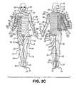
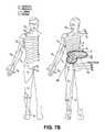
- FIG. 3Cillustrates the various dermatomes of the body related to their respective nerve roots in FIG. 3B ;
- FIG. 4Aillustrates a single electrode, single level activation pattern and FIG. 4B illustrates an exemplary corresponding dermatome to the stimulation pattern of FIG. 4A ;
- FIG. 5Aillustrates a single electrode per level, two level activation pattern and FIG. 5B illustrates an exemplary corresponding dermatome to the stimulation pattern of FIG. 5A ;
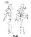
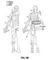
- FIG. 6Aillustrates a two electrode, single level activation pattern and FIG. 6B illustrates an exemplary corresponding dermatome to the stimulation pattern of FIG. 6A ;
- FIG. 7Aillustrates a single electrode level and a two electrode level activation pattern and FIG. 7B illustrates an exemplary corresponding dermatome to the stimulation pattern of FIG. 7A ;
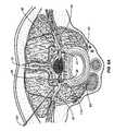
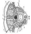
- FIG. 8Ais a section view of a spinal level with an electrode being implanted into a dorsal root ganglia and FIG. 8B is the view of FIG. 8A with the delivery catheter being withdrawn and the electrode implanted into the dorsal root ganglia;
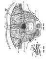
- FIG. 9Ais a section view of a spinal level with an electrode being implanted into a dorsal root ganglia using an approach that crosses a medial line of the level of interest and FIG. 9B is an enlarged view of the DRG in FIG. 9A with an implanted electrode;
- FIG. 10Ais a section view of a spinal level with an electrode being implanted onto or in the nerve root epinurium using an approach that crosses a medial line of the level of interest and FIG. 10B is an enlarged view of the implanted electrode in FIG. 10A ;
- FIG. 11is a illustrates an alternative DRG implantation technique using an approach along the peripheral nerve
- FIG. 12Aillustrates an implantation technique using an electrode and anchor design illustrated in FIG. 12B ;
- FIG. 12Billustrates an anchor body and hook mounted onto the distal end of the catheter
- FIG. 12Cillustrates an alternative anchoring technique using the surrounding vertebral bone
- FIG. 13Aillustrates the monopolar stimulation component embodiment illustrated in FIG. 13B implanted in a DRG
- FIG. 13Billustrates a stimulation component having an anchoring mechanism and a mono-polar electrode
- FIG. 14Aillustrates the bi-polar stimulation component embodiment illustrated in FIG. 14B implanted in a DRG
- FIG. 14Billustrates a stimulation component having an anchoring mechanism and a bi-polar electrode
- FIG. 15Ais a chart illustrating the relationship between impedance and electrode surface area
- FIG. 15Bis a chart illustrating representative electrode areas for stimulation components of several embodiments of the invention.
- FIGS. 16-20are various alternative electrode embodiments
- FIG. 20Aillustrates an electrode adapted to pierce through and anchor to targeted neural tissue
- FIG. 20Billustrates a securing ring adapted for use with the electrode in FIG. 20A ;
- FIG. 20Cillustrates a piercing electrode embodiment in position to stimulate a ganglion in the sympathetic chain
- FIG. 20Dillustrates a piercing electrode embodiment in position to stimulate a dorsal root ganglion
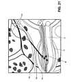
- FIG. 21illustrates a coated electrode implanted into a DRG
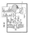
- FIG. 22illustrates the position of the DRG upstream of various a number of stimulation mechanisms
- FIG. 23Aillustrates a combination stimulation and agent delivery electrode that provides the threshold adjustment illustrated in FIG. 23B ;
- FIG. 23Billustrates exemplary A-fiber and C-fiber responses relative to a threshold
- FIGS. 23C and 23Dillustrate combined stimulation and pharmacological agent delivery electrodes and systems
- FIG. 24is a table listing several exemplary pharmacological agents and their uses.
- FIG. 25is a illustration of Na and Ca channel blocking targets to mitigate c-fiber activity
- FIG. 26is a schematic drawing of an embodiment of a pulse generator
- FIG. 27is a schematic drawing of an electrode connector embodiment
- FIG. 28is an alternative single pulse generator stimulation system embodiment
- FIG. 29is an alternative embodiment of a multi-pulse generator stimulation system with generators in a master-slave arrangement
- FIG. 30is an embodiment of a stimulation system adapted to treat conditions in spinal levels C 1 -C 3 ;
- FIGS. 31A and 31Billustrate, respectively, the result of stimulation provided by embodiments of the present invention to increase sub-threshold signals above a threshold level
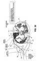
- FIG. 32is an illustration of the sympathetic nervous system
- FIG. 33is an illustration of a portion of sympathetic nervous system neuromodulated by an stimulation system embodiment of the present invention.
- FIG. 34is an illustration of embodiments of the present invention implanted for the direct stimulation of a single sympathetic nerve ganglion and a single dorsal root ganglion on the same spinal level;
- FIG. 35is an illustration of an embodiment of the present invention implanted for the direct stimulation of the spinal cord
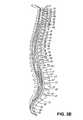
- FIG. 36is an illustration of two embodiments of the present invention implanted for the direct stimulation of the spinal cord
- FIGS. 37A-37Cillustrate sealing embodiments used when implanting electrodes into the spinal cord.
- FIG. 38summarizes numerous alternative embodiments of the stimulation system of the present invention as applied to different portions of the spine and dorsal root ganglion.
- Embodiments of the present inventionprovide novel stimulation systems and methods that enable direct and specific neurostimulation techniques.
- a method of stimulating a nerve root ganglioncomprising implanting an electrode into the nerve root ganglion and activating the electrode to stimulate the nerve root ganglion.
- the nerve root ganglionmay be a dorsal root ganglion in some embodiments while in other embodiments the nerve root ganglion may be a nerve root ganglion in the sympathetic nervous system or other ganglion or tissue.
- implanting the electrodeincludes forming an opening in the epinurium of the root ganglion and passing the electrode through the opening and into the interior space or interfascicular space of the ganglion.
- portions of an electrode bodypass completely through a ganglion while maintaining an active electrode area appropriately positioned to deliver stimulation energy to the ganglion.
- the size, shape and position of a microelectrode and the stimulation pattern or algorithmis chosen to stimulated targeted neural tissue and exclude others.
- the electrode stimulation energyis delivered to the targeted neural tissue so that the energy dissipates or attenuates beyond the targeted tissue or region.
- the activating stepproceeds by coupling a programmable electrical signal to the electrode.
- the amount of stimulation energy provided into the nerve ganglionis sufficient to selectively stimulate neural tissue.
- the stimulation energy providedonly stimulates neural tissue within the targeted DRG.
- the stimulation energy beyond the DRGis below a level sufficient to stimulate, modulate or influence nearby neural tissue.
- the stimulation levelmay be selected as one that preferentially activates myelinated, large diameter fibers (such as A ⁇ and A ⁇ fibers) over unmyelinated, small diameter fibers (such as c-fibers).
- the stimulation energy used to activate an electrode to stimulate neural tissueremains at an energy level below the level to used ablate, lesion or otherwise damage the neural tissue.
- an electrodeis placed into a dorsal root ganglia and activated until a thermolesion is formed (i.e., at a electrode tip temperature of about 67° C.) resulting in a partial and temporary sensory loss in the corresponding dermatome.
- the stimulation energy levels applied to a DRGremain below the energy levels used during thermal ablation, RF ablation or other rhizotomy procedures.
- Tissue stimulationis mediated when current flow through the tissue reaches a threshold, which causes cells experiencing this current flow to depolarize.
- Currentis generated when a voltage is supplied, for example, between two electrodes with specific surface area.
- the current density in the immediate vicinity of the stimulating electrodeis an important parameter. For example, a current of 1 mA flowing through a 1 mm 2 area electrode has the same current density in its vicinity as 10 mA of current flowing through a 10 mm 2 area electrode, that is 1 mA/mm 2 .
- cells close to the electrode surfaceexperience the same stimulation current. The difference is that the larger electrode can stimulate a larger volume of cells and the smaller electrode can stimulate a smaller volume of cells in proportion to their surface area.
- the preferred effectis to stimulate or reversibly block nervous tissue.
- blockor “blockade” in this application means disruption, modulation, and inhibition of nerve impulse transmission. Abnormal regulation can result in an excitation of the pathways or a loss of inhibition of the pathways, with the net result being an increased perception or response.
- Therapeutic measurescan be directed towards either blocking the transmission of signals or stimulating inhibitory feedback. Electrical stimulation permits such stimulation of the target neural structures and, equally importantly, prevents the total destruction of the nervous system. Additionally, electrical stimulation parameters can be adjusted so that benefits are maximized and side effects are minimized.
- FIG. 2Aillustrates an embodiment of a stimulation system 100 of the present invention in place with an electrode 115 implanted into a spinal dorsal root ganglion 40 .
- spinal level 14a sub-section of the spinal cord 13 , is used to depict where the dorsal root 42 and ventral root 41 join the spinal cord 13 , indicated by 42 H and 41 H respectively.
- the peripheral nerve 44divides into the dorsal root 42 and dorsal root ganglion 40 and the ventral nerve root 41 .
- the spinal dura layer 32surrounds the spinal cord 13 and is filled with cerebral spinal fluid (CSF).
- CSFcerebral spinal fluid
- the spinal dura layer or dura mater 32 aloneis used to represent the three spinal meninges—the pia mater, the arachnoid mater and the dura mater—that surround and protect the spinal cord 13 .
- the electrode 115is implanted medial to the peripheral nerve 44 after the nerve root splits into the ventral nerve 41 containing the motor nerves and the dorsal root 42 containing the sensory nerves.
- the electrode 115is also implanted lateral of the dura layer 32 .
- the advantageous placement of one or more electrode embodiments of the present inventionenables selective stimulation of neural tissue, such as a nerve root ganglion, without stimulation of surrounding neural tissue.
- a dorsal root ganglion 40is stimulated with little or imperceptible amounts of stimulation energy provided to the motor nerves within the ventral nerve root 44 , portions of the spinal cord 13 , spinal level 14 , or the peripheral nerve 44 .
- Embodiments of the present inventionare particularly well suited for providing pain control since the sensory fibers running through the dorsal root ganglion 40 may be specifically targeted.
- embodiments of the present inventionmay neuromodulate one or more the dorsal root ganglia for pain control without influencing surrounding tissue.
- the stimulation system 100includes a pulse generator that provides stimulation energy in programmable patterns adapted for direct stimulation of neural tissue using small area, high impedance microelectrodes.
- the level of stimulation providedis selected to preferentially stimulate the A ⁇ and A ⁇ fibers 52 over the c-fibers 54 .
- Stimulation energy levels used by embodiments of the present inventionutilize lower stimulation energy levels than conventional non-direct, non-specific stimulations systems because the electrode 115 is advantageously placed on, in or about a dorsal root ganglion 40 .
- the signal 53 from the fibers 52will release opiates at the junction of the dorsal root 42 and the spinal cord 13 . This release raises the response threshold at that junction (elevated junction threshold 56 ). The later arriving c-fiber signal 55 remains below the elevated junction threshold 56 and goes undetected.
- some embodiments of the present inventionprovide selective stimulation of the spinal cord, peripheral nervous system and/or one or more dorsal root ganglia.
- selective stimulationmeans that the stimulation substantially only neuromodulates or neurostimulates a nerve root ganglion.
- selective stimulation of a dorsal root ganglionleaves the motor nerves unstimulated or unmodulated.
- selective stimulationcan also mean that within the nerve sheath, the A-myelinated fibers are preferentially stimulated or neuromodulated as compared to the c-unmyelinated fibers.
- embodiments of the present inventionadvantageously utilize the fact that A-fibers carry neural impulses more rapidly (almost twice as fast) as c-fibers.
- Some embodiments of the present inventionare adapted to provide stimulation levels intended to preferentially stimulate A-fibers over c-fibers.
- selective stimulationcan also mean that the electrode (including an electrode coated with or adapted to deliver a pharmacological agent, e.g., FIGS. 21 , 23 A, C and D) is in intimate contact with the tissue or other nervous system component that is the subject of stimulation. This aspect recognizes our advantageous use of electrode placement.
- one or more stimulation electrodesare placed (1) against or in contact with the outer sheath of a nerve root ganglion; (2) within a nerve root ganglion; (3) within the root ganglion interfascicular space; (4) in contact with a portion of the spinal cord; (5) in a position that requires piercing of the epidural space, the dura, nerve root epinurium or a portion of the spinal cord; (6) in contact with a portion of the sympathetic nervous system or (7) in contact with neural tissue targeted for direct stimulation.
- selective stimulation or neuromodulation concepts described hereinmay be applied in a number of different configurations. Unilateral (on or in one root ganglion on a level), bi-lateral (on or in two root ganglion on the same level), unilevel (one or more root ganglion on the same level) or multi-level (at least one root ganglion is stimulated on each of two or more levels) or combinations of the above including stimulation of a portion of the sympathetic nervous system and one or more dorsal root ganglia associated with the neural activity or transmission of that portion of the sympathetic nervous system.
- embodiments of the present inventionmay be used to create a wide variety of stimulation control schemes, individually or overlapping, to create and provide zones of treatment.
- FIG. 3Aillustrates an embodiment of a stimulation system 100 of the present invention with an electrode 115 implanted into a dorsal root ganglion (DRG) 40 .
- the figureillustrates three representative spinal levels 14 (i.e., spinal levels 1 - 3 ) of the spinal cord 13 .
- the peripheral nerve 44feeds into the dorsal root ganglion 40 and the ventral nerve root 41 each of which feed into the spinal cord 13 .
- the dorsal horns 37 , 36are also indicated.
- the dura 32 and complete spinal cord 13are not illustrated but are present as described elsewhere in this application and as occur in human anatomy.
- These exemplary levels 1 , 2 and 3could be anywhere along the spinal cord 13 .
- each levelillustrates the nerves of only one side.
- an ascending pathway 92is illustrated between level 2 and level 1 and a descending pathway 94 is illustrated from level 2 to level 3 .
- Application of stimulation energy or signals to the DRG 40 in level 2may be used to block signals progressing upstream from level 2 towards the path/pathways 92 .
- modulation applied to portions of level 2may also be used to effectively block the neuron paths/pathways from another level (here, alternatively using levels 1 and/or 3 ) from reaching the brain.
- application of stimulation to the level 2 DRG 40 using an embodiment of an apparatus and/or method of the present inventionmay advantageously provide an effective block of intrasegment pain pathways as well. It is to be appreciated that while three continuous levels are illustrated, some embodiments of the present invention may be used to stimulate 2 or more adjacent levels and still other embodiments may be used to stimulate 2 or more non-adjacent levels, or combinations thereof.
- FIG. 3Brelates the spinal nerve roots to their respective vertebral spinal levels.
- the letter Cdesignates nerves and vertebrae in the cervical levels.
- the letter Tdesignates vertebrae and nerves in the thoracic levels.
- the letter Ldesignates vertebrae and nerves in the lumbar levels.
- the letter Sdesignates vertebrae and nerves in the sacral levels.
- FIG. 3Cillustrates the various dermatomes of the body related to their respective nerve roots using the designations in FIG. 3B .
- FIGS. 4-7illustrate one embodiment of a stimulation system activated under a variety of control conditions to provide different levels and degrees of pain control.
- FIGS. 4A , 5 A, 6 A and 7 Aall illustrate the stimulation system in various degrees of activation.
- FIGS. 4B , 5 B, 6 B and 7 Billustrate a correspondingly influenced dermatome.
- FIGS. 4A , 5 A, 6 A and 7 Aillustrate a stimulation system 100 having 3 electrodes 115 implanted into dorsal root ganglia 40 on two adjacent spinal levels.
- each spinal levelillustrates a dorsal root ganglion 40 , a ventral root 41 and a peripheral nerve 44 .
- spinal level 3illustrates an additional dorsal root ganglion 38 , a ventral root 39 and a peripheral nerve 42 .
- the three electrodes 115are designated channels 1 , 2 and 3 by the controller 106 .
- Each electrodeis activated to provide modulation energy or signals under the control of the controller 106 .
- Exemplary electrodes for implantation into a nerve root ganglionare further described with regard to FIGS. 12A-13B .
- Level 3is an example of bilateral electrode placement and level 2 is an example of unilateral electrode placement.
- the illustrated embodimentis a multi-level, unilateral and bi-lateral stimulation system.
- Stimulation energyis provided by a pulse generator (not illustrated but described in greater detail below in FIGS. 26-29 ) under control of a suitable neurostimulation controller 106 .
- a suitable neurostimulation controller 106Any of a wide variety of known neurostimulation controllers may be used.
- suitable connections between the various electrodes 115 , electrode leads 110 and the controller 106Not illustrated in this view but present in the system are suitable connections between the various electrodes 115 , electrode leads 110 and the controller 106 .
- a line connecting the electrode lead 110 to the controller 106indicates “stimulation on” communication from the controller 106 to one electrode 115 (see FIG. 4A ) or more than one electrode 115 (see FIG. 5A ).
- a signal of “stimulation on”indicates any of a wide variety of stimulation patterns and degrees of stimulation.
- the “stimulation on” signalmay be an oscillating electrical signal may be applied continuously or intermittently. Furthermore, if an electrode is implanted directly into or adjacent to more than one ganglion, the oscillating electrical signal may be applied to one electrode and not the other and vice versa.
- the application of the oscillating electrical signalstimulates the area of the nerve chain where the electrode 115 is placed. This stimulation may either increase or decrease nerve activity.
- the frequency of this oscillating electrical signalis then adjusted until the symptoms manifest by physiological disorder being treated has been demonstrably alleviated. This may step may be performed using patient feedback, sensors or other physiological parameter or indication. Once identified, this frequency is then considered the ideal frequency. Once the ideal frequency has been determined, the oscillating electrical signal is maintained at this ideal frequency by storing that frequency in the controller.
- the oscillating electrical signalis operated at a voltage between about 0.5 V to about 20 V or more. More preferably, the oscillating electrical signal is operated at a voltage between about 1 V to about 30 V or even 40V. For micro stimulation, it is preferable to stimulate within the range of 1V to about 20V, the range being dependent on factors such as the surface area of the electrode.
- the electric signal sourceis operated at a frequency range between about 10 Hz to about 1000 Hz. More preferably, the electric signal source is operated at a frequency range between about 30 Hz to about 500 Hz.
- the pulse width of the oscillating electrical signalis between about 25 microseconds to about 500 microseconds. More preferably, the pulse width of the oscillating electrical signal is between about 50 microseconds to about 300 microseconds.
- the application of the oscillating electrical signalmay be provided in a number of different ways including, but not limited to: (1) a monopolar stimulation electrode and a large area non-stimulating electrode return electrode; (2) several monopolar stimulating electrodes and a single large area non-stimulating return electrode; (3) a pair of closely spaced bi-polar electrodes; and (4) several pairs of closely spaced bi-polar electrodes.
- Other configurationsare possible.
- the stimulation electrode(s) of the present inventionmay be used in conjunction with another non-stimulating electrode—the return electrode—or a portion of the stimulation system may be adapted and/or configured to provide the functionality of a return electrode.
- Portions of the stimulation system that may be adapted and/or configured to provide the functionality of the return electrodeinclude, without limitation, the battery casing or the pulse generator casing.
- a stimulation pattern provided to one of the electrodes positioned in level 3i.e., channel # 1 “ON”
- produces pain blocking/relief in the indicated region of the bodyi.e., shaded area R 1 ) in FIG. 4B .
- embodiments of the present inventioncan stimulate specific dermatome distributions to probe which electrode or group of electrodes or combination of electrodes (including drug coated or delivery electrodes) is best positioned or correlates most closely to one or more specific areas of pain.
- a stimulation systemaccording to an embodiment of the present invention may be “fine tuned” to a specific area of coverage or type of pain. The results obtained from such testing can be used to one or more stimulation or treatment regimes (i.e., series of stimulations in the presence of or in combination with a therapeutic agent from a coated electrode) for a particular patent for a particular type of pain.
- stimulation or treatment regimesi.e., series of stimulations in the presence of or in combination with a therapeutic agent from a coated electrode
- These pain treatment regimesmay be programmed into a suitable electronic controller or computer controller system (described below) to store the treatment program, control and monitor the system components execution of the stimulation regime as the desired therapeutic regime is executed.
- FIG. 5Aprovides another example of distribution of pain relief using a multi-channel stimulation system and method.
- a stimulation patternis provided to one electrode each in levels 2 and 3 via channels # 1 and # 2 .
- This stimulation electrode patternprovides pain blocking/relief in the indicated region of the body (i.e., areas R 1 , R 2 ) of FIG. 5B .
- FIG. 6Aprovides another example of distribution of pain relief using a multi-channel stimulation system and method.
- a stimulation pattern provided to both electrodes in level 3 via channels # 1 and # 3provides pain blocking/relief in the indicated region of the body (i.e., area R 3 ) of FIG. 6B .
- FIG. 7Aprovides another example of distribution of pain relief using a multi-channel stimulation system and method.
- a stimulation patternis provided to all electrodes in the system via channels # 1 , # 2 and # 3 .
- This stimulation electrode patternprovides pain blocking/relief in the indicated region R 4 of the body (i.e., FIG. 7B ).
- FIGS. 4A-7Bmay be modified using information such as in FIGS. 3B and 3C for targeted placement to specific portions of the body depending upon individual needs.
- Micro-electrode and stimulation system embodiments of the present inventionmay be implanted into a single nerve root ganglion utilizing the implantation methods of the present invention.
- the implantation methods described hereinprovide numerous advantages, including but not limited to: low risk percutaneous access route similar to other procedures, direct delivery of localized quantities of pharmacological agents at the nerve root when using embodiment having electrodes coated with pharmacological agents, and electrode placement that enables preferential, selective nerve fiber stimulation.
- FIG. 8Aillustrates a cross section view of a spinal level.
- Peripheral nerves 44 , 42feed into dorsal root ganglia 40 , 38 and ventral nerves 41 , 39 respectively.
- a vertebral body 70 and two sympathetic nerve ganglia 62 , 63are also illustrated.
- the methodincludes advancing a suitable catheter 107 medially towards the vertebral body 70 , then along the peripheral nerve 42 towards the dorsal root ganglion 38 .
- the catheter 107is advanced using external imaging modalities for guidance such as fluoroscopy or other suitable medical imaging technique.
- the vertebral foramenoffers a good landmark visible under fluoroscopy and useful in locating the DRG 38 .
- the electrode 115is implanted in proximity to the dorsal root ganglion by forming an opening in the dorsal root ganglion epinurium and passing the electrode through the opening ( FIG. 8A , 8 B).
- the openingmay be formed using conventional methods such as a cutting edge on or provided to the tip of the catheter 107 , with an instrument advanced through a working channel within the catheter 107 or through the use of other suitable endoscopic or minimally invasive surgical procedure.
- the electrode body or distal endmay be provided with a tissue cutting or piercing element to aid in piercing tissue (see, e.g., tip 908 in FIG. 20A ).
- the microelectrode leads 110are deployed and attached, anchored or otherwise secured to the tissue, anatomy or bones adjacent the DRG 38 to reduce the likelihood that electrode 115 will be pulled from the DRG 38 .
- the microelectrode leads 110may be fixed prior to electrode implantation into a nerve root ganglion.
- the electrode 115is sized and shaped to fit within the DRG 38 .
- a typical DRGis generally spherical with a diameter of 3-5 mm.
- Electrode embodimentsmay be provided in a range of sizes to accommodate the specific anatomical characteristics of a patient. A number of factors are considered when selecting an appropriate DRG electrode embodiment for use in an individual.
- Electrode placement within the DRGmay be confirmed using neurodiagnostic testing techniques such as somatosensory evoked potential (SSEP) and electromyography (EMG) adapted for the methods and systems described herein.
- SSEPsomatosensory evoked potential
- EMGelectromyography
- One illustrative exampleincludes the placement of sensing electrodes in the sensory nervous system above and below the DRG level having the implanted electrode(s). Implant the electrode into the targeted DRG. Apply a test stimulation to the DRG and measure voltage potential at the sensory electrodes above and below the targeted DRG to confirm that the electrode is implanted in the targeted DRG.
- a test stimulationmay range from 0.4 v to 0.8 v at 50 Hz or may be some other suitable stimulation level based on the evoked potential measurement technique used.
- conventional fluoroscopy techniques and instrumentsmay be used to advance towards and implant the electrode into the DRG and confirm that the electrode is correctly implanted and stimulating the targeted DRG.
- FIGS. 8-10A number of different approaches are available for maneuvering an electrode into position on, in or about a DRG.
- FIGS. 8-10Several exemplary approaches are provided in FIGS. 8-10 in a section view of the cauda equina portion of the spinal cord.
- electrodes 115are placed on or in a ganglion on a representative sacral spinal level.
- Sympathetic nervous system ganglia 62 , 63are also indicated.
- DRG 40 and ventral root 41are associated with peripheral nerve 44 .
- DRG 38 and ventral root 39are associated with peripheral nerve 42 .
- FIGS. 8A and 8Billustrate a lateral approach to a DRG 38 using a suitable catheter 107 .
- the catheteradvances adjacent to the peripheral nerve 42 medially towards the DRG 38 .
- the DRG durais pierced laterally and the electrode 115 is advanced into the DRG interior. Thereafter, the electrode 115 is implanted into the DRG interior.
- the catheter 107is withdrawn from the DRG 38 and deploys the electrode leads 110 .
- the electrode leads 110may be anchored to the vertebral body 70 using suitable fixation techniques.
- the leads 110are then connected to a pulse generator/controller (not shown).
- FIG. 9Ais anatomically similar to FIGS. 8A and 8B .
- FIG. 9Aillustrates an alternative DRG implantation approach that crosses the medial line inferior to the DRG of interest.
- the catheter 107is advanced in a superior pathway towards the foramen and using the foramen under fluoroscopic guidance into the DRG.
- FIGS. 9A and 9Bthere is provided a method of stimulating a dorsal root ganglion by implanting an electrode within the dorsal root ganglion.
- the implanting procedureincludes passing a portion of the electrode through the spinal epidural space. Electrodes in systems of the present invention onto or in the nerve root epinurium 72 ( FIGS.
- FIGS. 9 A,Bthere is also the step of forming an opening in the dorsal root ganglion epinurium 72 and then passing the electrode through the opening (see, i.e., FIG. 9B ).
- FIG. 11illustrates a section view through a portion of the spinal cord 13 with another alternative electrode implantation technique.
- FIG. 11illustrates an internal approach to the DRG interlascular from within the nerve sheath of a peripheral nerve 44 .
- FIG. 11illustrates a section view of the nerve sheath partially removed to reveal the underlying nerve bundle 46 .
- an openingis made in the peripheral nerve 44 sheath at a point 45 lateral to the DRG 40 .
- the microelectrode 115enters the nerve 44 sheath through opening 45 using suitable endoscopic or minimally invasive surgical techniques. Next, the electrode 115 is advanced towards and into the DRG 40 .
- the placement of the electrode relative to the DRGenables activating the electrode to selectively stimulate sensory nerves. Additionally, the placement of the electrode according to the methods of the invention enable activating the electrode to stimulate sensory nerves within the DRG or without stimulating motor nerves in the nearby ventral root.
- the control system described hereinalso provides stimulation levels that activate the electrode to stimulate at a level that preferably stimulates myelinated fibers over unmyelinated fibers.
- FIG. 11illustrates an electrode embodiment where the electrode tip and shaft may be coated with pharmacological agents to assist in the stimulation therapy or provide other therapeutic benefit.
- the electrodeincludes a tip coating 130 and a shaft coating 132 .
- the pharmacological agent in each coating 130 , 132could be the same or different.
- One advantage of implanting through the nerve sheathis that the coated shaft 132 may include a pharmacological agent active or beneficial to neural activity in the ventral nerve root 41 since this coated shaft is advantageously positioned proximal to the ventral root 41 .
- the shaft coating 132may also be selected to reduce inflammation or irritation caused by the presence of the shaft within the nerve sheath.
- FIGS. 12A and 12Billustrate an embodiment of an exemplary anchor body 171 with a fixation hook 172 used to secure the leads 110 once the electrode 115 is implanted into the DRG 40 .
- FIG. 12Ais a section view of a portion of the spinal cord 13 showing the dorsal root 42 , ventral root 41 , DRG 40 and peripheral nerve 44 .
- a catheter 70is used to maneuver the electrode 115 , leads 110 and anchor 171 about the DRG 40 implantation site.
- the hook 172is inserted into the fascia layer of the DRG.
- the hook 172may have various shapes and contours to adapt it to engaging with and securing to the outer DRG layer or within the outer DRG layer.
- FIG. 12Ais a section view of a portion of the spinal cord 13 showing the dorsal root 42 , ventral root 41 , DRG 40 and peripheral nerve 44 .
- a catheter 70is used to maneuver the electrode 115 , leads 110 and anchor 171 about the DRG 40
- FIG. 12Billustrates an exemplary anchor body 171 and hook 172 mounted onto the distal end of a catheter 70 .
- the anchor body 171 and hook 172may be maneuvered into position using the catheter 70 alone or in combination with other suitable surgical, endoscopic or minimally invasive tools.
- the electrode 115 , leads 110may be moved into position for implantation on, in or about targeted neural tissue.
- the electrode 115is implanted on, in or about a DRG is provided with a flexible tip that helps to prevent or mitigate chronic friction and ulceration.
- the electrode leads 110 or other supporting or anchoring structuresmay be attached to the adjacent bony structure, soft tissue or other neighboring anatomical structures.
- a fixation, anchoring or bonding structurepositioned proximal to the electrode anchor 172 that absorbs some or all proximal movement of the leads 110 so that the electrode is less likely to be pulled from or dislodged from the implantation site.
- the goal of the anchoring and other strain absorbing featuresis to ensure the electrode remains in place within or is less likely to migrate from the implanted position because of electrode lead 110 movement (i.e., lead 110 movement pulls the electrode 115 from the implantation site or disrupts the position of the electrode 115 within the implantation site).
- Electrodesmay also be adapted for attachment to surrounding tissue in proximity to the stimulation site or near the electrode implantation site.
- Other componentsinclude, for example, the stimulation controller, master controller, slave controller, pulse generator, pharmacological agent reservoir, pharmacological agent pump and the battery.
- FIG. 12Cillustrates an exemplary anchoring of electrode leads 110 to bone surrounding the electrode implantation site.
- FIG. 12Cillustrates a section view through a portion of the spinal cord 13 showing the ventral root 41 , the dorsal root 42 and dorsal root ganglion 40 .
- FIG. 12Calso illustrates the surrounding bone of the spine such as vertebral body 1110 , the spinous process 1115 , the pedicle 1120 , the lamina 1125 , the vertebral arch 1130 , transverse process 1135 , and facet 1140 .
- Electrode 115is implanted into the DRG 40 and the electrode leads are held in place using a suitable anchor 111 .
- the anchor 111is secured to the vertebral body 1110 .
- the anchor 111represents any suitable manner of securing the bony portions of the spine such as tacks, staples, nails, cement, or other fixation methods known to those in the surgical or orthopedics arts.
- a strain relief 122is present between anchor 111 and the DRG 40 (see FIGS. 13A and 14A ).
- the strain relief 122is used to absorb motion that may move the electrode 115 within the DRG 40 or remove the electrode from the DRG 40 .
- the strain relief 122is a coiled portion of the electrode lead 110 .
- One or more strain reliefs 122may be provided between the anchor 111 and the DRG 40 or between the anchor 111 and the battery or controller of the stimulation system (not shown).
- FIGS. 13A-14Billustrate mono-polar and bi-polar stimulation component embodiments of the present invention.
- FIG. 13Aillustrates a mono-polar stimulation component that has a proximal connector 126 A adapted to be connected to a pulse generator.
- a distal electrode 115is configured to be implanted within the body at a stimulation site.
- the distal electrodemay be a mono-polar electrode 115 A ( FIG. 13B ) or a bi-polar electrode 115 B ( FIG. 14B ).
- the electrodesare sized for implantation into a nerve root ganglion and will vary according to the nerve root selected.
- the electrode leads and electrodeare adapted and sized to advance within a nerve sheath to a nerve root ganglion.
- the electrodes or their casingmay be made of inert material (silicon, metal or plastic) to reduce the risk (chance) of triggering an immune response. Electrodes should be studied for suitability to MRI and other scanning techniques, including fabrication using radio-opaque materials as described herein.
- an electrical lead 110is connected to the proximal connector 126 A and the distal electrode 115 .
- a strain relief mechanism 122is connected in proximity to the stimulation site.
- the illustrated strain relief mechanismis formed by coiling the electrical lead 110 .
- Other well known strain relief techniques and devicesmay be used.
- a fixation element 124 adapted to reduce the amount of movement of the electrical lead proximal to a fixation pointis positioned in, on, or through an anatomical structure proximal to the stimulation site.
- strain and movementmay be absorbed or mitigated by the fixation element 124 , the strain relief 122 and the electrode anchor 117 (if included).
- the fixation element, 124may be, for example, a loop, or a molded eyelet.
- the fixation elementmay be sutured, tacked, screwed, stapled, bonded using adhesives or joined using other techniques known to those of ordinary skill to secure the fixation element within the body for the purposes described herein.
- the method of implanting the electrodeis modified based on consideration of the small size and delicate nature of the microelectrode and microelectrode leads. As such, high force actions are taken first followed by light force actions. In this way, the fine microelectrode and microelectrode lead materials are not present during high force operations.
- the fixation element 124is a loop sized to allow passage of the electrode 115 . Perform the high force operation of anchoring or otherwise fixing (i.e., adhesion) the fixation element into a vertebral foramen adjacent the selected DRG stimulation site.
- the fixation siteshould be as close as practical to the stimulation site. In one specific embodiment, the fixation site is within 3 cm to 5 cm of the stimulation site.
- a guide wire attached to the loopremains in place and is used to guide the electrode and leads to the loop and hence to the implant site. The electrode and leads are passed through the loop (with or without use of a guide wire). The electrode is then implanted on or in the DRG.
- an anti-strain device 122may also be positioned between the electrode in the implantation site and the fixation element 124 . In one illustrative embodiment, a section of microelectrode lead containing a plurality of loops is used as an anti-strain device 122 .
- microelectrode leadis secured to the loop using a suitable locking device. It is to be appreciated that the above method is only illustrative of one method and that the steps described above may be performed in a different order or modified depending upon the specific implantation procedure utilized.
- an anchoring mechanismproximal to the distal electrode 115 .
- anchoring mechanismsinclude, for example, anchors 117 illustrated in FIGS. 13B and 14B .
- the anchoring mechanismis adapted to anchor the distal electrode 115 within the stimulation site.
- the anchor mechanismmay remain stowed flat against the electrode body 118 during implantation and then deploy from within a nerve root ganglion to anchor against the interior nerve root wall to support the electrode and prevent electrode migration or pull-out.
- the anchoring mechanism and the distal electrodeare integrally formed and in other embodiments they are separate components.
- the anchoring mechanismis formed from a polymer or a silicone.
- ElectrodesSmaller electrodes create less impingement and are less susceptible to unwanted migration.
- the impedance of the electrodeincreases ( FIG. 15A ).
- some electrode embodimentswill have an impedance much greater than the impedance of conventional stimulation electrodes.
- the impedance of a microelectrode of the present inventionis more than 2500 ⁇ . This difference in impedance also impacts the performance requirements of stimulation systems, pulse generators and the like used to drive the microelectrodes described herein.
- Distal electrodesmay come in a wide variety of configurations, shapes and sizes adapted for implantation into and direct stimulation of nerve root ganglion.
- the distal electrode 115may be a ring of conductive material attached the leads 110 .
- the distal electrode 115may be formed from an un-insulated loop of electrical lead.
- the loop electrodeis appealing and has improved wear properties because, unlike the ring that must be joined to the leads 110 , the loop is formed from the lead and no joining is needed.
- the electrodemay be an un-insulated portion of the lead.
- electrodes of the present inventionare sized and adapted for implantation into, on or about a ganglion such as, for example, a dorsal root ganglion or a ganglion of the sympathetic nervous system. It is to be appreciated that the size of the electrode varies depending upon the implantation technique and the size of the target ganglion.
- An electrode implanted through the DRG durai.e., FIG. 9A
- An electrode implanted through the DRG duramay be less than 5 mm since the diameter of a DRG may be only 3-5 mm.
- an electrode adapted for implantation along the peripheral nerve sheathi.e., FIG.
- Electrodes 11may be longer than the electrode that passes through the dura but may face other design constraints since it must advance distally within the nerve sheath to reach the DRG. It is to be appreciated that dimensions of electrode embodiments of the present invention will be modified based on, for example, the anatomical dimensions of the implantation site as well as the dimensions of the implantation site based on implantation method.
- FIG. 15Bprovides some exemplary electrode surface areas for electrode embodiments formed from wire diameters between 0.25 mm to 1 mm, having widths of 0.25 mm or 0.5 mm.
- embodiments of the present inventionprovide distal electrode surface area that is less than 0.5 mm 2 .
- the distal electrode surface areais less than 1 mm 2 .
- the distal electrode surface areais less than 3 mm 2 .
- the sizes of the electrodes-of the present inventionstand in contrast to the conventional paddle 5 having dimensions of about 8 mm wide and from 24 to 60 mm long ( FIG. 1 ).
- conventional stimulation electrodeshave larger electrode surface areas than electrode embodiments of the present invention.
- conventional electrodeshave an impedance on the order of 500 to 1800 ⁇ operated using a stimulation signal generated by a 10-12 volt pulse generator.
- stimulation electrode embodiments of the present inventionhave an impedance on the order of 2 k ⁇ or about 2500 ⁇ , from 2 k ⁇ to 10 k ⁇ or higher or even in the range of 10 k ⁇ to 20 k ⁇ .
- some pulse generator embodiments of the present inventionoperate with voltages produced by DC-DC conversion into ranges beyond conventional stimulation systems.
- the electrodesmay be formed from materials that are flexible and have good fatigue properties for long term use without material failure.
- the electrode materialshould be formed from a biocompatible material or coated or otherwise treated to improve biocompatibility. Additionally, electrode materials should be opaque to imaging systems, such as fluoroscopy, used to aid electrode placement during implantation procedures. Examples of suitable materials include but are not limited to Pt, Au, NiTi, PtIr and alloys and combinations thereof. Electrodes may also be coated with a steroid eluding coating to reduce inflammation at the implantation or stimulation site.
- microelectrodesWith the small surface areas, the total energy required for stimulation of the DRG is drastically reduced because we can achieve high current densities with low currents.
- One advantage of using microelectrodesis that only a small volume of tissues in the immediate vicinity of the electrodes is stimulated.
- Another advantage of using microelectrodesis the correspondingly smaller pulse generator and because of decreased battery size.
- FIG. 16illustrates an embodiment where conductive rings 205 , 207 are positioned on either end of a dorsal root ganglion 40 . When activated, the rings 205 , 207 capacitively couple stimulation energy into the DRG 40 .
- FIG. 17illustrates an alternative capacitive stimulation configuration where the capacitive plates 210 , 212 are attached to the DRG dura. Embodiments of the present invention are not limited to only one pair of capacitive plates but more than one pair may be used.
- FIG. 18illustrates two pairs of capacitive plates attached to the dura of a DRG 40 .
- One pairincludes plates 210 , 212 and the other pair includes plate 214 and another plate (not shown).
- the platesmay be attached to an electrode support element 230 adapted to slip around and engage with the DRG dura ( FIG.19 ). Once the electrode support element 230 is in position about the DRG, the plates are properly positioned to selectively stimulate a DRG.
- the present inventionis not limited to only capacitively coupled stimulation energy.
- FIG. 20illustrates another alternative embodiment where a wire 235 is wrapped around a DRG 40 creating coils 236 that may be used to inductively couple stimulation energy into a nerve root ganglion. For purposes of discussion, these embodiments have been described in the context of stimulation a DRG. It is to be appreciated that the techniques and structures described herein may also be used to stimulate other nerve root ganglion, other neural structures or other anatomical features.
- FIGS. 20A and 20Billustrate another electrode embodiment adapted for implantation through neural tissue.
- Piercing electrode 900has a body 902 , a distal end 904 , and a proximal end 906 .
- a electrode surface or component 912receives stimulation signals and energy from a pulse generator/controller (not shown) via a suitable lead 914 .
- the distal and 904has a tip 908 adapted to pierce the targeted neural tissue.
- one or more anchors 910are provided at the distal end to help secure the electrode body 902 within the targeted neural tissue.
- a securing ring 920( FIG. 20B ) is provided to secure the electrode body 902 to or relative to the targeted neural tissue.
- the anchors 910may be in a first or stowed position against the electrode body 902 during insertion through the neural tissue and then be moveable into a second or deployed position away from the electrode body 902 . In the deployed position ( FIGS. 20A , 20 C and 20 D) the anchors 910 resist the movement of the electrode 900 out of the neural tissue.
- Anchor 910could be a series of individual struts arrayed in a circular pattern or struts with material between them similar to the construction of an umbrella. Anchor 910 could also be a single anchor.
- the electrode 900includes a body 902 adapted to pass completely through targeted neural tissue while positioning the electrode 912 within a portion of the targeted neural tissue.
- the electrode body 902is adapted to fit within a DRG 40 ( FIG. 20D ) or a ganglion of the sympathetic chain ( FIG. 20C ).
- the electrode 912may be placed in any location on the electrode body 902 to obtain the desired stimulation or modulation level. Additionally, the electrode 912 may be placed so that modulation or stimulation energy patterns generated by the electrode 912 will remain within or dissipate only within the targeted neural tissue.
- a securing ring 920is used to hold the electrode body 902 in position within and relative to the targeted neural tissue.
- the securing ring 920is ring shaped having an annulus 922 .
- the inner surface 942is used as a friction locking surface to engage and hold the electrode body 902 .
- the inner surface 942contains a surface treatment to secure the electrode body.
- the inner surface 942is adapted to mechanically engage with and secure the electrode body 902 .
- the securing ring 920may be formed from a suitable elastic or inelastic material that may be secured to the electrode body 902 and the outer layer of the targeted neural tissue to help prevent electrode pull out or dislodgement.
- the securing ring 920may be formed from a biocompatible material suited to gluing or mechanically affixing the ring 920 to the electrode body 902 and the tissue outer layer.
- the securing ring 920may be present during or positioned after the electrode 900 is implanted into the targeted neural tissue.
- the securing ring 920is secured to the DRG outer layer and has a complementary engaging feature positioned to engage with an engaging feature on the electrode 900 .
- the electrode body 902advances through the securing ring annulus 922 and into the DRG 40 until the complementary engaging features engage and stop further distal motion of the electrode body 902 into the DRG.
- the complementary engaging featuresmay be used alone or in combination with anchors 910 to assist in electrode 900 placement within neural tissue such as a DRG or other ganglion.
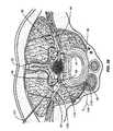
- FIGS. 20C and 20Dillustrate electrode embodiments adapted for implantation through targeted neural tissue illustrated in a section view of the spinal cord 13 . Additional details of the various portions of the spinal cord section 14 are described below with regard to FIG. 38 . Also illustrated in these views are exemplary sensory pathways 52 / 54 and motor pathways 41 P within peripheral nerve 44 and roots 41 / 42 and entering the spinal cord. Alternative implantation sites and stimulation alternatives are described in U.S. Pat. No. 6,871,099, incorporated herein by reference in its entirety.
- the electrode 900is positioned to remain in a non-central location within the targeted neural tissue.
- the targeted neural tissueis a ganglion 992 within the sympathetic chain 990 . Additional details and specific targeted neural tissue within the sympathetic chain are described below with regard to FIGS. 32 and 33 .
- the electrode 912is placed on or-in the electrode body 902 so that when the electrode body 902 passes through the ganglion 992 and is seated within the securing ring 920 the electrode 912 is in the desired position within the interior of the ganglion 992 .
- Other electrode 912 placement within the targeted neural tissueis possible, for example, by varying the length of the electrode body 902 , the angle of penetration into the targeted neural tissue or the position of initial penetration into the targeted neural tissue.
- the electrode 900is positioned to remain in a generally central location within the targeted neural tissue.
- the targeted neural tissueis a DRG 40 .
- the electrode 912is placed on or in the electrode body 902 such that when the electrode body 902 is seated within the securing ring 920 , then the electrode 912 is in the middle of about the middle or center the DRG 40 .
- the securing ring 920 and flat anchor 911secure the electrode 900 in the desired position within the DRG 40 .
- the flat or flap anchor 911provides similar functionality as the anchor 910 .
- the anchor 911has flat anchors rather than the curved anchors 910 .
- the stimulation electrode tipmay be coated with a pharmacological agent.
- a coating 130covers that portion of the electrode within the DRG 40 .
- less or more of the electrode or other implanted componentsmay be suitably coated to achieve a desired clinical outcome.
- FIG. 21also illustrates a coating 130 on the electrode shaft or portion of the electrode exterior to the DRG.
- the coating 132may be the same or different than the coating 130 .
- the tip coating 130may include a distal coating containing an agent to aid in the effective stimulation of the DRG.
- the tip coating 130may also include a more proximal coating portion (i.e., near where the electrode pierces the dura) that contains an agent to prevent fibrous growth about the electrode.
- the shaft coating 132would also contain an agent to prevent fibrous growth about the electrode. Additionally, the shaft coating 132 may be selected based on providing a pharmacological agent to interact with the tissue in the ventral root (i.e., the implantation technique in FIG. 11 ) or within the peripheral nerve sheath.
- pharmacological agents used as coatingsinclude but are not limited to reduction of scar tissue development, prevention of tissue growth or formation on the electrode, anti-inflammation, channel blocking agents and combinations thereof or other known pharmacological agents useful in treatment of pain, or neurological pathologies.
- the pharmacological agentmay include other compounds that, when placed within the body, allow the pharmacological agent to be released at a certain level over time (i.e., a time released pharmacological agent).
- the pharmacological agentis an anti-inflammatory agent, an opiate, a COX inhibitor, a PGE2 inhibitor, combinations thereof and/or another suitable agent to prevent pathological pain changes after surgery.
- Other suitable pharmacological agents that may be usedinclude those used to coat cardiac leads, including steroid eluding cardiac leads or other agents used to coat other implantable devices.
- Embodiments of the present inventioninclude direct stimulation of a nerve root ganglion or other neurological structure while releasing a pharmacological agent from an electrode used to provide stimulation.
- the pharmacological agentis released before the electrode is activated.
- the pharmacological agentis released after or during the electrode is activated.
- the pharmacological agentis pharmacologically active in the nerve root ganglion during stimulation of the nerve root ganglion. It is to be appreciated that embodiments of the present invention may be altered and modified to accommodate the specific requirements of the neural component being stimulated. For example, embodiments of the present invention may be used to directly stimulate a dorsal root ganglion or a nerve root ganglion of the sympathetic system using the appropriate pharmacological agents, agent release patterns and amounts as well as stimulation patterns and levels.
- FIG. 22various stimulation mechanisms are shown. While these various mechanisms potentate pain, each of them acts on the primary sensory neuron.
- the primary modulator of this cellis its cell body, the DRG 40 .
- One aspect of the present inventionis to advantageously utilize the anatomical placement of the DRG 40 within the nervous system to complement other treatment modalities.
- stimulation of the DRG 40 as described hereinis used in conjunction with a substance acting on a primary sensory neuron.
- the other mechanismsare nearer to the illustrated tissue injury than the DRG cell body 40 .
- the DRG 40is upstream (i.e., closer to the brain/spinal cord 13 ) of the other pain mechanisms.
- thisis another illustration of how upstream DRG stimulation may be used to block and/or augment another pain signals.
- Prostaglandin E2(PGE2), produced by COX enzymes, increases the excitability of DRG neurons in part by reducing the extent of membrane depolarization needed to activate TTX-R Na+ channels. This causes neurons to have more spontaneous firing and predisposed them to favor repetitive spiking (translates to more intense pain sensation). Also illustrated here is how other pro-inflammatory agents (Bradykinin, Capsaicin on the Vanilloid Receptor [VR 1 ]) converge to effect the TTX-R NA+ channel. Opiate action is also upstream from the TTX-R Na+ channel modulation.
- PGE2Prostaglandin E2
- Embodiments of the present inventionadvantageously utilize aspects of the pain pathway and neurochemistry to modify electrophysiological excitability of the DRG neurons where electrical stimulation is coupled with pharmacological agents (electrical stimulation alone or in combination with a pharmacological agent) to optimize the efficacy of the stimulation system.
- electrical stimulationis coupled with pharmacological agents (electrical stimulation alone or in combination with a pharmacological agent) to optimize the efficacy of the stimulation system.
- Synergy of electrical and pharmacological modulationmay also be obtained using a number of other available pharmacological blockers or other therapeutic agents using a variety of administration routes in combination with specific, directed stimulation of a nerve root ganglion, a dorsal root ganglia, the spinal cord or the peripheral nervous system.
- Pharmacological blockersinclude, for example, Na+ channel blockers, Ca++ channel blockers, NMDA receptor blockers and opoid analgesics.
- FIGS. 23A and 23Bthere is an embodiment of a combined stimulation and agent delivery electrode. Note the bipolar electrodes 115 B on the tip, the coating 130 and the beveled tip shape for piercing the dura during implantation.
- the electrode tipis within the DRG epinurium 72 and well positioned to modify and/or influence c-fiber 55 responsiveness.
- circlesrepresent Na+ ions
- trianglesrepresent Na+ channel blockers (such as, for example, dilantin—[phenytoin], tegretol—[carbamazapine] or other known Na+ channel blockers ).
- receptors on c-fiber 55are blocked thereby decreasing the response of the c-fiber below the response threshold ( FIG. 23B ). Because the activation potential of the c-fiber has been lowered, the larger diameter A-fiber is preferentially stimulated or the response of the A-fiber remains above the threshold in FIG. 23B .
- Embodiments of the present inventionalso provide numerous advantageous combinational therapies.
- a pharmacological agentmay be provided that acts within or influences reactions within the dorsal root ganglia in such a way that the amount of stimulation provided by electrode 115 B may be reduced and yet still achieve a clinically significant effect.
- a pharmacological agentmay be provided that acts within or influences reactions within the dorsal root ganglia in such a way that the efficacy of a stimulation provided is increased as compared to the same stimulation provided in the absence of the pharmacological agent.
- the pharmacological agentis a channel blocker that, after introduction, the c-fiber receptors are effectively blocked such that a higher level of stimulation may be used that may be used in the presence of the channel blocking agent.
- the agentmay be released prior to stimulation.
- the agentmay be released during or after stimulation, or in combinations thereof.
- theremay be provided a treatment therapy where the agent is introduced alone, stimulation is provided alone, stimulation is provided in the presence of the agent, or provided at a time interval after the introduction of the agent in such a way that the agent has been given sufficient time to introduce a desired pharmacological effect in advance of the applied stimulation pattern.
- Embodiments of the stimulation systems and methods of the present inventionenable fine tuning of C-fiber and A ⁇ -fiber thresholds using microelectrodes of the present invention having pharmacological agent coatings coupled with electrical stimulation.
- Representative pharmacological agentsinclude, but are not limited to: Na + channel inhibitors, Phenytoin, Carbamazapine, Lidocaine GDNF, Opiates, Vicodin, Ultram, and Morphine.
- FIGS. 23C and 23Dillustrate alternative embodiments for combination neurostimulation and pharmacological agent delivery systems. Additional details of the controller and pulse generated systems suitable for these operations are described below with reference to FIGS. 26-29 . While described using combined pump and reservoir delivery systems, it is to be appreciated that the pump for moving the pharmacological agent from the reservoir to and out of the electrode and the reservoir for storing the pharmacological agent before delivery may be two separate components that operate in a coordinated fashion. Pumps and reservoirs may be any of those suited for controlled delivery of the particular pharmacological agent being delivered. Suitable pumps include any device adapted for whole implantation in a subject, and suitable for delivering the formulations for pain management or other pharmacological agents described herein.
- the pump and reservoiris a drug delivery device that refers to an implantable device that provides for movement of drug from a reservoir (defined by a housing of the pump or a separate vessel in communication with the pump) by action of an operatively connected pump, e.g., osmotic pumps, vapor pressure pumps, electrolytic pumps, electrochemical pumps, effervescent pumps, piezoelectric pumps, or electromechanical pump systems.
- a pumpe.g., osmotic pumps, vapor pressure pumps, electrolytic pumps, electrochemical pumps, effervescent pumps, piezoelectric pumps, or electromechanical pump systems.
- osmotic pumpse.g., osmotic pumps, vapor pressure pumps, electrolytic pumps, electrochemical pumps, effervescent pumps, piezoelectric pumps, or electromechanical pump systems.
- osmotic pumpse.g., osmotic pumps, vapor pressure pumps, electrolytic pumps, electrochemical pumps, effervescent pumps, piezoelectric pumps, or
- FIG. 23Cillustrates a combined system controller and pulse generator 105 B adapted to control the delivery of pharmacological agents from the agent reservoir and pump 195 .
- the pharmacological agent pumped from the agent reservoir and pump 195travels via a dedicated conduit into a common supply 110 F, through a strain relief 122 F and into the agent and stimulation electrode 2310 .
- the common supply 110 Fmay be a single line containing both electrode control and power signals from the controller 105 B as well as agent delivered from the pump 195 or there could be two separate lines joined together. Regardless of configuration, common supply 110 F simplifies implantation procedures because a single line is used to connect the electrode 2310 to the controller 105 B and the pump 195 .
- the combination neurostimulation and pharmacological agent delivery electrode 2310includes a body 2312 adapted to fit within targeted neural tissue.
- the electrode body 2310is adapted to fit within a DRG 40 .
- An electrode 2318is positioned on or in the electrode body 2312 or may be the electrode body 2312 .
- the electrode 2318is adapted to receive signals and power from the pulse generator 105 B via the common supply 110 F.
- the electrode 2318may be placed in any location on the electrode body 2312 to obtain the desired stimulation or modulation level. Additionally, the electrode 2318 may be placed so that modulation or stimulation energy patterns generated by the electrode will remain within or dissipate only within the targeted neural tissue.
- the electrode 2318is positioned to remain in a generally central location within the targeted neural tissue.
- the targeted neural tissueis a DRG 40 .
- the electrode 2318is placed on or in the electrode body 2312 such that when the electrode 2310 is seated within the securing ring (described below), then the electrode 2318 is in the middle of about the middle or center the DRG.
- a securing ring 2315is used to hold the electrode body 2312 in position within and relative to the DRG 40 .
- the securing ring 2315may be formed from a suitable elastic or inelastic material that may be secured to the electrode body 2312 and the outer DRG layer to help prevent electrode pull out or dislodgement.
- the securing ring 2315may be formed from a biocompatible material suited to gluing or mechanically affixing the ring 2315 to the electrode body 2312 and the DRG outer layer. The securing ring 2315 may be present during or positioned after the electrode 2310 is implanted into the DRG.
- the securing ringis secured to the DRG out layer and has a complementary engaging feature positioned to engage with an engaging feature on the electrode 2310 .
- the electrode body 2312advances through the securing ring 2315 and into the DRG 40 until the complementary engaging features engage and stop further distal motion of the electrode body 2312 into the DRG.
- the complementary engaging featuresmay be used to prevent an electrode 2310 intended to be positioned within a DRG from piercing through a DRG.
- At least one conduit or lumenwithin the electrode body 2312 that provides communication from the portion of the common supply 110 F containing the pharmacological agent to the distal opening 2316 .
- pharmacological agent(s) within the pump/reservoir 195are delivered, under the control of controller 105 B, to the common supply 110 F, through the electrode body 2312 and out the distal opening 2316 into the DRG interior.
- this embodiment of the distal opening 2316contains a beveled edge that may be used to pierce the DRG during the implantation procedure.
- FIG. 23Ddescribes several alternative embodiments suited to combined neurostimulation and pharmacological agent delivery systems and electrodes.
- FIG. 23Dprovides a distributed system similar to those described with regard to FIGS. 28 and 29 .
- a pulse generator and controller 105 C and a pharmacological agent reservoir and pump 2395receive power from battery 2830 using suitable connections 2307 and 2305 , respectively.
- the pharmacological agent reservoir and pump 2395may have its own controller operated independently of the controller/generator 105 C, have its own controller operated under the control of the controller/generator 105 C (i.e., in a master/slave relationship) or be operated under the control of the controller/generator 105 C.
- Electrode 912receives stimulation power from generator 105 c via leads 110 .
- Perfusion ports 928are connected via one or more conduits (not shown) within the electrode body 902 and the conduit 2396 to the pharmacological agent reservoir and pump 2395 .
- Electrode 900 Ais similar to the electrode 900 of FIG. 20A .
- Electrode 900 Aalso includes perfusion ports 928 within the electrode body 902 that are in communication with the contents of the pump and reservoir 2395 via the conduit 2396 .
- the electrode body 902is long enough for implantation through targeted neural tissue. While illustrated implanted generally central to a DRG 40 , it is to be appreciated that the electrode body 902 may be longer or shorter to accommodate different sizes of targeted neural tissue or different placement within neural tissue.
- FIG. 20Cillustrates an embodiment of electrode 900 implanted in a non-central position within a ganglion of the sympathetic chain.
- the electrode 900 Aincludes a proximal end 904 with tip 908 and anchors 910 .
- a securing ring 920(described above) is provided to secure the electrode body 902 to or relative to the DRG 40 .
- the anchors 910may be in a first or stowed position against the electrode body 902 during insertion through the DRG and then be moveable into a second or deployed position away from the electrode body 902 . In the deployed position ( FIG. 23D ) the anchors 910 resist the movement of the electrode 900 A out of the DRG 40 .
- Numerous alternative anchor configurationsare possible.
- Anchor 910could be a series of individual struts arrayed in a circular pattern or struts with material between them similar to the construction of an umbrella.
- Anchor 910could also be a single anchor.
- the electrode 912 and perfusion ports 928may be positioned along the electrode body 902 in any position suited for the delivery of neurostimulation and pharmacological agents.
- the electrode 912is positioned generally central within the DRG and the perfusion ports 928 are near the distal end of the electrode body 902 .
- Other configurationsare possible and more or fewer electrodes and perfusion ports may be used in other embodiments.
- a perfusion port 928could be located near the center of the DRG while an electrode 912 could be located elsewhere on the electrode body 902 so as to minimize the stimulation energy transmitted beyond the DRG and into surrounding tissue.
- One or more electrodes 912could be positioned along the electrode body 902 so that the stimulation energy remained within (i.e., nearly completely attenuated within) the DRG 40 or other targeted neural tissue.
- the distal tip 908has a point suited for piercing the dura layers to provide access for the electrode body 902 through the DRG.
- the tip 908is advanced through the DRG until the anchors 910 pass through the opening formed by the tip 908 and extend as shown in FIG. 23D .
- the electrode body 902may be withdrawn slightly to engage the anchors 910 against the DRG dura.
- the securing ring 920is advanced into position around the electrode body 902 and against the outer layer of DRG 40 .
- electrode 900 Ais held in place using the anchors 910 and the securing ring 920 .
- thee securing ring 920may be used without the anchors 910 .
- the anchors 910are used without the securing ring 920 or the securing ring 920 is replaced by another set of anchors that are adapted to secure the proximal end of the electrode body 902 to or in proximity to the DRG.
- FIG. 24is a table that includes several exemplary infusion pharmacological agents.
- the pharmacological agentsare listed along the left side. Moving to the right, closed circles and open circles are used to indicate the level of support for using a particular pharmacological agent with a particular type of pain or other condition. Closed circles indicate evidence from controlled trials or several open-label trials and general acceptance or utility. Open circles indicate a less extensive base of evidence. For example in the treatment of restless leg syndrome (RLS), benzodiazepines have evidence of general acceptance or utility while gabapentin has a less extensive base of evidence.
- RLSrestless leg syndrome
- pharmacological agentsmay be provided into the body to have a cooperative pharmacological result on the neural tissue(s) either alone or in combination with stimulation provided by embodiments of the present invention.
- the pharmacological agentis provided at the stimulation site and in other embodiments the pharmacological agent is provided using a stimulation electrode embodiment adapted to deliver one or more pharmacological agents.
- Nociceptorsexpress a specific subclass of voltage-gated sodium channel. These TTX-R Na+ channels are believed to contribute significantly to action potential firing rate and duration in small-diameter sensory neurons (i.e., c-fibers).
- Embodiments of the present inventionmay provide the appropriate channel blocker to synergistically improve neurostimulation capabilities.
- a combination stimulation and release of a pharmacological agentmay be used to provide Na channel blockers directly within the dorsal root ganglia interfascicular space, adjacent to c-fiber or within a pharmacologically active position such that the agent interacts with the channel.
- Embodiments of the present inventionalso enable the advantageous use of ion channels in the nervous system as targets for pharmacological agents combined with selective direct stimulation.
- Na + channels and gabapentin sensitive Ca 2+ channelsare upregulated after nerve injury.
- Channel blockerscan suppress abnormal C-fiber neural excitability.
- Na + and Ca + channel targets distributed along the pain pathwayare illustrated in FIG. 25 .
- Embodiments of the present inventionadvantageously utilize the specific anatomy and features of the dorsal root ganglia (DRG) to improve the efficacy of pharmacological agents.
- the DRGcontains both TTX-sensitive NA+ channels (Nav 1 . 3 ), TTX-resistant Na+ channels ( 1 . 8 , 1 .
- FIG. 25shows a number of dorsal root ganglia, peripheral nervous system and spinal cord afferent pain pathways. Note the alterations in voltage-dependent Na+ and Ca2+ channel subunits after chronic nerve injury associated with neuropathic pain. In addition, there is an increase in the expression of Nav 1 . 3 channels and Na+ channel 3 (Nav 3 ) and Ca2+ channel 2 - 1 (Cav 2 - 1 ) subunits in dorsal root ganglion neuron cell bodies, and in the expression of Nav 1 . 3 in second-order nociceptive neurons in the spinal cord dorsal horn 37 .
- the tetrodotoxin-resistant Na+ channel subunits Nav 1 . 8 and Nav 1 . 9are also redistributed from dorsal root ganglion neuron cell bodies to peripheral axons and pain receptors at the site of injury. These changes are thought to result in spontaneous ectopic discharges and lower the threshold for mechanical activation that leads to paraesthesias, hyperalgesia and allodynia.
- these channelsare the target of a stimulation provided by embodiments of the systems and stimulation methods of the present invention.
- the stimulationmay include electrical stimulation alone, a pharmacological agent delivered directly or via the DRG, a pharmacological agent delivered directly or via the DRG in combination with electrical stimulation, or electrical stimulation of the DRG in combination with the delivery of a pharmacological agent elsewhere in the pain pathway.
- delivery of a pharmacological agent elsewhere in the pain pathwayis upstream of the dorsal root ganglion or the nerve root ganglion being stimulated.
- delivery of a pharmacological agent elsewhere in the pain pathwayis downstream of the dorsal root ganglion.
- stimulationis provided to a nerve ganglion in the sympathetic nervous system and a dorsal root ganglion up stream of or otherwise positioned to influence or block signals originating from the nerve ganglion.
- Alternative embodiments of the methods and systems of the present inventionmay be used to repair or assist in the repair of neurological tissue in the spinal cord.
- a neurostimulation of the dorsal root gangliafor the regeneration of neurological tissue.
- electrical stimulationmay be provided selectively to the DRG, a portion of the DRG or in proximity to the DRG with or without a pharmacological agent to produce conditions within the DRG to assist in, encourage or otherwise promote the regeneration of neurological tissue.
- a method and/or system to induce intraganglionic cAMP elevation for the regeneration of sensory axonsutilizing the mechanisms suggested by Neumann S, Bradke F, Tessier-Lavigne M, Basbaum A I. in the article entitled, “Regeneration of Sensory Axons Within the Injured Spinal Cord Induced by Intraganglionic cAMP Elevation. (see Neuron. Jun. 13, 2000;34(6):885-93, incorporated herein by reference in its entirety.)
- the work of Neuman et al.demonstrated the regeneration of the central branches of sensory neurons in vivo after intraganglionic injection of db-cAMP.
- a neurostimulation electrode adapted for delivery of a pharmacological agentmay be used for intraganglionic delivery of db-cAMP.
- Intraganglionic delivery of db-cAMPmay be accomplished using any of the techniques described herein for the delivery of a pharmacological agent including, for example, a coating on all or part of an electrode body or the use of suitably positioned perfusion ports.
- FIG. 26illustrates an embodiment of a pulse generator 105 according to one aspect of the present invention.
- communication electronics 102have a receiver for receiving instructions and a transmitter for transmitting information.
- the receiver and the transmitterare implantable in the body and adapted receive and transmit information percutaneously.
- the control electronics 106includes a microcontroller 103 having conventional features such as program memory 103 . 1 , parameter and algorithm memory 103 . 2 and data memory 103 . 3 .
- a battery 130is also provided and may be located with and part of the pulse generator (i.e., FIG. 27 ) or implanted at a location separate from the pulse generator (i.e., FIG. 28 ).
- Switches 109are provided to couple stimulation energy from the DC-DC converter 113 to the stimulation sites (i.e., electrodes located at STIM 1 -STIM 4 ) under the control of the microcontroller 103 .
- Programmable parametersare modified in accordance with transcutaneous RF telemetry information received by communication electronics 102 .
- the telemetry informationis decoded and used by the control electronics to modify the pulse generator 105 output as needed.
- the output of the pulse generator or a stimulation programmay be modified dynamically. Pain often correlates to certain activities such as walking, bending or sitting.
- An activity level sensormay be used to detect the amount or degree of activity. The level of activity could be an input to dynamically modify the stimulation program to determine the appropriate level of stimulation.
- different pre-programmed stimulation algorithmsmay be designed for an individual patient based on that specific patient's pattern of activity. Pre-programmed stimulation algorithms may be stored in an appropriate medium for use by a stimulation system described herein. Conventional transcutaneous programming techniques may also be used to update, modify or remove stimulation algorithms.
- a position sensormay be used to detect position of the patient.
- the position of the patientcould be an input to the stimulation control system to dynamically modify the stimulation program to determine the appropriate level of stimulation.
- One example of such a sensoris a multi-axis accelerometer.
- a conventional 3 or 4 axis accelerometercould be implanted into a patient or maintained on the patient to provide position, activity level, activity duration or other indications of patient status.
- the detected indications of patient statuscould in turn be used in determining stimulation level and pattern.
- the position sensorcan be set up or calibrated once positioned or implanted on or in a person. The calibration aids the sensor in correctly recognizing the persons orientation and activity levels.
- a position sensor 108is located within the same physical housing as implantable generator. If desired, the position sensor may be located elsewhere on the body in an implanted location or may be worn externally by the person. Position information from the position and/or activity sensor 108 is provided to the pulse generator 105 using suitable means including direct connections or percutaneous transmission. Although a number of embodiments are suitable, the preferred mode employs, by way of example and not to be construed as limiting of the present invention, one or more accelerometers to determine patient state including, at least, the ability to sense whether the person is erect or recumbent. Additionally, the position sensor could be adapted to provide an indication of activity or level of activity such as the difference between walking and running.
- a position sensor 108may be positioned to sense specific motion such as activity of a particular part of the body to detect specific movement of a body part or limb that, for example, is undergoing post-surgical physical therapy. Using this position sensor embodiment, when the person started activity related to physical therapy, the sensor would detect such activity and provide the appropriate stimulation.
- the position and/or activity sensorincludes one or more multi-axis accelerometers.
- microelectrode embodiments of the present inventionhave electrode sizes and surface areas that are considerably smaller that conventional stimulation electrodes so that they may be implanted according to the methods described herein.
- the smaller electrode sizeleads to increased electrical impedance and a need for voltages above 15 volts, above 20 volts or even up to as much as 40 volts in order to provide sufficient stimulation current to the microelectrode.
- Conventional pulse generatorsemploy capacitive switching arrays to provide voltages up to 12 v from a 3 v battery for conventional neurostimulation systems. It is believed that the large electrical losses introduced by the switches used in conventional capacitive systems would render them incapable of providing sufficient current to drive the microelectrodes of the present invention. As such, the pulse generator 105 departs from conventional pulse generators by using a DC-DC converter to multiply the battery voltage up to the ranges needed to operate the stimulation systems described herein.
- the pulse generator of the present inventionthere is at least one switch 109 connected to at least one implantable electrode having an impedance greater than 2,500 ohms.
- a DC-DC converteradapted to provide a stimulation signal to the at least one implantable electrode under the control of the controller 103 that is configured to control the output of the DC-DC converter 113 .
- the pulse generator, the at least one switch, the DC-DC converter and the controllerare implantable in the body.
- the controller 103controls the output of the DC-DC converter 113 to deliver a stimulation signal according to an algorithm for blocking pain signals.
- the DC-DC converteris configured to provide a voltage from 0 volts to 30 volts.
- the DC-DC converteris configured to provide a voltage from 0 volts to 40 volts.
- FIG. 27illustrates one embodiment of an electrode connector according to the present invention.
- the electrode connector 120has a proximate end 123 adapted to connect with a pulse generator 105 A and distal end 121 adapted to connect with the electrode connector 126 .
- the electrode connector distal 121 endis adapted to connect to a plurality of microelectrode leads 110 /connectors 126 depending upon how many microelectrodes 115 are used.
- a portion of the electrode connector 120may be configured as a return electrode in some embodiments.
- the stimulation electrode leadsare connected directly to the pulse generator resulting in an implantation procedure that includes tunneling multiple leads from the pulse generator to each electrode.
- This techniquehas the added shortcoming of multiple connection points into the pulse generator each one required to be sealed and a source of potential wear.
- embodiments of the present inventionutilize fine micro leads 110 and microelectrodes 115 that would likely hinder the success of conventional tunneling procedures.
- the electrode connector 120is a flexible electrical connector used to bridge the distance between the site where the pulse generator is implanted and the one or more stimulation sites where the microelectrodes will be implanted. It is to be appreciated that the electrode connector is sufficiently long to extend from the pulse generator implanted at a first anatomical site to the microelectrode implanted at a second anatomical site.
- the pulse generator 105 Adiffers from conventional pulse generators in that is has a single connection point to the electrode connector rather multiple connection points to each stimulation electrode.
- the fine micro leads and microelectrodesare thus implanted and span a distance now made much shorter by the electrode connector 120 .
- the microelectrode leads 110now only span a distance between the electrode connector distal end 121 and the microelectrode 115 at the nerve root ganglion implantation site.
- FIG. 27also illustrates an embodiment of a stimulation component.
- the stimulation componentincludes a proximal connector 126 , a distal electrode 115 configured to be implanted within the body at a stimulation site and an electrical lead 110 connected to the proximal connector and the distal electrode.
- the distal electrodemay be, for example, a mono-polar electrode or a bi-polar electrode.
- the proximate connector 126is adapted to connect with the electrode connector distal end 121 .
- the stimulation componentmay also include an anchoring mechanism proximal to the distal electrode (e.g., deformable anchor 117 in FIG. 13B , 14 B).
- the anchoring mechanismis adapted to anchor the distal electrode within the stimulation site and may optionally be integrally formed with the distal electrode.
- the anchoring mechanismis formed from a polymer, a silicone or other flexible, biocompatible material.
- the anchoring mechanism and/or the electrode bodyis formed from a flexible, biocompatible material that has been adapted to include a radio opaque material. Suitable biocompatible materials may biocompatible polymeric biomaterials featuring radio-opacity or other polymeric biomaterials made radio-opaque through addition of a ‘contrast agent’, usually a non-toxic salt or oxide of a heavy atom.
- FIG. 28illustrates another stimulation system embodiment of the present invention.
- a pulse generator 2806is connected to four individually controlled microelectrodes 115 implanted in four separate nerve root ganglion, here dorsal root ganglions DRG 1 through DRG 4 .
- the innovative stimulation system of FIG. 28differs from conventional stimulation systems in that the battery 2830 is separate from the pulse generator 2806 .
- An electrical connectione.g., wires 2804
- a microelectrode lead 110is connected proximally to the pulse generator 2806 using connectors 2812 and distally to a microelectrode 115 .
- the pulse generator 2806includes similar functionality of earlier described pulse generator embodiments such as a DC-DC converter configured to provide a voltage from 0 volts to 30 volts, a voltage from 0 volts to 40 volts or other suitable voltage ranges to drive microelectrodes described herein.
- the battery 2830 , the pulse generator 2806separate from the battery, the electrical connections 2804 , the microelectrode lead 110 and the microelectrode 115 are adapted to be implanted in the body.
- Additional embodiments of the local pulse generator 2806have a compact size that enables implantation of the pulse generator 2806 in proximity to the stimulation site. Implanting the local pulse generator 2806 closer to the implantation site of the microelectrodes 115 desirably allows the use of shorter microelectrode leads 110 .
- Embodiments of the pulse generator 2806are sufficiently small to allow implantation in the back near the spinal levels to be stimulated, the upper back near the C 1 -C 3 levels for migraine relief ( FIG. 30 ).
- the pulse generator 2806has an overall volume of less than 200 mm 3 . In another specific embodiment, at least one dimension of the pulse generator 2806 is 2 mm or less or at least one dimension of the pulse generator 2806 is 10 mm or less.
- FIG. 29One embodiment of a multiple pulse generator system is illustrated in FIG. 29 .
- the multiple pulse generator embodimentis similar to the system of FIG. 28 with the addition of a second pulse generator 2806 B connected to the first pulse generator 2806 A at connection points 2810 using connectors 2814 .
- the second pulse generator 2806 Bis separate from the battery 2830 .
- microelectrode leads 110connected proximally using connectors 2812 to the second pulse generator 2806 B and distally to microelectrodes 115 .
- the microelectrodes 115are implanted within nerve root ganglia, here, dorsal root ganglia at implantation sites DRG 5 -DRG 8 .
- FIG. 29illustrates eight implanted electrodes in separate implantation sites that could include dorsal root ganglion, nerve root ganglion of the sympathetic nervous system or other stimulation sites within the body.
- the pulse generator 2806 and the second pulse generator 2806 Bare independently-programmable.
- the pulse generator 2806 A and the second pulse generator 2806 Bare adapted to operate in a master-slave configuration. Numerous coordinated stimulation patterns are possible for each electrode of a pulse generator or of all the electrodes in the system.
- the activation of one microelectrodeis coordinated with the activation of a second microelectrode.
- the microelectrode and the second microelectrodeare activated by the same pulse generator.
- the microelectrodeis activated by the pulse generator 2806 A and the second microelectrode by the second pulse generator 2806 B in a coordinated manner to achieve a therapeutic outcome.
- the microelectrodeis active when the second microelectrode is active or the microelectrode is inactive when the second microelectrode is active.
- the microelectrodeis implanted in a dorsal root ganglion and the second microelectrode is implanted in a nerve root ganglion of the sympathetic nervous system. It is to be appreciated that the systems of FIGS. 27 and 28 may be configured as discussed above with regard to FIGS. 3-7 .
- embodiments of the present inventionmay be used to provide direct stimulation alone or in combination with released therapeutic agents as described herein for the treatment of headaches, migraine etc.
- embodiments of the present inventionmay be used to provide direct, selective DRG, spinal cord and/or peripheral nervous system stimulation (using stimulation alone or in combination with the delivery of a therapeutic agent as described herein) to all, part or a combination of the C 1 -C 3 levels to provide relief, reduction or mitigation of pain resulting from headache, migraine or other such related conditions.
- a method of stimulating neural tissue to treat a conditionby stimulating an electrode implanted to stimulate only a dorsal root ganglion on a spinal level wherein the stimulation treats the condition.
- the spinal levelcomprises C 1 , C 2 or C 3 and the condition is a headache, or more specifically, a migraine headache.
- embodiments of the present inventionprovide sensory augmentation as a treatment for diabetic neuropathy.
- direct stimulation of the DRG, spinal cord and/or peripheral nervous system using the techniques described hereinare provided to stimulate or otherwise generate a type of stochastic resonance that will improve, enhance or provide added neurological stimulation.
- Stochastic resonanceis the addition of noise to a system to improve signal clarity.
- the introduction of direct neurological stimulation to the appropriate DRG, group of DRG, the spinal cord and/or peripheral nervous systemmay provide, for example, improved vestibular balance or other improvement or mitigation of a condition induced by diabetic neuropathy.
- the added neurological stimulationmay be used, for example, to improve the nerve fiber function of nerve fibers damaged, improperly functioning or otherwise impaired as a result of diabetic neuropathy.
- FIG. 32illustrates a schematic of the autonomic nervous system illustrating sympathetic fibers and parasympathetic fibers, including several nerve root ganglion.
- embodiments of the present inventionmay be used in conjunction with other neurostimulation techniques by combining an upstream stimulation using specific DRG stimulation of the present invention with another stimulation acting downstream of the DRG stimulation.
- downstream and upstreamrefer to pathways closer to the brain (i.e., upstream) or further from the brain (i.e., downstream).
- several stimulation techniquesare described by Rezai in U.S. patent Publication 2002/0116030 and U.S. Pat. No. 6,438,423 and by Dobak in publication 2003/0181958, all of which are incorporated herein by reference.
- embodiments of the present inventionmay be used to provide electrical and combinational (i.e., with a pharmacological agent) stimulation of the sympathetic nerve chain as described by Rezai alone (i.e., using the appropriate DRG stimulation or implanting directly into a nerve root ganglion.).
- embodiments of the present inventionprovide specific, direct stimulation of one or more DRG are used in combination with the stimulation techniques described by Rezai (i.e., conventional stimulation of the sympathetic chain using one or more of Rezai's techniques).
- FIG. 33illustrates how embodiments of the present invention may be advantageously utilized for neurostimulation of the sympathetic chain using direct stimulation of the associated DRG.
- This aspect of the present inventiontakes advantage of the anatomical placement of the DRG relative to the sympathetic chain in conjunction with gate control theory described herein to direct DRG stimulation for control of the sympathetic system.
- selective neurostimulation techniques of the present inventionmay be advantageously employed to, for example, provide and/or augment therapeutic tools in regards to weight control, hormonal regulation, vascular perfusion, etc.
- Additional alternative embodimentsinclude the use of specific stimulation to provide organ system autonomic modulation.
- the associated systemmay be controlled, modulated or influenced utilizing the electrical and/or pharmacological agent stimulation techniques described herein.
- the portion of the sympathetic chain associated with hormonal regulationmay be altered, modified, influenced or controlled.
- the portion of the sympathetic chain associated with the gastrointestinal tract, or urinary incontinencei.e., urinary bladder, urethra, prostate, etc.
- urinary incontinencei.e., urinary bladder, urethra, prostate, etc.
- the direct stimulation techniques described hereinmay be used to directly stimulate individual nerve ganglion of the sympathetic nervous system, such as, for example, the celiac ganglion, superior mesenteric ganglion, inferior mesenteric ganglion and others listed in FIGS.
- FIG. 34illustrates the combined direct stimulation of a DRG 38 with microelectrode 115 as well as a suitable sized microelectrode 115 implanted in a sympathetic nerve root ganglion 63 .
- the electrodes in FIG. 34may stimulated independently or in a coordinated fashion to achieve the desired clinical outcome or other desired result. Similar to the discussion above for electrode placement in the DRG, electrode placement for the sympathetic chain may also be unilateral, bilateral, on adjacent portions of the chain or separate portions of the chain as needed.
- One aspect of the present inventionis a method of modulating a neural pathway in the sympathetic nervous system including stimulating a spinal dorsal root ganglion upstream of at least one ganglion of the sympathetic nerve chain to influence a condition associated with the at least one ganglion of the sympathetic nerve chain.
- stimulating a spinal dorsal root ganglioncomprises stimulating a spinal dorsal root ganglion upstream of at least one ganglion of the sympathetic nerve chain to influence functional activation of a bodily system associated with the at least one ganglion along the sympathetic nerve chain, to influence functional activation of an organ associated with the at least one ganglion along the sympathetic nerve chain, or to influence functional inhibition of a bodily system associated with the at least one ganglion along the sympathetic nerve chain.
- the ganglion of the sympathetic nerve chainis a cervical ganglion, a thoracic ganglion, or a lumbar ganglion.
- the method of modulating a neural pathway in the sympathetic nervous systemincludes application of stimulation using an electrode exposed to the spinal dorsal root ganglion epinurium.
- the application of stimulationis performed using an electrode within the dorsal root ganglion.
- stimulationmay be applied to at least one ganglion along the sympathetic nerve chain using an electrode exposed to the at least one ganglion or using an electrode implanted within the at least one ganglion or applying stimulation along the sympathetic nerve chain.
- FIGS. 35 , 36 and 38illustrate how embodiments of the stimulation system, methods and microelectrodes described herein may be advantageously employed for direct stimulation of the spinal cord.
- a pulse generator, battery and other stimulation system components described abovewould be used to drive the spinal electrodes described herein.
- a microelectrode 115has been advanced through the epidural space 26 through the dura matter 32 and into the spinal cord 13 .
- the electrode 13is positioned in the spinal cord 13 with an anchor 124 in the vertebral body 70 along with a strain reducing element 122 (i.e., a coil of microelectrode lead 110 ).
- FIGS. 37A , B and Cillustrate two electrodes implanted into the spinal cord 13 for direct stimulation.
- anchors and sealsmay also be provided and are further described below with regard to FIGS. 37A , B and C.
- FIGS. 37A , B and CWhile the illustrative embodiments show an electrode implanted at a depth into the spinal cord, electrodes may be surface mounted as well. For example, electrodes may be placed in positions that just pierce the outer surface up to a depth of 1 mm or alternatively at depths from 2 mm to 12 mm or as otherwise needed to accomplish the desired stimulation therapy or treatment.
- Embodiments of the present inventionprovide a method of stimulating the spinal cord that includes implanting an electrode into the spinal cord and providing stimulation energy to spinal cord fibers using the electrode.
- the stimulation energyis provided to the spinal cord using the electrodes at a level below the energy level that will ablate or otherwise damage spinal cord fiber.
- the spinal microelectrodeis implanted into the cuneate fascicle, the gracile fascicle, the corticospinal tract, an ascending neural pathway, and/or a descending neural pathway.
- a method for stimulation of the spinal cordincludes piercing the spinal dura matter and placing an electrode into contact with a portion of the intra-madullary of the spinal cord.
- the portion of the intra-madullary of the spinal cordmay include the cuneate fascicle, the gracile fascicle, the corticospinal tract.
- the electrodemay be implanted into the portion of the intra-madullary of the spinal cord including a portion of the intra-madullary that controls pain from the upper extremities, the lower extremities, an upper spinal cord pain pathway, or a lower spinal cord pain pathway.
- an electrodemay be implanted into and directly stimulate a portion of the intra-madullary of the spinal cord that influences control of an organ, such as for example, autonomic bladder stimulation, or other body function.
- FIGS. 37A-37Cillustrate alternatives to sealing the spinal dura 32 after the dura is pierced during the electrode implantation procedure.
- the present inventionprovides methods of forming an opening in the spinal dura, passing the electrode through the opening in the spinal dura and sealing the opening in the spinal dura 32 .
- atraumatic anchors 3717may also be provided distal to the electrode 3715 to assist with maintaining electrode position in the spinal cord 13 after implantation, as well as resist pull out.
- the anchors 3717may be formed from any suitable biocompatible material that is flexible and will not contaminate the surrounding cerebral spinal fluid.
- a single fibrous seal 3710is disposed distal to the anchor 3717 against the interior wall of the dura 32 .
- suitable seal materials for seals 3710 , 3720 and 3725include, for example, tissue glue, synthetic fibers, gel foam, hydrogels, hydrophilic polymers or other materials having fabric characteristics suited to sealing. Each of the seals described herein may be separate from or integrally formed with an anchor 3717 .
- FIG. 37Billustrates an embodiment where a seal 3720 is provided on the exterior wall of the dura 32 .
- FIG. 37Cillustrates the use of two seals. A seal 3725 against the inner dura wall and a seal 3720 against the outer dura wall.
- suitable seal materials for seals 3720 , 3725include: vascular suture pads, polyurethane, fluorinated polymers, biodegradable polymers such as PLA/PGLA.
- Seals as described hereinare adapted to prevent CSF leakage through the hole in the dura formed during electrode implantation.
- the component passing through the dura after implantation(either a microelectrode shaft or microelectrode leads depending upon design) has a material or surface that engages with the seal 3717 , 3720 and assists in sealing the dura.
- the seal 3720could be a fabric pad such as a vascular suture pad and the seal 3725 could be a polymer or a form of tissue glue.
- FIG. 38illustrates and summarizes numerous specific targets for stimulation and electrode placement within the nervous system. Nerves on only one side of the spinal cord are shown. FIG. 38 illustrates several alternative microelectrode placement locations depending upon desired stimulation, neural response or treatment of a condition. Embodiments of the present invention employ appropriately small sized microelectrodes thereby enabling the selective stimulation of numerous specific portions of the nervous system in addition to the specific embodiments described herein. Microelectrodes are illustrated in the DRG dura ( 1 ), within the DRG through the dura ( 2 A), within the DRG by traversing the peripheral nerve sheath ( 2 B). The spinal cord may be stimulated by implanting electrode(s) into ascending pathways 92 , descending pathways 94 or fibers 96 .
- Spinal cord stimulationmay also be accomplished by placing microelectrodes into specific spinal cord regions such as the cuneate fascicle 3 , gracile fascicle 4 or the corticospinal tract 5 . Additionally, electrodes may be placed in the spinal cord near the root entry into the cord, such as dorsal root 42 H and ventral root 41 H. Embodiments of the present invention also enable microelectrode placement and direct stimulation can be advantageously positioned and applied so as to influence and/or control bodily function(s).
- direct stimulationrefers to the application of stimulation or modulation energy to neural tissue by placing one or more electrodes into contact with the targeted neural tissue.
- contact with the targeted neural tissuerefers to electrode placement on or in a nerve ganglion.
- one or more electrodesmay be placed adjacent to one or more nerve ganglion without contacting the nerve ganglion.
- Electrode placement without contacting the nerve ganglionrefers to positioning an electrode to stimulate preferentially only a nerve ganglion.
- Stimulation of preferentially only a nerve ganglionrefers to electrode placement or electrode energy delivery to targeted neural tissue without passing the neurostimulation or modulation energy through an intervening physiological structure or tissue.
- a conventional stimulation electrodeplaced within a vertebral body for stimulation of a dorsal root ganglion.
- a portion of the stimulation energy provided by an electrode so positionedwill be attenuated or absorbed by the surrounding bone structure.
- the initial stimulation energy provided in this systemmust be large enough to compensate for propagation losses through the bone while still having sufficient remaining energy to accomplish the desired stimulation level at the dorsal root ganglion.
- the stimulation energy of this conventional systemwill also be non-specifically applied to the intervening physiological structures such as the spinal cord, peripheral nerves, dorsal root, ventral root and surrounding tissue, cartilage and muscle.
- Each of these intervening physiological structureswill be subjected to the stimulation energy and may cause undesired consequences.
- each of these physiological structureswill be subjected to and may attenuate or absorb the stimulation energy before the energy reaches the desired neural tissue.
- the stimulation energy provided in this systemmust be large enough to compensate for propagation losses through the dorsal root sheath, cerebral spinal fluid and protective spinal cord layers (i.e., the spinal meninges: pia mater, arachnoid mater and dura mater) while still having sufficient remaining energy to accomplish the desired stimulation level in the dorsal root ganglion.
- the stimulation energywill also be non-specifically applied to the spinal cord.
- a portion of the stimulation energy provided by an electrode in position (b)will be attenuated or absorbed by, for example, the peripheral nerve bundles including motor nerve bundles.
- the stimulation energy provided in this systemmust be large enough to compensate for propagation losses through the peripheral nerve while still having sufficient remaining energy to accomplish the desired stimulation level in the dorsal root ganglion.
- the stimulation energy provided by electrode placement (b)will also apply stimulation energy to the motor nerves within the peripheral nerve.
- Electrode placement in positions (a) and (b) aboveeach have intervening physiological structures that are subjected to the stimulation energy and may cause undesired consequences.
- each of the intervening physiological structureswill be subjected to and may attenuate or absorb the stimulation energy before the energy reaches the desired neural tissue.
- Embodiments of the present inventionprovide stimulation energy via one or more electrodes placed on, in or in proximity to the targeted neural tissue.
- the intimate nature of the electrode placementallows substantially less stimulation energy to be used to achieve a comparable neurostimulation level.
- One reason it is believed that that lower power levels may be used in the inventive techniquesis that the lack of attenuation losses caused by subjecting intervening physiological structures to stimulation energy.
- Conventional systemsremain concerned about the generation of heat and the possibility of heat induced tissue damage because conventional stimulation systems subject intervening tissues and targeted tissues to stimulation energy.
- Many conventional stimulation systemsare provided with or utilize tissue temperature for control or feedback. Tissue temperature is a useful parameter for these conventional systems because they provide sufficient energy to substantially or measurably raise the temperature of the surrounding tissue or intervening structures.
- These conventional stimulation systemsraise the temperature of surrounding tissue by tens of degrees Celsius while maintaining temperatures below the average temperature range that is thermally lethal such as that used by heat lesioning procedures (i.e., below 45 C).
- the stimulation energy levels provided by embodiments of the present inventionare low enough that the temperature of the targeted neural tissue does not increase a measurable amount or less than one degree Celsius.
- the stimulation levels provided by some embodiments of the present inventionare within or below (a) the milliwatt range; (b) the millijoule range and/or (c) the microjoule range. It is also believed that the stimulation levels provided by some embodiments of the present invention are sufficiently low that the temperature of tissue surrounding an electrode is unaffected, increases by less than 5 degrees C., or less than 1 degree C.
- the stimulation energy levels provided by other embodiments of the present inventionare low enough that the temperature of the surrounding tissue and other physiological structures is below a measurable amount using conventional temperature measurement techniques or below one degree Celsius. It is to be appreciated that the stimulation energy levels provided by embodiments of the present invention are substantially below those conventional stimulation systems that measurably elevate the temperature of surrounding tissue or operate at levels approaching the level of thermal ablation and lesioning.
Landscapes
- Health & Medical Sciences (AREA)
- Life Sciences & Earth Sciences (AREA)
- General Health & Medical Sciences (AREA)
- Animal Behavior & Ethology (AREA)
- Public Health (AREA)
- Engineering & Computer Science (AREA)
- Biomedical Technology (AREA)
- Veterinary Medicine (AREA)
- Neurosurgery (AREA)
- Neurology (AREA)
- Nuclear Medicine, Radiotherapy & Molecular Imaging (AREA)
- Radiology & Medical Imaging (AREA)
- Heart & Thoracic Surgery (AREA)
- Biophysics (AREA)
- Anesthesiology (AREA)
- Hematology (AREA)
- Physiology (AREA)
- Cardiology (AREA)
- Pain & Pain Management (AREA)
- Hospice & Palliative Care (AREA)
- Orthopedic Medicine & Surgery (AREA)
- Vascular Medicine (AREA)
- Pulmonology (AREA)
- Electrotherapy Devices (AREA)
Abstract
Description
Claims (38)
Priority Applications (1)
| Application Number | Priority Date | Filing Date | Title |
|---|---|---|---|
| US11/222,513US8082039B2 (en) | 2004-09-08 | 2005-09-07 | Stimulation systems |
Applications Claiming Priority (2)
| Application Number | Priority Date | Filing Date | Title |
|---|---|---|---|
| US60835704P | 2004-09-08 | 2004-09-08 | |
| US11/222,513US8082039B2 (en) | 2004-09-08 | 2005-09-07 | Stimulation systems |
Publications (2)
| Publication Number | Publication Date |
|---|---|
| US20060052827A1 US20060052827A1 (en) | 2006-03-09 |
| US8082039B2true US8082039B2 (en) | 2011-12-20 |
Family
ID=36036995
Family Applications (17)
| Application Number | Title | Priority Date | Filing Date |
|---|---|---|---|
| US11/221,570Active2026-03-29US7337005B2 (en) | 2004-09-08 | 2005-09-07 | Methods for stimulating a nerve root ganglion |
| US11/221,578Active2025-10-30US7337006B2 (en) | 2004-09-08 | 2005-09-07 | Methods and systems for modulating neural tissue |
| US11/222,516Expired - LifetimeUS7502651B2 (en) | 2004-09-08 | 2005-09-07 | Methods for stimulating a dorsal root ganglion |
| US11/221,583Active2027-07-02US7580753B2 (en) | 2004-09-08 | 2005-09-07 | Method and system for stimulating a dorsal root ganglion |
| US11/221,576AbandonedUS20060052836A1 (en) | 2004-09-08 | 2005-09-07 | Neurostimulation system |
| US11/221,587Expired - LifetimeUS7447546B2 (en) | 2004-09-08 | 2005-09-07 | Methods of neurostimulating targeted neural tissue |
| US11/221,571Active2026-02-26US7450993B2 (en) | 2004-09-08 | 2005-09-07 | Methods for selective stimulation of a ganglion |
| US11/222,515AbandonedUS20060052856A1 (en) | 2004-09-08 | 2005-09-07 | Stimulation components |
| US11/222,513Active2026-06-15US8082039B2 (en) | 2004-09-08 | 2005-09-07 | Stimulation systems |
| US12/051,770Expired - LifetimeUS8712546B2 (en) | 2004-09-08 | 2008-03-19 | Neurostimulation system |
| US12/369,706Expired - LifetimeUS8229565B2 (en) | 2004-09-08 | 2009-02-11 | Methods for stimulating a dorsal root ganglion |
| US13/402,786Expired - LifetimeUS9205259B2 (en) | 2004-09-08 | 2012-02-22 | Neurostimulation system |
| US13/550,439Expired - LifetimeUS9205260B2 (en) | 2004-09-08 | 2012-07-16 | Methods for stimulating a dorsal root ganglion |
| US14/216,805AbandonedUS20140200625A1 (en) | 2004-09-08 | 2014-03-17 | Neurostimulation system |
| US14/960,280AbandonedUS20160250468A1 (en) | 2004-09-08 | 2015-12-04 | Methods for stimulating a dorsal root ganglion |
| US15/290,953Active2026-01-21US10159838B2 (en) | 2004-09-08 | 2016-10-11 | Methods for stimulating a dorsal root ganglion |
| US16/230,949AbandonedUS20190336772A1 (en) | 2004-09-08 | 2018-12-21 | Methods for stimulating a dorsal root ganglion |
Family Applications Before (8)
| Application Number | Title | Priority Date | Filing Date |
|---|---|---|---|
| US11/221,570Active2026-03-29US7337005B2 (en) | 2004-09-08 | 2005-09-07 | Methods for stimulating a nerve root ganglion |
| US11/221,578Active2025-10-30US7337006B2 (en) | 2004-09-08 | 2005-09-07 | Methods and systems for modulating neural tissue |
| US11/222,516Expired - LifetimeUS7502651B2 (en) | 2004-09-08 | 2005-09-07 | Methods for stimulating a dorsal root ganglion |
| US11/221,583Active2027-07-02US7580753B2 (en) | 2004-09-08 | 2005-09-07 | Method and system for stimulating a dorsal root ganglion |
| US11/221,576AbandonedUS20060052836A1 (en) | 2004-09-08 | 2005-09-07 | Neurostimulation system |
| US11/221,587Expired - LifetimeUS7447546B2 (en) | 2004-09-08 | 2005-09-07 | Methods of neurostimulating targeted neural tissue |
| US11/221,571Active2026-02-26US7450993B2 (en) | 2004-09-08 | 2005-09-07 | Methods for selective stimulation of a ganglion |
| US11/222,515AbandonedUS20060052856A1 (en) | 2004-09-08 | 2005-09-07 | Stimulation components |
Family Applications After (8)
| Application Number | Title | Priority Date | Filing Date |
|---|---|---|---|
| US12/051,770Expired - LifetimeUS8712546B2 (en) | 2004-09-08 | 2008-03-19 | Neurostimulation system |
| US12/369,706Expired - LifetimeUS8229565B2 (en) | 2004-09-08 | 2009-02-11 | Methods for stimulating a dorsal root ganglion |
| US13/402,786Expired - LifetimeUS9205259B2 (en) | 2004-09-08 | 2012-02-22 | Neurostimulation system |
| US13/550,439Expired - LifetimeUS9205260B2 (en) | 2004-09-08 | 2012-07-16 | Methods for stimulating a dorsal root ganglion |
| US14/216,805AbandonedUS20140200625A1 (en) | 2004-09-08 | 2014-03-17 | Neurostimulation system |
| US14/960,280AbandonedUS20160250468A1 (en) | 2004-09-08 | 2015-12-04 | Methods for stimulating a dorsal root ganglion |
| US15/290,953Active2026-01-21US10159838B2 (en) | 2004-09-08 | 2016-10-11 | Methods for stimulating a dorsal root ganglion |
| US16/230,949AbandonedUS20190336772A1 (en) | 2004-09-08 | 2018-12-21 | Methods for stimulating a dorsal root ganglion |
Country Status (7)
| Country | Link |
|---|---|
| US (17) | US7337005B2 (en) |
| EP (1) | EP1793893A4 (en) |
| JP (3) | JP5132310B2 (en) |
| CN (1) | CN101048194B (en) |
| AU (1) | AU2005282379B8 (en) |
| CA (1) | CA2579569C (en) |
| WO (1) | WO2006029257A2 (en) |
Cited By (71)
| Publication number | Priority date | Publication date | Assignee | Title |
|---|---|---|---|---|
| US20090152990A1 (en)* | 2007-12-07 | 2009-06-18 | Veryst Engineering Llc | Apparatus for in vivo energy harvesting |
| US8606358B2 (en) | 2007-03-09 | 2013-12-10 | Mainstay Medical Limited | Muscle stimulator |
| US8768472B2 (en) | 2007-11-05 | 2014-07-01 | Nevro Corporation | Multi-frequency neural treatments and associated systems and methods |
| US8792988B2 (en) | 2009-04-22 | 2014-07-29 | Nevro Corporation | Selective high frequency spinal cord modulation for inhibiting pain with reduced side effects, and associated systems and methods |
| WO2014116938A1 (en)* | 2013-01-28 | 2014-07-31 | Enteromedics Inc. | Energy efficient neuromodulation |
| US8849410B2 (en) | 2009-01-29 | 2014-09-30 | Nevro Corporation | Systems and methods for producing asynchronous neural responses to treat pain and/or other patient conditions |
| US20140358191A1 (en)* | 2009-11-23 | 2014-12-04 | Case Western Reserve University | Adjustable nerve electrode |
| US9011365B2 (en) | 2013-03-12 | 2015-04-21 | Medibotics Llc | Adjustable gastrointestinal bifurcation (AGB) for reduced absorption of unhealthy food |
| US9067070B2 (en) | 2013-03-12 | 2015-06-30 | Medibotics Llc | Dysgeusia-inducing neurostimulation for modifying consumption of a selected nutrient type |
| US9072897B2 (en) | 2007-03-09 | 2015-07-07 | Mainstay Medical Limited | Systems and methods for restoring muscle function to the lumbar spine |
| US9079019B2 (en) | 2011-08-02 | 2015-07-14 | Mainstay Medical Limited | Apparatus and methods for anchoring electrode leads for use with implantable neuromuscular electrical stimulator |
| US9101768B2 (en) | 2013-03-15 | 2015-08-11 | Globus Medical, Inc. | Spinal cord stimulator system |
| US9180298B2 (en) | 2010-11-30 | 2015-11-10 | Nevro Corp. | Extended pain relief via high frequency spinal cord modulation, and associated systems and methods |
| US9186501B2 (en) | 2012-06-13 | 2015-11-17 | Mainstay Medical Limited | Systems and methods for implanting electrode leads for use with implantable neuromuscular electrical stimulator |
| US9205259B2 (en) | 2004-09-08 | 2015-12-08 | The Board Of Trustees Of The Leland Stanford Junior University | Neurostimulation system |
| US9205261B2 (en) | 2004-09-08 | 2015-12-08 | The Board Of Trustees Of The Leland Stanford Junior University | Neurostimulation methods and systems |
| US9278215B2 (en) | 2011-09-08 | 2016-03-08 | Nevro Corporation | Selective high frequency spinal cord modulation for inhibiting pain, including cephalic and/or total body pain with reduced side effects, and associated systems and methods |
| US9327110B2 (en) | 2009-10-27 | 2016-05-03 | St. Jude Medical Luxembourg Holdings SMI S.A.R.L. (“SJM LUX SMI”) | Devices, systems and methods for the targeted treatment of movement disorders |
| US9409021B2 (en) | 2008-10-27 | 2016-08-09 | St. Jude Medical Luxembourg Holdings SMI S.A.R.L. | Selective stimulation systems and signal parameters for medical conditions |
| US9409019B2 (en) | 2009-07-28 | 2016-08-09 | Nevro Corporation | Linked area parameter adjustment for spinal cord stimulation and associated systems and methods |
| US9456916B2 (en) | 2013-03-12 | 2016-10-04 | Medibotics Llc | Device for selectively reducing absorption of unhealthy food |
| US9457195B2 (en) | 2013-01-10 | 2016-10-04 | Konstantin V. Slavin | Implantable medical device |
| US9468762B2 (en) | 2009-03-24 | 2016-10-18 | St. Jude Medical Luxembourg Holdings SMI S.A.R.L. (“SJM LUX SMI”) | Pain management with stimulation subthreshold to paresthesia |
| US9486633B2 (en) | 2004-09-08 | 2016-11-08 | The Board Of Trustees Of The Leland Stanford Junior University | Selective stimulation to modulate the sympathetic nervous system |
| US9533155B2 (en) | 2014-08-15 | 2017-01-03 | Axonics Modulation Technologies, Inc. | Methods for determining neurostimulation electrode configurations based on neural localization |
| US9555246B2 (en) | 2014-08-15 | 2017-01-31 | Axonics Modulation Technologies, Inc. | Electromyographic lead positioning and stimulation titration in a nerve stimulation system for treatment of overactive bladder |
| US9623233B2 (en) | 2006-12-06 | 2017-04-18 | St. Jude Medical Luxembourg Holdings SMI S.A.R.L. (“SJM LUX SMI”) | Delivery devices, systems and methods for stimulating nerve tissue on multiple spinal levels |
| US9700714B2 (en) | 2013-12-20 | 2017-07-11 | Medtronic, Inc. | Methods and devices for inhibiting tissue growth from restricting a strain relief loop of an implantable medical lead |
| US9833614B1 (en) | 2012-06-22 | 2017-12-05 | Nevro Corp. | Autonomic nervous system control via high frequency spinal cord modulation, and associated systems and methods |
| US9861811B2 (en) | 2010-03-11 | 2018-01-09 | Mainstay Medical Limited | Electrical stimulator for treatment of back pain and methods of use |
| US9872997B2 (en) | 2013-03-15 | 2018-01-23 | Globus Medical, Inc. | Spinal cord stimulator system |
| US9878170B2 (en) | 2013-03-15 | 2018-01-30 | Globus Medical, Inc. | Spinal cord stimulator system |
| US9887574B2 (en) | 2013-03-15 | 2018-02-06 | Globus Medical, Inc. | Spinal cord stimulator system |
| US9895539B1 (en) | 2013-06-10 | 2018-02-20 | Nevro Corp. | Methods and systems for disease treatment using electrical stimulation |
| US9950159B2 (en) | 2013-10-23 | 2018-04-24 | Mainstay Medical Limited | Systems and methods for restoring muscle function to the lumbar spine and kits for implanting the same |
| US9956408B2 (en) | 2013-10-09 | 2018-05-01 | Gimer Medical Co. Ltd. | Method for reducing spasticity and non-transitory computer-readable medium thereof |
| US9999763B2 (en) | 2012-06-13 | 2018-06-19 | Mainstay Medical Limited | Apparatus and methods for anchoring electrode leads adjacent to nervous tissue |
| US10086201B2 (en) | 2013-10-09 | 2018-10-02 | GiMer Medical Co., Ltd. | Electronic stimulation device, method of treatment and electronic stimulation system |
| US10086197B2 (en) | 2013-10-09 | 2018-10-02 | GiMer Medical Co., Ltd. | Method for reducing overactive bladder syndrome and computer-readable medium thereof |
| US10092762B2 (en) | 2014-08-15 | 2018-10-09 | Axonics Modulation Technologies, Inc. | Integrated electromyographic clinician programmer for use with an implantable neurostimulator |
| US10149978B1 (en) | 2013-11-07 | 2018-12-11 | Nevro Corp. | Spinal cord modulation for inhibiting pain via short pulse width waveforms, and associated systems and methods |
| US10183165B2 (en) | 2013-10-09 | 2019-01-22 | GiMer Medical Co., Ltd. | Method of reducing renal hypertension and computer-readable medium |
| US10195419B2 (en) | 2012-06-13 | 2019-02-05 | Mainstay Medical Limited | Electrode leads for use with implantable neuromuscular electrical stimulator |
| US20190038831A1 (en)* | 2007-12-05 | 2019-02-07 | Gearbox Llc | Method and system for modulating neural activity |
| US10327810B2 (en) | 2016-07-05 | 2019-06-25 | Mainstay Medical Limited | Systems and methods for enhanced implantation of electrode leads between tissue layers |
| US10369354B2 (en) | 2016-05-17 | 2019-08-06 | Boston Scientific Neuromodulation Corporation | Systems and method for anchoring a lead for neurostimulation of a target anatomy |
| US10471268B2 (en) | 2014-10-16 | 2019-11-12 | Mainstay Medical Limited | Systems and methods for monitoring muscle rehabilitation |
| US10493275B2 (en) | 2009-04-22 | 2019-12-03 | Nevro Corp. | Spinal cord modulation for inducing paresthetic and anesthetic effects, and associated systems and methods |
| US10632310B2 (en) | 2013-10-09 | 2020-04-28 | GiMer Medical Co., Ltd. | Electronic stimulation device, method of treatment and electronic stimulation system |
| US10639476B2 (en) | 2013-10-09 | 2020-05-05 | GiMer Medical Co., Ltd. | Electronic stimulation device, method of treatment and electronic stimulation system |
| US10709886B2 (en) | 2017-02-28 | 2020-07-14 | Boston Scientific Neuromodulation Corporation | Electrical stimulation leads and systems with elongate anchoring elements and methods of making and using |
| US10716935B2 (en) | 2016-11-04 | 2020-07-21 | Boston Scientific Neuromodulation Corporation | Electrical stimulation leads, systems and methods for stimulation of dorsal root ganglia |
| US10799701B2 (en) | 2016-03-30 | 2020-10-13 | Nevro Corp. | Systems and methods for identifying and treating patients with high-frequency electrical signals |
| US10835739B2 (en) | 2017-03-24 | 2020-11-17 | Boston Scientific Neuromodulation Corporation | Electrical stimulation leads and systems with elongate anchoring elements and methods of making and using |
| US10925637B2 (en) | 2010-03-11 | 2021-02-23 | Mainstay Medical Limited | Methods of implanting electrode leads for use with implantable neuromuscular electrical stimulator |
| US11020586B2 (en) | 2012-05-25 | 2021-06-01 | Boston Scientific Neuromodulation Corporation | Distally curved electrical stimulation lead and methods of making and using |
| US11318310B1 (en) | 2015-10-26 | 2022-05-03 | Nevro Corp. | Neuromodulation for altering autonomic functions, and associated systems and methods |
| US11331488B2 (en) | 2007-03-09 | 2022-05-17 | Mainstay Medical Limited | Systems and methods for enhancing function of spine stabilization muscles associated with a spine surgery intervention |
| US11439829B2 (en) | 2019-05-24 | 2022-09-13 | Axonics, Inc. | Clinician programmer methods and systems for maintaining target operating temperatures |
| US11446504B1 (en) | 2016-05-27 | 2022-09-20 | Nevro Corp. | High frequency electromagnetic stimulation for modulating cells, including spontaneously active and quiescent cells, and associated systems and methods |
| US11590352B2 (en) | 2019-01-29 | 2023-02-28 | Nevro Corp. | Ramped therapeutic signals for modulating inhibitory interneurons, and associated systems and methods |
| US11596798B2 (en) | 2016-01-25 | 2023-03-07 | Nevro Corp | Treatment of congestive heart failure with electrical stimulation, and associated systems and methods |
| US11602634B2 (en) | 2019-01-17 | 2023-03-14 | Nevro Corp. | Sensory threshold adaptation for neurological therapy screening and/or electrode selection, and associated systems and methods |
| US11679262B2 (en) | 2007-03-09 | 2023-06-20 | Mainstay Medical Limited | Systems and methods for restoring muscle function to the lumbar spine |
| US11679261B2 (en) | 2007-03-09 | 2023-06-20 | Mainstay Medical Limited | Systems and methods for enhancing function of spine stabilization muscles associated with a spine surgery intervention |
| US11684774B2 (en) | 2010-03-11 | 2023-06-27 | Mainstay Medical Limited | Electrical stimulator for treatment of back pain and methods of use |
| US11786725B2 (en) | 2012-06-13 | 2023-10-17 | Mainstay Medical Limited | Systems and methods for restoring muscle function to the lumbar spine and kits for implanting the same |
| US11848090B2 (en) | 2019-05-24 | 2023-12-19 | Axonics, Inc. | Trainer for a neurostimulator programmer and associated methods of use with a neurostimulation system |
| US12097365B2 (en) | 2010-03-11 | 2024-09-24 | Mainstay Medical Limited | Electrical stimulator for the treatment of back pain and methods of use |
| US12268876B2 (en) | 2005-09-26 | 2025-04-08 | Flathead Partners, Llc | Neural blocking therapy |
| US12296129B2 (en) | 2018-03-07 | 2025-05-13 | Soovu Labs, Inc. | Systems and methods for improved pain relief from stimulation of thermal fibers |
Families Citing this family (464)
| Publication number | Priority date | Publication date | Assignee | Title |
|---|---|---|---|---|
| US8352400B2 (en) | 1991-12-23 | 2013-01-08 | Hoffberg Steven M | Adaptive pattern recognition based controller apparatus and method and human-factored interface therefore |
| EP1146816B1 (en) | 1998-12-23 | 2005-10-12 | Nuvasive Inc. | Nerve surveillance cannulae systems |
| US7904187B2 (en) | 1999-02-01 | 2011-03-08 | Hoffberg Steven M | Internet appliance system and method |
| WO2001037728A1 (en) | 1999-11-24 | 2001-05-31 | Nuvasive, Inc. | Electromyography system |
| US8914114B2 (en)* | 2000-05-23 | 2014-12-16 | The Feinstein Institute For Medical Research | Inhibition of inflammatory cytokine production by cholinergic agonists and vagus nerve stimulation |
| EP1417000B1 (en) | 2001-07-11 | 2018-07-11 | Nuvasive, Inc. | System for determining nerve proximity during surgery |
| JP2005503857A (en) | 2001-09-25 | 2005-02-10 | ヌバシブ, インコーポレイテッド | Systems and methods for performing surgical procedures and surgical diagnosis |
| US7664544B2 (en)* | 2002-10-30 | 2010-02-16 | Nuvasive, Inc. | System and methods for performing percutaneous pedicle integrity assessments |
| US7837719B2 (en) | 2002-05-09 | 2010-11-23 | Daemen College | Electrical stimulation unit and waterbath system |
| US8147421B2 (en) | 2003-01-15 | 2012-04-03 | Nuvasive, Inc. | System and methods for determining nerve direction to a surgical instrument |
| US7582058B1 (en) | 2002-06-26 | 2009-09-01 | Nuvasive, Inc. | Surgical access system and related methods |
| US8137284B2 (en) | 2002-10-08 | 2012-03-20 | Nuvasive, Inc. | Surgical access system and related methods |
| US7691057B2 (en) | 2003-01-16 | 2010-04-06 | Nuvasive, Inc. | Surgical access system and related methods |
| US7819801B2 (en) | 2003-02-27 | 2010-10-26 | Nuvasive, Inc. | Surgical access system and related methods |
| EP1618434A4 (en)* | 2003-04-24 | 2006-09-27 | Alphamicron Inc | LIQUID CRYSTAL ACCESSORIES |
| US20040225228A1 (en) | 2003-05-08 | 2004-11-11 | Ferree Bret A. | Neurophysiological apparatus and procedures |
| EP1675508B1 (en)* | 2003-08-05 | 2016-04-20 | NuVasive, Inc. | System for performing dynamic pedicle integrity assessments |
| JP4463819B2 (en) | 2003-09-25 | 2010-05-19 | ヌヴァシヴ インコーポレイテッド | Surgical access system |
| US7905840B2 (en)* | 2003-10-17 | 2011-03-15 | Nuvasive, Inc. | Surgical access system and related methods |
| US8313430B1 (en) | 2006-01-11 | 2012-11-20 | Nuvasive, Inc. | Surgical access system and related methods |
| US10912712B2 (en) | 2004-03-25 | 2021-02-09 | The Feinstein Institutes For Medical Research | Treatment of bleeding by non-invasive stimulation |
| US20160250097A9 (en)* | 2004-03-25 | 2016-09-01 | The Feinstein Institute For Medical Research | Treatment of inflammation by non-invasive stimulation |
| WO2005092308A2 (en)* | 2004-03-25 | 2005-10-06 | The Feinstein Institute For Medical Research | Neural tourniquet |
| WO2006042241A2 (en) | 2004-10-08 | 2006-04-20 | Nuvasive, Inc. | Surgical access system and related methods |
| US7963915B2 (en)* | 2004-10-15 | 2011-06-21 | Baxano, Inc. | Devices and methods for tissue access |
| US8062300B2 (en)* | 2006-05-04 | 2011-11-22 | Baxano, Inc. | Tissue removal with at least partially flexible devices |
| US8048080B2 (en) | 2004-10-15 | 2011-11-01 | Baxano, Inc. | Flexible tissue rasp |
| US20110190772A1 (en) | 2004-10-15 | 2011-08-04 | Vahid Saadat | Powered tissue modification devices and methods |
| US7959577B2 (en)* | 2007-09-06 | 2011-06-14 | Baxano, Inc. | Method, system, and apparatus for neural localization |
| US9101386B2 (en) | 2004-10-15 | 2015-08-11 | Amendia, Inc. | Devices and methods for treating tissue |
| US7887538B2 (en)* | 2005-10-15 | 2011-02-15 | Baxano, Inc. | Methods and apparatus for tissue modification |
| US8257356B2 (en)* | 2004-10-15 | 2012-09-04 | Baxano, Inc. | Guidewire exchange systems to treat spinal stenosis |
| US7938830B2 (en)* | 2004-10-15 | 2011-05-10 | Baxano, Inc. | Powered tissue modification devices and methods |
| US20100331883A1 (en) | 2004-10-15 | 2010-12-30 | Schmitz Gregory P | Access and tissue modification systems and methods |
| US8613745B2 (en)* | 2004-10-15 | 2013-12-24 | Baxano Surgical, Inc. | Methods, systems and devices for carpal tunnel release |
| US7738969B2 (en)* | 2004-10-15 | 2010-06-15 | Baxano, Inc. | Devices and methods for selective surgical removal of tissue |
| US7578819B2 (en)* | 2005-05-16 | 2009-08-25 | Baxano, Inc. | Spinal access and neural localization |
| US9247952B2 (en) | 2004-10-15 | 2016-02-02 | Amendia, Inc. | Devices and methods for tissue access |
| US8430881B2 (en)* | 2004-10-15 | 2013-04-30 | Baxano, Inc. | Mechanical tissue modification devices and methods |
| US7857813B2 (en) | 2006-08-29 | 2010-12-28 | Baxano, Inc. | Tissue access guidewire system and method |
| US20060122458A1 (en)* | 2004-10-15 | 2006-06-08 | Baxano, Inc. | Devices and methods for tissue access |
| US20080103504A1 (en)* | 2006-10-30 | 2008-05-01 | Schmitz Gregory P | Percutaneous spinal stenosis treatment |
| US20070213734A1 (en)* | 2006-03-13 | 2007-09-13 | Bleich Jeffery L | Tissue modification barrier devices and methods |
| US20080161809A1 (en)* | 2006-10-03 | 2008-07-03 | Baxano, Inc. | Articulating Tissue Cutting Device |
| JP5243034B2 (en) | 2004-10-15 | 2013-07-24 | バクサノ,インク. | Tissue removal device |
| US20090018507A1 (en)* | 2007-07-09 | 2009-01-15 | Baxano, Inc. | Spinal access system and method |
| US8221397B2 (en) | 2004-10-15 | 2012-07-17 | Baxano, Inc. | Devices and methods for tissue modification |
| US11207518B2 (en)* | 2004-12-27 | 2021-12-28 | The Feinstein Institutes For Medical Research | Treating inflammatory disorders by stimulation of the cholinergic anti-inflammatory pathway |
| WO2006073484A2 (en) | 2004-12-27 | 2006-07-13 | North Shore-Long Island Jewish Research Institute | Treating inflammatory disorders by electrical vagus nerve stimulation |
| WO2006084194A2 (en)* | 2005-02-02 | 2006-08-10 | Nuvasive, Inc. | System and methods for monitoring during anterior surgery |
| US8099168B2 (en) | 2008-10-22 | 2012-01-17 | Martin William Roche | Post-operative pain inhibitor for joint replacement and method thereof |
| US7644714B2 (en)* | 2005-05-27 | 2010-01-12 | Apnex Medical, Inc. | Devices and methods for treating sleep disorders |
| US8740783B2 (en)* | 2005-07-20 | 2014-06-03 | Nuvasive, Inc. | System and methods for performing neurophysiologic assessments with pressure monitoring |
| US8328851B2 (en) | 2005-07-28 | 2012-12-11 | Nuvasive, Inc. | Total disc replacement system and related methods |
| US20070025608A1 (en)* | 2005-07-29 | 2007-02-01 | Cyberonics, Inc. | Enhancing intrinsic neural activity using a medical device to treat a patient |
| WO2007038290A2 (en) | 2005-09-22 | 2007-04-05 | Nuvasive, Inc. | Multi-channel stimulation threshold detection algorithm for use in neurophysiology monitoring |
| US8568317B1 (en) | 2005-09-27 | 2013-10-29 | Nuvasive, Inc. | System and methods for nerve monitoring |
| US20080091227A1 (en)* | 2006-08-25 | 2008-04-17 | Baxano, Inc. | Surgical probe and method of making |
| US8092456B2 (en)* | 2005-10-15 | 2012-01-10 | Baxano, Inc. | Multiple pathways for spinal nerve root decompression from a single access point |
| US8366712B2 (en) | 2005-10-15 | 2013-02-05 | Baxano, Inc. | Multiple pathways for spinal nerve root decompression from a single access point |
| US8062298B2 (en)* | 2005-10-15 | 2011-11-22 | Baxano, Inc. | Flexible tissue removal devices and methods |
| US8214177B2 (en)* | 2005-10-20 | 2012-07-03 | Syracuse University | Optimized stochastic resonance signal detection method |
| US9026404B2 (en)* | 2005-10-20 | 2015-05-05 | Syracuse University | Methods of improving detectors and classifiers using optimized stochastic resonance noise |
| US11351363B2 (en) | 2005-11-10 | 2022-06-07 | Electrocore, Inc. | Nerve stimulation devices and methods for treating cardiac arrhythmias |
| US8676330B2 (en) | 2009-03-20 | 2014-03-18 | ElectroCore, LLC | Electrical and magnetic stimulators used to treat migraine/sinus headache and comorbid disorders |
| US8868177B2 (en) | 2009-03-20 | 2014-10-21 | ElectroCore, LLC | Non-invasive treatment of neurodegenerative diseases |
| US9126050B2 (en) | 2009-03-20 | 2015-09-08 | ElectroCore, LLC | Non-invasive vagus nerve stimulation devices and methods to treat or avert atrial fibrillation |
| US8041428B2 (en) | 2006-02-10 | 2011-10-18 | Electrocore Llc | Electrical stimulation treatment of hypotension |
| US9174066B2 (en) | 2009-03-20 | 2015-11-03 | ElectroCore, LLC | Devices and methods for non-invasive capacitive electrical stimulation and their use for vagus nerve stimulation on the neck of a patient |
| US9037247B2 (en) | 2005-11-10 | 2015-05-19 | ElectroCore, LLC | Non-invasive treatment of bronchial constriction |
| US8983628B2 (en) | 2009-03-20 | 2015-03-17 | ElectroCore, LLC | Non-invasive vagal nerve stimulation to treat disorders |
| US10537728B2 (en) | 2005-11-10 | 2020-01-21 | ElectroCore, LLC | Vagal nerve stimulation to avert or treat stroke or transient ischemic attack |
| US20110125203A1 (en) | 2009-03-20 | 2011-05-26 | ElectroCore, LLC. | Magnetic Stimulation Devices and Methods of Therapy |
| US8874227B2 (en) | 2009-03-20 | 2014-10-28 | ElectroCore, LLC | Devices and methods for non-invasive capacitive electrical stimulation and their use for vagus nerve stimulation on the neck of a patient |
| US10441780B2 (en) | 2005-11-10 | 2019-10-15 | Electrocore, Inc. | Systems and methods for vagal nerve stimulation |
| US8812112B2 (en) | 2005-11-10 | 2014-08-19 | ElectroCore, LLC | Electrical treatment of bronchial constriction |
| US8676324B2 (en) | 2005-11-10 | 2014-03-18 | ElectroCore, LLC | Electrical and magnetic stimulators used to treat migraine/sinus headache, rhinitis, sinusitis, rhinosinusitis, and comorbid disorders |
| US11297445B2 (en) | 2005-11-10 | 2022-04-05 | Electrocore, Inc. | Methods and devices for treating primary headache |
| US9339641B2 (en) | 2006-01-17 | 2016-05-17 | Emkinetics, Inc. | Method and apparatus for transdermal stimulation over the palmar and plantar surfaces |
| US9610459B2 (en)* | 2009-07-24 | 2017-04-04 | Emkinetics, Inc. | Cooling systems and methods for conductive coils |
| US20100168501A1 (en)* | 2006-10-02 | 2010-07-01 | Daniel Rogers Burnett | Method and apparatus for magnetic induction therapy |
| WO2007092062A1 (en) | 2006-02-10 | 2007-08-16 | Electrocore, Inc. | Methods and apparatus for treating anaphylaxis using electrical modulation |
| US8027718B2 (en)* | 2006-03-07 | 2011-09-27 | Mayo Foundation For Medical Education And Research | Regional anesthetic |
| US20070221065A1 (en)* | 2006-03-23 | 2007-09-27 | Adisorn Aroonwilas | Heat recovery gas absorption process |
| CN101405053B (en)* | 2006-04-05 | 2012-08-29 | 槌屋橡胶株式会社 | Tissue normalization method |
| US20100174340A1 (en)* | 2006-04-18 | 2010-07-08 | Electrocore, Inc. | Methods and Apparatus for Applying Energy to Patients |
| KR100739002B1 (en)* | 2006-04-28 | 2007-07-12 | (주) 태웅메디칼 | Multi RF Generator for High Frequency Thermal Therapy |
| US8103356B2 (en)* | 2006-05-23 | 2012-01-24 | Vertech, Inc. | High frequency epidural neuromodulation catheter without needle for effectuating RF treatment |
| US7583999B2 (en)* | 2006-07-31 | 2009-09-01 | Cranial Medical Systems, Inc. | Multi-channel connector for brain stimulation system |
| US8321025B2 (en) | 2006-07-31 | 2012-11-27 | Cranial Medical Systems, Inc. | Lead and methods for brain monitoring and modulation |
| US7769443B2 (en)* | 2006-09-06 | 2010-08-03 | Giancarlo Barolat | Implantable reel for coiling an implantable elongated member |
| WO2008038197A1 (en)* | 2006-09-25 | 2008-04-03 | Koninklijke Philips Electronics, N.V. | Branching therapy elements and method of their insertion into living tissue |
| US9005102B2 (en) | 2006-10-02 | 2015-04-14 | Emkinetics, Inc. | Method and apparatus for electrical stimulation therapy |
| US11224742B2 (en) | 2006-10-02 | 2022-01-18 | Emkinetics, Inc. | Methods and devices for performing electrical stimulation to treat various conditions |
| US10786669B2 (en) | 2006-10-02 | 2020-09-29 | Emkinetics, Inc. | Method and apparatus for transdermal stimulation over the palmar and plantar surfaces |
| JP2010505471A (en)* | 2006-10-02 | 2010-02-25 | エムキネティクス, インコーポレイテッド | Method and apparatus for magnetic induction therapy |
| US9744354B2 (en) | 2008-12-31 | 2017-08-29 | Cyberonics, Inc. | Obstructive sleep apnea treatment devices, systems and methods |
| US9205262B2 (en) | 2011-05-12 | 2015-12-08 | Cyberonics, Inc. | Devices and methods for sleep apnea treatment |
| US9913982B2 (en) | 2011-01-28 | 2018-03-13 | Cyberonics, Inc. | Obstructive sleep apnea treatment devices, systems and methods |
| US9186511B2 (en) | 2006-10-13 | 2015-11-17 | Cyberonics, Inc. | Obstructive sleep apnea treatment devices, systems and methods |
| CA2666529A1 (en) | 2006-10-13 | 2008-04-24 | Apnex Medical, Inc. | Obstructive sleep apnea treatment devices, systems and methods |
| US8855771B2 (en) | 2011-01-28 | 2014-10-07 | Cyberonics, Inc. | Screening devices and methods for obstructive sleep apnea therapy |
| EP2081638A4 (en)* | 2006-11-03 | 2013-06-12 | Gep Technology Inc | Apparatus and methods for minimally invasive obesity treatment |
| AU2012203467B2 (en)* | 2006-12-06 | 2014-02-27 | Spinal Modulation, Inc. | Grouped leads for spinal stimulation |
| CA2671250A1 (en) | 2006-12-06 | 2008-06-12 | Spinal Modulation, Inc. | Hard tissue anchors and delivery devices |
| CA2671575A1 (en)* | 2006-12-06 | 2008-06-12 | Spinal Modulation, Inc. | Grouped leads for spinal stimulation |
| AU2014201494B2 (en)* | 2006-12-06 | 2015-12-03 | Spinal Modulation Inc. | Delivery Devices, Systems and Methods for Stimulating Nerve Tissue on Multiple Spinal Levels |
| WO2008070808A2 (en)* | 2006-12-06 | 2008-06-12 | Spinal Modulation, Inc. | Expandable stimulation leads and methods of use |
| US9314618B2 (en)* | 2006-12-06 | 2016-04-19 | Spinal Modulation, Inc. | Implantable flexible circuit leads and methods of use |
| EP2241274B1 (en)* | 2006-12-07 | 2012-02-01 | Baxano, Inc. | Tissue removal devices |
| US8554337B2 (en)* | 2007-01-25 | 2013-10-08 | Giancarlo Barolat | Electrode paddle for neurostimulation |
| JP5562648B2 (en) | 2007-01-29 | 2014-07-30 | スパイナル・モデュレーション・インコーポレイテッド | Non-stitched top retaining mechanism |
| US8068918B2 (en) | 2007-03-09 | 2011-11-29 | Enteromedics Inc. | Remote monitoring and control of implantable devices |
| US7819883B2 (en)* | 2007-03-13 | 2010-10-26 | Cardiac Pacemakers, Inc. | Method and apparatus for endoscopic access to the vagus nerve |
| US20080228200A1 (en)* | 2007-03-16 | 2008-09-18 | Clinton Baird | Closure and reconstruction implants and the apparatus for delivery thereof |
| US8139339B2 (en)* | 2007-03-16 | 2012-03-20 | Old Dominion University Research Foundation | Modulation of neuromuscular functions with ultrashort electrical pulses |
| WO2008124079A1 (en)* | 2007-04-03 | 2008-10-16 | Nuvasive, Inc. | Neurophysiologic monitoring system |
| US8549015B2 (en) | 2007-05-01 | 2013-10-01 | Giancarlo Barolat | Method and system for distinguishing nociceptive pain from neuropathic pain |
| US8532787B2 (en)* | 2007-05-31 | 2013-09-10 | Enteromedics Inc. | Implantable therapy system having multiple operating modes |
| WO2008157513A1 (en)* | 2007-06-15 | 2008-12-24 | Baxano, Inc. | Devices and methods for measuring the space around a nerve root |
| WO2009029614A1 (en)* | 2007-08-27 | 2009-03-05 | The Feinstein Institute For Medical Research | Devices and methods for inhibiting granulocyte activation by neural stimulation |
| US8214057B2 (en) | 2007-10-16 | 2012-07-03 | Giancarlo Barolat | Surgically implantable electrodes |
| DE112008002851B4 (en) | 2007-10-24 | 2018-06-21 | Nuvasive, Inc. | Surgical pathway monitoring system and related procedures |
| WO2009067711A2 (en) | 2007-11-21 | 2009-05-28 | T.J. Smith & Nephew, Limited | Suction device and dressing |
| JP5004771B2 (en)* | 2007-11-22 | 2012-08-22 | 株式会社リコー | Image forming apparatus |
| US9089707B2 (en) | 2008-07-02 | 2015-07-28 | The Board Of Regents, The University Of Texas System | Systems, methods and devices for paired plasticity |
| US8457757B2 (en) | 2007-11-26 | 2013-06-04 | Micro Transponder, Inc. | Implantable transponder systems and methods |
| US8165668B2 (en)* | 2007-12-05 | 2012-04-24 | The Invention Science Fund I, Llc | Method for magnetic modulation of neural conduction |
| US8160695B2 (en)* | 2007-12-05 | 2012-04-17 | The Invention Science Fund I, Llc | System for chemical modulation of neural activity |
| US20090149797A1 (en)* | 2007-12-05 | 2009-06-11 | Searete Llc, A Limited Liability Corporation Of The State Of Delaware | System for reversible chemical modulation of neural activity |
| US8180446B2 (en)* | 2007-12-05 | 2012-05-15 | The Invention Science Fund I, Llc | Method and system for cyclical neural modulation based on activity state |
| US20090149799A1 (en)* | 2007-12-05 | 2009-06-11 | Searete Llc, A Limited Liability Corporation Of The State Of Delaware | Method for chemical modulation of neural activity |
| US8195287B2 (en)* | 2007-12-05 | 2012-06-05 | The Invention Science Fund I, Llc | Method for electrical modulation of neural conduction |
| US8165669B2 (en) | 2007-12-05 | 2012-04-24 | The Invention Science Fund I, Llc | System for magnetic modulation of neural conduction |
| US8170658B2 (en)* | 2007-12-05 | 2012-05-01 | The Invention Science Fund I, Llc | System for electrical modulation of neural conduction |
| US8170660B2 (en)* | 2007-12-05 | 2012-05-01 | The Invention Science Fund I, Llc | System for thermal modulation of neural activity |
| US8192436B2 (en)* | 2007-12-07 | 2012-06-05 | Baxano, Inc. | Tissue modification devices |
| US9549704B1 (en) | 2008-03-28 | 2017-01-24 | Sandia Corporation | Neural interface methods and apparatus to provide artificial sensory capabilities to a subject |
| US9662490B2 (en) | 2008-03-31 | 2017-05-30 | The Feinstein Institute For Medical Research | Methods and systems for reducing inflammation by neuromodulation and administration of an anti-inflammatory drug |
| WO2009146030A1 (en)* | 2008-03-31 | 2009-12-03 | The Feinstein Institute For Medical Research | Methods and systems for reducing inflammation by neuromodulation of t-cell activity |
| US8019443B2 (en) | 2008-04-01 | 2011-09-13 | Boston Scientific Neuromodulation Corporation | Anchoring units for leads of implantable electric stimulation systems and methods of making and using |
| US9320891B2 (en)* | 2008-04-02 | 2016-04-26 | Boston Scientific Neuromodulation Corporation | Lead anchor for implantable devices and methods of manufacture and use |
| WO2009131694A1 (en)* | 2008-04-23 | 2009-10-29 | Anthony Alexander | Porous medical dorsal column self anchoring lead |
| JP5309210B2 (en)* | 2008-04-29 | 2013-10-09 | カーディアック ペースメイカーズ, インコーポレイテッド | Stimulus delivery system for delivering spinal cord stimulation |
| JP5374582B2 (en)* | 2008-04-29 | 2013-12-25 | カーディアック ペースメイカーズ, インコーポレイテッド | System for selectively stimulating nerve roots |
| EP2288408B1 (en)* | 2008-05-16 | 2013-07-17 | Koninklijke Philips Electronics N.V. | A method and system for dynamic recalibration of tens stimulation points to compensate for changing electrode conditions with fail-safe and auto-recovery functionality |
| US8398641B2 (en) | 2008-07-01 | 2013-03-19 | Baxano, Inc. | Tissue modification devices and methods |
| US9314253B2 (en) | 2008-07-01 | 2016-04-19 | Amendia, Inc. | Tissue modification devices and methods |
| US8409206B2 (en) | 2008-07-01 | 2013-04-02 | Baxano, Inc. | Tissue modification devices and methods |
| WO2010006341A1 (en) | 2008-07-11 | 2010-01-14 | Gep Technology, Inc. | Apparatus and methods for minimally invasive obesity treatment |
| AU2009271047B2 (en) | 2008-07-14 | 2014-04-17 | Baxano Surgical, Inc. | Tissue modification devices |
| US20100023103A1 (en) | 2008-07-28 | 2010-01-28 | Boston Scientific Neuromodulation Corporation | Systems and Methods for Treating Essential Tremor or Restless Leg Syndrome Using Spinal Cord Stimulation |
| CA2732309C (en) | 2008-07-30 | 2018-04-10 | Ecole Polytechnique Federale De Lausanne (Epfl) | Apparatus and method for optimized stimulation of a neurological target |
| US8700177B2 (en) | 2008-08-01 | 2014-04-15 | Ndi Medical, Llc | Systems and methods for providing percutaneous electrical stimulation |
| EP2331201B1 (en) | 2008-10-01 | 2020-04-29 | Inspire Medical Systems, Inc. | System for treating sleep apnea transvenously |
| US8359107B2 (en)* | 2008-10-09 | 2013-01-22 | Boston Scientific Neuromodulation Corporation | Electrode design for leads of implantable electric stimulation systems and methods of making and using |
| US8876851B1 (en) | 2008-10-15 | 2014-11-04 | Nuvasive, Inc. | Systems and methods for performing spinal fusion surgery |
| US8612020B2 (en)* | 2008-10-31 | 2013-12-17 | Medtronic, Inc. | Implantable therapeutic nerve stimulator |
| JP5667987B2 (en) | 2008-11-12 | 2015-02-12 | エコーレ ポリテクニーク フェデラーレ デ ローザンヌ (イーピーエフエル) | Micromachined nerve stimulation device |
| US7974705B2 (en) | 2008-11-13 | 2011-07-05 | Proteus Biomedical, Inc. | Multiplexed multi-electrode neurostimulation devices |
| WO2010056438A2 (en) | 2008-11-13 | 2010-05-20 | Proteus Biomedical, Inc. | Shielded stimulation and sensing system and method |
| JP2012508627A (en)* | 2008-11-13 | 2012-04-12 | プロテウス バイオメディカル インコーポレイテッド | Pacing and stimulation systems, devices, and methods |
| JP2012509103A (en)* | 2008-11-18 | 2012-04-19 | プロテウス バイオメディカル インコーポレイテッド | Sensing system, device, and method for therapy coordination |
| EP2355893B1 (en) | 2008-11-18 | 2013-12-25 | Setpoint Medical Corporation | Devices for optimizing electrode placement for anti-inflamatory stimulation |
| JP5575789B2 (en) | 2008-11-19 | 2014-08-20 | インスパイア・メディカル・システムズ・インコーポレイテッド | How to treat sleep-disordered breathing |
| US10668285B2 (en) | 2008-12-05 | 2020-06-02 | Spr Therapeutics, Inc. | Systems and methods to place one or more leads in tissue to electrically stimulate nerves to treat pain |
| US9895530B2 (en) | 2008-12-05 | 2018-02-20 | Spr Therapeutics, Inc. | Systems and methods to place one or more leads in tissue to electrically stimulate nerves of passage to treat pain |
| US8874235B1 (en) | 2008-12-12 | 2014-10-28 | Greatbatch Ltd. | Self fixing spinal cord stimulation paddle lead |
| AU2009329873A1 (en) | 2008-12-26 | 2011-11-03 | Scott Spann | Minimally-invasive retroperitoneal lateral approach for spinal surgery |
| RU2392014C1 (en)* | 2008-12-29 | 2010-06-20 | Федеральное государственное учреждение "Российский научный центр восстановительной медицины и курортологии" Министерства здравоохранения и социального развития Российской Федерации (ФГУ "РНЦВМ и К Минздравсоцразвития России") | Method of treatment of patients with neurologic manifestations of dorsopaty of lumbosacral spine, including patients having decompression operations |
| AU2010204703B8 (en)* | 2009-01-14 | 2015-10-08 | Spinal Modulation, Inc. | Stimulation leads, delivery systems and methods of use |
| US20120059389A1 (en) | 2009-02-20 | 2012-03-08 | Loren Robert Larson | Implantable Micro-Generator Devices with Optimized Configuration, Methods of Use, Systems and Kits Therefor |
| EP2405823A4 (en) | 2009-03-13 | 2012-07-04 | Baxano Inc | Flexible neural localization devices and methods |
| US10252074B2 (en) | 2009-03-20 | 2019-04-09 | ElectroCore, LLC | Nerve stimulation methods for averting imminent onset or episode of a disease |
| US9375571B2 (en) | 2013-01-15 | 2016-06-28 | ElectroCore, LLC | Mobile phone using non-invasive nerve stimulation |
| US8983629B2 (en) | 2009-03-20 | 2015-03-17 | ElectroCore, LLC | Non-invasive vagal nerve stimulation to treat disorders |
| US9254383B2 (en) | 2009-03-20 | 2016-02-09 | ElectroCore, LLC | Devices and methods for monitoring non-invasive vagus nerve stimulation |
| US9403001B2 (en) | 2009-03-20 | 2016-08-02 | ElectroCore, LLC | Non-invasive magnetic or electrical nerve stimulation to treat gastroparesis, functional dyspepsia, and other functional gastrointestinal disorders |
| US10220207B2 (en) | 2009-03-20 | 2019-03-05 | Electrocore, Inc. | Nerve stimulation methods for averting imminent onset or episode of a disease |
| US10232178B2 (en) | 2009-03-20 | 2019-03-19 | Electrocore, Inc. | Non-invasive magnetic or electrical nerve stimulation to treat or prevent dementia |
| US9248286B2 (en) | 2009-03-20 | 2016-02-02 | ElectroCore, LLC | Medical self-treatment using non-invasive vagus nerve stimulation |
| US9333347B2 (en) | 2010-08-19 | 2016-05-10 | ElectroCore, LLC | Devices and methods for non-invasive electrical stimulation and their use for vagal nerve stimulation on the neck of a patient |
| US11229790B2 (en) | 2013-01-15 | 2022-01-25 | Electrocore, Inc. | Mobile phone for treating a patient with seizures |
| US10286212B2 (en) | 2009-03-20 | 2019-05-14 | Electrocore, Inc. | Nerve stimulation methods for averting imminent onset or episode of a disease |
| US20190240486A1 (en) | 2009-03-20 | 2019-08-08 | Electrocore, Inc. | Non-invasive treatment of neurodegenerative diseases |
| US8918178B2 (en) | 2009-03-20 | 2014-12-23 | ElectroCore, LLC | Non-invasive vagal nerve stimulation to treat disorders |
| US10512769B2 (en) | 2009-03-20 | 2019-12-24 | Electrocore, Inc. | Non-invasive magnetic or electrical nerve stimulation to treat or prevent autism spectrum disorders and other disorders of psychological development |
| US10376696B2 (en) | 2009-03-20 | 2019-08-13 | Electrocore, Inc. | Medical self-treatment using non-invasive vagus nerve stimulation |
| US9174045B2 (en) | 2009-03-20 | 2015-11-03 | ElectroCore, LLC | Non-invasive electrical and magnetic nerve stimulators used to treat overactive bladder and urinary incontinence |
| JP2012521864A (en) | 2009-03-31 | 2012-09-20 | インスパイア・メディカル・システムズ・インコーポレイテッド | Percutaneous access method in a system for treating sleep-related abnormal breathing |
| US8326426B2 (en)* | 2009-04-03 | 2012-12-04 | Enteromedics, Inc. | Implantable device with heat storage |
| US9351845B1 (en) | 2009-04-16 | 2016-05-31 | Nuvasive, Inc. | Method and apparatus for performing spine surgery |
| US8287597B1 (en) | 2009-04-16 | 2012-10-16 | Nuvasive, Inc. | Method and apparatus for performing spine surgery |
| US9887470B2 (en)* | 2009-04-27 | 2018-02-06 | Boston Scienific Neuromodulation Corporation | Torque lock anchor and methods and devices using the anchor |
| US9352147B2 (en)* | 2009-04-27 | 2016-05-31 | Boston Scientific Neuromodulation Corporation | Torque lock anchor and methods and devices using the anchor |
| US9211410B2 (en) | 2009-05-01 | 2015-12-15 | Setpoint Medical Corporation | Extremely low duty-cycle activation of the cholinergic anti-inflammatory pathway to treat chronic inflammation |
| US8996116B2 (en)* | 2009-10-30 | 2015-03-31 | Setpoint Medical Corporation | Modulation of the cholinergic anti-inflammatory pathway to treat pain or addiction |
| WO2010132816A2 (en)* | 2009-05-15 | 2010-11-18 | Spinal Modulation, Inc. | Methods, systems and devices for neuromodulating spinal anatomy |
| US8483832B2 (en) | 2009-05-20 | 2013-07-09 | ElectroCore, LLC | Systems and methods for selectively applying electrical energy to tissue |
| WO2010144578A2 (en) | 2009-06-09 | 2010-12-16 | Setpoint Medical Corporation | Nerve cuff with pocket for leadless stimulator |
| US8394102B2 (en)* | 2009-06-25 | 2013-03-12 | Baxano, Inc. | Surgical tools for treatment of spinal stenosis |
| JP2012531990A (en)* | 2009-07-10 | 2012-12-13 | ユニバーシティ・カレッジ・ダブリン,ナショナル・ユニバーシティ・オブ・アイルランド,ダブリン | Method and apparatus for stimulating lumbar and abdominal muscles |
| US8670831B2 (en)* | 2009-08-12 | 2014-03-11 | Medtronic, Inc. | Dorsal column stimulation therapy |
| EP2493551A4 (en) | 2009-10-26 | 2013-04-17 | Emkinetics Inc | Method and apparatus for electromagnetic stimulation of nerve, muscle, and body tissues |
| WO2014169145A1 (en) | 2013-04-10 | 2014-10-16 | Setpoint Medical Corporation | Closed-loop vagus nerve stimulation |
| US9833621B2 (en) | 2011-09-23 | 2017-12-05 | Setpoint Medical Corporation | Modulation of sirtuins by vagus nerve stimulation |
| RU2421255C1 (en)* | 2009-12-21 | 2011-06-20 | Андрей Александрович Олейников | Method of treating cervical disk herniation |
| EP2515996B1 (en) | 2009-12-23 | 2019-09-18 | Setpoint Medical Corporation | Neural stimulation devices and systems for treatment of chronic inflammation |
| JP5427068B2 (en)* | 2010-02-26 | 2014-02-26 | テルモ株式会社 | Electrical stimulator |
| KR101866252B1 (en)* | 2010-03-22 | 2018-06-11 | 리서치 파운데이션 오브 더 시티 유니버시티 오브 뉴욕 | Charge-enhanced neural electric stimulation system |
| CA2795159C (en) | 2010-04-01 | 2020-11-03 | Ecole Polytechnique Federale De Lausanne | Device for interacting with neurological tissue and methods of making and using the same |
| CA2798961A1 (en)* | 2010-05-10 | 2011-11-17 | Spinal Modulation, Inc. | Methods, systems and devices for reducing migration |
| CN102247137B (en)* | 2010-05-19 | 2013-06-19 | 中国科学院电子学研究所 | Microelectrode array-based multichannel neural information detection system |
| US8588884B2 (en) | 2010-05-28 | 2013-11-19 | Emkinetics, Inc. | Microneedle electrode |
| US9381030B2 (en)* | 2010-07-15 | 2016-07-05 | Nuvectra Corporation | Tunneling tool for implantable leads |
| EP2603282A4 (en) | 2010-08-10 | 2014-01-08 | Univ Case Western Reserve | METHOD FOR TREATING PAIN BY ELECTRIC STIMULATION OF NERVE |
| US12208263B2 (en) | 2011-01-12 | 2025-01-28 | Electrocore, Inc. | Devices and methods for non-invasive vagal nerve stimulation |
| US11191953B2 (en) | 2010-08-19 | 2021-12-07 | Electrocore, Inc. | Systems and methods for vagal nerve stimulation |
| US20200086108A1 (en) | 2010-08-19 | 2020-03-19 | Electrocore, Inc. | Vagal nerve stimulation to reduce inflammation associated with an aneurysm |
| US11400288B2 (en) | 2010-08-19 | 2022-08-02 | Electrocore, Inc | Devices and methods for electrical stimulation and their use for vagus nerve stimulation on the neck of a patient |
| US9358381B2 (en) | 2011-03-10 | 2016-06-07 | ElectroCore, LLC | Non-invasive vagal nerve stimulation to treat disorders |
| US12377260B2 (en) | 2010-08-19 | 2025-08-05 | Electrocord, Inc. | Vagal nerve stimulation |
| US8583237B2 (en) | 2010-09-13 | 2013-11-12 | Cranial Medical Systems, Inc. | Devices and methods for tissue modulation and monitoring |
| US9392953B1 (en) | 2010-09-17 | 2016-07-19 | Nuvasive, Inc. | Neurophysiologic monitoring |
| US8805519B2 (en) | 2010-09-30 | 2014-08-12 | Nevro Corporation | Systems and methods for detecting intrathecal penetration |
| EP2627404B1 (en)* | 2010-10-13 | 2017-12-13 | Boston Scientific Neuromodulation Corporation | Architectures for an implantable medical device system having daisy-chained electrode-drive integrated circuits |
| US11813454B2 (en)* | 2010-11-11 | 2023-11-14 | IINN, Inc. | Methods of bypassing neurological damage through motor nerve root stimulation |
| US8788048B2 (en) | 2010-11-11 | 2014-07-22 | Spr Therapeutics, Llc | Systems and methods for the treatment of pain through neural fiber stimulation |
| US8788046B2 (en) | 2010-11-11 | 2014-07-22 | Spr Therapeutics, Llc | Systems and methods for the treatment of pain through neural fiber stimulation |
| CA2817839A1 (en) | 2010-11-11 | 2012-05-18 | Matthew Howard | Remotely controlled and/or laterally supported devices for direct spinal cord stimulation |
| US8788047B2 (en) | 2010-11-11 | 2014-07-22 | Spr Therapeutics, Llc | Systems and methods for the treatment of pain through neural fiber stimulation |
| US10071240B2 (en) | 2010-11-11 | 2018-09-11 | University Of Iowa Research Foundation | Floating electrodes that engage and accommodate movement of the spinal cord |
| US12168121B2 (en) | 2010-11-19 | 2024-12-17 | Electrocore, Inc. | Devices and methods for treating or preventing development disorders |
| US20120310140A1 (en)* | 2010-12-01 | 2012-12-06 | Spinal Modulation, Inc. | Directed delivery of agents to neural anatomy |
| EP2651431B1 (en)* | 2010-12-17 | 2018-03-07 | Neural Diabetes LLC | System and apparatus for control of pancreatic beta cell function to improve glucose homeostatis and insulin production |
| EP2661307A4 (en) | 2011-01-03 | 2014-08-06 | Univ California | HIGH DENSITY EPIDURAL STIMULATION TO FACILITATE LOCOMOTION, POSTURE, VOLUNTARY MOVEMENT AND RECOVERY OF SEXUAL, VASOMOTOR AND COGNITIVE AUTONOMY FUNCTION AFTER NEUROLOGICAL INJURY |
| EP2661297B1 (en)* | 2011-01-04 | 2018-05-23 | Sanofi-Aventis Deutschland GmbH | Injection device comprising a pre-filled syringe and a safety device |
| US11432760B2 (en) | 2011-01-12 | 2022-09-06 | Electrocore, Inc. | Devices and methods for remote therapy and patient monitoring |
| KR20140038940A (en) | 2011-01-21 | 2014-03-31 | 캘리포니아 인스티튜트 오브 테크놀로지 | A parylene-based microelectrode array implant for spinal cord stimulation |
| US9399134B2 (en) | 2011-03-10 | 2016-07-26 | ElectroCore, LLC | Non-invasive vagal nerve stimulation to treat disorders |
| US10173048B2 (en) | 2011-03-10 | 2019-01-08 | Electrocore, Inc. | Electrical and magnetic stimulators used to treat migraine/sinus headache, rhinitis, sinusitis, rhinosinusitis, and comorbid disorders |
| US11458297B2 (en) | 2011-03-10 | 2022-10-04 | Electrocore, Inc | Electrical and magnetic stimulators used to treat migraine/sinus headache, rhinitis, sinusitis, rhinosinusitis, and comorbid disorders |
| US11511109B2 (en) | 2011-03-10 | 2022-11-29 | Electrocore, Inc. | Non-invasive magnetic or electrical nerve stimulation to treat gastroparesis, functional dyspepsia, and other functional gastrointestinal disorders |
| EP2688642B1 (en) | 2011-03-24 | 2022-05-11 | California Institute of Technology | Neurostimulator |
| US8790406B1 (en) | 2011-04-01 | 2014-07-29 | William D. Smith | Systems and methods for performing spine surgery |
| US12172017B2 (en) | 2011-05-09 | 2024-12-24 | Setpoint Medical Corporation | Vagus nerve stimulation to treat neurodegenerative disorders |
| WO2012154865A2 (en) | 2011-05-09 | 2012-11-15 | Setpoint Medical Corporation | Single-pulse activation of the cholinergic anti-inflammatory pathway to treat chronic inflammation |
| US11413458B2 (en) | 2011-05-19 | 2022-08-16 | Neuros Medical, Inc. | Nerve cuff electrode for neuromodulation in large human nerve trunks |
| WO2013012465A1 (en) | 2011-07-18 | 2013-01-24 | Thomas Jerome Bachinski | Electrodes, electrode systems, and methods of manufacture |
| US8972027B2 (en) | 2011-07-19 | 2015-03-03 | Shalom MANOVA | Implantable medical device including electrode element, anchoring element and elastic element |
| US20150039045A1 (en) | 2011-08-11 | 2015-02-05 | Inspire Medical Systems, Inc. | Method and system for applying stimulation in treating sleep disordered breathing |
| CN103987326B (en) | 2011-08-19 | 2016-06-08 | 诺威适有限公司 | Surgical retractor system and method of use |
| US9566426B2 (en) | 2011-08-31 | 2017-02-14 | ElectroCore, LLC | Systems and methods for vagal nerve stimulation |
| US20130090546A1 (en)* | 2011-10-07 | 2013-04-11 | Patrick W. STROMAN | Spinal cord function assessment |
| JP2014532475A (en)* | 2011-10-28 | 2014-12-08 | ザ・フェインスタイン・インスティチュート・フォー・メディカル・リサーチThe Feinstein Institute for Medical Research | Microchip sensor for continuous monitoring of local blood flow |
| US9198765B1 (en) | 2011-10-31 | 2015-12-01 | Nuvasive, Inc. | Expandable spinal fusion implants and related methods |
| WO2013071309A1 (en) | 2011-11-11 | 2013-05-16 | The Regents Of The University Of California | Transcutaneous spinal cord stimulation: noninvasive tool for activation of locomotor circuitry |
| US10092750B2 (en) | 2011-11-11 | 2018-10-09 | Neuroenabling Technologies, Inc. | Transcutaneous neuromodulation system and methods of using same |
| EP2776120B1 (en) | 2011-11-11 | 2020-09-09 | Neuroenabling Technologies, Inc. | Non invasive neuromodulation device for enabling recovery of motor, sensory, autonomic, sexual, vasomotor and cognitive function |
| WO2013086420A1 (en)* | 2011-12-07 | 2013-06-13 | Spinal Modulation, Inc. | Neuromodulation of subcellular structures within the dorsal root ganglion |
| JP6441679B2 (en) | 2011-12-09 | 2018-12-19 | メタベンション インコーポレイテッド | Therapeutic neuromodulation of the liver system |
| US9108053B2 (en) | 2011-12-19 | 2015-08-18 | Mainstay Medical Limited | Apparatus and methods for rehabilitating a muscle and assessing progress of rehabilitation |
| US20130184794A1 (en) | 2012-01-16 | 2013-07-18 | Boston Scientific Neuromodulation Corporation | Architectures for an Implantable Stimulator Device Having a Plurality of Electrode Driver Integrated Circuits with Shorted Electrode Outputs |
| AU2013211937B2 (en) | 2012-01-25 | 2016-07-28 | Nevro Corporation | Lead anchors and associated systems and methods |
| WO2013111137A2 (en) | 2012-01-26 | 2013-08-01 | Rainbow Medical Ltd. | Wireless neurqstimulatqrs |
| JP6196634B2 (en)* | 2012-01-30 | 2017-09-13 | ユニバーシティー オブ アイオワ リサーチ ファンデーション | Management of back pain by applying high-frequency electrical stimulation directly to the spinal cord |
| AU2013215161B2 (en)* | 2012-01-30 | 2017-10-05 | University Of Iowa Research Foundation | System that secures an electrode array to the spinal cord for treating back pain |
| EP2812070A1 (en)* | 2012-02-07 | 2014-12-17 | Cardiac Pacemakers, Inc. | Neural modulation therapy control using cervical impedance |
| EP2822641B1 (en)* | 2012-03-08 | 2019-06-19 | SPR Therapeutics, Inc. | System for treatment of pain related to limb joint replacement surgery |
| US9060815B1 (en) | 2012-03-08 | 2015-06-23 | Nuvasive, Inc. | Systems and methods for performing spine surgery |
| EP2825105B1 (en) | 2012-03-13 | 2022-05-04 | Medtronic Xomed, Inc. | Surgical system including powered rotary-type handpiece |
| US10625075B2 (en) | 2012-03-15 | 2020-04-21 | Spr Therapeutics, Inc. | Systems and methods related to the treatment of back pain |
| US10632309B2 (en)* | 2012-03-15 | 2020-04-28 | Spr Therapeutics, Inc. | Systems and methods related to the treatment of back pain |
| US9888859B1 (en) | 2013-03-14 | 2018-02-13 | Nuvasive, Inc. | Directional dilator for intraoperative monitoring |
| US9622671B2 (en) | 2012-03-20 | 2017-04-18 | University of Pittsburgh—of the Commonwealth System of Higher Education | Monitoring and regulating physiological states and functions via sensory neural inputs to the spinal cord |
| US9572983B2 (en) | 2012-03-26 | 2017-02-21 | Setpoint Medical Corporation | Devices and methods for modulation of bone erosion |
| US20150057720A1 (en)* | 2012-03-27 | 2015-02-26 | Lutronic Corporation | Nerve root stimulator and method for operating nerve root stimulator |
| US8676331B2 (en) | 2012-04-02 | 2014-03-18 | Nevro Corporation | Devices for controlling spinal cord modulation for inhibiting pain, and associated systems and methods, including controllers for automated parameter selection |
| US20140114385A1 (en) | 2012-04-09 | 2014-04-24 | Spinal Modulation, Inc. | Devices, systems and methods for modulation of the nervous system |
| US11351369B2 (en) | 2012-04-25 | 2022-06-07 | Medtronic Xomed, Inc. | Stimulation probe for robotic and laparoscopic surgery |
| CN103417205B (en)* | 2012-05-23 | 2015-05-06 | 中国科学院电子学研究所 | Neural information detecting system |
| EP2854935A1 (en) | 2012-05-25 | 2015-04-08 | Boston Scientific Neuromodulation Corporation | Systems and methods for electrically stimulating patient tissue on or around one or more bony structures |
| US8718790B2 (en) | 2012-05-25 | 2014-05-06 | Boston Scientific Neuromodulation Corporation | Systems and methods for providing electrical stimulation of multiple dorsal root ganglia with a single lead |
| AU2013266290B2 (en) | 2012-05-25 | 2016-03-10 | Boston Scientific Neuromodulation Corporation | Percutaneous implantation of an electrical stimulation lead for stimulating dorsal root ganglion |
| CA2874101C (en)* | 2012-05-30 | 2021-01-12 | Ecole Polytechnique Federale De Lausanne (Epfl) | Apparatus and method for restoring voluntary control of locomotion in neuromotor impairments |
| US9339655B2 (en) | 2012-06-30 | 2016-05-17 | Boston Scientific Neuromodulation Corporation | System and method for compounding low-frequency sources for high-frequency neuromodulation |
| WO2014011836A1 (en)* | 2012-07-12 | 2014-01-16 | Boston Scientific Neuromodulation Corporation | Electrical stimulation system with a tissue-penetrating electrode |
| US9002459B2 (en) | 2012-09-19 | 2015-04-07 | Boston Scientific Neuromodulation Corporation | Method for selectively modulating neural elements in the dorsal horn |
| US11877860B2 (en) | 2012-11-06 | 2024-01-23 | Nuvasive, Inc. | Systems and methods for performing neurophysiologic monitoring during spine surgery |
| US11259737B2 (en) | 2012-11-06 | 2022-03-01 | Nuvasive, Inc. | Systems and methods for performing neurophysiologic monitoring during spine surgery |
| US9757067B1 (en) | 2012-11-09 | 2017-09-12 | Nuvasive, Inc. | Systems and methods for performing neurophysiologic monitoring during spine surgery |
| US10577264B2 (en)* | 2012-11-21 | 2020-03-03 | The Hong Kong University Of Science And Technology | Pulsed electric field for drinking water disinfection |
| WO2014087337A1 (en) | 2012-12-06 | 2014-06-12 | Bluewind Medical Ltd. | Delivery of implantable neurostimulators |
| US10293160B2 (en) | 2013-01-15 | 2019-05-21 | Electrocore, Inc. | Mobile phone for treating a patient with dementia |
| US9174049B2 (en) | 2013-01-27 | 2015-11-03 | ElectroCore, LLC | Systems and methods for electrical stimulation of sphenopalatine ganglion and other branches of cranial nerves |
| US9757072B1 (en) | 2013-02-11 | 2017-09-12 | Nuvasive, Inc. | Waveform marker placement algorithm for use in neurophysiologic monitoring |
| US9358391B2 (en) | 2013-02-22 | 2016-06-07 | Boston Scientific Neuromodulation Corporation | Neurostimulation system having increased flexibility for creating complex pulse trains |
| US9174053B2 (en) | 2013-03-08 | 2015-11-03 | Boston Scientific Neuromodulation Corporation | Neuromodulation using modulated pulse train |
| US9446235B2 (en) | 2013-03-14 | 2016-09-20 | Medtronic, Inc. | Low frequency electrical stimulation therapy for pelvic floor disorders |
| WO2014144785A1 (en) | 2013-03-15 | 2014-09-18 | The Regents Of The University Of California | Multi-site transcutaneous electrical stimulation of the spinal cord for facilitation of locomotion |
| US10098585B2 (en) | 2013-03-15 | 2018-10-16 | Cadwell Laboratories, Inc. | Neuromonitoring systems and methods |
| EP2968338B1 (en)* | 2013-03-15 | 2019-01-09 | Intra-Cellular Therapies, Inc. | Pde1 inhibitors for use in the treatment and/or prevention of cns injuries, and pns diseases, disorders or injuries |
| US20140277267A1 (en) | 2013-03-15 | 2014-09-18 | Boston Scientific Neuromodulation Corporation | Neuromodulation system and method for transitioning between programming modes |
| US9427581B2 (en) | 2013-04-28 | 2016-08-30 | ElectroCore, LLC | Devices and methods for treating medical disorders with evoked potentials and vagus nerve stimulation |
| EP2991726B1 (en) | 2013-05-03 | 2018-07-25 | Alfred E. Mann Foundation for Scientific Research | Multi-branch stimulation electrode for subcutaneous field stimulation |
| WO2014186122A2 (en) | 2013-05-15 | 2014-11-20 | Boston Scientific Neuromodulation Corporation | Systems and methods for making and using tip electrodes for leads of electrical stimulation systems |
| US9180297B2 (en) | 2013-05-16 | 2015-11-10 | Boston Scientific Neuromodulation Corporation | System and method for spinal cord modulation to treat motor disorder without paresthesia |
| US9132272B2 (en) | 2013-05-16 | 2015-09-15 | Spinal Modulation, Inc. | Methods and systems for automatically turning on and off DRG stimulation and adjusting DRG stimulation parameters |
| US9072891B1 (en) | 2013-06-04 | 2015-07-07 | Dantam K. Rao | Wearable medical device |
| AU2014274903B2 (en) | 2013-06-05 | 2019-03-07 | Medtronic Ireland Manufacturing Unlimited Company | Modulation of targeted nerve fibers |
| US9950173B2 (en) | 2013-06-06 | 2018-04-24 | Boston Scientific Neuromodulation Corporation | System and method for delivering sub-threshold and super-threshold therapy to a patient |
| US10029102B2 (en) | 2013-06-06 | 2018-07-24 | Boston Scientific Neuromodulation Corporation | System and method for delivering modulated sub-threshold therapy to a patient |
| US9265935B2 (en) | 2013-06-28 | 2016-02-23 | Nevro Corporation | Neurological stimulation lead anchors and associated systems and methods |
| CN105358214B (en) | 2013-06-28 | 2017-05-17 | 波士顿科学神经调制公司 | Electrode selection for sub-threshold modulation therapy |
| AU2014290582B2 (en) | 2013-07-14 | 2017-08-31 | Cardiac Pacemakers, Inc. | Multi-electrode lead with backing for mecho/baroreceptor stimulation |
| CN105407964B (en) | 2013-07-26 | 2018-05-04 | 波士顿科学神经调制公司 | A system that provides modulation therapy without perception |
| US9216563B2 (en) | 2013-08-19 | 2015-12-22 | Boston Scientific Neuromodulation Corporation | Lead anchor with adhesive and systems and methods using the lead anchor |
| US9517334B2 (en) | 2013-08-19 | 2016-12-13 | Boston Scientific Neuromodulation Corporation | Lead anchors and systems and methods employing the lead anchors |
| CN105705080B (en)* | 2013-09-08 | 2020-05-01 | 泰勒顿国际公司 | Apparatus and method for diagnosing and treating disease patterns affected by nervous system activity |
| US10137299B2 (en) | 2013-09-27 | 2018-11-27 | The Regents Of The University Of California | Engaging the cervical spinal cord circuitry to re-enable volitional control of hand function in tetraplegic subjects |
| WO2015048545A1 (en) | 2013-09-27 | 2015-04-02 | Release Medical, Inc. | Tissue incision device |
| CN103495262B (en)* | 2013-10-21 | 2016-06-15 | 袁冰 | Therapeutic electrode and therapeutic apparatus using same |
| JP6137722B2 (en) | 2013-10-30 | 2017-05-31 | ボストン サイエンティフィック ニューロモデュレイション コーポレイション | Split control to avoid dorsal root stimulation |
| EP3062876A1 (en) | 2013-10-31 | 2016-09-07 | Boston Scientific Neuromodulation Corporation | System to incorporate lead information from image |
| US9358396B2 (en) | 2013-11-01 | 2016-06-07 | Boston Scientific Neuromodulation Corporation | Systems and methods for delivering sub-threshold therapy to a patient at a physiological midline |
| US9205258B2 (en) | 2013-11-04 | 2015-12-08 | ElectroCore, LLC | Nerve stimulator system |
| US10010715B2 (en) | 2013-12-04 | 2018-07-03 | Boston Scientific Neuromodulation Corporation | Systems and methods for delivering therapy to the dorsal horn of a patient |
| US9616230B2 (en) | 2013-12-12 | 2017-04-11 | Boston Scientific Neuromodulation Corporation | Systems and methods for programming a neuromodulation system |
| US9839785B2 (en) | 2013-12-13 | 2017-12-12 | Cardiac Pacemakers, Inc. | Surgical instrument for implanting leads for baroreceptor stimulation therapy |
| SI3082947T1 (en)* | 2013-12-22 | 2019-08-30 | Research Foundation Of The City University Of New York | Trans-spinal direct current modulation systems |
| US9707390B2 (en) | 2013-12-22 | 2017-07-18 | The Research Foundation Of The City University Of New York | Apparatus for modulation of effector organs |
| WO2015106286A1 (en) | 2014-01-13 | 2015-07-16 | California Institute Of Technology | Neuromodulation systems and methods of using same |
| US10201709B2 (en) | 2014-01-17 | 2019-02-12 | Cardiac Pacemakers, Inc. | Depletion block to block nerve communication |
| WO2015109024A1 (en)* | 2014-01-17 | 2015-07-23 | Cardiac Pacemakers, Inc. | Selective nerve stimulation using presynaptic terminal depletion block |
| AU2015214522B2 (en) | 2014-02-05 | 2017-08-31 | Boston Scientific Neuromodulation Corporation | System and method for delivering modulated sub-threshold therapy to a patient |
| US9381360B2 (en) | 2014-02-05 | 2016-07-05 | Boston Scientific Neuromodulation Corporation | System and method for delivering modulated sub-threshold therapy to a patient |
| EP3104768B1 (en) | 2014-02-11 | 2023-07-26 | Cyberonics, Inc. | Systems for detecting and treating obstructive sleep apnea |
| US10029091B2 (en) | 2014-02-20 | 2018-07-24 | Cardiac Pacemakers, Inc. | Apparatus for baroreceptor stimulation therapy |
| US9415212B2 (en) | 2014-02-28 | 2016-08-16 | Boston Scientific Neuromodulation Corporation | Side loading lead anchor and methods of making and using thereof |
| US20150251008A1 (en)* | 2014-03-10 | 2015-09-10 | Ohio State Innovation Foundation | Neuromodulatory devices, systems, and methods for treating fibromyalgia |
| US11311718B2 (en) | 2014-05-16 | 2022-04-26 | Aleva Neurotherapeutics Sa | Device for interacting with neurological tissue and methods of making and using the same |
| US9987482B2 (en) | 2014-05-27 | 2018-06-05 | Boston Scientific Neuromodulation Corporation | Systems and methods for making and using reversible mechanical lead anchors for electrical stimulation systems |
| CN106659386B (en) | 2014-06-19 | 2020-03-13 | 心脏起搏器股份公司 | Baroreceptor mapping system |
| JP6437019B2 (en) | 2014-07-03 | 2018-12-12 | ボストン サイエンティフィック ニューロモデュレイション コーポレイション | Nerve stimulation system with flexible pattern formation and waveform |
| US9662495B2 (en) | 2014-07-24 | 2017-05-30 | Boston Scientific Neuromodulation Corporation | Enhanced dorsal horn stimulation using multiple electrical fields |
| WO2016029159A2 (en) | 2014-08-21 | 2016-02-25 | The Regents Of The University Of California | Regulation of autonomic control of bladder voiding after a complete spinal cord injury |
| CA2959330C (en)* | 2014-08-26 | 2022-12-13 | Avent, Inc. | Selective nerve fiber block method and system |
| US9403011B2 (en) | 2014-08-27 | 2016-08-02 | Aleva Neurotherapeutics | Leadless neurostimulator |
| US9474894B2 (en) | 2014-08-27 | 2016-10-25 | Aleva Neurotherapeutics | Deep brain stimulation lead |
| US9925376B2 (en) | 2014-08-27 | 2018-03-27 | Aleva Neurotherapeutics | Treatment of autoimmune diseases with deep brain stimulation |
| AU2015308779B2 (en) | 2014-08-27 | 2020-06-25 | The Regents Of The University Of California | Multi-electrode array for spinal cord epidural stimulation |
| US9572975B2 (en)* | 2014-09-02 | 2017-02-21 | Cardiac Pacemakers, Inc. | Paddle leads configured for suture fixation |
| US9555248B2 (en)* | 2014-09-11 | 2017-01-31 | Advanced Neuromodulation Systems, Inc. | System and method for tactile C-fiber stimulation |
| US9737717B2 (en) | 2014-09-15 | 2017-08-22 | Boston Scientific Neuromodulation Corporation | Graphical user interface for programming neurostimulation pulse patterns |
| US10420480B1 (en) | 2014-09-16 | 2019-09-24 | Nuvasive, Inc. | Systems and methods for performing neurophysiologic monitoring |
| EP3194015B1 (en) | 2014-09-16 | 2018-11-28 | Cardiac Pacemakers, Inc. | Paddle leads having asymmetric electrode configurations |
| WO2016048965A1 (en) | 2014-09-23 | 2016-03-31 | Boston Scientific Neuromodulation Corporation | Neuromodulation with burst stimulation |
| WO2016048968A2 (en) | 2014-09-23 | 2016-03-31 | Boston Scientific Neuromodulation Corporation | Systems and methods for receiving user-provided selection of electrode lists |
| WO2016048756A1 (en) | 2014-09-23 | 2016-03-31 | Boston Scientific Neuromodulation Corporation | System for calibrating dorsal horn stimulation |
| JP6564851B2 (en) | 2014-09-23 | 2019-08-21 | ボストン サイエンティフィック ニューロモデュレイション コーポレイション | Short pulse width stimulation |
| WO2016048967A1 (en) | 2014-09-23 | 2016-03-31 | Boston Scientific Neuromodulation Corporation | Perception calibration of neural tissue using field troll |
| EP3197542A1 (en) | 2014-09-23 | 2017-08-02 | Boston Scientific Neuromodulation Corporation | Neuromodulation specific to objective function of modulation field for targeted tissue |
| US9993646B2 (en) | 2014-09-23 | 2018-06-12 | Boston Scientific Neuromodulation Corporation | Sub-perception modulation responsive to patient input |
| US11311725B2 (en) | 2014-10-24 | 2022-04-26 | Setpoint Medical Corporation | Systems and methods for stimulating and/or monitoring loci in the brain to treat inflammation and to enhance vagus nerve stimulation |
| JP6452836B2 (en) | 2014-11-04 | 2019-01-16 | ボストン サイエンティフィック ニューロモデュレイション コーポレイション | Method and apparatus for programming complex neural stimulation patterns |
| CA2969129A1 (en) | 2014-12-03 | 2016-06-09 | Metavention, Inc. | Systems and methods for modulating nerves or other tissue |
| CN104888346B (en)* | 2014-12-21 | 2020-10-13 | 徐志强 | Method and device for performing nerve stimulation on coma brain |
| KR101653889B1 (en)* | 2014-12-31 | 2016-09-09 | 영남대학교 산학협력단 | Active type trans-sacral implanted epidural pulsed radio frequency stimulator for spinal cord stimulation |
| PL3244965T3 (en) | 2015-01-13 | 2023-07-24 | Theranica Bio-Electronics Ltd. | Treatment of headaches by electrical stimulation |
| US11406833B2 (en) | 2015-02-03 | 2022-08-09 | Setpoint Medical Corporation | Apparatus and method for reminding, prompting, or alerting a patient with an implanted stimulator |
| CN104873289B (en)* | 2015-02-06 | 2017-05-31 | 张金辉 | animal spinal fixing device |
| CN107405484B (en)* | 2015-02-09 | 2021-09-24 | 波士顿科学神经调制公司 | System for Determining Nerve Location of Epidural Leads |
| US10765863B2 (en) | 2015-02-24 | 2020-09-08 | Elira, Inc. | Systems and methods for using a transcutaneous electrical stimulation device to deliver titrated therapy |
| US20220062621A1 (en) | 2015-02-24 | 2022-03-03 | Elira, Inc. | Electrical Stimulation-Based Weight Management System |
| US10118035B2 (en)* | 2015-02-24 | 2018-11-06 | Elira, Inc. | Systems and methods for enabling appetite modulation and/or improving dietary compliance using an electro-dermal patch |
| WO2016149344A1 (en) | 2015-03-19 | 2016-09-22 | Inspire Medical Systems, Inc. | Stimulation for treating sleep disordered breathing |
| US10894158B2 (en)* | 2015-04-09 | 2021-01-19 | Saluda Medical Pty Ltd | Electrode to nerve distance estimation |
| US9511231B1 (en) | 2015-05-18 | 2016-12-06 | Pacesetter, Inc. | Systems and methods for recording evoked responses from neurostimulation |
| US9827422B2 (en) | 2015-05-28 | 2017-11-28 | Boston Scientific Neuromodulation Corporation | Neuromodulation using stochastically-modulated stimulation parameters |
| AU2016297965B2 (en) | 2015-07-30 | 2019-04-04 | Boston Scientific Neuromodulation Corporation | User interface for custom patterned electrical stimulation |
| US9636498B2 (en) | 2015-08-03 | 2017-05-02 | Boston Scientific Neuromodulation Corporation | Lead anchor with a wedge and systems using the lead anchor |
| US11298533B2 (en) | 2015-08-26 | 2022-04-12 | The Regents Of The University Of California | Concerted use of noninvasive neuromodulation device with exoskeleton to enable voluntary movement and greater muscle activation when stepping in a chronically paralyzed subject |
| EP3352845B1 (en) | 2015-09-21 | 2022-08-17 | Theranica Bio-Electronics Ltd. | Apparatus for improving sensory nerve sensitivity |
| US10342576B2 (en) | 2015-10-14 | 2019-07-09 | Christopher Zarembinski | Integrated needle-catheter systems and methods of use |
| WO2017066187A1 (en) | 2015-10-15 | 2017-04-20 | Boston Scientific Neuromodulation Corporation | User interface for neurostimulation waveform composition |
| US11097122B2 (en) | 2015-11-04 | 2021-08-24 | The Regents Of The University Of California | Magnetic stimulation of the spinal cord to restore control of bladder and/or bowel |
| US10105540B2 (en)* | 2015-11-09 | 2018-10-23 | Bluewind Medical Ltd. | Optimization of application of current |
| US10391313B2 (en) | 2015-12-04 | 2019-08-27 | Boston Scientific Neuromodulation Corporation | Systems and methods for the development of therapy paradigms for neurological treatments |
| US10583295B2 (en)* | 2015-12-22 | 2020-03-10 | Regents Of The University Of Minnesota | Systems and methods to provide sympathetic modulation therapy |
| US10596367B2 (en) | 2016-01-13 | 2020-03-24 | Setpoint Medical Corporation | Systems and methods for establishing a nerve block |
| CN108882885A (en) | 2016-01-20 | 2018-11-23 | 赛博恩特医疗器械公司 | Control of vagus nerve stimulation |
| US11471681B2 (en) | 2016-01-20 | 2022-10-18 | Setpoint Medical Corporation | Batteryless implantable microstimulators |
| EP3405255A4 (en) | 2016-01-20 | 2019-10-16 | Setpoint Medical Corporation | IMPLANTABLE MICROSTIMULATORS AND INDUCTION RECHARGE SYSTEMS |
| US10583304B2 (en) | 2016-01-25 | 2020-03-10 | Setpoint Medical Corporation | Implantable neurostimulator having power control and thermal regulation and methods of use |
| JP6654915B2 (en)* | 2016-01-26 | 2020-02-26 | アドリアカイム株式会社 | Medical electrical stimulation electrode and medical electrical stimulation device |
| WO2017151438A1 (en) | 2016-02-29 | 2017-09-08 | Boston Scientific Neuromodulation Corporation | Lead anchor for an electrical stimulation system |
| US10524859B2 (en) | 2016-06-07 | 2020-01-07 | Metavention, Inc. | Therapeutic tissue modulation devices and methods |
| US10780274B2 (en) | 2016-08-22 | 2020-09-22 | Boston Scientific Neuromodulation Corporation | Systems and methods for delivering spinal cord stimulation therapy |
| AU2017315473B2 (en) | 2016-08-26 | 2022-09-29 | Spr Therapeutics, Inc. | Devices and methods for delivery of electrical current for pain relief |
| JP7134168B6 (en) | 2016-09-12 | 2024-02-02 | イントラ-セルラー・セラピーズ・インコーポレイテッド | new use |
| US12121729B2 (en)* | 2016-09-23 | 2024-10-22 | Neural Integrative Solutions LLC | Method and apparatus for intraoperative monitoring of lead placement in dorsal root ganglion stimulation |
| US11357980B2 (en) | 2016-09-29 | 2022-06-14 | Theranica Bio-Electronics Ltd. | Apparatus for applying an electrical signal to a subject |
| US10751527B2 (en) | 2016-10-03 | 2020-08-25 | II Erich W. Wolf | Device and method for percutaneous placement and anchoring of stimulating electrodes in spine |
| US11540973B2 (en) | 2016-10-21 | 2023-01-03 | Spr Therapeutics, Llc | Method and system of mechanical nerve stimulation for pain relief |
| AU2017251694A1 (en)* | 2016-10-26 | 2018-05-10 | Gimer Medical Co. Ltd. | Method for reducing spasticity and non-transitory computer-readable medium thereof |
| AU2017251817A1 (en)* | 2016-11-04 | 2018-05-24 | Gimer Medical. Co. Ltd. | Method for reducing overactive bladder syndrome and computer-readable medium thereof |
| US10124178B2 (en) | 2016-11-23 | 2018-11-13 | Bluewind Medical Ltd. | Implant and delivery tool therefor |
| US10376689B2 (en) | 2016-12-21 | 2019-08-13 | Pacesetter, Inc. | Leads for extraforaminal stimulation of dorsal roots and dorsal root ganglia and related methods |
| WO2018136354A1 (en)* | 2017-01-18 | 2018-07-26 | Avent, Inc. | Method and system for providing therapy to a patient via application of a broad spectrum of tunable electrical noise signals |
| US9935395B1 (en) | 2017-01-23 | 2018-04-03 | Cadwell Laboratories, Inc. | Mass connection plate for electrical connectors |
| US11235154B2 (en) | 2017-02-17 | 2022-02-01 | The University Of British Columbia | Apparatus and methods for maintaining physiological functions |
| US10980999B2 (en) | 2017-03-09 | 2021-04-20 | Nevro Corp. | Paddle leads and delivery tools, and associated systems and methods |
| US10857351B2 (en) | 2017-04-28 | 2020-12-08 | Boston Scientific Neuromodulation Corporation | Lead anchors for electrical stimulation leads and systems and methods of making and using |
| EP3630271B1 (en) | 2017-05-21 | 2023-11-01 | Theranica Bio-Electronics Ltd. | Apparatus for providing pain relief therapy |
| WO2018217791A1 (en) | 2017-05-23 | 2018-11-29 | The Regents Of The University Of California | Accessing spinal networks to address sexual dysfunction |
| EP3974021B1 (en) | 2017-06-30 | 2023-06-14 | ONWARD Medical N.V. | A system for neuromodulation |
| ES2827175T3 (en) | 2017-07-28 | 2021-05-20 | Galvani Bioelectronics Ltd | Neurostimulation electrode devices |
| US11173307B2 (en) | 2017-08-14 | 2021-11-16 | Setpoint Medical Corporation | Vagus nerve stimulation pre-screening test |
| EP3695519B1 (en) | 2017-10-12 | 2024-02-21 | EMBR Labs IP LLC | Haptic actuators and their methods of use |
| WO2019110400A1 (en) | 2017-12-05 | 2019-06-13 | Ecole Polytechnique Federale De Lausanne (Epfl) | A system for planning and/or providing neuromodulation |
| US12357828B2 (en) | 2017-12-05 | 2025-07-15 | Ecole Polytechnique Federale De Lausanne (Epfl) | System for planning and/or providing neuromodulation |
| EP3723840B1 (en) | 2017-12-13 | 2022-11-30 | Neuros Medical, Inc. | Nerve cuff deployment devices |
| US10702692B2 (en) | 2018-03-02 | 2020-07-07 | Aleva Neurotherapeutics | Neurostimulation device |
| US10792496B2 (en) | 2018-03-15 | 2020-10-06 | Avent, Inc. | System and method to percutaneously block painful sensations |
| DE102018204036B4 (en)* | 2018-03-16 | 2025-05-08 | Neuroloop GmbH | Implant in the form of a wound cuff electrode arrangement |
| WO2019191423A1 (en) | 2018-03-29 | 2019-10-03 | Nevro Corp. | Leads having sidewall openings, and associated systems and methods |
| EP3773876B1 (en) | 2018-04-09 | 2024-04-17 | Neuros Medical, Inc. | Apparatuses for setting an electrical dose |
| US11890474B2 (en) | 2018-04-19 | 2024-02-06 | Iota Biosciences, Inc. | Implants using ultrasonic communication for modulating splenic nerve activity |
| US11253182B2 (en) | 2018-05-04 | 2022-02-22 | Cadwell Laboratories, Inc. | Apparatus and method for polyphasic multi-output constant-current and constant-voltage neurophysiological stimulation |
| US11992339B2 (en) | 2018-05-04 | 2024-05-28 | Cadwell Laboratories, Inc. | Systems and methods for dynamic neurophysiological stimulation |
| WO2019232544A1 (en) | 2018-06-01 | 2019-12-05 | University Of Iowa Research Foundation | Transdural electrode device for stimulation of the spinal cord |
| US11443649B2 (en) | 2018-06-29 | 2022-09-13 | Cadwell Laboratories, Inc. | Neurophysiological monitoring training simulator |
| US11247046B2 (en)* | 2018-07-24 | 2022-02-15 | Synerfuse, Inc. | Methods and systems for implanting a neuromodulation system at a surgically open spinal treatment site |
| US10722703B2 (en)* | 2018-08-23 | 2020-07-28 | Advanced Neuromodulation Systems, Inc. | Systems and methods for deploying a paddle neurostimulation lead configured to provide DRG stimulation therapy |
| IL311077B2 (en) | 2018-08-29 | 2025-07-01 | Iota Biosciences Inc | Implantable closed-loop neuromodulation device, systems and methods for use |
| US11260229B2 (en) | 2018-09-25 | 2022-03-01 | The Feinstein Institutes For Medical Research | Methods and apparatuses for reducing bleeding via coordinated trigeminal and vagal nerve stimulation |
| US11813467B2 (en)* | 2018-10-29 | 2023-11-14 | Synerfuse, Inc. | Systems, devices and methods for implantable neuromodulation stimulation |
| EP3653260A1 (en) | 2018-11-13 | 2020-05-20 | GTX medical B.V. | Sensor in clothing of limbs or footwear |
| DE18205821T1 (en) | 2018-11-13 | 2020-12-24 | Gtx Medical B.V. | CONTROL SYSTEM FOR MOTION RECONSTRUCTION AND / OR RECOVERY FOR A PATIENT |
| NL2022004B1 (en)* | 2018-11-15 | 2020-05-20 | Univ Erasmus Med Ct Rotterdam | A system, a method, a computer program product and an electric stimulation signal |
| US10828491B2 (en)* | 2018-12-07 | 2020-11-10 | Avent, Inc. | Device and method to selectively and reversibly modulate a nervous system structure to inhibit pain |
| EP3695878B1 (en) | 2019-02-12 | 2023-04-19 | ONWARD Medical N.V. | A system for neuromodulation |
| US11623091B2 (en) | 2019-02-13 | 2023-04-11 | Avent, Inc. | Portable electrical stimulation system and method |
| US11433238B2 (en) | 2019-04-10 | 2022-09-06 | University of Pittsburgh—of the Commonwealth System of Higher Education | Treatment of phantom limb pain and diabetic neuropathy pain, and increasing prosthetic control, by stimulation of dorsal rootlets and lateral spinal cord |
| WO2020210786A1 (en) | 2019-04-12 | 2020-10-15 | Setpoint Medical Corporation | Vagus nerve stimulation to treat neurodegenerative disorders |
| EP3958963A4 (en)* | 2019-04-25 | 2023-01-11 | Cochlear Limited | Activity classification of balance prosthesis recipient |
| AU2020367447A1 (en) | 2019-10-17 | 2022-04-21 | Iota Biosciences, Inc. | Devices and methods for modulating immune system activity in a cancer patient and treating cancer |
| EP3827875B1 (en) | 2019-11-27 | 2023-07-05 | ONWARD Medical N.V. | Neuromodulation system |
| DE19211698T1 (en) | 2019-11-27 | 2021-09-02 | Onward Medical B.V. | Neuromodulation system |
| AU2021219722A1 (en) | 2020-02-11 | 2022-09-08 | Neuros Medical, Inc. | System and method for quantifying qualitative patient-reported data sets |
| JP7562109B2 (en)* | 2020-04-13 | 2024-10-07 | 国立大学法人東海国立大学機構 | Nerve stimulation system and nerve stimulation method |
| US10857364B1 (en) | 2020-04-14 | 2020-12-08 | Soin Neuroscience, LLC | Neuromodulation system and method with feedback optimized electrical field generation |
| EP4566539A1 (en) | 2020-05-21 | 2025-06-11 | The Feinstein Institutes for Medical Research | Systems and methods for vagus nerve stimulation |
| US12364695B2 (en) | 2020-06-02 | 2025-07-22 | Intra-Cellular Therapies, Inc. | Methods of treating inflammatory disease |
| US20220111200A1 (en)* | 2020-10-12 | 2022-04-14 | Synerfuse, Inc. | Lead template and method of use at a spinal treatment site |
| US11724103B1 (en) | 2020-11-06 | 2023-08-15 | Brandon Sutton | Apparatus and method for anchoring a lead of a dorsal root ganglion stimulation system |
| CN112618954B (en)* | 2020-12-17 | 2024-04-26 | 常州瑞神安医疗器械有限公司 | Method for positioning treatment target of spinal cord stimulator |
| CN113069686B (en)* | 2021-03-05 | 2025-06-17 | 昆明医科大学第一附属医院 | A device for electrical stimulation of the spinal cord |
| US20220395687A1 (en)* | 2021-06-15 | 2022-12-15 | University Of Connecticut | System and Method for Sensory Transmission Block by Electrical Stimulation of Neural Tissue |
| US11400299B1 (en) | 2021-09-14 | 2022-08-02 | Rainbow Medical Ltd. | Flexible antenna for stimulator |
| WO2023122324A1 (en)* | 2021-12-23 | 2023-06-29 | Spr Therapeutics, Inc. | Occipital nerve stimulation for treatment of pain |
| CN116549851A (en)* | 2023-06-20 | 2023-08-08 | 武汉衷华脑机融合科技发展有限公司 | a neurostimulator |
| CN117618768B (en)* | 2023-11-10 | 2024-06-21 | 浙江大学 | A three-dimensional flexible electrode for peripheral nerve directional spatial stimulation recording and its preparation method |
| CN119236307B (en)* | 2024-12-04 | 2025-04-15 | 首都医科大学宣武医院 | Implantable selective spinal nerve root stimulation system |
Citations (134)
| Publication number | Priority date | Publication date | Assignee | Title |
|---|---|---|---|---|
| US525891A (en) | 1894-09-11 | Fastener for electric wires | ||
| US3845770A (en) | 1972-06-05 | 1974-11-05 | Alza Corp | Osmatic dispensing device for releasing beneficial agent |
| US3916899A (en) | 1973-04-25 | 1975-11-04 | Alza Corp | Osmotic dispensing device with maximum and minimum sizes for the passageway |
| US4141367A (en)* | 1977-04-29 | 1979-02-27 | Med Telectronics Ltd. | Cardiac electrode/pacer system analyzer |
| US4232679A (en)* | 1977-01-26 | 1980-11-11 | Pacesetter Systems, Inc. | Programmable human tissue stimulator |
| US4298003A (en) | 1980-05-12 | 1981-11-03 | Alza Corporation | System for delivering agent at zero order rate with emerging agent below saturation |
| US4374527A (en) | 1978-07-19 | 1983-02-22 | Medtronic, Inc. | Body stimulation lead |
| US4573481A (en) | 1984-06-25 | 1986-03-04 | Huntington Institute Of Applied Research | Implantable electrode array |
| US4577642A (en) | 1985-02-27 | 1986-03-25 | Medtronic, Inc. | Drug dispensing body implantable lead employing molecular sieves and methods of fabrication |
| US4607639A (en) | 1984-05-18 | 1986-08-26 | Regents Of The University Of California | Method and system for controlling bladder evacuation |
| US4739764A (en) | 1984-05-18 | 1988-04-26 | The Regents Of The University Of California | Method for stimulating pelvic floor muscles for regulating pelvic viscera |
| US4786155A (en) | 1986-12-16 | 1988-11-22 | Fantone Stephen D | Operating microscope providing an image of an obscured object |
| US4920979A (en) | 1988-10-12 | 1990-05-01 | Huntington Medical Research Institute | Bidirectional helical electrode for nerve stimulation |
| US4940065A (en) | 1989-01-23 | 1990-07-10 | Regents Of The University Of California | Surgically implantable peripheral nerve electrode |
| US5135525A (en) | 1989-06-06 | 1992-08-04 | B. Braun Melsungen Ag | Catheter set for continuous spinal anaesthesia |
| US5270099A (en) | 1989-12-22 | 1993-12-14 | Dai Nippon Insatsu Kabushiki Kaisha | Thermal mimeograph paper |
| US5299569A (en) | 1991-05-03 | 1994-04-05 | Cyberonics, Inc. | Treatment of neuropsychiatric disorders by nerve stimulation |
| US5344438A (en) | 1993-04-16 | 1994-09-06 | Medtronic, Inc. | Cuff electrode |
| US5358514A (en) | 1991-12-18 | 1994-10-25 | Alfred E. Mann Foundation For Scientific Research | Implantable microdevice with self-attaching electrodes |
| US5370644A (en) | 1988-11-25 | 1994-12-06 | Sensor Electronics, Inc. | Radiofrequency ablation catheter |
| US5411537A (en)* | 1993-10-29 | 1995-05-02 | Intermedics, Inc. | Rechargeable biomedical battery powered devices with recharging and control system therefor |
| US5417719A (en) | 1993-08-25 | 1995-05-23 | Medtronic, Inc. | Method of using a spinal cord stimulation lead |
| US5489294A (en) | 1994-02-01 | 1996-02-06 | Medtronic, Inc. | Steroid eluting stitch-in chronic cardiac lead |
| US5514175A (en)* | 1994-11-09 | 1996-05-07 | Cerebral Stimulation, Inc. | Auricular electrical stimulator |
| US5634462A (en) | 1993-10-15 | 1997-06-03 | Case Western Reserve University | Corrugated inter-fascicular nerve cuff method and apparatus |
| US5643330A (en) | 1994-01-24 | 1997-07-01 | Medtronic, Inc. | Multichannel apparatus for epidural spinal cord stimulation |
| US5702429A (en) | 1996-04-04 | 1997-12-30 | Medtronic, Inc. | Neural stimulation techniques with feedback |
| US5711316A (en) | 1996-04-30 | 1998-01-27 | Medtronic, Inc. | Method of treating movement disorders by brain infusion |
| US5713922A (en) | 1996-04-25 | 1998-02-03 | Medtronic, Inc. | Techniques for adjusting the locus of excitation of neural tissue in the spinal cord or brain |
| US5733322A (en) | 1995-05-23 | 1998-03-31 | Medtronic, Inc. | Positive fixation percutaneous epidural neurostimulation lead |
| US5741319A (en) | 1995-01-27 | 1998-04-21 | Medtronic, Inc. | Biocompatible medical lead |
| US5755750A (en) | 1995-11-13 | 1998-05-26 | University Of Florida | Method and apparatus for selectively inhibiting activity in nerve fibers |
| US5792187A (en) | 1993-02-22 | 1998-08-11 | Angeion Corporation | Neuro-stimulation to control pain during cardioversion defibrillation |
| JPH10243954A (en) | 1997-02-20 | 1998-09-14 | Signus Medizintechnik Gmbh | Spinal cord implant |
| US5865843A (en) | 1997-04-23 | 1999-02-02 | Medtronic Inc. | Medical neurological lead with integral fixation mechanism |
| US5885290A (en) | 1996-12-09 | 1999-03-23 | Guerrero; Cesar A. | Intra-oral bone distraction device |
| US5938690A (en) | 1996-06-07 | 1999-08-17 | Advanced Neuromodulation Systems, Inc. | Pain management system and method |
| US5948007A (en) | 1997-04-30 | 1999-09-07 | Medtronic, Inc. | Dual channel implantation neurostimulation techniques |
| US5983141A (en) | 1996-06-27 | 1999-11-09 | Radionics, Inc. | Method and apparatus for altering neural tissue function |
| US6002964A (en) | 1998-07-15 | 1999-12-14 | Feler; Claudio A. | Epidural nerve root stimulation |
| US6044297A (en) | 1998-09-25 | 2000-03-28 | Medtronic, Inc. | Posture and device orientation and calibration for implantable medical devices |
| US6045532A (en) | 1998-02-20 | 2000-04-04 | Arthrocare Corporation | Systems and methods for electrosurgical treatment of tissue in the brain and spinal cord |
| US6051017A (en) | 1996-02-20 | 2000-04-18 | Advanced Bionics Corporation | Implantable microstimulator and systems employing the same |
| US6104957A (en) | 1998-08-21 | 2000-08-15 | Alo; Kenneth M. | Epidural nerve root stimulation with lead placement method |
| US6120467A (en) | 1998-04-30 | 2000-09-19 | Medtronic Inc. | Spinal cord simulation systems with patient activity monitoring and therapy adjustments |
| CN2401143Y (en) | 1999-12-15 | 2000-10-18 | 杨俊� | Lumbar puncture cerebrospinal fluid pressure dynamic monitoring apparatus |
| US6161048A (en) | 1997-06-26 | 2000-12-12 | Radionics, Inc. | Method and system for neural tissue modification |
| US6205359B1 (en) | 1998-10-26 | 2001-03-20 | Birinder Bob Boveja | Apparatus and method for adjunct (add-on) therapy of partial complex epilepsy, generalized epilepsy and involuntary movement disorders utilizing an external stimulator |
| US6208902B1 (en) | 1998-10-26 | 2001-03-27 | Birinder Bob Boveja | Apparatus and method for adjunct (add-on) therapy for pain syndromes utilizing an implantable lead and an external stimulator |
| US20010003799A1 (en) | 1998-10-26 | 2001-06-14 | Boveja Birinder Bob | Apparatus and method for adjunct (add-on) therapy for depression, migraine, neuropsychiatric disorders, partial complex epilepsy, generalized epilepsy and involuntary movement disorders utilizing an external stimulator |
| US6298256B1 (en) | 1999-09-10 | 2001-10-02 | Frank-Egbert Meyer | Device and method for the location and catheterization of the surroundings of a nerve |
| US6314325B1 (en) | 1998-04-07 | 2001-11-06 | William R. Fitz | Nerve hyperpolarization method and apparatus for pain relief |
| US6319241B1 (en) | 1998-04-30 | 2001-11-20 | Medtronic, Inc. | Techniques for positioning therapy delivery elements within a spinal cord or a brain |
| US6353762B1 (en) | 1999-04-30 | 2002-03-05 | Medtronic, Inc. | Techniques for selective activation of neurons in the brain, spinal cord parenchyma or peripheral nerve |
| US6360750B1 (en) | 1999-04-29 | 2002-03-26 | Medtronic, Inc. | Minimally invasive surgical techniques for implanting devices that deliver stimulant to the nervous system |
| US6366814B1 (en) | 1998-10-26 | 2002-04-02 | Birinder R. Boveja | External stimulator for adjunct (add-on) treatment for neurological, neuropsychiatric, and urological disorders |
| US6393325B1 (en) | 1999-01-07 | 2002-05-21 | Advanced Bionics Corporation | Directional programming for implantable electrode arrays |
| US20020077684A1 (en) | 2000-12-20 | 2002-06-20 | Medtronic, Inc. | Perfusion lead and method of use |
| US6438423B1 (en) | 2000-01-20 | 2002-08-20 | Electrocore Technique, Llc | Method of treating complex regional pain syndromes by electrical stimulation of the sympathetic nerve chain |
| US20020116030A1 (en) | 2000-01-20 | 2002-08-22 | Rezai Ali R. | Electrical stimulation of the sympathetic nerve chain |
| US20020128694A1 (en) | 1998-04-30 | 2002-09-12 | Medtronic, Inc. | Selective dorsal column stimulation in SCS, using conditioning pulses |
| US20020147486A1 (en) | 2000-12-28 | 2002-10-10 | Medtronic, Inc. | System and method for promoting selective tissue in-growth for an implantable medical device |
| US6466821B1 (en) | 1999-12-08 | 2002-10-15 | Pacesetter, Inc. | AC/DC multi-axis accelerometer for determining patient activity and body position |
| US6493588B1 (en) | 1998-03-18 | 2002-12-10 | Mmc/Gatx Partnership No. 1 | Electro-nerve stimulator systems and methods |
| US6510347B2 (en) | 2000-08-17 | 2003-01-21 | William N. Borkan | Spinal cord stimulation leads |
| US20030018367A1 (en) | 2001-07-23 | 2003-01-23 | Dilorenzo Daniel John | Method and apparatus for neuromodulation and phsyiologic modulation for the treatment of metabolic and neuropsychiatric disease |
| US6512958B1 (en) | 2001-04-26 | 2003-01-28 | Medtronic, Inc. | Percutaneous medical probe and flexible guide wire |
| US20030023241A1 (en) | 1999-04-23 | 2003-01-30 | Drewry Troy D. | Adjustable spinal tether |
| US6516227B1 (en) | 1999-07-27 | 2003-02-04 | Advanced Bionics Corporation | Rechargeable spinal cord stimulator system |
| US6517542B1 (en) | 1999-08-04 | 2003-02-11 | The Cleveland Clinic Foundation | Bone anchoring system |
| US20030045919A1 (en) | 2001-08-31 | 2003-03-06 | Swoyer John Matthew | Implantable medical electrical stimulation lead fixation method and apparatus |
| US20030069569A1 (en) | 2001-08-29 | 2003-04-10 | Burdette Everette C. | Ultrasound device for treatment of intervertebral disc tissue |
| US20030088301A1 (en) | 2001-11-07 | 2003-05-08 | King Gary William | Electrical tissue stimulation apparatus and method |
| US20030114905A1 (en) | 1999-10-01 | 2003-06-19 | Kuzma Janusz A. | Implantable microdevice with extended lead and remote electrode |
| US6582441B1 (en) | 2000-02-24 | 2003-06-24 | Advanced Bionics Corporation | Surgical insertion tool |
| US6587725B1 (en) | 1998-07-27 | 2003-07-01 | Dominique Durand | Method and apparatus for closed-loop stimulation of the hypoglossal nerve in human patients to treat obstructive sleep apnea |
| US20030144709A1 (en) | 2002-01-25 | 2003-07-31 | Cyberonics, Inc. | Nerve stimulation as a treatment for pain |
| US20030144657A1 (en) | 2002-01-28 | 2003-07-31 | Cardiac Pacemakers, Inc. | Inner and outer telescoping catheter delivery system |
| US6605094B1 (en) | 1999-11-19 | 2003-08-12 | Advanced Bionics Corporation | Integrated subcutaneous tunneling and carrying tool |
| US6606521B2 (en) | 2001-07-09 | 2003-08-12 | Neuropace, Inc. | Implantable medical lead |
| US6611715B1 (en) | 1998-10-26 | 2003-08-26 | Birinder R. Boveja | Apparatus and method for neuromodulation therapy for obesity and compulsive eating disorders using an implantable lead-receiver and an external stimulator |
| US6625496B1 (en) | 2000-05-16 | 2003-09-23 | Ela Medical S.A. | Kit and method for installation of a probe implantable in the coronary network for stimulation of a cardiac cavity |
| US20030181958A1 (en) | 2002-03-22 | 2003-09-25 | Dobak John D. | Electric modulation of sympathetic nervous system |
| US20030187490A1 (en) | 2002-03-28 | 2003-10-02 | Gliner Bradford Evan | Electrode geometries for efficient neural stimulation |
| WO2003090599A2 (en) | 2002-04-25 | 2003-11-06 | Brainsgate Ltd. | Methods and apparatus for modifying properties of the bbb and cerebral circulation by using the neuroexcitatory and/or neuroinhibitory effects of odorants on nerves in the head |
| US6658302B1 (en) | 1998-02-10 | 2003-12-02 | Advanced Bionics Corporation | Insertion needle for use with implantable, expandable, multicontact electrodes |
| US20040015202A1 (en) | 2002-06-14 | 2004-01-22 | Chandler Gilbert S. | Combination epidural infusion/stimulation method and system |
| US20040019369A1 (en)* | 2002-03-11 | 2004-01-29 | Michael Duncan | Wireless functional electrical stimulation system |
| US6714822B2 (en) | 1998-04-30 | 2004-03-30 | Medtronic, Inc. | Apparatus and method for expanding a stimulation lead body in situ |
| US6748276B1 (en) | 2000-06-05 | 2004-06-08 | Advanced Neuromodulation Systems, Inc. | Neuromodulation therapy system |
| US6754539B1 (en) | 2000-08-10 | 2004-06-22 | Advanced Neuromodulation Systems, Inc. | Spinal cord stimulation lead with an anode guard |
| US20040122360A1 (en) | 2002-12-23 | 2004-06-24 | Waldhauser Steven L. | Steerable catheter |
| US20040147992A1 (en) | 2003-01-23 | 2004-07-29 | Epic Biosonics Inc. | Implantable medical assembly |
| US20040172089A1 (en) | 2001-01-30 | 2004-09-02 | Whitehurst Todd K. | Fully implantable miniature neurostimulator for stimulation as a therapy for epilepsy |
| US6792318B2 (en) | 2002-06-13 | 2004-09-14 | Pacesetter, Inc. | Technique for fixating a lead |
| US20040210290A1 (en) | 2003-04-08 | 2004-10-21 | Omar Omar-Pasha | Catheter |
| US20040215286A1 (en) | 2003-04-22 | 2004-10-28 | Stypulkowski Paul H. | Generation of multiple neurostimulation therapy programs |
| US20040230280A1 (en) | 2003-04-11 | 2004-11-18 | Cates Adam W. | Helical fixation elements for subcutaneous electrodes |
| US20040230273A1 (en) | 2003-04-11 | 2004-11-18 | Cates Adam W. | Subcutaneous electrode and lead with temporary pharmacological agents |
| US6832115B2 (en) | 2000-08-17 | 2004-12-14 | William N. Borkan | Catheter leads for the intrathecal space and method of use |
| US6835194B2 (en) | 1999-03-18 | 2004-12-28 | Durect Corporation | Implantable devices and methods for treatment of pain by delivery of fentanyl and fentanyl congeners |
| US6839588B1 (en) | 1997-07-31 | 2005-01-04 | Case Western Reserve University | Electrophysiological cardiac mapping system based on a non-contact non-expandable miniature multi-electrode catheter and method therefor |
| US20050027338A1 (en) | 2003-07-29 | 2005-02-03 | Advanced Neuromodulation Systems, Inc. | Stretchable lead body, method of manufacture, and system |
| US20050033393A1 (en) | 2003-08-08 | 2005-02-10 | Advanced Neuromodulation Systems, Inc. | Apparatus and method for implanting an electrical stimulation system and a paddle style electrical stimulation lead |
| US20050033295A1 (en) | 2003-08-08 | 2005-02-10 | Paul Wisnewski | Implants formed of shape memory polymeric material for spinal fixation |
| US20050060006A1 (en) | 2000-03-20 | 2005-03-17 | Pflueger D. Russell | Epidural nerve root access catheter and treatment methods |
| US6871099B1 (en) | 2000-08-18 | 2005-03-22 | Advanced Bionics Corporation | Fully implantable microstimulator for spinal cord stimulation as a therapy for chronic pain |
| US6873342B2 (en) | 2001-04-12 | 2005-03-29 | Mitsubishi Electric Research Laboratories, Inc. | Method for generating detail directed visibility elements for a graphics model |
| US20050080325A1 (en) | 2003-10-14 | 2005-04-14 | Advanced Neuromodulation Systems, Inc. | Low profile connector and system for implantable medical device |
| US20050096718A1 (en) | 2003-10-31 | 2005-05-05 | Medtronic, Inc. | Implantable stimulation lead with fixation mechanism |
| US6902547B2 (en) | 2001-08-02 | 2005-06-07 | Teodulo Aves | Medical needle |
| US6909917B2 (en) | 1999-01-07 | 2005-06-21 | Advanced Bionics Corporation | Implantable generator having current steering means |
| US20050149154A1 (en) | 2003-12-29 | 2005-07-07 | Biocontrol Medical Bcm Ltd. | Nerve-branch-specific action-potential activation,inhibition, and monitoring |
| US20050159799A1 (en) | 2003-11-25 | 2005-07-21 | Advanced Neuromodulation Systems, Inc. | Percutaneous-insertion needle and method of implanting a lead |
| US20050203599A1 (en) | 2004-03-12 | 2005-09-15 | Scimed Life Systems, Inc. | Modular stimulation lead network |
| US20050222647A1 (en) | 2004-03-30 | 2005-10-06 | Wahlstrand Carl D | Lead electrode for use in an MRI-safe implantable medical device |
| US20050251237A1 (en) | 2004-05-10 | 2005-11-10 | Advanced Bionics Corporation | Implantable electrode, insertion tool for use therewith, and insertion method |
| US6971391B1 (en) | 2002-12-18 | 2005-12-06 | Nanoset, Llc | Protective assembly |
| US6978180B2 (en) | 2003-01-03 | 2005-12-20 | Advanced Neuromodulation Systems, Inc. | System and method for stimulation of a person's brain stem |
| US20060004364A1 (en) | 2004-06-02 | 2006-01-05 | Green Michael L | System and method for attaching soft tissue to bone |
| US20060009820A1 (en)* | 2002-07-17 | 2006-01-12 | John Royle | Apparatus for the application of electrical pulses to the human body |
| US20060041295A1 (en) | 2004-08-17 | 2006-02-23 | Osypka Thomas P | Positive fixation percutaneous epidural neurostimulation lead |
| US20060095088A1 (en) | 2004-10-21 | 2006-05-04 | Dirk De Ridder | New stimulation design for neuromodulation |
| US20060155344A1 (en) | 2002-02-01 | 2006-07-13 | Ali Rezai | Delivery device for stimulating the sympathetic nerve chain |
| WO2006084635A2 (en) | 2005-02-14 | 2006-08-17 | Algotec Limited | Percutaneous electrical nerve stimulation therapy |
| US7096070B1 (en) | 2000-02-09 | 2006-08-22 | Transneuronix, Inc. | Medical implant device for electrostimulation using discrete micro-electrodes |
| US20060195169A1 (en) | 2002-11-14 | 2006-08-31 | Yossi Gross | Surgical tools and techniques for stimulation |
| US20060206118A1 (en) | 2005-03-11 | 2006-09-14 | Kim Daniel H | Percutaneous endoscopic access tools for the spinal epidural space and related methods of treatment |
| US7127287B2 (en)* | 2002-02-11 | 2006-10-24 | Neopraxis Pty Limited | Distributed functional electrical stimulation system |
| US20060241716A1 (en) | 2002-12-13 | 2006-10-26 | Finch Philip M | System and method for electrical stimulation of the intervertebral disc |
| US20080009927A1 (en) | 2005-01-11 | 2008-01-10 | Vilims Bradley D | Combination Electrical Stimulating and Infusion Medical Device and Method |
| US7333857B2 (en) | 2003-07-18 | 2008-02-19 | Arcl, Inc. | Treatment of pain |
| US20080188916A1 (en) | 2003-08-08 | 2008-08-07 | Jones Timothy S | Apparatus for implanting an electrical stimulation lead |
| US20100179562A1 (en) | 2009-01-14 | 2010-07-15 | Linker Fred I | Stimulation leads, delivery systems and methods of use |
Family Cites Families (109)
| Publication number | Priority date | Publication date | Assignee | Title |
|---|---|---|---|---|
| US581531A (en)* | 1897-04-27 | Unloading device for log-carriages | ||
| US3724467A (en)* | 1971-04-23 | 1973-04-03 | Avery Labor Inc | Electrode implant for the neuro-stimulation of the spinal cord |
| US4313448A (en)* | 1980-01-28 | 1982-02-02 | Medtronic, Inc. | Myocardial sutureless lead |
| US4414986A (en) | 1982-01-29 | 1983-11-15 | Medtronic, Inc. | Biomedical stimulation lead |
| US4479491A (en) | 1982-07-26 | 1984-10-30 | Martin Felix M | Intervertebral stabilization implant |
| US4549556A (en) | 1982-12-08 | 1985-10-29 | Cordis Corporation | Implantable lead |
| US4590946A (en)* | 1984-06-14 | 1986-05-27 | Biomed Concepts, Inc. | Surgically implantable electrode for nerve bundles |
| DE3435430A1 (en)* | 1984-09-27 | 1986-04-03 | Hüls AG, 4370 Marl | METHOD FOR TRANSPORTING TOUGH-LIQUID RAW OILS |
| US4640286A (en) | 1984-11-02 | 1987-02-03 | Staodynamics, Inc. | Optimized nerve fiber stimulation |
| US4950270A (en) | 1989-02-03 | 1990-08-21 | Boehringer Mannheim Corporation | Cannulated self-tapping bone screw |
| US4976711A (en) | 1989-04-13 | 1990-12-11 | Everest Medical Corporation | Ablation catheter with selectively deployable electrodes |
| US5215086A (en)* | 1991-05-03 | 1993-06-01 | Cyberonics, Inc. | Therapeutic treatment of migraine symptoms by stimulation |
| US20010006967A1 (en) | 1992-09-21 | 2001-07-05 | Stanley M. Crain | Method of simultaneously enhancing analgesic potency and attenuating adverse side effects caused by tramadol and other bimodally-acting opioid agonists |
| US5360441A (en) | 1992-10-30 | 1994-11-01 | Medtronic, Inc. | Lead with stylet capture member |
| GB9302335D0 (en) | 1993-02-05 | 1993-03-24 | Macdonald Alexander J R | Electrotherapeutic apparatus |
| US5411540A (en) | 1993-06-03 | 1995-05-02 | Massachusetts Institute Of Technology | Method and apparatus for preferential neuron stimulation |
| US5584835A (en) | 1993-10-18 | 1996-12-17 | Greenfield; Jon B. | Soft tissue to bone fixation device and method |
| US5458626A (en) | 1993-12-27 | 1995-10-17 | Krause; Horst E. | Method of electrical nerve stimulation for acceleration of tissue healing |
| US5419763B1 (en) | 1994-01-04 | 1997-07-15 | Cor Trak Medical Inc | Prostatic drug-delivery catheter |
| SE9401267D0 (en) | 1994-04-14 | 1994-04-14 | Siemens Elema Ab | The electrode device |
| US5505201A (en)* | 1994-04-20 | 1996-04-09 | Case Western Reserve University | Implantable helical spiral cuff electrode |
| US5698314A (en)* | 1995-05-22 | 1997-12-16 | Fraunhofer-Gesellschaft Zur Forderung Der Angewandten Forschung E.V. | Compound body of vacuum-coated sintered material and process for its production |
| SE9504334D0 (en) | 1995-12-04 | 1995-12-04 | Pacesetter Ab | Guidewire assembly |
| FR2742058B1 (en) | 1995-12-12 | 1998-03-06 | Ela Medical Sa | FOLDABLE ANCHOR BARS PROBES FOR AN IMPLANTED MEDICAL DEVICE, IN PARTICULAR FOR A HEART STIMULATOR |
| US6413255B1 (en) | 1999-03-09 | 2002-07-02 | Thermage, Inc. | Apparatus and method for treatment of tissue |
| CA2246057C (en)* | 1996-01-31 | 2005-12-20 | Cochlear Limited | Thin film fabrication technique for implantable electrodes |
| US5824021A (en)* | 1996-04-25 | 1998-10-20 | Medtronic Inc. | Method and apparatus for providing feedback to spinal cord stimulation for angina |
| US5957965A (en) | 1997-03-03 | 1999-09-28 | Medtronic, Inc. | Sacral medical electrical lead |
| US6785576B2 (en) | 1997-04-21 | 2004-08-31 | Medtronic, Inc. | Medical electrical lead |
| US5871531A (en) | 1997-09-25 | 1999-02-16 | Medtronic, Inc. | Medical electrical lead having tapered spiral fixation |
| US5941906A (en)* | 1997-10-15 | 1999-08-24 | Medtronic, Inc. | Implantable, modular tissue stimulator |
| US5984896A (en) | 1997-10-28 | 1999-11-16 | Ojp #73, Inc. | Fixated catheter |
| ES2228165T3 (en)* | 1998-12-09 | 2005-04-01 | Cook Incorporated | HOLLOW NEEDLE, CURVED, SUPERELASTIC, FOR MEDICAL USE. |
| US6398256B1 (en)* | 1999-02-22 | 2002-06-04 | Kansei Corporation | Vehicle instrument panel |
| US6446821B1 (en)* | 1999-04-14 | 2002-09-10 | Mason W. Salisbury | Baby bottle with integral fluid delivery measurement system |
| US6214016B1 (en) | 1999-04-29 | 2001-04-10 | Medtronic, Inc. | Medical instrument positioning device internal to a catheter or lead and method of use |
| US6889094B1 (en)* | 1999-05-14 | 2005-05-03 | Advanced Bionics Corporation | Electrode array for hybrid cochlear stimulator |
| US7047082B1 (en) | 1999-09-16 | 2006-05-16 | Micronet Medical, Inc. | Neurostimulating lead |
| US6356786B1 (en)* | 2000-01-20 | 2002-03-12 | Electrocore Techniques, Llc | Method of treating palmar hyperhydrosis by electrical stimulation of the sympathetic nervous chain |
| US6699697B2 (en) | 2000-02-11 | 2004-03-02 | Yale University | Planar patch clamp electrodes |
| US6782287B2 (en)* | 2000-06-27 | 2004-08-24 | The Board Of Trustees Of The Leland Stanford Junior University | Method and apparatus for tracking a medical instrument based on image registration |
| US7305268B2 (en) | 2000-07-13 | 2007-12-04 | Northstar Neurscience, Inc. | Systems and methods for automatically optimizing stimulus parameters and electrode configurations for neuro-stimulators |
| US6862479B1 (en) | 2000-08-30 | 2005-03-01 | Advanced Bionics Corporation | Spinal cord stimulation as a therapy for sexual dysfunction |
| US6487446B1 (en) | 2000-09-26 | 2002-11-26 | Medtronic, Inc. | Method and system for spinal cord stimulation prior to and during a medical procedure |
| US6522926B1 (en)* | 2000-09-27 | 2003-02-18 | Cvrx, Inc. | Devices and methods for cardiovascular reflex control |
| US20030004549A1 (en)* | 2000-10-26 | 2003-01-02 | Medtronic, Inc. | Method and apparatus to minimize the effects of a cardiac insult |
| US20020087113A1 (en) | 2000-12-29 | 2002-07-04 | Medtronic, Inc. | Drug management techniques for an implantable medical device |
| US6901287B2 (en)* | 2001-02-09 | 2005-05-31 | Medtronic, Inc. | Implantable therapy delivery element adjustable anchor |
| US6892098B2 (en) | 2001-04-26 | 2005-05-10 | Biocontrol Medical Ltd. | Nerve stimulation for treating spasticity, tremor, muscle weakness, and other motor disorders |
| US6684105B2 (en) | 2001-08-31 | 2004-01-27 | Biocontrol Medical, Ltd. | Treatment of disorders by unidirectional nerve stimulation |
| US6928320B2 (en) | 2001-05-17 | 2005-08-09 | Medtronic, Inc. | Apparatus for blocking activation of tissue or conduction of action potentials while other tissue is being therapeutically activated |
| JP2004533297A (en)* | 2001-05-29 | 2004-11-04 | メドトロニック・インコーポレーテッド | Closed loop neuromodulation system for prevention and treatment of heart disease |
| US6638276B2 (en) | 2001-06-06 | 2003-10-28 | Oratec Interventions, Inc. | Intervertebral disc device employing prebent sheath |
| DE10129490A1 (en) | 2001-06-21 | 2003-01-02 | Helmut Mueckter | Implantable screw for stabilization of joint or bone fracture, has flexible shaft which interconnects proximal head portion and distal insertion portion of elongated screw body |
| US7011647B2 (en) | 2001-07-13 | 2006-03-14 | Scimed Life Systems, Inc. | Introducer sheath |
| US6535767B1 (en) | 2001-08-21 | 2003-03-18 | James W. Kronberg | Apparatus and method for bioelectric stimulation, healing acceleration and pain relief |
| WO2003026736A2 (en) | 2001-09-28 | 2003-04-03 | Northstar Neuroscience, Inc. | Methods and implantable apparatus for electrical therapy |
| US6934583B2 (en) | 2001-10-22 | 2005-08-23 | Pacesetter, Inc. | Implantable lead and method for stimulating the vagus nerve |
| US6849075B2 (en) | 2001-12-04 | 2005-02-01 | Estech, Inc. | Cardiac ablation devices and methods |
| WO2003066153A2 (en) | 2002-02-01 | 2003-08-14 | The Cleveland Clinic Foundation | Neural stimulation delivery device with independently moveable delivery structures |
| US20050010262A1 (en) | 2002-02-01 | 2005-01-13 | Ali Rezai | Modulation of the pain circuitry to affect chronic pain |
| US7881805B2 (en) | 2002-02-04 | 2011-02-01 | Boston Scientific Neuromodulation Corporation | Method for optimizing search for spinal cord stimulation parameter settings |
| US20030199961A1 (en) | 2002-04-03 | 2003-10-23 | Bjorklund Vicki L. | Method and apparatus for fixating a pacing lead of an implantable medical device |
| US7146222B2 (en) | 2002-04-15 | 2006-12-05 | Neurospace, Inc. | Reinforced sensing and stimulation leads and use in detection systems |
| US6968237B2 (en) | 2002-05-22 | 2005-11-22 | Pacesetter, Inc. | Implantable coronary sinus lead and lead system |
| US7993351B2 (en) | 2002-07-24 | 2011-08-09 | Pressure Products Medical Supplies, Inc. | Telescopic introducer with a compound curvature for inducing alignment and method of using the same |
| US7107105B2 (en)* | 2002-09-24 | 2006-09-12 | Medtronic, Inc. | Deployable medical lead fixation system and method |
| US6990376B2 (en)* | 2002-12-06 | 2006-01-24 | The Regents Of The University Of California | Methods and systems for selective control of bladder function |
| US20040122498A1 (en)* | 2002-12-19 | 2004-06-24 | Yongxing Zhang | Pulmonary artery lead for atrial therapy |
| US7890188B2 (en)* | 2002-12-19 | 2011-02-15 | Cardiac Pacemakers, Inc. | Implantable lead for septal placement of electrode with fixation mechanism in the pulmonary artery |
| US20040122477A1 (en) | 2002-12-19 | 2004-06-24 | Whitehurst Todd K. | Fully implantable miniature neurostimulator for spinal nerve root stimulation as a therapy for angina and peripheral vascular disease |
| US7181002B2 (en)* | 2003-03-07 | 2007-02-20 | Legerity, Inc. | Method and apparatus for a single power supply for dual power mode |
| US20040186528A1 (en) | 2003-03-20 | 2004-09-23 | Medtronic, Inc. | Subcutaneous implantable medical devices with anti-microbial agents for chronic release |
| US20040243210A1 (en) | 2003-05-30 | 2004-12-02 | Morgan Kevin L. | Fixation of a left heart medical lead in the coronary sinus |
| US20050038489A1 (en) | 2003-08-14 | 2005-02-17 | Grill Warren M. | Electrode array for use in medical stimulation and methods thereof |
| US7930037B2 (en) | 2003-09-30 | 2011-04-19 | Medtronic, Inc. | Field steerable electrical stimulation paddle, lead system, and medical device incorporating the same |
| US20050082325A1 (en)* | 2003-10-09 | 2005-04-21 | Grayson Bourne | Kayak carrier for vehicle roof rack |
| EP1701766A2 (en) | 2003-12-12 | 2006-09-20 | Synecor, LLC | Implantable medical device having pre-implant exoskeleton |
| US7933661B2 (en) | 2004-02-04 | 2011-04-26 | Medtronic, Inc. | Lead retention means |
| US7177702B2 (en) | 2004-03-12 | 2007-02-13 | Scimed Life Systems, Inc. | Collapsible/expandable electrode leads |
| WO2006012050A2 (en) | 2004-06-30 | 2006-02-02 | Cvrx, Inc. | Connection structures for extra-vascular electrode lead body |
| US7395120B2 (en) | 2004-08-13 | 2008-07-01 | The General Hospital Corporation | Telescoping, dual-site pacing lead |
| US20120277839A1 (en) | 2004-09-08 | 2012-11-01 | Kramer Jeffery M | Selective stimulation to modulate the sympathetic nervous system |
| US9205261B2 (en) | 2004-09-08 | 2015-12-08 | The Board Of Trustees Of The Leland Stanford Junior University | Neurostimulation methods and systems |
| US7337005B2 (en) | 2004-09-08 | 2008-02-26 | Spinal Modulations, Inc. | Methods for stimulating a nerve root ganglion |
| CN101022849A (en) | 2004-09-20 | 2007-08-22 | 皇家飞利浦电子股份有限公司 | Deep brain stimulation system |
| US7963915B2 (en) | 2004-10-15 | 2011-06-21 | Baxano, Inc. | Devices and methods for tissue access |
| US20060089696A1 (en) | 2004-10-21 | 2006-04-27 | Medtronic, Inc. | Implantable medical lead with reinforced outer jacket |
| US20060161235A1 (en) | 2005-01-19 | 2006-07-20 | Medtronic, Inc. | Multiple lead stimulation system and method |
| US20060167525A1 (en) | 2005-01-19 | 2006-07-27 | Medtronic, Inc. | Method of stimulating multiple sites |
| US20070060954A1 (en) | 2005-02-25 | 2007-03-15 | Tracy Cameron | Method of using spinal cord stimulation to treat neurological disorders or conditions |
| US20060200121A1 (en) | 2005-03-03 | 2006-09-07 | Mowery Thomas M | Navigable, multi-positional and variable tissue ablation apparatus and methods |
| US20060247750A1 (en) | 2005-04-28 | 2006-11-02 | Seifert Kevin R | Guide catheters for accessing cardiac sites |
| US7672727B2 (en) | 2005-08-17 | 2010-03-02 | Enteromedics Inc. | Neural electrode treatment |
| US20070213671A1 (en) | 2005-09-07 | 2007-09-13 | Hiatt Mark J | Infusion catheter system with telescoping cannula |
| US20080039916A1 (en)* | 2006-08-08 | 2008-02-14 | Olivier Colliou | Distally distributed multi-electrode lead |
| CA2671575A1 (en) | 2006-12-06 | 2008-06-12 | Spinal Modulation, Inc. | Grouped leads for spinal stimulation |
| WO2008070808A2 (en) | 2006-12-06 | 2008-06-12 | Spinal Modulation, Inc. | Expandable stimulation leads and methods of use |
| JP5414531B2 (en) | 2006-12-06 | 2014-02-12 | スパイナル・モデュレーション・インコーポレイテッド | Delivery device and systems and methods for stimulating neural tissue at multiple spinal levels |
| CA2671250A1 (en) | 2006-12-06 | 2008-06-12 | Spinal Modulation, Inc. | Hard tissue anchors and delivery devices |
| US9314618B2 (en) | 2006-12-06 | 2016-04-19 | Spinal Modulation, Inc. | Implantable flexible circuit leads and methods of use |
| JP5562648B2 (en) | 2007-01-29 | 2014-07-30 | スパイナル・モデュレーション・インコーポレイテッド | Non-stitched top retaining mechanism |
| EP2373378B1 (en) | 2008-10-27 | 2017-04-26 | Spinal Modulation Inc. | Selective stimulation systems and signal parameters for medical conditions |
| US8380318B2 (en) | 2009-03-24 | 2013-02-19 | Spinal Modulation, Inc. | Pain management with stimulation subthreshold to paresthesia |
| WO2010132816A2 (en) | 2009-05-15 | 2010-11-18 | Spinal Modulation, Inc. | Methods, systems and devices for neuromodulating spinal anatomy |
| CA2798961A1 (en) | 2010-05-10 | 2011-11-17 | Spinal Modulation, Inc. | Methods, systems and devices for reducing migration |
| US20120310140A1 (en) | 2010-12-01 | 2012-12-06 | Spinal Modulation, Inc. | Directed delivery of agents to neural anatomy |
| CN103561811A (en) | 2011-02-02 | 2014-02-05 | 脊髓调制公司 | Devices, systems and methods for the targeted treatment of movement disorders |
| WO2013086420A1 (en) | 2011-12-07 | 2013-06-13 | Spinal Modulation, Inc. | Neuromodulation of subcellular structures within the dorsal root ganglion |
- 2005
- 2005-09-07USUS11/221,570patent/US7337005B2/enactiveActive
- 2005-09-07USUS11/221,578patent/US7337006B2/enactiveActive
- 2005-09-07USUS11/222,516patent/US7502651B2/ennot_activeExpired - Lifetime
- 2005-09-07USUS11/221,583patent/US7580753B2/enactiveActive
- 2005-09-07CNCN2005800363428Apatent/CN101048194B/ennot_activeExpired - Fee Related
- 2005-09-07USUS11/221,576patent/US20060052836A1/ennot_activeAbandoned
- 2005-09-07JPJP2007531323Apatent/JP5132310B2/ennot_activeExpired - Lifetime
- 2005-09-07USUS11/221,587patent/US7447546B2/ennot_activeExpired - Lifetime
- 2005-09-07CACA2579569Apatent/CA2579569C/ennot_activeExpired - Lifetime
- 2005-09-07EPEP05794902Apatent/EP1793893A4/ennot_activeCeased
- 2005-09-07USUS11/221,571patent/US7450993B2/enactiveActive
- 2005-09-07AUAU2005282379Apatent/AU2005282379B8/ennot_activeCeased
- 2005-09-07USUS11/222,515patent/US20060052856A1/ennot_activeAbandoned
- 2005-09-07USUS11/222,513patent/US8082039B2/enactiveActive
- 2005-09-07WOPCT/US2005/031960patent/WO2006029257A2/enactiveApplication Filing
- 2008
- 2008-03-19USUS12/051,770patent/US8712546B2/ennot_activeExpired - Lifetime
- 2009
- 2009-02-11USUS12/369,706patent/US8229565B2/ennot_activeExpired - Lifetime
- 2012
- 2012-02-22USUS13/402,786patent/US9205259B2/ennot_activeExpired - Lifetime
- 2012-07-16USUS13/550,439patent/US9205260B2/ennot_activeExpired - Lifetime
- 2012-08-09JPJP2012177169Apatent/JP2012236071A/enactivePending
- 2014
- 2014-03-17USUS14/216,805patent/US20140200625A1/ennot_activeAbandoned
- 2014-06-09JPJP2014118720Apatent/JP6035285B2/ennot_activeExpired - Lifetime
- 2015
- 2015-12-04USUS14/960,280patent/US20160250468A1/ennot_activeAbandoned
- 2016
- 2016-10-11USUS15/290,953patent/US10159838B2/enactiveActive
- 2018
- 2018-12-21USUS16/230,949patent/US20190336772A1/ennot_activeAbandoned
Patent Citations (144)
| Publication number | Priority date | Publication date | Assignee | Title |
|---|---|---|---|---|
| US525891A (en) | 1894-09-11 | Fastener for electric wires | ||
| US3845770A (en) | 1972-06-05 | 1974-11-05 | Alza Corp | Osmatic dispensing device for releasing beneficial agent |
| US3916899A (en) | 1973-04-25 | 1975-11-04 | Alza Corp | Osmotic dispensing device with maximum and minimum sizes for the passageway |
| US4232679A (en)* | 1977-01-26 | 1980-11-11 | Pacesetter Systems, Inc. | Programmable human tissue stimulator |
| US4232679B1 (en)* | 1977-01-26 | 1988-05-31 | ||
| US4141367A (en)* | 1977-04-29 | 1979-02-27 | Med Telectronics Ltd. | Cardiac electrode/pacer system analyzer |
| US4374527A (en) | 1978-07-19 | 1983-02-22 | Medtronic, Inc. | Body stimulation lead |
| US4298003A (en) | 1980-05-12 | 1981-11-03 | Alza Corporation | System for delivering agent at zero order rate with emerging agent below saturation |
| US4607639A (en) | 1984-05-18 | 1986-08-26 | Regents Of The University Of California | Method and system for controlling bladder evacuation |
| US4739764A (en) | 1984-05-18 | 1988-04-26 | The Regents Of The University Of California | Method for stimulating pelvic floor muscles for regulating pelvic viscera |
| US4573481A (en) | 1984-06-25 | 1986-03-04 | Huntington Institute Of Applied Research | Implantable electrode array |
| US4577642A (en) | 1985-02-27 | 1986-03-25 | Medtronic, Inc. | Drug dispensing body implantable lead employing molecular sieves and methods of fabrication |
| US4786155A (en) | 1986-12-16 | 1988-11-22 | Fantone Stephen D | Operating microscope providing an image of an obscured object |
| US4920979A (en) | 1988-10-12 | 1990-05-01 | Huntington Medical Research Institute | Bidirectional helical electrode for nerve stimulation |
| US5370644A (en) | 1988-11-25 | 1994-12-06 | Sensor Electronics, Inc. | Radiofrequency ablation catheter |
| US4940065A (en) | 1989-01-23 | 1990-07-10 | Regents Of The University Of California | Surgically implantable peripheral nerve electrode |
| US5135525A (en) | 1989-06-06 | 1992-08-04 | B. Braun Melsungen Ag | Catheter set for continuous spinal anaesthesia |
| US5270099A (en) | 1989-12-22 | 1993-12-14 | Dai Nippon Insatsu Kabushiki Kaisha | Thermal mimeograph paper |
| US5299569A (en) | 1991-05-03 | 1994-04-05 | Cyberonics, Inc. | Treatment of neuropsychiatric disorders by nerve stimulation |
| US5358514A (en) | 1991-12-18 | 1994-10-25 | Alfred E. Mann Foundation For Scientific Research | Implantable microdevice with self-attaching electrodes |
| US6349233B1 (en) | 1993-02-22 | 2002-02-19 | Angeion Corporation | Neuro-stimulation to control pain during cardioversion defibrillation |
| US5792187A (en) | 1993-02-22 | 1998-08-11 | Angeion Corporation | Neuro-stimulation to control pain during cardioversion defibrillation |
| US5344438A (en) | 1993-04-16 | 1994-09-06 | Medtronic, Inc. | Cuff electrode |
| US5417719A (en) | 1993-08-25 | 1995-05-23 | Medtronic, Inc. | Method of using a spinal cord stimulation lead |
| US5634462A (en) | 1993-10-15 | 1997-06-03 | Case Western Reserve University | Corrugated inter-fascicular nerve cuff method and apparatus |
| US5411537A (en)* | 1993-10-29 | 1995-05-02 | Intermedics, Inc. | Rechargeable biomedical battery powered devices with recharging and control system therefor |
| US5643330A (en) | 1994-01-24 | 1997-07-01 | Medtronic, Inc. | Multichannel apparatus for epidural spinal cord stimulation |
| US5489294A (en) | 1994-02-01 | 1996-02-06 | Medtronic, Inc. | Steroid eluting stitch-in chronic cardiac lead |
| US5514175A (en)* | 1994-11-09 | 1996-05-07 | Cerebral Stimulation, Inc. | Auricular electrical stimulator |
| US5741319A (en) | 1995-01-27 | 1998-04-21 | Medtronic, Inc. | Biocompatible medical lead |
| US5733322A (en) | 1995-05-23 | 1998-03-31 | Medtronic, Inc. | Positive fixation percutaneous epidural neurostimulation lead |
| US5755750A (en) | 1995-11-13 | 1998-05-26 | University Of Florida | Method and apparatus for selectively inhibiting activity in nerve fibers |
| US6185455B1 (en) | 1996-02-20 | 2001-02-06 | Advanced Bionics Corporation | Method of reducing the incidence of medical complications using implantable microstimulators |
| US6181965B1 (en) | 1996-02-20 | 2001-01-30 | Advanced Bionics Corporation | Implantable microstimulator system for prevention of disorders |
| US6175764B1 (en) | 1996-02-20 | 2001-01-16 | Advanced Bionics Corporation | Implantable microstimulator system for producing repeatable patterns of electrical stimulation |
| US6051017A (en) | 1996-02-20 | 2000-04-18 | Advanced Bionics Corporation | Implantable microstimulator and systems employing the same |
| US5702429A (en) | 1996-04-04 | 1997-12-30 | Medtronic, Inc. | Neural stimulation techniques with feedback |
| US5713922A (en) | 1996-04-25 | 1998-02-03 | Medtronic, Inc. | Techniques for adjusting the locus of excitation of neural tissue in the spinal cord or brain |
| US5711316A (en) | 1996-04-30 | 1998-01-27 | Medtronic, Inc. | Method of treating movement disorders by brain infusion |
| US5938690A (en) | 1996-06-07 | 1999-08-17 | Advanced Neuromodulation Systems, Inc. | Pain management system and method |
| US5983141A (en) | 1996-06-27 | 1999-11-09 | Radionics, Inc. | Method and apparatus for altering neural tissue function |
| US6259952B1 (en) | 1996-06-27 | 2001-07-10 | Radionics, Inc. | Method and apparatus for altering neural tissue function |
| US5885290A (en) | 1996-12-09 | 1999-03-23 | Guerrero; Cesar A. | Intra-oral bone distraction device |
| JPH10243954A (en) | 1997-02-20 | 1998-09-14 | Signus Medizintechnik Gmbh | Spinal cord implant |
| US5865843A (en) | 1997-04-23 | 1999-02-02 | Medtronic Inc. | Medical neurological lead with integral fixation mechanism |
| US5948007A (en) | 1997-04-30 | 1999-09-07 | Medtronic, Inc. | Dual channel implantation neurostimulation techniques |
| US6161048A (en) | 1997-06-26 | 2000-12-12 | Radionics, Inc. | Method and system for neural tissue modification |
| US6839588B1 (en) | 1997-07-31 | 2005-01-04 | Case Western Reserve University | Electrophysiological cardiac mapping system based on a non-contact non-expandable miniature multi-electrode catheter and method therefor |
| US6658302B1 (en) | 1998-02-10 | 2003-12-02 | Advanced Bionics Corporation | Insertion needle for use with implantable, expandable, multicontact electrodes |
| US6045532A (en) | 1998-02-20 | 2000-04-04 | Arthrocare Corporation | Systems and methods for electrosurgical treatment of tissue in the brain and spinal cord |
| US6493588B1 (en) | 1998-03-18 | 2002-12-10 | Mmc/Gatx Partnership No. 1 | Electro-nerve stimulator systems and methods |
| US6314325B1 (en) | 1998-04-07 | 2001-11-06 | William R. Fitz | Nerve hyperpolarization method and apparatus for pain relief |
| US6120467A (en) | 1998-04-30 | 2000-09-19 | Medtronic Inc. | Spinal cord simulation systems with patient activity monitoring and therapy adjustments |
| US20070123954A1 (en) | 1998-04-30 | 2007-05-31 | Medtronic, Inc. | Techniques for positioning therapy delivery elements within a spinal cord or brain |
| US20020128694A1 (en) | 1998-04-30 | 2002-09-12 | Medtronic, Inc. | Selective dorsal column stimulation in SCS, using conditioning pulses |
| US6440090B1 (en) | 1998-04-30 | 2002-08-27 | Medtronic, Inc. | Spinal cord simulation systems with patient activity monitoring and therapy adjustments |
| US6319241B1 (en) | 1998-04-30 | 2001-11-20 | Medtronic, Inc. | Techniques for positioning therapy delivery elements within a spinal cord or a brain |
| US6714822B2 (en) | 1998-04-30 | 2004-03-30 | Medtronic, Inc. | Apparatus and method for expanding a stimulation lead body in situ |
| US6002964A (en) | 1998-07-15 | 1999-12-14 | Feler; Claudio A. | Epidural nerve root stimulation |
| US6587725B1 (en) | 1998-07-27 | 2003-07-01 | Dominique Durand | Method and apparatus for closed-loop stimulation of the hypoglossal nerve in human patients to treat obstructive sleep apnea |
| US6104957A (en) | 1998-08-21 | 2000-08-15 | Alo; Kenneth M. | Epidural nerve root stimulation with lead placement method |
| US6044297A (en) | 1998-09-25 | 2000-03-28 | Medtronic, Inc. | Posture and device orientation and calibration for implantable medical devices |
| US6366814B1 (en) | 1998-10-26 | 2002-04-02 | Birinder R. Boveja | External stimulator for adjunct (add-on) treatment for neurological, neuropsychiatric, and urological disorders |
| US20010003799A1 (en) | 1998-10-26 | 2001-06-14 | Boveja Birinder Bob | Apparatus and method for adjunct (add-on) therapy for depression, migraine, neuropsychiatric disorders, partial complex epilepsy, generalized epilepsy and involuntary movement disorders utilizing an external stimulator |
| US6611715B1 (en) | 1998-10-26 | 2003-08-26 | Birinder R. Boveja | Apparatus and method for neuromodulation therapy for obesity and compulsive eating disorders using an implantable lead-receiver and an external stimulator |
| US6205359B1 (en) | 1998-10-26 | 2001-03-20 | Birinder Bob Boveja | Apparatus and method for adjunct (add-on) therapy of partial complex epilepsy, generalized epilepsy and involuntary movement disorders utilizing an external stimulator |
| US6208902B1 (en) | 1998-10-26 | 2001-03-27 | Birinder Bob Boveja | Apparatus and method for adjunct (add-on) therapy for pain syndromes utilizing an implantable lead and an external stimulator |
| US6393325B1 (en) | 1999-01-07 | 2002-05-21 | Advanced Bionics Corporation | Directional programming for implantable electrode arrays |
| US6909917B2 (en) | 1999-01-07 | 2005-06-21 | Advanced Bionics Corporation | Implantable generator having current steering means |
| US6835194B2 (en) | 1999-03-18 | 2004-12-28 | Durect Corporation | Implantable devices and methods for treatment of pain by delivery of fentanyl and fentanyl congeners |
| US20030023241A1 (en) | 1999-04-23 | 2003-01-30 | Drewry Troy D. | Adjustable spinal tether |
| US6360750B1 (en) | 1999-04-29 | 2002-03-26 | Medtronic, Inc. | Minimally invasive surgical techniques for implanting devices that deliver stimulant to the nervous system |
| US6353762B1 (en) | 1999-04-30 | 2002-03-05 | Medtronic, Inc. | Techniques for selective activation of neurons in the brain, spinal cord parenchyma or peripheral nerve |
| US6516227B1 (en) | 1999-07-27 | 2003-02-04 | Advanced Bionics Corporation | Rechargeable spinal cord stimulator system |
| US6517542B1 (en) | 1999-08-04 | 2003-02-11 | The Cleveland Clinic Foundation | Bone anchoring system |
| US6298256B1 (en) | 1999-09-10 | 2001-10-02 | Frank-Egbert Meyer | Device and method for the location and catheterization of the surroundings of a nerve |
| US20030114905A1 (en) | 1999-10-01 | 2003-06-19 | Kuzma Janusz A. | Implantable microdevice with extended lead and remote electrode |
| US6605094B1 (en) | 1999-11-19 | 2003-08-12 | Advanced Bionics Corporation | Integrated subcutaneous tunneling and carrying tool |
| US6466821B1 (en) | 1999-12-08 | 2002-10-15 | Pacesetter, Inc. | AC/DC multi-axis accelerometer for determining patient activity and body position |
| CN2401143Y (en) | 1999-12-15 | 2000-10-18 | 杨俊� | Lumbar puncture cerebrospinal fluid pressure dynamic monitoring apparatus |
| US6438423B1 (en) | 2000-01-20 | 2002-08-20 | Electrocore Technique, Llc | Method of treating complex regional pain syndromes by electrical stimulation of the sympathetic nerve chain |
| US20020116030A1 (en) | 2000-01-20 | 2002-08-22 | Rezai Ali R. | Electrical stimulation of the sympathetic nerve chain |
| US7096070B1 (en) | 2000-02-09 | 2006-08-22 | Transneuronix, Inc. | Medical implant device for electrostimulation using discrete micro-electrodes |
| US6582441B1 (en) | 2000-02-24 | 2003-06-24 | Advanced Bionics Corporation | Surgical insertion tool |
| US20050060006A1 (en) | 2000-03-20 | 2005-03-17 | Pflueger D. Russell | Epidural nerve root access catheter and treatment methods |
| US6625496B1 (en) | 2000-05-16 | 2003-09-23 | Ela Medical S.A. | Kit and method for installation of a probe implantable in the coronary network for stimulation of a cardiac cavity |
| US6748276B1 (en) | 2000-06-05 | 2004-06-08 | Advanced Neuromodulation Systems, Inc. | Neuromodulation therapy system |
| US6754539B1 (en) | 2000-08-10 | 2004-06-22 | Advanced Neuromodulation Systems, Inc. | Spinal cord stimulation lead with an anode guard |
| US6832115B2 (en) | 2000-08-17 | 2004-12-14 | William N. Borkan | Catheter leads for the intrathecal space and method of use |
| US6510347B2 (en) | 2000-08-17 | 2003-01-21 | William N. Borkan | Spinal cord stimulation leads |
| US6871099B1 (en) | 2000-08-18 | 2005-03-22 | Advanced Bionics Corporation | Fully implantable microstimulator for spinal cord stimulation as a therapy for chronic pain |
| US20020077684A1 (en) | 2000-12-20 | 2002-06-20 | Medtronic, Inc. | Perfusion lead and method of use |
| US20020147486A1 (en) | 2000-12-28 | 2002-10-10 | Medtronic, Inc. | System and method for promoting selective tissue in-growth for an implantable medical device |
| US20040172089A1 (en) | 2001-01-30 | 2004-09-02 | Whitehurst Todd K. | Fully implantable miniature neurostimulator for stimulation as a therapy for epilepsy |
| US6788975B1 (en) | 2001-01-30 | 2004-09-07 | Advanced Bionics Corporation | Fully implantable miniature neurostimulator for stimulation as a therapy for epilepsy |
| US6873342B2 (en) | 2001-04-12 | 2005-03-29 | Mitsubishi Electric Research Laboratories, Inc. | Method for generating detail directed visibility elements for a graphics model |
| US6512958B1 (en) | 2001-04-26 | 2003-01-28 | Medtronic, Inc. | Percutaneous medical probe and flexible guide wire |
| US6606521B2 (en) | 2001-07-09 | 2003-08-12 | Neuropace, Inc. | Implantable medical lead |
| US20030018367A1 (en) | 2001-07-23 | 2003-01-23 | Dilorenzo Daniel John | Method and apparatus for neuromodulation and phsyiologic modulation for the treatment of metabolic and neuropsychiatric disease |
| US6902547B2 (en) | 2001-08-02 | 2005-06-07 | Teodulo Aves | Medical needle |
| US20030069569A1 (en) | 2001-08-29 | 2003-04-10 | Burdette Everette C. | Ultrasound device for treatment of intervertebral disc tissue |
| US20030045919A1 (en) | 2001-08-31 | 2003-03-06 | Swoyer John Matthew | Implantable medical electrical stimulation lead fixation method and apparatus |
| WO2003041559A2 (en) | 2001-10-23 | 2003-05-22 | The Cleveland Clinic Foundation | Electrical stimulation of the sympathetic nerve chain |
| US20030088301A1 (en) | 2001-11-07 | 2003-05-08 | King Gary William | Electrical tissue stimulation apparatus and method |
| US20030144709A1 (en) | 2002-01-25 | 2003-07-31 | Cyberonics, Inc. | Nerve stimulation as a treatment for pain |
| US20030144657A1 (en) | 2002-01-28 | 2003-07-31 | Cardiac Pacemakers, Inc. | Inner and outer telescoping catheter delivery system |
| US20060155344A1 (en) | 2002-02-01 | 2006-07-13 | Ali Rezai | Delivery device for stimulating the sympathetic nerve chain |
| US7127287B2 (en)* | 2002-02-11 | 2006-10-24 | Neopraxis Pty Limited | Distributed functional electrical stimulation system |
| US20040019369A1 (en)* | 2002-03-11 | 2004-01-29 | Michael Duncan | Wireless functional electrical stimulation system |
| US20030181958A1 (en) | 2002-03-22 | 2003-09-25 | Dobak John D. | Electric modulation of sympathetic nervous system |
| US20030187490A1 (en) | 2002-03-28 | 2003-10-02 | Gliner Bradford Evan | Electrode geometries for efficient neural stimulation |
| WO2003090599A2 (en) | 2002-04-25 | 2003-11-06 | Brainsgate Ltd. | Methods and apparatus for modifying properties of the bbb and cerebral circulation by using the neuroexcitatory and/or neuroinhibitory effects of odorants on nerves in the head |
| US6792318B2 (en) | 2002-06-13 | 2004-09-14 | Pacesetter, Inc. | Technique for fixating a lead |
| US20040015202A1 (en) | 2002-06-14 | 2004-01-22 | Chandler Gilbert S. | Combination epidural infusion/stimulation method and system |
| US20060009820A1 (en)* | 2002-07-17 | 2006-01-12 | John Royle | Apparatus for the application of electrical pulses to the human body |
| US20060195169A1 (en) | 2002-11-14 | 2006-08-31 | Yossi Gross | Surgical tools and techniques for stimulation |
| US20060241716A1 (en) | 2002-12-13 | 2006-10-26 | Finch Philip M | System and method for electrical stimulation of the intervertebral disc |
| US6971391B1 (en) | 2002-12-18 | 2005-12-06 | Nanoset, Llc | Protective assembly |
| US20040122360A1 (en) | 2002-12-23 | 2004-06-24 | Waldhauser Steven L. | Steerable catheter |
| US6978180B2 (en) | 2003-01-03 | 2005-12-20 | Advanced Neuromodulation Systems, Inc. | System and method for stimulation of a person's brain stem |
| US20040147992A1 (en) | 2003-01-23 | 2004-07-29 | Epic Biosonics Inc. | Implantable medical assembly |
| US20040210290A1 (en) | 2003-04-08 | 2004-10-21 | Omar Omar-Pasha | Catheter |
| US20040230280A1 (en) | 2003-04-11 | 2004-11-18 | Cates Adam W. | Helical fixation elements for subcutaneous electrodes |
| US20040230273A1 (en) | 2003-04-11 | 2004-11-18 | Cates Adam W. | Subcutaneous electrode and lead with temporary pharmacological agents |
| US20040215286A1 (en) | 2003-04-22 | 2004-10-28 | Stypulkowski Paul H. | Generation of multiple neurostimulation therapy programs |
| US7333857B2 (en) | 2003-07-18 | 2008-02-19 | Arcl, Inc. | Treatment of pain |
| US20050027338A1 (en) | 2003-07-29 | 2005-02-03 | Advanced Neuromodulation Systems, Inc. | Stretchable lead body, method of manufacture, and system |
| US20050033295A1 (en) | 2003-08-08 | 2005-02-10 | Paul Wisnewski | Implants formed of shape memory polymeric material for spinal fixation |
| US20080188916A1 (en) | 2003-08-08 | 2008-08-07 | Jones Timothy S | Apparatus for implanting an electrical stimulation lead |
| US20050033393A1 (en) | 2003-08-08 | 2005-02-10 | Advanced Neuromodulation Systems, Inc. | Apparatus and method for implanting an electrical stimulation system and a paddle style electrical stimulation lead |
| US20050080325A1 (en) | 2003-10-14 | 2005-04-14 | Advanced Neuromodulation Systems, Inc. | Low profile connector and system for implantable medical device |
| US20050096718A1 (en) | 2003-10-31 | 2005-05-05 | Medtronic, Inc. | Implantable stimulation lead with fixation mechanism |
| US20050159799A1 (en) | 2003-11-25 | 2005-07-21 | Advanced Neuromodulation Systems, Inc. | Percutaneous-insertion needle and method of implanting a lead |
| US20050149154A1 (en) | 2003-12-29 | 2005-07-07 | Biocontrol Medical Bcm Ltd. | Nerve-branch-specific action-potential activation,inhibition, and monitoring |
| US20050203599A1 (en) | 2004-03-12 | 2005-09-15 | Scimed Life Systems, Inc. | Modular stimulation lead network |
| US20050222647A1 (en) | 2004-03-30 | 2005-10-06 | Wahlstrand Carl D | Lead electrode for use in an MRI-safe implantable medical device |
| US20050251237A1 (en) | 2004-05-10 | 2005-11-10 | Advanced Bionics Corporation | Implantable electrode, insertion tool for use therewith, and insertion method |
| US20060004364A1 (en) | 2004-06-02 | 2006-01-05 | Green Michael L | System and method for attaching soft tissue to bone |
| US20060041295A1 (en) | 2004-08-17 | 2006-02-23 | Osypka Thomas P | Positive fixation percutaneous epidural neurostimulation lead |
| US20060095088A1 (en) | 2004-10-21 | 2006-05-04 | Dirk De Ridder | New stimulation design for neuromodulation |
| US20080009927A1 (en) | 2005-01-11 | 2008-01-10 | Vilims Bradley D | Combination Electrical Stimulating and Infusion Medical Device and Method |
| WO2006084635A2 (en) | 2005-02-14 | 2006-08-17 | Algotec Limited | Percutaneous electrical nerve stimulation therapy |
| US20060206118A1 (en) | 2005-03-11 | 2006-09-14 | Kim Daniel H | Percutaneous endoscopic access tools for the spinal epidural space and related methods of treatment |
| US20100179562A1 (en) | 2009-01-14 | 2010-07-15 | Linker Fred I | Stimulation leads, delivery systems and methods of use |
Non-Patent Citations (157)
| Title |
|---|
| Abdulla et al.; Axotomy- and autotomy-induced changes in the excitability of rat dorsal root ganglion neurons; J Neurophysiol; 85(2); pp. 630-643; Feb. 2001. |
| Advanced Neuromodulation Systems, Inc. (ANSI) Research Briefing dated Aug. 20, 2004 by Stephens Inc. Investment Bankers pp. 1-4. |
| Advanced Neuromodulation Systems, Inc. (ANSI) Research Bulletin dated Jul. 2, 2004 by Stephens Inc. Investment Bankers pp. 1-7. |
| Advanced Neuromodulation Systems, Inc. (ANSI) Research Bulletin dated Jul. 27, 2004 by Stephens Inc. Investment Bankers pp. 1-9. |
| Advanced Neuromodulation Systems, Inc. Equity Research dated Jan. 16, 2003 by Pacific Growth Equities pp. 1-8. |
| Alo, Kenneth M. 2002. New Trends in Neuromodulation for the Management of Neuropathic Pain. Neurosurgery. 50 (4): 690-703. |
| Aoki, Yasuchika et al. 2004. Distribution and Immunocytochemical Characterization of Dorsal Root Ganglion Neurons Innervating the Lumbar Intervertebral Disc in Rats: A Review. Life Sciences. 74 (21): 2627-2642. |
| Askar, Zahid, et al. 2003. Scott Wiring for Direct Repair of Lumbar Spondylolysis. Spine. 28 (4): 354-357. |
| Baba, Hiroshi et al. 1999. Peripheral Inflammation Facilitates Abeta Fiber-Mediated Synaptic Input to the Substantia Gelatinosa of the Adult Rat Spinal Cord. The Journal of Neuroscience. 19 (2): 859-867. |
| Baba, Hiroshi et al. 1999. Peripheral Inflammation Facilitates Aβ Fiber-Mediated Synaptic Input to the Substantia Gelatinosa of the Adult Rat Spinal Cord. The Journal of Neuroscience. 19 (2): 859-867. |
| Bajwa, Zahid H. et al. 2001. Herpetic Neuralgia: Use of Combination Therapy for Pain Relief in Acute and Chronic Herpes Zoster. Geriatrics. 56 (12): 18-24. |
| Barendse, G.A. et al. 2001. Randomized Controlled Trial of Percutaneous Intradiscal Radiofrequency Thermocoagulation for Chronic Discogenic Back Pain: Lack of Effect From a 90-Second 70 C Lesion. Spine. 26 (3): 287-92. (Abstract Only). |
| Barlocher, C.B. et al. 2003. Kryorhizotomy: An Alternative Technique for Lumbar Medial Branch Rhizotomy in Lumbar Facet Syndrome. J Neurosurg. 98 (1): 14-20. (Abstract Only). |
| Blau, A. et al. 1997. Characterization and Optimization of Microelectrode Arrays for In Vivo Nerve Signal Recording and Stimulation. Biosens Bioelectron.12 (9-10): 883-92. (Abstract Only). |
| Boston Scientific A Neuromodulation Primer dated Jun. 9, 2004 in Medical Supplies and Devices, published by Susquehanna Financial Group, LLLP pp. 1-17. |
| Brammah, T.B. et al. 1994. Syringomyelia as a Complication of Spinal Arachnoiditis. Spine. 19 (22): 2603-5. (Abstract Only). |
| Braverman D.L. et al. 2001. Using Gabapentin to Treat Failed Back Surgery Syndrome Caused by Epidural Fibrosis: A Report of 2 Cases. Arch Phys Med Rehabil. 82 (5): 691-3. (Abstract Only). |
| Brounstein et al.; U.S. Appl. No. 12/780,696 entitled "Methods, systems and devices for neuromodulating spinal anatomy," filed May 14, 2010. |
| Burdulis, Albert; U.S. Appl. No. 11/952,065 entitled "Expandable stimulation leads and methods of use," filed Dec. 6, 2007. |
| Burdulis, Albert; U.S. Appl. No. 11/952,081 entitled "Hard tissue anchors and delivery devices," filed Dec. 6, 2007. |
| Burton et al.; The organization of the seventh lumbar spinal ganglion of the cat; J Comp Neurol.; 149(2); pp. 215-232; May 15, 1973. |
| Carlton, Susan M. et al. 2001. Tonic Control of Peripheral Cutaneous Nociceptors by Somatostatin Receptors. Journal of Neuroscience. 21 (11): 4042-4049. |
| Chaplan, S.R. et al. 1994. Quantitative Assessment of Tactile Allodynia in the Rat Paw. Journal of Neuroscience Methods. 53 (1): 55-63. |
| Cho, J. 1997. Percutaneous Radiofrequency Lumbar Facet Rhizotomy in Mechanical Low Back Pain Syndrome. Stereotact Funct Neurosurg. 68 (1-4): 212-7. (Abstract Only). |
| Crampon, M.-A. et al. 2002. Nerve Cuff Electrode With Shape Memory Alloy Armature: Design and Fabrication. Bio-Medical Materials and Engineering. 12 (4): 397-410. |
| Cuoco, Jr., Frank A. et al. 2000. Measurement of External Pressures Generated by Nerve Cuff Electrodes. IEEE Transactions on Rehabilitation Engineering. 8 (1): 35-41. |
| Cyberonics, Inc. Equity Research dated Jan. 16, 2003 by Pacific Growth Equities pp. 1-14. |
| Denny, N.M. et al. 2003. Evaluation of an Insulated Tuohy Needle System for the Placement of Interscalene Brachial Plexus Catheters. Anaesthesia. 58 (6): 554-7. (Abstract Only). |
| Dreyfuss, Paul et al. 2000. Efficacy and Validity of Radiofrequency Neurotomy for Chronic Lumbar Zygapophysial Joint Pain. Spine. 25 (10): 1270-1277. |
| Dubuisson, D. 1995. Treatment of Occipital Neuralgia by Partial Posterior Rhizotomy at C1-3. J Neurosurg. 82 (4): 581-6. (Abstract Only). |
| Eschenfelder, Sebastian et al. 2000. Dorsal Root Section Elicits Signs of Neuropathic Pain Rather than Reversing Them in Rats With L5 Spinal Nerve Injury. Pain. 87 (2): 213-219. |
| Firth, Ava et al. 1999. Development of a Scale to Evaluate Postoperative Pain in Dogs. J Am Vet Med Assoc. 214 (5): 651-659. |
| Garcia Cosamalon, P. J. et al. 1991. Dorsal Percutaneous Radiofrequency Rhizotomy Guided With CT Scan in Intercostal Neuralgias. Technical note. Acta Neurochir (Wien). 109 (34): 140-1. |
| Giorgi, C. et al. 1984. Surgical Treatment of Glossopharyngeal Neuralgia and Pain From Cancer of the Nasopharynx. A 20-Year Experience. J Neurosurg. 61 (5): 952-5. (Abstract Only). |
| Gocer, A.I. et al. 1997. Percutaneous Radiofrequency Rhizotomy of Lumbar Spinal Facets the Results of 46 cases. Neurosurg Rev. 20 (2): 114-6. (Abstract Only). |
| Haller, H. et al. Treatment of Chronic Neuropathic Pain After Traumatic Central Cervical Cord Lesion with Gabapentin. Journal of Neural Transmission. 110 (9): 977-981. |
| Herron, L.D. 1989. Selective Nerve Root Block in Patient Selection for Lumbar Surgery: Surgical Results. J Spinal Disord. 2 (2): 75-9. (Abstract Only). |
| Higuchi, Yoshinori, et al. 2002. Exposure of the Dorsal Root Ganglion in Rats to Pulsed Radiofrequency Currents Activates Dorsal Horn Lamina I and II Neurons. Neurosurgery. 50 (4): 850-856. |
| Holsheimer, J. et al. 1995. Effects of Electrode Geometry and Combination on Nerve Fibre Selectivity in Spinal Cord Stimulation. Medical & Biological Engineering & Computing. 33 (5): 676-682. |
| Igarashi, T. et al. 2004. Lysis of Adhesions and Epidural Injection of Steroid/Local Anaesthetic During Epiduroscopy Potentially Alleviate Low Back and Leg Pain in Elderly Patients With Lumbar Spinal Stenosis. British Journal of Anaesthesia. 93 (2): 181-7. |
| Imran et al.; U.S. Appl. No. 12/607,009 entitled "Selective stimulation systems and signal parameters for medical conditions," filed Oct. 27, 2009. |
| Imran et al; U.S. Appl. No. 11/952,062 entitled "Implantable flexible circuit leads and methods of use," filed Dec. 6, 2007. |
| Imran et al; U.S. Appl. No. 12/022,135 entitled "Sutureless lead retention features," filed Jan. 29, 2008. |
| Imran, Mir; U.S. Appl. No. 11/952,049, entitled "Grouped leads for spinal stimulation," filed Dec. 6, 2006. |
| Imran, Mir; U.S. Appl. No. 11/952,053 entitled "Delivery devices, systems and methods for stimulating nerve tissue on multiple spinal levels," filed Dec. 6, 2007. |
| Julius, David et al. 2001. Molecular Mechanisms of Nociception. Nature. 413 (6852): 203-210. |
| Kanpolat, Yucel et al. 2001. Percutaneous Controlled Radiofrequency Trigeminal Rhizotomy for the Treatment of Idiopathic Trigeminal Neuralgia: 25-Year Experience with 1600 Patients. Neurosurgery. 48 (3): 524-534. |
| Kapadia, N.P. et al. 2000. Gabapentin for Chronic Pain in Spinal Cord Injury: A Case Report. Arch Phys Med Rehabil. 81 (10): 1439-41. (Abstract Only). |
| Kapoor, Vibhu et al. 2003. Refractory Occipital Neuralgia: Preoperative Assessment With CT-Guided Nerve Block Prior to Dorsal Cervical Rhizotomy. American Journal of Neuroradiology. 24 (10): 2105-10. |
| Karai, Laszlo et al. 2004. Deletion of Vanilloid Receptor 1-Expressing Primary Afferent Neurons for Pain Control. Journal of Clinical Investigation. 113 (9): 1344-1352. |
| Kim et al.; U.S. Appl. No. 12/369,706 entitled "Methods for stimulating a dorsal root ganglion," filed Feb. 11, 2009. |
| Kim et al; U.S. Appl. No. 12/051,770 entitled "Neurostimulation system," filed Mar. 19, 2008. |
| Kim, Daniel. H. et al. U.S. Appl. No. 11/221,570 entitled "Methods for Stimulating a Nerve Root Ganglion", filed Sep. 7, 2005. |
| Kim, Daniel. H. et al. U.S. Appl. No. 11/221,571 entitled "Methods for Stimulating the Spinal Cord and Nervous System", filed Sep. 7, 2005. |
| Kim, Daniel. H. et al. U.S. Appl. No. 11/221,576 entitled "Neurostimulation System", filed Sep. 7, 2005. |
| Kim, Daniel. H. et al. U.S. Appl. No. 11/221,578 entitled "Methods and Systems for Modulating Neural Tissue", filed Sep. 7, 2005. |
| Kim, Daniel. H. et al. U.S. Appl. No. 11/221,583 entitled "A Pulse Generator for High Impedance Electrodes", filed Sep. 7, 2005. |
| Kim, Daniel. H. et al. U.S. Appl. No. 11/221,587 entitled "Methods of Neurostimulating Targeted Neural Tissue", filed Sep. 7, 2005. |
| Kim, Daniel. H. et al. U.S. Appl. No. 11/222,515 entitled "Stimulation Components", filed Sep. 7, 2005. |
| Kim, Daniel. H. et al. U.S. Appl. No. 11/222,516 entitled "Methods for Stimulating a Dorsal Root Ganglion", filed Sep. 7, 2005. |
| Kishawi et al.; U.S. Appl. No. 12/730,908 entitled "Pain management with stimulation subthreshold to parasthesia," filed Mar. 24, 2010. |
| Kline, David G. et al. 1998. Management and Results of Sciatic Nerve Injuries: a 24-Year Experience. Journal of Neurosurgery. 89 (1): 13-23. |
| Kobayashi, Shigeru et al. 2004. Pathology of Lumbar Nerve Root Compression Part 1: Intraradicular Inflammatory Changes Induced by Mechanical Compression. Journal of Orthopaedic Research. 22 (1): 170-179. |
| Kobayashi, Shigeru et al. 2004. Pathology of Lumbar Nerve Root Compression Part 2: Morphological and Immunohistochemical Changes of Dorsal Root Ganglion. Journal of Orthopaedic Research. 22 (1): 180-188. |
| Kocsis et al.; NR2B receptors are involved in the mediation of spinal segmental reflex potentials but not in the cumulative motoneuronal depolarization in vitro; Brain Research Bulletin, Elsevier Science Ltd.; vol. 64; No. 2; pp. 133-138; Aug. 30, 2004. |
| Koszewski, W. et al. 2003. [The DREZ Lesion as an Effective Treatment for Chronic Hypothetically Post-Herpetic Neuropathic Pain. Case Report and Review of Literature]. Neurol Neurochir Pol. 37 (4): 943-53. (Abstract Only). |
| Lawrence, Stephen M. et al. 2002. Long-Term Biocompatibility of Implanted Polymer-Based Intrafascicular Electrodes. Journal of Biomedical Materials Research. 63 (5): 501-506. |
| Lee, In-Seop et al. 2002. Characterization of Iridium Film as a Stimulating Neural Electrode. Biomaterials. 23 (11): 2375-2380. |
| Lew, Henry L. et al. 2004. Preganglionic Approach to Transforaminal Epidural Steroid Injections. Am. J. Phys. Med. Rehabil. 83 (5): 378. |
| Linker et al.; U.S. Appl. No. 12/687,737 entitled "Stimulation leads, delivery systems and methods of use," filed Jan. 14, 2010. |
| Lopez et al.; Excitatory and inhibitory effects of serotonin on spinal nociceptive reflexes are mediated by 5-HT2 and 5-HT1B receptors; (Database Biosis Biosciences information service, Philadelphia, PA, US, XP002567533, accession No. PREV200100573757); Abstract; 2001. |
| Ma et al.; Enhanced excitability of dissociated primary sensory neurons after chronic compression of the dorsal root ganglion in the rat; Pain; 113(1-2); pp. 106-112; Jan. 2005. |
| Maher, C.O. et al. 1999. Lateral Exit-Zone Stenosis and Lumbar Radiculopathy. J Neurosurg. 90 (1): 52-8. (Abstract Only). |
| Mailley, Sophie et al. 2004. Thin Film Platinum Cuff Electrodes for Neurostimulation: In Vitro Approach of Safe Neurostimulation Parameters. Bioelectrochemistry. 63: 359-364. |
| Masini, Michelle et al. 1996. Activated Pyrolytic Carbon Tip Pacing Leads: An Alternative to Steroid-Eluting Pacing Leads? PACE. 1: 1832-1835. |
| Medtronic, Inc. Equity Research dated Dec. 18, 2002 by Pacific Growth Equities pp. 1-20. |
| Medtronic. Analysis of Sales/Earnings-F1Q05: Many Gives and Takes in the Quarter dated Aug. 20, 2004 by Morgan Stanley pp. 1-25. |
| Methods of Placement of Neurostimulation Lead, Infusion, Catheter, and/or Sensor Via Peripheral Vasculature. From IP.com PriorArtDatabase-Apr. 10, 2003-#000012136 http://www.priorartdatabase.com/IPCOM/000012136. |
| Methods of Placement of Neurostimulation Lead, Infusion, Catheter, and/or Sensor Via Peripheral Vasculature. From IP.com PriorArtDatabase—Apr. 10, 2003—#000012136 http://www.priorartdatabase.com/IPCOM/000012136. |
| Modem Ideas: The Gate Control Theory of Chronic Pain. Spine-Health.com: Your Comprehensive Resource for Back Pain. http://www.spine-health.com/topics/cd/pain/chronic-pain-theories/chronic-pain-theory02.html (accessed Feb. 24, 2006). |
| Modem Ideas: The Gate Control Theory of Chronic Pain. Spine-Health.com: Your Comprehensive Resource for Back Pain. http://www.spine-health.com/topics/cd/pain/chronic—pain—theories/chronic—pain—theory02.html (accessed Feb. 24, 2006). |
| Mond, Harry G. et al. 2004. Implantable Transvenous Pacing Leads: The Shape of Things to Come. PACE. 27: 887-893. |
| Monti, Enrico. 2004. Peripheral Nerve Stimulation: A Percutaneous Minimally Invasive Approach. Neuromodulation. 7 (3): 193. (Abstract Only). |
| Myles et al.; Effects of different methods of peripheral nerve repair on the number and distribution of muscle afferent neurons in rat dorsal root ganglion; J Neurosurg; 77(3); pp. 457-462; Sep. 1992. |
| Naples, Gregory G. 1988. A Spiral Nerve Cuff Electrode for Peripheral Nerve Stimulation. IEEE Transactions on Biomedical Engineering. 35 (11): 905-916. |
| Narozny, Martin et al. 2001. Therapeutic Efficacy of Selective Nerve Root Blocks in the Treatment of Lumbar Radicular Leg Pain. Swiss Med Wkly. 131 (5-6): 75-80. |
| Nashold, Blaine S. et al. 1979. Peripheral Nerve Stimulation for Pain Relief Using a Multicontact Electrode System. Technical note. Journal of Neurosurgery. 51 (6): 872-873. |
| Nashold, Blaine S. et al. 1982. Long-Term Pain Control by Direct Peripheral-Nerve Stimulation. The Journal of Bone and Joint Surgery. 64 (1): 1-10. |
| Neumann, Simona et al. 2002. Regeneration of Sensory Axons Within the Injured Spinal Cord Induced by Intraganglionic cAMP Elevation. Neuron. 34 (6): 885-93. |
| Nielson, K.D. et al. 1976. Peripheral Nerve Injury From Implantation of Chronic Stimulating Electrodes for Pain Control. Surg Neurol. 5 (1): 51-3. (Abstract Only). |
| North, Richard B. et al. 1991. Dorsal Root Ganglionectomy for Failed Back Surgery Syndrome: A 5-Year Follow-Up Study. J Neurosurg. 74: 236-242. |
| North, Richard B. et al. 2000. Chapter 123: Current Concepts in the Neurosurgical Management of Persistent Pain (pp. 1634-1637). Operative Neurosurgical Techniques 4th Edition (Henry H. Schmidek et al. eds.). Philadelphia: W.B. Saunders Company. |
| Nygaard, Oystein P. et al. 1998. The Function of Sensory Nerve Fibers in Lumbar Radiculopathy: Use of Quantitative Sensory Testing in the Exploration of Different Populations of Nerve Fibers and Dermatomes. Spine. 23 (3): 348-352. |
| Obata, K. et al. 2004. Activation of Extracellular Signal-Regulated Protein Kinase in the Dorsal Root Ganglion Following Inflammation Near the Nerve Cell Body. Neuroscience. 126 (4): 1011-1021. |
| Obata, Koichi, et al. 2002. Expression of Neurotrophic Factors in the Dorsal Root Ganglion in a Rat Model of Lumbar Disc Herniation. Pain. 99 (1-2): 121-132. |
| Olby, Natasha J. et al. 2001. Development of a Functional Scoring System in Dogs With Acute Spinal Cord Injuries. Am J Vet Res. 62 (10): 1624-1628. |
| Parlier-Cuau, Caroline et al. 1999. Symptomatic Lumbar Facet Joint Synovial Cysts: Clinical Assessment of Facet Joint Steroid Injection After 1 and 6 Months and Long-Term Follow-Up in 30 Patients. Radiology. 210 (2): 509-513. |
| Pedrolli, C. et al. 1990. [Dorsolumbar Arachnoid Cysts. A Case Report]. Recenti Prog Med. 81 (11): 699-701. (Abstract Only). |
| Prats-Galino et al.Prats; Representations of hindlimb digits in rat dorsal root ganglia; J Comp Neurol; 408(1); pp. 137-145; May 24 1999. |
| Rodriguez, Francisco J. et al. 2000. Polyimide Cuff Electrodes for Peripheral Nerve Stimulation. Journal of Neuroscience Methods. 98 (2): 105-118. |
| Rokugo, Tomoyuki et al. 2002. A Histochemical Study of Substance P in the Rat Spinal Cord: Effect of Transcutaneous Electrical Nerve Stimulation. J Nippon Med Sch. 69 (5): 428-433. |
| Romero, E. et al. 2001. Neural Morphological Effects of Long-Term Implantation of the Self-Sizing Spiral Cuff Nerve Electrode. Medical & Biological Engineering & Computing. 39 (1): 90-100. |
| Rongstad, K. et al. 1996. Popliteal Sciatic Nerve Block for Postoperative Analgesia. Foot Ankle Int. 17 (7): 378-82. (Abstract Only). |
| Ruetten, S. et al. 2003. Endoscopic Surgery of the Lumbar Epidural Space (Epiduroscopy): Results of Therapeutic Intervention in 93 Patients. Minim Invasive Neurosurg. 46 (1): 1-4. (Abstract Only). |
| Sairyo, K. et al. 2003. A New Endoscopic Technique to Decompress Lumbar Nerve Roots Affected by Spondylolysis. Technical Note. J Neurosurg. 98 (3): 290-3. (Abstract Only). |
| Salame, K. et al. 2003. Surgical Treatment of Spasticity by Selective Posterior Rhizotomy 30 Years Experience. Isr Med Assoc J. 5 (8): 543-6. (Abstract Only). |
| Saris, S.C. et al. 1986. Sacrococcygeal Rhizotomy for Perineal Pain. Neurosurgery. 19 (5): 78993. (Abstract Only). |
| Sauvage, P.J. et al. 2000. Intraspinal Synovial Cysts of the Lumbar Spine: Imaging Findings and Treatment by Percutaneous Steroid Injection. Review of 13 Cases. [Kystes Synoviaux Intraspinaux Lombaires: Imagerie et Traitement Par Infiltration. A Propos De 13 Observations]. J Radiol. 81 (1): 33-38. |
| Schwartzman, Robert J. et al. 2001. Neuropathic Central Pain: Epidemiology, Etiology, and Treatment Options. Arch Neurol. 58 (10): 1547-1550. |
| Sedan, R. et al. 1978. Therapeutic Electrical Neurostimulation. French Language Society of Neurosurgery-28th Annual Congress-Athens, May 29-30, 1978. Neurochirurgie. 24: 3-& Suppl. 1 (in French with English Summary pp. 121-125. |
| Sedan, R. et al. 1978. Therapeutic Electrical Neurostimulation. French Language Society of Neurosurgery—28th Annual Congress—Athens, May 29-30, 1978. Neurochirurgie. 24: 3—& Suppl. 1 (in French with English Summary pp. 121-125. |
| Sheth, Rishi N. et al. 2002. Mechanical Hyperalgesia After an L5 Ventral Rhizotomy or an L5 Ganglionectomy in the Rat. Pain. 96: 63-72. |
| Siddall, Philip J. et al. 2004. Persistent Pain as a Disease Entity: Implications for Clinical Management. Anesth Analg. 99: 510-20. |
| Silvers, H.R. 1990. Lumbar Percutaneous Facet Rhizotomy. Spine.15 (1): 36-40. (Abstract Only). |
| Slappendel, R. et al. 1997. The efficacy of Radiofrequency Lesioning of the Cervical Spinal Dorsal Root Ganglion in a Double Blinded Randomized Study: No difference Between 40 Degrees C and 67 Degrees C Treatments. Pain. 73 (2): 159-63. (Abstract Only). |
| Sluijter, Menno E. et al. 1998. The Effects of Pulsed Radiofrequency Fields Applied to the Dorsal Root Ganglion-A Preliminary Report. The Pain Clinic.11 (2): 109-117. |
| Sluijter, Menno E. et al. 1998. The Effects of Pulsed Radiofrequency Fields Applied to the Dorsal Root Ganglion—A Preliminary Report. The Pain Clinic.11 (2): 109-117. |
| Smith, H.P. et al. 1981. Radiofrequency Neurolysis in a Clinical Model: Neuropathological Correlation. J Neurosurg. 55 (2): 246-53. (Abstract Only). |
| Spaic, M. et al. 1999. Drez Surgery on Conus Medullaris (After Failed Implantation of Vascular Omental Graft) for Treating Chronic Pain Due to Spine (Gunshot) Injuries. Acta Neurochir(Wein). 141(12): 1309-1312. |
| Spaic, M. et al. 2002. Microsurgical DREZotomy for Pain of Spinal Cord and Cauda Equina Injury Origin: Clinical Characteristics of Pain and Implications for Surgery in a Series of 26 Patients. Acta Neurochir (Wien). 144 (5): 453-462. |
| Stanton-Hicks, M. et al. 1997. Stimulation of the Central and Peripheral Nervous System for the Control of Pain. Journal of Clinical Neurophysiology. 14 (1): 46-62. |
| Steinbok, P. et al. 1998. Complications After Selective Posterior Rhizotomy for Spasticity in Children With Cerebral Palsy. Pediatr Neurosurg. 28 (6): 300-13. (Abstract Only). |
| Stolker, Robert J. et al. 1994. The Treatment of Chronic Thoracic Segmental Pain by Radiofrequency Percutaneous Partial Rhizotomy. J Neurosurg. 80 : 986-992. |
| Strait, T.A. et al. 1981. Intraspinal Extradural Sensory Rhizotomy in Patients With Failure of Lumbar Disc Surgery. J Neurosurg. 54 (2): 193-6. (Abstract Only). |
| Taha, J.M. et al. 1995. Long-Term Results of Radiofrequency Rhizotomy in the Treatment of Cluster Headache. Headache. 35 (4): 193-6. (Abstract Only). |
| Taub, Arthur et al. 1995. Dorsal Root Ganglionectomy for Intractable Monoradicular Sciatica: A Series of 61 Patients. Stereotact Funct Neurosurg. 65 (1-4): 106-110. |
| Uematsu, Sumio. 1988. Chapter 106: Percutaneous Electrothermocoagulation of Spinal Nerve Trunk, Ganglion, and Rootlets (pp. 1207-1221). Operative Neurosurgical Techniques, Indications, Methods and Results 2nd edition. (Henry H. Schmidek et al. eds.). Philadelphia: W.B. Saunders Company. |
| Van De Kraats, Everine B. et al. 2004. Noninvasive Magnetic Resonance to Three-Dimensional Rotational X-Ray Registration of Vertebral Bodies for Image-Guided Spine Surgery. Spine. 29 (3): 293-297. |
| Van Kleef, M. et al. 1993. Effects and Side Effects of a Percutaneous Thermal Lesion of the Dorsal Root Ganglion in Patients with Cervical Pain Syndrome. Pain. 52 (1): 49-53. |
| Van Kleef, M. et al. 1996. Radiofrequency Lesion Adjacent to the Dorsal Root Ganglion for Cervicobrachial Pain: A Prospective Double Blind Randomized Study. Neurosurgery. 38 (6): 1127-31. |
| Van Kleef, Maarten et al. 1998. Chapter 160: Radiofrequency Lesions in the Treatment of Pain of Spinal Origin (pp. 1585-1599). Textbook of Stereotactic and Functional Neurosurgery 1st Edition. (Philip L. Gildenberg et al. eds.). New York: McGraw-Hill. |
| Van Zundert, J. et al. 2005. Pulsed and Continuous Radiofrequency Current Adjacent to the Cervical Dorsal Root Ganglion of the Rat Induces Late Cellular Activity in the Dorsal Horn. Anesthesiology. 102 (1): 125-31. |
| Van Zundert, Jan et al. 2005. Pulsed and Continuous Radiofrequency in Chronic Pain Management: Looking for the Best Use of Electrical Current. World Institute of Pain. 5 (2): 74-76. |
| Vaughan, R. 1975. Percutaneous Radiofrequency Gangliotomy in the Treatment of Trigeminal Neuralgia and Other Facial Pain. Aust N Z J Surg. 45 (2): 203-7. (Abstract Only). |
| Viton, J.-M. et al. 1998. Short-Term Assessment of Periradicular Corticosteroid Injections in Lumbar Radiculopathy Associated With Disc Pathology. Neuroradiology. 40 (1): 59-62. |
| Viton, J.M. et al. 1998. Short-Term Evaluation of Periradicular Corticosteroid Injections in the Treatment of Lumbar Radiculopathy Associated With Disc Disease. Rev Rhum Engl Ed. 65 (3): 195-200. (Abstract Only). |
| Wagner, A.L. et al. 2002. Selective Nerve Root Blocks. Tech Vasc Intery Radiol. 5 (4): 194-200. (Abstract Only). |
| Waxman et al.; Sodium channels, excitability of primary sensory neurons, and the molecular basis of pain; Muscle Nerve; 22(9); pp. 1177-1187; Sep. 1999. |
| Weiner, Richard L. 2000. The Future of Peripheral Nerve Neurostimulation. Neurological Research. 22 (3): 299-304. |
| Weiner, Richard L. 2003. Peripheral Nerve Neurostimulation. Neurosurgery Clinics of North America. 14 (3): 401-408. |
| Weinstein, James et al. 1988. The Pain of Discography. Spine. 13(12):1344-8. |
| Wessels et al.; A rostrocaudal somatotopic organization in the brachial dorsal root ganglia of neonatal rats; Clin Neurol Neurosurg; 95 Suppl; pp. S3-S11; 1993. |
| Wessels et al.; Evidence for a rostrocaudal organization in dorsal root ganglia during development as demonstrated by intra-uterine WGA-HRP injections into the hindlimb of rat fetuses; Brain Res Dev Brain Res; 54(2); pp. 273-281; Jul. 1, 1990. |
| Wessels et al.; Somatotopic organization in the sensory innervation of the rat hindlimb during development, using half dorsal root ganglia as subsegmental units; Eur J Morphol; 28(2-4); pp. 394-403; 1990. |
| Wessels et al.; The rostrocaudal organization in the dorsal root ganglia of the rat: a consequence of plexus formation?; Anat Embryol (Berl); 190(1); pp. 1-11; Jul. 1994. |
| Wetzel, F. Todd et al. 1997. Extradural Sensory Rhizotomy in the Management of Chronic Lumbar Radiculopathy: A Minimum 2-Year Follow-up Study. Spine. 22 (19): 2283-2291. |
| Wetzel, F.T. 1992. Chronic Benign Cervical Pain Syndromes: Surgical Considerations. Spine. 17 (10): S367-74. (Abstract Only). |
| Wetzel, F.T. et al. 1992. The Treatment of Chronic Extremity Pain in Failed Lumbar Surgery. The Role of Lumbar Sympathectomy. Spine. 17 (12): 2367-8. (Abstract Only). |
| White, P.F. et al. 2003. The Use of a Continuous Popliteal Sciatic Nerve Block After Surgery Involving the Foot and Ankle: Does It Improve the Quality of Recovery? Anesth Analg. 97 (5): 1303-9. (Abstract Only). |
| Whitworth, Louis Anthony et al. 2002. Application of Spinal Ablative Techniques for the Treatment of Benign Chronic Painful Conditions. Spine. 27 (22): 2607-2612. |
| Wilkinson, H.A. et al. 2001. Sensory Ganglionectomy: Theory, Technical Aspects, and Clinical Experience. J Neurosurg. 95 (1): 61-6. (Abstract Only). |
| Wong, C.B. et al. 2002. Clinical Outcomes of Revision Lumbar Spinal Surgery: 124 Patient With a Minimum of Two Years of Follow-Up. Chang Gung Med J. 25 (3): 175-82. (Abstract Only). |
| Wright, Robert E. et al. 1998. Neurostimulation of the L2 Dorsal Root Ganglion for Intractable Disc Pain: Description of a Novel Technique. Presented at the IFESS. |
| Wu, Gang et al. 2001. Early Onset of Spontaneous Activity in Uninjured C-Fiber Nociceptors After Injury to Neighboring Nerve Fibers. Journal of Neuroscience. 21 (8): RC140. |
| Yamashita, Toshihiko et al. 2002. A Quantitative Analysis of Sensory Function in Lumbar Radiculopathy Using Current Perception Threshold Testing. Spine. 27 (14): 1567-1570. |
| Yoshida, Hirotoshi et al. 1997. Lumbar Nerve Root Compression Caused by Lumbar Intraspinal Gas: Report of Three Cases. Spine.22 (3): 348-351. |
| Young, R.F. 1996. Chapter 161: Dorsal Rhizotomy and Dorsal Root Ganglionectomy (pp. 3442-3451). Neurological Surgery 4th Edition. (Julian R. Youmans ed.). Philadelphia: W.B. Saunders Company. |
Cited By (177)
| Publication number | Priority date | Publication date | Assignee | Title |
|---|---|---|---|---|
| US10232180B2 (en) | 2004-09-08 | 2019-03-19 | The Board Of Trustees Of The Leland Stanford Junior University | Selective stimulation to modulate the sympathetic nervous system |
| US9486633B2 (en) | 2004-09-08 | 2016-11-08 | The Board Of Trustees Of The Leland Stanford Junior University | Selective stimulation to modulate the sympathetic nervous system |
| US9205261B2 (en) | 2004-09-08 | 2015-12-08 | The Board Of Trustees Of The Leland Stanford Junior University | Neurostimulation methods and systems |
| US9205260B2 (en) | 2004-09-08 | 2015-12-08 | The Board Of Trustees Of The Leland Stanford Junior University | Methods for stimulating a dorsal root ganglion |
| US9205259B2 (en) | 2004-09-08 | 2015-12-08 | The Board Of Trustees Of The Leland Stanford Junior University | Neurostimulation system |
| US10159838B2 (en) | 2004-09-08 | 2018-12-25 | The Board Of Trustees Of The Leland Stanford Junior University | Methods for stimulating a dorsal root ganglion |
| US12268876B2 (en) | 2005-09-26 | 2025-04-08 | Flathead Partners, Llc | Neural blocking therapy |
| US9623233B2 (en) | 2006-12-06 | 2017-04-18 | St. Jude Medical Luxembourg Holdings SMI S.A.R.L. (“SJM LUX SMI”) | Delivery devices, systems and methods for stimulating nerve tissue on multiple spinal levels |
| US12168130B2 (en) | 2007-03-09 | 2024-12-17 | Mainstay Medical Limited | Systems and methods for restoring muscle function to the lumbar spine |
| US12285612B1 (en) | 2007-03-09 | 2025-04-29 | Mainstay Medical Limited | Systems and methods for restoring muscle function to the lumbar spine |
| US11951310B2 (en) | 2007-03-09 | 2024-04-09 | Mainstay Medical Limited | Systems and methods for restoring muscle function to the lumbar spine |
| US9474906B2 (en) | 2007-03-09 | 2016-10-25 | Mainstay Medical Limited | Systems and methods for restoring muscle function to the lumbar spine |
| US8606358B2 (en) | 2007-03-09 | 2013-12-10 | Mainstay Medical Limited | Muscle stimulator |
| US11679261B2 (en) | 2007-03-09 | 2023-06-20 | Mainstay Medical Limited | Systems and methods for enhancing function of spine stabilization muscles associated with a spine surgery intervention |
| US11679262B2 (en) | 2007-03-09 | 2023-06-20 | Mainstay Medical Limited | Systems and methods for restoring muscle function to the lumbar spine |
| US11331488B2 (en) | 2007-03-09 | 2022-05-17 | Mainstay Medical Limited | Systems and methods for enhancing function of spine stabilization muscles associated with a spine surgery intervention |
| US11103706B2 (en) | 2007-03-09 | 2021-08-31 | Mainstay Medical Limited | Systems and methods for enhancing function of spine stabilization muscles associated with a spine surgery intervention |
| US10016603B2 (en) | 2007-03-09 | 2018-07-10 | Mainstay Medical Limited | Systems and methods for restoring muscle function to the lumbar spine |
| US10828490B2 (en) | 2007-03-09 | 2020-11-10 | Mainstay Medical Limited | Systems and methods for restoring muscle function to the lumbar spine |
| US12121728B2 (en) | 2007-03-09 | 2024-10-22 | Mainstay Medical Limited | Systems and methods for enhancing function of spine stabilization muscles associated with a spine surgery intervention |
| US9072897B2 (en) | 2007-03-09 | 2015-07-07 | Mainstay Medical Limited | Systems and methods for restoring muscle function to the lumbar spine |
| US8768472B2 (en) | 2007-11-05 | 2014-07-01 | Nevro Corporation | Multi-frequency neural treatments and associated systems and methods |
| US8774926B2 (en) | 2007-11-05 | 2014-07-08 | Nevro Corporation | Multi-frequency neural treatments and associated systems and methods |
| US20190038831A1 (en)* | 2007-12-05 | 2019-02-07 | Gearbox Llc | Method and system for modulating neural activity |
| US8217523B2 (en)* | 2007-12-07 | 2012-07-10 | Veryst Engineering Llc | Apparatus for in vivo energy harvesting |
| US20090152990A1 (en)* | 2007-12-07 | 2009-06-18 | Veryst Engineering Llc | Apparatus for in vivo energy harvesting |
| US11890472B2 (en) | 2008-10-27 | 2024-02-06 | Tc1 Llc | Selective stimulation systems and signal parameters for medical conditions |
| US9409021B2 (en) | 2008-10-27 | 2016-08-09 | St. Jude Medical Luxembourg Holdings SMI S.A.R.L. | Selective stimulation systems and signal parameters for medical conditions |
| US8849410B2 (en) | 2009-01-29 | 2014-09-30 | Nevro Corporation | Systems and methods for producing asynchronous neural responses to treat pain and/or other patient conditions |
| US10918867B2 (en) | 2009-01-29 | 2021-02-16 | Nevro Corp. | Systems and methods for producing asynchronous neural responses to treat pain and/or other patient conditions |
| US11883670B2 (en) | 2009-01-29 | 2024-01-30 | Nevro Corp. | Systems and methods for producing asynchronous neural responses to treat pain and/or other patient conditions |
| US10173065B2 (en) | 2009-01-29 | 2019-01-08 | Nevro Corp. | Systems and methods for producing asynchronous neural responses to treat pain and/or other patient conditions |
| US10179241B2 (en) | 2009-01-29 | 2019-01-15 | Nevro Corp. | Systems and methods for producing asynchronous neural responses to treat pain and/or other patient conditions |
| US9403013B2 (en) | 2009-01-29 | 2016-08-02 | Nevro Corporation | Systems and methods for producing asynchronous neural responses to treat pain and/or other patient conditions |
| US9468762B2 (en) | 2009-03-24 | 2016-10-18 | St. Jude Medical Luxembourg Holdings SMI S.A.R.L. (“SJM LUX SMI”) | Pain management with stimulation subthreshold to paresthesia |
| US9387327B2 (en) | 2009-04-22 | 2016-07-12 | Nevro Corporation | Selective high frequency spinal cord modulation for inhibiting pain with reduced side effects, and associated systems and methods |
| US10493275B2 (en) | 2009-04-22 | 2019-12-03 | Nevro Corp. | Spinal cord modulation for inducing paresthetic and anesthetic effects, and associated systems and methods |
| US9327127B2 (en) | 2009-04-22 | 2016-05-03 | Nevro Corporation | Selective high frequency spinal cord modulation for inhibiting pain with reduced side effects, and associated systems and methods |
| US9327125B2 (en) | 2009-04-22 | 2016-05-03 | Nevro Corporation | Selective high frequency spinal cord modulation for inhibiting pain with reduced side effects, and associated systems and methods |
| US9333360B2 (en) | 2009-04-22 | 2016-05-10 | Nevro Corporation | Selective high frequency spinal cord modulation for inhibiting pain with reduced side effects, and associated systems and methods |
| US9333358B2 (en) | 2009-04-22 | 2016-05-10 | Nevro Corporation | Selective high frequency spinal cord modulation for inhibiting pain with reduced side effects, and associated systems and methods |
| US9333359B2 (en) | 2009-04-22 | 2016-05-10 | Nevro Corporation | Selective high frequency spinal cord modulation for inhibiting pain with reduced side effects, and associated systems and methods |
| US9333357B2 (en) | 2009-04-22 | 2016-05-10 | Nevro Corporation | Selective high frequency spinal cord modulation for inhibiting pain with reduced side effects, and associated systems and methods |
| US9993645B2 (en) | 2009-04-22 | 2018-06-12 | Nevro Corp. | Devices for controlling high frequency spinal cord modulation for inhibiting pain, and associated systems and methods, including simplified program selection |
| US11229793B2 (en) | 2009-04-22 | 2022-01-25 | Nevro Corp. | Selective high frequency spinal cord modulation for inhibiting pain with reduced side effects, and associated systems and methods |
| US10226626B2 (en) | 2009-04-22 | 2019-03-12 | Nevro Corp. | Selective high frequency spinal cord modulation for inhibiting pain with reduced side effects, and associated systems and methods |
| US12285611B2 (en) | 2009-04-22 | 2025-04-29 | Nevro Corp. | Spinal cord modulation for inducing paresthetic and anesthetic effects, and associated systems and methods |
| US11229792B2 (en) | 2009-04-22 | 2022-01-25 | Nevro Corp. | Spinal cord modulation for inducing paresthetic and anesthetic effects, and associated systems and methods |
| US8792988B2 (en) | 2009-04-22 | 2014-07-29 | Nevro Corporation | Selective high frequency spinal cord modulation for inhibiting pain with reduced side effects, and associated systems and methods |
| US8862239B2 (en) | 2009-04-22 | 2014-10-14 | Nevro Corporation | Selective high frequency spinal cord modulation for inhibiting pain with reduced side effects, and associated systems and methods |
| US8868192B2 (en) | 2009-04-22 | 2014-10-21 | Nevro Corporation | Selective high frequency spinal cord modulation for inhibiting pain with reduced side effects, and associated systems and methods |
| US10220209B2 (en) | 2009-04-22 | 2019-03-05 | Nevro Corp. | Selective high frequency spinal cord modulation for inhibiting pain with reduced side effects, and associated systems and methods |
| US10220208B2 (en) | 2009-04-22 | 2019-03-05 | Nevro Corp. | Selective high frequency spinal cord modulation for inhibiting pain with reduced side effects, and associated systems and methods |
| US9480842B2 (en) | 2009-04-22 | 2016-11-01 | Nevro Corporation | Selective high frequency spinal cord modulation for inhibiting pain with reduced side effects, and associated systems and methods |
| US10413729B2 (en) | 2009-04-22 | 2019-09-17 | Nevro Corp. | Devices for controlling high frequency spinal cord modulation for inhibiting pain, and associated systems and methods, including simplified contact selection |
| US10195433B2 (en) | 2009-04-22 | 2019-02-05 | Nevro Corp. | Selective high frequency spinal cord modulation for inhibiting pain with reduced side effects, and associated systems and methods |
| US8989865B2 (en) | 2009-04-22 | 2015-03-24 | Nevro Corporation | Selective high frequency spinal cord modulation for inhibiting pain with reduced side effects, and associated systems and methods |
| US8874221B2 (en) | 2009-04-22 | 2014-10-28 | Nevro Corporation | Selective high frequency spinal cord modulation for inhibiting pain with reduced side effects, and associated systems and methods |
| US8874217B2 (en) | 2009-04-22 | 2014-10-28 | Nevro Corporation | Selective high frequency spinal cord modulation for inhibiting pain with reduced side effects, and associated systems and methods |
| US10463857B2 (en) | 2009-04-22 | 2019-11-05 | Nevro Corp. | Selective high frequency spinal cord modulation for inhibiting pain with reduced side effects, and associated systems and methods |
| US9592388B2 (en) | 2009-04-22 | 2017-03-14 | Nevro Corp. | Devices for controlling high frequency spinal cord modulation for inhibiting pain, and associated systems and methods, including simplified contact selection |
| US8880177B2 (en)* | 2009-04-22 | 2014-11-04 | Nevro Corporation | Selective high frequency spinal cord modulation for inhibiting pain with reduced side effects, and associated systems and methods |
| US10471258B2 (en) | 2009-04-22 | 2019-11-12 | Nevro Corp. | Selective high frequency spinal cord modulation for inhibiting pain with reduced side effects, and associated systems and methods |
| US11786731B2 (en) | 2009-04-22 | 2023-10-17 | Nevro Corp. | Selective high frequency spinal cord modulation for inhibiting pain with reduced side effects, and associated systems and methods |
| US11759638B2 (en) | 2009-04-22 | 2023-09-19 | Nevro Corp. | Spinal cord modulation for inducing paresthetic and anesthetic effects, and associated systems and methods |
| US10245433B2 (en) | 2009-04-22 | 2019-04-02 | Nevro Corp. | Selective high frequency spinal cord modulation for inhibiting pain with reduced side effects, and associated systems and methods |
| US9248293B2 (en) | 2009-04-22 | 2016-02-02 | Nevro Corporation | Devices for controlling high frequency spinal cord modulation for inhibiting pain, and associated systems and methods, including simplified program selection |
| US8886326B2 (en) | 2009-04-22 | 2014-11-11 | Nevro Corporation | Selective high frequency spinal cord modulation for inhibiting pain with reduced side effects, and associated systems and methods |
| US8886327B2 (en) | 2009-04-22 | 2014-11-11 | Nevro Corporation | Selective high frequency spinal cord modulation for inhibiting pain with reduced side effects, and associated systems and methods |
| US10603494B2 (en) | 2009-04-22 | 2020-03-31 | Nevro Corp. | Selective high frequency spinal cord modulation for inhibiting pain with reduced side effects, and associated systems and methods |
| US9327126B2 (en) | 2009-04-22 | 2016-05-03 | Nevro Corporation | Selective high frequency spinal cord modulation for inhibiting pain with reduced side effects, and associated systems and methods |
| US8892209B2 (en) | 2009-04-22 | 2014-11-18 | Nevro Corporation | Selective high frequency spinal cord modulation for inhibiting pain with reduced side effects, and associated systems and methods |
| US9409019B2 (en) | 2009-07-28 | 2016-08-09 | Nevro Corporation | Linked area parameter adjustment for spinal cord stimulation and associated systems and methods |
| US9327110B2 (en) | 2009-10-27 | 2016-05-03 | St. Jude Medical Luxembourg Holdings SMI S.A.R.L. (“SJM LUX SMI”) | Devices, systems and methods for the targeted treatment of movement disorders |
| US10456575B2 (en) | 2009-11-23 | 2019-10-29 | Case Western Reserve University | Adjustable nerve electrode |
| US20140358191A1 (en)* | 2009-11-23 | 2014-12-04 | Case Western Reserve University | Adjustable nerve electrode |
| US9364661B2 (en)* | 2009-11-23 | 2016-06-14 | Case Western Reserve University | Adjustable nerve electrode |
| US10039917B2 (en) | 2009-11-23 | 2018-08-07 | Case Western Reserve University | Adjustable nerve electrode |
| US11684774B2 (en) | 2010-03-11 | 2023-06-27 | Mainstay Medical Limited | Electrical stimulator for treatment of back pain and methods of use |
| US12097365B2 (en) | 2010-03-11 | 2024-09-24 | Mainstay Medical Limited | Electrical stimulator for the treatment of back pain and methods of use |
| US10925637B2 (en) | 2010-03-11 | 2021-02-23 | Mainstay Medical Limited | Methods of implanting electrode leads for use with implantable neuromuscular electrical stimulator |
| US10926083B2 (en) | 2010-03-11 | 2021-02-23 | Mainstay Medical Limited | Stimulator for treatment of back pain utilizing feedback |
| US12048844B2 (en) | 2010-03-11 | 2024-07-30 | Mainstay Medical Limited | Modular stimulator for treatment of back pain, implantable RF ablation system and methods of use |
| US10661078B2 (en) | 2010-03-11 | 2020-05-26 | Mainstay Medical Limited | Modular stimulator for treatment of back pain, implantable RF ablation system and methods of use |
| US11471670B2 (en) | 2010-03-11 | 2022-10-18 | Mainstay Medical Limited | Electrical stimulator for treatment of back pain and methods of use |
| US9861811B2 (en) | 2010-03-11 | 2018-01-09 | Mainstay Medical Limited | Electrical stimulator for treatment of back pain and methods of use |
| US9180298B2 (en) | 2010-11-30 | 2015-11-10 | Nevro Corp. | Extended pain relief via high frequency spinal cord modulation, and associated systems and methods |
| US10258796B2 (en) | 2010-11-30 | 2019-04-16 | Nevro Corp. | Extended pain relief via high frequency spinal cord modulation, and associated systems and methods |
| US9079019B2 (en) | 2011-08-02 | 2015-07-14 | Mainstay Medical Limited | Apparatus and methods for anchoring electrode leads for use with implantable neuromuscular electrical stimulator |
| US10493277B2 (en) | 2011-09-08 | 2019-12-03 | Nevro Corp. | Selective high frequency spinal cord modulation for inhibiting pain, including cephalic and/or total body pain with reduced side effects, and associated systems and methods |
| US9278215B2 (en) | 2011-09-08 | 2016-03-08 | Nevro Corporation | Selective high frequency spinal cord modulation for inhibiting pain, including cephalic and/or total body pain with reduced side effects, and associated systems and methods |
| US11883663B2 (en) | 2011-09-08 | 2024-01-30 | Nevro Corp. | Selective high frequency spinal cord modulation for inhibiting pain, including cephalic and/or total body pain with reduced side effects, and associated systems and methods |
| US11298539B2 (en) | 2011-09-08 | 2022-04-12 | Nevro Corp. | Selective high frequency spinal cord modulation for inhibiting pain, including cephalic and/or total body pain with reduced side effects, and associated systems and methods |
| US9283387B2 (en) | 2011-09-08 | 2016-03-15 | Nevro Corporation | Selective high frequency spinal cord modulation for inhibiting pain, including cephalic and/or total body pain with reduced side effects, and associated systems and methods |
| US9283388B2 (en) | 2011-09-08 | 2016-03-15 | Nevro Corporation | Selective high frequency spinal cord modulation for inhibiting pain, including cephalic and/or total body pain with reduced side effects, and associated systems and methods |
| US9295839B2 (en) | 2011-09-08 | 2016-03-29 | Nevro Corporation | Selective high frequency spinal cord modulation for inhibiting pain, including cephalic and/or total body pain with reduced side effects, and associated systems and methods |
| US9327121B2 (en) | 2011-09-08 | 2016-05-03 | Nevro Corporation | Selective high frequency spinal cord modulation for inhibiting pain, including cephalic and/or total body pain with reduced side effects, and associated systems and methods |
| US11020586B2 (en) | 2012-05-25 | 2021-06-01 | Boston Scientific Neuromodulation Corporation | Distally curved electrical stimulation lead and methods of making and using |
| US11376427B2 (en) | 2012-06-13 | 2022-07-05 | Mainstay Medical Limited | Systems and methods for restoring muscle function to the lumbar spine and kits for implanting the same |
| US11786725B2 (en) | 2012-06-13 | 2023-10-17 | Mainstay Medical Limited | Systems and methods for restoring muscle function to the lumbar spine and kits for implanting the same |
| US9999763B2 (en) | 2012-06-13 | 2018-06-19 | Mainstay Medical Limited | Apparatus and methods for anchoring electrode leads adjacent to nervous tissue |
| US9981122B2 (en) | 2012-06-13 | 2018-05-29 | Mainstay Medical Limited | Systems and methods for implanting electrode leads for use with implantable neuromuscular electrical stimulator |
| US9186501B2 (en) | 2012-06-13 | 2015-11-17 | Mainstay Medical Limited | Systems and methods for implanting electrode leads for use with implantable neuromuscular electrical stimulator |
| US10449355B2 (en) | 2012-06-13 | 2019-10-22 | Mainstay Medical Limited | Systems and methods for restoring muscle function to the lumbar spine and kits for implanting the same |
| US10195419B2 (en) | 2012-06-13 | 2019-02-05 | Mainstay Medical Limited | Electrode leads for use with implantable neuromuscular electrical stimulator |
| US10328256B1 (en) | 2012-06-22 | 2019-06-25 | Nevro Corp. | Autonomic nervous system control via high frequency spinal cord modulation, and associated systems and methods |
| US9833614B1 (en) | 2012-06-22 | 2017-12-05 | Nevro Corp. | Autonomic nervous system control via high frequency spinal cord modulation, and associated systems and methods |
| US11247057B1 (en) | 2012-06-22 | 2022-02-15 | Nevro Corp. | Autonomic nervous system control via high frequency spinal cord modulation, and associated systems and methods |
| US12420098B1 (en) | 2012-06-22 | 2025-09-23 | Nevro Corp. | Autonomic nervous system control via high frequency spinal cord modulation, and associated systems and methods |
| US9457195B2 (en) | 2013-01-10 | 2016-10-04 | Konstantin V. Slavin | Implantable medical device |
| WO2014116938A1 (en)* | 2013-01-28 | 2014-07-31 | Enteromedics Inc. | Energy efficient neuromodulation |
| US9456916B2 (en) | 2013-03-12 | 2016-10-04 | Medibotics Llc | Device for selectively reducing absorption of unhealthy food |
| US9067070B2 (en) | 2013-03-12 | 2015-06-30 | Medibotics Llc | Dysgeusia-inducing neurostimulation for modifying consumption of a selected nutrient type |
| US9011365B2 (en) | 2013-03-12 | 2015-04-21 | Medibotics Llc | Adjustable gastrointestinal bifurcation (AGB) for reduced absorption of unhealthy food |
| US9956409B2 (en) | 2013-03-15 | 2018-05-01 | Globus Medical, Inc. | Spinal cord stimulator system |
| US10016602B2 (en) | 2013-03-15 | 2018-07-10 | Globus Medical, Inc. | Spinal cord stimulator system |
| US9872986B2 (en) | 2013-03-15 | 2018-01-23 | Globus Medical, Inc. | Spinal cord stimulator system |
| US10265526B2 (en) | 2013-03-15 | 2019-04-23 | Cirtec Medical Corp. | Spinal cord stimulator system |
| US11704688B2 (en) | 2013-03-15 | 2023-07-18 | Cirtec Medical Corp. | Spinal cord stimulator system |
| US9878170B2 (en) | 2013-03-15 | 2018-01-30 | Globus Medical, Inc. | Spinal cord stimulator system |
| US9623246B2 (en) | 2013-03-15 | 2017-04-18 | Globus Medical, Inc. | Spinal cord stimulator system |
| US9887574B2 (en) | 2013-03-15 | 2018-02-06 | Globus Medical, Inc. | Spinal cord stimulator system |
| US9308369B2 (en) | 2013-03-15 | 2016-04-12 | Globus Medical, Inc. | Spinal cord stimulator system |
| US9440076B2 (en) | 2013-03-15 | 2016-09-13 | Globus Medical, Inc. | Spinal cord stimulator system |
| US9550062B2 (en) | 2013-03-15 | 2017-01-24 | Globus Medical, Inc | Spinal cord stimulator system |
| US9101768B2 (en) | 2013-03-15 | 2015-08-11 | Globus Medical, Inc. | Spinal cord stimulator system |
| US10810614B2 (en) | 2013-03-15 | 2020-10-20 | Cirtec Medical Corp. | Spinal cord stimulator system |
| US9492665B2 (en) | 2013-03-15 | 2016-11-15 | Globus Medical, Inc. | Spinal cord stimulator system |
| US10335597B2 (en) | 2013-03-15 | 2019-07-02 | Cirtec Medical Corp. | Spinal cord stimulator system |
| US10149977B2 (en) | 2013-03-15 | 2018-12-11 | Cirtec Medical Corp. | Spinal cord stimulator system |
| US10016605B2 (en) | 2013-03-15 | 2018-07-10 | Globus Medical, Inc. | Spinal cord stimulator system |
| US9872997B2 (en) | 2013-03-15 | 2018-01-23 | Globus Medical, Inc. | Spinal cord stimulator system |
| US9895539B1 (en) | 2013-06-10 | 2018-02-20 | Nevro Corp. | Methods and systems for disease treatment using electrical stimulation |
| US11998744B1 (en) | 2013-06-10 | 2024-06-04 | Nevro Corp. | Methods and systems for disease treatment using electrical stimulation |
| US10751536B1 (en) | 2013-06-10 | 2020-08-25 | Nevro Corp. | Methods and systems for disease treatment using electrical stimulation |
| US12280256B2 (en) | 2013-06-10 | 2025-04-22 | Nevro Corp. | Methods and systems for disease treatment using electrical stimulation |
| US10639476B2 (en) | 2013-10-09 | 2020-05-05 | GiMer Medical Co., Ltd. | Electronic stimulation device, method of treatment and electronic stimulation system |
| US9956408B2 (en) | 2013-10-09 | 2018-05-01 | Gimer Medical Co. Ltd. | Method for reducing spasticity and non-transitory computer-readable medium thereof |
| US10086201B2 (en) | 2013-10-09 | 2018-10-02 | GiMer Medical Co., Ltd. | Electronic stimulation device, method of treatment and electronic stimulation system |
| US10183165B2 (en) | 2013-10-09 | 2019-01-22 | GiMer Medical Co., Ltd. | Method of reducing renal hypertension and computer-readable medium |
| US10086197B2 (en) | 2013-10-09 | 2018-10-02 | GiMer Medical Co., Ltd. | Method for reducing overactive bladder syndrome and computer-readable medium thereof |
| US10632310B2 (en) | 2013-10-09 | 2020-04-28 | GiMer Medical Co., Ltd. | Electronic stimulation device, method of treatment and electronic stimulation system |
| US9950159B2 (en) | 2013-10-23 | 2018-04-24 | Mainstay Medical Limited | Systems and methods for restoring muscle function to the lumbar spine and kits for implanting the same |
| US10556112B1 (en) | 2013-11-07 | 2020-02-11 | Nevro Corp. | Spinal cord modulation for inhibiting pain via short pulse width waveforms, and associated systems and methods |
| US12390645B1 (en) | 2013-11-07 | 2025-08-19 | Nevro Corp. | Spinal cord modulation for inhibiting pain via short pulse width waveforms, and associated systems and methods |
| US10149978B1 (en) | 2013-11-07 | 2018-12-11 | Nevro Corp. | Spinal cord modulation for inhibiting pain via short pulse width waveforms, and associated systems and methods |
| US10569089B1 (en) | 2013-11-07 | 2020-02-25 | Nevro Corp. | Spinal cord modulation for inhibiting pain via short pulse width waveforms, and associated systems and methods |
| US10576286B1 (en) | 2013-11-07 | 2020-03-03 | Nevro Corp. | Spinal cord modulation for inhibiting pain via short pulse width waveforms, and associated systems and methods |
| US9700714B2 (en) | 2013-12-20 | 2017-07-11 | Medtronic, Inc. | Methods and devices for inhibiting tissue growth from restricting a strain relief loop of an implantable medical lead |
| US11497916B2 (en) | 2014-08-15 | 2022-11-15 | Axonics, Inc. | Electromyographic lead positioning and stimulation titration in a nerve stimulation system for treatment of overactive bladder |
| US10406369B2 (en) | 2014-08-15 | 2019-09-10 | Axonics Modulation Technologies, Inc. | Electromyographic lead positioning and stimulation titration in a nerve stimulation system for treatment of overactive bladder |
| US11116985B2 (en) | 2014-08-15 | 2021-09-14 | Axonics, Inc. | Clinician programmer for use with an implantable neurostimulation lead |
| US9855423B2 (en) | 2014-08-15 | 2018-01-02 | Axonics Modulation Technologies, Inc. | Systems and methods for neurostimulation electrode configurations based on neural localization |
| US10092762B2 (en) | 2014-08-15 | 2018-10-09 | Axonics Modulation Technologies, Inc. | Integrated electromyographic clinician programmer for use with an implantable neurostimulator |
| US11730411B2 (en) | 2014-08-15 | 2023-08-22 | Axonics, Inc. | Methods for determining neurostimulation electrode configurations based on neural localization |
| US9555246B2 (en) | 2014-08-15 | 2017-01-31 | Axonics Modulation Technologies, Inc. | Electromyographic lead positioning and stimulation titration in a nerve stimulation system for treatment of overactive bladder |
| US9533155B2 (en) | 2014-08-15 | 2017-01-03 | Axonics Modulation Technologies, Inc. | Methods for determining neurostimulation electrode configurations based on neural localization |
| US10729903B2 (en) | 2014-08-15 | 2020-08-04 | Axonics Modulation Technologies, Inc. | Methods for determining neurostimulation electrode configurations based on neural localization |
| US9561372B2 (en) | 2014-08-15 | 2017-02-07 | Axonics Modulation Technologies, Inc. | Electromyographic lead positioning and stimulation titration in a nerve stimulation system for treatment of overactive bladder |
| US10471268B2 (en) | 2014-10-16 | 2019-11-12 | Mainstay Medical Limited | Systems and methods for monitoring muscle rehabilitation |
| US11318310B1 (en) | 2015-10-26 | 2022-05-03 | Nevro Corp. | Neuromodulation for altering autonomic functions, and associated systems and methods |
| US11596798B2 (en) | 2016-01-25 | 2023-03-07 | Nevro Corp | Treatment of congestive heart failure with electrical stimulation, and associated systems and methods |
| US10799701B2 (en) | 2016-03-30 | 2020-10-13 | Nevro Corp. | Systems and methods for identifying and treating patients with high-frequency electrical signals |
| US10369354B2 (en) | 2016-05-17 | 2019-08-06 | Boston Scientific Neuromodulation Corporation | Systems and method for anchoring a lead for neurostimulation of a target anatomy |
| US11446504B1 (en) | 2016-05-27 | 2022-09-20 | Nevro Corp. | High frequency electromagnetic stimulation for modulating cells, including spontaneously active and quiescent cells, and associated systems and methods |
| US11937847B2 (en) | 2016-07-05 | 2024-03-26 | Mainstay Medical Limited | Systems and methods for enhanced implantation of electrode leads between tissue layers |
| US11406421B2 (en) | 2016-07-05 | 2022-08-09 | Mainstay Medical Limited | Systems and methods for enhanced implantation of electrode leads between tissue layers |
| US10327810B2 (en) | 2016-07-05 | 2019-06-25 | Mainstay Medical Limited | Systems and methods for enhanced implantation of electrode leads between tissue layers |
| US10716935B2 (en) | 2016-11-04 | 2020-07-21 | Boston Scientific Neuromodulation Corporation | Electrical stimulation leads, systems and methods for stimulation of dorsal root ganglia |
| US10709886B2 (en) | 2017-02-28 | 2020-07-14 | Boston Scientific Neuromodulation Corporation | Electrical stimulation leads and systems with elongate anchoring elements and methods of making and using |
| US10835739B2 (en) | 2017-03-24 | 2020-11-17 | Boston Scientific Neuromodulation Corporation | Electrical stimulation leads and systems with elongate anchoring elements and methods of making and using |
| US12296129B2 (en) | 2018-03-07 | 2025-05-13 | Soovu Labs, Inc. | Systems and methods for improved pain relief from stimulation of thermal fibers |
| US11602634B2 (en) | 2019-01-17 | 2023-03-14 | Nevro Corp. | Sensory threshold adaptation for neurological therapy screening and/or electrode selection, and associated systems and methods |
| US12415074B2 (en) | 2019-01-17 | 2025-09-16 | Nevro, Inc. | Sensory threshold and/or adaptation for neurological therapy screening and/or parameter selection, and associated systems and methods |
| US11590352B2 (en) | 2019-01-29 | 2023-02-28 | Nevro Corp. | Ramped therapeutic signals for modulating inhibitory interneurons, and associated systems and methods |
| US11848090B2 (en) | 2019-05-24 | 2023-12-19 | Axonics, Inc. | Trainer for a neurostimulator programmer and associated methods of use with a neurostimulation system |
| US11439829B2 (en) | 2019-05-24 | 2022-09-13 | Axonics, Inc. | Clinician programmer methods and systems for maintaining target operating temperatures |
Also Published As
Similar Documents
| Publication | Publication Date | Title |
|---|---|---|
| US10159838B2 (en) | Methods for stimulating a dorsal root ganglion | |
| US9205261B2 (en) | Neurostimulation methods and systems | |
| AU2012201634B2 (en) | Neurostimulation methods and systems | |
| AU2015202180B2 (en) | Neurostimulation methods and systems | |
| AU2013245506B2 (en) | Neurostimulation Methods and Systems |
Legal Events
| Date | Code | Title | Description |
|---|---|---|---|
| AS | Assignment | Owner name:SPINAL MODULATION, INC., CALIFORNIA Free format text:ASSIGNMENT OF ASSIGNORS INTEREST;ASSIGNORS:KIM, DANIEL H.;IMRAN, MIR A.;SIGNING DATES FROM 20050930 TO 20051008;REEL/FRAME:016789/0894 Owner name:SPINAL MODULATION, INC., CALIFORNIA Free format text:ASSIGNMENT OF ASSIGNORS INTEREST;ASSIGNORS:KIM, DANIEL H.;IMRAN, MIR A.;REEL/FRAME:016789/0894;SIGNING DATES FROM 20050930 TO 20051008 | |
| AS | Assignment | Owner name:THE BOARD OF TRUSTEES OF THE LELAND STANFORD JUNIO Free format text:ASSIGNMENT OF ASSIGNORS INTEREST;ASSIGNOR:KIM, DANIEL H.;REEL/FRAME:021462/0446 Effective date:20080825 Owner name:KIM, DANIEL H., TEXAS Free format text:ASSIGNMENT OF ASSIGNORS INTEREST;ASSIGNOR:SPINAL MODULATION, INC.;REEL/FRAME:021462/0438 Effective date:20080825 | |
| STCF | Information on status: patent grant | Free format text:PATENTED CASE | |
| FPAY | Fee payment | Year of fee payment:4 | |
| AS | Assignment | Owner name:SPINAL MODULATION LLC, DELAWARE Free format text:CHANGE OF NAME;ASSIGNOR:SPINAL MODULATION, INC.;REEL/FRAME:037150/0872 Effective date:20150720 | |
| FEPP | Fee payment procedure | Free format text:PAT HOLDER NO LONGER CLAIMS SMALL ENTITY STATUS, ENTITY STATUS SET TO UNDISCOUNTED (ORIGINAL EVENT CODE: STOL); ENTITY STATUS OF PATENT OWNER: LARGE ENTITY | |
| AS | Assignment | Owner name:ST. JUDE MEDICAL LUXEMBOURG HOLDINGS SMI S.A.R.L. Free format text:ASSIGNMENT OF ASSIGNORS INTEREST;ASSIGNOR:SPINAL MODULATION LLC;REEL/FRAME:037199/0142 Effective date:20150727 | |
| MAFP | Maintenance fee payment | Free format text:PAYMENT OF MAINTENANCE FEE, 8TH YEAR, LARGE ENTITY (ORIGINAL EVENT CODE: M1552); ENTITY STATUS OF PATENT OWNER: LARGE ENTITY Year of fee payment:8 | |
| MAFP | Maintenance fee payment | Free format text:PAYMENT OF MAINTENANCE FEE, 12TH YEAR, LARGE ENTITY (ORIGINAL EVENT CODE: M1553); ENTITY STATUS OF PATENT OWNER: LARGE ENTITY Year of fee payment:12 | |
| AS | Assignment | Owner name:TC1 LLC, DELAWARE Free format text:ASSIGNMENT OF ASSIGNORS INTEREST;ASSIGNOR:ST. JUDE MEDICAL LUXEMBOURG HOLDINGS SMI S.A.R.L. ("SJM LUX SMI");REEL/FRAME:064903/0680 Effective date:20191230 |