US8081478B1 - Fluid cooled electronics module cover - Google Patents
Fluid cooled electronics module coverDownload PDFInfo
- Publication number
- US8081478B1 US8081478B1US12/330,819US33081908AUS8081478B1US 8081478 B1US8081478 B1US 8081478B1US 33081908 AUS33081908 AUS 33081908AUS 8081478 B1US8081478 B1US 8081478B1
- Authority
- US
- United States
- Prior art keywords
- cooling
- module cover
- cooling fluid
- enclosed
- fluid
- Prior art date
- Legal status (The legal status is an assumption and is not a legal conclusion. Google has not performed a legal analysis and makes no representation as to the accuracy of the status listed.)
- Expired - Fee Related, expires
Links
- 239000012530fluidSubstances0.000titleclaimsabstractdescription132
- 238000001816coolingMethods0.000claimsabstractdescription86
- 239000012809cooling fluidSubstances0.000claimsdescription74
- 238000004891communicationMethods0.000claimsdescription11
- 239000007921spraySubstances0.000claimsdescription7
- 239000000110cooling liquidSubstances0.000claims1
- 230000000712assemblyEffects0.000description13
- 238000000429assemblyMethods0.000description13
- 230000020169heat generationEffects0.000description3
- 239000007788liquidSubstances0.000description3
- XLYOFNOQVPJJNP-UHFFFAOYSA-NwaterSubstancesOXLYOFNOQVPJJNP-UHFFFAOYSA-N0.000description3
- 238000005219brazingMethods0.000description2
- 239000000463materialSubstances0.000description2
- 230000013011matingEffects0.000description2
- 239000003921oilSubstances0.000description2
- RYGMFSIKBFXOCR-UHFFFAOYSA-NCopperChemical compound[Cu]RYGMFSIKBFXOCR-UHFFFAOYSA-N0.000description1
- LFQSCWFLJHTTHZ-UHFFFAOYSA-NEthanolChemical compoundCCOLFQSCWFLJHTTHZ-UHFFFAOYSA-N0.000description1
- 239000003570airSubstances0.000description1
- 229910052782aluminiumInorganic materials0.000description1
- XAGFODPZIPBFFR-UHFFFAOYSA-NaluminiumChemical compound[Al]XAGFODPZIPBFFR-UHFFFAOYSA-N0.000description1
- 238000009835boilingMethods0.000description1
- 239000004020conductorSubstances0.000description1
- 229910052802copperInorganic materials0.000description1
- 239000010949copperSubstances0.000description1
- 230000007613environmental effectEffects0.000description1
- 230000005484gravityEffects0.000description1
- 230000017525heat dissipationEffects0.000description1
- 229910052751metalInorganic materials0.000description1
- 239000002184metalSubstances0.000description1
- 238000000034methodMethods0.000description1
- 239000000203mixtureSubstances0.000description1
- 229920013639polyalphaolefinPolymers0.000description1
- 238000005476solderingMethods0.000description1
Images


Classifications
- H—ELECTRICITY
- H05—ELECTRIC TECHNIQUES NOT OTHERWISE PROVIDED FOR
- H05K—PRINTED CIRCUITS; CASINGS OR CONSTRUCTIONAL DETAILS OF ELECTRIC APPARATUS; MANUFACTURE OF ASSEMBLAGES OF ELECTRICAL COMPONENTS
- H05K7/00—Constructional details common to different types of electric apparatus
- H05K7/20—Modifications to facilitate cooling, ventilating, or heating
- H05K7/20218—Modifications to facilitate cooling, ventilating, or heating using a liquid coolant without phase change in electronic enclosures
- H05K7/20254—Cold plates transferring heat from heat source to coolant
- H—ELECTRICITY
- H01—ELECTRIC ELEMENTS
- H01L—SEMICONDUCTOR DEVICES NOT COVERED BY CLASS H10
- H01L23/00—Details of semiconductor or other solid state devices
- H01L23/34—Arrangements for cooling, heating, ventilating or temperature compensation ; Temperature sensing arrangements
- H01L23/46—Arrangements for cooling, heating, ventilating or temperature compensation ; Temperature sensing arrangements involving the transfer of heat by flowing fluids
- H01L23/473—Arrangements for cooling, heating, ventilating or temperature compensation ; Temperature sensing arrangements involving the transfer of heat by flowing fluids by flowing liquids
- H01L23/4735—Jet impingement
- H—ELECTRICITY
- H01—ELECTRIC ELEMENTS
- H01L—SEMICONDUCTOR DEVICES NOT COVERED BY CLASS H10
- H01L2924/00—Indexing scheme for arrangements or methods for connecting or disconnecting semiconductor or solid-state bodies as covered by H01L24/00
- H01L2924/0001—Technical content checked by a classifier
- H01L2924/0002—Not covered by any one of groups H01L24/00, H01L24/00 and H01L2224/00
Definitions
- This disclosurerelates generally to cooling of electronic components, and more particularly to cooling of electronic components using fluid flowing through an electronics module cover.
- Electronic chassis assembliesthat generally contain multiple electronics module assemblies made up of circuit card assemblies are known. Such chassis assemblies are used in, for example, military and aircraft applications that may involve harsh environments. Electronic chassis assemblies for such uses can be designed to operate reliably by increasing the ruggedness of the components and/or structure of the assemblies. One way to protect operational reliability and optimize performance is to utilize a system thermal design that manages the significant amount of heat generated by electronic components mounted on circuit cards when operating at high power densities.
- conduction coolingmay be used, for example, for up to 200 watts module heat generation.
- Air-flow-through coolingmay be used, for example, for up to 250 watts of module heat generation.
- Liquid-flow-through coolingmay be used, for example, for up to 1000 watts heat generation.
- ECSenvironmental control system
- the ECS capacitysets the overall system cooling limit.
- electronic modulesmay be trending toward higher speed and higher performance and generating larger amounts of heat and greater power densities.
- the disclosed electronics component assemblyconfigured to fluid cool high power density components is described.
- the disclosed electronics component assemblyis configured to minimize the thermal resistance path from the heat-generating electronics components to a heat dissipation device, commonly referred to as a heat sink, by providing cooling fluid as close as possible to the heat-generating electronic components.
- the disclosed electronics component assemblyincludes a top module cover that is configured to make thermal contact with at least one heat-generating electronic component of a module.
- the module coverincludes an inlet, an outlet and at least one fluid passageway, preferably a plurality of fluid passageways.
- the fluid passagewaypermits fluid to flow through the module cover, thereby allowing the module cover to act as an active heat sink. This provides a shorter thermal path from the heat generating component to the active heat sink.
- the module coverfurther includes a volume that is interconnected to or in fluid communication with the fluid passageway.
- the volumeis configured such that it is positioned adjacent to the top of the heat-generating component.
- a network of fluid passagewaysis formed by the interconnected fluid passageway and the volume so as to allow the fluid to pass between the inlet, the volume and the outlet.
- a cooling fin assemblyis located adjacent to the top of the heat-generating component. With this configuration, additional cooling can be provided by dissipating the heat transferred to the fluid through the cooling fins.
- nozzlesspray fluid into the volume from the fluid passageway.
- the disclosed electronics component assemblyfurther includes a bottom module cover.
- the bottom module coveris configured to make thermal contact with at least one heat-generating electronic component on the bottom side of the module.
- fluidfirst flows through the fluid passageway of the top module cover and then to the bottom module cover via a tube provided on the bottom module cover. The fluid then flows through the bottom module cover, and then returns to the top module cover via another tube provided on the bottom module cover.
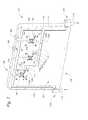
- FIG. 1shows one embodiment of an electronics module assembly utilizing spray nozzles.
- FIG. 2shows one embodiment of a module cover included in FIG. 1 utilizing spray nozzles.
- FIG. 3shows a side view of another embodiment of the disclosed electronics component assembly utilizing non-sprayed liquid flow.
- FIG. 4shows one embodiment of a module cover utilizing non-sprayed serial path liquid flow.
- FIG. 5shows a side view of another embodiment of the disclosed electronics component assembly utilizing spray nozzles.
- An electronics component assemblyconfigured to fluid cool high power density components.
- the disclosed electronics component assemblyincludes a module cover and a module.
- the module coverwhich is configured to make thermal contact with one or more heat-generating electronic components on the module, includes fluid passageways. The fluid passageways permit cooling fluid to flow through the module cover, thereby allowing the module cover to act as a heat sink.
- various cooling fluids in various statesmay be used, including liquids such as water or oils.
- a suitable fluidis 3M's FlourinertTM.
- fluid passagewaysmay be employed in a number of configurations and arrangements to accomplish the cooling of various components on the module.
- the electronics module assembly 100includes a module 106 having heat-generating electronic components 150 , 152 , 154 on a front surface 108 of the module 106 .
- the module 106includes a pair of circuit cards supported by a module frame, where heat generating components are disposed on a surface of the circuit cards.
- heat-generating electronic componentsinclude integrated circuits, microprocessors, or any electronic component that generates heat.
- the components 150 , 152 , 154are microprocessor chips.
- the electronics module assembly 100further includes a front module cover 104 and a top 102 for the module cover 104 .
- the material used for the module cover 104 and the top 102is not particularly limited, and is preferably a thermally conductive material, for example a metal such as aluminum, copper, etc.
- the module cover 104includes a fluid inlet 112 and a fluid outlet 114 .
- the inlet 112is provided on a first corner end 148 of the module cover 104 .
- the outlet 114is provided on a second corner end 149 of the module cover 104 .
- the module cover 104further includes a fluid passageway 110 .
- the inlet 112 and outlet 114are interconnected with the fluid passageway 110 .
- the fluid passageway 110is provided in a top surface 151 of the module cover 104 .
- FIG. 2shows the fluid passageway 110 as a recessed channel having a constant depth. However, it is to be realized that the depth of the fluid passageway 110 is not particularly limited, and in appropriate circumstances, the fluid passageway 110 can have variable depths.
- the fluid passageway 110leads to terminals 124 , 126 , 128 , which are trenched regions having depth and are interconnected with the fluid passageway 110 .
- the terminal 124provides a housing for nozzles 124 a , 124 b
- the terminal 126provides a housing for nozzles 126 a , 126 b
- the terminal 128provides a housing for nozzles 128 a , 128 b
- the nozzles 124 a , 124 b , 126 a , 126 b , 128 a , 128 bare configured to spray fluid into volumes 120 , 132 , 134 (shown in dashed lines).
- FIG. 1shows three terminals with each terminal having two nozzle openings. However, the number of terminals or nozzles used is not particularly limited.
- the terminals 124 , 126 , 128are interconnected with the volumes 120 , 132 , 134 , respectively through the nozzles 124 a , 124 b , 126 a , 126 b , 128 a , 128 b .
- the volumes 120 , 132 , 134are recessed cavities having depth, and are provided on a back surface (not shown) of the module cover 104 .
- the volumes 120 , 132 , 134have the same structure as that of volumes 166 , 168 , 172 of a back module cover 162 as shown in FIG. 1 .
- the volumes 166 , 168 , 172have respective bottom surfaces 166 a , 168 a , 172 a configured to make thermal contact with heat-generating components (not shown) on a back surface (not shown) of the module 106 .
- the volumes 120 , 132 , 134have bottom surfaces (not shown) configured to make thermal contact with the heat-generating components 150 , 152 , 154 .
- thermal contactmeans that there is actual physical contact between the heat generating components and the volumes. However, in appropriate circumstances, thermal contact could mean any arrangement where heat exchange occurs between the volumes and the heat generating components.
- FIGS. 1 and 2show three volumes and the shape of the volumes 120 , 132 , 134 as corresponding to the rectangular shapes of the heat-generating components 150 , 152 , 154 .
- the depth and shape of the volumes 120 , 132 , 134 and the number of volumes employedare not particularly limited.
- the module cover 104also includes ports 122 , 138 , 142 .
- the ports 122 , 138 , 142are provided within fluid passageways 111 , 113 , 115 , respectively, and allow interconnection between the volumes 120 , 132 , 134 and the respective fluid passageways 111 , 113 , 115 .
- the fluid passageways 111 , 113 , 115are interconnected with a fluid passageway 117 via a common fluid passageway 116 .
- the fluid passageway 117leads to and is interconnected with the fluid outlet 114 .
- the electronics module assembly 100is assembled by mating the module cover 104 with the module 106 such that the bottom surfaces of the volumes 120 , 132 , 134 are in thermal contact with top surfaces 150 a , 152 a , 154 a of the heat-generating components 150 , 152 , 154 , respectively.
- the top 102is provided on the module cover 104 so as to seal the module cover 104 and close the fluid passageways 110 , 111 , 113 , 115 , 117 .
- the top 102may be attached to the module cover 104 by any attachment method, for example, screws, brazing, soldering, etc.
- the assembled electronics module assembly 100has an assembled configuration similar to that of an electronics module assembly 300 shown in FIG. 3 .
- FIG. 3shows a front module cover 305 having a volume 321 where the cover 305 is mated with a module 309 having a heat generating component 320 such as a microprocessor chip.
- a top 311is provided on the module cover 305 .
- FIG. 3also shows a bottom surface 321 a of the volume 321 that is in direct thermal contact with a surface 320 a of the heat generating component 320 .
- fluidis pumped by a pump 170 from a fluid reservoir 160 to the inlet 112 of the module cover 104 .
- the fluidthen flows from the inlet 112 into the fluid passageway 110 .
- the fluidthen flows to the terminals 124 , 126 , 128 via a header passageway 118 .
- the header passageway 118provides simultaneous feeding of cooling fluid to the terminals.
- the fluidis sprayed into the volumes 120 , 132 , 134 through the respective nozzles 124 a , 124 b , 126 a , 126 b , 128 a , 128 b .
- the fluid that is sprayed into the volumes 120 , 132 , 134functions to cool the heat-generating components at the bottom surfaces of the volumes 120 , 132 , 134 by absorbing heat that is transferred to the bottom surfaces.
- a two-phase coolingis achieved, where the bottom surfaces are hot enough to vaporize the fluid.
- the fluid boiling pointis tailored to a predetermined temperature range.
- the electronics module assembly 100further includes a back module cover 162 .
- the configuration of the back module cover 162is similar to the front module cover 104 including the presence of fluid passageways similar to those of the front module cover 104 , the volumes 166 , 168 , 172 , terminals (not shown) with nozzles (not shown) and ports (not shown).
- the fluid passageways, the volumes 166 , 168 , 172 , the terminals, the nozzles and the ports of the back module cover 162are interconnected in a similar manner to that of the front module cover 104 .
- a parallel fluid passageway 163 for the cover 162is illustrated in dashed lines in FIG. 1 .
- the back module cover 162further includes a fluid inlet port 180 that is interconnected with the fluid passageways in the back module cover 162 .
- the inlet port 180is attached to a first end 192 of a first tube 174 , the first tube 174 being provided on a top side 188 of the back module cover 162 .
- a second end 194 of the first tube 174is configured to be attachable to a fluid outlet port 184 of the front module cover 104 .
- the outlet port 184is interconnected with the header passageway 118 in the front module cover 104 .
- cooling fluid in the heading passageway 118can flow to the module cover 162 via the outlet port 184 , the tube 174 and the inlet port 180 .
- the back module cover 162further includes a fluid outlet port 182 that is interconnected with the fluid passageways in the back module cover 162 .
- the outlet port 182is attached to a first end 190 of a second tube 176 , the second tube 176 being provided on the top side 188 of the back module cover 162 .
- a second end 196 of the second tube 176is configured to be attachable to a fluid port 186 of the front module cover 104 .
- the port 186is interconnected with the fluid passageway 117 in the front module cover 104 .
- the electronics module assembly 100is assembled by mating the back module cover 162 with the back surface of the module 106 such that the volumes 166 , 168 , 172 are in thermal contact with the heat-generating components (not shown) on the back surface of the module 106 .
- the second end 194 of the first tube 174is connected to the outlet port 184 and the second end 196 of the second tube 176 is connected to the inlet port 186 .
- the assembled electronics module assembly 100 including the back cover 162has an assembled configuration similar to that of the electronics module assembly 300 shown in FIG. 3 .
- FIG. 3further shows a back module cover 307 having a volume 323 , where the cover 307 is mated with the module 309 having a heat generating component 322 on a back surface 319 of the module 309 .
- a top 330is provided on the module cover 307 .
- FIG. 3also shows a bottom surface 323 a of the volume 323 that is in thermal contact with a surface 322 a of the heat generating component 322 .
- the front and back module covers 305 , 307can include fluid passageways (not shown) similar to those of the front module cover 104 and back module cover 162 shown in FIGS. 1 and 2 .
- the electronics module assembly 300further includes cooling fin assemblies 310 , 312 , respectively, disposed within the volumes 321 , 323 .
- the cooling fin assemblies 310 , 312include a number of cooling fins to increase the surface area for heat transfer.
- the cooling fin assemblies 310 , 312can be fixed in any suitable manner to the modules covers 305 , 307 , for example by brazing the assemblies to the volumes 321 , 323 and to the tops 311 , 330 . With this configuration, heat is transferred by conduction to the fins of the fin assemblies, and the fluid contacts the fin surfaces to transfer the heat to the fluid.
- FIG. 4shows another embodiment of a module cover 210 .
- the module cover 210includes a module fluid inlet 212 , a module fluid outlet 214 , volumes 223 , 225 , 227 , and fluid passageways 215 , 241 , 244 , 246 , 247 having a similar configuration to those shown in FIG. 2 .
- the module cover 210does not have nozzles and the flow path of the fluid passageways 215 , 241 , 244 , 246 is a serial flow path.
- the fluid passageway 215is interconnected with the module fluid inlet 212 and the volume 223
- the fluid passageway 241is interconnected with the volumes 223 , 225
- the fluid passageway 244is interconnected with the volumes 225 , 227
- the fluid passageway 246is interconnected with the volume 227 and an outlet port (not shown)
- fluid passageway 247is interconnected with an inlet port (not shown) and the module fluid outlet 214 .
- the module cover 210further includes cooling fin assemblies 229 , 231 , 233 disposed within the volumes 223 , 225 , 227 , respectively.
- the fluidfirst flows from the module inlet 212 into the fluid passageway 215 .
- the fluidthen flows over the cooling fin assembly 229 within the volume 223 .
- Once the fluid is drawn out by fluid pressure, the fluidthen flows into the fluid passageway 241 .
- the fluidthen flows over the cooling fin assemblies 231 , 233 within the respective volumes 225 , 227 in a similar manner.
- the fluidflows into the respective fluid passageways 244 and 246 .
- the fluidthen flows out through the outlet port.
- the fluidflows to the back module cover 162 and returns through the inlet port in a similar manner as described above.
- the fluidthen flows to the fluid passageway 247 , and then to the module fluid outlet 214 .
- the fluid passageways 215 , 241 , 244 , 246 , 247 described in FIG. 4illustrate a serial flow path for the cooling path as indicated above.
- the module cover 210may have a parallel flow path similar to the fluid passageways 110 , 111 , 113 , 115 , 117 described in FIG. 1 .
- the fluid passageways between the module fluid inlet 212 and the module fluid outlet 214are completely fluid filled.
- FIG. 5shows a side view of yet another embodiment of an assembled electronics module assembly 400 .
- the electronics module assembly 400includes a module cover 402 and a module 410 having a heat generating component 406 .
- the module cover 402includes fluid passageways (not shown) similar to the fluid passageways 110 , 111 , 113 , 115 , 117 shown in FIG. 2 .
- the module coverfurther includes a nozzle 404 .
- the nozzle 404is interconnected with the fluid passageways.
- the module cover 402also includes a wall 415 that is attached to a surface 402 a of the module cover 402 .
- the wall 415extends from the surface 402 a and is sealed to a surface 410 a of the module 410 .
- the wall 415surrounds the heat generating component 406 so as to create a sealed volume 408 .
- the nozzle 404is configured to spray fluid into the sealed volume 408 and directly onto the heat generating component 406 .
Landscapes
- Engineering & Computer Science (AREA)
- Microelectronics & Electronic Packaging (AREA)
- Physics & Mathematics (AREA)
- Condensed Matter Physics & Semiconductors (AREA)
- General Physics & Mathematics (AREA)
- Computer Hardware Design (AREA)
- Power Engineering (AREA)
- Thermal Sciences (AREA)
- Cooling Or The Like Of Semiconductors Or Solid State Devices (AREA)
- Cooling Or The Like Of Electrical Apparatus (AREA)
Abstract
Description
Claims (19)
Priority Applications (1)
| Application Number | Priority Date | Filing Date | Title |
|---|---|---|---|
| US12/330,819US8081478B1 (en) | 2008-12-09 | 2008-12-09 | Fluid cooled electronics module cover |
Applications Claiming Priority (1)
| Application Number | Priority Date | Filing Date | Title |
|---|---|---|---|
| US12/330,819US8081478B1 (en) | 2008-12-09 | 2008-12-09 | Fluid cooled electronics module cover |
Publications (1)
| Publication Number | Publication Date |
|---|---|
| US8081478B1true US8081478B1 (en) | 2011-12-20 |
Family
ID=45219234
Family Applications (1)
| Application Number | Title | Priority Date | Filing Date |
|---|---|---|---|
| US12/330,819Expired - Fee RelatedUS8081478B1 (en) | 2008-12-09 | 2008-12-09 | Fluid cooled electronics module cover |
Country Status (1)
| Country | Link |
|---|---|
| US (1) | US8081478B1 (en) |
Cited By (9)
| Publication number | Priority date | Publication date | Assignee | Title |
|---|---|---|---|---|
| WO2014027406A1 (en)* | 2012-08-15 | 2014-02-20 | 富士通株式会社 | Heat-receiving device, cooling device, and electronic device |
| US20140247555A1 (en)* | 2013-03-01 | 2014-09-04 | International Business Machines Corporation | Selective clamping of electronics card to coolant-cooled structure |
| US20150373871A1 (en)* | 2012-08-13 | 2015-12-24 | Huawei Technologies Co., Ltd. | Radio remote unit device and assembly thereof |
| US9357670B2 (en) | 2014-02-18 | 2016-05-31 | Lockheed Martin Corporation | Efficient heat transfer from conduction-cooled circuit cards |
| US9426931B2 (en) | 2014-02-07 | 2016-08-23 | Lockheed Martin Corporation | Fluid-flow-through cooling of circuit boards |
| US9960101B2 (en) | 2015-06-04 | 2018-05-01 | Raytheon Company | Micro-hoses for integrated circuit and device level cooling |
| US10188017B2 (en) | 2017-05-31 | 2019-01-22 | Microsoft Technology Licensing, Llc | Server cooling fluid inlet and pickup placement in submerged cooling enclosures |
| US10485137B2 (en) | 2017-03-01 | 2019-11-19 | Microsoft Technology Licensing, Llc | Cooling device for fluid submersion of electronics |
| US10697629B2 (en) | 2011-05-13 | 2020-06-30 | Rochester Institute Of Technology | Devices with an enhanced boiling surface with features directing bubble and liquid flow and methods thereof |
Citations (63)
| Publication number | Priority date | Publication date | Assignee | Title |
|---|---|---|---|---|
| US3921201A (en)* | 1972-01-22 | 1975-11-18 | Siemens Ag | Improved liquid cooled semiconductor disk arrangement |
| US4962444A (en)* | 1989-01-03 | 1990-10-09 | Sunstrand Corporation | Cold chassis for cooling electronic circuit components on an electronic board |
| US5023695A (en)* | 1988-05-09 | 1991-06-11 | Nec Corporation | Flat cooling structure of integrated circuit |
| US5050037A (en)* | 1984-01-26 | 1991-09-17 | Fujitsu Limited | Liquid-cooling module system for electronic circuit components |
| US5126829A (en)* | 1988-09-26 | 1992-06-30 | Hitachi, Ltd. | Cooling apparatus for electronic device |
| US5157588A (en)* | 1991-03-30 | 1992-10-20 | Samsung Electronics Co., Ltd. | Semiconductor package and manufacture thereof |
| US5159529A (en)* | 1991-05-15 | 1992-10-27 | International Business Machines Corporation | Composite liquid cooled plate for electronic equipment |
| US5177666A (en)* | 1991-10-24 | 1993-01-05 | Bland Timothy J | Cooling rack for electronic devices |
| US5177667A (en)* | 1991-10-25 | 1993-01-05 | International Business Machines Corporation | Thermal conduction module with integral impingement cooling |
| US5183104A (en)* | 1989-06-16 | 1993-02-02 | Digital Equipment Corporation | Closed-cycle expansion-valve impingement cooling system |
| US5239200A (en)* | 1991-08-21 | 1993-08-24 | International Business Machines Corporation | Apparatus for cooling integrated circuit chips |
| US5249100A (en)* | 1989-05-19 | 1993-09-28 | Hitachi, Ltd. | Electronic circuit device provided with a ceramic substrate having lead pins bonded thereto by solder |
| US5294830A (en)* | 1991-05-21 | 1994-03-15 | International Business Machines Corporation | Apparatus for indirect impingement cooling of integrated circuit chips |
| US5323292A (en)* | 1992-10-06 | 1994-06-21 | Hewlett-Packard Company | Integrated multi-chip module having a conformal chip/heat exchanger interface |
| US5463528A (en)* | 1992-01-22 | 1995-10-31 | Nec Corporation | Cooling structure for integrated circuits |
| US5675473A (en)* | 1996-02-23 | 1997-10-07 | Motorola, Inc. | Apparatus and method for shielding an electronic module from electromagnetic radiation |
| US5705850A (en)* | 1993-09-20 | 1998-01-06 | Hitachi, Ltd. | Semiconductor module |
| US5761035A (en)* | 1996-06-28 | 1998-06-02 | Motorola, Inc. | Circuit board apparatus and method for spray-cooling a circuit board |
| US5831824A (en)* | 1996-01-31 | 1998-11-03 | Motorola, Inc. | Apparatus for spray-cooling multiple electronic modules |
| US5841634A (en)* | 1997-03-12 | 1998-11-24 | Delco Electronics Corporation | Liquid-cooled baffle series/parallel heat sink |
| US5978220A (en)* | 1996-10-23 | 1999-11-02 | Asea Brown Boveri Ag | Liquid cooling device for a high-power semiconductor module |
| US6026565A (en)* | 1997-06-12 | 2000-02-22 | Harris Corporation | Housing for diverse cooling configuration printed circuit cards |
| US6082443A (en)* | 1997-02-13 | 2000-07-04 | The Furukawa Electric Co., Ltd. | Cooling device with heat pipe |
| US6236566B1 (en)* | 1998-02-23 | 2001-05-22 | Alstom Transport Sa | Cooling element for a power electronic device and power electronic device comprising same |
| US6292364B1 (en)* | 2000-04-28 | 2001-09-18 | Raytheon Company | Liquid spray cooled module |
| US6305463B1 (en)* | 1996-02-22 | 2001-10-23 | Silicon Graphics, Inc. | Air or liquid cooled computer module cold plate |
| US6351384B1 (en)* | 1999-08-11 | 2002-02-26 | Hitachi, Ltd. | Device and method for cooling multi-chip modules |
| US6366462B1 (en)* | 2000-07-18 | 2002-04-02 | International Business Machines Corporation | Electronic module with integral refrigerant evaporator assembly and control system therefore |
| US6392891B1 (en)* | 1999-07-02 | 2002-05-21 | Elta Electronics Industries Ltd. | Utilizing a convection cooled electronic circuit card for producing a conduction cooled electronic card module |
| US20020067598A1 (en)* | 2000-12-05 | 2002-06-06 | Sathe Ajit V. | Electronic assembly having a heat pipe that conducts heat from a semiconductor die |
| US6578626B1 (en)* | 2000-11-21 | 2003-06-17 | Thermal Corp. | Liquid cooled heat exchanger with enhanced flow |
| US6594149B2 (en)* | 2001-09-18 | 2003-07-15 | Hitachi, Ltd. | Liquid cooled circuit device |
| US20030178179A1 (en)* | 2002-02-23 | 2003-09-25 | Viktor Brost | Heat exchanger for electronic/electrical components |
| US6661658B2 (en)* | 2001-04-27 | 2003-12-09 | Aavid Thermalloy, Llc | Fluid-cooled heat sink for electronic components |
| US6662859B2 (en)* | 2001-11-28 | 2003-12-16 | Modine Manufacturing Company | Cooler for power electronics |
| US20040012914A1 (en)* | 2002-07-17 | 2004-01-22 | International Business Machines Corporation | Electronic device substrate assembly with multilayer impermeable barrier and method of making |
| US6721181B1 (en)* | 2002-09-27 | 2004-04-13 | Rockwell Automation Technologies, Inc. | Elongated heat sink for use in converter assemblies |
| US20040069451A1 (en)* | 2002-08-06 | 2004-04-15 | Meyer Michael T. | Apparatus for heat transfer and critical heat flux enhancement |
| US6882533B2 (en)* | 2001-02-22 | 2005-04-19 | Hewlett-Packard Development Company, L.P. | Thermal connector for cooling electronics |
| US6935412B2 (en)* | 2001-05-25 | 2005-08-30 | Agilent Technologies, Inc. | Cooler for electrical and/ or electronic components, linked to present cooling needs |
| US6942019B2 (en)* | 2002-03-25 | 2005-09-13 | Ltx Corporation | Apparatus and method for circuit board liquid cooling |
| US6986382B2 (en)* | 2002-11-01 | 2006-01-17 | Cooligy Inc. | Interwoven manifolds for pressure drop reduction in microchannel heat exchangers |
| US6988534B2 (en)* | 2002-11-01 | 2006-01-24 | Cooligy, Inc. | Method and apparatus for flexible fluid delivery for cooling desired hot spots in a heat producing device |
| US6992382B2 (en)* | 2003-12-29 | 2006-01-31 | Intel Corporation | Integrated micro channels and manifold/plenum using separate silicon or low-cost polycrystalline silicon |
| US7040383B2 (en)* | 2001-08-16 | 2006-05-09 | Nec Corporation | Telecommunication device including a housing having improved heat conductivity |
| US20060096738A1 (en)* | 2004-11-05 | 2006-05-11 | Aavid Thermalloy, Llc | Liquid cold plate heat exchanger |
| US20060232939A1 (en)* | 2000-04-19 | 2006-10-19 | Denso Corporation | Coolant cooled type semiconductor device |
| US20070091569A1 (en)* | 2005-10-25 | 2007-04-26 | International Business Machines Corporation | Cooling apparatus and method employing discrete cold plates disposed between a module enclosure and electronics components to be cooled |
| US20070097627A1 (en)* | 2005-10-28 | 2007-05-03 | Taylor Ralph S | Electronics assembly having multiple side cooling and method |
| US7262966B2 (en)* | 2004-05-28 | 2007-08-28 | Rhinol Tech Corp. | Heat sink modules for light and thin electronic equipment |
| US7352581B2 (en)* | 2005-06-30 | 2008-04-01 | Kabushiki Kaisha Toshiba | Cooling device and electronic apparatus |
| US7372697B2 (en)* | 2005-06-30 | 2008-05-13 | Kabushiki Kaisha Toshiba | Cooling device and electronic apparatus |
| US7417857B2 (en)* | 2003-10-31 | 2008-08-26 | Valeo Equipements Electriques Moteur | Power-electronic-cooling device |
| US20080264604A1 (en)* | 2007-04-24 | 2008-10-30 | International Business Machines Corporation | Cooling appartaus, cooled electronic module and methods of fabrication employing a manifold structure with interleaved coolant inlet and outlet passageways |
| US7450384B2 (en)* | 2006-07-06 | 2008-11-11 | Hybricon Corporation | Card cage with parallel flow paths having substantially similar lengths |
| US7460367B2 (en)* | 2007-03-05 | 2008-12-02 | Tracewell Systems, Inc. | Method and system for dissipating thermal energy from conduction-cooled circuit card assemblies which employ remote heat sinks and heat pipe technology |
| US20080315403A1 (en)* | 2004-11-12 | 2008-12-25 | Andry Paul S | Apparatus and methods for cooling semiconductor integrated circuit chip packages |
| US7486518B2 (en)* | 2005-06-30 | 2009-02-03 | Kabushiki Kaisha Toshiba | Cooling device and electronic apparatus |
| US20090040726A1 (en)* | 2007-08-09 | 2009-02-12 | Paul Hoffman | Vapor chamber structure and method for manufacturing the same |
| US20090219695A1 (en)* | 2008-02-28 | 2009-09-03 | Kabushiki Kaisha Toshiba | Electronic Device, Loop Heat Pipe and Cooling Device |
| US7602610B2 (en)* | 2006-11-28 | 2009-10-13 | Kabushiki Kaisha Toshiba | Electronic device |
| US7652885B2 (en)* | 2008-03-27 | 2010-01-26 | Kabushiki Kaisha Toshiba | Electronic device, cooling device and loop heat pipe |
| US7830664B2 (en)* | 2005-10-25 | 2010-11-09 | International Business Machines Corporation | Cooling apparatuses with discrete cold plates compliantly coupled between a common manifold and electronics components of an assembly to be cooled |
- 2008
- 2008-12-09USUS12/330,819patent/US8081478B1/ennot_activeExpired - Fee Related
Patent Citations (67)
| Publication number | Priority date | Publication date | Assignee | Title |
|---|---|---|---|---|
| US3921201A (en)* | 1972-01-22 | 1975-11-18 | Siemens Ag | Improved liquid cooled semiconductor disk arrangement |
| US5050037A (en)* | 1984-01-26 | 1991-09-17 | Fujitsu Limited | Liquid-cooling module system for electronic circuit components |
| US5023695A (en)* | 1988-05-09 | 1991-06-11 | Nec Corporation | Flat cooling structure of integrated circuit |
| US5126829A (en)* | 1988-09-26 | 1992-06-30 | Hitachi, Ltd. | Cooling apparatus for electronic device |
| US4962444A (en)* | 1989-01-03 | 1990-10-09 | Sunstrand Corporation | Cold chassis for cooling electronic circuit components on an electronic board |
| US5249100A (en)* | 1989-05-19 | 1993-09-28 | Hitachi, Ltd. | Electronic circuit device provided with a ceramic substrate having lead pins bonded thereto by solder |
| US5183104A (en)* | 1989-06-16 | 1993-02-02 | Digital Equipment Corporation | Closed-cycle expansion-valve impingement cooling system |
| US5157588A (en)* | 1991-03-30 | 1992-10-20 | Samsung Electronics Co., Ltd. | Semiconductor package and manufacture thereof |
| US5159529A (en)* | 1991-05-15 | 1992-10-27 | International Business Machines Corporation | Composite liquid cooled plate for electronic equipment |
| US5294830A (en)* | 1991-05-21 | 1994-03-15 | International Business Machines Corporation | Apparatus for indirect impingement cooling of integrated circuit chips |
| US5239200A (en)* | 1991-08-21 | 1993-08-24 | International Business Machines Corporation | Apparatus for cooling integrated circuit chips |
| US5177666A (en)* | 1991-10-24 | 1993-01-05 | Bland Timothy J | Cooling rack for electronic devices |
| US5177667A (en)* | 1991-10-25 | 1993-01-05 | International Business Machines Corporation | Thermal conduction module with integral impingement cooling |
| US5463528A (en)* | 1992-01-22 | 1995-10-31 | Nec Corporation | Cooling structure for integrated circuits |
| US5323292A (en)* | 1992-10-06 | 1994-06-21 | Hewlett-Packard Company | Integrated multi-chip module having a conformal chip/heat exchanger interface |
| US5705850A (en)* | 1993-09-20 | 1998-01-06 | Hitachi, Ltd. | Semiconductor module |
| US5831824A (en)* | 1996-01-31 | 1998-11-03 | Motorola, Inc. | Apparatus for spray-cooling multiple electronic modules |
| US6305463B1 (en)* | 1996-02-22 | 2001-10-23 | Silicon Graphics, Inc. | Air or liquid cooled computer module cold plate |
| US5675473A (en)* | 1996-02-23 | 1997-10-07 | Motorola, Inc. | Apparatus and method for shielding an electronic module from electromagnetic radiation |
| US5761035A (en)* | 1996-06-28 | 1998-06-02 | Motorola, Inc. | Circuit board apparatus and method for spray-cooling a circuit board |
| US5978220A (en)* | 1996-10-23 | 1999-11-02 | Asea Brown Boveri Ag | Liquid cooling device for a high-power semiconductor module |
| US6082443A (en)* | 1997-02-13 | 2000-07-04 | The Furukawa Electric Co., Ltd. | Cooling device with heat pipe |
| US5841634A (en)* | 1997-03-12 | 1998-11-24 | Delco Electronics Corporation | Liquid-cooled baffle series/parallel heat sink |
| US6026565A (en)* | 1997-06-12 | 2000-02-22 | Harris Corporation | Housing for diverse cooling configuration printed circuit cards |
| US6236566B1 (en)* | 1998-02-23 | 2001-05-22 | Alstom Transport Sa | Cooling element for a power electronic device and power electronic device comprising same |
| US6392891B1 (en)* | 1999-07-02 | 2002-05-21 | Elta Electronics Industries Ltd. | Utilizing a convection cooled electronic circuit card for producing a conduction cooled electronic card module |
| US6621706B2 (en)* | 1999-07-02 | 2003-09-16 | Elta Electronics Industries Ltd. | Utilizing a convection cooled electronic circuit card for producing a conduction cooled electronic card module |
| US6351384B1 (en)* | 1999-08-11 | 2002-02-26 | Hitachi, Ltd. | Device and method for cooling multi-chip modules |
| US20060232939A1 (en)* | 2000-04-19 | 2006-10-19 | Denso Corporation | Coolant cooled type semiconductor device |
| US6292364B1 (en)* | 2000-04-28 | 2001-09-18 | Raytheon Company | Liquid spray cooled module |
| US6366462B1 (en)* | 2000-07-18 | 2002-04-02 | International Business Machines Corporation | Electronic module with integral refrigerant evaporator assembly and control system therefore |
| US6578626B1 (en)* | 2000-11-21 | 2003-06-17 | Thermal Corp. | Liquid cooled heat exchanger with enhanced flow |
| US6719039B2 (en)* | 2000-11-21 | 2004-04-13 | Thermal Corp. | Liquid cooled heat exchanger with enhanced flow |
| US6535386B2 (en)* | 2000-12-05 | 2003-03-18 | Intel Corporation | Electronic assembly having a heat pipe that conducts heat from a semiconductor die |
| US20020067598A1 (en)* | 2000-12-05 | 2002-06-06 | Sathe Ajit V. | Electronic assembly having a heat pipe that conducts heat from a semiconductor die |
| US6882533B2 (en)* | 2001-02-22 | 2005-04-19 | Hewlett-Packard Development Company, L.P. | Thermal connector for cooling electronics |
| US6661658B2 (en)* | 2001-04-27 | 2003-12-09 | Aavid Thermalloy, Llc | Fluid-cooled heat sink for electronic components |
| US6935412B2 (en)* | 2001-05-25 | 2005-08-30 | Agilent Technologies, Inc. | Cooler for electrical and/ or electronic components, linked to present cooling needs |
| US7040383B2 (en)* | 2001-08-16 | 2006-05-09 | Nec Corporation | Telecommunication device including a housing having improved heat conductivity |
| US6594149B2 (en)* | 2001-09-18 | 2003-07-15 | Hitachi, Ltd. | Liquid cooled circuit device |
| US6662859B2 (en)* | 2001-11-28 | 2003-12-16 | Modine Manufacturing Company | Cooler for power electronics |
| US20030178179A1 (en)* | 2002-02-23 | 2003-09-25 | Viktor Brost | Heat exchanger for electronic/electrical components |
| US6942019B2 (en)* | 2002-03-25 | 2005-09-13 | Ltx Corporation | Apparatus and method for circuit board liquid cooling |
| US20040012914A1 (en)* | 2002-07-17 | 2004-01-22 | International Business Machines Corporation | Electronic device substrate assembly with multilayer impermeable barrier and method of making |
| US20040069451A1 (en)* | 2002-08-06 | 2004-04-15 | Meyer Michael T. | Apparatus for heat transfer and critical heat flux enhancement |
| US7035104B2 (en)* | 2002-08-06 | 2006-04-25 | Mudawar Thermal Systems Inc. | Apparatus for heat transfer and critical heat flux enhancement |
| US6721181B1 (en)* | 2002-09-27 | 2004-04-13 | Rockwell Automation Technologies, Inc. | Elongated heat sink for use in converter assemblies |
| US6986382B2 (en)* | 2002-11-01 | 2006-01-17 | Cooligy Inc. | Interwoven manifolds for pressure drop reduction in microchannel heat exchangers |
| US6988534B2 (en)* | 2002-11-01 | 2006-01-24 | Cooligy, Inc. | Method and apparatus for flexible fluid delivery for cooling desired hot spots in a heat producing device |
| US7417857B2 (en)* | 2003-10-31 | 2008-08-26 | Valeo Equipements Electriques Moteur | Power-electronic-cooling device |
| US6992382B2 (en)* | 2003-12-29 | 2006-01-31 | Intel Corporation | Integrated micro channels and manifold/plenum using separate silicon or low-cost polycrystalline silicon |
| US7262966B2 (en)* | 2004-05-28 | 2007-08-28 | Rhinol Tech Corp. | Heat sink modules for light and thin electronic equipment |
| US20060096738A1 (en)* | 2004-11-05 | 2006-05-11 | Aavid Thermalloy, Llc | Liquid cold plate heat exchanger |
| US20080315403A1 (en)* | 2004-11-12 | 2008-12-25 | Andry Paul S | Apparatus and methods for cooling semiconductor integrated circuit chip packages |
| US7372697B2 (en)* | 2005-06-30 | 2008-05-13 | Kabushiki Kaisha Toshiba | Cooling device and electronic apparatus |
| US7352581B2 (en)* | 2005-06-30 | 2008-04-01 | Kabushiki Kaisha Toshiba | Cooling device and electronic apparatus |
| US7486518B2 (en)* | 2005-06-30 | 2009-02-03 | Kabushiki Kaisha Toshiba | Cooling device and electronic apparatus |
| US20070091569A1 (en)* | 2005-10-25 | 2007-04-26 | International Business Machines Corporation | Cooling apparatus and method employing discrete cold plates disposed between a module enclosure and electronics components to be cooled |
| US7830664B2 (en)* | 2005-10-25 | 2010-11-09 | International Business Machines Corporation | Cooling apparatuses with discrete cold plates compliantly coupled between a common manifold and electronics components of an assembly to be cooled |
| US20070097627A1 (en)* | 2005-10-28 | 2007-05-03 | Taylor Ralph S | Electronics assembly having multiple side cooling and method |
| US7450384B2 (en)* | 2006-07-06 | 2008-11-11 | Hybricon Corporation | Card cage with parallel flow paths having substantially similar lengths |
| US7602610B2 (en)* | 2006-11-28 | 2009-10-13 | Kabushiki Kaisha Toshiba | Electronic device |
| US7460367B2 (en)* | 2007-03-05 | 2008-12-02 | Tracewell Systems, Inc. | Method and system for dissipating thermal energy from conduction-cooled circuit card assemblies which employ remote heat sinks and heat pipe technology |
| US20080264604A1 (en)* | 2007-04-24 | 2008-10-30 | International Business Machines Corporation | Cooling appartaus, cooled electronic module and methods of fabrication employing a manifold structure with interleaved coolant inlet and outlet passageways |
| US20090040726A1 (en)* | 2007-08-09 | 2009-02-12 | Paul Hoffman | Vapor chamber structure and method for manufacturing the same |
| US20090219695A1 (en)* | 2008-02-28 | 2009-09-03 | Kabushiki Kaisha Toshiba | Electronic Device, Loop Heat Pipe and Cooling Device |
| US7652885B2 (en)* | 2008-03-27 | 2010-01-26 | Kabushiki Kaisha Toshiba | Electronic device, cooling device and loop heat pipe |
Cited By (18)
| Publication number | Priority date | Publication date | Assignee | Title |
|---|---|---|---|---|
| US11598518B2 (en) | 2011-05-13 | 2023-03-07 | Rochester Institute Of Technology | Devices with an enhanced boiling surface with features directing bubble and liquid flow and methods thereof |
| US10697629B2 (en) | 2011-05-13 | 2020-06-30 | Rochester Institute Of Technology | Devices with an enhanced boiling surface with features directing bubble and liquid flow and methods thereof |
| US20150373871A1 (en)* | 2012-08-13 | 2015-12-24 | Huawei Technologies Co., Ltd. | Radio remote unit device and assembly thereof |
| US9642284B2 (en)* | 2012-08-13 | 2017-05-02 | Huawei Technologies Co., Ltd. | Radio remote unit device and assembly thereof |
| WO2014027406A1 (en)* | 2012-08-15 | 2014-02-20 | 富士通株式会社 | Heat-receiving device, cooling device, and electronic device |
| US9681591B2 (en) | 2012-08-15 | 2017-06-13 | Fujitsu Limited | Heat-receiving device, cooling device, and electronic device |
| JPWO2014027406A1 (en)* | 2012-08-15 | 2016-07-25 | 富士通株式会社 | Heat receiving device |
| US9591787B2 (en) | 2013-03-01 | 2017-03-07 | International Business Machines Corporation | Selective clamping of electronics card to coolant-cooled structure |
| US9258925B2 (en) | 2013-03-01 | 2016-02-09 | International Business Machines Corporation | Selective clamping of electronics card to coolant-cooled structure |
| US9144178B2 (en)* | 2013-03-01 | 2015-09-22 | International Business Machines Corporation | Selective clamping of electronics card to coolant-cooled structure |
| US20140247555A1 (en)* | 2013-03-01 | 2014-09-04 | International Business Machines Corporation | Selective clamping of electronics card to coolant-cooled structure |
| US9426931B2 (en) | 2014-02-07 | 2016-08-23 | Lockheed Martin Corporation | Fluid-flow-through cooling of circuit boards |
| US10362713B2 (en) | 2014-02-07 | 2019-07-23 | Lockheed Martin Corporation | Process for making an apparatus with fluid-flow-through cooling of circuit boards |
| US10548243B2 (en) | 2014-02-07 | 2020-01-28 | Lockheed Martin Corporation | Process for installing an insert for fluid-flow-through cooling of circuit boards |
| US9357670B2 (en) | 2014-02-18 | 2016-05-31 | Lockheed Martin Corporation | Efficient heat transfer from conduction-cooled circuit cards |
| US9960101B2 (en) | 2015-06-04 | 2018-05-01 | Raytheon Company | Micro-hoses for integrated circuit and device level cooling |
| US10485137B2 (en) | 2017-03-01 | 2019-11-19 | Microsoft Technology Licensing, Llc | Cooling device for fluid submersion of electronics |
| US10188017B2 (en) | 2017-05-31 | 2019-01-22 | Microsoft Technology Licensing, Llc | Server cooling fluid inlet and pickup placement in submerged cooling enclosures |
Similar Documents
| Publication | Publication Date | Title |
|---|---|---|
| US8081478B1 (en) | Fluid cooled electronics module cover | |
| CN118891598B (en) | Active cooling heat sink cover for computer processor and processor assembly | |
| EP4190137B1 (en) | Cooling device for cooling components of a circuit board | |
| EP1381083B1 (en) | Apparatus for removing heat from a circuit | |
| JPS6336695Y2 (en) | ||
| EP2359670B1 (en) | Electronic module with pump-enhanced, dielectric fluid immersion-cooling | |
| US8157001B2 (en) | Integrated liquid to air conduction module | |
| US6058010A (en) | Enhanced test head liquid cooled cold plate | |
| US7764494B2 (en) | Liquid cooled module | |
| US6377453B1 (en) | Field replaceable module with enhanced thermal interface | |
| CN114303037A (en) | Re-entry fluid cold plate | |
| US7454920B2 (en) | Method and apparatus for moisture control within a phased array | |
| US10362712B2 (en) | Heat receiver, cooling unit, and electronic device | |
| TW202334598A (en) | Liquid cooling device and liquid cooling system having the liquid cooling device | |
| EP3575919A1 (en) | Dlc block for use in electronic and electric components | |
| US12178019B2 (en) | Coolant system for a busbar assembly | |
| US12029013B2 (en) | Cooling plate with coaxial fluid port | |
| CN216566086U (en) | Liquid-cooled heat dissipation device, liquid-cooled heat dissipation system and electronic device | |
| US11924996B2 (en) | Liquid-cooling devices, and systems, to cool multi-chip modules | |
| KR102308872B1 (en) | System for cooling semiconductor component, method for manufacturing the same, and semiconductor package having the same | |
| TWI530249B (en) | Hybrid heat sink assembly | |
| US20250040110A1 (en) | Battery disconnect unit and drive system | |
| KR102232902B1 (en) | Electronic equipment device having cooling module and electronic equipment device assembly | |
| CN111403365B (en) | Intelligent power module | |
| JP6724613B2 (en) | Semiconductor device |
Legal Events
| Date | Code | Title | Description |
|---|---|---|---|
| AS | Assignment | Owner name:LOCKHEED MARTIN CORPORATION, MARYLAND Free format text:ASSIGNMENT OF ASSIGNORS INTEREST;ASSIGNORS:DREXLER, GREGORY M.;GRETTE, MELISSA A.;THORSON, KEVIN J.;SIGNING DATES FROM 20090209 TO 20090210;REEL/FRAME:022265/0065 | |
| ZAAA | Notice of allowance and fees due | Free format text:ORIGINAL CODE: NOA | |
| ZAAB | Notice of allowance mailed | Free format text:ORIGINAL CODE: MN/=. | |
| STCF | Information on status: patent grant | Free format text:PATENTED CASE | |
| FPAY | Fee payment | Year of fee payment:4 | |
| MAFP | Maintenance fee payment | Free format text:PAYMENT OF MAINTENANCE FEE, 8TH YEAR, LARGE ENTITY (ORIGINAL EVENT CODE: M1552); ENTITY STATUS OF PATENT OWNER: LARGE ENTITY Year of fee payment:8 | |
| FEPP | Fee payment procedure | Free format text:MAINTENANCE FEE REMINDER MAILED (ORIGINAL EVENT CODE: REM.); ENTITY STATUS OF PATENT OWNER: LARGE ENTITY | |
| LAPS | Lapse for failure to pay maintenance fees | Free format text:PATENT EXPIRED FOR FAILURE TO PAY MAINTENANCE FEES (ORIGINAL EVENT CODE: EXP.); ENTITY STATUS OF PATENT OWNER: LARGE ENTITY | |
| STCH | Information on status: patent discontinuation | Free format text:PATENT EXPIRED DUE TO NONPAYMENT OF MAINTENANCE FEES UNDER 37 CFR 1.362 | |
| FP | Lapsed due to failure to pay maintenance fee | Effective date:20231220 |