US8080895B1 - Energy generation from compressed fluids - Google Patents
Energy generation from compressed fluidsDownload PDFInfo
- Publication number
- US8080895B1 US8080895B1US12/189,535US18953508AUS8080895B1US 8080895 B1US8080895 B1US 8080895B1US 18953508 AUS18953508 AUS 18953508AUS 8080895 B1US8080895 B1US 8080895B1
- Authority
- US
- United States
- Prior art keywords
- working fluid
- energy
- fluid
- module
- power module
- Prior art date
- Legal status (The legal status is an assumption and is not a legal conclusion. Google has not performed a legal analysis and makes no representation as to the accuracy of the status listed.)
- Expired - Fee Related, expires
Links
- 239000012530fluidSubstances0.000titleclaimsabstractdescription262
- 238000000034methodMethods0.000claimsabstractdescription39
- 230000033001locomotionEffects0.000claimsdescription41
- XLYOFNOQVPJJNP-UHFFFAOYSA-NwaterSubstancesOXLYOFNOQVPJJNP-UHFFFAOYSA-N0.000claimsdescription40
- 230000006835compressionEffects0.000claimsdescription22
- 238000007906compressionMethods0.000claimsdescription22
- 238000006243chemical reactionMethods0.000claimsdescription7
- 239000000203mixtureSubstances0.000claimsdescription7
- 230000000712assemblyEffects0.000claimsdescription5
- 238000000429assemblyMethods0.000claimsdescription5
- 229910052761rare earth metalInorganic materials0.000claimsdescription2
- 150000002910rare earth metalsChemical class0.000claimsdescription2
- 239000007789gasSubstances0.000abstractdescription12
- VNWKTOKETHGBQD-UHFFFAOYSA-NmethaneChemical compoundCVNWKTOKETHGBQD-UHFFFAOYSA-N0.000abstractdescription6
- CURLTUGMZLYLDI-UHFFFAOYSA-NCarbon dioxideChemical compoundO=C=OCURLTUGMZLYLDI-UHFFFAOYSA-N0.000abstractdescription5
- QGZKDVFQNNGYKY-UHFFFAOYSA-NAmmoniaChemical compoundNQGZKDVFQNNGYKY-UHFFFAOYSA-N0.000abstractdescription4
- IJGRMHOSHXDMSA-UHFFFAOYSA-NAtomic nitrogenChemical compoundN#NIJGRMHOSHXDMSA-UHFFFAOYSA-N0.000abstractdescription4
- ATUOYWHBWRKTHZ-UHFFFAOYSA-NPropaneChemical compoundCCCATUOYWHBWRKTHZ-UHFFFAOYSA-N0.000abstractdescription4
- 229910002092carbon dioxideInorganic materials0.000abstractdescription3
- 239000001569carbon dioxideSubstances0.000abstractdescription3
- 239000007788liquidSubstances0.000abstractdescription3
- OTMSDBZUPAUEDD-UHFFFAOYSA-NEthaneChemical compoundCCOTMSDBZUPAUEDD-UHFFFAOYSA-N0.000abstractdescription2
- 229910021529ammoniaInorganic materials0.000abstractdescription2
- QVGXLLKOCUKJST-UHFFFAOYSA-Natomic oxygenChemical compound[O]QVGXLLKOCUKJST-UHFFFAOYSA-N0.000abstractdescription2
- 239000001273butaneSubstances0.000abstractdescription2
- 239000001257hydrogenSubstances0.000abstractdescription2
- 229910052739hydrogenInorganic materials0.000abstractdescription2
- 125000004435hydrogen atomChemical class[H]*0.000abstractdescription2
- IJDNQMDRQITEOD-UHFFFAOYSA-Nn-butaneChemical compoundCCCCIJDNQMDRQITEOD-UHFFFAOYSA-N0.000abstractdescription2
- OFBQJSOFQDEBGM-UHFFFAOYSA-Nn-pentaneNatural productsCCCCCOFBQJSOFQDEBGM-UHFFFAOYSA-N0.000abstractdescription2
- 229910052757nitrogenInorganic materials0.000abstractdescription2
- 239000001301oxygenSubstances0.000abstractdescription2
- 229910052760oxygenInorganic materials0.000abstractdescription2
- 239000001294propaneSubstances0.000abstractdescription2
- 239000003345natural gasSubstances0.000abstract1
- 239000003570airSubstances0.000description62
- 239000000463materialSubstances0.000description19
- 238000000926separation methodMethods0.000description17
- 230000005291magnetic effectEffects0.000description12
- 230000005611electricityEffects0.000description10
- 239000000919ceramicSubstances0.000description7
- 238000003780insertionMethods0.000description7
- 230000037431insertionEffects0.000description7
- 229910001092metal group alloyInorganic materials0.000description7
- 229910052751metalInorganic materials0.000description6
- 239000002184metalSubstances0.000description6
- 150000002739metalsChemical class0.000description6
- 229920003023plasticPolymers0.000description5
- 239000004033plasticSubstances0.000description5
- 229920004142LEXAN™Polymers0.000description4
- -1and equivalents)Substances0.000description4
- 229910000838Al alloyInorganic materials0.000description3
- RYGMFSIKBFXOCR-UHFFFAOYSA-NCopperChemical compound[Cu]RYGMFSIKBFXOCR-UHFFFAOYSA-N0.000description3
- 229920002430Fibre-reinforced plasticPolymers0.000description3
- 229920005479Lucite®Polymers0.000description3
- 229920000079Memory foamPolymers0.000description3
- 229920005372Plexiglas®Polymers0.000description3
- 239000011151fibre-reinforced plasticSubstances0.000description3
- 239000008210memory foamSubstances0.000description3
- 239000004926polymethyl methacrylateSubstances0.000description3
- 238000004804windingMethods0.000description3
- 241000218691CupressaceaeSpecies0.000description2
- UQSXHKLRYXJYBZ-UHFFFAOYSA-NIron oxideChemical compound[Fe]=OUQSXHKLRYXJYBZ-UHFFFAOYSA-N0.000description2
- 229920005439Perspex®Polymers0.000description2
- 239000000853adhesiveSubstances0.000description2
- 230000001070adhesive effectEffects0.000description2
- 239000012080ambient airSubstances0.000description2
- 230000008901benefitEffects0.000description2
- 230000005540biological transmissionEffects0.000description2
- 239000004020conductorSubstances0.000description2
- 238000010586diagramMethods0.000description2
- 229920001971elastomerPolymers0.000description2
- 239000000835fiberSubstances0.000description2
- 239000011521glassSubstances0.000description2
- 229910001095light aluminium alloyInorganic materials0.000description2
- 239000003949liquefied natural gasSubstances0.000description2
- 229920003229poly(methyl methacrylate)Polymers0.000description2
- 239000004431polycarbonate resinSubstances0.000description2
- 229920005668polycarbonate resinPolymers0.000description2
- 229920000642polymerPolymers0.000description2
- 239000012858resilient materialSubstances0.000description2
- 239000011347resinSubstances0.000description2
- 229920005989resinPolymers0.000description2
- 239000005060rubberSubstances0.000description2
- 238000007493shaping processMethods0.000description2
- 229910000859α-FeInorganic materials0.000description2
- 229910000851Alloy steelInorganic materials0.000description1
- 229910001369BrassInorganic materials0.000description1
- OKTJSMMVPCPJKN-UHFFFAOYSA-NCarbonChemical compound[C]OKTJSMMVPCPJKN-UHFFFAOYSA-N0.000description1
- 241000158500Platanus racemosaSpecies0.000description1
- QJVKUMXDEUEQLH-UHFFFAOYSA-N[B].[Fe].[Nd]Chemical compound[B].[Fe].[Nd]QJVKUMXDEUEQLH-UHFFFAOYSA-N0.000description1
- 229910045601alloyInorganic materials0.000description1
- 239000000956alloySubstances0.000description1
- 229910000828alnicoInorganic materials0.000description1
- 229910052782aluminiumInorganic materials0.000description1
- XAGFODPZIPBFFR-UHFFFAOYSA-NaluminiumChemical compound[Al]XAGFODPZIPBFFR-UHFFFAOYSA-N0.000description1
- 238000007664blowingMethods0.000description1
- 239000010951brassSubstances0.000description1
- 229910052799carbonInorganic materials0.000description1
- 230000008859changeEffects0.000description1
- KPLQYGBQNPPQGA-UHFFFAOYSA-Ncobalt samariumChemical compound[Co].[Sm]KPLQYGBQNPPQGA-UHFFFAOYSA-N0.000description1
- 229910052802copperInorganic materials0.000description1
- 239000010949copperSubstances0.000description1
- 230000008878couplingEffects0.000description1
- 238000010168coupling processMethods0.000description1
- 238000005859coupling reactionMethods0.000description1
- 230000006837decompressionEffects0.000description1
- 239000011152fibreglassSubstances0.000description1
- 230000004907fluxEffects0.000description1
- 239000006260foamSubstances0.000description1
- 229920001821foam rubberPolymers0.000description1
- 239000011810insulating materialSubstances0.000description1
- 229920000126latexPolymers0.000description1
- 239000004816latexSubstances0.000description1
- 230000009347mechanical transmissionEffects0.000description1
- 238000000465mouldingMethods0.000description1
- 229910001172neodymium magnetInorganic materials0.000description1
- AJCDFVKYMIUXCR-UHFFFAOYSA-Noxobarium;oxo(oxoferriooxy)ironChemical compound[Ba]=O.O=[Fe]O[Fe]=O.O=[Fe]O[Fe]=O.O=[Fe]O[Fe]=O.O=[Fe]O[Fe]=O.O=[Fe]O[Fe]=O.O=[Fe]O[Fe]=OAJCDFVKYMIUXCR-UHFFFAOYSA-N0.000description1
- 238000012856packingMethods0.000description1
- 230000035699permeabilityEffects0.000description1
- 229920001568phenolic resinPolymers0.000description1
- 239000005011phenolic resinSubstances0.000description1
- 229920000728polyesterPolymers0.000description1
- 229920000098polyolefinPolymers0.000description1
- 239000000047productSubstances0.000description1
- 229910000938samarium–cobalt magnetInorganic materials0.000description1
- 239000007787solidSubstances0.000description1
- 239000010935stainless steelSubstances0.000description1
- 229910001220stainless steelInorganic materials0.000description1
- 229910052712strontiumInorganic materials0.000description1
- CIOAGBVUUVVLOB-UHFFFAOYSA-Nstrontium atomChemical compound[Sr]CIOAGBVUUVVLOB-UHFFFAOYSA-N0.000description1
- 239000000126substanceSubstances0.000description1
- 239000013589supplementSubstances0.000description1
- 239000011800void materialSubstances0.000description1
Images


Classifications
- H—ELECTRICITY
- H02—GENERATION; CONVERSION OR DISTRIBUTION OF ELECTRIC POWER
- H02K—DYNAMO-ELECTRIC MACHINES
- H02K15/00—Processes or apparatus specially adapted for manufacturing, assembling, maintaining or repairing of dynamo-electric machines
- H02K15/02—Processes or apparatus specially adapted for manufacturing, assembling, maintaining or repairing of dynamo-electric machines of stator or rotor bodies
- H02K15/03—Processes or apparatus specially adapted for manufacturing, assembling, maintaining or repairing of dynamo-electric machines of stator or rotor bodies having permanent magnets
- F—MECHANICAL ENGINEERING; LIGHTING; HEATING; WEAPONS; BLASTING
- F03—MACHINES OR ENGINES FOR LIQUIDS; WIND, SPRING, OR WEIGHT MOTORS; PRODUCING MECHANICAL POWER OR A REACTIVE PROPULSIVE THRUST, NOT OTHERWISE PROVIDED FOR
- F03B—MACHINES OR ENGINES FOR LIQUIDS
- F03B11/00—Parts or details not provided for in, or of interest apart from, the preceding groups, e.g. wear-protection couplings, between turbine and generator
- F03B11/002—Injecting air or other fluid
- F—MECHANICAL ENGINEERING; LIGHTING; HEATING; WEAPONS; BLASTING
- F03—MACHINES OR ENGINES FOR LIQUIDS; WIND, SPRING, OR WEIGHT MOTORS; PRODUCING MECHANICAL POWER OR A REACTIVE PROPULSIVE THRUST, NOT OTHERWISE PROVIDED FOR
- F03B—MACHINES OR ENGINES FOR LIQUIDS
- F03B13/00—Adaptations of machines or engines for special use; Combinations of machines or engines with driving or driven apparatus; Power stations or aggregates
- H—ELECTRICITY
- H02—GENERATION; CONVERSION OR DISTRIBUTION OF ELECTRIC POWER
- H02K—DYNAMO-ELECTRIC MACHINES
- H02K7/00—Arrangements for handling mechanical energy structurally associated with dynamo-electric machines, e.g. structural association with mechanical driving motors or auxiliary dynamo-electric machines
- H02K7/18—Structural association of electric generators with mechanical driving motors, e.g. with turbines
- H02K7/1807—Rotary generators
- H02K7/1853—Rotary generators driven by intermittent forces
- Y—GENERAL TAGGING OF NEW TECHNOLOGICAL DEVELOPMENTS; GENERAL TAGGING OF CROSS-SECTIONAL TECHNOLOGIES SPANNING OVER SEVERAL SECTIONS OF THE IPC; TECHNICAL SUBJECTS COVERED BY FORMER USPC CROSS-REFERENCE ART COLLECTIONS [XRACs] AND DIGESTS
- Y02—TECHNOLOGIES OR APPLICATIONS FOR MITIGATION OR ADAPTATION AGAINST CLIMATE CHANGE
- Y02E—REDUCTION OF GREENHOUSE GAS [GHG] EMISSIONS, RELATED TO ENERGY GENERATION, TRANSMISSION OR DISTRIBUTION
- Y02E10/00—Energy generation through renewable energy sources
- Y02E10/20—Hydro energy
Definitions
- This inventionrelates to a method and system of generating energy from compressed fluids, and in particular, to providing a method and system to compress and store a fluid and create electrical energy or other types of useful energy.
- Windmillsfor example, have been built in many areas of the country where the wind frequently blows. As the wind blows against the windmills, rotational power is created and then coupled through various types of transmissions to drive generators to generate electricity. This energy is often used to supplement energy produced by utility power plants.
- the present inventioncan be implemented in numerous ways, such as by a method or a system. Four aspects of the invention are described below.
- a first aspect of the inventionis directed to a method to produce power from the compression of a working fluid.
- the methodincludes converting the motion of a fluid into a rotational energy, wherein the rotational energy is coupled to a compressor module with at least one working fluid and a compressor to compress the at least one working fluid; compressing the at least one working fluid in the compressor module into a pressurized working fluid, wherein the pressurized working fluid is coupled to at least one storage module for storage of the pressurized working fluid; releasing a portion of the pressurized working fluid through at least one power module, wherein the at least one power module can generate a usable form of energy; and generating a usable form of energy from the at least one power module by a motion of the portion of the pressurized working fluid.
- a second aspect of the inventionis directed to a method to produce power from the compression of a working fluid.
- the methodincludes converting the motion of a fluid into a rotational energy, wherein the rotational energy is coupled to a compressor module with at least one working fluid and a compressor to compress the at least one working fluid; compressing the at least one working fluid in the compressor module into a pressurized working fluid, wherein the pressurized working fluid is coupled to at least one storage module for storage of the pressurized working fluid; releasing a portion of the pressurized working fluid through at least one power module, wherein the at least one power module can generate a usable form of energy; and generating a usable form of energy from the at least one power module by a motion of the portion of the pressurized working fluid.
- a third aspect of the inventionis directed to a system to produce power from the compression of a working fluid.
- the systemincludes a compressor module with at least one working fluid and a compressor to compress the at least one working fluid into a pressurized working fluid by utilizing the motion of a fluid; a storage module for storage of the pressurized working fluid produced by the compressor module; and a power module to generate a usable form of energy by releasing a portion of the pressurized working fluid through the at least one power module.
- a fourth aspect of the inventionis directed to a system to produce power from the compression of a working fluid.
- the systemincludes a compressor module with at least one working fluid and a compressor to compress the at least one working fluid into a pressurized working fluid by utilizing the motion of a fluid; a storage module for storage of the pressurized working fluid produced by the compressor module; and a power module to generate a usable form of energy by releasing a portion of the pressurized working fluid through the at least one power module.
- FIG. 1illustrates a front view of a power module disk, in accordance with one embodiment of the invention.
- FIG. 2illustrates a side cross-sectional view of a power module disk, in accordance with one embodiment of the invention.
- FIG. 3illustrates a front view of a housing for a power module disk, in accordance with one embodiment of the invention.
- FIG. 4illustrates a side cross-sectional view of multiple EMF coil assemblies in proximity to a housing for a power module disk, in accordance with one embodiment of the invention.
- FIG. 5illustrates an EMF coil assembly, in accordance with one embodiment of the invention.
- FIG. 6illustrates multiple EMF coil assemblies in proximity to both sides of a power module disk, in accordance with one embodiment of the invention.
- FIG. 7illustrates a multiple power module arrangement, in accordance with one embodiment of the invention.
- FIG. 8illustrates a compressor module including a floor module to supply a compressed working fluid, in accordance with one embodiment of the invention.
- FIG. 9illustrates a compressor module including a floor module to supply a compressed working fluid, in accordance with one embodiment of the invention.
- FIG. 10illustrates a plurality of floor modules coupled together to provide a compressed fluid, in accordance with one embodiment of the invention.
- FIG. 11illustrates a general compression system to provide a pressurized working fluid, in accordance with one embodiment of the invention.
- FIG. 12illustrates a wind power system to provide a pressurized working fluid, in accordance with one embodiment of the invention.
- FIG. 13illustrates a flowchart of a method to produce energy from the compression of at least one working fluid, in accordance with one embodiment of the invention.
- FIG. 14illustrates a flowchart of a method to produce energy from the compression of at least one working fluid, in accordance with one embodiment of the invention.
- FIG. 15illustrates a flowchart of a method to fabricate a power module, in accordance with one embodiment of the invention.
- FIG. 16illustrates a flowchart of a method to fabricate a power module, in accordance with one embodiment of the invention.
- FIG. 17illustrates a turbine without magnets, in accordance with one embodiment of the invention.
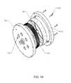
- FIG. 18illustrates an exploded view of a housing for a turbine disk, in accordance with one embodiment of the invention.
- FIG. 19illustrates another exploded view of a housing for a turbine disk, in accordance with one embodiment of the invention.
- FIG. 20illustrates a turbine and flywheel power module, in accordance with one embodiment of the invention.
- FIG. 21illustrates a double turbine power module, in accordance with one embodiment of the invention.
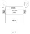
- FIG. 22illustrates a compressor module, in accordance with one embodiment of the invention.
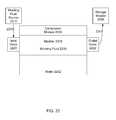
- FIG. 23illustrates a compressor module, in accordance with one embodiment of the invention.
- FIG. 24illustrates a number of compressors in a body of water, in accordance with one embodiment of the invention.
- FIG. 25illustrates a number of compressors in a body of water, in accordance with one embodiment of the invention.
- Embodiments of the inventioncan be constructed from commercially available components.
- different materialscould be used for fabricating the various modules (e.g., the turbines, and housings, and other components) including but not exclusively including: various plastics, rubbers, resins (e.g., phenolic resins and equivalents), fiber-reinforced polymers (e.g., using fibers of various compositions, such as glass, and equivalents), ceramics, and metals (e.g., aluminum alloys, such as 6061 aircraft aluminum, and equivalent metals and metal alloys).
- various plasticse.g., rubbers, resins (e.g., phenolic resins and equivalents), fiber-reinforced polymers (e.g., using fibers of various compositions, such as glass, and equivalents), ceramics, and metals (e.g., aluminum alloys, such as 6061 aircraft aluminum, and equivalent metals and metal alloys).
- different materialscould be used for the piping, including but not exclusively including: various plastics, rubbers, resins, fiber-reinforced polymers, ceramics, metals, metal alloys, or other equivalent manmade materials.
- generators or permanent magnetscould be selectively utilized in a power module for energy generation, depending on the application, such as aluminum-nickel-cobalt (Alnico), and rare-earth magnets, such as samarium-cobalt, and neodymium-iron-boron (as known as NeFeB or NIB), strontium, iron oxide, or barium ferrite ceramic magnets, and equivalent high magnetic strength magnets.
- High magnetic strength plastic magnetscould be used in an alternative embodiment.
- Such magnetsare available from various commercial suppliers (e.g., McMaster Carr, with corporate headquarters in Atlanta, Ga.; Stanford Magnets Company, with corporate headquarters in Aliso Viejo, Calif.; K&J Magnetics, Inc., with corporate headquarters in Jamison, Pa.; and other suppliers).
- one fluidis used to operate a compressor module, and a second fluid is used as the working fluid to ultimately flow into the power module.
- a working fluidSeveral possible materials could be utilized for the working fluid, including but not exclusively including: atmospheric air, steam, oxygen, hydrogen, nitrogen, various types of commercially available Freons, carbon dioxide (CO 2 ), methane, ethane, propane, butane, liquefied natural gas (LNG), ammonia, any mixture of the above, or other fluids that can be compressed.
- One embodiment of the inventionuses the same fluid (e.g., air) for the fluid and the working fluid, and would typically release the working fluid to the atmosphere.
- Other embodiments of the invention that use a working fluid other than airwould typically utilize a closed system to recycle the working fluid and avoid release of the working fluid to the atmosphere.
- One embodiment of the inventionprovides a system for generating useful mechanical power, which can be used by itself to generate chemical energy or compress gases, or connected to one or more generators to produce either AC or DC electricity. Some embodiments of the invention provide apparatus or systems specifically useful for generating electricity to supply power for local use or connection into an electrical grid for distribution elsewhere.
- Windmilla device to convert the kinetic energy of a moving fluid into a rotational energy of a relatively low RPM, which can be used to operate a compressor to compress a working fluid into a pressurized working fluid.
- Turbinea device to convert the kinetic energy of a moving fluid or a moving working fluid into a rotational energy of a relatively high RPM, which can be used to operate a compressor to compress a working fluid into a pressurized working fluid, or used in other cases to operate a generator to generate power.
- Pressure regulatora device to maintain a specific range of pressurized working fluid.
- Voltage regulatora device to maintain a specific range of electrical voltage in an electrical circuit.
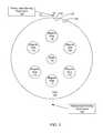
- FIG. 1illustrates a front view of a power module disk, in accordance with one embodiment of the invention.
- This front viewincludes a flat disk 102 , having a shaft 104 (or in an alternative embodiment a shaft hole for insertion of a shaft) for the later insertion of a bearing (not shown).
- the disk 102also has a plurality of magnet holes 106 , 108 , 110 , 112 , 114 , and 116 for the later placement of permanent magnets (not shown).
- the disk 102also has a plurality of substantially semicircular grooves 132 and 134 and separations 142 fabricated along the entire circumference of the disk 102 (the substantially semicircular grooves 132 and 134 and separation 142 between the grooves 132 and 134 are shown greatly enlarged, and would be fabricated around substantially the entire circumference of the disk 102 , but the semicircular grooves of the entire circumference of the disk are not shown for the sake of clarity).
- One or more pressurized working fluid outlets 150(two are shown for clarity, but any number of such outlets can be used) provide a working fluid 152 with kinetic energy to rotate the disk 102 .
- the substantially semicircular arcs 132 and 134would be major arcs (i.e., more than 180 degrees of arc) of circles or substantially circular ellipses. These substantially semicircular arcs 132 and 134 help improve the transfer of the kinetic energy of the working fluid 152 to the disk 102 , and increase the rotational energy of the disk 102 .
- the substantially semicircular grooves 132 and 134have a radius of approximately 0.025 inches (0.635 millimeter) and the separation 142 has a width of approximately 0.026 inches (0.66 millimeter).
- other embodiments of the inventioncan have either larger dimensions or smaller dimensions for the substantially semicircular grooves 132 and 134 and separation 142 between them. And other embodiments of the invention can use grooves that are major or minor circular arcs or other substantially circular shaped arcs fabricated on the circumference of the disk 102 .
- the disk 102is fabricated from an aluminum alloy (e.g., aircraft aluminum 6061, or an equivalent), but the disk 102 could alternatively be fabricated completely or partially from other materials capable of withstanding the mechanical forces created during operation (e.g., various fiber-reinforced polymers (e.g., using fibers of various compositions, such as carbon, glass or equivalents), ceramics, and other metals besides aluminum alloys, such as steel alloys).
- an aluminum alloye.g., aircraft aluminum 6061, or an equivalent
- the disk 102could alternatively be fabricated completely or partially from other materials capable of withstanding the mechanical forces created during operation (e.g., various fiber-reinforced polymers (e.g., using fibers of various compositions, such as carbon, glass or equivalents), ceramics, and other metals besides aluminum alloys, such as steel alloys).
- the disk 102could be fabricated from a solid flat disk having the holes 104 , 106 , 108 , 110 , 112 , 114 , and 116 drilled, or in an alternative embodiment the disk 102 could be molded (e.g., from a metal alloy or equivalent) with the holes 106 , 108 , 110 , 112 , 114 , and 116 already placed.
- the number of magnet holescould range from two or more holes, depending on the diameter of the disk 102 , the diameter of the magnet holes, and the desired energy output from the disk.
- magnet holes 106 , 108 , 110 , 112 , 114 , and 116would also affect the rotational velocity of the magnets (not shown).
- circular magnet holesare illustrated in this embodiment, alternative embodiments of the invention could use magnet holes having other polygon shapes (e.g., rectangles).
- the holestypically are chosen to substantially match the selected shapes of the magnets to be inserted in the holes.
- Various types of commercially available adhesivescan be used to hold the magnets in the magnet holes, if necessary.
- the disk 102when fully assembled, would be set in rotational motion by the kinetic energy of a pressurized working fluid 152 released and directed from one or more pressurized working fluid outlets 150 .
- the angle of incidence between the tangent of the circumference of the disk 102 and the directed motion of the pressurized working fluid 152is approximately 37 degrees to increase the efficiency of power transfer from the kinetic energy of the pressurized working fluid 152 to the disk 102 . In other embodiments of the invention, other angles can be used.
- the pressurized working fluid outlets 152have an internal diameter equal to or greater than 0.040 inches (1 millimeter), and in various embodiments there are one to twelve pressurized working fluid outlets 152 evenly distributed around the circumference on the disk 102 to direct working fluid at the disk 102 .
- the dimensions of the substantially semicircular grooves (for example, substantially semicircular grooves 132 and 134 ) and separations (for example, separation 142 ) on the circumference of the disk 102can also be optimized to capture the kinetic energy of the working fluid 152 .
- the width of the separation 142is substantially equal to the radius of the substantially semicircular grooves 132 and 134 on the circumference of the disk 102 to increase the efficiency of power transfer from the kinetic energy of the pressurized working fluid 152 to the disk 102 .
- other relative dimensions of the radii and separationscan be used, and/or a plurality of radii and separations can be used around the circumference of the disk 102 .
- the final steady state rotational velocity of the disk 102will correspond to a high revolution per minute (RPM), typically ranging from 5,000 to 60,000 RPM in various embodiments, so ceramic bearings or air bearings (not shown) in shaft 104 should be selected to sustain the high RPM for reliable operation.
- RPMrevolution per minute
- the diameter of the disk 102typically ranges from 2 inches (5.08 centimeters) to 10 inches (25.4 centimeters), but the diameter of the disk 102 can be larger or smaller in other embodiments of the invention.
- the thickness (width) of the circumference rim of the disk 102is 1.5 inches (3.81 centimeters), but the thickness can be less or more than 1.5 inches in other embodiments.
- the thickness of the disk 102is not uniform and can be recessed or expanded compared to the thickness of the disk 102 at the circumference rim of the disk 102 .
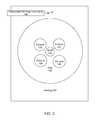
- FIG. 2illustrates a side cross-sectional view of a power module disk, in accordance with one embodiment of the invention.
- FIG. 2is not drawn to scale.
- This view of disk 102illustrates two of the magnet holes 106 and 112 , with permanent magnets 202 and 204 inserted in the magnet holes 106 and 112 , respectively.
- the diameters of the permanent magnets 202 and 204would actually fit very tightly within the diameters of the magnet holes 106 and 112 , but a looser fit is shown here only for clarity.
- 16 pound ( ⁇ 7.25 kilograms) pull centered magnets with dimensions of 0.875 inch by 0.25 inch ( ⁇ 2.187 centimeter by 0.625 centimeter)would be used.
- cylindrical (i.e., rod) magnetsare used in some embodiments, alternative embodiments of the invention can use block magnets having rectangular shapes, or even arbitrary polygon shapes.
- Shaft 104is also shown and would need to have a diameter sufficient to accommodate a bearing (not shown).
- R26 ceramic bearingswould be used, available from various commercial suppliers (e.g., US Bearings and Drives, with corporate headquarters in Vancouver, Wash.; Bartlett Bearing Corporation, with corporate headquarters in Philadelphia, Pa.; and other suppliers).
- FIG. 3illustrates a front view of a housing for a power module disk, in accordance with one embodiment of the invention. For clarity, FIG. 3 is not drawn to scale.
- This front viewincludes an X-ray view of the housing 302 , and shows a pressurized working fluid outlet 150 to provide pressurized working fluid 152 to the circumference of the disk 102 inside the housing 302 .
- This viewalso shows the shaft 104 for the later insertion of a bearing (not shown).
- Exhaust holes 122 , 124 , 126 and 128are also shown, and these would be used to route the pressurized working fluid after utilization to either a storage module (not shown) in a closed-loop system, or to atmosphere in the case of an open-loop system (e.g., using atmospheric air for the pressurized working fluid).
- the number of exhaust holescould be one, two, three, four or any number of exhaust holes, placed anywhere on the housing in various embodiments of the invention, as many and as large as necessary to completely the exhaust the working fluid after the energy is extracted.
- the housing 302is fabricated from one or more sheets of a polycarbonate resin, such as Lexan®, which is a material commercially available in sheets having a thickness typically ranging from 0.75 millimeter to 12 millimeters. In various embodiments, the thickness of the housing 302 would typically range from 5 millimeters to 25 millimeters.
- Lexan®is commercially available from General Electric Plastics, with corporate headquarters in Pittsfield, Mass.
- Alternative embodimentscould be fabricated with one or more sheets of other strong, non-conducting materials, e.g., polymers such as polymethyl methacrylate (e.g., Plexiglas®, Lucite®, Perspex®) or an equivalent material. Such materials are commercially available from Professional Plastics, Inc., with corporate headquarters in Fullerton, Calif.; Lucite International Ltd., with corporate headquarters in Victoria, United Kingdom; Arkema, with corporate headquarters in Paris, France; and other suppliers.
- Polymethyl methacrylatee.g., Plexiglas®
- FIG. 4illustrates multiple EMF coil assemblies in proximity to a power module disk, in accordance with one embodiment of the invention.
- Housing 302shows a side cross-sectional view of the disk 102 , showing the magnet holes 106 and 112 , magnets 206 and 212 , and the shaft 104 , as shown in FIG. 2 .
- EMF coils 304 , 306 , 308 , 310 , 312 , and 314In proximity to one side of housing 302 are EMF coils 304 , 306 , 308 , 310 , 312 , and 314 , with corresponding connection leads 324 , 326 , 328 , 330 , 332 , and 334 to the respective EMF coils.
- ferrite coresare used in some or all of the EMF coils.
- EMF coils and ferrite coresare available from various commercial suppliers (e.g., Coleman Magnetics, with corporate headquarters in Vacaville, Calif.; McMaster Carr, with corporate headquarters in Atlanta, Ga.; and other suppliers).
- nano-crystalline metal alloy cores(with relatively low energy losses at alternating magnetic frequencies up to 100,000 Hertz) are used in some or all of the EMF coils to minimize energy losses in the cores experiencing higher frequency AC magnetic fields.
- Nano-crystalline metal alloy coresare available from various commercial suppliers (e.g., Magnetic Metals, with corporate headquarters in Camden, N.J.; and other suppliers).
- FIG. 5illustrates an EMF coil assembly, in accordance with one embodiment of the invention.
- FIG. 5is not drawn to scale.
- magnet 206is shown in disk 102 .
- the air gap 450could range from 0.2 centimeter to 1.7 centimeters, and the coil separators 402 and 404 could be fabricated from a flat sheet of Plexiglas®, Lexan®, or from another equivalent insulating material.
- the EMF coil 304may provide an alternating current voltage ranging from 2 volts to hundreds of volts, depending on the rotational velocity of the magnet 206 , the distance of the EMF coil 304 from the magnet 206 , and the number of windings on the EMF coil 304 .
- a high permeability alloyis inserted inside the EMF coil 304 .
- the coilsmay have any appropriate number of windings to achieve any desired output voltage and current.
- the wiring of the coilsshould include wire with a thickness gauge sufficient to handle large induced currents, depending on the load, the transformer ratio, the number of windings on the coils, and the rate of change of the magnetic flux inside the coils.
- 18 gauge copper wireis used to fabricate the coils.
- 20 gauge copper wireis used to fabricate the coils.
- Other gauges of wire or flat ribbons of copper or other conducting metals or metal alloyscan be used in other embodiments of the invention.
- a step-up transformercan be used to achieve a higher voltage and lower current from the output of the coils.
- An appropriate transformercan also be used to adjust the output impedance of the power module.
- Other equivalent power conversioncan be achieved, but at some loss in electrical power conversion efficiency. Since the frequency of the electricity generated will typically be far in excess of 60 Hz, any transformer used should be designed to have low energy loss at high frequency operation. Voltage regulators are also used in some embodiments of the invention.
- Transformers and voltage regulators for various embodimentsare available from multiple commercial suppliers (e.g., Coleman Magnetics, with corporate headquarters in Vacaville, Calif.; and McMaster Carr, with corporate headquarters in Atlanta, Ga.; Jameco Electronic Components & Computer Products, with corporate headquarters in Belmont, Calif.; and other suppliers).
- the primary coilsproduce 87 volts RMS with 25 amperes of current
- the secondary coilsproduce 230 volts RMS with 18 amperes of current per phase
- the stationary coilsproduce 230 volts RMS per phase.
- a phase convertercan combine three phases into one phase and can produce 120 volts RMS at 48 amperes at 60 Hertz. Phase converters (sometimes also called inverters) are available from multiple commercial suppliers (e.g., AC Delco, with corporate headquarters in Detroit, Mich.; Yamaha Motor Corporation USA, with corporate headquarters in Cypress, Calif.; and American Honda Power Equipment Division, with corporate headquarters in Alpharetta, Ga.; and other suppliers).
- FIG. 6illustrates multiple EMF coil assemblies in proximity to both sides of a power module disk, in accordance with one embodiment of the invention.
- Housing 302shows a side cross-sectional view of the disk 102 , showing the magnet holes 106 and 112 , magnets 206 and 212 , and the shaft 104 , as shown in FIGS. 2 and 4 .
- EMF coils 304 , 306 , 308 , 310 , 312 , and 314In proximity to one side of housing 302 are EMF coils 304 , 306 , 308 , 310 , 312 , and 314 , with corresponding connection leads 324 , 326 , 328 , 330 , 332 , and 334 to the respective EMF coils.
- EMF coils 504 , 506 , 508 , 510 , 512 , and 514In proximity to the other side of housing 302 are EMF coils 504 , 506 , 508 , 510 , 512 , and 514 , with corresponding connection leads 524 , 526 , 528 , 530 , 532 , and 534 to the respective EMF coils.
- the placement and the number of EMF coilsare arbitrary and can be selected for the needs of a specific application.
- three EMF coilscan be placed in a triangular configuration on at least one side of the housing 302 to generate three phases of AC voltage from the rotating magnetic fields generated by the rotation of the disk 102 and the magnets assembled on the disk 102 .
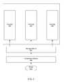
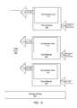
- FIG. 7illustrates a multiple power module arrangement, in accordance with one embodiment of the invention. For clarity, FIG. 7 is not drawn to scale.
- Each housing 302contains a power module disk (not shown), and each power module disk is coupled to a pressurized working fluid provided by storage module 604 .
- Compressor module 606provides a pressurized working fluid to storage module 604 , wherein the energy to pressurize the working fluid is derived from the motion of a fluid 608 .
- the working fluid and the fluidare the same fluid.
- the working fluid and the fluidare different fluids.
- the storage module 604is a stainless steel air tank.
- the compressor module 606is a windmill and the fluid and working fluid are a gas (e.g., air). In another embodiment, the compressor module 606 utilizes one or more floor modules to provide a pressurized working fluid, such as air.
- a gase.g., air
- the compressor module 606utilizes one or more floor modules to provide a pressurized working fluid, such as air.
- One embodiment of the inventionuses a 25 PSI (pounds per square inch) and 6 CFM (cubic feet per minute) compressor windmill to compress air.
- Such windmillsare commercially available from Koenders Windmills, Inc., with corporate headquarters in Englefeld, Saskatchewan, Canada; Superior Windmills, Inc., with corporate headquarters in Regina, Saskatchewan, Canada; and other suppliers.
- the packing density of the power module disks and their housingsis determined by many factors, such as the working fluid used, the physical dimensions of the disks and housings of the power modules, and the physical dimensions of the EMF coils and their associated materials.
- center-tapped EMF coilsallow closely packed multiple disk arrangements, with a disk on each end of the coil to induce electromagnetic energy in the coil by the rotation of the magnetic fields of the disks.
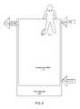
- FIG. 8illustrates a compressor module including a floor module to supply a compressed working fluid (e.g., air, or an equivalent gas), in accordance with one embodiment of the invention.
- a compressed working fluide.g., air, or an equivalent gas
- FIG. 8is not drawn to scale, and shows in dotted lines at least one person 800 .
- Floor module 702includes a compressor unit 712 and a plurality of uni-directional fluid valves—in this embodiment, this floor module has three uni-directional valves 706 , 708 , and 710 .
- This floor module 702may be on the surface of the floor, or it may be placed underneath a surface floor covering (e.g., a rug, linoleum, tile, or an equivalent).
- the compressor unit 712is made from two sheets (or one sheet) of memory foam, with collapsible elliptical or circular cross-sectioned tubing (but not expandable tubing) glued between the two sheets of memory foam.
- another type of resilient material that will return to its original shapee.g., a generic open cell polyolefin, open cell polyester, open cell latex, foam rubber, or an equivalent material
- the valves 706 , 708 , and 710are air valves, and the working fluid is air.
- the inner diameter of the tubingis between 0.0625 inch (0.1588 centimeter) and 0.125 inch (0.3175 centimeter), and the sheets above and below the tubing are at least 0.125 inch (0.3175 centimeter) thick.
- the valves 706 , 708 , and 710are fluid valves for a gas or liquid working fluid other than air.
- FIG. 8An external weight or force (e.g., at least one person 800 is shown in dotted lines that walks on top on the floor module 702 is shown in FIG. 8 , which is not drawn to scale) would press on the compressor unit 712 (e.g., a network of hollow tubing with one or two layers of resilient foam, or an equivalent material) in the floor module 702 .
- the floor module 702has a compressor unit 712 (e.g., an internal void) coupled with a first valve 706 coupled to either a pipe or another floor module (not shown).
- the floor module 702also has a second valve 708 coupled to the compressor unit 712 to accept fluid in one direction supplied by another floor module (not shown) to replenish the fluid expelled out of valve 706 .
- the floor module 702also has a third valve 710 coupled to the compressor unit 712 to accept fluid in one direction supplied by the ambient environment (for example, the atmosphere, which is not shown) to replenish the compressor unit 712 .
- the fluid handled by all three valvesis air
- the third valve 710is merely an air valve with access to ambient air.
- First valve 706 , second valve 708 , and third valve 710are all uni-directional, allowing fluid flow in only one direction.
- the valvescan be opened in one direction by a pressure differential as little as 0.01 PSI, but can resist being opened in the opposite direction by pressure differentials up to 175 PSI.
- Fluid valves and couplingscan be obtained from various commercial suppliers (e.g., Royal Brass, Inc., with corporate headquarters in San Jose, Calif.; Parker Hannifin, with corporate headquarters in Cleveland, Ohio; W.W. Grainger, with corporate headquarters in Lake Forest, Ill.; and other suppliers).
- FIG. 9illustrates a compressor module including a floor module to supply a compressed working fluid (e.g., air, or an equivalent gas), in accordance with one embodiment of the invention.
- a compressed working fluide.g., air, or an equivalent gas
- FIG. 9is not drawn to scale, and it shows in dotted lines at least one person 800 that walks on top of the floor module 702 .
- Floor module 702includes a compressor unit 712 and a plurality of uni-directional fluid valves—in this embodiment, this floor module 702 has two uni-directional valves 706 and 710 .
- This floor module 702may be on the surface of the floor, or it may be placed under a floor covering (e.g., a rug, linoleum, tile, or an equivalent).
- valves 706 and 710are air valves, and valve 710 is merely an air valve connected to ambient air in order to replenish the air removed by means of valve 706 from the compressor unit 712 .
- valves 706 and 710are fluid valves for working fluid gas or liquid fluid other than air. In the case of working fluids other than air, the working fluid would typically be utilized in a closed-loop system for re-use.
- FIG. 10illustrates a plurality of floor modules coupled together to provide a compressed fluid (e.g., air, or an equivalent gas), in accordance with one embodiment of the invention.
- a compressed fluide.g., air, or an equivalent gas
- the floor modules 802are coupled together to provide a compressed fluid (e.g., air, or an equivalent gas) that can be compressed by the weight of people and objects moving over the plurality of floor modules 802 .
- These floor modules 802may be on the surface of the floor, or be placed under a floor covering (e.g., a rug, linoleum, tile, or an equivalent).
- floor modules 802are interconnected by a network of feed pipes 902 to route the fluid (e.g., air, or an equivalent gas) in one direction into a storage module 904 (e.g., an air tank) that supplies a compressed fluid (e.g., air, or equivalent gas) to a power module (not shown).
- a network of feed pipes 902to route the fluid (e.g., air, or an equivalent gas) in one direction into a storage module 904 (e.g., an air tank) that supplies a compressed fluid (e.g., air, or equivalent gas) to a power module (not shown).
- a storage module 904e.g., an air tank
- a compressed fluide.g., air, or equivalent gas
- FIG. 11illustrates a general compression system to provide a pressurized working fluid, in accordance with one embodiment of the invention.
- Fluid 1002is an input to a compressor module 1004 , which can be powered by any type of natural energy (e.g., a windmill, a plurality of floor modules, or an equivalent natural energy source) to pressurize a working fluid for storage in storage module 1006 .
- Storage module 1006supplies pressurized working fluid to power module 1008 for movement of the working fluid to a lower pressure state and to thereby generate electricity or another type of usable energy.
- the lower pressure statemay simply be an exhaust to the atmosphere in the case of a system using air as a working fluid.
- the lower pressure statemay be another lower pressure region in a closed loop system in the case of using some other type of fluid used as a working fluid, such as Freon or other gases or fluids that must be recycled.
- a feedback connector 1010to take the working fluid from the power module 1008 back to the compressor module 1004 for re-pressurization.
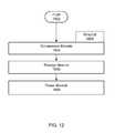
- FIG. 12illustrates a wind power system to provide a pressurized working fluid, in accordance with one embodiment of the invention.
- Fluid 1002is an input to a compressor module 1004 , which is powered by at least one windmill 1005 to pressurize a working fluid for storage in storage module 1006 .
- Storage module 1006supplies pressurized working fluid to power module 1008 for movement of the working fluid to a lower pressure state and to thereby generate electricity or another type of usable energy.
- the lower pressure statemay simply be an exhaust to the atmosphere in the case of a system using air as a working fluid.
- the lower pressure statemay be another lower pressure region in a closed loop system in the case of using some other type of fluid used as a working fluid, such as Freon or other fluids previously listed as alternative working fluids that must be recycled.
- FIG. 13illustrates a flowchart of a method to produce energy from the compression of at least one working fluid, according to one embodiment of the invention.
- the sequencestarts in operation 1302 .
- Operation 1304includes compressing at least one working fluid in a compressor module to produce a pressurized working fluid.
- Operation 1306is next and includes storing the pressurized working fluid in at least one storage module.
- Operation 1308is next and includes releasing a portion of the pressurized working fluid from the at least one storage module through at least one power module.
- Operation 1310is next and includes generating a usable form of energy from the at least one power module by a motion of the portion of the pressurized working fluid.
- the methodends in operation 1312 .
- FIG. 14illustrates a flowchart of a method to produce energy from the compression of at least one working fluid, according to one embodiment of the invention.
- the sequencestarts in operation 1402 .
- Operation 1404includes converting the motion of a fluid into a rotational energy, wherein the rotational energy is coupled to a compressor module with at least one working fluid.
- Operation 1406includes compressing the at least one working fluid in a compressor module to produce a pressurized working fluid.
- Operation 1408is next and includes storing the pressurized working fluid in at least one storage module.
- Operation 1410is next and includes releasing a portion of the pressurized working fluid from at the at least one storage module through at least one power module.
- Operation 1412is next and includes generating a usable form of energy from the at least one power module by a motion of the portion of the pressurized working fluid.
- the methodends in operation 1414 .
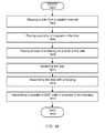
- FIG. 15illustrates a flowchart of a method to fabricate a power module, according to one embodiment of the invention.
- the sequencestarts in operation 1502 .
- Operation 1504includes shaping (e.g., molding, stamping, cutting, or an equivalent) a disk from a strong material (e.g., aluminum, a metal alloy, a glass-reinforced plastic, or an equivalent).
- Operation 1506includes cutting a plurality of holes in the disk for a plurality of magnets.
- Operation 1508includes cutting a plurality of substantially semicircular grooves on the circumference of the disk.
- the substantially semicircular groovesmay have a circular or nearly circular shape or another shape that is relatively effective at converting the tangential linear motion of a fluid on the circumference of the disk into a rotational energy of the disk.
- Operation 1512includes placing a plurality of magnets in a plurality of holes in the disk.
- Operation 1514includes inserting at least one bearing on the shaft of the disk.
- Operation 1516includes balancing the disk.
- Operation 1518includes assembling the disk with a housing.
- Operation 1520includes assembling a plurality of EMF coils in proximity to the housing. The method ends in operation 1522 .
- FIG. 16illustrates a flowchart of a method to fabricate a power module, according to one embodiment of the invention.
- the sequencestarts in operation 1602 .
- Operation 1604includes shaping a disk from a material (e.g., a disk material previously listed above).
- Operation 1606includes placing a plurality of magnets in a plurality of holes in the disk.
- Operation 1608includes inserting at least one bearing on the shaft of the disk.
- Operation 1610includes balancing the disk.
- Operation 1612includes assembling the disk with a housing.
- Operation 1614includes assembling a plurality of EMF coils in proximity to the housing. The method ends in operation 1616 .
- the kinetic energy of a working fluidis applied to a disk in order to produce the torque to turn an electrical generator, instead of using the disk itself as an electrical generator.
- a working fluide.g., air
- PSIpounds per square inch of pressure
- Such electrical generatorsare available from multiple commercial suppliers (e.g., AC Delco, with corporate headquarters in Detroit, Mich.; Yamaha Motor Corporation USA, with corporate headquarters in Cypress, Calif.; and American Honda Power Equipment Division, with corporate headquarters in Alpharetta, Ga.; and other suppliers).
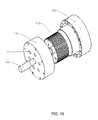
- FIG. 17illustrates a turbine without magnets, in accordance with one embodiment of the invention.
- FIG. 17is not drawn to scale.
- This front viewincludes a flat disk 1702 , having a shaft 104 (or in an alternative embodiment a shaft hole for insertion of a shaft) for the later insertion of a bearing (not shown).
- the disk 1702has a plurality of substantially semicircular grooves 132 and 134 and separations 142 fabricated along the entire circumference of the disk 102 (the substantially semicircular grooves 132 and 134 and separation 142 between the grooves 132 and 134 are shown greatly enlarged, and would be fabricated around the entire circumference of the disk 1702 , but the semicircular grooves of the entire circumference of the disk are not shown for the sake of clarity).
- One or more pressurized working fluid outlets 150(two are shown for clarity, but any number of such outlets can be used) provide a working fluid 152 with kinetic energy to rotate the disk 102 .
- the substantially semicircular arcs 132 and 134would be major arcs (i.e., more than 180 degrees of arc) of circles or substantially circular ellipses. These substantially semicircular arcs 132 and 134 help improve the transfer of the kinetic energy of the working fluid 152 to the disk 1702 , and increase the rotational energy of the disk 1702 .
- the substantially semicircular grooves 132 and 134have a radius of approximately 0.025 inches (0.635 millimeters) and the separation 142 has a width of approximately 0.026 inches (0.66 millimeters).
- other embodiments of the inventioncan have either larger dimensions or smaller dimensions for the substantially semicircular grooves 132 and 134 and separation 142 .
- other embodiments of the inventioncan use grooves that are major or minor circular arcs or other substantially circular shaped arcs fabricated on the circumference of the disk 1702 .
- the disk 1702when fully assembled, would be set in rotational motion by the kinetic energy of a pressurized working fluid 152 released and directed from one or more pressurized working fluid outlets 150 .
- the angle of incidence between the tangent of the circumference of the disk 1702 and the directed motion of the pressurized working fluid 152is approximately 37 degrees to increase the efficiency of power transfer from the kinetic energy of the pressurized working fluid 152 to the disk 102 . In other embodiments of the invention, other angles can be used.
- the dimensions of the substantially semicircular grooves (for example, substantially semicircular grooves 132 and 134 ) and separations (for example, separation 142 ) on the circumference of the disk 102can also be optimized to capture the kinetic energy of the working fluid 152 .
- the width of the separation 142is substantially equal to the radius of the substantially semicircular grooves 132 and 134 on the circumference of the disk 102 to increase the efficiency of energy transfer from the kinetic energy of the pressurized working fluid 152 to the rotational energy of the disk 1702 .
- other relative dimensions of the radii and separationscan be used.
- the final steady state rotational velocity of the disk 1702will correspond to a high revolution per minute (RPM), typically ranging from 5,000 to 60,000 RPM in various embodiments, so ceramic bearings or air bearings (not shown) in shaft 104 should be selected to sustain the high RPM for reliable operation.
- RPMrevolution per minute
- the diameter of the disk 1702would typically range from 2 inches (5.08 centimeters) to 10 inches (25.4 centimeters), but could be larger or smaller in other embodiments of the invention.
- the thickness (width) of the disk 102is 1.5 inches (3.81 centimeters), but the disk thickness can be less or more than 1.5 inches in other embodiments.
- FIG. 18illustrates an exploded view of a housing for a turbine disk, in accordance with one embodiment of the invention.
- FIG. 18is not drawn to scale.
- This viewincludes the housing 302 (split in separate parts) that encloses the sides and circumference of the disk 1702 .
- This viewalso shows the shaft 104 for the later insertion of a bearing (not shown).
- Six exhaust holes 122are also shown on the housing 302 , and these would be used to route the pressurized working fluid after utilization to either a storage module (not shown) in a closed-loop system, or to atmosphere in the case of an open-loop system (e.g., using atmospheric air for the pressurized working fluid).
- the number of exhaust holescan be any number of exhaust holes, placed anywhere on the housing in various embodiments of the invention, as many and as large as necessary to completely the exhaust the working fluid after the energy is extracted.
- the housing 302is fabricated from one or more sheets of a polycarbonate resin, such as Lexan®, which is a material commercially available in sheets having a thickness typically ranging from 0.75 millimeter to 12 millimeters. In various embodiments, the thickness of the housing 302 would typically range from 5 millimeters to 25 millimeters.
- Alternative embodimentscould be fabricated with one or more sheets of other strong, non-conducting materials, e.g., polymers such as polymethyl methacrylate (e.g., Plexiglas®, Lucite®, Perspex®) or an equivalent material. Some commercial suppliers of these materials have already been listed previously.
- polymerssuch as polymethyl methacrylate (e.g., Plexiglas®, Lucite®, Perspex®) or an equivalent material.
- FIG. 19illustrates an exploded view of a housing for a turbine disk, in accordance with one embodiment of the invention.
- FIG. 19is not drawn to scale.
- This viewincludes the housing 302 that encloses sides and circumference of the disk 1702 , gasket 1804 , and the bolts 1930 that will be used to hold the parts of the housing 302 together.
- a very strong adhesiveis used to assemble the housing instead of a gasket and bolts.
- This viewalso shows the shaft 104 for the later insertion of a bearing (not shown).
- Six exhaust holes 122are also shown on the housing 302 , and these would be used to route the pressurized working fluid after utilization to either a storage module (not shown) in a closed-loop system, or to atmosphere in the case of an open-loop system (e.g., using atmospheric air for the pressurized working fluid).
- FIG. 20illustrates a turbine and flywheel power module, in accordance with one embodiment of the invention.
- This diagramincludes a turbine disk 1702 , a clutch 2004 , a flywheel 2006 , and a generator 2008 .
- the generator 2008(either fabricated or available from commercial sources previously listed) would generate electricity from rotational energy coupled from the flywheel 2006 to the generator 2008 .
- the clutch 2004e.g., an air clutch or an equivalent clutch
- Clutches, such as air clutchesare available from various commercial suppliers (e.g., McMaster Carr, with corporate headquarters in Atlanta, Ga.; and other suppliers).
- the working fluid to power the turbineis air, but other embodiments can use another equivalent working fluid as previously listed.
- FIG. 21illustrates a double turbine power module, in accordance with one embodiment of the invention.
- This diagramincludes a turbine disk 1702 , a second turbine disk 2102 , a clutch 2004 , a flywheel 2006 , and a generator 2008 .
- the generator 2008(either fabricated or available from commercial sources previously listed) would generate electricity from the rotational energy coupled from the flywheel 2006 to the generator 2008 .
- the advantage of a double turbine power moduleis that a much lower air pressure is needed for the startup of a generator. In one embodiment of the invention using a double turbine power module, the air pressure required to create enough starting torque for a generator is reduced by a factor of four.
- FIG. 22illustrates a compressor module, in accordance with one embodiment of the invention.
- a compressor module 2204is shown, which includes a compressible bladder 2208 containing a working fluid 2210 (e.g., air or any other working fluid previously listed), which is compressed by the movement (e.g., from tidal variations, wave motion, or variable water currents) of water 2202 through the bottom or sides of the compressor module 2204 .
- a working fluid 2210e.g., air or any other working fluid previously listed
- An increase in the level of the water 2202would compress the bladder 2208 and pressurize the working fluid 2210
- a decrease in the level of the water 2202would decompress the bladder 2208 for the beginning of the next cycle of compression and decompression of the bladder 2208 .
- the working fluid 2210can be replenished from the working fluid source 2212 through tube 2213 through one-way inlet valve 2220 .
- the working fluid 2210is released under pressure through one-way outlet valve 2222 to the storage module 2206 through tube 2207 .
- the water 2202can be any body of water (e.g., a body of water such as an ocean, lake, or river), and the compressor module 2204 can be positioned at any height in the body of water, such as near the surface or lower in the body of water.
- the compressor module 2204is positioned at a fixed location in the water 2202 .
- the compressor module 2204can move up or down to some controlled extent in the water 2202 .
- the bladder 2208can be fabricated from any resilient material, but should be strong enough to resist the pressure differentials created. Furthermore, the compressor module 2204 , storage module 2206 , tube 2213 , and tube 2207 can be fabricated from any durable material, but the materials used also need to be strong and rigid enough to resist the pressure differentials created.
- FIG. 23illustrates a compressor module, in accordance with one embodiment of the invention.
- a compressor module 2204is shown, which includes a compressible bladder 2208 containing air 2210 as the working fluid, which is compressed by the movement of water 2202 through the bottom or side of the compressor module 2204 .
- the air 2210can be replenished from the air source 2212 through tube 2213 through one-way inlet valve 2220 .
- the working fluid 2210is released under pressure through one-way outlet valve 2222 to the storage module 2206 through tube 2207 .
- the water 2202can be any body of water (e.g., a body of water such as an ocean, lake, or river), and the compressor module 2204 can be positioned at any height in the body of water, such as near the surface or lower in the body of water. In one embodiment the compressor module 2204 is positioned at a fixed location in the water 2202 . In another embodiment the compressor module 2204 can move up or down to some controlled extent in the water 2202 .
- a body of watersuch as an ocean, lake, or river
- the compressor module 2204can be positioned at any height in the body of water, such as near the surface or lower in the body of water.
- the compressor module 2204is positioned at a fixed location in the water 2202 .
- the compressor module 2204can move up or down to some controlled extent in the water 2202 .
- FIG. 24illustrates a number of compressors in a body of water, in accordance with one embodiment of the invention.
- FIG. 24is not drawn to scale.
- a number of compressors 2402e.g., compressor modules as previously disclosed, push/pull high pressure air pumps, commercially available pumps, or equivalents
- air-tight buoys 2430which support air intakes 2432 that replenish the air in each compressor 2402 .
- High-tension tie lines 2434 and an anchor block 2436hold each compressor 2402 in position.
- High-pressure airis obtained from the compressors 2402 and a storage tank 2406 receives the high-pressure air and stores it until a pipeline 2438 can collect the high-pressure air from the storage tank 2406 .
- the high-pressure airwould be used later to generate energy in a power module (not shown) on land or in the water.
- each compressor 2402is positioned at a fixed location in the water 2202 , or alternatively can move up or down to some controlled extent in the water 2202 , as needed to obtain high-pressure air from the motion of the water 2202 (e.g., from tidal variations, wave motion, or variable water currents).
- FIG. 25illustrates a number of compressors in a body of water, in accordance with one embodiment of the invention.
- FIG. 25is not drawn to scale.
- a number of compressors 2402e.g., compressor modules as previously disclosed, push/pull high pressure air pumps, commercially available pumps, or equivalents
- air-tight buoys 2430which support air intakes 2432 that replenish the air in each compressor 2402 .
- High-tension tie lines 2434 and an anchor block 2436hold each compressor 2402 in position.
- High-pressure airis obtained from the compressors 2402 and a storage tank 2406 receives the high-pressure air and stores it until a cargo ship 2540 with storage tanks arrives to collect the air through connector 2538 from the storage tank 2406 .
- the high-pressure airwould be used later to generate energy in a power module (not shown) in the cargo ship or on land.
- each compressor 2402is positioned at a fixed location in the water 2202 , or alternatively can move up or down to some controlled extent in the water 2202 , as needed to obtain high-pressure air from the motion of the water 2202 (e.g., from tidal variations, wave motion, or variable water currents).
Landscapes
- Engineering & Computer Science (AREA)
- Chemical & Material Sciences (AREA)
- Combustion & Propulsion (AREA)
- Mechanical Engineering (AREA)
- General Engineering & Computer Science (AREA)
- Manufacturing & Machinery (AREA)
- Power Engineering (AREA)
- Connection Of Motors, Electrical Generators, Mechanical Devices, And The Like (AREA)
Abstract
Description
Claims (30)
Priority Applications (1)
| Application Number | Priority Date | Filing Date | Title |
|---|---|---|---|
| US12/189,535US8080895B1 (en) | 2007-10-12 | 2008-08-11 | Energy generation from compressed fluids |
Applications Claiming Priority (2)
| Application Number | Priority Date | Filing Date | Title |
|---|---|---|---|
| US12482107P | 2007-10-12 | 2007-10-12 | |
| US12/189,535US8080895B1 (en) | 2007-10-12 | 2008-08-11 | Energy generation from compressed fluids |
Publications (1)
| Publication Number | Publication Date |
|---|---|
| US8080895B1true US8080895B1 (en) | 2011-12-20 |
Family
ID=45219207
Family Applications (1)
| Application Number | Title | Priority Date | Filing Date |
|---|---|---|---|
| US12/189,535Expired - Fee RelatedUS8080895B1 (en) | 2007-10-12 | 2008-08-11 | Energy generation from compressed fluids |
Country Status (1)
| Country | Link |
|---|---|
| US (1) | US8080895B1 (en) |
Cited By (3)
| Publication number | Priority date | Publication date | Assignee | Title |
|---|---|---|---|---|
| US10316825B2 (en) | 2015-09-02 | 2019-06-11 | Sebastiano Giardinella | Non-air compressed gas-based energy storage and recovery system and method |
| US11606003B1 (en)* | 2022-09-01 | 2023-03-14 | K-Technology Usa Inc | Portable power generating system uses rotating table |
| US11777372B1 (en) | 2022-09-01 | 2023-10-03 | K-Technology Usa, Inc. | Portable power generating system uses rotating table |
Citations (97)
| Publication number | Priority date | Publication date | Assignee | Title |
|---|---|---|---|---|
| US943000A (en)* | 1909-04-09 | 1909-12-14 | Homer C Busby | System of utilization of windmill-power. |
| US1299151A (en)* | 1917-08-14 | 1919-04-01 | John D Ebert | Combined windmill and air-compressing mechanism. |
| US1522437A (en)* | 1923-10-02 | 1925-01-06 | Larry E Gommer | Turbine |
| US1936233A (en)* | 1932-02-04 | 1933-11-21 | Earl C Groves | Wind turbogenerator |
| US2333614A (en)* | 1941-09-22 | 1943-11-02 | Coley B Whelchel | Pump system |
| US2433896A (en)* | 1943-04-16 | 1948-01-06 | Frazer W Gay | Means for storing fluids for power generation |
| US2539862A (en)* | 1946-02-21 | 1951-01-30 | Wallace E Rushing | Air-driven turbine power plant |
| US2652690A (en)* | 1951-09-27 | 1953-09-22 | Minnie O Brien Labriola | Utility master power unit |
| US3151250A (en)* | 1962-12-26 | 1964-09-29 | Gen Electric | Spinning reserve peaking gas turbine |
| US3478444A (en)* | 1967-11-28 | 1969-11-18 | Usa | Ocean current and wave generator |
| US3677351A (en)* | 1970-10-06 | 1972-07-18 | Harrington Geissler & Associat | Rotary tool and turbine therefor |
| US3776265A (en)* | 1971-02-05 | 1973-12-04 | Kieley & Mueller | Control valve and process control system |
| US3806733A (en)* | 1973-03-22 | 1974-04-23 | M Haanen | Wind operated power generating apparatus |
| US3944855A (en)* | 1974-12-12 | 1976-03-16 | Van Allyn, Inc. | Method and apparatus for generating electricity by vehicle and pedestrian weight force |
| US3967132A (en)* | 1974-11-26 | 1976-06-29 | Takamine Bruce N | Air operated power transfer apparatus |
| US4004422A (en)* | 1975-04-14 | 1977-01-25 | Van Allyn, Inc. | Method and apparatus for utilizing moving traffic for generating electricity and to produce other useful work |
| US4055950A (en)* | 1975-12-29 | 1977-11-01 | Grossman William C | Energy conversion system using windmill |
| US4081224A (en)* | 1976-11-18 | 1978-03-28 | Krupp Walter H | Apparatus for compressing gas in response to vehicular traffic |
| US4173431A (en)* | 1977-07-11 | 1979-11-06 | Nu-Watt, Inc. | Road vehicle-actuated air compressor and system therefor |
| US4206608A (en)* | 1978-06-21 | 1980-06-10 | Bell Thomas J | Natural energy conversion, storage and electricity generation system |
| US4212598A (en)* | 1978-07-20 | 1980-07-15 | Energy Development Corporation | Traffic-operated air-powered generating system |
| US4229661A (en)* | 1979-02-21 | 1980-10-21 | Mead Claude F | Power plant for camping trailer |
| US4339920A (en)* | 1980-06-27 | 1982-07-20 | Le Van Wayne P | Method and apparatus utilizing the weight of moving traffic to produce useful work |
| US4370559A (en)* | 1980-12-01 | 1983-01-25 | Langley Jr David T | Solar energy system |
| US4392062A (en)* | 1980-12-18 | 1983-07-05 | Bervig Dale R | Fluid dynamic energy producing device |
| US4409489A (en)* | 1980-09-26 | 1983-10-11 | Hayes Thomas J | Road traffic actuated generator |
| US4418542A (en)* | 1981-02-04 | 1983-12-06 | Ferrell Robert D | Vehicular thoroughfares for power generation |
| US4437015A (en)* | 1980-01-11 | 1984-03-13 | Jack Rosenblum | Method and apparatus for automobile actuated power generation |
| US4447738A (en)* | 1981-12-30 | 1984-05-08 | Allison Johnny H | Wind power electrical generator system |
| US4467217A (en)* | 1982-05-17 | 1984-08-21 | Roussey Ernest H | Hydro-turbine |
| US4480966A (en)* | 1981-07-29 | 1984-11-06 | Octopus Systems, Inc. | Apparatus for converting the surface motion of a liquid body into usable power |
| US4496846A (en)* | 1982-06-04 | 1985-01-29 | Parkins William E | Power generation from wind |
| US4496847A (en)* | 1982-06-04 | 1985-01-29 | Parkins William E | Power generation from wind |
| US4498017A (en)* | 1982-12-16 | 1985-02-05 | Parkins William E | Generating power from wind |
| US4525631A (en)* | 1981-12-30 | 1985-06-25 | Allison John H | Pressure energy storage device |
| US4552514A (en)* | 1983-07-20 | 1985-11-12 | Williams, Inc. | Wave driven work extracting device |
| US4555307A (en)* | 1983-07-20 | 1985-11-26 | Williams, Inc. | Sea water distillation system |
| US4739179A (en)* | 1987-03-17 | 1988-04-19 | Stites Howard A | System for generating power by vehicle movement and methods of constructing and utilizing same |
| US4950130A (en)* | 1988-10-06 | 1990-08-21 | Sulzer Brothers Limited | Pelton turbine |
| US4965998A (en)* | 1989-02-21 | 1990-10-30 | Estigoy Filemon E | Mini hydro electric plant |
| US5084630A (en)* | 1989-03-24 | 1992-01-28 | Hossein Azimi | Wave powered apparatus for generating electric power |
| US5087824A (en)* | 1990-04-09 | 1992-02-11 | Bill Nelson | Power plant for generation of electrical power and pneumatic pressure |
| US5157922A (en)* | 1989-01-11 | 1992-10-27 | Rosenberg Baruch | Device for generating utilizable energy from potential energy |
| US5280208A (en)* | 1991-08-19 | 1994-01-18 | Sumitomo Electric Industries, Ltd. | Composite bearing structure |
| US5355674A (en)* | 1990-09-20 | 1994-10-18 | Baruch Rosenberg | Installation for generating utilizable energy from potential energy |
| US5489765A (en)* | 1993-12-06 | 1996-02-06 | Fezza; Bernard F. | Electrical heating system with air-driven electrical generator |
| US5495128A (en)* | 1994-10-11 | 1996-02-27 | Brammeier; Fred L. | Wind powered generator |
| US5581039A (en)* | 1992-09-18 | 1996-12-03 | Hitachi, Ltd. | Ceramic body and method and apparatus for detecting change thereof |
| US5634774A (en)* | 1996-03-01 | 1997-06-03 | Angel; Robert C. | Road vehicle-actuated air compressor |
| US5842838A (en)* | 1996-11-04 | 1998-12-01 | Berg; John L. | Stable wave motor |
| US5975865A (en)* | 1996-12-03 | 1999-11-02 | Taiyo Plant Co., Inc. | Pump activated by wave energy |
| US6054838A (en)* | 1998-07-23 | 2000-04-25 | Tsatsis; Constantinos | Pressurized electric charging |
| US6091159A (en)* | 1998-10-05 | 2000-07-18 | Galich; Thomas P. | Electrical energy producing platform and method of use |
| US6204568B1 (en)* | 1999-09-16 | 2001-03-20 | John Runner | Traffic-based energy conversion system |
| US20010003247A1 (en)* | 1996-08-02 | 2001-06-14 | Robert M. Lundberg | Apparatus and methods of generating electrical power from a reservoir |
| US6309179B1 (en)* | 1999-11-23 | 2001-10-30 | Futec, Inc. | Hydro turbine |
| US20020041100A1 (en)* | 2000-09-06 | 2002-04-11 | Kabushiki Kaisha Sankyo Seiki Seisakusho | Small-sized hydroelectric power generating apparatus |
| US6376925B1 (en)* | 1998-10-05 | 2002-04-23 | Thomas P. Galich | Force stand for electrical energy producing platform |
| US20020113442A1 (en)* | 2001-02-09 | 2002-08-22 | Yukinobu Yumita | Small hydroelectric power generator |
| US6443697B1 (en)* | 1998-03-23 | 2002-09-03 | Alstom Power Hydro | Turbine wheel and pelton turbine equipped with same |
| US20020144504A1 (en)* | 2001-04-10 | 2002-10-10 | New World Generation Inc., A Corporation | Wind powered hydroelectric power plant and method of operation thereof |
| US20030105556A1 (en)* | 2001-10-05 | 2003-06-05 | Enis Ben M. | Method and apparatus for using wind turbines to generate and supply uninterrupted power to locations remote from the power grid |
| US20030132636A1 (en)* | 2002-01-15 | 2003-07-17 | Tod Ricketts | Apparatus for generating power from passing vehicular traffic |
| US20040130158A1 (en)* | 2002-05-06 | 2004-07-08 | Kenney Terry Douglas | System and method for electrical power generation utilizing vehicle traffic on roadways |
| US20050001430A1 (en)* | 2002-01-15 | 2005-01-06 | Ricketts Tod A. | Apparatus for generating power from passing vehicular traffic |
| US20050006903A1 (en)* | 2003-05-19 | 2005-01-13 | Yukinobu Yumita | Hydraulic power generating device |
| US20050138929A1 (en)* | 2003-10-27 | 2005-06-30 | Enis Ben M. | Method and apparatus for storing and using energy to reduce the end-user cost of energy |
| US7023104B2 (en)* | 2002-07-11 | 2006-04-04 | Alvin Kobashikawa | Wave energy conversion device for desalination, ETC |
| US7086231B2 (en)* | 2003-02-05 | 2006-08-08 | Active Power, Inc. | Thermal and compressed air storage system |
| US7131269B2 (en)* | 2001-10-26 | 2006-11-07 | Aw-Energy Oy | Process and an apparatus for utilizing wave energy |
| US7183664B2 (en)* | 2005-07-27 | 2007-02-27 | Mcclintic Frank | Methods and apparatus for advanced wind turbine design |
| US20070096469A1 (en)* | 2005-10-26 | 2007-05-03 | Ming-Hsiang Yeh | Body-carrying human power generation system |
| US20070246941A1 (en)* | 2006-03-27 | 2007-10-25 | Shogo Tanaka | Hydraulic power generating device and manufacturing method therefor |
| US7291936B1 (en)* | 2006-05-03 | 2007-11-06 | Robson John H | Submersible electrical power generating plant |
| US7304398B1 (en)* | 2006-05-30 | 2007-12-04 | Hyun Bong Kim | Spring activated energy transducer generating A/C electricity from natural forces-frictionless magnetic plate |
| US20080231056A1 (en)* | 2007-03-20 | 2008-09-25 | Chang Ting Wen | Hydroelectric generator turbine flow guide structure |
| US20090021012A1 (en)* | 2007-07-20 | 2009-01-22 | Stull Mark A | Integrated wind-power electrical generation and compressed air energy storage system |
| US20090033102A1 (en)* | 2007-07-30 | 2009-02-05 | Enis Ben M | Method and apparatus for using wind turbines to generate and supply uninterrupted power to locations remote from the power grid |
| US20090072545A1 (en)* | 1980-06-05 | 2009-03-19 | Van Michaels Christopher | Process of processes for radical solution of the air pollution and the global warming, based on the discovery of the bezentropic thermomechanics and eco fuels through bezentropic electricity |
| US20090078115A1 (en)* | 2005-08-29 | 2009-03-26 | Eiji Yoshida | Gas separator and gas separating method |
| US20090243303A1 (en)* | 2008-04-01 | 2009-10-01 | Ming-Hsiang Yeh | Bag/pack power generation device |
| US7629698B2 (en)* | 2005-10-19 | 2009-12-08 | Dimitrios Horianopoulos | Traffic-actuated electrical generator apparatus |
| US20090309371A1 (en)* | 2008-06-13 | 2009-12-17 | Darin Ballard | System and Method of Power Production |
| US7719127B2 (en)* | 2004-06-15 | 2010-05-18 | Hamilton Sundstrand | Wind power system for energy production |
| US20100236230A1 (en)* | 2009-03-17 | 2010-09-23 | Vasyl Khymych | Airflow power installations |
| US7843076B2 (en)* | 2006-11-29 | 2010-11-30 | Yshape Inc. | Hydraulic energy accumulator |
| US7847421B2 (en)* | 2007-01-19 | 2010-12-07 | Willowview Systems, Inc. | System for generating electrical energy from ambient motion |
| US20110027069A1 (en)* | 2008-03-06 | 2011-02-03 | Heraldo Da Silva Couto | Hybrid Tesla-Pelton Wheel Disc Turbine |
| US7900444B1 (en)* | 2008-04-09 | 2011-03-08 | Sustainx, Inc. | Systems and methods for energy storage and recovery using compressed gas |
| US7932620B2 (en)* | 2008-05-01 | 2011-04-26 | Plant Jr William R | Windmill utilizing a fluid driven pump |
| US20110109094A1 (en)* | 2007-12-14 | 2011-05-12 | Daniel Kenway | Wind To Electric Energy Conversion With Hydraulic Storage |
| US7963110B2 (en)* | 2009-03-12 | 2011-06-21 | Sustainx, Inc. | Systems and methods for improving drivetrain efficiency for compressed gas energy storage |
| US20110181050A1 (en)* | 2007-08-22 | 2011-07-28 | General Electric Company | Combustion turbine cooling media supply method |
| US20110204655A1 (en)* | 2010-02-19 | 2011-08-25 | Dynasep Llc | Energy storage systems |
| US8025157B2 (en)* | 2007-10-25 | 2011-09-27 | Ebara Corporation | Power recovery system |
| US8032976B2 (en)* | 2008-10-09 | 2011-10-11 | Nelson And Nelson Enterprises, Llc | Wiper with rotating cleaning apparatus |
| US20110250068A1 (en)* | 2006-09-18 | 2011-10-13 | Andritz Technology And Asset Management Gmbh | Method and means for enhancing the efficiency of water turbines |
- 2008
- 2008-08-11USUS12/189,535patent/US8080895B1/ennot_activeExpired - Fee Related
Patent Citations (119)
| Publication number | Priority date | Publication date | Assignee | Title |
|---|---|---|---|---|
| US943000A (en)* | 1909-04-09 | 1909-12-14 | Homer C Busby | System of utilization of windmill-power. |
| US1299151A (en)* | 1917-08-14 | 1919-04-01 | John D Ebert | Combined windmill and air-compressing mechanism. |
| US1522437A (en)* | 1923-10-02 | 1925-01-06 | Larry E Gommer | Turbine |
| US1936233A (en)* | 1932-02-04 | 1933-11-21 | Earl C Groves | Wind turbogenerator |
| US2333614A (en)* | 1941-09-22 | 1943-11-02 | Coley B Whelchel | Pump system |
| US2433896A (en)* | 1943-04-16 | 1948-01-06 | Frazer W Gay | Means for storing fluids for power generation |
| US2539862A (en)* | 1946-02-21 | 1951-01-30 | Wallace E Rushing | Air-driven turbine power plant |
| US2652690A (en)* | 1951-09-27 | 1953-09-22 | Minnie O Brien Labriola | Utility master power unit |
| US3151250A (en)* | 1962-12-26 | 1964-09-29 | Gen Electric | Spinning reserve peaking gas turbine |
| US3478444A (en)* | 1967-11-28 | 1969-11-18 | Usa | Ocean current and wave generator |
| US3677351A (en)* | 1970-10-06 | 1972-07-18 | Harrington Geissler & Associat | Rotary tool and turbine therefor |
| US3776265A (en)* | 1971-02-05 | 1973-12-04 | Kieley & Mueller | Control valve and process control system |
| US3806733A (en)* | 1973-03-22 | 1974-04-23 | M Haanen | Wind operated power generating apparatus |
| US3967132A (en)* | 1974-11-26 | 1976-06-29 | Takamine Bruce N | Air operated power transfer apparatus |
| US3944855A (en)* | 1974-12-12 | 1976-03-16 | Van Allyn, Inc. | Method and apparatus for generating electricity by vehicle and pedestrian weight force |
| US4004422A (en)* | 1975-04-14 | 1977-01-25 | Van Allyn, Inc. | Method and apparatus for utilizing moving traffic for generating electricity and to produce other useful work |
| US4055950A (en)* | 1975-12-29 | 1977-11-01 | Grossman William C | Energy conversion system using windmill |
| US4081224A (en)* | 1976-11-18 | 1978-03-28 | Krupp Walter H | Apparatus for compressing gas in response to vehicular traffic |
| US4173431A (en)* | 1977-07-11 | 1979-11-06 | Nu-Watt, Inc. | Road vehicle-actuated air compressor and system therefor |
| US4206608A (en)* | 1978-06-21 | 1980-06-10 | Bell Thomas J | Natural energy conversion, storage and electricity generation system |
| US4212598A (en)* | 1978-07-20 | 1980-07-15 | Energy Development Corporation | Traffic-operated air-powered generating system |
| US4229661A (en)* | 1979-02-21 | 1980-10-21 | Mead Claude F | Power plant for camping trailer |
| US4437015A (en)* | 1980-01-11 | 1984-03-13 | Jack Rosenblum | Method and apparatus for automobile actuated power generation |
| US20090072545A1 (en)* | 1980-06-05 | 2009-03-19 | Van Michaels Christopher | Process of processes for radical solution of the air pollution and the global warming, based on the discovery of the bezentropic thermomechanics and eco fuels through bezentropic electricity |
| US4339920A (en)* | 1980-06-27 | 1982-07-20 | Le Van Wayne P | Method and apparatus utilizing the weight of moving traffic to produce useful work |
| US4409489A (en)* | 1980-09-26 | 1983-10-11 | Hayes Thomas J | Road traffic actuated generator |
| US4370559A (en)* | 1980-12-01 | 1983-01-25 | Langley Jr David T | Solar energy system |
| US4392062A (en)* | 1980-12-18 | 1983-07-05 | Bervig Dale R | Fluid dynamic energy producing device |
| US4418542A (en)* | 1981-02-04 | 1983-12-06 | Ferrell Robert D | Vehicular thoroughfares for power generation |
| US4480966A (en)* | 1981-07-29 | 1984-11-06 | Octopus Systems, Inc. | Apparatus for converting the surface motion of a liquid body into usable power |
| US4447738A (en)* | 1981-12-30 | 1984-05-08 | Allison Johnny H | Wind power electrical generator system |
| US4525631A (en)* | 1981-12-30 | 1985-06-25 | Allison John H | Pressure energy storage device |
| US4467217A (en)* | 1982-05-17 | 1984-08-21 | Roussey Ernest H | Hydro-turbine |
| US4496847A (en)* | 1982-06-04 | 1985-01-29 | Parkins William E | Power generation from wind |
| US4496846A (en)* | 1982-06-04 | 1985-01-29 | Parkins William E | Power generation from wind |
| US4498017A (en)* | 1982-12-16 | 1985-02-05 | Parkins William E | Generating power from wind |
| US4552514A (en)* | 1983-07-20 | 1985-11-12 | Williams, Inc. | Wave driven work extracting device |
| US4555307A (en)* | 1983-07-20 | 1985-11-26 | Williams, Inc. | Sea water distillation system |
| US4739179A (en)* | 1987-03-17 | 1988-04-19 | Stites Howard A | System for generating power by vehicle movement and methods of constructing and utilizing same |
| US4950130A (en)* | 1988-10-06 | 1990-08-21 | Sulzer Brothers Limited | Pelton turbine |
| US5157922A (en)* | 1989-01-11 | 1992-10-27 | Rosenberg Baruch | Device for generating utilizable energy from potential energy |
| US4965998A (en)* | 1989-02-21 | 1990-10-30 | Estigoy Filemon E | Mini hydro electric plant |
| US5084630A (en)* | 1989-03-24 | 1992-01-28 | Hossein Azimi | Wave powered apparatus for generating electric power |
| US5087824A (en)* | 1990-04-09 | 1992-02-11 | Bill Nelson | Power plant for generation of electrical power and pneumatic pressure |
| US5355674A (en)* | 1990-09-20 | 1994-10-18 | Baruch Rosenberg | Installation for generating utilizable energy from potential energy |
| US5280208A (en)* | 1991-08-19 | 1994-01-18 | Sumitomo Electric Industries, Ltd. | Composite bearing structure |
| US5581039A (en)* | 1992-09-18 | 1996-12-03 | Hitachi, Ltd. | Ceramic body and method and apparatus for detecting change thereof |
| US5489765A (en)* | 1993-12-06 | 1996-02-06 | Fezza; Bernard F. | Electrical heating system with air-driven electrical generator |
| US5495128A (en)* | 1994-10-11 | 1996-02-27 | Brammeier; Fred L. | Wind powered generator |
| US5634774A (en)* | 1996-03-01 | 1997-06-03 | Angel; Robert C. | Road vehicle-actuated air compressor |
| US20010003247A1 (en)* | 1996-08-02 | 2001-06-14 | Robert M. Lundberg | Apparatus and methods of generating electrical power from a reservoir |
| US5842838A (en)* | 1996-11-04 | 1998-12-01 | Berg; John L. | Stable wave motor |
| US5975865A (en)* | 1996-12-03 | 1999-11-02 | Taiyo Plant Co., Inc. | Pump activated by wave energy |
| US6443697B1 (en)* | 1998-03-23 | 2002-09-03 | Alstom Power Hydro | Turbine wheel and pelton turbine equipped with same |
| US6054838A (en)* | 1998-07-23 | 2000-04-25 | Tsatsis; Constantinos | Pressurized electric charging |
| US6091159A (en)* | 1998-10-05 | 2000-07-18 | Galich; Thomas P. | Electrical energy producing platform and method of use |
| US6172426B1 (en)* | 1998-10-05 | 2001-01-09 | Thomas P. Galich | Electrical energy producing platform and method of use |
| US6376925B1 (en)* | 1998-10-05 | 2002-04-23 | Thomas P. Galich | Force stand for electrical energy producing platform |
| US6204568B1 (en)* | 1999-09-16 | 2001-03-20 | John Runner | Traffic-based energy conversion system |
| US6309179B1 (en)* | 1999-11-23 | 2001-10-30 | Futec, Inc. | Hydro turbine |
| US20020041100A1 (en)* | 2000-09-06 | 2002-04-11 | Kabushiki Kaisha Sankyo Seiki Seisakusho | Small-sized hydroelectric power generating apparatus |
| US6559553B2 (en)* | 2000-09-06 | 2003-05-06 | Kabushiki Kaisha Sankyo Seiki Seisakusho | Small-sized hydroelectric power generating apparatus |
| US20030127861A1 (en)* | 2000-09-06 | 2003-07-10 | Yukinobu Yumita | Small-sized hydroelectric power generating apparatus |
| US20020113442A1 (en)* | 2001-02-09 | 2002-08-22 | Yukinobu Yumita | Small hydroelectric power generator |
| US20020144504A1 (en)* | 2001-04-10 | 2002-10-10 | New World Generation Inc., A Corporation | Wind powered hydroelectric power plant and method of operation thereof |
| US6927503B2 (en)* | 2001-10-05 | 2005-08-09 | Ben M. Enis | Method and apparatus for using wind turbines to generate and supply uninterrupted power to locations remote from the power grid |
| US20060232895A1 (en)* | 2001-10-05 | 2006-10-19 | Enis Ben M | Method and apparatus for using wind turbines to generate and supply uninterrupted power to locations remote from the power grid |
| US20050225091A1 (en)* | 2001-10-05 | 2005-10-13 | Enis Ben M | Method and apparatus for using wind turbines to generate and supply uninterrupted power to locations remote from the power grid |
| US7067937B2 (en)* | 2001-10-05 | 2006-06-27 | Enis Ben M | Method and apparatus for using wind turbines to generate and supply uninterrupted power to locations remote from the power grid |
| US7250691B2 (en)* | 2001-10-05 | 2007-07-31 | Enis Ben M | Method and apparatus for using wind turbines to generate and supply uninterrupted power to locations remote from the power grid |
| US20030105556A1 (en)* | 2001-10-05 | 2003-06-05 | Enis Ben M. | Method and apparatus for using wind turbines to generate and supply uninterrupted power to locations remote from the power grid |
| US7131269B2 (en)* | 2001-10-26 | 2006-11-07 | Aw-Energy Oy | Process and an apparatus for utilizing wave energy |
| US20050001430A1 (en)* | 2002-01-15 | 2005-01-06 | Ricketts Tod A. | Apparatus for generating power from passing vehicular traffic |
| US20030132636A1 (en)* | 2002-01-15 | 2003-07-17 | Tod Ricketts | Apparatus for generating power from passing vehicular traffic |
| US6756694B2 (en)* | 2002-01-15 | 2004-06-29 | Tod Ricketts | Apparatus for generating power from passing vehicular traffic |
| US20030132637A1 (en)* | 2002-01-15 | 2003-07-17 | Tod Ricketts | Apparatus for generating power from passing vehicular traffic |
| US6949840B2 (en)* | 2002-01-15 | 2005-09-27 | Ricketts Tod A | Apparatus for generating power from passing vehicular traffic |
| US6734575B2 (en)* | 2002-01-15 | 2004-05-11 | Tod Ricketts | Apparatus for generating power from passing vehicular traffic |
| US20060001267A1 (en)* | 2002-01-15 | 2006-01-05 | Ricketts Tod A | Apparatus for generating power from passing vehicular traffic |
| US20060006653A1 (en)* | 2002-01-15 | 2006-01-12 | Ricketts Tod A | Apparatus for generating power from passing vehicular traffic |
| US20040130158A1 (en)* | 2002-05-06 | 2004-07-08 | Kenney Terry Douglas | System and method for electrical power generation utilizing vehicle traffic on roadways |
| US20050200132A1 (en)* | 2002-05-06 | 2005-09-15 | Kenney Terry D. | System and method for electrical power generation utilizing vehicle traffic on roadways |
| US6936932B2 (en)* | 2002-05-06 | 2005-08-30 | Terry Douglas Kenney | System and method for electrical power generation utilizing vehicle traffic on roadways |
| US7023104B2 (en)* | 2002-07-11 | 2006-04-04 | Alvin Kobashikawa | Wave energy conversion device for desalination, ETC |
| US7086231B2 (en)* | 2003-02-05 | 2006-08-08 | Active Power, Inc. | Thermal and compressed air storage system |
| US20050006903A1 (en)* | 2003-05-19 | 2005-01-13 | Yukinobu Yumita | Hydraulic power generating device |
| US20050138929A1 (en)* | 2003-10-27 | 2005-06-30 | Enis Ben M. | Method and apparatus for storing and using energy to reduce the end-user cost of energy |
| US7155912B2 (en)* | 2003-10-27 | 2007-01-02 | Enis Ben M | Method and apparatus for storing and using energy to reduce the end-user cost of energy |
| US7719127B2 (en)* | 2004-06-15 | 2010-05-18 | Hamilton Sundstrand | Wind power system for energy production |
| US7183664B2 (en)* | 2005-07-27 | 2007-02-27 | Mcclintic Frank | Methods and apparatus for advanced wind turbine design |
| US7436086B2 (en)* | 2005-07-27 | 2008-10-14 | Mcclintic Frank | Methods and apparatus for advanced wind turbine design |
| US20090078115A1 (en)* | 2005-08-29 | 2009-03-26 | Eiji Yoshida | Gas separator and gas separating method |
| US7629698B2 (en)* | 2005-10-19 | 2009-12-08 | Dimitrios Horianopoulos | Traffic-actuated electrical generator apparatus |
| US20070096469A1 (en)* | 2005-10-26 | 2007-05-03 | Ming-Hsiang Yeh | Body-carrying human power generation system |
| US7361999B2 (en)* | 2005-10-26 | 2008-04-22 | Ming-Hsiang Yeh | Body-carrying human power generation system |
| US20070246941A1 (en)* | 2006-03-27 | 2007-10-25 | Shogo Tanaka | Hydraulic power generating device and manufacturing method therefor |
| US7825531B2 (en)* | 2006-03-27 | 2010-11-02 | Nidec Sankyo Corporation | Hydraulic power generating device and manufacturing method therefor |
| US7291936B1 (en)* | 2006-05-03 | 2007-11-06 | Robson John H | Submersible electrical power generating plant |
| US7304398B1 (en)* | 2006-05-30 | 2007-12-04 | Hyun Bong Kim | Spring activated energy transducer generating A/C electricity from natural forces-frictionless magnetic plate |
| US20110250068A1 (en)* | 2006-09-18 | 2011-10-13 | Andritz Technology And Asset Management Gmbh | Method and means for enhancing the efficiency of water turbines |
| US7843076B2 (en)* | 2006-11-29 | 2010-11-30 | Yshape Inc. | Hydraulic energy accumulator |
| US7847421B2 (en)* | 2007-01-19 | 2010-12-07 | Willowview Systems, Inc. | System for generating electrical energy from ambient motion |
| US20080231056A1 (en)* | 2007-03-20 | 2008-09-25 | Chang Ting Wen | Hydroelectric generator turbine flow guide structure |
| US20090021012A1 (en)* | 2007-07-20 | 2009-01-22 | Stull Mark A | Integrated wind-power electrical generation and compressed air energy storage system |
| US20090033102A1 (en)* | 2007-07-30 | 2009-02-05 | Enis Ben M | Method and apparatus for using wind turbines to generate and supply uninterrupted power to locations remote from the power grid |
| US20110181050A1 (en)* | 2007-08-22 | 2011-07-28 | General Electric Company | Combustion turbine cooling media supply method |
| US8025157B2 (en)* | 2007-10-25 | 2011-09-27 | Ebara Corporation | Power recovery system |
| US20110109094A1 (en)* | 2007-12-14 | 2011-05-12 | Daniel Kenway | Wind To Electric Energy Conversion With Hydraulic Storage |
| US20110027069A1 (en)* | 2008-03-06 | 2011-02-03 | Heraldo Da Silva Couto | Hybrid Tesla-Pelton Wheel Disc Turbine |
| US7638889B2 (en)* | 2008-04-01 | 2009-12-29 | Ming-Hsiang Yeh | Bag/pack power generation device |
| US20090243303A1 (en)* | 2008-04-01 | 2009-10-01 | Ming-Hsiang Yeh | Bag/pack power generation device |
| US7900444B1 (en)* | 2008-04-09 | 2011-03-08 | Sustainx, Inc. | Systems and methods for energy storage and recovery using compressed gas |
| US7932620B2 (en)* | 2008-05-01 | 2011-04-26 | Plant Jr William R | Windmill utilizing a fluid driven pump |
| US20090309371A1 (en)* | 2008-06-13 | 2009-12-17 | Darin Ballard | System and Method of Power Production |
| US8032976B2 (en)* | 2008-10-09 | 2011-10-11 | Nelson And Nelson Enterprises, Llc | Wiper with rotating cleaning apparatus |
| US7963110B2 (en)* | 2009-03-12 | 2011-06-21 | Sustainx, Inc. | Systems and methods for improving drivetrain efficiency for compressed gas energy storage |
| US20100236230A1 (en)* | 2009-03-17 | 2010-09-23 | Vasyl Khymych | Airflow power installations |
| US20110156402A1 (en)* | 2009-03-17 | 2011-06-30 | Vasyl Khymych | Airflow power installations |
| US20110204655A1 (en)* | 2010-02-19 | 2011-08-25 | Dynasep Llc | Energy storage systems |
Cited By (3)
| Publication number | Priority date | Publication date | Assignee | Title |
|---|---|---|---|---|
| US10316825B2 (en) | 2015-09-02 | 2019-06-11 | Sebastiano Giardinella | Non-air compressed gas-based energy storage and recovery system and method |
| US11606003B1 (en)* | 2022-09-01 | 2023-03-14 | K-Technology Usa Inc | Portable power generating system uses rotating table |
| US11777372B1 (en) | 2022-09-01 | 2023-10-03 | K-Technology Usa, Inc. | Portable power generating system uses rotating table |
Similar Documents
| Publication | Publication Date | Title |
|---|---|---|
| Prudell et al. | A permanent-magnet tubular linear generator for ocean wave energy conversion | |
| US8011903B2 (en) | Systems and methods for energizing and distributing fluids | |
| US7573147B2 (en) | Gravity based power generator | |
| CN106907297A (en) | Electricity generation system | |
| CN101994639B (en) | Wave linear generator unit | |
| US8080895B1 (en) | Energy generation from compressed fluids | |
| US9083213B1 (en) | Microgenerator for hydrocarbon producing systems | |
| KR102146473B1 (en) | Tapered spiral gas turbine with homopolar DC generator for combined cooling, heating, power, pressure, work and water | |
| JP7439368B2 (en) | Green energy transportation system and energy transportation method | |
| CN102374105A (en) | Gravity type vacuum slide way magnetic force linear wave generating set | |
| CN101469664A (en) | Sea wave power generation station | |
| CN105114240A (en) | Wave energy generation device | |
| US20100320767A1 (en) | Pressure grid system and method of using | |
| CN102518481A (en) | Compressed air energy storage power generating system | |
| Khan | Electrical energy systems | |
| US9673681B2 (en) | Methods and systems for power generation by changing density of a fluid | |
| Shinde et al. | Generation of electric power using turbo ventilators | |
| RU2301355C1 (en) | Self-contained power-generating device | |
| Dall'Ora | Analysis and design of a linear tubular electric machine for free-piston stirling micro-cogeneration systems | |
| CN101769223A (en) | Wave power generation method and device thereof | |
| CN101858299B (en) | Wave power generation capsule | |
| CN115478974A (en) | Fully enclosed composite power generation device | |
| Grant | Cryo‐delivery Systems for the Co‐transmission of Chemical and Electrical Power | |
| CN106089325B (en) | The wind power system of wind is abandoned based on thermal gradient energy and with reference to wind power plant | |
| CN111306003B (en) | Offshore floating type comprehensive power generation device |
Legal Events
| Date | Code | Title | Description |
|---|---|---|---|
| ZAAA | Notice of allowance and fees due | Free format text:ORIGINAL CODE: NOA | |
| ZAAB | Notice of allowance mailed | Free format text:ORIGINAL CODE: MN/=. | |
| STCF | Information on status: patent grant | Free format text:PATENTED CASE | |
| FEPP | Fee payment procedure | Free format text:PATENT HOLDER CLAIMS MICRO ENTITY STATUS, ENTITY STATUS SET TO MICRO (ORIGINAL EVENT CODE: STOM); ENTITY STATUS OF PATENT OWNER: MICROENTITY | |
| FPAY | Fee payment | Year of fee payment:4 | |
| FEPP | Fee payment procedure | Free format text:MAINTENANCE FEE REMINDER MAILED (ORIGINAL EVENT CODE: REM.); ENTITY STATUS OF PATENT OWNER: MICROENTITY | |
| FEPP | Fee payment procedure | Free format text:SURCHARGE FOR LATE PAYMENT, MICRO ENTITY (ORIGINAL EVENT CODE: M3555); ENTITY STATUS OF PATENT OWNER: MICROENTITY | |
| MAFP | Maintenance fee payment | Free format text:PAYMENT OF MAINTENANCE FEE, 8TH YEAR, MICRO ENTITY (ORIGINAL EVENT CODE: M3552); ENTITY STATUS OF PATENT OWNER: MICROENTITY Year of fee payment:8 | |
| FEPP | Fee payment procedure | Free format text:MAINTENANCE FEE REMINDER MAILED (ORIGINAL EVENT CODE: REM.); ENTITY STATUS OF PATENT OWNER: MICROENTITY | |
| LAPS | Lapse for failure to pay maintenance fees | Free format text:PATENT EXPIRED FOR FAILURE TO PAY MAINTENANCE FEES (ORIGINAL EVENT CODE: EXP.); ENTITY STATUS OF PATENT OWNER: MICROENTITY | |
| STCH | Information on status: patent discontinuation | Free format text:PATENT EXPIRED DUE TO NONPAYMENT OF MAINTENANCE FEES UNDER 37 CFR 1.362 | |
| FP | Lapsed due to failure to pay maintenance fee | Effective date:20231220 |