US8080050B2 - Prosthesis delivery systems and methods - Google Patents
Prosthesis delivery systems and methodsDownload PDFInfo
- Publication number
- US8080050B2 US8080050B2US11/633,724US63372406AUS8080050B2US 8080050 B2US8080050 B2US 8080050B2US 63372406 AUS63372406 AUS 63372406AUS 8080050 B2US8080050 B2US 8080050B2
- Authority
- US
- United States
- Prior art keywords
- prosthesis
- distal end
- catheter
- releasing means
- outer sheath
- Prior art date
- Legal status (The legal status is an assumption and is not a legal conclusion. Google has not performed a legal analysis and makes no representation as to the accuracy of the status listed.)
- Expired - Lifetime, expires
Links
Images


Classifications
- A—HUMAN NECESSITIES
- A61—MEDICAL OR VETERINARY SCIENCE; HYGIENE
- A61F—FILTERS IMPLANTABLE INTO BLOOD VESSELS; PROSTHESES; DEVICES PROVIDING PATENCY TO, OR PREVENTING COLLAPSING OF, TUBULAR STRUCTURES OF THE BODY, e.g. STENTS; ORTHOPAEDIC, NURSING OR CONTRACEPTIVE DEVICES; FOMENTATION; TREATMENT OR PROTECTION OF EYES OR EARS; BANDAGES, DRESSINGS OR ABSORBENT PADS; FIRST-AID KITS
- A61F2/00—Filters implantable into blood vessels; Prostheses, i.e. artificial substitutes or replacements for parts of the body; Appliances for connecting them with the body; Devices providing patency to, or preventing collapsing of, tubular structures of the body, e.g. stents
- A61F2/02—Prostheses implantable into the body
- A61F2/04—Hollow or tubular parts of organs, e.g. bladders, tracheae, bronchi or bile ducts
- A61F2/06—Blood vessels
- A61F2/07—Stent-grafts
- A—HUMAN NECESSITIES
- A61—MEDICAL OR VETERINARY SCIENCE; HYGIENE
- A61F—FILTERS IMPLANTABLE INTO BLOOD VESSELS; PROSTHESES; DEVICES PROVIDING PATENCY TO, OR PREVENTING COLLAPSING OF, TUBULAR STRUCTURES OF THE BODY, e.g. STENTS; ORTHOPAEDIC, NURSING OR CONTRACEPTIVE DEVICES; FOMENTATION; TREATMENT OR PROTECTION OF EYES OR EARS; BANDAGES, DRESSINGS OR ABSORBENT PADS; FIRST-AID KITS
- A61F2/00—Filters implantable into blood vessels; Prostheses, i.e. artificial substitutes or replacements for parts of the body; Appliances for connecting them with the body; Devices providing patency to, or preventing collapsing of, tubular structures of the body, e.g. stents
- A61F2/95—Instruments specially adapted for placement or removal of stents or stent-grafts
- A61F2/9517—Instruments specially adapted for placement or removal of stents or stent-grafts handle assemblies therefor
- A—HUMAN NECESSITIES
- A61—MEDICAL OR VETERINARY SCIENCE; HYGIENE
- A61F—FILTERS IMPLANTABLE INTO BLOOD VESSELS; PROSTHESES; DEVICES PROVIDING PATENCY TO, OR PREVENTING COLLAPSING OF, TUBULAR STRUCTURES OF THE BODY, e.g. STENTS; ORTHOPAEDIC, NURSING OR CONTRACEPTIVE DEVICES; FOMENTATION; TREATMENT OR PROTECTION OF EYES OR EARS; BANDAGES, DRESSINGS OR ABSORBENT PADS; FIRST-AID KITS
- A61F2/00—Filters implantable into blood vessels; Prostheses, i.e. artificial substitutes or replacements for parts of the body; Appliances for connecting them with the body; Devices providing patency to, or preventing collapsing of, tubular structures of the body, e.g. stents
- A61F2/95—Instruments specially adapted for placement or removal of stents or stent-grafts
- A61F2/954—Instruments specially adapted for placement or removal of stents or stent-grafts for placing stents or stent-grafts in a bifurcation
- A—HUMAN NECESSITIES
- A61—MEDICAL OR VETERINARY SCIENCE; HYGIENE
- A61F—FILTERS IMPLANTABLE INTO BLOOD VESSELS; PROSTHESES; DEVICES PROVIDING PATENCY TO, OR PREVENTING COLLAPSING OF, TUBULAR STRUCTURES OF THE BODY, e.g. STENTS; ORTHOPAEDIC, NURSING OR CONTRACEPTIVE DEVICES; FOMENTATION; TREATMENT OR PROTECTION OF EYES OR EARS; BANDAGES, DRESSINGS OR ABSORBENT PADS; FIRST-AID KITS
- A61F2/00—Filters implantable into blood vessels; Prostheses, i.e. artificial substitutes or replacements for parts of the body; Appliances for connecting them with the body; Devices providing patency to, or preventing collapsing of, tubular structures of the body, e.g. stents
- A61F2/95—Instruments specially adapted for placement or removal of stents or stent-grafts
- A61F2/962—Instruments specially adapted for placement or removal of stents or stent-grafts having an outer sleeve
- A61F2/966—Instruments specially adapted for placement or removal of stents or stent-grafts having an outer sleeve with relative longitudinal movement between outer sleeve and prosthesis, e.g. using a push rod
- A61F2/9661—Instruments specially adapted for placement or removal of stents or stent-grafts having an outer sleeve with relative longitudinal movement between outer sleeve and prosthesis, e.g. using a push rod the proximal portion of the stent or stent-graft is released first
- A—HUMAN NECESSITIES
- A61—MEDICAL OR VETERINARY SCIENCE; HYGIENE
- A61F—FILTERS IMPLANTABLE INTO BLOOD VESSELS; PROSTHESES; DEVICES PROVIDING PATENCY TO, OR PREVENTING COLLAPSING OF, TUBULAR STRUCTURES OF THE BODY, e.g. STENTS; ORTHOPAEDIC, NURSING OR CONTRACEPTIVE DEVICES; FOMENTATION; TREATMENT OR PROTECTION OF EYES OR EARS; BANDAGES, DRESSINGS OR ABSORBENT PADS; FIRST-AID KITS
- A61F2/00—Filters implantable into blood vessels; Prostheses, i.e. artificial substitutes or replacements for parts of the body; Appliances for connecting them with the body; Devices providing patency to, or preventing collapsing of, tubular structures of the body, e.g. stents
- A61F2/02—Prostheses implantable into the body
- A61F2/04—Hollow or tubular parts of organs, e.g. bladders, tracheae, bronchi or bile ducts
- A61F2/06—Blood vessels
- A61F2002/065—Y-shaped blood vessels
- A—HUMAN NECESSITIES
- A61—MEDICAL OR VETERINARY SCIENCE; HYGIENE
- A61F—FILTERS IMPLANTABLE INTO BLOOD VESSELS; PROSTHESES; DEVICES PROVIDING PATENCY TO, OR PREVENTING COLLAPSING OF, TUBULAR STRUCTURES OF THE BODY, e.g. STENTS; ORTHOPAEDIC, NURSING OR CONTRACEPTIVE DEVICES; FOMENTATION; TREATMENT OR PROTECTION OF EYES OR EARS; BANDAGES, DRESSINGS OR ABSORBENT PADS; FIRST-AID KITS
- A61F2/00—Filters implantable into blood vessels; Prostheses, i.e. artificial substitutes or replacements for parts of the body; Appliances for connecting them with the body; Devices providing patency to, or preventing collapsing of, tubular structures of the body, e.g. stents
- A61F2/95—Instruments specially adapted for placement or removal of stents or stent-grafts
- A61F2002/9505—Instruments specially adapted for placement or removal of stents or stent-grafts having retaining means other than an outer sleeve, e.g. male-female connector between stent and instrument
- A61F2002/9511—Instruments specially adapted for placement or removal of stents or stent-grafts having retaining means other than an outer sleeve, e.g. male-female connector between stent and instrument the retaining means being filaments or wires
- A—HUMAN NECESSITIES
- A61—MEDICAL OR VETERINARY SCIENCE; HYGIENE
- A61F—FILTERS IMPLANTABLE INTO BLOOD VESSELS; PROSTHESES; DEVICES PROVIDING PATENCY TO, OR PREVENTING COLLAPSING OF, TUBULAR STRUCTURES OF THE BODY, e.g. STENTS; ORTHOPAEDIC, NURSING OR CONTRACEPTIVE DEVICES; FOMENTATION; TREATMENT OR PROTECTION OF EYES OR EARS; BANDAGES, DRESSINGS OR ABSORBENT PADS; FIRST-AID KITS
- A61F2/00—Filters implantable into blood vessels; Prostheses, i.e. artificial substitutes or replacements for parts of the body; Appliances for connecting them with the body; Devices providing patency to, or preventing collapsing of, tubular structures of the body, e.g. stents
- A61F2/95—Instruments specially adapted for placement or removal of stents or stent-grafts
- A61F2/962—Instruments specially adapted for placement or removal of stents or stent-grafts having an outer sleeve
- A61F2/966—Instruments specially adapted for placement or removal of stents or stent-grafts having an outer sleeve with relative longitudinal movement between outer sleeve and prosthesis, e.g. using a push rod
- A61F2002/9665—Instruments specially adapted for placement or removal of stents or stent-grafts having an outer sleeve with relative longitudinal movement between outer sleeve and prosthesis, e.g. using a push rod with additional retaining means
- A—HUMAN NECESSITIES
- A61—MEDICAL OR VETERINARY SCIENCE; HYGIENE
- A61F—FILTERS IMPLANTABLE INTO BLOOD VESSELS; PROSTHESES; DEVICES PROVIDING PATENCY TO, OR PREVENTING COLLAPSING OF, TUBULAR STRUCTURES OF THE BODY, e.g. STENTS; ORTHOPAEDIC, NURSING OR CONTRACEPTIVE DEVICES; FOMENTATION; TREATMENT OR PROTECTION OF EYES OR EARS; BANDAGES, DRESSINGS OR ABSORBENT PADS; FIRST-AID KITS
- A61F2220/00—Fixations or connections for prostheses classified in groups A61F2/00 - A61F2/26 or A61F2/82 or A61F9/00 or A61F11/00 or subgroups thereof
- A61F2220/0025—Connections or couplings between prosthetic parts, e.g. between modular parts; Connecting elements
- A61F2220/0075—Connections or couplings between prosthetic parts, e.g. between modular parts; Connecting elements sutured, ligatured or stitched, retained or tied with a rope, string, thread, wire or cable
Definitions
- the inventionrelates generally to the delivery of a prosthesis to a targeted site within the body, e.g., for the repair of diseased and/or damaged sections of a hollow body organ and/or blood vessel.
- the weakening of a vessel wall from damage or diseasecan lead to vessel dilatation and the formation of an aneurysm. Left untreated, an aneurysm can grow in size and may eventually rupture.
- aneurysms of the aortaprimarily occur in abdominal region, usually in the infrarenal area between the renal arteries and the aortic bifurcation. Aneurysms can also occur in the thoracic region between the aortic arch and renal arteries. The rupture of an aortic aneurysm results in massive hemorrhaging and has a high rate of mortality.
- Open surgical replacement of a diseased or damaged section of vesselcan eliminate the risk of vessel rupture.
- the diseased or damaged section of vesselis removed and a prosthetic prosthesis, made either in a straight of bifurcated configuration, is installed and then permanently attached and sealed to the ends of the native vessel by suture.
- the prosthetic prosthesis for these proceduresare usually unsupported woven tubes and are typically made from polyester, ePTFE or other suitable materials.
- the prosthesisare longitudinally unsupported so they can accommodate changes in the morphology of the aneurysm and native vessel.
- these proceduresrequire a large surgical incision and have a high rate of morbidity and mortality.
- many patientsare unsuitable for this type of major surgery due to other co-morbidities.
- Endovascular aneurysm repairhas been introduced to overcome the problems associated with open surgical repair.
- the aneurysmis bridged with a vascular prosthesis, which is placed intraluminally.
- these prosthetic prostheses for aortic aneurysmsare delivered collapsed on a catheter through the femoral artery.
- These prosthesesare usually designed with a fabric material attached to a metallic scaffolding (stent) structure, which expands or is expanded to contact the internal diameter of the vessel.
- intraluminally deployed prosthesesare not sutured to the native vessel, but rely on either barbs extending from the stent, which penetrate into the native vessel during deployment, or the radial expansion force of the stent itself is utilized to hold the prosthesis in position.
- These prosthesis attachment meansdo not provide the same level of attachment when compared to suture and can damage the native vessel upon deployment.
- One aspect of the inventionprovides apparatus and methods for delivering a prosthesis into a hollow body organ or blood vessel.
- the systems and methodsinclude a catheter that is sized and configured for introduction into the hollow body organ or blood vessel.
- a carrier on the distal end of the catheteris sized and configured to carry the prosthesis.
- a release mechanism on the distal endis operable to retain the prosthesis on the carrier.
- the release mechanismis also operable to selectively release the prosthesis from the carrier for deployment in the hollow body organ or blood vessel.
- An enclosure mechanism on the distal endis operable to enclose the prosthesis on the carrier.
- the enclosure mechanismis also operable to selectively expose the prosthesis on the carrier, to thereby enable the release of the prosthesis from the carrier in response to selective operation of the release mechanism, which can occur separate from the operation of the enclosure mechanism or in conjunction with the enclosure mechanism.
- the systems and methodsinclude at least one actuator, which is coupled to the release mechanism and the enclosure mechanism, to selectively operate the release mechanism and the enclosure mechanism, either separately or in conjunction.
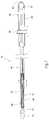
- FIG. 1Ais a perspective view of a prosthesis delivery catheter embodies features of the invention.
- FIG. 1Bis an enlarged perspective view, with portions broken away and in section, of the distal end of the prosthesis delivery catheter shown in FIG. 1A .
- FIG. 2is a perspective view of the prosthesis delivery catheter shown in FIG. 1A , being positioned within an abdominal aortic aneurysm.
- FIG. 3is a perspective view of a straight endovascular prosthesis after deployment by the prosthesis delivery catheter shown in FIG. 1A .
- FIG. 4is a perspective view of a bifurcated endovascular prosthesis after deployment by the prosthesis delivery catheter shown in FIG. 1A .
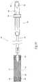
- FIG. 5Ais an enlarged perspective view, with portions broken away and in section, of the inner assembly which is located in the distal end of the prosthesis delivery catheter shown in FIG. 1A .
- FIG. 5Bis an enlarged perspective view, with portions broken away and in section, of the inner assembly which is located in the distal end of the prosthesis delivery catheter shown in FIG. 5A , showing a prosthesis retained in a collapsed condition by restraining means prior to deployment.
- FIG. 5Cis an enlarged perspective view, with portions broken away and in section, of the inner assembly which is located in the distal end of the prosthesis delivery catheter shown in FIG. 5A , showing the prosthesis in an expanded condition after removal of the restraining means.
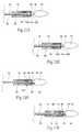
- FIG. 6is a side view, with portions broken away and in section, of the prosthesis delivery catheter shown in FIG. 1A , showing the catheter retaining a prosthesis in a collapsed condition prior to deployment, the outer sheath being shown in an advanced position over the prosthesis.
- FIG. 7is a side view, with portions broken away and in section, of the prosthesis delivery catheter shown in FIG. 6 , showing the catheter retaining a prosthesis in a collapsed condition prior to deployment, the outer sheath being shown in a position withdrawn from the prosthesis.
- FIG. 8is a side view, with portions broken away and in section, of the prosthesis delivery catheter shown in FIG. 7 , showing the catheter retaining a prosthesis in a collapsed condition prior to deployment, with the pull wire still advanced to restrain radial expansion of the prosthesis.
- FIG. 9is a side view, with portions broken away and in section, of the prosthesis delivery catheter shown in FIG. 8 , showing the prosthesis in a radially expanded condition after actuation of the pull wire to remove the restraining means.
- FIG. 10is a side view, with portions broken away and in section, of the prosthesis delivery catheter shown in FIG. 9 , showing the withdrawal of the catheter from the prosthesis after its deployment.
- FIG. 11Ais a simplified side view of the distal end of the prosthesis delivery catheter shown in FIG. 5B , with the outer sheath removed, showing the releasing means retaining the prosthesis in a restrained condition.
- FIG. 11Bis an end section view of the distal end of the prosthesis delivery catheter shown in FIG. 11A , taken generally along line 11 B- 11 B in FIG. 11A .
- FIG. 11Cis a simplified side view of the distal end of the prosthesis delivery catheter shown in FIG. 5B , with the outer sheath removed, showing an alternative embodiment of a restraining means for maintaining the releasing means in a desired orientation while retaining the prosthesis in a restrained condition.
- FIGS. 12A and 12Bare simplified side views of the distal end of the prosthesis delivery catheter shown in FIG. 5B , with the outer sheath removed, showing other alternative embodiments of a restraining means for maintaining the releasing means in a desired orientation while retaining the prosthesis in a restrained condition, without reliance upon the catheter tip component.
- FIGS. 13A and 13Bare simplified side views of the distal end of the prosthesis delivery catheter shown in FIG. 5B , with the outer sheath removed, showing other alternative embodiments of a restraining means for maintaining the releasing means in a desired orientation while retaining the prosthesis in a restrained condition, without reliance upon a tubular sleeve carried by the central shaft.
- FIGS. 14A and 14Bare simplified side views of the distal end of the prosthesis delivery catheter shown in FIG. 5B , with the outer sheath removed, showing other alternative embodiments of a releasing means with a cutting element for selectively releasing the prosthesis for use, together with an associated restraining means for maintaining the releasing means in a desired orientation for operation.
- FIGS. 15A and 15Bare simplified side views of the distal end of the prosthesis delivery catheter shown in FIG. 5B , with the outer sheath removed, showing other alternative embodiments of a releasing means with a wedge element for selectively releasing the prosthesis for use, together with an associated restraining means for maintaining the releasing means in a desired orientation for operation.
- FIGS. 1A and 1Bshow a prosthesis delivery catheter 10 .
- the purpose of the catheter 10is to (i) contain and/or restrain a prosthesis 14 prior to its deployment (see FIG. 1B ), (ii) deliver the prosthesis 14 through the vasculature to a desired location within the body, e.g., a hollow body organ or a blood vessel (see FIG. 2 ), and (iii) controllably deploy the prosthesis 14 in the desired location (see FIG. 3 ).
- the prosthesis 14takes the form of an endovascular, self-expanding stent prosthesis.
- the prosthesis or prostheses 14may have a wide variety of conventional configurations. It can typically comprise a fabric or some other blood semi-impermeable flexible barrier which is supported by a structure formed by stents 48 .
- the stent structurecan have any conventional stent configuration, such as zigzag, serpentine, expanding diamond, or combinations thereof.
- the stent structuremay extend the entire length of the prosthesis, and in some instances can be longer than the fabric components of the prosthesis. Alternatively, the stent structure can cover only a small portion of the prosthesis, e.g., being present at the ends.
- the stent structuremay have three or more ends when it is configured to treat bifurcated vascular regions, such as the treatment of abdominal aortic aneurysms, when the stent prosthesis extends into the iliac arteries.
- the stent structurescan be spaced apart along the entire length, or at least a major portion of the entire length, of the stent-prosthesis, where individual stent structures are not connected to each other directly, but rather connected to the fabric or other flexible component of the prosthesis.
- the stent structurescould be attached to one another at discrete locations, e.g., in the proximal neck region.
- Such stent structurescould comprise individual stents that are connected together when incorporated into the prosthesis, or stents that are manufactured in a joined condition prior to incorporation into the prosthesis.
- the stents 48may be elastic, e.g., comprised of a shape memory alloy elastic stainless steel, or the like.
- expandingtypically comprises releasing the stent structure from a constraint to permit the stent structure to self-expand at the implantation site.
- the catheter 10places a sheath over the stent structure, in combination with releasable restraining means coupled to the stent structure, to maintain the stent structure in a radially reduced configuration during passage into the body.
- self-expansion of the stent structureis achieved by pulling back on the sheath and release of the restraining means, to permit the stent structure to assume its larger diameter configuration.
- the stent structuremay be formed from a malleable material, such as malleable stainless steel of other metals. Expansion may then comprise applying a radially expansive force within the structure to cause expansion, e.g., inflating a delivery catheter within the stent structure in order to affect the expansion.
- the positioning and deployment of the endoprosthesiscan be accomplished by the use of an expansion means either separate or incorporated into the deployment catheter. This will allow the endoprosthesis to be positioned within the vessel and partially deployed while checking relative position within the vessel.
- the expansioncan be accomplished either via a balloon or mechanical expansion device.
- the stent structuremay comprise a combination of a self-expanding stent and a malleable stent structure.
- the catheter 10is shown it is being positioned over a guidewire 12 in a body lumen.
- the catheter 10carries the prosthesis 14 in a radially reduced configuration to a targeted site.
- the catheter 10releases the radially reduced prosthesis 14 , which expands radially (see FIG. 3 ).
- one or more fastenersare desirably introduced by a fastener attachment assembly to anchor the prosthesis 14 in place. Further details of the fastener attachment assembly can be found in U.S.
- the prosthesis 14can be sized and configured to be either straight or bifurcated form.
- FIG. 3depicts a completely deployed straight prosthesis 14 .
- FIG. 4depicts a completely deployed bifurcated prosthesis.
- FIG. 2shows the targeted site as being within an abdominal aortic aneurysm.
- the targeted sitecan be elsewhere in the body.
- the catheter 10comprises an inner assembly 16 , an outer sheath 18 , and a handle assembly 20 . These components will now be individually described in greater detail.
- the inner assembly 16comprises a central shaft 22 , which functions as a carrier for the prosthesis.
- the inner assemblyalso includes a catheter tip component 24 , a releasing means or mechanism 28 for retaining at least a portion of the prosthesis 14 in a radially compressed condition prior to deployment, a retaining means or mechanism 26 for maintaining the releasing means 28 in a desired relationship with the central shaft 22 during use, and a spacer 30 .
- the central shaft 22 , the retaining means 26 , the releasing means 28 , and the spacer 30are located within the confines of the outer sheath 18 .
- the outer sheath 18functions as an enclosure for the prosthesis on the carrier.
- the catheter tip component 24is attached the distal end of the central shaft 22 , and the distal end of the outer sheath 18 terminates adjacent the catheter tip component 24 .
- the catheter tip component 24extends outward beyond the outer sheath 18 .
- the central shaft 22 , the releasing means 28 , and the outer sheath 18connect to the handle assembly 20 at the proximal end of the catheter 10 (see FIG. 1A ).
- the prosthesis 14is contained in a cavity 32 defined between the central shaft 22 and the outer sheath 18 in the distal section of the catheter 10 (this arrangement is also shown in FIG. 1B ).
- the central shaft 22extends from the handle assembly 20 (see FIG. 1A ) to the catheter tip component 24 .
- the central shaft 22may be made, e.g., from stainless steel or other suitable medical materials including other metals or polymers.
- the central shaft 22desirably has at least one lumen 36 (see FIG. 5A ), with an inner diameter between 0.010 and 0.120 inches, preferably between 0.03 and 0.06 inches and most preferably between 0.04 and 0.05 inches.
- the central lumen 36allows for the insertion of a guide wire 12 up to 0.038′′ diameter.
- the catheter tip component 24also desirably has at least one lumen 38 (see FIG. 5A ) configured to align with at least one lumen within the central shaft 22 .
- This lumen 38allows for the insertion of a guide wire 12 through the central shaft 22 and through the catheter tip component 24 (see FIG. 2 ).
- this lumenwill have an inner diameter between 010 and 0.120 inches, preferably between 0.03 and 0.06 inches and most preferably between 0.04 and 0.05 inches.
- the catheter tip component 24is flexible and has a long, tapered distal end and a shorter, tapered proximal end.
- the maximum diameter of the catheter tip component 24is approximately the same as the outside diameter of the distal end of the outer sheath 18 .
- the distal end of the catheter tip component 24provides a smooth tapered transition from the lumen 38 containing the guide wire 12 to the distal edge of the outer sheath 18 . This feature aids in catheter insertion and navigation through tortuous anatomy over the guide wire 12 .
- the tapered section on the proximal end of the catheter tip component 24prevents the catheter tip component 24 from inadvertently engaging the prosthesis 14 , portions of the surrounding anatomy, or an introducer sheath or the like during removal of the catheter 10 from the body.
- the retaining means 26holds the releasing means 28 in a desired, close relationship with the central shaft 22 .
- the retaining means 26orients the releasing means 28 along the axis to of the central shaft 22 and allows the releasing means 28 longitudinal movement in this axis.
- the retaining means 26includes a small hole or recess 40 in the proximal end of the catheter tip component 24 and a tube 56 having a diameter sufficiently large to accommodate both the central shaft 22 and the releasing means 28 .
- FIGS. 5Athe retaining means 26 includes a small hole or recess 40 in the proximal end of the catheter tip component 24 and a tube 56 having a diameter sufficiently large to accommodate both the central shaft 22 and the releasing means 28 .
- the tube 56 of the retaining means 26is located over the central shaft 22 in alignment with and adjacent to the recess 40 on the catheter tip component 24 .
- the tube 56is attached to the central shaft 22 in a manner in that retains a crescent shape lumen 42 between the tube 56 and the central shaft 22 .
- the releasing means 28extends through this lumen 42 and into the recess 40 .
- the spacer 30provides support for the outer sheath 18 and, by occupying space within the outer sheath 18 , reduces the amount of air entrapped within the catheter 10 .
- the distal end of the spacer 30desirably terminates adjacent the proximal end of the prosthesis 14 (as FIG. 5B shows).
- the cavity 32 containing the prosthesis 14extends from the proximal end of the catheter tip component 24 to the distal end of the spacer 30 .
- the spacer 30is positioned over the central shaft 22 and releasing means 28 and the proximal end of the spacer 30 is connected to the handle assembly 20 .
- the spacer 30can have an outer diameter slightly less than the inner diameter of the outer sheath 18 .
- the spacer 30can comprise a single lumen or an array of multiple lumens for passage of the various components within the spacer 30 .
- the releasing means 28holds the prosthesis 14 in a desired configuration prior to deployment (see FIG. 5B ) and selectively releases the prosthesis 14 for deployment (see FIG. 5C ).
- the proximal end of the releasing means 28is connected to an actuator or control button or knob 46 in the handle assembly 20 (see FIG. 1A ).
- the releasing means 28extends along the outside of the central shaft 22 , through the inside of the spacer 30 , and continues distally through the inside of the prosthesis 14 .
- the releasing means 28passes through the prosthesis 14 and the retaining means 26 .
- the prosthesis 14is retained by the releasing means 28 along the central shaft 22 in the cavity 32 , which extends between the proximal end of the catheter tip component 24 and the distal end of the spacer 30 .
- the releasing means 28includes a wire 58 that extends along the central shaft 22 .
- the distal end of the wire 58passes through the crescent shape lumen 42 of the retaining means 26 , and is ultimately captured in the hole or recess 40 of the retaining means 26 in the proximal end of the catheter tip component 24 .
- the distal end of the wire 58is thereby kept in a desired relationship along the central shaft 22 .
- the proximal end of the wire 58is coupled to the control button 46 , such that fore and aft movement of the button 46 advances the wire 58 , respectively, distally and proximally.
- the retaining means 28includes sutures 44 and/or equivalent structures, which are attached to one or more stents 48 on the prosthesis 14 .
- the sutures 44are, in turn, looped around the wire 58 of the releasing means 28 , when the wire 58 is in its distal-most position, as FIG. 5B shows.
- Proximal advancement of the wire 58withdraws the wire 58 from the suture loops 44 , as FIG. 5C shows.
- the suture loops 44are attached to one or more stents 48 at the distal end of the prosthesis 14 . It should be appreciated, however, that suture loops 44 could be attached to stents 44 elsewhere in the prosthesis 14 , and/or the other components of the prosthesis 14 as well.
- the suture loops 44 and wire 56 of the embodiment of the releasing means 28 just describedretain the prosthesis 14 to the central shaft (see FIG. 5B ).
- the suture loops 44 and the wire 56keep the prosthesis 14 from moving proximally as the outer sheath 18 is retracted.
- the releasing means 28also keeps the stents 48 that are coupled to the suture loops 44 in a radially compressed condition as the outer sheath 18 is removed.
- the suture loops 44 and wire 56prevent the distal end of the prosthesis 14 from self-expanding until the releasing means 28 has been withdrawn.
- the withdrawal of the releasing means 28is accomplished by operating the control button 46 to move the wire 58 proximally, withdrawing the wire 58 from the hole or recess 40 and away from the suture loops 44 .
- the control button 46moves the wire 58 proximally, withdrawing the wire 58 from the hole or recess 40 and away from the suture loops 44 .
- the releasing means 28is coupled to one restrained component of the prosthesis 14 . It should be appreciated, however, that the releasing means 28 can be coupled to the prosthesis 14 at two or more restrained regions, so that withdrawal of the releasing means 28 frees the prosthesis at two or more restrained regions. It should also be appreciated that the releasing means 28 can comprise more than a single releasing element. For example, multiple, individual releasing wires 58 could be coupled to the prosthesis 14 at different regions, so that release of separate regions of the prosthesis 14 can be individually controlled.
- the outer sheath 18also serves to restrain the stents 48 on the prosthesis 14 from expanding and allows for a control deployment of the prosthesis 14 within the body.
- the outer sheath 18is connected to an actuator or a collar or knob 50 on the handle assembly 20 .
- the outer sheath 18extends distally over the spacer 30 and prosthesis 14 and terminates adjacent the proximal and of the catheter tip component 24 .
- the outer sheath 18can be made of a polymer tube and be free of structural reinforcement.
- the outer sheath 18is tapered due to the difference in outer diameters of the catheter tip component and the spacer 30 .
- the larger diameter of the outer sheath 18is intended to contain the main body of the prosthesis 14 and the smaller diameter would contain the leg portion or portions of the prosthesis 14 , if present (as in the embodiment shown in FIG. 4 ).
- the smaller diametercontinues proximally to the handle assembly 20 .
- This tapered feature of the outer sheath 18also allows for better blood circulation passed the catheter.
- the handle assembly 20provides the operator with longitudinal and rotational control of the catheter 10 within the body and provides access to the actuator or control means for deploying the prosthesis 14 .
- the handle assembly 20comprises a handle body 52 and the sliding knob or collar 50 which is connected to the proximal and the of the outer sheath 18 , and the knob or button 46 which is attached to proximal end of the releasing means 28 .
- the central shaft 22is captured within the handle and has a guide wire receiving luer 34 connected to its proximal end, which is located at the proximal end of the handle assembly 20 . This design prevents the position of the prosthesis 14 from moving relative to the handle body 52 while the outer sheath 18 is retracted.
- the sliding knob 50is moved proximally until the distal end of the outer sheath 18 is free of the prosthesis 14 (see FIG. 8 ).
- the portion or portions of the prosthesis 14 that are not coupled to the releasing means 28(which, in the illustrated embodiment comprise the proximal region of the prosthesis 14 ) are free to self-expand, as FIG. 8 shows.
- the portions of the prosthesis 14 that are coupled to the releasing means 58(which, in the illustrated embodiment comprise the distal region of the prosthesis 14 ) are still restrained from self-expansion, despite withdrawal of the outer sheath 18 , as FIG. 8 also shows.
- the stent structure of the prosthesis 14is thereby kept restrained closely against the central shaft tube 22 while the outer sheath 18 is retracted.
- the retaining means 26prevents the prosthesis 14 from moving relative to the central tube 22 during retraction of the outer sheath 18 , which potentially minimizes blood flow through the prosthesis 14 during the deployment process.
- the prosthesis 14is not “pushed out” of the catheter.
- the prosthesis 14therefore need not have longitudinal stiffness or a stent structure with a “spine”.
- the sliding button 46is moved proximally until the distal end of the releasing means 28 is withdrawn from the restraining means 26 .
- the prosthesisis thereby free to fully self-expand, as FIG. 9 and FIG. 5C show.
- the prosthesis 14is not released immediately from distal end to proximal end as the sheath 18 is withdrawn.
- the prosthesis 14is pulled in tension, which “stretches” the prosthesis to its proper length and stent spacing.
- the distal stent or stents 48are released in a secondary operation, which follows the withdrawal of the outer sheath 18 (as shown in FIGS. 5C , 8 , and 9 ).
- Final placement of distal end of the prosthesis 14can therefore comprise a final step in the deployment process.
- knob 50can comprise a separate component that is not part of the handle assembly 20 , i.e., on the outer sheath 18 .
- the catheter 10is navigated over the guide wire 12 to the desired location within the body (as FIG. 2 shows).
- deployment of the prosthesis 14is achieved in a two step process.
- the outer sheath 18is retracted and exposes the prosthesis 14 (as FIGS. 6 and 7 show).
- the unrestrained portion or portions of the prosthesis 14self-expand, as FIG. 8 show.
- FIGS. 6 and 7show, during retraction of the outer sheath 18 , the prosthesis 14 maintains its position relative to the central shaft 22 due to the releasing means 28 connected to the prosthesis 44 .
- the control button or knob 46 on the handle assembly 20is moved proximally (see FIGS. 8 and 9 ). This causes the distal end of the releasing means 28 to be withdrawn and allows the restrained stent or stents 44 , and the prosthesis 14 as a whole, to self-expand radially (as FIGS. 5C and 9 show).
- the prosthesis 14enlarges to contact the internal walls of the vessel or hollow body organ, as FIG. 3 shows.
- the catheter 10can then be withdrawn (as FIG. 10 shows).
- the withdrawal of the outer sheath 18 and the withdrawal of the releasing means 28can be accomplished in a single step process.
- a single activation mechanismcan be jointly coupled to the outer sheath 18 and the releasing means 28 , so that the outer sheath 18 and releasing means 28 are withdrawn in a single step.
- the distal end of a movable component of the releasing means 28extends along the central shaft 22 in a manner prescribed and controlled by the restraining means 26 , i.e., between a tube 56 carried by the central shaft 22 and a recess 40 located in the proximal end of the catheter tip component 24 . It is in the region between the tube 56 and the recess 40 , that a stationary component of the releasing means 28 , which is attached to the prosthesis 14 (e.g., the suture loops 44 ), is operatively coupled to the movable component of the releasing means 28 .
- the restraining means 26serves to maintain the movable component 58 of the releasing means 28 in a desired operative alignment with the central shaft 22 , as well as in a desired operative relationship with the stationary component 44 of the releasing means 28 , such that quick and certain release of the prosthesis 14 occurs.
- the releasing means 28 and the restraining means 26can be variously constructed to meet this objective.
- the distal end of the movable component 58 of the releasing means 28extends along the central shaft 22 in a manner prescribed and controlled by the restraining means 26 , i.e., between adjacent, spaced apart tubes 60 A, and 60 B, without dependence upon additional support by the catheter tip component 24 .
- Each tube 60 A and 60 Bsurrounds the central shaft 22 in the same fashion as the single tube 56 shown in FIGS. 11A to 11C .
- the movable component 58 of the releasing means 28is held in the region between the two tubes 60 A and 60 B in operative association with the stationary component 44 of the releasing means 28 , and can be quickly and certainly withdrawn from this region to release the prosthesis 14 .
- the distal end of the movable component 58 of the releasing means 28extends along the central shaft 22 between adjacent, spaced apart external tubes 62 A and 62 B, again without dependence upon additional support by the catheter tip component 24 .
- the tubes 62 A and 62 Bproject along the exterior of the central shaft 22 , but do not surround it.
- a single external support tube like tube 62 A or 62 Bcould, alternatively, be used in a hybrid combination with the recess 40 in the catheter tip component 24 , if desired.
- the distal end of the movable component 58 of the releasing means 28extends within a lumen in the 66 central shaft 22 , exiting through an aperture 64 in the shaft 22 and into a recess 40 in the catheter tip component 24 .
- the movable component 58 of the releasing means 28is held in the region between the aperture 64 and the recess 40 in operative association with the stationary component 44 of the releasing means 28 , and can be quickly and certainly withdrawn from this region to release the prosthesis 14 .
- FIG. 13Athe distal end of the movable component 58 of the releasing means 28 extends within a lumen in the 66 central shaft 22 , exiting through an aperture 64 in the shaft 22 and into a recess 40 in the catheter tip component 24 .
- the movable component 58 of the releasing means 28is held in the region between the aperture 64 and the recess 40 in operative association with the stationary component 44 of the releasing means 28 , and can be quickly and certainly withdrawn from this region to release the pros
- the distal end of the movable component 58 of the releasing means 28extends within a lumen 68 the central shaft 22 between adjacent, spaced apart apertures 70 and 72 .
- the movable component 58exits the aperture 72 and enters a recess 40 in the catheter tip component 24 .
- the movable component 58 of the releasing means 28is held in the region between the aperture 72 and the recess 40 in operative association with the stationary component 44 of the releasing means 28 , and can be quickly and certainly withdrawn from this region to release the prosthesis 14 .
- the restraining means 26includes a single tube 74 carried by the central shaft 22 , through which the movable component 58 of the releasing means 28 passes.
- the tube 74can comprise a surrounding tube of the type shown in FIG. 12A (as FIGS. 14A and 14B show) or an external tube of the type shown in FIG. 12B .
- the releasing means 28includes a suture loop 76 carried by the proximal end of the catheter tip component 24 and a cutting element 78 carried on the distal end of the movable component 58 of the releasing means 28 .
- the suture loop 76passes through the suture loops 44 on the prosthesis 14 , as well as through the cutting element 78 .
- the cutting element 78 on the distal end of the movable component 58 of the releasing means 28extends along the central shaft 22 in a manner prescribed and controlled by the restraining means 26 , i.e., through and beyond the tube 74 , and in operative association with the suture loops 44 and 76 , which, in this embodiment, comprise the stationary components of the releasing means 28 .
- the restraining means 26includes a single tube 80 carried by the central shaft 22 , through which the movable component 58 of the releasing means 28 passes.
- the tube 80can comprise a surrounding tube of the type shown in FIG. 12A (as FIGS. 15A and 15B show) or an external tube of the type shown in FIG. 12B .
- the releasing means 28includes a wedge element 84 carried on the distal end of the movable component 58 of the releasing means 28 .
- the wedge element 84nests within a mating wedge surface 86 formed in the proximal end of the catheter tip component 24 . Advancement of the movable component 58 moves the wedge element 84 into the registration within the wedge surface 86 (as FIG. 15A shows) and out of registration with the wedge surface 86 (as FIG. 15B shows).
- the releasing means 28 in this arrangementfurther includes alternative embodiments of suture loops 82 or 82 ′, which are pinched between the wedge element 84 and the wedge surface 86 when the element 84 and the surface 86 are in registration, as FIG. 15A shows.
- the embodiment of the suture loop 82comprises a closed loop 82 carried by a prosthesis stent 48 .
- the embodiment of the suture loop 82 ′comprises an open loop 82 ′ carried by the proximal end of the catheter tip component 24 and looped through a prosthesis stent 48 .
- expansion of the prosthesis 14is restrained (as FIG. 15A shows).
Landscapes
- Health & Medical Sciences (AREA)
- Engineering & Computer Science (AREA)
- Biomedical Technology (AREA)
- Life Sciences & Earth Sciences (AREA)
- General Health & Medical Sciences (AREA)
- Transplantation (AREA)
- Heart & Thoracic Surgery (AREA)
- Vascular Medicine (AREA)
- Cardiology (AREA)
- Animal Behavior & Ethology (AREA)
- Oral & Maxillofacial Surgery (AREA)
- Public Health (AREA)
- Veterinary Medicine (AREA)
- Gastroenterology & Hepatology (AREA)
- Pulmonology (AREA)
- Prostheses (AREA)
- Media Introduction/Drainage Providing Device (AREA)
- Medicines That Contain Protein Lipid Enzymes And Other Medicines (AREA)
- Infusion, Injection, And Reservoir Apparatuses (AREA)
Abstract
Description
Claims (2)
Priority Applications (7)
| Application Number | Priority Date | Filing Date | Title |
|---|---|---|---|
| US11/633,724US8080050B2 (en) | 2003-07-21 | 2006-12-05 | Prosthesis delivery systems and methods |
| US12/288,031US20090099650A1 (en) | 2001-11-28 | 2008-10-16 | Devices, systems, and methods for endovascular staple and/or prosthesis delivery and implantation |
| US12/288,045US20090138072A1 (en) | 2001-11-28 | 2008-10-16 | Devices, systems, and methods for endovascular staple and/or prosthesis delivery and implantation |
| US12/288,034US20090112303A1 (en) | 2001-11-28 | 2008-10-16 | Devices, systems, and methods for endovascular staple and/or prosthesis delivery and implantation |
| US12/288,032US20090112302A1 (en) | 2001-11-28 | 2008-10-16 | Devices, systems, and methods for endovascular staple and/or prosthesis delivery and implantation |
| US13/291,942US20120059450A1 (en) | 2003-07-21 | 2011-11-08 | Prosthesis delivery systems and methods |
| US15/246,271US10194905B2 (en) | 2001-11-28 | 2016-08-24 | Devices, systems, and methods for endovascular staple and/or prosthesis delivery and implantation |
Applications Claiming Priority (3)
| Application Number | Priority Date | Filing Date | Title |
|---|---|---|---|
| US48875303P | 2003-07-21 | 2003-07-21 | |
| US10/692,283US7147657B2 (en) | 2003-10-23 | 2003-10-23 | Prosthesis delivery systems and methods |
| US11/633,724US8080050B2 (en) | 2003-07-21 | 2006-12-05 | Prosthesis delivery systems and methods |
Related Parent Applications (2)
| Application Number | Title | Priority Date | Filing Date |
|---|---|---|---|
| US10/692,283DivisionUS7147657B2 (en) | 2001-11-28 | 2003-10-23 | Prosthesis delivery systems and methods |
| US10/692,283ContinuationUS7147657B2 (en) | 2001-11-28 | 2003-10-23 | Prosthesis delivery systems and methods |
Related Child Applications (2)
| Application Number | Title | Priority Date | Filing Date |
|---|---|---|---|
| US11/254,619Continuation-In-PartUS9320503B2 (en) | 2001-11-28 | 2005-10-20 | Devices, system, and methods for guiding an operative tool into an interior body region |
| US13/291,942ContinuationUS20120059450A1 (en) | 2003-07-21 | 2011-11-08 | Prosthesis delivery systems and methods |
Publications (2)
| Publication Number | Publication Date |
|---|---|
| US20070083255A1 US20070083255A1 (en) | 2007-04-12 |
| US8080050B2true US8080050B2 (en) | 2011-12-20 |
Family
ID=34522082
Family Applications (3)
| Application Number | Title | Priority Date | Filing Date |
|---|---|---|---|
| US10/692,283Expired - LifetimeUS7147657B2 (en) | 2001-11-28 | 2003-10-23 | Prosthesis delivery systems and methods |
| US11/633,724Expired - LifetimeUS8080050B2 (en) | 2001-11-28 | 2006-12-05 | Prosthesis delivery systems and methods |
| US13/291,942AbandonedUS20120059450A1 (en) | 2003-07-21 | 2011-11-08 | Prosthesis delivery systems and methods |
Family Applications Before (1)
| Application Number | Title | Priority Date | Filing Date |
|---|---|---|---|
| US10/692,283Expired - LifetimeUS7147657B2 (en) | 2001-11-28 | 2003-10-23 | Prosthesis delivery systems and methods |
Family Applications After (1)
| Application Number | Title | Priority Date | Filing Date |
|---|---|---|---|
| US13/291,942AbandonedUS20120059450A1 (en) | 2003-07-21 | 2011-11-08 | Prosthesis delivery systems and methods |
Country Status (11)
| Country | Link |
|---|---|
| US (3) | US7147657B2 (en) |
| EP (1) | EP1682039B1 (en) |
| JP (2) | JP4912883B2 (en) |
| CN (1) | CN1870950B (en) |
| AT (1) | ATE438362T1 (en) |
| AU (1) | AU2004287353A1 (en) |
| CA (1) | CA2539265A1 (en) |
| DE (1) | DE602004022446D1 (en) |
| DK (1) | DK1682039T3 (en) |
| ES (1) | ES2356352T3 (en) |
| WO (1) | WO2005044073A2 (en) |
Cited By (11)
| Publication number | Priority date | Publication date | Assignee | Title |
|---|---|---|---|---|
| US8685044B2 (en) | 2001-11-28 | 2014-04-01 | Aptus Endosystems, Inc. | Systems and methods for attaching a prosthesis with a body lumen or hollow organ |
| US9023065B2 (en) | 2001-11-28 | 2015-05-05 | Aptus Endosystems, Inc. | Devices, systems, and methods for supporting tissue and/or structures within a hollow body organ |
| US9320591B2 (en) | 2001-11-28 | 2016-04-26 | Medtronic Vascular, Inc. | Devices, systems, and methods for prosthesis delivery and implantation, including the use of a fastener tool |
| US9320589B2 (en) | 2001-11-28 | 2016-04-26 | Medtronic Vascular, Inc. | Endovascular aneurysm repair system |
| US9572652B2 (en) | 2009-12-01 | 2017-02-21 | Altura Medical, Inc. | Modular endograft devices and associated systems and methods |
| US9737426B2 (en) | 2013-03-15 | 2017-08-22 | Altura Medical, Inc. | Endograft device delivery systems and associated methods |
| US9968353B2 (en) | 2001-06-04 | 2018-05-15 | Medtronic Vascular, Inc. | Catheter based fastener implantation apparatus and methods |
| US10098770B2 (en) | 2001-11-28 | 2018-10-16 | Medtronic Vascular, Inc. | Endovascular aneurysm devices, systems, and methods |
| US10194905B2 (en) | 2001-11-28 | 2019-02-05 | Medtronic Vascular, Inc. | Devices, systems, and methods for endovascular staple and/or prosthesis delivery and implantation |
| US10285833B2 (en) | 2012-08-10 | 2019-05-14 | Lombard Medical Limited | Stent delivery systems and associated methods |
| US11020255B2 (en) | 2010-06-24 | 2021-06-01 | CARDINAL HEALTH SWITZERLAND 515 GmbH | Apparatus for and method of pulling a tensile member from a medical device |
Families Citing this family (190)
| Publication number | Priority date | Publication date | Assignee | Title |
|---|---|---|---|---|
| ATE415895T1 (en) | 2001-07-06 | 2008-12-15 | Angiomed Ag | DELIVERY SYSTEM HAVING A SELF-EXPANDING STENT SLIDE ASSEMBLY AND A QUICK-CHANGE CONFIGURATION |
| GB0123633D0 (en) | 2001-10-02 | 2001-11-21 | Angiomed Ag | Stent delivery system |
| US20110087320A1 (en)* | 2001-11-28 | 2011-04-14 | Aptus Endosystems, Inc. | Devices, Systems, and Methods for Prosthesis Delivery and Implantation, Including a Prosthesis Assembly |
| US20090112303A1 (en)* | 2001-11-28 | 2009-04-30 | Lee Bolduc | Devices, systems, and methods for endovascular staple and/or prosthesis delivery and implantation |
| US9320503B2 (en) | 2001-11-28 | 2016-04-26 | Medtronic Vascular, Inc. | Devices, system, and methods for guiding an operative tool into an interior body region |
| US7147657B2 (en) | 2003-10-23 | 2006-12-12 | Aptus Endosystems, Inc. | Prosthesis delivery systems and methods |
| ES2279156T3 (en) | 2002-06-11 | 2007-08-16 | Tyco Healthcare Group Lp | MALE TIGHTS FOR HERNIAS. |
| EP1589903B1 (en) | 2003-01-15 | 2016-01-13 | Angiomed GmbH & Co. Medizintechnik KG | Trans-luminal surgical device |
| GB0327306D0 (en)* | 2003-11-24 | 2003-12-24 | Angiomed Gmbh & Co | Catheter device |
| US8926637B2 (en) | 2003-06-13 | 2015-01-06 | Covidien Lp | Multiple member interconnect for surgical instrument and absorbable screw fastener |
| US7670362B2 (en) | 2003-06-13 | 2010-03-02 | Tyco Healthcare Group Lp | Multiple member interconnect for surgical instrument and absorbable screw fastener |
| US9198786B2 (en) | 2003-09-03 | 2015-12-01 | Bolton Medical, Inc. | Lumen repair device with capture structure |
| US8500792B2 (en) | 2003-09-03 | 2013-08-06 | Bolton Medical, Inc. | Dual capture device for stent graft delivery system and method for capturing a stent graft |
| US20070198078A1 (en) | 2003-09-03 | 2007-08-23 | Bolton Medical, Inc. | Delivery system and method for self-centering a Proximal end of a stent graft |
| US11259945B2 (en) | 2003-09-03 | 2022-03-01 | Bolton Medical, Inc. | Dual capture device for stent graft delivery system and method for capturing a stent graft |
| US20080264102A1 (en) | 2004-02-23 | 2008-10-30 | Bolton Medical, Inc. | Sheath Capture Device for Stent Graft Delivery System and Method for Operating Same |
| US11596537B2 (en) | 2003-09-03 | 2023-03-07 | Bolton Medical, Inc. | Delivery system and method for self-centering a proximal end of a stent graft |
| US7763063B2 (en) | 2003-09-03 | 2010-07-27 | Bolton Medical, Inc. | Self-aligning stent graft delivery system, kit, and method |
| US8292943B2 (en) | 2003-09-03 | 2012-10-23 | Bolton Medical, Inc. | Stent graft with longitudinal support member |
| US10478179B2 (en) | 2004-04-27 | 2019-11-19 | Covidien Lp | Absorbable fastener for hernia mesh fixation |
| AU2005262541B2 (en)* | 2004-06-16 | 2011-04-21 | Cook Incorporated | Thoracic deployment device and stent graft |
| US7462185B1 (en)* | 2004-12-23 | 2008-12-09 | Cardican Inc. | Intravascular stapling tool |
| US7678121B1 (en) | 2004-12-23 | 2010-03-16 | Cardica, Inc. | Surgical stapling tool |
| US8608797B2 (en) | 2005-03-17 | 2013-12-17 | Valtech Cardio Ltd. | Mitral valve treatment techniques |
| US7344544B2 (en) | 2005-03-28 | 2008-03-18 | Cardica, Inc. | Vascular closure system |
| US8333777B2 (en) | 2005-04-22 | 2012-12-18 | Benvenue Medical, Inc. | Catheter-based tissue remodeling devices and methods |
| US8951285B2 (en) | 2005-07-05 | 2015-02-10 | Mitralign, Inc. | Tissue anchor, anchoring system and methods of using the same |
| US8123795B1 (en) | 2005-10-03 | 2012-02-28 | Cardica, Inc. | System for attaching an abdominal aortic stent or the like |
| WO2007134290A2 (en)* | 2006-05-12 | 2007-11-22 | Ev3, Inc. | Implant and delivery system with multiple marker interlocks |
| US9585743B2 (en) | 2006-07-31 | 2017-03-07 | Edwards Lifesciences Cardiaq Llc | Surgical implant devices and methods for their manufacture and use |
| EP3360509B1 (en) | 2006-07-31 | 2022-06-22 | Syntheon TAVR, LLC | Sealable endovascular implants |
| US7875053B2 (en)* | 2006-09-15 | 2011-01-25 | Cardica, Inc. | Apparatus and method for closure of patent foramen ovale |
| WO2008066923A1 (en)* | 2006-11-30 | 2008-06-05 | William Cook Europe Aps | Implant release mechanism |
| US11259924B2 (en) | 2006-12-05 | 2022-03-01 | Valtech Cardio Ltd. | Implantation of repair devices in the heart |
| US9883943B2 (en) | 2006-12-05 | 2018-02-06 | Valtech Cardio, Ltd. | Implantation of repair devices in the heart |
| US11660190B2 (en) | 2007-03-13 | 2023-05-30 | Edwards Lifesciences Corporation | Tissue anchors, systems and methods, and devices |
| US9149379B2 (en)* | 2007-07-16 | 2015-10-06 | Cook Medical Technologies Llc | Delivery device |
| US9566178B2 (en)* | 2010-06-24 | 2017-02-14 | Edwards Lifesciences Cardiaq Llc | Actively controllable stent, stent graft, heart valve and method of controlling same |
| WO2009023221A1 (en)* | 2007-08-13 | 2009-02-19 | William A. Cook Australia Pty. Ltd. | Deployment device |
| DE112008002454T5 (en)* | 2007-09-11 | 2010-07-22 | Laboratoires Perouse | Device for treating a blood circulation device |
| US20090093826A1 (en)* | 2007-10-05 | 2009-04-09 | Cardica, Inc. | Patent Foramen Ovale Closure System |
| GB2476451A (en) | 2009-11-19 | 2011-06-29 | Cook William Europ | Stent Graft |
| US9180030B2 (en) | 2007-12-26 | 2015-11-10 | Cook Medical Technologies Llc | Low profile non-symmetrical stent |
| US8574284B2 (en) | 2007-12-26 | 2013-11-05 | Cook Medical Technologies Llc | Low profile non-symmetrical bare alignment stents with graft |
| GB2475494B (en)* | 2009-11-18 | 2011-11-23 | Cook William Europ | Stent graft and introducer assembly |
| US9226813B2 (en) | 2007-12-26 | 2016-01-05 | Cook Medical Technologies Llc | Low profile non-symmetrical stent |
| US8382829B1 (en) | 2008-03-10 | 2013-02-26 | Mitralign, Inc. | Method to reduce mitral regurgitation by cinching the commissure of the mitral valve |
| US10813779B2 (en)* | 2008-04-25 | 2020-10-27 | CARDINAL HEALTH SWITZERLAND 515 GmbH | Stent attachment and deployment mechanism |
| WO2009148607A1 (en)* | 2008-06-04 | 2009-12-10 | Gore Enterprise Holdings, Inc. | Controlled deployable medical device and method of making the same |
| CA2727000C (en) | 2008-06-04 | 2014-01-07 | Gore Enterprise Holdings, Inc. | Controlled deployable medical device and method of making the same |
| GB0810749D0 (en) | 2008-06-11 | 2008-07-16 | Angiomed Ag | Catherter delivery device |
| US9750625B2 (en) | 2008-06-11 | 2017-09-05 | C.R. Bard, Inc. | Catheter delivery device |
| CN102076281B (en) | 2008-06-30 | 2014-11-05 | 波顿医疗公司 | Systems and methods for abdominal aortic aneurysm |
| US8652202B2 (en) | 2008-08-22 | 2014-02-18 | Edwards Lifesciences Corporation | Prosthetic heart valve and delivery apparatus |
| EP3238661B1 (en) | 2008-10-10 | 2019-05-22 | Boston Scientific Scimed, Inc. | Medical devices and delivery systems for delivering medical devices |
| US8715342B2 (en) | 2009-05-07 | 2014-05-06 | Valtech Cardio, Ltd. | Annuloplasty ring with intra-ring anchoring |
| WO2010073246A2 (en) | 2008-12-22 | 2010-07-01 | Valtech Cardio, Ltd. | Adjustable annuloplasty devices and adjustment mechanisms therefor |
| US10517719B2 (en) | 2008-12-22 | 2019-12-31 | Valtech Cardio, Ltd. | Implantation of repair devices in the heart |
| US8911494B2 (en) | 2009-05-04 | 2014-12-16 | Valtech Cardio, Ltd. | Deployment techniques for annuloplasty ring |
| US8241351B2 (en) | 2008-12-22 | 2012-08-14 | Valtech Cardio, Ltd. | Adjustable partial annuloplasty ring and mechanism therefor |
| EP2391309B1 (en)* | 2008-12-30 | 2018-04-04 | Cook Medical Technologies LLC | Delivery device |
| US20100174292A1 (en)* | 2009-01-07 | 2010-07-08 | Vanderbilt University | Surgical instrument for placing a prosthesis into a target area of a living subject |
| US8858610B2 (en) | 2009-01-19 | 2014-10-14 | W. L. Gore & Associates, Inc. | Forced deployment sequence |
| US8876807B2 (en) | 2009-01-19 | 2014-11-04 | W. L. Gore & Associates, Inc. | Forced deployment sequence |
| US20100204717A1 (en)* | 2009-02-12 | 2010-08-12 | Cardica, Inc. | Surgical Device for Multiple Clip Application |
| US8353956B2 (en) | 2009-02-17 | 2013-01-15 | Valtech Cardio, Ltd. | Actively-engageable movement-restriction mechanism for use with an annuloplasty structure |
| EP3284447B1 (en)* | 2009-03-13 | 2020-05-20 | Bolton Medical Inc. | System for deploying an endoluminal prosthesis at a surgical site |
| GB2469072A (en)* | 2009-03-31 | 2010-10-06 | Royal Brompton & Harefield Nhs | Guidewire with Anchor for a catheter |
| US7875029B1 (en) | 2009-05-04 | 2011-01-25 | Cardica, Inc. | Surgical device switchable between clip application and coagulation modes |
| US9968452B2 (en) | 2009-05-04 | 2018-05-15 | Valtech Cardio, Ltd. | Annuloplasty ring delivery cathethers |
| US8852259B2 (en)* | 2009-05-27 | 2014-10-07 | Katsuhiko Oka | Indwelling device for tubular medical treatment instrument and front tip of indwelling device for tubular medical treatment instrument |
| US8771333B2 (en)* | 2009-06-23 | 2014-07-08 | Cordis Corporation | Stent-graft securement device |
| US9180007B2 (en) | 2009-10-29 | 2015-11-10 | Valtech Cardio, Ltd. | Apparatus and method for guide-wire based advancement of an adjustable implant |
| US10098737B2 (en) | 2009-10-29 | 2018-10-16 | Valtech Cardio, Ltd. | Tissue anchor for annuloplasty device |
| US9757263B2 (en) | 2009-11-18 | 2017-09-12 | Cook Medical Technologies Llc | Stent graft and introducer assembly |
| DE102009055969A1 (en)* | 2009-11-27 | 2011-06-01 | Transcatheter Technologies Gmbh | Device and set for folding or unfolding a medical implant and method |
| US8734467B2 (en) | 2009-12-02 | 2014-05-27 | Valtech Cardio, Ltd. | Delivery tool for implantation of spool assembly coupled to a helical anchor |
| JP5901538B2 (en)* | 2010-01-29 | 2016-04-13 | クック・メディカル・テクノロジーズ・リミテッド・ライアビリティ・カンパニーCook Medical Technologies Llc | Stent feeding device |
| US8926692B2 (en)* | 2010-04-09 | 2015-01-06 | Medtronic, Inc. | Transcatheter prosthetic heart valve delivery device with partial deployment and release features and methods |
| AU2011282909B2 (en) | 2010-07-30 | 2013-09-12 | Cook Medical Technologies Llc | Controlled release and recapture prosthetic deployment device |
| US10321998B2 (en) | 2010-09-23 | 2019-06-18 | Transmural Systems Llc | Methods and systems for delivering prostheses using rail techniques |
| GB2485762B (en)* | 2010-11-12 | 2012-12-05 | Cook Medical Technologies Llc | Introducer assembly and dilator tip therefor |
| JP2012139471A (en)* | 2011-01-06 | 2012-07-26 | Nippon Zeon Co Ltd | Stent delivery apparatus |
| US9744033B2 (en) | 2011-04-01 | 2017-08-29 | W.L. Gore & Associates, Inc. | Elastomeric leaflet for prosthetic heart valves |
| US10117765B2 (en) | 2011-06-14 | 2018-11-06 | W.L. Gore Associates, Inc | Apposition fiber for use in endoluminal deployment of expandable implants |
| EP3345573B1 (en) | 2011-06-23 | 2020-01-29 | Valtech Cardio, Ltd. | Closure element for use with annuloplasty structure |
| US10792152B2 (en) | 2011-06-23 | 2020-10-06 | Valtech Cardio, Ltd. | Closed band for percutaneous annuloplasty |
| US9554806B2 (en) | 2011-09-16 | 2017-01-31 | W. L. Gore & Associates, Inc. | Occlusive devices |
| US9549817B2 (en) | 2011-09-22 | 2017-01-24 | Transmural Systems Llc | Devices, systems and methods for repairing lumenal systems |
| US9827093B2 (en) | 2011-10-21 | 2017-11-28 | Edwards Lifesciences Cardiaq Llc | Actively controllable stent, stent graft, heart valve and method of controlling same |
| US12364596B2 (en) | 2011-10-21 | 2025-07-22 | Edwards Lifesciences Cardiaq Llc | Actively controllable stent, stent graft, heart valve and method of controlling same |
| US8945146B2 (en) | 2011-10-24 | 2015-02-03 | Medtronic, Inc. | Delivery system assemblies and associated methods for implantable medical devices |
| US8858623B2 (en) | 2011-11-04 | 2014-10-14 | Valtech Cardio, Ltd. | Implant having multiple rotational assemblies |
| EP3656434B1 (en) | 2011-11-08 | 2021-10-20 | Valtech Cardio, Ltd. | Controlled steering functionality for implant-delivery tool |
| US9877858B2 (en) | 2011-11-14 | 2018-01-30 | W. L. Gore & Associates, Inc. | External steerable fiber for use in endoluminal deployment of expandable devices |
| US9782282B2 (en) | 2011-11-14 | 2017-10-10 | W. L. Gore & Associates, Inc. | External steerable fiber for use in endoluminal deployment of expandable devices |
| US8721587B2 (en) | 2011-11-17 | 2014-05-13 | Medtronic, Inc. | Delivery system assemblies and associated methods for implantable medical devices |
| US9216293B2 (en) | 2011-11-17 | 2015-12-22 | Medtronic, Inc. | Delivery system assemblies for implantable medical devices |
| CN102488576B (en)* | 2011-11-25 | 2014-07-16 | 北京华脉泰科医疗器械有限公司 | Convey and release device for covered stents |
| EP2881083B1 (en) | 2011-12-12 | 2017-03-22 | David Alon | Heart valve repair device |
| US9510945B2 (en)* | 2011-12-20 | 2016-12-06 | Boston Scientific Scimed Inc. | Medical device handle |
| EP3424469A1 (en) | 2012-02-22 | 2019-01-09 | Syntheon TAVR, LLC | Actively controllable stent, stent graft and heart valve |
| US9375308B2 (en) | 2012-03-13 | 2016-06-28 | W. L. Gore & Associates, Inc. | External steerable fiber for use in endoluminal deployment of expandable devices |
| EP2846743B1 (en) | 2012-04-12 | 2016-12-14 | Bolton Medical Inc. | Vascular prosthetic delivery device |
| CN104684504B (en)* | 2012-05-16 | 2017-06-23 | Hlt股份有限公司 | Inversion transfer device and method for prosthesis |
| US9173756B2 (en) | 2012-06-13 | 2015-11-03 | Cook Medical Technologies Llc | Systems and methods for deploying a portion of a stent using at least one coiled member |
| US9144510B2 (en) | 2012-06-13 | 2015-09-29 | Cook Medical Technologies Llc | Systems and methods for deploying a portion of a stent using at least one coiled member |
| US9216018B2 (en) | 2012-09-29 | 2015-12-22 | Mitralign, Inc. | Plication lock delivery system and method of use thereof |
| WO2014064694A2 (en) | 2012-10-23 | 2014-05-01 | Valtech Cardio, Ltd. | Controlled steering functionality for implant-delivery tool |
| EP2911593B1 (en) | 2012-10-23 | 2020-03-25 | Valtech Cardio, Ltd. | Percutaneous tissue anchor techniques |
| US12053378B2 (en) | 2012-11-07 | 2024-08-06 | Transmural Systems Llc | Devices, systems and methods for repairing lumenal systems |
| WO2014087402A1 (en) | 2012-12-06 | 2014-06-12 | Valtech Cardio, Ltd. | Techniques for guide-wire based advancement of a tool |
| US9687373B2 (en) | 2012-12-21 | 2017-06-27 | Cook Medical Technologies Llc | Systems and methods for securing and releasing a portion of a stent |
| US9655756B2 (en) | 2012-12-21 | 2017-05-23 | Cook Medical Technologies Llc | Systems and methods for deploying a portion of a stent using an auger-style device |
| US10350096B2 (en)* | 2012-12-26 | 2019-07-16 | Cook Medical Technologies Llc | Expandable stent-graft system having diameter reducing connectors |
| US9351733B2 (en) | 2013-01-18 | 2016-05-31 | Covidien Lp | Surgical fastener applier |
| EP2961351B1 (en) | 2013-02-26 | 2018-11-28 | Mitralign, Inc. | Devices for percutaneous tricuspid valve repair |
| US9358010B2 (en) | 2013-03-12 | 2016-06-07 | Covidien Lp | Flex cable and spring-loaded tube for tacking device |
| US9308108B2 (en) | 2013-03-13 | 2016-04-12 | Cook Medical Technologies Llc | Controlled release and recapture stent-deployment device |
| US9867620B2 (en) | 2013-03-14 | 2018-01-16 | Covidien Lp | Articulation joint for apparatus for endoscopic procedures |
| US10449333B2 (en) | 2013-03-14 | 2019-10-22 | Valtech Cardio, Ltd. | Guidewire feeder |
| CN105283214B (en) | 2013-03-15 | 2018-10-16 | 北京泰德制药股份有限公司 | Translate conduit, system and its application method |
| US9439751B2 (en) | 2013-03-15 | 2016-09-13 | Bolton Medical, Inc. | Hemostasis valve and delivery systems |
| US11911258B2 (en) | 2013-06-26 | 2024-02-27 | W. L. Gore & Associates, Inc. | Space filling devices |
| US9351728B2 (en) | 2013-06-28 | 2016-05-31 | Covidien Lp | Articulating apparatus for endoscopic procedures |
| US10085746B2 (en) | 2013-06-28 | 2018-10-02 | Covidien Lp | Surgical instrument including rotating end effector and rotation-limiting structure |
| US9668730B2 (en) | 2013-06-28 | 2017-06-06 | Covidien Lp | Articulating apparatus for endoscopic procedures with timing system |
| US9358004B2 (en) | 2013-06-28 | 2016-06-07 | Covidien Lp | Articulating apparatus for endoscopic procedures |
| US20150032130A1 (en) | 2013-07-24 | 2015-01-29 | Covidien Lp | Expanding absorbable tack |
| US10070857B2 (en) | 2013-08-31 | 2018-09-11 | Mitralign, Inc. | Devices and methods for locating and implanting tissue anchors at mitral valve commissure |
| US9925045B2 (en) | 2013-10-21 | 2018-03-27 | Medtronic Vascular Galway | Systems, devices and methods for transcatheter valve delivery |
| WO2015059699A2 (en) | 2013-10-23 | 2015-04-30 | Valtech Cardio, Ltd. | Anchor magazine |
| US9610162B2 (en) | 2013-12-26 | 2017-04-04 | Valtech Cardio, Ltd. | Implantation of flexible implant |
| US20170014115A1 (en) | 2014-03-27 | 2017-01-19 | Transmural Systems Llc | Devices and methods for closure of transvascular or transcameral access ports |
| US10335146B2 (en) | 2014-04-02 | 2019-07-02 | Coviden Lp | Surgical fastener applying apparatus, kits and methods for endoscopic procedures |
| FR3023703B1 (en) | 2014-07-17 | 2021-01-29 | Cormove | BLOOD CIRCULATION DUCT TREATMENT DEVICE |
| EP3922213A1 (en) | 2014-10-14 | 2021-12-15 | Valtech Cardio, Ltd. | Leaflet-restraining techniques |
| US10016293B2 (en) | 2014-12-29 | 2018-07-10 | Cook Medical Technologies Llc | Prosthesis delivery systems having an atraumatic tip for use with trigger wires |
| PL3653177T3 (en) | 2015-01-11 | 2022-01-31 | Ascyrus Medical, Llc | Hybrid device for surgical aortic repair |
| US20160256269A1 (en) | 2015-03-05 | 2016-09-08 | Mitralign, Inc. | Devices for treating paravalvular leakage and methods use thereof |
| US20160296352A1 (en)* | 2015-04-13 | 2016-10-13 | Cook Medical Technologies Llc | Axial lock and release stent deployment system |
| CN107847320B (en) | 2015-04-30 | 2020-03-17 | 瓦尔泰克卡迪欧有限公司 | Valvuloplasty techniques |
| CA2986047C (en) | 2015-05-14 | 2020-11-10 | W. L. Gore & Associates, Inc. | Devices and methods for occlusion of an atrial appendage |
| US10299950B2 (en)* | 2015-05-20 | 2019-05-28 | Cook Medical Technologies Llc | Stent delivery system |
| EP3310305B1 (en) | 2015-06-18 | 2022-05-25 | Ascyrus Medical, LLC | Branched aortic graft |
| US10779940B2 (en) | 2015-09-03 | 2020-09-22 | Boston Scientific Scimed, Inc. | Medical device handle |
| EP3349687B1 (en) | 2015-09-15 | 2020-09-09 | THE UNITED STATES OF AMERICA, represented by the S | Devices for effectuating percutaneous glenn and fontan procedures |
| US10751182B2 (en) | 2015-12-30 | 2020-08-25 | Edwards Lifesciences Corporation | System and method for reshaping right heart |
| US10828160B2 (en) | 2015-12-30 | 2020-11-10 | Edwards Lifesciences Corporation | System and method for reducing tricuspid regurgitation |
| US10799676B2 (en) | 2016-03-21 | 2020-10-13 | Edwards Lifesciences Corporation | Multi-direction steerable handles for steering catheters |
| US11219746B2 (en) | 2016-03-21 | 2022-01-11 | Edwards Lifesciences Corporation | Multi-direction steerable handles for steering catheters |
| US10799677B2 (en) | 2016-03-21 | 2020-10-13 | Edwards Lifesciences Corporation | Multi-direction steerable handles for steering catheters |
| US10702274B2 (en) | 2016-05-26 | 2020-07-07 | Edwards Lifesciences Corporation | Method and system for closing left atrial appendage |
| GB201611910D0 (en) | 2016-07-08 | 2016-08-24 | Valtech Cardio Ltd | Adjustable annuloplasty device with alternating peaks and troughs |
| US10743859B2 (en) | 2016-10-21 | 2020-08-18 | Covidien Lp | Surgical end effectors |
| US10617409B2 (en) | 2016-10-21 | 2020-04-14 | Covidien Lp | Surgical end effectors |
| US11298123B2 (en) | 2016-10-21 | 2022-04-12 | Covidien Lp | Surgical end effectors |
| US10888309B2 (en) | 2017-01-31 | 2021-01-12 | Covidien Lp | Surgical fastener devices with geometric tubes |
| CA3055567C (en) | 2017-03-08 | 2021-11-23 | W. L. Gore & Associates, Inc. | Steering wire attach for angulation |
| EP3600169A4 (en) | 2017-03-24 | 2020-12-30 | Ascyrus Medical, LLC | Multi-spiral self-expanding stent and methods of making and using the same |
| US11045627B2 (en) | 2017-04-18 | 2021-06-29 | Edwards Lifesciences Corporation | Catheter system with linear actuation control mechanism |
| US11224511B2 (en) | 2017-04-18 | 2022-01-18 | Edwards Lifesciences Corporation | Heart valve sealing devices and delivery devices therefor |
| EP4613214A2 (en) | 2017-04-18 | 2025-09-10 | Edwards Lifesciences Corporation | Heart valve sealing devices and delivery devices therefor |
| US10959846B2 (en) | 2017-05-10 | 2021-03-30 | Edwards Lifesciences Corporation | Mitral valve spacer device |
| JP7249332B2 (en) | 2017-09-01 | 2023-03-30 | トランスミューラル システムズ エルエルシー | Percutaneous shunt device and related methods |
| US11173023B2 (en) | 2017-10-16 | 2021-11-16 | W. L. Gore & Associates, Inc. | Medical devices and anchors therefor |
| US10835221B2 (en) | 2017-11-02 | 2020-11-17 | Valtech Cardio, Ltd. | Implant-cinching devices and systems |
| US11135062B2 (en) | 2017-11-20 | 2021-10-05 | Valtech Cardio Ltd. | Cinching of dilated heart muscle |
| CN116531147A (en) | 2018-01-24 | 2023-08-04 | 爱德华兹生命科学创新(以色列)有限公司 | Contraction of annuloplasty structures |
| EP4248904A3 (en) | 2018-01-26 | 2023-11-29 | Edwards Lifesciences Innovation (Israel) Ltd. | Techniques for facilitating heart valve tethering and chord replacement |
| US11298126B2 (en) | 2018-05-02 | 2022-04-12 | Covidien Lp | Shipping wedge for end effector installation onto surgical devices |
| US11116500B2 (en) | 2018-06-28 | 2021-09-14 | Covidien Lp | Surgical fastener applying device, kits and methods for endoscopic procedures |
| EP3820406B1 (en) | 2018-07-12 | 2023-12-20 | Edwards Lifesciences Innovation (Israel) Ltd. | Annuloplasty systems and locking tools therefor |
| AU2018439076B2 (en) | 2018-08-31 | 2022-07-07 | W. L. Gore & Associates, Inc. | Apparatus, system, and method for steering an implantable medical device |
| SG11202112651QA (en) | 2019-05-29 | 2021-12-30 | Valtech Cardio Ltd | Tissue anchor handling systems and methods |
| US11523817B2 (en) | 2019-06-27 | 2022-12-13 | Covidien Lp | Endoluminal pursestring device |
| US12364606B2 (en) | 2019-07-23 | 2025-07-22 | Edwards Lifesciences Innovation (Israel) Ltd. | Fluoroscopic visualization of heart valve anatomy |
| JP2022546160A (en) | 2019-08-30 | 2022-11-04 | エドワーズ ライフサイエンシーズ イノベーション (イスラエル) リミテッド | Anchor channel tip |
| EP4034042A1 (en) | 2019-09-25 | 2022-08-03 | Cardiac Implants LLC | Cardiac valve annulus reduction system |
| EP4193934A1 (en) | 2019-10-29 | 2023-06-14 | Edwards Lifesciences Innovation (Israel) Ltd. | Annuloplasty and tissue anchor technologies |
| USD944984S1 (en) | 2019-12-19 | 2022-03-01 | Covidien Lp | Tubular positioning guide |
| USD944985S1 (en) | 2019-12-19 | 2022-03-01 | Covidien Lp | Positioning guide cuff |
| US11197675B2 (en) | 2019-12-19 | 2021-12-14 | Covidien Lp | Positioning guide for surgical instruments and surgical instrument systems |
| US12023247B2 (en) | 2020-05-20 | 2024-07-02 | Edwards Lifesciences Corporation | Reducing the diameter of a cardiac valve annulus with independent control over each of the anchors that are launched into the annulus |
| CA3182316A1 (en) | 2020-06-19 | 2021-12-23 | Edwards Lifesciences Innovation (Israel) Ltd. | Self-stopping tissue anchors |
| EP4585192A3 (en) | 2020-06-24 | 2025-10-15 | Bolton Medical, Inc. | Anti-backspin component for vascular prosthesis delivery device |
| JPWO2022191209A1 (en)* | 2021-03-12 | 2022-09-15 | ||
| CN115770131A (en)* | 2021-09-07 | 2023-03-10 | 上海蓝脉医疗科技有限公司 | Conveying system |
| JPWO2023163122A1 (en)* | 2022-02-28 | 2023-08-31 | ||
| US20240033068A1 (en)* | 2022-07-28 | 2024-02-01 | Medtronic Vascular, Inc. | Endovascular stent graft cover with torsion layer |
Citations (109)
| Publication number | Priority date | Publication date | Assignee | Title |
|---|---|---|---|---|
| US2033039A (en) | 1935-05-22 | 1936-03-03 | Arthur A Limpert | Double point rotary pin |
| US3499222A (en) | 1965-08-17 | 1970-03-10 | Leonard I Linkow | Intra-osseous pins and posts and their use and techniques thereof |
| US3686740A (en) | 1970-06-19 | 1972-08-29 | Donald P Shiley | Method of assemblying a sutureless heart valve |
| US3799172A (en) | 1972-09-25 | 1974-03-26 | R Szpur | Retention catheter |
| FR2299548A1 (en) | 1975-01-30 | 1976-08-27 | Melin Raymond | Wire attachment element for corrugated cardboard cartons - has corkscrew form with bevelled end and insertion tool with chuck to match |
| US4140126A (en) | 1977-02-18 | 1979-02-20 | Choudhury M Hasan | Method for performing aneurysm repair |
| US4307722A (en) | 1979-08-14 | 1981-12-29 | Evans Joseph M | Dilators for arterial dilation |
| US4580568A (en) | 1984-10-01 | 1986-04-08 | Cook, Incorporated | Percutaneous endovascular stent and method for insertion thereof |
| US4625597A (en) | 1983-09-16 | 1986-12-02 | Karl M. Reich Maschinenfabrik Gmbh | Screw driving apparatus |
| US4781682A (en) | 1987-08-13 | 1988-11-01 | Patel Piyush V | Catheter having support flaps and method of inserting catheter |
| EP0321912A1 (en) | 1987-12-18 | 1989-06-28 | Gerard L Delsanti | Removable endo-arterial devices intended to repair detachments in arterial walls |
| US4898577A (en) | 1988-09-28 | 1990-02-06 | Advanced Cardiovascular Systems, Inc. | Guiding cathether with controllable distal tip |
| US4921484A (en) | 1988-07-25 | 1990-05-01 | Cordis Corporation | Mesh balloon catheter device |
| US4990151A (en) | 1988-09-28 | 1991-02-05 | Medinvent S.A. | Device for transluminal implantation or extraction |
| US5030204A (en) | 1988-09-28 | 1991-07-09 | Advanced Cardiovascular Systems, Inc. | Guiding catheter with controllable distal tip |
| US5042707A (en) | 1990-10-16 | 1991-08-27 | Taheri Syde A | Intravascular stapler, and method of operating same |
| US5071407A (en) | 1990-04-12 | 1991-12-10 | Schneider (U.S.A.) Inc. | Radially expandable fixation member |
| US5104399A (en) | 1986-12-10 | 1992-04-14 | Endovascular Technologies, Inc. | Artificial graft and implantation method |
| US5207695A (en) | 1989-06-19 | 1993-05-04 | Trout Iii Hugh H | Aortic graft, implantation device, and method for repairing aortic aneurysm |
| US5282824A (en) | 1990-10-09 | 1994-02-01 | Cook, Incorporated | Percutaneous stent assembly |
| US5290295A (en) | 1992-07-15 | 1994-03-01 | Querals & Fine, Inc. | Insertion tool for an intraluminal graft procedure |
| US5330490A (en) | 1992-04-10 | 1994-07-19 | Wilk Peter J | Endoscopic device, prosthesis and method for use in endovascular repair |
| US5330503A (en) | 1989-05-16 | 1994-07-19 | Inbae Yoon | Spiral suture needle for joining tissue |
| US5387235A (en) | 1991-10-25 | 1995-02-07 | Cook Incorporated | Expandable transluminal graft prosthesis for repair of aneurysm |
| EP0663184A1 (en) | 1994-01-13 | 1995-07-19 | Ethicon Inc. | Spiral surgical tack |
| US5456714A (en) | 1991-07-04 | 1995-10-10 | Owen; Earl R. | Tubular surgical implant having a locking ring and flange |
| US5456713A (en) | 1991-10-25 | 1995-10-10 | Cook Incorporated | Expandable transluminal graft prosthesis for repairs of aneurysm and method for implanting |
| US5470337A (en) | 1994-05-17 | 1995-11-28 | Moss; Gerald | Surgical fastener |
| US5480423A (en) | 1993-05-20 | 1996-01-02 | Boston Scientific Corporation | Prosthesis delivery |
| US5480382A (en) | 1989-01-09 | 1996-01-02 | Pilot Cardiovascular Systems, Inc. | Steerable medical device |
| US5489295A (en) | 1991-04-11 | 1996-02-06 | Endovascular Technologies, Inc. | Endovascular graft having bifurcation and apparatus and method for deploying the same |
| US5531686A (en) | 1990-02-02 | 1996-07-02 | Ep Technologies, Inc. | Catheter steering mechanism |
| US5534007A (en) | 1995-05-18 | 1996-07-09 | Scimed Life Systems, Inc. | Stent deployment catheter with collapsible sheath |
| US5562728A (en) | 1983-12-09 | 1996-10-08 | Endovascular Tech Inc | Endovascular grafting apparatus, system and method and devices for use therewith |
| US5571171A (en) | 1990-06-11 | 1996-11-05 | Barone; Hector D. | Method for repairing an artery in a body |
| US5571173A (en) | 1990-06-11 | 1996-11-05 | Parodi; Juan C. | Graft to repair a body passageway |
| US5582616A (en) | 1994-08-05 | 1996-12-10 | Origin Medsystems, Inc. | Surgical helical fastener with applicator |
| US5609627A (en) | 1994-02-09 | 1997-03-11 | Boston Scientific Technology, Inc. | Method for delivering a bifurcated endoluminal prosthesis |
| US5626613A (en) | 1995-05-04 | 1997-05-06 | Arthrex, Inc. | Corkscrew suture anchor and driver |
| US5639278A (en) | 1993-10-21 | 1997-06-17 | Corvita Corporation | Expandable supportive bifurcated endoluminal grafts |
| US5662675A (en) | 1995-02-24 | 1997-09-02 | Intervascular, Inc. | Delivery catheter assembly |
| US5662683A (en) | 1995-08-22 | 1997-09-02 | Ortho Helix Limited | Open helical organic tissue anchor and method of facilitating healing |
| US5676696A (en) | 1995-02-24 | 1997-10-14 | Intervascular, Inc. | Modular bifurcated intraluminal grafts and methods for delivering and assembling same |
| US5676697A (en) | 1996-07-29 | 1997-10-14 | Cardiovascular Dynamics, Inc. | Two-piece, bifurcated intraluminal graft for repair of aneurysm |
| US5693084A (en) | 1991-10-25 | 1997-12-02 | Cook Incorporated | Expandable transluminal graft prosthesis for repair of aneurysm |
| US5700269A (en) | 1995-06-06 | 1997-12-23 | Corvita Corporation | Endoluminal prosthesis deployment device for use with prostheses of variable length and having retraction ability |
| US5702365A (en) | 1992-09-08 | 1997-12-30 | King; Toby St. John | Daul-lumen catheter |
| US5707376A (en) | 1992-08-06 | 1998-01-13 | William Cook Europe A/S | Stent introducer and method of use |
| US5713907A (en) | 1995-07-20 | 1998-02-03 | Endotex Interventional Systems, Inc. | Apparatus and method for dilating a lumen and for inserting an intraluminal graft |
| US5733325A (en) | 1993-11-04 | 1998-03-31 | C. R. Bard, Inc. | Non-migrating vascular prosthesis and minimally invasive placement system |
| US5749921A (en) | 1996-02-20 | 1998-05-12 | Medtronic, Inc. | Apparatus and methods for compression of endoluminal prostheses |
| US5755777A (en) | 1991-10-25 | 1998-05-26 | Cook Incorporated | Expandable transluminal graft prosthesis for repair of aneurysm |
| US5776142A (en) | 1996-12-19 | 1998-07-07 | Medtronic, Inc. | Controllable stent delivery system and method |
| US5814016A (en) | 1991-07-16 | 1998-09-29 | Heartport, Inc. | Endovascular system for arresting the heart |
| US5824041A (en) | 1994-06-08 | 1998-10-20 | Medtronic, Inc. | Apparatus and methods for placement and repositioning of intraluminal prostheses |
| US5830229A (en) | 1997-03-07 | 1998-11-03 | Micro Therapeutics Inc. | Hoop stent |
| US5855565A (en) | 1997-02-21 | 1999-01-05 | Bar-Cohen; Yaniv | Cardiovascular mechanically expanding catheter |
| US5876432A (en) | 1994-04-01 | 1999-03-02 | Gore Enterprise Holdings, Inc. | Self-expandable helical intravascular stent and stent-graft |
| US5906619A (en) | 1997-07-24 | 1999-05-25 | Medtronic, Inc. | Disposable delivery device for endoluminal prostheses |
| US5944750A (en) | 1997-06-30 | 1999-08-31 | Eva Corporation | Method and apparatus for the surgical repair of aneurysms |
| US5957940A (en) | 1997-06-30 | 1999-09-28 | Eva Corporation | Fasteners for use in the surgical repair of aneurysms |
| US5968053A (en) | 1997-01-31 | 1999-10-19 | Cardiac Assist Technologies, Inc. | Method and apparatus for implanting a graft in a vessel of a patient |
| US5972023A (en) | 1994-08-15 | 1999-10-26 | Eva Corporation | Implantation device for an aortic graft method of treating aortic aneurysm |
| US5980548A (en) | 1997-10-29 | 1999-11-09 | Kensey Nash Corporation | Transmyocardial revascularization system |
| US5993466A (en) | 1997-06-17 | 1999-11-30 | Yoon; Inbae | Suturing instrument with multiple rotatably mounted spreadable needle holders |
| US5993401A (en) | 1995-12-25 | 1999-11-30 | Matsushita Electric Works, Ltd. | Relax inducing device with heartbeat detection unit |
| US6024763A (en) | 1994-06-08 | 2000-02-15 | Medtronic, Inc. | Apparatus and methods for deployment release of intraluminal prostheses |
| US6070589A (en) | 1997-08-01 | 2000-06-06 | Teramed, Inc. | Methods for deploying bypass graft stents |
| US6086582A (en) | 1997-03-13 | 2000-07-11 | Altman; Peter A. | Cardiac drug delivery system |
| US6123722A (en) | 1995-10-03 | 2000-09-26 | Medtronics, Inc. | Stitched stent grafts and methods for their fabrication |
| US6146339A (en) | 1999-05-24 | 2000-11-14 | Advanced Cardiovascular Systems | Guide wire with operator controllable tip stiffness |
| US6145509A (en) | 1998-07-24 | 2000-11-14 | Eva Corporation | Depth sensor device for use in a surgical procedure |
| US6203550B1 (en) | 1998-09-30 | 2001-03-20 | Medtronic, Inc. | Disposable delivery device for endoluminal prostheses |
| US6217597B1 (en) | 1998-07-24 | 2001-04-17 | Eva Corporation | Surgical cutting device and method of using the same |
| US6248118B1 (en) | 1997-06-30 | 2001-06-19 | Eva Corporation | Heat activated surgical fastener |
| US6258119B1 (en) | 1996-11-07 | 2001-07-10 | Myocardial Stents, Inc. | Implant device for trans myocardial revascularization |
| US6270516B1 (en) | 1997-06-30 | 2001-08-07 | Eva Corporation | Repair apparatus for use in surgical procedures |
| US6287315B1 (en) | 1995-10-30 | 2001-09-11 | World Medical Manufacturing Corporation | Apparatus for delivering an endoluminal prosthesis |
| US6336933B1 (en) | 1998-03-13 | 2002-01-08 | Juan C. Parodi | Endovascular device for application of prosthesis with sutures |
| US6346118B1 (en) | 1983-12-09 | 2002-02-12 | Endovascular Technologies, Inc. | Thoracic graft and delivery catheter |
| US6409757B1 (en) | 1999-09-15 | 2002-06-25 | Eva Corporation | Method and apparatus for supporting a graft assembly |
| US20020099432A1 (en) | 1999-06-21 | 2002-07-25 | Yee Carl E. | Low profile delivery system for stent and graft deployment and method for deployment |
| US6428565B1 (en) | 1997-09-11 | 2002-08-06 | Medtronic Ave, Inc. | System and method for edoluminal grafting of bifurcated or branched vessels |
| US6458152B1 (en) | 1997-03-18 | 2002-10-01 | Endotex Interventional Systems, Inc. | Coiled sheet graft for single and bifurcated lumens and methods of making and use |
| US6520974B2 (en) | 1997-06-30 | 2003-02-18 | Eva Corporation | Surgical fastener |
| US6544253B1 (en) | 1998-07-24 | 2003-04-08 | Eva Corporation | Surgical support device and method of using the same |
| US6592593B1 (en) | 1998-09-18 | 2003-07-15 | United States Surgical Corporation | Endovascular fastener applicator |
| US6607555B2 (en) | 2000-02-15 | 2003-08-19 | Eva Corporation | Delivery catheter assembly and method of securing a surgical component to a vessel during a surgical procedure |
| US6639278B2 (en) | 2001-01-25 | 2003-10-28 | Nec Electronics Corporation | Semiconductor device |
| US6652572B2 (en) | 1998-10-05 | 2003-11-25 | Cordis Corporation | Endovascular graft system |
| EP1369098A1 (en) | 2002-06-07 | 2003-12-10 | Medtronic AVE Inc. | Controlled deployment delivery system |
| US20030233140A1 (en) | 2002-05-29 | 2003-12-18 | William A. Cook Australia Pty Ltd | Trigger wire system |
| US6730119B1 (en) | 2000-10-06 | 2004-05-04 | Board Of Regents Of The University Of Texas System | Percutaneous implantation of partially covered stents in aneurysmally dilated arterial segments with subsequent embolization and obliteration of the aneurysm cavity |
| US20040093057A1 (en) | 2001-11-28 | 2004-05-13 | Aptus Endosystems, Inc. | Intraluminal prosthesis attachment systems and methods |
| US20040138734A1 (en) | 2001-04-11 | 2004-07-15 | Trivascular, Inc. | Delivery system and method for bifurcated graft |
| US6878164B2 (en) | 1997-09-05 | 2005-04-12 | C. R. Bard, Inc. | Short body endoprosthesis |
| WO2005044073A2 (en) | 2003-10-23 | 2005-05-19 | Aptus Endosystems, Inc. | Prosthesis delivery systems and methods |
| US7081129B2 (en) | 1998-02-09 | 2006-07-25 | Boston Scientific Santa Rosa Corp. | Endovascular graft |
| US20060259125A1 (en) | 2003-10-23 | 2006-11-16 | Peacock James C Iii | System and method for forming composite stent-graft assembly in-situ |
| US20070032860A1 (en) | 1998-09-30 | 2007-02-08 | Brooks Christopher J | Delivery mechanism for implantable stent |
| US20070073389A1 (en) | 2001-11-28 | 2007-03-29 | Aptus Endosystems, Inc. | Endovascular aneurysm devices, systems, and methods |
| WO2007046955A2 (en) | 2005-10-20 | 2007-04-26 | Aptus Endosystems, Inc. | Devices, systems, and methods for prosthesis delivery and implantation |
| US7306623B2 (en) | 2005-01-13 | 2007-12-11 | Medtronic Vascular, Inc. | Branch vessel graft design and deployment method |
| US20080065189A1 (en) | 2001-11-28 | 2008-03-13 | Aptus Endosystems, Inc. | Endovascular aneurysm repair systems and methods |
| US20080097489A1 (en) | 1999-04-09 | 2008-04-24 | Evalve, Inc. | Fixation devices, systems and methods for engaging tissue |
| US20080132996A1 (en) | 1999-04-26 | 2008-06-05 | Drasler William J | Intravascular folded tubular endoprosthesis |
| EP1440673B1 (en) | 2003-01-24 | 2008-09-03 | Medtronic Vascular, Inc. | Stent-graft delivery system |
| US20090112302A1 (en) | 2001-11-28 | 2009-04-30 | Josh Stafford | Devices, systems, and methods for endovascular staple and/or prosthesis delivery and implantation |
| US20100094400A1 (en) | 2001-11-28 | 2010-04-15 | Aptus Endosystems, Inc. | Devices, systems, and methods for prosthesis delivery and implantation |
Family Cites Families (5)
| Publication number | Priority date | Publication date | Assignee | Title |
|---|---|---|---|---|
| US6015429A (en)* | 1994-09-08 | 2000-01-18 | Gore Enterprise Holdings, Inc. | Procedures for introducing stents and stent-grafts |
| JP3260583B2 (en)* | 1995-04-04 | 2002-02-25 | 株式会社東芝 | Dynamic semiconductor memory and test method thereof |
| AUPO700897A0 (en)* | 1997-05-26 | 1997-06-19 | William A Cook Australia Pty Ltd | A method and means of deploying a graft |
| US6761733B2 (en)* | 2001-04-11 | 2004-07-13 | Trivascular, Inc. | Delivery system and method for bifurcated endovascular graft |
| WO2003079935A1 (en)* | 2002-03-18 | 2003-10-02 | Eva Corporation | Method and apparatus to attach an unsupported surgical component |
- 2003
- 2003-10-23USUS10/692,283patent/US7147657B2/ennot_activeExpired - Lifetime
- 2004
- 2004-08-25ESES04782144Tpatent/ES2356352T3/ennot_activeExpired - Lifetime
- 2004-08-25JPJP2006536615Apatent/JP4912883B2/ennot_activeExpired - Fee Related
- 2004-08-25ATAT04782144Tpatent/ATE438362T1/ennot_activeIP Right Cessation
- 2004-08-25WOPCT/US2004/027587patent/WO2005044073A2/enactiveApplication Filing
- 2004-08-25DEDE602004022446Tpatent/DE602004022446D1/ennot_activeExpired - Lifetime
- 2004-08-25DKDK04782144Tpatent/DK1682039T3/enactive
- 2004-08-25CNCN2004800312370Apatent/CN1870950B/ennot_activeExpired - Fee Related
- 2004-08-25AUAU2004287353Apatent/AU2004287353A1/ennot_activeAbandoned
- 2004-08-25CACA002539265Apatent/CA2539265A1/ennot_activeAbandoned
- 2004-08-25EPEP04782144Apatent/EP1682039B1/ennot_activeExpired - Lifetime
- 2006
- 2006-12-05USUS11/633,724patent/US8080050B2/ennot_activeExpired - Lifetime
- 2010
- 2010-06-18JPJP2010139939Apatent/JP2010227613A/enactivePending
- 2011
- 2011-11-08USUS13/291,942patent/US20120059450A1/ennot_activeAbandoned
Patent Citations (127)
| Publication number | Priority date | Publication date | Assignee | Title |
|---|---|---|---|---|
| US2033039A (en) | 1935-05-22 | 1936-03-03 | Arthur A Limpert | Double point rotary pin |
| US3499222A (en) | 1965-08-17 | 1970-03-10 | Leonard I Linkow | Intra-osseous pins and posts and their use and techniques thereof |
| US3686740A (en) | 1970-06-19 | 1972-08-29 | Donald P Shiley | Method of assemblying a sutureless heart valve |
| US3799172A (en) | 1972-09-25 | 1974-03-26 | R Szpur | Retention catheter |
| FR2299548A1 (en) | 1975-01-30 | 1976-08-27 | Melin Raymond | Wire attachment element for corrugated cardboard cartons - has corkscrew form with bevelled end and insertion tool with chuck to match |
| US4140126A (en) | 1977-02-18 | 1979-02-20 | Choudhury M Hasan | Method for performing aneurysm repair |
| US4307722A (en) | 1979-08-14 | 1981-12-29 | Evans Joseph M | Dilators for arterial dilation |
| US4625597A (en) | 1983-09-16 | 1986-12-02 | Karl M. Reich Maschinenfabrik Gmbh | Screw driving apparatus |
| US6346118B1 (en) | 1983-12-09 | 2002-02-12 | Endovascular Technologies, Inc. | Thoracic graft and delivery catheter |
| US5562728A (en) | 1983-12-09 | 1996-10-08 | Endovascular Tech Inc | Endovascular grafting apparatus, system and method and devices for use therewith |
| US5662700A (en) | 1983-12-09 | 1997-09-02 | Endovascular Technologies, Inc. | Artificial graft and implantation method |
| US4580568A (en) | 1984-10-01 | 1986-04-08 | Cook, Incorporated | Percutaneous endovascular stent and method for insertion thereof |
| US5104399A (en) | 1986-12-10 | 1992-04-14 | Endovascular Technologies, Inc. | Artificial graft and implantation method |
| US4781682A (en) | 1987-08-13 | 1988-11-01 | Patel Piyush V | Catheter having support flaps and method of inserting catheter |
| EP0321912A1 (en) | 1987-12-18 | 1989-06-28 | Gerard L Delsanti | Removable endo-arterial devices intended to repair detachments in arterial walls |
| US4921484A (en) | 1988-07-25 | 1990-05-01 | Cordis Corporation | Mesh balloon catheter device |
| US5030204A (en) | 1988-09-28 | 1991-07-09 | Advanced Cardiovascular Systems, Inc. | Guiding catheter with controllable distal tip |
| US4990151A (en) | 1988-09-28 | 1991-02-05 | Medinvent S.A. | Device for transluminal implantation or extraction |
| US4898577A (en) | 1988-09-28 | 1990-02-06 | Advanced Cardiovascular Systems, Inc. | Guiding cathether with controllable distal tip |
| US5480382A (en) | 1989-01-09 | 1996-01-02 | Pilot Cardiovascular Systems, Inc. | Steerable medical device |
| US5330503A (en) | 1989-05-16 | 1994-07-19 | Inbae Yoon | Spiral suture needle for joining tissue |
| US5207695A (en) | 1989-06-19 | 1993-05-04 | Trout Iii Hugh H | Aortic graft, implantation device, and method for repairing aortic aneurysm |
| US5531686A (en) | 1990-02-02 | 1996-07-02 | Ep Technologies, Inc. | Catheter steering mechanism |
| US5071407A (en) | 1990-04-12 | 1991-12-10 | Schneider (U.S.A.) Inc. | Radially expandable fixation member |
| US5571173A (en) | 1990-06-11 | 1996-11-05 | Parodi; Juan C. | Graft to repair a body passageway |
| US5571171A (en) | 1990-06-11 | 1996-11-05 | Barone; Hector D. | Method for repairing an artery in a body |
| US5282824A (en) | 1990-10-09 | 1994-02-01 | Cook, Incorporated | Percutaneous stent assembly |
| US5042707A (en) | 1990-10-16 | 1991-08-27 | Taheri Syde A | Intravascular stapler, and method of operating same |
| US5489295A (en) | 1991-04-11 | 1996-02-06 | Endovascular Technologies, Inc. | Endovascular graft having bifurcation and apparatus and method for deploying the same |
| US5456714A (en) | 1991-07-04 | 1995-10-10 | Owen; Earl R. | Tubular surgical implant having a locking ring and flange |
| US5814016A (en) | 1991-07-16 | 1998-09-29 | Heartport, Inc. | Endovascular system for arresting the heart |
| US5693084A (en) | 1991-10-25 | 1997-12-02 | Cook Incorporated | Expandable transluminal graft prosthesis for repair of aneurysm |
| US5456713A (en) | 1991-10-25 | 1995-10-10 | Cook Incorporated | Expandable transluminal graft prosthesis for repairs of aneurysm and method for implanting |
| US5755777A (en) | 1991-10-25 | 1998-05-26 | Cook Incorporated | Expandable transluminal graft prosthesis for repair of aneurysm |
| US5387235A (en) | 1991-10-25 | 1995-02-07 | Cook Incorporated | Expandable transluminal graft prosthesis for repair of aneurysm |
| US5330490A (en) | 1992-04-10 | 1994-07-19 | Wilk Peter J | Endoscopic device, prosthesis and method for use in endovascular repair |
| US5290295A (en) | 1992-07-15 | 1994-03-01 | Querals & Fine, Inc. | Insertion tool for an intraluminal graft procedure |
| US5707376A (en) | 1992-08-06 | 1998-01-13 | William Cook Europe A/S | Stent introducer and method of use |
| US5702365A (en) | 1992-09-08 | 1997-12-30 | King; Toby St. John | Daul-lumen catheter |
| US5480423A (en) | 1993-05-20 | 1996-01-02 | Boston Scientific Corporation | Prosthesis delivery |
| US5639278A (en) | 1993-10-21 | 1997-06-17 | Corvita Corporation | Expandable supportive bifurcated endoluminal grafts |
| US5733325A (en) | 1993-11-04 | 1998-03-31 | C. R. Bard, Inc. | Non-migrating vascular prosthesis and minimally invasive placement system |
| EP0663184A1 (en) | 1994-01-13 | 1995-07-19 | Ethicon Inc. | Spiral surgical tack |
| US5609627A (en) | 1994-02-09 | 1997-03-11 | Boston Scientific Technology, Inc. | Method for delivering a bifurcated endoluminal prosthesis |
| US5683450A (en) | 1994-02-09 | 1997-11-04 | Boston Scientific Technology, Inc. | Bifurcated endoluminal prosthesis |
| US5693086A (en) | 1994-02-09 | 1997-12-02 | Boston Scientific Technology, Inc. | Apparatus for delivering an endoluminal stent or prosthesis |
| US6302906B1 (en) | 1994-02-09 | 2001-10-16 | Boston Scientific Technology, Inc. | System for delivering a prosthesis |
| US5916263A (en) | 1994-02-09 | 1999-06-29 | Boston Scientific Technology, Inc. | Bifurcated endoluminal prosthesis |
| US5876432A (en) | 1994-04-01 | 1999-03-02 | Gore Enterprise Holdings, Inc. | Self-expandable helical intravascular stent and stent-graft |
| US5470337A (en) | 1994-05-17 | 1995-11-28 | Moss; Gerald | Surgical fastener |
| US5824041A (en) | 1994-06-08 | 1998-10-20 | Medtronic, Inc. | Apparatus and methods for placement and repositioning of intraluminal prostheses |
| US6126685A (en) | 1994-06-08 | 2000-10-03 | Medtronic, Inc. | Apparatus and methods for placement and repositioning of intraluminal prostheses |
| US6024763A (en) | 1994-06-08 | 2000-02-15 | Medtronic, Inc. | Apparatus and methods for deployment release of intraluminal prostheses |
| US5824008A (en) | 1994-08-05 | 1998-10-20 | Origin Medsystems, Inc. | System for applying fasteners to tissue |
| US6562051B1 (en) | 1994-08-05 | 2003-05-13 | Sherwood Services Ag | Surgical helical fastener with applicator |
| US5810882A (en) | 1994-08-05 | 1998-09-22 | Origin Medsystems, Inc. | Surgical helical fastener with applicator and method of use |
| US5582616A (en) | 1994-08-05 | 1996-12-10 | Origin Medsystems, Inc. | Surgical helical fastener with applicator |
| US5964772A (en) | 1994-08-05 | 1999-10-12 | Origin Medsystems, Inc. | Applicator for attaching fasteners to tissue |
| US6296656B1 (en) | 1994-08-05 | 2001-10-02 | Origin Medsystems, Inc. | Surgical helical fastener with applicator |
| US5972023A (en) | 1994-08-15 | 1999-10-26 | Eva Corporation | Implantation device for an aortic graft method of treating aortic aneurysm |
| US5662675A (en) | 1995-02-24 | 1997-09-02 | Intervascular, Inc. | Delivery catheter assembly |
| US5676696A (en) | 1995-02-24 | 1997-10-14 | Intervascular, Inc. | Modular bifurcated intraluminal grafts and methods for delivering and assembling same |
| US5626613A (en) | 1995-05-04 | 1997-05-06 | Arthrex, Inc. | Corkscrew suture anchor and driver |
| US5534007A (en) | 1995-05-18 | 1996-07-09 | Scimed Life Systems, Inc. | Stent deployment catheter with collapsible sheath |
| US5700269A (en) | 1995-06-06 | 1997-12-23 | Corvita Corporation | Endoluminal prosthesis deployment device for use with prostheses of variable length and having retraction ability |
| US5713907A (en) | 1995-07-20 | 1998-02-03 | Endotex Interventional Systems, Inc. | Apparatus and method for dilating a lumen and for inserting an intraluminal graft |
| US5662683A (en) | 1995-08-22 | 1997-09-02 | Ortho Helix Limited | Open helical organic tissue anchor and method of facilitating healing |
| US6123722A (en) | 1995-10-03 | 2000-09-26 | Medtronics, Inc. | Stitched stent grafts and methods for their fabrication |
| US6287315B1 (en) | 1995-10-30 | 2001-09-11 | World Medical Manufacturing Corporation | Apparatus for delivering an endoluminal prosthesis |
| US5993401A (en) | 1995-12-25 | 1999-11-30 | Matsushita Electric Works, Ltd. | Relax inducing device with heartbeat detection unit |
| US5749921A (en) | 1996-02-20 | 1998-05-12 | Medtronic, Inc. | Apparatus and methods for compression of endoluminal prostheses |
| US5676697A (en) | 1996-07-29 | 1997-10-14 | Cardiovascular Dynamics, Inc. | Two-piece, bifurcated intraluminal graft for repair of aneurysm |
| US6258119B1 (en) | 1996-11-07 | 2001-07-10 | Myocardial Stents, Inc. | Implant device for trans myocardial revascularization |
| US5776142A (en) | 1996-12-19 | 1998-07-07 | Medtronic, Inc. | Controllable stent delivery system and method |
| US5968053A (en) | 1997-01-31 | 1999-10-19 | Cardiac Assist Technologies, Inc. | Method and apparatus for implanting a graft in a vessel of a patient |
| US5855565A (en) | 1997-02-21 | 1999-01-05 | Bar-Cohen; Yaniv | Cardiovascular mechanically expanding catheter |
| US5830229A (en) | 1997-03-07 | 1998-11-03 | Micro Therapeutics Inc. | Hoop stent |
| US6086582A (en) | 1997-03-13 | 2000-07-11 | Altman; Peter A. | Cardiac drug delivery system |
| US6458152B1 (en) | 1997-03-18 | 2002-10-01 | Endotex Interventional Systems, Inc. | Coiled sheet graft for single and bifurcated lumens and methods of making and use |
| US5993466A (en) | 1997-06-17 | 1999-11-30 | Yoon; Inbae | Suturing instrument with multiple rotatably mounted spreadable needle holders |
| US5944750A (en) | 1997-06-30 | 1999-08-31 | Eva Corporation | Method and apparatus for the surgical repair of aneurysms |
| US6520974B2 (en) | 1997-06-30 | 2003-02-18 | Eva Corporation | Surgical fastener |
| US6248118B1 (en) | 1997-06-30 | 2001-06-19 | Eva Corporation | Heat activated surgical fastener |
| US6371919B1 (en) | 1997-06-30 | 2002-04-16 | Eva Corporation | Method and apparatus for the surgical repair of aneurysms |
| US6270516B1 (en) | 1997-06-30 | 2001-08-07 | Eva Corporation | Repair apparatus for use in surgical procedures |
| US5957940A (en) | 1997-06-30 | 1999-09-28 | Eva Corporation | Fasteners for use in the surgical repair of aneurysms |
| US5906619A (en) | 1997-07-24 | 1999-05-25 | Medtronic, Inc. | Disposable delivery device for endoluminal prostheses |
| US6070589A (en) | 1997-08-01 | 2000-06-06 | Teramed, Inc. | Methods for deploying bypass graft stents |
| US6878164B2 (en) | 1997-09-05 | 2005-04-12 | C. R. Bard, Inc. | Short body endoprosthesis |
| US6428565B1 (en) | 1997-09-11 | 2002-08-06 | Medtronic Ave, Inc. | System and method for edoluminal grafting of bifurcated or branched vessels |
| US5980548A (en) | 1997-10-29 | 1999-11-09 | Kensey Nash Corporation | Transmyocardial revascularization system |
| US7081129B2 (en) | 1998-02-09 | 2006-07-25 | Boston Scientific Santa Rosa Corp. | Endovascular graft |
| US6336933B1 (en) | 1998-03-13 | 2002-01-08 | Juan C. Parodi | Endovascular device for application of prosthesis with sutures |
| US6544253B1 (en) | 1998-07-24 | 2003-04-08 | Eva Corporation | Surgical support device and method of using the same |
| US6145509A (en) | 1998-07-24 | 2000-11-14 | Eva Corporation | Depth sensor device for use in a surgical procedure |
| US6217597B1 (en) | 1998-07-24 | 2001-04-17 | Eva Corporation | Surgical cutting device and method of using the same |
| US6592593B1 (en) | 1998-09-18 | 2003-07-15 | United States Surgical Corporation | Endovascular fastener applicator |
| US6800081B2 (en) | 1998-09-18 | 2004-10-05 | Aptus Endosystems, Inc. | Systems and methods for applying a suture within a blood vesel lumen |
| US6203550B1 (en) | 1998-09-30 | 2001-03-20 | Medtronic, Inc. | Disposable delivery device for endoluminal prostheses |
| US20070032860A1 (en) | 1998-09-30 | 2007-02-08 | Brooks Christopher J | Delivery mechanism for implantable stent |
| US6652572B2 (en) | 1998-10-05 | 2003-11-25 | Cordis Corporation | Endovascular graft system |
| US20080097489A1 (en) | 1999-04-09 | 2008-04-24 | Evalve, Inc. | Fixation devices, systems and methods for engaging tissue |
| US20080132996A1 (en) | 1999-04-26 | 2008-06-05 | Drasler William J | Intravascular folded tubular endoprosthesis |
| US6146339A (en) | 1999-05-24 | 2000-11-14 | Advanced Cardiovascular Systems | Guide wire with operator controllable tip stiffness |
| US20020099432A1 (en) | 1999-06-21 | 2002-07-25 | Yee Carl E. | Low profile delivery system for stent and graft deployment and method for deployment |
| US6409757B1 (en) | 1999-09-15 | 2002-06-25 | Eva Corporation | Method and apparatus for supporting a graft assembly |
| US6607555B2 (en) | 2000-02-15 | 2003-08-19 | Eva Corporation | Delivery catheter assembly and method of securing a surgical component to a vessel during a surgical procedure |
| US6730119B1 (en) | 2000-10-06 | 2004-05-04 | Board Of Regents Of The University Of Texas System | Percutaneous implantation of partially covered stents in aneurysmally dilated arterial segments with subsequent embolization and obliteration of the aneurysm cavity |
| US6639278B2 (en) | 2001-01-25 | 2003-10-28 | Nec Electronics Corporation | Semiconductor device |
| US20040138734A1 (en) | 2001-04-11 | 2004-07-15 | Trivascular, Inc. | Delivery system and method for bifurcated graft |
| US20080065189A1 (en) | 2001-11-28 | 2008-03-13 | Aptus Endosystems, Inc. | Endovascular aneurysm repair systems and methods |
| US20040093057A1 (en) | 2001-11-28 | 2004-05-13 | Aptus Endosystems, Inc. | Intraluminal prosthesis attachment systems and methods |
| US20100094400A1 (en) | 2001-11-28 | 2010-04-15 | Aptus Endosystems, Inc. | Devices, systems, and methods for prosthesis delivery and implantation |
| US7637932B2 (en) | 2001-11-28 | 2009-12-29 | Aptus Endosystems, Inc. | Devices, systems, and methods for prosthesis delivery and implantation |
| US20090112302A1 (en) | 2001-11-28 | 2009-04-30 | Josh Stafford | Devices, systems, and methods for endovascular staple and/or prosthesis delivery and implantation |
| US20070073389A1 (en) | 2001-11-28 | 2007-03-29 | Aptus Endosystems, Inc. | Endovascular aneurysm devices, systems, and methods |
| US20030233140A1 (en) | 2002-05-29 | 2003-12-18 | William A. Cook Australia Pty Ltd | Trigger wire system |
| EP1369098A1 (en) | 2002-06-07 | 2003-12-10 | Medtronic AVE Inc. | Controlled deployment delivery system |
| EP1440673B1 (en) | 2003-01-24 | 2008-09-03 | Medtronic Vascular, Inc. | Stent-graft delivery system |
| US20060259125A1 (en) | 2003-10-23 | 2006-11-16 | Peacock James C Iii | System and method for forming composite stent-graft assembly in-situ |
| US7147657B2 (en) | 2003-10-23 | 2006-12-12 | Aptus Endosystems, Inc. | Prosthesis delivery systems and methods |
| WO2005044073A3 (en) | 2003-10-23 | 2006-03-09 | Aptus Endosystems Inc | Prosthesis delivery systems and methods |
| WO2005044073A2 (en) | 2003-10-23 | 2005-05-19 | Aptus Endosystems, Inc. | Prosthesis delivery systems and methods |
| US7306623B2 (en) | 2005-01-13 | 2007-12-11 | Medtronic Vascular, Inc. | Branch vessel graft design and deployment method |
| WO2007046955A3 (en) | 2005-10-20 | 2007-10-25 | Aptus Endosystems Inc | Devices, systems, and methods for prosthesis delivery and implantation |
| WO2007046955A2 (en) | 2005-10-20 | 2007-04-26 | Aptus Endosystems, Inc. | Devices, systems, and methods for prosthesis delivery and implantation |
| WO2010044855A1 (en) | 2008-10-16 | 2010-04-22 | Aptus Endosystems, Inc. | Devices, systems, and methods for endovascular staple and/or prosthesis delivery and implantation |
Non-Patent Citations (24)
| Title |
|---|
| Anonymous. (1995). "5mm Origin Tacker(TM) It Runs In Circles Around Staples," Guidant Origin Advertising Literature, 2 pages. |
| Anonymous. (1995). "5mm Origin Tacker™ It Runs In Circles Around Staples," Guidant Origin Advertising Literature, 2 pages. |
| Gadacz, T. et al. (Nov. 1995). "The Spiral Tacker: A New Technique for Stabilizing Prosthetic Mesh in Laparoscopic Hernia Repair," Surgical Rounds461-467. |
| Hatchett, R.L. et al. (1995). "Extraperitoneal Endoscopic Burch Repair Using a Tacker Mesh Technique," Circa1-4. |
| International Preliminary Report on Patentability mailed on Jun. 18, 2008, for PCT Patent Application No. PCT/US06/033749, filed on Aug. 29, 2006, published on Apr. 26, 2007, as WO 2007/046955, 6 pages. |
| International Preliminary Report on Patentability mailed on Mar. 1, 2004, for PCT Patent Application No. PCT/US02/38365, filed on Nov. 29, 2002, published on Jun. 5, 2003, as WO 2003/045467, 3 pages. |
| International Preliminary Report on Patentability mailed on May 24, 2006, for PCT Patent Application No. PCT/US2004/027587, filed on Aug. 25, 2004, published on May 19, 2005, as WO 2005/044073, 3 pages. |
| International Preliminary Report on Patentability mailed on Sep. 1, 2004, for PCT Patent Application No. PCT/US02/32753, filed on Oct. 15, 2002, published on Jun. 5, 2003, as WO 2003/045283, 3 pages. |
| International Search Report mailed on Aug. 15, 2007, for PCT Patent Application No. PCT/US06/033749, filed on Aug. 29, 2006, published on Apr. 26, 2007, as WO 2007/046955, 3 pages. |
| International Search Report mailed on Dec. 10, 2009, for PCT/US2009/005608, filed Oct. 14, 2009, published on Apr. 22, 2010, as WO 2010/044855, 3 pages. |
| International Search Report mailed on Dec. 27, 2005, for PCT Patent Application No. PCT/US2004/027587, filed on Aug. 25, 2004, published on May 19, 2005, as WO 2005/044073, 2 pages. |
| International Search Report mailed on Mar. 6, 2003, for PCT Patent Application No. PCT/US02/32753, filed on Oct. 15, 2002, published on Jun. 5, 2003, as WO 2003/045283, one page. |
| International Search Report mailed on May 8, 2003, for PCT Patent Application No. PCT/US02/38365, filed on Nov. 29, 2002, published on Jun. 5, 2003, as WO 2003/045467, 4 pages. |
| Medical Technologies. (Oct. 1995). "Laparoscopic Surgery," Medical Data International, Inc. MedProp. 190. |
| Newman, L. et al. (1995). "Tacker-Assisted TAPP Procedure," Circa, 2 pages. |
| Non Final Office Action mailed on Nov. 16, 2005, for U.S. Appl. No. 10/692,283, 5 pages. |
| Non-Final Office Action mailed May 14, 2008, for U.S. Appl. No. 11/255,116, filed Oct. 20, 2005, 14 pages. |
| Notice of Allowance mailed Aug. 10, 2009, for U.S. Appl. No. 11/255,116, filed Oct. 20, 2005, 4 pages. |
| Notice of Allowance mailed on Aug. 1, 2006, for U.S. Appl. No. 10/692,283, 4 pages. |
| Written Opinion mailed on Aug. 15, 2007, for PCT Patent Application No. PCT/US06/033749, filed on Aug. 29, 2006, published on Apr. 26, 2007, as WO 2007/046955, 5 pages. |
| Written Opinion mailed on Aug. 26, 2003, for PCT Patent Application No. PCT/US02/32753, filed on Oct. 15, 2002, published on Jun. 5, 2003, as WO 2003/045283, 4 pages. |
| Written Opinion mailed on Dec. 10, 2009, for PCT/US2009/005608, filed Oct. 14, 2009, published on Apr. 22, 2010, as WO 2010/044855, 4 pages. |
| Written Opinion mailed on Dec. 27, 2005, for PCT Patent Application No. PCT/US2004/027587, filed on Aug. 25, 2004, published on May 19, 2005, as WO 2005/044073, 3 pages. |
| Written Opinion mailed on Oct. 27, 2003, for PCT Patent Application No. PCT/US02/38365, filed on Nov. 29, 2002, published on Jun. 5, 2003, as WO 2003/045467, 4 pages. |
Cited By (15)
| Publication number | Priority date | Publication date | Assignee | Title |
|---|---|---|---|---|
| US9968353B2 (en) | 2001-06-04 | 2018-05-15 | Medtronic Vascular, Inc. | Catheter based fastener implantation apparatus and methods |
| US9744021B2 (en) | 2001-11-28 | 2017-08-29 | Medtronic Vascular, Inc. | Devices, systems, and methods for prosthesis delivery and implantation, including the use of a fastener tool |
| US10595867B2 (en) | 2001-11-28 | 2020-03-24 | Medtronic Vascular, Inc. | Systems and methods for attaching a prosthesis within a body lumen or hollow organ |
| US9320589B2 (en) | 2001-11-28 | 2016-04-26 | Medtronic Vascular, Inc. | Endovascular aneurysm repair system |
| US8685044B2 (en) | 2001-11-28 | 2014-04-01 | Aptus Endosystems, Inc. | Systems and methods for attaching a prosthesis with a body lumen or hollow organ |
| US9808250B2 (en) | 2001-11-28 | 2017-11-07 | Medtronic Vascular, Inc. | Systems and methods for attaching a prosthesis within a body lumen or hollow organ |
| US9023065B2 (en) | 2001-11-28 | 2015-05-05 | Aptus Endosystems, Inc. | Devices, systems, and methods for supporting tissue and/or structures within a hollow body organ |
| US10098770B2 (en) | 2001-11-28 | 2018-10-16 | Medtronic Vascular, Inc. | Endovascular aneurysm devices, systems, and methods |
| US10194905B2 (en) | 2001-11-28 | 2019-02-05 | Medtronic Vascular, Inc. | Devices, systems, and methods for endovascular staple and/or prosthesis delivery and implantation |
| US9320591B2 (en) | 2001-11-28 | 2016-04-26 | Medtronic Vascular, Inc. | Devices, systems, and methods for prosthesis delivery and implantation, including the use of a fastener tool |
| US10299791B2 (en) | 2001-11-28 | 2019-05-28 | Medtronic Vascular, Inc. | Endovascular aneurysm repair system |
| US9572652B2 (en) | 2009-12-01 | 2017-02-21 | Altura Medical, Inc. | Modular endograft devices and associated systems and methods |
| US11020255B2 (en) | 2010-06-24 | 2021-06-01 | CARDINAL HEALTH SWITZERLAND 515 GmbH | Apparatus for and method of pulling a tensile member from a medical device |
| US10285833B2 (en) | 2012-08-10 | 2019-05-14 | Lombard Medical Limited | Stent delivery systems and associated methods |
| US9737426B2 (en) | 2013-03-15 | 2017-08-22 | Altura Medical, Inc. | Endograft device delivery systems and associated methods |
Also Published As
| Publication number | Publication date |
|---|---|
| JP2010227613A (en) | 2010-10-14 |
| EP1682039B1 (en) | 2009-08-05 |
| ES2356352T3 (en) | 2011-04-07 |
| WO2005044073A3 (en) | 2006-03-09 |
| ATE438362T1 (en) | 2009-08-15 |
| US20050090834A1 (en) | 2005-04-28 |
| US20120059450A1 (en) | 2012-03-08 |
| US20070083255A1 (en) | 2007-04-12 |
| US7147657B2 (en) | 2006-12-12 |
| EP1682039A2 (en) | 2006-07-26 |
| JP4912883B2 (en) | 2012-04-11 |
| DE602004022446D1 (en) | 2009-09-17 |
| CN1870950A (en) | 2006-11-29 |
| AU2004287353A1 (en) | 2005-05-19 |
| CN1870950B (en) | 2010-05-26 |
| JP2007508893A (en) | 2007-04-12 |
| WO2005044073A2 (en) | 2005-05-19 |
| DK1682039T3 (en) | 2009-11-02 |
| CA2539265A1 (en) | 2005-05-19 |
| EP1682039A4 (en) | 2007-04-18 |
Similar Documents
| Publication | Publication Date | Title |
|---|---|---|
| US8080050B2 (en) | Prosthesis delivery systems and methods | |
| US10517748B2 (en) | Prosthesis with guide lumen | |
| US7611529B2 (en) | Thoracic introducer | |
| JP2023052763A (en) | Constrainable stent graft, delivery system and methods of use | |
| US7854758B2 (en) | Exclusion of ascending/descending aorta and/or aortic arch aneurysm | |
| US20090270971A1 (en) | Prosthesis Fixation Apparatus and Methods | |
| US20100274187A1 (en) | Centering for a TAA | |
| EP1836995A1 (en) | Prothesis with adjustable for side branch access | |
| EP1448117A1 (en) | Endovascular aneurysm repair system | |
| US20080262597A1 (en) | Prosthesis Fixation Apparatus and Methods | |
| AU2011203524B2 (en) | Prosthesis delivery systems and methods | |
| US10646325B2 (en) | Stent migration device and method |
Legal Events
| Date | Code | Title | Description |
|---|---|---|---|
| AS | Assignment | Owner name:COMERICA BANK,MICHIGAN Free format text:SECURITY AGREEMENT;ASSIGNOR:APTUS ENDOSYSTEMS, INC.;REEL/FRAME:023882/0119 Effective date:20100129 Owner name:COMERICA BANK, MICHIGAN Free format text:SECURITY AGREEMENT;ASSIGNOR:APTUS ENDOSYSTEMS, INC.;REEL/FRAME:023882/0119 Effective date:20100129 | |
| AS | Assignment | Owner name:APTUS ENDOSYSTEMS, INC., CALIFORNIA Free format text:ASSIGNMENT OF ASSIGNORS INTEREST;ASSIGNORS:CHIANG, ANDREW L.;BOLDUC, LEE;REEL/FRAME:025443/0172 Effective date:20040218 | |
| STCF | Information on status: patent grant | Free format text:PATENTED CASE | |
| AS | Assignment | Owner name:APTUS ENDOSYSTEMS, INC., CALIFORNIA Free format text:RELEASE BY SECURED PARTY;ASSIGNOR:COMERICA BANK;REEL/FRAME:028893/0426 Effective date:20120831 | |
| FEPP | Fee payment procedure | Free format text:PAYOR NUMBER ASSIGNED (ORIGINAL EVENT CODE: ASPN); ENTITY STATUS OF PATENT OWNER: LARGE ENTITY | |
| FEPP | Fee payment procedure | Free format text:PAYER NUMBER DE-ASSIGNED (ORIGINAL EVENT CODE: RMPN); ENTITY STATUS OF PATENT OWNER: LARGE ENTITY Free format text:PAYOR NUMBER ASSIGNED (ORIGINAL EVENT CODE: ASPN); ENTITY STATUS OF PATENT OWNER: LARGE ENTITY | |
| FEPP | Fee payment procedure | Free format text:PAT HOLDER NO LONGER CLAIMS SMALL ENTITY STATUS, ENTITY STATUS SET TO UNDISCOUNTED (ORIGINAL EVENT CODE: STOL); ENTITY STATUS OF PATENT OWNER: LARGE ENTITY | |
| FPAY | Fee payment | Year of fee payment:4 | |
| AS | Assignment | Owner name:MEDTRONIC VASCULAR, INC., MINNESOTA Free format text:ASSIGNMENT OF ASSIGNORS INTEREST;ASSIGNOR:APTUS ENDOSYSTEMS, INC.;REEL/FRAME:036127/0486 Effective date:20150619 | |
| MAFP | Maintenance fee payment | Free format text:PAYMENT OF MAINTENANCE FEE, 8TH YEAR, LARGE ENTITY (ORIGINAL EVENT CODE: M1552); ENTITY STATUS OF PATENT OWNER: LARGE ENTITY Year of fee payment:8 | |
| MAFP | Maintenance fee payment | Free format text:PAYMENT OF MAINTENANCE FEE, 12TH YEAR, LARGE ENTITY (ORIGINAL EVENT CODE: M1553); ENTITY STATUS OF PATENT OWNER: LARGE ENTITY Year of fee payment:12 |