US8079948B2 - Article comprising an impeller - Google Patents
Article comprising an impellerDownload PDFInfo
- Publication number
- US8079948B2 US8079948B2US12/201,561US20156108AUS8079948B2US 8079948 B2US8079948 B2US 8079948B2US 20156108 AUS20156108 AUS 20156108AUS 8079948 B2US8079948 B2US 8079948B2
- Authority
- US
- United States
- Prior art keywords
- impeller
- bladelets
- blade
- hub
- bladelet
- Prior art date
- Legal status (The legal status is an assumption and is not a legal conclusion. Google has not performed a legal analysis and makes no representation as to the accuracy of the status listed.)
- Active, expires
Links
- 239000012528membraneSubstances0.000claimsdescription29
- 230000002093peripheral effectEffects0.000claimsdescription4
- 239000008280bloodSubstances0.000abstractdescription47
- 210000004369bloodAnatomy0.000abstractdescription47
- 210000004379membraneAnatomy0.000description22
- 238000013461designMethods0.000description18
- 239000000463materialSubstances0.000description17
- 239000012530fluidSubstances0.000description12
- 238000003780insertionMethods0.000description8
- 230000037431insertionEffects0.000description8
- 230000002792vascularEffects0.000description7
- 238000005086pumpingMethods0.000description6
- 230000005484gravityEffects0.000description5
- 238000000034methodMethods0.000description5
- 229920000642polymerPolymers0.000description5
- 229910001220stainless steelInorganic materials0.000description5
- 239000010935stainless steelSubstances0.000description5
- 230000008901benefitEffects0.000description4
- HLXZNVUGXRDIFK-UHFFFAOYSA-Nnickel titaniumChemical compound[Ti].[Ti].[Ti].[Ti].[Ti].[Ti].[Ti].[Ti].[Ti].[Ti].[Ti].[Ni].[Ni].[Ni].[Ni].[Ni].[Ni].[Ni].[Ni].[Ni].[Ni].[Ni].[Ni].[Ni].[Ni]HLXZNVUGXRDIFK-UHFFFAOYSA-N0.000description4
- 229910001000nickel titaniumInorganic materials0.000description4
- -1polypropylenePolymers0.000description4
- 230000000452restraining effectEffects0.000description4
- 210000005166vasculatureAnatomy0.000description4
- 210000000709aortaAnatomy0.000description3
- 210000002376aorta thoracicAnatomy0.000description3
- 150000001875compoundsChemical class0.000description3
- 239000013013elastic materialSubstances0.000description3
- 238000000605extractionMethods0.000description3
- 210000001105femoral arteryAnatomy0.000description3
- 229920002635polyurethanePolymers0.000description3
- 239000004814polyurethaneSubstances0.000description3
- 238000005381potential energyMethods0.000description3
- 239000004642PolyimideSubstances0.000description2
- 239000004743PolypropyleneSubstances0.000description2
- 230000009471actionEffects0.000description2
- 230000000747cardiac effectEffects0.000description2
- 238000010276constructionMethods0.000description2
- 230000003247decreasing effectEffects0.000description2
- 229920000126latexPolymers0.000description2
- RVTZCBVAJQQJTK-UHFFFAOYSA-Noxygen(2-);zirconium(4+)Chemical compound[O-2].[O-2].[Zr+4]RVTZCBVAJQQJTK-UHFFFAOYSA-N0.000description2
- 229920001721polyimidePolymers0.000description2
- 229920001155polypropylenePolymers0.000description2
- 229920001296polysiloxanePolymers0.000description2
- 229920001343polytetrafluoroethylenePolymers0.000description2
- 239000004810polytetrafluoroethyleneSubstances0.000description2
- 230000008569processEffects0.000description2
- 241000283690Bos taurusSpecies0.000description1
- 206010007556Cardiac failure acuteDiseases0.000description1
- 239000004962Polyamide-imideSubstances0.000description1
- 229920006364Rulon (plastic)Polymers0.000description1
- XUIMIQQOPSSXEZ-UHFFFAOYSA-NSiliconChemical compound[Si]XUIMIQQOPSSXEZ-UHFFFAOYSA-N0.000description1
- 229920006362Teflon®Polymers0.000description1
- 229920003997Torlon®Polymers0.000description1
- 230000002146bilateral effectEffects0.000description1
- 230000000295complement effectEffects0.000description1
- 230000008602contractionEffects0.000description1
- 230000001747exhibiting effectEffects0.000description1
- 229910000078germaneInorganic materials0.000description1
- 238000002347injectionMethods0.000description1
- 239000007924injectionSubstances0.000description1
- 238000004519manufacturing processMethods0.000description1
- 238000002324minimally invasive surgeryMethods0.000description1
- 238000002156mixingMethods0.000description1
- 238000012986modificationMethods0.000description1
- 230000004048modificationEffects0.000description1
- 210000003516pericardiumAnatomy0.000description1
- 229920003223poly(pyromellitimide-1,4-diphenyl ether)Polymers0.000description1
- 229920002312polyamide-imidePolymers0.000description1
- 238000012545processingMethods0.000description1
- 239000012858resilient materialSubstances0.000description1
- 229910052710siliconInorganic materials0.000description1
- 239000010703siliconSubstances0.000description1
- 238000009987spinningMethods0.000description1
- 229920006259thermoplastic polyimidePolymers0.000description1
- 210000001519tissueAnatomy0.000description1
- 238000005406washingMethods0.000description1
- XLYOFNOQVPJJNP-UHFFFAOYSA-NwaterSubstancesOXLYOFNOQVPJJNP-UHFFFAOYSA-N0.000description1
Images


Classifications
- F—MECHANICAL ENGINEERING; LIGHTING; HEATING; WEAPONS; BLASTING
- F04—POSITIVE - DISPLACEMENT MACHINES FOR LIQUIDS; PUMPS FOR LIQUIDS OR ELASTIC FLUIDS
- F04D—NON-POSITIVE-DISPLACEMENT PUMPS
- F04D29/00—Details, component parts, or accessories
- F04D29/18—Rotors
- F04D29/181—Axial flow rotors
- A—HUMAN NECESSITIES
- A61—MEDICAL OR VETERINARY SCIENCE; HYGIENE
- A61M—DEVICES FOR INTRODUCING MEDIA INTO, OR ONTO, THE BODY; DEVICES FOR TRANSDUCING BODY MEDIA OR FOR TAKING MEDIA FROM THE BODY; DEVICES FOR PRODUCING OR ENDING SLEEP OR STUPOR
- A61M60/00—Blood pumps; Devices for mechanical circulatory actuation; Balloon pumps for circulatory assistance
- A61M60/10—Location thereof with respect to the patient's body
- A61M60/122—Implantable pumps or pumping devices, i.e. the blood being pumped inside the patient's body
- A61M60/126—Implantable pumps or pumping devices, i.e. the blood being pumped inside the patient's body implantable via, into, inside, in line, branching on, or around a blood vessel
- A61M60/13—Implantable pumps or pumping devices, i.e. the blood being pumped inside the patient's body implantable via, into, inside, in line, branching on, or around a blood vessel by means of a catheter allowing explantation, e.g. catheter pumps temporarily introduced via the vascular system
- A—HUMAN NECESSITIES
- A61—MEDICAL OR VETERINARY SCIENCE; HYGIENE
- A61M—DEVICES FOR INTRODUCING MEDIA INTO, OR ONTO, THE BODY; DEVICES FOR TRANSDUCING BODY MEDIA OR FOR TAKING MEDIA FROM THE BODY; DEVICES FOR PRODUCING OR ENDING SLEEP OR STUPOR
- A61M60/00—Blood pumps; Devices for mechanical circulatory actuation; Balloon pumps for circulatory assistance
- A61M60/20—Type thereof
- A61M60/205—Non-positive displacement blood pumps
- A61M60/216—Non-positive displacement blood pumps including a rotating member acting on the blood, e.g. impeller
- A61M60/221—Non-positive displacement blood pumps including a rotating member acting on the blood, e.g. impeller the blood flow through the rotating member having both radial and axial components, e.g. mixed flow pumps
- A—HUMAN NECESSITIES
- A61—MEDICAL OR VETERINARY SCIENCE; HYGIENE
- A61M—DEVICES FOR INTRODUCING MEDIA INTO, OR ONTO, THE BODY; DEVICES FOR TRANSDUCING BODY MEDIA OR FOR TAKING MEDIA FROM THE BODY; DEVICES FOR PRODUCING OR ENDING SLEEP OR STUPOR
- A61M60/00—Blood pumps; Devices for mechanical circulatory actuation; Balloon pumps for circulatory assistance
- A61M60/20—Type thereof
- A61M60/205—Non-positive displacement blood pumps
- A61M60/216—Non-positive displacement blood pumps including a rotating member acting on the blood, e.g. impeller
- A61M60/237—Non-positive displacement blood pumps including a rotating member acting on the blood, e.g. impeller the blood flow through the rotating member having mainly axial components, e.g. axial flow pumps
- A—HUMAN NECESSITIES
- A61—MEDICAL OR VETERINARY SCIENCE; HYGIENE
- A61M—DEVICES FOR INTRODUCING MEDIA INTO, OR ONTO, THE BODY; DEVICES FOR TRANSDUCING BODY MEDIA OR FOR TAKING MEDIA FROM THE BODY; DEVICES FOR PRODUCING OR ENDING SLEEP OR STUPOR
- A61M60/00—Blood pumps; Devices for mechanical circulatory actuation; Balloon pumps for circulatory assistance
- A61M60/40—Details relating to driving
- A61M60/403—Details relating to driving for non-positive displacement blood pumps
- A61M60/408—Details relating to driving for non-positive displacement blood pumps the force acting on the blood contacting member being mechanical, e.g. transmitted by a shaft or cable
- A61M60/411—Details relating to driving for non-positive displacement blood pumps the force acting on the blood contacting member being mechanical, e.g. transmitted by a shaft or cable generated by an electromotor
- A61M60/414—Details relating to driving for non-positive displacement blood pumps the force acting on the blood contacting member being mechanical, e.g. transmitted by a shaft or cable generated by an electromotor transmitted by a rotating cable, e.g. for blood pumps mounted on a catheter
- A—HUMAN NECESSITIES
- A61—MEDICAL OR VETERINARY SCIENCE; HYGIENE
- A61M—DEVICES FOR INTRODUCING MEDIA INTO, OR ONTO, THE BODY; DEVICES FOR TRANSDUCING BODY MEDIA OR FOR TAKING MEDIA FROM THE BODY; DEVICES FOR PRODUCING OR ENDING SLEEP OR STUPOR
- A61M60/00—Blood pumps; Devices for mechanical circulatory actuation; Balloon pumps for circulatory assistance
- A61M60/80—Constructional details other than related to driving
- A61M60/802—Constructional details other than related to driving of non-positive displacement blood pumps
- A61M60/804—Impellers
- A61M60/806—Vanes or blades
- A61M60/808—Vanes or blades specially adapted for deformable impellers, e.g. expandable impellers
- F—MECHANICAL ENGINEERING; LIGHTING; HEATING; WEAPONS; BLASTING
- F04—POSITIVE - DISPLACEMENT MACHINES FOR LIQUIDS; PUMPS FOR LIQUIDS OR ELASTIC FLUIDS
- F04D—NON-POSITIVE-DISPLACEMENT PUMPS
- F04D29/00—Details, component parts, or accessories
- F04D29/18—Rotors
- F04D29/22—Rotors specially for centrifugal pumps
- F04D29/24—Vanes
- F04D29/247—Vanes elastic or self-adjusting
- F—MECHANICAL ENGINEERING; LIGHTING; HEATING; WEAPONS; BLASTING
- F04—POSITIVE - DISPLACEMENT MACHINES FOR LIQUIDS; PUMPS FOR LIQUIDS OR ELASTIC FLUIDS
- F04D—NON-POSITIVE-DISPLACEMENT PUMPS
- F04D29/00—Details, component parts, or accessories
- F04D29/26—Rotors specially for elastic fluids
- F04D29/32—Rotors specially for elastic fluids for axial flow pumps
- F04D29/38—Blades
- F04D29/382—Flexible blades
- F—MECHANICAL ENGINEERING; LIGHTING; HEATING; WEAPONS; BLASTING
- F04—POSITIVE - DISPLACEMENT MACHINES FOR LIQUIDS; PUMPS FOR LIQUIDS OR ELASTIC FLUIDS
- F04D—NON-POSITIVE-DISPLACEMENT PUMPS
- F04D3/00—Axial-flow pumps
- F—MECHANICAL ENGINEERING; LIGHTING; HEATING; WEAPONS; BLASTING
- F04—POSITIVE - DISPLACEMENT MACHINES FOR LIQUIDS; PUMPS FOR LIQUIDS OR ELASTIC FLUIDS
- F04D—NON-POSITIVE-DISPLACEMENT PUMPS
- F04D3/00—Axial-flow pumps
- F04D3/02—Axial-flow pumps of screw type
- A—HUMAN NECESSITIES
- A61—MEDICAL OR VETERINARY SCIENCE; HYGIENE
- A61M—DEVICES FOR INTRODUCING MEDIA INTO, OR ONTO, THE BODY; DEVICES FOR TRANSDUCING BODY MEDIA OR FOR TAKING MEDIA FROM THE BODY; DEVICES FOR PRODUCING OR ENDING SLEEP OR STUPOR
- A61M60/00—Blood pumps; Devices for mechanical circulatory actuation; Balloon pumps for circulatory assistance
- A61M60/10—Location thereof with respect to the patient's body
- A61M60/122—Implantable pumps or pumping devices, i.e. the blood being pumped inside the patient's body
- A61M60/126—Implantable pumps or pumping devices, i.e. the blood being pumped inside the patient's body implantable via, into, inside, in line, branching on, or around a blood vessel
- A61M60/148—Implantable pumps or pumping devices, i.e. the blood being pumped inside the patient's body implantable via, into, inside, in line, branching on, or around a blood vessel in line with a blood vessel using resection or like techniques, e.g. permanent endovascular heart assist devices
Definitions
- An impelleris a rotating component that includes a hub and at least one blade. In operation, the impeller is used to accelerate and/or pressurize a fluid. More particularly, an impeller converts the rotary mechanical energy of a drive (e.g., a motor, etc.) into kinetic energy (flow) and potential energy (pressure) of a fluid being acted upon. Impellers are used in various types of equipment, including pumps, water jets, agitated tanks, washing machines, and vacuum cleaners, to name but a few.
- the impelleris designed to enable a pump, etc., to achieve certain performance characteristics, such as a certain mass flow rate, pressure ratio, and/or efficiency.
- Device performanceis ultimately a function of the operating conditions (e.g., inlet pressure, temperature, fluid density, etc.) as well as geometrical parameters of the impeller (e.g., hub diameter, blade geometry, etc.).
- Impeller bladesoften have a very complex blade geometry intended to optimize hydrodynamic efficiency or meet other design criteria. Furthermore, the structure of impeller blades can vary dramatically as a function of intended application. Consider, for example, an airplane propeller blade or mixer blade. These blades tend to be relatively long in span and short in chord length. Contrast those blades with a screw-type impeller blade (e.g., Archimedes screw, etc.) having a single helical vane that exhibits a significant degree of wrap around the central hub. These screw-type blades are relatively short in span and long in chord length.
- a screw-type impeller bladee.g., Archimedes screw, etc.
- impellersmight have additional design requirements, such as an ability to expand and collapse.
- One such applicationis the percutaneously-inserted blood pump.
- a blood pumpis a cardiac-assist device that is useful as an intervention for some patients who have acute heart failure or who are at risk of developing it.
- An effective cardiac assist deviceassumes some of the heart's pumping function, thereby unloading the heart and enabling it to recover.
- the blood pumpis typically intended as a temporary measure, usually in operation for less than a week.
- Percutaneously-inserted blood pumpsare designed to be inserted into a patient using a minimally-invasive procedure. These blood pumps are usually inserted via established cath-lab techniques, such as by inserting the blood pump into a peripheral vessel (e.g., femoral artery, etc.) and advancing it to the ascending aorta or the heart (e.g., Seldinger, etc.).
- a blood pumpTo be percutaneously inserted into a peripheral vessel, a blood pump must be quite small. In particular, it is desirable for these blood pumps to have a 12-French (4 millimeter) or smaller catheter. This places a severe constraint on the size of the impeller blades and, hence, the amount of blood that the device can pump.
- the “expandable” blood pumphas been proposed.
- This type of pumpwhich is suitably small for percutaneous insertion, includes an impeller that expands once in place within the heart or larger vasculature nearby.
- the blade span attained by the expanded impelleris greater than is otherwise possible for a non-expandable impeller (that is also percutaneously inserted).
- the expandable impellercan pump more blood per revolution and operate at a lower rotational speed.
- Most expandable blood pumpsuse one of several different implementations of the expandable impeller: inflatable impellers, pivoting impellers, or foldable impellers.
- U.S. Pat. No. 6,981,942discloses a percutaneously-insertable blood pump having an inflatable housing and an inflatable impeller, which includes an inflatable hub and a single blade-row of inflatable blades.
- the housingis attached to a long sheath that couples the pump (ultimately sited in/near the heart) to extracorporeal elements, such as a motor and source of pressurized air.
- a drive shaft that couples the impeller to the motor and inflation tubes for inflating the housing and impellerare disposed in the sheath.
- U.S. Pat. No. 5,749,855discloses a percutaneously-insertable blood pump having a pivoting impeller.
- the impellercomprises a single blade row of two blades that are surrounded by an expandable cage.
- a drive cableextends from an extracorporeal motor to the distal end of the cage. In the absence of an applied, axially-directed force, the cage and impeller remain in a collapsed state.
- the drive cableis designed so that its inner part is movable relative to its outer part. As the inner part of the drive cable is drawn in the proximal direction by an axially-applied force (e.g., by a medical practitioner tugging on the inner part), relative movement between the inner and outer parts of the drive cable expands the cage and pivots the blades into a deployed state. The deployed propeller can then freely spin within the expanded cage.
- U.S. Pat. No. 6,533,716discloses a percutaneously-insertable blood pump having a foldable helical rotor.
- the rotorconsists of a helical frame, which is embodied as a helically-twisted segment of Nitinol wire. Both ends of the helically-twisted segment are coupled to an elastic band that lies along the axis of rotation of the helical frame.
- a surface of the rotor “blade”is formed from a membrane that extends between the helical frame and the centrally-disposed elastic band.
- the membraneis formed from a spongy, woven tissue.
- the helical rotoris in a collapsed state for insertion into the vascular system.
- a tubeoverlies the helical frame and forces it into an elongated configuration along the central axis.
- the centrally-disposed elastic bandis under maximum tension and the covering membrane is compressed.
- the covering tubeis withdrawn, the elongated Nitinol wire contracts axially and assumes the helical shape. As this occurs, the elastic band contracts and the membrane forms a smooth surface that functions as the surface of the rotor.
- U.S. Pat. No. 4,753,221discloses a percutaneously-insertable blood pump that includes attributes of both inflatable and foldable impellers.
- This blood pumpcomprises a catheter, the distal end of which is formed from a flexible material that is capable of expanding. Blades, which are disposed in a single blade row, are formed from an elastic material and are disposed in the catheter at the flexible region. When the catheter is in a delivery or collapsed state, the blades are “bent over,” substantially parallel to the rotational axis of the pump. To deploy the blades, the distal end of the catheter is enlarged by inflating a balloon that couples to the exterior of the catheter. As the distal end of the catheter expands, the blades unfold into an operational position wherein they extend orthogonally to the rotational axis.
- U.S. Pat. No. 4,919,647discloses a percutaneously-insertable blood pump having a catheter to which four foldable impeller blades arranged in a single blade row are coupled.
- the bladesare formed of an elastic material and are biased to naturally project radially outward.
- the bladesare disposed in the distal end of a catheter, which has a cup-shaped form and is made from an expandable material.
- the impeller blades and the cup-shaped portionare contracted radially inward, such as by placing the catheter within a tubular guide. When the guide is removed, the blades and the cup-shaped portion expand.
- U.S. Publ. Pat. Appl. No. 2008/0114339discloses a percutaneously-insertable blood pump having an impeller with foldable blades arranged in a plurality of blade rows. This reference discloses that it is difficult to fold a long helical blade that exhibits a substantial amount of wrap around the central hub. To address this problem, the reference discloses that a long blade should be segregated into two, three or perhaps more shorter blades that are arranged (i.e., spaced apart) into a like number of blade rows.
- impeller designis a well-understood discipline
- the expandable impellerespecially in the context of a blood pump, raises a variety of design challenges.
- careful considerationmust be paid to the structural adaption of the impeller that enables it to expand/collapse and the manner in which expansion/collapse is actuated.
- These issuesare important because they typically affect the structural configuration of the surrounding pump structure (e.g., pump housing, etc.) and the way in which the impeller is integrated in the surrounding structure.
- the present inventionprovides an impeller useful in pumps and other rotating equipment.
- the impelleris used in conjunction with a percutaneously-inserted, expandable, cardiac-assist device.
- the present inventorrecognized that it would be desirable for the impeller to operate at relatively lower speeds (e.g., less than about 5,000 rpm). Operating at relatively lower speeds will extend the life of a drive cable that couples an extracorporeal motor to the pump.
- To pump the typically-desired amount of blood (i.e., about 2.5 liters per minute or more) when operating at such lower speedsrequires an impeller having a blade span that is too large to introduce through the human vasculature via a percutaneous technique.
- the present inventorreached the conclusion that a collapsible/expandable impeller design was indicated.
- impeller design and blade geometryis dictated almost exclusively by hydrodynamic considerations. That is why impeller blades usually have an airfoil or other highly complex shape. Once a particular geometry is developed, materials of construction and blade thickness are selected to provide the requisite strength, etc. And that is one reason why such blades are usually relatively thicker near the root and thinner near the tip.
- the present inventorapproached the task of impeller design from a different perspective.
- the impetus for the impeller design and blade geometrywas based primarily on considerations of structural rigidity and strength. That is, since the impeller blades, at least in some embodiments, are intended to be foldable, they must be able to resist inadvertent buckling or folding during operation.
- Impeller bladestypically have a pair of opposed faces: a pressure face that induces relative motion of the fluid as the blade rotates and a suction face that induces motion of the fluid via suction.
- the pressure and suction facesare usually curved in the same general direction, defining an airfoil shape.
- the present inventorrecognized that a blade having a pressure face that was concave and a suction face that was convex would provide excellent resistance to folding when the force was applied to the concave face. So, in accordance with the present invention, the structural rigidity of the impeller blades is imparted through blade geometry whereas in the prior art, it is primarily imparted through materials selection.
- the metallic tape measureIt can be extended horizontally many feet against gravity, yet remain substantially straight, if the tape is in a concave-side-up orientation. If, however, the tape measure is inverted, so that it assumes a concave-side-down orientation, the tape will readily succumb to gravity by folding. The tape measure therefore buckles readily if force is applied to the convex side, but is far more effective at resisting buckling if the force is applied to the concave side. In other words, the curvature of the tape measure provides rigidity against buckling/folding when exposed to loads, but only in one direction.
- This configurationally-imparted rigidityis very advantageous for an expandable impeller.
- an impeller having the concave/convex geometry described hereincan be formed from less material than would otherwise be possible with conventional designs. Less torque is therefore required to drive the impeller to given speed. This places less stress on the drive cable, which has historically been a point of weakness for percutaneously-insertable blood pumps.
- the property of one-way rigiditycan be very advantageous for an expandable impeller.
- the impellerin applications that permit, can be collapsed for extraction by simply reversing the direction of rotation of the impeller.
- the present inventorrecognized that these countervailing requirements could be reconciled by segmenting the blade into a plurality of discrete “bladelets.” Neighboring bladelets are spaced apart at the root but, as a minimum, abut each other at the tip. Preferably, neighboring bladelets will actually overlap each other beginning at some radial distance short of the tip. Segmenting a blade in this manner permits a small radius of curvature at the root of a bladelet and a substantially greater radius of curvature at the tip without resulting in an extreme tip-to-root aspect ratio as with a “full” non-segmented blade. Yet, a “blending” of adjacent bladelets occurs to provide a substantially continuous helical blade, particularly at greater radial distances from the hub where most of the pumping work is accomplished. This maintains the efficiency of the impellers disclosed herein.
- impellers described hereinmust be appropriately efficient and any design thereof must be vetted using computational fluid dynamics, as is known to those skilled in the art.
- a membraneis disposed over or between the bladelets.
- an impeller for use in conjunction with a percutaneously-insertable blood pumpwill therefore advantageously include a blade that is segmented into a plurality of overlapping or abutting bladelets, wherein the bladelets are foldable, wherein one side of each bladelet is concave and the other side is convex, and wherein the root of each bladelet is smaller in chord length and has a smaller radius of curvature than the tip thereof. Furthermore, the bladelets are covered by a membrane.
- the impellers described hereinare axial-flow impellers. In some other embodiments, impellers in accordance with the present teachings are implemented as mixed-flow impellers (both axial and radial flow).
- Impellers possessing some but not all of the features described abovewill have utility and provide benefits in a variety of applications. Therefore, in some other embodiments, such as may be used for a percutaneously-insertable blood pump or other rotating equipment, an impeller in accordance with the present teachings will include one or more, but not necessarily all, of the following features:
- a percutaneously-inserted cardiac-assist deviceincludes a pump assembly that includes an impeller as described herein.
- the pump assemblyis deployed in the aorta, heart, or other major vessels.
- a drive cablecouples the pump assembly to an extracorporeal motor. The motor, via the drive cable, drives the impeller.
- FIG. 1Adepicts a representation of a prior-art impeller having a single blade row.
- FIG. 1Bdepicts a representation of a prior-art impeller having two blade rows.
- FIG. 2Adepicts an embodiment of an impeller comprising bladelets in accordance with the illustrative embodiment of the present invention.
- the impelleris shown in a deployed or unfolded state and depicts overlap between adjacent bladelets.
- FIG. 2Bdepicts the impeller of FIG. 2A , but in a folded or delivery state.
- FIG. 3depicts an embodiment of an impeller comprising abutting bladelets in accordance with the present teachings.
- the impellerdepicts a helical blade that exhibits more than 180 degrees of wrap around the hub.
- FIG. 4Adepicts an end view of an impeller in accordance with the present teachings, wherein the impeller has one blade row with two blades and exhibits bilateral symmetry.
- FIG. 4Bdepicts an end view of an impeller in accordance with the present teachings, wherein the impeller has one blade row with three blades and exhibits tri-lateral symmetry.
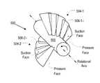
- FIG. 5depicts an embodiment of an impeller comprising bladelets in accordance with the illustrative embodiment of the present invention.
- the bladeletsexhibit a “tape-measure” geometry, wherein one side of each bladelet is concave and the other is convex.
- FIG. 6depicts further detail of a bladelet exhibiting tape-measure geometry in accordance with present teachings.
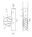
- FIG. 7depicts an embodiment of an impeller similar to FIG. 5 and wherein the bladelets of the blade are in a folded or delivery state.
- FIG. 8Adepicts an embodiment of an impeller in accordance with the present teachings, wherein a blade, which comprises a plurality of bladelets, is covered by a membrane.
- FIG. 8Bdepicts an embodiment of an impeller in accordance with the present teachings, wherein a membrane connects adjacent bladelets of an impeller blade.
- FIG. 9Adepicts a blood pump that incorporates an expandable impeller in accordance with the present teachings.
- the blood pumpis shown in an operational state in which the impeller is deployed or unfolded.
- FIG. 9Bdepicts the blood pump of FIG. 9A , wherein the blood pump is shown in a collapsed or delivery state in which the impeller is folded.
- Bladeletmeans a discrete segment of an impeller blade; that is, a plurality of bladelets compose a single impeller blade. Tips of adjacent bladelets abut one another or overlap. (Non-traditional definition.)
- Blade rowis a grouping of impeller blades that have a similar axial position along a hub and are typically equally circumferentially spaced apart.
- FIGS. 1A and 1Bdepict conventional impellers with blades arranged in blade rows.
- FIG. 1Adepicts impeller 100 A, which has four blades 104 that are grouped into a single blade row 106 on hub 102 .
- Blades 104are relatively long in span and short in chord, like those of an airplane propeller.
- FIG. 1Bdepicts impeller 100 B having hub 112 that supports two blades rows 120 and 124 each having two impeller blades.
- Blades 114 - 1 and 114 - 2are arranged in blade row 120 .
- blades 118 - 1 and 118 - 2are arranged in blade row 124 .
- the blades in blade rows 120 and 124are long helical blades that exhibit a significant degree of wrap around hub 112 .
- blades within a given blade rowcan exhibit a slight axial offset with respect to each other.
- leading edge 126 - 1 of blade 114 - 1is forward of leading edge 126 - 2 of blade 114 - 2 .
- Chordor (“chord length”) is a straight line (or the length thereof) connecting the leading and trailing edges of a blade or bladelet.
- Helixor “helical” means the curve formed by a straight (or curved) line drawn on a plane when that plane is wrapped around a cylindrical (or conical) surface of any kind, especially a right circular cylinder, as the curve of a (variable-pitch) screw.
- Multi-stage Pumpmeans a pump having an impeller having blade rows of rotating blades that are interspersed between blade rows of stator (non-rotating) blades that are attached to a housing.
- statornon-rotating blades
- the flow pathproceeds from rotor to stator (i.e., from one stage to the next) changing direction and using its momentum from the multiple changes in velocity and direction to achieve higher pressure head.
- Pressure facemeans, in the context of an impeller blade or bladelet, the pump-discharge-side face.
- Rootmeans, in the context of an impeller blade or bladelet, the portion thereof nearest to the hub.
- “Suction face”means, in the context of an impeller blade or bladelet, the pump-inlet-side face.
- Tipmeans, in the context of an impeller blade or bladelet, the portion furthest from the hub.
- FIG. 2Adepicts impeller 200 in accordance with the illustrative embodiment of the present invention.
- Impeller 200has hub 202 that supports blade 204 .
- Embodiments of an impeller in accordance with the present teachingswill usually, but not necessarily, include at least two blades. This is particularly important for impellers that are intended to rotate at speeds of thousands of rpm, such as is required for a percutaneously-inserted blood pump. Impeller 200 can be assumed to possess a second blade, which is not shown for the sake of clarity.
- Blade 204comprises a plurality of bladelets 206 - i .
- blade 204includes five bladelets.
- fewer bladelets or more bladeletsmay suitably be used as a function, for example, of the chord length of blade. More particularly, a blade having a relatively longer chord length will generally have more bladelets than a blade having a relatively shorter chord length.
- Each bladelet 206 - iis characterized as having root 208 , tip 210 , leading edge periphery 212 and trailing edge periphery 214 .
- the distance between root 208 and tip 210depicts the span of the bladelet.
- the distance between leading edge periphery 212 and trailing edge periphery 214depicts the extent of bladelet 206 - i in the chord-wise direction.
- the ratio of the chord of tip 210 to the chord of root 208 of each bladeletis typically in a range from about 1 to about 4, and more typically in a range from about 1.5 to about 3.
- the ratio of the span of a bladelet to the chord length of tip 210 of a bladeletis typically in a range from about 1 to about 4, and more typically in a range from about 2 to about 4.
- the ratio of the span of bladelet 206 - i to the diameter of hub 202is typically in a range from about 0.5 to about 3, and more typically in a range from about 1 to about 2.
- adjacent bladeletsoverlap near tip 210 .
- the precise amount of overlapwill vary as a function of bladelet geometry; in particular the ratio of the chord length of tip 210 to the chord length of root 208 , among other parameters. The greater the ratio, the greater the overlap, as a function of the root spacing between adjacent bladelets.
- overlapis minimal, such that the trailing edge and leading edge at tip 210 of adjacent bladelets simply abut each other. But in all embodiments in accordance with the present teachings, there must be at least minimal contact at the tip of adjacent bladelets. This ensures that the bladelets collectively define a single blade. If space is present between adjacent bladelets, then those bladelets are part of two different blades in two different blade rows.
- bladelets 206 - iare foldable.
- FIG. 2Acan be considered to depict the bladelets in an unfolded or deployed state and FIG. 2B shows the bladelets in a folded or delivery state. As depicted in FIG. 2B , bladelets 206 - i fold at location 216 near root 208 .
- FIGS. 2 A/ 2 Bsee also FIGS. 5 and 7
- an impellermight appear as a “right-handed” screw in one Figure and as a “left-handed” screw in what appears to be a complementary Figure.
- This apparent “inconsistency”is inconsequential since it is not germane to the purpose of the illustrations and will not cause any confusion for those skilled in the art.
- the bladeletsare formed from a material that is characterized by a resilience or an ability to return to a specific configuration once a restraining force that is deforming the bladelets is withdrawn.
- the bladeletscan be folded by advancing conduit 218 (e.g., catheter, etc.) over hub 202 and the bladelets. In this folded state, the collapsed diameter of impeller 200 is not substantially larger than the diameter of hub 202 .
- BladeletsWhen conduit 218 is withdrawn, the bladelets unfold (via the potential energy stored in the bladelets during the folding process). Bladelets having an ability to fold and unfold are particularly useful in conjunction with percutaneously-inserted blood pumps.
- An embodiment of blood pump utilizing an impeller in accordance with the present teachingsis described later in this disclosure.
- Foldable bladeletscan suitably be formed from superelastic Nitinol, stainless steel, or various polymers, such as polyimide, polypropylene, and the like.
- Hub 202is suitably formed from stainless steel, nitinol, or any of a variety of polymers.
- blade 204The geometry (e.g., chord, etc.) of blade 204 is application specific. For most applications, blade 204 will wrap at least partially around hub 202 along a helical path. For use in an expandable blood pump, blade 204 will wrap around hub 202 over an angle that is typically in the range of about 30 to 90 degrees. But, as a function of application specifics, blade 204 can wrap a full 360 degrees or more.
- FIG. 3depicts impeller 300 , wherein blade 304 comprising a plurality of bladelets 306 - i wraps over 180 degrees about hub 302 .
- blade rowmost impellers, and particularly those intended to operate at high rotational speeds, will typically have at least two blades that are equally circumferentially spaced-apart about the impeller hub. That is, the impeller (or blade row) will exhibit n-fold symmetry such that the blades are positioned about 360/n degrees apart from each other about the circumference of the hub, wherein n is the total number of blades in the blade row.
- FIGS. 4A and 4Bdepict two examples of impellers in accordance with the present teachings that display n-fold symmetry.
- FIG. 4Adepicts an end view of impeller 400 A having two blades 404 - 1 and 404 - 2 , each comprising a plurality of bladelets 406 - 1 - i and 406 - 2 - i , respectively.
- Blades 404 - 1 and 404 - 2are spaced 360/n degrees apart, where n equals 2, or 180 degrees apart about hub 402 A.
- FIG. 4Adepicts an end view of impeller 400 A having two blades 404 - 1 and 404 - 2 , each comprising a plurality of bladelets 406 - 1 - i and 406 - 2 - i , respectively.
- Blades 404 - 1 and 404 - 2are spaced 360/n degrees apart, where n equals 2, or 180 degrees apart about hub 402 A.
- FIG. 4Bdepicts an end view of impeller 400 B having three blades 404 - 1 , 404 - 2 , and 404 - 3 , each comprising a plurality of bladelets 406 - 1 - i , 406 - 2 - i , and 406 - 3 - i , respectively.
- Blades 404 - 1 , 404 - 2 , and 404 - 3are disposed 360/n degrees apart, where n equals 3, or 120 degrees apart about hub 402 B.
- FIG. 5depicts impeller 500 in accordance with a variation of the illustrative embodiment.
- Impeller 500includes two blades 504 - 1 and 504 - 2 that are organized into a single blade row about hub 502 .
- blade 504 - 1comprises a plurality of overlapping bladelets 506 - 1 - i
- blade 504 - 2comprises a plurality of overlapping bladelets 506 - 2 - i .
- each bladecomprises five bladelets.
- impeller 500The operational rotational direction of impeller 500 is indicated by the arrow in FIG. 5 (i.e., counterclockwise).
- the fluid to be pumpedis flowing “out of the page.”
- the pressure face of each bladelet 506 - 1 - i in blade 504 - 1is the “visible” face (in FIG. 5 ).
- the suction face of bladelets 506 - 1 - iis the obscured face.
- the pressure face of each bladelet 506 - 2 - i in blade 504 - 2is the “visible” face and the suction face is the obscured face.
- the pressure face of the bladeletsis concave and the suction face of the bladelets is convex.
- the concave face of the bladeletsis the leading face (i.e., the face that is pushing through the fluid).
- this geometryis analogous to that of a metallic wind-up tape measure.
- a tape measurecan be extended many feet against gravity, yet remain substantially straight if the tape is in a concave-side-up orientation. In this orientation, the concave side of the tape measure is exposed to the load (i.e., gravity). If, however, the tape measure is inverted, so that it assumes a concave-side-down orientation, the tape will readily succumb to gravity and buckle and fold. In this manner, the curvature of the tape measure provides rigidity against buckling/folding when exposed to loads, but only in one direction.
- bladelets 506 - 1 - i and 506 - 2 - i depicted in FIG. 5provide the same one-way rigidity when exposed to a load, such as the mass of the fluid being pumped. But it is critical that the pressure face is concave.
- FIG. 6depicts additional detail of an individual bladelet, which is representative of bladelets 506 - 1 - i and 506 - 2 - i .
- Other bladelets that would normally be present to collectively define a bladeare not depicted in FIG. 6 for the sake of clarity.
- the bladelet depicted in FIG. 6is characterized by root 608 , tip 610 , edge 612 and edge 614 .
- Face 620is concave and face 622 is convex.
- the ratio of the chord length of tip 610 to the chord length of root 608 of each concave/convex bladeletis typically in a range from about 1 to about 4, and more typically in a range from about 1.5 to about 3.
- the ratio of the span of a bladelet to the chord length of tip 610 of a bladeletis typically in a range from about 1 to about 4, and more typically in a range from about 1.5 to about 4.
- the ratio of the span of a bladelet to the diameter of hub 602is typically in a range from about 0.5 to about 3, and more typically in a range from about 1 to about 2.
- the radius of curvature of root 608is typically in a range of about 0.2 to about 2.5 times the chord length of the root. This equates to curvature for root 608 that is in a range of about 12 degrees to about 150 degrees. More typically, the curvature of root 608 will be within the range of about 30 degrees to about 60 degrees.
- adjacent bladelets 506 - 1 - i in blade 504 - 1overlap near the tips thereof.
- adjacent bladelets 506 - 2 - i in blade 504 - 2overlap near the tips thereof.
- the precise amount of overlapwill vary as a function of bladelet geometry; in particular the ratio of the chord length of tip 610 ( FIG. 6 ) to the chord length of root 608 , among other parameters. The greater the ratio, the greater the overlap, as a function of the root spacing between adjacent bladelets. In some embodiments, overlap is minimal, such that the trailing edge and leading edge at the tip of adjacent bladelets simply abut each other.
- the concave/convex bladelets disclosed hereinare foldable, like bladelets 206 - i .
- FIG. 5can be considered to depict the bladelets of an impeller in an unfolded or deployed state and
- FIG. 7shows bladelets of an impeller in a folded or delivery state.
- the concave/convex bladeletsare formed from a material that is characterized by a resilience or an ability to return to a specific configuration once a restraining force that is deforming the bladelets is withdrawn.
- Foldable bladeletscan suitably be formed from superelastic Nitinol, stainless steel, or various polymers, such as polyimide, polypropylene, and the like.
- foldable concave/convex bladeletscan be folded by advancing conduit 728 (e.g., catheter, etc.) over hub 702 and bladelets 706 - 1 - i of blade 706 - 1 and 706 - 2 -I of blade 706 - 2 . (Most of the bladelets of blade 706 - 2 are obscured.)
- conduit 728is withdrawn, the bladelets unfold via the potential energy stored in the bladelets during the folding process.
- FIGS. 8A and 8Bdepict two embodiments of impellers with membranes.
- FIG. 8Adepicts impeller 800 A having membrane 830 that completely encapsulates blade 804 and all bladelets 806 - i .
- the membranecan either be bonded to the root of each bladelet or to hub 802 near the root.
- FIG. 8Bdepicts impeller 800 B wherein membrane 840 is implemented as a webbing that is disposed between opposing peripheral edges of adjacent bladelets 806 - i .
- membrane 840covers only a portion of blade 804 whereas for the embodiment depicted in FIG. 8A , membrane 830 covers the full blade.
- the membranemay be formed from polyurethane, silicone, latex rubber, other elastomeric compounds, or a biologic membrane such as bovine pericardium.
- FIGS. 9A and 9Bdepict the pump-assembly portion 950 of a temporary cardiac assist device or blood pump, as is suitable for percutaneous insertion into the vascular system of a patient.
- pump assembly 950is intended for percutaneous insertion, it is advantageously sized so that it can be introduced into the vascular system (e.g., Femoral artery, etc.) via a 12-French or smaller-diameter catheter. Historically, it has been difficult to achieve average flows greater than about 2 to 2.5 liters per minute against physiologic pressures through a 12-French catheter, which has a diameter of 4 millimeters. To that end, pump assembly 950 is collapsed for insertion and delivery, as depicted in FIG. 9B , and expanded for pumping (as depicted in FIG. 9A ) when it reaches its intended deployment site.
- vascular systeme.g., Femoral artery, etc.
- Pump assembly 950includes proximal support housing 952 , impeller 900 , distal support 954 , nose cone 956 , casing 960 , proximal support ring 962 , and distal support ring 964 .
- Pump assembly 950is based on a design for a percutaneously-inserted, expandable, cardiac-assist device that was disclosed in U.S. Published Pat. Application 2008/0132747, incorporated by reference herein. Pump assembly 950 departs from that design by incorporating an impeller having a plurality of overlapping bladelets as disclosed herein. That document can be referenced for additional information concerning the pump assembly design.
- Impeller 900comprises impeller hub 902 and two impeller blades 904 - 1 and 904 - 2 that are arranged in a single blade row. Each impeller blade comprises a plurality of overlapping bladelets 906 - 1 - i and 906 - 2 - i.
- a plurality of spaced-apart ribs 958are axisymmetrically arranged about central axis A-A of pump assembly 950 .
- the ribscollectively define cage or casing 960 .
- the ribsexhibit an arcuate shape, so that open, cage-like casing 960 adopts a typically ellipsoidal or prolate-spheroid form.
- the casingexhibits its maximum diameter. This maximum or enlarged diameter is required to accommodate impeller blades 904 - 1 and 904 - 2 when they are deployed for operation.
- Casing 960provides one or more of the following functions:
- a membrane(not depicted for reasons of clarity) covers a portion of casing 960 ; the end regions of the casing remain uncovered.
- the purpose of the membraneis to channel or confine the blood in the vicinity of impeller blades 904 - 1 and 904 - 2 so that a flow field develops. Blood enters and exits pump assembly 950 through the uncovered regions of the casing.
- the membraneis formed from polyurethane, silicone, latex rubber, or other elastomeric compounds.
- ribs 958are formed in such a way (e.g., processing, materials of fabrication, etc.) that in the absence of a restraining force, they exhibit the aforementioned non-planar (e.g., arcuate, etc.) shape, such that pump assembly 950 “naturally” assumes the expanded configuration. As a consequence, no actuating force is required to place pump assembly 950 into its operating configuration. Rather, for such embodiments, a force must be applied to restrain pump assembly 950 from expanding.
- a super-elastic materialsuch as nitinol, etc., can be used to form ribs 952 .
- Elements of pump assembly 950are coaxial and, in some cases, linearly arranged with respect to one another. This provides stability to pump assembly 950 .
- proximal support housing 952 , impeller hub 902 , and distal support 954are linearly arranged.
- Proximal support housing 952 and impeller hub 902are coaxial with respect to drive shaft 948 .
- Casing 960which comprises ribs 958 , proximal support ring 962 , and distal support ring 964 , is coaxial with respect to proximal support housing 952 , impeller hub 902 , and distal support 954 .
- proximal support housing 952 , impeller hub 902 , and distal support 954comprise injection molded polymer.
- the proximal end of the drive cableis coupled to the motor and the distal end of the drive cable is coupled to drive shaft 948 .
- the drive shaftenters the proximal end of pump assembly 950 and is operatively coupled to impeller hub 902 .
- the drive shaftextends a relatively short distance (less than about 3 centimeters) proximal of pump assembly 950 .
- the drive cable and the drive shaftare distinct components and the distinction between them is an important one.
- the drive cablemust be flexible to enable it to be easily advanced in the vasculature and, if required, beyond the aortic arch.
- drive shaft 948is rigid in order that the requisite seal and bearing in proximal support housing 952 function properly.
- drive shaft 948passes through proximal support housing 952 to impeller hub 902 and terminates therein. In some embodiments, the drive shaft terminates approximately at the axial mid-point of impeller hub 902 .
- Proximal support housing 952provides a non-rotating support surface for the proximal support ring 962 , thereby supporting the proximal end of casing 960 . Since casing 960 does not rotate, it cannot couple to a rotating surface, such as impeller hub 902 .
- proximal support housing 952does not rotate but impeller hub 902 does, they are separated by gap. And since drive shaft 948 passes through proximal support housing 952 , a bearing must be provided within the housing to accommodate the rotational movement of drive shaft 948 . A seal must also be provided within proximal support housing 952 to prevent blood from entering. If blood were to enter housing 952 in the small gap between drive shaft 948 and the bore that accepts it, the blood might be hemolyzed by the action of drive shaft 948 .
- the bore of the bearing within proximal support housing 952provides substantially all of the structural rigidity for impeller blades 904 - 1 and 904 - 2 /impeller hub 902 .
- Materials suitable for the bearinginclude, without limitation, low friction polymers, such as Teflon® (polytetrafluoroethylene), Torlon® (polyamide-imide), Rulon® (propriety polytetrafluoroethylene-based compounds), Vespel® (thermoplastic polyimide) sleeve bearings, biocompatible bearings and the like.
- low friction polymerssuch as Teflon® (polytetrafluoroethylene), Torlon® (polyamide-imide), Rulon® (propriety polytetrafluoroethylene-based compounds), Vespel® (thermoplastic polyimide) sleeve bearings, biocompatible bearings and the like.
- polyurethane or silicon lip seals or o-ringsare used as the seal.
- drive shaft 948is formed as an integral part of impeller hub 902 .
- impeller hub 902is formed around drive shaft 948 .
- drive shaft 948is rigidly coupled to impeller hub 902 to efficiently drive the impeller blades.
- Drive shaft 948is formed of stainless steel or other materials having specific dimensions, hardness, surface finish, and radiused edges for damage-free seal insertion. Surface finish will be specified by the bearing or seal manufacturer to ensure compatibility with same.
- the drive cable(not shown) is formed of stainless steel (but in such a way that the cable remains flexible). In some embodiments, the drive cables disclosed in U.S. patent application Ser. No. 11/758,402 are used.
- Impeller blades 904 - 1 and 904 - 2are depicted in a deployed or unfolded state in FIG. 9A . In this state, they extend substantially orthogonally from impeller hub 902 .
- the impeller bladescomprise a plurality of bladelets, consistent with embodiments described earlier in this disclosure.
- the bladeletshave concave pressure side and a convex suction side, as per impeller 500 of FIG. 5 .
- the bladelets of impeller blades 904 - 1 and 904 - 2are biased to deploy; that is, they must be restrained to be kept in the folded state.
- the bladeletsare formed of a resilient material, as previously described.
- the bladeletsmust be “spun-up” to the deployed state. In other words, the rotation of the impeller hub causes the bladelets to deploy.
- impeller 900In a collapsed state, impeller 900 has a diameter of about 3 millimeters (9 Fr).
- the design speed of the impelleris in the range of between about 1,000 RPM to about 20,000 RPM.
- the impelleris expected to pump at least 2.5 liters per minute of blood at 100 mmHg (4 cP) and 37° C. using a 10 Fr delivery system.
- the impelleris designed for a 100% duty cycle for a seven-day service life.
- Casing 960is advantageously supported at its distal end. Such support is provided by distal support 954 , which receives distal support ring 964 . Like proximal support housing 952 , the distal support is not rotating. Since, however, impeller hub 902 is rotating, the impeller hub and distal support 954 are separated by a gap. Because drive shaft 948 does not extend beyond the impeller blades, a locating pin or other means is required to couple distal support 954 to impeller hub 902 .
- locating pin 953depends from proximal end of distal support 954 .
- the pincouples the proximal end of the distal support to the distal end of impeller hub 902 .
- Disposed within the distal end of impeller hub 902are a bearing and seal (not depicted). Since, as previously disclosed, impeller hub 902 is rotating and distal support 954 is not, a bearing is required to accommodate the differential movement. And the seal prevents leakage of blood into impeller hub 902 .
- the bearing and seal in the impeller hubare formed of the same materials as the bearing and seal in proximal support housing 952 .
- distal support 954terminates in nose cone 956 , which provides an atraumatic surface that is contoured for easy insertion and navigation through a patient's vascular system.
- FIG. 9Bdepicts pump assembly 950 in its delivery state.
- casing 960and pump assembly 950 ) exhibits its minimum diameter.
- ribs 952are straight and substantially parallel to axis A-A of pump assembly 950 .
- Casing 960adopts a substantially cylindrical shape.
- pump assembly 950has a relatively smaller diameter, the task of negotiating the vascular system, and in particular the aortic arch, is simplified. As a consequence, pump assembly 950 is introduced into the body (e.g., the femoral artery, etc.) in the folded or delivery state. Typically, it is after pump assembly 950 has passed the aortic arch and entered the ascending aorta or other final locations that casing 960 is expanded for operation.
- bodye.g., the femoral artery, etc.
- pump assembly 950is deployed into the vascular system via an “introducing” tube, such as a catheter, sheath, or the like.
- the wall of the introducing tubeprovides the restraining force to maintain casing 960 in the contracted state.
- pump assembly 950is simply advanced beyond the distal end of the tube.
- the introducing tubemust possess a suitably radially-inelastic wall. Standard catheters are suitably radially-inelastic for this purpose. In conjunction with the present disclosure, it is within the capabilities of those skilled in the art to provide an introducing tube having a suitably radially-inelastic wall to maintain casing 960 in the contracted state.
- One of either the proximal end or the distal end of casing 960is movable in an axial direction. This facilitates the expansion and contraction of the casing.
- casing 960is to be collapsed simply by the act of inserting the proximal end of pump assembly 950 into an introduction/extraction catheter, then it is advantageous (but not necessary) for the distal end of casing 960 to be the movable end.
- distal support ring 964is movably coupled to distal support 964 so that it is able to readily slide along the support in either direction.
- Pump assembly 950may be collapsed as follows for extraction from the vascular system.
- impeller 900is rotated slowly in the reverse direction, such that the convex face of the bladelets becomes the pressure face.
- the bladeletswill readily collapse once the convex side is exposed to a load. Pump assembly is then drawn back into the introducing tube.
- the bladeletsmight or might not remain collapsed (after the cessation of reverse impeller rotation).
- the pump assemblyis drawn back into the introducing tube while the impeller is still in motion.
- the reverse rotational motionis stopped only after the pump assembly is within the introducing tube, wherein the wall of the tube will maintain the bladelets in the collapsed state.
- impeller rotationis simply stopped and pump assembly 950 is drawn back into the introducing tube.
- One benefit of the curved structure of the bladeletsis that, even though the “closure” force is being applied to the side that is best able to resist it, once the buckling force is exceeded, the bladelets will readily fold and collapse against hub 902 .
Landscapes
- Engineering & Computer Science (AREA)
- Health & Medical Sciences (AREA)
- Heart & Thoracic Surgery (AREA)
- Mechanical Engineering (AREA)
- Hematology (AREA)
- Cardiology (AREA)
- Anesthesiology (AREA)
- Biomedical Technology (AREA)
- General Engineering & Computer Science (AREA)
- Life Sciences & Earth Sciences (AREA)
- Animal Behavior & Ethology (AREA)
- General Health & Medical Sciences (AREA)
- Public Health (AREA)
- Veterinary Medicine (AREA)
- Vascular Medicine (AREA)
- External Artificial Organs (AREA)
- Structures Of Non-Positive Displacement Pumps (AREA)
Abstract
Description
- one or more blades that are segmented into a plurality of overlapping/abutting bladelets; and/or
- a membrane covers the blade(s); and/or
- bladelets in which the pressure face is concave; and/or
- bladelets in which the suction face is convex; and/or
- foldable bladelets; and/or
- the chord length of the root of a bladelet is smaller than the chord length of the tip of the bladelet; and/or
- the radius of curvature of the root of a bladelet is smaller than the radius of curvature of the tip of the bladelet.
By way of example, but not limitation, alternative contemplated impeller designs in accordance with the present teachings include impellers having: - One or more blades that are segmented into a plurality of overlapping/abutting bladelets that are not foldable and do not have a pressure face that is concave.
- One or more blades that are segmented into a plurality of overlapping/abutting bladelets that are foldable and do not have a pressure face that is concave.
- One or more blades that are segmented into a plurality of overlapping/abutting bladelets that are not foldable and do have a pressure face that is concave.
- A single blade that is foldable and has a pressure face that is concave.
- it prevents the spinning impeller blades of
pump assembly 950 from contacting anatomical features; - it establishes structural integrity;
- it provides a framework for an overlying membrane.
- it prevents the spinning impeller blades of
- Diameter of impeller hub902: about 2 millimeters (mm)
- Span of impeller bladelets906-1-i/906-2-i:about 3 mm
- Chord length of bladelets at the root: about 1 mm
- Chord length of bladelets at the tip: about 2 mm
- Bladelets per blade904-1/904-2: typically 3-7
- Radius of curvature of bladelets at root: about 1 mm
- Radius of curvature of bladelets at tip: greater than 2 mm
Claims (30)
Priority Applications (6)
| Application Number | Priority Date | Filing Date | Title |
|---|---|---|---|
| US12/201,561US8079948B2 (en) | 2007-08-29 | 2008-08-29 | Article comprising an impeller |
| AU2008292775AAU2008292775B2 (en) | 2007-08-29 | 2008-09-11 | Article comprising an impeller |
| EP08828374.2AEP2185822B1 (en) | 2007-08-29 | 2008-09-11 | Article comprising an impeller |
| PCT/US2008/075993WO2009029959A2 (en) | 2007-08-29 | 2008-09-11 | Article comprising an impeller |
| JP2010523203AJP5449164B2 (en) | 2007-08-29 | 2008-09-11 | Device having an impeller |
| US13/283,181US8371997B2 (en) | 2007-08-29 | 2011-10-27 | Article comprising an impeller II |
Applications Claiming Priority (2)
| Application Number | Priority Date | Filing Date | Title |
|---|---|---|---|
| US96886407P | 2007-08-29 | 2007-08-29 | |
| US12/201,561US8079948B2 (en) | 2007-08-29 | 2008-08-29 | Article comprising an impeller |
Related Child Applications (1)
| Application Number | Title | Priority Date | Filing Date |
|---|---|---|---|
| US13/283,181ContinuationUS8371997B2 (en) | 2007-08-29 | 2011-10-27 | Article comprising an impeller II |
Publications (2)
| Publication Number | Publication Date |
|---|---|
| US20090062597A1 US20090062597A1 (en) | 2009-03-05 |
| US8079948B2true US8079948B2 (en) | 2011-12-20 |
Family
ID=40408559
Family Applications (2)
| Application Number | Title | Priority Date | Filing Date |
|---|---|---|---|
| US12/201,561Active2030-08-06US8079948B2 (en) | 2007-08-29 | 2008-08-29 | Article comprising an impeller |
| US13/283,181ActiveUS8371997B2 (en) | 2007-08-29 | 2011-10-27 | Article comprising an impeller II |
Family Applications After (1)
| Application Number | Title | Priority Date | Filing Date |
|---|---|---|---|
| US13/283,181ActiveUS8371997B2 (en) | 2007-08-29 | 2011-10-27 | Article comprising an impeller II |
Country Status (5)
| Country | Link |
|---|---|
| US (2) | US8079948B2 (en) |
| EP (1) | EP2185822B1 (en) |
| JP (1) | JP5449164B2 (en) |
| AU (1) | AU2008292775B2 (en) |
| WO (1) | WO2009029959A2 (en) |
Cited By (70)
| Publication number | Priority date | Publication date | Assignee | Title |
|---|---|---|---|---|
| US8376707B2 (en) | 2004-09-17 | 2013-02-19 | Thoratec Corporation | Expandable impeller pump |
| US20130177409A1 (en)* | 2010-07-15 | 2013-07-11 | Ecp Entwicklungsgesellschaft Mbh | Rotor for a pump, produced with a first elastic material |
| US8485961B2 (en) | 2011-01-05 | 2013-07-16 | Thoratec Corporation | Impeller housing for percutaneous heart pump |
| US8535211B2 (en) | 2009-07-01 | 2013-09-17 | Thoratec Corporation | Blood pump with expandable cannula |
| WO2013173245A1 (en)* | 2012-05-14 | 2013-11-21 | Thoratec Corporation | Impeller for catheter pump |
| US8591393B2 (en) | 2011-01-06 | 2013-11-26 | Thoratec Corporation | Catheter pump |
| US8597170B2 (en) | 2011-01-05 | 2013-12-03 | Thoratec Corporation | Catheter pump |
| WO2014143593A1 (en)* | 2013-03-15 | 2014-09-18 | Thoratec Corporation | Catheter pump assembly including a stator |
| US9138518B2 (en) | 2011-01-06 | 2015-09-22 | Thoratec Corporation | Percutaneous heart pump |
| US20160053763A1 (en)* | 2009-06-25 | 2016-02-25 | Ecp Entwicklungsgesellschaft Mbh | Compressible and expandable blade for a fluid pump |
| US9308302B2 (en) | 2013-03-15 | 2016-04-12 | Thoratec Corporation | Catheter pump assembly including a stator |
| US9314558B2 (en) | 2009-12-23 | 2016-04-19 | Ecp Entwicklungsgesellschaft Mbh | Conveying blades for a compressible rotor |
| US20160106896A1 (en)* | 2007-10-08 | 2016-04-21 | Ais Gmbh Aachen Innovative Solutions | Catheter device |
| US9327067B2 (en) | 2012-05-14 | 2016-05-03 | Thoratec Corporation | Impeller for catheter pump |
| US9339596B2 (en) | 2009-12-23 | 2016-05-17 | Ecp Entwicklungsgesellschaft Mbh | Radially compressible and expandable rotor for a fluid pump |
| US9358329B2 (en) | 2012-07-03 | 2016-06-07 | Thoratec Corporation | Catheter pump |
| US9364593B2 (en) | 2004-09-17 | 2016-06-14 | The Penn State Research Foundation | Heart assist device with expandable impeller pump |
| US9381288B2 (en) | 2013-03-13 | 2016-07-05 | Thoratec Corporation | Fluid handling system |
| US9404505B2 (en) | 2008-12-05 | 2016-08-02 | Ecp Entwicklungsgesellschaft Mbh | Fluid pump with a rotor |
| US9416783B2 (en) | 2009-09-22 | 2016-08-16 | Ecp Entwicklungsgellschaft Mbh | Compressible rotor for a fluid pump |
| US9416791B2 (en) | 2010-01-25 | 2016-08-16 | Ecp Entwicklungsgesellschaft Mbh | Fluid pump having a radially compressible rotor |
| US9421311B2 (en) | 2012-07-03 | 2016-08-23 | Thoratec Corporation | Motor assembly for catheter pump |
| US9446179B2 (en) | 2012-05-14 | 2016-09-20 | Thoratec Corporation | Distal bearing support |
| US9611743B2 (en) | 2010-07-15 | 2017-04-04 | Ecp Entwicklungsgesellschaft Mbh | Radially compressible and expandable rotor for a pump having an impeller blade |
| US9675739B2 (en) | 2015-01-22 | 2017-06-13 | Tc1 Llc | Motor assembly with heat exchanger for catheter pump |
| US9675738B2 (en) | 2015-01-22 | 2017-06-13 | Tc1 Llc | Attachment mechanisms for motor of catheter pump |
| US9770543B2 (en) | 2015-01-22 | 2017-09-26 | Tc1 Llc | Reduced rotational mass motor assembly for catheter pump |
| US9827356B2 (en) | 2014-04-15 | 2017-11-28 | Tc1 Llc | Catheter pump with access ports |
| US9872947B2 (en) | 2012-05-14 | 2018-01-23 | Tc1 Llc | Sheath system for catheter pump |
| US9907890B2 (en) | 2015-04-16 | 2018-03-06 | Tc1 Llc | Catheter pump with positioning brace |
| US9913937B2 (en) | 2013-03-13 | 2018-03-13 | Magenta Medical Ltd. | Renal pump |
| US10029037B2 (en) | 2014-04-15 | 2018-07-24 | Tc1 Llc | Sensors for catheter pumps |
| US10080871B2 (en) | 2012-12-21 | 2018-09-25 | Ecp Entwicklungsgesellschaft Mbh | Sheath assembly for insertion of a cord-shaped element, particularly a catheter, into the body of a patient |
| US10105475B2 (en) | 2014-04-15 | 2018-10-23 | Tc1 Llc | Catheter pump introducer systems and methods |
| US10213580B2 (en) | 2013-12-11 | 2019-02-26 | Magenta Medical Ltd | Curved catheter |
| US10299918B2 (en) | 2012-06-06 | 2019-05-28 | Magenta Medical Ltd. | Vena-caval device |
| US10350341B2 (en) | 2015-03-20 | 2019-07-16 | Drexel University | Impellers, blood pumps, and methods of treating a subject |
| US10525238B2 (en) | 2011-12-22 | 2020-01-07 | Ecp Entwicklungsgesellschaft Mbh | Sheath device for inserting a catheter |
| US20200040907A1 (en)* | 2018-08-02 | 2020-02-06 | Percheron Power, LLC | Screw systems |
| US10583231B2 (en) | 2013-03-13 | 2020-03-10 | Magenta Medical Ltd. | Blood pump |
| US10583232B2 (en) | 2014-04-15 | 2020-03-10 | Tc1 Llc | Catheter pump with off-set motor position |
| US10709828B2 (en) | 2011-12-22 | 2020-07-14 | Ecp Entwicklungsgesellschaft Mbh | Sheath device for inserting a catheter |
| US10722631B2 (en) | 2018-02-01 | 2020-07-28 | Shifamed Holdings, Llc | Intravascular blood pumps and methods of use and manufacture |
| US10874783B2 (en) | 2007-10-08 | 2020-12-29 | Ais Gmbh Aachen Innovative Solutions | Catheter device |
| US10881770B2 (en) | 2018-01-10 | 2021-01-05 | Magenta Medical Ltd. | Impeller for blood pump |
| US10893927B2 (en) | 2018-03-29 | 2021-01-19 | Magenta Medical Ltd. | Inferior vena cava blood-flow implant |
| US11033727B2 (en) | 2016-11-23 | 2021-06-15 | Magenta Medical Ltd. | Blood pumps |
| US11039915B2 (en) | 2016-09-29 | 2021-06-22 | Magenta Medical Ltd. | Blood vessel tube |
| US11077294B2 (en) | 2013-03-13 | 2021-08-03 | Tc1 Llc | Sheath assembly for catheter pump |
| US11185677B2 (en) | 2017-06-07 | 2021-11-30 | Shifamed Holdings, Llc | Intravascular fluid movement devices, systems, and methods of use |
| US11191944B2 (en) | 2019-01-24 | 2021-12-07 | Magenta Medical Ltd. | Distal tip element for a ventricular assist device |
| US11219756B2 (en) | 2012-07-03 | 2022-01-11 | Tc1 Llc | Motor assembly for catheter pump |
| US11229786B2 (en)* | 2012-05-14 | 2022-01-25 | Tc1 Llc | Impeller for catheter pump |
| US11260212B2 (en) | 2016-10-25 | 2022-03-01 | Magenta Medical Ltd. | Ventricular assist device |
| US11291824B2 (en) | 2015-05-18 | 2022-04-05 | Magenta Medical Ltd. | Blood pump |
| US11291826B2 (en) | 2018-01-10 | 2022-04-05 | Magenta Medical Ltd. | Axially-elongatable frame and impeller |
| US11511103B2 (en) | 2017-11-13 | 2022-11-29 | Shifamed Holdings, Llc | Intravascular fluid movement devices, systems, and methods of use |
| US11654275B2 (en) | 2019-07-22 | 2023-05-23 | Shifamed Holdings, Llc | Intravascular blood pumps with struts and methods of use and manufacture |
| US11724089B2 (en) | 2019-09-25 | 2023-08-15 | Shifamed Holdings, Llc | Intravascular blood pump systems and methods of use and control thereof |
| US11850414B2 (en) | 2013-03-13 | 2023-12-26 | Tc1 Llc | Fluid handling system |
| US11964145B2 (en) | 2019-07-12 | 2024-04-23 | Shifamed Holdings, Llc | Intravascular blood pumps and methods of manufacture and use |
| US12102815B2 (en) | 2019-09-25 | 2024-10-01 | Shifamed Holdings, Llc | Catheter blood pumps and collapsible pump housings |
| US12121713B2 (en) | 2019-09-25 | 2024-10-22 | Shifamed Holdings, Llc | Catheter blood pumps and collapsible blood conduits |
| US12128228B2 (en) | 2019-05-23 | 2024-10-29 | Magenta Medical Ltd | Blood pumps |
| US12128227B2 (en) | 2020-04-07 | 2024-10-29 | Magenta Medical Ltd. | Manufacture of an impeller |
| US12161857B2 (en) | 2018-07-31 | 2024-12-10 | Shifamed Holdings, Llc | Intravascular blood pumps and methods of use |
| US12220570B2 (en) | 2018-10-05 | 2025-02-11 | Shifamed Holdings, Llc | Intravascular blood pumps and methods of use |
| US12350483B2 (en) | 2016-07-21 | 2025-07-08 | Tc1 Llc | Fluid seals for catheter pump motor assembly |
| US12409310B2 (en) | 2019-12-11 | 2025-09-09 | Shifamed Holdings, Llc | Descending aorta and vena cava blood pumps |
| US12440663B2 (en) | 2022-04-18 | 2025-10-14 | Magenta Medical Ltd. | Curved tube for a ventricular assist device |
Families Citing this family (41)
| Publication number | Priority date | Publication date | Assignee | Title |
|---|---|---|---|---|
| DE10336902C5 (en) | 2003-08-08 | 2019-04-25 | Abiomed Europe Gmbh | Intracardiac pumping device |
| US8690749B1 (en) | 2009-11-02 | 2014-04-08 | Anthony Nunez | Wireless compressible heart pump |
| EP2338539A1 (en)* | 2009-12-23 | 2011-06-29 | ECP Entwicklungsgesellschaft mbH | Pump device with a detection device |
| EP2388029A1 (en) | 2010-05-17 | 2011-11-23 | ECP Entwicklungsgesellschaft mbH | Pump array |
| EP2399639A1 (en) | 2010-06-25 | 2011-12-28 | ECP Entwicklungsgesellschaft mbH | System for introducing a pump |
| EP2407187A3 (en)* | 2010-07-15 | 2012-06-20 | ECP Entwicklungsgesellschaft mbH | Blood pump for invasive application within the body of a patient |
| US9162017B2 (en) | 2011-08-29 | 2015-10-20 | Minnetronix, Inc. | Expandable vascular pump |
| US8734331B2 (en)* | 2011-08-29 | 2014-05-27 | Minnetronix, Inc. | Expandable blood pumps and methods of their deployment and use |
| US8849398B2 (en) | 2011-08-29 | 2014-09-30 | Minnetronix, Inc. | Expandable blood pump for cardiac support |
| FR2981130B1 (en)* | 2011-10-10 | 2013-12-20 | Nsc Environnement | ARCHIMEDE SCREW AND INSTALLATION OF THE PUMP TYPE OR HYDROELECTRIC PLANT EQUIPPED WITH AT LEAST ONE SUCH SCREW |
| JP6139550B2 (en)* | 2011-11-28 | 2017-05-31 | ミ‐ヴァド インコーポレイテッド | Auxiliary circulation apparatus and method |
| US20120109191A1 (en)* | 2011-12-13 | 2012-05-03 | Vascular Insights Llc | Adhesive-based varicose vein treatment |
| EP2860849B1 (en) | 2013-10-11 | 2016-09-14 | ECP Entwicklungsgesellschaft mbH | Compressible motor, implanting assembly and method for positioning the motor |
| GB201410986D0 (en)* | 2014-06-20 | 2014-08-06 | Marine Flow Ltd | Flexible impeller pump |
| EP3583973A1 (en) | 2014-08-18 | 2019-12-25 | Tc1 Llc | Guide features for percutaneous catheter pump |
| EP3200846B1 (en) | 2014-10-01 | 2020-01-15 | Heartware, Inc. | Backup controller system with updating |
| EP3808401A1 (en) | 2016-07-21 | 2021-04-21 | Tc1 Llc | Gas-filled chamber for catheter pump motor assembly |
| EP3519008A4 (en) | 2016-10-03 | 2020-08-26 | Queen Mary University of London | MECHANICAL CIRCULATORY SUPPORT DEVICE WITH AXIAL FLOW TURBO MACHINE WITH OPTIMIZATION FOR HEART FAILURE AND HEART-KIDNEY SYNDROME |
| JP7150615B2 (en)* | 2017-01-18 | 2022-10-11 | テルモ株式会社 | blood pump |
| WO2018139508A1 (en)* | 2017-01-27 | 2018-08-02 | テルモ株式会社 | Impeller and blood pump |
| DE102017102823A1 (en)* | 2017-02-13 | 2018-08-16 | Cardiobridge Gmbh | Catheter pump with a pump head for insertion into the arterial vasculature |
| EP3630218A4 (en) | 2017-06-01 | 2021-05-12 | Queen Mary University of London | MECHANICAL CIRCULATORY ASSISTANCE DEVICE WITH CENTRIFUGAL IMPELLER, INTENDED TO BE IMPLANTED IN THE DESCENDING AORTA |
| DE102018201030B4 (en) | 2018-01-24 | 2025-10-16 | Kardion Gmbh | Magnetic dome element with magnetic bearing function |
| JP7566724B2 (en) | 2018-04-04 | 2024-10-15 | セオドシオス・アレクサンダー | Removable mechanical circulatory support units for short-term use |
| DE102018207575A1 (en) | 2018-05-16 | 2019-11-21 | Kardion Gmbh | Magnetic face turning coupling for the transmission of torques |
| DE102018207611A1 (en) | 2018-05-16 | 2019-11-21 | Kardion Gmbh | Rotor bearing system |
| DE102018208541A1 (en) | 2018-05-30 | 2019-12-05 | Kardion Gmbh | Axial pump for a cardiac assist system and method of making an axial pump for a cardiac assist system |
| DE102018208538A1 (en) | 2018-05-30 | 2019-12-05 | Kardion Gmbh | Intravascular blood pump and process for the production of electrical conductors |
| DE102018208539A1 (en) | 2018-05-30 | 2019-12-05 | Kardion Gmbh | A motor housing module for sealing an engine compartment of a motor of a cardiac assist system and cardiac assistance system and method for mounting a cardiac assist system |
| DE102018208550A1 (en) | 2018-05-30 | 2019-12-05 | Kardion Gmbh | A lead device for directing blood flow to a cardiac assist system, cardiac assist system, and method of making a lead device |
| DE102018210058A1 (en) | 2018-06-21 | 2019-12-24 | Kardion Gmbh | Stator blade device for guiding the flow of a fluid flowing out of an outlet opening of a heart support system, heart support system with stator blade device, method for operating a stator blade device and manufacturing method |
| DE102018210076A1 (en) | 2018-06-21 | 2019-12-24 | Kardion Gmbh | Method and device for detecting a state of wear of a cardiac support system, method and device for operating a cardiac support system and cardiac support system |
| DE102018211327A1 (en) | 2018-07-10 | 2020-01-16 | Kardion Gmbh | Impeller for an implantable vascular support system |
| DE102018212153A1 (en) | 2018-07-20 | 2020-01-23 | Kardion Gmbh | Inlet line for a pump unit of a cardiac support system, cardiac support system and method for producing an inlet line for a pump unit of a cardiac support system |
| US11541224B2 (en) | 2018-07-30 | 2023-01-03 | Cardiovascular Systems, Inc. | Intravascular pump without inducer and centrifugal force-driven expansion of impeller blades and/or expandable and collapsible impeller housing |
| CN112654389A (en) | 2018-08-07 | 2021-04-13 | 开迪恩有限公司 | Bearing device for a cardiac support system and method for flushing an intermediate space in a bearing device for a cardiac support system |
| DE102020102474A1 (en) | 2020-01-31 | 2021-08-05 | Kardion Gmbh | Pump for conveying a fluid and method for manufacturing a pump |
| CN113648533A (en)* | 2021-08-26 | 2021-11-16 | 复旦大学 | Transcatheter implantable flexible dual-lumen assist device to provide circulatory power to Fontan patients |
| CN114733062A (en)* | 2021-11-05 | 2022-07-12 | 苏州心擎医疗技术有限公司 | Ventricular assist device |
| CN115507054B (en)* | 2022-10-18 | 2025-06-24 | 深圳市兴日生实业有限公司 | A water pump |
| CN116085299B (en)* | 2023-01-18 | 2025-09-26 | 上海魅丽纬叶医疗科技有限公司 | A foldable composite rotary blade and medical power pump |
Citations (55)
| Publication number | Priority date | Publication date | Assignee | Title |
|---|---|---|---|---|
| US3510229A (en) | 1968-07-23 | 1970-05-05 | Maytag Co | One-way pump |
| US4625712A (en) | 1983-09-28 | 1986-12-02 | Nimbus, Inc. | High-capacity intravascular blood pump utilizing percutaneous access |
| US4753221A (en) | 1986-10-22 | 1988-06-28 | Intravascular Surgical Instruments, Inc. | Blood pumping catheter and method of use |
| US4817586A (en) | 1987-11-24 | 1989-04-04 | Nimbus Medical, Inc. | Percutaneous bloom pump with mixed-flow output |
| US4846152A (en) | 1987-11-24 | 1989-07-11 | Nimbus Medical, Inc. | Single-stage axial flow blood pump |
| US4919647A (en) | 1988-10-13 | 1990-04-24 | Kensey Nash Corporation | Aortically located blood pumping catheter and method of use |
| US4969865A (en) | 1989-01-09 | 1990-11-13 | American Biomed, Inc. | Helifoil pump |
| US5092844A (en) | 1990-04-10 | 1992-03-03 | Mayo Foundation For Medical Education And Research | Intracatheter perfusion pump apparatus and method |
| US5112292A (en) | 1989-01-09 | 1992-05-12 | American Biomed, Inc. | Helifoil pump |
| US5169378A (en) | 1990-07-20 | 1992-12-08 | Diego Figuera | Intra-ventricular expansible assist pump |
| US5376114A (en) | 1992-10-30 | 1994-12-27 | Jarvik; Robert | Cannula pumps for temporary cardiac support and methods of their application and use |
| US5405383A (en) | 1992-07-14 | 1995-04-11 | Aai Corporation | Articulated heart pump and method of use |
| WO1996039956A1 (en) | 1995-06-07 | 1996-12-19 | Aust & Taylor Medical Corporation | Surgical instrument with flexible drive shaft |
| US5588812A (en) | 1995-04-19 | 1996-12-31 | Nimbus, Inc. | Implantable electric axial-flow blood pump |
| US5749855A (en)* | 1992-09-02 | 1998-05-12 | Reitan; Oyvind | Catheter pump |
| US6007478A (en) | 1997-11-13 | 1999-12-28 | Impella Cardiotechnik Aktiengesellschaft | Cannula having constant wall thickness with increasing distal flexibility and method of making |
| US6058593A (en) | 1997-04-02 | 2000-05-09 | Impella Cardiotechnick Gmbh | Method for producing a micro motor |
| US6176848B1 (en) | 1996-04-04 | 2001-01-23 | Impella Cardiotechnik Gmbh | Intravascular blood pump |
| US6176822B1 (en) | 1998-03-31 | 2001-01-23 | Impella Cardiotechnik Gmbh | Intracardiac blood pump |
| US6200260B1 (en) | 1997-10-09 | 2001-03-13 | Fore Flow Corporation | Implantable heart assist system |
| WO2001021249A1 (en) | 1999-09-22 | 2001-03-29 | Cardiac Assist Technologies, Inc. | Perfusion cannula, method and system |
| US6227820B1 (en) | 1999-10-05 | 2001-05-08 | Robert Jarvik | Axial force null position magnetic bearing and rotary blood pumps which use them |
| WO2001039817A2 (en) | 1999-12-04 | 2001-06-07 | Impella Cardiotechnik Ag | Intravascular blood pump |
| US6245007B1 (en) | 1999-01-28 | 2001-06-12 | Terumo Cardiovascular Systems Corporation | Blood pump |
| WO2001074419A1 (en) | 2000-04-01 | 2001-10-11 | Impella Cardiotechnik Ag | Paracardial blood pump |
| US6387037B1 (en) | 1997-10-09 | 2002-05-14 | Orqis Medical Corporation | Implantable heart assist system and method of applying same |
| WO2002041935A1 (en) | 2000-11-25 | 2002-05-30 | Impella Cardiosystems Ag | Miniature motor |
| WO2002043791A1 (en) | 2000-12-01 | 2002-06-06 | Impella Cardiosystems Ag | Intravascular pump |
| WO2002045775A2 (en) | 2000-12-05 | 2002-06-13 | Impella Cardiosystems Ag | Method for calibrating a pressure sensor or a flow sensor on a rotation pump |
| US6406422B1 (en) | 2000-03-02 | 2002-06-18 | Levram Medical Devices, Ltd. | Ventricular-assist method and apparatus |
| US6497698B1 (en) | 1999-05-20 | 2002-12-24 | Cardiac Assist, Inc. | Method and apparatus for treating a patient |
| US6508787B2 (en) | 1995-09-26 | 2003-01-21 | Fraunhofer-Gesellschaft Zur Foerderung Der Angewandten Forschung E.V. | System for actively supporting the flow of body fluids |
| US6527699B1 (en) | 2000-06-02 | 2003-03-04 | Michael P. Goldowsky | Magnetic suspension blood pump |
| US6533716B1 (en) | 1998-03-07 | 2003-03-18 | Thomas Schmitz-Rode | Self-deploying axial-flow pump introduced intravascularly for temporary cardiac support |
| US6544216B1 (en) | 1998-05-13 | 2003-04-08 | Impella Cardiotechnik Aktiengesellschaft | Intracardiac blood pump |
| US20030105383A1 (en) | 1999-07-27 | 2003-06-05 | Barbut Denise R. | Endoscopic arterial pumps for treatment of cardiac insufficiency and venous pumps for right-sided cardiac support |
| US20030163019A1 (en) | 2002-02-28 | 2003-08-28 | Goldowsky Michael P. | Magnetic suspension blood pump |
| US6620004B1 (en) | 2002-06-04 | 2003-09-16 | Jack N. Piper | Marine propulsion system |
| US6623475B1 (en) | 1998-12-02 | 2003-09-23 | Impella Cardiosystems Ag | Blood pump without bearing |
| US6644125B1 (en) | 1998-12-02 | 2003-11-11 | Impella Cardiotechnik Ag | Pressure sensor |
| US6685621B2 (en) | 1997-10-09 | 2004-02-03 | Orois Medical Corporation | Implantable heart assist system and method of applying same |
| US6719720B1 (en) | 1997-09-06 | 2004-04-13 | Wolfram Voelker | Balloon catheter |
| US6790171B1 (en) | 1999-03-09 | 2004-09-14 | Universitair Medisch Cenrum Utrecht | Method and device for transventricular mechanical circulatory support |
| US6808483B1 (en) | 2000-10-03 | 2004-10-26 | Paul A. Spence | Implantable heart assist devices and methods |
| US20040241019A1 (en) | 2003-05-28 | 2004-12-02 | Michael Goldowsky | Passive non-contacting smart bearing suspension for turbo blood-pumps |
| US20050049696A1 (en) | 1999-02-06 | 2005-03-03 | Thorsten Siess | Device for intravascular cardiac valve surgery |
| US6889082B2 (en) | 1997-10-09 | 2005-05-03 | Orqis Medical Corporation | Implantable heart assist system and method of applying same |
| US20060008349A1 (en) | 2004-05-20 | 2006-01-12 | Kenneth Khaw | Replaceable expandable transmyocardial ventricular assist device |
| US20060062672A1 (en) | 2004-09-17 | 2006-03-23 | Mcbride Mark W | Expandable impeller pump |
| US7022100B1 (en) | 1999-09-03 | 2006-04-04 | A-Med Systems, Inc. | Guidable intravascular blood pump and related methods |
| US7070555B2 (en) | 2000-08-18 | 2006-07-04 | Impella Cardiosystems Ag | Intracardiac blood pump |
| US7258679B2 (en) | 2002-08-09 | 2007-08-21 | Vascor, Inc. | Inflow conduit for ventricular assist device |
| US20080103591A1 (en) | 2004-11-12 | 2008-05-01 | Thorsten Siess | Foldable Intravascularly Inserted Blood Pump |
| US7371210B2 (en) | 1998-02-24 | 2008-05-13 | Hansen Medical, Inc. | Flexible instrument |
| US20080114339A1 (en)* | 2006-03-23 | 2008-05-15 | The Penn State Research Foundation | Heart assist device with expandable impeller pump |
Family Cites Families (17)
| Publication number | Priority date | Publication date | Assignee | Title |
|---|---|---|---|---|
| SE402622B (en)* | 1977-03-31 | 1978-07-10 | Svenska Flaektfabriken Ab | RIVER REGULATOR |
| US6327994B1 (en)* | 1984-07-19 | 2001-12-11 | Gaudencio A. Labrador | Scavenger energy converter system its new applications and its control systems |
| US5163910A (en) | 1990-04-10 | 1992-11-17 | Mayo Foundation For Medical Education And Research | Intracatheter perfusion pump apparatus and method |
| US6390969B1 (en) | 1997-10-09 | 2002-05-21 | Orqis Medical Corporation | Implantable heart assist system and method of applying same |
| US6135943A (en) | 1998-08-07 | 2000-10-24 | Cardiac Assist Technologies, Inc. | Non-invasive flow indicator for a rotary blood pump |
| US6053907A (en) | 1998-08-13 | 2000-04-25 | Endius Incorporated | Surgical instruments with flexible drive shaft |
| US6295877B1 (en) | 1999-03-30 | 2001-10-02 | A-Med Systems, Inc. | Pressure sensing cannula |
| US6076958A (en)* | 1999-03-30 | 2000-06-20 | Proquip, Inc. | Impeller with folding blade and method for using the same |
| KR100739661B1 (en)* | 2000-04-28 | 2007-07-13 | 삼성전자주식회사 | Error signal detection method and apparatus for optical recording and reproducing apparatus |
| US6547519B2 (en)* | 2001-04-13 | 2003-04-15 | Hewlett Packard Development Company, L.P. | Blower impeller apparatus with pivotable blades |
| US6551055B2 (en)* | 2001-08-13 | 2003-04-22 | Environamics Corporation | Centrifugal pump having oil misting system with pivoting blades |
| US6981942B2 (en)* | 2001-11-19 | 2006-01-03 | University Of Medicine And Dentristy Of New Jersey | Temporary blood circulation assist device |
| JP4745626B2 (en)* | 2004-06-29 | 2011-08-10 | ループウイング株式会社 | Axial flow blower |
| JP2006021100A (en)* | 2004-07-07 | 2006-01-26 | Nippon Gas Gosei Kk | Catalyst for manufacture of liquefied petroleum gas and method of manufacturing liquefied petroleum gas using it |
| US20090069854A1 (en)* | 2005-04-21 | 2009-03-12 | Eqlibra Medical Ltd. | Implantable electric device |
| AU2006255059A1 (en)* | 2005-06-06 | 2006-12-14 | Foster-Miller, Inc. | Blood pump |
| US8037713B2 (en)* | 2008-02-20 | 2011-10-18 | Trane International, Inc. | Centrifugal compressor assembly and method |
- 2008
- 2008-08-29USUS12/201,561patent/US8079948B2/enactiveActive
- 2008-09-11AUAU2008292775Apatent/AU2008292775B2/ennot_activeCeased
- 2008-09-11JPJP2010523203Apatent/JP5449164B2/ennot_activeExpired - Fee Related
- 2008-09-11WOPCT/US2008/075993patent/WO2009029959A2/enactiveApplication Filing
- 2008-09-11EPEP08828374.2Apatent/EP2185822B1/ennot_activeNot-in-force
- 2011
- 2011-10-27USUS13/283,181patent/US8371997B2/enactiveActive
Patent Citations (66)
| Publication number | Priority date | Publication date | Assignee | Title |
|---|---|---|---|---|
| US3510229A (en) | 1968-07-23 | 1970-05-05 | Maytag Co | One-way pump |
| US4625712A (en) | 1983-09-28 | 1986-12-02 | Nimbus, Inc. | High-capacity intravascular blood pump utilizing percutaneous access |
| US4753221A (en) | 1986-10-22 | 1988-06-28 | Intravascular Surgical Instruments, Inc. | Blood pumping catheter and method of use |
| US4817586A (en) | 1987-11-24 | 1989-04-04 | Nimbus Medical, Inc. | Percutaneous bloom pump with mixed-flow output |
| US4846152A (en) | 1987-11-24 | 1989-07-11 | Nimbus Medical, Inc. | Single-stage axial flow blood pump |
| US4919647A (en) | 1988-10-13 | 1990-04-24 | Kensey Nash Corporation | Aortically located blood pumping catheter and method of use |
| US4969865A (en) | 1989-01-09 | 1990-11-13 | American Biomed, Inc. | Helifoil pump |
| US5112292A (en) | 1989-01-09 | 1992-05-12 | American Biomed, Inc. | Helifoil pump |
| US5092844A (en) | 1990-04-10 | 1992-03-03 | Mayo Foundation For Medical Education And Research | Intracatheter perfusion pump apparatus and method |
| US5169378A (en) | 1990-07-20 | 1992-12-08 | Diego Figuera | Intra-ventricular expansible assist pump |
| US5405383A (en) | 1992-07-14 | 1995-04-11 | Aai Corporation | Articulated heart pump and method of use |
| US5749855A (en)* | 1992-09-02 | 1998-05-12 | Reitan; Oyvind | Catheter pump |
| US5376114A (en) | 1992-10-30 | 1994-12-27 | Jarvik; Robert | Cannula pumps for temporary cardiac support and methods of their application and use |
| US5755784A (en) | 1992-10-30 | 1998-05-26 | Jarvik; Robert | Cannula pumps for temporary cardiac support and methods of their application and use |
| US5776190A (en) | 1992-10-30 | 1998-07-07 | Jarvik; Robert | Cannula pumps for temporary cardiac support and methods of their application and use |
| US5888241A (en) | 1992-10-30 | 1999-03-30 | Jarvik; Robert | Cannula pumps for temporary cardiac support and methods of their application and use |
| US5588812A (en) | 1995-04-19 | 1996-12-31 | Nimbus, Inc. | Implantable electric axial-flow blood pump |
| WO1996039956A1 (en) | 1995-06-07 | 1996-12-19 | Aust & Taylor Medical Corporation | Surgical instrument with flexible drive shaft |
| US6508787B2 (en) | 1995-09-26 | 2003-01-21 | Fraunhofer-Gesellschaft Zur Foerderung Der Angewandten Forschung E.V. | System for actively supporting the flow of body fluids |
| US6176848B1 (en) | 1996-04-04 | 2001-01-23 | Impella Cardiotechnik Gmbh | Intravascular blood pump |
| US6139487A (en) | 1997-04-02 | 2000-10-31 | Impella Cardiotechnik Ag | Intracardiac pump device |
| US6058593A (en) | 1997-04-02 | 2000-05-09 | Impella Cardiotechnick Gmbh | Method for producing a micro motor |
| US6719720B1 (en) | 1997-09-06 | 2004-04-13 | Wolfram Voelker | Balloon catheter |
| US6428464B1 (en) | 1997-10-09 | 2002-08-06 | Orqis Medical Corporation | Implantable heart assist system |
| US6200260B1 (en) | 1997-10-09 | 2001-03-13 | Fore Flow Corporation | Implantable heart assist system |
| US6685621B2 (en) | 1997-10-09 | 2004-02-03 | Orois Medical Corporation | Implantable heart assist system and method of applying same |
| US6889082B2 (en) | 1997-10-09 | 2005-05-03 | Orqis Medical Corporation | Implantable heart assist system and method of applying same |
| US6387037B1 (en) | 1997-10-09 | 2002-05-14 | Orqis Medical Corporation | Implantable heart assist system and method of applying same |
| US6299575B1 (en) | 1997-10-09 | 2001-10-09 | Orqis Medical Corporation | Implantable heart assist system |
| US6007478A (en) | 1997-11-13 | 1999-12-28 | Impella Cardiotechnik Aktiengesellschaft | Cannula having constant wall thickness with increasing distal flexibility and method of making |
| US7371210B2 (en) | 1998-02-24 | 2008-05-13 | Hansen Medical, Inc. | Flexible instrument |
| US6533716B1 (en) | 1998-03-07 | 2003-03-18 | Thomas Schmitz-Rode | Self-deploying axial-flow pump introduced intravascularly for temporary cardiac support |
| US6176822B1 (en) | 1998-03-31 | 2001-01-23 | Impella Cardiotechnik Gmbh | Intracardiac blood pump |
| US6544216B1 (en) | 1998-05-13 | 2003-04-08 | Impella Cardiotechnik Aktiengesellschaft | Intracardiac blood pump |
| US6644125B1 (en) | 1998-12-02 | 2003-11-11 | Impella Cardiotechnik Ag | Pressure sensor |
| US6623475B1 (en) | 1998-12-02 | 2003-09-23 | Impella Cardiosystems Ag | Blood pump without bearing |
| US6245007B1 (en) | 1999-01-28 | 2001-06-12 | Terumo Cardiovascular Systems Corporation | Blood pump |
| US20050049696A1 (en) | 1999-02-06 | 2005-03-03 | Thorsten Siess | Device for intravascular cardiac valve surgery |
| US6790171B1 (en) | 1999-03-09 | 2004-09-14 | Universitair Medisch Cenrum Utrecht | Method and device for transventricular mechanical circulatory support |
| US6497698B1 (en) | 1999-05-20 | 2002-12-24 | Cardiac Assist, Inc. | Method and apparatus for treating a patient |
| US20030105383A1 (en) | 1999-07-27 | 2003-06-05 | Barbut Denise R. | Endoscopic arterial pumps for treatment of cardiac insufficiency and venous pumps for right-sided cardiac support |
| US7022100B1 (en) | 1999-09-03 | 2006-04-04 | A-Med Systems, Inc. | Guidable intravascular blood pump and related methods |
| WO2001021249A1 (en) | 1999-09-22 | 2001-03-29 | Cardiac Assist Technologies, Inc. | Perfusion cannula, method and system |
| US6227820B1 (en) | 1999-10-05 | 2001-05-08 | Robert Jarvik | Axial force null position magnetic bearing and rotary blood pumps which use them |
| US7011620B1 (en) | 1999-12-04 | 2006-03-14 | Impella Cardiosystems Ag | Intravascular blood pump |
| WO2001039817A2 (en) | 1999-12-04 | 2001-06-07 | Impella Cardiotechnik Ag | Intravascular blood pump |
| US6406422B1 (en) | 2000-03-02 | 2002-06-18 | Levram Medical Devices, Ltd. | Ventricular-assist method and apparatus |
| US6942611B2 (en) | 2000-04-01 | 2005-09-13 | Impella Cardiosystems Ag | Paracardiac blood pump |
| WO2001074419A1 (en) | 2000-04-01 | 2001-10-11 | Impella Cardiotechnik Ag | Paracardial blood pump |
| US6527699B1 (en) | 2000-06-02 | 2003-03-04 | Michael P. Goldowsky | Magnetic suspension blood pump |
| US7070555B2 (en) | 2000-08-18 | 2006-07-04 | Impella Cardiosystems Ag | Intracardiac blood pump |
| US6808483B1 (en) | 2000-10-03 | 2004-10-26 | Paul A. Spence | Implantable heart assist devices and methods |
| US6794789B2 (en) | 2000-11-25 | 2004-09-21 | Impella Cardiosystems Ag | Miniature motor |
| WO2002041935A1 (en) | 2000-11-25 | 2002-05-30 | Impella Cardiosystems Ag | Miniature motor |
| WO2002043791A1 (en) | 2000-12-01 | 2002-06-06 | Impella Cardiosystems Ag | Intravascular pump |
| WO2002045775A2 (en) | 2000-12-05 | 2002-06-13 | Impella Cardiosystems Ag | Method for calibrating a pressure sensor or a flow sensor on a rotation pump |
| US6716157B2 (en) | 2002-02-28 | 2004-04-06 | Michael P. Goldowsky | Magnetic suspension blood pump |
| US20030163019A1 (en) | 2002-02-28 | 2003-08-28 | Goldowsky Michael P. | Magnetic suspension blood pump |
| US6620004B1 (en) | 2002-06-04 | 2003-09-16 | Jack N. Piper | Marine propulsion system |
| US7258679B2 (en) | 2002-08-09 | 2007-08-21 | Vascor, Inc. | Inflow conduit for ventricular assist device |
| US20040241019A1 (en) | 2003-05-28 | 2004-12-02 | Michael Goldowsky | Passive non-contacting smart bearing suspension for turbo blood-pumps |
| US20060008349A1 (en) | 2004-05-20 | 2006-01-12 | Kenneth Khaw | Replaceable expandable transmyocardial ventricular assist device |
| US20060062672A1 (en) | 2004-09-17 | 2006-03-23 | Mcbride Mark W | Expandable impeller pump |
| US7393181B2 (en) | 2004-09-17 | 2008-07-01 | The Penn State Research Foundation | Expandable impeller pump |
| US20080103591A1 (en) | 2004-11-12 | 2008-05-01 | Thorsten Siess | Foldable Intravascularly Inserted Blood Pump |
| US20080114339A1 (en)* | 2006-03-23 | 2008-05-15 | The Penn State Research Foundation | Heart assist device with expandable impeller pump |
Non-Patent Citations (1)
| Title |
|---|
| Ingelbrecht, Peter, "PCT Application No. PCT/US2008/075993 Search Report", Feb. 19, 2009, Publisher: EPO. |
Cited By (224)
| Publication number | Priority date | Publication date | Assignee | Title |
|---|---|---|---|---|
| US9364593B2 (en) | 2004-09-17 | 2016-06-14 | The Penn State Research Foundation | Heart assist device with expandable impeller pump |
| US8376707B2 (en) | 2004-09-17 | 2013-02-19 | Thoratec Corporation | Expandable impeller pump |
| US10215187B2 (en) | 2004-09-17 | 2019-02-26 | Tc1 Llc | Expandable impeller pump |
| US11428236B2 (en) | 2004-09-17 | 2022-08-30 | Tc1 Llc | Expandable impeller pump |
| US11434921B2 (en) | 2004-09-17 | 2022-09-06 | Tc1 Llc | Expandable impeller pump |
| US9717833B2 (en) | 2004-09-17 | 2017-08-01 | The Penn State Research Foundation | Heart assist device with expandable impeller pump |
| US8992163B2 (en) | 2004-09-17 | 2015-03-31 | Thoratec Corporation | Expandable impeller pump |
| US9364592B2 (en) | 2004-09-17 | 2016-06-14 | The Penn State Research Foundation | Heart assist device with expandable impeller pump |
| US10864309B2 (en) | 2006-03-23 | 2020-12-15 | The Penn State Research Foundation | Heart assist device with expandable impeller pump |
| US12404858B2 (en) | 2006-03-23 | 2025-09-02 | The Penn State Research Foundation | Catheter blood pump heart assist device |
| US10149932B2 (en) | 2006-03-23 | 2018-12-11 | The Penn State Research Foundation | Heart assist device with expandable impeller pump |
| US11708833B2 (en) | 2006-03-23 | 2023-07-25 | The Penn State Research Foundation | Heart assist device with expandable impeller pump |
| US10478539B2 (en) | 2007-10-08 | 2019-11-19 | Ais Gmbh Aachen Innovative Solutions | Catheter device |
| US10449276B2 (en) | 2007-10-08 | 2019-10-22 | Ais Gmbh Aachen Innovative Solutions | Catheter device |
| US11338124B2 (en) | 2007-10-08 | 2022-05-24 | Ais Gmbh Aachen Innovative Solutions | Catheter device |
| US10799624B2 (en)* | 2007-10-08 | 2020-10-13 | Ais Gmbh Aachen Innovative Solutions | Catheter device |
| US20160106896A1 (en)* | 2007-10-08 | 2016-04-21 | Ais Gmbh Aachen Innovative Solutions | Catheter device |
| US11786700B2 (en) | 2007-10-08 | 2023-10-17 | Ais Gmbh Aachen Innovative Solutions | Catheter device |
| US10874783B2 (en) | 2007-10-08 | 2020-12-29 | Ais Gmbh Aachen Innovative Solutions | Catheter device |
| US10894115B2 (en) | 2007-10-08 | 2021-01-19 | Ais Gmbh Aachen Innovative Solutions | Catheter device |
| US10980927B2 (en) | 2007-10-08 | 2021-04-20 | Ais Gmbh Aachen Innovative Solutions | Catheter device |
| US11583659B2 (en) | 2007-10-08 | 2023-02-21 | Ais Gmbh Aachen Innovative Solutions | Catheter device |
| US11123539B2 (en) | 2007-10-08 | 2021-09-21 | Ais Gmbh Aachen Innovative Solutions | Catheter device |
| US11273301B2 (en) | 2007-10-08 | 2022-03-15 | Ais Gmbh Aachen Innovative Solutions | Catheter device |
| US12364841B2 (en) | 2007-10-08 | 2025-07-22 | Ais Gmbh Aachen Innovative Solutions | Catheter device |
| US11129978B2 (en)* | 2007-10-08 | 2021-09-28 | Ais Gmbh Aachen Innovative Solutions | Catheter device |
| US11167124B2 (en) | 2007-10-08 | 2021-11-09 | Ais Gmbh Aachen Innovative Solutions | Catheter device |
| US11253693B2 (en) | 2007-10-08 | 2022-02-22 | Ais Gmbh Aachen Innovative Solutions | Catheter device |
| US10662967B2 (en) | 2008-12-05 | 2020-05-26 | Ecp Entwicklungsgesellschaft Mbh | Fluid pump with a rotor |
| US9964115B2 (en) | 2008-12-05 | 2018-05-08 | Ecp Entwicklungsgesellschaft Mbh | Fluid pump with a rotor |
| US9404505B2 (en) | 2008-12-05 | 2016-08-02 | Ecp Entwicklungsgesellschaft Mbh | Fluid pump with a rotor |
| US11852155B2 (en) | 2008-12-05 | 2023-12-26 | Ecp Entwicklungsgesellschaft Mbh | Fluid pump with a rotor |
| US12209593B2 (en) | 2008-12-05 | 2025-01-28 | Ecp Entwicklungsgesellschaft Mbh | Fluid pump with a rotor |
| US10495101B2 (en) | 2008-12-05 | 2019-12-03 | Ecp Entwicklungsgesellschaft Mbh | Fluid pump with a rotor |
| US11268521B2 (en)* | 2009-06-25 | 2022-03-08 | Ecp Entwicklungsgesellschaft Mbh | Compressible and expandable blade for a fluid pump |
| US11994133B2 (en) | 2009-06-25 | 2024-05-28 | Ecp Entwicklungsgesellschaft Mbh | Compressible and expandable blade for a fluid pump |
| US20160053763A1 (en)* | 2009-06-25 | 2016-02-25 | Ecp Entwicklungsgesellschaft Mbh | Compressible and expandable blade for a fluid pump |
| US10330101B2 (en)* | 2009-06-25 | 2019-06-25 | Ecp Entwicklungsgesellschaft Mbh | Compressible and expandable blade for a fluid pump |
| US12372092B2 (en) | 2009-06-25 | 2025-07-29 | Ecp Entwicklungsgesellschaft Mbh | Compressible and expandable blade for a fluid pump |
| US8535211B2 (en) | 2009-07-01 | 2013-09-17 | Thoratec Corporation | Blood pump with expandable cannula |
| US8684904B2 (en) | 2009-07-01 | 2014-04-01 | Thoratec Corporation | Blood pump with expandable cannula |
| US11773861B2 (en) | 2009-09-22 | 2023-10-03 | Ecp Entwicklungsgesellschaft Mbh | Compressible rotor for a fluid pump |
| US11421701B2 (en) | 2009-09-22 | 2022-08-23 | Ecp Entwicklungsgesellschaft Mbh | Compressible rotor for a fluid pump |
| US12276285B2 (en) | 2009-09-22 | 2025-04-15 | Ecp Entwicklungsgesellschaft Mbh | Compressible rotor for a fluid pump |
| US9416783B2 (en) | 2009-09-22 | 2016-08-16 | Ecp Entwicklungsgellschaft Mbh | Compressible rotor for a fluid pump |
| US11549517B2 (en) | 2009-12-23 | 2023-01-10 | Ecp Entwicklungsgesellschaft Mbh | Conveying blades for a compressible rotor |
| US11266824B2 (en) | 2009-12-23 | 2022-03-08 | Ecp Entwicklungsgesellschaft Mbh | Conveying blades for a compressible rotor |
| US9314558B2 (en) | 2009-12-23 | 2016-04-19 | Ecp Entwicklungsgesellschaft Mbh | Conveying blades for a compressible rotor |
| US11773863B2 (en) | 2009-12-23 | 2023-10-03 | Ecp Entwicklungsgesellschaft Mbh | Conveying blades for a compressible rotor |
| US11434922B2 (en) | 2009-12-23 | 2022-09-06 | Ecp Entwicklungsgesellschaft Mbh | Radially compressible and expandable rotor for a fluid pump |
| US9339596B2 (en) | 2009-12-23 | 2016-05-17 | Ecp Entwicklungsgesellschaft Mbh | Radially compressible and expandable rotor for a fluid pump |
| US12305662B2 (en) | 2009-12-23 | 2025-05-20 | Ecp Entwicklungsgesellschaft Mbh | Conveying blades for a compressible rotor |
| US12117014B2 (en) | 2009-12-23 | 2024-10-15 | Ecp Entwicklungsgesellschaft Mbh | Conveying blades for a compressible rotor |
| US11781557B2 (en) | 2009-12-23 | 2023-10-10 | Ecp Entwicklungsgesellschaft Mbh | Radially compressible and expandable rotor for a fluid pump |
| US9903384B2 (en) | 2009-12-23 | 2018-02-27 | Ecp Entwicklungsgesellschaft Mbh | Radially compressible and expandable rotor for a fluid pump |
| US12085088B2 (en) | 2009-12-23 | 2024-09-10 | Ecp Entwicklungsgesellschaft Mbh | Radially compressible and expandable rotor for a fluid pump |
| US10557475B2 (en) | 2009-12-23 | 2020-02-11 | Ecp Entwicklungsgesellschaft Mbh | Radially compressible and expandable rotor for a fluid pump |
| US10806838B2 (en) | 2009-12-23 | 2020-10-20 | Ecp Entwicklungsgesellschaft Mbh | Conveying blades for a compressible rotor |
| US9416791B2 (en) | 2010-01-25 | 2016-08-16 | Ecp Entwicklungsgesellschaft Mbh | Fluid pump having a radially compressible rotor |
| US11517739B2 (en) | 2010-01-25 | 2022-12-06 | Ecp Entwicklungsgesellschaft Mbh | Fluid pump having a radially compressible rotor |
| US20240426312A1 (en)* | 2010-01-25 | 2024-12-26 | Ecp Entwicklungsgesellschaft Mbh | Fluid pump having a radially compressible rotor |
| US10316853B2 (en) | 2010-01-25 | 2019-06-11 | Ecp Entwicklungsgesellschaft Mbh | Fluid pump having a radially compressible rotor |
| US12018698B2 (en) | 2010-01-25 | 2024-06-25 | Ecp Entwicklungsgesellschaft Mbh | Fluid pump having a radially compressible rotor |
| US11913467B2 (en) | 2010-07-15 | 2024-02-27 | Ecp Entwicklungsgesellschaft Mbh | Radially compressible and expandable rotor for a pump having an impeller blade |
| US9611743B2 (en) | 2010-07-15 | 2017-04-04 | Ecp Entwicklungsgesellschaft Mbh | Radially compressible and expandable rotor for a pump having an impeller blade |
| US12065941B2 (en) | 2010-07-15 | 2024-08-20 | Ecp Entwicklungsgesellschaft Mbh | Rotor for a pump, produced with a first elastic material |
| US20130177409A1 (en)* | 2010-07-15 | 2013-07-11 | Ecp Entwicklungsgesellschaft Mbh | Rotor for a pump, produced with a first elastic material |
| US10584589B2 (en) | 2010-07-15 | 2020-03-10 | Ecp Entwicklungsgellschaft Mbh | Rotor for a pump having helical expandable blades |
| US11702938B2 (en) | 2010-07-15 | 2023-07-18 | Ecp Entwicklungsgesellschaft Mbh | Rotor for a pump, produced with a first elastic material |
| US9771801B2 (en)* | 2010-07-15 | 2017-09-26 | Ecp Entwicklungsgesellschaft Mbh | Rotor for a pump, produced with a first elastic material |
| US10920596B2 (en) | 2010-07-15 | 2021-02-16 | Ecp Entwicklungsgesellschaft Mbh | Radially compressible and expandable rotor for a pump having an impeller blade |
| US8485961B2 (en) | 2011-01-05 | 2013-07-16 | Thoratec Corporation | Impeller housing for percutaneous heart pump |
| US8597170B2 (en) | 2011-01-05 | 2013-12-03 | Thoratec Corporation | Catheter pump |
| US8591393B2 (en) | 2011-01-06 | 2013-11-26 | Thoratec Corporation | Catheter pump |
| US9138518B2 (en) | 2011-01-06 | 2015-09-22 | Thoratec Corporation | Percutaneous heart pump |
| US9962475B2 (en) | 2011-01-06 | 2018-05-08 | Tc1 Llc | Percutaneous heart pump |
| US10709828B2 (en) | 2011-12-22 | 2020-07-14 | Ecp Entwicklungsgesellschaft Mbh | Sheath device for inserting a catheter |
| US12133960B2 (en) | 2011-12-22 | 2024-11-05 | Ecp Entwicklungsgesellschaft Mbh | Sheath device for inserting a catheter |
| US11135405B2 (en) | 2011-12-22 | 2021-10-05 | Ecp Entwicklungsgesellschaft Mbh | Sheath device for inserting a catheter |
| US10525238B2 (en) | 2011-12-22 | 2020-01-07 | Ecp Entwicklungsgesellschaft Mbh | Sheath device for inserting a catheter |
| US11260213B2 (en) | 2012-05-14 | 2022-03-01 | Tc1 Llc | Impeller for catheter pump |
| US8721517B2 (en) | 2012-05-14 | 2014-05-13 | Thoratec Corporation | Impeller for catheter pump |
| US9675740B2 (en) | 2012-05-14 | 2017-06-13 | Tc1 Llc | Impeller for catheter pump |
| US9446179B2 (en) | 2012-05-14 | 2016-09-20 | Thoratec Corporation | Distal bearing support |
| US9872947B2 (en) | 2012-05-14 | 2018-01-23 | Tc1 Llc | Sheath system for catheter pump |
| US10765789B2 (en) | 2012-05-14 | 2020-09-08 | Tc1 Llc | Impeller for catheter pump |
| US11229786B2 (en)* | 2012-05-14 | 2022-01-25 | Tc1 Llc | Impeller for catheter pump |
| US11311712B2 (en) | 2012-05-14 | 2022-04-26 | Tc1 Llc | Impeller for catheter pump |
| WO2013173245A1 (en)* | 2012-05-14 | 2013-11-21 | Thoratec Corporation | Impeller for catheter pump |
| US10117980B2 (en) | 2012-05-14 | 2018-11-06 | Tc1 Llc | Distal bearing support |
| US10039872B2 (en) | 2012-05-14 | 2018-08-07 | Tc1 Llc | Impeller for catheter pump |
| US11850413B2 (en)* | 2012-05-14 | 2023-12-26 | Tc1 Llc | Impeller for catheter pump |
| US9327067B2 (en) | 2012-05-14 | 2016-05-03 | Thoratec Corporation | Impeller for catheter pump |
| US11357967B2 (en) | 2012-05-14 | 2022-06-14 | Tc1 Llc | Impeller for catheter pump |
| US20220280770A1 (en)* | 2012-05-14 | 2022-09-08 | Tc1 Llc | Impeller for catheter pump |
| US10299918B2 (en) | 2012-06-06 | 2019-05-28 | Magenta Medical Ltd. | Vena-caval device |
| US11160654B2 (en) | 2012-06-06 | 2021-11-02 | Magenta Medical Ltd. | Vena-caval device |
| US11839540B2 (en) | 2012-06-06 | 2023-12-12 | Magenta Medical Ltd | Vena-caval apparatus and methods |
| US11058865B2 (en) | 2012-07-03 | 2021-07-13 | Tc1 Llc | Catheter pump |
| US9421311B2 (en) | 2012-07-03 | 2016-08-23 | Thoratec Corporation | Motor assembly for catheter pump |
| US11944801B2 (en) | 2012-07-03 | 2024-04-02 | Tc1 Llc | Motor assembly for catheter pump |
| US11944802B2 (en) | 2012-07-03 | 2024-04-02 | Tc1 Llc | Motor assembly for catheter pump |
| US12337165B2 (en) | 2012-07-03 | 2025-06-24 | Tc1 Llc | Catheter pump |
| US11833342B2 (en) | 2012-07-03 | 2023-12-05 | Tc1 Llc | Motor assembly for catheter pump |
| US11925797B2 (en) | 2012-07-03 | 2024-03-12 | Tc1 Llc | Motor assembly for catheter pump |
| US9358329B2 (en) | 2012-07-03 | 2016-06-07 | Thoratec Corporation | Catheter pump |
| US11925796B2 (en) | 2012-07-03 | 2024-03-12 | Tc1 Llc | Motor assembly for catheter pump |
| US10086121B2 (en) | 2012-07-03 | 2018-10-02 | Tc1 Llc | Catheter pump |
| US12102813B2 (en) | 2012-07-03 | 2024-10-01 | Tc1 Llc | Motor assembly for catheter pump |
| US11219756B2 (en) | 2012-07-03 | 2022-01-11 | Tc1 Llc | Motor assembly for catheter pump |
| US11660441B2 (en) | 2012-07-03 | 2023-05-30 | Tc1 Llc | Catheter pump |
| US11654276B2 (en) | 2012-07-03 | 2023-05-23 | Tc1 Llc | Catheter pump |
| US10576193B2 (en) | 2012-07-03 | 2020-03-03 | Tc1 Llc | Motor assembly for catheter pump |
| US10881836B2 (en) | 2012-12-21 | 2021-01-05 | Ecp Entwicklungsgesellschaft Mbh | Sheath assembly for insertion of a cord-shaped element, particularly a catheter, into the body of a patient |
| US11628280B2 (en) | 2012-12-21 | 2023-04-18 | Ecp Entwicklungsgesellschaft Mbh | Sheath assembly for insertion of a cord-shaped element, particularly a catheter, into the body of a patient |
| US10080871B2 (en) | 2012-12-21 | 2018-09-25 | Ecp Entwicklungsgesellschaft Mbh | Sheath assembly for insertion of a cord-shaped element, particularly a catheter, into the body of a patient |
| US10363350B2 (en) | 2013-03-13 | 2019-07-30 | Magenta Medical Ltd. | Blood pump |
| US10632241B2 (en) | 2013-03-13 | 2020-04-28 | Tc1 Llc | Fluid handling system |
| US11547845B2 (en) | 2013-03-13 | 2023-01-10 | Tc1 Llc | Fluid handling system |
| US9913937B2 (en) | 2013-03-13 | 2018-03-13 | Magenta Medical Ltd. | Renal pump |
| US9381288B2 (en) | 2013-03-13 | 2016-07-05 | Thoratec Corporation | Fluid handling system |
| US10864310B2 (en) | 2013-03-13 | 2020-12-15 | Magenta Medical Ltd. | Impeller for use in blood pump |
| US11298520B2 (en) | 2013-03-13 | 2022-04-12 | Magenta Medical Ltd. | Impeller for use with axial shaft |
| US11298521B2 (en) | 2013-03-13 | 2022-04-12 | Magenta Medical Ltd. | Methods of manufacturing an impeller |
| US11883274B2 (en) | 2013-03-13 | 2024-01-30 | Magenta Medical Ltd. | Vena-caval blood pump |
| US11850414B2 (en) | 2013-03-13 | 2023-12-26 | Tc1 Llc | Fluid handling system |
| US11964119B2 (en) | 2013-03-13 | 2024-04-23 | Tc1 Llc | Sheath assembly for catheter pump |
| US10583231B2 (en) | 2013-03-13 | 2020-03-10 | Magenta Medical Ltd. | Blood pump |
| US12414851B2 (en) | 2013-03-13 | 2025-09-16 | Magenta Medical Ltd | Impeller for blood pump |
| US10039874B2 (en) | 2013-03-13 | 2018-08-07 | Magenta Medical Ltd. | Renal pump |
| US11484701B2 (en) | 2013-03-13 | 2022-11-01 | Magenta Medical Ltd. | Vena-caval occlusion element |
| US11077294B2 (en) | 2013-03-13 | 2021-08-03 | Tc1 Llc | Sheath assembly for catheter pump |
| US11648391B2 (en) | 2013-03-13 | 2023-05-16 | Magenta Medical Ltd. | Blood pump |
| US11052238B2 (en) | 2013-03-13 | 2021-07-06 | Magenta Medical Ltd. | Vena-caval sleeve |
| US11850415B2 (en) | 2013-03-13 | 2023-12-26 | Magenta Medical Ltd. | Blood pump |
| WO2014143593A1 (en)* | 2013-03-15 | 2014-09-18 | Thoratec Corporation | Catheter pump assembly including a stator |
| US9308302B2 (en) | 2013-03-15 | 2016-04-12 | Thoratec Corporation | Catheter pump assembly including a stator |
| US10786610B2 (en) | 2013-03-15 | 2020-09-29 | Tc1 Llc | Catheter pump assembly including a stator |
| US20160030649A1 (en)* | 2013-03-15 | 2016-02-04 | Thoratec Corporation | Catheter pump assembly including a stator |
| US10525178B2 (en) | 2013-03-15 | 2020-01-07 | Tc1 Llc | Catheter pump assembly including a stator |
| US10071192B2 (en) | 2013-03-15 | 2018-09-11 | Tc1 Llp | Catheter pump assembly including a stator |
| US10213580B2 (en) | 2013-12-11 | 2019-02-26 | Magenta Medical Ltd | Curved catheter |
| US11331470B2 (en) | 2014-04-15 | 2022-05-17 | Tc1 Llc | Catheter pump with access ports |
| US10709829B2 (en) | 2014-04-15 | 2020-07-14 | Tc1 Llc | Catheter pump introducer systems and methods |
| US9827356B2 (en) | 2014-04-15 | 2017-11-28 | Tc1 Llc | Catheter pump with access ports |
| US10105475B2 (en) | 2014-04-15 | 2018-10-23 | Tc1 Llc | Catheter pump introducer systems and methods |
| US10583232B2 (en) | 2014-04-15 | 2020-03-10 | Tc1 Llc | Catheter pump with off-set motor position |
| US10576192B2 (en) | 2014-04-15 | 2020-03-03 | Tc1 Llc | Catheter pump with access ports |
| US11786720B2 (en) | 2014-04-15 | 2023-10-17 | Tc1 Llc | Catheter pump with off-set motor position |
| US11173297B2 (en) | 2014-04-15 | 2021-11-16 | Tc1 Llc | Catheter pump with off-set motor position |
| US10864308B2 (en) | 2014-04-15 | 2020-12-15 | Tc1 Llc | Sensors for catheter pumps |
| US12059559B2 (en) | 2014-04-15 | 2024-08-13 | Tc1 Llc | Sensors for catheter pumps |
| US10029037B2 (en) | 2014-04-15 | 2018-07-24 | Tc1 Llc | Sensors for catheter pumps |
| US11998729B2 (en) | 2015-01-22 | 2024-06-04 | Tc1 Llc | Motor assembly with heat exchanger for catheter pump |
| US11633586B2 (en) | 2015-01-22 | 2023-04-25 | Tc1 Llc | Motor assembly with heat exchanger for catheter pump |
| US9675739B2 (en) | 2015-01-22 | 2017-06-13 | Tc1 Llc | Motor assembly with heat exchanger for catheter pump |
| US9675738B2 (en) | 2015-01-22 | 2017-06-13 | Tc1 Llc | Attachment mechanisms for motor of catheter pump |
| US9987404B2 (en) | 2015-01-22 | 2018-06-05 | Tc1 Llc | Motor assembly with heat exchanger for catheter pump |
| US9770543B2 (en) | 2015-01-22 | 2017-09-26 | Tc1 Llc | Reduced rotational mass motor assembly for catheter pump |
| US10737005B2 (en) | 2015-01-22 | 2020-08-11 | Tc1 Llc | Motor assembly with heat exchanger for catheter pump |
| US10350341B2 (en) | 2015-03-20 | 2019-07-16 | Drexel University | Impellers, blood pumps, and methods of treating a subject |
| US9907890B2 (en) | 2015-04-16 | 2018-03-06 | Tc1 Llc | Catheter pump with positioning brace |
| US11648387B2 (en) | 2015-05-18 | 2023-05-16 | Magenta Medical Ltd. | Blood pump |
| US11291824B2 (en) | 2015-05-18 | 2022-04-05 | Magenta Medical Ltd. | Blood pump |
| US12390631B2 (en) | 2015-05-18 | 2025-08-19 | Magenta Medical Ltd. | Blood pump |
| US12350483B2 (en) | 2016-07-21 | 2025-07-08 | Tc1 Llc | Fluid seals for catheter pump motor assembly |
| US11039915B2 (en) | 2016-09-29 | 2021-06-22 | Magenta Medical Ltd. | Blood vessel tube |
| US11291825B2 (en) | 2016-10-25 | 2022-04-05 | Magenta Medical Ltd. | Ventricular assist device |
| US12090314B2 (en) | 2016-10-25 | 2024-09-17 | Magenta Medical Ltd. | Ventricular assist device |
| US11839754B2 (en) | 2016-10-25 | 2023-12-12 | Magenta Medical Ltd | Ventricular assist device |
| US11260212B2 (en) | 2016-10-25 | 2022-03-01 | Magenta Medical Ltd. | Ventricular assist device |
| US11648392B2 (en) | 2016-11-23 | 2023-05-16 | Magenta Medical Ltd. | Blood pumps |
| US12133978B2 (en) | 2016-11-23 | 2024-11-05 | Magenta Medical Ltd. | Blood pumps |
| US11033727B2 (en) | 2016-11-23 | 2021-06-15 | Magenta Medical Ltd. | Blood pumps |
| US11185677B2 (en) | 2017-06-07 | 2021-11-30 | Shifamed Holdings, Llc | Intravascular fluid movement devices, systems, and methods of use |
| US11717670B2 (en) | 2017-06-07 | 2023-08-08 | Shifamed Holdings, LLP | Intravascular fluid movement devices, systems, and methods of use |
| US11511103B2 (en) | 2017-11-13 | 2022-11-29 | Shifamed Holdings, Llc | Intravascular fluid movement devices, systems, and methods of use |
| US11944413B2 (en) | 2018-01-10 | 2024-04-02 | Magenta Medical Ltd. | Ventricular assist device |
| US10905808B2 (en) | 2018-01-10 | 2021-02-02 | Magenta Medical Ltd. | Drive cable for use with a blood pump |
| US11806116B2 (en) | 2018-01-10 | 2023-11-07 | Magenta Medical Ltd. | Sensor for blood pump |
| US10994120B2 (en) | 2018-01-10 | 2021-05-04 | Magenta Medical Ltd. | Ventricular assist device |
| US11950889B2 (en) | 2018-01-10 | 2024-04-09 | Magenta Medical Ltd. | Ventricular assist device |
| US10881770B2 (en) | 2018-01-10 | 2021-01-05 | Magenta Medical Ltd. | Impeller for blood pump |
| US11291826B2 (en) | 2018-01-10 | 2022-04-05 | Magenta Medical Ltd. | Axially-elongatable frame and impeller |
| US12207906B2 (en) | 2018-01-10 | 2025-01-28 | Magenta Medical Ltd. | Tube for ventricular assist device |
| US11185679B2 (en) | 2018-01-10 | 2021-11-30 | Magenta Medical Ltd. | Blood-pressure-measurement tube |
| US12343518B2 (en) | 2018-01-10 | 2025-07-01 | Magenta Medical Ltd. | Blood-pressure-measurement element |
| US11684275B2 (en) | 2018-01-10 | 2023-06-27 | Magenta Medical Ltd. | Distal tip element for blood pump |
| US11185680B2 (en) | 2018-01-10 | 2021-11-30 | Magenta Medical Ltd. | Ventricular assist device |
| US11844592B2 (en) | 2018-01-10 | 2023-12-19 | Magenta Medical Ltd. | Impeller and frame for blood pump |
| US12059235B2 (en) | 2018-01-10 | 2024-08-13 | Magenta Medical Ltd. | Blood pump catheter with dual-function continuous lumen |
| US11690521B2 (en) | 2018-01-10 | 2023-07-04 | Magenta Medical Ltd. | Impeller for blood pump |
| US11806117B2 (en) | 2018-01-10 | 2023-11-07 | Magenta Medical Ltd. | Drive cable for blood pump |
| US12127820B2 (en) | 2018-01-10 | 2024-10-29 | Magenta Medical Ltd. | Ventricular assist device |
| US11229784B2 (en) | 2018-02-01 | 2022-01-25 | Shifamed Holdings, Llc | Intravascular blood pumps and methods of use and manufacture |
| US12076545B2 (en) | 2018-02-01 | 2024-09-03 | Shifamed Holdings, Llc | Intravascular blood pumps and methods of use and manufacture |
| US10722631B2 (en) | 2018-02-01 | 2020-07-28 | Shifamed Holdings, Llc | Intravascular blood pumps and methods of use and manufacture |
| US10893927B2 (en) | 2018-03-29 | 2021-01-19 | Magenta Medical Ltd. | Inferior vena cava blood-flow implant |
| US12161857B2 (en) | 2018-07-31 | 2024-12-10 | Shifamed Holdings, Llc | Intravascular blood pumps and methods of use |
| US20200040907A1 (en)* | 2018-08-02 | 2020-02-06 | Percheron Power, LLC | Screw systems |
| US11396885B2 (en) | 2018-08-02 | 2022-07-26 | Percheron Power, LLC | Screw systems |
| US10851799B2 (en)* | 2018-08-02 | 2020-12-01 | Percheron Power, LLC | Screw systems |
| US12220570B2 (en) | 2018-10-05 | 2025-02-11 | Shifamed Holdings, Llc | Intravascular blood pumps and methods of use |
| US11285309B2 (en) | 2019-01-24 | 2022-03-29 | Magenta Medical Ltd. | Ventricular assist device with stabilized impeller |
| US11666747B2 (en) | 2019-01-24 | 2023-06-06 | Magenta Medical Ltd. | Manufacturing an impeller |
| US12023476B2 (en) | 2019-01-24 | 2024-07-02 | Magenta Medical Ltd. | Duckbill valve for use with percutaneous medical devices |
| US12186545B2 (en) | 2019-01-24 | 2025-01-07 | Magenta Medical Ltd. | Impleller and frame for a blood pump |
| US11191944B2 (en) | 2019-01-24 | 2021-12-07 | Magenta Medical Ltd. | Distal tip element for a ventricular assist device |
| US11964143B2 (en) | 2019-01-24 | 2024-04-23 | Magenta Medical Ltd. | Flexible drive cable with rigid axial shaft |
| US11484699B2 (en) | 2019-01-24 | 2022-11-01 | Magenta Medical Ltd. | Welding overtube |
| US11471663B2 (en) | 2019-01-24 | 2022-10-18 | Magenta Medical Ltd. | Frame for blood pump |
| US11298523B2 (en) | 2019-01-24 | 2022-04-12 | Magenta Medical Ltd. | Impeller housing |
| US12329957B2 (en) | 2019-01-24 | 2025-06-17 | Magenta Medical Ltd. | Impeller housing |
| US11944800B2 (en) | 2019-01-24 | 2024-04-02 | Magenta Medical Ltd. | Atraumatic balloon for blood pump |
| US12128228B2 (en) | 2019-05-23 | 2024-10-29 | Magenta Medical Ltd | Blood pumps |
| US11964145B2 (en) | 2019-07-12 | 2024-04-23 | Shifamed Holdings, Llc | Intravascular blood pumps and methods of manufacture and use |
| US11654275B2 (en) | 2019-07-22 | 2023-05-23 | Shifamed Holdings, Llc | Intravascular blood pumps with struts and methods of use and manufacture |
| US12121713B2 (en) | 2019-09-25 | 2024-10-22 | Shifamed Holdings, Llc | Catheter blood pumps and collapsible blood conduits |
| US12102815B2 (en) | 2019-09-25 | 2024-10-01 | Shifamed Holdings, Llc | Catheter blood pumps and collapsible pump housings |
| US11724089B2 (en) | 2019-09-25 | 2023-08-15 | Shifamed Holdings, Llc | Intravascular blood pump systems and methods of use and control thereof |
| US12409310B2 (en) | 2019-12-11 | 2025-09-09 | Shifamed Holdings, Llc | Descending aorta and vena cava blood pumps |
| US12128227B2 (en) | 2020-04-07 | 2024-10-29 | Magenta Medical Ltd. | Manufacture of an impeller |
| US12440665B2 (en) | 2021-11-22 | 2025-10-14 | Magenta Medical Ltd. | Magnetic phase detection |
| US12440663B2 (en) | 2022-04-18 | 2025-10-14 | Magenta Medical Ltd. | Curved tube for a ventricular assist device |
Also Published As
| Publication number | Publication date |
|---|---|
| US8371997B2 (en) | 2013-02-12 |
| WO2009029959A3 (en) | 2009-04-23 |
| EP2185822A2 (en) | 2010-05-19 |
| US20090062597A1 (en) | 2009-03-05 |
| JP5449164B2 (en) | 2014-03-19 |
| US20120039713A1 (en) | 2012-02-16 |
| AU2008292775A1 (en) | 2009-03-05 |
| JP2012501396A (en) | 2012-01-19 |
| AU2008292775B2 (en) | 2012-01-12 |
| WO2009029959A2 (en) | 2009-03-05 |
| EP2185822B1 (en) | 2018-07-11 |
Similar Documents
| Publication | Publication Date | Title |
|---|---|---|
| US8079948B2 (en) | Article comprising an impeller | |
| US12090314B2 (en) | Ventricular assist device | |
| US12123426B2 (en) | Pump housing with an interior for accommodating a pump rotor | |
| EP2231222B1 (en) | Medical device | |
| US9028392B2 (en) | Medical device | |
| US20080132748A1 (en) | Method for Deployment of a Medical Device | |
| WO2009075668A2 (en) | Method for deployment of a medical device |
Legal Events
| Date | Code | Title | Description |
|---|---|---|---|
| AS | Assignment | Owner name:MEDICAL VALUE PARTNERS, LLC, CALIFORNIA Free format text:ASSIGNMENT OF ASSIGNORS INTEREST;ASSIGNOR:SHIFFLETTE, J. MICHAEL;REEL/FRAME:022328/0131 Effective date:20090210 | |
| AS | Assignment | Owner name:NUCARDIA, INC., CALIFORNIA Free format text:ASSIGNMENT OF ASSIGNORS INTEREST;ASSIGNOR:MEDICAL VALUE PARTNERS, LLC;REEL/FRAME:027088/0467 Effective date:20111006 | |
| STCF | Information on status: patent grant | Free format text:PATENTED CASE | |
| FPAY | Fee payment | Year of fee payment:4 | |
| AS | Assignment | Owner name:FBR MEDICAL, INC., DELAWARE Free format text:ASSIGNMENT OF ASSIGNORS INTEREST;ASSIGNOR:NUCARDIA, INC.;REEL/FRAME:036429/0281 Effective date:20150824 | |
| MAFP | Maintenance fee payment | Free format text:PAYMENT OF MAINTENANCE FEE, 8TH YR, SMALL ENTITY (ORIGINAL EVENT CODE: M2552); ENTITY STATUS OF PATENT OWNER: SMALL ENTITY Year of fee payment:8 | |
| AS | Assignment | Owner name:RFINE PROPERTIES, LLC, CALIFORNIA Free format text:PATENT SECURITY AGREEMENT;ASSIGNOR:FBR MEDICAL, INC.;REEL/FRAME:058670/0119 Effective date:20220106 | |
| MAFP | Maintenance fee payment | Free format text:PAYMENT OF MAINTENANCE FEE, 12TH YR, SMALL ENTITY (ORIGINAL EVENT CODE: M2553); ENTITY STATUS OF PATENT OWNER: SMALL ENTITY Year of fee payment:12 |